pike 2108 - asusdlcdnet.asus.com/pub/asus/sas/pike_2108/manual/e... · thank you for buying an...
TRANSCRIPT
LSISAS RAID cardPIKE 2108
User Guide
ii
E6319
First Edition V1 January 2011
Copyright © 2011 ASUSTeK COMPUTER INC. All Rights Reserved.No part of this manual, including the products and software described in it, may be reproduced, transmitted, transcribed, stored in a retrieval system, or translated into any language in any form or by any means, except documentation kept by the purchaser for backup purposes, without the express written permission of ASUSTeK COMPUTER INC. (“ASUS”).Product warranty or service will not be extended if: (1) the product is repaired, modified or altered, unless such repair, modification of alteration is authorized in writing by ASUS; or (2) the serial number of the product is defaced or missing.ASUS PROVIDES THIS MANUAL “AS IS” WITHOUT WARRANTY OF ANY KIND, EITHER EXPRESS OR IMPLIED, INCLUDING BUT NOT LIMITED TO THE IMPLIED WARRANTIES OR CONDITIONS OF MERCHANTABILITY OR FITNESS FOR A PARTICULAR PURPOSE. IN NO EVENT SHALL ASUS, ITS DIRECTORS, OFFICERS, EMPLOYEES OR AGENTS BE LIABLE FOR ANY INDIRECT, SPECIAL, INCIDENTAL, OR CONSEQUENTIAL DAMAGES (INCLUDING DAMAGES FOR LOSS OF PROFITS, LOSS OF BUSINESS, LOSS OF USE OR DATA, INTERRUPTION OF BUSINESS AND THE LIKE), EVEN IF ASUS HAS BEEN ADVISED OF THE POSSIBILITY OF SUCH DAMAGES ARISING FROM ANY DEFECT OR ERROR IN THIS MANUAL OR PRODUCT.SPECIFICATIONS AND INFORMATION CONTAINED IN THIS MANUAL ARE FURNISHED FOR INFORMATIONAL USE ONLY, AND ARE SUBJECT TO CHANGE AT ANY TIME WITHOUT NOTICE, AND SHOULD NOT BE CONSTRUED AS A COMMITMENT BY ASUS. ASUS ASSUMES NO RESPONSIBILITY OR LIABILITY FOR ANY ERRORS OR INACCURACIES THAT MAY APPEAR IN THIS MANUAL, INCLUDING THE PRODUCTS AND SOFTWARE DESCRIBED IN IT.Products and corporate names appearing in this manual may or may not be registered trademarks or copyrights of their respective companies, and are used only for identification or explanation and to the owners’ benefit, without intent to infringe.
iii
ContentsAbout this guide .......................................................................................... vPIKE 2108 specifications summary ......................................................... vii
Chapter 1: Product introduction1.1 Welcome! ...................................................................................... 1-21.2 Package contents ......................................................................... 1-21.3 Card layout ................................................................................... 1-31.4 System requirements ................................................................... 1-31.5 Card installation ........................................................................... 1-4
Chapter 2: RAID configuration2.1 Setting up RAID ............................................................................ 2-2
2.1.1 RAID definitions .............................................................. 2-22.1.2 Installing hard disk drives ................................................ 2-3
2.2 LSI WebBIOS Configuration Utility ............................................. 2-42.2.1 Starting the WebBIOS CU............................................... 2-52.2.2 WebBIOS CU main screen options ................................. 2-62.2.3 Creating a Storage Configuration ................................... 2-82.2.4 Viewing and Changing Device Properties ..................... 2-292.2.5 Viewing System Event Information ............................... 2-362.2.6 Managing Configurations .............................................. 2-37
2.3 MegaRAID Storage Manager ..................................................... 2-412.3.1 Hardware and Software Requirements ......................... 2-412.3.2 Installing MegaRAID Storage Manager Software on Microsoft Windows OS .................................................. 2-412.3.3 Installing MegaRAID Storage Manager Software for Linux ........................................................................ 2-452.3.4 Linux Error Messages ................................................... 2-462.3.5 Starting MegaRAID Storage Manager Software ........... 2-472.3.6 MegaRAID Storage Manager Window .......................... 2-49
Chapter 3: Driver installation3.1 RAID driver installation ............................................................... 3-23.2 Windows® Server 2003 OS Driver Installation ........................... 3-4
3.2.1 During Windows® Server 2003 OS installation ............... 3-43.2.2 After Windows® Server 2003 OS installation .................. 3-6
iv
3.3 Windows® Server 2008 OS Driver Installation ........................... 3-93.3.1 During Windows® Server 2008 OS installation ............... 3-93.3.2 After Windows® Server 2008 OS installation .................3-11
3.4 Red Hat® Enterprise Linux OS 5 Driver Installation ................ 3-133.5 SUSE® Linux OS 11 Driver Installation ..................................... 3-15
Contents
v
About this guideThis user guide contains the information you need when installing and configuring the server management board.
How this guide is organizedThis guide contains the following parts:
• Chapter 1: Product introductionThis chapter offers the PIKE 2108 SAS RAID card features and the new technologies it supports.
• Chapter 2: RAID configurationThis chapter provides instructions on setting up, creating, and configuring RAID sets using the available utilities.
• Chapter 3: Driver installationThis chapter provides instructions for installing the RAID drivers on different operating systems.
Where to find more informationRefer to the following sources for additional information and for product and software updates.
1. ASUS websitesThe ASUS website provides updated information on ASUS hardware and software products. Refer to the ASUS contact information.
2. Optional documentationYour product package may include optional documentation, such as warranty flyers, that may have been added by your dealer. These documents are not part of the standard package.
vi
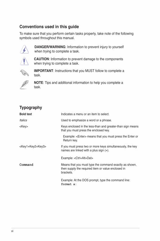
TypographyBold text Indicates a menu or an item to select.
Italics Used to emphasize a word or a phrase.
<Key> Keys enclosed in the less-than and greater-than sign means that you must press the enclosed key.
Example: <Enter> means that you must press the Enter or Return key.
<Key1+Key2+Key3> If you must press two or more keys simultaneously, the key names are linked with a plus sign (+). Example: <Ctrl+Alt+Del>
Command Means that you must type the command exactly as shown, then supply the required item or value enclosed in brackets. Example: At the DOS prompt, type the command line: format a:
DANGER/WARNING: Information to prevent injury to yourself when trying to complete a task.
CAUTION: Information to prevent damage to the components when trying to complete a task.
NOTE: Tips and additional information to help you complete a task.
IMPORTANT: Instructions that you MUST follow to complete a task.
Conventions used in this guideTo make sure that you perform certain tasks properly, take note of the following symbols used throughout this manual.
vii
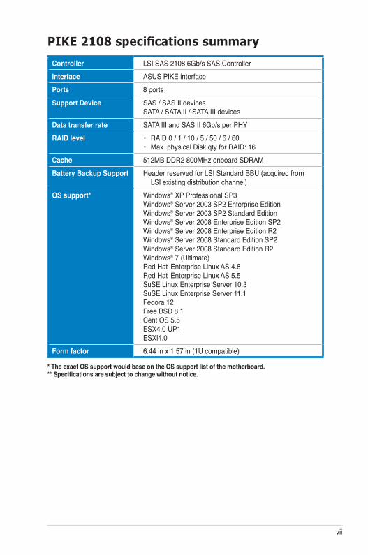
PIKE 2108 specifications summary
* The exact OS support would base on the OS support list of the motherboard.** Specifications are subject to change without notice.
Controller LSI SAS 2108 6Gb/s SAS ControllerInterface ASUS PIKE interfacePorts 8 portsSupport Device SAS / SAS II devices
SATA / SATA II / SATA III devicesData transfer rate SATA III and SAS II 6Gb/s per PHYRAID level • RAID 0 / 1 / 10 / 5 / 50 / 6 / 60
• Max. physical Disk qty for RAID: 16Cache 512MB DDR2 800MHz onboard SDRAMBattery Backup Support Header reserved for LSI Standard BBU (acquired from
LSI existing distribution channel)OS support* Windows® XP Professional SP3
Windows® Server 2003 SP2 Enterprise Edition Windows® Server 2003 SP2 Standard Edition Windows® Server 2008 Enterprise Edition SP2 Windows® Server 2008 Enterprise Edition R2 Windows® Server 2008 Standard Edition SP2 Windows® Server 2008 Standard Edition R2 Windows® 7 (Ultimate) Red Hat Enterprise Linux AS 4.8 Red Hat Enterprise Linux AS 5.5 SuSE Linux Enterprise Server 10.3 SuSE Linux Enterprise Server 11.1 Fedora 12 Free BSD 8.1 Cent OS 5.5 ESX4.0 UP1 ESXi4.0
Form factor 6.44 in x 1.57 in (1U compatible)

viii

1Chapter 1: Product introduction
This chapter offers the PIKE 2108 SAS RAID card features and the new technologies it supports.
1-2 Chapter 1: Product introduction
1.1 Welcome!Thank you for buying an ASUS® PIKE 2108 SAS RAID card!
The ASUS PIKE 2108 allows you to create RAID 0, 1, 10, 5, 50, 6, and 60 sets from SATA/SATA II/SATA III/SAS/SAS II hard disk drives connected to the SAS connectors on the motherboard.
Before you start installing the RAID card, check the items in your package with the list below.
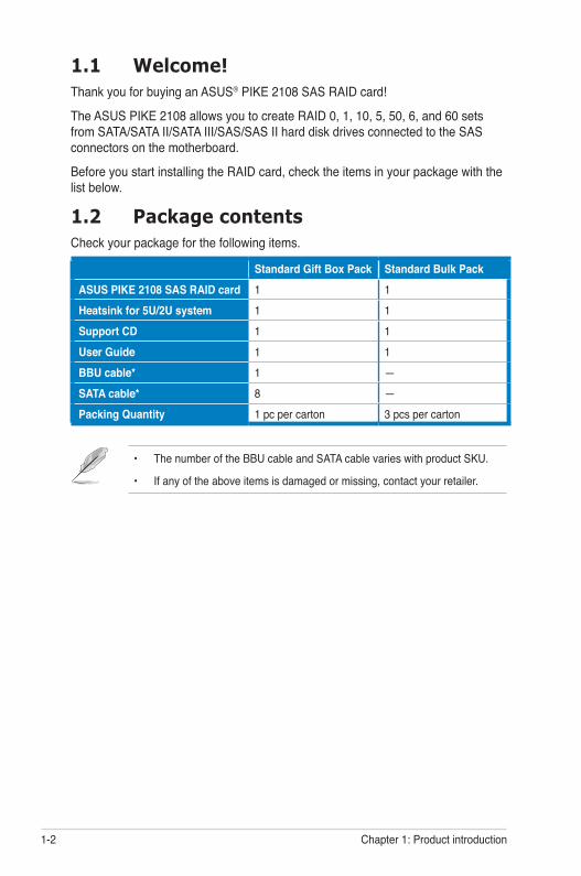
1.2 Package contentsCheck your package for the following items.
Standard Gift Box Pack Standard Bulk PackASUS PIKE 2108 SAS RAID card 1 1Heatsink for 5U/2U system 1 1Support CD 1 1User Guide 1 1BBU cable* 1 —SATA cable* 8 —Packing Quantity 1 pc per carton 3 pcs per carton
• The number of the BBU cable and SATA cable varies with product SKU.
• If any of the above items is damaged or missing, contact your retailer.
ASUS PIKE 2108 1-3
1
2
2 2 1 1
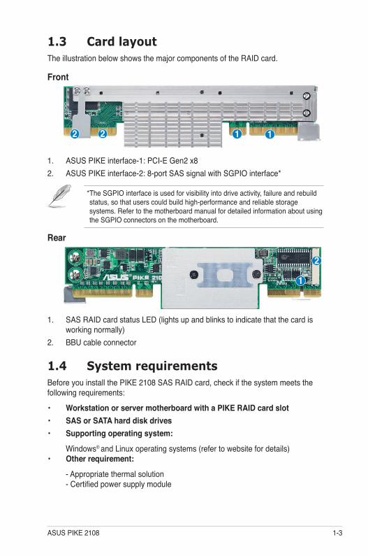
1.3 Card layoutThe illustration below shows the major components of the RAID card.
Front
1. SAS RAID card status LED (lights up and blinks to indicate that the card is working normally)
2. BBU cable connector
Rear
1. ASUS PIKE interface-1: PCI-E Gen2 x82. ASUS PIKE interface-2: 8-port SAS signal with SGPIO interface*
* The SGPIO interface is used for visibility into drive activity, failure and rebuild status, so that users could build high-performance and reliable storage systems. Refer to the motherboard manual for detailed information about using the SGPIO connectors on the motherboard.
1.4 System requirementsBefore you install the PIKE 2108 SAS RAID card, check if the system meets the following requirements:
• Workstation or server motherboard with a PIKE RAID card slot• SAS or SATA hard disk drives• Supporting operating system:
Windows® and Linux operating systems (refer to website for details)• Other requirement:
- Appropriate thermal solution- Certified power supply module
1-4 Chapter 1: Product introduction
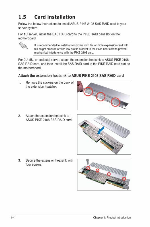
3. Secure the extension heatsink with four screws.
2. Attach the extension heatsink to ASUS PIKE 2108 SAS RAID card.
1.5 Card installationFollow the below instructions to install ASUS PIKE 2108 SAS RAID card to your server system.
For 1U server, install the SAS RAID card to the PIKE RAID card slot on the motherboard.
It is recommended to install a low-profile form factor PCIe expansion card with full height bracket, or with low profile bracket to the PCIe riser card to prevent mechanical interference with the PIKE 2108 card.
For 2U, 5U, or pedestal server, attach the extension heatsink to ASUS PIKE 2108 SAS RAID card, and then install the SAS RAID card to the PIKE RAID card slot on the motherboard.
Attach the extension heatsink to ASUS PIKE 2108 SAS RAID card1. Remove the stickers on the back of
the extension heatsink.
ASUS PIKE 2108 1-5
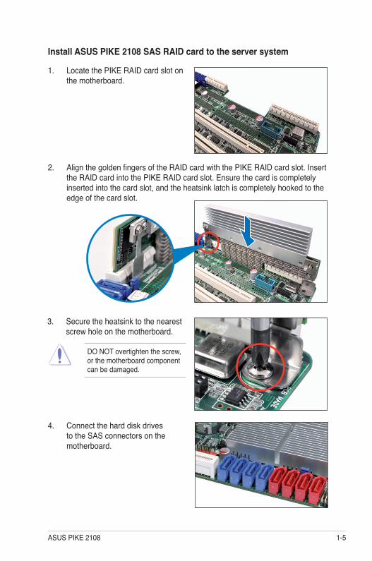
1. Locate the PIKE RAID card slot on the motherboard.
2. Align the golden fingers of the RAID card with the PIKE RAID card slot. Insert the RAID card into the PIKE RAID card slot. Ensure the card is completely inserted into the card slot, and the heatsink latch is completely hooked to the edge of the card slot.
Install ASUS PIKE 2108 SAS RAID card to the server system
3. Secure the heatsink to the nearest screw hole on the motherboard.
DO NOT overtighten the screw, or the motherboard component can be damaged.
4. Connect the hard disk drives to the SAS connectors on the motherboard.
1-6 Chapter 1: Product introduction
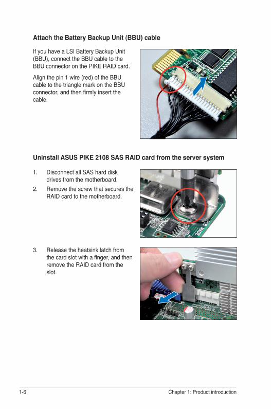
Uninstall ASUS PIKE 2108 SAS RAID card from the server system
1. Disconnect all SAS hard disk drives from the motherboard.
2. Remove the screw that secures the RAID card to the motherboard.
3. Release the heatsink latch from the card slot with a finger, and then remove the RAID card from the slot.
If you have a LSI Battery Backup Unit (BBU), connect the BBU cable to the BBU connector on the PIKE RAID card.
Align the pin 1 wire (red) of the BBU cable to the triangle mark on the BBU connector, and then firmly insert the cable.
Attach the Battery Backup Unit (BBU) cable
2Chapter 2: RAID configuration
This chapter provides instructions on setting up, creating, and configuring RAID sets using the available utilities.
2-2 Chapter 2: RAID configuration
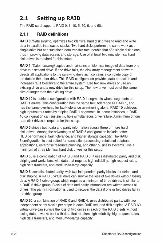
2.1 Setting up RAIDThe RAID card supports RAID 0, 1, 10, 5, 50, 6, and 60.
2.1.1 RAID definitionsRAID 0 (Data striping) optimizes two identical hard disk drives to read and write data in parallel, interleaved stacks. Two hard disks perform the same work as a single drive but at a sustained data transfer rate, double that of a single disk alone, thus improving data access and storage. Use of at least two new identical hard disk drives is required for this setup.
RAID 1 (Data mirroring) copies and maintains an identical image of data from one drive to a second drive. If one drive fails, the disk array management software directs all applications to the surviving drive as it contains a complete copy of the data in the other drive. This RAID configuration provides data protection and increases fault tolerance to the entire system. Use two new drives or use an existing drive and a new drive for this setup. The new drive must be of the same size or larger than the existing drive.
RAID 10 is a striped configuration with RAID 1 segments whose segments are RAID 1 arrays. This configuration has the same fault tolerance as RAID 1, and has the same overhead for fault-tolerance as mirroring alone. RAID 10 achieves high input/output rates by striping RAID 1 segments. In some instances, a RAID 10 configuration can sustain multiple simultaneous drive failure. A minimum of four hard disk drives is required for this setup.
RAID 5 stripes both data and parity information across three or more hard disk drives. Among the advantages of RAID 5 configuration include better HDD performance, fault tolerance, and higher storage capacity. The RAID 5 configuration is best suited for transaction processing, relational database applications, enterprise resource planning, and other business systems. Use a minimum of three identical hard disk drives for this setup.
RAID 50 is a combination of RAID 0 and RAID 5. It uses distributed parity and disk striping and works best with data that requires high reliability, high request rates, high data transfers, and medium-to-large capacity.
RAID 6 uses distributed parity, with two independent parity blocks per stripe, and disk striping. A RAID 6 virtual drive can survive the loss of two drives without losing data. A RAID 6 drive group, which requires a minimum of three drives, is similar to a RAID 5 drive group. Blocks of data and parity information are written across all drives. The parity information is used to recover the data if one or two drives fail in the drive group.
RAID 60, a combination of RAID 0 and RAID 6, uses distributed parity, with two independent parity blocks per stripe in each RAID set, and disk striping. A RAID 60 virtual drive can survive the loss of two drives in each of the RAID 6 sets without losing data. It works best with data that requires high reliability, high request rates, high data transfers, and medium-to-large capacity.
ASUS PIKE 2108 2-3
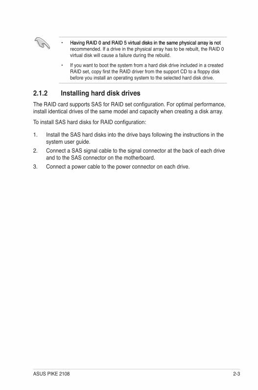
• Having RAID 0 and RAID 5 virtual disks in the same physical array is notHaving RAID 0 and RAID 5 virtual disks in the same physical array is not recommended. If a drive in the physical array has to be rebuilt, the RAID 0 virtual disk will cause a failure during the rebuild.
• If you want to boot the system from a hard disk drive included in a created RAID set, copy first the RAID driver from the support CD to a floppy disk before you install an operating system to the selected hard disk drive.
2.1.2 Installing hard disk drivesThe RAID card supports SAS for RAID set configuration. For optimal performance, install identical drives of the same model and capacity when creating a disk array.
To install SAS hard disks for RAID configuration:
1. Install the SAS hard disks into the drive bays following the instructions in the system user guide.
2. Connect a SAS signal cable to the signal connector at the back of each drive and to the SAS connector on the motherboard.
3. Connect a power cable to the power connector on each drive.
2-4 Chapter 2: RAID configuration
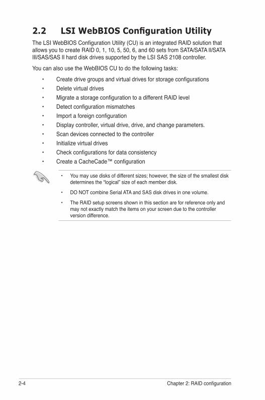
2.2 LSI WebBIOS Configuration UtilityThe LSI WebBIOS Configuration Utility (CU) is an integrated RAID solution that allows you to create RAID 0, 1, 10, 5, 50, 6, and 60 sets from SATA/SATA II/SATA III/SAS/SAS II hard disk drives supported by the LSI SAS 2108 controller.
You can also use the WebBIOS CU to do the following tasks:
• Create drive groups and virtual drives for storage configurations • Delete virtual drives • Migrate a storage configuration to a different RAID level • Detect configuration mismatches • Import a foreign configuration • Display controller, virtual drive, drive, and change parameters. • Scan devices connected to the controller • Initialize virtual drives • Check configurations for data consistency • Create a CacheCade™ configuration
• You may use disks of different sizes; however, the size of the smallest disk determines the “logical” size of each member disk.
• DO NOT combine Serial ATA and SAS disk drives in one volume.
• The RAID setup screens shown in this section are for reference only and may not exactly match the items on your screen due to the controller version difference.
ASUS PIKE 2108 2-5
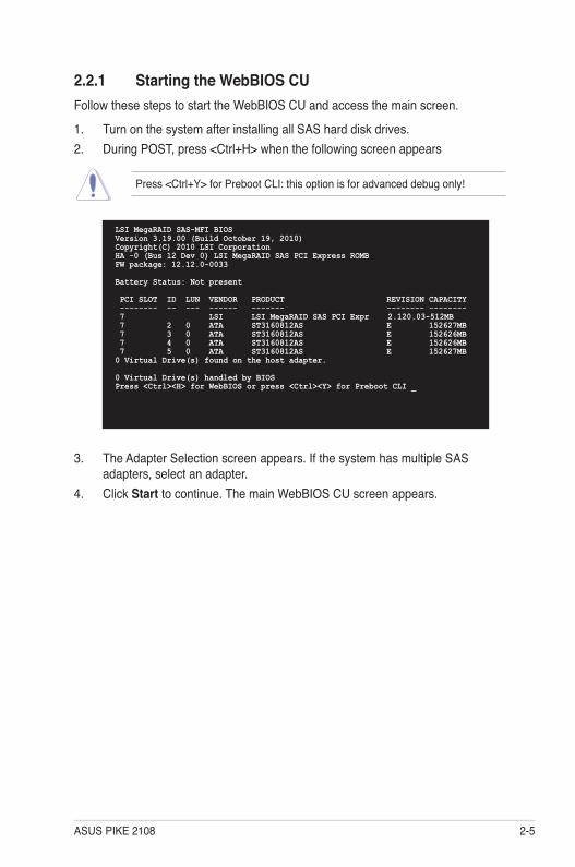
3. The Adapter Selection screen appears. If the system has multiple SAS adapters, select an adapter.
4. Click Start to continue. The main WebBIOS CU screen appears.
2.2.1 Starting the WebBIOS CUFollow these steps to start the WebBIOS CU and access the main screen.
1. Turn on the system after installing all SAS hard disk drives.2. During POST, press <Ctrl+H> when the following screen appears
Press <Ctrl+Y> for Preboot CLI: this option is for advanced debug only!
LSI MegaRAID SAS-MFI BIOSVersion 3.19.00 (Build October 19, 2010)Copyright(C) 2010 LSI CorporationHA -0 (Bus 12 Dev 0) LSI MegaRAID SAS PCI Express ROMBFW package: 12.12.0-0033
Battery Status: Not present
PCI SLOT ID LUN VENDOR PRODUCT REVISION CAPACITY -------- -- --- ------ ------- -------- -------- 7 LSI LSI MegaRAID SAS PCI Expr 2.120.03-512MB 7 2 0 ATA ST3160812AS E 152627MB 7 3 0 ATA ST3160812AS E 152626MB 7 4 0 ATA ST3160812AS E 152626MB 7 5 0 ATA ST3160812AS E 152627MB0 Virtual Drive(s) found on the host adapter.
0 Virtual Drive(s) handled by BIOSPress <Ctrl><H> for WebBIOS or press <Ctrl><Y> for Preboot CLI _
2-6 Chapter 2: RAID configuration
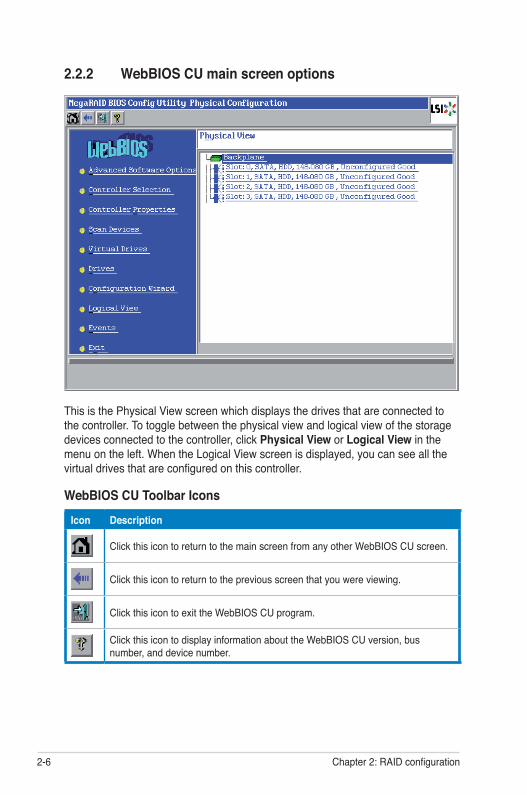
WebBIOS CU Toolbar Icons
Icon Description
Click this icon to return to the main screen from any other WebBIOS CU screen.
Click this icon to return to the previous screen that you were viewing.
Click this icon to exit the WebBIOS CU program.
Click this icon to display information about the WebBIOS CU version, bus number, and device number.
2.2.2 WebBIOS CU main screen options
This is the Physical View screen which displays the drives that are connected to the controller. To toggle between the physical view and logical view of the storage devices connected to the controller, click Physical View or Logical View in the menu on the left. When the Logical View screen is displayed, you can see all the virtual drives that are configured on this controller.
ASUS PIKE 2108 2-7
Here is a description of the options listed on the left of the main WebBIOS CU screen:
• Advanced Software Option: Select this to allow you to enable the special functionality or features that may not be available in the standard configuration of the controller.
• Controller Selection: Select this to view the Adapter Selection screen, where you can select a different SAS adapter. You can then view information about the controller and the devices connected to it, or create a new configuration on the controller.
• Controller Properties: Select this to view the properties of the currently selected SAS controller.
• Scan Devices: Select this to have the WebBIOS CU re-scan the physical and virtual drives for any changes in the drive status or the physical configuration. The WebBIOS CU displays the results of the scan in the physical and virtual drive descriptions.
• Virtual Drives: Select this to view the Virtual Drives screen, where you can change and view virtual drive properties, initialize drives, and perform other tasks.
• Drives: Select this to view the Drives screen, where you can view drive properties, and perform other tasks.
• Configuration Wizard: Select this to start the Configuration Wizard and create a new storage configuration, clear a configuration, or add a configuration.
• Logical View: Select this to toggle between the Physical View and Logical View screens.
• Events: Select this to view system events in the Event Information screen.• Exit: Select this to exit the WebBIOS CU and continue with system boot.
2-8 Chapter 2: RAID configuration
2.2.3 Creating a Storage ConfigurationThis section explains how to use the WebBIOS CU Configuration Wizard to configure RAID arrays and virtual drives.
The default settings of the configuration items mentioned in this section are subject to change without notice, but the functions of the items will not be affected.
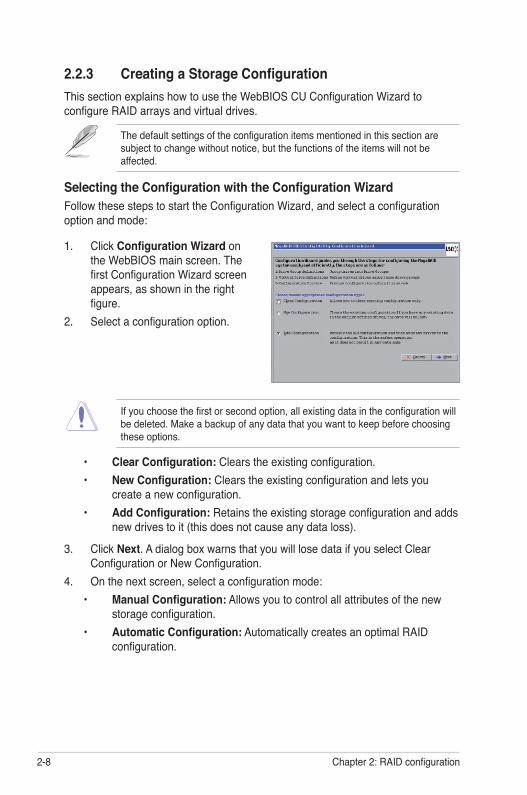
Selecting the Configuration with the Configuration WizardFollow these steps to start the Configuration Wizard, and select a configuration option and mode:
1. Click Configuration Wizard on the WebBIOS main screen. The first Configuration Wizard screen appears, as shown in the right figure.
2. Select a configuration option.
If you choose the first or second option, all existing data in the configuration will be deleted. Make a backup of any data that you want to keep before choosing these options.
• Clear Configuration: Clears the existing configuration. • New Configuration: Clears the existing configuration and lets you
create a new configuration. • Add Configuration: Retains the existing storage configuration and adds
new drives to it (this does not cause any data loss).
3. Click Next. A dialog box warns that you will lose data if you select Clear Configuration or New Configuration.
4. On the next screen, select a configuration mode: • Manual Configuration: Allows you to control all attributes of the new
storage configuration. • Automatic Configuration: Automatically creates an optimal RAID
configuration.
ASUS PIKE 2108 2-9
If you select Automatic Configuration, you can choose the redundancy mode: • Redundancy when possible: Automatically creates an optimal RAID
configuration, providing data redundancy. • No Redundancy: Automatically creates a non-redundant RAID 0
configuration.
5. Click Next to continue.
Using Automatic ConfigurationFollow these instructions to create a configuration with automatic configuration, either with or without redundancy:
1. When WebBIOS displays the proposed new configuration, review the information on the screen, and click Accept to accept it. (Or click Back to go back and change the configuration.)
• RAID 0: If you selected Automatic Configuration and No Redundancy, WebBIOS creates a RAID 0 configuration.
• RAID 1: If you selected Automatic Configuration and Redundancy when possible, WebBIOS creates a RAID 1 configuration if only two disk drives are available.
• RAID 6: If you selected Automatic Configuration and Redundancy when possible, WebBIOS creates a RAID 6 configuration if three or more disk drives are available.
2. Click Yes when you are prompted to save the configuration.3. Click Yes when you are prompted to initialize the new virtual drive(s). WebBIOS CU begins a background initialization of the virtual drives.
Using Manual Configuration: RAID 0RAID 0 provides drive striping across all drives in the RAID drive group. RAID 0 does not provide any data redundancy but does offer excellent performance. RAID 0 is ideal for applications that require high bandwidth but do not require fault tolerance. RAID 0 also denotes an independent or single drive.
RAID level 0 is not fault-tolerant. If a drive in a RAID 0 drive group fails, the whole virtual drive (all drives associated with the virtual drive) fails.
When you select Manual Configuration and click Next, the Drive Group Definition screen appears. You use this screen to select drives to create drive groups.
1. Hold <Ctrl> while selecting two or more ready drives in the Drives panel on the left until you have selected all desired drives for the drive group.
2-10 Chapter 2: RAID configuration
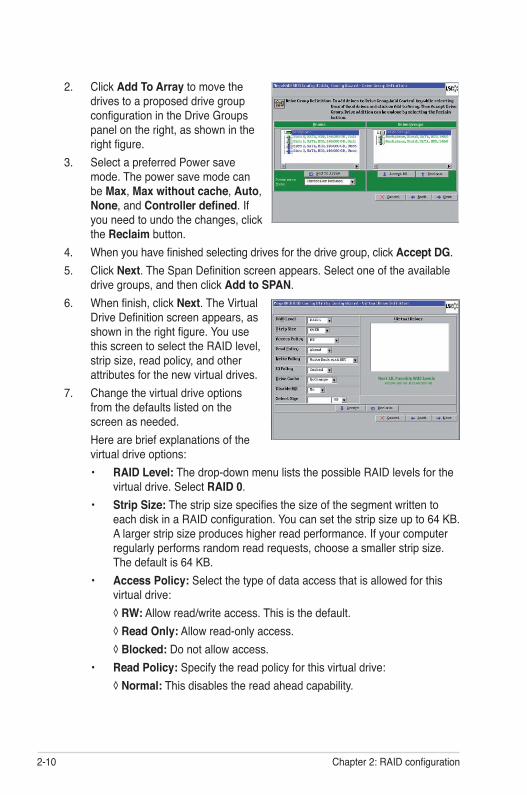
2. Click Add To Array to move the drives to a proposed drive group configuration in the Drive Groups panel on the right, as shown in the right figure.
3. Select a preferred Power save mode. The power save mode can be Max, Max without cache, Auto, None, and Controller defined. If you need to undo the changes, click the Reclaim button.
4. When you have finished selecting drives for the drive group, click Accept DG.5. Click Next. The Span Definition screen appears. Select one of the available
drive groups, and then click Add to SPAN.6. When finish, click Next. The Virtual
Drive Definition screen appears, as shown in the right figure. You use this screen to select the RAID level, strip size, read policy, and other attributes for the new virtual drives.
7. Change the virtual drive options from the defaults listed on the screen as needed.
Here are brief explanations of the virtual drive options:• RAID Level: The drop-down menu lists the possible RAID levels for the
virtual drive. Select RAID 0.• Strip Size: The strip size specifies the size of the segment written to
each disk in a RAID configuration. You can set the strip size up to 64 KB. A larger strip size produces higher read performance. If your computer regularly performs random read requests, choose a smaller strip size. The default is 64 KB.
• Access Policy: Select the type of data access that is allowed for this virtual drive:
◊ RW: Allow read/write access. This is the default. ◊ Read Only: Allow read-only access. ◊ Blocked: Do not allow access.• Read Policy: Specify the read policy for this virtual drive: ◊ Normal: This disables the read ahead capability.
ASUS PIKE 2108 2-11
◊ Ahead: This enables read ahead capability, which allows the controller to read sequentially ahead of requested data and to store the additional data in cache memory, anticipating that the data will be needed soon. This speeds up reads for sequential data, but there is little improvement when accessing random data. This is the default.
• Write Policy: Specify the write policy for this virtual drive: ◊ Write Through: In Write Through mode the controller sends a data
transfer completion signal to the host when the drive subsystem has received all of the data in a transaction.
◊ Always Write Back: In Writeback mode the controller sends a data transfer completion signal to the host when the controller cache has received all of the data in a transaction. This setting is recommended in Standard mode.
◊ Write Back with BBU: In Writeback mode the controller sends a data transfer completion signal to the host when the controller cache has received all of the data in a transaction. This setting has to be used with a Battery Backup Unit (BBU). This is the default.
• IO Policy: The IO Policy applies to reads on a specific virtual drive. It does not affect the read ahead cache.
◊ Direct: In direct I/O mode, reads are not buffered in cache memory. Data is transferred to the cache and the host concurrently. If the same data block is read again, it comes from cache memory.
◊ Cached: In cached I/O mode, all reads are buffered in cache memory. This is the default.
• Drive Cache: Specify the drive cache policy: ◊ NoChange: Leave the current drive cache policy unchanged. This is
the default. ◊ Enable: Enable the drive cache. ◊ Disable: Disable the drive cache. • Disable BGI: Specify the background initialization status: ◊ No: Leave background initialization enabled. This means that a new
configuration can be initialized in the background while you use WebBIOS to do other configuration tasks. This is the default.
◊ Yes: Select Yes if you do not want to allow background initializations for configurations on this controller.
• Select Size: Specify the size of the virtual drive in terabytes, gigabytes, megabytes, or kilobytes. Normally, this would be the full size for RAID 0 shown in the Configuration panel on the right. You may specify a smaller size if you want to create other virtual drives on the same drive group.
2-12 Chapter 2: RAID configuration
8. Click Accept to accept the changes to the virtual drive definition, or click Reclaim to return to the previous settings.
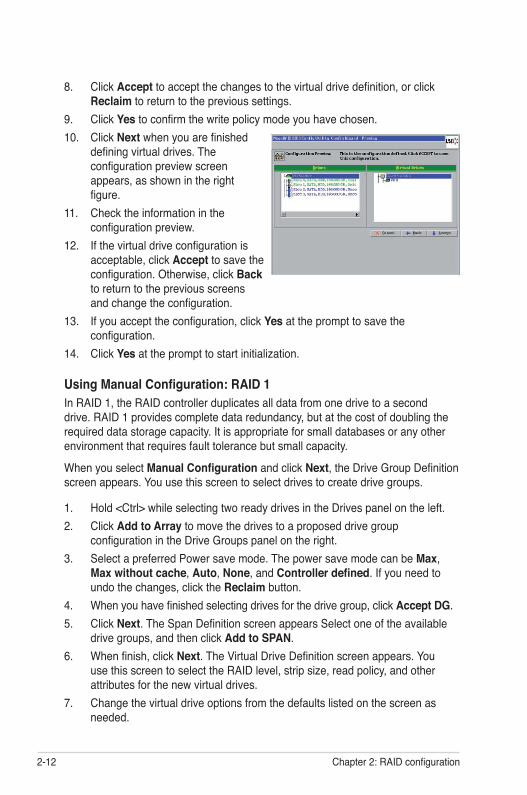
9. Click Yes to confirm the write policy mode you have chosen.10. Click Next when you are finished
defining virtual drives. The configuration preview screen appears, as shown in the right figure.
11. Check the information in the configuration preview.
12. If the virtual drive configuration is acceptable, click Accept to save the configuration. Otherwise, click Back to return to the previous screens and change the configuration.
13. If you accept the configuration, click Yes at the prompt to save the configuration.
14. Click Yes at the prompt to start initialization.
Using Manual Configuration: RAID 1In RAID 1, the RAID controller duplicates all data from one drive to a second drive. RAID 1 provides complete data redundancy, but at the cost of doubling the required data storage capacity. It is appropriate for small databases or any other environment that requires fault tolerance but small capacity.
When you select Manual Configuration and click Next, the Drive Group Definition screen appears. You use this screen to select drives to create drive groups.
1. Hold <Ctrl> while selecting two ready drives in the Drives panel on the left.2. Click Add to Array to move the drives to a proposed drive group
configuration in the Drive Groups panel on the right.3. Select a preferred Power save mode. The power save mode can be Max,
Max without cache, Auto, None, and Controller defined. If you need to undo the changes, click the Reclaim button.
4. When you have finished selecting drives for the drive group, click Accept DG.5. Click Next. The Span Definition screen appears Select one of the available
drive groups, and then click Add to SPAN.6. When finish, click Next. The Virtual Drive Definition screen appears. You
use this screen to select the RAID level, strip size, read policy, and other attributes for the new virtual drives.
7. Change the virtual drive options from the defaults listed on the screen as needed.
ASUS PIKE 2108 2-13
Here are brief explanations of the virtual drive options:• RAID Level: The drop-down menu lists the possible RAID levels for the
virtual drive. Select RAID 1.• Strip Size: The strip size specifies the size of the segment written to
each disk in a RAID configuration. You can set the strip size up to 64 KB. A larger strip size produces higher read performance. If your computer regularly performs random read requests, choose a smaller strip size. The default is 64 KB.
• Access Policy: Select the type of data access that is allowed for this virtual drive:
◊ RW: Allow read/write access. This is the default. ◊ Read Only: Allow read-only access. ◊ Blocked: Do not allow access.• Read Policy: Specify the read policy for this virtual drive: ◊ Normal: This disables the read ahead capability. ◊ Ahead: This enables read ahead capability, which allows the
controller to read sequentially ahead of requested data and to store the additional data in cache memory, anticipating that the data will be needed soon. This speeds up reads for sequential data, but there is little improvement when accessing random data. This is the default.
• Write Policy: Specify the write policy for this virtual drive: ◊ Write Through: In Write Through mode the controller sends a data
transfer completion signal to the host when the drive subsystem has received all of the data in a transaction.
◊ Always Write Back: In Writeback mode the controller sends a data transfer completion signal to the host when the controller cache has received all of the data in a transaction. This setting is recommended in Standard mode.
◊ Write Back with BBU: In Writeback mode the controller sends a data transfer completion signal to the host when the controller cache has received all of the data in a transaction. This setting has to be used with a Battery Backup Unit (BBU). This is the default.
• IO Policy: The IO Policy applies to reads on a specific virtual drive. It does not affect the read ahead cache.
◊ Direct: In direct I/O mode, reads are not buffered in cache memory. Data is transferred to the cache and the host concurrently. If the same data block is read again, it comes from cache memory.
◊ Cached: In cached I/O mode, all reads are buffered in cache memory. This is the default.
• Drive Cache: Specify the drive cache policy:
2-14 Chapter 2: RAID configuration
◊ NoChange: Leave the current drive cache policy unchanged. This is the default.
◊ Enable: Enable the drive cache. ◊ Disable: Disable the drive cache. • Disable BGI: Specify the background initialization status: ◊ No: Leave background initialization enabled. This means that a new
configuration can be initialized in the background while you use WebBIOS to do other configuration tasks. This is the default.
◊ Yes: Select Yes if you do not want to allow background initializations for configurations on this controller.
• Select Size: Specify the size of the virtual drive in terabytes, gigabytes, megabytes, or kilobytes. Normally, this would be the full size for RAID 1 shown in the Configuration panel on the right. You may specify a smaller size if you want to create other virtual drives on the same drive group.
8. Click Accept to accept the changes to the virtual drive definition, or click Reclaim to return to the previous settings.
9. Click Yes to confirm the write policy mode you have chosen.10. Click Next when you are finished defining virtual disks. The configuration
preview screen appears.11. Check the information in the configuration preview.12. If the virtual drive configuration is acceptable, click Accept to save the
configuration. Otherwise, click Back to return to the previous screens and change the configuration.
13. If you accept the configuration, click Yes at the prompt to save the configuration.
14. Click Yes at the prompt to start initialization.
Using Manual Configuration: RAID 10RAID 10, a combination of RAID 1 and RAID 0, has mirrored drives. It breaks up data into smaller blocks, then stripes the blocks of data to each RAID 1 drive group. Each RAID 1 drive group then duplicates its data to its other drive. The size of each block is determined by the strip size parameter. RAID 10 can sustain one drive failure in each array while maintaining data integrity.
RAID 10 provides both high data transfer rates and complete data redundancy. It works best for data storage that must have 100 percent redundancy of RAID 1 (mirrored drive groups) and that also needs the enhanced I/O performance of RAID 0 (striped drive groups); it works well for medium-sized databases or any environment that requires a higher degree of fault tolerance and moderate to medium capacity.
ASUS PIKE 2108 2-15
When you select Manual Configuration and click Next, the Drive Group Definition screen appears.
You use the Drive Group Definition screen to select drives to create drive groups.
1. Hold <Ctrl> while selecting two ready drives in the Drives panel on the left.2. Click Add to Array to move the drives to a proposed two-drive drive group
configuration in the Drive Groups panel on the right.3. Select a preferred Power save mode. The power save mode can be Max,
Max without cache, Auto, None, and Controller defined. If you need to undo the changes, click the Reclaim button.
4. Click Accept DG to create a RAID 1 drive group. An icon for the next drive group displays in the right panel.5. Click on the icon for the next drive group to select it.6. Hold <Ctrl> while selecting two more ready drives in the Drives panel to
create a second RAID 1 drive group with two drives.7. Click Add To Array to move the drives to a second two-drive drive group
configuration in the Drive Groups panel. If you need to undo the changes, click the Reclaim button.8. Repeat the previous three steps until you have selected all the drives you
want for the drive groups.9. After you finish selecting drives for the drive groups, select each drive group
and click Accept DG for each.10. Click Next. The Span Definition screen appears. This screen displays the
drive group holes you can select to add to a span.11. Select one of the available drive groups with two drives from the Array With
Free Space drop-down list, and then click Add to SPAN. 12. Select a second drive group from the Array With Free Space drop-down list,
and click Add to SPAN. Both drive groups display in the right frame under Span.13. If there are additional drive groups with two drives each, you can add them to
the virtual drive.14. When finish, click Next. The Virtual Drive Definition screen appears. You use this screen to select the RAID level, strip size, read policy, and other
attributes for the new virtual drives.
The WebBIOS Configuration Utility displays the maximum available capacity while creating the RAID 10 drive group. In version 1.03 of the utility, the maximum size of the RAID 10 drive group is the sum total of the two RAID 1 drive groups. In version 1.1, the maximum size is the size of the smaller drive group multiplied by two.
2-16 Chapter 2: RAID configuration
15. Change the virtual drive options from the defaults listed on the screen as needed.
Here are brief explanations of the virtual drive options:• RAID Level: The drop-down menu lists the possible RAID levels for the
virtual drive. Select RAID 10.• Strip Size: The strip size specifies the size of the segment written to
each disk in a RAID configuration. You can set the strip size up to 64 KB. A larger strip size produces higher read performance. If your computer regularly performs random read requests, choose a smaller strip size. The default is 64 KB.
• Access Policy: Select the type of data access that is allowed for this virtual drive:
◊ RW: Allow read/write access. This is the default. ◊ Read Only: Allow read-only access. ◊ Blocked: Do not allow access.• Read Policy: Specify the read policy for this virtual drive: ◊ Normal: This disables the read ahead capability. ◊ Ahead: This enables read ahead capability, which allows the
controller to read sequentially ahead of requested data and to store the additional data in cache memory, anticipating that the data will be needed soon. This speeds up reads for sequential data, but there is little improvement when accessing random data. This is the default.
• Write Policy: Specify the write policy for this virtual drive: ◊ Write Through: In Write Through mode the controller sends a data
transfer completion signal to the host when the drive subsystem has received all of the data in a transaction.
◊ Always Write Back: In Writeback mode the controller sends a data transfer completion signal to the host when the controller cache has received all of the data in a transaction. This setting is recommended in Standard mode.
◊ Write Back with BBU: In Writeback mode the controller sends a data transfer completion signal to the host when the controller cache has received all of the data in a transaction. This setting has to be used with a Battery Backup Unit (BBU). This is the default.
• IO Policy: The IO Policy applies to reads on a specific virtual drive. It does not affect the read ahead cache.
◊ Direct: In direct I/O mode, reads are not buffered in cache memory. Data is transferred to the cache and the host concurrently. If the same data block is read again, it comes from cache memory.
◊ Cached: In cached I/O mode, all reads are buffered in cache memory. This is the default.
ASUS PIKE 2108 2-17
• Drive Cache: Specify the drive cache policy: ◊ NoChange: Leave the current drive cache policy unchanged. This is
the default. ◊ Enable: Enable the drive cache. ◊ Disable: Disable the drive cache. • Disable BGI: Specify the background initialization status: ◊ No: Leave background initialization enabled. This means that a new
configuration can be initialized in the background while you use WebBIOS to do other configuration tasks. This is the default.
◊ Yes: Select Yes if you do not want to allow background initializations for configurations on this controller.
• Select Size: Specify the size of the virtual drive in terabytes, gigabytes, megabytes, or kilobytes. Normally, this would be the full size for RAID 10 shown in the Configuration panel on the right. You may specify a smaller size if you want to create other virtual drives on the same drive group.
16. Click Accept to accept the changes to the virtual drive definition, or click Reclaim to to undo the changes.
17. Click Yes to confirm the write policy mode you have chosen.18. When you are finished defining virtual drives, click Next. The configuration
preview screen appears.19. Check the information in the configuration preview.20. If the virtual drive configuration is acceptable, click Accept to save the
configuration. Otherwise, click Cancel to end the operation and return to the WebBIOS main menu, or click Back to return to the previous screens and change the configuration.
21. If you accept the configuration, click Yes at the prompt to save the configuration.
22. Click Yes at the prompt to start initialization.
Using Manual Configuration: RAID 5RAID 5 uses drive striping at the block level and parity. In RAID 5, the parity information is written to all drives. It is best suited for networks that perform a lot of small input/output (I/O) transactions simultaneously. RAID 5 provides data redundancy, high read rates, and good performance in most environments. It also provides redundancy with lowest loss of capacity.
RAID 5 provides high data throughput. RAID 5 is useful for transaction processing applications because each drive can read and write independently. If a drive fails, the RAID controller uses the parity drive to recreate all missing information. You can use RAID 5 for office automation and online customer service that require fault tolerance. In addition, RAID 5 is good for any application that has high read request rates but low write request rates.
2-18 Chapter 2: RAID configuration
When you select Manual Configuration and click Next, the Drive Group Definition screen appears. You use this screen to select drives to create drive groups.
1. Hold <Ctrl> while you select at least three ready drives in the Drives panel on the left.
2. Click Add To Arrary to move the drives to a proposed drive group configuration in the Drive Groups panel on the right.
3. Select a preferred Power save mode. The power save mode can be Max, Max without cache, Auto, None, and Controller defined. If you need to undo the changes, click the Reclaim button.
4. When you have finished selecting drives for the drive group, click Accept DG.
5. Click Next. The Span Definition screen appears. Select one of the available drive groups, and then click Add to SPAN.
6. When finish, click Next. The Virtual Drive Definition screen appears. You use this screen to select the RAID level, strip size, read policy, and other attributes for the new virtual drives.
7. Change the virtual drive options from the defaults listed on the screen as needed.
Here are brief explanations of the virtual disk options:• RAID Level: The drop-down menu lists the possible RAID levels for the
virtual drive. Select RAID 5.• Strip Size: The strip size specifies the size of the segment written to
each disk in a RAID configuration. You can set the strip size up to 64 KB. A larger strip size produces higher read performance. If your computer regularly performs random read requests, choose a smaller strip size. The default is 64 KB.
• Access Policy: Select the type of data access that is allowed for this virtual drive:
◊ RW: Allow read/write access. This is the default. ◊ Read Only: Allow read-only access. ◊ Blocked: Do not allow access.• Read Policy: Specify the read policy for this virtual drive: ◊ Normal: This disables the read ahead capability. ◊ Ahead: This enables read ahead capability, which allows the
controller to read sequentially ahead of requested data and to store the additional data in cache memory, anticipating that the data will be needed soon. This speeds up reads for sequential data, but there is little improvement when accessing random data. This is the default.
• Write Policy: Specify the write policy for this virtual drive:
ASUS PIKE 2108 2-19
◊ Write Through: In Write Through mode the controller sends a data transfer completion signal to the host when the drive subsystem has received all of the data in a transaction.
◊ Always Write Back: In Writeback mode the controller sends a data transfer completion signal to the host when the controller cache has received all of the data in a transaction. This setting is recommended in Standard mode.
◊ Write Back with BBU: In Writeback mode the controller sends a data transfer completion signal to the host when the controller cache has received all of the data in a transaction. This setting has to be used with a Battery Backup Unit (BBU). This is the default.
• IO Policy: The IO Policy applies to reads on a specific virtual drive. It does not affect the read ahead cache.
◊ Direct: In direct I/O mode, reads are not buffered in cache memory. Data is transferred to the cache and the host concurrently. If the same data block is read again, it comes from cache memory.
◊ Cached: In cached I/O mode, all reads are buffered in cache memory. This is the default.
• Drive Cache: Specify the drive cache policy: ◊ NoChange: Leave the current drive cache policy unchanged. This is
the default. ◊ Enable: Enable the drive cache. ◊ Disable: Disable the drive cache. • Disable BGI: Specify the background initialization status: ◊ No: Leave background initialization enabled. This means that a new
configuration can be initialized in the background while you use WebBIOS to do other configuration tasks. This is the default.
◊ Yes: Select Yes if you do not want to allow background initializations for configurations on this controller.
• Select Size: Specify the size of the virtual drive in terabytes, gigabytes, megabytes, or kilobytes. Normally, this would be the full size for RAID 5 shown in the Configuration panel on the right. You may specify a smaller size if you want to create other virtual drives on the same drive group.
8. Click Accept to accept the changes to the virtual drive definition, or click Reclaim to return to the previous settings.
9. Click Yes to confirm the write policy mode you have chosen.10. Click Next when you are finished defining virtual drives. The configuration
preview screen appears.11. Check the information in the configuration preview.
2-20 Chapter 2: RAID configuration
12. If the virtual drive configuration is acceptable, click Accept to save the configuration. Otherwise, click Back to return to the previous screens and change the configuration.
13. If you accept the configuration, click Yes at the prompt to save the configuration.
14. Click Yes at the prompt to start initialization.
Using Manual Configuration: RAID 50RAID 50 provides the features of both RAID 0 and RAID 5. RAID 50 uses both distributed parity and drive striping across multiple drive groups. It provides high data throughput, data redundancy, and very good performance. It is best implemented on two RAID 5 drive groups with data striped across both drive groups. Though multiple drive failures can be tolerated, only one drive failure can be tolerated in each RAID 5 level drive group.
RAID 50 is appropriate when used with data that requires high reliability, high request rates, high data transfer, and medium to large capacity.
When you select Manual Configuration and click Next, the Drive Group Definition screen appears. You use this screen to select drives to create drive groups.
1. Hold <Ctrl> while selecting at least three ready drives in the Drives panel on the left.
2. Click Add To Array to move the drives to a proposed drive group configuration in the Drive Groups panel on the right.
3. Select a preferred Power save mode. The power save mode can be Max, Max without cache, Auto, None, and Controller defined. If you need to undo the changes, click the Reclaim button.
4. Click Accept DG to create a RAID 5 drive group. An icon for a second drive group displays in the right panel.5. Click on the icon for the second drive group to select it.6. Hold <Ctrl> while selecting at least three more ready drives in the Drives
panel to create a second drive group.7. Click Add To Array to move the drives to a proposed drive group
configuration in the Drive Groups panel on the right. If you need to undo the changes, click the Reclaim button.8. After you finish selecting drives for the drive groups, select each drive group
and click Accept DG for each.9. Click Next. The Span Definition screen appears. This screen displays the
drive group holes you can select to add to a span.10. Select one of the available drive groups from the Array With Free Space
drop-down list, and then click Add to SPAN.
ASUS PIKE 2108 2-21
11. Select a second drive group from the Array With Free Space drop-down list, and click Add to SPAN.
Both drive groups display in the right frame under Span.12. When finish, click Next. The Virtual Drive Definition screen appears. You
use this screen to select the RAID level, strip size, read policy, and other attributes for the new virtual drive(s).
13. If there are additional drive groups with three or more drives each, you can add them to the virtual drive.
14. Change the virtual drive options from the defaults listed on the screen as needed.
Here are brief explanations of the virtual drive options:• RAID Level: The drop-down menu lists the possible RAID levels for the
virtual drive. Select RAID 50.• Strip Size: The strip size specifies the size of the segment written to
each disk in a RAID configuration. You can set the strip size up to 64 KB. A larger strip size produces higher read performance. If your computer regularly performs random read requests, choose a smaller strip size. The default is 64 KB.
• Access Policy: Select the type of data access that is allowed for this virtual drive:
◊ RW: Allow read/write access. This is the default. ◊ Read Only: Allow read-only access. ◊ Blocked: Do not allow access.• Read Policy: Specify the read policy for this virtual drive: ◊ Normal: This disables the read ahead capability. ◊ Ahead: This enables read ahead capability, which allows the
controller to read sequentially ahead of requested data and to store the additional data in cache memory, anticipating that the data will be needed soon. This speeds up reads for sequential data, but there is little improvement when accessing random data. This is the default.
• Write Policy: Specify the write policy for this virtual drive: ◊ Write Through: In Write Through mode the controller sends a data
transfer completion signal to the host when the drive subsystem has received all of the data in a transaction.
◊ Always Write Back: In Writeback mode the controller sends a data transfer completion signal to the host when the controller cache has received all of the data in a transaction. This setting is recommended in Standard mode.
2-22 Chapter 2: RAID configuration
◊ Write Back with BBU: In Writeback mode the controller sends a data transfer completion signal to the host when the controller cache has received all of the data in a transaction. This setting has to be used with a Battery Backup Unit (BBU). This is the default.
• IO Policy: The IO Policy applies to reads on a specific virtual drive. It does not affect the read ahead cache.
◊ Direct: In direct I/O mode, reads are not buffered in cache memory. Data is transferred to the cache and the host concurrently. If the same data block is read again, it comes from cache memory.
◊ Cached: In cached I/O mode, all reads are buffered in cache memory. This is the default.
• Drive Cache: Specify the drive cache policy: ◊ NoChange: Leave the current drive cache policy unchanged. This is
the default. ◊ Enable: Enable the drive cache. ◊ Disable: Disable the drive cache. • Disable BGI: Specify the background initialization status: ◊ No: Leave background initialization enabled. This means that a new
configuration can be initialized in the background while you use WebBIOS to do other configuration tasks. This is the default.
◊ Yes: Select Yes if you do not want to allow background initializations for configurations on this controller.
• Select Size: Specify the size of the virtual drive in terabytes, gigabytes, megabytes, or kilobytes. Normally, this would be the full size for RAID 50 shown in the Configuration panel on the right. You may specify a smaller size if you want to create other virtual drives on the same drive group.
15. Click Accept to accept the changes to the virtual drive definition, or click Reclaim to undo the changes.
16. Click Yes to confirm the write policy mode you have chosen.17. Click Next when you are finished defining virtual drives. The configuration
preview screen appears.18. Check the information in the configuration preview.19. If the virtual drive configuration is acceptable, click Accept to save the
configuration. Otherwise, click Cancel to end the operation and return to the WebBIOS main menu, or click Back to return to the previous screens and change the configuration.
20. If you accept the configuration, click Yes at the prompt to save the configuration.
21. Click Yes at the prompt to start initialization.
ASUS PIKE 2108 2-23
Using Manual Configuration: RAID 6RAID 6 is similar to RAID 5 (drive striping and distributed parity), except that instead of one parity block per stripe, there are two. With two independent parity blocks, RAID 6 can survive the loss of two drives in a virtual drive without losing data. Use RAID 6 for data that requires a very high level of protection from loss.
RAID 6 is best suited for networks that perform a lot of small input/output (I/O) transactions simultaneously. It provides data redundancy, high read rates, and good performance in most environments.
In the case of a failure of one drive or two drives in a virtual drive, the RAID controller uses the parity blocks to recreate all of the missing information. If two drives in a RAID 6 virtual drive fail, two drive rebuilds are required, one for each drive. These rebuilds do not occur at the same time. The controller rebuilds one failed drive, and then the other failed drive.
When you select Manual Configuration and click Next, the Drive Group Definition screen appears. You use this screen to select drives to create drive groups.
1. Hold <Ctrl> while you select at least three ready drives in the Drives panel on the left.
2. Click Add To Arrary to move the drives to a proposed drive group configuration in the Drive Groups panel on the right.
3. Select a preferred Power save mode. The power save mode can be Max, Max without cache, Auto, None, and Controller defined. If you need to undo the changes, click the Reclaim button.
4. When you have finished selecting drives for the drive group, click Accept DG.
5. Click Next. The Span Definition screen appears. Select one of the available drive groups, and then click Add to SPAN.
6. When finish, click Next. The Virtual Drive Definition screen appears. You use this screen to select the RAID level, strip size, read policy, and other attributes for the new virtual drives.
7. Change the virtual drive options from the defaults listed on the screen as needed.
Here are brief explanations of the virtual disk options:• RAID Level: The drop-down menu lists the possible RAID levels for the
virtual drive. Select RAID 6.• Strip Size: The strip size specifies the size of the segment written to
each disk in a RAID configuration. You can set the strip size up to 64 KB. A larger strip size produces higher read performance. If your computer regularly performs random read requests, choose a smaller strip size. The default is 64 KB.
2-24 Chapter 2: RAID configuration
• Access Policy: Select the type of data access that is allowed for this virtual drive:
◊ RW: Allow read/write access. This is the default. ◊ Read Only: Allow read-only access. ◊ Blocked: Do not allow access.• Read Policy: Specify the read policy for this virtual drive: ◊ Normal: This disables the read ahead capability. ◊ Ahead: This enables read ahead capability, which allows the
controller to read sequentially ahead of requested data and to store the additional data in cache memory, anticipating that the data will be needed soon. This speeds up reads for sequential data, but there is little improvement when accessing random data. This is the default.
• Write Policy: Specify the write policy for this virtual drive: ◊ Write Through: In Write Through mode the controller sends a data
transfer completion signal to the host when the drive subsystem has received all of the data in a transaction.
◊ Always Write Back: In Writeback mode the controller sends a data transfer completion signal to the host when the controller cache has received all of the data in a transaction. This setting is recommended in Standard mode.
◊ Write Back with BBU: In Writeback mode the controller sends a data transfer completion signal to the host when the controller cache has received all of the data in a transaction. This setting has to be used with a Battery Backup Unit (BBU). This is the default.
• IO Policy: The IO Policy applies to reads on a specific virtual drive. It does not affect the read ahead cache.
◊ Direct: In direct I/O mode, reads are not buffered in cache memory. Data is transferred to the cache and the host concurrently. If the same data block is read again, it comes from cache memory.
◊ Cached: In cached I/O mode, all reads are buffered in cache memory. This is the default.
• Drive Cache: Specify the drive cache policy: ◊ NoChange: Leave the current drive cache policy unchanged. This is
the default. ◊ Enable: Enable the drive cache. ◊ Disable: Disable the drive cache. • Disable BGI: Specify the background initialization status:
ASUS PIKE 2108 2-25
◊ No: Leave background initialization enabled. This means that a new configuration can be initialized in the background while you use WebBIOS to do other configuration tasks. This is the default.
◊ Yes: Select Yes if you do not want to allow background initializations for configurations on this controller.
• Select Size: Specify the size of the virtual drive in terabytes, gigabytes, megabytes, or kilobytes. Normally, this would be the full size for RAID 6 shown in the Configuration panel on the right. You may specify a smaller size if you want to create other virtual drives on the same drive group.
8. Click Accept to accept the changes to the virtual drive definition, or click Reclaim to return to the previous settings.
9. Click Yes to confirm the write policy mode you have chosen.10. Click Next when you are finished defining virtual drives. The configuration
preview screen appears.11. Check the information in the configuration preview.12. If the virtual drive configuration is acceptable, click Accept to save the
configuration. Otherwise, click Back to return to the previous screens and change the configuration.
13. If you accept the configuration, click Yes at the prompt to save the configuration.
14. Click Yes at the prompt to start initialization.
Using Manual Configuration: RAID 60RAID 60 provides the features of both RAID 0 and RAID 6, and includes both parity and drive striping across multiple drive groups. RAID 6 supports two independent parity blocks per stripe. A RAID 60 virtual drive can survive the loss of two drives in each of the RAID 6 sets without losing data. RAID 60 is best implemented on two RAID 6 drive groups with data striped across both drive groups. Uses RAID 60 for data that requires a very high level of protection from loss.
RAID 60 can support up to eight spans and tolerate up to 16 drive failures, though less than total drive capacity is available. Two drive failures can be tolerated in each RAID 6 level drive group.
RAID 60 is appropriate when used with data that requires high reliability, high request rates, high data transfer, and medium to large capacity.
When you select Manual Configuration and click Next, the Drive Group Definition screen appears. You use this screen to select drives to create drive groups.
1. Hold <Ctrl> while selecting at least three ready drives in the Drives panel on the left.
2-26 Chapter 2: RAID configuration
2. Click Add To Array to move the drives to a proposed drive group configuration in the Drive Groups panel on the right.
3. Select a preferred Power save mode. The power save mode can be Max, Max without cache, Auto, None, and Controller defined. If you need to undo the changes, click the Reclaim button.
4. Click Accept DG to create a RAID 6 drive group. An icon for a second drive group displays in the right panel.5. Click on the icon for the second drive group to select it.6. Hold <Ctrl> while selecting at least three more ready drives in the Drives
panel to create a second drive group.7. Click Add To Array to move the drives to a proposed drive group
configuration in the Drive Groups panel on the right. If you need to undo the changes, click the Reclaim button.8. Choose whether to use drive encryption. After you finish selecting drives for
the drive groups, select each drive group and click Accept DG for each.9. Click Next. The Span Definition screen appears. This screen displays the
drive group holes you can select to add to a span.10. Select one of the available drive groups from the Array With Free Space
drop-down list, and then click Add to SPAN. 11. Select a second drive group from the Array With Free Space drop-down list,
and click Add to SPAN. Both drive groups display in the right frame under Span.12. When finish, click Next. The Virtual Drive Definition screen appears. You
use this screen to select the RAID level, strip size, read policy, and other attributes for the new virtual drive(s).
13. If there are additional drive groups with three or more drives each, you can add them to the virtual drive.
14. Change the virtual drive options from the defaults listed on the screen as needed.
Here are brief explanations of the virtual drive options:• RAID Level: The drop-down menu lists the possible RAID levels for the
virtual drive. Select RAID 60.• Strip Size: The strip size specifies the size of the segment written to
each disk in a RAID configuration. You can set the strip size up to 64 KB. A larger strip size produces higher read performance. If your computer regularly performs random read requests, choose a smaller strip size. The default is 64 KB.
• Access Policy: Select the type of data access that is allowed for this virtual drive:
ASUS PIKE 2108 2-27
◊ RW: Allow read/write access. This is the default. ◊ Read Only: Allow read-only access. ◊ Blocked: Do not allow access.• Read Policy: Specify the read policy for this virtual drive: ◊ Normal: This disables the read ahead capability. ◊ Ahead: This enables read ahead capability, which allows the
controller to read sequentially ahead of requested data and to store the additional data in cache memory, anticipating that the data will be needed soon. This speeds up reads for sequential data, but there is little improvement when accessing random data. This is the default.
• Write Policy: Specify the write policy for this virtual drive: ◊ Write Through: In Write Through mode the controller sends a data
transfer completion signal to the host when the drive subsystem has received all of the data in a transaction.
◊ Always Write Back: In Writeback mode the controller sends a data transfer completion signal to the host when the controller cache has received all of the data in a transaction. This setting is recommended in Standard mode.
◊ Write Back with BBU: In Writeback mode the controller sends a data transfer completion signal to the host when the controller cache has received all of the data in a transaction. This setting has to be used with a Battery Backup Unit (BBU). This is the default.
• IO Policy: The IO Policy applies to reads on a specific virtual drive. It does not affect the read ahead cache.
◊ Direct: In direct I/O mode, reads are not buffered in cache memory. Data is transferred to the cache and the host concurrently. If the same data block is read again, it comes from cache memory.
◊ Cached: In cached I/O mode, all reads are buffered in cache memory. This is the default.
• Drive Cache: Specify the drive cache policy: ◊ NoChange: Leave the current drive cache policy unchanged. This is
the default. ◊ Enable: Enable the drive cache. ◊ Disable: Disable the drive cache. • Disable BGI: Specify the background initialization status: ◊ No: Leave background initialization enabled. This means that a new
configuration can be initialized in the background while you use WebBIOS to do other configuration tasks. This is the default.
◊ Yes: Select Yes if you do not want to allow background initializations for configurations on this controller.
2-28 Chapter 2: RAID configuration
• Select Size: Specify the size of the virtual drive in terabytes, gigabytes, megabytes, or kilobytes. Normally, this would be the full size for RAID 60 shown in the Configuration panel on the right. You may specify a smaller size if you want to create other virtual drives on the same drive group.
15. Click Accept to accept the changes to the virtual drive definition, or click Reclaim to undo the changes.
16. Click Yes to confirm the write policy mode you have chosen.17. Click Next when you are finished defining virtual drives. The configuration
preview screen appears.18. Check the information in the configuration preview.19. If the virtual drive configuration is acceptable, click Accept to save the
configuration. Otherwise, click Cancel to end the operation and return to the WebBIOS main menu, or click Back to return to the previous screens and change the configuration.
20. If you accept the configuration, click Yes at the prompt to save the configuration.
21. Click Yes at the prompt to start initialization.
ASUS PIKE 2108 2-29
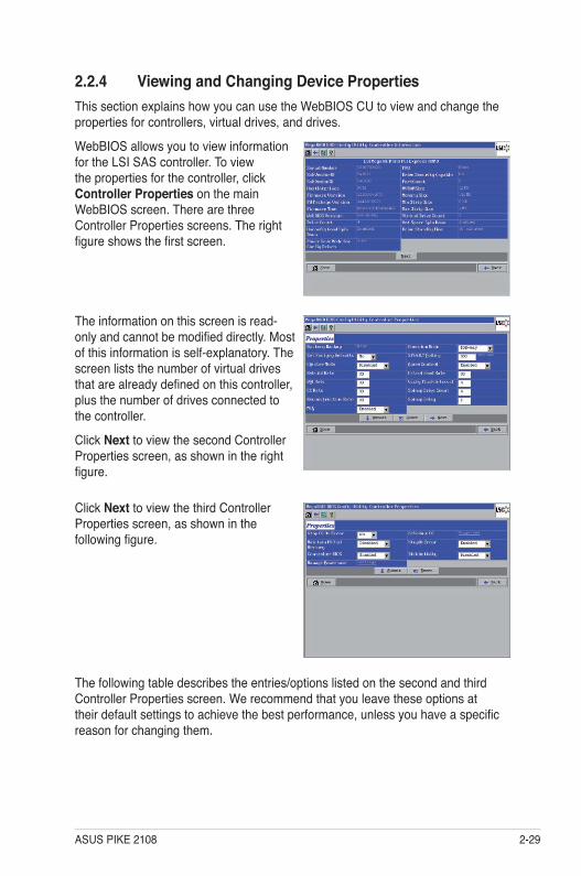
2.2.4 Viewing and Changing Device PropertiesThis section explains how you can use the WebBIOS CU to view and change the properties for controllers, virtual drives, and drives.
WebBIOS allows you to view information for the LSI SAS controller. To view the properties for the controller, click Controller Properties on the main WebBIOS screen. There are three Controller Properties screens. The right figure shows the first screen.
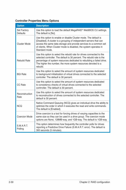
The information on this screen is read-only and cannot be modified directly. Most of this information is self-explanatory. The screen lists the number of virtual drives that are already defined on this controller, plus the number of drives connected to the controller.
Click Next to view the second Controller Properties screen, as shown in the right figure.
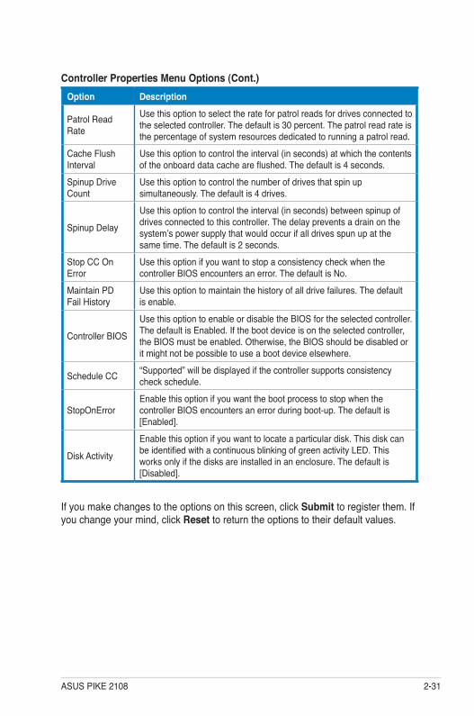
Click Next to view the third Controller Properties screen, as shown in the following figure.
The following table describes the entries/options listed on the second and third Controller Properties screen. We recommend that you leave these options at their default settings to achieve the best performance, unless you have a specific reason for changing them.
2-30 Chapter 2: RAID configuration
Controller Properties Menu OptionsOption DescriptionSet Factory Defaults
Use this option to load the default MegaRAID® WebBIOS CU settings. The default is [No].
Cluster Mode
Use this option to enable or disable Cluster mode. The default is [Disabled]. A cluster is a grouping of independent servers that can access the same data storage and provide services to a common set of clients. When Cluster mode is disabled, the system operates in Standard mode.
Rebuild Rate
Use this option to select the rebuild rate for drives connected to the selected controller. The default is 30 percent. The rebuild rate is the percentage of system resources dedicated to rebuilding a failed drive. The higher the number, the more system resources devoted to a rebuild.
BGI RateUse this option to select the amount of system resources dedicated to background initialization of virtual drives connected to the selected controller. The default is 30 percent.
CC RateUse this option to select the amount of system resources dedicated to consistency checks of virtual drives connected to the selected contrroller. The default is 30 percent.
Reconstruction Rate
Use this option to select the amount of system resources dedicated to reconstruction of drives connected to the selected controller. The default is 30 percent.
NCQNative Command Queuing (NCQ) gives an individual drive the ability to optimize the order in which it executes the read and write commands. The default is [Enabled].
Coercion ModeDrive coercion is a tool for forcing drives of varying capacities to the same size so they can be used in a drive group. The coercion mode options are None, 128MB-way, and 1GB-way. The default is 1GB-way.
S.M.A.R.T. Polling
This option determines how frequently the controller polls for drives reporting a Predictive Drive Failure (S.M.A.R.T. error). The default is 300 seconds (5 minutes).
ASUS PIKE 2108 2-31
Controller Properties Menu Options (Cont.)Option Description
Patrol Read Rate
Use this option to select the rate for patrol reads for drives connected to the selected controller. The default is 30 percent. The patrol read rate is the percentage of system resources dedicated to running a patrol read.
Cache Flush Interval
Use this option to control the interval (in seconds) at which the contents of the onboard data cache are flushed. The default is 4 seconds.
Spinup Drive Count
Use this option to control the number of drives that spin up simultaneously. The default is 4 drives.
Spinup Delay
Use this option to control the interval (in seconds) between spinup of drives connected to this controller. The delay prevents a drain on the system’s power supply that would occur if all drives spun up at the same time. The default is 2 seconds.
Stop CC On Error
Use this option if you want to stop a consistency check when the controller BIOS encounters an error. The default is No.
Maintain PD Fail History
Use this option to maintain the history of all drive failures. The default is enable.
Controller BIOS
Use this option to enable or disable the BIOS for the selected controller. The default is Enabled. If the boot device is on the selected controller, the BIOS must be enabled. Otherwise, the BIOS should be disabled or it might not be possible to use a boot device elsewhere.
Schedule CC “Supported” will be displayed if the controller supports consistency check schedule.
StopOnErrorEnable this option if you want the boot process to stop when the controller BIOS encounters an error during boot-up. The default is [Enabled].
Disk Activity
Enable this option if you want to locate a particular disk. This disk can be identified with a continuous blinking of green activity LED. This works only if the disks are installed in an enclosure. The default is [Disabled].
If you make changes to the options on this screen, click Submit to register them. If you change your mind, click Reset to return the options to their default values.
2-32 Chapter 2: RAID configuration
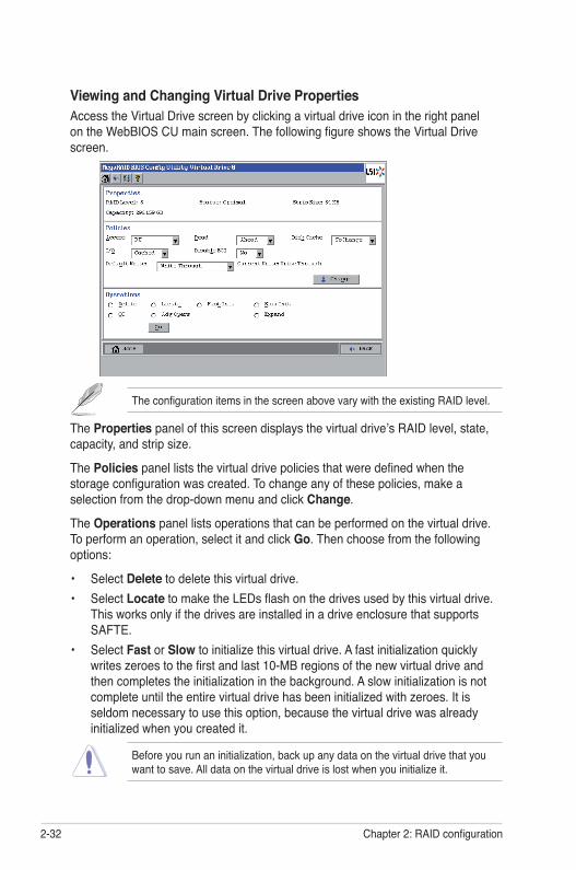
Viewing and Changing Virtual Drive PropertiesAccess the Virtual Drive screen by clicking a virtual drive icon in the right panel on the WebBIOS CU main screen. The following figure shows the Virtual Drive screen.
The configuration items in the screen above vary with the existing RAID level.
The Properties panel of this screen displays the virtual drive’s RAID level, state, capacity, and strip size.
The Policies panel lists the virtual drive policies that were defined when the storage configuration was created. To change any of these policies, make a selection from the drop-down menu and click Change.
The Operations panel lists operations that can be performed on the virtual drive. To perform an operation, select it and click Go. Then choose from the following options:
• Select Delete to delete this virtual drive. • Select Locate to make the LEDs flash on the drives used by this virtual drive.
This works only if the drives are installed in a drive enclosure that supports SAFTE.
• Select Fast or Slow to initialize this virtual drive. A fast initialization quickly writes zeroes to the first and last 10-MB regions of the new virtual drive and then completes the initialization in the background. A slow initialization is not complete until the entire virtual drive has been initialized with zeroes. It is seldom necessary to use this option, because the virtual drive was already initialized when you created it.
Before you run an initialization, back up any data on the virtual drive that you want to save. All data on the virtual drive is lost when you initialize it.
ASUS PIKE 2108 2-33
• Select CC to run a consistency check on this virtual drive.
Before you change a virtual drive configuration, back up any data on the virtual drive that you want to save.
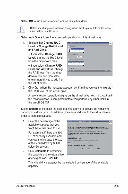
• Select Adv Opers to set the advanced operations on this virtual drive.
1. Select either Change RAID Level or Change RAID Level and Add Drive.
◊ If you select Change RAID Level, change the RAID level from the drop-down menu.
◊ If you select Change RAID Level and Add Drive, change the RAID level from the drop-down menu and then select one or more drives to add from the list of drives.
2. Click Go. When the message appears, confirm that you want to migrate the RAID level of the virtual drive.
A reconstruction operation begins on the virtual drive. You must wait until the reconstruction is completed before you perform any other tasks in the WebBIOS CU.
• Select Expand to increase the size of a virtual drive to occupy the remaining capacity in a drive group. In addition, you can add drives to the virtual drive in order to increase capacity.
1. Enter the percentage of the available capacity that you want the virtual drive to use.
For example, if there are 100 GB of capacity available and you want to increase the size of the virtual drive by 30GB, select 30 percent.
2. Click Calculate to determine the capacity of the virtual drive after expansion. Click Ok.
The virtual drive expands by the selected percentage of the available capacity.
2-34 Chapter 2: RAID configuration
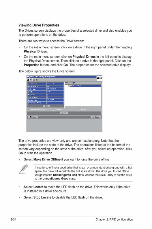
Viewing Drive PropertiesThe Drives screen displays the properties of a selected drive and also enables you to perform operations on the drive.
There are two ways to access the Drive screen:
• On the main menu screen, click on a drive in the right panel under the heading Physical Drives.
• On the main menu screen, click on Physical Drives in the left panel to display the Physical Drive screen. Then click on a drive in the right panel. Click on the Properties button, and click Go. The properties for the selected drive displays.
The below figure shows the Drive screen.
The drive properties are view-only and are self-explanatory. Note that the properties include the state of the drive. The operations listed at the bottom of the screen vary depending on the state of the drive. After you select an operation, click Go to start the operation.
• Select Make Drive Offline if you want to force the drive offline.
If you force offline a good drive that is part of a redundant drive group with a hot spare, the drive will rebuild to the hot spare drive. The drive you forced offline will go into the Unconfigured Bad state. Access the BIOS utility to set the drive to the Unconfigured Good state.
• Select Locate to make the LED flash on the drive. This works only if the drive is installed in a drive enclosure.
• Select Stop Locate to disable the LED flash on the drive.

ASUS PIKE 2108 2-35
If the drive state is Unconfigured Good, four additional operations appear on this screen:
• Select Make Global HSP to make a global hot spare, available to all of the virtual drives.
• Select Enclosure Affinity so if there are drive failures present on a split backplane configuration, then the hot spare will be used first on the backplane side that it resides in.
• Select Make Unconf Bad to make the drive state to become Unconfigured Bad.
• Select Prepare Removal to prepare the drive for removal from the enclosure.
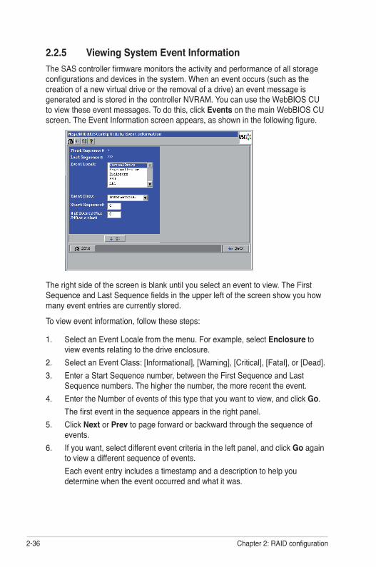
2-36 Chapter 2: RAID configuration
2.2.5 Viewing System Event InformationThe SAS controller firmware monitors the activity and performance of all storage configurations and devices in the system. When an event occurs (such as the creation of a new virtual drive or the removal of a drive) an event message is generated and is stored in the controller NVRAM. You can use the WebBIOS CU to view these event messages. To do this, click Events on the main WebBIOS CU screen. The Event Information screen appears, as shown in the following figure.
The right side of the screen is blank until you select an event to view. The First Sequence and Last Sequence fields in the upper left of the screen show you how many event entries are currently stored.
To view event information, follow these steps:
1. Select an Event Locale from the menu. For example, select Enclosure to view events relating to the drive enclosure.
2. Select an Event Class: [Informational], [Warning], [Critical], [Fatal], or [Dead].3. Enter a Start Sequence number, between the First Sequence and Last
Sequence numbers. The higher the number, the more recent the event.4. Enter the Number of events of this type that you want to view, and click Go. The first event in the sequence appears in the right panel.5. Click Next or Prev to page forward or backward through the sequence of
events.6. If you want, select different event criteria in the left panel, and click Go again
to view a different sequence of events. Each event entry includes a timestamp and a description to help you
determine when the event occurred and what it was.
ASUS PIKE 2108 2-37
2.2.6 Managing ConfigurationsThis section includes information about maintaining and managing storage configurations.
Running a Consistency CheckYou should periodically run a consistency check on fault-tolerant virtual drives. A consistency check verifies that the redundancy data is correct and available for RAID 1, RAID 5, and RAID 10 arrays. To do this, follow these steps:
1. On the main WebBIOS CU screen, select a virtual drive.2. When the Virtual Drive screen appears, select CC in the lower left panel, and
click Go.3. Click Yes to continue. The consistency check begins.
If the WebBIOS CU finds a difference between the data and the parity value on the redundant drive group, it assumes that the data is accurate and automatically corrects the parity value. Be sure to back up the data before running a consistency check if you think the data may be corrupted.
Deleting a Virtual DriveYou can delete any virtual drive on the controller if you want to reuse that space for a new virtual drive. The WebBIOS CU provides a list of configurable drive groups where there is a space to configure. If multiple virtual drives are defined on a single drive group, you can delete a virtual drive without deleting the whole drive group.
Back up any data that you want to keep before you delete the virtual drive.
To delete a virtual drive, follow these steps:
1. On the main WebBIOS CU screen, select a virtual drive.2. When the Virtual Drive screen appears, select Delete in the bottom panel
under the heading Operations, and click Go.3. When the message appears, confirm that you want to delete the virtual drive.
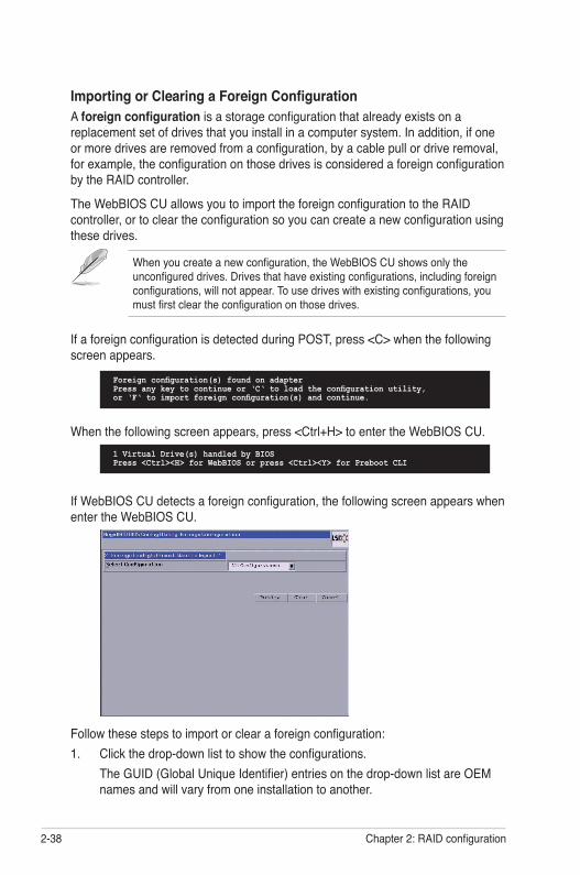
2-38 Chapter 2: RAID configuration
Importing or Clearing a Foreign ConfigurationA foreign configuration is a storage configuration that already exists on a replacement set of drives that you install in a computer system. In addition, if one or more drives are removed from a configuration, by a cable pull or drive removal, for example, the configuration on those drives is considered a foreign configuration by the RAID controller.
The WebBIOS CU allows you to import the foreign configuration to the RAID controller, or to clear the configuration so you can create a new configuration using these drives.
When you create a new configuration, the WebBIOS CU shows only the unconfigured drives. Drives that have existing configurations, including foreign configurations, will not appear. To use drives with existing configurations, you must first clear the configuration on those drives.
Foreign configuration(s) found on adapterPress any key to continue or ‘C‘ to load the configuration utility,or ‘F‘ to import foreign configuration(s) and continue.
If WebBIOS CU detects a foreign configuration, the following screen appears when enter the WebBIOS CU.
If a foreign configuration is detected during POST, press <C> when the following screen appears.
Follow these steps to import or clear a foreign configuration:1. Click the drop-down list to show the configurations. The GUID (Global Unique Identifier) entries on the drop-down list are OEM
names and will vary from one installation to another.
1 Virtual Drive(s) handled by BIOSPress <Ctrl><H> for WebBIOS or press <Ctrl><Y> for Preboot CLI
When the following screen appears, press <Ctrl+H> to enter the WebBIOS CU.
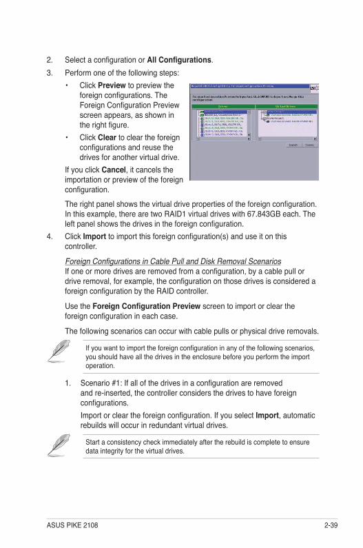
ASUS PIKE 2108 2-39
3. Perform one of the following steps: • Click Preview to preview the
foreign configurations. The Foreign Configuration Preview screen appears, as shown in the right figure.
• Click Clear to clear the foreign configurations and reuse the drives for another virtual drive.
If you click Cancel, it cancels the importation or preview of the foreign configuration.
The right panel shows the virtual drive properties of the foreign configuration. In this example, there are two RAID1 virtual drives with 67.843GB each. The left panel shows the drives in the foreign configuration.
4. Click Import to import this foreign configuration(s) and use it on this controller.
Foreign Configurations in Cable Pull and Disk Removal ScenariosIf one or more drives are removed from a configuration, by a cable pull or drive removal, for example, the configuration on those drives is considered a foreign configuration by the RAID controller.
Use the Foreign Configuration Preview screen to import or clear the foreign configuration in each case.
The following scenarios can occur with cable pulls or physical drive removals.
If you want to import the foreign configuration in any of the following scenarios, you should have all the drives in the enclosure before you perform the import operation.
1. Scenario #1: If all of the drives in a configuration are removed and re-inserted, the controller considers the drives to have foreign configurations.
Import or clear the foreign configuration. If you select Import, automatic rebuilds will occur in redundant virtual drives.
Start a consistency check immediately after the rebuild is complete to ensure data integrity for the virtual drives.
2. Select a configuration or All Configurations.
2-40 Chapter 2: RAID configuration
2. Scenario #2: If some of the drives in a configuration are removed and re-inserted, the controller considers the drives to have foreign configurations.
Import or clear the foreign configuration. If you select Import, automatic rebuilds will occur in redundant virtual drives.
Start a consistency check immediately after the rebuild is complete to ensure data integrity for the virtual drives.
3. Scenario #3: If all the drives in a virtual drive are removed, but at different times, and re-inserted, the controller considers the drives to have foreign configurations.
Import or clear the foreign configuration. If you select Import, all drives that were pulled before the virtual drive became offline will be imported and then automatically rebuilt. Automatic rebuilds will occur in redundant virtual drives.
4. Scenario #4: If the drives in a non-redundant virtual drive are removed, the controller considers the drives to have foreign configurations.
Import or clear the foreign configuration. No rebuilds will occur after the import operation because there is no redundant data to rebuild the drives with.
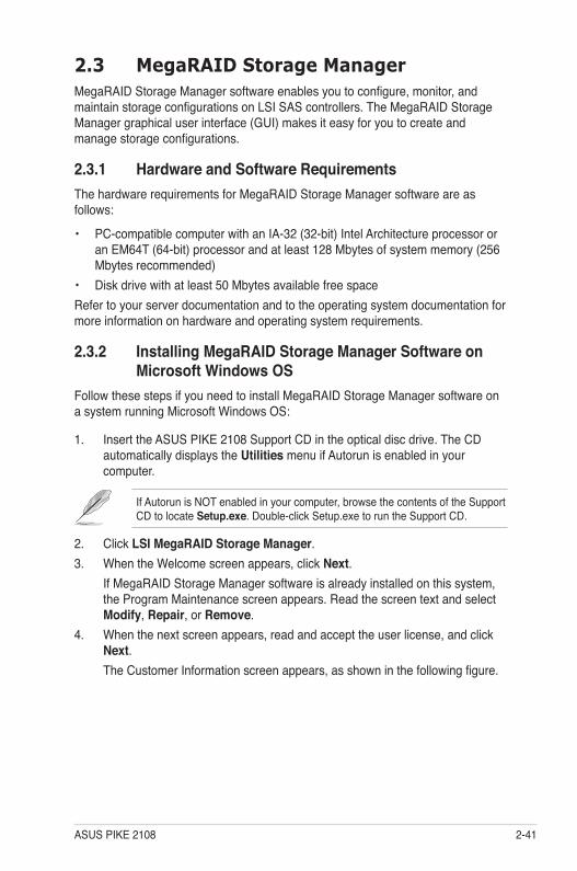
ASUS PIKE 2108 2-41
2.3 MegaRAID Storage ManagerMegaRAID Storage Manager software enables you to configure, monitor, and maintain storage configurations on LSI SAS controllers. The MegaRAID Storage Manager graphical user interface (GUI) makes it easy for you to create and manage storage configurations.
2.3.1 Hardware and Software RequirementsThe hardware requirements for MegaRAID Storage Manager software are as follows:
• PC-compatible computer with an IA-32 (32-bit) Intel Architecture processor or an EM64T (64-bit) processor and at least 128 Mbytes of system memory (256 Mbytes recommended)
• Disk drive with at least 50 Mbytes available free space Refer to your server documentation and to the operating system documentation for more information on hardware and operating system requirements.
2.3.2 Installing MegaRAID Storage Manager Software on Microsoft Windows OS
Follow these steps if you need to install MegaRAID Storage Manager software on a system running Microsoft Windows OS:
1. Insert the ASUS PIKE 2108 Support CD in the optical disc drive. The CD automatically displays the Utilities menu if Autorun is enabled in your computer.
If Autorun is NOT enabled in your computer, browse the contents of the Support CD to locate Setup.exe. Double-click Setup.exe to run the Support CD.
2. Click LSI MegaRAID Storage Manager.3. When the Welcome screen appears, click Next. If MegaRAID Storage Manager software is already installed on this system,
the Program Maintenance screen appears. Read the screen text and select Modify, Repair, or Remove.
4. When the next screen appears, read and accept the user license, and click Next.
The Customer Information screen appears, as shown in the following figure.
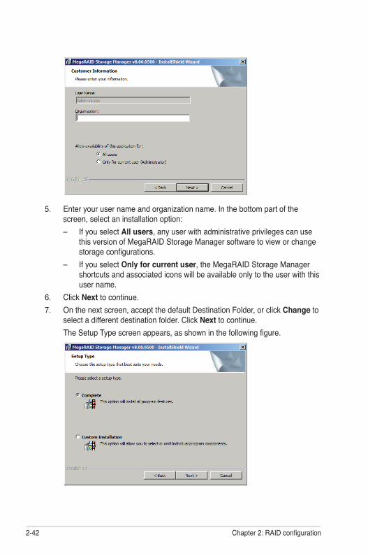
2-42 Chapter 2: RAID configuration
5. Enter your user name and organization name. In the bottom part of the screen, select an installation option:– If you select All users, any user with administrative privileges can use
this version of MegaRAID Storage Manager software to view or change storage configurations.
– If you select Only for current user, the MegaRAID Storage Manager shortcuts and associated icons will be available only to the user with this user name.
6. Click Next to continue.7. On the next screen, accept the default Destination Folder, or click Change to
select a different destination folder. Click Next to continue. The Setup Type screen appears, as shown in the following figure.

ASUS PIKE 2108 2-43
8. Select one of the Setup options. The options are fully explained in the screen text.– Normally, you would select Complete if you are installing MegaRAID
Storage Manager software on a server.– Select Custom Installation if you want to select individual program
components.9. Click Next to continue. If you selected Custom Installation as your setup option, the second Setup
Type screen appears, as shown in the following figure. If you select Complete as your setup option, the Installation Wizard is ready
to install MSM. To begin installation, click on Install on the next screen that appears.
10. Select one of the custom setup options. The options are fully explained in the screen text.– Select Client if you are installing MegaRAID Storage Manager software
on a PC that will be used to view and configure servers over a network. To begin installation, click on Install on the next screen that appears.
– Select Server to install only those components required for remote server management. To begin installation, click on Install on the next screen that appears.
– Select StandAlone if you will use MegaRAID Storage Manager software to create and manage storage configurations on a standalone workstation. To begin installation, click on Install on the next screen that appears.
– Select Custom if you want to specify individual program features to install.
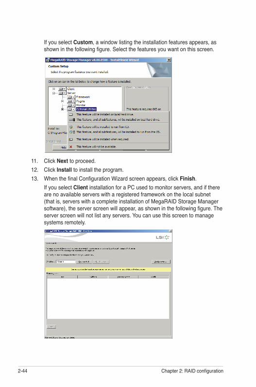
2-44 Chapter 2: RAID configuration
11. Click Next to proceed.12. Click Install to install the program.13. When the final Configuration Wizard screen appears, click Finish. If you select Client installation for a PC used to monitor servers, and if there
are no available servers with a registered framework on the local subnet (that is, servers with a complete installation of MegaRAID Storage Manager software), the server screen will appear, as shown in the following figure. The server screen will not list any servers. You can use this screen to manage systems remotely.
If you select Custom, a window listing the installation features appears, as shown in the following figure. Select the features you want on this screen.
ASUS PIKE 2108 2-45
2.3.3 Installing MegaRAID Storage Manager Software for Linux
Follow these steps if you need to install MegaRAID Storage Manager software on a system running Red Hat Linux or SUSE Linux:
1. Copy the MSM_linux_installer...tar.gz file to a temporary folder.2. Untar the MSM_linux_installer...tar.gz file using the following command: tar -zxvf MSM_linux_installer...tar.gz A new disk directory is created.3. Go to the new disk directory.4. In the disk directory, find and read the readme.txt file.5. To start the installation, enter the following command: csh install.sh -a
If you select Client installation for a PC used to monitor servers, and if there are no available servers with a registered framework on the local subnet (that is, servers with a complete installation of MegaRAID Storage Manager software), the server screen appears. The server screen does not list any servers. You can use this screen to manage systems remotely.
2-46 Chapter 2: RAID configuration
2.3.4 Linux Error MessagesThe following messages may appear while you are installing MegaRAID Storage Manager software on a Linux system:
• More than one copy of MegaRAID Storage Manager software has been installed.
This message indicates that the user has installed more than one copy of MegaRAID Storage Manager software. (This can be done by using the rpm-force command to install the rpm file directly, which is not recommended, instead of using the install.sh file.) In such cases, the user must uninstall all the rpm files manually before installing MegaRAID Storage Manager software with the procedure listed previously.
• The version is already installed. This message indicates that the version of MegaRAID Storage Manager
software you are trying to install is already installed on the system.• The installed version is newer. This message indicates that a version of MegaRAID Storage Manager
software is already installed on the system, and it is a newer version than the version you are trying to install.
• Exiting installation. This is the message that appears when the installation is complete.• RPM installation failed. This message indicates that the installation failed for some reason. Additional
message text explains the cause of the failure.
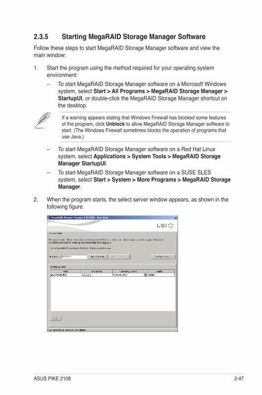
ASUS PIKE 2108 2-47
2.3.5 Starting MegaRAID Storage Manager SoftwareFollow these steps to start MegaRAID Storage Manager software and view the main window:
1. Start the program using the method required for your operating system environment:– To start MegaRAID Storage Manager software on a Microsoft Windows
system, select Start > All Programs > MegaRAID Storage Manager > StartupUI, or double-click the MegaRAID Storage Manager shortcut on the desktop.
If a warning appears stating that Windows Firewall has blocked some features of the program, click Unblock to allow MegaRAID Storage Manager software to start. (The Windows Firewall sometimes blocks the operation of programs that use Java.)
– To start MegaRAID Storage Manager software on a Red Hat Linux system, select Applications > System Tools > MegaRAID Storage Manager StartupUI.
– To start MegaRAID Storage Manager software on a SUSE SLES system, select Start > System > More Programs > MegaRAID Storage Manager.
2. When the program starts, the select server window appears, as shown in the following figure.
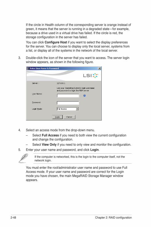
2-48 Chapter 2: RAID configuration
4. Select an access mode from the drop-down menu.– Select Full Access if you need to both view the current configuration
and change the configuration.– Select View Only if you need to only view and monitor the configuration.
5. Enter your user name and password, and click Login.
If the computer is networked, this is the login to the computer itself, not the network login.
You must enter the root/administrator user name and password to use Full Access mode. If your user name and password are correct for the Login mode you have chosen, the main MegaRAID Storage Manager window appears.
If the circle in Health column of the corresponding server is orange instead of green, it means that the server is running in a degraded state—for example, because a drive used in a virtual drive has failed. If the circle is red, the storage configuration in the server has failed.
You can click Configure Host if you want to select the display preferences for the server. You can choose to display only the local server, systems from a list, or display all of the systems in the network of the local server.
3. Double-click the icon of the server that you want to access. The server login window appears, as shown in the following figure.
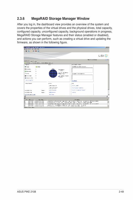
ASUS PIKE 2108 2-49
2.3.6 MegaRAID Storage Manager WindowAfter you log in, the dashboard view provides an overview of the system and covers the properties of the virtual drives and the physical drives, total capacity, configured capacity, unconfigured capacity, background operations in progress, MegaRAID Storage Manager features and their status (enabled or disabled), and actions you can perform, such as creating a virtual drive and updating the firmware, as shown in the following figure.
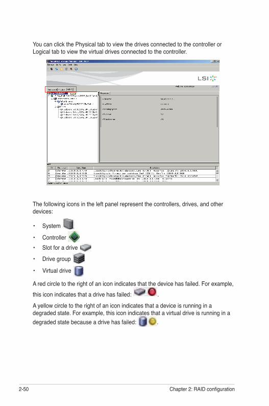
2-50 Chapter 2: RAID configuration
The following icons in the left panel represent the controllers, drives, and other devices:
• System
• Controller • Slot for a drive
• Drive group
• Virtual drive
A red circle to the right of an icon indicates that the device has failed. For example, this icon indicates that a drive has failed: .
A yellow circle to the right of an icon indicates that a device is running in a degraded state. For example, this icon indicates that a virtual drive is running in a degraded state because a drive has failed: .
You can click the Physical tab to view the drives connected to the controller or Logical tab to view the virtual drives connected to the controller.
ASUS PIKE 2108 2-51
Properties View PanelThe right panel of the MegaRAID Storage Manager window has the Properties tab that displays information about the selected device. For example, if a controller icon is selected in the left panel, the Properties tab lists information such as the controller name, NVRAM size, and device port count.
Event Log PanelThe lower part of the MegaRAID Storage Manager window displays the system event log entries. New event log entries appear during the session. Each entry has an ID, a timestamp and date, an error level indicating the severity of the event, and a brief description of the event.
Menu BarHere are brief descriptions of the main selections on the MegaRAID Storage Manager menu bar.
Manage MenuThe Manage menu has an Exit option for exiting from the MegaRAID Storage Manager software. It also has a Refresh option for updating the display in the MegaRAID Storage Manager window. (Refresh is seldom required; the display normally updates automatically.) The Manage menu options also include Check Consistency, Initialize, and Show Progress.
Go To MenuThe Go To menu is available when a controller, physical drive, or virtual disk is selected in the MegaRAID Storage Manager window. The Go To menu options vary depending on what type of device is selected in the left panel of the MegaRAID Storage Manager window. For example, the Scan Foreign Configuration option is available only when a controller is selected. The options also vary depending on the current state of the selected device. For example, if you select an offline physical drive, the Make Drive Online option will be available in the Go To menu.
Log MenuThe Log menu includes options for saving and clearing the message log.
Tools MenuOn the Tools menu you can select Configure Alerts to access the Event Configuration Notification screen, which you can use to set the alert delivery rules, event severity levels, exceptions, and email settings.
2-52 Chapter 2: RAID configuration
Help MenuOn the Help menu you can select Help > Contents to view the MegaRAID Storage Manager online help file. You can select Help > About MegaRAID Storage Manager to view version information for the MegaRAID Storage Manager software.
• When you use the MegaRAID Storage Manager online help, you may see a warning message that Internet Explorer has restricted the file from showing active content. If this warning appears, click on the active content warning bar and enable the active content.
• If you are using the Linux operating system, you must install Firefox® or Mozilla® for the MegaRAID Storage Manager online help to display.

3Chapter 3: Driver installation
This chapter provides instructions for installing the RAID drivers on different operating systems.
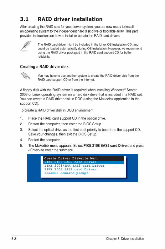
3-2 Chapter 3: Driver installation
3.1 RAID driver installationAfter creating the RAID sets for your server system, you are now ready to install an operating system to the independent hard disk drive or bootable array. This part provides instructions on how to install or update the RAID card drivers.
The RAID card driver might be included in the Linux OS installation CD, and could be loaded automatically during OS installation. However, we recommend using the RAID driver packaged in the RAID card support CD for better reliability.
Creating a RAID driver disk
You may have to use another system to create the RAID driver disk from the RAID card support CD or from the Internet.
A floppy disk with the RAID driver is required when installing Windows® Server 2003 or Linux operating system on a hard disk drive that is included in a RAID set. You can create a RAID driver disk in DOS (using the Makedisk application in the support CD).
To create a RAID driver disk in DOS environment:
1. Place the RAID card support CD in the optical drive.2. Restart the computer, then enter the BIOS Setup.3. Select the optical drive as the first boot priority to boot from the support CD.
Save your changes, then exit the BIOS Setup.4. Restart the computer.5. The Makedisk menu appears. SelectThe Makedisk menu appears. Select PIKE 2108 SAS2 card Driver, and press
<Enter> to enter the submenu.
Create Driver Diskette MenuPIKE 2108 SAS2 card DriverPIKE 2008/IMR SAS2 card DriverPIKE 2008 SAS2 card DriverFreeDOS command prompt

ASUS PIKE 2108 3-3
7. Place a blank, high-density floppy disk to the floppy disk drive.8. Press <Enter>.9. Follow screen instructions to create the driver disk.
6. Use the arrow keys to select the type of RAID driver disk you want to create.
PIKE 2108 SAS2 card DriverWindows XP 32 bitWindows XP 64 bitWindows Server 2003 32 bitWindows Server 2003 64 bitWindows Vista 32 bitWindows Vista 64 bitWindows Server 2008 32 bitWindows Server 2008 64 bitWindows 7 32 bitWindows 7 64 bitWindows Server 2008 R2 64 bitRHEL 3 UP9 32/64 bitRHEL 4 UP5 32/64 bitRHEL 4 UP6 32/64 bitRHEL 4 UP7 32/64 bitRHEL 4 UP8 32/64 bitRHEL 5 32/64 bitRHEL 5 UP2 32/64 bitRHEL 5 UP3 32/64 bitRHEL 5 UP4 32/64 bitRHEL 5 UP5 32/64 bitSLES 9 SP3 32 bit
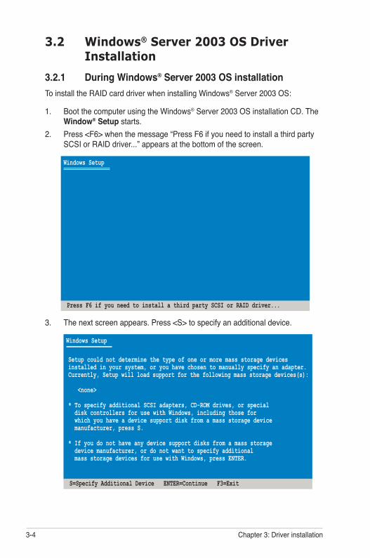
3-4 Chapter 3: Driver installation
3.2 Windows® Server 2003 OS Driver Installation
3.2.1 During Windows® Server 2003 OS installationTo install the RAID card driver when installing Windows® Server 2003 OS:
1. Boot the computer using the Windows® Server 2003 OS installation CD. The Window® Setup starts.
2. Press <F6> when the message “Press F6 if you need to install a third party SCSI or RAID driver...” appears at the bottom of the screen.
3. The next screen appears. Press <S> to specify an additional device.
Windows Setup
S=Specify Additional Device ENTER=Continue F3=Exit
Setup could not determine the type of one or more mass storage devicesinstalled in your system, or you have chosen to manually specify an adapter.Currently, Setup will load support for the following mass storage devices(s):
<none>
* To specify additional SCSI adapters, CD-ROM drives, or special disk controllers for use with Windows, including those for which you have a device support disk from a mass storage device manufacturer, press S.
* If you do not have any device support disks from a mass storage device manufacturer, or do not want to specify additional mass storage devices for use with Windows, press ENTER.
Windows Setup
Press F6 if you need to install a third party SCSI or RAID driver...
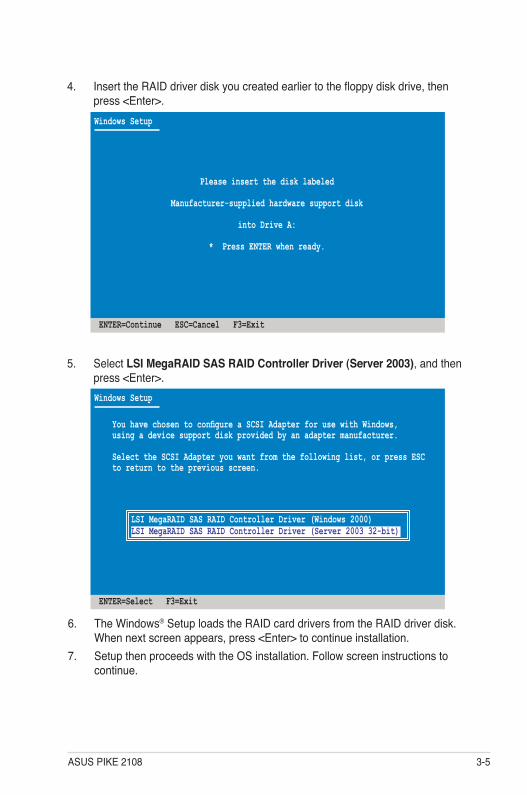
ASUS PIKE 2108 3-5
4. Insert the RAID driver disk you created earlier to the floppy disk drive, then press <Enter>.Windows Setup
ENTER=Continue ESC=Cancel F3=Exit
Please insert the disk labeled
Manufacturer-supplied hardware support disk
into Drive A:
* Press ENTER when ready.
5. Select LSI MegaRAID SAS RAID Controller Driver (Server 2003), and then press <Enter>.
6. The Windows® Setup loads the RAID card drivers from the RAID driver disk. When next screen appears, press <Enter> to continue installation.
7. Setup then proceeds with the OS installation. Follow screen instructions to continue.
Windows Setup
ENTER=Select F3=Exit
You have chosen to configure a SCSI Adapter for use with Windows,using a device support disk provided by an adapter manufacturer.
Select the SCSI Adapter you want from the following list, or press ESCto return to the previous screen.
LSI MegaRAID SAS RAID Controller Driver (Windows 2000)LSI MegaRAID SAS RAID Controller Driver (Server 2003 32-bit)
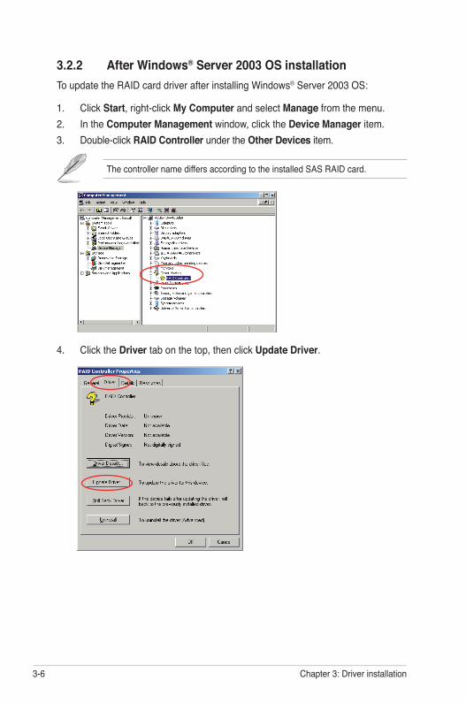
3-6 Chapter 3: Driver installation
3.2.2 After Windows® Server 2003 OS installationTo update the RAID card driver after installing Windows® Server 2003 OS:
1. Click Start, right-click My Computer and select Manage from the menu.2. In the Computer Management window, click the Device Manager item.3. Double-click RAID Controller under the Other Devices item.
4. Click the Driver tab on the top, then click Update Driver.
The controller name differs according to the installed SAS RAID card.
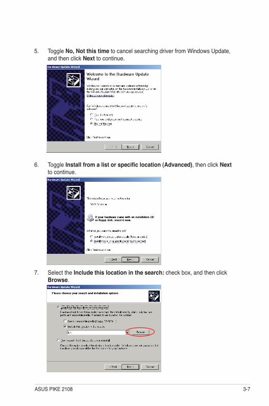
ASUS PIKE 2108 3-7
5. Toggle No, Not this time to cancel searching driver from Windows Update, and then click Next to continue.
6. Toggle Install from a list or specific location (Advanced), then click Next to continue.
7. Select the Include this location in the search: check box, and then click Browse.
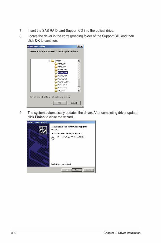
3-8 Chapter 3: Driver installation
7. Insert the SAS RAID card Support CD into the optical drive.8. Locate the driver in the corresponding folder of the Support CD, and then
click OK to continue.
9. The system automatically updates the driver. After completing driver update, click Finish to close the wizard.
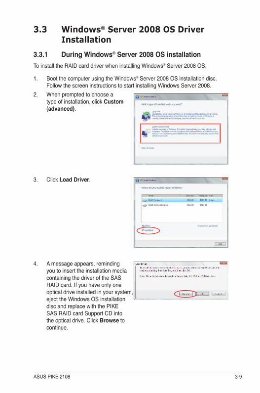
ASUS PIKE 2108 3-9
3. Click Load Driver.
4. A message appears, reminding you to insert the installation media containing the driver of the SAS RAID card. If you have only one optical drive installed in your system, eject the Windows OS installation disc and replace with the PIKE SAS RAID card Support CD into the optical drive. Click Browse to continue.
3.3 Windows® Server 2008 OS Driver Installation
3.3.1 During Windows® Server 2008 OS installationTo install the RAID card driver when installing Windows® Server 2008 OS:
1. Boot the computer using the Windows® Server 2008 OS installation disc. Follow the screen instructions to start installing Windows Server 2008.
2. When prompted to choose a type of installation, click Custom (advanced).
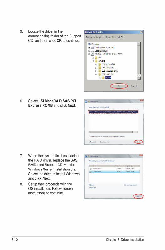
3-10 Chapter 3: Driver installation
5. Locate the driver in the corresponding folder of the Support CD, and then click OK to continue.
6. Select LSI MegaRAID SAS PCI Express ROMB and click Next.
7. When the system finishes loading the RAID driver, replace the SAS RAID card Support CD with the Windows Server installation disc. Select the drive to install Windows and click Next.
8. Setup then proceeds with the OS installation. Follow screen instructions to continue.
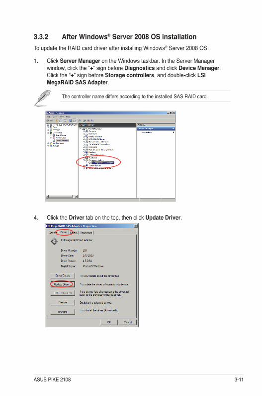
ASUS PIKE 2108 3-11
4. Click the Driver tab on the top, then click Update Driver.
3.3.2 After Windows® Server 2008 OS installationTo update the RAID card driver after installing Windows® Server 2008 OS:
1. Click Server Manager on the Windows taskbar. In the Server Manager window, click the “+” sign before Diagnostics and click Device Manager. Click the “+” sign before Storage controllers, and double-click LSI MegaRAID SAS Adapter.
The controller name differs according to the installed SAS RAID card.
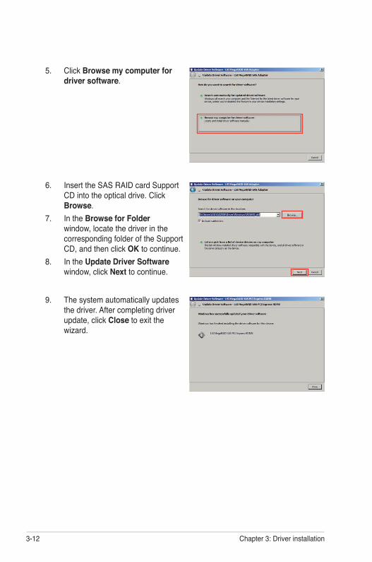
3-12 Chapter 3: Driver installation
5. Click Browse my computer for driver software.
9. The system automatically updates the driver. After completing driver update, click Close to exit the wizard.
6. Insert the SAS RAID card Support CD into the optical drive. Click Browse.
7. In the Browse for Folder window, locate the driver in the corresponding folder of the Support CD, and then click OK to continue.
8. In the Update Driver Software window, click Next to continue.
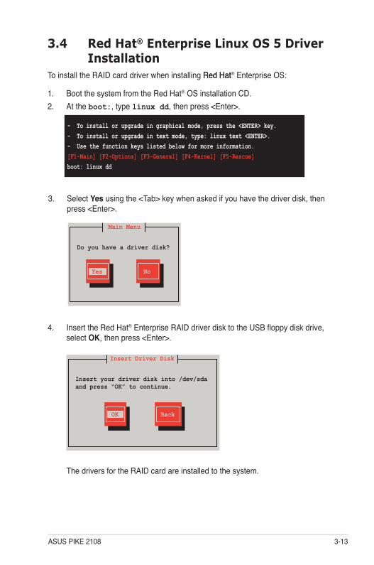
ASUS PIKE 2108 3-13
3.4 Red Hat® Enterprise Linux OS 5 Driver Installation
To install the RAID card driver when installing Red Hat Red Hat® Enterprise OS:
1. Boot the system from the Red Hat® OS installation CD.2. At the boot:, type linux dd, then press <Enter>.
- To install or upgrade in graphical mode, press the <ENTER> key.- To install or upgrade in text mode, type: linux text <ENTER>.- Use the function keys listed below for more information.[F1-Main] [F2-Options] [F3-General] [F4-Kernel] [F5-Rescue]boot: linux dd
3. Select Yes using the <Tab> key when asked if you have the driver disk, then press <Enter>.
Main Menu
Do you have a driver disk?
Yes No
4. Insert the Red Hat® Enterprise RAID driver disk to the USB floppy disk drive, select OK, then press <Enter>.
The drivers for the RAID card are installed to the system.
Insert Driver Disk
Insert your driver disk into /dev/sda and press “OK” to continue.
OK Back
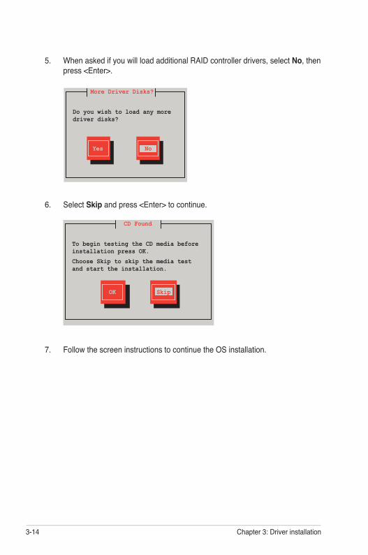
3-14 Chapter 3: Driver installation
5. When asked if you will load additional RAID controller drivers, select No, then press <Enter>.
7. Follow the screen instructions to continue the OS installation.
More Driver Disks?
Do you wish to load any more driver disks?
Yes No
6. Select Skip and press <Enter> to continue.
CD Found
To begin testing the CD media before installation press OK.
Choose Skip to skip the media test and start the installation.
OK Skip
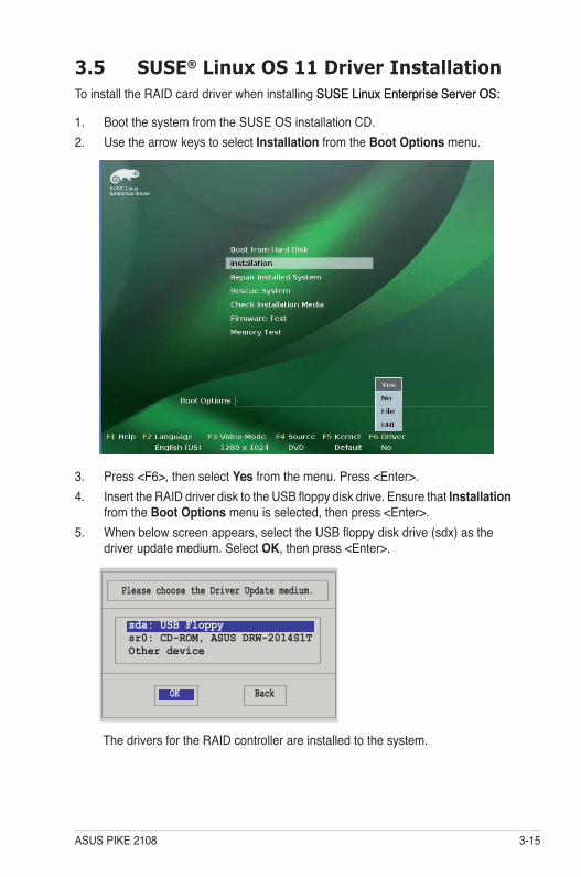
ASUS PIKE 2108 3-15
3.5 SUSE® Linux OS 11 Driver InstallationTo install the RAID card driver when installing SUSE Linux Enterprise Server OS: SUSE Linux Enterprise Server OS:
1. Boot the system from the SUSE OS installation CD.2. Use the arrow keys to select Installation from the Boot Options menu.
3. Press <F6>, then select Yes from the menu. Press <Enter>.4. Insert the RAID driver disk to the USB floppy disk drive. Ensure that Installation
from the Boot Options menu is selected, then press <Enter>.5. When below screen appears, select the USB floppy disk drive (sdx) as the
driver update medium. Select OK, then press <Enter>.
The drivers for the RAID controller are installed to the system.
Please choose the Driver Update medium.
OK Back
sda: USB Floppysr0: CD-ROM, ASUS DRW-2014S1TOther device

3-16 Chapter 3: Driver installation
ASUS contact information
ASUSTeK COMPUTER INC. (Taiwan)Address 15 Li-Te Road, Peitou, Taipei, Taiwan 11259Telephone +886-2-2894-3447Fax +886-2-2890-7798E-mail [email protected] site http://www.asus.com.tw
Technical SupportTelephone +886-2-2894-3447 (0800-093-456)Online Support http://support.asus.com/techserv/techserv.aspx
ASUSTeK COMPUTER INC. (China)Address No.508, Chundong Road, Xinzhuang Industrial Zone, Minhang District, Shanghai, China.Telephone +86-21-5442-1616Fax +86-21-5442-0099Web site http://www.asus.com.cn
Technical SupportTelephone +86-21-3407-4610 (800-820-6655)Online Support http://support.asus.com/techserv/techserv.aspx
ASUS COMPUTER INTERNATIONAL (America)Address 800 Corporate Way, Fremont, CA 94539, USAFax +1-510-608-4555Web site http://usa.asus.com
Technical SupportSupport fax +1-812-284-0883General support +1-812-282-2787Online support http://support.asus.com/techserv/techserv.aspx
ASUS COMPUTER GmbH (Germany and Austria)Address Harkort Str. 21-23, 40880 Ratingen, GermanyFax +49-2102-959911Web site http://www.asus.deOnline contact http://www.asus.de/sales
Technical SupportTelephone +49-1805-010923*Support Fax +49-2102-959911Online support http://support.asus.com/techserv/techserv.aspx
* EUR 0.14/minute from a German fixed landline; EUR 0.42/minute from a mobile phone.
EC D
ecla
ratio
n of
Con
form
ity
We,
the
unde
rsig
ned,
M
anuf
actu
rer:
ASUS
Tek
COM
PUTE
R IN
C.
Addr
ess,
City
: No
. 150
, LI-T
E RD
., PE
ITO
U, T
AIPE
I 112
, TAI
WAN
R.O
.C.
Coun
try:
TAIW
ANAu
thor
ized
repr
esen
tativ
e in
Eur
ope:
AS
US C
OM
PUTE
R G
mbH
Addr
ess,
City
: HA
RKO
RT S
TR. 2
1-23
, 408
80 R
ATIN
GEN
Coun
try:
G
ERM
ANY
decl
are
the
follo
win
g ap
para
tus:
Pr
oduc
t nam
e :
PIKE
Car
d
Mod
el n
ame
: PI
KE 2
108
conf
orm
with
the
esse
ntia
l req
uire
men
ts o
f the
follo
win
g di
rect
ives
: 20
04/1
08/E
C-EM
C Di
rect
ive
EN
5502
2:20
06+A
1:20
07
EN 6
1000
-3-2
:200
6 E
N 55
013:
2001
+A1:
2003
+A2:
2006
EN
5502
4:19
98+A
1:20
01+A
2:20
03
EN
6100
0-3-
3:20
08
EN
5502
0:20
07
1999
/5/E
C-R
&TTE
Dire
ctiv
e E
N 30
0 32
8 V1
.7.1
(200
6-05
) E
N 30
0 44
0-1
V1.4
.1(2
008-
05)
EN
300
440-
2 V1
.2.1
(200
8-03
) E
N 30
1 51
1 V9
.0.2
(200
3-03
) E
N 30
1 90
8-1
V3.2
.1(2
007-
05)
EN
301
908-
2 V3
.2.1
(200
7-05
) E
N 30
1 89
3 V1
.4.1
(200
5-03
) E
N 50
360:
2001
E
N 50
371:
2002
E
N 62
311:
2008
E
N 50
385:
2002
EN
301
489-
1 V1
.8.1
(200
8-04
) E
N 30
1 48
9-3
V1.4
.1(2
002-
08)
EN
301
489-
4 V1
.3.1
(200
2-08
) E
N 30
1 48
9-7
V1.3
.1(2
005-
11)
EN
301
489-
9 V1
.4.1
(200
7-11
) E
N 30
1 48
9-17
V1.
3.2(
2008
-04)
E
N 30
1 48
9-24
V1.
4.1(
2007
-09)
E
N 30
2 32
6-2
V1.2
.2(2
007-
06)
EN
302
326-
3 V1
.3.1
(200
7-09
) E
N 30
1 35
7-2
V1.3
.1(2
006-
05)
2006
/95/
EC-L
VD D
irect
ive
EN
6095
0-1:
2001
+A11
:200
4
EN 6
0950
-1:2
006
EN6
0065
:200
2+A1
:200
6
EN
6095
0-1:
2006
+A11
:200
9
2009
/125
/EC-
ErP
Dire
ctiv
eRe
gula
tion
(EC)
No.
127
5/20
08
EN
6230
1:20
05
Regu
latio
n (E
C) N
o. 6
42/2
009
EN
6230
1:20
05
Regu
latio
n (E
C) N
o. 2
78/2
009
EN
6230
1:20
05
CE m
arki
ng
Decl
arat
ion
Date
: Oct
. 28,
201
0 Ye
ar to
beg
in a
ffixi
ng C
E m
arki
ng:2
010
Posit
ion
: C
EONa
me
: Je
rry
She
n
Sign
atur
e :_
____
____
_
(EC
conf
orm
it y m
arkin
g)
DEC
LAR
ATI
ON
OF
CO
NFO
RM
ITY
Per F
CC P
art 2
Sec
tion
2. 1
077(
a)
R
espo
nsib
le P
arty
Nam
e:
Asu
s Com
pute
r In
tern
atio
nal
A
ddre
ss:
800
Cor
pora
te W
ay, F
rem
ont,
CA
945
39.
Ph
one/
Fax
No:
(5
10)7
39-3
777/
(510
)608
-455
5
here
by d
ecla
res t
hat t
he p
rodu
ct
Prod
uct N
ame
: PIK
E Ca
rd
Mod
el N
umbe
r : P
IKE
2108
Co
nfor
ms t
o th
e fo
llow
ing
spec
ifica
tions
:
FCC
Part
15, S
ubpa
rt B,
Uni
nten
tiona
l Rad
iato
rs
FCC
Part
15, S
ubpa
rt C,
Inte
ntio
nal R
adia
tors
FC
C Pa
rt 15
, Sub
part
E, In
tent
iona
l Rad
iato
rs
Supp
lem
enta
ry In
form
atio
n:
This
devi
ce c
ompl
ies
with
par
t 15
of th
e FC
C Ru
les.
Ope
ratio
n is
subj
ect t
o th
e fo
llow
ing
two
cond
ition
s: (1
) Th
is de
vice
may
not
cau
se h
arm
ful
inte
rfere
nce,
and
(2)
this
devi
ce m
ust
acce
pt a
ny i
nter
fere
nce
rece
ived
, in
clud
ing
inte
rfere
nce t
hat m
ay ca
use u
ndes
ired
oper
atio
n.
Re
pres
enta
tive
Pers
on’s
Nam
e :
St
eve
Cha
ng /
Pres
iden
t
Sign
atur
e :
D
ate
:
O
ct. 2
9, 2
010