pilot tube microtunneling: profile of an emerging … tube microtunneling: profile of an emerging...
TRANSCRIPT
Pilot Tube Microtunneling:
Profile of an Emerging Industry
by
Vamseedhar Gottipati
A Thesis Presented in Partial Fulfillment
of the Requirements for the Degree
Master of Science
Approved September 2011 by the
Graduate Supervisory Committee:
Jason S. Lueke, Chair
Samuel T. Ariaratnam
Allan Chasey
ARIZONA STATE UNIVERSITY
December 2011

i
ABSTRACT
Trenchless technologies have emerged as a viable alternative to traditional
open trench methods for installing underground pipelines and conduits. Pilot Tube
Microtunneling, also referred to as the pilot tube system of microtunneling,
guided auger boring, or guided boring method, is a recent addition to the family of
trenchless installation methods. Pilot tube microtunneling originated in Japan and
Europe, and was introduced to the United States in the year 1995 (Boschert 2007).
Since then this methodology has seen increased utilization across North America
particularity in municipal markets for the installation of gravity sewers. The
primary reason contributing to the growth of pilot tube microtunneling is the
technology's capability of installing pipes at high precision in terms of line and
grade, in a wide range of ground conditions using relatively inexpensive
equipment.
The means and methods, applicability, capabilities and limitations of pilot
tube microtunneling are well documented in published literature through many
project specific case studies. However, there is little information on the
macroscopic level regarding the technology and industry as a whole. With the
increasing popularity of pilot tube microtunneling, there is an emerging need to
address the above issues. This research effort surveyed 22 pilot tube
microtunneling contractors across North America to determine the current
industry state of practice with the technology. The survey examined various topics
including contractor profile and experience; equipment, methods, and pipe

ii
materials utilized; and issues pertaining to project planning and construction risks
associated with the pilot tube method.
The findings of this research are based on a total of 450 projects
completed with pilot tube microtunneling between 2006 and 2010. The
respondents were diverse in terms of their experience with PTMT, ranging from
two to 11 years. A majority of the respondents have traditionally provided
services with other trenchless technologies. As revealed by the survey responses,
PTMT projects grew by 110% between the years 2006 and 2010. It was found
that almost 72% of the 450 PTMT projects completed between 2006 and 2010 by
the respondents were for sanitary sewers. Installation in cobbles and boulders was
rated as the highest risk by the contractors.

iii
To Mom, Dad, Dharani and Akhila

iv
ACKNOWLEDGMENTS
I am indebted to my advisor Dr. Jason Lueke for his constant advice and
guidance through this research. This effort would not have been possible without
his constant support and encouragement. I thank my committee members Dr.
Samuel Ariaratnam and Dr. Allan Chasey for their support and encouragement. I
thank all the researchers at the Center for Research in Underground Systems and
Technology (CRUST) for their encouragement. I thank all the graduate students
and faculty members at the Del E. Webb School of Construction for making my
stay at the school memorable. Thanks are due to Mr. Jeff Boschert from the
National Clay Pipe Institute (NCPI) for supporting this research. Many thanks are
due to all the contractors that took out their valuable time to fill out the survey
questionnaires.

v
TABLE OF CONTENTS
Page
LIST OF TABLES ..................................................................................................... vii
LIST OF FIGURES .................................................................................................. viii
CHAPTER
1 INTRODUCTION .................................................................................. 1
2 LITERATURE REVIEW ...................................................................... 4
2.1 Trenchless Technology ................................................................. 4
2.1.1 Trenchless Versus Open Trench ..................................... 10
2.2 Introduction to Pilot Tube Microtunneling (PTMT) ................ 14
2.3 PTMT Methodology and Equipment ......................................... 16
2.3.1 Site Preparation and Set-up ............................................. 16
2.3.2 Three-Step Method .......................................................... 18
2.3.3 Two-Step Method ............................................................ 30
2.3.4 Modified Three-Step Method ......................................... 32
2.3.5 Hybrid Methods ............................................................... 35
2.4 Advantages and Limitations of PTMT ....................................... 37
2.5 Case Studies ................................................................................. 38
2.5.1 City of Bloomington Project ........................................... 39
2.5.2 Two Projects using PTMT-HDD Hybrid Methods ........ 42
2.5.3 St. Louis Project .............................................................. 45
3 SURVEY .............................................................................................. 49
3.1 Survey Methodology .................................................................. 49

vi
CHAPTER Page
3.2 Results ........................................................................................... 51
3.2.1 Company Profile.............................................................. 52
3.2.2 Project Characteristics ..................................................... 62
3.2.3 Project Planning and Construction Risks ....................... 69
4 CONCLUSION .................................................................................... 79
4.1 Summary of Results .................................................................... 80
4.2 Areas for Future Research ........................................................... 83
4.2.1 Practice of PTMT Projects .............................................. 83
4.2.1 Costs and Productivity .................................................... 84
4.2.3 Comparison with Other Methods of Pipe Installation .... 85
REFERENCES ........................................................................................................ 86
APPENDIX
A SURVEY QUESTIONNAIRE ....................................................... 91
B LIST OF RESPONDENTS .............................................................. 95

vii
LIST OF TABLES
Table Page
1. Comparison of the Capabilities of Various Trenchless Methods .......... 8
2. Applicability of Various Trenchless Methods in Different Soil
Conditions ........................................................................................... 9
3. Distribution of the Projects Executed by the Respondents Using
Various Technologies between the Years 2006 and 2010 ............. 57
4. Distribution of the Respondents by their Individual Share of PTMT
Projects ............................................................................................... 58
5. Distribution of Respondents by Percentage PTMT Share and Client .. 59
6. Distribution of Respondents by Their Role on PTMT Projects ........... 60
7. Distribution of the Respondents by ownership of Jacking Frames ...... 61
8. Breakdown of Work Obtained From Sanitary Sewer Type .................. 63
9. Breakdown of PTMT Work Obtained Through Competitive
Bidding .............................................................................................. 65
10. Breakdown of the Contractors Based on the Time Spent in Various
Phases .................................................................................................. 70
11. Risk Factors and Conditions .................................................................. 72

viii
LIST OF FIGURES
Figure Page
1. Family of Trenchless Technologies ...................................................... 7
2. Placing the Pre-Built Shaft Support ................................................... 17
3. First Step of the Three-Step PTMT Method ..................................... 19
4. Pilot Tubes Staged on the Site ............................................................ 20
5. LED Illuminated Target Mounted Inside the Steering Head ........... 21
6. Guidance System with its Components .............................................. 22
7. Various Types of Steering Heads and the Supporting Equipment ... 23
8. Jacking Frame ...................................................................................... 24
9. Second Step of the Three-Step Method.............................................. 26
10. Reaming Head Welded on the Auger Casing .................................... 27
11. Auger Casings with Augers ................................................................ 28
12. Third Step of the Three-Step Method ................................................ 29
13. Second Step of the Two-Step Method................................................ 30
14. Auger Casings inside the Product Pipe Sections ............................... 31
15. Third Step of the Modified Three-Step Method ................................ 33
16. Powered Cutting Head (PCH) ............................................................ 34
17. Powered Reaming Head (PRH) .......................................................... 34
18. Area of Activity by Survey Respondents ........................................... 53
19. Share of Trenchless Project Executed by Various Technologies ..... 56
20. Distribution of the Jacking Machines Owned by the Respondents .. 61
21. Factors Affecting Productivity ........................................................... 76

1
CHAPTER 1
INTRODUCTION
It is estimated that water and wastewater utilities in the United States are
responsible for approximately 800,000 miles of water pipelines and 600,000 to
800,000 miles of wastewater pipelines (USGAO 2004). The American Society of
Civil Engineers reported in 2009 that the nation’s water and wastewater
infrastructure is in a poor state and awarded them the grades D and D-
respectively, noting that many of the distribution networks are ageing and need
replacement (ASCE 2009). The water infrastructure network estimated that the
capital needs for water and wastewater industries together is around $740 billion
for the period 2000-2019 (USGAO 2004). These statistics emphasize that there is
an urgent need for replacing or rehabilitating deteriorating underground
infrastructure.
The traditional method of installing underground pipelines has been to
dig/trench along the alignment of the pipeline and manually install the pipes and
joints. This method is often referred to as open-cut method or open trench
method. For the purpose of this thesis, the method is henceforth referred to as
open trench. By the virtue of its practice, open trench requires many ancillary
processes such as detour of roads, storage of excavated materials on the site,
backfilling and compaction, ground water management, and restoration of
surfaces post the installation. These activities that are additional to the main
process of installing pipes consume time, money and disrupt the movement of
vehicles and pedestrians.

2
As an alternative to open trench, several methods have emerged over the
years that minimize trench work. These technologies are together referred to as
trenchless technologies. Trenchless technologies are characterized as those that
minimize the need for personnel to be working in the trench below ground level.
Pilot Tube Microtunneling (PTMT) is a recent entrant to the family of trenchless
methods. The technology evolved combining the techniques of three other
trenchless methods namely Microtunneling, Horizontal Directional Drilling
(HDD) and Auger Boring. This method was initially used to install small diameter
pipes and service/house laterals. However, PTMT has evolved to large diameter
and main stream installations over the years. One of the main advantages of this
method is its ability to perform installations at high levels of accuracy on line and
grade. PTMT was introduced to the United States in the 1990s (Boyce and Camp
2008), and has since seen increase in popularity.
The means and methods of PTMT, its capabilities, advantages and
limitations are well documented through published sources. However, there is
little literature available on the technology’s industry trends, business practices,
and contractor’s perspectives of the technology. With the growing popularity and
acceptance of PTMT as an affordable and efficient trenchless technique, there is a
need to address the above mentioned areas. It was realized that the best way to
obtain this information was by contacting the contractors directly working with
the technology. A survey was designed at Arizona State University in
coordination with equipment manufacturers, industry consultants and contractors.
The survey aimed at gathering information related to industry practices with

3
technology, the technology’s abilities and applicability, business practices, and
risks, among others. Starting in September 2010, surveys were sent to PTMT
contractors across the United States and Canada. Twenty two survey responses
were received as on Feb 2011.
Chapter 2 presents the background for this research. Chapter 2 discusses
trenchless technology in general, various methods, comparison of trenchless
methods with the open trench method, background of PTMT, the variants and
hybrid methods of the technology, equipment used, and case studies of three
projects that were executed using a PTMT method. Chapter 3 discusses the
techniques used in developing the survey and the results gathered from the
compiled data. The thesis ends by presenting conclusions and recommendations
for future work in Chapter 4.

4
CHAPTER 2
LITERATURE REVIEW
The first section of this chapter presents a general overview of trenchless
technology, classification of the various technologies available, evaluation of their
applicability and capabilities, and comparison of trenchless technology with the
traditional open trench method. The next section discusses the origins of Pilot
Tube Microtunneling (PTMT), and the technology’s applicability and capabilities.
The third section presents the methodology of the three variants of PTMT and
discussion on the equipment used with PTMT. The third section also focuses on
the methodologies of the three hybrid methods where PTMT is used in
conjunction with other trenchless technologies. The fourth section discusses the
advantages and limitations of the technology. The final section of this chapter
presents three case studies of projects that used PTMT.
2.1 Trenchless Technology
Trenchless technologies have evolved as an attractive alternative to the
traditional open trench method. The International Society for Trenchless
Technology (ISTT) defines Trenchless Technology (TT) as “Methods for utility
and other line installation, rehabilitation, replacement, renovation, repair,
inspection, location and leak detection, with minimum excavation from the
ground surface” (ISTT 2011).
It is a general agreement that TT traces its roots back to Europe. The
trenchless technology industry was officially established in the United States in
the year 1990 through the creation of the North American Society for Trenchless
5
Technology (NASTT). However, trenchless methods have been in use for over
100 years. For example, the Northern Pacific Railroad Company used pipe
jacking techniques as early as the 1860s (Ariaratnam et. al. 1999). Trenchless
industry has witnessed rapid growth in the past two decades. Trenchless methods
have gained a share of 20% by cost in pipe installation and renewal for utility
services, according to North American cost indices for the period 1988 to 1998
(Najafi and Gokhale 2005). Many new technologies have evolved over the years
and rapid advancements have taken place with the existing technologies. PTMT is
considered as the most recent entrant to the family of trenchless technologies. The
timelines for some of the trenchless methods when they were first used are as
follows: auger boring (1940), impact moling (1962), directional drilling (1971),
microtunneling (1973), and pipe bursting (1980) (Ariaratnam et. al. 1999).
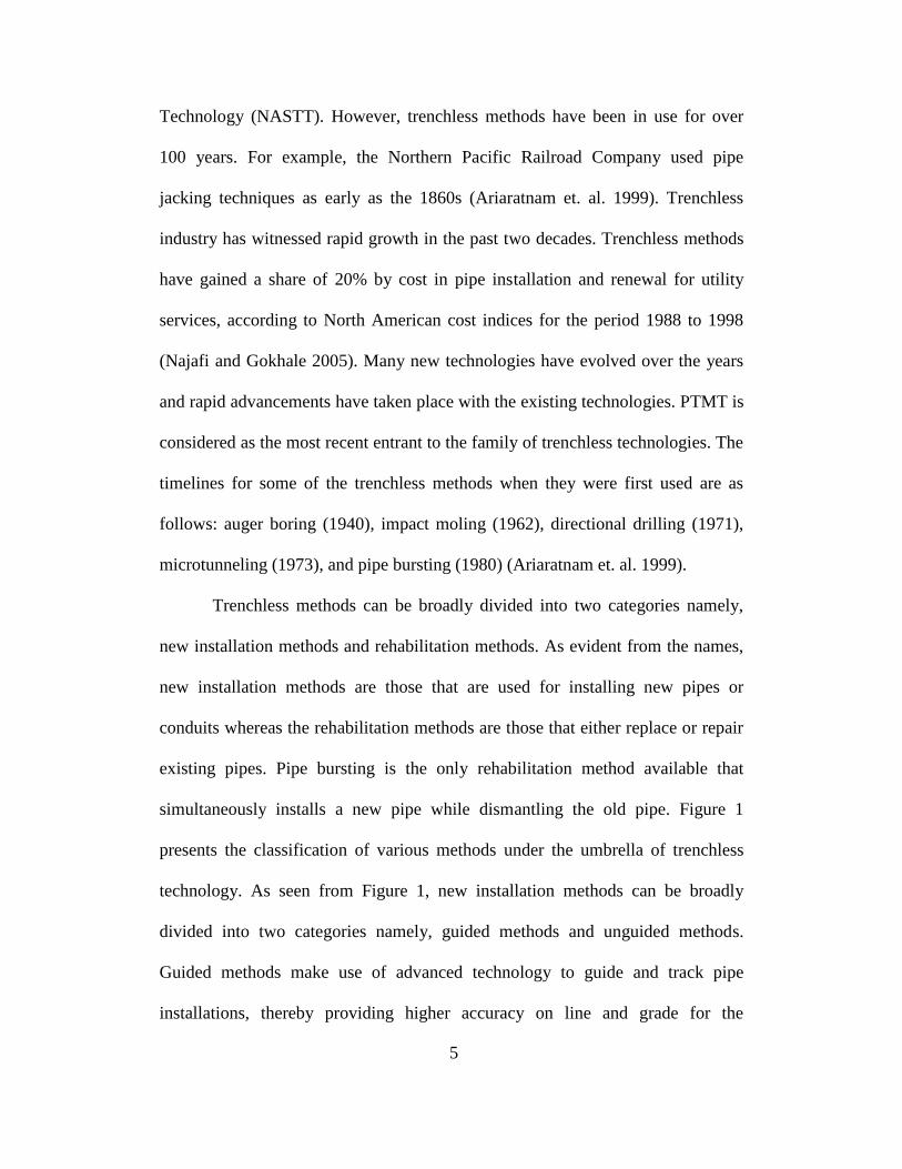
Trenchless methods can be broadly divided into two categories namely,
new installation methods and rehabilitation methods. As evident from the names,
new installation methods are those that are used for installing new pipes or
conduits whereas the rehabilitation methods are those that either replace or repair
existing pipes. Pipe bursting is the only rehabilitation method available that
simultaneously installs a new pipe while dismantling the old pipe. Figure 1
presents the classification of various methods under the umbrella of trenchless
technology. As seen from Figure 1, new installation methods can be broadly
divided into two categories namely, guided methods and unguided methods.
Guided methods make use of advanced technology to guide and track pipe
installations, thereby providing higher accuracy on line and grade for the
6
completed pipelines or conduits. Each of the trenchless methods is unique
pertaining to its purpose, applicability and capabilities. A comparison of the
capabilities of various new installation methods is presented in Table 1. Table 2
discusses the applicability of the various new installation methods in different
soils conditions. As seen from Table 1, PTMT and microtunneling are the most
accurate installation methods. Table 1 also shows that the drive lengths of PTMT
are somewhat limited compared to the other technologies. As seen from Table 2,
microtunneling is capable of working in a wide variety of soil conditions. Most of
the trenchless construction methods encounter limitations when tough ground
conditions such as, cobbles, boulders and rocks, are encountered.

7
FIGURE 1. Family of Trenchless Technologies (Adapted from ISTT 2011)
Trenchless Technology
New Installation Methods Rehabilitation Methods
Guided Methods Unguided Methods
Microtunn-
eling
Pilot Tube
Microtunneling
(PTMT)
Horizontal
Directional
Drilling (HDD)
Auger Boring Pipe Jacking Pipe Ramming
Pipe Bursting CIPP Lining Slip Lining Pipe Eating Close-Fit Lining

8
TABLE 1. Comparison of the Capabilities of Various Trenchless Methods (Najafi and Gokhale 2005, Abraham
et. al. 2002, Boschert 2006)
Parameter
Technology
PTMT HDD Auger Boring Microtunneling Pipe Jacking Pipe
Ramming
Diameter
4”-48”
(Typically up to
24”)
2”-54” 8”-60” 10”-10’ 42”-10’ 4”-60”
Drive Length Up to 500’
(Typically 300’) Up to 6000’ Up to 500’ Up to 1000’ Up to 1000’ Up to 200’
Pipe VCP, Concrete,
Steel, Fiberglass
HDPE, Steel,
PVC, Ductile
Iron
Steel, Ductile
Iron
PVC, Concrete,
FRP, clay,
conc.
RCP, Steel,
Fiberglass Steel
Accuracy .25” per 300’ +/- 2% of
depth of bore
+/- 1% of
length of bore Within 1”
Depends on
project
parameters
Depends on
project
parameters
Applications Sewer, Laterals
Water, Cable,
Sewer, Oil,
Gas
Casing Pipe Sewer Casing Pipe Casing Pipe

9
TABLE 2. Applicability of Various Trenchless Methods in Different Soil Conditions (Najafi and Gokhale 2005,
Abraham et. al. 2002, Boschert 2006)
Ground Conditions
Technology
PTMT HDD Auger
Boring
Microtunn-
eling
Pipe
Jacking
Pipe
Ramming
Soft to very soft clays, silts and organic
deposits Yes Yes Yes Yes
Not
Favourable Yes
Medium to very stiff clays and silts Yes Yes Yes Yes Yes Yes
Hard Clays and Highly Weathered Shales Yes Yes Yes Yes Yes Not
Favourable
Loose sands above watertable Yes (w/
lubricant) Yes
Not
Favourable Yes
Not
Favourable Yes
Medium to dense sand below water table Not
Favourable Yes No Yes No No
Medium to dense sands above water table Yes Yes Yes Yes Yes Yes
Gravels and Cobbles less than 2”-4” dia Yes Not
Favourable Yes Yes Yes Yes
Soils with significant cobbles, boulders,
larger than 4”-6” diameter
Not
Favourable
Not
Favourable
Not
Favourable
Not
Favourable
Not
Favourable Yes
Weathered rocks, marls, chalks, and
firmly cemented soils
Yes (w/ air
hammer) Yes Yes Yes
Not
Favourable
Not
Favourable
Slightly weathered to unweathered rocks Yes (w/ air
hammer)
Not
Favourable Yes Yes No
Not
Favourable

10
2.1.1 Trenchless Versus Open Trench
Trenchless technologies require significantly less trench work and surface
footprint compared to open trench and hence offer numerous advantages. In urban
settings, construction activities may lead to inconvenience and added costs to the
public, which are often characterized as “social costs”. Social costs are defined as
those that are neither direct nor indirect costs to the parties in a contractual
agreement (Allouche et. al. 2000). Savings in social costs is one the prime
advantages of trenchless technology over the traditional open trench method.
Government agencies and utility owners are beginning to realise the advantages
offered by trenchless technologies and favouring their selection over the open
trench method (Bruce 2002). This section presents a comparison between
trenchless technology and the traditional open trench in the five categories
including: 1) surface disruption; 2) safety; 3) damages to infrastructure; 4)
environmental issues; and 5) project costs.
Surface Disruption
Trenchless technologies offer numerous advantages over the open trench
method in this category. In urban settings, pipelines are commonly located
beneath the roadways. Advances in trenchless technology have facilitated
installations with minimum surface disruption and thereby minimizing the
disturbance caused to businesses, pedestrian and vehicular movement, and local
residents. When using open trench method, due to larger surface space
requirements the roads are narrowed down leading to traffic congestion. Detours
for roads are commonly required with trench work, which cause inconvenience,

11
loss of time, and added fuel costs. Businesses around the open trench construction
sites may lose revenues from loss of customers due to inconvenient access,
construction noise and clutter (McKim 1998). The costs arising out of the above
discussed issues are all part of social costs.
Safety
The accident rate for trench work is about 112% higher than that of
general construction (Everett and Frank 1996). Trenchless technologies requiring
significantly less trench work increase the safety factor for the crews. Also, there
is an increased probability for motor vehicle crashes in construction work zones.
For the year 2009, 2% of all motor vehicle crashes in the United States have
occurred in a construction or maintenance zone (NHTSA 2010). When using
trenchless technologies, the work zones occupy less area because of the lesser
trench work involved. Therefore, it can be asserted that installations using
trenchless technologies are much safer to both the crews and community when
compared to open trench method.
Damages to Infrastructure
As pipelines are often located beneath the roadways, employing open
trench method on such cases involves digging up the pavements followed by
restoration. It was observed that the life expectancy of pavements is reduced by
up to 60% with dig-up repairs (Najafi and Gokhale 2005). Since trenchless
methods require only minimal excavation, this issue could be largely avoided.
Compaction of back fill is a necessary process with open trench construction to
maintain ground stability. However, there may be long term affects and chances

12
of ground movement due to settlement. Also, the process of compaction may
affect existing utilities near the project. Settlement is relatively minimal with
trenchless methods when compared to open trench. However, there is a possibility
of ground disturbance when installing large diameter pipes using technologies like
auger boring.
Environmental Issues
Contaminated soils are frequently encountered when performing
excavations. These soils need to be properly disposed in compliance with the law.
The needs arising out of such activities may result in additional costs and loss of
productivity. The advantage offered by trenchless technologies in this respect is
that they require significantly lesser excavations and therefore the amount of
contaminated soils, if encountered, is relatively less in volume. During open
trench construction large amounts of soil is stockpiled on the site, before being
backfilled, possibly resulting in fine soil particles becoming airborne and
polluting air. Rain or water encountered during this process might result in soil
erosion and contaminated soils runoff into water bodies causing water pollution.
Trenchless methods, when compared to open trench construction, may
realize reduction in airborne pollutant emissions due to shorter project durations,
less use of construction equipment and less disruption to vehicular movement.
Additionally, projects executed using the open trench methods require
transporting considerable amounts of trench excavation, support and restoration
materials, resulting in greater emissions. Rehan and Knight (2007) determined
that it may be possible to achieve a 78 to 100% reduction in greenhouse gas

13
emissions by employing trenchless methods over open trench construction. In a
case study performed by Ariaratnam and Sihabuddin (2009), it was observed that
a project executed using open trench construction produced approximately 79%
higher emissions over a similar project completed using pipe bursting, a
trenchless rehabilitation method. It can therefore be concluded that trenchless
methods are more environment friendly.
Project Costs
Conventional open trench might be an expensive option compared to
trenchless technologies when installing at greater depths below the water table
(Neider 2006). When installing in such conditions with the open trench method,
dewatering solutions are necessary throughout the alignment which increase
projects costs. As seen from Table 2, there are many trenchless construction
methods that can perform in soils below the water table and may offer cost
advantages. In a research conducted by Zhao and Rajani (2002), it was observed
that microtunneling is much more expensive than open trench for all diameter
ranges. It was also seen than open trench is a cheaper option, compared to
microtunneling, HDD, and pipe jacking, in the large diameter range (38 inch to 72
inch). This may be due to the complexity involved in such projects. Even though
trenchless methods may appear to be a cheaper option because of less surface
disruption, few studies have verified this claim (Rayman et. al. 2008). It may be
concluded that costs are highly project specific and both open trench and
trenchless methods have their cost advantages depending on the project
conditions.

14
2.2 Introduction to Pilot Tube Microtunneling (PTMT)
Pilot Tube Microtunneling (PTMT), also referred to as pilot tube system
of microtunneling, guided auger boring and guided boring method, originated in
Japan and Europe two decades ago as a way to install 4 and 6 inch house
connections (Boschert 2007). Guided auger boring is defined as “Auger boring
systems which are similar to microtunneling, but with the guidance mechanism
actuator sited in the drive shaft (e.g. a hydraulic wrench which turns a steel casing
with a symmetric face at the cutting head). The term may also be applied to those
auger boring systems with rudimentary articulation of the casing near the head
activated by rods from the drive pit” (NASTT 2000). It was first introduced in the
United States in 1990s (Boyce and Camp 2008), and has since seen increase in
capabilities and popularity. PTMT was patented in the United States under the
name “Apparatus and Method for Pilot-Tube Guided Auger Boring” in 2001 by
David J. Monier and Francis E. Robinson, both from Perryville, Missouri (Monier
and Robinson 2001).
PTMT evolved from a combination of three other existing trenchless
technologies namely microtunneling, horizontal directional drilling (HDD) and
auger boring. The installation process of PTMT resembles that of HDD through
the use of pilot boring followed by reaming and product pipe installation. Both
PTMT and HDD use a slant faced steering head for directional control. PTMT
adopts its accurate guidance system from microtunneling, although in a slightly
different format. Further the technology is similar to auger boring in the use of a
jacking system and auger flights for spoils removal. Similarities between PTMT

15
and the three ancestral technologies are concurrently discussed in Section 2.3
while presenting the methodology. For information related to the methodologies
of the technologies ancestral to PTMT, refer to: HDD (Ariaratnam and Allouche
2000); Microtunneling (Powers et. al. 2007; Myers et. al. 1999); Auger Boring
(Iseley and Gokhale 1997).
The initial capabilities of the technology were in the range of 4 inch to 12
inch outside diameter pipes with single drive lengths up to 250 feet (Boschert
2007). The technology can now install pipes up to 48 inch outside diameter with
drive lengths in the range of 400 feet (Haslinger et. al. 2007). Pilot Tube
installations as long as 580 feet in a single drive has been completed successfully
as reported in Chapter 3. Accuracy in line and grade of 0.25 inch is possible on
installations up to 300 feet in length (Abbott 2005). Better optical guidance
systems and power hydraulics in the jacking frames have made larger diameters
and drive lengths possible.
The technology can perform in a variety of soils conditions though
cobbles and boulders might pose some difficulties. The technology can be
conveniently used in competent soils above the water table (Ramos and Stephl
2008). PTMT has been successfully used in weak soils with zero blow count. As
seen from Table 2, the technology’s performance is marginal when gravels and
cobbles of greater than 4 inch diameter are encountered. Recent developments
such as lubricants for loose sands, water control reaming heads for wet sands, and
air hammers for solid rock have increased the possibilities for different soil
conditions (Boschert 2007). The City of Atlanta completed drives of PTMT, as

16
part of its Combine Sewer Overflow Remediation Plan, in solid granite using a
combination of PTMT, air hammers and compressors (Bruce 2008).
The technology can install a variety of jacking pipe materials such as
concrete, clay, fiberglass, polymer concrete, and steel. Being a jacking
technology, PTMT favors the use of pipes that can withstand the high jacking
loads. Vitrified clay jacking pipe is predominantly used in PTMT installations for
the various advantages it offers such as high compressive strength, leak free
joints, long useful life, corrosion resistance, and affordability in the typical
product pipe section range of 3.3 feet to 6.6 feet (Bruce 2002). Fusible pipe has
also been successfully pulled back from the reception shaft behind both the pilot
as well as the temporary casings.
2.3 PTMT Methodology and Equipment
The three most common variants of PTMT are: 1) Two-Step Method; 2)
Three-Step Method; and 3) Modified Three-Step Method. There is little
difference in the site preparation and equipment setup among the three variants.
The first Part of this section details the site preparation phase of a typical PTMT
project. The next Part presents an in-depth discussion of the methodologies of the
variants of the technology along with presenting details of the equipment used.
2.3.1 Site Preparation and Set-Up
Site preparation for a drive of PTMT, begins by excavating jacking and
reception shafts. PTMT method requires jacking and receiving shafts for each
drive. As seen from Table 1, the typical drive lengths for PTMT are in the 300-
400 feet range. Since typical pipe installation projects are much longer, PTMT

17
projects are often executed in multiple drives. It is common for the receiving shaft
of one drive to act as a jacking shaft for another. If the project layout permits, two
drives can be performed from the same jacking shaft simply by rotating the
equipment and boring in the opposite direction. Since the jacking machines used
on PTMT installations are compact, the shafts are relatively small when compared
to microtunneling and pipe jacking. Shafts can either be rectangular or circular
depending on the project considerations. The jacking and reception shafts are
most commonly round, with the minimum size of jacking shafts being 8 feet in
diameter and reception shafts being 6.5 feet in diameter (Ramos and Stephl 2008).
The shafts are most commonly drilled by a vertical boring machine and a pre-built
corrugated metal structure is lowered to support the earth loads, as shown in
Figure 2.
FIGURE 2. Placing the Pre-Built Shaft Support (Boschert 2006)

18
When water is encountered during shaft construction or when it is
determined that the ground is unstable, concrete pads and thrust blocks are poured
at the bottom of the jacking shaft to withstand stresses from the heavy jacking
system and prevent any potential settling (Fisher 2003). After the construction of
the shaft is complete, the jacking machine is lowered into the jacking shaft and set
up rigidly. A guidance system is then set-up and the jacking frame is oriented to
match the desired line and grade using the digital theodolite of the guidance
system. With the site preparation and equipment set complete, the first step of
installing pilot tubes can begin.
2.3.2 Three-Step Method
Three-step method is the traditional form of PTMT. The method involves
boring a pilot hole, installing the auger casings and replacing the casings with the
product pipe.
First Step
First step, common to all the three variants of PTMT involves drilling a
pilot bore hole using a steering head trailed by pilot tubes. The process begins by
attaching a steering head to a pilot tube section and mounting the assembly on the
jacking frame. The operator adjusts the steering head and the jacking frame with
the assistance of the guidance system to match the desired line and grade. Initial
setup prior to drilling is very important as the accuracy of the final pipeline
depends on the accuracy of the pilot bore. Pilot boring is started by thrusting the
steering head into the ground. Once the steering head and the first pilot tube
section are inside the ground, thrusting is stopped and the jacking machine is

19
retracted to its original position. A new section of pilot tube is attached to the
trailing end of the pilot tube section already inside the ground. The pilot tubes are
fastened to each other using clips or their internal threading. The boring is
continued and the process of attaching new pilot tube sections is repeated until the
steering head reaches the reception shaft. The first step of the three-step method is
depicted in Figure 3.
FIGURE 3. First Step of the Three-Step PTMT Method
Torque and thrust are transferred to the steering head through the surface
of the pilot tube string. Steering head and the pilot tubes advance only by
thrusting and no rotation is used unless variations in the alignment are observed.
Pilot tubes advance by displacing and pushing the soil around them. Hence, no
soil is trapped inside them and the need for soil removal does not arise. Since the
diameter of the pilot tubes is very small, no significant ground movements are
observed during pilot boring. The pilot tubes, similar to the casings and product
pipe sections, are typically 3.3 feet or 6.6 feet in length (Boschert 2007). The

20
typical diameter of pilot tubes is 4.25 inch (Force et. al. 2005). Pilot tubes are
stacked at the site location in a manner depicted in Figure 4, and transferred into
the jacking shaft one after one as the pilot bore progresses.
FIGURE 4. Pilot Tubes Staged on the Site (Ramos 2009)
The guidance system used in PTMT is inspired from microtunneling.
While the guidance system used in microtunneling contains the light source in the
jacking shaft and the camera inside the boring machine, the places are reversed
for the guidance system used with PTMT where the light source is inside the
steering head and camera is in the jacking shaft. PTMT’s guidance system
comprises of a LED illuminated target, digital theodolite, camera and a monitor
screen. The LED target is mounted on the inside of the steering head. Prior to
pilot boring, a theodolite is setup in the jacking shaft at an orientation that exactly
matches the expected line and grade of the product pipe.

21
A camera is mounted on top of the theodolite and focused on the centre of
the target. The LEDs on the target form two concentric circles and a radial
straight line, as seen from Figure 5. While the circles are helpful in identifying the
variations in line and grade of the steering head, the straight line is used to
identify the orientation of the slant face of the head. The hollow passage of the
pilot tube string serves as an optical path for the guidance system. One of the
factors affecting the length of the drive is the visibility through the pilot tube
string. Visibility through the pilot tube stem could be affected due to condensation
within the pilot tube cavity. This problem could be easily overcome by using a
dry inert gas (Boyce and Camp 2008).
FIGURE 5. LED Illuminated Target Mounted Inside the Steering Head (Boschert
2006)

22
The operator continuously monitors the position (with respect to the line
and grade axes) and orientation of the steering head from the camera output
displayed on the monitor. This guidance system of continuous monitoring is
necessary to install pipe precisely on line and grade. The guidance system with its
various components is displayed in Figure 6.
FIGURE 6. Guidance System with its Components (ISTT 2011)
The slant faced steering head used in PTMT is inspired from HDD. The
slant face is an important feature of the steering head as it is helpful in correcting
variations in the alignment. If any variations in the line and grade are observed,
thrusting is stopped. The steering head is then rotated to a necessary clock
position and the pilot stem is pushed back to alignment.

23
Several different types of steering heads with different slant angles are
available. The supporting equipment for the steering heads include: a connecting
adapter, an adapter to allow fluid and air flows when using dual walled pilot
tubes, and a target holder. Different types of steering heads along with the
supporting equipment are displayed in Figure 7.
FIGURE 7. Various Types of Steering Heads and the Supporting Equipment
(Akkerman 2010)
The pilot tubes could either be single or dual walled. Dual walled tubes are
used to pump lubricant to the steering head through the cavity between the two
walls. Lubrication reduces the friction between the steering head and the soil
making greater drive lengths possible. In case of dual walled pilot tubes, the thrust
is transmitted to the steering head through the outer walls, while the inner walls
are used for transferring torque.
The jacking machines used for PTMT are similar to the ones that are used
for auger boring. Jacking machines are also known as Guided Boring Machines
(GBMs). The jacking machine determines the jacking force/horizontal pressure,

24
rotational torque and penetration rate of the boring process on a project. Since
PTMT method is primarily used on installations of small diameter pipes, the
required jacking forces are not as high when compared to microtunneling. Hence
jacking machines with significantly lower capacity are used on PTMT method.
Therefore the jacking machines, as shown in Figure 8, are very compact (Monier
and Vedder 2000). A single jacking machine is capable of performing all the
three-steps on a typical PTMT method – drilling pilot tubes, jacking auger casings
and jacking final product pipe.
FIGURE 8. Jacking Frame (Akkerman 2010)
The selection of a jacking machine is governed by the following
considerations: length of bore, diameter of the final pipe and expected resistance
from the ground. Jacking machines use a hydraulic motor as a source for thrust.
These motors are powered by external power units called power packs that are

25
stationed on the surface above the jacking shaft. Jacking machines are equipped
with hydraulic pressure gauges to monitor the thrust and rotation pressures at any
given time. Any changes in the soil conditions, as the pipe installation is in
progress, could easily be identified using these gauges. Akkerman, Bohrtec and
Wirth are the major manufacturers of jacking machines and other ancillary
equipment. Akkerman manufactures jacking machines (GBMs) especially for the
PTMT method. Akkerman’s guided boring machines are capable of installing 4-
48” outside diameter pipes in displaceable soils under 50 blow count (Akkerman
2010).
Pilot bore is complete after the steering head reaches the reception shaft
where it is retrieved. The guidance system may now be removed as it is no longer
required. At this point of the installation, a survey can be performed on the pilot
tube at the reception shaft to verify line and grade accuracy of the initial survey
and setup. If a survey or setup error is found, the pilot tubes can be retracted and
reinstalled before proceeding to the second step of the installation.
Second Step
The second step in the three-step PTMT method, as shown in Figure 9,
involves reaming the pilot hole to a diameter slightly larger than that of the final
pipe, while simultaneously installing auger casings. The purpose of this step is to
increase the diameter of the pilot bore. The second step begins by attaching the
rear end of a reaming head or a cutter head to an auger casing, as shown in Figure
10. This assembly is then fixed on the jacking frame. The front end of the reamer
is attached to the last section of the pilot tube inside the ground using a special

26
adapter. The auger, coupled inside the first casing, is fastened to the drive swivel
in the jacking frame. The reamer is advanced by a combination of thrust and
torque. Thrust force and torque are transferred to the face of the reaming head
through the surface of the augers. After the reamer and the first auger casing are
totally inside the ground, the jacking frame is retracted back to its original
position. A new casing is lowered into the jacking shaft and attached to the
jacking frame on one end and the other end is attached to the casing which is
already inside the ground. The auger inside the new casing is attached to the
previous auger on one end and the other end is attached to the drive swivel on the
jacking machine. The boring is continued and the process is repeated until the
casings replace all the pilot tubes.
FIGURE 9. Second Step of the Three-Step Method
Augers are rotated to transport the excavated soil back to the driving shaft.
The outer diameter of the rear end of the reamer is slightly larger than that of the
auger casings. This feature creates an “overcut” to reduce the friction between the
casings and the soil. Overcut eases the ground resistance on the auger casings,

27
thereby lowering the jacking forces. Typically, a 1.25 inch overcut is
recommended (Ramos 2009).
FIGURE 10. Reaming Head Welded on the Auger Casing
(Anderson 2008)
The pilot tubes are retrieved at the reception shaft as the casings are
advanced. The augers that are connected to each other, forming an auger string
continuously transport the excavated soils back to the jacking shaft. However,
once the installation of casings is complete soils can be transported to the
reception shaft by rotating the augers in the opposite direction. Spoils are
removed from the jacking shaft by using either a muck bucket or a vacuum truck
(Sewing et. al. 2009). A lubricant may be used to reduce friction between the
casings and the soil. Lubricant can either be applied before each casing is
dispatched for drilling or continuously using pipes that travel along the inside or
the outside of the top of the casings.

28
Auger casings used with PTMT are typically 3.3 or 6.6 feet long and are
made from steel (Monier and Vedder 2000). Auger casings are available in a
variety of diameter sizes. Steel is the material of choice for the auger casings, as
the casings should be able to withstand the potential damage caused by augers
that rotate inside them and also withstand the high jacking forces that are required
to cut through the soil. Auger casings are stacked on the site, as shown in Figure
11, and transferred to the jacking shaft one after one as the second step is in
progress.
FIGURE 11. Auger Casings with Augers (Wallbom and Huber 2008)
As PTMT method is primarily used on installations of small diameter
pipe, not all product pipe materials might be able to withstand the high jacking
forces required to cut through the soil. Hence the use of auger boring technique,
inspired from the auger boring method, provides a flexibility of using a variety of
pipe materials for the final pipeline as the soil would have already been excavated

29
by the final stage of installation and thereby needing jacking forces just enough to
push out the casings.
Third Step
The third step, as depicted in Figure 12, involves replacing the previously
installed auger casings with the product pipe. The lead end of first pipe section is
attached to the rear end of the last casing using a special adapter. Pipe sections
replace the auger casings in a similar fashion as the auger casings replace pilot
tubes in the second step. However, there is no excavation involved in the third
step of the three-step method as the product pipe is either equal or smaller in
diameter than the auger casings. The auger casings are retreived from the
reception shaft as the pipe sections are advanced. Only those pipe materials that
can withstand high jacking forces could be used in this step.
FIGURE 12. Third Step of the Three-Step Method

30
2.3.3 Two-Step Method
The first step of the two-step method is the same as that of the three-step
method. The second step in this method combines the second and third steps from
the three-step method. Hence the discussion in this Part is only focused on the
second step of two-step method. In the second step, sections of product pipe are
simultaneously installed as the reamer advances through the ground replacing the
pilot tubes installed in the first step. Step 2 of the two-step method is depicted in
Figure 13.
FIGURE 13. Second Step of the Two-Step Method
The second step begins by mounting a reaming head and a product pipe
section assembly on the jacking frame. Each product pipe section contains an
auger casing, coupled with augers on the inside of the casing, as shown in Figure
14. A special reaming head, different from the ones used with the three-step
method, is used to funnel the excavations into the auger casing. After the reaming
head and the first section of the product pipe are completely pushed into the
ground, the jacks are retracted back to their original position. A new section of

31
product pipe, coupled with auger casings on the inside, is then lowered into the
shaft and set up on the jacking frame. The new pipe section is connected to the
trailing end of the pipe section already inside the ground. Two additional sets of
connections, for the auger casing and the auger, also need to be made for this new
section. The process is repeated until the pipe sections replace all the pilot tubes.
After the product pipes are installed, auger casings are retrieved either from the
jacking shaft or the reception shaft.
FIGURE 14. Auger Casings Inside the Product Pipe Sections
The prime advantage of using this method over the three-step method is
that the contractors are able install multiple pipe diameters using the same set of
auger casings. However, as the diameter of the product pipe increases, it may be
difficult for the smaller auger casings to transport large quantities of excavated
material (Sewing et. al. 2009).

32
2.3.4 Modified Three-Step Method
The modified three-step method makes use of a powered cutter head
(PCH) or a powered reaming head (PRH). This variant is the newest addition to
pilot tube methods (Boschert 2007). The first two-steps for this method are the
same as that of the three-step method. Therefore the discussion presented in this
Part only focuses on the third step of the modified three-step method.
The third step for this method is similar to that of the three-step method,
except that this method uses a PCH or PRH as a lead end of the product pipe
section chain, when replacing the auger casings. A powered head is used to
increase the diameter of the bore hole further to match that of the larger product
pipe. After the second step is complete, a PCH or PRH is lowered into the jacking
shaft and set up on the jacking frame. The powered head is then attached to the
rear end of the last auger casing already inside the ground. Further the powered
head is also attached to the auger chain inside the installed casings. The powered
head is advanced by the product pipe while it cuts around the auger casings. The
newly excavated soil by the powered head is transported to the reception shaft
through the previously installed auger casings from the second step. The powered
head reverses the rotational direction of the augers for this purpose. The third step
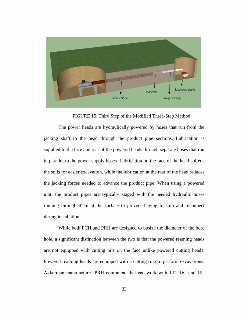
is depicted in Figure 15.
33
FIGURE 15. Third Step of the Modified Three-Step Method
The power heads are hydraulically powered by hoses that run from the
jacking shaft to the head through the product pipe sections. Lubrication is
supplied to the face and rear of the powered heads through separate hoses that run
in parallel to the power supply hoses. Lubrication on the face of the head softens
the soils for easier excavation, while the lubrication at the rear of the head reduces
the jacking forces needed to advance the product pipe. When using a powered
unit, the product pipes are typically staged with the needed hydraulic hoses
running through them at the surface to prevent having to stop and reconnect
during installation.
While both PCH and PRH are designed to upsize the diameter of the bore
hole, a significant distinction between the two is that the powered reaming heads
are not equipped with cutting bits on the face unlike powered cutting heads.
Powered reaming heads are equipped with a cutting ring to perform excavations.
Akkerman manufactures PRH equipment that can work with 14”, 16” and 18”

34
outer diameter pipes. The PCH equipment range for Akkerman products is 20” to
44” outer diameter. Increaser kits are also available from Akkerman that increase
the PCH range to 48” (Akkerman 2010). PCH and PRH heads are depicted in
Figures 16 and 17 respectively.
FIGURE 16. Powered Cutting Head (PCH) (Akkerman 2010)
FIGURE 17. Powered Reaming Head (PRH) (Akkerman 2010)

35
2.3.5 Hybrid Methods
While PTMT is designed as a standalone pipe installation system, the
technology is often used in conjunction with other trenchless technologies. The
three main hybrid versions of PTMT are, PTMT-Auger Boring, PTMT-HDD and
PTMT-Pipe Ramming. The idea behind such hybrid methods is to establish an
accurate alignment using PTMT’s guided pilot boring followed by product pipe
installations by the other technology.
PTMT-Auger Boring
The first step in the PTMT-Auger Boring hybrid method is guided
installation of pilot tubes similar to conventional PTMT. The PTMT machine is
attached to the auger boring rails at the outset using special adapters. Once the
first step is complete, the PTMT machine is removed from the jacking shaft and
replaced with a auger boring machine. A reaming head is attached to the last
section of the pilot tube assembly. Now that the line and grade of the installation
are established, the auger boring machine tunnels the augers into place while the
pilot tubes are retrieved from the reception shaft. Typically auger boring
installations could be realized at an accuracy of +1% of the length of the bore
(Najafi 2004). The low level of accuracy makes installing larger diameter pipes at
longer drive lengths impractical, especially in congested urban settings with
narrow tolerances. The poorer accuracy levels also pose grade problems. To
counter this, the conventional practice has been to tunnel larger casings and then
install product pipes within the casings at the required grades. Due to precise

36
installations through this hybrid method, the contractors can use smaller casings
and hence save on the casing costs (Anderson 2008).
PTMT-HDD
Plastic pipes such as PVC and HDPE could not be used with conventional
PTMT because of their low compressive strengths. However, due to their high
tensile strengths they are extensively used with HDD that pulls the product pipe
into place. The need for installing such pipe materials accurately on line and grade
has led to the development of PTMT-HDD hybrid method. The first step of this
hybrid method is the same as that of the conventional PTMT method. Once the
pilot bore has been completed, the PTMT machine is removed from the jacking
shaft and replaced with a HDD drill rig. The drill rods of the HDD rig push the
pilot tubes into the reception shaft where they are removed. Once the drill rods
reach the reception shaft, a reamer head trailed by a pre-welded chain of HDPE
pipes is attached to the first section of the drill chain. The HDD rigs then pulls the
HDPE pipe chain into the pilot tube tunnel. This hybrid method is typically used
with water pipelines.
PTMT-Pipe Ramming
The PTMT-Pipe Ramming hybrid method is used to add the guided
tunneling component to the otherwise relatively inaccurate pipe ramming
technology. The first step in this method is the same as that of the conventional
PTMT method. A PTMT machine is attached to the pipe ramming rails using a
special set of adapters. After the pilot tube boring is completed successfully, the
PTMT machine is removed from the jacking shaft and replaced by a pipe

37
ramming machine. A reamer, trailed by casing pipe, is attached to the last section
of the pilot tube. Steel casings are tunneled into place by the pipe ramming
equipment while the pilot tubes are retrieved from the reception shaft. After the
steel casings replace all the pilot tubes, augers remove spoils collected inside the
casings.
2.4 Advantages and Limitations of PTMT
PTMT is best suited in congested urban settings, where applicable,
compared to open trench method and other similar trenchless methods such as
microtunneling and auger boring. The guided boring machines used for PTMT are
compact, compared to other trenchless technologies, thereby requiring smaller
surface lay down areas and smaller shafts. This minimizes the social costs and
disturbance to vehicular and pedestrian movement. Also PTMT is inexpensive
and less technology intensive when compared to microtunneling (Abbott 2005).
PTMT can perform well in soils below the water well, though it has some
limitation when dense sands are encountered. As previously discussed, using open
trench method in such conditions may be expensive. PTMT can also be used for
exploratory work before casings or product pipes are installed. Abandoning pilot
tubes inside the ground is a cheaper option when compared to loss of productivity,
time and loss of expensive casings or product pipe upon a drive of main
installations being abandoned due to unforeseen circumstances (Anderson 2008).
Today’s urban underground environments are congested and often require
new pipe installations within close tolerances to existing infrastructure.
Considering the high levels of grade and line accuracy associated with PTMT, it

38
is possible to install pipes with close clearances to existing utilities. As an
example, PTMT method was successfully used to install a waterline within 3 feet
of a gas line on a project in Alaska (Ramos and Stephl 2008). Another advantage
of PTMT is that the technology offers the same level of accuracy as
microtunneling at significantly lesser costs (Haslinger et. al. 2007). However,
PTMT is not very effective compared to microtunneling, when installing in
cobbles.
Even a slight condensation in the optical path (pilot tube cavity) may
result in problems to the guidance system. Setting up and flushing the pilot tube
cavity using a dry inert gas might delay production and add to the cost of
installation. Further, the technology as it is can only be used in select soil
conditions as seen from Table 2. Additional equipment such as air hammers are
required when installing in tough grounds like rocks, marls and chalks. PTMT,
like auger boring, being an open-face tunnel technology may require additional
efforts to control flowing ground when installing below the ground water level
(Gelinas et. al. 2010).
2.5 Case Studies
This section presents three case studies of different projects on which
PTMT methods were used. The following case studies highlight projects’
successes with PTMT, advantages of the technology, importance of geotechnical
information and the use of various method of PTMT, among other subjects.

39
2.5.1 City of Bloomington Project (Force et. al. 2005)
This case study demonstrates the reasons for the selection of Pilot tube
microtunneling (PTMT) over open trench method and other trenchless
technologies. The case study also highlights the importance of proper
geotechnical investigation when using trenchless technologies in general and
PTMT in particular. The project under discussion is owned by “The City of
Bloomington”, Minnesota. This is a sewer construction project around the Mall of
America, to allow for large scale commercial expansion around the mall. The
selected layout for the sewer required the installation of 2,074 feet of 18 inch clay
sanitary sewer pipe, 150 feet of 36 inch steel casing, 168 feet of 18 inch restrained
joint DIP sanitary sewer pipe, and seven new manholes.
There were many factors controlling the choice and the method of
construction such as significant construction activity was to take place during the
Christmas holiday season of 2003, but the infrastructure above the proposed
pipeline was very congested and disruption to the businesses and public was not
desired by the city. Other factors that dictated the selection of an appropriate
construction method were unfavorable Minnesota’s weather conditions in the
winter, limited right of ways, close proximity to existing utilities and geology.
The geotechnical report identified the existence of a high water table as a primary
risk. The geotechnical evaluation also identified poorly graded sand commonly at
many test bore holes along the layout of the proposed sewer.
Open trench construction was ruled out considering the space limitations,
potential disruption to businesses and prevailing geotechnical conditions. The

40
engineers initially proposed microtunneling or an approved alternate trenchless
method for the construction. The limited right of ways demanded the reception
and jacking shafts to be as small as possible. The contractor proposed PTMT as
the alternate method and finally the owner issued an addendum authorizing
microtunneling and PTMT as the only acceptable methods for construction.
PTMT was selected primarily for the small sizes of shafts required and accuracy
offered by the technology in terms of line and grade allowing installations at close
tolerances to existing utilities. Also, the technology’s capability of performing
well under groundwater conditions, with the exception of dense sands, favored its
selection. While microtunneling is a capable method in the investigated
geotechnical conditions, it was not selected considering the high costs associated
with the technology and large surface footprint requirements. The project was
awarded to ECI Inc. The contractor used the two-step PTMT method for the
installation. The construction began on October 20, 2003 and was complete on
April 8, 2004. A total of 10 round shafts were dug. The jacking shafts measured 8
foot in diameter, while the receiving shafts placed had a diameter of 6 foot.
The project encountered many unforeseen geotechnical conditions during
the course of construction. The geotechnical reports provided by the designer and
the owner at the beginning stages of the project were later discovered to be
incomplete and inaccurate. While the geotechnical report made no mention of the
presence of cobbles along the layout, they were frequently encountered forcing
the installation to be stopped midway on several occasions. Remedy methods such
as replacing the reaming head with a cutting head also proved futile as the auger

41
casings were clogged with cobbles of large sizes. In one of the drives, the drill
encountered cobbles which built up in front of the reaming head preventing the
augers from transporting excavated material back to the reception shaft. This
resulted in an increased mass build up in front of the reaming head and thereby
significantly increasing the required jacking forces. The drive had to be stopped
when the required jacking pressure reached the capacity of the jacking frame of
100 tons.
The tooling trapped inside the earth from stopped drives could not be
excavated until the holiday season was over, thereby forcing the contractor to
uncouple the jacking frames from the failed drives and work on the new drives.
This put significant strain on the contractor to source new tooling and expedite the
work progress to meet deadlines. Microtunneling or other trenchless methods that
can efficiently handle installation in cobbles could not be used when PTMT
failed, because the sizes of the compact shafts that were already in place would
not fit their requirements. Though the project completed nearly on the anticipated
time, the project budget doubled. Therefore it is imperative to have good
geotechnical information before a suitable trenchless technology is selected or
work is commenced. Especially when using PTMT, a proper investigation should
be made over the sizes of cobbles possibly encountered.
The project encountered a problem with the optical guidance system
initially. This was due to the condensation of air inside the pilot tubes which
caused sight problems in the optical cavity. The crew used extra dry nitrogen to
flush out the pilot tubes and it worked well. Installation on one of the drives was
42
halted for a brief while when the temperature reached minus 30 degree
Fahrenheit. The benotine lubrication system and the hydraulics froze at this
temperature. The project also faced some issues with faulty equipment resulting in
installation delays.
The many unforeseen conditions encountered, resulted in extra costs and
burden on the contractor. The jacking system chosen based on inaccurate
geotechnical investigation, could not perform in the unanticipated ground
conditions. The owner recognized the change of geologic conditions and
processed change order to that effect. This case study highlights the importance of
thorough and comprehensive geotechnical investigation, for the proper selection
of the methods and equipment, and also to the overall potential success of the
project.
2.5.2 Two Projects using PTMT-HDD Hybrid Methods (Ramos 2009)
This case study demonstrates the methodologies of two projects that used
PTMT in conjunction with HDD for the installation of water pipelines. This
hybrid method is capable of installing water pipelines, at high accuracy in line and
grade, using plastic pipes which are otherwise impossible to install using
traditional PTMT. The hybrid method involves drilling a pilot bore, precisely on
line and grade, using a PTMT machine as the first step. Once the pilot bore is
complete, the product pipe is installed along the centerline of the pilot bore using
the reaming and pull-back processes similar to HDD. The contractor on both the
projects was Trenchless Construction Services based in Arlington, Washington.
Lessons learned from one project were used for the success of the other project.

43
The first project based in Washington state involved installation of 1000
feet of 10 inch HDPE gravity sewer. The project was initially started as open
trench, however trenchless methods were sought for the final stretch as it was
proving very difficult to install via open trench in the dry running sands. The
contractor proposed to use a hybrid of PTMT and HDD methods for this project
as well. As a first step, the pilot tube unit was placed in a 10 foot by 20 foot
jacking shaft and boring was begun. Pilot bore drives varied from 300 to 350 feet.
Once the pilot bore was complete, the PTMT machine was removed from the
jacking shaft and replaced with a HDD rig. The HDD drill rods then pushed out
the pilot tubes into the reception shaft. Once the drill rods reached the reception
shaft, a steering head was attached to the drill rods and a curve bore was drilled to
the surface. A 14 inch reamer was attached to the drill rods after it broke at the
surface. The other end of the reamer was attached to a swivel that was trailed by a
pulling head.
A continuous HDPE pipe was pre-welded to the pulling head and the pull
back operation was started. Drilling mud was used during the reaming and
pullback operation to remove spoils. The installation of one drive was complete
when the HDPE pipe was pulled back from the reception shaft to the jacking
shaft. After completion of a drive, the HDD drill rig was replaced with the PTMT
machine to complete a drive in the opposite direction. After pilot boring on the
second drive was complete, the PTMT machine in the jacking shaft was again
replaced with the HDD drill to perform the pull back operation. This operation
44
cycle was tedious as the respective equipment for PTMT and HDD had to be
replaced each time.
The second project, located in Alaska, involved installation of over 1100
feet of 8 inch water line in a severely congested underground environment. Due to
the high accuracy offered by PTMT in line and grade, the designer therefore
recommended the technology which was later modified by the contractor. The
contractor proposed a hybrid of PTMT and HDD, primarily because this method
would be able to install HDPE pipe. HDPE pipes, mostly used for the water line
possess low compressive strengths thereby eliminating their use with jacking
technologies such as PTMT. The pipe was to be installed beneath a narrow drive
way at a depth of 10 to 11 feet in gravely soils and the main right of way for
homes in that area had four below-grade utilities. Because of the congested
environment, both above and below the ground, and also due to utility and service
lines observed, trenchless methods were sought over open trench construction.
PTMT was selected over its peers largely because of the congested construction
environment which demanded installations at high precision. HDD was originally
considered to replace the existing water line but the existing soil conditions
rendered HDD method as non-feasible.
The lessons learned in the Washington project were incorporated in the
Alaska project especially into the equipment setup and layout. For example, the
Washington project revealed that initiating the bend from the reception pit to the
surface may result in a long distance from the pit to the surface. Also it was
learned that placing the drill rig inside the jacking shaft was not advisable as all
45
the ancillary equipment would have to run down to the rig from the surface. The
Alaska project, instead, placed the HDD rig near the reception shaft. A sloped
path from the rig to the reception shaft was open trench by the contractor as the
depth of the installation was only 10 feet. Once the first step of pilot boring was
complete, the drill rods pushed the pilot tubes back into the jacking shaft. Pull
back operation was performed from the jacking shaft to the reception shaft. One
drive was complete when HDPE pipe was installed on the particular section. After
completion of a drive, the PTMT machine was turned inside the jacking shaft to
initiate pilot boring in the opposite direction for the next drive. PTMT machine
had to be moved only once for two drives, while the HDD rig positioned on the
surface could be easily moved after each drive. This work structure heavily
reduced the set up times for each drive.
The two projects demonstrated the various advantages of using the PTMT-
HDD hybrid method. HDPE pipe that can otherwise not be installed with PTMT
could be installed using this method at high precision. PTMT, when compared to
HDD, is a time taking method in having to push the casings and then replace the
casings with product pipe sections. This hybrid method extracts the best from
both the technologies: expanded pipe options, faster installation, high line and
grade control. The case study demonstrated an efficient work layout for using this
hybrid method.
2.5.3 St. Louis Project (Sewing et. al. 2009)
This case study addresses the following areas: selection of PTMT over
other trenchless technologies, the use of powered heads for installing large

46
diameter pipes in tough soil conditions, the importance of geotechnical
investigation. The current PTMT project for the Metropolitan St. Louis Sewer
District (MSD) required installation of approximately 1,900 feet of 18-inch and
45 feet of 8 inch gravity sanitary sewer up to a depth of 23 feet. The proposed
pipeline was located under the parking lot of a major mall and crossed a busy
street. There were many utilities that ran in close tolerances to the proposed
alignment. Trenchless methods were chosen over open trench construction
primarily to minimize the interruption caused to traffic flow, to provide safe work
zones around the mall, and to not disturb the utilities that service the mall. PTMT
was chosen over its peer trenchless methods as the jacking and reception shafts
required by PTMT are much smaller compared to the other methods. Also, lesser
on-surface space requirements and suitability for the pipe diameter to be installed
favored the selection of PTMT.
The 8 inch diameter pipe was installed using the conventional three-step
PTMT method. The 18 inch diameter pipe was installed using the modified three-
step method where a powered cutting head (PCH) was used. This method was
selected as the geotechnical evaluation indicated the presence of large diameter
gravels, hard clays and shales. The final pipeline was installed at an accuracy of
3/8th
inch or better in line and grade. Extreme care was taken during the design
phases to align the pipeline so as to avoid existing underground utilities,
underground structures and unsuitable soil conditions. Aerials and contour
drawings from over 40 years were studied in this process. A through geotechnical
investigation was performed to determine the characteristics of the soils. A total

47
of 17 borings were drilled along the alignment of the proposed pipeline and soil
samples were collected at various depths. The soil samples encountered were
mostly silty clay or clay mixed with gravel.
Both the diameter installations used standard pilot tubes and 11 inch
outside diameter auger casings for the first and second steps, as in a conventional
three-step PTMT method. For the 8 inch diameter pipe, the crew used the
conventional three-step method of replacing the casings with the product pipe.
However, for the 18 inch diameter pipe installation a PCH was used to cut
through the ground followed by the product pipe installation. PCH reamed the
bore hole further to match the outside diameter of the product pipe. This project
had been successfully executed with the use of PCH, which would have been
otherwise very difficult to install in the tough soil conditions.
The final cost on this project slightly exceeded the initial estimate. The
cost increase was due to the presence of gravels and cobbles for over 50% of the
total project length of the 18 inch diameter pipe. Three concrete piers were
encountered during the final drive, which required the need of excavation and
removal. This was a significant part of the extra cost. The presence of gravels and
cobbles slowed down the installation greatly. The project suggested that
contractors must consider the geotechnical conditions adherently and bid their
PTMT project accordingly. PTMT avoided inconvenience to the traffic flow
because of its smaller on-ground space requirement and smaller shafts. This case
study demonstrates the successful use of PCH in tough soil conditions. Even

48
though a through subsurface investigation was performed it fell short in
identifying some underground structure which resulted in added costs and delays.
49
CHAPTER 3
SURVEY
The first section of this chapter discusses the techniques used in
development, and organization of the survey questionnaire. The next section
discusses the results of the compiled data of the survey responses.
3.1 Survey Methodology
A survey of the pilot tube microtunneling (PTMT) industry in North
America was developed at Arizona State University, in consultation with
equipment manufacturers, industry consultants and contractors working with the
technology. Though the technology’s methods, applications, capabilities and
limitations are well documented, there is little documented literature available on
the industry trends, business practices and contractors’ perspectives on the
technology. The survey was aimed at studying these topics along with the
technology’s applications and capabilities.
To ensure a higher response rate, the survey was designed to be short.
Most of the questions in the survey were designed in a format such that the
respondents can readily answer them without having to browse through project
records. For example, some questions in the survey asked for approximate
percentage distributions (eg: client types, contractor roles). Yet the survey
extracted critical data such as the number of PTMT projects completed by the
contractors, amongst other trenchless technologies, between 2006 and 2010. This
information was critical in generating industry trends, as it was used to calculate
weighted averages from the contractor’s responses to some other questions.
50
The questions in the survey were organized under three sections. The first
section contained questions related to the contractor’s business activities and
experience with PTMT among other trenchless technologies. In the second
section contractors were asked to provide information on work
solicitation/contractual practices, types of project undertaken and their experience
with different pipe materials, diameters. The final section addressed project
planning, risk considerations and the use of different variants of the technology.
The survey is included in Appendix A.
A list of PTMT contractors was put together in consultation with major
equipment manufacturers and industry consultants. The Del E. Webb School of
Construction at Arizona State University started contacting contractors through
phone calls, email and mail starting in September 2010. Approximately 110
contractors were contacted. In correspondence with the contractors it was
determined that approximately 85 of the 110 contractors actively work with the
technology. As on February 2011, 22 questionnaires were returned representing a
response rate of approximately 26%. The response rate for this study is
comparable to the response rate of 31% for a similar survey conducted by
Allouche et. al. (2000) for the Horizontal Directional Drilling (HDD) industry.
The responses were diverse in terms of company size, geographic location,
geological conditions and experience with PTMT. It was observed that a majority
of PTMT contractors also pursued other trenchless technologies. A total of 20
responses were obtained from contractors in the United States, and 2 were from
Canada. Questions 4 and 5 from Part 2 of the survey, that were aimed at

51
extracting data related to the contractors’ experience with different pipe materials,
were left out from the analysis as they failed to gather enough responses. This is
mostly probably due to the effort needed in answering them. Barring these two
questions, the rest of the questions could be readily answered and the response
rate was expectedly very high.
The individual survey responses are kept in strict confidence and the same
was communicated to the contractors. This study makes use of only compiled
information with no individual data being attached with any respondent. A list of
the contractors that participated in this study is presented in Appendix B.
3.2 Results
The results presented in this Chapter are based on survey responses from
22 contractors, henceforth referred to as the contractors, working with pilot tube
microtunneling among other trenchless technologies. The respondents have a
combined experience of 450 pilot tube microtunneling (PTMT) projects among a
total of 5,770 trenchless projects completed between 2006 and 2010. The data
provided by the respondents was cohesive with the general trends in the
Trenchless industry. The respondents were asked to provide data in the form of
percentages for some questions, for example the client types such as private
clients, city, state and federal governments. These percentages were then
multiplied with their individual number of PTMT projects to calculate weighted
averages.
The number of projects completed during the surveyed period, 2006 to
2010, varied considerably from contractor to contractor. Therefore it is likely that

52
the analysis for some of the survey aspects, that considered the number of projects
to extract trends, could be favorably inclined towards the results provided by the
bigger contractors. Therefore, where necessary, the data was also analyzed by
considering the number of respondents responding in favor of a particular trend in
addition to the analysis based on the total number of projects towards the trend.
As previously noted questions 4 and 5 from Part 2 of the survey (see Appendix A)
were not considered for analysis as most of the survey responses did not provide
quantifiable data for these questions.
3.2.1 Company Profile
This section presents analysis of the information provided by the
respondents in Part 1 of the survey questionnaire titled company profile. Part 1 of
the questionnaire aimed at gathering general company data regarding the areas of
activity, experience with PTMT, breakdown of the number of projects completed
using various trenchless technologies between 2006 and 2010, their role on the
projects, client types and ownership of equipment.
Areas of Activity
Surveys responses were obtained from across United States and Canada.
Of the 22 surveys that were returned, 20 were from the United States and two
were from Canada. A map of the North American continent showing the areas of
activity of the respondents is presented as Figure 18. A state or province was
identified as an area of activity if the responding contractor had completed a
PTMT project in that location. The respondents together had worked in 28 of the
50 US States, and in three Canadian provinces. There was also one contractor
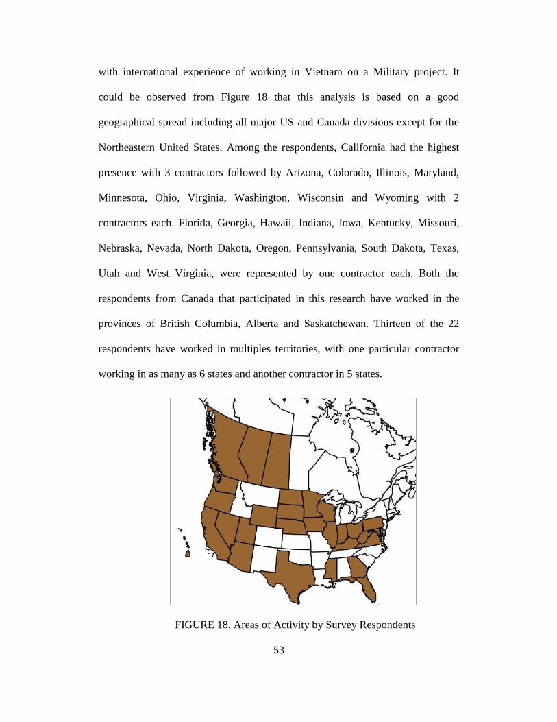
53
with international experience of working in Vietnam on a Military project. It
could be observed from Figure 18 that this analysis is based on a good
geographical spread including all major US and Canada divisions except for the
Northeastern United States. Among the respondents, California had the highest
presence with 3 contractors followed by Arizona, Colorado, Illinois, Maryland,
Minnesota, Ohio, Virginia, Washington, Wisconsin and Wyoming with 2
contractors each. Florida, Georgia, Hawaii, Indiana, Iowa, Kentucky, Missouri,
Nebraska, Nevada, North Dakota, Oregon, Pennsylvania, South Dakota, Texas,
Utah and West Virginia, were represented by one contractor each. Both the
respondents from Canada that participated in this research have worked in the
provinces of British Columbia, Alberta and Saskatchewan. Thirteen of the 22
respondents have worked in multiples territories, with one particular contractor
working in as many as 6 states and another contractor in 5 states.
FIGURE 18. Areas of Activity by Survey Respondents

54
Experience with PTMT
The respondents were a diverse mix in terms of their experience with the
technology. The respondents’ experience with PTMT ranged from two to 11
years. Five of the 22 respondents have been using the technology for 8 years or
more, with three respondents having an experience of 10 or more years with the
technology. This is a significant point of interest as PTMT was introduced in the
US only within the last 15 years. Over 50% of the respondents have started using
the technology within the last 5 years showing the increasing prominence and
awareness of PTMT among the trenchless community. This statement could
further be substantiated by the fact that over 25% of the respondents have adopted
PTMT within the last 3 years, despite the prevailing adverse market conditions. A
majority of the new entrants had been previously working with and still continue
to work with other trenchless technologies, primarily auger boring.
Comparative Standing among Contemporary Trenchless Technologies
It is common in the trenchless industry for contractors to provide services
with more than one technology. Keeping with the trend, PTMT contractors
provide services with other trenchless technologies such as: Auger Boring,
Horizontal Directional Drilling (HDD), Microtunneling, Pipe Jacking and Pipe
Ramming. Only one of the respondents was solely dedicated to PTMT
technology. PTMT is similar in many ways to auger boring. However, as
previously discussed PTMT installations are highly accurate with line and grade
precision owing to its guidance system. The similarity in methodologies is well
reflected in the trend that 80% of the respondents also work with auger boring. It

55
was observed that a majority of the PTMT contractors have been traditional
Auger boring contractors. PTMT is also slightly similar to pipe jacking and pipe
ramming in the boring methodology. Seventy percent of the respondents are
experienced with pipe jacking while a little over 50% of the respondents work
with pipe ramming. HDD, though very different in methodology and equipment
from PTMT, is used by about 45% of the respondents. It is to be noted that though
PTMT originated from microtunneling, only 30% of the surveyed contractors
have experience with the latter technology. One of the major disadvantages of
microtunneling is the higher capital cost to procure the necessary equipment (Jung
and Sinha 2007). Therefore it could be inferred that only a few contractors are in a
position to provide services using this technology.
Table 3 presents the total number of projects executed by the respondents
using various trenchless technologies between 2006 and 2010. The table also
presents the percentage of projects executed by each technology, among total
trenchless projects, for the particular years. The data has been presented in a stack
chart in Figure 19. The respondents executed a total of 450 PTMT projects out of
a total of 5770 trenchless projects undertaken, representing a share of 7.8% of all
projects completed. It should be noted that auger boring projects comprised 53%
of the total projects completed. This figure reaffirms that many of the contractors
pursuing PTMT had traditionally been auger boring contractors. Microtunneling
projects formed only 1% of the total trenchless projects surveyed. The total
number of projects, executed by the respondents, combining all the technologies
slightly increased from 2006 to 2007 followed by a steady decline in the

56
following years. A decline of 33% in the total number of projects completed by
the respondents between 2007 and 2010 reflects the prevalent economic scenario.
FIGURE 19. Share of Trenchless Project Executed by Various Technologies
Auger boring and Pipe jacking projects completed by the respondents
witnessed a decline of 40% and 61% respectively in the period 2006 to 2010.
However, it could be observed that PTMT had witnessed steady growth in the
same period. The number of PTMT projects executed by the respondents
increased from 51 in 2006 to 107 in 2010 indicating a growth rate of 110% over
the five year period. It can be noted from Table 3 that while the percentage share
of auger boring projects, among the respondents, steadily decreased between 2006
and 2010, PTMT witnessed a significant growth during the same period. This
could suggest a possible trend that PTMT is replacing some of the auger boring
projects, where applicable, as awareness of the technology’s advantages is
increasing. Within its range of soil conditions and diameters, PTMT can offer
high levels of accuracy at comparable costs with respect to auger boring.
0
200
400
600
800
1000
1200
1400
2006 2007 2008 2009 2010
Microtunneling
Pipe jacking
Pipe Ramming
HDD
Auger Boring
PTMT

57
TABLE 3. Distribution of the Projects Executed by the Respondents Using
Various Technologies between the Years 2006 and 2010
Technology
Number of Projects (Percentage share) Growth/Decline
between 2006
and 2010 Year
Total 2006 2007 2008 2009 2010
PTMT 51 (4%) 71 (5%) 108 (9%) 113 (11%) 107 (12%) 450 (8%) 110%
HDD 277 (22%) 308 (23%) 301 (24%) 244 (23%) 186 (21%) 1316 (23%) -33%
Microtunneling 7 (1%) 11 (1%) 11 (1%) 12 (1%) 8 (1%) 49 (1%) 14%
Pipe Ramming 97 (8%) 126 (9%) 149 (12%) 128 (12%) 120 (13%) 620 (11%) 24%
Auger Boring 750 (60%) 750 (56%) 628 (50%) 505 (48%) 451 (50%) 3084 (53%) -40%
Pipe jacking 70 (6%) 62 (5%) 49 (4%) 43 (4%) 27 (3%) 251 (4%) -61%
Total 1252 (100%) 1328 (100%) 1246 (100%) 1045 (100%) 899 (100%) 5770 (100%) -28%

58
Table 4 provides a distribution of the share of PTMT projects among the
trenchless projects portfolio of the respondents. It could be observed from Table 4
that for a majority of the respondents, PTMT formed less than 25% of their total
trenchless project load. This figure reiterates the fact that a majority of the
contractors work with other technologies for considerable part of their work load.
TABLE 4. Distribution of the Respondents by their Individual Share of PTMT
Projects
Clients and Contractor Roles
The contractors were asked to provide a percentage breakup for their
PTMT clients in the four categories: city or municipal governments, state or
provincial governments, federal government and private clients. It was observed
that city and municipal governments provide the largest number of PTMT
projects with a share of 43.8%. The high percentage for this type may be because
a majority of the water and sewer projects, which form a significant portion of
PTMT projects, are controlled by city and municipal governments. Private clients
formed the next biggest set with a share of 39.1%. Federal and State governments
had a share of 3.4% and 13.7% respectively. As seen from Table 5, nearly 60% of
the respondents indicated that they obtained over half of their PTMT projects
from city and municipal governments. Although projects from private clients
Share of PTMT
Projects
Respondents
Count Percentage
0-25% 16 73%
25-50% 4 18%
50-75% 1 5%
75-100% 1 5%
Total 22 100%

59
form nearly 40% of all PTMT projects surveyed, 55% of the respondents
indicated that they obtained less than 25% of their PTMT projects from this type
of clients. The high percentage for PTMT projects from private clients is because
of the presence of two large contractors in the data set that obtain a majority of
their work from such parties.
TABLE 5. Distribution of Respondents by Percentage of PTMT Share and Client
PTMT
percentage
share
Client Type
City or Municipal Private
Number of
Respondents Percentage
Number of
Respondents Percentage
0-24% 5 23% 12 55%
25-49% 4 18% 3 14%
50-74% 8 36% 2 9%
75-100% 5 23% 5 23%
Total 22 100% 22 100%
The respondents acted as subcontractors on 80% of the PTMT projects
and as general contractors on 20% of the PTMT projects. This data leads to the
conclusion that a majority of the PTMT projects are parts of larger utility projects
rather than independent installations. There have been many PTMT case studies
where parts of the project requiring higher levels of accuracy and under tight
space constraints are executed with PTMT, while other sections completed with
either open trench method or other trenchless technologies. As seen from Table 6,
73% of the contractors indicated that they acted as general contractors on less
than 25% of the projects. Eighty two percent of the contractors indicated that they
acted as subcontractors on at least 75% of their PTMT projects.

60
TABLE 6. Distribution of Respondents by Their Role on PTMT Projects
Percentage
of PTMT
projects
Role on the project
General Contractor Subcontractor
Number of
Respondents Percentage
Number of
Respondents Percentage
0-24% 16 73% 4 18%
25-49% 2 9% 0 0%
50-74% 0 0% 0 0%
75-100% 4 18% 18 82%
Total 22 100% 22 100%
Equipment
Jacking frames manufacturers characterize their product line primarily
using two parameters: tonnage and install diameter range. For the purpose of this
research, the jacking frames for PTMT had been divided into 5 categories basing
on the diameter ranges they can install. The 22 respondents together owned 46
jacking frames. As seen from Table 7, approximately 55% of the respondents
owned more than one jacking frame. The highest number of frames owned by a
single contractor was 7. The data suggested that 18% of the respondents do not
own any jacking frames despite completing PTMT projects. The survey indicated
that 20% of the frames were 12 inch or less, 37% up to 25inch, 26% up to 38
inch, 13% up to 51 inch, and only 4% greater than 52 inch, in diameter. Figure 20
demonstrates the distribution of jacking frames among the surveyed contractors.
The data suggested that some respondents owned a large inventory of frames
compared to their number of PTMT projects, while some respondents owned
fewer frames in comparison to their PTMT work load. However these
abnormalities are nullified by the fact that they either have worked on a large

61
number of auger boring projects or might own a large inventory of auger frames.
This conclusion cements the fact that auger boring and PTMT frames are used
interchangeably on projects.
FIGURE 20. Distribution of the Jacking Machines Owned by the Respondents
TABLE 7. Distribution of the Respondents by ownership of Jacking Frames
Number of
frames owned
Number of
contractors Percentage
0 4 18%
1 6 27%
2 5 23%
3 2 9%
4 3 14%
5 and above 2 9%
Total 22 100%
Approximately 20% of the respondents indicated that they had utilized
rented PTMT machines or frames, and 32% had utilized rented equipment or
tubes. As previously noted, 18% of the respondents indicated that they do not own
12" or less
20%
13" to 25"
37%
26" to 38"
26%
39" to 51"
13%
Greater than
52"
4%

62
any jacking frames and rent equipment on a need basis. Twenty three percent of
the respondents indicated they complete PTMT projects using rented
equipment/tubes. In general, if a contactor rented frames or tubes it was done on
100% of their projects. The above mentioned statistics lead to the conclusion that
some contractors rent equipment and machines as projects are secured rather than
having the equipment residing in their fleet. Contractors routinely rent auger
casings on a project need basis. Renting auger casings might be an advantageous
strategy as the contractors would be able to install multiple pipe diameters within
the range of the jacking frames they own, without having to own any specific set
of auger casings. It was observed that there was no direct correlation between the
number of PTMT projects completed by the individual respondents and their
renting equipment for installations.
3.2.2 Project Characteristics
This section discusses the findings of Part 2 of the survey relating to the
typical pilot tube microtunneling (PTMT) projects completed by the respondents.
Part 2 of the survey obtained information regarding the type of projects
completed, how work is obtained, types of contracts used in the industry, product
materials installed, and other trenchless technologies that might be used in
conjunction with PTMT methods and equipment.
Project Type
PTMT is capable of installing products for a variety of project types such
as sanitary sewer, storm sewer, water, and service laterals installations.
Contractors were asked to provide the percentage of their PTMT projects that fell

63
into each of these categories. The percentage provided by each contractor was
weighted by the total number of PTMT projects they had completed to obtain the
total number of projects completed in each category. It was found that almost
72% of the 450 PTMT projects completed between 2006 and 2010 by the
respondents were for sanitary sewers. Storm sewer installations accounted for
14%. As seen from Table 8, 91% of the respondents indicated that sanitary sewer
installations accounted for at least 50% of their PTMT projects completed. Fifty
percent of the respondents indicated that sanitary sewer projects formed more
than 75% of their PTMT work load. Among the large respondents, that had
completed over 30 PTMT projects during the period 2006 to 2010, three of the
four contractors indicated that sanitary sewer installations form at least 80% of
their PTMT work load. Thirty six percent of the respondents indicated that they
had not had any experience with storm sewers.
TABLE 8. Breakdown of Work Obtained From Sanitary Sewer Type
Percent of PTMT
work
No of
contractors Percentage
<50% 2 9%
50-74 9 41%
75-99 7 32%
100 4 18%
Total 22 100%
Sanitary and storm sewers require precise on-grade installations to
maintain flows under gravity. Hence PTMT is a preferred installation method for
sewers considering the technology’s capability of installing products at high
levels of accuracy. On the contrary, drinking/domestic water is pumped under

64
pressure and their installations do not demand the high levels of on-grade
precision as required by sanitary and storm sewers. Comprehending this
observation water pipe installations provide 9% of the total PTMT projects. Water
pipelines are therefore installed by either open trench method or other cost
effective trenchless methods such as HDD. HDPE and PVC have traditionally
been the preferred materials of choice for water pipelines. These pipes by the
virtue of their materials possess high tensile strengths but low compressive
strengths. Hence trenchless technologies that involve pushing the product into
place are not considered practical for water pipeline installations. Horizontal
directional drilling (HDD) that involves pulling the product is extensively used
for these installations.
A hybrid method of PTMT and HDD has evolved over the years to
leverage the best of both these technologies. This hybrid method has been
discussed in detail in Section 2.2.5. As previously stated in Chapter 2, PTMT
originated as a method to install small diameter service laterals/house
connections. However with rapid improvements in the technology’s diameter and
drive length range, while at the same time maintaining its higher precision levels,
PTMT has evolved to mainstream installations. Currently service laterals form
only 5% of the total PTMT installations.
Work Soliciting and Contractual Practices
Competitive bidding, negotiation and contract extension are three most
common practices through which contractors obtain work in the construction
industry. Contractors were asked to provide a percentage break down of their

65
projects for the three work solicitation practices as mentioned above. These
percentages were multiplied to their individual PTMT projects between 2006 and
2010 to calculate the weighted averages. Projects in the trenchless industry are
typically obtained through competitive bidding. As an example, Woodroffe and
Ariaratnam (2008) pointed out that most projects in the HDD industry are
obtained through competitive bidding. On projects involving competitive bidding,
the owner hires a design firm for design and engineering work. The owner then
solicits contractor services with the design information included in the
solicitations. Contracts handed out by public agencies, such as city or provincial
governments, typically require awards to lowest responsive and responsible
bidders (Edgerton 2008). As previously discussed, contracts from public agencies
form a significant portion of the respondents’ PTMT work load. Therefore it is
expected that competitive bidding type is predominant on PTMT projects. The
survey established that 82% of the respondents obtained over 75% of their PTMT
projects through a competitive bidding process. Table 9 provides a breakdown for
the number of contractors by their percentage share of PTMT projects obtained
through competitive bidding.
TABLE 9. Breakdown of PTMT Work Obtained Through Competitive Bidding
Percentage Number of
respondents Percentage
0-50% 2 9%
50-75% 2 9%
75-100% 18 82%
Total 22 100%

66
Data provided by the respondents establishes that about 83% of the
surveyed PTMT projects are obtained through competitive bidding, while 13%
and 4% of the projects are obtained through negotiation and contract extension
respectively. Negotiation process is typically used for highly
specialized/complicated projects that are executed through a design build
approach. In a design build mechanism, the owner hires a firm to execute both
design and construction for the projects. A significant advantage of this approach
is better coordination of design and constructability aspects of the project.
It is common for large utility companies that have a recurring need for
utility construction to establish alliances with selected PTMT contractors. These
relationships are usually defined by a contract that extends over an agreed period
of time. All of the company’s installation needs during the contract period are
served by the particular contractors. Such an arrangement is advantageous to the
owner as the selected contractors become familiar with the owner’s requirements,
practices and infrastructure networks. As seen from the data, contract extension
type of work solicitation forms only 4% of the PTMT work load among the
surveyed projects. It is expected that this number would increase in the coming
years as owners are starting to realize the potential and advantages of PTMT.
Often in the trenchless industry, contract type is governed by the risk
involved with the project. The data shows that 91% of the respondents had
undertaken unit price contract type for their PTMT projects, with 55% of the
respondents undertaking unit price contracts exclusively. Unit price method is
well suited for utility installation projects (Allouche et. al. 2000). On such

67
projects, typically the parties contractually agree on a set of per foot unit prices.
These unit prices vary depending on project parameters such as pipe material,
diameter of the product and soil conditions. Within the unit price contract, the
contractor executes the installations for the specified lengths at the specified
locations and bills the owner in accordance with the quoted unit prices. Such type
of contracts may also contain clauses for accommodating change orders in the
event of encountering unforeseen conditions. For example, the contractor may
request for a change order if the soils report provided by the owner is not
accurate.
Lump sum and Lump sum with schedule of unit prices are the next most
common types of contracts in the PTMT industry. Twenty five percent of the
respondents reported that they had utilized lump sum and 30% reported having
utilized lump sum with schedule of unit prices. These contract types are typically
used when the scope of the project is very well laid out and the contractors have a
good understanding of and confidence in the anticipated project conditions such
as other buried infrastructure or soil conditions to be encountered. These contract
types are not well suited when the risk factor on the contractors is high.
In cases where the risk borne by the contractor is high, other contract types
such as per diem (daily rate), hourly, cost plus fixed fee and cost plus percentage
fee are used. These contract types transfer the cost risks from the contractor to the
owners. As evident from their names, per diem and hourly contract types
compensate the contractors based on the time they spent on the project. For the
cost plus percentage fee and cost plus fixed fee contract types, the contractor bills

68
the owner for the entire costs borne on the project in addition to a percentage of
that cost or a fixed amount as a fee respectively. None of the respondent had
executed PTMT projects in the cost plus fixed fee type. The remaining three
contract types had each been undertaken by 5% of the surveyed respondents.
Utilization of PTMT with Other Trenchless Methods
As discussed in section 2.2.5, PTMT is flexible in terms of integrating
with HDD, auger boring and pipe ramming. These methods are commonly
referred to as hybrid methods. Contractors are able to leverage the best of both the
technologies in the hybrid system through such methods. Ninety five percent of
the respondents indicated that they had used at least one of the hybrid methods,
while 30% indicated that they are experienced with two or more hybrid methods.
The high difference among the two figures indicated above is because of the fact
that most contractors are only experienced with PTMT-Auger Boring method.
PTMT-Auger Boring is the most widely used method amongst all the
hybrids. Eighty five percent of the respondents reported that they had used PTMT
in conjunction with auger boring. This figure establishes that PTMT is very
flexible in terms of integrating with auger boring. This hybrid method effectively
addresses the short comings of both the technologies: poor accuracy levels of
auger boring, low jacking capacity of PTMT which limits the diameter of pipe
range. This hybrid method has the ability to install large diameter pipes at high
levels of accuracy. An accuracy of 0.25 inch over a 500 feet drive could be
achieved using the PTMT-Auger Boring hybrid method (Anderson 2008).
Additionally, due to similarities between both the technologies the contractors

69
may find it easy to adapt to this hybrid method. According to Akkerman, a
leading equipment manufacturer of PTMT boring machines, 54% of all its guided
boring machines are currently being used with auger boring applications (UKSTT
2011). PTMT has been used in conjunction with HDD by 25% of the contractors
to install water pipelines, whereas 30% of the respondents indicated that they had
used PTMT in conjunction with pipe ramming.
3.2.3 Project Planning and Construction Risks
This section discusses the findings of Part 3 of the survey. Questions in
Part 3 of the survey obtained information regarding the planning, risk factors, and
productivity. Two additional questions were asked at the end of this Part to help
define the operational envelope of PTMT installations and identify the
contractor’s experience with different variants of the technology.
Time Spent on Various Phases of the Project
A typical PTMT project can be organized into four phases namely:
planning, site preparation, installation and site restoration. Contractors were asked
to provide a break down for the time they spend at various phases of a typical
PTMT project. Results as obtained from this analysis are summarized in Table 10.
The average times spent on each stage of the project, as calculated by averaging
the cumulative data, are as follows: Planning (11%), Site preparation (20%),
Installation (59%), Site restoration (11%).
The results reveal that 82% of the respondents spend 10% or less of the
total project duration in the planning phase. The remaining respondents reported
that they typically spend between 11% and 20% of the project duration for

70
planning. Planning involves activities such as locating the sites for jacking and
reception pits, marking the trajectory of the bore and traffic control mapping and
setup. City or provincial governments require traffic management plans to be pre-
approved before a contractor can start work on the project site. Traffic
management is an integral part of utility construction projects as utilities are
typically constructed under existing roadways. Where required, contractors hire
local firms that specialize in providing traffic management related solutions,
including assistance with traffic plan approvals.
TABLE 10. Breakdown of Respondents on Time Spent in Various Project Phases
Percentage of
Time Spent
Phase of the Project
Planning Site
Preparation Installation
Site
restoration
0-10% 18 (82%) 11 (50%) 0 (0%) 16 (73%)
11-20% 4 (18%) 3 (13%) 1 (5%) 4 (18%)
21-40% 0 (0%) 7 (32%) 5 (22%) 2 (9%)
41-60% 0 (0%) 1 (5%) 7 (32%) 0 (0%)
61-80% 0 (0%) 0 (0%) 4 (18%) 0 (0%)
81-90% 0 (0%) 0 (0%) 4 (18%) 0 (0%)
91-100% 0 (0%) 0 (0%) 1 (5%) 0 (0%)
Total 22 (110%) 22 (100%) 22 (100%) 22 (100%)
The next phase on a PTMT project is site preparation which involves
activities such as excavating jacking and reception pits, setting up earth
supports/shafts as needed and equipment setup. A major factor affecting the time
spent on this phase is the types of soils encountered. When loose soils are
encountered, additional processes such as providing water tight shoring for the
pits, dewatering, lowering the water levels in the surrounding area, may be
required. Time spent on this phase of the project also varies considerably
71
depending on the size of the pits and the number of pits required. In the case of
utility projects, it is common for these pits to be converted into manholes post the
installation. Hence the number of pits excavated is often governed by the manhole
to manhole distance as required by the utility owner. As discussed in Chapter 2,
pits are typically 6.5 or 8 feet diameter round shafts, however square or
rectangular shafts are not uncommon. The process of pit excavation and shaft
setup to support earth loads may be outsourced to a vertical boring contractor.
63% of the respondents indicated that they spend 20% or less of the total project
duration on site preparation, while 95% of the contactors reported that they spend
40% or less of the total project duration on the same activity.
The site preparation phase is followed by the installation phase. The
activities in the installation phase include boring the pilot hole, replacing the pilot
tubes with auger casings and finally replacing the auger casings with the product
pipe. This is the most complex phase for any PTMT project. The production rate
in this phase of the project is highly project specific and governed by a myriad of
factors such as ground conditions, product diameter, equipment reliability and
crew experience. More discussion on production rates is presented in the next
section. Sixty five percent of the respondents indicated that they spend more than
60% of the total project duration in the installation phase. The minimum time
spent in this phase as seen from the data is 30%, while the maximum time is 95%
of the total project duration.
The final phase of any PTMT project is site restoration. This phase
includes activities such as dismantling of equipment, restoration of pits and,

72
disposal of spoils and environmentally hazardous materials. Seventy three percent
of the respondents indicated that they spend 10% or less of the total project
duration on site restoration. The remaining respondents reported that they spend
between 11% and 20% of the total project duration in this phase.
Project Risks
The contractors were asked to provide ratings on a scale of one to five for
the risk associated with certain factors and conditions affecting PTMT
installations. The higher rating meant higher risk of the factor/condition affecting
project expectations. As the responses are subjective, depending on the perception
of the respondent, risk ratings 1 and 2 were categorized under low risk. Risk
rating 3 was perceived to be moderate risk while risk ratings 4 and 5 were
categorized under high risk. Table 11 summarizes the rankings by factor from
highest to lowest perceived project risk, with the tallies of responses and
percentage of the total responses for each risk level. Risk ranking was determined
by weighting the tallied responses with a weighting of 1 for low risk, 5 for
moderate risk, and 10 for high risk. This expanded scale was selected to better
illustrate the spread of the perceived risk rankings.
TABLE 11. Risk Factors and Conditions
Risk Factor Low Risk Moderate High Risk Ranking
Cobbles and Boulders 0 (0%) 2 (9%) 20 (91%) 9.5
Sand and Gravel Soils 6 (27%) 7 (32%) 9 (41%) 6.0
Maintaining Grade 11 (50%) 3 (14%) 8 (36%) 4.8
High Groundwater 10 (46%) 6 (27%) 6 (27%) 4.5
Ground Movements 14 (64%) 7 (32%) 1 (4%) 2.7
Clay and Silty Soils 15 (68%) 5 (23%) 2 (9%) 2.7
Damaging Adjacent Utilities 17 (77%) 3 (14%) 2 (9%) 2.4
Damaging Product Pipe 18 (82%) 2 (9%) 2 (9%) 2.2

73
Survey results indicated that the risk associated with damaging the product
pipe and adjacent utilities during an installation had the lowest risk rankings.
Approximately, 82% of the respondents perceived the damaging of the product
pipe as a low risk with an overall risk ranking of 2.2. Damage to product pipe
may occur from high jacking loads or misaligned joints. However, this situation
could be averted, as the jacking frames are equipped with meters that provide
readings for the jacking forces. Product pipes could also be damaged by external
unanticipated objects such as rocks, buried metal bars and concrete. Jacking loads
higher than normal are usually an indication of such geotechnical conditions. On
complex projects, PTMT contractors often work with the pipe manufacturers
directly to procure pipes of the desired bearing loads that meet the project
requirements. Seventy seven percent of the respondents categorized damaging
adjacent utilities during installation under low risk while the average risk ranking
for this factor of 2.4. Owing to the accurate on-grade and on-line installation
capability of PTMT, the chances of damaging known utilities are minimal if
installations proceed with sound planning and acceptable tolerances. However,
like all other trenchless technologies there is a risk of damaging utilities if they
are incorrectly located, unmarked, or unknown.
Ground movements resulting from PTMT installations damaging surface
pavements were perceived as a low risk by 64% of the respondents and had an
overall risk ranking of 2.7. Unlike some other trenchless methods that rely on
displacement of soil, or could cause soil displacement with poor practices, PTMT
by its nature significantly reduces the chances of soil displacement or cavity

74
expansion. However, in some soils high jacking forces may result in soil heave,
and over excavation of loose soils might result in settlement. The possibility of
surface movements increases as large diameter pipes are installed at shallow
depths.
High groundwater table was perceived to have a moderate to high risk of
affecting PTMT installations and having a risk ranking of 4.5, with approximately
54% of the respondents indicating at least a moderate risk level. Under normal
conditions high water table can be controlled with dewatering of soil. However,
many cities have strict restrictions in place for performing such actions as it could
significantly affect the ground stability in the area. The problems encountered
with high ground water table are two-fold: instability of the ground in the
jacking/receiving pits and loose soils along the alignment affecting the grade of
the installation. In cases of poor soil conditions such as high groundwater table,
flowing soils, loose clays, continuous water tight shoring is required all along the
excavation to prevent ground movement and potential damage to adjacent utilities
(Arbolante et. al. 2005). Concrete pads can be poured at the bottom of the shafts
to neutralize ground movements (Fisher 2003) to help proper on-grade installation
and provides safe working conditions to the crews working in deep pits.
Though PTMT is generally accepted for its accuracy on line and grade,
ground conditions and operator error can lead to variances in alignment. While
50% of the respondents indicated a moderate to high levels of perceived risk, 36%
of the respondents indicated it was a high risk, leading to an overall risk ranking
of 4.8 for the risk of maintaining proper grade.

75
The remaining risk factors dealt with soil conditions. The survey asked
contractors to provide risk ratings for installations undertaken in clay and silts,
sand and gravel, and cobbles and boulders soil conditions. Sixty eight percent of
the respondents indicated clay and silty soils were low risk with a risk ranking of
2.7, while sand and gravel had a much higher risk with a ranking of 6.0, and
cobbles and boulders had the highest risk ranking with a score of 9.5 and 91% of
the respondents indicating it was high risk. While the technology is well
applicable in medium to dense sands above the water table, the applicability is
marginal in very loose to loose sands above the water table and medium to dense
sands below the water table (Boschert 2007). While installations in cobbles up to
100 mm diameter are possible, the applicability of the technology is very limited
as the sizes of the cobbles and boulders increase. The problems encountered while
installing in cobbles are twofold: grade deviance or stoppage during pilot tube
installation and large cobbles getting lodged in the reaming head or auger string.
Factors Affecting Productivity
Contractors were asked to identify factors that affect the productivity of
PTMT projects. These responses were reviewed and categorized for discussion as
many of the contractors identified common factors. A summary of the results in
the form of percentages, for each of the factors reported, is presented in Figure 21.
Ground conditions, including soil type and ground water table, received the
highest rating with 72% of the contractors reporting it as a major factor. Many did
not perceive installation depth, as a major factor as the technology, like many of
its counterparts, is capable of working in great depths if the ground conditions
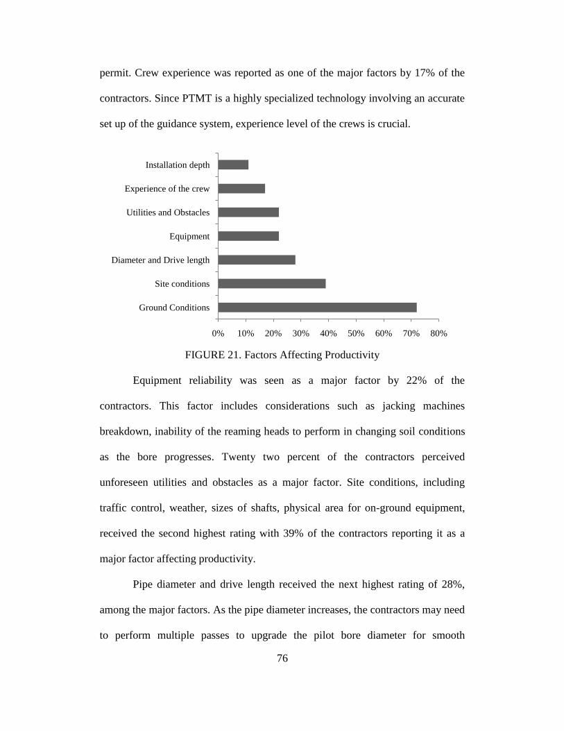
76
permit. Crew experience was reported as one of the major factors by 17% of the
contractors. Since PTMT is a highly specialized technology involving an accurate
set up of the guidance system, experience level of the crews is crucial.
FIGURE 21. Factors Affecting Productivity
Equipment reliability was seen as a major factor by 22% of the
contractors. This factor includes considerations such as jacking machines
breakdown, inability of the reaming heads to perform in changing soil conditions
as the bore progresses. Twenty two percent of the contractors perceived
unforeseen utilities and obstacles as a major factor. Site conditions, including
traffic control, weather, sizes of shafts, physical area for on-ground equipment,
received the second highest rating with 39% of the contractors reporting it as a
major factor affecting productivity.
Pipe diameter and drive length received the next highest rating of 28%,
among the major factors. As the pipe diameter increases, the contractors may need
to perform multiple passes to upgrade the pilot bore diameter for smooth
0% 10% 20% 30% 40% 50% 60% 70% 80%
Ground Conditions
Site conditions
Diameter and Drive length
Equipment
Utilities and Obstacles
Experience of the crew
Installation depth

77
installation of the final product pipe. Also, as previously discussed, as the drive
length increases there are chances of condensation in the pilot tube cavity causing
the loss of optical vision for the guidance system. Setting up and pumping a dry
inert gas to clear the optical path will most likely cause drives to be delayed and
increase costs.
Drive Lengths and Pipe Materials
The contractors were asked to provide the longest length they had installed
in a single drive with pipes of different materials. Fifty percent of the contractors
surveyed reported using vitrified clay pipe on their projects. It was observed that
70% of the contractors that had used PTMT with VCP pipe recorded their longest
drive lengths above 300 feet. This is a good indication of the compressive strength
of the pipe material. Coupled with other advantages of VCP pipe, including high
corrosion resistance and low cost, it is a popular pipe material for PTMT
(Haslinger et. al. 2008). Steel pipe was used by 80% of the contractors on at least
one of their projects. Seventy percent of the contractors that used steel pipe
recorded their longest drives above 400 feet. The longest drive length among the
surveyed projects was 550 feet where a contractor used steel pipe. It is likely that
some of the projects using steel pipe are large diameter product pipes executed
using the PTMT-Auger Boring hybrid method. Only two of the contractors
reported installing concrete pipes with PTMT. The longest drive length, as
reported by one contractor, using concrete pipes was 502 feet. It is interesting to
note that a drive length of 400 feet had been achieved with HDPE pipe using the
hybrid PTMT-Horizontal directional drill method.

78
Pilot Tube Microtunneling Methods
The three main variants of PTMT, as previously discussed, are two phase,
three phase and three phase with a powered cutting head (PCH). The results show
that 20% of the contractors had used powered head equipment on their projects.
Thirty three percent of the contractors were experienced only with the two phase
technology while 27% of the contractors were experienced only with three phase.
Thirty three percent of the contractors had used both two phase and three phase
methods on their projects. Of the total PTMT project surveyed, 51% were two
phase projects while 47% were three phase projects. Only 1% of the surveyed
projects used powered head equipment. It is interesting to note that while 20% of
the contractors had experience with PCH, these projects accounted for only 1% of
the total PTMT project surveyed. Basing on this trend, it may be concluded that
while the contractors are experienced with the technology, not many projects
require the use of powered cutting equipment.

79
CHAPTER 4
CONCLUSIONS
The traditional method of installing underground pipelines using trenching
techniques may be unsafe, time consuming, expensive and disruptive to regular
on-ground activities such as vehicular and pedestrian movement. As an alternative
to the traditional methods, many new technologies have emerged over the years
that minimize the need for trench work. These technologies are together referred
to as trenchless technologies. Pilot Tube Microtunneling (PTMT) is a relatively
new form of trenchless technology. PTMT was introduced to North America in
the mid 1990s and has been emerging as a popular methodology to install gravity
sewers accurately on line and grade. Most of the existing literature on PTMT is
restricted to project specific case studies and therefore there is an emerging need
for further research about the technology.
Contributions made to the field of Pilot Tube Microtunneling through this
thesis include:
1) The documentation of the methodology, equipment, practices,
applicability, capabilities and limitations associated with this technology
through review of existing literature and consultation with industry
experts.
2) Analysis of the responses to a survey questionnaire, that was sent out to
the practitioners of PTMT across North America, to obtain insights into
the industry trends, business practices, risks, and applications of the
technology, among other areas.

80
This research, through the documentation of PTMT methodology and
practices, is expected to serve as a good beginning point of reference to academics
for further research of the technology. Cities and municipalities may find this
research valuable in forming an understanding of the technology, its applicability
and risk factors. Contractors working with the technology would find this research
helpful in identifying comprehensive industry trends as generated from the survey
responses. This information would serve the contractors in positioning and
comparing themselves with the practices of the rest of the industry.
4.1 Summary of Survey Results
The results and analysis presented in this thesis were derived from 22
responses to the survey questionnaires that were sent out to contractors that own
PTMT equipment and provide services for the installation of underground pipe
utilizing PTMT methods. Surveys were returned from a good geographical spread
across United States and Canada. The survey respondents together had completed
450 projects using PTMT among 5770 trenchless projects between 2006 and
2010. As revealed by the survey data, PTMT method is well suited for installation
of pipe up to 40 inch outside diameter, with drive lengths in the range of 550 feet.
Previously available literature on the technology put the drive lengths in 300 feet
to 400 feet range.
The respondents were diverse in terms of their experience with PTMT,
ranging from two to 11 years. Three respondents had an experience of 10 years
and above with the technology. The data revealed that 50% of the respondents had
started using PTMT within the last five years, showing the increasing prominence

81
of this technology. However, a majority of the respondents had been providing
services with other trenchless technologies for many years. Eighty percent of the
respondents indicated that they routinely provide services using auger boring.
Auger boring, with a share of 53% among all the trenchless projects completed by
the respondents between 2006 and 2010, was the most used method by the
contractors. It was observed that for approximately 75% of the respondents PTMT
projects formed less than 25% of their total trenchless project portfolio. The data
revealed that PTMT projects grew by approximately 110% for the period 2006 to
2010, among the surveyed respondents, despite the adverse economic conditions.
This statistic reveals the increasing popularity of this technology.
As suggested by the data, a majority of projects utilizing PTMT were for
city or municipal governments. The respondents acted as subcontractors on 80%
of the projects completed with PTMT. The respondents together owned 47
jacking frames, with 83% of those rigs being able to install pipes up to 38 inch
outside diameter. A majority of the respondents owned between one and two
jacking frames. Approximately 20% of the contractors indicated that they do not
own any jacking frames, but still provide services with the technology using
rented equipment. Eighty six percent of the 450 projects completed using PTMT
were for sanitary and storm sewers. Eighty three percent of the projects were
obtained using competitive bidding, while 55% of the respondents indicated that
they used the unit price contract method on all of their PTMT projects.
While PTMT was designed as an independent installation technology, it
acts as a complementary technology to, pipe ramming, auger boring and

82
horizontal directional drilling, in providing an accurate pilot bore for the main
installations. PTMT is widely used in conjunction with auger boring, with 85% of
the respondents reporting that they had completed at least one project using this
hybrid method. Integration of PTMT and HDD expands the technology’s pipe
material options to using tensile pipes such as PVC and HDPE. Twenty five
percent of the respondents indicated that they had used such a method.
Soil conditions were cited as the highest risk associated with PTMT
projects, which would be expected for underground construction. The highest
risk was encountering cobbles and boulders, followed by sand and gravel soils.
These granular soils are very difficult to displace during the pilot tube drilling and
can also cause problems when installing casing and removing spoils. Installation
in soils with high groundwater table was identified as a moderate risk to high risk.
The technology’s capabilities are marginal when installing in medium to dense
sands below the water table. The lowest risks associated with PTMT were causing
damage to the product pipe and damaging adjacent utilities during an installation
reaffirming the popularity of PTMT as one of the most accurate trenchless
method. Ground conditions were identified by 72% of the contractors as a major
factors affecting productivity of PTMT installations. Approximately 40% of the
respondents identified site factors, such as traffic control, weather conditions, lay
down area, and size of shafts, as a major factor affecting productivity.
As suggested by the data, the most predominantly used pipe materials with
PTMT are steel and Vitrified Clay Pipe (VCP). Eighty percent of the contractors
reported that they had used steel pipe on at least one of their projects. The longest

83
drive lengths recorded using VCP and steel pipes were 343 feet and 550 feet
respectively. A drive length of 400 feet was recorded with HDPE when PTMT
was used in conjunction with HDD. Approximately 51% of the total PTMT
projects completed by the contractors were executed using the two-step method,
while 48% used the three-step method. Powered heads were used on only 1% of
the projects.
The pilot tube microtunneling method while relatively new to North
America, has seen an increase in utilization between 2006 and 2010, while more
traditional methods of trenchless installation have seen a minor decrease in
utilization over the same time among the surveyed contractors. This technology is
ideal for the installation of pipe on tight line and grade for installation lengths
generally utilized between manholes in a municipal setting. As the need to replace
buried pipe infrastructure in urban areas increase, it is expected that pilot tube
microtunneling will see an increase in utilization due to its highly accurate
installations, low impact and small footprint of operation.
4.2 Areas for Future Research
This section presents the author’s recommendations for further research
into the area of pilot tube microtunneling.
4.2.1 Practice of PTMT Projects
With the increasing popularity of PTMT coupled with a shortage of
documented literature in the area, there is a need for further research into the
procedures and guidelines to be used in employing this technology. This research
could also include studying the best practices for realizing PTMT installations in

84
an efficient and a sustainable manner. Currently, there are no standard set of
PTMT specifications in use by cities and municipalities. Thorough research into
the areas of 1) applicability in various soils conditions; 2) pipe materials; 3)
diameters; 4) risk factors; 5) drive lengths; 6) ground movements; and 7) appraisal
of the variants of the technology, is necessary in establishing industry standards.
Development of such specifications may encourage more city and municipal
governments to use this technology for their sewer installation needs.
4.2.2 Costs and Productivity
It is felt that there is a need for researching the costs and productivity rates
associated with PTMT installations to serve as a reference to the contractors and
utility owners in estimating the construction costs and project schedules. A survey
may be instituted for this purpose. It is anticipated that the survey developed for
this research would serve as a good reference for future industry studies on
PTMT. However, it is noticed in consultation with industry experts that
contractors might be hesitant in providing cost data as safeguarding their bidding
and price information is critical to their future project pursuits. Since most of
PTMT installations are for the city and municipal governments, the bidding and
project cost data could be available in public domain. However, if this method is
employed, it may be challenging to identify project specific factors such as
geotechnical conditions, impediments to project success, and unforeseen
circumstances, to name a few. Ground conditions, diameter, number of pits/shafts,
water table, location of the project to characterize traffic management factors,

85
might be used as variables to categorize projects for analyzing cost and
productivity data.
4.2.3 Comparison with Other Methods of Pipe Installation
Cities and muncipal governments now have multiple options in selecting
an efficient method for their sewer installation projects. The popular methods for
this project type include: 1) microtunneling; 2) auger boring; 3) pilot tube
microtunneling; 4) open-trench method. These methodologies widely differ in
terms of their applicability, capabilities, and associated costs. Selection of an
efficient method based on project specific considerations is crucial for the success
of any project. With the advent of PTMT as an efficient, accurate and economical
method, within its range of applicability, there is a need for further research to
compare this technology with the other applicable methods. A simulation tool
may be developed to help the city and municipal governments in selecting an
efficient installation method based on variables including, but not limited to: 1)
ground conditions; 2) product pipe diameter; 3) pipe material; 4) depth of
installation; 5) drive length; 6) project costs; 7) social costs.

86
REFERENCES
Abbott, D.G. (2005). Practical Considerations in the Selection and for the
Use of Microtunneling vs Other Trenchless Techniques. Proceedings of No-
Dig 2005 Conference, NASTT, Orlando, FL.
Abraham, D., Baik, H.S., Gokhale, S. (2002). Development of a Decision Support
System for Selection of Trenchless Technologies to Minimize Impact of
Utility Construction on Roadways. Project No: C-36-67HHH, Joint
Transportation Research Program, Indiana Department of Transportation and
the U.S. Department of Transportation Federal Highway Administration.
Akkerman Inc., Guided Boring Machine (GBM) Technical Manual.
http://www.akkerman.com/. Access date: 08/01/2011.
Allouche, E.N., Ariaratnam, S.T., AbouRizk, S.M. (2000). Multi-Dimensional
UtilityModel for Selection of a Trenchless Construction Method. Proceedings
Construction Congress VI, February 20–22. ASCE, Orlando, FL. pp. 543–
553.
Allouche, E. N., Ariaratnam, S. T., Lueke, J. S. (2000). Horizontal Directional
Drilling: Profile of an Emerging Industry. Journal of Construction
Engineering and Management, ASCE, 126(1), pp. 68-76.
American Society of Civil Engineers (2009). 2009 Report Card for America’s
Infrastructure. http://www.asce.org/reportcard/.
Anderson, L. (2008). Guaranteed Accuracy and Longer Drives: Using PTMTS
with Auger Boring Rigs. Proceedings of No-Dig 2008 Conference, NASTT,
Dallas, TX.
Arbolante, R., Mathy, D. (2005). Microtunneling Construction Challenges on the
Alvarado Boulevard Trunk Sewer Project. Proceedings of No-Dig 2005
Conference, NASTT, Orlando, FL.
Ariaratnam, S. T., Allouche, E. N. (2000). Suggested practices for installations
using horizontal directional drilling. Practice Periodical of Structural Design
and Construction, 5(4), pp. 142–149.
Ariaratnam, S.T., Lueke, J.S., Allouche, E.N. (1999). Utilization of Trenchless
Construction Methods by Canadian Municipalities. Journal of Construction
Engineering and Management, ASCE, 125(2), pp. 76-86.

87
Ariaratnam, S.T., Sihabuddin, S.S. (2009). Comparison of Emitted Emissions
Between Trenchless Pipe Replacement and Open Cut Utility Construction.
Journal of Green Building, 4(2), pp. 126-140.
Boschert, J. (2006). Pilot Tube Microtunneling Explodes in the U.S. Using
Vitrified Clay Jacking Pipe. Proceedings of No-Dig 2006 Conference,
NASTT, Nashville, TN.
Boschert, J. (2007). Pilot tube microtunneling explodes in the U.S. using vitrified
clay jacking pipe. Pipelines 2007 Advances and Experiences with
Trenchless Pipeline Projects, ASCE, Boston, MA.
Boyce, G., Camp, C. (2008). New Installation Methods Good Practices. Seminar
Prior to Alberta Trenchless Conference 2008, Edmonton, Alberta, Canada.
Bruce, M.H. (2002). Pilot Tube Microtunneling’s Cost Effective Advantage for
New Installation of Urban Sewers. Pipelines 2002 beneath our Feet:
Challenges and Solutions - Proceedings of the Pipeline Division Specialty
Conference, Cleveland, OH, August 4-7, 2002.
Bruce, M. (2008). Innovative Methods Tame Multi-Diameter Microtunneling
Project. Proceedings of No-Dig 2008 Conference, NASTT, Dallas, TX.
Edgerton, W.W. (2008). Recommended Contract Practices for Underground
Construction. Underground Construction Association of the Society for
Mining Metallurgy and Exploration., Englewood, CO.
Everett, J. G., Frank, P. B. Jr. (1996). Costs of accidents and injuries to the
Construction Industry. Journal of Construction Engineering and
Management, ASCE, 122(2), pp. 158-164.
Farouz, E., Doyle, M. J., Landers, P. (2010). Case History: Pilot Tube Method
Solves Basement Flooding Problem. Proceedings of No-Dig 2010, NASTT,
Chicago, IL.
Fisher, T. (2003). Guided boring method –a A case study. Proceedings of the
ASCE International Conference on Pipeline Engineering and Construction:
New Pipeline Technologies, Security, and Safety, v 2, pp. 1763-1770.
Force, W., Pederson. S., McFadden, S., Tumbleson, R. (2005). City of
Bloomington, Mall of America Sanitary Sewer Improvement Project 2003-
50. Proceedings of No-Dig 2005 Conference, NASTT, Orlando, FL.

88
Gelinas, M., Mathy, D., Rotter, J., Creviston, S., Hooshialsadat, P., Soldat, M.,
Winzler, J.J (2010). One Project, Four Trenchless Methods. Proceedings of
18th Annual Sharing Technologies Seminar, The Northern California Pipe
User’s Group, Berkely, CA.
Haslinger, L., Gill, D., and Boschert, J. (2007). Pilot Tube Microtunneling Project
Parallels the Shore of Lake Erie in Toledo, Ohio: A Case Study.
Proceedings of No-Dig 2007 Conference, NASTT, San Diego, CA.
Iseley, T., Gokhale, S.B. (1997). Trenchless installation of conduits beneath
roadways. NCHRP Synthesis 242, Transportation Research Board, National
Research Council, Washington, D.C.
Jung, J.Y., Sinha, S.K. (2007). Evaluation of Trenchless Technology Methods for
Municipal Infrastructure System. Journal of Infrastructure Systems, ASCE,
13(2), pp. 144-156.
Latorre, C.A., Wakeley, L.D., Conroy, P.J. (2002). Guidelines for Installation of
Utilities Beneath Corps of Engineers Levees Using Horizontal Directional
Drilling. Engineer Research and Development Center, US Army Corp of
Engineers.
McKim, R.A. (1998). Bidding strategies for trenchless technologies. Cost
Engineering, 40(3).
Monier, D. J., and Robinson, F. E. (2001). Apparatus and method for pilot-tube
guided auger boring. United State Patent, Patent No.: US 6,206,109 B1.
Monier, D., Vedder, R. (2000). Small Diameter Sewers by Pilot Tube
Microtunneling. Proceedings of No-Dig 2000 Conference, NASTT,
Anaheim, CA.
Myers, M.B., Stickrod, T.W., Abraham, D.M., Iseley, T. (1991). Microtunneling
Technology for Conduit Construction. Practice Periodical on Structural
Design and Construction, ASCE, 4(2), pp. 56-63.
Najafi, M., and Gokhale, S.B. (2005). Trenchless technology: pipeline and utility
design, construction, and renewal. McGraw-Hill, New York.
National Highway Traffic Safety Administration (NHTSA) (2010). Fatality
Analysis Reporting System (FARS). http://www.nhtsa.goc/fars/
Neider, G. (2006). Optical guided auger boring: latest developments and new
fields of application. Proceedings of No-Dig International 2006 Conference
and Exhibition, ISTT, Brisbane, Australia.
89
North American Society for Trenchless Technology (NASTT). Glossary of
Terms. www.nastt.org/glossary/. Access date: 08/01/2011
Powers, J.P., Corwin, A.B., Schmall, P.C., Kaeck, W.E. (2007). Construction
Dewatering and Ground Water Control. John Wiley & Sons, Inc., Hoboken,
New Jersey.
Ramos, M. (2009). Field Challenges and Successes with Pilot Tube
Microtunneling. Proceedings of No-Dig 2009 Conference, NASTT, Toronto,
Ontario, Canada.
Ramos, M. L., Stephl, M. (2008). Pilot Tube Microtunneling in Alaska.
Proceedings of No-Dig 2008 Conference, NASTT, Dallas, TX.
Rayman, M., Najafi, M., Hashemi, B. (2008). Cost Comparison of Open-cut and
Trenchless Methods for Renewing Sewer Lines. Underground Infrastructure
Management, Sep/Oct 2008.
Rehan, R., Knight, M. (2007). Do Trenchless Pipeline Construction Methods
Reduce Greenhouse Gas Emissions?. Center for the Advancement of
Trenchless Technologies (CATT), Department of Civil and Environmental
Engineering, University of Waterloo, Ontario, Canada, Sep 2007.
Sewing, E., Luth, M., Boschert, J. (2009). The First Major Pilot Tube
Microtunneling Project in the St. Louis Metropolitan Area. Proceedings of
No-Dig 2009 Conference, NASTT, Toronto, Ontario, Canada.
The International Society for Trenchless Technology (ISTT). Glossary of Terms.
http://www.istt.com/. Access date: 08/01/2011
The International Society for Trenchless Technology (ISTT). Guided Auger
Boring (Pilot pipe jacking). http://www.istt.com/. Access date: 08/01/2011.
United Kingdom Society for Trenchless Technology (UKSTT) (2011). Achieving
Great Things in Pipe Jacking. Trenchless Works, UKSTT, Issue 58.
United States General Accounting Office (2004). Water Infrastructure –
Comprehensive Asset Management Has Potential to Help Utilities Better
Identify Needs and Plan Future Investments. Report to the Ranking Minority
Member, Committee on Environment and Public Works, U.S. Senate.
Wallbom, M.R., Huber, J. (2008). Calvert Cliff Nuclear Power Plant utilizes
Trenchless Technologies Under Extreme and Challenging Conditions.
Proceedings of No-Dig 2008 Conference, NASTT, Dallas, TX.

90
Woodroffe, N.J.A., Ariaratnam, S.T. (2009). Contractor Perspective on Factors
for Evaluating Installation Options for Small-Diameter Utilities. Journal of
Construction Engineering and Management, ASCE, 135(2), pp. 75-87.
Zhao, J.Q., Rajani, B. (2002). Construction and Rehabilitation Costs for Buried
Pipe with a Focus on Trenchless Technologies. Research Report No. 101,
Institute for Research in Construction, Ottawa, Canada.

91
APPENDIX A
SURVEY QUESTIONNAIRE

92
Part 1: Company Profile
1. List the States and Provinces that you have completed Pilot Tube
Microtunneling projects:_______________________________________________
2. How many years has your company been using Pilot Tube Microtunneling?:
3. Approximately, how many projects has your company completed over the last
5 years using each of the following technologies:
2006 2007 2008 2009 2010
Pilot Tube Microtunneling
Horizontal Directional Drilling
Microtunneling
Pipe Ramming
Auger Boring
Pipe Jacking
4. Typical Clients (what % falls under each category):
City or Municipal Government %
State or Provincial Government %
Federal Government %
Private %
5. Percent of jobs undertaken as a general contractor: ________ %
Percent of jobs undertaken as a subcontractor: ________ %
6. What sizes of PTMT machines/jacking frames do you own?:
Maximum Installed Pipe Diameter Number of Units
12” or less
13” to 25”
26” to 38”
39” to 51”
Greater than 52”
7. Percent of jobs completed with rented PTMT machines/frames ____ %
Percent of jobs completed with rented PTMT equipment/tubes ______ %
Contact Information:
Name: ______________________ Email:________________________
Company: ____________________________________________________
All responses will be held in confidence – Contact Info needed to send results of
the survey.
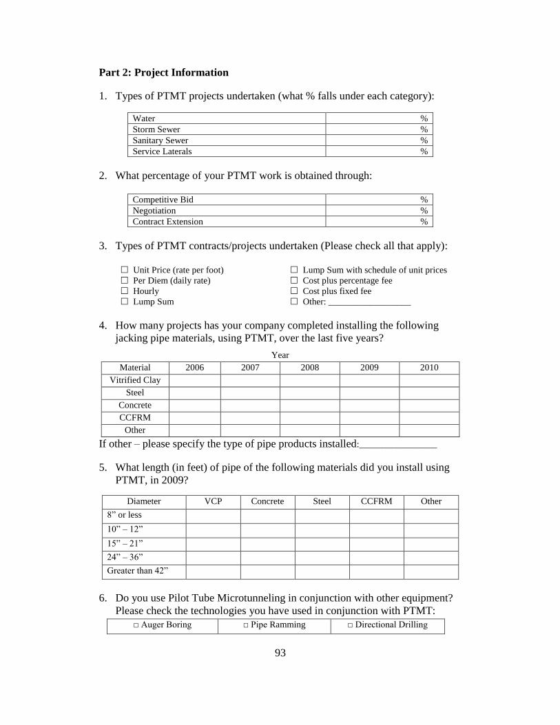
93
Part 2: Project Information
1. Types of PTMT projects undertaken (what % falls under each category):
Water %
Storm Sewer %
Sanitary Sewer %
Service Laterals %
2. What percentage of your PTMT work is obtained through:
Competitive Bid %
Negotiation %
Contract Extension %
3. Types of PTMT contracts/projects undertaken (Please check all that apply):
Unit Price (rate per foot) Lump Sum with schedule of unit prices
Per Diem (daily rate) Cost plus percentage fee
Hourly Cost plus fixed fee
Lump Sum Other: __________________
4. How many projects has your company completed installing the following
jacking pipe materials, using PTMT, over the last five years?
Year
Material 2006 2007 2008 2009 2010
Vitrified Clay
Steel
Concrete
CCFRM
Other
If other – please specify the type of pipe products installed:_________________
5. What length (in feet) of pipe of the following materials did you install using
PTMT, in 2009?
Diameter VCP Concrete Steel CCFRM Other
8” or less
10” – 12”
15” – 21”
24” – 36”
Greater than 42”
6. Do you use Pilot Tube Microtunneling in conjunction with other equipment?
Please check the technologies you have used in conjunction with PTMT:
□ Auger Boring □ Pipe Ramming □ Directional Drilling

94
Part 3: Proect Planning and Construction Risks
1. When considering the duration of a project, what percentage of time is spent
on the following stages of a PTMT the project:
Planning (Prior to going to site) %
Site preparation %
Installation of Pilot Tubes, Casing, and Product Pipe %
Site Restoration %
2. Please rate the risk associated with the following factors and conditions:
Low
Risk
High
Risk
Damaging adjacent utilities during installations 1 2 3 4 5
Damaging product pipe during installation 1 2 3 4 5
Ground movement damaging surface
pavements
1 2 3 4 5
Maintaining proper grade 1 2 3 4 5
High groundwater table 1 2 3 4 5
Installations in sand or gravel soils 1 2 3 4 5
Installations in clay or silt soils 1 2 3 4 5
Cobbles/boulders stopping an installation 1 2 3 4 5
3. Please list some factors that affect productivity on PTMT projects: _________________________________________________________
_________________________________________________________
4. What is the longest drive length that you have installed in a single drive for
each of the following types of pipe?
Pipe Material VCP Concrete Steel CCFRM Other
Longest Drive Length
5. Check all the methods of PTMT that you have used, and provide the diameter
ranges for each method utilized. Also fill in the percentage of PTMT projects
that each of the methods has been used on.
Method Smallest
Diameter
Largest
Diameter
% of Projects
□ Two Phase
□ Three Phase
□ Three Phase with PCH / PRH

95
APPENDIX B
LIST OF RESPONDENTS

96
1) Aaron Enterprises, Inc., York, PA
2) Armadillo Underground Inc., Salem, OR
3) B Trenchless, Henderson, CO
4) Blevins Road Boring, Hudson, FL
5) Bore Master, Inc., Pewaukee, WI
6) Bradshaw Constrcution Corporation, Elliot City, MD
7) Brannan Construction Company, Denver, CO
8) Calgary Tunneling, Calgary, AB, Canada
9) Claude H. Nix. Construction Co., Inc., Ogden, UT
10) Frank Coluccio Construction, Seattle, WA
11) Kamploops Augering & Boring Ltd., Kamploops, BC, Canada
12) Magnum Tunneling & Boring, LLC., Houston, TX
13) Midwest Mole, Inc., Indianapolis, IN
14) North Core, Fargo, ND
15) Pacific Boring, Inc., Caruthers, CA
16) Riley Contracting, Inc., Norwalk, OH
17) Roddie, Inc., Morgan Hill, CA
18) Specialized Services Co., Phoenix, AZ
19) Super Excavators, Inc., Menomonee falls, WI
20) T&D Trenchless, Murrieta, CA
21) Unknown* (* contractor filled out the survey but did not provide identity)
22) Wayne Arnold Road Boring Co., Smackover, AR