pilot’s guide kln 90b kln-90b manual.pdf · kln 90b pilot’s guide 006-08773-0000 for kln 90bs...
TRANSCRIPT

KLN 90BBendix/King®
TSO’d GPS Navigation System
Pilot’s Guide
ORS 20 A

A
AlliedSignal, Inc.Commercial Avionics Systems400 North Rogers RoadOlathe, Kansas 66062-1294FAX 913-791-1302Telephone: (913) 782-0400
006-08773-0000Rev.1 05/97

i Rev 1
KLN 90B PILOT’S GUIDE
006-08773-0000
for KLN 90Bs with
OPERATIONAL REVISION STATUS (ORS) 20
May, 1997
IMPORTANT: Special installation procedures must befollowed in order for the KLN 90B to be certified for IFR use.Consult the KLN 90B Flight Manual Supplement for theoperating limitations of this unit.
For Important Database Update
Information
See Section 2.7

ii Rev 1
THIS PAGE INTENTIONALLY LEFT BLANK

TOC-1 Rev 1
INTRODUCTION ...........................................................................................................................................................IPREVIEW OF OPERATION ............................................................................................................................................IICHAPTER 1 - KLN 90B SYSTEM COMPONENTS....................................................................................................1-1CHAPTER 2 - DATA BASE .........................................................................................................................................2-1
2.1 FUNCTIONS OF THE DATA BASE .................................................................................................................2-12.2 DATA BASE COVERAGE AREAS AND CONTENTS ..................................................................................2-12.3 USE OF ICAO IDENTIFIERS ...........................................................................................................................2-32.4 UPDATING THE DATABASE ..........................................................................................................................2-3
2.4.1 Computer Updating of the Database ..................................................................................................2-42.4.2 Cartridge Exchange Updating of the Database ..................................................................................2-7
2.5 USER DEFINED DATABASE ..........................................................................................................................2-82.6 INTERNAL MEMORY BACKUP BATTERY ....................................................................................................2-82.7 DATABASE UPDATE SERVICE OPTIONS.....................................................................................................2-8
CHAPTER 3 - LEVEL 1 OPERATION.........................................................................................................................3-13.1 COVERAGE AREA ..........................................................................................................................................3-13.2 TURN-ON AND SELF TEST ............................................................................................................................3-33.3 DISPLAY FORMAT ..........................................................................................................................................3-93.4 BASIC OPERATION OF PANEL CONTROLS ..............................................................................................3-11
3.4.1 Page Selection ..................................................................................................................................3-123.4.2 Data Entry .........................................................................................................................................3-143.4.3 Alternative Waypoint Data Entry Method .........................................................................................3-153.4.4 The Duplicate Waypoint Page ..........................................................................................................3-15
3.5 MESSAGE PAGE ...........................................................................................................................................3-163.6 INITIALIZATION AND TIME TO FIRST FIX ..................................................................................................3-173.7 SELECTING WAYPOINTS ............................................................................................................................3-20
3.7.1 Selecting Waypoints By Identifier .....................................................................................................3-203.7.2 Selecting Waypoints By Scanning ....................................................................................................3-213.7.3 “Nearest” And “Complete” Waypoint Scan Lists ..............................................................................3-223.7.3.1 Nearest Airports In An Emergency ...............................................................................................3-233.7.3.2 Continuous Display Of Nearest Airport .........................................................................................3-243.7.4 Selecting Waypoint By Name Or City ...............................................................................................3-24
3.8 DIRECT TO OPERATION ..............................................................................................................................3-273.8.1 Direct To-Procedure 1 ......................................................................................................................3-283.8.2 Direct To-Procedure 2 ......................................................................................................................3-283.8.3 To Recenter The D-Bar ....................................................................................................................3-293.8.4 To Proceed Direct To Another Waypoint .........................................................................................3-293.8.5 Cancelling Direct To Operation ........................................................................................................3-293.8.6 Waypoint Alerting For Direct To Operation ......................................................................................3-29
3.9 THE NAVIGATION PAGES ...........................................................................................................................3-313.9.1 The Navigation 1 Page (NAV 1) .......................................................................................................3-313.9.2 The Super NAV 1 Page ...................................................................................................................3-323.9.3 The Navigation 2 Page (NAV 2) .......................................................................................................3-323.9.4 The Navigation 3 Page (NAV 3) .......................................................................................................3-323.9.5 The Navigation 4 Page (NAV 4) .......................................................................................................3-343.9.6 The Navigation 5 Page (NAV 5) .......................................................................................................3-343.9.7 The Super NAV 5 Page ....................................................................................................................3-36
3.10 SPECIAL USE AIRSPACE ALERT ..............................................................................................................3-39
TABLE OF CONTENTS

TOC-2 Rev 1
3.11 VIEWING THE WAYPOINT PAGES ...........................................................................................................3-423.11.1 Airport Pages ..................................................................................................................................3-423.11.2 The Airport 1 Page (APT 1) ............................................................................................................3-423.11.3 The Airport 2 Page (APT 2) ............................................................................................................3-433.11.4 The Airport 3 Page (APT 3) ............................................................................................................3-433.11.5 The Airport 4 Page (APT 4) ............................................................................................................3-453.11.6 The Airport 5 Page (APT 5) ............................................................................................................3-473.11.7 The Airport 6 Page (APT 6) ............................................................................................................3-483.11.8 The Airport 7 Page (APT 7) ............................................................................................................3-493.11.9 The Airport 8 Page (APT 8) ............................................................................................................3-493.11.10 The VOR Page .............................................................................................................................3-493.11.11 The NDB Page ..............................................................................................................................3-503.11.12 The Intersection Page (INT) .........................................................................................................3-503.11.13 The Supplemental Waypoint Page (SUP) ....................................................................................3-51
3.12 FREQUENCIES FOR NEAREST FLIGHT SERVICE STATIONS ..............................................................3-523.13 FREQUENCIES FOR AIR ROUTE TRAFFIC CONTROL CENTERS (ARTCC) .......................................3-523.14 VIEWING AND SETTING THE DATE AND TIME .......................................................................................3-533.15 ALTITUDE ALERTING .................................................................................................................................3-553.16 HEIGHT ABOVE AIRPORT ALERT ............................................................................................................3-583.17 REMOTE MOUNTED ANNUNCIATORS ....................................................................................................3-593.18 SAMPLE TRIP ..............................................................................................................................................3-60
3.18.1 Pre-Departure .................................................................................................................................3-603.18.2 Enroute ...........................................................................................................................................3-603.18.3 Terminal Area .................................................................................................................................3-61
CHAPTER 4 - LEVEL 2 OPERATION.........................................................................................................................4-14.1 CREATING AND MODIFYING FLIGHT PLANS .............................................................................................4-1
4.1.1 Creating A Flight Plan .........................................................................................................................4-24.1.2 Activating A Numbered Flight Plan .....................................................................................................4-34.1.3 Adding A Waypoint To A Flight Plan ..................................................................................................4-44.1.4 Deleting A Waypoint From A Flight Plan ............................................................................................4-54.1.5 Deleting Flight Plans ...........................................................................................................................4-54.1.6 Storing FPL 0 As A Numbered Flight Plan .........................................................................................4-6
4.2 OPERATING FROM THE ACTIVE FLIGHT PLAN .........................................................................................4-74.2.1 General Procedures ............................................................................................................................4-74.2.2 Turn Anticipation And Waypoint Alerting ............................................................................................4-84.2.3 Viewing The Waypoint Pages For The Active Flight Plan Waypoints .............................................4-104.2.4 Combining Direct To And Flight Plan Operation ..............................................................................4-104.2.5 The Distance/Time Pages ................................................................................................................4-114.2.6 The Distance/Time 1 Page (D/T 1) ...................................................................................................4-114.2.7 The Distance/Time 2 Page (D/T 2) ...................................................................................................4-124.2.8 The Distance/Time 3 Page (D/T 3) ...................................................................................................4-124.2.9 The Distance/Time 4 Page (D/T 4) ...................................................................................................4-13
4.3 SAMPLE TRIP ................................................................................................................................................4-154.3.1 Pre-Departure ...................................................................................................................................4-164.3.2 Enroute ..............................................................................................................................................4-16
CHAPTER 5 - LEVEL 3 OPERATION.........................................................................................................................5-15.1 TRIP PLANNING ..............................................................................................................................................5-1
5.1.1 The Trip Planning 0 Page (TRI 0) .......................................................................................................5-25.1.2 The Trip Planning 1 And Trip Planning 2 Pages (TRI 1 and TRI 2) ..................................................5-35.1.3 The Trip Planning 3 And Trip Planning 4 Pages (TRI 3 and TRI 4) ..................................................5-5

TOC-3 Rev 1
5.1.4 The Trip Planning 5 And Trip Planning 6 Pages (TRI 5 and TRI 6) ..................................................5-65.2 ADVISORY VNAV OPERATION .....................................................................................................................5-7
5.2.1 VNAV For Direct To Operation ...........................................................................................................5-75.2.2 VNAV For Flight Plan Operation .........................................................................................................5-95.2.3 VNAV From the Super NAV 5 Page ...................................................................................................5-9
5.3 CALCULATOR PAGES ..................................................................................................................................5-105.3.1 The Calculator 1 Page (CAL 1) ........................................................................................................5-105.3.2 The Calculator 2 Page (CAL 2) ........................................................................................................5-115.3.3 The Calculator 3 Page (CAL 3) ........................................................................................................5-125.3.4 The Calculator 4 Page (CAL 4) ........................................................................................................5-125.3.5 The Calculator 5 Page (CAL 5) ........................................................................................................5-135.3.6 The Calculator 6 Page (CAL 6) ........................................................................................................5-145.3.7 The Calculator 7 Page (CAL 7) ........................................................................................................5-15
5.4 USER-DEFINED WAYPOINTS .....................................................................................................................5-165.4.1 Creating An Airport User Waypoint ..................................................................................................5-165.4.2 Creating A VOR User Waypoint .......................................................................................................5-185.4.3 Creating An NDB User Waypoint .....................................................................................................5-185.4.4 Creating Intersection Or Supplemental User Waypoints .................................................................5-185.4.5 Deleting User-Defined Waypoints ....................................................................................................5-20
5.5 REFERENCE WAYPOINTS ..........................................................................................................................5-215.6 CENTER WAYPOINTS ..................................................................................................................................5-25
5.6.1 Creating Center Waypoints And Inserting Them in Flight Plans ......................................................5-255.6.2 Viewing the Center Waypoints After Insertion Into A Flight Plan .....................................................5-265.6.3 Creating Center Waypoints After Modifying A Flight Plan ...............................................................5-27
5.7 PROGRAMMING THE TURN-ON PAGE ......................................................................................................5-285.8 THE STATUS PAGES ...................................................................................................................................5-29
5.8.1 Determining The Status Of The GPS Signals ..................................................................................5-295.8.2 Determining KLN 90B Software Status And Operational Time ......................................................5-31
5.9 MODES OF OPERATION ..............................................................................................................................5-325.9.1 Selecting The Leg Mode Or The OBS Mode ...................................................................................5-325.9.2 The Leg Mode ...................................................................................................................................5-335.9.3 The OBS Mode .................................................................................................................................5-345.9.4 Switching From The Leg Mode To The OBS Mode .........................................................................5-365.9.5 Switching From The OBS Mode To The Leg Mode .........................................................................5-365.9.6 Going Direct-To A Waypoint While in the OBS Mode ......................................................................5-375.9.7 Activating A Waypoint While In The OBS Mode ..............................................................................5-375.9.8 Changing the CDI Scale Factor ........................................................................................................5-37
5.10 THE FUEL MANAGEMENT PAGES ...........................................................................................................5-395.10.1 The Other 5 Page (OTH 5) .............................................................................................................5-395.10.2 The Other 6 Page (OTH 6) .............................................................................................................5-415.10.3 The Other 7 Page (OTH 7) .............................................................................................................5-415.10.4 The Other 8 Page (OTH 8) ............................................................................................................5-41
5.11 THE AIR DATA PAGES ..............................................................................................................................5-425.11.1 The Other 9 Page (OTH 9) .............................................................................................................5-435.11.2 The Other 10 Page (OTH 10) .........................................................................................................5-43
5.12 OPERATION OUTSIDE THE PRIMARY COVERAGE AREA ....................................................................5-445.13 OPERATION WITHOUT A DATA BASE CARTRIDGE ..............................................................................5-445.14 USING THE TAKE-HOME MODE ...............................................................................................................5-46

TOC-4
CHAPTER 6 - LEVEL 4 OPERATION.........................................................................................................................6-16.1 NON-PRECISION APPROACH OPERATIONS ..............................................................................................6-1
6.1.1 Selecting An Approach .......................................................................................................................6-46.1.2 Interpreting What You See .................................................................................................................6-56.1.3 Changing or Deleting An Approach Once Loaded Into The Flight Plan ............................................6-76.1.4 Example Approach: No Procedure Turn ............................................................................................6-86.1.5 Example Approach: Off-Airport Navaid ............................................................................................6-106.1.6 Example Approach: Radar Vectors ..................................................................................................6-126.1.7 Example Approach: On-Airport Navaid ............................................................................................6-146.1.8 Example Approach: DME Arc ...........................................................................................................6-166.1.9 Approach Problems ..........................................................................................................................6-19
6.2 SID/STAR PROCEDURES ............................................................................................................................6-216.2.1 Selecting A SID .................................................................................................................................6-216.2.2 Selecting A STAR .............................................................................................................................6-226.2.3 Editing a SID or STAR ......................................................................................................................6-236.2.4 Example of a SID Procedure ............................................................................................................6-256.2.5 Example of a STAR Procedure ........................................................................................................6-26
APPENDIX A - NAVIGATIONAL TERMS...................................................................................................................A-1APPENDIX B - MESSAGE PAGE MESSAGES.........................................................................................................B-1APPENDIX C - STATUS LINE MESSAGES .............................................................................................................C-1APPENDIX D - ABBREVIATIONS ..............................................................................................................................D-1APPENDIX E - SECONDS TO DECIMAL MINUTES ................................................................................................E-1
Rev 1

I
The KLN 90B is an extremely sophisticated navigationaldevice, capable of providing highly accurate navigationover most parts of the world. You will be amazed at allof the navigational and other aeronautical functions thatthe unit can perform. However, you don’t need to mas-ter all of the KLN 90B’s capabilities at once. In just ashort time you will be confidently using it to make yourflying duties easier and more enjoyable. You will learnnew features as you have a need or desire to learnthem and soon will establish the best way of using theKLN 90B to meet your particular flying requirements.
Don’t let the size of this Pilot’s Guide intimidate you! Itis written in plain, simple English instead of “computer-eeze” and it assumes you are not an experienced userof GPS or other types of long range navigation equip-ment. If you are experienced, so much the better. ThisPilot’s Guide also includes hundreds of sample screenfigures and other illustrations to make your learning eas-ier. It is designed so that you can start at the front andprogress in the order presented; however, you maywant to skip around and learn things in your own order.There are several appendices in the back that you mayfind useful from time to time.
As you become proficient with using the KLN 90B, don’tbe tempted to rely on it as the sole means of navigation.A good pilot never relies on just one source of naviga-tion for either VFR or IFR flying. Cross check your posi-tion using VOR, DME, ADF, or other navigationaldevices you may have in the cockpit - including youreyes!
Be sure and keep a copy of this Pilot’s Guide in theaircraft to use as a reference. You never know whenyou may have a question you’ll want to look up.
One last thing. Don’t get so involved in learning to usethe KLN 90B that you forget to fly the aircraft. Be care-ful, and remember to keep a close eye out for otheraircraft.
NOTE: A white border is used around data on some ofthe figures in this Pilot’s Guide to indicate that the datainside the border is flashing. An example of this is fig-ure 3-5 where the white border around the charactersACKNOWLEDGE? and ENT is used to indicate thatboth are flashing.
Rev 1
INTRODUCTION

II
No doubt you are going to read this entire manual justas soon as you possibly can. But just to get an idea ofhow easy the KLN 90B is to operate, the following oper-ational preview is presented. This operational previewassumes the KLN 90B has been properly installed, theunit was previously operational in the same generalgeographical location, and that no peripheral equipmentinterfaced with the KLN 90B (such as external HSIs,CDIs, autopilots, RMIs, fuel flow systems, moving mapdisplay, etc.) is to be used at this time. If you are usingthis operational preview in flight, do so only in good VFRconditions and only with an alternate means of naviga-tion available to cross-check position.
1. Push the power/brightness knob located in theupper right corner of the unit to the “in” position.
2. After a few seconds of warm up, the screen willshow a Turn-On page with the words SELF TESTIN PROGRESS at the bottom of the page. Rotatethe power/brightness knob to select the desiredscreen brightness. After a few seconds the Turn-On page will automatically be replaced with theSelf Test page. (Note: If the KLN 90B is beingused in the take-home mode, a Take-HomeWarning page is displayed before the Self Testpage and must be acknowledged by pressingE.) The Self Test page is recognizable becauseit shows the date and time on the right side. If thedate and time are incorrect by more than 10 min-utes, refer to section 3.2 of this manual. The bot-tom left side of the Self Test page must displayANNUN ON to indicate that the KLN 90B haspassed an internal self test.
In most KLN 90B installations the first two charac-ters of the altimeter setting BARO field will behighlighted in inverse video (dark characters on alight background) on the right side of the screen.This area of inverse video is called the cursor.Use the right inner knob to select the correct firsttwo characters of the altimeter setting. Next, turnthe right outer knob one step clockwise to positionthe cursor over the third character of the altimetersetting. Use the right inner knob to select the cor-rect number. Once again turn the right outer knobone step clockwise to position the cursor over thelast character of the altimeter setting. Use theright inner knob to complete entering the correctaltimeter setting.
Turn the right outer knob clockwise to position thecursor over the word APPROVE? if the cursor isnot there already. Press E to approve the Self
Test page. (Note: If the KLN 90B is installed forVFR only operation, a VFR only warning page isdiplayed after the self test page has beenapproved. This warning page must be acknowl-edged by pressing E .)
3. A Database page is now displayed showing thedate the data base expires or the date it expired.Press E to acknowledge the information dis-played on this page.
4. A page displaying the letters PRESENT POS atthe top will now be on the left side of the screen.In a couple minutes or less, this page will displaythe aircraft’s present position. It shows the posi-tion both in latitude/longitude and in terms of theradial and distance from a nearby VOR. Verifythat the position is correct before proceeding.
5. Press the D button. A page with the wordsDIRECT TO is now displayed on the left.
In step 6 you will enter the ICAO identifier of thedestination airport. The identifier will have a “K”prefix for a Continental U.S. airport, a “C” prefixfor a Canadian airport, or a “P” prefix (in manycases) for an Alaskan airport if the identifier is allletters. For example, LAX becomes KLAX. Forthese countries if the identifier contains any num-bers, there is no prefix. For example, TX04 isentered TX04. For other areas of the world theairport identifier entered should be identical tohow it is charted.
6. Rotate the left inner knob until the first characterof the airport identifier is displayed. Turn the leftouter knob one step clockwise to move the flash-ing segment to the second character position.Rotate the left inner knob to select the secondcharacter of the identifier. Use this procedure toenter the complete airport identifier.
7. Press E. The right side will display a pageshowing the identifier, name and position of theairport just entered. Confirm that the correct air-port is displayed. Press E a second time toapprove the airport data.
8. A Navigation page is now on the right side of thescreen. It displays the distance, ETE, and bearingto the destination airport. In addition, it displaysgroundspeed and a course deviation indicator. Ifthe left inner knob is rotated one step counter-clockwise, you will get an enlarged Navigationpage occupying the entire screen.
Rev 1
PREVIEW OF OPERATION

1-1
A basic KLN 90B system consists of a panel mountedKLN 90B GPS sensor/navigation computer, a data basecartridge, and an antenna. An altitude input is required toobtain full navigation and operational capabilities.Additional system components may be added or inter-faced to the KLN 90B which increase its features and
capabilities. Some of these optional components includean external course deviation indicator (CDI) or HSI, RMI,fuel management system, air data system, ARTEX ELS-10 emergency locator transmitter (ELT), autopilot, andexternal annunciators.
Rev 1
CHAPTER 1 - KLN 90B SYSTEM COMPONENTS
The KLN 90B panel mounted unit contains the GPS sen-sor, the navigation computer, a CRT display, and all con-trols required to operate the unit. It also houses the database cartridge which plugs directly into the back of theunit.
The database cartridge is an electronic memory contain-ing a vast amount of information on airports, navaids,intersections, special use airspace, and other items ofvalue to the pilot. The database is designed to be easilyupdated by the user by using a laptop computer andAlliedSignal furnished 3.5 inch diskettes. The databasemay also be updated by removing the obsolete cartridgeand replacing it with a current one.
AIRCRAFTPOWER
11/33V
KA 92 OR KA 91 ANTENNA
ALTITUDE
COMPATIBLEFUEL
MANAGEMENTSYSTEM
HEADING
AIR DATA
MOVINGMAP
DISPLAYS
ARTEX ELS-10
ELT
AR
INC
429
or
RS
232
INP
UT
ALTITUDE ALERT AUDIO
WPT ALERTMESSAGE
REMOTE ANNUNCIATORS
HSI EHSI CDIOR OR
AUTOPILOT
RMI
OR
CRSR
MSG D CLR ENT
KLN 90B TSOGPSı
CRSR
PUSHONBRT
APTVORNDBINT
SUPL
NAVD/T
ACTVREFCTR
CALCSTAT
SETUPOTHER
NAVFPL
MODETRIP
PULLSCAN
$=KOSH |=KOSH+++++Ê+++++|WITTMANDIS 683nm|GS 193kt|ETE 3:34|N 43^59.06'BRG 303^|W 88^33.42'NAV 1|enr-leg |APT 1
ALT
NGS GS
33
30W
24
21 S15
12E
6
3
ı
NAV HDG
N
S
E
W
TO
FR
33
3024
21 15
126
3
OBS
GS
NAV
ı
ı
N
S
E
W
3330
2421
15 12
63
AD
F
N33
30W
24
21 S15
12E
6
3
ADF
ADF
NAV NAV
B
ALT HDG NAV APR APGS
ALT HDG NAV APR BC APENG
TESTKAP 150
YD
RN RC PC
BC TRIM
ı
DN
UP
ı
MLS
1
AZ 359 12.6 NM
N33
30W
24
21 S15
12E
6
3
ADF 2
11.5
GS
KI 525AEHI 40/50
KI 206
KI 229 KNI 582
RS
232
OU
TP
UT
RS 232INPUT
GRAY CODE
KLN 90B SYSTEM
GPS APR GPS CRSREMOTE SWITCH/ANNUNCIATORS
SE
LE
CT
ED
CO
UR
SE
AR
INC
429
or
RS
232
INP
UT
REQUIRED FOR ALL INSTALLATIONSREQUIRED FOR ALL IFR APPROACH INSTALLATIONSOPTIONAL
LEFT
/RIG
HT
D-B
AR

1-2
Two GPS antennas can be used with the KLN 90B. Oneis the KA91 and the other is the KA 92. The KA 92 isused with new production KLN 90Bs and the KA 91 isused with units that have been upgraded from either aKLN 90 or a KLN 90A. They are “patch” antennasdesigned to always be mounted on the top of the aircraft.
The KLN 90B has analog outputs to drive the left-rightdeviation bar of most mechanical CDIs and HSIs. Inaddition, it has digital outputs to automatically drive thecourse pointer and display flight plan waypoints on theBendix/King EHI 40 and EHI 50 electronic HSIs.
The Bendix/King KI 229 and KNI 582 RMIs may be inter-faced to the KLN 90B to provide a display of magneticbearing to the waypoint.
The NAV mode of the Bendix/King KFC 150, KAP 150,KAP 150H, KAP 100, KFC 200, KAP 200, KFC 250, KFC275, KFC 300, KFC 325, KFC 400 and KFC 500 FlightControl Systems may be coupled to the KLN 90B. Manyother autopilots may also be coupled to the KLN 90B.Actual autopilot performance and capability when coupledto the KLN 90B may vary significantly from one autopilotmodel to another.
Certain Digiflo™ and Miniflo™ fuel management systemsmanufactured by Shadin Co. Inc. as well as certain fuelcomputers manufactured by ARNAV Systems, Inc. andSHELTECH LTD interface with the KLN 90B. Theseinterfaces allow the pilot to view fuel related parameterscalculated by the KLN 90B such as how much fuel will beremaining when the aircraft lands at the destination. Withcertain Shadin fuel management systems it is possible toupdate the fuel on board through the KLN 90B. In thesecases a separate panel mounted interface to the fuelmanagement computer is not required.
Compatible air data systems are available fromBendix/King and Shadin Co. An air data system is capa-ble of providing the KLN 90B with true air speed datawhich is used for wind determination. The Shadin airdata system also will convert heading data from theBendix/King KCS 55A and some other compass systemsto a format that allows wind calculations to be fully auto-matic.
Altitude may be provided to the KLN 90B from an encod-ing altimeter, blind encoder, or one of the air data com-puters mentioned above. Altitude is used as an aid inposition determination when not enough satellites are inview. Altitude is also used in several altitude related fea-tures such as three dimensional special use airspacealerting, height above airport, and altitude alerting.
Some installations may require remote annunciators to bemounted in the aircraft panel in order to indicate the sta-tus of certain KLN 90B functions. Specifically, the KLN90B has outputs to provide annunciation for waypointalert and message.
In installations where the KLN 90B will be used forapproaches, the installations are more complicated.External switches and annunciators are required tochange approach modes as well as how the KLN 90Bdefines the course to the active waypoint. Selectedcourse is generally required to be provided to the KLN90B through an HSI, CDI or EFIS.
Rev 1
KA 91 GPS Antenna KA 92 GPS Antenna
2-1 Rev 1
One reason the KLN 90B is such a powerful navigationsystem is because of its extensive database. A databaseis an area of electronic memory used to store a large cat-alog of navigational and aeronautical information.
2.1 FUNCTIONS OF THE DATABASE
The database provides two primary functions. First, itmakes pilot interface with the GPS sensor much easier.Rather than having to manually look up and then enterthe latitude and longitude for a specific waypoint, it allowsyou to merely enter a simple waypoint identifier. Thedatabase automatically looks up and displays the latitudeand longitude associated with the identifier. It’s obviousthat the database saves a lot of tedious latitude/longitudeentry and also greatly reduces the potential for data inputmistakes.
The second function of the database is that it serves as avery convenient means to store and easily access a vastamount of aeronautical information. Want to know thetower frequency or the length of the runways at a specificairport? No need to look them up in a book - just turn acouple knobs and display the information right on the KLN90B.
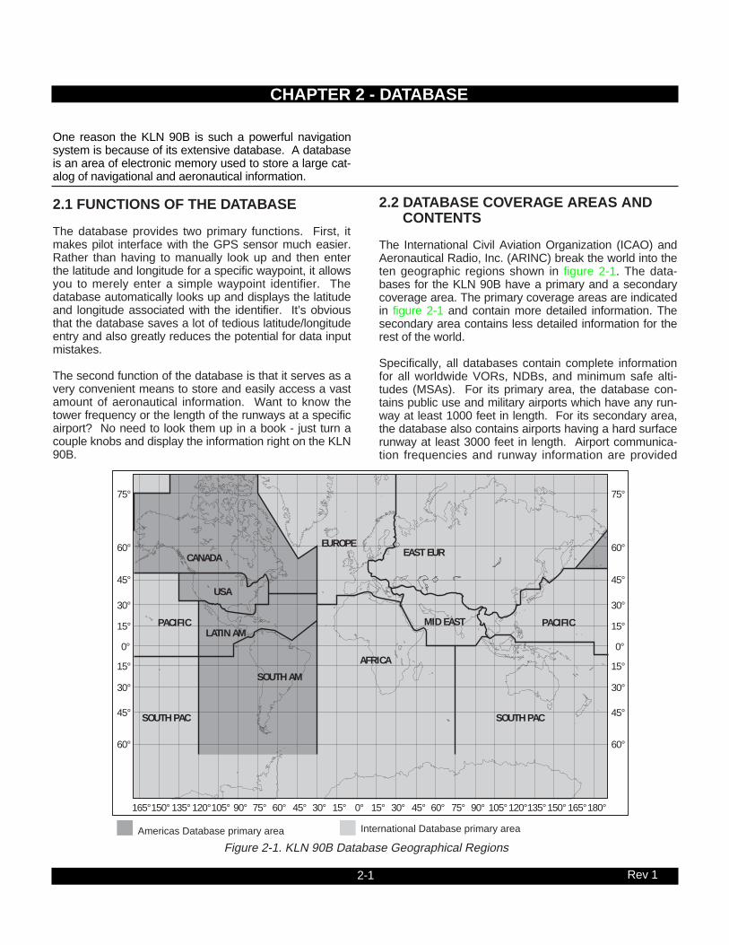
2.2 DATABASE COVERAGE AREAS AND CONTENTS
The International Civil Aviation Organization (ICAO) andAeronautical Radio, Inc. (ARINC) break the world into theten geographic regions shown in figure 2-1. The data-bases for the KLN 90B have a primary and a secondarycoverage area. The primary coverage areas are indicatedin figure 2-1 and contain more detailed information. Thesecondary area contains less detailed information for therest of the world.
Specifically, all databases contain complete informationfor all worldwide VORs, NDBs, and minimum safe alti-tudes (MSAs). For its primary area, the database con-tains public use and military airports which have any run-way at least 1000 feet in length. For its secondary area,the database also contains airports having a hard surfacerunway at least 3000 feet in length. Airport communica-tion frequencies and runway information are provided
CHAPTER 2 - DATABASE
CANADA
USA
LATIN AMPACIFIC
SOUTH PAC
SOUTH AM
EUROPEEAST EUR
MID EAST
AFRICA
SOUTH PAC
PACIFIC
75°
60°
45°
30°
15°
0°
15°
30°
45°
60°
75°
60°
45°
30°
15°
0°
15°
30°
45°
60°
165°150° 135° 120°105° 90° 75° 60° 45° 30° 15° 0° 15° 30° 45° 60° 75° 90° 105°120°135°150° 165°180°
International Database primary areaAmericas Database primary area
Figure 2-1. KLN 90B Database Geographical Regions

2-2 Rev 1
only for airports in the primary area of the database.Intersections, air route traffic control center data, flightservice station frequencies, and special use airspace arealso provided only for the primary area.
The following is a list of the KLN 90B database contents:
*AIRPORTS• Identifier• Name• City, State or Country• Type (public or military)• Latitude and Longitude• Elevation• Approach indicator for precision, non-precision or no
instrument approach at airport• Radar approach/departure environment indicator• Whether airport underlies CL B, TRSA, CL C, CTA, or
TMA• Time relative to UTC (Zulu)
• Communication frequencies (VHF and HF):ATIS Clearance delivery Tower Ground control Unicom Multicom Approach (IFR) Departure (IFR)Class B, Class C, TRSA, CTA, TMA (VFR) Center (when used for approach) Arrival RadarDirectorRadioAWOS (automatic weather observing station)AAS (aeronautical advisory service)ATF (Aerodrome traffic frequency)CTAF (common traffic advisory frequency)MF (mandatory frequency)Ramp controlPCL (pilot-controlled lights)
• Runway data (designation, length, surface, lighting, traffic pattern direction)
• Airport Services (fuel, oxygen, customs, indicator for presence of a landing fee)
• Airport Comments (user may manually enter remarks of up to 33 characters at any 100 airports in database)
VORs• Identifier• Name• Frequency• DME indicator• Class (high altitude, low altitude, terminal, undefined)• Latitude and Longitude• Magnetic variation
NDBs• Identifier• Name• Frequency• Latitude and Longitude
(Note - Outer Compass Locators are stored asIntersections)
*INTERSECTIONS (low altitude, high altitude, SID/STAR,approach, and outer markers)
• Identifier• Latitude and Longitude
*SID/STAR/Approach Procedures• All compatible pilot-nav SID/STAR procedures• Non-precision approaches (except localizer, LDA
(Localizer Directional Aid), SDF (Simplified Directional Facility)) approved for overlay use. Includes all public GPS only approaches.
MISCELLANEOUS• *Air Route Traffic Control Center (ARTCCs and FIRs)
boundaries and frequencies (VHF and HF)• *Flight Service Stations (Location of points of
communication and associated frequencies - VHF and HF)
• Minimum Safe Altitudes • *Special Use Airspace boundaries (Prohibited,
Restricted, Warning, Alert, MOA, Class B, TRSA, Class C, CTA, TMA)
250 USER DEFINED WAYPOINTS• Identifier• Latitude and Longitude• Additional data depending on how user defines
waypoint:User airports (elevation and surface of longest
runway)User VOR (frequency and magnetic variation)User NDB (frequency)
And you think your telephone directory has a lot of information!
* Items indicated with asterisk are included in the primarydatabase coverage area, but not in secondary coveragearea. The exception is that airports in primary coveragearea include those public and military bases having a run-way at least 1000 feet in length. Airports in secondarycoverage area are those having a hard surface runway atleast 3000 feet in length.

2-3 Rev 1
2.3 USE OF ICAO IDENTIFIERS
Waypoints are stored in the KLN 90B database almostexclusively by their ICAO identifiers. ICAO is an interna-tionally accepted reference for the data. In almost allcases the proper ICAO identifiers may be taken directlyfrom Jeppesen Sanderson or government aeronauticalcharts. For example, Dallas and Los Angeles VORs havethe familiar ICAO identifiers DFW and LAX, respectively.
Please note that one area of potential confusion is airportidentifiers in the Continental United States, Alaska, andCanada. Many airport identifiers in the database havefour letters beginning with a prefix letter that correspondsto the geographic area in which it is located. The prefixletter for the Continental United States is “K”. Thus, theidentifier for Dallas/Fort Worth International airport isKDFW, not DFW. This distinguishes the airport identifierfrom the VOR identifier. Likewise, the identifier for LosAngeles International airport is KLAX while the VOR iden-tifier is LAX. The prefix letter for Alaska is “P” and forCanada is “C”.
NOTE: There are several exceptions in Alaska. In manycases, airports with three letter identifiers receive theprefix “P”, but there are many that don’t. The most reliablemethod of determining an Alaska airport identifier is tolook it up from the airport name or city. See section 3.7.4,“Selecting Waypoints by Name or CIty”.
Not all airport identifiers receive the prefix letter. Airportidentifiers which are combinations of letters and numbersdo not receive the prefix letter. Examples of airport identi-fiers not using the prefix are 3C2, 7TX6, and M33.
So remember, if you are entering or looking for anairport identifier that is all letters (no numbers) then itwill begin with a “K” prefix in the Continental U.S., a“P” in Alaska, or a “C” in Canada. If there are num-bers in the identifier then a prefix is not used. Forother areas of the world the airport identifier stored inthe KLN 90B database is identical to how it ischarted.
2.4 UPDATING THE DATABASE
The information stored in the database would eventuallybecome obsolete if there wasn’t some means to update it.For example, navaids can move or change frequency,new runways can be added to an airport, communicationfrequencies can change, and on and on.
The database is housed in a cartridge which plugsdirectly into the back of the KLN 90B. It is designed sothat there are two ways for the user to easily keep thedatabase current. The first is to electronically update thedatabase by means of 3.5” diskettes supplied byAlliedSignal and a laptop computer. This method doesnot involve removing the KLN 90B from the aircraft’sinstrument panel. A jack, usually mounted in the aircraft’sinstrument panel, provides a means of interfacing theKLN 90B with the computer via an interface cable. Thediskettes are not returned to AlliedSignal.
The second method of database update is to remove theold cartridge and insert a current cartridge. This methodinvolves returning the old cartridge to AlliedSignal.
Every 28 days, AlliedSignal receives new NavData™information from Jeppesen Sanderson. This informationis processed and downloaded onto both diskettes anddatabase cartridges. AlliedSignal makes these two typesof update services available to you in a choice of severalsubscription or random update programs. See section 2.7of this manual for details on these programs.
Regardless of whether the computer method or the car-tridge exchange method of database updating is used,AlliedSignal sends the update so that it arrives prior to thenext effective date. The new update may be installed anytime prior to the effective date and the KLN 90B will usethe previous data up to the effective date and automati-cally begin using the new data on the effective date.
In order to get maximum utilization from the KLN 90B,AlliedSignal highly encourages you to update the data-base on a frequent basis, if not every 28 days. It is also amatter of safety to not fly with out of date information.
WARNING: The accuracy of the database informa-tion is only assured if it is used before the end of theeffectivity period. Use of out of date database infor-mation is done entirely at the user’s own risk.

2-4 Rev 1
2.4.1 Computer Updating Of The Database
Update information is sent to you on several 3.5” disks.In order to use this update method you must have accessto an IBM compatible computer having a disk drive capa-ble of using and booting (loading) from 3.5” 1.44megabyte high density disks. This computer also needsto have an available COM 1 or COM 2 serial port. Inaddition, an optional PC Interface kit must be used.Included in the kit are a data loader jack (wired to theKLN 90B and usually installed in the aircraft’s instrumentpanel) and an interface cable that plugs into both thecomputer and into the data loader jack.
CAUTION: The database must be updated only whilethe aircraft is on the ground. The KLN 90B does notperform any navigation functions while the databaseis being updated. Since a database update takesapproximately 10 minutes it is a good idea to turn offall electrical equipment on the aircraft except for theKLN 90B to avoid running down the aircraft battery.
NOTE: The disks sent to you can only be used to updateone KLN 90B, although they can update this specific unitnumerous times. The first time the disks are used in anupdate operation, a unique identification code from theKLN 90B being used is uploaded to the disks. Thesedisks may be used in this specific KLN 90B an unlimitednumber of times which could be required if you switchback and forth between the North American andInternational data bases during one update cycle. Thesedisks may not, however, be used to update other KLN90Bs. This update protection ensures that JeppesenSanderson is properly compensated for the use of theirNavData™.
Follow these steps to update the KLN 90B:
1. Plug the 9 pin female connector end of the interfacecable into a COM serial port of the computer. If the com-puter has COM 1 and COM 2 serial ports, either may beused. Some computers use a 9 pin COM serial port con-nector while other computers use a 25 pin connector. Ifthe computer being used has a 9 pin connector, the inter-face cable connector will plug directly into the computer’s9 pin connector. If the computer’s COM serial port uses a25 pin connector, use the 25 pin to 9 pin adapter includedin the PC interface kit to adapt the interface cable’s con-nector to the computer’s connector.
2. Plug the other end of the interface cable (4 conductormale plug) into the data loader jack that is mounted in theaircraft.

2-5 Rev 1
3. Turn on the computer being used for the databaseupdate. Insert Disk 1 into the computer’s disk drive.There can be either 2 or 3 disks used for the update sobe sure the label on the outside of the disk says “Disk 1 of2” or “Disk 1 of 3”. The program on the disk will automati-cally “boot” (load) and the computer screen will display“Ready” when the computer is ready to continue with thedatabase update operation.
4. Turn on the KLN 90B. Press E as required toapprove the Self Test and Database pages. Use the leftouter knob to select the Setup (SET) type pages and theleft inner knob to select the SET 0 page (figure 2-2).
5. Press the left C. UPDATE PUBLISHED DB willnow be displayed as in figure 2-3.
6. Press E. The database region and the expirationdate of the database presently loaded in the KLN 90B isdisplayed (figure 2-4). If the database is out of date theword EXPIRES changes to EXPIRED.
7. Press E to acknowledge the information on thispage and to continue the update procedure. The esti-mated load time in minutes is now displayed (figure 2-5).
NOTE: In steps 5, 6, and 7, repeated presses of @ willterminate the update process and bring the display backto the original SET 0 page shown in figure 2-2.
U P D A T E D A T A B A S E O N G R O U N D O N L Y SET 0
U P D A T E D A T A B A S E UPDATE PUBLISHED DB CRSR ent
U P D A T E N AMERICAN DATA BASE EXPIRES 17 AUG 94 U P D A T E ? CRSR ent
U P D A T E D A T A B A S E E S T . L O A D T I M E : 10 MIN A P P R O V E ? CRSR ent
Figure 2-2
Figure 2-3
Figure 2-4
Figure 2-5

2-6 Rev 1
8. Press E to acknowledge the estimated load timeand begin erasing the existing database. The unit willnow display ERASING DATA BASE (figure 2-6). Afterthe database has been erased, loading of the new databegins automatically. As the new data is being loaded,the percentage of transfer is displayed (figure 2-7).
9. Monitor the computer screen. When the first disk iscomplete the computer screen will display “Insert Disk 2then press any key to continue.” Disk 1 should now beremoved from the disk drive and disk 2 should beinserted. Press any key on the computer. The load oper-ation will continue. If there are 3 disks the computerscreen will prompt when to use disk 3.
10. The KLN 90B will indicate when the database updateis complete as shown in figure 2-8. The computer screenwill display the new database expiration date. You mayeither turn the KLN 90B off at this point or press E torestart the KLN 90B.
11. Remove the interface cable. Remove the disk fromthe computer. Turn off the computer.
The chances are small of having difficulty updating thedatabase but if you have a problem:
First check that the interface cable is properly connectedand that the computer is turned on. If there is a problemwith the connection or the computer the KLN 90B will dis-play LOADER NOT READY. When the problem is cor-rected this prompt is removed and the update operationcan continue from where it left off.
If the wrong disk is inserted the computer screen will dis-play “Incorrect Disk - please insert disk __.”, where thenumber 2 or 3 is inserted in the blank.
If an internal test fails after the data has been loaded, theKLN 90B will display CHECKSUM ERROR, DATA BASEINVALID, ACKNOWLEDGE?. Press E to acknowl-edge. The KLN 90B will then display RETRY and EXIT.Use the left outer knob to position the cursor over thedesired choice and press E.
There are other error messages that may be displayed. Ifyou have a problem that you can’t resolve, write downany error messages to aid your Bendix/King ServiceCenter in identifying the problem.
U P D A T E D A T A B A S E E R A S I N G D A T A B A S E SET 0
Figure 2-6
U P D A T E D A T A B A S E 14 PERCENT COMPLETE SET 0
Figure 2-7
U P D A T E D A T A B A S E UPDATE PUBLISHED DB COMPLETED ACKNOWLEDGE? CRSR ent
Figure 2-8

2-7 Rev 1
1. Insert the KLN 90B insertion/removal tool (suppliedwith unit) in the small hole located on the right side of thefront of the unit (figure 2-9). A standard 3/32 inch Allenwrench may also be used.
2. Turn the tool counterclockwise until the locking mech-anism becomes loose and then continue turning counter-clockwise until it just barely begins to become snug. Donot turn so far counterclockwise that the mechanismstarts to bind and can no longer be turned.
3. The KLN 90B should now be loose from the rack.Pull the unit out of the rack by pulling on the sides of theradio’s front panel. DO NOT REMOVE BY PULLING ONTHE KNOBS.
4. Remove the old database cartridge by pulling itstraight out the back of the KLN 90B (figure 2-10).
5. Remove the new database cartridge from its shippingcontainer. Note that the label on the cartridge indicates
PUSHON
APTVORNDBINT
SUPL
ı
MSG
CLRENT
D
BRT
NAVD/T
ACTVREFCTP.
KLN 90B TSO
GPS
FRONT LUG UPAND BACK LUG DOWN
CALCSTATSETUPOTHER
NAVFPL
MODETRIP
CRSR
CRSR
PULLSCAN
ALT
Figure 2-9
2.4.2 Cartridge Exchange Updating of the DatabaseTo exchange the KLN 90B cartridge it is necessary toremove the KLN 90B from the aircraft’s instrument panel.The KLN 90B and the mounting rack have been designedto provide for easy removal. Follow these steps to updatethe database cartridge.
INSERT TO HERENorth
Americ
an
P/N: 0
71-1469-00
AIRAC N
o. 8811
Document: 723-8088-11
Figure 2-10

2-8 Rev 1
which side is up and which end to insert into the KLN90B. Insert the new cartridge into the back of the unit.When the cartridge is properly inserted, the “Insert ToHere” marking on the label can just be seen protrudingfrom the rear of the KLN 90B (figure 2-11).
6. Make sure that the front lug of the locking mechanismis in the up position (figure 2-9). Insert the KLN 90Bback in the rack as far as it will go.
7. Re-insert the insertion/removal tool. Turn the toolclockwise until snug. The KLN 90B should now be lockedback into the mounting rack. Pull gently on the frontpanel to verify that the unit is indeed locked into its rack.
8. The container which was used to ship the new car-tridge to you is used to return the old cartridge back toAlliedSignal. A return shipping label is included in thecontainer. Remove the backing from the label and placeit in the address position of the shipping container.
9. Insert the old cartridge into the container. Peel off theprotective backing from the adhesive on the end flap ofthe container. Press the flap against the adhesive to sealthe container.
10. Please return the old cartridge promptly by mailingimmediately at any mailbox. No postage is required ifmailed from within the U.S. Users will be billed for car-tridges not returned and no additional cartridges will besent until either the old cartridge or payment for the oldcartridge is received.
2.5 USER DEFINED DATABASE
In addition to the published database of airports, VORs,NDBs, and intersections stored in the cartridge, you maycreate up to 250 other waypoints. These waypoints maybe designated by you to be one of the four waypoint typesabove or as a waypoint not falling into one of these types.In the latter case the waypoint is called a Supplementalwaypoint. Section 5.4 describes how you may create auser-defined waypoint.
2.6 INTERNAL MEMORY BACKUP BATTERY
The KLN 90B contains an internal lithium battery that isused to “keep-alive” the user-defined database as well asflight plans. This battery has a typical life of three to fiveyears. It is highly recommended that the battery bereplaced every three years at an authorized Bendix/KingService Center.
Figure 2-11
North American
P/N: 071-1469-00
AIRAC No. 8811
Document: 723-8088-11
INSERT TO HERE
2.7 DATABASE UPDATE SERVICE OPTIONS
The following tear-out pages can be used for ordering theNorth American and International database update ser-vices from AlliedSignal. The forms may be mailed orfaxed for your convenience.

Name:
Company:
Address:
City:
State: Zip Code:
Country:
Telephone: ( )
FAX: ( )
Aircraft Make:
Aircraft Model: ______
Please set up the service under:
MasterCard/VISA
Method of Payment
Check/Money order enclosed
Wire Transfer:Chase Manhattan Bank, NYAcct #910-2-538734
Tax may apply in some states.See pricing sheet.
Number
Expires
Signature
AlliedSignal GAA offers several update ser-vice options to suit your requirements.Please select the service desired, then fillout and mail this order form. Credit cardorders may be faxed.
Updates from the Internet can be obtaineddirectly by logging onto the AlliedSignalInternet site and following the instructions
provided, or by calling the telephone num-ber below to set up an account.
Note: Updates are current for 28 daysafter effective date on diskette. If youselect any service other than the complete13-time service, your KLN 90B will beginalerting you after 28 days that your database is out of date.
Send to:
AlliedSignal CASData Base Update ServiceMail Drop #66400 N. Rogers RoadOlathe KS 66062-1212Telephone: (913) 768-3020FAX: (913) 768-3904
Check One:
Complete Update Service .Provides 13 updates–one every 28days for one year.
Six-time Update Service .Provides six updates–one every 56days for one year.
Four-time Update Service .Provides four updates–one duringeach quarter for one year.
Single Update . Provides oneupdate upon receipt of order.
Check Requested Data Base:
Americas Data Base
International Data Base
Check One:
Database Card Format(available in U.S./Canada only)
Diskette Format(Laptop Computer Required. Seesection 2 of KLN 90B Pilot’s Guidefor details.)
KLN 90B Data Base Update Service Order FormConsult Pricing Sheet (006-08794-0001) for Service Prices
A

BUSINESS REPLY MAILFIRST-CLASS MAIL PERMIT NO. 121 OLATHE, KANSAS
POSTAGE WILL BE PAID BY ADDRESSEE
Fold here
NO POSTAGENECESSARY
IF MAILEDIN THE
UNITED STATES
ALLIEDSIGNAL COMMERCIAL AVIONICS SYSTEMSM D 66400 NORTH ROGERS ROADOLATHE KS 66062-9987
Tape here
3-1 Rev 1
This is the first of three chapters specifically dealing withoperating the KLN 90B. In this chapter you will learn thebasic operation of the front panel controls and then how
to perform Direct To navigation (navigating from your pre-sent position direct to your desired location).
CHAPTER 3 - LEVEL 1 OPERATION
74°
60°
45°
30°
15°
0°
15°
30°
45°
60°
74°
60°
45°
30°
15°
0°
15°
30°
45°
60°
Figure 3-1 KLN 90B Navigation Coverage Area
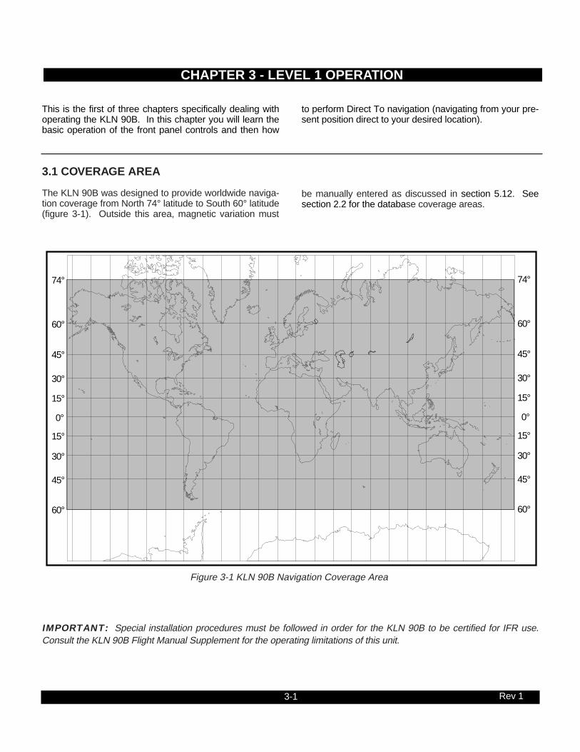
3.1 COVERAGE AREA
The KLN 90B was designed to provide worldwide naviga-tion coverage from North 74° latitude to South 60° latitude(figure 3-1). Outside this area, magnetic variation must
be manually entered as discussed in section 5.12. Seesection 2.2 for the database coverage areas.
IMPORTANT: Special installation procedures must be followed in order for the KLN 90B to be certified for IFR use.Consult the KLN 90B Flight Manual Supplement for the operating limitations of this unit.

CRSR
MSG D CLR ENT
KLN 90B TSOGPSı
CRSR
PUSHON
BRT
APTVORNDBINT
SUPL
NAVD/T
ACTVREFCTR
CALCSTAT
SETUPOTHER
NAVFPL
MODETRIP
PULLSCAN
LEFT OUTER
MESSAGE
DIRECT TO
CLEAR
ENTER
RIGHTOUTER
LEFT INNER RIGHTINNER
LEFT CURSOR POWER/BRIGHTNESS
RIGHTCURSOR $=KOSH |=KOSH
+++++Ê+++++|WITTMANDIS 683nm|GS 193kt|ETE 3:34|N 43^59.06'BRG 303^|W 88^33.42'NAV 1|enr-leg |APT 1
ALT
ALTITUDE
KLN 90B CONTROLS
Figure 3-2

3-3 Rev 1
3.2 TURN-ON AND SELF TEST
Enough of the preliminaries. Let’s get started into actu-ally turning the KLN 90B on and using it! Figure 3-2 willfold out and allow you to use it as a reference as you readthis chapter, especially if you don’t have a KLN 90Bimmediately at hand. The steps below take a lot of wordsto explain, but you will find that in actual use you willaccomplish these steps in just a few moments.
NOTE: When power is applied to the KLN 90B it always“wakes up” in the Enroute-Leg mode. Only the Enroute-Leg mode is described in this chapter. In this mode theKLN 90B performs great circle navigation (the shortestdistance between two points located on the earth’s sur-face). The course deviation output displayed on the unit’sinternal course deviation indicator (CDI) and provided toan external HSI or CDI is five nautical miles left and right,full scale sensitivity. The other modes of the unit aredescribed in section 5.9 and in chapter 6.
1. Turn-on the KLN 90B by pressing the power/bright-ness knob to the “in” position. The power/brightnessknob is located on the upper right side of the unit. Ittakes just a few seconds for the screen to warm up.
2. The Turn-On page will be displayed for a few sec-onds (figure 3-3). During this time the KLN 90B per-forms an extensive internal test. The ORS(Operational Revision Status) level number in theupper right corner of the display should match theORS level indicated on the first page of this Pilot’sGuide (page before Table of Contents). If desired,you may program four lines of personalized informa-tion which is displayed each time the Turn-On page isin view. The procedure for doing this is described insection 5.7.
When the internal test is complete, the Turn-On pagewill automatically be replaced by the Self Test page(figure 3-4). Note: if the KLN 90B is operating in thetake-home mode, the Take-Home Warning page (fig-ure 3-5) is displayed first and must be acknowledgedby pressing E. See section 5.14 for more informa-tion on the Take-Home mode.
3. Adjust the display brightness to the desired level byrotating the power/brightness knob. Clockwise rota-tion increases brightness and counterclockwise rota-tion decreases brightness.
4. Verify that the data displayed on the left side of theSelf Test page is the same as is being displayed onthe appropriate equipment in the aircraft which isinterfaced to the KLN 90B. If the KLN 90B is not con-nected to any other equipment in the aircraft, youmay skip to step 5.
GPS ORS 20 c1994 ALLIEDSIGNAL INC SELF TEST IN PROGRESS
DIS 34.5NM|DATE/TIME +++++j+‚⁄++| 31 JUL 94 OBS IN 242^|08:10:03CST OUT 315^|ALT 1100ft RMI 130^|BARO:29.92" ANNUN ON| APPROVE? enr-leg CRSR
4
WARNING: SYSTEM IS IN TAKE- HOME MODE: DO NOT USE FOR NAVIGATION ACKNOWLEDGE? enr-leg ent
Figure 3-3
Figure 3-4
Figure 3-5

3-4 Rev 1
The distance field (DIS) always displays 34.5 NM(nautical miles). If the KLN 90B is interfaced to acompatible indicator that displays DME distance, theindicator should be displaying 34.5 nautical miles.
If the KLN 90B is interfaced with a mechanical NAVindicator such as an HSI or a course deviation indica-tor (CDI), the D-bar (deviation bar) should be indicat-ing a half scale deviation to the right. In some EFISinstallations the D-bar may be deflected one third offull scale. This is due to the different CDI scale factorsthat are used. The TO/FROM indicator should beshowing FROM.
If the KLN 90B is interfaced with a NAV indicatorsuch that the KLN 90B can "read" the selectedcourse from the NAV indicator, then the OBS IN fieldshould display the same course as on the NAV indi-cator.
The OBS OUT field always displays 315 degrees andis only applicable when the KLN 90B is interfacedwith an HSI which has a driven course pointer capa-ble of being driven by the KLN 90B. This type of HSIis normally found in jets and turboprops. If this typeof NAV indicator is interfaced to the KLN 90B, thecourse pointer on the NAV indicator should be drivento 315 degrees and both the OBS IN and OBS OUTfields should be displaying 315 degrees.
The RMI field always displays 130 degrees. If theKLN 90B is connected to a compatible RMI in the air-craft, the RMI should indicate a bearing to the stationof 130 degrees.
If any of the above checks fail, do not use the associ-ated equipment with the KLN 90B.
5. If the KLN 90B has passed the internal self test, thebottom left side of the Self Test page will displayANNUN ON to indicate that the external annuncia-tors, if installed, should all be illuminated. If instead,a flashing TEST FAIL is displayed, recycle power tothe KLN 90B. If the Self Test page still displaysTEST FAIL, the KLN 90B requires repair and shouldnot be used for navigation.

3-5 Rev 1
The KLN 90B needs to have the correct time, date,and position to be able to determine which satellitesshould be in view. This information is stored in thebattery backed memory of the KLN 90B so it is notnormally required to update it. If the KLN 90B has thecorrect time, date, and position, then the time to firstfix will usually be just a couple of minutes or less. Ifthis information is not correct, then the KLN 90B willstart to look for any satellites. Eventually, the KLN90B will find enough satellites to determine the posi-tion of the aircraft. This process can take as long as12 minutes but will normally be around 6 minutes. It ispossible for you to update this information manuallywhich will allow the KLN 90B to reach a NAV readystatus much faster. To set the time and date followsteps 6 and 7. If the date and time are correct, oracquisition time is not important, then skip to step 8.
6. If the date is incorrect, rotate the right outer knobcounterclockwise until the cursor is over the entiredate field (figure 3-6). Rotate the right inner knobuntil the correct day of the month is displayed (figure3-7). Then, rotate the right outer knob one stepclockwise to place the flashing part of the cursor overthe month field (figure 3-8). Rotate the right innerknob to display the correct month (figure 3-9). Rotatethe right outer knob one step clockwise again anduse the right inner knob to select the first digit of thecorrect year (Figure 3-10). Next, rotate the right outerknob one more step clockwise and then use the rightinner knob to select the second digit of the year(figure 3-11). When the date is correct, press E.
7. If it is necessary to reset the time, use the right outerknob to position the cursor over the time zone field(figure 3-12). Use the right inner knob to select thedesired time zone (figure 3-13). The following are thetime zones which the KLN 90B is capable ofdisplaying:
UTC Coordinated Universal Time (Zulu)GST Greenland Standard Time (UTC - 3)GDT Greenland Daylight Time (UTC - 2)ATS Atlantic Standard Time (UTC - 4)ATD Atlantic Daylight Time (UTC - 3)EST Eastern Standard Time (UTC - 5)EDT Eastern Daylight Time (UTC - 4)CST Central Standard Time (UTC - 6)CDT Central Daylight Time (UTC - 5)MST Mountain Standard Time (UTC - 7)MDT Mountain Daylight Time (UTC - 6)PST Pacific Standard Time (UTC - 8)PDT Pacific Daylight Time (UTC - 7)AKS Alaska Standard Time (UTC - 9)AKD Alaska Daylight Time (UTC - 8)HAS Hawaii Standard Time (UTC - 10)HAD Hawaii Daylight Time (UTC - 9)SST Samoa Standard Time (UTC - 11)SDT Samoa Daylight Time (UTC - 10)
|DATE/TIME | 31 JUL 94 |08:10:14CST |ALT 1100ft |BARO:29.92" | CRSR
|DATE/TIME | 03 AUG 94 |08:10:14CST |ALT 1100ft |BARO:29.92" | APPROVE? CRSR
|DATE/TIME | 03 AUG 94 |14:10:55UTC |ALT 1100ft |BARO:29.92" | APPROVE? CRSR
|DATE/TIME | 03 AUG 94 |08:10:14CST |ALT 1100ft |BARO:29.92" | APPROVE? CRSR
|DATE/TIME | 03 AUG 9! |08:10:14CST |ALT 1100ft |BARO:29.92" | APPROVE? CRSR
|DATE/TIME | 03 AUG !! |08:10:14CST |ALT 1100ft |BARO:29.92" | APPROVE? CRSR
|DATE/TIME | 03 !!! !! |08:10:14CST |ALT 1100ft |BARO:29.92" | APPROVE? CRSR
|DATE/TIME | 03 !!! !! |08:10:14CST |ALT 1100ft |BARO:29.92" | APPROVE? CRSR
Figure 3-6 Figure 3-7
Figure 3-8 Figure 3-9
Figure 3-10 Figure 3-11
Figure 3-12 Figure 3-13

3-6 Rev 1
You will be able to change the time zone any time youdesire on several other pages, so don’t worry if you’re notsure which time zone to choose. UTC - CoordinatedUniversal Time (also called “Zulu”) is always a safechoice.
Once you have selected the desired time zone, turn theright outer knob one step counterclockwise to position thecursor over the entire time field (figure 3-14). Use the rightinner knob to select the correct hour (figure 3-15). Since24 hour time is used, be sure to add 12 if the time is after1:00 P.M.(2:30 P.M. becomes 14:30). Now turn the rightouter knob one step clockwise to position the flashing partof the cursor over the first minute’s position (figure 3-16).Turn the right inner knob to select the desired value.Turning the right outer knob one more step clockwise posi-tions the flashing part of the cursor over the secondminute’s position, and the right inner knob is now used tofinalize the time selection (figure 3-17). When the correcttime has been entered, press E to start the clock run-ning. Don’t worry that you can’t update the seconds. TheKLN 90B system time will automatically be corrected veryprecisely once a satellite is received.
8. Turn the right outer knob clockwise to position thecursor over the first two digits of the altimeter baro setfield if the cursor is not there already (figure 3-18).The last KLN 90B baro setting entered is displayed.If the correct altimeter setting is displayed skip to step10 after reading the following notes.
NOTE: The KLN 90B will use an altitude input from analtitude encoder or air data computer. Since the altitudefrom these devices is usually pressure altitude, an altime-ter baro correction is required to ensure maximum accu-racy. This altitude input is used for altitude related fea-tures of the KLN 90B. Therefore, it is important to keepthe altimeter baro setting updated on the Self Test pagewhen power is first applied to the KLN 90B and on theAltitude page each time a new baro correction is made tothe aircraft’s altimeter.
NOTE: The units of the altimeter baro setting may bechanged at a later time from inches to millibars on theSET 7 page.
NOTE: The altimeter baro set field will not be a cursorfield if the KLN 90B is interfaced to certain air data/altime-ter systems which update the baro set field when the air-craft’s altimeter baro setting is updated.
|DATE/TIME | 03 AUG 94 |14:10:59UTC |ALT 1100ft |BARO:29.92" | APPROVE? CRSR
|DATE/TIME | 03 AUG 94 |16:!!:08UTC |ALT 1100ft |BARO:29.92" | APPROVE? CRSR
|DATE/TIME | 03 AUG 94 |16:27:42UTC |ALT 1100ft |BARO:29.92" | APPROVE? CRSR
|DATE/TIME | 03 AUG 94 |16:27:08UTC |ALT 1100ft |BARO:29.92" | APPROVE? CRSR
|DATE/TIME | 03 AUG 94 |16:!!:08UTC |ALT 1100ft |BARO:29.92" | APPROVE? CRSR
Figure 3-14 Figure 3-15
Figure 3-16 Figure 3-17
Figure 3-18

3-7 Rev 1
9. To enter the correct baro setting, rotate the right innerknob to select the first two digits of the correct altime-ter setting (figure 3-19). Rotate the right outer knobone step clockwise to move the flashing cursor overthe third position. Use the right inner knob to selectthe correct number. Use the right outer and innerknobs to complete the baro setting (figure 3-20).Now press E.
10. With the correct altimeter setting entered, the altitudedisplayed on line 4 should be correct within 100 feet.
11. Turn the right outer knob clockwise to position thecursor over APPROVE? if it is not there already(figure 3-21). Press E to approve the Self Testpage. If the KLN 90B altitude alert audio is utilized inthe installation, five beeps should be heard when theSelf Test page is approved. The alert audio volumemay later be adjusted on the SET 9 page. (Note: Ifthe KLN 90B is installed for VFR only operation, aVFR only warning page is displayed after the selftest page has been approved (Figure 3-22). Thiswarning page must be acknowledged by pressingE .) If the KLN 90B is installed with an externalGPS CRS switch and the switch is in the OBSposit ion, then the OBS warning page wil l bedisplayed (figure 3-23). The GPS CRS switchshould be pushed so that the LEG mode isselected.)
12. The Database page will now be displayed with thecursor over ACKNOWLEDGE?. Line 1 indicates thecoverage area of the database being used. If thedatabase is current, line 3 will show the date whenthe database expires (figure 3-24).
If the database is out of date, line 3 shows the datethat it expired (figure 3-25). The KLN 90B will stillfunction with an out of date database; however, youmust exercise extreme caution and always verify thatthe database information is correct before using infor-mation from an out of date database.
Press E to acknowledge the information on theDatabase page.
WARNING: The accuracy of the database informationis assured only if the database is current. Operatorsusing an out of date database do so entirely at theirown risk.
|DATE/TIME | 03 AUG 94 |16:28:24UTC |ALT 1200ft |BARO:30.02" | APPROVE? CRSR
|DATE/TIME | 03 AUG 94 |16:27:53UTC |ALT 1100ft |BARO:30.92" | APPROVE? CRSR
|DATE/TIME | 03 AUG 94 |16:28:08UTC |ALT 1100ft |BARO:30.02" | APPROVE? CRSR
Figure 3-19 Figure 3-20
Figure 3-21
Figure 3-22
Figure 3-25
N AMERICAN DATA BASE EXPIRED 04 JUL 94 ALL DATA MUST BE CONFIRMED BEFORE USE ACKNOWLEDGE? enr-leg ent CRSR
FOR VFR USE ONLY ACKNOWLEDGE? ent CRSR
Figure 3-23
WARNING
SYSTEM IS IN OBS MODE PRESS GPS CRS BUTTON TO CHANGE TO LEG MODE enr:016
Figure 3-24
N AMERICAN DATA BASE EXPIRES 29 AUG 94 ACKNOWLEDGE? enr-leg ent CRSR
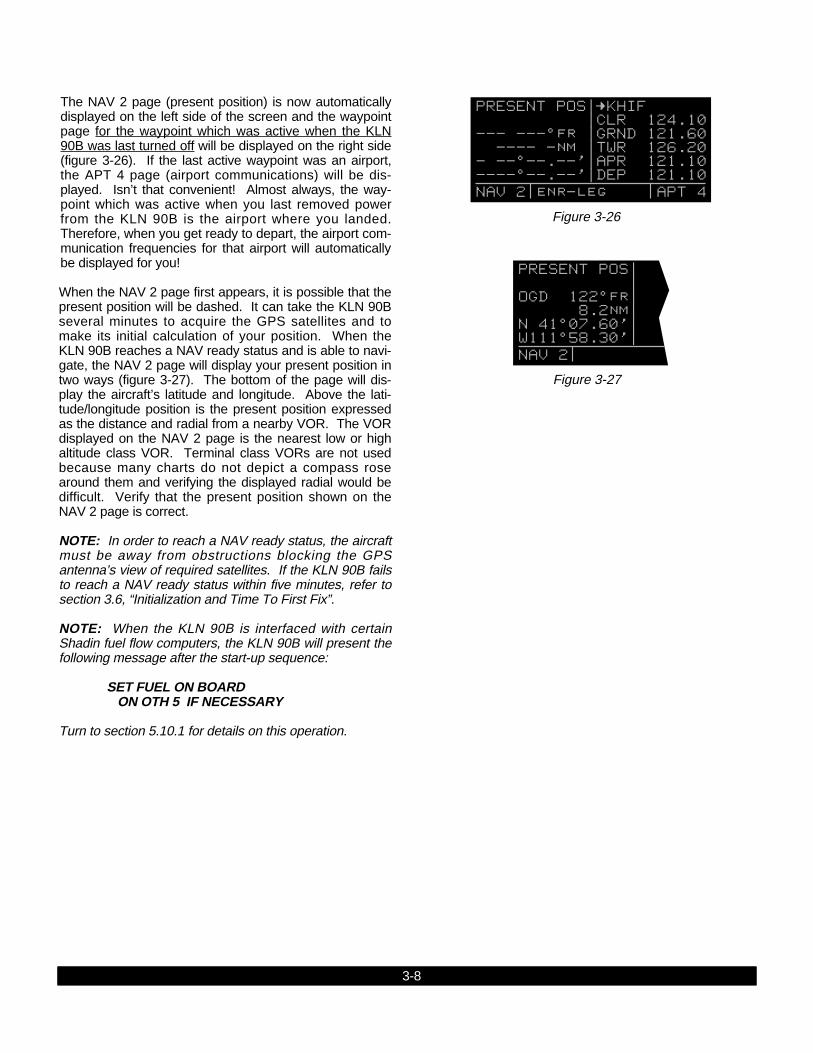
The NAV 2 page (present position) is now automaticallydisplayed on the left side of the screen and the waypointpage for the waypoint which was active when the KLN90B was last turned off will be displayed on the right side(figure 3-26). If the last active waypoint was an airport,the APT 4 page (airport communications) will be dis-played. Isn’t that convenient! Almost always, the way-point which was active when you last removed powerfrom the KLN 90B is the airport where you landed.Therefore, when you get ready to depart, the airport com-munication frequencies for that airport will automaticallybe displayed for you!
When the NAV 2 page first appears, it is possible that thepresent position will be dashed. It can take the KLN 90Bseveral minutes to acquire the GPS satellites and tomake its initial calculation of your position. When theKLN 90B reaches a NAV ready status and is able to navi-gate, the NAV 2 page will display your present position intwo ways (figure 3-27). The bottom of the page will dis-play the aircraft’s latitude and longitude. Above the lati-tude/longitude position is the present position expressedas the distance and radial from a nearby VOR. The VORdisplayed on the NAV 2 page is the nearest low or highaltitude class VOR. Terminal class VORs are not usedbecause many charts do not depict a compass rosearound them and verifying the displayed radial would bedifficult. Verify that the present position shown on theNAV 2 page is correct.
NOTE: In order to reach a NAV ready status, the aircraftmust be away from obstructions blocking the GPSantenna’s view of required satellites. If the KLN 90B failsto reach a NAV ready status within five minutes, refer tosection 3.6, “Initialization and Time To First Fix”.
NOTE: When the KLN 90B is interfaced with certainShadin fuel flow computers, the KLN 90B will present thefollowing message after the start-up sequence:
SET FUEL ON BOARDON OTH 5 IF NECESSARY
Turn to section 5.10.1 for details on this operation.
PRESENT POS| | OGD 122^fr| 8.2nm| N 41^07.60'| W111^58.30'| NAV 2
Figure 3-27
Figure 3-26
PRESENT POS|=KHIF |CLR 124.10 --- ---^fr |GRND 121.60 ---- -nm |TWR 126.20 - --^--.--'|APR 121.10 ----^--.--'|DEP 121.10 NAV 2 enr-leg APT 4
3-8
3-9 Rev 1
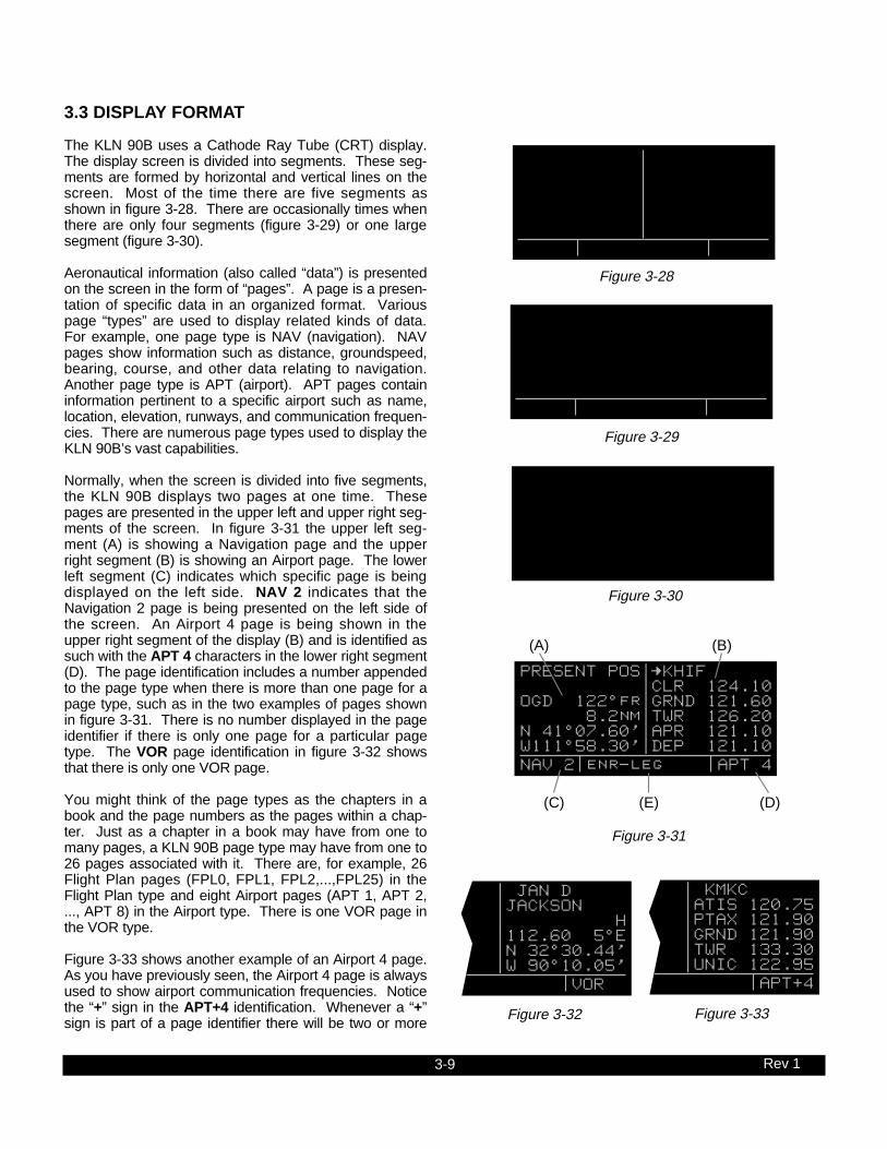
3.3 DISPLAY FORMAT
The KLN 90B uses a Cathode Ray Tube (CRT) display.The display screen is divided into segments. These seg-ments are formed by horizontal and vertical lines on thescreen. Most of the time there are five segments asshown in figure 3-28. There are occasionally times whenthere are only four segments (figure 3-29) or one largesegment (figure 3-30).
Aeronautical information (also called “data”) is presentedon the screen in the form of “pages”. A page is a presen-tation of specific data in an organized format. Variouspage “types” are used to display related kinds of data.For example, one page type is NAV (navigation). NAVpages show information such as distance, groundspeed,bearing, course, and other data relating to navigation.Another page type is APT (airport). APT pages containinformation pertinent to a specific airport such as name,location, elevation, runways, and communication frequen-cies. There are numerous page types used to display theKLN 90B’s vast capabilities.
Normally, when the screen is divided into five segments,the KLN 90B displays two pages at one time. Thesepages are presented in the upper left and upper right seg-ments of the screen. In figure 3-31 the upper left seg-ment (A) is showing a Navigation page and the upperright segment (B) is showing an Airport page. The lowerleft segment (C) indicates which specific page is beingdisplayed on the left side. NAV 2 indicates that theNavigation 2 page is being presented on the left side ofthe screen. An Airport 4 page is being shown in theupper right segment of the display (B) and is identified assuch with the APT 4 characters in the lower right segment(D). The page identification includes a number appendedto the page type when there is more than one page for apage type, such as in the two examples of pages shownin figure 3-31. There is no number displayed in the pageidentifier if there is only one page for a particular pagetype. The VOR page identification in figure 3-32 showsthat there is only one VOR page.
You might think of the page types as the chapters in abook and the page numbers as the pages within a chap-ter. Just as a chapter in a book may have from one tomany pages, a KLN 90B page type may have from one to26 pages associated with it. There are, for example, 26Flight Plan pages (FPL0, FPL1, FPL2,...,FPL25) in theFlight Plan type and eight Airport pages (APT 1, APT 2,..., APT 8) in the Airport type. There is one VOR page inthe VOR type.
Figure 3-33 shows another example of an Airport 4 page.As you have previously seen, the Airport 4 page is alwaysused to show airport communication frequencies. Noticethe “+” sign in the APT+4 identification. Whenever a “+”sign is part of a page identifier there will be two or more
| JAN D |JACKSON | H |112.60 5^E |N 32^30.44' |W 90^10.05' VOR
| KMKC |ATIS 120.75 |PTAX 121.90 |GRND 121.90 |TWR 133.30 |UNIC 122.95 APT[4
PRESENT POS|=KHIF |CLR 124.10 OGD 122^fr|GRND 121.60 8.2nm|TWR 126.20 N 41^07.60'|APR 121.10 W111^58.30'|DEP 121.10 NAV 2 enr-leg msg APT 4
(A) (B)
(C) (E) (D)
Figure 3-32 Figure 3-33
Figure 3-28
Figure 3-29
Figure 3-31
Figure 3-30
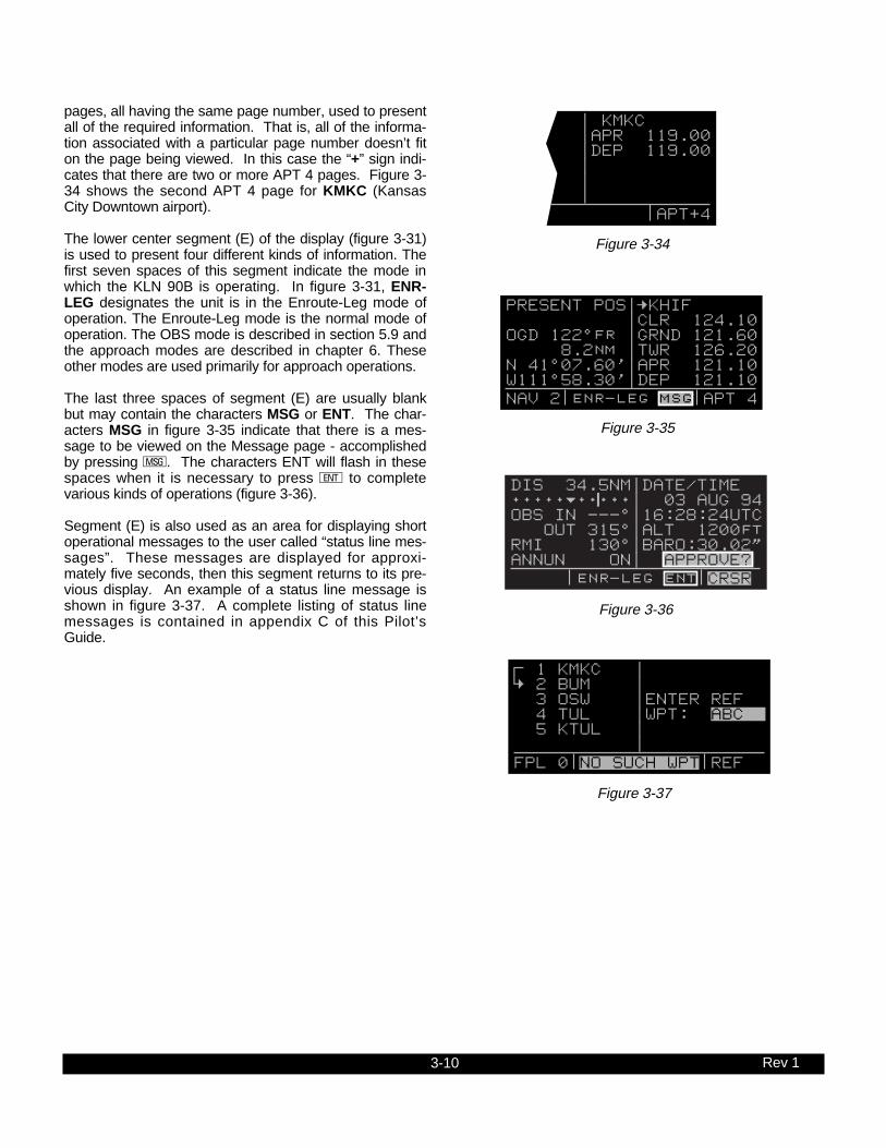
3-10 Rev 1
pages, all having the same page number, used to presentall of the required information. That is, all of the informa-tion associated with a particular page number doesn’t fiton the page being viewed. In this case the “+” sign indi-cates that there are two or more APT 4 pages. Figure 3-34 shows the second APT 4 page for KMKC (KansasCity Downtown airport).
The lower center segment (E) of the display (figure 3-31)is used to present four different kinds of information. Thefirst seven spaces of this segment indicate the mode inwhich the KLN 90B is operating. In figure 3-31, ENR-LEG designates the unit is in the Enroute-Leg mode ofoperation. The Enroute-Leg mode is the normal mode ofoperation. The OBS mode is described in section 5.9 andthe approach modes are described in chapter 6. Theseother modes are used primarily for approach operations.
The last three spaces of segment (E) are usually blankbut may contain the characters MSG or ENT. The char-acters MSG in figure 3-35 indicate that there is a mes-sage to be viewed on the Message page - accomplishedby pressing M. The characters ENT will flash in thesespaces when it is necessary to press E to completevarious kinds of operations (figure 3-36).
Segment (E) is also used as an area for displaying shortoperational messages to the user called “status line mes-sages”. These messages are displayed for approxi-mately five seconds, then this segment returns to its pre-vious display. An example of a status line message isshown in figure 3-37. A complete listing of status linemessages is contained in appendix C of this Pilot’sGuide.
| KMKC |APR 119.00 |DEP 119.00 | | | APT[4
PRESENT POS|=KHIF |CLR 124.10 OGD 122^fr |GRND 121.60 8.2nm |TWR 126.20 N 41^07.60'|APR 121.10 W111^58.30'|DEP 121.10 NAV 2 enr-leg msg APT 4
DIS 34.5NM|DATE/TIME+++++j+‚⁄++| 03 AUG 94OBS IN ---^|16:28:24UTC OUT 315^|ALT 1200ftRMI 130^|BARO:30.02"ANNUN ON| APPROVE? enr-leg ent CRSR
; 1 KMKC | < 2 BUM | 3 OSW |ENTER REF 4 TUL |WPT: ABC 5 KTUL | | FPL 0 NO SUCH WPT REF
Figure 3-34
Figure 3-35
Figure 3-36
Figure 3-37

3-11 Rev 1
1 KMKC | 2 BUM | 3 OSW | 4 TUL | 5 KTUL | | CRSR
Figure 3-38
3.4 BASIC OPERATION OF PANEL CONTROLS
Remember that figure 3-2 is on a fold-out page that youmay want to refer to as you read this chapter.
The KLN 90B has five knobs and seven buttons whichare used to perform all operations. In general, the twoconcentric knobs and the cursor button (C) located onthe left side of the unit are used to select pages and enterdata on the left side of the screen. Likewise, the two con-centric knobs and the cursor button on the right side ofthe unit are used to select pages and enter data on theright side of the screen.
The cursor is an area of inverse video (dark characters ona light background) on the screen. Many pages allow youto add, delete, or change data on the screen by firstpressing the appropriate C button (left C for left sideof screen and right C for right side) to turn the cursorfunction on and bring the cursor on the screen. Theappropriate knobs are then used to enter the data. Whena cursor is on the screen, the page name normally shownin the lower left and right segments is replaced with aCRSR annunciation in inverse video (figure 3-38). Thecursor is over the identifier TUL. Not all pages allow youto make data entry and therefore pressing the C but-ton while these pages are displayed will have no effect.
There are times when the cursor is flashing. Figure 3-36shows an example of how a white border is used in thisPilot’s Guide to depict a flashing cursor (overAPPROVE?). In addition, figure 3-36 shows an exampleof how a white border around normal text in this Pilot’sGuide is used to depict normal characters flashing. Theletters ENT are flashing but are not in inverse video.

3-12 Rev 1
3.4.1 Page SelectionIt’s now time for learning to select a desired page.
NOTE: The cursor function, which is controlled by the leftand right C (cursor) buttons, is not used in selectingpages and the C buttons should not be pressed at thistime. If CRSR is annunciated in the lower left or rightsegments of the display, press the left or right C button(as appropriate) to turn the cursor function off.
The left outer knob is rotated to select one of eight pagetypes for the left side of the screen. These eight pagetypes are the following:
Page Annunciation Knob Annunciation Page Name Page Numbers
TRI TRIP Trip Planning 0-6MOD MODE Mode 1-2FPL FPL Flight Plan 0-25NAV NAV Navigation 1-5CAL CALC Calculator 1-7STA STAT Status 1-5SET SETUP Setup 0-9OTH OTHER Other 1-4*
*up to 10 with fuel management system and air data interfaces
Remember that the page type for the left side is alwaysannunciated in the lower left segment of the screen. Thefirst three letters of the page type are always used forannunciation on the screen TRI for TRIP, MOD for Mode,SET for SETUP, etc. Rotating the left outer knob clock-wise selects the page type in the top-to-bottom ordershown above. Rotating the left outer knob counterclock-wise selects the page type in the opposite order. Thepage type selection wraps around from OTHER to TRIP;that is, the knob has no mechanical stops.
Once you have selected the desired page type using theleft outer knob, you may select the page number by rotat-ing the left inner knob. Let’s use an example to makesure you understand. You are presently viewing the NAV2 page on the left page. You wish to view the CAL 5page. Rotating the left outer knob one step clockwise willdisplay the CAL page that you last viewed-we’ll say theCalculator 1 page. Turning the left inner knob four stepsclockwise or three steps counterclockwise will bring youto the CAL 5 page. Got it?

3-13 Rev 1
Page Annunciation Knob Annunciation Page Name Page Numbers
CTR CTR Center Wpt. 1-2REF REF Reference Wpt. NoneACT ACTV Active Wpt. **D/T D/T Distance/Time 1-4NAV NAV Navigation 1-5APT APT Airport Wpt. 1-8VOR VOR VOR Wpt. NoneNDB NDB NDB Wpt. NoneINT INT Intersection Wpt. NoneSUP SUPL Supplemental Wpt. None
**Varies with the type of waypoints in the active flight plan
The second difference from the left side is that the rightinner knob has both an “in” and an “out” position. Withthe knob pushed “in” it works exactly like the inner knobon the left side. Make sure the right inner knob is pushed“in” for now. Later in this chapter we’ll discuss how theright inner knob in the “out” position performs a waypointscan function.
NOTE: In this Pilot’s Guide the right smaller knob isassumed to be in the “in” position unless it specificallystates that the knob should be in the “out” position.Therefore, the words “rotate the right inner knob” mean toturn the right inner knob while the knob is in the “in” posi-tion.
You’ve probably already figured out that the right side ofthe unit operates in a similar manner to the left side.There are, however, a couple of differences. First, thepage types are different for the right side except for NAV.The Navigation pages are identical on both sides of thescreen. Just as on the left side, only the first three lettersof the page type are used for annunciation on the screen.The page types for the right side are the following:

3-14 Rev 1
3.4.2 Data EntryNow that you’ve learned how to select the desired page,you’re ready to learn the means of entering data. It isnecessary to enter data, for example, in order to specify aDirect To waypoint of your choice. The general proce-dure for entering a waypoint identifier is described below.The Trip Planning 3 (TRI 3) page is shown in this exam-ple but the procedure is applicable to many other pages.You need not perform these steps now since they will bedescribed again shortly.
1. If the cursor is not positioned on the screen locationwhere you desire to enter the waypoint identifier (fig-ure 3-39), press C (left C for left page or right Cfor right page) to turn on the cursor function (figure 3-40).
2. If required, rotate the outer knob (left outer knob forleft page or right outer knob for right page) to positionthe cursor in the desired location (figure 3-41).
3. Rotate the appropriate inner knob to select the firstcharacter of the waypoint identifier (figure 3-42).
4. Turn the appropriate outer knob one step clockwise tomove the cursor to the second character position (fig-ure 3-43).
5. Rotate the inner knob to select the second character(figure 3-44).
6. Use the outer and inner knobs in this manner until thecomplete waypoint identifier is displayed (figure 3-45).Note that you may not have to enter the last charac-ters of the identifier because each time you enter acharacter, the KLN 90B offers you the first identifier inthe database beginning with the characters you haveentered.
7. If ENT is flashing in the lower middle segment of thedisplay, then press E. This will display a waypointpage on the right side of the screen for the waypointidentifier you just entered (figure 3-46).
8. Verify the waypoint information displayed, and thenpress E again to approve the waypoint page. Theright side will return to the page previously displayed(figure 3-47).
KLAX -KOAK | 293nm 305^| 180kt 1:38| FF: 00030.0| RES:00025.0| F REQ 73.9| TRI 3
KLAX -KOAK | 293nm 305^| 180kt 1:38| FF: 00030.0| RES:00025.0| F REQ 73.9| CRSR
KLAX -KOAK | 293nm 305^| 180kt 1:38| FF: 00030.0| RES:00025.0| F REQ 73.9| CRSR
KLAX -K | 293nm 305^| 180kt 1:38| FF: 00030.0| RES:00025.0| F REQ 73.9| CRSR
KLAX -K | 293nm 305^| 180kt 1:38| FF: 00030.0| RES:00025.0| F REQ 73.9| CRSR
KLAX -KR | 293nm 305^| 180kt 1:38| FF: 00030.0| RES:00025.0| F REQ 73.9| CRSR
KLAX -KRNO | $=KMYF 293nm 305^|+++++Ê+++++ 180kt 1:38|DIS 360nm FF: 00030.0|GS 180kt RES:00025.0|ETE 2:00 F REQ 73.9|BRG 253^ CRSR enr-leg ent NAV 1
KLAX -KRNO | KRNO 293nm 305^|RENO CANNON 180kt 1:38| INTL FF: 00030.0|CL C RES:00025.0|N 39^29.95' F REQ 73.9|W119^46.03' CRSR enr-leg ent APT 1
KLAX -KRNO | $=KMYF 340nm 334^|+++++Ê+++++ 180kt 1:53|DIS 360nm FF: 00030.0|GS 180kt RES:00025.0|ETE 2:00 F REQ 81.7|BRG 253^ CRSR enr-leg NAV 1
Figure 3-39 Figure 3-40
Figure 3-41 Figure 3-42
Figure 3-43 Figure 3-44
Figure 3-45
Figure 3-46
Figure 3-47

3-15 Rev 1
3.4.3 Alternative Waypoint Data Entry MethodThere is another method of data entry for waypointswhich you will sometimes find convenient. This methodapplies when there is a page on the left side of the screenwith the cursor over a field where a waypoint is enterable.You may fill the waypoint field on the left side by firstselecting the desired waypoint page on the right side (fig-ure 3-48). When E is pressed, the waypoint field on theleft will contain the flashing identifier of the waypoint thatis displayed on the right side (figure 3-49). To finalize thesection, E is pressed again (figure 3-50).
3.4.4 The Duplicate Waypoint PageThere are some waypoints in the database whose identi-fiers are not unique. That is, more than one waypoint hasthe same identifier. When a waypoint identifier has beenentered which is not unique to a single waypoint, aDuplicate Waypoint page appears on the left side (figure3-52). The Duplicate Waypoint page is used to selectwhich of the waypoints having the same identifier is actu-ally desired. The waypoint identifier is displayed on thetop left of the page. To the right of the identifier is thenumber of waypoints in the database having the identifier.Below the identifier is a list of the waypoint types (APT,VOR, NDB, INT, SUP) and the associated countrieswhich use the identifier. To see an example of aDuplicate Waypoint page perform the following steps:
1. Press D
2. Turn the left inner knob to select the letter “D” as awaypoint identifier (figure 3-51). “D” is the full identifier ofseveral waypoints in the KLN 90B database.
3. Press E. The Duplicate Waypoint page will be dis-played on the left side (figure 3-52). At the time of thiswriting, there were ten waypoints in the database havingthe identifier “D”. As in this example, if there are morethan four waypoints having the same identifier, only thefirst four are initially shown. The list includes an NDB inCanada, an NDB in Cuba, an NDB in the United States,and an NDB in Libya. The cursor will be over the firstwaypoint listed. They are listed with the waypoint closestto the aircraft’s present position displayed first and thewaypoint farthest from the aircraft displayed last. To viewthe rest, rotate the left outer knob clockwise. Doing sowill move the flashing cursor over waypoints two, three,and four and then will cause the waypoint list to “scroll” sothat the other waypoints in the list may be seen. Toselect the desired waypoint, move the cursor over theappropriate choice (figure 3-53).
4. Press E to view the waypoint page for the selectedwaypoint (figure 3-54).
5. Press E to approve the waypoint page.
P.POS-KLAX | KLAX 57nm 175^|LOS ANGELES 180kt 0:13| INTL FF: 00030.0|CL B RES:00025.0|N 33^56.55' F REQ 34.4|W118^24.43' CRSR enr-leg APT 1
D 11| TYPE AREA| 5 NDB ROM?| 6 NDB FIN?| 7 NDB CHN?| 8 NDB VMN?| CRSR
DIRECT TO: | D |BEIJING D | |FREQ 387 |N 40^04.00' |E116^34.50' CRSR enr-leg ent NDB
DIRECT TO: | | D | | | | CRSR
4
D 11| TYPE AREA| 1 NDB CAN?| 2 NDB CUB?| 3 NDB USA?| 4 NDB LBY?| CRSR
P.POS-KDEN | KLAX 701nm 055^|LOS ANGELES 180kt 3:54| INTL FF: 00030.0|CL B RES:00025.0|N 33^56.55' F REQ 142|W118^24.43' CRSR enr-leg APT 1
4
P.POS-KLAX | KLAX 701nm 055^|LOS ANGELES 180kt 3:54| INTL FF: 00030.0|CL B RES:00025.0|N 33^56.55' F REQ 142|W118^24.43' CRSR enr-leg ent APT 1
Figure 3-48
Figure 3-49
Figure 3-50
Figure 3-51 Figure 3-52
Figure 3-54
Figure 3-53

3-16 Rev 1
3.5 MESSAGE PAGE
Whenever the KLN 90B determines that there is a situa-tion that requires your attention, the MSG prompt beginsflashing in inverse video at the bottom of the display justto the right of the mode of operation (figure 3-55). Aremote message annunciator may also be installed in theaircraft instrument panel. You should view the messageat your earliest opportunity because the unit may be alert-ing you to some condition of immediate concern to itscondition or to your flight. To view the message, pressM. The MSG page, which takes the whole width of thedisplay, will appear and show the new message (figure 3-56). Appendix B of this Pilot’s Guide contains a listing ofall the Message page messages and their meanings. It ispossible that several messages are displayed at one timeon the Message page. The newest message appearsfirst and the rest in reverse chronological order.
After reading the message, press M again to return tothe pages which were previously in view. If all of themessages cannot be displayed on one Message page,repeated presses of M will show the other messagesbefore returning to the pages which were previously beingviewed. Whenever a message condition exists whichrequires a specific action by you, the message prompt willremain on but not flashing.
PRESENT POS|=KMKO |UNIC 122.80 OKM 086^fr|CTAF 122.80 24.4nm|PCL 122.80 N 35^39.78'|CTR 127.30 W 95^22.05'| NAV 2 enr-leg msg APT 4
Figure 3-55
INSIDE SPC USE AIRSPACE A-564 ALRT BELOW 2000ft enr-leg msg
Figure 3-56

3-17 Rev 1
3.6 INITIALIZATION AND TIME TO FIRST FIX
Since the KLN 90B stores its position and other requiredparameters in memory when power to the unit isremoved, it is seldom necessary to aid the unit in reach-ing a NAV ready condition. The time required from poweron until the KLN 90B determines its present position andis therefore ready to navigate is called “time to first fix.”The time to first fix is normally a few minutes or less. Inorder for the KLN 90B to reach a NAV ready condition, itis necessary to meet the following conditions:
1. The KLN 90B’s “almanac” data must be current.Almanac data is crude orbital information for all thesatellites and is used for initial acquisition when theKLN 90B is first turned on. This data is stored in theKLN 90B’s non-volatile memory and is considered cur-rent for up to six months. Each satellite sendsalmanac data for all satellites. Since the KLN 90Broutinely updates the almanac data during normaloperation, the almanac data will become out of dateonly if the KLN 90B hasn’t been used for the previoussix months or longer. Collecting new almanac datatakes place automatically if the data is more than sixmonths old. If the almanac data is out of date andneeds to be collected, the KLN 90B will take a fewminutes to acquire your present position (usuallyabout six (6) minutes, but not more than 12 minutes).The Self Test and Database pages should beapproved.
2. The aircraft must be located such that the GPSantenna has an unobstructed view of the sky so thatrequired satellite signals are not being blocked. Ifnecessary, position the aircraft away from hangars orother obstructions.
3. It is very helpful for the KLN 90B to have the correcttime, date and position to be able to determine whichsatellites should be in view. This information is storedin the battery backed memory of the KLN 90B so it isnot normally required to update it. If the KLN 90B hasthe correct time, date and position, then the time tofirst fix will usually be less than two (2) minutes. If thisinformation is not correct, then the KLN 90B will startto look for any satellites. Eventually, the KLN 90B willfind enough satellites to determine the position of theaircraft. This process can take as long as 12 minutes.It is possible for you to update this informationmanually which will allow the KLN 90B to reach a NAVready status much faster. To set the time and datefollow steps 6 and 7 in section 3.2, “Turn-On and Self-Test.” If it is necessary to update the position then usethe following steps. Remember, if acquisition time isnot important then it is not necessary to update thetime, date or position.

3-18 Rev 1
1. Select the Setup 1 page (SET 1) by first turning theleft outer knob to display a SET type page. Next, turnthe left inner knob until the SET 1 page is selected(figure 3-57).
2. Press the left C to bring the cursor on the page overthe WPT field (figure 3-58).
3. Use the left inner knob to enter the first character ofthe identifier for the airport where you are presentlylocated or the identifier of a navaid or other airportwhich is close to you. Remember, if you are enteringan airport identifier that is all letters (no numbers),then it will begin with a “K” prefix in the ContiguousU.S., a “P” in Alaska, or a “C” in Canada. If there arenumbers in the identifier then a prefix is not used.Outside the Contiguous U.S., Alaska, and Canada,use the airport identifiers as they are charted.
4. Rotate the left outer knob one step clockwise to movethe flashing portion of the cursor to the second posi-tion and then use the left inner knob to enter the sec-ond character of the identifier.
5. Complete entering the rest of the identifier using theleft knobs in the same manner as in step 4 (figure 3-59).
6. Press E to view the waypoint page on the right side.
7. Press E again to confirm the waypoint page.
NOTE: As an alternative, you can also enter the approxi-mate latitude and longitude of your present positiondirectly on the SET 1 page instead of entering a waypointidentifier.
8. Use the left outer knob to position the cursor overCONFIRM?, if it is not there already (figure 3-60).
9. Press E.
INIT POSN | WPT: | N 37^39.00'| W 97^25.97'| 0 KT 308^| | SET 1
Figure 3-57
INIT POSN | WPT: | N 37^39.00'| W 97^25.97'| 0 KT 308^| | SET 1
Figure 3-58
INIT POSN | WPT: KMKC | N 37^39.00'| W 97^25.97'| 0 KT 308^| | SET 1
Figure 3-59
INIT POSN | WPT: KMKC | N 39^07.40'| W 94^35.55'| 0 KT 308^| CONFIRM? | CRSR
Figure 3-60

3-19 Rev 1
NOTE: The groundspeed (KT) and heading ( °) fields arenot used for actual initialization in an aircraft. However, ifthe KLN 90B is in the take-home mode, entering agroundspeed will allow the KLN 90B to “fly” along theactive flight plan (or to a direct to waypoint) starting fromthe initialization waypoint. A heading may be entered inthe initial heading field while in the take-home mode if theone offered is not desired. If the take-home mode isused, remember to re-initialize the KLN 90B to the air-craft’s location before reinstalling it back in the aircraft.
10.Use the left knobs to select the NAV 2 page. Whenthe KLN 90B reaches the NAV ready status and istherefore able to navigate, the NAV 2 page will displaythe present position. Verify that the latitude and longi-tude or the VOR, radial, and distance display of pre-sent position are correct.

3-20 Rev 1
3.7 SELECTING WAYPOINTS
There are five types of waypoints: airports, VORs, NDBs,intersections, and supplemental. Waypoints in the pub-lished database (those in the cartridge) fall into one of thefirst four types. Remember that you can create up to 250of your own waypoints which you may designate as oneof the first four types or you may designate it as a supple-mental waypoint which simply means that it is a miscella-neous waypoint that doesn’t fit into one of the other cate-gories.
There are three methods you may use to select a specificwaypoint for viewing. You may enter the waypoint’s iden-tifier directly, you may scan through the waypoint identi-fiers in alphabetical order, or, you may enter the way-point’s name. If the waypoint is an airport, you may alsoselect it by entering the city where the airport is located.
3.7.1 Selecting Waypoints By IdentifierThe most direct way of selecting a specific waypoint is tosimply enter the waypoint’s identifier directly on theappropriate waypoint page type (APT, for example). Let’suse San Antonio International airport whose identifier isKSAT as an example to illustrate how this is done.
1. Rotate the right outer knob to select the airport typepages (APT). Rotate the right inner knob to select theAPT 1 page if it is not already in view (figure 3-61).(Actually, the airport identifier can be entered on anyof the eight Airport pages but we’ll use the APT 1since it displays the airport name.)
2. Press the right C to bring the cursor on the screenover the first character in the airport identifier (figure 3-62). The right inner knob should be pushed in the “in”position.
3. Turn the right inner knob to select a “K” (figure 3-63).You may turn the knob either clockwise or counter-clockwise, the letters and numbers wrap around with ablank character separating the “9” and the ”A”. Goahead and experiment a little bit.
4. Rotate the right outer knob one step clockwise to posi-tion the cursor over the second character in the airportidentifier (figure 3-64).
5. Use the right inner knob to select the second charac-ter, “S” (figure 3-65).
6. Use the right outer and right inner knobs in the samemanner as above to select the “A” and the “T” (figure3-66). You are now viewing the APT 1 page forKSAT.
7. Press the right C to remove the cursor from theright page. The APT 2, APT 3, APT 4, APT 5, APT 6,APT 7 and APT 8 pages may be viewed by rotatingthe right inner knob.
| B19 |BIDDEFORD |MUN | |N 43^27.84' |W 70^28.38' APT 1
| B19 |BIDDEFORD |MUN | |N 43^27.84' |W 70^28.38' CRSR
| K00 |HALL | | |N 32^30.97' |W 96^14.20' CRSR
| K00 |HALL | | |N 32^30.97' |W 96^14.20' CRSR
| KS01 |HOXIE- |SHERIDAN | |N 39^22.17' |W100^26.08' CRSR
| KSAT|SAN ANTONIO| INTL|CL C|N 29^32.02'|W 98^28.19' CRSR
Figure 3-61 Figure 3-62
Figure 3-63 Figure 3-64
Figure 3-65 Figure 3-66

3-21 Rev 1
Did you notice that as you entered the “K” in step 3 thatthe second and third characters also changed? That isbecause every time you enter a character (in this casethe “K”), the KLN 90B searches its database to offer thefirst waypoint in the database which begins with the char-acters you have already entered. Since the KLN 90Bconsiders numbers lower in order than letters, K00 is thefirst airport identifier in the database beginning with a “K”.Let’s do one more example to show how this databasesearch can save you time and effort.
For the second example let’s select Bloomington VORwhose identifier is BMI.
1. Make sure you have turned the right cursor off fromthe previous example. Now rotate the right outer knobto display a VOR type page (figure 3-67).
2. Press the right C to bring the cursor on the screenover the first character in the VOR identifier (figure 3-68).
3. Enter a “B” with the right inner knob (figure 3-69).
4. Use the right outer knob to position the cursor overthe second character and use the right inner knob toselect the “M” (figure 3-70). Surprise! When youentered the “M”, the KLN 90B searched its databasefor the first VOR identifier beginning with “BM” andfound BMI. You didn’t have to enter the last charac-ter. Many times you will only have to enter severalcharacters of the waypoint identifier and the KLN 90Bwill furnish the rest.
5. Press the right C when you are done entering dataso you can view other pages.
3.7.2 Selecting Waypoints By ScanningTo select waypoints using the scanning method:
1. Select the desired waypoint type (APT, VOR, NDB,INT, or SUP) on the right side by using the right outerknob.
2. Pull the right inner knob to the "out" position.
3. Turn the right inner knob clockwise to scan throughthe waypoints in alphabetical order, or counterclock-wise to scan in reverse alphabetical order.Remember that numbers are considered lower inorder than letters. Thus, the airport identifier K98comes before KAAF.
The faster you turn the knob while scanning, the largerthe step through the waypoints. This variable ratescanning allows you to get from one end of the list tothe other very quickly. When the knob is turnedslowly, you will go through the waypoints one at atime.
| JAN D |JACKSON | H |112.60 5^E |N 32^30.44' |W 90^10.05' VOR
| JAN D |JACKSON | H |112.60 5^E |N 32^30.44' |W 90^10.05' CRSR
| BAC D |BANDA ACEH | U |113.40 1^W |N 5^31.35' |E 95^25.34' CRSR
| BMI |BLOOMINGTON | L |108.20 3^E |N 40^28.85' |W 88^55.87' CRSR
Figure 3-67 Figure 3-68
Figure 3-69 Figure 3-70

3-22 Rev 1
3.7.3 “Nearest” And “Complete” Waypoint Scan Lists
There are actually two waypoint scan lists for airports,VORs, and NDBs. These two lists are the “complete” listand the “nearest” list. The complete list contains all of thewaypoints in the database for a waypoint type (all the air-ports for example). The nearest list consists of the ninenearest waypoints to your present position. Therefore, ifyou are in the nearest airport list, it will contain the ninenearest airports relative to your location. There is no“nearest” list for intersections (INT) and supplementalwaypoints (SUP).
The nearest list is positioned in front of the complete list.That is, you must scan backwards (turn the knob counter-clockwise) through the complete list to reach the nearestlist. You will know when you have reached the nearestlist because the top right portion of the waypoint page willflash the relative position of the waypoint to your position.“NR1” indicates nearest (figure 3-71) while “NR 9” indi-cates the ninth nearest (figure 3-72). As you scan clock-wise “NR 1, NR 2, NR 3,...,NR 9”, the next scan positionis the beginning of the complete list. The nearest list canonly be reached scanning backwards. It does not wraparound after the last waypoint in the complete list.
Waypoint pages displayed in the nearest list do not con-tain a latitude and longitude position as they do in thecomplete list. Instead, the bearing and distance to thewaypoint are displayed. In addition, nearest airport pagesdisplay the length, surface, and lighting of the longest run-way. Once the nearest airport is being displayed, theother airport pages (APT 2-APT 8) for that airport areavailable for display by making sure the right inner knobis pressed in and then turning it to select the desired air-port page.
The nine airports in the nearest list are the nine airportswhich meet the criteria selected on the Setup 3 page(SET 3). The SET 3 page allows you to specify what cri-teria you want an airport to meet before it is consideredfor the nearest airport list. To specify the airport criteria:
1. Select the SET 3 page on the left side (figure 3-73).
2. Press the left C to turn on the left cursor function.The cursor will appear over the minimum runwaylength field.
3. Use the left inner knob to select the minimum lengthrunway desired for the airport to qualify for the nearestairport list (figure 3-74). Values between 1000 feetand 5000 feet in 100 foot increments may be selected.
4. Rotate the left outer knob one step clockwise to posi-tion the cursor over the runway surface criteria (figure3-75).
| KHPN nr 1 |WESTCHESTER | CO | 6548' HRD |L 003^t] | 04.1nm APT 1
| KCDW nr 9 |ESSEX CO | | 4553' HRD |LPC 267^t] | 27.7nm APT 1
Figure 3-71 Figure 3-72
NEAREST APT| CRITERIA | MIN LENGTH:| 1000'| SURFACE: | HRD SFT| SET 3
NEAREST APT| CRITERIA | MIN LENGTH:| 1800'| SURFACE: | HRD SFT| CRSR
Figure 3-73 Figure 3-74
NEAREST APT| CRITERIA |MIN LENGTH:| 1800'|SURFACE: | HRD SFT| CRSR
Figure 3-75

3-23 Rev 1
5. Turn the left inner knob to select either HRD SFT or toselect HRD. If HRD SFT is chosen, then both hardand soft surface runways meeting the required runwaylength will be included in the nearest airport list. IfHRD is chosen, then only hard surface runways willbe included. Hard surface runways include concrete,asphalt, pavement, tarmac, brick, bitumen, andsealed. Soft surface runways include turf, gravel, clay,sand, dirt, ice, steel matting, shale, and snow.
For example, if the minimum runway criteria selected is2200 feet in length and HRD surface, then only airportshaving a hard surface runway at least 2200 feet in lengthwill be displayed in the nearest airport list.
NOTE: The capability to display nearest airports existsonly when the KLN 90B is actually operating in the pri-mary database coverage area. For example, if the KLN90B contains a North American database it will not dis-play nearest airports while operating in Europe.
3.7.3.1 Nearest Airports In An EmergencyIn the event of an emergency, a special procedure existsto very quickly get to the beginning of the nearest airportlist:
1. Press M.
2. Press E. The waypoint page for the nearest airportis now displayed on the right side. The right innerknob may now be used in the normal manner to scanthe other nearest airports (knob in the “out” position)or to view all eight airport pages for a specific airport(knob in the “in” position). Figure 3-71 shows anexample of a nearest APT 1 page.

3-24 Rev 1
3.7.3.2 Continuous Display Of Nearest AirportWhen the nearest airport page is initially displayed, “NR1” is displayed in the upper right hand corner of the pageto designate this airport as the nearest airport. However,if you continue to fly along your flight plan with this pageselected, the same airport will be displayed and its posi-tion in the nearest airport list will change from NR 1 to NR2, NR 3, NR 4 ... NR 9 until finally it won’t be in the near-est airport list at all. The reason for this is that in theevent of an actual emergency once you have determinedwhich airport you are heading for, you don’t want thenearest airport list to update while you are maneuveringor looking up data on the other airport pages for that air-port.
There may be times, however, when you’re flying over“unfriendly” terrain when you wish to always have thenearest airport displayed on the right side of the screenwhile you view another page, such as the NAV 1 page,on the left side. The means for doing this on the KLN90B is the following:
1. Display the nearest airport page by pressing M fol-lowed by pressing E.
2. Press the right C.
3. Rotate the right outer knob clockwise to position thecursor over “NR 1” (figure 3-76). As long as the cursoris left in this position, this page will update so that thenearest airport is always shown as the flight pro-gresses.
3.7.4 Selecting Waypoints By Name Or CityWhen you know the identifier of the desired waypoint youwill use one of the two methods just described to select it.However, what if you know the name but you don’t knowthe identifier or your desired waypoint? You’re in luckbecause the KLN 90B will allow you to enter the first fewcharacters of the name to help you find it in the database.We will use a couple of examples to illustrate how this isdone. For VORs and NDBs you may use the navaidname. For airports, you may use the airport name on theAPT 1 page or the city name (where the airport is located)on the APT 2 page.
In this first example we want to view the information in theKLN 90B database for Napoleon VOR (located just Eastof Kansas City) but we don’t remember the identifier for it.
1. Turn the right outer knob to the VOR waypoint type.The VOR waypoint in view is not important.
2. Press the right C. Make sure the right inner knob ispushed to the “in” position.
3. Rotate the right outer knob clockwise until the cursoris over the first character in the VOR name which isbeing displayed (figure 3-77).
| KHPN nr 1 |WESTCHESTER | CO | 6548' HRD |L 003^t] | 04.1nm CRSR
Figure 3-76
| BMI D |BLOOMINGTON | |108.20 3^E |N 40^28.85' |W 88^55.87' CRSR
Figure 3-77

3-25 Rev 1
4. Turn the right inner knob to display the first characterof the waypoint name, “N” in this case (figure 3-78).
5. Turn the right outer knob one step clockwise and thenuse the right inner knob to enter the second character,“A” (figure 3-79).
6. Use the right outer knob and right inner knob asbefore to select the third character, “P”, and fourthcharacter, “O” (figure 3-80). Up pops Napoleon andits identifier, ANX!
7. Press the right C to turn off the cursor function soyou can view other pages.
We will now use another example to show how we mayenter a few characters and then scan through all the way-points in the database beginning with those characters.Let’s use this method to find the Newport News airportlocated in Newport News, VA.
1. Use the right outer knob to select the airport type way-points. If the APT 1 page is not displayed, use theright inner knob to select the APT 1 page. The airportdisplayed at this time is not important.
2. Press the right C to bring the cursor on the display.
3. Rotate the right outer knob to locate the cursor overthe first character in the airport name (figure 3-81).
4. Turn the right inner knob to display an “N”.
5. Use the right outer and inner knobs to enter a “E” inthe second character position and an “W” in the thirdcharacter position.
6. Rotate the right outer knob one step clockwise tolocate the cursor over the fourth character position(figure 3-82).
You will now scan through all the airport names begin-ning with “NEW”.
7. Pull the right inner knob to the “out” position (figure 3-83).
8. Turn the right inner knob (in the “out” position) to scanthrough all the airport names beginning with “NEW”.
There are about seventy-nine of them. Not too goodyou say. We can make it a lot easier to find NewportNews if we enter another character.
9. Push the right inner knob back to the “in” position.
10.Use the right inner knob to select a “P” in the fourthcharacter position.
|PNE|N PHILADELP|HIA T|112.00 10^W|N 40^04.92'|W 75^00.60' CRSR
Figure 3-78
| ABB D |NABB | L |112.40 1^E |N 38^35.33' |W 85^38.16' CRSR
Figure 3-79
| ANX D|NAPOLEON| L|114.00 7^E|N 39^05.73'|W 94^07.72' CRSR
Figure 3-80
| M01|GEN SPAIN||CL B|N 35^12.08'|W 90^03.09' CRSR
Figure 3-81
| M72|NEW ALBANY-|UNION||N 34^32.83'|N 34^32.83' CRSR
Figure 3-82
| M72|NEW ALBANY-|UNION||N 34^32.83'|W 89^01.45' CRSR
Figure 3-83

3-26 Rev 1
11.Rotate the right outer knob one more step clockwiseto position the cursor over the fifth character.
12.Pull the right inner knob to the “out” position (figure 3-84). Once again rotate the knob to scan through allthe airport names beginning with “NEWP”. How aboutthat! Now there are just a few names and NewportNews is easy to find, KPHF (figure 3-85).
To verify that this is the airport located in Newport News,push the right inner knob to the “in” position and press theright C, to turn off the cursor function. Select the APT 2page for KPHF to verify that KPHF is in Newport News(figure 3-86).
NOTE: This same method may be used on the APT 2page with the name of the city where the airport islocated.
There are a few changes made to names in order toaccommodate the KLN 90B display and to make thenames easier to find.
1. Names which are too long to fit on the display areabbreviated. The first six characters are usuallyexactly correct, but the following are exceptions:
North, Northern, East, Eastern, etc. - uses N,ESoutheast, Northwest, etc. - uses SE, NWPoint - uses PTPort - uses PTFort - uses FTSaint - uses STGeneral - uses GENPerson’s name - uses initials for other than last name unless very well known (Will Rogers World airport)
Delete “City of” (City of Colorado Springs Municipal)
Delete “Greater” (Greater Buffalo Intl)Delete “The” (The Hartsfield Atlanta Intl)
2. Unless the first word is greater than eight characters,it is usually not abbreviated.
3. Delete most punctuation such as periods and apostro-phes.
4. Abbreviations for International are INTL, INT, and IN.
5. Abbreviations for Regional are REGL and REG.
| KONP|NEWPORT MUN|||N 44^39.82'|W124^03.48' CRSR
Figure 3-84
| KPHF|NEWPORT NEW|S||N 37^07.91'|W 76^29.58' CRSR
Figure 3-85
| KPHF |NEWPORT |NEWS VA |ELEV 40FT |Z-05(-04DT) |ILS (R) APT 2
Figure 3-86

3-27 Rev 1
3.8 DIRECT TO OPERATION
The D button is used to initiate Direct To operation(navigation from your present position direct to your desti-nation). When D is pressed, the Direct To page will bedisplayed on the left side with a flashing cursor over awaypoint identifier (figure 3-87). The waypoint identifierwhich appears on the Direct To page is chosen by theKLN 90B according to the following rules:
1. If the Flight Plan 0 page is displayed on the left sideand the cursor is over one of the waypoint identifiersin Flight Plan 0 when D is pressed, then that way-point identifier will appear on the Direct To page. (Youwill appreciate this feature when you learn to use flightplans in chapter 4).
2. If the KLN 90B is displaying the Super NAV 5 pageand the right inner knob is in the “out” position, thenthe waypoint highlighted in the lower right hand cornerof the Super NAV 5 display will be the default way-point. (You will also find this feature useful when oper-ating from the active flight plan especially duringapproaches).
If condition number 1 or 2 isn’t occurring, then:
3. If there is any waypoint page (APT 1-8 page, VORpage, NDB page, INT page, SUP page, or ACT page)in view on the right side when D is pressed, then theDirect To page will contain the identifier for the way-point page being viewed on the right side.
If none of conditions number 1, number 2 nor number 3above are occurring, then:
4. When D is pressed, the waypoint identifier for thecurrent active waypoint will be displayed. However, ifthe active waypoint is the Missed Approach Point andthe aircraft is on the “from” side, then the KLN 90B willdisplay the first waypoint of the missed approachprocedure on the Direct To page.
5. If there is no active waypoint when D is pressed, thenthe Direct To page displays blanks. In order for therenot to be an active waypoint, there is no Direct To way-point and there are no waypoints in Flight Plan 0.
All right, rules are rules, you say. But how do I performDirect To navigation? Since you won’t learn flight planoperation until later, let’s see how to apply rules 3 and 4at this time to proceed Direct To our desired destination,Oshkosh, Wisconsin. The identifier for Wittman field inOshkosh is KOSH.
DIRECT TO: | | KDEN | | | | CRSR
Figure 3-87

3-28 Rev 1
3.8.1 Direct To-Procedure 11. Press D. The Direct To page is displayed on the left
side (figure 3-87). The cursor will already be on theleft page. A waypoint identifier may or may not be dis-played, it doesn’t matter at this point.
2. Rotate the left inner knob to select the first characterof the desired waypoint’s identifier (figure 3-88).Remember to enter the “K”, “C”, or “P” prefix forcertain airports in North America, if required (seesection 2.3, “USE OF ICAO IDENTIFIERS”).
3. Turn the left outer knob one step clockwise to movethe flashing portion of the cursor over the secondcharacter position (figure 3-89).
4. Rotate the left inner knob to select the second charac-ter of the identifier (figure 3-90).
5. Use the left outer and inner knobs as in the previoussteps until the desired identifier is completely dis-played (figure 3-91).
6. Press E to display the waypoint page on the rightside for the selected waypoint (figure 3-92). Note: Ifan incorrect identifier has been entered, you mayimmediately start using the left inner knob to re-enterthe correct identifier.
7. Press E again to approve the displayed waypointpage. The right side will display the NAV 1 page andthe left side will return to the page which was dis-played prior to pressing D (figure 3-93). If the DirectTo was started while the NAV 1 page was shown onthe left side, then the left and right pages will revert tothe pages that were shown before the Direct To wasstarted. The selected waypoint is now the activeDirect To waypoint.
NOTE: In some cases during approach operations, theKLN 90B presents a page asking how a waypoint is usedwhen the waypoint identifier is entered character by char-acter. When this page is presented, simply choose thedesired use of the waypoint (e.g., FAF or MAHP) by mov-ing the cursor with the left outer knob and pressing E.Choosing the correct use of the waypoint is required toensure proper waypoint sequencing once the aircraftreaches the waypoint.
3.8.2 Direct To-Procedure 21. Select the desired waypoint page on the right side
(figure 3-94) using one of the three proceduresexplained in section 3.7, “SELECTING WAYPOINTS”.
2. Press D. The Direct To page is displayed on the leftside and it contains the desired waypoint identifier (fig-ure 3-95).
DIRECT TO: | | KOAJ | | | | CRSR
Figure 3-90
DIRECT TO: | | KOSH | | | | CRSR
Figure 3-91
DIRECT TO: | KOSH |WITTMAN KOSH |REGL | |N 43^59.06' |W 88^33.42' CRSR enr-leg ent APT 1
Figure 3-92
PRESENT POS| $=KOSH |+++++Ê+++++ LGA 045^fr|DIS 683nm 15.2nm|GS 193kt N 41^00.03'|ETE 3:34 W 73^41.62'|BRG 303^ NAV 2 enr-leg NAV 1
PRESENT POS| KOSH |WITTMAN LGA 045^fr|REGL 15.2nm| N 41^00.03'|N 43^59.06' W 73^41.62'|W 88^33.42' NAV 2 enr-leg APT 1
DIRECT TO: | KOSH |WITTMAN KOSH |REGL | |N 43^59.06' |W 88^33.42' CRSR enr-leg ent APT 1
Figure 3-93
Figure 3-94
Figure 3-95
DIRECT TO: | | K | | | | CRSR
Figure 3-88
DIRECT TO: | | K | | | | CRSR
Figure 3-89

3-29 Rev 1
3. Press E to approve the waypoint page displayed onthe right side. The right side will now display the NAV1 page, and the left side will return to the page whichwas displayed prior to pressing D (figure 3-96). Ifthe Direct To was started while the NAV 1 page wasshown on the left side then the left and right pages willrevert to the pages that were shown before the DirectTo was started. The selected waypoint is now theactive Direct To waypoint.
3.8.3 To Recenter The D-BarIf you get off course and wish to recenter the left/rightdeviation bar (D-Bar) to proceed to the same waypoint:
1. Select a non-waypoint page (NAV, D/T, REF, or CTR)or the active waypoint page on the right side.
2. Press D. The Direct To page is displayed on theleft, containing the active waypoint identifier.
3. Press E.
NOTE: If the KLN 90B is in the approach mode and thismethod is used to center the D-Bar when the missedapproach point is the active waypoint, then the approachmode will be cancelled and the unit will revert to theapproach arm mode.
3.8.4 To Proceed Direct To Another WaypointYou may proceed Direct To another waypoint other thanthe active one by using Direct To procedure 1 or 2 at anytime.
3.8.5 Cancelling Direct To OperationThe primary reason for wanting to cancel Direct To opera-tion is to return to flight plan operation which is describedlater in section 4.2 “OPERATING FROM THE ACTIVEFLIGHT PLAN.” To cancel Direct To operation:
1. Press D
2. Press @
3. Press E
3.8.6 Waypoint Alerting For Direct To OperationApproximately 36 seconds prior to reaching a Direct Towaypoint, the arrow preceding the waypoint identifier onthe waypoint page for the active waypoint will beginflashing. This arrow will also be flashing on anyNavigation page or Distance/Time (D/T) page displayingthe active waypoint identifier. On the Super NAV 5 page,the entire waypoint identifier will start to flash. This iscalled “waypoint alerting”. If an external waypoint alertannunciator is mounted in the aircraft, this annunciatorwill begin flashing at the same time.
PRESENT POS| $=KOSH |+++++Ê+++++ LGA 045^fr|DIS 683nm 15.2nm|GS 193kt N 41^00.03'|ETE 3:34 W 73^41.62'|BRG 303^ NAV 2 enr-leg NAV 1
Figure 3-96

3-30 Rev 1
THIS PAGE INTENTIONALLY LEFT BLANK

3-31 Rev 1
3.9 THE NAVIGATION PAGES
As you would expect, the NAV (navigation) pages containinformation relating specifically to the KLN 90B’s naviga-tion capabilities. The KLN 90B has five NAV pages.Unlike any other pages, these pages may be selectedand viewed on both the left and right sides of the screen.The procedure for selecting specific pages, including theNAV pages, was described in section 3.4.1, “PageSelection.” This section will cover all NAV pages exceptfor the NAV 4 page (Vertical Navigation) which isexplained in section 5.2.
3.9.1 The Navigation 1 Page (NAV 1)A NAV 1 page is shown in figure 3-97. A NAV 1 pagedisplays the following information:
• The active navigation leg. For Direct To operation thisconsists of the Direct To symbol, d, followed by theactive Direct To waypoint identifier (figure 3-97). Forthe leg of a flight plan this consists of the “from” way-point identifier and the active “to” waypoint identifier(figure 3-98). An arrow (>) precedes the active way-point identifier.
• A course deviation indicator (CDI) that displays leftand right deviation from the desired track. A verticalbar operates like a navigation deviation needle on aconventional CDI or HSI. An on-course indication isdisplayed when the vertical deviation bar is centeredon the triangle in the middle of the CDI. In bothmodes each dot represents one nautical mile devia-tion from the desired track. Therefore, the CDI showscourse deviation five nautical miles left and right ofcourse. A vertical deviation bar positioned two dots tothe right of the center triangle indicates the aircraft istwo nautical miles to the left of course (figure 3-99).The center triangle also serves as the CDI’sTO/FROM indicator and operates in the same manneras a conventional CDI TO/FROM indicator; an “up” tri-angle indicates “to” the active waypoint while a “down”triangle (figure 3-100) indicates “from” the active way-point. The word “FLAG” is displayed over the CDIwhen the KLN 90B is not usable for navigation (figure3-101).
NOTE: It is possible to change the CDI scale factor to be0.2 nm per dot or 0.06 nm per dot. See section 5.9.8.
• Distance (DIS) to the active waypoint.
• Groundspeed (GS)
• Estimated time enroute (ETE)
• Bearing (BRG) to the active waypoint.
KHPN =KOSH | +++++i+fl+++| DIS 683nm| GS 193kt| ETE 3:34| BRG 303^| NAV 1
KHPN
KOSH
2 NM
Figure 3-99
=KOSH | +++++Ï+++++| DIS 18nm| GS 193kt| ETE :06| BRG 123^| NAV 1
Figure 3-100
| ++F L A G++| DIS --.-nm| GS ---kt| ETE --:--| BRG ---^| NAV 1
Figure 3-101
$=KOSH | +++++Ê+++++| DIS 683nm| GS 193kt| ETE 3:34| BRG 303^| NAV 1
Figure 3-97
KHPN =KOSH | +++++Ê+++++| DIS 683nm| GS 193kt| ETE 3:34| BRG 303^| NAV 1
Figure 3-98

3-32 Rev 1
3.9.2 The Super NAV 1 Page When the NAV 1 page is selected on both the left andright sides at the same time, the Super NAV 1 page isdisplayed (figure 3-102). The Super NAV 1 page containsexactly the same information as the standard NAV 1 pagebut spreads the data out across the entire screen makingit even easier to view. The word “FLAG” is displayed overthe CDI when the KLN 90B is not usable for navigation.
3.9.3 The Navigation 2 Page (NAV 2)The NAV 2 page in figure 3-103 displays the aircraft’spresent position in two formats. The first format is interms of the distance and radial from a nearby VOR.(Although terminal VORs are in the database, they arenot used on this page since many aeronautical charts donot display a compass rose around them for orientationpurposes). The second format is in latitude and longitude.
NOTE: When flying non-precision approach proceduresthat contain DME arcs, the VOR/DME station that definesthe arc is always displayed on the NAV 2 page even if thereference is a terminal VOR/DME. This occurs when theaircraft is within 30 NM of the arc.
3.9.4 The Navigation 3 Page (NAV 3)The NAV 3 page, such as shown in figure 3-104, displaysthe following supplementary navigation information:
• Desired track (DTK) - The great circle course betweentwo waypoints. Any CDI or HSI driven by the KLN90B, including the CDI displayed on the NAV 1 page,is referenced to this DTK. You may wish to view thenavigation terminology diagram in Appendix A at thistime if you are unfamiliar with terms like desired trackand actual track.
NOTE: If the KLN 90B is in the OBS mode, the selectedcourse (OBS) is displayed instead of the desired track onthe NAV 3 page (figure 3-105).
• Actual track (TK) - The aircraft’s present track over theground. Note: If there is insufficient velocity, the KLN90B will display dashes (- - -) instead of the actualtrack.
• Cross track error correction - This is a text means ofindicating how far and which direction to get back oncourse. It is consistent with the vertical deviation bardisplayed on the NAV 1 page. “FLY L 2.7 NM”means fly left 2.7 nautical miles to get on course.
$=KOSH DIS 683nm ETE 3:34 GS 193kt BRG 303^ NAV 1 enr-leg NAV 1
Figure 3-102
PRESENT POS| | LGA 045^fr| 15.2nm| N 41^00.03'| W 73^41.62'| NAV 2
Figure 3-103
$=OSH | DTK 303^| TK 302^| FLY L 2.7nm| MSA 3300ft| ESA 5500ft| NAV 3
Figure 3-104
=KOSH | OBS 281^| TK 302^| FLY R 0.2nm| MSA 3000ft| ESA 3700ft| NAV 3
Figure 3-105

3-33 Rev 1
• Minimum Safe Altitude for present position (MSA) -IMPORTANT: The minimum safe altitude displayedis the altitude defined by Jeppesen as “Grid MinimumOff-Route Altitude (Grid MORA)”. This altitude isderived by Jeppesen for sectors which are one degreeof latitude by one degree of longitude in size. Onedegree of latitude is 60 nautical miles. One degree oflongitude is 60 nautical miles at the equator and pro-gressively less than 60 nautical miles as one travelsaway from the equator. One degree of longitude isapproximately 50 nautical miles at the southern mostparts of the U.S. and is approximately 40 nauticalmiles at the northern most parts of the U.S. The MSAaltitude information is contained in the database andis updated when the database cartridge is updated.
The minimum safe altitude (MSA) provides “referencepoint” clearance within these one degree latitude byone degree longitude sectors. Jeppesen defines areference point as “a natural (Peak, Knoll, Hill, Etc.) orman-made (Tower, Stack, Tank, Building, etc.)object”. Jeppesen states the following about the GridMinimum Off-Route altitude: “Grid MORA values
MSA (MSL)
ESA (MSL)
1° LONG.
1°LAT.
Figure 3-106
clear all reference points by 1000 feet in areas wherethe highest reference points are 5000 feet MSL orlower. MORA values clear all reference points by2000 feet in areas where the highest reference pointsare 5001 feet MSL or higher”. The KLN 90B displaysdashes for areas outside the database coverage areaor for areas where the Grid MORA is not defined.
• Minimum Enroute Safe Altitude (ESA). IMPORTANT:When the KLN 90B is in the Leg mode, the minimumenroute safe altitude is the highest MSA sector alti-tude from the present position to the active waypoint,then to the destination waypoint along the active flightplan. See figure 3-106. When the KLN 90B is in theOBS mode, the minimum enroute safe altitude is thehighest MSA sector altitude from the present positionto the active waypoint.
WARNING: The MSA and ESA altitudes displayed areadvisory in nature only. They should not be reliedupon as the sole source of obstacle and terrainavoidance information. Refer to current aeronauticalcharts for appropriate minimum clearance altitudes.
MINIMUM ENROUTE SAFE ALTITUDE (ESA)
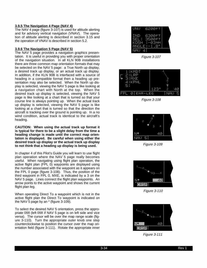
3-34 Rev 1
3.9.5 The Navigation 4 Page (NAV 4)The NAV 4 page (figure 3-107) is used for altitude alertingand for advisory vertical navigation (VNAV). The opera-tion of altitude alerting is described in section 3.15 andthe operation of VNAV is described in section 5.2.
3.9.6 The Navigation 5 Page (NAV 5)The NAV 5 page provides a navigation graphics presen-tation. It is useful in providing you with proper orientationof the navigation situation. In all KLN 90B installationsthere are three common map orientation formats that maybe selected on the NAV 5 page: a True North up display,a desired track up display, or an actual track up display.In addition, if the KLN 90B is interfaced with a source ofheading in a compatible format then a heading up pre-sentation may also be selected. When the North up dis-play is selected, viewing the NAV 5 page is like looking ata navigation chart with North at the top. When thedesired track up display is selected, viewing the NAV 5page is like looking at a chart that is turned so that yourcourse line is always pointing up. When the actual trackup display is selected, viewing the NAV 5 page is likelooking at a chart that is turned so that the direction theaircraft is tracking over the ground is pointing up. In a nowind condition, actual track is identical to the aircraft’sheading.
CAUTION: When using the actual track up format itis typical for there to be a slight delay from the time aheading change is made until the correct map orien-tation is displayed. Be careful when using either thedesired track up display or the actual track up displayto not think that a heading up display is being used.
In chapter 4 of this Pilot’s Guide you will learn to use flightplan operation where the NAV 5 page really becomesuseful. When navigating using flight plan operation, theactive flight plan (FPL 0) waypoints are displayed usingthe number associated with the waypoint as it appears onthe FPL 0 page (figure 3-108). Thus, the position of thethird waypoint in FPL 0, MXE, is indicated by a 3 on theNAV 5 page. Lines connect the flight plan waypoints. Anarrow points to the active waypoint and shows the currentflight plan leg.
When operating Direct To a waypoint which is not in theactive flight plan the Direct To waypoint is indicated onthe NAV 5 page by an * (figure 3-109).
To select the desired NAV 5 orientation, press the appro-priate C (left C if NAV 5 page is on left side and viceversa). The cursor will be over the map range scale (fig-ure 3-110). Turn the appropriate outer knob one stepcounterclockwise to position the cursor over the map ori-entation field (figure 3-111). Rotate the appropriate inner
VNV 6200ft| | IND 6300ft| SEL: 3500ft| KOSH :-03nm| ANGLE:-1.8^| NAV 4
Figure 3-107
1:KMDT | ; 2:LRP | < 3:MXE | 4:KPHL | 5: | |123^ 40 FPL 0 enr-leg NAV 5
4
3
2
Figure 3-108
| | | | | NŸ 40| NAV 5
*1
2
3 4ij
Figure 3-109
12
3 4ij
| | | | | NŸ 40| CRSR
Figure 3-110
12
3 4ij
| | | | | NŸ 40| CRSR
Figure 3-111

3-35 Rev 1
knob to display N? for North up, DTK? for desired track up(figure 3-112), TK? for actual track up (figure 3-113), orHDG? for heading up (figure 3-114). The heading upselection is not presented as a choice if heading is notprovided to the KLN 90B. If the cursor is moved to themap range scale using the outer knob or if the cursor isturned off with the C button, then the DTK?, TK?, orHDG? annunciation is replaced with the actual value. The123 ° displayed in the lower left corner of figure 3-115shows how the actual track is displayed when the cursoris not over the map orientation field as it was in figure 3-113.
If a heading input is available to the KLN 90B then head-ing up is usually the best map orientation to select.Otherwise, track up display is usually preferred for use inflight. However, the track up display is only usable whenthe aircraft is moving 2 knots or more so the North up dis-play may be a good choice while operating with very slowground speeds.
Notice that in both the North up format and the desiredtrack up format, the aircraft’s position is depicted by a dia-mond. In the actual track up format and the heading upformat, the aircraft’s position is depicted by an aircraftsymbol.
The range scale is displayed in the lower right corner ofthe NAV 5 page. The range scale indicates the distancefrom the aircraft’s position (the diamond or aircraft sym-bol) to the top of the screen. Range scale selections from1 NM to 1000 NM may be made by pressing the appropri-ate C and turning the appropriate inner knob. Forexample, figure 3-116 illustrates the results of changingthe range scale of the map in figure 3-110 from 40 nauti-cal miles to 15 nautical miles.
When the NAV 5 page is displayed on the left side of thescreen and any selected waypoint page is displayed onthe right side, the location of the selected waypoint is indi-cated by a “+” on the NAV 5 page (figure 3-117). Ofcourse, the display scale must be chosen which allowsthe selected waypoint to be displayed.
| | | | | DTKŸ 40| CRSR
2
3
4
ij
Figure 3-112
| | | | | TKŸ 40| CRSR
2
3
4
Figure 3-113
| | | | | HDGŸ 40| CRSR
2
3
4
Figure 3-114
| | | | | 123^ 40| CRSR
2
3
4
Figure 3-115
| | | | |NŸ 15| CRSR
3
2
ij
Figure 3-116
| PTW D + |POTTSTOWN | L |116.50 9^W |N 40^13.33' NŸ 40|W 75^33.64' NAV 5 enr-leg VOR
12
3 4ij
Figure 3-117

3-36 Rev 1
3.9.7 The Super NAV 5 PageRegardless of whether you ultimately learn to use just theDirect To capabilities of the KLN 90B or whether youmaster all of its sophisticated features, you will definitelywant to learn how to use the Super NAV 5 page! TheSuper NAV 5 page provides you with a true moving mapdisplay of your present position and route of flight inrelation to nearby navaids and airports. The Super NAV5 page is displayed by selecting the NAV 5 page on boththe left and right sides at the same time (figure 3-118).As you can see, the Super NAV 5 page has a unique for-mat unlike any other KLN 90B page. This is done so thatyou get the maximum amount of screen dedicated tographics display. There are no page display indicators inthe lower left and right segments of the display to tell youthe Super NAV 5 page is being displayed. However, youwill soon learn to recognize the Super NAV 5 page by itsunique format. The mode annunciation, which normallyappears in the lower center segment of the screen, is nowlocated on the far left side. The message prompt is nowlocated in the lower left corner of the graphics display.
The left side of the Super NAV 5 page shows thefollowing information:
• Distance to the active waypoint• The active waypoint identifier• Mode of operation• Groundspeed• *Estimated time enroute, cross track error, or VNAV
status• *Desired track, bearing to active waypoint, or radial
from active waypoint• *Actual track, bearing to active waypoint, or radial from
active waypoint
The lines above with an * in front can be configured bythe pilot to display any of the items listed. This is done bypressing the left C and rotating the left outer knob coun-terclockwise until it is over the desired line. Turn the leftinner knob to choose between items for a given line.When all selections are complete, turn off the cursor bypressing the left C.
The map scale is also changed by using the left cursorbutton. To change the map scale, press the left C toplace the cursor over the map scale factor at the bottomleft corner of the map display. Turn the left inner knob toselect a map scale. The map scale choices are the sameas for the NAV 5 page except there is an additionalchoice, AUTO, that is located between the 1 and 1000nm scale factors. The AUTO scale factor will automati-cally choose the smallest map scale that will display theactive waypoint and, if there is one, the waypoint after theactive waypoint. Choosing the AUTO scale factor meansthere is one less item for you to worry about. This is espe-cially helpful when conducting non-precision approachesusing the KLN 90B.
9.2 oq LRP | xy-«} | 200 uv áà0:03| ûü113^| †ü113^|60 KMDT
LRP
MXE
KPHL
Figure 3-118

3-37 Rev 1
Like the NAV 5 page, the Super NAV 5 page shows agraphics depiction of the direct to waypoint or the way-points making up the active flight plan. But surprise num-ber one is that the Super NAV 5 page shows alphanu-meric waypoint identifiers on the graphics display to makeorientation even easier for you.
Now surprise number two. You may elect to have nearbyVORs, NDBs, and/or airports added to the graphics dis-play! To do so, press the right C to display a pop upmenu on the right side of the screen (figure 3-119).Notice from the menu that a circle with a dot in the centerrepresents a VOR, a smaller circle represents a NDB,and a small diamond represents an airport. The VORs,NDBs, and airports displayed are those from the nearestwaypoint lists described in section 3.7.3, “Nearest andComplete Waypoint Scan Lists.”
When the menu is first displayed the cursor will be on theVOR selection field. Rotate the right inner knob to displayone of the following: TLH, LH (figure 3-120), H, or OFF.
TLH Terminal, low altitude, and high altitude VORs areselected. In addition, VORs of undefined class willbe displayed. In some parts of the world VORs arenot classified into one of the three standard classes:therefore, TLH must be selected to display theseundefined class VORs.
LH Only low altitude and high altitude VORs will be dis-played.
H Only high altitude VORs will be displayed.
OFF No VORs displayed
In a like manner NDBs and/or airports may be selectedby first using the right outer knob to move the cursor overthe NDB or APT selection field and then using the rightinner knob to select ON or OFF. The example in figure3-121 shows low and high altitude VORs as well as NDBshaving been selected. Notice that the range scale hasbeen changed from 60 nm to 40 nm.
The map orientation can be changed by moving the cur-sor to the bottom line of the pop-up menu and rotating theright inner knob. The map orientation choices are thesame as for the NAV 5 page: North up, desired track up,actual track up, or heading up (if a proper source of head-ing is provided). Remember that for actual track up,graphics are displayed only when the aircraft’s ground-speed is greater than 2 knots.
When the desired selections have been made, press theright C to remove the menu (figure 3-122).
LRP
ETX
RAVBZJ
LQX
AB 8.6 oq VOR: LHLRP | NDB: ONxy-«} | APT:OFF 200 uv 113^†üŸáà0:03|ûü113^|†ü113^|40
Figure 3-121
LRP
9.1 oqLRP |xy-«} | 200uváà0:03|ûü113^|†ü113^|60
ETX
RAVBZJ
LQX
AB
APG
Figure 3-122
KMDT
LRP
8.6 oq VOR: LHLRP | NDB:OFFxy-«} | APT:OFF 200 uv 113^†üŸáà0:03|ûü113^|†ü113^|60
ETX
RAV
Figure 3-120
KMDT
LRP
8.6 oq VOR:OFF LRP | NDB:OFF xy-«} | APT:OFF 200 uv 113^†üŸ áà0:03| ûü113^| †ü113^|60
Figure 3-119

3-38 Rev 1
The last surprise for this page is that it is possible for youto change the active waypoint to any of the flight planwaypoints without having to leave this very useful page.This is done by pulling on the right inner knob to place itin the “out” position. This will create a “window” at thebottom right corner of the display that will initially containthe active waypoint in reverse video (figure 3-123). Thewaypoint contained in this “window” will be the defaultwaypoint when D is pressed. By turning the right innerknob it is possible to scan through the waypoints of theactive flight plan. Turning the knob clockwise will scanthrough the waypoints in sequence until the end of theflight plan is reached. Turning the knob counter-clockwisewill scan through the active flight plan in reverse orderuntil the beginning of the flight plan is reached. Pushingthe right inner knob back to the “in” position will removethe “window” from the graphics portion of the display. Anexample of how to use this technique is presented in sec-tion 4.3.2.
The following operational hints will make using the SuperNAV 5 more enjoyable.
• It is easy to clutter the display with so much data thatit is unusable. Select a range scale that allows anuncluttered presentation of the chosen VORs, NDBs,and airports. Or, select another combination of VORs,NDBs, and airports from the menu. Experiment andcontinue to make new selections for different phasesof your trip. For example, you may find that in theenroute part of the flight selecting high altitude VORsprovide you with enough information, while in the ter-minal area you select a smaller range scale and selectmore items.
• Press @ to instantly declutter the VOR, NDB, andairport selections from the graphics display. Flightplan and Direct To waypoints will still be displayed.Press @ again to restore the selections.
• While taxiing on the airport or flying in the traffic pat-tern, select the 1 NM or 2 NM scale to display the air-port runway diagram instead of the usual airport dia-mond symbol. All runway designations are shown onthe 1 NM scales (figure 3-124). If the 2 NM scale isselected, then the runway designations are shownonly for the longest runway. If your KLN 90B is notprovided a heading input you may wish to select aNorth up display while the aircraft is on the airportsince an actual track up graphics presentation canonly be displayed when the aircraft is moving at least2 knots.
CAUTION: The NAV 5 and Super NAV 5 pages do notdisplay weather, terrain, special use airspace, orother data.
355 oqKTIK |xy-«} | 0 uváà-\--|ûü039^|†ü---^|1
14R
32R
32L
KRNDij
Figure 3-124
LRP
ETX
RAVBZJ
LQX
AB
APG
9.0 oq LRP | xy-«} | 200 uv áà0:03| ûü113^| †ü113^|40 LRP
Figure 3-123

3-39 Rev 1
3.10 SPECIAL USE AIRSPACE ALERT
The KLN 90B database contains the location of areas ofspecial use airspace (SUA). The types of SUA areasstored in the database and the abbreviations used todenote these areas are the following:
Class B CL BClass C CL CControl Area (used outside USA) CTATerminal Area (used outside USA) TMAAlert Area ALRTCaution Area CAUTDanger Area DNGRMilitary Operations Area MOAProhibited Area PROHRestricted Area RESTTraining Area TRNGWarning Area WARN
The KLN 90B will normally alert you prior to entering oneof these areas with a message prompt. When theMessage page is viewed it will display AIRSPACEALERT and will also display the name and type of thespecial use airspace (figure 3-125). If the special use air-space is a Class B, Class C, CTA, or TMA, the messagepage will also instruct you to see the Airport 4 page (air-port communications) for the primary airport so that thecorrect communications frequency may be determined(figure 3-126).
The SUA alert feature is three dimensional. The SUAareas are stored in the KLN 90B database with regard toaltitude when the actual SUA altitude limitations arecharted in terms of mean sea level (MSL). Therefore, ifyou are flying either above or below an SUA area youwon’t be inconvenienced with nuisance alert messages.However, if the actual lower limit of a SUA is charted interms of an altitude above ground level (AGL), then it isstored in the KLN 90B as all altitude below the upper limitof the SUA. If the actual upper limit of an SUA is chartedin terms of AGL, it is stored in the KLN 90B as “unlimited”.
If the altitude input to the KLN 90B is pressure altitudefrom an altitude encoder or air data computer, then youmust manually update the KLN 90B with an altimeter set-ting (baro correction) in order to receive accurate SUAalerting. You may easily update the altimeter setting bypressing the A button to display the Altitude page(figure 3-127). The cursor will be over the inches field if“inches” was previously selected on the SET 7 page. If“millibars” was selected on the SET 7 page then the cur-sor will be over the first two digits of the millibar field. Theleft inner knob is used to change the digits and the leftouter knob is used to move the cursor to the desired posi-tion. When the altimeter setting is complete, press A toreturn to the pages previously in view.
CAUTION: Failure to keep the altimeter baro settingupdated will result in inaccurate special use airspacealerting. If this feature is used, it is a good idea to
ALTITUDE | |BARO:29.92"|ALERT: OFF | | | CRSR
Figure 3-127
AIRSPACE ALERT: COLUMBUS FOUR MOA MEM CENTER 1000ft t] 18000ft enr-leg msg
Figure 3-125
AIRSPACE ALERT: OMAHA CL C SEE KOMA APT 4 PAGE BELOW 5000FT enr-leg msg
Figure 3-126

3-40 Rev 1
update the altimeter baro setting on the ALT pageeach time you make a change to an aircraft’s altime-ter setting.
NOTE: If there is no altitude input to the KLN 90B, all alti-tudes will be regarded as being within the boundary of theSUA area.
Only the outer lateral boundaries are stored for Class B,Class C, CTA, and TMA airspace. These SUA areas arestored as “cylinders” of airspace so all altitudes below theupper limit of these areas are considered to be in theSUA.
10 MIN2 MILES
Figure 3-128
The message prompt for a special use airspace alert willoccur when the aircraft’s position is at a point such that aprojection of the aircraft’s existing track over the ground isapproximately 10 minutes from penetrating the outerboundary of one of these areas. It will also occur if theaircraft is within approximately two nautical miles of oneof these areas even if the aircraft’s projected track overthe ground won’t actually penetrate the SUA area (figure3-128). If one of the SUA areas is penetrated, anothermessage will state: INSIDE SPC USE AIRSPACE.
SPECIAL USE AIRSPACE ALERT

3-41 Rev 1
The SUA alert feature may be disabled (or enabled) onthe Setup 8 (SET 8) page, shown in figure 3-129. Afterdisplaying the SET 8 page on the left side, press the leftC to turn on the left cursor function. The left inner knobis used to display AIRSPACE ALERT ENABLE or AIR-SPACE ALERT DISABLE.
If the SUA alert feature has been enabled, the KLN 90Ballows you to select a vertical buffer on the SET 8 page(figure 3-130) in order to provide an additional layer ofprotection from inadvertently entering a SUA area. Toselect a vertical buffer, make sure the SUA alert featurehas been enabled. Press the left C to turn on the leftcursor and then use the left outer knob to move the cur-sor over the first position of the vertical buffer (figure 3-131). Use the left outer knob to position the cursor andthe left inner knob to select each number (figure 3-132).The buffer may be selected in one hundred foot incre-ments. After the desired selection has been made, pressthe left C to turn off the cursor function.
The vertical buffer serves to “stretch” the SUA area inboth directions by the selected buffer altitude. For exam-ple, let’s say you have selected a buffer of 1000 feet andthe actual SUA area exists from 5,000 feet MSL to 12,000feet MSL. In this case you will receive SUA alert mes-sages if you fly at any altitude between 4,000 and 13,000feet MSL.
CAUTION: It is the pilot’s responsibility to avoidthose areas of special use airspace where ATC clear-ance to penetrate is required but has not beenobtained. The KLN 90B’s special use airspace alert isonly a tool to assist the pilot and should never berelied upon as the sole means of avoiding theseareas.
NOTE: Special Use Airspace alerting is disabled when inthe approach arm or approach active modes.
AIRSPACE | ALERT | ENABLE | | VERT BUFFER| ±00500ft| SET 8
Figure 3-130
AIRSPACE | ALERT | DISABLE | | | |SET 8
Figure 3-129
AIRSPACE | ALERT | ENABLE | | VERT BUFFER| ±00500ft| CRSR
Figure 3-131
AIRSPACE | ALERT | ENABLE | | VERT BUFFER| ±01000ft| CRSR
Figure 3-132

3-42 Rev 1
3.11 VIEWING THE WAYPOINT PAGES
You learned in section 3.7, “SELECTING WAYPOINTS”,the different means of selecting the desired waypoint.You will now see what information may be displayed foreach of the waypoint types (airport, VOR, NDB, intersec-tion, and supplemental).
3.11.1 Airport PagesThere are eight airport pages (APT 1, APT 2, ..., APT 8)for every airport in the published database. The databaseprimary area contains public use and military airports thathave a runway at least 1000 feet in length (see section2.2, "Database Coverage Areas and Contents"). We willuse Orlando Executive airport to illustrate what iscontained on the airport pages.
3.11.2 The Airport 1 Page (APT 1)See figure 3-133.
• Airport identifier. An arrow precedes the identifier if itis the active waypoint.
• Airport name.
• If the airport underlies the outer boundary of a Class Bor C airspace, CTA (Control Area - used outsideUSA), or TMA (Terminal Area - used outside USA),the letters CL B, CL C, CTA, or TMA, respectively,will appear on the left side of this line. Note that thereis no altitude information applied to this criteria.
In addition, if the airport is a military airport the lettersMILTRY will appear on the right side of this line. If theairport is a private airport, the letters PRIVAT willappear.
• The latitude and longitude of the airport referencepoint (the “official” location of the airport).
As shown in figure 3-134, the APT 1 page has a differentformat when it is displayed as one of the nine nearest air-ports (see section 3.7.3 “Nearest And Complete WaypointScan List” and section 3.7.3.1 “Nearest Airports In AnEmergency”.
• To the right of the airport identifier are the letters “NR”followed by a number designating the nearest airport(NR 1), second nearest airport (NR 2), etc. to the air-craft’s present position.
• The length, surface, and lighting of the longest run-way.
• The bearing and distance to the airport.
|=KORL nr 1 |EXECUTIVE | | 5998' HRD |L 132^t] | 03.1nm
Figure 3-134
|=KORL |EXECUTIVE | |CL B |N 28^32.71' |W 81^19.99'
Figure 3-133

3-43 Rev 1
3.11.3 The Airport 2 Page (APT 2)See figure 3-135.
• Airport identifier. An arrow precedes the identifier if itis the active waypoint.
• The city where the airport is located.
• The state if the airport is located in the United States,the Province if located in Canada, or the country out-side the United States and Canada. A listing of theabbreviations used for States, Provinces, and coun-tries is contained in Appendix D.
• Airport elevation. The elevation is rounded to thenearest 10 feet.
• Time in relationship to UTC (Zulu). Z-05, for example,indicates local standard time is five hours behind UTCtime. If the airport is located in an area whichobserves daylight savings time, the information inparentheses shows the daylight savings time in rela-tionship to UTC.
• Instrument approach information.
ILS - airport has an ILS approach.MLS - airport has an MLS approach.ILS/MLS - airport has ILS and MLS approaches.NP APR - airport has a non-precision approach
and no ILS or MLS.NO APR - airport does not have an instrument
approach.
• The symbol (R) designates that the airport is servicedby an Approach/Departure control facility having radarcapability. If you are on an instrument flight plan, youknow whether to expect vectors to the final approachcourse or whether you will have to do your own transi-tion. If you are VFR, you know whether or not theApproach/Departure control is capable of providingseparation advisories.
3.11.4 The Airport 3 Page (APT 3)The function of the APT 3 page is to display runway infor-mation for the selected airport. For many airports the firstAPT 3 page depicts a North up runway diagram for theairport as shown in figure 3-136 for KORL.
NOTE: This runway diagram is present only for those air-ports where Jeppesen’s data contains the position of therunway thresholds.
| | | | | | APT[3
13
31
25
07
Figure 3-136
|=KORL |ORLANDO FL | |ELV 110ft |Z-05(-04DT) |ILS (R) APT 2
Figure 3-135

3-44 Rev 1
The primary APT 3 page (figure 3-137) follows the run-way diagram. Runway designation, lighting, and types ofsurface for up to five runways are displayed in order oflength, beginning with the longest. Since there are manytimes when all of an airport’s runway information does notfit on one page, additional APT 3 pages are used to dis-play the data. Remember that a “+” inserted between thepage type and the number (APT+3 in this case) is used toindicate that there is more than one Airport 3 page.
• The letters “RT” followed by a runway designationindicate that the runway normally has a right handtraffic pattern. In figure 3-137, RT 25 31 designatesthat runways 25 and 31 have a right hand traffic pat-tern.
• Runway number designation for both ends of the run-way.
• Runway lighting availability.L - runway lighting sunset to sunriseLPC - runway lighting is pilot controlledLPT - runway lighting is part-time or on-
request-blank indicates no runway lighting
• Runway length in feet.
• Runway surface:HRD - hard surface (includes asphalt,
concrete, pavement, sealed, tarmac, brick, and bitumen)
TRF - turfGRV - gravelCLY - claySND - sandDRT - dirtICE - iceMAT - steel mattingSHL - shaleSNW - snow
- Blank indicates runway surface type is unknown.
In the event that there is no runway information for anairport, the following message is displayed on the APT 3page:
RUNWAY DATA NOT AVAILABLE
|=KORL | RT 25 31 |07 /25 L | 5998' HRD |13 /31 L | 4638' HRD APT[3
Figure 3-137

3-45 Rev 1
3.11.5 The Airport 4 Page (APT 4)See figure 3-138
The APT 4 page is used to display communication fre-quencies for the selected airport.
• Airport identifier. An arrow precedes the identifier if itis the active waypoint.
• Frequencies for:ATIS - automatic terminal information service PTAX - pre-taxi clearanceCLR - clearance deliveryGRND - ground controlRAMP - ramp/taxi controlTWR - towerUNIC - unicomMCOM - multicomCTAF - common traffic advisory frequencyRDO - radioMF - mandatory frequencyATF - aerodrome traffic frequencyAFIS - aerodrome flight information serviceCL B - Class B (VFR frequency)CL C - Class C (VFR frequency)TRSA - terminal radar service area (VFR
frequency)CTA - control area (VFR frequency used out
side USA)TMA - terminal area (VFR frequency used
outside USA)APR - approach controlDEP - departure controlCTR - center (when center is used for
approach/departure control)ARVL - arrivalRDR - radar only frequencyDIR - director (approach control/radar)ASOS - automated surface observation systemAWOS - automatic weather observing stationAAS - aeronautical advisory servicePCL - pilot controlled lighting
In addition to the standard VHF frequencies shown in fig-ure 3-138, HF frequencies are shown at airports that uti-lize “high frequency” communications that fall in the 2000kHz to 30,000 kHz frequency band. These are typicallyused in remote areas of the world. One way to tell HFfrequencies is that they do not contain a decimal point. Adisplay of 6547 would indicate a frequency of 6,547 kHz.
Airports which have numerous communication frequen-cies will have multiple Airport 4 pages indicated byAPT+4.
Part-time operation, such as for a control tower, is indi-cated with an * to the left of a frequency.
|=KORL |ATIS*127.25 |CLR *118.05 |GRND*121.40 |TWR *118.70 |CTAF*118.70 APT[4
Figure 3-138
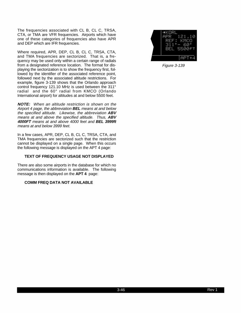
3-46 Rev 1
The frequencies associated with CL B, CL C, TRSA,CTA, or TMA are VFR frequencies. Airports which haveone of these categories of frequencies also have APRand DEP which are IFR frequencies.
Where required, APR, DEP, CL B, CL C, TRSA, CTA,and TMA frequencies are sectorized. That is, a fre-quency may be used only within a certain range of radialsfrom a designated reference location. The format for dis-playing the sectorization is to show the frequency first, fol-lowed by the identifier of the associated reference point,followed next by the associated altitude restrictions. Forexample, figure 3-139 shows that the Orlando approachcontrol frequency 121.10 MHz is used between the 311°radial and the 60° radial from KMCO (OrlandoInternational airport) for altitudes at and below 5500 feet.
NOTE: When an altitude restriction is shown on theAirport 4 page, the abbreviation BEL means at and belowthe specified altitude. Likewise, the abbreviation ABVmeans at and above the specified altitude. Thus, ABV4000FT means at and above 4000 feet and BEL 3999ftmeans at and below 3999 feet.
In a few cases, APR, DEP, CL B, CL C, TRSA, CTA, andTMA frequencies are sectorized such that the restrictioncannot be displayed on a single page. When this occursthe following message is displayed on the APT 4 page:
TEXT OF FREQUENCY USAGE NOT DISPLAYED
There are also some airports in the database for which nocommunications information is available. The followingmessage is then displayed on the APT 4 page:
COMM FREQ DATA NOT AVAILABLE
|=KORL |APR 121.10 | REF: KMCO | 311^- 60^ | BEL 5500ft | APT[4
Figure 3-139

3-47 Rev 1
3.11.6 The Airport 5 Page (APT 5)The Airport 5 page is used to store and display user-entered remarks. These remarks might include informa-tion on lodging, dining, airport services, or anything elseyou desire to record for later use. Up to 100 airports maycontain these remarks. A remark may contain up to threelines of eleven characters each. Letters, numbers,hyphens, and spaces may be used in the remark. Toenter a remark:
• Select the APT 5 page for the desired airport (figure3-140).
• Press the right C .
• Rotate the right outer knob until the cursor fills theentire third line of the screen (figure 3-141).
• Use the right inner knob to select the first character ofthe remark.
• Use the right outer knob to move the flashing portionof the cursor to the second cursor position, and thenuse the right inner knob to select the second charac-ter.
• Use the right outer and inner knobs to select the restof the first line of the remark (figure 3-142).
• Press E to approve the first line. The cursor willmove to the next line (figure 3-143).
• Use the above procedure to select the characters forthe second and third lines of the remark. Press E toindividually approve each line of the remark.
• Press the right C to turn the right cursor function off(figure 3-144).
The Other 4 page (OTH 4) includes a listing of all airportswhose APT 5 pages contain remarks (figure 3-145). Todelete a previously entered airport remark, select theOther 4 page, position the left cursor over the desired air-port identifier, press @, and then press E. If there aremore than five airports with remarks, you will have to usethe left outer knob to scroll the cursor down the list on theOther 4 page to find the desired airport identifier.
|=KORL |REMARKS: | BESTJET!! | | | CRSR
Figure 3-142
|=KORL |REMARKS: | BESTJET | | | CRSR
Figure 3-143
|=KORL |REMARKS: | BESTJET | MOTEL 407 | 123-4567 | APT 5
Figure 3-144
APTS W/RMKS| KCOS | KDEN | KORL | KHPN | M39 | OTH 4
Figure 3-145
|=KORL |REMARKS: | | | | APT 5
Figure 3-140
|=KORL |REMARKS: | | | | CRSR
Figure 3-141

3-48 Rev 1
3.11.7 The Airport 6 Page (APT 6)The APT 6 page shows aeronautical services available forthe selected airport. These services include customs, fuel,and oxygen availability as well as an indicator to denotethe presence of a landing fee. Refer to figure 3-146.
• Customs information is displayed as follows:
CUSTOMS-FULL Customs facilities are available without restriction
NO CUSTOMS No customs facilities areavailable
CUSTMS-PR Customs facilities are available but require prior request or permission for use
CUSTMS-REST Customs facilities are available on a restricted basis, check with the airport before planning to use
CUSTMS-ADCS Customs are available forprivate aircraft arriving to the U.S.from Canada or Mexico. Advance notice of arrival to customs officers is to be included in the flight plan transmitted to an FAA facility. This code is used when this is the only type customs facility available. The FAA term for the service is “ADCUS”.
(blank) Blank line indicates that customs information is not available in the database.
• The following fuel types are displayed:80 80 octane100 100 octane100LL 100 octane, low-leadMOGAS Automotive fuelJET Jet fuel (any type jet fuel qualifies)NO FUEL No fuel available
• If there are no oxygen services available at theselected airport, the fifth line will display NO OXYGEN.If any type of oxygen service is available, the fifth linewill read OX and the rest of the line will display the spe-cific oxygen service:
H high-pressureHB high-pressure bottledL low-pressureLB low-pressure bottledALL all of the above oxygen
services available
• The sixth line of the APT 6 page denotes the presenceof a landing fee:
LANDING FEE The airport has a landing feeNO LDG FEE The airport does not have a
landing feeNO FEE INFO Jeppesen does not have any
information on whether or not there is a landing fee for this airport
|=KORL | |100 JET | |NO OXYGEN |NO FEE INFO APT 6
Figure 3-146

3-49 Rev 1
3.11.8 The Airport 7 Page (APT 7)The APT 7 page shows the SID and STAR proceduresthat are available for the selected airport. If both SID andSTAR procedures are available then there will be two APT7 pages indicated by APT+7 (figure 3-147). If there are noSID or STAR procedures in the database then this pagewill be as shown in figure 3-148.
The details of this page are presented in section 6.2.
3.11.9 The Airport 8 Page (APT 8)The APT 8 page shows the non-precision approaches thatare available for the selected airport (figure 3-149). Thereis only one APT 8 page. If there are no approaches forthis airport in the database then this page will be as shownin figure 3-150.
The details of this page are presented in section 6.1.
NOTE: If the KLN 90B is not installed to support non-precision approaches, then the APT 8 page will not bedisplayed.
3.11.10 The VOR PageThe VOR page shown in figure 3-151 for Blue Ridge VORis used to illustrate the contents of a VOR page.
• VOR identifier. An arrow precedes the identifier if it isthe active waypoint.
• The letter D appears following the VOR identifier if theVOR has DME capability.
• The name of the VOR.
• The class of VOR:T - terminalL - low altitudeH - high altitudeU - undefined
• The VOR frequency (MHz).
• The published magnetic variation of the VOR.
• The latitude and longitude of the VOR.
As you learned in section 3.7.3, “Nearest And CompleteWaypoint Scan Lists”, you may display the nearest nineVORs to the aircraft’s present position. When a VORpage is displayed as part of the nearest VOR list, the lati-tude and longitude is replaced with the bearing and dis-tance to the VOR (figure 3-152).
|=BUJ D |BLUE RIDGE | L |114.90 8^E |N 33^16.99' |W 96^21.89' VOR
Figure 3-151
Figure 3-147
=KFNL NO SID/STAR FOR THIS AIRPORT IN DATABASE APT 7
KLAXSELECT STAR 1 CIVET4 2 DOWNE4 3 FIM612 VISTA1 APT+7
Figure 3-148
Figure 3-149
KLCG IAP NO APROACH FOR THIS AIRPORT IN DATABASE APT 8
=KFNL IAP 1 NDB 33 2 RNAV 15 3 RNAV 33 4 VOR-A
APT 8Figure 3-150
| ADM D nr 1 |ARDMORE | H |116.70 9^E | 318^t] | 32.6nm VOR
Figure 3-152

3-50 Rev 1
3.11.11 The NDB PageThe NDB page shown in figure 3-153 for Ottawa NDB isused to illustrate the contents of an NDB page.
• NDB identifier. An arrow precedes the identifier if it isthe active waypoint.
• The name of the NDB.
• The NDB frequency (kHz).
• The latitude and longitude of the NDB.
There is also a nearest NDB scan list as explained in sec-tion 3.7.3. When a NDB page is displayed as one of thenearest NDBs the latitude and longitude are replaced withthe bearing and distance to the NDB (figure 3-154).
4.11.12 The Intersection Page (INT)The Intersection pages contain the named low altitude,high altitude, approach, and SID/STAR intersections aswell as outer markers and outer compass locators. TheIntersection page for KENZY outer compass locator (fig-ure 3-155) is used as an example of what is displayed forIntersection pages:
• The intersection, outer marker, or outer compass loca-tor name.
• The location of the intersection, outer marker, or outercompass locator expressed in terms of a radial anddistance from a nearby VOR. The KLN 90B choosesthe closest VOR. Note that it takes a few seconds forthe VOR ident, radial, and distance to be calculatedand displayed.
• The latitude and longitude of the intersection, outermarker, or outer compass locator.
You may also enter the identifier of another nearby way-point in the REF field, and the page will compute and dis-play the radial and distance from the nearby waypoint tothe intersection. This information is not stored with theIntersection page and is lost when leaving the page. Tocalculate the radial and distance from a nearby waypoint:
1. Display the desired Intersection page.
2. Press the right C to turn on the right cursor function.
3. Rotate the right outer knob until the cursor is posi-tioned over the identifier adjacent to REF (figure 3-156).
4. Use the right inner and outer knobs to select thedesired identifier (figure 3-157).
|=KENZY |REF: MKC |RAD: 152.2^ |DIS: 3.7nm |N 39^13.25' |W 94^33.84' INT
Figure 3-155
| DNI nr 1 |DENISON | |FREQ 341 | 055^t] | 06.5nm NDB
Figure 3-154
|=OWI |OTTAWA | |FREQ 251 |N 38^32.55' |W 95^15.26' NDB
Figure 3-153

3-51 Rev 1
5. Press E to display the waypoint page for the identi-fier just entered.
6. Press E to approve the waypoint page. TheIntersection page is displayed with the computedradial and distance (figure 3-158).
7. Press the right C to turn off the right cursorfunction.
3.11.13 The Supplemental Waypoint Page (SUP)Supplemental waypoints are user-defined waypoints thathave not been defined specifically as an airport, VOR,NDB, or intersection. The procedure for creatingsupplemental waypoints is explained in section 5.4.4.Supplemental waypoints also include ARTCC “Center”waypoints and “Reference” waypoints which you will learnto create later in chapter 5 of this Pilot’s Guide. Figure 3-159 shows an example of a typical SupplementalWaypoint page. The following information is displayed ona Supplemental waypoint page:
• The name or identifier of the supplemental waypoint.
• The position of the supplemental waypoint expressedin terms of a radial and distance from a nearby VOR.
• The latitude and longitude of the supplementalwaypoint.
In addition, you may enter the identifier of another nearbywaypoint in the REF field and the page will compute anddisplay the radial and distance from the nearby waypointto the supplemental waypoint. The procedure for doingthis is identical to that just explained above for an inter-section waypoint. This radial and distance information isnot stored with the Supplemental Waypoint page and islost when leaving the page.
| KAUSI |REF: AUS |RAD: 41.4^ |DIS: 09.1nm |N 30^23.90' |W 94^34.30' SUP
Figure 3-159
|=KENZY |REF: MKC |RAD: 152.2^ |DIS: 3.7nm |N 39^13.25' |W 94^33.84' CRSR
Figure 3-156
|=KENZY |REF: RIS |RAD: 152.2^ |DIS: 3.7nm |N 39^13.25' |W 94^33.84' CRSR
Figure 3-157
|=KENZY |REF: RIS |RAD: 009.0^ |DIS: 6.2nm |N 39^13.25' |W 94^33.84' CRSR
Figure 3-158

3-52 Rev 1
3.12 FREQUENCIES FOR NEAREST FLIGHTSERVICE STATIONS
The KLN 90B stores in its database the locations of FlightService Stations (FSS) and their remote communicationssites. In addition, the KLN 90B determines which two ofthese FSS points of communication are closest to yourpresent location. What a convenience for you! Next timeyou want to file a flight plan from the air or contact a FSSfor some other reason, you can easily use the KLN 90Bto determine a suitable FSS and the appropriate fre-quency.
NOTE: In some areas of the world the KLN 90B providesthe location of the nearest point of communication with afacility providing information (INF) or radio (RDO) ser-vices.
Select the Other 1 page (OTH 1) on the left side to viewtwo of the nearest points of communication with FlightService Stations. There will normally be two OTH 1pages, one for each of the two points of contact. Thename of the FSS is at the top of the page. There can befrom one to four frequencies included for a point of con-tact (figure 3-160). Remember that in the U.S. the fre-quency 122.00 MHz is used for “Flight Watch” and thefrequency 123.60 MHz is used for Aeronautical AdvisoryService. As you know, it is often possible to communi-cate with a FSS by transmitting on 122.10 MHz and lis-tening on the VOR frequency. In cases like this, the OTH1 page displays the frequencies to use for transmit andreceive and also the VOR name through which you arecommunicating (figure 3-161).
In some parts of the world, high frequency (HF) communi-cations are used for these services. HF frequencies aredisplayed on the OTH 1 page where appropriate.Remember, you can easily recognize HF frequenciesbecause they do not have a decimal point.
3.13 FREQUENCIES FOR AIR ROUTE TRAFFIC CONTROL CENTERS (ARTCC)
The KLN 90B also stores in its database the low altitudeboundaries of each of the ARTCC “Centers”. The KLN90B determines the proper Center to contact and theappropriate frequencies to use for the aircraft’s presentposition. The Other 2 page (OTH 2) is used to displaythis information to you (figure 3-162). Next time you wishto obtain VFR flight following or communicate with Centerfor any reason, you have a quick way to get a frequencyfor establishing contact! Appendix D contains a listing ofCenter abbreviations used on the OTH 2 page.
NOTE: Frequencies for Area Control Centers are dis-played on the OTH 2 page for some areas of the world.
LOS ANGELES| CTR | 118.55| 132.85| | | OTH 2
Figure 3-162
AUSTIN FSS | | 122.20| 122.55| | | OTH[1
Figure 3-160
FT DODGE | FSS | OMAHA VOR | | TX 122.10| REC 116.30| OTH[1
Figure 3-161
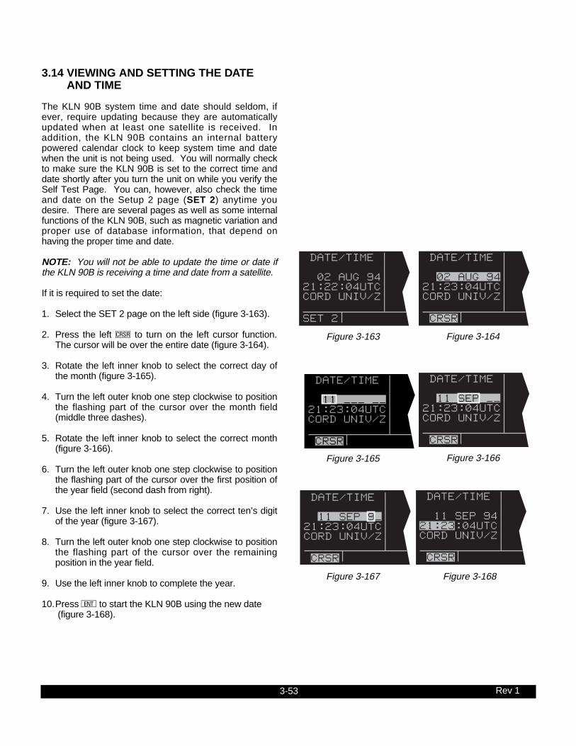
3-53 Rev 1
3.14 VIEWING AND SETTING THE DATE AND TIME
The KLN 90B system time and date should seldom, ifever, require updating because they are automaticallyupdated when at least one satellite is received. Inaddition, the KLN 90B contains an internal batterypowered calendar clock to keep system time and datewhen the unit is not being used. You will normally checkto make sure the KLN 90B is set to the correct time anddate shortly after you turn the unit on while you verify theSelf Test Page. You can, however, also check the timeand date on the Setup 2 page (SET 2) anytime youdesire. There are several pages as well as some internalfunctions of the KLN 90B, such as magnetic variation andproper use of database information, that depend onhaving the proper time and date.
NOTE: You will not be able to update the time or date ifthe KLN 90B is receiving a time and date from a satellite.
If it is required to set the date:
1. Select the SET 2 page on the left side (figure 3-163).
2. Press the left C to turn on the left cursor function.The cursor will be over the entire date (figure 3-164).
3. Rotate the left inner knob to select the correct day ofthe month (figure 3-165).
4. Turn the left outer knob one step clockwise to positionthe flashing part of the cursor over the month field(middle three dashes).
5. Rotate the left inner knob to select the correct month(figure 3-166).
6. Turn the left outer knob one step clockwise to positionthe flashing part of the cursor over the first position ofthe year field (second dash from right).
7. Use the left inner knob to select the correct ten’s digitof the year (figure 3-167).
8. Turn the left outer knob one step clockwise to positionthe flashing part of the cursor over the remainingposition in the year field.
9. Use the left inner knob to complete the year.
10.Press E to start the KLN 90B using the new date(figure 3-168).
DATE/TIME | | 11 SEP 94| 21:23:04UTC| CORD UNIV/Z| | CRSR
Figure 3-168
DATE/TIME | | 11 SEP 9!|21:23:04UTC|CORD UNIV/Z| | CRSR
Figure 3-167
DATE/TIME | | 02 AUG 94| 21:22:04UTC| CORD UNIV/Z| | SET 2
Figure 3-163
DATE/TIME | | 02 AUG 94| 21:23:04UTC| CORD UNIV/Z| | CRSR
Figure 3-164
DATE/TIME | | 11 !!! !!| 21:23:04UTC| CORD UNIV/Z| | CRSR
Figure 3-165
DATE/TIME | | 11 SEP !!| 21:23:04UTC| CORD UNIV/Z| | CRSR
Figure 3-166
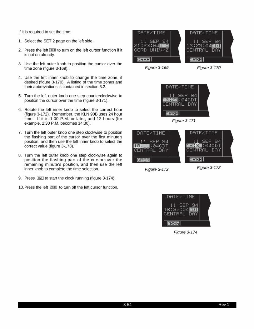
3-54 Rev 1
If it is required to set the time:
1. Select the SET 2 page on the left side.
2. Press the left C to turn on the left cursor function if itis not on already.
3. Use the left outer knob to position the cursor over thetime zone (figure 3-169).
4. Use the left inner knob to change the time zone, ifdesired (figure 3-170). A listing of the time zones andtheir abbreviations is contained in section 3.2.
5. Turn the left outer knob one step counterclockwise toposition the cursor over the time (figure 3-171).
6. Rotate the left inner knob to select the correct hour(figure 3-172). Remember, the KLN 90B uses 24 hourtime. If it is 1:00 P.M. or later, add 12 hours (forexample, 2:30 P.M. becomes 14:30).
7. Turn the left outer knob one step clockwise to positionthe flashing part of the cursor over the first minute’sposition, and then use the left inner knob to select thecorrect value (figure 3-173).
8. Turn the left outer knob one step clockwise again toposition the flashing part of the cursor over theremaining minute’s position, and then use the leftinner knob to complete the time selection.
9. Press E to start the clock running (figure 3-174).
10.Press the left C to turn off the left cursor function.
DATE/TIME | | 11 SEP 94| 21:23:04UTC| CORD UNIV/Z| | CRSR
Figure 3-169
DATE/TIME | | 11 SEP 94| 16:23:04CDT| CENTRAL DAY| | CRSR
Figure 3-170
DATE/TIME | | 11 SEP 94|18:!!:04CDT|CENTRAL DAY| | CRSR
Figure 3-172
DATE/TIME | | 11 SEP 94| 18:37:04CDT| CENTRAL DAY| | CRSR
Figure 3-174
DATE/TIME | | 11 SEP 94| 18:3!:04CDT| CENTRAL DAY| | CRSR
Figure 3-173
DATE/TIME | | 11 SEP 94|16:23:04CDT|CENTRAL DAY| | CRSR
Figure 3-171

3-55 Rev 1
3.15 ALTITUDE ALERTING
If your aircraft does not already have an altitude alertingcapability you may wish to use the KLN 90B’s capability ofassisting you with altitude management during your flying.Altitude alerting allows you to select a target altitude and itthen provides you with an aural alarm 1000 feet prior toreaching the selected altitude, another aural alarm uponreaching the selected altitude, and another aural alarm ifyou deviate from the selected altitude.
NOTE: The altitude alerting function of the KLN 90B doesnot meet FAR Part 91 for turbojet-powered civil airplanes.
To use the altitude alerting:
1. Press A. The Altitude page will be displayed on theleft with the cursor over the first two digits of the altime-ter baro set field. The NAV 4 page will be displayed onthe right with the cursor over the first digit of theselected altitude field (figure 3-175).
NOTE: The altimeter baro set units may be changed frominches to millibars on the SET 7 page.
2. Use the left knobs to update the altimeter baro setting ifrequired. There are three cursor positions. Use the leftouter knob to move the cursor and the left inner knob tochange digits (figure 3-176). With the proper altimeterbaro setting, the indicated altitude (IND) on the rightshould be the same as the aircraft’s actual altimeter.
NOTE: There may be some difference (less than 100 feet)between the indicated altitude (IND) and the aircraft’sactual altitude if the altitude input to the KLN 90B is from analtitude encoder because these encoders only provide alti-tude in 100 foot increments.
3. Turn the left outer knob one step clockwise to positionthe cursor over the ALERT: field (figure 3-177). If OFFis displayed, turn the left inner knob to select ON (figure3-178). When alerting is enabled, an arrow to the rightof ON points to the selected altitude on the right side ofthe screen.
4. Select a warn altitude by using the left outer knob toposition the cursor over the WARN: field (figure 3-179).Use the left inner knob to select the desired warn alti-tude. It is selectable in one hundred foot incrementsfrom 200 feet up to 900 feet. Normally, you will use thesame warn altitude all the time so you only have toenter this the first time you use altitude alerting. Therecommended warn altitude is 300 feet.
ALTITUDE |VNV INACTV BARO:30.13"| ALERT: OFF|IND 09000ft |SEL:05500ft |KMKC :-00nm |ANGLE:-1.3^ CRSR enr-leg CRSR
Figure 3-175
ALTITUDE |VNV INACTV BARO:30.09"| ALERT: OFF|IND 09000ft |SEL:05500ft |KMKC :-00nm |ANGLE:-1.3^ CRSR enr-leg CRSR
Figure 3-176
ALTITUDE |VNV INACTV BARO:30.09"| ALERT: OFF|IND 09000ft |SEL:05500ft |KMKC :-00nm |ANGLE:-1.3^ CRSR enr-leg CRSR
Figure 3-177
ALTITUDE |VNV INACTV | BARO:30.09"|IND 09000ft ALERT: ON =|SEL:05500ft WARN:±300ft|KMKC :-00nm |ANGLE:-1.5^ CRSR enr-leg CRSR
Figure 3-178
ALTITUDE |VNV INACTV | BARO:30.09"|IND 09000ft ALERT: ON =|SEL:05500ft WARN:±300ft|KMKC :-00nm |ANGLE:-1.3^ CRSR enr-leg CRSR
Figure 3-179

3-56 Rev 1
5. Enter the selected altitude one digit at a time in the SELfield of the NAV 4 page by using the right outer knob toposition the cursor over the desired digit and the rightinner knob to change the digits until the entire selectedaltitude is displayed (figure 3-180).
Only the selected altitude field (SEL) and the indicated alti-tude (IND) of the NAV 4 page are used for altitude alerting.The rest of the NAV 4 page is used for vertical navigationwhich is described in chapter 5.
6. Press A to return to the pages previously being dis-played.
7. The aural alarm activates as follows:• 1000 feet prior to reaching the selected altitude -
three short tones• Upon reaching the selected altitude - two short
tones• Deviating above or below the selected altitude by
more than the warn altitude - four short tones.
NOTE: Due to the resolution of the altitude input, it may benecessary to descend slightly below or climb slightly abovethe selected altitude before the two tones are activatedindicating that the selected altitude has been reached. Thisselected altitude alert must be activated to arm the systemfor providing the altitude deviation alert.
The KLN 90B can provide the aural alarm tones in either oftwo ways: it may be connected to an audio input of anaudio amplifier contained in an audio panel so that theaural alarm is heard through the aircraft’s speaker andheadphones. Or the KLN 90B may be interfaced with anexternal tone generator installed in the aircraft.
In order to use altitude alerting, the KLN 90B must have analtitude input. If the altitude input is from an altitudeencoder or from an air data computer not having a baroaltitude output, then it will be necessary for you to manuallyinput the proper altimeter setting in order to get accuratealerting. Remember, the altitude coming from an encoderis pressure altitude and must be corrected with the properaltimeter setting to convert to actual altitude. This altimetersetting is easily accomplished by entering the altimeterbaro setting on the Altitude page. Press A to display theAltitude page. Use the left knobs to make the altimeterbaro setting. Press A again to return to the pages previ-ously being displayed. It’s so easy you have no excusesfor not keeping the baro setting updated!
CAUTION: The altitude alerting feature will only beaccurate if the altimeter baro correction is keptupdated. If altitude alerting is used, it is a good idea toupdate the altimeter baro set on the ALT page eachtime you make a change to the aircraft’s altimeter set-ting.
ALTITUDE |VNV INACTV | BARO:30.09"|IND 09000ft ALERT: ON =|SEL:04000ft WARN:±300ft|KMKC :-00nm |ANGLE:-0.0^ CRSR enr-leg CRSR
Figure 3-180

3-57 Rev 1
The volume of the aural alarm tone is changeable on theSET 9 page (figure 3-181). Press the left C to activatethe left cursor and use the left inner and outer knobs toselect a desired volume between 00 and 99. Increasingnumbers increases the volume.
NOTE: The altitude alerting and height above airport fea-tures can be disabled in the KLN 90B installation harnessso that these features are not selectable by the pilot. Whenthis has been done the SET 5, SET 9, and Altitude pagesdisplay OFF and cannot be changed. In addition, the SET5 and SET 9 pages display the following : FEATURE DIS-ABLED.
ALTITUDE | ALERT | VOLUME: | | 02 | | SET 9
Figure 3-181

3-58 Rev 1
3.16 HEIGHT ABOVE AIRPORT ALERT
The height above airport alert feature can provide you ameans of knowing when you are at traffic pattern altitudeor when you are at a fixed height above the airport whereyou might perform any repetitive duty.
The height above airport feature works as follows: Youenable/disable this feature and select an offset height onthe SET 5 page (figure 3-182). When the height aboveairport alert is enabled, the KLN 90B creates a 5 nmradius cylinder of airspace centered on an airport. Thisairport is any airport that is a Direct To waypoint or is the“TO” waypoint in the active flight plan. The height of thecylinder above the airport is the offset height you selecton the SET 5 page. The KLN 90B adds this offset heightto the elevation stored in the database for the airport.The KLN 90B compares the aircraft’s position relative tothe cylinder and notifies you with an aural alert when theaircraft first penetrates the cylinder (figure 3-183). Thealert consists of a short tone, followed by a long tone, fol-lowed by a short tone.
HT ABOVE | APT ALERT | ON | | APT ELEV | [ 800ft | SET 5
Figure 3-182
5 NM
Airport elevationplus selected offset height
Figure 3-183
HT ABOVE | APT ALERT | ON | | APT ELEV | [ 800ft | CRSR
Figure 3-184
To enable or disable the height above airport alert, pressthe left C. Use the left outer knob to position the cursorover the enable/disable field. Turn the left inner knob toselect ON or OFF as desired. To select the offset height,use the left outer knob to position the cursor over the off-set field (figure 3-184). Turn the left inner knob to selectan offset between 800 feet and 2000 feet. Press the leftC to turn the cursor off.
WARNING: The height above airport alert featuredoes not serve the same function as a radar altime-ter. It does not provide any warning about the air-craft’s actual height above the airport’s surroundingterrain.

3-59 Rev 1
The alert tone is provided in the same way as describedin section 3.15, “Altitude Alerting”. The volume isadjustable on the SET 9 page.
In order to use the height above airport alert, an altitudeinput must be provided to the KLN 90B. If the altitudeinput to the KLN 90B is pressure altitude such as from analtitude encoder or air data computer, then the altitudemust be corrected with the proper altimeter baro setting.This is accomplished on the ALT page as described insection 3.15, “Altitude Alerting.”
CAUTION: The height above airport alert feature willonly be accurate if the altimeter baro correction iscorrect. If the height above airport alert feature isenabled, it is a good idea to update the altimeter baroset on the ALT page each time you make a change tothe aircraft’s altimeter setting.
NOTE: The altitude alerting and height above airport fea-tures can be disabled in the KLN 90B installation harnessso that these features are not selectable by the pilot. Whenthis has been done the SET 5, SET 9, and Altitude pagesdisplay OFF and cannot be changed. In addition, the SET5 and SET 9 pages display the following : FEATURE DIS-ABLED.
3.17 REMOTE MOUNTED ANNUNCIATORS
The KLN 90B has outputs capable of driving two remoteannunciator lights: waypoint alert and message.Although these annunciators are optional, it is desirableto have them mounted in the pilot’s normal scan area sothat these annunciators are easily seen. A typicalannunciator is shown in figure 3-185; however, actualannunciation abbreviations and configurations may be dif-ferent.
In addition, there may be a NAV/GPS switch/annunciatorto switch a CDI or HSI navigation source between theKLN 90B and a VOR/ILS system; a GPS APRswitch/annunciator which allows display and control of theapproach modes (see section 6.1; and a GPS CRSswitch/annunciator which allows changing between Legand OBS modes (see section 5.9.1).
The remote waypoint alert annunciator is on wheneverwaypoint alerting is occurring. See sections 3.8.6 and4.2.2.
The remote message annunciator is on whenever themessage prompt is on. See section 3.5.
WPT
MSG
Figure 3-185
3-60 Rev 1
3.18 SAMPLE TRIP
Just to make sure you are ready to use the KLN 90B fornavigation, let’s go through a sample trip to illustratemany of the features you have learned to use in this sec-tion of the Pilot’s Guide. Our trip will be from Adams field(KLIT) in Little Rock, Arkansas to Mueller Municipal air-port (KAUS) in Austin, Texas. The weather is perfect andyou decide to make the trip VFR and fly direct to Austin.
3.18.1 Pre-Departure1. Apply power to the KLN 90B by pushing the
power/brightness knob to the “in” position.
2. When the screen warms up, adjust the brightness tothe desired level by rotating the power/brightnessknob.
3. Verify that the information on the Self Test page is cor-rect, including the time and date. Enter the altimeterbaro setting. Position the cursor over APPROVE?and press E to approve the Self Test page.
4. Read the Database page. Acknowledge theDatabase page by pressing E.
5. A blank NAV 2 page is now displayed on the left sideon the screen. The APT 4 page for Adams field(KLIT), which shows the communications frequencies,is now displayed on the right side of the screen sinceKLIT was the active waypoint when you last removedpower from the KLN 90B. The APT 4 page indicatesthat the ATIS frequency is 125.65 MHz, the pre-taxiclearance delivery frequency is 118.95 MHz, theground control frequency is 121.90 MHz, and thetower frequency is 118.70 MHz. After listening toATIS, you contact clearance delivery for your clear-ance out of the Little Rock Class C airspace. Next,you give ground control a call and receive your taxiclearance.
6. By this time the KLN 90B has reached a NAV readystatus. You know this because the NAV 2 page isnow showing a valid present position, in this case 3.8nautical miles on the 320 degree radial from LittleRock (LIT) VOR.
7. Press D to bring up the Direct To page on the leftside. Use the two left knobs to enter the identifier ofMueller Municipal airport (KAUS) by using the leftinner knob to select the characters and the left outerknob to move the flashing part of the cursor to thedesired cursor location.
8. Press E to bring up the APT 1 waypoint page forMueller Municipal airport on the right side.
9. Press E again to approve the waypoint page. TheNAV 1 page is now displayed on the right side of thescreen while the NAV 2 page returns to the left side.The NAV 1 page indicates it is 384 nautical miles toAustin and that the bearing is 225 degrees. Aftertake-off, the NAV 1 page will also display ground-speed and estimated time enroute.
10.You now decide to view the Super NAV 1 page.Rotate the left inner knob to select the NAV 1 page.
3.18.2 Enroute1. You depart from runway 36 at Little Rock and are told
to “maintain runway heading”. After several radar vec-tors for traffic avoidance you are finally cleared oncourse. The D-Bar indicates that the radar vectorshave taken you north of the original course and youdecide to proceed Direct To Austin from your presentposition. To recenter the D-Bar, press D, and thenpress E.
2. In order to determine the minimum enroute safe alti-tude (ESA) for the flight you view the NAV 3 page. Itindicates an ESA of 4300 feet for the trip and mini-mum safe altitude for your present position of 3400feet.
3. After departure control has directed “squawk 1200,frequency change approved”, you decide it would be agood idea to obtain VFR flight following. To obtain thefrequency for Center, select the Other 2 page (OTH2). It indicates that for your position, you should beable to contact Memphis Center on 118.85 MHz.
4. You’ve only flown about 100 nautical miles, but youbegin wondering where you would go if an enginesuddenly started running rough. You decide to usethe KLN 90B to determine where the nearest airportsare from your present location. To view the nearestairports press M, and then press E. The nearestairport is Hope Municipal (M18) which is eight nauticalmiles from your position on a bearing to the airport of11 degrees. You now rotate the right inner knob toview the other APT pages for Hope Municipal. Youlearn, for example, that it is located in Hope,Arkansas, and has two hard surface runways that areeach 5500 feet in length. By pulling the right innerknob to the “out” position, you may now scan clock-wise through the remaining eight airports in the near-est airport list.
5. For the majority of the enroute portion of the flight youselect, the Super NAV 5 page’s moving map display.You do this by selecting NAV 5 on both sides of thescreen. Pressing the right C brings up the waypointdisplay menu on the right side of the screen. Youthen use the right knobs to select APT: ON so thatnearby airports are shown on the moving map display.

3-61 Rev 1
While the display menu is displayed, select the trackup map orientation (TK) as well. Pressing the right Cagain removes the menu from the screen. You selectthe 30 nm range scale on the left side using the leftC and left knobs. You also decide to display ETE,DTK, and TK on the left side of the map display byusing the left knobs.
6. Since it is a good idea to not rely on just one naviga-tion source, you decide to cross check the KLN 90Bposition against other equipment in the aircraft. TheNAV 2 page indicates you are presently located on theTexarkana (TXK) VOR 68 degree radial at a distanceof 19 nautical miles. By tuning your NavigationReceiver and DME to TXK, you are able to confirmthat this is the correct position.
3.18.3 Terminal Area1. About 50 nautical miles from Austin’s Mueller airport
you start preparing for your arrival. Viewing the APT 4page for KAUS you determine that the ATIS fre-quency is 119.20 MHz and tower is 121.00 MHz.
2. A few minutes later, the message prompt begins flash-ing. When you press M, the message page advises:AIRSPACE ALERT - AUSTIN CL C - SEE KAUSAPT 4 PAGE BELOW 4600 FT. The Special UseAirspace Alert feature has determined that you arewithin 10 minutes of penetrating the Austin Class Cairspace. When you view the APT 4 page, you seethat the Class C airspace frequencies are sectorized.You determine from the APT 4 page that the properfrequency to use is 124.90 MHz since you areNortheast of Austin and 124.90 MHz is the appropriatefrequency to use from 3 degrees to 170 degrees.
3. After you call Austin approach control for clearanceinto the Class C airspace, you view the rest of theAPT pages for KAUS to determine the field elevationand available runways. The first APT 3 page showsyou a runway diagram for the airport.
4. After landing, the KLN 90B is turned off either bypulling the power/brightness switch to the “out” posi-tion or with the avionics master switch if one isinstalled.

3-62 Rev 1
THIS PAGE INTENTIONALLY LEFT BLANK
4-1 Rev 1
This is the second of four chapters specifically dealing withoperating the KLN 90B. In this chapter you will learn tocreate and use flight plans. A flight plan is an organizedlisting of waypoints defining your route of flight.
You may feel that you learned all you need to know inchapter 3 about operating the KLN 90B, since you can usethe Direct To operation to fly anywhere you want to go.However, you would be selling yourself and the KLN 90Bshort if you stop there. Using the unit’s flight plan capabili-ties provides more information and, in some respects,
reduces your enroute workload regardless of whether yourflying is done VFR or IFR. Other advantages of creatingflight plans are: (1) the entire route of flight for an upcom-ing trip can be created and stored prior to departure; and(2) the routes for frequently made trips need to be createdjust once and may then be recalled as required for lateruse. Using the KLN 90B only for Direct To operationwould be like flying a retractable gear aircraft with the geardown all the time — you’re just not getting the most out ofyour equipment!
CHAPTER 4 - LEVEL 2 OPERATION
4.1 CREATING AND MODIFYING FLIGHT PLANS
The following rules and considerations apply to KLN 90Bflight plans:
• The KLN 90B is capable of storing in its memory 25flight plans plus an active flight plan.
• Each of the flight plans may contain up to 30 way-points. These waypoints may consist of any combina-tion of published waypoints from the database or usercreated waypoints.
• The flight plans are numbered 0 through 25 (FPL 0,FPL 1, FPL 2, ..., FPL 25).
• The active flight plan is always FPL 0. The standardprocedure is to create a flight plan in one of the flightplans numbered as FPL 1, FPL 2, FPL 3,..., or FPL25. When one of these numbered flight plans is acti-vated, it becomes FPL 0, the active flight plan. ThisPilot’s Guide will refer to FPL 0 as the “active flightplan” and FPL 1 through FPL 25 as the “numberedflight plans.” If desired, a flight plan can be createddirectly in the active flight plan. This avoids creatingthe flight plan in a numbered flight plan and then hav-ing to activate it. The disadvantage is that if a num-bered flight plan is subsequently made active, the oneprogrammed directly into FPL 0 will be lost.
• Modifications may be made to FPL 0 without affectingthe way it is stored as a numbered flight plan.
• Unless Direct To operation is being used, the activeflight plan (FPL 0) must contain at least two way-points. Otherwise, the KLN 90B system will beflagged.

4-2 Rev 1
4.1.1 Creating A Flight PlanA flight plan for a flight from Lakefront airport in NewOrleans, LA. to St. Petersburg/Clearwater, FL.International airport will be used as an example of how tocreate a flight plan. The waypoints making up the flightplan are: KNEW (Lakefront airport), GPT (Gulfport VOR),SJI (Semmes VOR), CEW (Crestview VOR), MAI(Marianna VOR), TLH (Tallahassee VOR), CTY (CrossCity VOR), and KPIE (St. Petersburg/ClearwaterInternational airport. To create the flight plan:
1. Rotate the left outer knob to select the flight plan(FPL) type pages (figure 4-1).
2. Turn the left inner knob to select a flight plan page(preferably other than FPL 0) which does not containa flight plan (figure 4-2). If all of the flight plan pagescontain flight plans, refer to section 4.1.5, “DeletingFlight Plans.”
3. Press the left C to turn on the cursor function for theleft page (figure 4-3).
NOTE: The KLN 90B flight plan operation is designed sothat the first waypoint in the flight plan should always bethe departure point. Remember to enter the “K”, “P”, or“C” prefix for certain airports in the United States, Alaska,or Canada. See section 2.3, “USE OF ICAO IDENTI-FIERS.”
4. Use the left inner knob to select the first character ofthe departure waypoint identifier (figure 4-4).
5. Turn the left outer knob one step clockwise to movethe flashing portion of the cursor over the secondcharacter position, and then use the left inner knob toselect the desired character.
6. Use the above procedure to select the entire identifierfor the first waypoint (figure 4-5).
7. Press E. A waypoint page for the identifier justentered will be displayed on the right side (figure 4-6).If a mistake was made and the wrong waypoint identi-fier was entered, press @ and begin again. If a mis-take was not made but the waypoint identifier justentered isn’t in the database, a page allowing creationof a user defined waypoint will appear on the rightside. Refer to section 5.4, “USER-DEFINED WAY-POINTS”, for instruction on how to define a user cre-ated waypoint.
8. Press E again to approve the waypoint page beingdisplayed. The cursor will move to the secondwaypoint position (figure 4-7).
NOTE: A small number of waypoints are stored in thedatabase as “fly-over” waypoints. These waypoints areassociated with SID/STAR procedures. “Fly-over” means
USE? INVRT?| 1:KMKC | 2:BUM | 3:OSW | 4:TUL | 6:KRVS | FPL 8
Figure 4-1
LOAD FPL 0?| 1: | | | | | FPL 4
Figure 4-2
LOAD FPL 0?| 1: | | | | | CRSR
Figure 4-3
LOAD INVRT?| 1:K | 2: | | | | CRSR
Figure 4-4
LOAD INVRT?| 1:KNEW | 2: | | | | CRSR
Figure 4-5
USE? INVRT?| KNEW 1:KNEW |LAKEFRONT 2: | | CL C |N 30^02.53' |W 90^01.69' CRSR|enr-leg ent|APT 1
Figure 4-6
USE? INVRT?| 1:KNEW | 2: | | | | CRSR
Figure 4-7

4-3 Rev 1
that, for some reason, the governing agencies havedecided that it is important to fly directly over thewaypoint instead of being able to “cut the corner” byusing turn anticipation (see section 4.2.2). In these casesthe KLN 90B will present a waypoint type identificationpage (Figure 4-7a). Simply select the way in which thewaypoint is intended to be used with the left outer knoband press E. If the SID/STAR choice is selected, theKLN 90B will disable turn anticipation for that waypoint (ifpreviously enabled). The KLN 90B will enable turn antici-pation after the waypoint has been passed (if turn antici-pation was previously enabled). If en route is selected,then normal turn anticipation occurs.
9. Use the same procedure to enter the rest of the way-points in the flight plan (figure 4-8). If the flight planconsists of five or more waypoints, the waypoints willautomatically scroll as necessary to allow entry of thenext waypoint.
10.When all of the waypoints have been entered in theflight plan, the left outer knob may be rotated to movethe cursor up and down and manually “scroll” throughthe waypoints making up this flight plan. This is usefulif the flight plan contains six or more waypoints sincenot all of the waypoints can be displayed at one time.When the left outer knob is rotated to the full counter-clockwise position, the cursor will be positioned overUSE? (figure 4-9). If there are more than five way-points in the flight plan, the first four waypoints willthen be displayed followed by the last waypoint in theflight plan. Rotate the left outer knob to move the cur-sor and manually scroll to see the missing intermedi-ate waypoints.
11.Press the left C to turn off the left cursor function.Additional flight plans may now be created in thesame manner.
4.1.2 Activating A Numbered Flight PlanTo activate one of the previously created numbered flightplans:
1. Use the left outer knob to select the flight plan (FPL)type pages.
2. Rotate the left inner knob to select the desired flightplan (figure 4-10).
3. Press the left C to enable the left cursor function.The cursor will appear over USE? (figure 4-11). If youhaven’t left the numbered flight plan page since creat-ing this flight plan, rotate the left outer knob all the waycounterclockwise to position the cursor over USE?
4:CEW | 5:MAI | 6:TLH | 7:CTY | 8:KPIE | 9: | CRSR
Figure 4-8
USE? INVRT?| 1:KNEW | 2:GPT | 3:SJI | 4:CEW | 8:KPIE | CRSR
Figure 4-9
USE? INVRT?| 1:KNEW | 2:GPT | 3:SJI | 4:CEW | 8:KPIE | FPL 4
Figure 4-10
USE? INVRT?| 1:KNEW | 2:GPT | 3:SJI | 4:CEW | 8:KPIE | CRSR
Figure 4-11
SWR | SWR D TYPE WPT |SQUAW |VALLEY L1 EN ROUTE?|113.20 16^E2 SID/STAR?|N 39^10.82' |W120^16.18' CRSR|enr-leg ent|VOR
Figure 4-7a

4-4 Rev 1
4. Press E to activate the flight plan in the order shown(figure 4-12). To activate the flight plan in inverseorder (first waypoint becomes last and last waypointbecomes first), rotate the left outer knob one stepclockwise to position the cursor over USE? INVRT?before pressing E (figure 4-13).
5. The selected flight plan is now displayed as FPL 0, theactive flight plan. Any changes made to FPL 0 will notaffect how this flight plan is stored as the numberedflight plan.
4.1.3 Adding A Waypoint To A Flight PlanA waypoint may be added to any flight plan containingfewer than 30 waypoints. To add a waypoint to a flightplan:
1. Press the left C to enable the left cursor function if itis not on already (figure 4-14).
2. Rotate the left outer knob as necessary to position thecursor over the waypoint identifier which you desire tofollow the waypoint being added. Another way tothink of this is to position the cursor over the locationin the flight plan you wish the new waypoint to beadded. For example, if SJI is presently the thirdwaypoint in the flight plan and you wish to insertBUGLE intersection in the number three position infront of SJI, move the cursor over SJI (figure 4-15).
3. Use the left inner knob to enter the first character ofthe waypoint being inserted. As you begin to turn theknob, the existing waypoint in this position automati-cally jumps down to the next position. In this case,SJI automatically moves to waypoint four (figure 4-16).
4. Use the left outer and inner knobs in the normal man-ner to complete entering the waypoint identifier (figure4-17).
5. Press E to display the waypoint page on the rightside for the identifier just entered.
6. Press E again to approve the waypoint page (figure 4-18).
7. Press the left C to turn off the left cursor function.
| 1:KNEW | 2:GPT | 3:SJI | 4:CEW | 8:KPIE | CRSR
Figure 4-14
| 1:KNEW | 2:GPT | 3:SJI | 4:CEW | 8:KPIE | CRSR
Figure 4-15
| 1:KNEW | 2:GPT | 3:B | 4:SJI | 9:KPIE | CRSR
Figure 4-16
| 1:KNEW | 2:GPT | 3:BUGLE | 4:SJI | 9:KPIE | CRSR
Figure 4-17
| 1:KNEW | 2:GPT | 3:BUGLE | 4:SJI | 9:KPIE | CRSR
Figure 4-18
| 1:KNEW | 2:GPT | 3:SJI | 4:CEW | 8:KPIE | FPL 0
Figure 4-12
USE? INVRT?| 1:KNEW | 2:GPT | 3:SJI | 4:CEW | 8:KPIE | CRSR
Figure 4-13

4-5 Rev 1
4.1.4 Deleting A Waypoint From A Flight PlanTo delete a waypoint from a flight plan:
1. Press the left C to enable the left cursor function if itis not on already.
2. Rotate the left outer knob as necessary to position thecursor over the waypoint to be deleted (figure 4-19).
3. Press @. The letters DEL (delete) will appear to theleft of the identifier and a question mark will appear tothe right of the identifier (figure 4-20). If a mistake wasmade and you do not wish to delete this waypoint,press @.
4. Press E and the waypoint will be deleted from theflight plan. The other waypoints in the flight plan willbe correctly repositioned (figure 4-21).
5. Press the left C to turn off the left cursor function.
4.1.5 Deleting Flight PlansTo delete a flight plan which is no longer required:
1. Display the flight plan (FPL 0, FPL 1, FPL 2,..., or FPL25) which is to be cleared (figure 4-22).
2. Make sure the left cursor function is turned off. If theleft cursor is on, press the left C to turn it off.
3. Press @. The words DELETE FPL? will appear atthe top of the page (figure 4-23). If a mistake wasmade and you do not wish to clear this flight plan,press @.
4. Press E to clear the flight plan (figure 4-24).
| 1:KNEW | 2:GPT | 3:BUGLE | 4:SJI | 9:KPIE | CRSR
Figure 4-19
USE? INVRT?| 1:KNEW | 2:GPT | DEL BUGLE? | 4:SJI | 9:KPIE | CRSR
Figure 4-20
| 1:KNEW | 2:GPT | 3:SJI | 4:CEW | 8:KPIE | CRSR
Figure 4-21
USE? INVRT?| 1:KMKC | 2:BUM | 3:OSW | 4:TUL | 6:KRVS | FPL 8
Figure 4-22
DELETE FPL?| 1:KMKC | 2:BUM | 3:OSW | 4:TUL | 6:KRVS | CRSR
Figure 4-23
LOAD FPL 0?| 1: | | | | | FPL 8
Figure 4-24

4-6 Rev 1
4.1.6 Storing FPL 0 As A Numbered Flight PlanThe active flight plan may be loaded into a numberedflight plan so that it can be recalled for later use. Thismay be desirable, for example, if the active flight plan wasoriginally created on the FPL 0 page and not as a num-bered flight plan. To store the active flight plan as a num-bered flight plan:
1. Select a numbered flight plan page which does notcontain any waypoints (figure 4-25). If none exist, usethe procedure described in n 4.1.5, “DeletingFlight Plans,” to clear a flight plan which is no longerrequired.
2. Press the left C to turn on the left cursor functionwith the cursor over the blank first waypoint position(figure 4-26).
3. Rotate the left outer knob one step counterclockwiseto position the cursor over LOAD FPL 0? (figure 4-27).
4. Press E to load the active flight plan into this num-bered flight plan (figure 4-28).
LOAD FPL 0?| 1: | | | | | FPL 7
Figure 4-25
LOAD FPL 0?| 1: | | | | | CRSR
Figure 4-26
LOAD FPL 0?| 1: | | | | | CRSR
Figure 4-27
USE? INVRT?| 1:KHOU | 2:DAS | 3:LFK | 4:BEKEN | 5:KSHV | FPL 7
Figure 4-28

4-7 Rev 1
4.2 OPERATING FROM THE ACTIVE FLIGHT PLAN
4.2.1 General ProceduresEverything you have learned in this Pilot’s Guide thus faris applicable to using the KLN 90B for flight plan opera-tion. The following rules and considerations apply forflight plan operation while the KLN 90B is in the Legmode:
• Although any of the KLN 90B pages may be utilizedwhile operating along a flight plan, common pageselections are the FPL 0 page on the left side whilesimultaneously displaying one of three Distance/Timepages (D/T 1, D/T 2, D/T 3) or the NAV 5 page (navi-gation graphics) on the right side. The informationcontained on the Distance/Time pages is explainedlater, beginning in section 4.2.5, “The Distance/TimePages”. The Super NAV 5 page is especially usefulfor flight plan operation. It provides you with a visualorientation of your position in the active flight plan anddisplays the alphanumeric identifiers of the flight planwaypoints. Of course the other four Navigation pagesmay also be used extensively. Now would be a goodtime to take a couple of minutes and review the NAV 5and Super NAV 5 pages as they relate to flight planoperation (see sections 3.9.6 and 3.9.7).
• Always verify that you are viewing the active flight planpage (FPL 0) and not one of the other numbered flightplan pages.
• The active leg of the flight plan is designated with a ∑symbol. A leg is defined as the course line between apair of waypoints (a “from” waypoint and a “to”waypoint). The head of the arrow is positioned to theleft of and points to the active “to” waypoint. In figure4-29, GPT is the “to” waypoint. The tail of the ∑ sym-bol is positioned to the left of the “from” waypoint.KNEW is the “from” waypoint in figure 4-29. The ∑symbol is not displayed unless the KLN 90B is actuallyreceiving navigation signals suitable for navigation.(Note: If the unit is in the take-home mode, it hasbeen “tricked” into thinking it is receiving signals andtherefore the ∑ symbol can be displayed). Also, the ∑symbol will not be displayed if Direct To navigation isoccurring. If in doubt as to whether or not Direct Tooperation is occurring, view the NAV 1 page. If the topline shows the Æ symbol (figure 4-30) instead of a“from” waypoint (figure 4-31), then Direct To navigationis occurring. If it is desired to cancel the Direct Tooperation and operate from the active flight plan; pressD, then press @, then press E.
• As flight plan waypoints are reached, the active legsymbol automatically orients itself on the next leg.
; 1:KNEW | < 2:GPT | 3:SJI | 4:CEW | 5:MAI | 8:KPIE | FPL 0
Figure 4-29
$=KHOU | +++++Ê+++++| DIS 278nm| GS 182kt| ETE 1:32| BRG 264^| NAV 1
Figure 4-30
KNEW =GPT | +++++Ê+++++| DIS 52.4nm| GS 182kt| ETE :18| BRG 065^| NAV 1
Figure 4-31

4-8 Rev 1
• If the flight plan contains more waypoints than can bedisplayed on the screen at one time, the page willautomatically scroll as progress is made along theflight plan so that the active leg is always displayed(figure 4-32).
• The last waypoint in the flight plan is always displayedat the bottom of the FPL 0 page, even if all of the way-points in the flight plan can’t be displayed on the pageat one time. To view intermediate waypoints, turn theleft cursor function on and use the left outer knob tomanually scroll through all of the waypoints, asdesired. If scrolling is performed all the way to the endof the flight plan, a blank waypoint position will exist sothat a waypoint may be added to the end of the flightplan (figure 4-33).
4.2.2 Turn Anticipation And Waypoint AlertingPrior to reaching a waypoint in the active flight plan, theKLN 90B will provide navigation along a curved path seg-ment to ensure a smooth transition between two adjacentlegs in the flight plan. That is, the CDI or HSI left/rightdeviation will be referenced to the dashed line in figure 4-34. This feature is called turn anticipation. The transitioncourse is based upon the aircraft’s actual groundspeedand the amount of course angle change between the twolegs. The KLN 90B automatically sequences to the nextleg after passing the midpoint in the transition segment.
Approximately 20 seconds prior to the beginning of turnanticipation, the arrow preceding the active waypointidentifier will begin flashing on the FPL 0 page and on anyNavigation page, Distance/Time page, or waypoint pagedisplaying the active waypoint identifier (figure 4-35). Onthe Super NAV 5 page, the entire active waypoint identi-fier will start to flash. This is called “waypoint alerting”. Ifan external waypoint alert annunciator is mounted in theaircraft, this annunciator will begin flashing at the sametime.
To utilize the turn anticipation feature, start the turn transi-tioning to the next leg in the flight plan at the verybeginning of turn anticipation. This occurs when theexternal waypoint alert annunciator or the active waypointidentifier on the Super NAV 5 page stops flashing andgoes on steady. At this time the KLN 90B will notify youwith a message on the Message page of the new desiredtrack to select on your HSI or CDI.
ADJ NAV IND CRS TO 123°
A message will not be given if the change in desired track(course change) is less than 5°. In addition, a messagewill not be given if the KLN 90B is interfaced with an EHSIor HSI having a course pointer that is automaticallyslewed to the correct desired track.
3:SJI | ; 4:CEW | < 5:MAI | 6:TLH | 7:CTY | 8:KPIE | FPL 0
Figure 4-32
; 4:CEW | < 5:MAI | 6:TLH | 7:CTY | 8:KPIE | 9: | CRSR
Figure 4-33
WPT 1
WPT 2
WPT 3
Figure 4-34
5
; 1:KNEW |KNEW =GPT = 2:GPT |+++++Ê+++++ 3:SJI |DIS 0.4nm 4:CEW |GS 182kt 5:MAI |ETE :00 8:KPIE |BRG 065^ FPL 0 enr-leg NAV 1
Figure 4-35

4-9 Rev 1
The desired track (DTK) displayed on the NAV 3 pagealso changes to the value for the next leg at the beginningof turn anticipation. Turn anticipation becomes inactivewhen transition to the next leg has been made.
In some installtions the KLN 90B can “read” the selectedcourse set on external CDIs or HSIs. In these installationsthe KLN 90B will flash the value of desired track (DTK) onboth the NAV 3 and Super NAV 5 pages when thedesired track and the selected course differ by more than10°. Set the selected course to match the desired track.This will make sure that the orientation “picture” is alwayscorrect.
If desired, turn anticipation may be disabled (or enabled)on the Setup 6 page (SET 6) using the left C and theleft inner knob to select between DISABLE or ENABLE(figure 4-36). If turn anticipation is disabled, navigation isprovided all the way to the waypoint, and waypoint alert-ing occurs approximately 36 seconds prior to actuallyreaching the waypoint.
Figure 4-36
TURN | ANTICIPATE | | ENABLE | | | SET 6
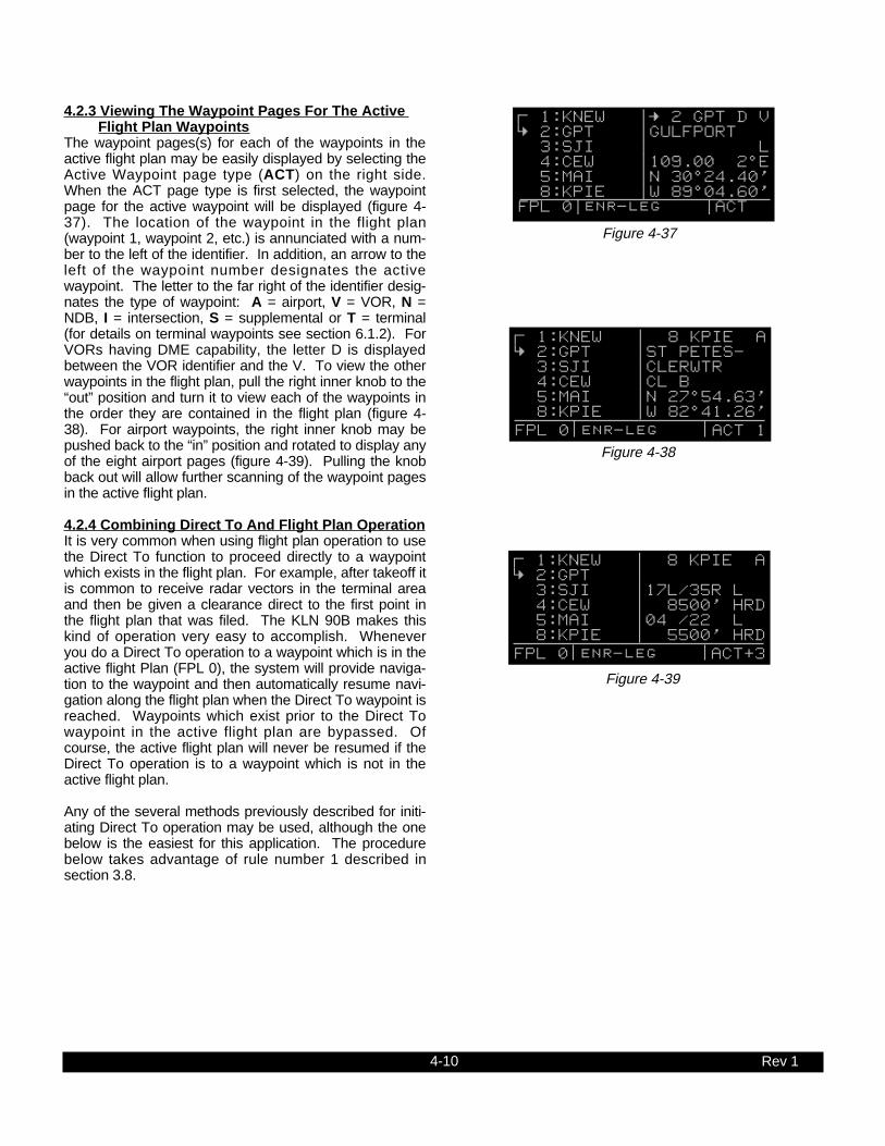
4-10 Rev 1
4.2.3 Viewing The Waypoint Pages For The Active Flight Plan Waypoints
The waypoint pages(s) for each of the waypoints in theactive flight plan may be easily displayed by selecting theActive Waypoint page type (ACT) on the right side.When the ACT page type is first selected, the waypointpage for the active waypoint will be displayed (figure 4-37). The location of the waypoint in the flight plan(waypoint 1, waypoint 2, etc.) is annunciated with a num-ber to the left of the identifier. In addition, an arrow to theleft of the waypoint number designates the activewaypoint. The letter to the far right of the identifier desig-nates the type of waypoint: A = airport, V = VOR, N =NDB, I = intersection, S = supplemental or T = terminal(for details on terminal waypoints see section 6.1.2). ForVORs having DME capability, the letter D is displayedbetween the VOR identifier and the V. To view the otherwaypoints in the flight plan, pull the right inner knob to the“out” position and turn it to view each of the waypoints inthe order they are contained in the flight plan (figure 4-38). For airport waypoints, the right inner knob may bepushed back to the “in” position and rotated to display anyof the eight airport pages (figure 4-39). Pulling the knobback out will allow further scanning of the waypoint pagesin the active flight plan.
4.2.4 Combining Direct To And Flight Plan OperationIt is very common when using flight plan operation to usethe Direct To function to proceed directly to a waypointwhich exists in the flight plan. For example, after takeoff itis common to receive radar vectors in the terminal areaand then be given a clearance direct to the first point inthe flight plan that was filed. The KLN 90B makes thiskind of operation very easy to accomplish. Wheneveryou do a Direct To operation to a waypoint which is in theactive flight Plan (FPL 0), the system will provide naviga-tion to the waypoint and then automatically resume navi-gation along the flight plan when the Direct To waypoint isreached. Waypoints which exist prior to the Direct Towaypoint in the active flight plan are bypassed. Ofcourse, the active flight plan will never be resumed if theDirect To operation is to a waypoint which is not in theactive flight plan.
Any of the several methods previously described for initi-ating Direct To operation may be used, although the onebelow is the easiest for this application. The procedurebelow takes advantage of rule number 1 described insection 3.8.
; 1:KNEW |= 2 GPT D V < 2:GPT |GULFPORT 3:SJI | L 4:CEW |109.00 2^E 5:MAI |N 30^24.40' 8:KPIE |W 89^04.60' FPL 0|enr-leg |ACT
Figure 4-37
; 1:KNEW | 8 KPIE A < 2:GPT |ST PETES- 3:SJI |CLERWTR 4:CEW |CL B 5:MAI |N 27^54.63' 8:KPIE |W 82^41.26' FPL 0 enr-leg ACT 1
Figure 4-38
; 1:KNEW | 8 KPIE A < 2:GPT | 3:SJI |17L/35R L 4:CEW | 8500' HRD 5:MAI |04 /22 L 8:KPIE | 5500' HRD FPL 0 enr-leg ACT[3
Figure 4-39

4-11 Rev 1
1. Select the FPL 0 page of the left side.
2. Press the left C and then use the left outer knob toposition the cursor over the desired waypoint (figure 4-40).
3. Press D. The waypoint page for the selectedwaypoint in FPL 0 will be displayed on the right side(figure 4-41).
4. Press E to approve the waypoint page. The DirectTo waypoint identifier in the active flight plan will nowbe preceded by just an arrow (figure 4-42). The ∑symbol is not displayed since there is no “from”waypoint in the flight plan.
An alternative method is to use the Super NAV 5 page toselect the direct to waypoint. This is done by pulling outon the right inner knob. With the inner knob out, it is pos-sible to scan through the waypoints of the active flightplan as described in section 3.9.7. When the desiredwaypoint is highlighted, press D and then E.
If for some reason it is desired to cancel the Direct Tooperation prior to reaching the Direct To waypoint in orderto proceed along the flight plan leg, press D, then press@, and then press E.
4.2.5 The Distance/Time PagesAs stated earlier, it is common to use the Distance/Timepages in conjunction with flight plan operation. TheDistance/Time pages are specially designed to be mostuseful when the active flight plan page (FPL 0) is dis-played simultaneously on the left side.
4.2.6 The Distance/Time 1 Page (D/T 1)When the FPL 0 page is displayed on the left side and theD/T 1 page is displayed on the right side, the distance(DIS) and estimated time enroute (ETE) are displayed foreach of the active flight plan waypoints (figure 4-43). Thedistance displayed is the cumulative distance from the air-craft’s present position to each waypoint along the flightplan route. The ETE is displayed in hours:minutes. IfDirect To operation is occurring to a waypoint that is notin the active flight plan, then the D/T 1 page is blank whenthe FPL 0 page is displayed on the left (figure 4-44).
If a numbered flight plan page (FPL 1 though FPL 25) isdisplayed on the left side, the distances displayed arefrom the first waypoint in the flight plan and have nothingto do with the aircraft’s present position. No ETEs arethen shown (figure 4-45).
; 1:KNEW |= 2 GPT D V < 2:GPT |GULFPORT 3:SJI | L 4:CEW |109.00 2^E 5:MAI |N 30^24.40' 8:KPIE |W 89^04.60' CRSR enr-leg ACT
Figure 4-40
5
DIRECT TO: | SJI D < 2:GPT |SEMMES SJI |17L/35R L H 4:CEW |115.30 5^E 5:MAI |N 30^43.55' 8:KPIE |W 88^21.56' CRSR enr-leg ent VOR
Figure 4-41
1:KNEW | $=SJI 2:GPT |+++++Ê+++++ = 3:SJI |DIS 90.4nm 4:CEW |GS 180kt 5:MAI |ETE :30 8:KPIE |BRG 062^ FPL 0 enr-leg NAV 1
Figure 4-42
; 1:KNEW |DIS ETE < 2:GPT | 34 :11 3:SJI | 76 :25 4:CEW |163 :54 5:MAI |243 1:21 8:KPIE |477 2:39 FPL 0 enr-leg D/T 1
Figure 4-43
|DIS ETE 1:KNEW | 2:GPT | 3:SJI | 4:CEW | 8:KPIE | FPL 0 enr-leg D/T 1
Figure 4-44
USE? INVRT?|DIS ETE 1:KMKC | 2:BUM | 51 3:OSW |126 4:TUL |190 7:KDAL |432 FPL 6 enr-leg D/T 1
Figure 4-45

4-12 Rev 1
If a non-flight plan page is displayed on the left, the formatof the D/T 1 page changes to display just the distanceand ETE for the active waypoint and for the last waypointin the flight plan (figure 4-46).
4.2.7 The Distance/Time 2 Page (D/T 2)When the FPL 0 page is displayed on the left side and theD/T 2 page is displayed on the right side, the distanceand estimated time of arrival are displayed for each of theactive flight plan waypoints (figure 4-47). The distancesare as described for the D/T 1 page. The time zone asso-ciated with the estimated time of arrival is annunciated atthe top right of the D/T 2 page. The time zone may bechanged by enabling the right cursor function to bring thecursor over the time zone, and then turning the right innerknob to select the desired time zone (figure 4-48).Changing the time zone on the D/T 2 page changes thetime zone on other pages where time is displayed.
If a numbered flight plan page other than FPL 0 is dis-played on the left side, no estimated times of arrival aredisplayed (figure 4-49).
If a non-flight plan page is displayed on the left side, theformat of the D/T 2 page changes to display just the dis-tance and estimated time of arrival for the active waypointand for the last waypoint in the flight plan (figure 4-50).
4.2.8 The Distance/Time 3 Page (D/T 3)When any flight plan page is displayed on the left sideand the D/T 3 page is displayed on the right side, the dis-tance and desired track (DTK) are displayed (figure 4-51).The distances are as described for the D/T 1 page. Thedesired track is the great circle course between two way-points. You should view the diagram in Appendix A if youare unfamiliar with this term.
If a non-flight plan page is displayed on the left side, theformat of the D/T 3 page changes to display just the dis-tance and desired track for the active waypoint and forthe next waypoint in the flight plan (figure 4-52). Note thatthis is different than for the D/T 1 and D/T 2 pages.
KNEW =GPT | = 2 GPT +++++Ê+++++|DIS 34NM DIS 34.2nm|ETE :11 GS 180kt| 8 KPIE ETE :11|DIS 477NM BRG 064^|ETE 2:39 NAV 1 enr-leg D/T 1
Figure 4-46
; 1:KNEW |DIS CST < 2:GPT | 34 09:23 3:SJI | 76 09:37 4:CEW |163 10:06 5:MAI |243 10:33 8:KPIE |477 11:51 FPL 0 enr-leg D/T 2
Figure 4-47
; 1:KNEW |DIS UTC < 2:GPT | 34 15:23 3:SJI | 76 15:37 4:CEW |163 16:06 5:MAI |243 16:33 8:KPIE |477 17:51 FPL 0 enr-leg CRSR
Figure 4-48
USE? INVRT?|DIS CST 1:KMKC | 2:BUM | 51 3:OSW |126 4:TUL |190 7:KDAL |432 FPL 7 enr-leg D/T 2
Figure 4-49
KNEW =GPT | = 2 GPT +++++Ê+++++|DIS 34NM DIS 34.2nm| 15:23UTC GS 180kt| 8 KPIE ETE :11|DIS 477NM BRG 064^| 17:51UTC NAV 1 enr-leg D/T 2
Figure 4-50
; 1:KNEW |DIS DTK< 2:GPT | 34 063^ 3:SJI | 76 061^ 4:CEW |163 085^ 5:MAI |243 092^ 8:KPIE |477 172^FPL 0 enr-leg D/T 3
Figure 4-51
KNEW =GPT | = 2 GPT +++++Ê+++++|DIS 34NM DIS 34.2nm|DTK 064^ GS 180kt| 3 SJI ETE :11|DIS 76NM BRG 064^|DTK 061^ NAV 1 enr-leg D/T 3
Figure 4-52

4-13 Rev 1
4.2.9 The Distance/Time 4 Page (D/T 4)The format of the D/T 4 page does not change. It dis-plays on a single page the pertinent times for the flightregardless of what is displayed on the left page andregardless of whether flight plan or Direct To operation isoccurring (figure 4-53). The information displayed on theD/T 4 page is the following:
• The destination waypoint.
• The selected time zone. The time zone may bechanged by pressing the right C and using the rightinner knob to select the desired time zone.
• DEP - The departure time. There are two definitions ofdeparture time depending on what has been selectedon the Setup 4 page (SET 4 - see figure 4-54). If theSET 4 page displays RUN WHEN GS > 30KT, then the departure time is that time whenthe groundspeed first reached 30 knots. If instead,the SET 4 page displays RUN WHEN POWER IS ON,then the departure time is the time when power wasapplied to the KLN 90B. The SET 4 page may bechanged by pressing the left C while the SET 4page is displayed on the left side and then rotating theleft inner knob. Press the left C again to turn the leftcursor function off.
• TIME - The present time. The time may be reset onthe Self Test page at system turn-on or on the SET 2page.
• ETA - The estimated time of arrival at the destinationwaypoint.
• FLT - The flight time. If RUN WHEN GS > 30 KT isselected on the SET 4 page, then flight time is theamount of time that the aircraft’s groundspeed hasbeen above 30 knots. Normally, this will be the timesince takeoff. However, time spent at groundspeedsless than 30 knots such as intermediate stops withoutshutting down power or helicopter hovering is notcounted as flight time.
If the present position flags (NAV flag) after being validin the NAV mode, the flight timer continues to run ifthe groundspeed was more than 30 knots immediatelybefore the flag.
If RUN WHEN POWER IS ON is selected on the SET4 page, then flight time is the time since power on.
• ETE - Estimated time enroute to the destinationwaypoint.
| KPIE UTC |DEP 15:02 |TIME 15:12 |ETA 17:51 |FLT :10 |ETE 2:39 D/T 4
Figure 4-53
FLIGHT | TIMER | OPERATION | | RUN WHEN | GS > 30kt | SET 4
Figure 4-54

4-14 Rev 1
THIS PAGE INTENTIONALLY LEFT BLANK

4-15
4.3 SAMPLE TRIP
Let’s use a sample trip to illustrate some of the KLN 90B’s flight plan features you learned to use in this section of thePilot’s Guide. The flight will be from Lakefront airport in New Orleans, LA. (KNEW) to St. Petersburg/Clearwater, FL.international airport (KPIE). You decide to fly mostly an inland route rather than following the coast to avoid the manyrestricted areas and MOAs and also to avoid thunderstorms which are occurring off the coast around Panama City (figure4-55). The pages viewed in this scenario assume that the KLN 90B is driving an external HSI or CDI. If your KLN 90Binstallation is not interfaced with an external HSI or CDI, then your page selection would have more emphasis on theNAV 1 and Super NAV 1 pages than presented here.
TRI COUNTY275 BKKCORKY
(AAS)
1929
V 198DEFUN
2000
D30
2 GLEET
J-2
80 CHEWS
D
21272°
MARIANNAFLA 113
0
18
927
109°
288°
V 198
D
17
J-2
41
D24
12
2000
MAUNA
QUILL
QUINCYFLA222
12D
114.0 MAID
MARIANNA
117.5 TLHD
TALLAHASSEE
SNEAD
0
18
927 PANAMACITY FLA
288°
V 7-29
23
532000 53 TO CILLA
V 7-2952000
90
312°
D37
14
D CODYS
CILLA
0
18
927
0
18
927
112.0 CTYD
CROSS CITY
170°
V 198
103
19
3000 1200T
X
D
CEDDI
18
2000
8
ELTOR
D58
26
ENDED
D
NEW PORTRICHEY FLA
0
18
927
349°
ST PETERSBURGCLEARWATER
116.4 PIED
ST PETERSBURG
GULF OF MEXICO
0
18
927
113.2 MSYD
NEW ORLEANS
V 20V 11461
1800
064°079°
NEW ORLEANSLA Lakefront
25
5000 D
4X
12
SLIDD
SNAKI
245°
8
D20GULFPORT
MISSCLERY
12
D
0
18
927
V-20
061°
2000
27 42
BUGLE 15 238°
0
18
927
109.0 GPTD
GULFPORT
115.3 SJID
SEMMES
081°
GULF OF MEXICO
0
18
927
293000
DV 24187
LOXLY
D36
7BRATT
V 198-24120
3000
PENSI
J-2 D31
24 263°7
D
BAKOS
RESTRICTEDAIRSPACE
9
D088°
115.9 CEWD
CRESTVIEW
GULF OF MEXICO
Rev 0

4-16 Rev 1
4.3.1 Pre-Departure1. After turn-on and approval of the Self Test and
Database pages, the APT 4 page (airport communica-tion frequencies) for KNEW is displayed on the rightside of the screen. Viewing the APT 4 page, you setup the COMMs for ATIS, Clearance Delivery, Ground,and Tower.
2. You create the flight plan on the FPL 4 page exactlyas described for this route in section 4.1.1. The flightplan route is from KNEW, to GPT (Gulfport VOR), toSJI (Semmes VOR), to CEW (Crestview VOR), toMAI (Marianna VOR), to TLH (Tallahassee VOR), toCTY (Cross City VOR), to KPIE.
3. The flight plan is now activated (made FPL 0) asdescribed in section 4.1.2.
4. Until the KLN 90B reaches a NAV ready status, thereis no ∑ symbol to indicate the active flight plan leg onthe FPL 0 page and no distances displayed on theD/T 1 page (figure 4-56).
5. Shortly, the KLN 90B reaches a NAV ready status (fig-ure 4-57). You see that the distance is 496 NM to St.Petersburg/Clearwater along the flight plan route. Theactive leg of the flight plan is KNEW - GPT and is soindicated on the FPL 0 page 2 with the ∑ symbol.
6. You briefly view the D/T 3 page to determine that thedesired track to the first waypoint, GPT, is 63 degrees(figure 4-58).
4.3.2 Enroute1. After departure from runway 18R at Lakefront airport,
you receive radar vectors out of the New OrleansClass B airspace. Finally, you are cleared directGulfport. At this point you are slightly South of theoriginal course because of the radar vectors. Sinceyou are displaying the D/T 1 page (a non-waypointpage) on the right side, to proceed direct to the activewaypoint in the flight plan you press D, and thenpress E (figure 4-59). Remember that if a waypointpage would have been displayed on the right sidewhen D was pressed, the Direct To page wouldhave contained that waypoint’s identifier, not theactive waypoint’s identifier). You reselect the D/T 1page on the right side (figure 4-60). Since you are stillclimbing at 120 knots, the ETEs are not representativeof what they will be when you level off at cruise speed.
2. Approaching Gulfport, the arrow adjacent to GPTbegins flashing. This waypoint alert notification beginsapproximately 20 seconds before the time to startyour turn to join the second flight plan leg, GPT - SJI.You briefly view the D/T 3 page to see that the nextdesired track is 61 degrees.
|DIS ETE 1:KNEW | 2:GPT |---- --:-- 3:SJI |---- --:-- 4:CEW |---- --:-- 8:KPIE |---- --:-- FPL 0 enr-leg D/T 1
Figure 4-56
; 1:KNEW |DIS ETE < 2:GPT | 54 --:-- 3:SJI | 95 --:-- 4:CEW |182 --:-- 5:MAI |263 --:-- 8:KPIE |496 --:-- FPL 0 enr-leg D/T 1
Figure 4-57
; 1:KNEW |DIS DTK < 2:GPT | 54 063^ 3:SJI | 95 061^ 4:CEW |182 085^ 5:MAI |263 092^ 8:KPIE |496 172^ FPL 0 enr-leg D/T 3
Figure 4-58
1:KNEW | $=GPT = 2:GPT |+++++Ê+++++ 3:SJI |DIS 41.1nm 4:CEW |GS 120kt 5:MAI |ETE :20 8:KPIE |BRG 054^ FPL 0 enr-leg NAV 1
Figure 4-59
1:KNEW |DIS ETE = 2:GPT | 41 :20 3:SJI | 83 :41 4:CEW |170 1:25 5:MAI |250 2:05 8:KPIE |484 4:02 FPL 0 enr-leg D/T 1
Figure 4-60

4-17 Rev 1
3. As you pass abeam GPT, the leg orientation automati-cally changes to the second leg (figure 4-61).
4. After joining the second leg of the flight plan, you viewthe D/T 1 page to see that the ETE to SJI is 14 min-utes and that the ETE to your destination is 2 hoursand 28 minutes. The D/T 2 page indicates you shouldarrive over SJI at 9:37 am Central Standard Time andat KPIE at 11:51 am. Since KPIE is on EasternStandard Time, you use the right cursor and rightinner knob to change the time zone to EST (figure 4-62). You may decide a better alternative is to selectCoordinated Universal Time (UTC, which is alsocalled Zulu time). In addition, you briefly check theD/T 4 page to get a display of your departure time, theactual time, the flight time so far, and the ETA andETE to KPIE (figure 4-63).
5. Just prior to reaching Semmes (SJI) the waypointalert notification begins flashing to indicate the upcom-ing arrival at Semmes. A few seconds later you viewa message on the Message page stating: ADJ NAVIND CRS TO 85°. This is your notification that there isa course change of at least 5° and that you should setthe course pointer on your HSI or CDI to 85°. Youshould immediately begin a turn to intercept the newdesired track of 85°.
6. About 80 NM from Crestview (CEW), you decide toview the Super NAV 5 page with the 160 NM rangescale selected (figure 4-64). The track up map orien-tation (TK?) has been selected on the Super NAV 5page.
7. As your aircraft continues toward Crestview, youdecide to take advantage of the moving map displaycapability of the Super NAV 5 page. While on the 60nm range of the Super NAV 5 page, you press theright C to bring the menu selection on the page asyou learned in section 3.9.7. Using the right innerknob you select low and high altitude VORs. Pressingthe right C once again removes the menu from thepage and Monroeville (MVC), Saufley (NUN), andBrookley (BFM) VORs are now displayed on the map(figure 4-65).
1:KNEW |DIS ETE ; 2:GPT | 41 :20 < 3:SJI | 42 :14 4:CEW |129 :43 5:MAI |209 1:09 8:KPIE |443 2:28 FPL 0 enr-leg D/T 1
Figure 4-61
1:KNEW |DIS EST; 2:GPT | 41 :20< 3:SJI | 42 10:37 4:CEW |129 11:06 5:MAI |209 11:33 8:KPIE |443 12:51FPL 0 enr-leg D/T 2
Figure 4-62
| KPIE EST |DEP 10:02 |TIME 10:23 |ETA 12:51 |FLT :21 |ETE 2:28 D/T 4
Figure 4-63
79.0 oq CEW | xy-«} | 180 uv áà0:26| ûü085^| †ü085^|160
SJ1
MAI
CEW
Figure 4-64
57.5 oqCEW |xy-«} | 180 uváà0:19|ûü086^|†ü085^|60
MVCNUN
CEW
BFM
Figure 4-65
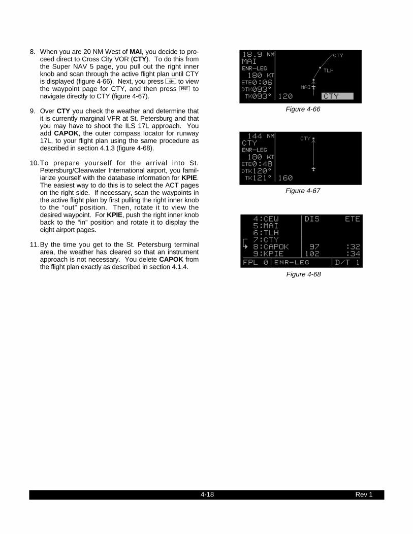
4-18 Rev 1
8. When you are 20 NM West of MAI, you decide to pro-ceed direct to Cross City VOR (CTY). To do this fromthe Super NAV 5 page, you pull out the right innerknob and scan through the active flight plan until CTYis displayed (figure 4-66). Next, you press D to viewthe waypoint page for CTY, and then press E tonavigate directly to CTY (figure 4-67).
9. Over CTY you check the weather and determine thatit is currently marginal VFR at St. Petersburg and thatyou may have to shoot the ILS 17L approach. Youadd CAPOK, the outer compass locator for runway17L, to your flight plan using the same procedure asdescribed in section 4.1.3 (figure 4-68).
10.To prepare yourself for the arrival into St.Petersburg/Clearwater International airport, you famil-iarize yourself with the database information for KPIE.The easiest way to do this is to select the ACT pageson the right side. If necessary, scan the waypoints inthe active flight plan by first pulling the right inner knobto the “out” position. Then, rotate it to view thedesired waypoint. For KPIE, push the right inner knobback to the “in” position and rotate it to display theeight airport pages.
11.By the time you get to the St. Petersburg terminalarea, the weather has cleared so that an instrumentapproach is not necessary. You delete CAPOK fromthe flight plan exactly as described in section 4.1.4.
18.9 oq MAI | xy-«} | 180 uv áà0:06| ûü093^| †ü093^|120 CTY
MAI
TLH
CTY
Figure 4-66
144 oq CTY | xy-«} | 180 uv áà0:48| ûü120^| †ü121^|160
CTY
Figure 4-67
4:CEW |DIS ETE 5:MAI | 6:TLH | ; 7:CTY | < 8:CAPOK | 97 :32 9:KPIE |102 :34 FPL 0 enr-leg D/T 1
Figure 4-68

5-1
5.1 TRIP PLANNING
There are seven Trip Planning pages (TRI) that can bedisplayed on the left side of the screen. The KLN 90Ballows three kinds of trip planning. The TRI 1 and TRI 2pages team together to provide trip planning from yourpresent position to any waypoint of your choice. TheTRI 3 and TRI 4 pages provide trip planning betweenany two waypoints, and the TRI 5 and TRI 6 pages pro-vide an analysis of any of the 26 flight plans (FPL 0,FPL 1, FPL 2, ..., FPL 25) stored in the Flight Planpages. The TRI 0 page is used to enter estimates ofyour true airspeed and of the winds so that the KLN 90Bcan perform wind triangle calculations for use on theother Trip Planning pages.
Data entered on any of the Trip Planning pages has noeffect on navigation data provided on any Navigation(NAV) or Flight Plan (FPL) pages. You may perform tripplanning without disturbing ongoing navigation.
NOTE: The Trip Planning pages rely on pilot enterableinputs for true airspeed, groundspeed, and fuel flow.These pages do not utilize inputs from fuel flow or airdata sensors. Fuel management and air data pages arediscussed in section 5.10 and 5.11.
NOTE: Areas of special use airspace are displayed onthe Trip Planning pages without regard to altitude.
Rev 1
CHAPTER 5 - LEVEL 3 OPERATION
the Trip Planning pages, the Calculator pages, andother features that you may find very beneficial and con-venient to use in your flying.
This is the third of four chapters specifically dealing withoperating the KLN 90B. In this chapter you will learn touse many of the supplementary features of the KLN90B. These include such things as the Advisory VNAV,

5-2
5.1.1 The Trip Planning 0 Page (TRI 0)If desired, you may enter the aircraft’s true airspeed(TAS) and the winds aloft on the TRI 0 page so that thisinformation is utilized on the other Trip Planning pages.The KLN 90B uses the TAS and winds entered on theTRI 0 page to calculate your estimated groundspeed forspecific trip planning routes you enter on the other TripPlanning pages.
To enter data on the TRI 0 page:
1. Select the TRI 0 page on the left side (figure 5-1).
2. Press the left C to turn on the left cursor function.
3. Enter the aircraft’s true airspeed by using the leftouter knob to move the cursor to the desired locationand the left inner knob to select each individual digit(figure 5-2).
4. Rotate the left outer knob clockwise to position thecursor over the first two digits of the wind direction(figure 5-3).
5. Turn the left inner knob to select the first two digits ofthe wind direction (figure 5-4).
6. Rotate the left outer knob one step clockwise to posi-tion the cursor over the last digit of the wind direc-tion, and then use the left inner knob to complete thewinds direction entry.
7. Enter the wind speed by using the left outer knob tomove the cursor and the left inner knob to selecteach individual digit (figure 5-5).
8. Press the left C to turn off the left cursor function.
Let’s say you enter a TAS of 200 knots and winds of180 degrees at 25 knots on the TRI 0 page. If youentered two waypoints on the TRI 3 page (trip planningbetween two waypoints) and the bearing from the firstwaypoint you entered to the second was 180 degrees,then the TRI 3 page would contain a groundspeed ofabout 175 knots. The reason we say about 175 knotsis that the direction of the winds you enter are relative totrue North and the bearing displayed is relative to mag-netic North. Remember that winds information you getfrom a Flight Service Station or from an ATC facility isalways provided relative to true North. On the TRI 5and TRI 6 pages (trip planning for a flight plan), thewinds are applied to each individual leg of the flightplan.
Rev 1
Figure 5-3 Figure 5-4
TRIP PLAN | ESTIMATES | |TAS: 200kt|WIND: 210^%| 018kt| CRSR
TRIP PLAN | ESTIMATES | | TAS: 200kt| WIND: 180^%| 018kt| CRSR
Figure 5-5
TRIP PLAN | ESTIMATES | | TAS: 200kt| WIND: 180^%| 025kt| CRSR
Figure 5-1 Figure 5-2
TRIP PLAN | ESTIMATES | | TAS: 150kt| WIND: 210^%| 018kt| TRI 0
TRIP PLAN | ESTIMATES | | TAS: 200kt| WIND: 210^%| 018kt| CRSR

5-3
5.1.2 The Trip Planning 1 And Trip Planning 2 Pages(TRI 1 and TRI 2)
The TRI 1 and TRI 2 pages allow trip planning from yourpresent position to any waypoint of your choice. Unlikethe other Trip Planning pages, in order to utilize the TRI1 and TRI 2 pages, the KLN 90B must either be receiv-ing GPS signals sufficient to be in the NAV ready statusor the KLN 90B must be in the take-home mode.
The TRI 1 page provides estimates of distance, esti-mated time enroute, bearing, and fuel requirements.The TRI 2 page displays the minimum enroute safe alti-tude (ESA) and any areas of special use airspace thatlay between your present position and the selected way-point. The TRI 1 and TRI 2 pages are useful, for exam-ple, while you are airborne and wish to determine dis-tance, time, fuel, and altitude requirements direct to analternate location.
NOTE: Prior to using the TRI 1 and TRI 2 pages whilethe KLN 90B is in the take-home mode, use the SET 1page to enter your present position. See section 3.6,“INITIALIZATION AND TIME TO FIRST FIX”, for anexplanation of entering position on the SET 1 page.
For the following example let’s say the aircraft is locatedover Battle Mountain VOR (BAM) enroute to LakeTahoe and you wish to perform trip planning back toSalt Lake City International airport (KSLC). To performtrip planning on the TRI 1 and TRI 2 pages:
1. Use the left outer knob to select the TRI type pageson the left side.
2. Rotate the left inner knob to display the TRI 1 pageon the left side (figure 5-6).
3. Press the left C to turn on the left cursor function.The cursor will be over the waypoint identifier at thetop of the page.
4. Use the left inner and outer knobs to enter the identi-fier of the selected waypoint (figure 5-7).
5. Press E to view the waypoint page for the selectedwaypoint on the right side.
6. Press E again to acknowledge the waypoint page.The distance, bearing, and estimated time enrouteare now displayed (figure 5-8).
If you entered true airspeed and wind velocity informa-tion on the TRI 0 page, the groundspeed displayed is aresult of those inputs applied to the direction of flightspecified on the TRI 1 page. You may also enter anygroundspeed you desire by using the left outer knob toposition the cursor over each digit of the groundspeedand using the left inner knob to select each individualdigit.
Rev 1
Figure 5-6
P.POS-KLAX | 404nm 175^| 175kt 2:18| FF: 00028.0| RES:00025.0| F REQ 89.5| TRI 1
Figure 5-7
P.POS-KSLC | 404nm 175^| 175kt 2:18| FF: 00028.0| RES:00025.0| F REQ 89.5| CRSR
Figure 5-8
P.POS-KSLC | 226nm 070^| 200kt 1:08| FF: 00028.0| RES:00025.0| F REQ 56.5| CRSR

5-4
7. You can also calculate an estimate of the fuelrequired to the selected waypoint. Turn the left outerknob to position the cursor over the appropriate firstdigit adjacent to fuel flow (FF).
8. Use the left inner and outer knobs as before to enterthe aircraft’s rate of fuel flow. The unit (gallons,pounds, etc.) is not important as long as you areconsistent (figure 5-9).
9. Use the left inner and outer knobs to enter theamount of reserve fuel (RES) desired when youreach the selected waypoint (figure 5-10). The esti-mated amount of fuel required (F REQ) to fly to theselected waypoint with the specified reserve is nowdisplayed. Entering the fuel flow and reserve fuel onthe TRI 1 page also inputs this same information onthe TRI 3 and TRI 5 pages.
10.Press the left C to turn off the left cursor function.
11.Select the TRI 2 page (figure 5-11). The minimumenroute safe altitude (ESA)) and a listing of areas ofspecial use airspace along the route are displayed.If all of the areas of special use airspace won’t fit onone page, there will be multiple TRI 2 pages indi-cated by TRI+2.
Rev 1
Figure 5-11
P.POS-KSLC | ESA 14100ft| LUCIN C | MOA | SALT LAKE | CITY CL B | TRI 2
Figure 5-9
P.POS-KSLC | 226nm 070^| 200kt 1:08| FF: 00032.0| RES:00025.0| F REQ 61.0| CRSR
Figure 5-10
P.POS-KSLC | 226nm 070^| 200kt 1:08| FF: 00032.0| RES:00032.0| F REQ 68.0| CRSR
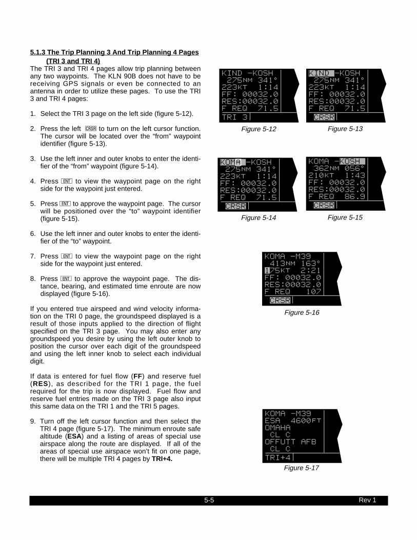
5-5
5.1.3 The Trip Planning 3 And Trip Planning 4 Pages(TRI 3 and TRI 4)
The TRI 3 and TRI 4 pages allow trip planning betweenany two waypoints. The KLN 90B does not have to bereceiving GPS signals or even be connected to anantenna in order to utilize these pages. To use the TRI3 and TRI 4 pages:
1. Select the TRI 3 page on the left side (figure 5-12).
2. Press the left C to turn on the left cursor function.The cursor will be located over the “from” waypointidentifier (figure 5-13).
3. Use the left inner and outer knobs to enter the identi-fier of the “from” waypoint (figure 5-14).
4. Press E to view the waypoint page on the rightside for the waypoint just entered.
5. Press E to approve the waypoint page. The cursorwill be positioned over the “to” waypoint identifier(figure 5-15).
6. Use the left inner and outer knobs to enter the identi-fier of the “to” waypoint.
7. Press E to view the waypoint page on the rightside for the waypoint just entered.
8. Press E to approve the waypoint page. The dis-tance, bearing, and estimated time enroute are nowdisplayed (figure 5-16).
If you entered true airspeed and wind velocity informa-tion on the TRI 0 page, the groundspeed displayed is aresult of those inputs applied to the direction of flightspecified on the TRI 3 page. You may also enter anygroundspeed you desire by using the left outer knob toposition the cursor over each digit of the groundspeedand using the left inner knob to select each individualdigit.
If data is entered for fuel flow (FF) and reserve fuel(RES), as described for the TRI 1 page, the fuelrequired for the trip is now displayed. Fuel flow andreserve fuel entries made on the TRI 3 page also inputthis same data on the TRI 1 and the TRI 5 pages.
9. Turn off the left cursor function and then select theTRI 4 page (figure 5-17). The minimum enroute safealtitude (ESA) and a listing of areas of special useairspace along the route are displayed. If all of theareas of special use airspace won’t fit on one page,there will be multiple TRI 4 pages by TRI+4.
Rev 1
Figure 5-12
KOMA -M39 | 413nm 163^| 175kt 2:21| FF: 00032.0| RES:00032.0| F REQ 107| CRSR
Figure 5-13
KIND -KOSH | 275nm 341^| 223kt 1:14| FF: 00032.0| RES:00032.0| F REQ 71.5| TRI 3
Figure 5-14
KIND -KOSH | 275nm 341^| 223kt 1:14| FF: 00032.0| RES:00032.0| F REQ 71.5| CRSR
Figure 5-15
KOMA -KOSH | 275nm 341^| 223kt 1:14| FF: 00032.0| RES:00032.0| F REQ 71.5| CRSR
Figure 5-16
KOMA -KOSH | 362nm 056^| 210kt 1:43| FF: 00032.0| RES:00032.0| F REQ 86.9| CRSR
Figure 5-17
KOMA -M39 | ESA 4600ft| OMAHA | CL C | OFFUTT AFB | CL C | TRI[4

5-6 Rev 1
5.1.4 The Trip Planning 5 And Trip Planning 6 Pages(TRI 5 and TRI 6)
The TRI 5 and TRI 6 pages are used to do trip planningfor any one of the previously entered flight plans (FPL 0,FPL 1, FPL 2, ..., FPL 25). The KLN 90B does not haveto be receiving GPS signals or even be connected to anantenna in order to utilize these pages. To use the TRI5 and TRI 6 pages:
1. Select the TRI 5 page on the left side (figure 5-18).
2. Press the left C to turn on the left cursor function.The cursor will be located over the flight plan num-ber.
3. Rotate the left inner knob to select the desired flightplan to be analyzed (figure 5-19). The first and lastwaypoints in the selected flight plan are displayed onthe second line. The distance and estimated timeenroute are also displayed. There is no bearing dis-play since the flight plan can have up to 30 way-points which creates 29 flight plan legs.
If you entered true airspeed and wind velocity informa-tion on the TRI 0 page, the groundspeed displayed isthe average groundspeed for the flight plan. It is theresult of the true airspeed and wind velocity entered onthe TRI 0 page applied to each leg of the flight plan.You may also enter any groundspeed you desire byusing the left outer knob to position the cursor over eachdigit of the groundspeed and using the left inner knob toselect each individual digit.
If data is entered for fuel flow (FF) and reserve fuel(RES), as described for the TRI 1 page, the fuelrequired for the trip is now displayed. Fuel flow andreserve fuel entries made on the TRI 5 page also inputthis same data on the TRI 1 and the TRI 3 pages.
4. Turn off the left cursor function and then select theTRI 6 page (figure 5-20). The minimum enroute safealtitude (ESA) and a listing of areas of special useairspace along the flight plan route are displayed. Ifall of the areas of special use airspace won’t fit onone page, there will be multiple TRI 6 pages indi-cated by TRI+6.
Figure 5-18
FP 3 463nm| K34 -KAPA | 202kt 2:17| FF: 00032.0| RES:00032.0| F REQ 105| TRI 5
Figure 5-19
FP 5 692nm| KDEN -KSAT | 177kt 3:53| FF: 00032.0| RES:00032.0| F REQD 156| CRSR
Figure 5-20
FP 5 | ESA 14700ft| DENVER | CL B | PINON CANYO| N | TRI[6

5-7 Rev 1
5.2 ADVISORY VNAV OPERATION
The KLN 90B’s vertical navigation feature (VNAV)allows you to program a descent or ascent path, andthen provides you with an advisory altitude to fly that willprovide guidance along the vertical path. For example,you can program the VNAV to provide descent guidanceso that you arrive at your active waypoint or a waypointin the active flight plan at an altitude that you specify.The KLN 90B will alert you of when to start the descent,and display the advisory altitudes to fly throughout thedescent.
5.2.1 VNAV For Direct To OperationThe Navigation 4 (NAV 4) page is used to program theKLN 90B for vertical navigation. The following examplewill be used to illustrate how to use the VNAV feature.You are using the KLN 90B to fly direct to your destina-tion airport, Dubuque Municipal airport (KDBQ) locatedin Dubuque, Iowa. You are presently about 65 nm Westof Dubuque, flying at 7500 feet MSL (figure 5-21). Youdesire to use the VNAV to provide vertical guidance toDubuque’s traffic pattern altitude of 1900 feet MSL.
1. Select the NAV 4 page on either side of the screen(figure 5-22). You can select the NAV 4 page eitherby using the knobs or by pressing A to bring up theNAV 4 page on the right side and the ALT page onthe left. The aircraft’s actual altitude is displayed inthe IND field. If the displayed altitude is incorrect it isprobably because you have not recently updated theKLN 90B’s altimeter baro setting on the ALT page(see section 3.15).
NOTE: There may be some difference (less than 100feet) between the indicated altitude (IND) and the air-craft’s actual altitude if the altitude input to the KLN 90Bis from an altitude encoder because these encodersonly provide altitude in 100 foot increments.
The identifier for the active waypoint (KDBQ) is auto-matically displayed on the NAV 4 page. Prior to pro-gramming a VNAV operation, the top of the page dis-plays that the VNAV is inactive (VNV INACTV).
2. Press the appropriate C button to turn on the cur-sor function if it is not already on (figure 5-23).
3. Enter the desired altitude of 1900 feet in the SELfield. The outer knob is used to move the cursor andthe inner knob is used to select the digits. The alti-tude may be entered in 100 foot increments (figure 5-24).
NOTE: If the KLN 90B does not have an altitude input,the IND and SEL fields will be labeled FR (from) and TOrespectively. The aircraft’s present altitude must beentered into the FR field and the desired altitude into theTO field.
Figure 5-21
$=KDBQ DIS 64.8nm ETE :27 GS 145kt BRG 094^ NAV 1 enr-leg NAV 1
Figure 5-22
$=KDBQ |VNV INACTV +++++Â+++++| DIS 64.8nm|IND 07500ft GS 145kt|SEL:00000ft ETE :27|KDBQ :-00nm BRG 094^|ANGLE:-0.8^ NAV 1 enr-leg NAV 4
Figure 5-23
|VNV INACTV | |IND 07500ft |SEL:00000ft |KDBQ :-00nm |ANGLE:-0.8^ CRSR
Figure 5-24
|VNV INACTV | |IND 07500ft |SEL:01900ft |KDBQ :-00nm |ANGLE:-0.8^ CRSR

5-8 Rev 1
Figure 5-28
|VNV 7500ft | |IND 07500ft |SEL:01900ft |KDBQ :-02nm |ANGLE:-1.8^ NAV 4
4. Use the outer knob to move the cursor to the offsetfield adjacent to the active waypoint identifier.Entering an offset allows you to reach the desiredaltitude a specified distance before reaching the way-point. In this example you desire to reach traffic pat-tern altitude two nautical miles prior to the airport,which allows sufficient time to slow down and pre-pare for the landing. Enter an offset of 2 nm (figure5-25).
Notice that the bottom of the NAV 4 page now displaysan angle. If you wish to start your descent now usingthe displayed descent angle, use the outer knob to posi-tion the cursor over the ANGLE field (figure 5-26).VNAV operation is initiated by bringing the cursor overthe ANGLE field. Or, by leaving the cursor off of theANGLE field, you may watch the VNAV angle increaseas you fly toward your waypoint. When the desiredangle is reached, position the cursor over the ANGLEfield and VNAV will commence. When VNAV begins,the top of the page displays an advisory altitude. Juststart a rate of descent so that the aircraft’s altimetermatches the advisory altitude.
A better way yet to initiate VNAV is to program a desiredangle to use for the descent. If you are not sure what asuitable descent angle is, use the CAL 4 page to calcu-late one for you. The CAL 4 page is described in sec-tion 5.3.4. After a little experience using the VNAV fea-ture, you will soon learn what angles to use for your nor-mal speeds and rates of descent. To program adescent angle:
5. Use the outer knob to move the cursor to theANGLE field, and then enter the desired descentangle (figure 5-27). If the time to begin your descentis greater than ten minutes, VNV ARMED will nowbe displayed on the top line of the NAV 4 page. Ifthe time is less than ten minutes, the top line dis-plays a countdown to the time to begin the descent.
6. Return to any desired page for now. If you got to theNAV 4 page by pressing A, press Aonce againto return to the pages previously in view. If you gotto the NAV 4 page using the inner and outer knobs,press C to turn off the cursor function and thenuse the inner and outer knobs to select the desiredpage. Approximately 90 seconds before the time tobegin descent, the message prompt will flash. Whenyou view the Message page, it will display “VNAVALERT”. This is notification for you to view the NAV4 page because it is getting close to the time tobegin your descent.
7. When the countdown reaches 0:00, the time will bereplaced with an advisory altitude (figure 5-28).Begin your rate of descent so that the altitude dis-played on your altimeter matches the advisory alti-tude.
Figure 5-25
|VNV INACTV | |IND 07500ft |SEL:01900ft |KDBQ :-02nm |ANGLE:-0.8^ CRSR
Figure 5-26
|VNV 7500ft | |IND 07500ft |SEL:01900ft |KDBQ :-02nm |ANGLE:-0.8^ CRSR
Figure 5-27
VNV ANGLE |VNV IN 8:53 | GS: 160kt|IND 07500ft FPM: 0500|SEL:01900ft ANGLE 1.8^|KDBQ :-02nm |ANGLE:-1.8^ CAL 4 enr-leg CRSR

5-9 Rev 1
5.2.2 VNAV For Flight Plan OperationUsing the vertical navigation function when flying via aflight plan is virtually the same as for the previous DirectTo example. The NAV 4 page will initially contain theidentifier for the active “to” waypoint in the flight plan.You may program the vertical ascent or descent refer-encing this waypoint or you may enter the identifierfor any waypoint in the active flight plan which isstill in front of the aircraft’s position. When anothervalid waypoint in the flight plan is entered on the NAV 4page, the aircraft’s lateral flight path is not altered. Thismeans that you may program a vertical flight path hav-ing an ascent or descent point that begins prior to theflight plan leg containing the selected VNAV waypoint.
5.2.3 VNAV From the Super NAV 5 PageThe Super NAV 5 page can be configured to display theVNAV status. This means that you will not have tochange pages to see what altitude you should be at.You will still need to set up the VNAV problem by usingthe NAV 4 page as described in section 5.2.1. To usethe Super NAV 5 page to view the VNAV status use thefollowing steps.
1. Set up the VNAV situation from the NAV 4 page.
2. Turn to the Super NAV 5 page by selecting NAV 5 onboth sides of the display.
3. Turn on the left cursor and rotate the left outer knobcounter-clockwise until the cursor is over the thirdline from the bottom of the display (figure 5-28a).
4. Rotate the left inner knob until “VNAV” is displayed(figure 5-28b). Turn the left cursor off by pressing theleft C.
5. The Super NAV 5 page will now display the VNAVstatus. If the VNAV problem has not been definedyet, then V OFF will be displayed. If the time to startVNAV operation is greater than 10 minutes then V ARM is displayed. When the time to VNAVoperation is less than 10 minutes then the SuperNAV 5 page wil l display the time unti l VNAVoperation will start. For example, V 4:53 would bedisplayed if the time until VNAV operation is 4minutes and 53 seconds. If the VNAV function hasstarted and is suggesting an altitude then the SuperNAV 5 display will display this altitude. For exampleV 4300 would be displayed if the suggested altitudewas 4300 feet.
NOTE: If you used the CAL 4 page to determine theascent/descent angle, the aircraft’s groundspeed dur-ing the ascent/descent should match that entered onthe CAL 4 page. If a different groundspeed is actu-ally flown, a different rate of ascent/descent from theone entered on the CAL 4 page will be required.
Figure 5-28a
25.5 oq KPIE | xy-«} | 201 uv ETE | ûü172^| †ü173^|30
KPIE
24.6 oq KPIE | xy-«} | 201 uv VNAV | ûü172^| †ü173^|30
KPIE
Figure 5-28b
CAUTION: Advisory VNAV operation will only beaccurate if the altimeter baro correction is keptupdated. If advisory VNAV is used, it is a good ideato update the altimeter baro set on the ALT pageeach time you make a change to the aircraft’saltimeter setting.

5-10 Rev 1
5.3 CALCULATOR PAGES
There are seven Calculator pages which may be used tocalculate a variety of flight related information such aspressure and density altitude, true airspeed, winds aloft,VNAV angle, and time zone conversions. The Calculatorpages allow you to make “what if” calculations for condi-tions other than the present situation. Therefore, theCalculator pages rely on you to make manual inputs of airdata parameters such as altitude and true airspeed evenif the KLN 90B is interfaced to air data sensors. If theKLN 90B is interfaced with a compatible air data system,the Other 9 and Other 10 (OTH 9 and OTH 10) pagesdisplay the air data information directly.
5.3.1 The Calculator 1 Page (CAL 1)The CAL 1 page is used to determine pressure altitudeand density altitude. To calculate these values:
1. Display the CAL 1 page on the left side (figure 5-29).
2. Press the left C to turn on the left cursor function.
3. Enter the altitude indicated on the aircraft’s altimeter(IND) to the nearest hundred feet by using the leftouter knob to move the cursor to the desired positionand the left inner knob to select each digit (figure 5-30).
4. Use the left outer knob to move the cursor to the firstBARO position, and then enter the current altimetersetting by using the left inner and outer knobs (figure5-31). The pressure altitude is now displayed (PRS).
NOTE: The SET 7 page (figure 5-32) is used to selectwhether the altimeter setting on the CAL 1 page is madein inches of Mercury (”) or millibars (MB). To change thealtimeter setting from inches to millibars, or vice versa,select the SET 7 page, press the left C, and rotate theleft inner knob to make your selection. When finished,press the left C to turn off the cursor function.
NOTE: Some areas of the world use hectopascals as abarometric unit. Hectopascals are numerically the sameas millibars so choose millibars as the barometric unit inthese areas.
5. Use the left outer knob to move the cursor to the firstTEMP position, and then enter the outside air temper-ature (degrees C) by using the left inner and outerknobs (figure 5-33). The first digit of the temperatureis either “0” if the temperature is above zero or “-” ifthe temperature is below zero. For maximum accu-racy, the static air temperature should be entered.This is the temperature of air without the effect ofheating due to movement through the air. For the air-speeds of most piston aircraft, the difference betweenstatic air temperature and the observed air tempera-ture (or “total air temperature”) is negligible.
Figure 5-29
ALTITUDE | IND:09000ft| BARO:29.92"| PRS 9000ft| TEMP: 005^C| DEN 9900ft| CAL 1
Figure 5-30
ALTITUDE | IND:08500ft| BARO:29.92"| PRS 8500ft| TEMP: 005^C| DEN 9300ft| CRSR
Figure 5-31
ALTITUDE | IND:08500ft| BARO:30.04"| PRS 8400ft| TEMP: 005^C| DEN 9200ft| CRSR
Figure 5-32
BARO SET | UNITS | | " | | INCHES | SET 7
Figure 5-33
ALTITUDE | IND:08500ft| BARO:30.04"| PRS 8400ft| TEMP: 006^C| DEN 9300ft| CRSR

5-11 Rev 1
The density altitude (DEN) is now displayed.
6. Press the left C to turn off the left cursor function.
NOTE: If a compatible air data system is interfaced to theKLN 90B the Other 10 (OTH 10) page displays pressureand density altitude directly for the present conditions.
5.3.2 The Calculator 2 Page (CAL 2)The CAL 2 page is used to determine the true airspeed(TAS) of the aircraft. To calculate the true airspeed:
1. Select the CAL 2 page on the left side (figure 5-34).
2. Press the left C to turn on the left cursor function.
3. Enter the aircraft’s calibrated airspeed by using theleft inner and outer knobs (figure 5-35). If the cali-brated airspeed isn’t known, use the indicated air-speed. For most aircraft the difference between thecalibrated airspeed and the indicated airspeed issmall at cruise airspeeds.
4. Use the left outer knob to move the cursor to the firstALT position, and then enter the aircraft’s indicatedaltitude using the left inner and outer knobs. If theindicated altitude was previously entered on the CAL1 page, it will already be displayed.
5. Turn the left outer knob to move the cursor to thefirst BARO position and then enter the currentaltimeter setting using the left inner and outer knobs.If the altimeter setting was made on the CAL 1 page,it will already be displayed. The SET 7 page is usedto select between making the altimeter setting ininches of mercury (”) or millibars (MB).
6. Rotate the left outer knob to move the cursor to thefirst TEMP position, and then enter the outside airtemperature (degrees C) by using the left outer andinner knobs (figure 5-36). The first digit of the tem-perature is either “0” if the temperature is abovezero or “-” if the temperature is below zero. For max-imum accuracy, the “total air temperature” should beentered. This is the temperature of air including theeffect of heating due to movement through the air.The temperature read on a standard outside air tem-perature gauge found on most piston aircraft is “totalair temperature”. Note that because of the two typesof temperature, a temperature entry made on theCAL 1 page is not transferred to the CAL 2 page.
The true airspeed (TAS) is now displayed.
7. Press the left C to turn off the left cursor function.
NOTE: If a compatible air data system is interfaced tothe KLN 90B, true airspeed (TAS) is displayed directlyon the Other 9 (OTH 9) page for the present conditions.
Figure 5-34
TAS | CAS: 139kt| ALT:08500ft| BARO:30.04"| TEMP: 002^C| TAS 158kt| CAL 2
Figure 5-35
TAS | CAS: 144kt| ALT:08500ft| BARO:30.04"| TEMP: 002^C| TAS 163kt| CRSR
Figure 5-36
TAS | CAS: 144kt| ALT:08500ft| BARO:30.04 | TEMP: 006^C| TAS 164kt| CRSR

5-12 Rev 1
5.3.3 The Calculator 3 Page (CAL 3)The CAL 3 page is used to determine the present winddirection and speed. In addition, the headwind or tailwindcomponent of the wind is displayed. To calculate thesevalues:
1. Select the CAL 3 page on the left side (figure 5-37).
2. Press the left C to turn on the left cursor function.
3. Enter the aircraft’s true airspeed (TAS) by using theleft inner and outer knobs. If the CAL 2 page was pre-viously used to calculate true airspeed, it will alreadybe displayed.
4. Use the left outer knob to move the cursor to the firstHDG position, and then enter the aircraft’s headingusing the left inner and outer knobs (figure 5-38). Theheadwind (HDWND) or tailwind (TLWND) and thewind direction and speed are now displayed. Thewind direction is relative to true North.
NOTE: The wind calculations are only correct when youhave entered the correct aircraft heading and true air-speed. Make sure to re-enter new values if you changeairspeed or heading.
5. Press the left C to turn off the left cursor function.
NOTE: If the KLN 90B is interfaced with a compatiblesource of heading information, line three of the CAL 3page is blank. Heading is then automatically input andused in the wind calculation displayed on the CAL 3 page.If the KLN 90B is interfaced with a compatible air datasystem in addition to a compatible heading source, theOther 9 (OTH 9) page displays wind information directly.
5.3.4 The Calculator 4 Page (CAL 4)The CAL 4 page is used to determine vertical navigationdescent/ascent angles to use on the NAV 4 page. To cal-culate the required angle:
1. Select the CAL 4 page on the left side (figure 5-39).
2. Press the left C to turn on the left cursor function.
3. Use the left inner and outer knobs to enter what theaircraft’s groundspeed will be during the descent orascent (figure 5-40).
4. Turn the left outer knob to move the cursor to the firstFPM position, and then enter the desired rate ofdescent or ascent (in feet per minute) using the leftinner and outer knobs (figure 5-41). Thedescent/ascent angle is now displayed.
In addition, you may enter an angle and determinewhat rate of descent or ascent will be required for theselected combination of groundspeed and angle.
5. Press the left C to turn off the left cursor function.
Figure 5-37
WIND | TAS 164kt| HDG 000^| HDWND 12kt| WIND 340^%| 16kt| CAL 3
Figure 5-38
WIND | TAS 164kt| HDG 005^| HDWND 11kt| WIND 350^%| 15kt| CRSR
Figure 5-39
VNV ANGLE | | GS: 175kt| FPM: 0800| ANGLE: 2.6^| | CAL 4
Figure 5-40
VNV ANGLE | | GS: 160kt| FPM: 0800| ANGLE: 2.8^| | CRSR
Figure 5-41
VNV ANGLE | | GS: 160kt| FPM: 0500| ANGLE: 1.8^| | CRSR

5-13 Rev 1
5.3.5 The Calculator 5 Page (CAL 5)The CAL 5 page is used to perform two types of conver-sions: 1) Degrees Centigrade (C) to degreesFahrenheit (F) and vice versa and 2) knots (KT) to milesper hour (MPH) and vice versa. To use the CAL 5page:
1. Display the CAL 5 page on the left side (figure 5-42).
2. Press the left C to turn on the left cursor function.
3. To convert degrees C to degrees F, use the leftouter knob to position the cursor over the appropri-ate Centigrade digits and use the left inner knob toselect the desired values of temperature. When thedesired temperature in degrees C is selected, thecorresponding temperature in degrees F is displayed(figure 5-43).
To convert degrees F to degrees C, use the leftouter knob to position the cursor over the appropri-ate Fahrenheit digits and use the left inner knob toselect the desired values of temperature. When thedesired temperature in degrees F is selected, thecorresponding temperature in degrees C is dis-played.
To convert knots to miles per hour, use the left outerknob to position the cursor over the appropriateknots digits and use the left inner knob to select thedesired values of speed. When the desired speed inknots is selected, the corresponding speed in milesper hour is displayed (figure 5-44).
To convert miles per hour to knots, use the left outerknob to position the cursor over the appropriate MPHdigits and use the left inner knob to select thedesired values of speed. When the desired speed inmiles per hour is selected, the corresponding speedin knots is displayed.
4. Press the left C to turn off the left cursor function.
Figure 5-42
TEMP/SPEED | 000^C | 032^F | | 100kt | 115mph | CAL 5
Figure 5-43
TEMP/SPEED | 025^C | 077^F | | 100kt | 115mph | CRSR
Figure 5-44
TEMP/SPEED | 025^C | 077^F | | 145kt | 167mph | CRSR
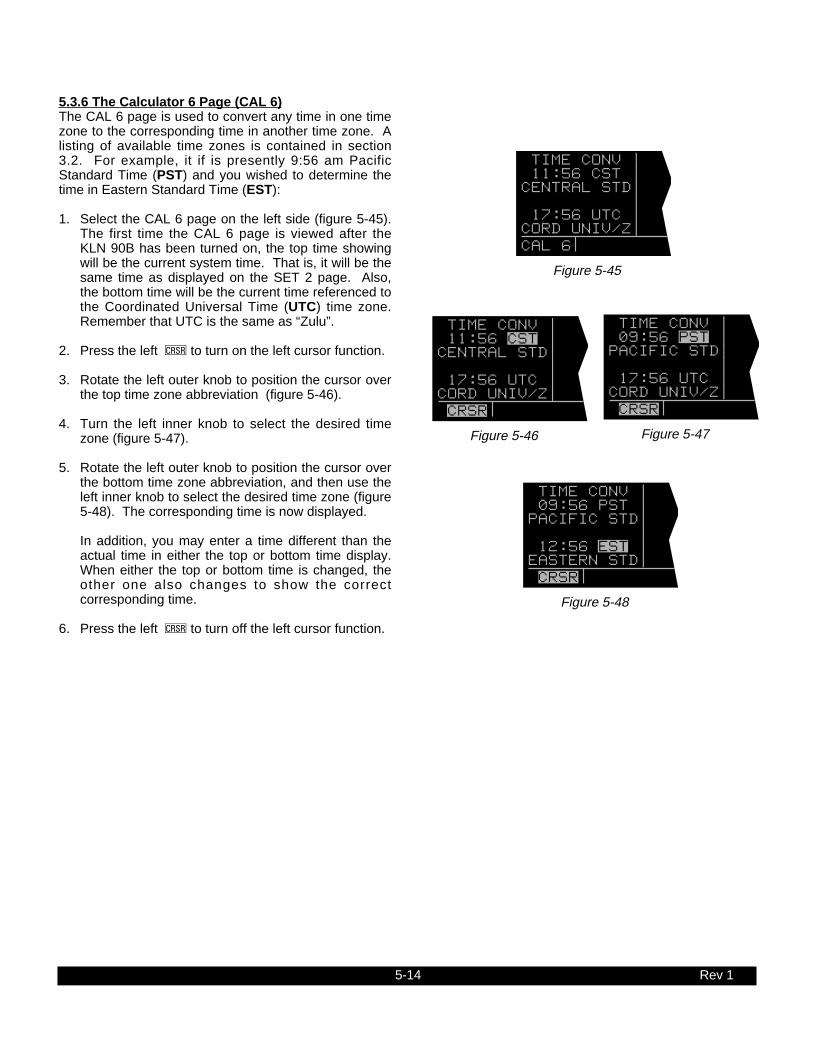
5-14 Rev 1
5.3.6 The Calculator 6 Page (CAL 6)The CAL 6 page is used to convert any time in one timezone to the corresponding time in another time zone. Alisting of available time zones is contained in section3.2. For example, it if is presently 9:56 am PacificStandard Time (PST) and you wished to determine thetime in Eastern Standard Time (EST):
1. Select the CAL 6 page on the left side (figure 5-45).The first time the CAL 6 page is viewed after theKLN 90B has been turned on, the top time showingwill be the current system time. That is, it will be thesame time as displayed on the SET 2 page. Also,the bottom time will be the current time referenced tothe Coordinated Universal Time (UTC) time zone.Remember that UTC is the same as “Zulu”.
2. Press the left C to turn on the left cursor function.
3. Rotate the left outer knob to position the cursor overthe top time zone abbreviation (figure 5-46).
4. Turn the left inner knob to select the desired timezone (figure 5-47).
5. Rotate the left outer knob to position the cursor overthe bottom time zone abbreviation, and then use theleft inner knob to select the desired time zone (figure5-48). The corresponding time is now displayed.
In addition, you may enter a time different than theactual time in either the top or bottom time display.When either the top or bottom time is changed, theother one also changes to show the correctcorresponding time.
6. Press the left C to turn off the left cursor function.
Figure 5-46
TIME CONV | 11:56 CST | CENTRAL STD| | 17:56 UTC | CORD UNIV/Z| CRSR
Figure 5-47
TIME CONV | 09:56 PST | PACIFIC STD| | 17:56 UTC | CORD UNIV/Z| CRSR
Figure 5-48
TIME CONV | 09:56 PST | PACIFIC STD| | 12:56 EST | EASTERN STD| CRSR
Figure 5-45
TIME CONV | 11:56 CST | CENTRAL STD| | 17:56 UTC | CORD UNIV/Z| CAL 6

5-15
5.3.7 The Calculator 7 Page (CAL 7)The CAL 7 page is used to display the times of sunriseand sunset for any waypoint in the published or userdatabase. It can do this for any date you desire untilDecember 31, 2087. Amazing you say! Yes, but it’strue! To use the CAL 7 page:
1. Select the CAL 7 page on the left side (figure 5-49).The first time the CAL 7 page is selected after theKLN 90B is turned on, the waypoint identifier defaultsto the current destination, the date defaults to the cur-rent date, and the time zone defaults to the systemtime zone. Each of these three items may, however,be changed. The sunrise and sunset are displayed atthe bottom of the page.
NOTE: The time zone initially displayed is the systemtime zone. This is the same as the one on the SET 2page. Note that the time zone displayed may not beappropriate for the waypoint shown. For example, thewaypoint shown could be KLAX and the time zone maybe Eastern Standard Time (EST). Make sure you selectthe appropriate time zone for the displayed waypoint.
2. Press the left C to turn on the left cursor function.
3. If desired, select another waypoint identifier usingthe left inner and outer knobs. Press E to view thewaypoint page for the waypoint entered. Press Eagain to approve the waypoint page (figure 5-50).
4. If desired, select another date using the left innerand outer knobs. You must press E to enter thedate (figure 5-51).
5. If desired, select another time zone. The sunriseand sunset times for the selected waypoint, date,and time zone are now displayed (figure 5-52).
6. Press the left C to turn off the left cursor function.
Rev 1
Figure 5-49
SUNRISE/SET| KORD | 03 MAR 89| CST| RISE 06:24| SET 17:43| CAL 7
Figure 5-50
SUNRISE/SET| KATL | 03 MAR 89| CST| RISE 06:04| SET 17:35| CRSR
Figure 5-51
SUNRISE/SET| KATL | 10 MAR 89| CST| RISE 05:55| SET 17:41| CRSR
Figure 5-52
SUNRISE/SET| KATL | 10 MAR 89| EST| RISE 06:55| SET 18:41| CRSR

5-16 Rev 1
Figure 5-55
| FARM | | | |N 42^26.91' |W 91^11.22' |APT 1
5.4 USER-DEFINED WAYPOINTS
Up to 250 user-defined waypoints may be created.These waypoints may be defined as a user-defined air-port, VOR, NDB, or intersection. If the waypoint doesn’tfit into one of these categories, it may be defined as asupplemental (SUP) waypoint. An advantage of defin-ing a user waypoint as a supplemental waypoint is thatits location may be entered as a radial and distancefrom a VOR or from any other waypoint in the database.
5.4.1 Creating An Airport User WaypointA user defined airport waypoint must contain anidentifier, latitude, and longitude. In addition, anycombination of airport elevation, one runway length andassociated runway surface (hard or soft), and remarkscan also be stored. Communication frequencies cannotbe stored on the APT 4 page, airport services cannot bestored on the APT 6 page, SIDs and STARs cannot bestored on the APT 7 page, and approach procedurescannot be stored on the APT 8 page. To create a userwaypoint as an airport:
1. Use the right outer knob to select the airport (APT)type waypoints.
2. Rotate the right inner knob to select the APT 1 page.
3. Press the right C to turn on the right cursor func-tion. The cursor will appear over the first characterof the identifier (figure 5-53).
4. The next step is to select the identifier of the userwaypoint. The identif ier can be one to fourcharacters in length. Use the right inner knob toselect the first character of the identifier.
5. Turn the right outer knob one step clockwise toposition the cursor over the second character andthen use the right inner knob to select the desiredcharacter.
6. Use the right outer and inner knobs as describedabove to finish selecting the identifier (figure 5-54).
7. If you wish to create a waypoint at your present posi-tion (the position shown on the NAV 2 page), turnthe right outer knob clockwise to position the cursorover PRES POS? and press E. The APT 1 pagewill now be displayed with the latitude and longitudeof the waypoint at the bottom of the page (figure 5-55).
Figure 5-53
| KATL |HARTSFIELD- |ATL |CL C |N 33^38.42' |W 84^25.62' |CRSR
Figure 5-54
| FARM | |CREATE NEW |WPT AT: |USER POS? |PRES POS? |CRSR

5-17 Rev 1
8. If instead, you wish to create a waypoint at a positionthat you specify, position the cursor over USERPOS? and press E. A page with the identifier atthe top and dashes at the bottom will now be dis-played (figure 5-56). The cursor will be over thedashed latitude field. The latitude and longitude ofthe waypoint must be entered. To do so, turn theright inner knob to display an N (for North) or an S(for South). Next, select the latitude in degrees, min-utes, and hundreths of a minute by using the rightouter knob to position the cursor and the right innerknob to select the desired numbers (figure 5-57).When the complete latitude has been selected,press E. The cursor will jump down to the longi-tude field. Turn the right inner knob to select W (forWest) or E (for East). Use the right outer and innerknobs to select the longitude. Press E to approvethe waypoint position (figure 5-58).
9. Turn the right inner knob one step clockwise to dis-play the APT 2 page (figure 5-59). To enter an air-port elevation press the right C and rotate the rightouter knob to position the cursor over the dashes tothe right of ELV. Use the right outer knob to positionthe cursor until the entire elevation is selected.Press E to store. Press the right C to turn offthe right cursor function (figure 5-60).
10.Turn the right inner knob one step clockwise to dis-play the APT 3 page (figure 5-61). To enter a run-way length, press the right C and rotate the rightouter knob to position the cursor over the fivedashes directly beneath RWY LEN. Use the rightinner knob to select each individual digit and theright outer knob to position the cursor until the entirerunway length is selected. Press E to approve therunway length. The cursor will move to the surfaceposition. Turn the right inner knob to select eitherHRD (for hard surface) or SFT (for soft surface).Press E to approve the runway surface. Press theright C to turn off the right cursor function (figure5-62).
11.Airport remarks may be stored on the APT 5 pageusing the procedure described in section 3.11.6,“The Airport 5 Page (APT 5)”.
Figure 5-56
| FARM | | | |! !!^!!.!!' |!!!!^!!.!!' CRSR
Figure 5-57
| FARM | | | |N 39^32.73' |!!!!^!!.!!' CRSR
Figure 5-58
| FARM | | | |N 39^32.73' |W 96^40.18' APT 1
Figure 5-59
| FARM | | |ELV !!!!!ft | | APT 2
Figure 5-60
| FARM | | |ELV 01250ft | | APT 2
Figure 5-61
| FARM | |RWY LEN | !!!!!' !!! | | APT 3
Figure 5-62
| FARM | |RWY LEN | 02300' SFT | | APT 3

5-18 Rev 1
Figure 5-67
| HICUP |REF: RSW |RAD: 182.7^ |DIS: 7.0nm |N 26^24.80' |W 81^46.65' INT
5.4.2 Creating A VOR User WaypointA user-defined VOR waypoint must contain an identifier,magnetic variation, latitude, and longitude. The mag-netic variation may be manually entered or, if one is notentered, one will automatically be calculated and stored.In addition, a VOR frequency may be stored. The pro-cedure for creating a VOR user waypoint is similar tothat just described for creating an airport user waypoint.Begin by selecting the VOR type waypoints instead ofthe airport type waypoints. The VOR identifier can beone to three characters in length. A VOR user waypointpage that has not yet been defined by the user containsthe user identifier at the top of the page and three linesof dashes (figure 5-63). The top line of dashes may befilled in with frequency and magnetic variation. The sec-ond line is for latitude and the third line is for longitude(figure 5-64). A user-defined VOR is stored as an“undefined” (U) class.
5.4.3 Creating An NDB User WaypointA user-defined NDB waypoint must contain an identifier,latitude, and longitude. In addition, an NDB frequencymay be stored. The procedure for creating an NDB userwaypoint is similar to that described for creating an air-port user waypoint. Begin by selecting the NDB typewaypoints instead of the airport type waypoints. TheNDB identifier can be one to three characters in length.An NDB user waypoint page that has not yet beendefined by the user contains the user identifier at the topof the page and three lines of dashes (figure 5-65). Thetop line of dashes may be filled in with the NDB fre-quency. The second line is for latitude and the third lineis for longitude (figure 5-66).
5.4.4 Creating Intersection Or Supplemental User Waypoints
A user defined intersection or supplemental waypointmust contain an identifier, latitude, and longitude. Theidentifier for either can be one to five characters inlength. There are two procedures which may be used todefine these waypoints. Both procedures begin byselecting the INT or SUP type waypoints, as appropri-ate.
The first method is similar to that described for creatingan airport, VOR, or NDB user waypoint. Only a latitudeand longitude need be entered to complete creating thewaypoint.
The second method is to define the waypoint’s positionin terms of a radial and distance from any other pub-lished or previously defined user waypoint. To create auser waypoint in this manner:
1. Use the right outer knob to select INT or SUP typewaypoints, as appropriate (figure 5-67).
Figure 5-63
| AAA | | U |!!!.!! !!^! |! !!^!!.!!' |!!!!^!!.!!' CRSR
Figure 5-64
| AAA | | U |113.00 9^E |N 42^46.04' |W100^22.33' VOR
Figure 5-65
| ND1 | | |FREQ !!!!.! |! !!^!!.!!' |!!!!^!!.!!' CRSR
Figure 5-66
| ND1 | | |FREQ 328.0 |N 33^40.67' |W 90^04.59' NDB

5-19 Rev 1
2. Use the right C and the right inner and outerknobs in the manner previously described in section5.4.1, “Creating An Airport User Waypoint”, to selectthe waypoint identifier (figure 5-68).
3. Rotate the right outer knob to position the cursorover USER POS? and press E. A user waypointpage will appear with the identifier at the top with thecursor over a dashed latitude field (figure 5-69).
4. Turn the right outer knob counterclockwise to posi-tion the cursor over the dashes to the right of REF(figure 5-70).
5. Rotate the right inner knob to select the first charac-ter of an identifier for a “reference waypoint”. Thiswaypoint may be any existing waypoint.
6. Use the right outer knob to position the cursor, andthe right inner knob to select the characters so thatthe entire identifier for the reference waypoint is dis-played (figure 5-71).
7. Press Eto see the waypoint page for the referencewaypoint just entered.
8. Press E again to approve this waypoint page. Thewaypoint page being created will return with the cur-sor over the dashes to the right of RAD (figure 5-72).
9. Use the right inner and outer knobs to select theradial (from the reference waypoint). The radial maybe selected to the nearest tenth of a degree (figure5-73).
10.Press E. The cursor will move to the dashes tothe right of DIS.
11.Use the right inner and outer knob to select the dis-tance. The distance may be selected to the nearesttenth of a nautical mile (figure 5-74).
12.Press E. The latitude and longitude is calculatedand displayed. The user waypoint is now defined(figure 5-75).
NOTE: Entering the reference waypoint, radial, and dis-tance is done only to define the user waypoint’s latitudeand longitude position. The reference waypoint, radial,and distance are not stored as part of the user waypoint.As soon as another page is viewed on the right side,these parameters are lost. If the waypoint page for auser-defined intersection or Supplemental waypoint isviewed later on, it will display the radial and distancefrom the VOR nearest the user-defined waypoint (figure5-76). The original reference waypoint may be re-entered at any time.
Figure 5-68
| INT15 | |CREATE NEW |WPT AT: |USER POS? |PRES POS? CRSR
Figure 5-69
| INT15 |REF: !!!!! |RAD: !!!.!^ |DIS:!!!.!nm |! !!^!!.!!' |!!!!^!!.!!' CRSR
Figure 5-70
| INT15 |REF: !!!!! |RAD: !!!.!^ |DIS:!!!.!nm |! !!^!!.!!' |!!!!^!!.!!' CRSR
Figure 5-71
| INT15 |REF: ORD |RAD: !!!.!^ |DIS:!!!.!nm |! !!^!!.!!' |!!!!^!!.!!' CRSR
Figure 5-72
| INT15 |REF: ORD |RAD: !!!.!^ |DIS: !!.!nm |! !!^!!.!!' |! !!^!!.!!' CRSR
Figure 5-73
| INT15 |REF: ORD |RAD: 234.8^ |DIS:!!!.!nm |! !!^!!.!!' |!!!!^!!.!!' CRSR
Figure 5-74
| INT15 |REF: ORD |RAD: 234.8^ |DIS:048.1nm |! !!^!!.!!' |!!!!^!!.!!' CRSR
Figure 5-75
| INT15 |REF: ORD |RAD: 234.8^ |DIS: 48.1nm |N 41^32.77' |W 88^47.95' INT
Figure 5-76
| INT15 |REF: JOT |RAD: 268.1^ |DIS: 21.6nm |N 41^32.77' |W 88^47.95' INT

5-20 Rev 1
5.4.5 Deleting User-Defined WaypointsA listing of all user-defined waypoints is contained onthe Other 3 page (OTH 3). See figure 5-77. The user-defined waypoints are listed by category; airports (A)are first, VORs (V) are second, NDBs (N) are third, inter-sections (I) are fourth, and Supplemental waypoints (S)are last. Within each category, the waypoints are alpha-betized by identifier. To the right of the identifier is thetype waypoint defined (A, V, N, I, or S). If the waypointis used in a flight plan, the flight plan number is shownto the right of the waypoint type. If more than five userwaypoints exist, it is necessary to press the left C andthen use the left outer knob to scroll through the com-plete list. To delete a user waypoint:
1. Select the OTH 3 page.
2. Press the left C and use the left outer knob tomove the cursor over the waypoint to be deleted (fig-ure 5-78). If more than five user-defined waypointsexist, it is necessary to use the left outer knob toscroll through the complete list. A waypoint con-tained in a flight plan cannot be deleted without firsteither deleting the waypoint from the flight plan ordeleting the entire flight plan.
3. Press CLR (figure 5-79). The waypoint page for thewaypoint to be deleted appears on the right side.
4. Press E (figure 5-80).
5. Press the left C to turn off the left cursor function.
Figure 5-77
USER WPTS | FARM A 6| L29 A 24| AAA V | ND1 N | INT15 I | OTH 3
Figure 5-78
USER WPTS | FARM A 6| L29 A 24| AAA V | ND1 N | INT15 I | CRSR
Figure 5-79
DEL ND1 ? | ND1 FARM A 6| L29 A 24| AAA V |FREQ 328.0 ND1 N |N 33^40.67' INT15 I |W 90^04.59' CRSR enr-leg ent NDB
Figure 5-80
USER WPTS | FARM A 6| L29 A 24| AAA V | INT15 I | ADMA S 4| CRSR

5-21 Rev 1
5.5 REFERENCE WAYPOINTS
Creating a Reference Waypoint is a method of adding awaypoint to any flight plan. The Reference Waypointlies on the great circle route between two other way-points in the flight plan. The point where the ReferenceWaypoint lies on the great circle route is the point wherethe route passes closest to a point that you designate.The feature may be utilized on the ground as an aid indefining a route before filing a flight plan, or in the air asan easy way to comply with an ATC request for addi-tional waypoints. It is also useful, at times, to use theReference Waypoint feature just to see how close yourflight will come to some point that you designate. Anexample will illustrate the Reference Waypoint feature.
A flight plan is created from Dallas Love airport (KDAL)in Dallas, Texas to Adams Field (KLIT) in Little Rock,Arkansas. Blue Ridge VOR (BUJ) is added as a depar-ture waypoint outside the Dallas-Ft. Worth Class B air-space. You desire to add a waypoint to your flight planapproximately half way between the 223 nautical miledistance from BUJ to KLIT. Looking at your chart, youdetermine that Texarkana VOR (TXK) is in the vicinity ofyour route, but appears to be a little South of the route.Since you don’t want to fly any out of your way, youdecide to create a reference waypoint using TXK.
1. Select the Reference Waypoint (REF) page on theright side. If a flight plan page is not displayed onthe left side, the REF page looks like the one in fig-ure 5-82.
2. Display the desired flight plan on the left side (figure5-83). The Reference Waypoint feature may be usedon the active flight plan or on any of the 25 num-bered flight plans that contain at least two waypoints.
3. Press the right C to turn on the right cursor func-tion.
4. Use the right inner and outer knobs to enter the iden-tifier of the desired waypoint (figure 5-84).
NOTE: The waypoint which is used to create theReference Waypoint may be in the published or userdatabase. This waypoint must be located relative to theflight plan such that it is possible to draw a perpendicu-lar line from this waypoint to a segment of the flight plan.figure 5-81 shows that TXK is an acceptable waypoint touse in creating a Reference Waypoint. figure 5-81 alsoshows that Greenwood VOR (GRW) would not be anacceptable waypoint since a perpendicular line can bedrawn to an extension of the flight plan, but not to theflight plan itself.
KDAL
BUJ
TXKA
TXK
KLIT
GRW
330°32.9NM
6-81
N
Figure 5-82
PRESENT POS| |DISPLAY DBQ 274^fr|DESIRED 21.3nm|FPL ON N 42^26.91'|LEFT PAGE W 91^11.17'| NAV 2 enr-leg REF
Figure 5-83
USE? INVRT?| 1:KDAL | 2:BUJ |ENTER REF 3:KLIT |WPT: 4: | |FPL 2 enr-leg REF
Figure 5-84
USE? INVRT?| 1:KDAL | 2:BUJ |ENTER REF 3:KLIT |WPT: TXK 4: | | FPL 2 enr-leg ent CRSR
Figure 5-81
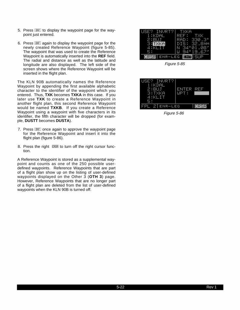
5-22 Rev 1
5. Press E to display the waypoint page for the way-point just entered.
6. Press E again to display the waypoint page for thenewly created Reference Waypoint (figure 5-85).The waypoint that was used to create the ReferenceWaypoint is automatically inserted into the REF field.The radial and distance as well as the latitude andlongitude are also displayed. The left side of thescreen shows where the Reference Waypoint will beinserted in the flight plan.
The KLN 90B automatically names the ReferenceWaypoint by appending the first available alphabeticcharacter to the identifier of the waypoint which youentered. Thus, TXK becomes TXKA in this case. If youlater use TXK to create a Reference Waypoint inanother flight plan, this second Reference Waypointwould be named TXKB. If you create a ReferenceWaypoint using a waypoint with five characters in itsidentifier, the fifth character will be dropped (for exam-ple, DUSTT becomes DUSTA).
7. Press E once again to approve the waypoint pagefor the Reference Waypoint and insert it into theflight plan (figure 5-86).
8. Press the right C to turn off the right cursor func-tion.
A Reference Waypoint is stored as a supplemental way-point and counts as one of the 250 possible user-defined waypoints. Reference Waypoints that are partof a flight plan show up on the listing of user-definedwaypoints displayed on the Other 3 (OTH 3) page.However, Reference Waypoints that are no longer partof a flight plan are deleted from the list of user-definedwaypoints when the KLN 90B is turned off.
Figure 5-86
USE? INVRT?| 1:KDAL | 2:BUJ |ENTER REF 3:TXKA |WPT: 4:KLIT | 5: | FPL 2 enr-leg CRSR
Figure 5-85
USE? INVRT?| TXKA 1:KDAL |REF: TXK 2:BUJ |RAD: 330.3^ 3:TXKA |DIS: 32.8nm 4:KLIT |N 34^01.08' 5: |W 94^19.67' CRSR enr-leg ent SUP

5-23 Rev 1
THIS PAGE INTENTIONALLY LEFT BLANK

Figure 5-87
DENVER
MIN
NE
AP
OLIS
DE
NV
ER
McCOOK
GOODLAND
DENVER
ALBUQUERQUE
KANSAS C
ITY
ALBUQ
UER
QU
E
ALBUQ
UERQUE
FT W
ORTH
AMARILLO
WICHITA
TULSA
DALLAS-FT WORTH
ABILENE
OMAHA
KANSAS CITY
LUBBOCK
MEMPHISFT WORTH
MINNEAPOLIS
KANSAS CITY
CENTER WAYPOINTS(Not For Actual Navigation)
DENVER
KANSAS CIT
Y
327°29.7nm
GCKGarden City
VOR
352°29.7nm
BGDBorgerVOR
1°28.7nm
PVWPlainview
VOR
GCK00
BGD00
PVW00
5-24

5-25 Rev 1
5.6 CENTER WAYPOINTS
Like Reference Waypoints, creating Center Waypointsis a method of adding waypoints to a flight plan. Theword “Center” refers to air route traffic control center(ARTCC) or area control center (ACC). In some parts ofthe world these are referred to as “FIRs”. CenterWaypoints are waypoints at locations where a flight planintersects the “Center” boundaries. You may findCenter waypoints useful when filing flight plans or com-plying with ATC requests to make sure that you have atleast one waypoint in each Center’s airspace. Placingwaypoints on the boundaries results in the minimumnumber of waypoints required to meet the criteria ofhaving one waypoint in each Center’s airspace. TheCenter boundaries are stored in the database.
An example will illustrate the Center Waypoint feature.You are planning a f l ight from Lubbock, TexasInternational airport (KLBB) to McCook, NebraskaMunicipal airport (KMCK) as shown in figure 5-87. Aflight plan is initially created with just these two way-points (figure 5-88). In order to give ATC more way-points for your intended direct routing, you decide to uti-lize the Center Waypoint feature.
5.6.1 Creating Center Waypoints And Inserting Themin Flight PlansTo create the Center Waypoints:
1. Select the Center Waypoint 1 (CTR 1) page on theright side. If a flight plan page is not being displayedon the left side, the CTR 1 page will be as shown infigure 5-89.
2. Select the desired flight plan page on the left side.At this point it may be the active flight plan or one ofthe other 25 numbered flight plans (figure 5-90).
3. Press E to compute the Center waypoints. ACenter Waypoint will be created at each intersectionof the flight plan with a center boundary. When com-putation is complete, the CTR 1 page will displayhow many Center waypoints have been computed(figure 5-91).
4. If you wish to view the Center Waypoints beforeinserting them into the flight plan, turn the right innerknob to view the CTR 2 page(s). If there are multipleCenter Waypoints, there will be an equal number ofCTR+2 pages.
An example of a CTR 2 page is figure 5-92. The topline contains the identifier of the Center Waypoint. TheKLN 90B automatically creates the identifier by append-ing the first available 2-digit number to the identifier ofthe nearest VOR to the waypoint. Thus, if Plainview
Figure 5-88
USE? INVRT?| DIS ETE 1:KLBB | 2:KMCK | 396 3: | | | FPL 3 enr-leg D/T 1
Figure 5-89
PRESENT POS| |DISPLAY DBQ 274^fr|DESIRED 21.3nm|FPL ON N 42^26.90'|LEFT PAGE W 91^11.12'| NAV 2 enr-leg CTR 1
Figure 5-90
6
USE? INVRT?| 1:KLBB | 2:KMCK |PRESS ENT 3: |TO COMPUTE |CTR WPTS | FPL 3 enr-leg ent CTR 1
Figure 5-92
| PVW00 new |FW -ABQ CTR |PVW 001^ | 28.7nm |N 34^33.21' |W101^40.01' CTR[2
Figure 5-91
| 3 NEW WPTS | |PRESS ENT |TO INSERT |INTO FPL | CTR 1

5-26 Rev 1
(PVW) is the nearest VOR to the first Center Waypointlocation, the 00 is appended to PVW to create PVW00.If PVW were later used in the creation of another CenterWaypoint, the second waypoint’s identifier would bePVW01.
The second line of the CTR 2 page shows the “from”Center followed by the “to” Center. In our example,PVW00 lies on the boundary between Ft. Worth (FW)and Albuquerque (ABQ) Centers. See figure 5-87. Alisting of the Center abbreviations is contained inAppendix D.
The third and fourth lines of the CTR 2 page display theCenter Waypoint location in terms of the identifier of thenearest VOR to the Center Waypoint and the distanceand radial from this VOR to the Center Waypoint. Linesfive and six display the Center Waypoint location interms of latitude and longitude.
5. Insert the Center Waypoints into the displayed flightplan by returning to the CTR 1 page on the right sideand pressing E (f igure 5-93). The CenterWaypoints are inserted into the flight plan in the cor-rect order.
In the example above, the initial flight plan had just oneleg; however, the Center Waypoint feature may be usedwith flight plans containing multiple legs as well. Ifinserting the Center Waypoints would cause the numberof waypoints to exceed 30, then no Center Waypointsare displayed and the CTR 1 page will display the state-ment “NOT ENOUGH ROOM IN FPL”.
5.6.2 Viewing the Center Waypoints After Insertion Into A Flight Plan
After the Center Waypoints have been inserted into aflight plan, you may go back and view the CTR 2 pagesat any time. As long as you keep the same flight planpage displayed on the left side of the screen, you mayview the Center Waypoints on the CTR 2 page(s) bymerely displaying the CTR 2 page(s). However, theCTR 1 and CTR 2 pages revert to the format of figure 5-90 anytime you leave the specific flight plan page on theleft side and then return to it. Under these circum-stances you must press E to view the CenterWaypoints on the CTR 2 page(s).
Center Waypoints are stored as part of the 250 user-defined waypoints and are considered supplementalwaypoints. When Center Waypoints are viewed on theSUP page or on the Active Waypoint (ACT) pages, theyappear in the normal supplemental waypoint format (fig-ure 5-94). Center Waypoints that are part of a flightplan show up on the Other 3 (OTH 3) page. CenterWaypoints that are no longer part of a flight plan aredeleted from the list of user-defined waypoints when theKLN 90B is turned off.
Figure 5-93
USE? INVRT?| 1:KLBB | 2:PVW00 |CTR WPT 3:BGD00 |INSERTION 4:GCK00 |COMPLETE 5:KMCK | FPL 3 enr-leg CTR 1
Figure 5-94
| PVW00 |REF: PVW |RAD: 001.2^ |DIS: 28.7nm |N 34^33.21' |W101^40.01' SUP

5-27 Rev 1
5.6.3 Creating Center Waypoints After Modifying A Flight Plan
Once Center Waypoints have been inserted into a flightplan, they are treated like any other waypoints in theflight plan. If a flight plan containing Center Waypointsis modified in any way, you may recompute new CenterWaypoints. The original Center Waypoints are now partof the flight plan and new Center Waypoints are com-puted by treating the original Center Waypoints thesame as any other waypoints in the flight plan.
If the interior of a f l ight plan containing CenterWaypoints is modified, it may be desirable to manuallydelete obsolete Center Waypoints from the flight planbefore computing new ones. However, if the flight planis modified by adding new waypoints to the end of theflight plan, this may not be necessary. For example,let’s say you decide to modify your existing flight planfrom Lubbock to McCook by extending your flight toOmaha (figure 5-95). When you use the CTR 1 page tocomputer Center Waypoints, the CTR 1 page will nowbe as shown in figure 5-96. The newly computedCenter Waypoint is identified as “NEW” on the CTR 2page (figure 5-97) while the existing Center Waypointsno longer contain the “NEW” label.
Figure 5-95
1:KLBB | 2:PVW00 | 3:BGD00 | 4:GCK00 | 5:KMCK | 6:KOMA | FPL 3
Figure 5-96
| 1 NEW WPT | |PRESS ENT |TO INSERT |INTO FPL | CTR 1
Figure 5-97
| EAR00 new |DEN-MIN CTR |EAR 182^ | 8.1nm |N 40^35.57' |W 99^02.54' CTR[2

5-28 Rev 1
5.7 PROGRAMMING THE TURN-ON PAGE
You may personalize your KLN 90B by programminginformation on the Turn-On page. Up to four lines, eachcontaining 23 characters, may be entered. The charac-ters A through Z, the numbers 0 through 9, and spacesmay be used. Once programmed, this information willbe displayed for a few seconds each time you applypower to your KLN 90B. The example in figure 5-98might give you some ideas, but use your imagination.How about programming the date your medical expires,or the date of your next biennial is due, or your weddinganniversary so that you’ll be reminded each time youturn-on the unit? To program data on the Turn-Onpage:
1. Turn the KLN 90B off if it is on.
2. Turn on the unit. As soon as you see the Turn Onpage (figure 5-99, press the left C). You’ll have tobe ready because the Turn-On page is onlydisplayed for a few seconds before automaticallybeing replaced by the Self Test page (or the Take-Home page if the KLN 90B is being used in the take-home mode).
3. To program the first line (third line of display), usethe left inner knob to select each desired character,and use the left outer knob to move the cursor.Spaces may be entered at the beginning of a line tocenter the text. If you make a mistake, you maymove the cursor back to the desired location and re-enter the character. When the first line is complete,press E. The cursor will move to the second line.
4. Program the second, third, and fourth lines as youdid the first line. Remember that you must pressE to approve each line, including the last one.
5. If you wish to delete the text on a line you havealready approved, use the left outer knob to positionthe cursor over the entire line. Enter a space for thefirst character in the line, and then press E.
6. When you are finished programming the Turn-Onpage, press the left C. Turn the unit off and backon - how does it look?
Figure 5-98
GPS ORS 20 c1994 ALLIEDSIGNAL INC FRANKLIN SMITH PILOT OWNER N39296 SELF TEST IN PROGRESS
Figure 5-99
GPS ORS 20 c1994 ALLIEDSIGNAL INC SELF TEST IN PROGRESS

5-29 Rev 1
5.8 THE STATUS PAGES
There are four Status pages. The Status 1 and Status 2pages display information pertaining specifically to theGPS receiver while the Status 3 and Status 4 pagesdisplay supplementary information pertaining to the KLN 90B.
5.8.1 Determining The Status Of The GPS SignalsThe Status 1 (STA 1) and Status 2 (STA 2) pages maybe viewed at any time to determine the status of theGPS receiver and the GPS satellites being received.This includes which satellites are being tracked, thesatellites’ health, the signal-to-noise ratio for each ofthese satellites, the elevation of each satellite above thehorizon, and the estimated position error.
The GPS receiver in the KLN 90B is capable of usingsignals from up to eight satellites to determine its posi-tion. A valid position may be determined using as fewas four satellites alone or three satellites with an altitudeinput. However, four satellites alone or three satelliteswith an altitude input do not necessarily ensure that nav-igation can take place. The satellites must be posi-tioned relative to your location such that sufficient“geometry” exists to determine an accurate position.The satellite constellation geometry is continuallychanging as each satellite rises, travels across the sky,and eventually sets relative to your position. The GPSsatellites are not in geosynchronous orbits positionedover the same spot on earth at all times like some televi-sion communication satellites with which you may befamiliar. Rather, the GPS satellites are in orbits thatallow them to circle the earth about two times each day.
Figures 5-100 and 5-101 show a representative exam-ple of a set of STA 1 pages. There will be two STA 1pages if more than four satellites are being received asin this example. The fact that there are two Status 1pages is indicated in the page identification segment bythe “+” in STA+1. The following information is displayedon a STA 1 page.
The GPS state is indicated on line 1:
INIT initializationACQ acquisitionTRAN transitionNAV navigationNAV A navigation with altitude aidingNAV D navigation with data collectionDEGRD navigation with position degradationFAILR receiver failure
In the initialization state the GPS receiver is in theprocess of initializing itself, collecting information suchas the date, time, and last present position. Next, thereceiver collects data from its own memory to determinewhich satellites should be visible. After completing the
Figure 5-100
STATE NAV| SV SNR ELE| 02 40 11^| 11 42 47^| 16 36 06^| *18B 33 65^| STA[1
Figure 5-101
19 46 59^| 28 45 43^| | | | | STA[1

5-30 Rev 1
initialization process the receiver begins the acquisitionprocess. During this time, the visible satellites are beingacquired and data from them is obtained.
The transition state indicates an adequate number ofsatellites for navigation has been acquired and is beingtracked but no position data can yet be produced.
Normal navigation is indicated by a NAV, NAV A, orNAV D GPS state. NAV A indicates that the altitudeinput is being used in the position solution. NAV D indi-cates that besides calculating position, the receiver iscollecting and storing in its memory additional data infor-mation from the satellites (called ephemeris andalmanac data).
• The specific GPS satellites or “space vehicles” (SV)being received are displayed in the left column.Each satellite has its own identification number. A *symbol to the left of the satellite number indicatesthis particular satellite is not presently being used inthe navigation position solution.
• The satellite’s “health” is indicated to the right of thesatellite number. This health information is transmit-ted by the satellites:
B badW weak- unknownblank good
• The signal-to-noise ratio (SNR) for each satellitebeing received is displayed in the middle column andindicates the signal strength for each satellite. Thehigher the SNR value the stronger the signal.Values usable for navigation will be in the mid 30s tomid 50s; however, typical values are in the middle ofthis range.
• The elevation (ELE) above the horizon for eachsatellite is provided in the right column and will rangefrom 5° to 90°.
A representative Status 2 page is shown in figure 5-102.The STA 2 page displays the system’s estimate of theposition error expressed in nautical miles. The KLN90B’s position error depends upon such factors as thenumber of satellites being received, the strength of theGPS signals, and the geometry of the satell i tespresently being used for navigation.
Figure 5-102
ESTIMATED | POSN ERROR | .07nm| | | | STA 2

5-31
5.8.2 Determining KLN 90B Software Status And Operational Time
The Status 3 page (figure 5-103) displays the softwarerevision status of the KLN 90B host computer and of theGPS receiver. A field called OBS CAL is also includedon this page. This value indicates the calibration of theinternal resolver circuitry of the KLN 90B. If for somereason your KLN 90B requires service, the informationon this page may be useful.
The Status 4 page displays the KLN 90B’s total opera-tional time and also the number of times the unit hasbeen turned on (figure 5-104). Kind of like having a builtin Hobbs meter, isn’t it! These values are set to zero ifthe KLN 90B’s nonvolatile memory is cleared.
Rev 1
Figure 5-103
HOST SW 20|RCVR SW 20|OBS CAL 96| | | |STA 3
Figure 5-104
TOTAL TIME | 1364 HR| PWR CYCLES | 581 | | | STA 4

5-32 Rev 1
5.9 MODES OF OPERATION
The KLN 90B allows you to choose how the course tothe active waypoint is defined. This is done by selectingbetween the two course modes, LEG and OBS. TheLEG mode means that the course to the active waypointis selected by the KLN 90B, and is the default modewhen the KLN 90B starts up. The other course mode,OBS, is the mode that allows you to define the course tothe active waypoint. This is the mode that you will usequite often if you conduct any non-precision approachesusing the KLN 90B.
The KLN 90B also has three modes that are associatedwith approach operations. These are Enroute, ApproachArm and Approach Active. These modes wil l beexplained in chapter 6.
The status of the course modes and the approachmodes are annunciated in the lower center segment ofthe screen (figure 5-105). The exceptions to this are onthe Turn-On page where the mode is not annunciated,and on the Super NAV 5 page where the mode isannunciated on the left side of the screen (figure 5-106).The following abbreviations are used for mode annunci-ation.
Mode Annunciation
Enroute-Leg ENR-LEGEnroute-OBS ENR:274
Approach Arm-Leg ARM-LEGApproach Arm-OBS ARM:259Approach Active-Leg APR-LEG
The approach active-OBS mode is not a valid mode andcannot be selected.
For the OBS modes, the number included in the annun-ciation is the selected magnetic course. The coursemay be changed by several different methods which aredescribed below.
5.9.1 Selecting The Leg Mode Or The OBS ModeYou will use one of two methods to change betweencourse modes depending on how the KLN 90B isinstalled in your aircraft. In some installations, there willbe some type of external switch and annunciators thatwill select the mode and indicate the status of thecourse modes. In other installations these switches willnot be installed.
Use the following procedure to change to either the Legmode or the OBS mode when no external course modeswitch is installed:
1. Select the MOD type pages on the left side. TheMOD page corresponding to the active mode will bedisplayed (figure 5-107).
Figure 5-107
ACTIVE MODE| | |LEG | |CDI:±5.00NM|MOD 1 enr-leg
PRESENT POS| $=KOSH |+++++Ê+++++ LGA 045^fr|DIS 683nm 15.2nm|GS 193kt N 41^00.00'|ETE 3:34 W 73^41.60'|BRG 303^ NAV 2 enr-leg NAV 1
Figure 5-106
80.2 oqCEW |xy-«} | 180 uváà0:26|ûü085^|†ü084^|160
CEW
SJI
MAI
Figure 5-105

5-33 Rev 1
2. Rotate the left inner knob to select the MOD page forthe desired mode: MOD 1 to select Leg or MOD 2 toselect OBS (figure 5-108).
3. Press E (figure 5-109). The mode change is com-plete and you may return to any desired page.
It is not possible to change the mode by using the MODpages when an external switch is installed. If youattempt to change the mode by using the MOD pagesthey will appear as shown in figure 5-110. Use thefollowing procedure when an external LEG/OBS switchis installed in the aircraft:
1. Locate the external switch in the panel of the aircraft.An example of an external switch annunciator isshown in figure 5-111.
2. Change the position of the external switch. In the caseof the combination switch/annunciator all that youhave to do is press the unit and it will switch modes(figure 5-112).
5.9.2 The Leg ModeThe following are characteristics of the Leg Mode:
1. The default course deviation indicator (CDI) sensitivityis plus and minus five nautical miles, full scale. Thisapplies to the CDI on the NAV 1 page as well as anyexternal CDIs or HSIs interfaced to the KLN 90B. Ifthe CDI or HSI has five dots left and right of the centerposition, then each dot represents one nautical mile ofdeviation.
NOTE: In some installations where the KLN 90B isinterfaced to certain models of EFIS equipment, the scalefactor will be plus or minus 7.5 nautical miles, full scale.Refer to the Flight Manual Supplement for the aircraft orthe Pilot’s Guide for the EFIS equipment for details.
2. Navigation is provided along the great circle pathbetween two waypoints. As you probably know, greatcircle navigation is the shortest distance between twopoints located on the earth’s surface. In the case ofDirect To operation, the “from” waypoint is notdisplayed but it is the point where Direct To operationwas initiated. The course to fly while in this mode isreferred to as the desired track (DTK). The desiredtrack is displayed on the NAV 3 and D/T 3 pages. Youcan also configure the Super NAV 5 page to displaydesired track, see section 3.9.7. To fly a great circlecourse between two points, the desired track may beconstantly changing. A good way to illustrate thisconcept is with a world globe and a piece of string.You can determine the great circle path betweenDenver, Colorado and Manila, Philippines by stretch-ing the string over the globe between these twopoints. Notice that you would start the flight with aNorthwesterly desired track, which gradually becomes
Figure 5-108
PRESS ENT |TO ACTIVATE| |OBS:---^ | |CDI:±5.00NM|MOD 2 enr-leg ent
Figure 5-109
ACTIVE MODE| | |OBS:023^ | |CDI:±5.00NM|MOD 2 enr-leg
Figure 5-110
PRESS GPS |CRS FOR | |OBS:---^ | |CDI:±5.00NM|MOD 2 enr-leg
Figure 5-111
GPS CRS
LEG
GPS CRS
OBS
Figure 5-112

5-34 Rev 1
due Westerly, and finally Southwesterly by the timeyou reach Manila. Of course, your trips with the KLN90B will be substantially shorter and the desired trackwill probably change only a few degrees.
3. Automatic waypoint sequencing is provided duringflight plan operation. As you reach a waypoint in yourflight plan, the next leg of the flight plan automaticallybecomes active. There are some situations duringapproach operations in which automatic sequencing isautomatically disabled, see chapter 6.
4. Turn anticipation may be utilized in flight plan opera-tion as described in section 4.2.2.
5. The Minimum Enroute Safe Altitude (ESA) displayedon the NAV 3 page is the highest MSA sector altitudefrom the present position to the destination waypointalong the active flight plan or Direct To route(whichever is in use). See section 3.9.4.
5.9.3 The OBS ModeThe following are characteristics of the OBS mode. Item1 is the same as for the Leg mode.
1. The default course deviation indicator (CDI) sensitivityis plus and minus five nautical miles, full scale. Thisapplies to the CDI on the NAV 1 page as well as anyexternal CDIs or HSIs interfaced to the KLN 90B. Ifthe CDI or HSI has five dots left and right of the centerposition, then each dot represents one nautical mile ofdeviation.
NOTE: In some installations where the KLN 90B is inter-faced to certain models of EFIS equipment, the scale fac-tor will be plus or minus 7.5 nautical miles, full scale.Refer to the Flight Manual Supplement for the aircraft orthe Pilot’s Guide for the EFIS equipment for details.
2. The course is defined by the active waypoint and theselected magnetic course. A course “to” or “from” theactive waypoint may be selected.
3. The course selection is normally made by changingthe selected course displayed on an external indica-tor such as an HSI, CDI or EFIS. When this is done,the pilot must verify that the proper course has beenselected by confirming the digital selected coursereadout displayed on the KLN 90B. In the OBS modethe selected course is always displayed as part ofthe mode annunciation at the bottom center of thescreen on all pages but the Super NAV 5 page. Onthe Super NAV 5 page, the mode/annunciation isdisplayed on the left side of the screen. In manyinstallations, two or more navigation sources candisplayed on one indicator. In these situations thereis a switch in the panel which will determine whatnavigation source is displayed. For the KLN 90B toproperly read the external indicator the KLN 90B

5-35 Rev 1
must be the displayed navigation source on theexternal indicator.
When the KLN 90B is not the displayed navigationsource on the external indicator or if the KLN 90B isinterfaced with an EFIS system, it is possible tochange the selected course from several pages onthe KLN 90B. This can be done from the NAV 3 orMode 2 (MOD 2) pages as well as the Super NAV 5page if it is configured to display the desired track onthe left hand side. To change the selected coursefrom one of these pages:
a. Select the NAV 3, MOD 2 or Super NAV 5 page(figure 5-113).
b. Press the appropriate C to turn on the cursorfunction. If the course is being changed from theSuper NAV 5 page. use the left outer knob to rotatethe cursor over the OBS angle field.
c. Turn the appropriate inner knob to select thedesired course (figure 5-114).
d. Press the appropriate C to turn off the cursorfunction.
NOTE: It is easy to tell if it is possible to enter the OBSvalue on the KLN 90B. All that has to be done is to looknext to the letters “OBS” displayed on either the MOD 2,NAV 3 or Super NAV 5 pages. If a colon (:) follows theletters OBS, then it is possible to enter a value from theKLN 90B. If the colon is missing, then the course must bechanged from the external indicator.
NOTE: If the KLN 90B is interfaced to EFIS or if the KLN90B is interfaced to certain mechanical indicators throughan optional KA 90 adapter, the external indicator will beslewed to agree with what you entered on the KLN 90B.
4. There is no automatic leg sequencing or turn antici-pation.
5. The Minimum Enroute Safe Altitude (ESA) displayedon the NAV 3 page is the highest MSA sector alti-tude from the present position to the active waypoint.See section 3.9.4. Other waypoints in the activeflight plan do not affect the ESA.
6. When the active waypoint is a VOR or an approachwaypoint, the published magnetic variation for theVOR or approach waypoint is utilized rather than thecalculated magnetic variation.
Figure 5-113
=GGT | =GGTOBS: 234^|+++++Ê+++++TK 233^|DIS 20.0nmFLY R 0.0nm|GS 154ktMSA 4500ft|ETE :08ESA 4500ft|BRG 234^NAV 3 enr:234 NAV 1
Figure 5-114
=GGT | =GGTOBS: 227^|+++++i+·+++TK 233^|DIS 20.0nmFLY R 2.4nm|GS 154ktMSA 4500ft|ETE :08ESA 4500ft|BRG 234^ CRSR enr:227 NAV 1

5-36 Rev 1
5.9.4 Switching From The Leg Mode To The OBSMode
The following mode transition occurs if the KLN 90B isin the Leg mode and the mode is changed to the OBSmode:
1. The waypoint that was active in Leg mode prior tothe mode change remains the active waypoint inOBS mode.
2. The selected course is defined by two different meth-ods depending on the installation and the status ofthe unit.
i. If the KLN 90B is the displayed navigationsource when the change is made to OBS mode, thenthe selected course becomes whatever was set onthe external indicator prior to changing to the OBSmode. This value should normally be the desiredtrack to the active waypoint if you had the externalindicator set to the correct value prior to switching tothe OBS mode.
ii. If the KLN 90B is interfaced with compatibleEFIS systems, a compatible mechanical HSIinterfaced through a KA 90 adapter, or if the KLN90B is not displayed on the external indicator, thenthe selected course is chosen such that the deviationfrom the selected course remains the same.
3. If the OBS value chosen by default from rule 2 aboveis unacceptable, you can always define the desiredcourse by the methods described in section 5.9.3.
5.9.5 Switching From The OBS Mode To The Leg Mode
The following mode transition occurs if the KLN 90B isin the OBS mode and the mode is switched to the Legmode:
1. The waypoint that was active while in the OBS moderemains the active waypoint when the Leg mode isactivated. The system does not attempt to orientitself on a leg of the active flight plan unless theTO/FROM indicator is indicating FROM. In this casethe KLN 90B will reorient on the active flight plan.
2. The selected course (OBS) that was active in theOBS mode prior to switching to a Leg modebecomes the desired track (DTK) in the Leg mode,unless the switch was made on the “from” side inwhich case the KLN 90B will calculate the correctdesired track for the new leg.
3. With the exception of #2 above, the characteristics ofnormal Direct To operation apply.

5-37 Rev 1
5.9.6 Going Direct-To A Waypoint While in the OBS Mode
The direct-to function will select the OBS value that willtake the aircraft from the present position direct to theactive waypoint when the KLN 90B is interfaced toEFIS, a compatible mechanical HSI interfaced through aKA 90, or when the KLN 90B is not the displayed navi-gation source on the external indicator.
If the KLN 90B is the displayed navigation source on anon-driven HSI or a CDI it is not possible for the KLN90B to change the OBS value. In these situations theKLN 90B will provide a scratch-pad message that willtell you what OBS value should be selected to go directto the active waypoint (figure 5-115).
5.9.7 Activating A Waypoint While In The OBS ModeWhile in the OBS mode, you may activate another way-point by using the normal Direct To method or by usinga second method. This second method activatesanother waypoint without changing the selected course(OBS). In other words, when the new waypoint is acti-vated, the D-Bar is not recentered. In figure 5-116 theKLN 90B is in the OBS mode and the selected course is90°. You have just crossed INITT intersection anddesire to activate the next waypoint in the flight plan,FINAL, without recentering the D-Bar.
1. Press D (figure 5-117). The rules described insection 3.8, “DIRECT TO OPERATION”, dictatewhich waypoint identifier will be initially displayed onthe Direct To page.
2. Press D a second time. The annunciationDIRECT TO changes to ACTIVATE (figure 5-118).The right side still displays the appropriate waypointpage. Repeated presses of D alternates betweenDIRECT TO and ACTIVATE. Make sure ACTIVATEis displayed.
3. Press E to approve the waypoint page and acti-vate the waypoint (figure 5-119). The selectedcourse does not change, therefore this method doesnot center the D-Bar like a Direct To operation.
5.9.8 Changing the CDI Scale FactorThe CDI scale factor can be changed by using either theMOD 1 or MOD 2 pages. In normal operations it ispossible to select a CDI scale factor which is plus orminus 5 NM, 1 NM or 0.3 NM full scale deflection. Thismeans that if the scale factor was ±1 NM and the needlewas deflected full scale to the right, the aircraft would be1 NM left of course. The default CDI scale factor is ±5NM.
Figure 5-118
ACTIVATE: | FINAL |REF: BTV FINAL |RAD: 292.8^ |DIS: 11.7nm |N 44^25.40' |W 73^27.20' CRSR enr:090 ent INT
Figure 5-119
3:GGT | =FINAL 4:BEGIN |+++·+i+++++ 5:INITT |DIS 4.8nm = 6:FINAL |GS 122kt 7:MMAPP |ETE :02 8:KHOM |BRG 088^ FPL 0 enr:090 NAV 1
Figure 5-116
3:GGT | =INITT 4:BEGIN |+++·+j+++++ = 5:INITT |DIS 0.4nm 6:FINAL |GS 122kt 7:MMAPP |ETE :00 8:KHOM |BRG 275^ CRSR enr:090 NAV 1
Figure 5-115
| =GGT |+++++i+·+++ |DIS 20.0nm |GS 154kt |ETE :08 |BRG 234^ $= CRS 234 NAV 1
Figure 5-117
DIRECT TO: | FINAL |REF: BTV FINAL |RAD: 292.8^ |DIS: 11.7nm |N 44^25.40' |W 73^27.20' CRSR enr:090 ent INT

5-38 Rev 1
If it is desired to change the CDI scale factor to anothervalue, use the following procedure:
1. Select either the MOD 1 or MOD 2 page.
2. Press the left C. If necessary, use the left outerknob to move the cursor over the value of the CDIscale (figure 5-120).
3. Rotate the left inner knob to select the desired CDIscale factor (figure 5-121).
4. Turn the left C off. The CDI scale factor change iscomplete.
NOTE: The KLN 90B will automatically select a scalefactor while in one of the approach modes. When theKLN 90B selects a CDI scale factor it is not possible toselect a scale factor that is less sensitive than what theKLN 90B has automatically chosen. For example, asyou will see in the next chapter, the approach-armmode usually has a scale factor of ±1 NM. While in theapproach-arm mode it is not possible for you to selectthe ±5 NM scale factor. This is to ensure properoperation of the approach modes.
Figure 5-121
Figure 5-120
ACTIVE MODE| | |LEG | |CDI:±5.00NM| CRSR enr-leg
ACTIVE MODE| | |LEG | |CDI:±0.30NM| CRSR enr-leg

5-39
5.10 THE FUEL MANAGEMENT PAGES
Certain models of fuel management computers manu-factured by Shadin Company, ARNAV System, Inc, andSheltech Ltd. may be interfaced with the KLN 90B. Theprimary benefit of having the KLN 90B interfaced with a“real time” fuel management computer is that the sys-tem can continuously compute the amount of fuelrequired to reach the destination and the amount of fuelthat will be on board upon reaching the destination. Theconcept is the following. The fuel management com-puter continuously sends the rate of fuel flow and theamount of fuel remaining to the KLN 90B. The KLN 90Bcontinuously calculates the aircraft’s distance, ground-speed, and estimated time enroute (ETE) to the destina-tion waypoint. The fuel required to reach the destinationwaypoint is the ETE multiplied by the current rate of fuelflow. The amount of fuel that will be remaining at thedestination is the amount of fuel presently remainingminus the fuel required to reach the destination.
CAUTION: The KLN 90B fuel calculations are basedon the present rate of fuel flow, the present ground-speed, the present distance to destination along theprogrammed route, and the amount of fuel presentlyremaining. Before take-off, the fuel flow computermust be properly initialized with the amount of fuelon board the aircraft. Since many factors influencethe required amount of fuel to reach the destination,it is the pilot’s responsibility to view the fuel man-agement pages often to check for any significantchanges. Some factors affecting the amount of fuelrequired are power changes, altitude changes,headwind/tailwind component changes, fuel/air mix-ture adjustments, and routing changes.
The OTH 5, OTH 6, OTH 7, AND OTH 8 pages areused to display fuel management information forKLN 90B’s interfaced with compatible fuel managementcomputers. If there is no fuel management computerinterface, these fuel management pages are not dis-played.
5.10.1 The Other 5 Page (OTH 5)The OTH 5 page displays the following information(figure 5-122):
• The destination waypoint. An arrow is displayed tothe left of the identifier if the waypoint is the activewaypoint.
• The fuel units as received from the fuel managementcomputer.
GAL gallonsIMP imperial gallonsL litersKG KilogramsLB pounds
Figure 5-122
KLFT GAL|FOB 126|REQD 90|L FOB 36|RES: 00030|EXTRA 6|OTH 5

5-40 Rev 1
• The fuel presently on board (FOB). In most installa-tions this is defined by using the fuel flow computer’scontrol unit. However, if the KLN 90B is interfacedwith a compatible Shadin fuel flow computer, it ispossible to define the fuel on board by using the KLN90B. In these installations it is not required to havethe fuel flow computer’s control head installed in theaircraft. To change the present fuel on board (FOB)use the following procedure:
1. Turn to the OTH 5 page.
2. If it is possible to enter the present fuel on boardby using the KLN 90B there will be a colon (:) follow-ing FOB on the display. If the colon exists press theleft C (figure 5-123), if the colon does not exist it isnot possible to change the fuel on board through theKLN 90B (figure 5-122).
3. Enter the current fuel on board (FOB) using theleft inner knob (figure 5-124). Make sure the amountentered is consistent with the units used by the fuelflow computer.
4. Turn the left C off.
• The fuel required to reach the destination waypointat the current rate of fuel flow and the presentgroundspeed (REQD).
• The landing fuel on board (L FOB) is the fuelpresently on board minus the fuel required to reachthe destination.
• The desired fuel reserve (RES). You may enter herethe amount of reserve fuel you wish to have uponlanding. The fuel must be entered in the same unitsas displayed on the first line. To enter the reserve,press the left C, rotate the left outer knob to movethe cursor over each of the desired reserve digits,and use the left inner knob to select each digit.Press the left C when finished to turn off the leftcursor function.
• The calculated extra fuel (EXTRA). This is the land-ing fuel on board (L FOB) minus the fuel reserve(RES) you entered.
Figure 5-124
Figure 5-123
KLFT GAL|FOB: 126|REQD 90|L FOB 36|RES: 00030|EXTRA 6|OTH 5
KLFT GAL|FOB: 97|REQD 90|L FOB 46|RES: 00030|EXTRA 6|OTH 5

5.10.2 The Other 6 Page (OTH 6)The OTH 6 page displays the following information(figure 5-125):
• The endurance (ENDUR) in hours and minutes. Theendurance is calculated based on the amount of fuelremaining after subtracting out the reserve (RES)you entered on the OTH 5 or the OTH 6 page fromthe present fuel on board.
• The range (RANGE), which is the distance (nauticalmiles) that could be flown based on the endurancecalculated above and the present groundspeed.
• The fuel efficiency, which is the groundspeed dividedby the present fuel flow.
• The desired fuel reserve (RES). Same as displayedon the OTH 5 page. Changing the reserve on one ofthe two pages also changes it on the other page.
5.10.3 The Other 7 Page (OTH 7)The OTH 7 page displays rate of fuel flow. It has twoformats depending on whether the aircraft is a twinengine (figure 5-126) or a single engine (figure 5-127).
5.10.4 The Other 8 Page (OTH 8)The OTH 8 page displays the amount of fuel used. Ifinterfaced with the ARNAV fuel management computer,this page displays dashes since the ARNAV systemdoes not output fuel used. There are two formats for thepage, depending on whether the aircraft is a twin engine(figure 5-128) or single engine (figure 5-129).
5-41
Figure 5-127
FUEL FLOW | | GAL/HR| | | 10 | OTH 7
Figure 5-128
Figure 5-129
FUEL USED | | GAL| | | 12| OTH 8
Figure 5-125
FUEL DATA | | ENDUR 3:19| RANGE 597| NM/GAL 6.2| RES: 00030| OTH 6
Figure 5-126
FUEL FLOW | | GAL/HR| ENG 1 15 | ENG 2 14 | TOTAL 29 | OTH 7
FUEL USED | | GAL| ENG 1 17| ENG 2 16| TOTAL 33| OTH 8

5-42
5.11 THE AIR DATA PAGES
The Bendix/King KAD 280 and KAD 480 air data systemsas well as specific models of Shadin Company air datasystems may be interfaced to the KLN 90B. When inter-faced with one of these systems, the KLN 90B will displayreal time air data parameters such as true airspeed (TAS),static air temperature (SAT), total air temperature (TAT),Mach number, density altitude, and pressure altitude.With a TAS input from an air data computer and a compat-ible heading input, the KLN 90B will calculate and displayreal time wind data (magnitude and direction).
NOTE: Heading information inputs to the KLN 90B mustbe in a format which is different than available from mostmechanical compass systems, including the Bendix/KingKCS 55A (KI 525A with bootstrap heading synchro) andKCS 305 compass systems. However, the Bendix/KingKA 90 adapter as well as the compatible Shadin air datasystem will convert three wire analog heading informationfrom these mechanical systems into the proper format.Bendix/King electronic HSIs such as the EHI 40 and EHI50 directly provide heading information to the KLN 90B.
The Other 9 and Other 10 (OTH 9 and OTH 10) pages areused to display air data information if both a fuel manage-ment system and an air data system are interfaced to theKLN 90B. If there is no fuel management system, air datainformation is displayed on the Other 5 and Other 6pages. If there is no air data system interface, thesepages are not displayed.
NOTE: These air data pages receive inputs from air datasensors and display real time air data information. Theyare independent of the CAL 1, CAL 2, and CAL 3 pageswhich rely on manual pilot inputs to calculate air data infor-mation.
Rev 1

5-43
5.11.1 The Other 9 Page (OTH 9)Without a fuel management system this becomes theOTH 5 page. The following information is displayed(figure 5-130):
TAS True airspeed (the true speed of an aircraftthrough the surrounding air mass)
MACH Mach number (the ratio of the true airspeed tothe speed of sound at a particular flightcondition).
If a compatible source of heading information is providedto the KLN 90B, the following wind data is also displayed(figure 5-131):
TLWND Tailwind component of the wind HDWND Headwind component of the windWIND The wind direction relative to true North and
the wind speed5.11.2 The Other 10 Page (OTH 10)Without a fuel management system this become theOTH 6 page. The following information is displayed(figure 5-132):
SAT Static air temperature (the actual tempera-ture of the surrounding air mass)
TAT Total air temperature(the air temperatureincluding heat rise due to compressibility.This is the temperature measured directly bythe OAT probe.
PRS Pressure altitude (to nearest 100 feet)
DEN Density altitude (to nearest 100 feet).
Rev 1
Figure 5-130
Figure 5-131
AIR DATA | TAS 229kt| MACH .34| | | | OTH 9
AIR DATA | TAS 229kt| MACH .34| HDWND 30kt| WIND 078^%| 32kt| OTH 9
Figure 5-132
AIR DATA | | SAT 20^C| TAT 26^C| PRS 6500ft| DEN 9100ft| OTH10

5-44
5.12 OPERATION OUTSIDE THE PRIMARY COVERAGE AREA
The KLN 90B’s primary coverage area is from N 74° toS 60° latitude as was shown in figure 3-1. All navigationdata presented outside this area is automatically refer-enced to true North unless a manual input of magneticvariation is made on the SET 2 page. The same is trueanytime the KLN 90B is in the OBS mode and the activewaypoint is outside the primary coverage area. Underboth of these conditions, the following message will bedisplayed on the Message page:
MAGNETIC VAR INVALIDALL DATA REFERENCEDTO TRUE NORTH
When navigation is within the primary coverage area,the SET 2 page does not display magnetic variation (fig-ure 5-133). However, under the conditions statedabove, a user entered magnetic variation may be madeon line 6 of the SET 2 page using the left C and leftset of knobs (figure 5-134).
5.13 OPERATION WITHOUT A DATABASE CARTRIDGE
The KLN 90B is designed so that a database cartridgeis required for normal operation. However, in the eventthat the cartridge is inadvertently not inserted or that thecartridge fails, there is a reversionary mode providingpartial operation that may be used.
NOTE: Reversionary operation without a databasecartridge should only be used for VFR flight, not for IFR.
Without a database cartridge inserted, the Databasepage appears as in f igure 5-135. All publishedwaypoints (those that originated from the databasecartridge) have been deleted from the active flight plan,FPL 0. Therefore, the only waypoints remaining in FPL0 are any user-defined waypoints that were originallyincluded in the flight plan.
The KLN 90B is unable to calculate magnetic variationwithout the database cartridge. Therefore, a magneticvariation must be manually inserted on the Databasepage when there is no cartridge. Use the right inner andouter knobs to enter the desired magnetic variation andpress E to enter (figure 5-136). With the cursor posi-tioned over ACKNOWLEDGE?, press E to approvethe Database page. The magnetic variation can beentered on the Database page and on line 6 of the SET2 page (figure 5-134).
Rev 1
Figure 5-133 Figure 5-134
DATE/TIME | | 30 MAY 92| 14:59:28UTC| CORD UNIV/Z| | SET 2
DATE/TIME | | 30 MAY 92| 14:59:28UTC| CORD UNIV/Z| MAG V 10^W| SET 2
Figure 5-135
NO DATA BASE CARTRIDGE PRESENT PUBLISHED WPTS HAVE BEEN DELETED FROM FPL 0 MAGNETIC VARIATION:!!^! ACKNOWLEDGE? enr-leg CRSR
NO DATA BASE CARTRIDGE PRESENT PUBLISHED WPTS HAVE BEEN DELETED FROM FPL 0 MAGNETIC VARIATION:06^E ACKNOWLEDGE? enr-leg CRSR
Figure 5-136

5-45
The active flight plan is the only flight plan availablewhen there is no database cartridge. There is no way togain access to flight plans one through 25. Functionsnot requiring the published database are operative.Some functions, such as nearest airport, nearest VOR,nearest NDB, Reference Waypoint, and trip planning,are operational but only to the extent that user-definedwaypoints are utilized. Functions that depend on thedatabase cartridge are not operative. Some of theseinclude Special Use Airspace, Minimum Safe Altitudes,ARTCC waypoints, FSS frequencies on the OTH 1page, and ARTCC frequencies on the OTH 2 page.Non-precision approaches, SIDs and STARs are alsodisabled.
Rev 1

5-46
5.14 USING THE TAKE-HOME MODE
It is very likely that the KLN 90B will become your “bestfriend” in the cockpit. As with any good friend, you mayneed some time to get well-acquainted. This will allowyou to utilize it to the maximum extent. A great way to getto know the KLN 90B is to use it outside the airplane,using what we call the “take-home mode”.
There are products available which allow you to use theKLN 90B at your home, office, or hotel to have get-acquainted time in the take-home mode, for instance theCommander 2000 from Lone Star Aviation. It is alsohelpful to do flight planning and perform databaseupdates outside the airplane, perhaps with a homepersonal computer.
When the KLN 90B is in the take-home mode, it performsas if it is receiving adequate satellite signals to determineits position. It displays the latitude and longitude of its lastknown position or of whatever position it is initialized to onthe Setup (SET 1) page (see section 3.6, “Initializationand Time to First Fix”). In addition, a ground speed andheading may be entered on the SET 1 page and the KLN 90B will track a flight plan or a direct to waypoint justas if it was actually functioning in an aircraft. Distancescount down, waypoints sequence, and the deviation barfollows the progress of the simulated flight. Using thetake-home mode is an excellent way to learn theoperation of the KLN 90B without worrying about theengine running, other traffic, or even terrain (fortunately,these phenomena are not simulated in the take-homemode!)
Rev 1

6-1
This is the last chapter on the operation of the KLN 90B.In this chapter you will learn how to use the KLN 90B fornon-precision approaches as well as SID/STAR proce-dures. All of these procedures require that you are com-
fortable with the operation of the unit as presented up tothis point. In particular, you need to be comfortable withflight plan operation (chapter 4) and the OBS mode(section 5.9).
Rev 1
CHAPTER 6 - LEVEL 4 OPERATION
6.1 NON-PRECISION APPROACH OPERATIONS
Flying non-precision approaches using the KLN 90B arenot in themselves very difficult. However, it is differentthan using traditional equipment such as VORs andNDBs. With this in mind, make sure that you practicewith the KLN 90B in VFR weather with a check pilotbefore attempting to use the KLN 90B in actual IFR condi-tions.
CAUTION: The KLN 90B obtains approach informa-tion from the database. Therefore, it is extremelyimportant that the database is current. The KLN 90Bis approved for IFR non-precision approaches onlywhen the database is current. If you attempt to selectan approach when the database is out of date, youwill be given the status-line message: “OUTDATEDDB” in the bottom center portion of the screen as areminder.
The following sections assume that your KLN 90B isproperly installed in the aircraft with all of the necessaryaccessories to fly non-precision approaches. In mostcases this will mean that the aircraft has externalswitch/annunciators to arm the approach mode and toselect the LEG or OBS modes. An external annunciatorto indicate when a message is active and when waypointsequencing is about to occur will also be installed. Insome installations the aircraft will have a NAV/GPSswitch to select which navigation source is displayed onthe primary HSI or CDI.
The Super NAV 5 page has been specifically designed toprovide most of the functions needed for non-precisionapproaches. This page provides an interface that pre-sents pertinent navigation information, a way to accessthe flight plan, and a graphic presentation of the presentposition relative to the flight plan waypoints. You will findthis page to be a good friend while performing GPSbased non-precision approaches.
NOTE: There are some approach procedures in theworld that are not suited for the operational characteris-tics of the KLN 90B. These procedures are not includedin the database. Therefore it is not possible to use theKLN 90B for these approaches. It is good preflight prac-tice ensure that the KLN 90B contains anticipated proce-dures for the flight.
In addition to the two course modes (Leg and OBS)described in section 5.9, there are also two approachmodes. These are approach arm and approach active.The status of the approach mode is indicated both on anexternal switch/annunciator and on the status line of theKLN 90B. In most installations the external annunciatorwill indicate ARM for the approach arm mode andapproach active will be annunciated by ACTV. The maindifference of these modes from the normal enroute modeis that the integrity monitoring is set to a tighter level.Another difference between these modes and the enroutemode is that the CDI scale factor will usually change to±1.0 NM for ARM and will always change to ±0.3 NMwhen in the APR ACTV mode.
The ARM mode can be selected in two ways. The nor-mal way is that this mode will be selected automaticallyby the KLN 90B when the aircraft is within 30 NM of anairport and an approach is loaded in the flight plan for thatairport. It is possible to arm the approach mode at a dis-tance greater than 30 NM from the airport by pressing theexternal GPS approach switch, but the KLN 90B will notchange the CDI scale factor until the aircraft reaches the30 NM point. If the GPS APR external switch is pressedwhile the approach mode is armed, then the KLN 90B willdisarm the approach and change back to enroute mode.The CDI scale factor will also change back to ±5.0 NM.The approach can be re-armed by simply pressing theGPS APR switch again.
The APR ACTV mode can only be engaged automaticallyby the KLN 90B. To cancel the APR ACTV mode pressthe external GPS APR switch. This will change the modeto APR ARM. Once past the FAF, it is not possible toreturn to the approach active mode without conducting amissed approach and flying back to the FAF.

6-2 Rev 1
17
35
1432
MAPFAF
IAF
ARP
Approach ArmCDI Scale Factor
±1.0 nm
CDI Scale Factor ±5.0 nm
CDI Scale Factorconstant at ±0.3 nm
CDI Scale Factorchanging from
±1.0 nm to ±0.3 nm
70°
30 n
m
2 nm
Transition to approachACTV if:
- LEG mode is selected- Integrity checks OK- Aircraft heading
towards the FAF- FAF or co-located
IAF/FAF is active waypoint
Load approachinto flight plan
Approach automaticallyarms when within 30 nmof the airport and anapproach is loaded intothe active flight plan
FAF - Final Approach FixMAP - Missed Approach PointARP - Airport Reference PointIAF - Initial Approach FixMAHP - Missed Approach Holding
Point
NOT TO SCALE NOT FOR NAVIGATION
(A)
(B)
(C) (D)
(E)
MAHP(F)
Automatic Waypointsequencing stops
Figure 6-1 KLN 90B Approach Diagram

6-3
General Procedure for Non-Precision Approaches
Non-precision approaches will all have the general flow ofevents as follows. Refer to figure 6-1.
1. Select and load the approach into the flight plan.This can be done at almost any time but must be com-pleted before reaching the Final Approach Fix and shouldbe done as soon as possible. This corresponds to pointA in figure 6-1. If the aircraft is greater than 30 NM fromthe airport, then the CDI scale factor will remain at thedefault ±5 NM full scale deflection.
2. Transition to the approach arm mode. This willoccur automatically when the aircraft is within 30 NM ofthe airport and there is an approach loaded into the flightplan (position B in figure 6-1). The CDI scale factor willchange to ±1.0 NM over the next 30 seconds and theexternal annunciator will indicate ARM.
3. Get established on the final approach course.• NoPT arrival route• Radar vectors (requires OBS mode)• Procedure turn or holding pattern (requires
OBS mode)• DME arc
4. Transition to the approach active mode. Thismode change is automatic and occurs at position C infigure 6-1 when:
• the aircraft is 2 NM from the FAF and the approach mode is armed
• the LEG mode is selected• the aircraft is heading towards the FAF• the FAF or a co-located IAF/FAF is the active
waypoint• the KLN 90B confirms that adequate integrity
monitoring is available to complete the approach.• RAIM is available at FAF & MAP
Rev 1
If any of these conditions are not met, the KLN 90B willnot transition to the approach active mode and a missedapproach will be required if the conditions do not changebefore reaching the FAF. If all of these conditions aremet then the CDI scale factor will start to change to ±0.3NM and the external annunciator will indicate ACTV.
5. At the FAF (position D in figure 6-1) the CDI scalefactor will be at ±0.3 NM and will remain at this scale fac-tor until you manually cancel the approach mode by eitherpressing the external GPS APR button to change to theARM mode, by initiating a direct to operation or bychanging to OBS mode.
WARNING: It is not approved to conduct the finalportion of the approach unless the KLN 90B is in theapproach active mode (ACTV on externalannunciator).
6. Fly to the Missed Approach Point. (position E infigure 6-1). The KLN 90B will not automatically sequenceto the next waypoint. You must manually change to theappropriate waypoint according to the situation. Bydefault, the KLN 90B will nominate the first waypoint ofthe published missed approach procedure when D ispressed and the active waypoint is the MAP (rule number4 in section 3.8).
7. If necessary conduct the missed approachprocedure. Remember to always refer to the paper chartwhen conducting a missed approach. The OBS mode isusually needed at some point during a missed approachand is always required to fly the holding pattern (positionF in figure 6-1).
The details of the above operations as well as severalexamples of how to conduct non-precision approachesusing the KLN 90B are given in the following sections.

6-4
6.1.1 Selecting An ApproachThe first item in the list from the previous section is toselect and load the approach into the active flight plan.Approaches are selected from the APT 8 (or ACT 8) pageof the airport for which you desire to shoot the approach.If you are operating from a flight plan, the easiest way toget to the approach information is by turning to the ACTpage for your destination as described in section 4.2.3.
The following example will use the VOR or GPS RWY25R approach to Los Angles International airport (KLAX).
1. Turn to one of the APT pages and select KLAX byusing the right cursor, inner, and outer knobs (figure 6-2)
2. Use the right inner knob to turn to the APT 8 page. Ifyou selected KLAX from the APT 1 page turn the innerknob one click counter-clockwise to reach the APT 8page.
3. Turn the right cursor on by pressing the right C.The cursor comes up on the first approach in the list ofapproaches. Use the right outer knob to move the cursorto different approaches (figure 6-3). If there are morethan 5 approaches to an airport you can move the cursordown to “scroll” the other procedures into view by rotatingthe right outer knob.
4. With the flashing cursor over “VOR 25R” press E.
5. The KLN 90B will present a list of Initial ApproachFixes (IAFs) corresponding to this approach. In thisexample we want the ELMOO IAF. Select this by press-ing E when the cursor is over ELMOO (figure 6-4).Note: If there is only one IAF for a procedure, then theKLN 90B will skip this step and go on to the next step.
In many cases ATC will not tell you explicitly which IAF touse. In these cases you need to select an IAF which isclosest to the route of flight that you expect. If you expectradar vectors, then the selection of the correct IAF is lessimportant because you will be given vectors to the FAFand will not need to use the IAF.
6. The KLN 90B next presents a list of waypoints thatmake up the approach. Review these waypoints to makesure that you have selected the correct IAF. If there aremore than four waypoints in the approach you can movethe cursor up to “scroll” the other waypoints into view byrotating the right outer knob (figure 6-5).
7. If the cursor is over LOAD IN FPL (figure 6-6) andyou press E, then KLN 90B checks to see if this airportis in the active flight plan. If it is not, the KLN 90B will askif you want to add the approach and the airport referencepoint to the active flight plan (FPL 0). In most cases thisis desirable, so press E (figure 6-7).
Rev 1
| 9 KLAX A|LOS ANGELES| INTL|CL B|N 33^56.55'|W118^24.48' APT 1
| KLAX IAP| 1 NDB 24R| 2 VOR 07L| 3 VOR 07R| 4 VOR 25L| 5 VOR 25R ent CRSR
|V25R-KLAX|IAF 1 ELMOO| 2 LAHAB| 3 SLI| 4 SMO| ent CRSR
|V25R-KLAX| 4 FREBYî| 5 MA25Bñ| 6 LAX| 7 INISH|LOAD IN FPL CRSR
|V25R-KLAX| 1 ELMOOì| 2 LAX18| 3 FITON| 7 INISH|LOAD IN FPL ent CRSR
|V25R-KLAX|PRESS ENT|TO ADD KLAX|AND APPR TO|FPL 0| APPROVE? ent CRSR
Figure 6-2 Figure 6-3
Figure 6-4 Figure 6-5
Figure 6-6 Figure 6-7

6-5
8. The KLN 90B will then bring up the FPL 0 page andput the sequence of approach waypoints in front of theairport reference point (figure 6-8).
NOTE: At any time during the process of selecting anapproach you can easily return to the previous step bypressing the @ button.
The waypoints that make up the approach procedure areloaded into the flight plan. At the top of the list ofapproach waypoints is a “header” that describes theapproach that follows. The form of this header is ABBBB-CCCC. A is the first letter of the type of approach beingflown (e.g. V for a VOR approach). BBBB will be filled inwith the runway that the approach is to. Finally CCCCcorresponds to the identifier of the airport which theapproach is to. An example of this is shown in figure 6-8where V25R-KLAX means the VOR 25R approach toKLAX.
After the approach has been entered into the flight planthe KLN 90B checks to make sure that the resulting flightplan “makes sense”. If the KLN 90B detects any way-points that are in both the enroute portion of the flight planand the portion that makes up the approach, then the fol-lowing message will be given:
REDUNDANT WPTS IN FPL EDIT ENROUTE WPTS AS NECESSARY
Examine the flight plan and delete those enroutewaypoints that are not necessary.
NOTE: Approaches can only be entered into FPL 0, theactive flight plan. If the KLN 90B is turned off for morethan 5 minutes, then the approach is deleted when poweris turned back on.
6.1.2 Interpreting What You SeeIn the example above, you may have noticed a couple ofwaypoints with somewhat strange names. The secondwaypoint of the approach procedure, LAX18, has a namethat is not normal for a waypoint. This is an example ofwhat are called “terminal” waypoints. These are way-points that are associated with a specific airport. Theyare used to define a spot on the ground that does nothave a normal waypoint name. In the case of “LAX18”this point is 18 NM from the LAX VOR on the 68° radial.The fifth waypoint in the approach procedure, MA25B, isanother type of terminal waypoint. In this case this pointis the missed approach point for runway 25. Thisapproach applies to both the left and right runways so theletter B is used to mean “both”.
There are few other types of terminal waypoints that youwill need to be familiar with to fully understand GPS non-precision approaches. The naming convention for thesewaypoints are as follows:
Rev 1
V25R-KLAX | KLAX IAP10 ELMOOì | 1 NDB 24R11 LAX18 | 2 VOR 07L12 FITON | 3 VOR 07R13 FREBYî | 4 VOR 25L17:KLAX | 5 VOR 25RFPL 0 enr-leg APT 8
Figure 6-8

6-6
Fxyyy • F stands for Final Approach FixIxyyy • I stands for Intermediate FixCxyyy • C stands for Course FixMxyyy • M stands for Missed Approach PointRWzzz • RW stands for Runway Fix. This is
usually the MAP for the approach• zzz will be a runway number possibly including L for Left, R for Right, C for Center, or B for Both.
Daaab • D stands for DME arc waypoint• aaa is the radial that the fix is on from the reference VOR• b will be a letter corresponding to the distance from the reference VOR. For example, G is the seventh letter of the alphabet so D234G would be a point on the 234° radial 7 NM from the reference VOR. DME arcs greater than 26 NM will have waypoints where the first two characters are the first two letters of the DME identifier. The next three characterswill be the radial that the arc waypoint is on.
In the rules above x and yyy are defined as follows. Forrunways with only one approach, x will be replaced withan “A” or a “F”. For runways that have multipleapproaches, x will be replaced with “V” for VOR, “N” forNDB, or “R” for RNAV. The letters yyy will be replacedwith either the runway identifier (e.g., FF25L) or, forcircling approaches, the inbound course to the missedapproach point (e.g., MA259).
Waypoints along a given radial will be named such thatthe first three letters are the reference VOR/DME and thenext two are the DME distance. If the distance is greaterthan 100 NM the order is reversed. For example, LAX18is 18 NM from LAX while 26FLW is 126 NM from FLW.
If the aircraft is not too far from the destination airport, theSuper NAV 5 page can be used to determine wheresome of these waypoints are relative to others in theapproach. At the time of this writing, all of the NOScharts and some Jeppesen charts do not show the spe-cial terminal waypoints that are required for GPSapproaches. For this reason it is a good idea to under-stand what the special waypoints are used for and whatthey mean.
You may have also noticed that some waypoints have adash and a small letter at the end of the waypoint name.The small letter is an aid that we have added to the nameof some waypoints to help you recognize important pointsin the approach. These suffixes are displayed on the FPL0 page, the Super NAV 5 page, and the Super NAV 1page. The definitions of these suffixes are:
i - The Initial Approach Fix (IAF) of the approach.f - This is the Final Approach Fix (FAF) of the approach
Rev 1

6-7
m - The Missed Approach Point (MAP) of the approachh - The missed approach holding point for the approach
Every approach will have a FAF and a MAP. Almost allwill have an IAF and missed approach holding point.
Another item that you should notice in the flight plan is theline that has *NO WPT SEQ on it (figure 6-9). This iswhat is referred to as a fence and the purpose of this lineis to tell you that the KLN 90B will not automaticallysequence past the waypoint that precedes the fence.The waypoint before the fence is always the missedapproach point. The reason that waypoint sequencing isnot allowed is that many missed approach proceduresrequire specific actions before going to the missedapproach holding point (e.g., climbing on a fixed headinguntil reaching an altitude).
6.1.3 Changing Or Deleting An Approach OnceLoaded Into The Flight PlanThe sequence of waypoints that are retrieved from thedatabase of the KLN 90B define the approach proceduresas they are charted. To ensure that the proper path overthe ground is followed, it is not possible to either delete oradd waypoints to the approach section of the flight plan.To help you see which waypoints are enroute waypointsand which are approach waypoints, the KLN 90B doesnot display a colon next to the waypoint number on theFPL 0 page if the waypoint is an approach waypoint.
It is only possible to replace the existing approach withanother one, or delete the entire approach from the flightplan. To replace an existing approach, or delete anapproach, follow these steps.
1. With the left page displaying the active flight plan(FPL 0) turn the left cursor on by pressing the left C (fig-ure 6-10).
2. Move the cursor so that it covers the approachheader at the top of the approach procedure. Once thecursor comes over the approach header, it will automati-cally change to read CHANGE APR? (figure 6-11). If youpress E in this condition the KLN 90B will bring up theAPT 8 page that corresponds to the current approach. Atthis point it is possible to select different approach proce-dures, different IAFs, or both.
3. If you press the @ button while the cursor is overthe approach header it will change to read DELETEAPR? (figure 6-12). If you press E now, the KLN 90Bwill remove the entire approach procedure from the activeflight plan. If the KLN 90B was in the approach arm orthe approach active modes, then deleting the approachwill cause the KLN 90B to change back to enroute mode.This means that the CDI scale factor will change back tothe default ±5.0 NM scale.
Rev 1
8:LAS | 9:DAG |CHANGE APR?| 10 ELMOOì | 11 LAX18 | 17:KLAX | CRSR enr-leg
8:LAS | 9:DAG | V25L-KLAX | 10 ELMOOì | 11 LAX18 | 17:KLAX |FPL 0 enr-leg
8:LAS | 9:DAG |DELETE APR?| 10 ELMOOì | 11 LAX18 | 17:KLAX | CRSR enr-leg
Figure 6-11
Figure 6-12
Figure 6-10
Figure 6-9
13 FREBYî | 14 MA25Bñ |*NO WPT SEQ| 15 LAX | 16 INISH | 17:KLAX |FPL 0 enr-leg

6-8
6.1.4 Example Approach: No Procedure TurnNow that you know the basics of inserting an approachinto the flight plan, we can now show the approach opera-tion of the unit by several examples. This first examplewill use the approach that was loaded into the flight planin section 6.1.1. This example will show how the KLN90B sequences through an approach and what type ofannunciations and scale factor changes can be expected.The KLN 90B will remain in the familiar Leg mode sothere will be no need to change between Leg and OBSmode in this example. Refer to the approach plate forthis approach (figure 6-13) to see what the procedurelooks like.
For this example it is assumed that you are on an activeflight plan with the final destination being the Los AngelesInternational airport, KLAX. It is also assumed that ATCwill not give you radar vectors during this approach.
1. Load the VOR 25R approach to KLAX asdemonstrated in section 6.1.1.
2. When you are within 30 NM of the airport, the KLN 90B will automatically arm the approach mode andprovide the following message.
PRESS ALT TO SET BARO
The message acts as a reminder to make sure the KLN 90B is using the correct barometric pressure. If thebarometric information is not correct, then the integritymonitoring provided by the KLN 90B will not be as goodas it could be. Press A to bring up the ALT page andverify that the barometric pressure is correct.
NOTE: If the KLN 90B is interfaced with a compatible airdata computer that provides the correct barometric pres-sure to the KLN 90B, then the previous message is notdisplayed and it is not necessary to update the barometricpressure.
At this time the KLN 90B will smoothly change the CDIscale factor to ±1.0 NM. The external approach annunci-ator installed in the aircraft will indicate that the approachis in the ARM mode.
3. As you approach ELMOO, the KLN 90B will providewaypoint alerting on the external annunciator as well ason the screen of the KLN 90B. Once you pass ELMOO,the KLN 90B will automatically sequence to the next way-point in the approach, LAX18.
4. This may be a good time to select the Super NAV 5page. This page is especially useful for getting a feelingof where you are in the approach (figure 6-14).
5. As the aircraft approaches the LAX18 waypoint, theKLN 90B will again provide waypoint alerting. As theaircraft passes LAX18 and sequences to FITON, the KLN
Rev 1
Figure 6-13
4.7 oqLAX18 |arm-«}| 159 uv.32NM=|ûü161^|†ü170^|5
LAX18 FITON
Figure 6-14
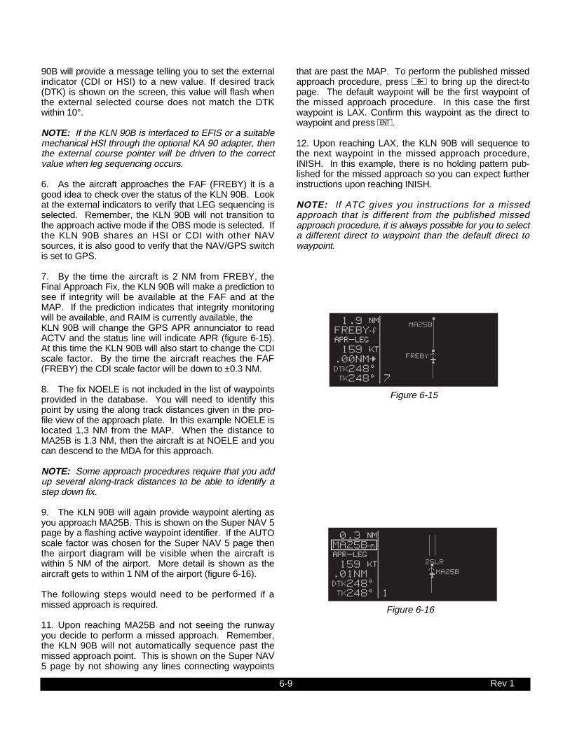
6-9
90B will provide a message telling you to set the externalindicator (CDI or HSI) to a new value. If desired track(DTK) is shown on the screen, this value will flash whenthe external selected course does not match the DTKwithin 10°.
NOTE: If the KLN 90B is interfaced to EFIS or a suitablemechanical HSI through the optional KA 90 adapter, thenthe external course pointer will be driven to the correctvalue when leg sequencing occurs.
6. As the aircraft approaches the FAF (FREBY) it is agood idea to check over the status of the KLN 90B. Lookat the external indicators to verify that LEG sequencing isselected. Remember, the KLN 90B will not transition tothe approach active mode if the OBS mode is selected. Ifthe KLN 90B shares an HSI or CDI with other NAVsources, it is also good to verify that the NAV/GPS switchis set to GPS.
7. By the time the aircraft is 2 NM from FREBY, theFinal Approach Fix, the KLN 90B will make a prediction tosee if integrity will be available at the FAF and at theMAP. If the prediction indicates that integrity monitoringwill be available, and RAIM is currently available, the KLN 90B will change the GPS APR annunciator to readACTV and the status line will indicate APR (figure 6-15).At this time the KLN 90B will also start to change the CDIscale factor. By the time the aircraft reaches the FAF(FREBY) the CDI scale factor will be down to ±0.3 NM.
8. The fix NOELE is not included in the list of waypointsprovided in the database. You will need to identify thispoint by using the along track distances given in the pro-file view of the approach plate. In this example NOELE islocated 1.3 NM from the MAP. When the distance toMA25B is 1.3 NM, then the aircraft is at NOELE and youcan descend to the MDA for this approach.
NOTE: Some approach procedures require that you addup several along-track distances to be able to identify astep down fix.
9. The KLN 90B will again provide waypoint alerting asyou approach MA25B. This is shown on the Super NAV 5page by a flashing active waypoint identifier. If the AUTOscale factor was chosen for the Super NAV 5 page thenthe airport diagram will be visible when the aircraft iswithin 5 NM of the airport. More detail is shown as theaircraft gets to within 1 NM of the airport (figure 6-16).
The following steps would need to be performed if amissed approach is required.
11. Upon reaching MA25B and not seeing the runwayyou decide to perform a missed approach. Remember,the KLN 90B will not automatically sequence past themissed approach point. This is shown on the Super NAV5 page by not showing any lines connecting waypoints
Rev 1
that are past the MAP. To perform the published missedapproach procedure, press D to bring up the direct-topage. The default waypoint will be the first waypoint ofthe missed approach procedure. In this case the firstwaypoint is LAX. Confirm this waypoint as the direct towaypoint and press E.
12. Upon reaching LAX, the KLN 90B will sequence tothe next waypoint in the missed approach procedure,INISH. In this example, there is no holding pattern pub-lished for the missed approach so you can expect furtherinstructions upon reaching INISH.
NOTE: If ATC gives you instructions for a missedapproach that is different from the published missedapproach procedure, it is always possible for you to selecta different direct to waypoint than the default direct towaypoint.
0.3 oqMA25Bñ|z{-«} | 159 uv.01NM |ûü248^|†ü248^|1
25LR
MA25B
Figure 6-16
1.9 oqFREBYî|z{-«} | 159 uv.00NM=|ûü248^|†ü248^|7
FREBY
MA25B
Figure 6-15
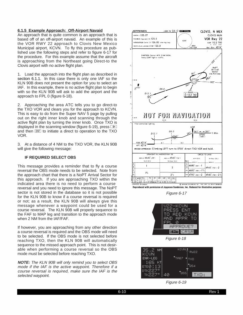
6-10
6.1.5 Example Approach: Off-Airport NavaidAn approach that is quite common is an approach that isbased off of an off-airport navaid. An example of this isthe VOR RWY 22 approach to Clovis New MexicoMunicipal airport, KCVN. To fly this procedure as pub-lished use the following steps and refer to figure 6-17 forthe procedure. For this example assume that the aircraftis approaching from the Northeast going Direct-to theClovis airport with no active flight plan.
1. Load the approach into the flight plan as described insection 6.1.1. In this case there is only one IAF so theKLN 90B does not present the option for you to select anIAF. In this example, there is no active flight plan to beginwith so the KLN 90B will ask to add the airport and theapproach to FPL 0 (figure 6-18).
2. Approaching the area ATC tells you to go direct-tothe TXO VOR and clears you for the approach to KCVN.This is easy to do from the Super NAV 5 page by pullingout on the right inner knob and scanning through theactive flight plan by turning the inner knob. Once TXO isdisplayed in the scanning window (figure 6-19), press Dand then E to initiate a direct to operation to the TXOVOR.
3. At a distance of 4 NM to the TXO VOR, the KLN 90Bwill give the following message:
IF REQUIRED SELECT OBS
This message provides a reminder that to fly a coursereversal the OBS mode needs to be selected. Note fromthe approach chart that there is a NoPT Arrival Sector forthis approach. If you are approaching TXO within theindicated area there is no need to perform a coursereversal and you need to ignore this message. The NoPTsector is not stored in the database so it is not possiblefor the KLN 90B to know if a course reversal is requiredor not; as a result, the KLN 90B will always give thismessage whenever a waypoint could be used for acourse reversal. The KLN 90B will properly sequence tothe FAF to MAP leg and transition to the approach modewhen 2 NM from the IAF/FAF.
If however, you are approaching from any other directiona course reversal is required and the OBS mode will needto be selected. If the OBS mode is not selected beforereaching TXO, then the KLN 90B will automaticallysequence to the missed approach point. This is not desir-able when performing a course reversal so the OBSmode must be selected before reaching TXO.
NOTE: The KLN 90B will only remind you to select OBSmode if the IAF is the active waypoint. Therefore if acourse reversal is required, make sure the IAF is theselected waypoint.
Rev 1
|V22-KCVN|PRESS ENT|TO ADD KCVN|AND APPR TO|FPL 0| APPROVE? ent CRSR
Figure 6-18
35.2 oqKCVN |xy-«} | 165 uváà0:13|ûü227^|†ü227^|40 TXOì
KCVN
TXO
Q55
Q54
TA87
RW22
Figure 6-19
Figure 6-17

6-11
4. If a course reversal is required, then upon reachingTXO perform the appropriate holding pattern entry andset the inbound course on the external CDI or HSI. In thisexample the inbound course is 241°. At this point theKLN 90B works very similar to a conventional VOR/DME.
5. Once established on the inbound course of 241°,switch back to the Leg mode. When Leg mode is selectedthe FAF is automatically made the active waypoint whenthe IAF and the FAF are at the same waypoint.
NOTE: It is mandatory that the unit be in LEG mode withthe FAF as the active waypoint before crossing the FAFto activate the approach active mode and change to ±0.3NM scale factor. The CDI scale factor changes from ±1.0NM to ±0.3 NM over the two miles to the FAF. Delayingthe switch from OBS to Leg mode compresses the scalefactor change. This will make the transition more abrupt.If the switch from OBS to Leg is delayed too long it willnot be possible for the KLN 90B to change to theapproach active mode.
6. When the aircraft is 2 NM from the FAF, the KLN 90Bwill verify that the proper integrity is available. If integritymonitoring is available for the approach, then the KLN 90B will change to the Approach Active mode. Thiswill be annunciated on the external approach statusannunciator as well as on the KLN 90B. The CDI scalefactor will also start to change from ±1.0 NM to ±0.3 NM.
7. Upon reaching TXO, the KLN 90B will automaticallysequence to RW22, the missed approach point.
8. The fix at 8 DME from TXO along the final approachcourse is not included in the waypoints that come fromthe database. Since the distance that the KLN 90B is giv-ing you is distance TO the MAP, you will need to mentallyfigure out when the aircraft has reached this point. This isdone by looking at the along track distances given in theplan view of the approach. In this case the fix is 4.1 NMfrom RW22. Upon reaching this distance you candescend to the MDA for this approach.
Rev 1
If a missed approach is required for this approach, thenthe following steps would be required.
9. The published missed approach procedure for thisapproach is to make a climbing left turn to 5700 feet andproceed direct to the TXO VOR. In this case TXO will bethe default direct to waypoint when D is pressed. Thisis the desired waypoint so press E to confirm the way-point and proceed direct to the VOR.
NOTE: If ATC gives you instructions for a missedapproach that is different from the published missedapproach procedure, it is always possible for you to selecta different direct to waypoint than the default direct towaypoint.
10. As the aircraft approaches TXO you will need toselect OBS mode to stop waypoint sequencing anddefine the inbound course for the holding pattern. If youdo not select the OBS mode before the aircraft is within 4NM of the holding point, then the KLN 90B presents amessage reminding you to select the OBS mode.
NOTE: If another attempt at the approach is desiredafter holding, it is necessary to manually change theactive waypoint. When the FAF and the missed approachholding point are at the same place then the KLN 90B willautomatically change the active waypoint to the FAFwhen you change from OBS to LEG. Make sure to makethis change as soon as possible to ensure the approachactive mode becomes the active mode.

6-12
6.1.6 Example Approach: Radar VectorsFor this example we will use the same approach that wasused in the previous section except this approach will beconducted with the help of radar vectors from approachcontrol. The aircraft will be assumed to be arriving fromthe West, although this does not change the way theapproach will be flown using the KLN 90B.
1. The approach has been selected and entered into theflight plan and the aircraft is going direct to KCVN (Clovis,New Mexico Municipal) as described in section 6.1.5.
2. As soon as ATC mentions radar vectors you shouldimmediately start to think of the OBS mode. Once givenradar vectors, change the active waypoint to TXO andselect the OBS mode. Note that it is not important whatorder these events take place. It is just as effective tochange to OBS mode and then change the active way-point as it is to change the active waypoint and thenswitch to OBS mode.
3. Next, change the selected course on the CDI or HSIto the final approach course. For this example, theinbound course is 241°. It is now possible to watch yourprogress on the Super NAV 5 page and anticipate whenyou will be given new headings to fly (figure 6-20).
4. Once established on the inbound course, you willneed to change back to the Leg mode to allow for properapproach operation and automatic leg sequencing. Forbest performance, the change back to Leg mode shouldbe made before the aircraft is 2 NM from the FAF.
NOTE: It is mandatory that the unit be in LEG mode withthe FAF as the active waypoint before crossing the FAFto activate the approach active mode and change to ±0.3NM scale factor. The CDI scale factor changes from ±1.0NM to ±0.3 NM over the two miles to the FAF. Delayingthe switch from OBS to Leg mode compresses the scalefactor change. This will make the transition more abrupt.If the switch from OBS to Leg is delayed too long it willnot be possible for the KLN 90B to change to theapproach active mode.
5. The rest of this approach would be flown using thesame steps as presented in section 6.1.5.
Rev 1
4.5 oqTXOî |âä241 | 123 uv4.3NM=|òô241^|†ü061^|5
TXO
Figure 6-20

6-13 Rev 1
THIS PAGE INTENTIONALLY LEFT BLANK

6-14
6.1.7 Example Approach: On-Airport NavaidAnother common type of approach is an approach that isbased on an on-airport navaid. These could be eitherVOR or NDB approaches. An example of this type ofapproach is the VOR RWY 24 approach to Bowmanairport in Louisville, Kentucky (Figure 6-21). The airportidentifier for this airport is KLOU.
For this example assume that the aircraft is approachingKLOU from the Nabb VOR.
1. After passing the Nabb VOR, you are told to expectthe VOR 24 approach at KLOU. You load the approachusing the procedure described in section 6.1.1.
2. When the distance from the present position to thedestination airport reaches 30 NM, the KLN 90B will auto-matically arm the approach mode. The CDI scale factorwill transition to ±1.0 NM and the KLN 90B will providemore sensitive integrity monitoring.You also press A toupdate the barometric information.
3. When the aircraft is 4 NM from the BQM VOR, theKLN 90B will give a message reminding you to select theOBS mode. The OBS mode is required for the procedureturn. In this case, don’t select the OBS mode until afterthe KLN 90B has sequenced past BQM-i and madeFF24-f the active waypoint. (This will keep you from hav-ing to manually activate FF24-f while in the OBS mode.)After passing BQM, select the outbound course of 068°on the external CDI or HSI.
4. With the OBS mode selected and FF24 as the activewaypoint, it is possible to fly the procedure turn. Allowenough distance past FF24 to complete the procedureturn and still be 2 NM away before reaching the FAF.After completing the heading portion of the procedureturn, change the selected course to the inbound course of248° on the external CDI or HSI.
5. Once established on the inbound course the Legmode will again need to be selected so that properapproach operation and waypoint sequencing will occur.
NOTE: It is mandatory that the unit be in LEG mode withthe FAF as the active waypoint before crossing the FAFto activate the approach active mode and change to ±0.3NM scale factor. The CDI scale factor changes from ±1.0NM to ±0.3 NM over the two miles to the FAF. Delayingthe switch from OBS to Leg mode compresses the scalefactor change. This makes the transition more abrupt. Ifthe switch from OBS to Leg is delayed too long it will notbe possible for the KLN 90B to change to the approachactive mode.
Rev 1
1.1 oqBQMì |âä068 | 107 uv.01NM=|òô068^|†ü071^|2 FF24î
FF24
BQM
24
06
Figure 6-22
Figure 6-21

6-15
6. When the aircraft is 2 NM from the FAF, the KLN 90Bwill verify that the proper GPS integrity is available. Ifintegrity monitoring is available for the approach, then the KLN 90B will change to the Approach Active mode. Thiswill be annunciated on the external approach statusannunciator as well as on the KLN 90B. The CDI scalefactor will also start to change from ±1.0 NM to ±0.3 NM.
7. Normal waypoint alerting will occur as the aircraftpasses the final approach fix. The leg from the finalapproach fix to the missed approach point will becomeactive and the CDI scale factor will remain at ±0.3 NM. Ifthe AUTO scale factor was selected on the Super NAV 5page, then the scale factor will zoom in on the airport asthe aircraft gets closer and closer to the missed approachpoint. Eventually the map scale changes to 1 NM and therunway diagram becomes visible on the map.
The following steps are followed if a missed approach isrequired.
8. The missed approach instructions call for a climbingleft turn to a heading of 110° until intercepting the 061°inbound course to the missed approach holding fix,SCUMY. To fly this with the KLN 90B it will be necessaryto put the KLN 90B into the OBS mode and makeSCUMY the active waypoint. Change the selected courseon the external CDI or HSI to 061°.
9. Once the aircraft reaches SCUMY, you will need toperform a holding pattern entry suitable for this holdingpattern and set the selected course to 241° for theholding pattern.
Rev 1

6-16
6.1.8 Example Approach: DME ArcDME arc procedures with the KLN 90B are completelydifferent from using traditional VOR and DME equipment.Don’t worry though because DME arc procedures usingthe KLN 90B are also easier than using traditional equip-ment. This is because the KLN 90B provides left/rightguidance around the arc. No more having to watch dis-tance in one place and radial in another!
A DME arc is really a whole bunch of initial approachfixes placed one next to each other to form an arc. Veryrarely do you actually fly to the beginning of an arc.Instead, the flight path of the aircraft generally intersectsthe arc at some point. Once the aircraft is near the arc, itis then possible to turn so that the arc distance is main-tained until time to turn to the inbound fix.
The following example will show how DME arc proce-dures are flown using the KLN 90B. This exampleapproach will be to use the VOR RWY 12 approach toOwatonna, Minnesota, KOWA. The approach plate forthis approach is in figure 6-23. Assume that the aircraft isapproaching from the North.
1. ATC assigns the VOR RWY 12 approach. Turn tothe APT 8 page for KOWA to select the approach. Youselect the VOR 12 approach and the KLN 90B presentsthe IAF selection page (figure 6-24).
2. There are five choices for the IAF. Three of thesechoices you can recognize but the other two, D040L andD220L, are unfamiliar and not shown on this chart.These two waypoints are the database identifiers for theends of the arc. D040L means DME arc point, 040 is theradial which the waypoint lies, and L indicates the dis-tance of the arc. L is the twelfth letter of the alphabet sothe L indicates that this is a 12 DME arc. In a similarmanner D220L can also be decoded. In this example theaircraft is approaching from the north so the D040L IAFwill be selected.
3. The KLN 90B knows that this point is associated witha DME arc. Once an arc waypoint is chosen, the KLN90B determines what radial of the reference VOR the air-craft is presently located on. A waypoint is created that islocated at the intersection of the present radial and theDME arc. This waypoint is the first waypoint in the list ofwaypoints presented on the APT 8 page before loadingthe approach into the flight plan (figure 6-25). This way-point is named using the same convention discussedearlier.
NOTE: If the present radial from the reference VOR isoutside of the defined arc, then the KLN 90B will defaultto the beginning of the arc.
CAUTION: The KLN 90B does not take into accountthe geometry of the active flight plan when determin-ing the arc intercept point. This point is defined
Rev 1
Figure 6-24
|V12-KOWA| 1 D011Lì| 2 D310L| 3 FOWî| 7 FOWï|LOAD IN FPL ent CRSR
Figure 6-25
|V12-KOWA|IAF 1 ALMAY| 2 D040L| 3 D220L| 4 FOW| 5 MKT ent CRSR
Figure 6-23

6-17
solely on the present radial and the defined arc dis-tance from the reference VOR. For this reason it isbetter to delay selecting approaches that containDME arcs until the aircraft is closer to the destination.
4. With the cursor over LOAD IN FPL, press E. Theapproach will be loaded into the active flight plan just likeany other approach would be.
5. After the approach is loaded into the flight plan theKLN 90B may give the message:
REDUNDANT WPTS IN FPL EDIT ENROUTE WPTS AS NECESSARY
Examine the flight plan and, if practical, observe theSuper NAV 5 page to make sure that the sequence ofwaypoints does not have any unnecessary legs in it.
6. The KLN 90B will now provide guidance to the arcintercept point. The Super NAV 5 page displays the entirearc on the screen. The portion that is between thebeginning of the arc and the arc intercept is drawn with adashed line. The part that is between the arc interceptpoint and the end of the arc is drawn with the normal solidline (figure 6-26).
7. In some cases ATC may provide radar vectors to thearc. The KLN 90B provides a means to define a newintercept point based on the current track of the aircraftover the ground. This can be done from either the SuperNAV 5 page or from the FPL 0 page. The dashed linedisplayed on the Super NAV 5 page will help you to deter-mine if ATC is giving you correct vectors.
• From the Super NAV 5 page, pull out the right inner knob to bring up the waypoint scanning window.
• Turn the right inner knob until the first waypoint ofthe arc is displayed, D011L in this example. For approaches this will have a small (i) appended to the waypoint name. If the recalculation is to be done from the FPL 0 page, then turn on the left cursor and move it over the first waypoint of the arc.
• From either page press @. This will change the waypoint to read MOVE? (figure 6-27). If it is desired to recompute the arc intercept point then press E. If a new arc intercept point is not desired then press @ again.
• If E was pressed, then the KLN 90B will calculate an arc intercept point based on the present track of the aircraft over the ground.
Rev 1
Figure 6-26
3.0 oqD011Lì|arm-«}| 142 uv.11NMÇ|ûü191^|âë011^|5
D011L
Figure 6-27
3.0 oqD011Lì|arm-«}| 142 uv.11NMÇ|ûü191^|âë011^|5 MOVE ?
D011L

6-18
NOTE: If the present track does not intercept the arc,then the KLN 90B will display NO INTRCPT in thescratch pad area of the screen.
8. When the aircraft approaches the arc the KLN 90Bwill provide waypoint alerting and turn anticipation to jointhe arc.
9. Once established on the arc the KLN 90B providesleft/right guidance relative to the curved arc. Distance tothe active waypoint is the distance from the present posi-tion to the active waypoint, NOT the distance along thearc. Refer to Appendix A for the geometry of the arc.
10. During the arc, the desired track will be constantlychanging. To help you keep the orientation correct theSuper NAV 5 will automatically display DTK on the sixthline. It is not possible to change this to something elsewhile on the arc. The value displayed for the desiredtrack will flash when the difference between the CDI orHSI and the current desired track is greater than 10°.
11. Some DME arcs have defined radials that serve asstep down fixes. These points are not stored in thedatabase. To help you determine your position relative tothese step-down points along the arc, the KLN 90B willdisplay a new value on the bottom line of the display onthe Super NAV 5 page. This new bit of information isdenoted by the letters ARC followed by three numbers.The three numbers represent the current radial that youare on relative to the reference VOR/DME. It is not possi-ble to select any other type of information to display onthis line like you normally can. The arc radial is forced intothis position when the aircraft is 30 NM from the arc. Thearc display is shown in figures 6-26 or in figure 6-27. Justwatch this value and when it reads the same as one ofthe step-down points you can descend as necessary.This particular example does not have such points, butthere are quite a few approaches that do.
NOTE: Autopilot performance may not be satisfactory ifcoupled in the NAV mode while flying the arc. Manyautopilots were never designed to fly curved paths. Ifautopilot performance is not satisfactory while flying DMEarcs, select the HDG mode and keep changing the head-ing bug to keep the D-bar centered.
12. As the aircraft approaches the end of the arc, theKLN 90B will provide waypoint alerting and turn anticipa-tion to the next leg.
13. When the aircraft is 2 NM from FOW VOR, the FAF,the KLN 90B will attempt to transition to the approachactive mode. Since the DME arc procedure is flownentirely in the LEG mode the only possible problem wouldbe if the integrity monitoring did not check out.
Rev 1

6-19
14. The visual descent point is identified by the alongtrack distance to the MAP to be 1.5 NM. When the air-craft reaches this point (figure 6-28), and the runway envi-ronment is in sight, it is possible to descend for a landing.
If a missed approach is needed use the following steps:
15. The missed approach calls for a climb to 2000 andthen a left turn direct to FOW. Since the KLN 90B will notautomatically sequence past the MAP, the KLN 90B willprovide the correct guidance for the climb.
16. Once 2000 feet has been reached press D, themissed approach holding point will be the default direct towaypoint. Press E to confirm the direct to waypoint andproceed to the FOW VOR.
NOTE: If ATC gives you instructions for a missedapproach that is different from the published missedapproach procedure, it is always possible for you to selecta different direct to waypoint than the default direct towaypoint.
17. The OBS mode will need to be selected to accom-plish the holding pattern. If this is not done before theaircraft getting 4 NM from FOW, the KLN 90B will providea message reminding you to select the OBS mode.
NOTE: If another attempt at the approach is desiredafter holding, it is necessary to manually change theactive waypoint. When the FAF and the missed approachholding point are at the same place then the KLN 90B willautomatically change the active waypoint to the FAFwhen you change from OBS to LEG. Make sure to makethis change as soon as possible to ensure the approachactive mode becomes the active mode.
6.1.9 Approach ProblemsVery rarely there will be a problem with the integrity of theGPS system while you are conducting non-precisionapproaches with the KLN 90B. In some cases the KLN90B will determine that there will not be sufficient integritymonitoring for the leg between the FAF and the MAP, orRAIM is not currently available. In these cases the KLN90B will not go into the approach active mode and willpresent the following message:
RAIM NOT AVAILABLEAPR MODE INHIBITEDPREDICT RAIM ON STA 5
In these cases you will not be able to finish the approachbecause there is insufficient integrity monitoring. The STA5 (Status 5) page provides a means for you to predictwhen RAIM will be available.
To perform a RAIM prediction on the STA 5 page twopieces of information are needed. The first is the locationthat the prediction will be for and the second is the timefor the prediction.
Rev 1
1.5 oqRW12ñ |z{-«} | 101 uv.06NM=|ûü130^|†ü129^|2
RW1212
Figure 6-28

6-20
The destination waypoint will, by default, be the missedapproach point of an approach loaded in the flight plan. Ifthere is no approach in the flight plan, then the defaultwaypoint is the last waypoint in the active flight plan. Ofcourse it is possible for you to enter any waypoint in thisfield.
The time used for the RAIM prediction will be the currentETA to the destination airport or the MAP. This time isautomatically updated by the KLN 90B so there is usuallyno need to enter a value. If you are making a RAIM calcu-lation for planning purposes, it is also possible to enter atime in this field. An important point about this time is thatthe time used for RAIM prediction is always in the futureand limited to 24 hours from the present time. Forexample, if the time is now 19:30 and the time entered forthe ETA is 18:30, then the prediction will be made for thenext day not one hour ago.
To perform a manual RAIM calculation use the followingprocedure.
1. Turn the left outer and inner knobs to select the STA5 page.
2. Press the left C. The cursor will be over the DESTfield.
3. Enter the desired waypoint identifier by using the leftinner and outer knobs just like you do for any otherwaypoint entry.
4. Once the desired waypoint identifier is entered pressE (figure 6-29). Press E again if the waypointinformation is correct.
5. The cursor will now be over the ETA field. Use the leftinner knob to enter the desired hour. Note that thecurrent time zone is displayed below the ETA field. Usethe left outer knob to move the cursor over the minutesfield. Use the inner and outer knobs to select tens of min-utes and single minutes as required. When the desiredtime is selected press E. The RAIM calculations willstart.
6. The RAIM calculation will usually take a few secondsbefore an answer is reached. During this time the STA 5page will be as shown in figure 6-30.
7. Once the RAIM calculation is complete, the STA 5page will indicate the results of the test. This is donegraphically in a bar graph format. The center of the bargraph represents the ETA that you entered in step 5.Each bar represents 5 minutes of time. The RAIMcalculation is good for ±15 minutes of the ETA. Bars thatare above the line indicate that RAIM is available andbars below the line indicate when RAIM is not available.
An example is shown in figure 6-31. Notice in the figurethat the first four bars are below the line and the otherthree are above the line. This means that RAIM is notavailable at the ETA, nor during the 15 minutes prior tothe ETA. RAIM is predicted to be available five minutesafter the ETA and the next 10 minutes. By showing thetimes when RAIM will be available it is possible for you toalter your ETA to ensure that there will not be any RAIMproblems.
Even more rare will be the case when the KLN 90Bcannot provide sufficient integrity monitoring or if there isan actual satellite failure while the aircraft is on the legfrom the FAF to the MAP. In these cases the KLN 90Bwill FLAG the navigation solution and a missed approachwill have to be flown. The KLN 90B will provide thefollowing message:
PRESS GPS APR FOR NAV
This message is telling you to cancel the approach modeby pressing the external switch/annunciator. This willchange the unit to the approach-arm mode andnavigation information will be restored.
Rev 1
Figure 6-29
RAIM STATUS|DEST: 3K1 |ETA: 14:35| CST| COMPUTING |-15 0 +15|STA 5|
Figure 6-30
RAIM STATUS|DEST: 3K1 |ETA: 14:35| CST| èèèèééé |-15 0 +15|STA 5|
Figure 6-31
RAIM STATUS| 3K1DEST: 3K1 |ALVA MUNETA: --:--| CST| êêêêêêê |N 36^46.39'-15 0 +15|W 98^40.20' CRSR| ent|APT 1

6-21
6.2 SID/STAR PROCEDURES
The database in the KLN 90B also contains the pilot NAVSIDs (Standard Instrument Departures) and STARs(Standard Terminal Arrival Routes) for the primarydatabase coverage area (see Chapter 2 for databasecoverage areas). SID/STAR procedures stored in thedatabase can only be considered accurate as long as thedatabase is current. Even though the database containsSID and STAR procedures, there is a lot of informationthat is not included in the database. Therefore, the paperchart is still the primary source of information. For exam-ple, many procedures require the aircraft to fly to a certainaltitude, along a heading until intercepting a course, andmany other procedures that the KLN 90B can not auto-matically accomplish. Many procedures require pilotaction to ensure that the proper path is flown over theground. The main purpose of loading a SID or a STARinto the active flight plan is to provide you with a quickway of loading a potentially large number of waypoints.
SID and STAR procedures can be as challenging to flyas some approaches are. Therefore it is mandatory thatyou are comfortable with the operation of the KLN 90Bbefore attempting to fly SID and STAR procedures. Inparticular, flight plan operation and the OBS mode shouldbe second nature to you.
NOTE: There are some SID/STAR procedures in theworld that are not suited for the operational characteris-tics of the KLN 90B. These procedures are not includedin the database and therefore the waypoints that make upthese procedures would have to be entered manually. Itis good preflight practice ensure that the KLN 90B con-tains anticipated procedures for the flight.
SID and STAR procedures are stored with the airport forwhich they apply. SID and STAR procedures areaccessed through the APT 7 page. If there are both SIDsand STARs for a given airport, then there will be two APT7 pages, one to select a SID and the other to select aSTAR. This is indicated by APT+7. It is also possible tohave only a SID or only a STAR in which case there isonly one APT 7 page.
SID and STAR procedures are defined in three parts.The parts are the SID or STAR name (e.g., PORTE9), atransition (e.g., Fellows), and a runway specific compo-nent (e.g., RW 01L). The APT 7 pages lead you throughthe selection process.
6.2.1 Selecting A SIDUse the following procedure to select a SID. Some stepsmay not be necessary depending on the procedure thatyou wish to fly. For this example, the PORTE NINEdeparture from San Francisco International (KSFO) willbe used.
Rev 1

6-22
1. Select KSFO on one of the airport pages (figure 6-32). If you are operating from an active flight plan youcan use the ACT 7 page for KSFO by scanning throughthe active flight plan (see section 4.2.3).
2. If not already displayed, rotate the right inner knobuntil the APT 7 page appears as in figure 6-33. This willallow the selection of SID procedures.
3. Turn the right cursor on by pressing the right C,and rotate the right outer knob until the flashing cursor isover PORTE9 (figure 6-34). With the cursor overPORTE9, press E.
4. The KLN 90B will now ask which runway that you willbe using. For this example select RW01B (figure 6-35)and press E.
5. The last bit of information needed to define this SID isthe transition. This example uses the Fellows transition.To select the Fellows transition, move the cursor down toFLW (figure 6-36) and press E.
6. The KLN 90B now presents a list of waypoints thatmake up the SID. Review these waypoints if desired. Ifthe waypoints look correct then press E with the cursorover LOAD IN FPL to load the SID into the active flightplan (figure 6-37).
7. The KLN 90B will then add the SID procedure afterthe airport reference point in the active flight plan (figure6-38). If the airport reference point is not included in theactive flight plan, then the KLN 90B will ask to add thiswaypoint to the active flight plan.
Section 6.2.4 gives the actions required to fly this SID.
6.2.2 Selecting A STARThe steps required to select a STAR are very similar tothose required to select a SID. The only difference is theorder of the steps to define the STAR and where theSTAR is loaded into the flight plan. The steps required todefine Acton Four arrival with the Wink transition serve asan example of how to select a STAR. This STAR is to theDallas/Fort Worth International airport (KDFW).
Use the following procedure to select a STAR:
1. Select KDFW on one of the airport pages (figure 6-39). If you are operating from an active flight plan youcan use the ACT 7 page for KDFW by scanning throughthe active flight plan (see section 4.2.3).
2. Turn to the APT 7 page for KDFW. Make sure thatthe words SELECT STAR are displayed near the top ofthe screen.
Rev 1
Figure 6-33
; 1:KSFO | KSFO PORTE9-SID|SELECT SID< 2.SFO04 | 1 CUIT1 3.PORTE | 2 DUMB5 4.PESCA | 3 EUGEN5 7.FLW |10 STINS6FPL 0 enr-leg APT+7
Figure 6-38
| KSFO|SAN FRANCIS|C INT|CL B|N 37^37.14'|W122^22.49' APT 1
| KSFO|SELECT SID| 1 CUIT1| 2 DUMB5| 3 EUGEN5|10 STINS6 APT+7
| KSFO|SELECT SID| 5 OFFSH2| 6 PORTE9| 7 REBAS2|10 STINS6 ent CRSR
|PORTE9-SID|RUNWAY| 1 RW01B| 2 RW10B| 3 RW19B| 4 RW28B ent CRSR
|PORTE9-SID|TRANSITION| 1 AVE| 2 CZQ| 3 FLW| 4 PXN ent CRSR
|PORTE9-SID| 1 SFO04| 2 PORTE| 3 PESCA| 6 FLW|LOAD IN FPL ent CRSR
| KDFW|DALLAS/FT|WORTH|CL B|N 32^53.82'|W 97^02.55' APT 1
Figure 6-32
Figure 6-35Figure 6-34
Figure 6-37
Figure 6-39
Figure 6-36

6-23
3. Turn the right cursor on by pressing the right C,and, if necessary, rotate the right outer knob until theflashing cursor is over the desired STAR. With the cursorover AQN4 (figure 6-40), press E.
4. The KLN 90B will now ask which transition you wantto use. For this example select INK (figure 6-41) andpress E.
5. In some cases, the STAR procedure requires you toselect a specific runway. To select a specific runwaymove the cursor over the desired runway and press E.In this example the STAR does not require a specific run-way so the KLN 90B skips this step.
6. The KLN 90B now presents a list of waypoints thatmake up the STAR (figure 6-42). Review these way-points if desired and then press E to load the STAR intothe active flight plan.
7. The KLN 90B will then add the STAR procedurebefore the airport reference point in the active flight plan(figure 6-43). If the airport reference point is not includedin the active flight plan, then the KLN 90B will ask to addthis waypoint to the active flight plan.
NOTE: It is not possible to load a SID or STAR into aflight plan other than FPL 0. Furthermore, SID and STARprocedures are deleted from FPL 0 after the power is offfor more than 5 minutes.
6.2.3 Editing a SID or STARFrom the proceeding two examples you may havenoticed that SID and STAR procedures have procedure“headers” just as approaches do. It is possible to usethese headers to delete and change the entire procedurejust like is done with approach procedures. One differ-ence between SID and STAR procedures andapproaches is that it is possible to add waypoints to anddelete waypoints from the published procedure. To helpyou differentiate between approaches (no adding or delet-ing waypoints allowed) and SID or STAR procedures(adding and deleting waypoints allowed) the waypointnumber has a period (.) next to it instead of a blankspace. The period also differentiates a SID or STARwaypoint from a “regular” waypoint that has a colon (:)next to the waypoint number.
To add an individual waypoint in the SID or STAR proce-dure use the following steps:
1. Use the left knobs to select the FPL 0 page on the leftside of the screen.
2. Turn the left cursor on by pressing the left C.Rotate the left outer knob as necessary to position thecursor over the waypoint identifier which you desire tofollow the waypoint being added.
Rev 1
; 1:KELP | KDFW AQN4-ãåç |SELECT STAR< 2.INK | 1 AQN4 3.PHILS | 2 BOIDS4 4.TQA | 3 BUJ6 14:KDFW | 4 SCY6FPL 0 enr-leg APT+7
Figure 6-43
Figure 6-41
Figure 6-42
Figure 6-40
| KDFW|SELECT STAR| 1 AQN4| 2 BOIDS4| 3 BUJ6| 4 SCY6 ent CRSR
|AQN4-ãåç|TRANSITION| 1 ABI| 2 EDNAS| 3 INK| ent CRSR
|AQN4-ãåç| 1 INK| 2 PHILS| 3 TQA|12 CREEK|LOAD IN FPL ent CRSR

6-24
3. Use the left inner and outer knobs in the normalmanner to define the desired waypoint.
4. Press E to display the waypoint page for thisidentifier. If the waypoint is correct, then press E a sec-ond time to confirm the waypoint page. The new waypointis added to the waypoints that make up the SID or STARprocedure.
To delete an individual waypoint in a SID or STARprocedure use the following steps:
1. Use the left knobs to select the FPL 0 page on the leftside of the screen.
2. Rotate the left outer knob to place the cursor over thewaypoint to be deleted.
3. Press @. The letters DEL (delete) will appear tothe left of the identifier and a question mark will appear tothe right of the identifier.
4. If this is the desired waypoint to delete, then pressE. If it is not the desired waypoint, press @.
NOTE: Adding waypoints to or deleting waypoints fromSID or STAR procedures does not change the way thatthey are stored in the published database.
To change or delete an entire SID or STAR procedurefrom the active flight plan use the following steps:
1. Use the left knobs to select the FPL 0 page on the leftside of the screen.
2. Turn the left cursor on by pressing the left C. Movethe cursor over the SID or STAR procedure header byusing the left outer knob.
3. With the cursor over the procedure header, press Eto change the SID or STAR or press @ and then E todelete the entire procedure.
NOTE: Any waypoints manually added to a SID or STARwill be deleted if the SID or STAR is changed or deletedusing the above procedure.
Rev 1

6-25
6.2.4 Example of a SID ProcedureTo illustrate the use of the KLN 90B with a SID, the PorteNine departure loaded into the flight plan in section 6.2.1will be used. This procedure is one of the more difficultthat you are likely to come across. Most procedures arenot this difficult, but this SID serves as a good examplefor what steps to take when you encounter a difficult pro-cedure.
To fly this procedure use the following steps and refer tothe chart for this SID (figure 6-44):
1. Load the SID as described in section 6.2.1.
2. The procedure states “Intercept and proceed via SFOR-350, cross the 4 DME fix at or above 1600’...”. Toaccomplish this portion of the SID, put the KLN 90B intothe OBS mode with SFO04 as the active waypoint andmake 350° the selected course. It is easiest to accom-plish these steps before take-off. SFO04 is the waypointthat is 4 DME from the SFO VORTAC and 350° is theinbound course to this fix. After take-off climb to 1600’ asrequired by the SID.
3. Once the aircraft reaches SFO04, turn left to a head-ing of 200°. At this point it is necessary to manuallychange the active waypoint to “PORTE”. This is doneeasily from either the Super NAV 5 page or from the FPL0 page. In either case, once PORTE is highlighted inreverse video, press D to bring up the direct to page.
4. Press E to confirm PORTE as the direct towaypoint.
5. Change the selected course to the new value of 135°.This setup will take the aircraft to the PORTE intersectionas directed by the SID.
6. Before reaching PORTE, change back to the Legmode to enable automatic waypoint sequencing. Oncethe aircraft reaches PORTE the KLN 90B willautomatically sequence to the next waypoint, PESCA.
7. After passing PESCA, the procedure calls for a 090°heading until intercepting the OSI R-116. Onceestablished on the 116° radial proceed to the WAGESintersection. To do this with the KLN 90B, change back tothe OBS mode and make sure that WAGES is the activewaypoint. Set the selected course to 116°.
8. Before reaching WAGES change to the Leg mode.This will allow automatic waypoint sequencing uponreaching WAGES.
9. There is an altitude restriction marked with an “x” onthe chart. The name of this point is 26FLW. 26FLWmeans that the waypoint is 126 NM from the FLWVOR/DME. Make sure to meet any altitude requirementsupon reaching this waypoint.
10. Once the aircraft reaches FLW, proceed on with therest of the flight plan as required.
Rev 1
Figure 6-44

6-26
6.2.5 Example of a STAR ProcedureTo illustrate the use of the KLN 90B with STARprocedures the steps required to fly Acton Four arrival toDallas/Fort Worth International will be shown in this sec-tion. This procedure is considerably simpler than the SIDexample shown in section 6.2.4.
For this example assume that the aircraft departs from ElPaso, Texas and files for the Acton Four arrival with theWink transition. Use the following steps to fly thisprocedure with the KLN 90B and refer to the chart for thisSTAR (figure 6-45):
1. Load the STAR into the flight plan as described insection 6.2.2.
2. This STAR is very simple and the KLN 90B will auto-matically guide the aircraft along the proper route until theAQN VOR.
3. Long before reaching AQN examine this procedureand notice that there are two different routes dependingon what type of aircraft is flying the STAR. Turbojets fly toCREEK intersection while non-turbojets fly to RENDYintersection. The database in the KLN 90B has thesequence of waypoints for the turbojet procedure NOTthe sequence for non-turbojets.
NOTE: It is extremely rare to have a different path overthe ground for turbojets and non-turbojets, but be sure tocross check with your paper charts.
If the aircraft you are flying in is a turbojet, then fly the restof the STAR as depicted on the chart with no changes tothe flight plan. If the aircraft is not a turbojet then followthese steps:
4. Turn to the FPL 0 page and delete the following way-points: MARKUM, BRYAR, HULEN, FLATO, andCREEK. To do this turn on the left cursor and rotate theleft outer knob until the cursor is over one of the abovewaypoints.
5. Press @ and then E to delete a waypoint.
6. Repeat steps 4 and 5 until all of the unnecessarywaypoints are deleted.
7. Now add JERRY, CRESN, and RENDY to FPL 0 byusing the left inner and outer knobs and E asnecessary.
8. The rest of the STAR can now be flown.
Rev 1
Figure 6-45

Rev 1A-1
BRG - Bearing to waypoint (degrees)DA - Drift Angle (degrees) - not displayed on KLN 90BDIS - Distance to waypoint (nm)DTK - Desired Track (degrees)OBS - Selected CourseGS - Groundspeed (nm/hr)HDG - Heading (degrees)POS - Present positionTK - Actual Track (degrees)WPT - WaypointXTK - Cross Track Error Correction (nm) displayed as
“FLY L 2.3 nm”ETE - Estimated Time Enroute (hrs:min)ETA - Estimated Time of ArrivalARC - Radial from reference VOR when executing an
approach procedure with a DME arc
APPENDIX A - NAVIGATIONAL TERMS
NORTH
BRG
OBS
OFF TRACKOBS Mode
WIND
POS
XTK
TK
HDG
GS
NORTHACTIVE WPT
DA
DIS/E
TE/ETA
WPT 1
WIND
POS
HDGDA
NORTH
WPT 2
DIS/ETE/ETA/GS
ON TRACKLeg Mode
BRG
TK
DTK
WPT 1
WIND
POS
XTK
TK
HDG
DTK
BRG
GS
NORTH
WPT 2
DA
OFF TRACKLeg Mode
DIS/E
TE/ETA
WPT 1
WIND
POS
XTK
TK
HDG
BRG
GS
NORTH
WPT 2
DA
OFF TRACK-DME ARCLeg Mode
DIS/E
TE/ETA
ARC
ReferenceVOR
NORTH
NORTH
DTK

Rev 1
THIS PAGE INTENTIONALLY LEFT BLANK
A-2

Rev 1B-1
The following is a list of the messages that can appearon the Message page. When the message promptappears, press MSG to view the message page. Seesection 3.5 for an explanation of the Message page.
ACTV ANNUNCIATOR FAIL - This message appearswhen there is a failure of the KLN 90B ACTV annuncia-tor drive circuitry. To determine if the approach mode isactive you will need to look at the status line of the KLN 90B because the annunciator will not be working ifthis message has been given. Service the KLN 90B assoon as possible.
ADJ NAV IND CRS TO 123° - (Adjust NavigationIndicator Course to 123°) When this message appears,the pilot should select the suggested course on the HSIor CDI. When the KLN 90B is in the Leg mode, thismessage occurs at the beginning of turn anticipation(prior to reaching the active waypoint) if the upcomingcourse change is greater than 5°. See section 4.2.2.
This message will also appear in installations where theKLN 90B is interfaced with an HSI such that the KLN 90B has the capability of reading the selectedcourse from the HSI. In the Leg mode it will appearwhenever the difference between the HSI’s selectedcourse and the KLN 90B’s desired track (DTK) isgreater than five degrees.
ADJ NAV IND CRS - (Adjust Navigation IndicatorCourse) This message will appear in installations wherethe KLN 90B is interfaced with EFIS or with a mechani-cal HSI through the optional KA 90 adapter. This mes-sage appears when the difference between the HSI’sselected course and the KLN 90B’s selected course(OBS) is greater than 0.5°. This usually happens onlywhen the external indicator is not slewed to a new valuedefined by the KLN 90B. Check the interface betweenthe KLN 90B and the external indicator to determine theproblem.
AIRSPACE ALERT - This message appears when theestimated time to enter a special use airspace isapproximately 10 minutes or when the distance from anarea of special use airspace is less than two nauticalmiles. See section 3.10.
ALTITUDE FAIL - This message appears if the altitudeinput to the KLN 90B fails. The altitude related featuresof the KLN 90B will be disabled. There also may bemore RAIM related messages since altitude is notavailable to help in the integrity calculations. Have theinstallation checked as soon as practical to determinethe cause of the problem.
APT ELEVATION UNKNOWN - (Airport ElevationUnknown) This message appears if the elevation of theairport which would otherwise be used for the heightabove airport alert is unknown.
ARINC 429 AIR DATA FAIL - This message appears ifthe KLN 90B is interfaced with an air data system hav-ing ARINC 429 outputs and the outputs are not beingreceived correctly by the KLN 90B.
ARINC 429 OUTPUT FAIL - This message appearswhen the ARINC 429 output fails an internal test.Anything depending on the KLN 90B’s ARINC 429 out-put, such as the EHI 40/50 electronic HSI and somenavigation graphics displays, should not be used.
ARM ANNUNCIATOR FAIL - This message appearswhen there is a failure of the KLN 90B ARM annunciatordrive circuitry. To determine if the approach mode isarmed you will need to look at the status line of the KLN90B because the annunciator will not be working if thismessage has been given. Service the KLN 90B as soonas possible.
ARM GPS APPROACH - If the approach ARM modehas been disarmed then the KLN 90B will remind you toARM the approach mode when the aircraft is 3 NM fromthe Final Approach Fix. Arm the approach mode if it isdesired to use the KLN 90B for conducting an approach.
BAD SATELLITE GEOMETRYAND RAIM NOT AVAILABLE - This message appearsonly when the unit is in the approach active mode, RAIMis not available and the satellite geometry has furtherdegraded to cause more uncertainty of the aircraft posi-tion. This message may be followed by a NAV flag (in acouple of minutes) if conditions continue to degrade.
BAD SATELLITE GEOMETRYSEE EPE ON STA 2 PAGE - This message will occurafter receiving a notice that RAIM is not available. Thismeans that the geometry of the satellites is such thatthe possible error in position is greater than allowed forIFR use. Cross check the position of the aircraft withother means of navigation every 15 minutes to verifythat the position is still accurate.
APPENDIX B - MESSAGE PAGE MESSAGES

Rev 1B-2
BATTERY LOW: SERVICEREQUIRED TO PREVENT LOSS OF USER DATA - This message appears whenthe KLN 90B’s internal battery is low and needs replac-ing at an authorized Bendix/King service center. Thebattery should be replaced within a week to prevent theloss of all user-defined data including waypoints, airportremarks, flight plans, etc. Typical battery life is approxi-mately three to five years.
CHECK ACTV ANNUNCIATOR - This messageappears when an overcurrent condition is detected onthe ACTV annunciator output. It is usually indicative ofa failure of the wiring between the KLN 90B and theACTV annunciator. To determine if the approach modeis active you will need to look at the status line of theKLN 90B because the annunciator will not be working ifthis message has been given. Have the installationchecked to determine the problem.
CHECK ARM ANNUNCIATOR - This messageappears when an overcurrent condition is detected onthe ARM annunciator output. It is usually indicative of afailure of the wiring between the KLN 90B and the ARMannunciator. To determine if the approach mode isarmed you will need to look at the status line of the KLN 90B because the annunciator will not be working ifthis message has been given. Have the installationchecked to determine the problem.
CHECK MSG ANNUNCIATOR - (Check MessageAnnunciator) This message appears when an overcur-rent condition is detected on the MSG annunciator out-put. It is usually indicative of a failure of the wiringbetween the KLN 90B and the MSG annunciator. Todetermine if message alerting is being given you willneed to look at the KLN 90B because the annunciatorwill not be working if this message has been given.Have the installation checked to determine the problem.
CHECK WPT ANNUNCIATOR - (Check WaypointAnnunciator) This message appears when an overcur-rent condition is detected on the WPT annunciator out-put. It is usually indicative of a failure of the wiringbetween the KLN 90B and the WPT annunciator. Todetermine if waypoint alerting is being given you willneed to look at the KLN 90B because the annunciatorwill not be working if this message has been given.Have the installation checked to determine the problem.
DATA BASE CHECKSUM ERR - (Data BaseChecksum Error) This message appears if the database fails an internal test when the KLN 90B is turnedon. The most likely cause of the message is a faileddata base cartridge.
DATA BASE OUT OF DATE ALL DATA MUST BECONFIRMED BEFORE USE - This message appearswhen the data base is out of date as a result of a dateand time entered on the SET 2 page or Self-Test pageor as a result of a pilot-entered date being overridden bya date from the GPS receiver.
EEPROM FAILURE: IC_____EXTERNAL D-BAR INVALID - This message appearsin the event a specific internal test fails. The blanks willcontain the designator of one of the electrical compo-nents. Record the data before turning the unit off inorder to assist maintenance personnel. Do not use anexternal HSI or CDI while it is driven by the KLN 90B.The rest of the KLN 90B is still usable including theinternal CDI; however, the page displays may not becentered on the screen.
IF REQUIRED SELECT OBS - This message appearswhen the aircraft is 4 NM from a waypoint which couldbe used as the basis for either a procedure turn or aholding pattern and the unit is in the LEG mode. Selectthe OBS mode when flying procedure truns or holdingpatterns. This message is advisory only. If no procedureturn is required then no action is required.
INSIDE SPC USE AIRSPACE[name and type of special use airspace][ATC responsible] [Vertical boundaries] - (Inside SpecialUse Airspace) This message appears when the air-craft’s present position is inside an area of special useairspace. See section 3.10.
MAGNETIC VAR INVALIDALL DATA REFERENCEDTO TRUE NORTH - This message appears when themagnetic variation is invalid due to operation outside ofthe data base magnetic variation area without having apilot-entered magnetic variation. See section 5.12.
MSG ANNUNCIATOR FAIL - (Message AnnunciatorFailure) This message appears when there is a failureof the KLN 90B MSG annunciator drive circuitry. Todetermine if message alerting is being given you willneed to look at the KLN 90B because the annunciatorwill not be working if this message has been given.Service the KLN 90B as soon as possible.
NAV SUPER FLAG FAILURE - This message appearswhen an internal test fails for a specific NAV flag output.The KLN 90B is still usable, but anything connected tothe super flag (such as some HSIs and autopilots)should not be used with the KLN 90B.

RAIM NOT AVAILABLEAPR MODE INHIBITEDPREDICT RAIM ON STA 5 - This message appearswhen integrity monitoring (RAIM) is predicted to not beavailable at either the FAF or the MAP. The KLN 90Bwill not allow the unit to go into the approach activemode until conditions improve. Turn to the STA 5(Status 5) page to perform a RAIM prediction. The STA5 page will give an indication of how long it will be untilRAIM is available so that the approach can be flownusing the KLN 90B (see section 6.1.9 for how to performa RAIM prediction).
RAIM POSITION ERRORCROSS CHECK POSITION - This message means thatthe unit has detected a problem with one of the satellitesand the position can not be assured to be within IFRlimits for the particular mode of flight. Cross check theposition of the aircraft with other means of navigationevery 15 minutes to verify that the position is stillaccurate.
RAIM NOT AVAILABLECROSS CHECK POSITION - This message appearswhen there are not enough received GPS satellitesignals to compute integrity (RAIM). Cross check theposition of the aircraft with other means of navigationevery 15 minutes to verify that the position is stillaccurate.
RCVR HARDWARE ERROR:_____- (ReceiverHardware Error) This message appears when the KLN 90B fails a specific internal test for the GPSreceiver. The blank will contain a numerical value whichmay provide assistance to maintenance personnel.
RECYCLE POWER TO USECORRECT DATA BASE DATA - This messageappears when the date entered on the Self-Test page isbefore the data base effective date and the date enteredlater on the SET 2 page is after the data base effectivedate, or vice versa. Turn the KLN 90B off and back onso that the correct data base data is utilized.
REDUNDANT WPTS IN FPL EDIT ENROUTE WPTS AS NECESSARY - This message appears after the
pilot inserts an approach or SID/STAR procedure in theflight plan and the KLN 90B determines that some way-points that were in the flight plan are no longer needed.Examine the active flight plan and remove those way-points that occur both in the enroute and the approachor SID/STAR sections of the flight plan.
RS-232 DATA ERROR - This message appears whenan error is detected in the received RS-232 data suchas from a fuel management or air data system.
Rev 1B-3
NO RCVR DATA - (No Receiver Data) This messageappears when the KLN 90B fails a specific internal testfor the GPS receiver. This failure will prevent the unitfrom providing any navigation capability.
NO RS-232 DATA - This message appears when noinput is received on the RS-232 input (such as from afuel management or air data system).
OBS WPT > 200NM (OBS Waypoint Greater Than 200NM) This message appears when the KLN 90B is in theOBS mode and the distance to the active waypoint ismore than 200 nautical miles. The system will performnormally; however, at this distance the D-Bar will beextremely sensitive to changes in selected course.
OTHER WAYPOINTS DELETED - This messageappears when the message “WAYPOINT _____DELETED” would be effective for more than ten way-points.
POSITION DIFFERS FROMLAST POSITION BY > 2NM - (Position Differs FromLast Position By Greater Than 2 NM) This messageappears when the GPS sensor first reaches the NAVmode if the new position differs from the position whenpower was turned off by more than two nautical miles.
POSITION OFWPT HASCHANGED - (Position of Waypoint Has Changed) Thismessage appears when either the latitude or the longi-tude of a waypoint used in a flight plan or the activewaypoint has changed by more than .33 minutes as aresult of updating the database. This message is dis-played on the left side of the screen while the waypointpage corresponding to the waypoint which changed isdisplayed on the right side of the screen.
POSITIONS OF OTHERWAYPOINTS HAVE CHANGED - This messageappears when the above message “POSITION OF WPTHAS CHANGED” would be effective for more than tenwaypoints.
PRESS ALT TO SET BARO - This message appearswhen the approach mode is armed. Press the ALT but-ton to update the baro informantion for proper integritymonitoring.
PRESS GPS APR FOR NAV - This message appearsafter the NAV flag has been set due to a RAIM problemwhile the unit is in the approach mode. By pressing theGPS APR button, the unit will be able to restorenavigation information so that you can conduct a missedapproach based on navigation information provided bythe KLN 90B.

RS-232 OUTPUT ERROR - This message appearswhen the RS 232 output fails an internal test. Anythingconnected to the RS 232 output bus, such as somemoving map displays and ELTs (for position reporting),will not be fully functional. Do not use moving map dis-plays that depend on the KLN 90B’s RS 232 output ifthis message is displayed.
SATELLITE COVERAGEINADEQUATE FOR NAV - This message appearswhen the received GPS signals are not adequate fornavigation. Occasions when this message will be dis-played include when there are an insufficient number ofsatellites (including altitude input) or when the satellitegeometry is inadequate for accurately determining posi-tion within 3.8 nautical miles.
SET FUEL ON BOARDON OTH 5 IF NECESSARY - This message appearswhen the KLN 90B determines that it is interfaced with acompatible Shadin fuel flow computer that allows theKLN 90B to set the fuel on board. The pilot should turnto the OTH 5 page to enter the current fuel on board forproper fuel computations (see section 5.10).
SYSTEM TIME UPDATEDTO GPS TIME - The message appears when the KLN 90B system time is automatically updated to GPStime by more than 10 minutes.
USER DATA LOST - This message appears when theunit determines that the internal memory backup batteryis dead or that some other internal failure has occurredwhich has caused all user-entered data including way-points, flight plans, airport remarks, etc., to be lost.
VNV ALERT- (Vertical Navigation Alert) This messageappears when a VNAV operation has been programmedon the NAV 4 page and the estimated time to start theclimb or descent is approximately 90 seconds. Thismessage serves as notification to select the NAV 4page so that the VNAV operation may be executed.This message does not appear if the NAV 4 page isalready being displayed. VNAV status can also bedisplayed on the Super NAV 5 page.
WAYPOINT ______ DELETED - This message appearswhen a waypoint used in a flight plan, or the active way-point, no longer exists as a result of updating the database. The blank space is filled in with the waypointidentifier. The waypoint is deleted from flight plans inwhich it was used.
WPT ANNUNCIATOR FAIL - (Waypoint AnnunciatorFailure) This message appears when there is a failureof the KLN 90B WPT annunciator drive circuitry. Todetermine if waypoint alerting is being given you willneed to look at the KLN 90B because the annunciatorwill not be working if this message has been given.Service the KLN 90B as soon as possible.
Rev 1B-4

Rev 1C-1
Status line messages are short operational messagesthat are displayed in the lower center segment of thescreen. (See section 3.3 and figure 3-37). The follow-ing are the status line messages that may appear.
ACTIVE WPT - (Active Waypoint) Appears when youtry to delete a user-defined waypoint on the OTH 3 pageif the waypoint is the active waypoint (waypoint you arenavigating to). Another waypoint must be made theactive waypoint before this waypoint can be deletedfrom the user-defined waypoint list.
CCRS XXX° - (Direct To course XXX°) Appears whenthe KLN 90B is in the OBS mode and is interfaced withan external indicator which the KLN 90B cannot changethe selected course and the pilot performs a Direct-Tooperation. Since the KLN 90B cannot change theselected course to the direct-to course, the KLN 90Bgives you this message telling you the OBS value thatwill take the aircraft direct to the active waypoint.
DUP IDENT - (Duplicate Identifier) Appears when youhave selected a waypoint identifier on one of the way-point type pages if there is more than one waypoint ofthat waypoint type having the same identifier.
ENT LAT/LON - (Enter Latitude and Longitude)Appears when a user-defined waypoint is being created,to remind you to enter the location of the waypoint.
FPL FULL - (Flight Plan Full) Appears when anattempt is made to add a new waypoint to a flight planwhich already contains 30 waypoints and the firstwaypoint is part of the active leg. Change the activewaypoint or delete another waypoint before adding anymore waypoints.
IN ACT LIST - (In Active List) Appears when a user-defined VOR waypoint is the active waypoint if you try tochange the stored magnetic variation of this VOR. Ifyou need to change the magnetic variation of this way-point, you must first make another waypoint active.
INVALID ADD - Appears when an attempt is made toadd a new waypoint into the approach. Approachprocedures must be flown as they are retrieved from thedatabase.
INVALID DEL - (Invalid Delete) Appears when anattempt is made to delete an approach waypoint.Individual approach waypoints cannot be deleted, youmust delete (or replace) the entire approach.
INVALID ENT - (Invalid Enter) Appears when you haveattempted to enter data which is not a valid entry. Forexample, trying to enter a date of 30 FEB 92.
INVALID REF - (Invalid Reference) Appears when youattempt to create a reference waypoint on theReference Waypoint page if the waypoint you have cho-sen to use as the reference is not a valid choice. Thewaypoint is not a valid choice if it is impossible to draw aperpendicular line from the waypoint you have enteredto one of the legs of the flight plan. A waypoint is alsoinvalid for use as a reference if the letters A through Zcannot be appended to the waypoint identifier to createa unique identifier. See section 5.5.
INVALID VNV - (Invalid Vertical Navigation) Appearswhen a waypoint identifier has been entered on the NAV4 page if the waypoint identifier is not valid for use in aVNAV operation. For the Enroute-Leg mode, the way-point must be the active waypoint or a waypoint posi-tioned in the active flight plan ahead of the aircraft’slocation. In the Enroute-OBS mode, the waypoint mustbe the active waypoint.
NO ACTV WPT -(No Active Waypoint) Appears whenyou attempt to activate the OBS mode if there is noactive waypoint. To have an active waypoint, a flightplan must be activated or a Direct To operation must beaccomplished.
NO APPROACH - Appears when an attempt is madeto arm the GPS approach mode when there is noapproach loaded into the active flight plan. Load anapproach into the flight plan before trying to arm theapproach mode.
NO APT WPTS - (No Airport Waypoints) Appears whenthe APT type pages have been selected if the KLN 90Bdoesn’t contain a data base cartridge and there are nouser-defined airport waypoints.
NO INT WPTS - (No Intersection Waypoints) Appearswhen the INT type pages have been selected if the KLN90B doesn’t contain a data base cartridge and there areno user-defined intersection waypoints.
APPENDIX C - STATUS LINE MESSAGES

Rev 1C-2
NO INTRCEPT - (No Intercept) Appears when anattempt is made to recalculate the intercept point on aDME arc and the actual track does not intercept with thearc. Change the track (heading) of the aircraft so thatthe actual track does intercept the DME arc and tryagain.
NO NDB WPTS - (No NDB Waypoints) Appears whenthe NDB type pages have been selected if the KLN 90Bdoesn’t contain a data base cartridge and there are nouser-defined NDB waypoints.
NO SUCH WPT - (No Such Waypoint) Appears whenthere is no waypoint in the data base corresponding tothe entered identifier on the Reference Waypoint page.
NO SUP WPTS - (No Supplemental Waypoints)Appears when the SUP type pages have been selectedif the KLN 90B doesn’t contain a data base cartridgeand there are no user-defined supplemental waypoints.
NO VOR WPTS - (No VOR Waypoints) Appears whenthe VOR type pages have been selected if the KLN 90Bdoesn’t contain a data base cartridge and there are nouser-defined VOR waypoints.
OUTDATED DB - (Outdated Database) Appearswhenever the pilot attempts to select an approach fromthe database when the database has expired.
RMKS FULL - (Remarks Full) Appears when anattempt is made to create a user-entered airport remarkon the APT 5 page if 100 user-entered airport remarksalready exist. In order to create additional airportremarks, some existing remarks must be deleted on theOTH 4 page as described in section 3.11.6.
RWY MISSING - (Runway Missing) Appears when theAirport 3 (APT 3) page runway diagram shows some,but not all, of the runways at the selected airport. Thisoccurs if the data base contains runway threshold posi-tion data for only some of the runways at the selectedairport.
USED IN FPL - (Used In Flight Plan) Appears whenyou try to delete a user-defined waypoint on the OTH 3page if the waypoint is used in a flight plan. Either thiswaypoint must be deleted from the flight plan or theentire flight plan must be deleted before this waypointcan be deleted from the user-defined waypoint list.
USR DB FULL - (User Data Base Full) Appears whenyou attempt to create a user-defined waypoint if the userdata base already contains 250 waypoints. In order tocreate additional user-defined waypoints, it will first benecessary to delete existing user-defined waypoints onthe OTH 3 page.

Rev 1D-1
STATE ABBREVIATIONS
ABBREVIATION STATE
AK AlaskaAL AlabamaAR ArkansasAZ ArizonaCA CaliforniaCO ColoradoCT ConnecticutDC District of ColumbiaDE DelawareFL FloridaGA GeorgiaIA IowaID IdahoIL IllinoisIN IndianaKS KansasKY KentuckyLA LouisianaMA MassachusettsMD MarylandME MaineMI MichiganMN MinnesotaMO MissouriMS MississippiMT MontanaNC North CarolinaND North DakotaNE NebraskaNH New HampshireNJ New JerseyNM New MexicoNV NevadaNY New YorkOH OhioOK OklahomaOR OregonPA PennsylvaniaRI Rhode IslandSC South CarolinaSD South DakotaTN TennesseeTX TexasUT UtahVA VirginiaVT VermontWA WashingtonWI WisconsinWV West VirginiaWY Wyoming
CANADIAN PROVINCE ABBREVIATIONS
ABBREVIATION PROVINCEAB AlbertaBC British ColumbiaMB ManitobaNB New BrunswickNF NewfoundlandNS Nova ScotiaNW Northwest TerritoryON OntarioPE Prince Edward IslandPQ QuebecSK SaskatchewanYK Yukon
COUNTRY ABBREVIATIONS
ABBREVIATION COUNTRYAFG AfghanistanAGO AngolaAIA Anguilla I.ALB AlbaniaANT Antarctica/Netherlands
Antilles/ArubaARE United Arab EmiratesARG ArgentinaASM American/Western SamoaATG Antigua/BarbudaAUS AustraliaAUT AustriaBDI BurundiBEL BelgiumBEN BeninBFA Burkina FasoBGD BangladeshBGR BulgariaBHR BahrainBHS BahamasBHU BhutanBLZ BelizeBMU BermudaBOL BoliviaBOS Bosnia and HerzegoviaBRA BrazilBRB BarbadosBRN BruneiBWA BotswanaCAF Central African RepublicCAN CanadaCHE SwitzerlandCHL Chile/Easter I.CHN ChinaCIV Ivory Coast
APPENDIX D - ABBREVIATIONS

Rev 1D-2
CMR CameroonCNR Canary IslandsCOG CongoCOK Cook IslandsCOL Colombia/San AndresCRI Costa RicaCRO CroatiaCSK CzechoslovakiaCUB CubaCYM Cayman IslandsCYP CypressDEU GermanyDJI DjiboutiDMA DominicaDNK DenmarkDOM Dominican RepublicDZA AlgeriaECU EcuadorEGY EgyptERI EritreaESP SpainETH EthiopiaFIN FinlandFJI Fiji/TongaFLK Falkland IslandsFRA FranceGAB GabonGBR United KingdomGHA GhanaGIB GibraltarGIN GuineaGLP Guadeloupe/MartiniqueGMB GambiaGNB Guinea-BissauGNQ Equatorial GuineaGPV Cape VerdeGRC GreeceGRD GrenadaGRL GreenlandGTM GuatemalaGUF French GuianaGUY GuyanaHKG Hong KongHND HondurasHTI HaitiHUN HungaryIDN IndonesiaIND IndiaIOT British Indian Ocean TerritoryIRL IrelandIRN IranIRQ IraqISL IcelandISR IsraelITA ItalyJAM JamaicaJOR JordanJPN Japan/OkinawaJTN Johnston Island
KEN KenyaKHM Cambodia/KampucheaKIR Kiribati/Tuvalu/Phoenix I./Line I.KNA St. Kitts/NevisKOR KoreaKWT KuwaitLAO LaosLAT LatviaLBN LebanonLBR LiberiaLBY Liby/SPA JamahiriyaLCA St. LuciaLKA Sri LankaLSO LesothoLUX LuxembourgMAC MacauMAR MoroccoMDG Madagascar/Comoros/
Mayotte I./ReunionMDV MaldivesMEL MelillaMEX MexicoMHL Marshall IslandMID Midway IslandMLI MaliMLT MaltaMNP Mariana IslandsMOL MoldovaMOZ MozambiqueMRT MauritaniaMSR Monserrat I.MUS MauritiusMWI MalawiMYR MyanmarMYS MalaysiaNAM NambiaNCL New CaledoniaNER NigerNGA NigeriaNIC NicaraguaNIU Niue IslandNLD NetherlandsNOR NorwayNPL NepalNRU NauraNZL New ZealandOMN OmanPAC Oakland OTCA (PACIFIC)PAK PakistanPAN PanamaPCI Caroline Island/MicronesiaPER PeruPHL PhilippinesPNG Papua New GuineaPOL PolandPRI Puerto RicoPRK Korea (Dem. Peoples Republic)PRT Portugal/Azores/Madeira I.PRY Paraguay
Country Abbreviations - Continued

Rev 1D-3
PYF French Polynesia/Society I./Tuamotu
QAT QatarROM RomaniaRWA RwandaSAU Saudi ArabiaSDN SudanSEN SenegalSGP SingaporeSHN Ascension Island/St. HelenaSLB Solomon IslandsSLE Sierra LeoneSLO SloveniaSLV El SalvadorSOM SomaliaSPM St. Pierre/MiquelonSTP Sao Tome/PrincipeSUR SurinameSVK SlovakiaSWE SwedenSWZ SwazilandSYC SeychellesSYR SyriaTCA Turks and Caicos IslandsTCD ChadTGO TogoTHA ThailandTTO Trinidad/TabagoTUN TunisiaTUR TurkeyTWN TaiwanTZA TanzaniaUGA UgandaURY UruguayUSA U.S.A. including Baker IslandsVCT St. VincentVEN VenezuelaVGB Virgin Islands (U.K.)VIR Virgin Islands (U.S.)VNM VietnamVUT VanautuWAK Wake IslandWLF Wallis/Futuna IslandsXJ1 Kazakhstan/KyrgyzstanXJ2 Armenia/GeorgiaXJ3 Ukraine, MoldovaXJ4 Estonia/RussiaXJ5 Belarus/Latvia/Lithuania/RussiaXJ6 Kazakhstan/RussiaXJ7 Kazakhstan/Tajikistan/
Turkmenistan/UzbekistanXJJ AzerbaijanXJR RussiaYEM Yemen (Arab Republic)YUG YugoslaviaZAF South AfricaZAM ZambiaZAR ZaireZWE Zimbabwe
AIR ROUTE TRAFFIC CONTROL CENTER(ARTCC/FIR) ABBREVIATIONS
(Used on CTR 2 Page)
ABBREVIATION ARTCC
ABQ AlbuquerqueACC AccraADD Addis AbabaADE AdelaideADN AdenAKM AkmolaAKT AktyubinskALG AlgiersALM Alma-AtaAMD AmdermaAMM AmmanAMS AmsterdamANA AnadyrANC Anchorage ArcticANC AnchorageANC Anchorage OceanicANK AnkaraANT AntananarivoARK ArkhangelskASH AshkhabadASM AsmaraAST AstrakhanASU AsuncionATF AntofagastaATH AthensATL AtlantaAUC Auckland OceanicAUC AucklandBAG BaghdadBAH BahrainBAK BakuBAL BaliBAN BangkokBAR BarcelonaBAT BatagayBEI BeijingBEL BelemBER BermudaBIA BiakBIS BishkekBLA BlagoveshchenskBLG BelgradeBLO BloemfonteinBOD BodoBOD Bodo OceanicBOG BogotaBOM BombayBOR BordeauxBOS BostonBRA BeiraBRD BrindisiBRE BremenBRI Brisbane
Country Abbreviations - Continued

Rev 1D-4
BRL BerlinBRN BarnaulBRR BarranquillaBRS BrasiliaBRT BeirutBRU BrusselsBRV BratislavaBRY BeryozovoBRZ BrazzavilleBSK BratskBST BrestBUC BucharestBUD BudapestBUJ BujumburaCAI CairoCAL CalcuttaCAM Campo GrandeCAM Central AmericaCAN CanariesCAP CapetownCAS CasablancaCHA ChaybukhaCHE ChelyabinskCHI ChicagoCHO ChokurdakhCHR CherskyCHT ChitaCHU ChulmanCLE ClevelandCOC Cocos IslandCOL ColomboCOP CopenhagenCOR CordobaCRT CuritibaCUR CuracaoDAK DakarDAK Dakar OceanicDAM DamascusDAR DarwinDEL DelhiDEN DenverDES Dar-Es-SalaamDHA DhakaDIK KiksonDOR KornodDSS DusseldorfDUR DurbanDUS DushanbeEDM EdmontonEMI EmiratesENT EntebbeEZE EzeizaFRA FrankfurtFW Ft WorthGAB GaboroneGAN Gander DomesticGAN Gander OceanicGEN GenevaGEO Georgetown
GUA GuangzhouGUY GuayaquilHAN HanoiHAR HarareHAV HavanaHK Hong KongHNR HoniaraHOC HochiminhHON HonoluluHOU HoustonHOU Houston OceanicIND IndianapolisIRK IrkutskISL Isla de PascuaIST IstanbulJAK JakartaJAX JacksonvilleJED JeddahJOH JohannesburgKAB KabulKAM Kamennyi MysKAN KanoKAR KarachiKAT KathmanduKAZ KazanKC Kansas CityKHA KhabarovskKHR KharkovKHT KhatangaKIE KievKIG KigaliKIN KingstonKIR KirenskKIS KisanganiKK Kota KinabaluKL Kuala LumpurKM Khanty-MansiyskKNS KinshasaKO Kzyl-OrdaKOL KolpashevoKOS KostanayKRA KrasnovodskKRS KrasnoyarskKRV KirovKSH KishinauKTM KhartoumKUN KunmingKUR KurganLAH LahoreLAN LanzhouLAP LA PazLAX Los AngelesLIL LilongweLIM LimaLIS LisbonLJU LjubljanaLON LondonLUA LuandaLUB Lubumbashi
Air Route Traffic Control Center (ARTCC/FIR) Abbreviations - Continued

Rev 1D-5
LUS LusakaLVO LvovMAD MadridMAG MagadanMAI MaiquetiaMAL MaleMAN ManilaMAR MarseilleMAU MauritiusMAZ MazatlanMAZ Mazatlan OceanicMDR MadrasMEL MelbourneMEM MemphisMEN MendozaMER MeridaMEX MexicoMGD MagdagachiMIA MiamiMIA Miami OceanicMIL MilanMIN MinneapolisMIR MirnyMLM MalmoMLT MaltaMNC Monction NorthernMNC Monction SouthernMNS ManausMNT MonterreyMOG MogadishuMON MontrealMOS MoscowMRM MurmanskMS Mys ShmidtaMSK MinskMTV MontevideoMUN MunichMUR MurenMUS MuscaNAD Nadi OceanicNAH NahaNAI NairobiNAS NassautNDJ N’DjamenaNIC NicosiaNIK Nikolaevsk-Na-AmureNMY NiameyNOR NorilskNOV NovosibirskNUK NukusNY New YorkNY New York OceanicNZE New ZelandOAK OaklandOAK Oakland OceanicODE OdessaOKH OkhaOMS OmskORN Orenburg
OSK OkhotskOSL OsloPA Punta ArenasPAN PanamaPAP Port Au PrincePAR ParisPE Port ElizabethPEC PechoraPEM PermPEN PenzaPER PerthPET PetersburgPEV PevekPHN Phnom PenhPIA PiarcoPM Port MoresbyPMT Puerto MonttPRA PraguePRM ParamariboPTR Petropavlovsk-KamPV Porto VelhoPYO PyongyangREC RecifeRES ResistenciaREY ReykjavikRIG RigaRIV RivadaviaRMS ReimsROB RobertsROC RochambeauROM RomeROS RostovROV RovaniemiSAI SainshandSAL Sal OceanicSAM SamaraSAN SantiagoSCO ScottishSDO Santo DomingoSEA SeattleSEM SemipalatinskSEY SeychellesSHA ShanghaiSHE ShenyangSHN ShannonSHW Shanwick OceanicSIM SimferopolSIN SingaporeSJU San Juan OceanicSLC Salt Lake CitySLK SalekhardSM Santa Maria OceanicSMR SamarkandSOF SofiaSON SondrestromSTA StavangerSTO StockholmSUK SukhumiSUN Sundsvall
Air Route Traffic Control Center (ARTCC/FIR) Abbreviations - Continued

Rev 1D-6
SUR SurgutSWI SwitzerlandSYD SydneySYK SyktyvkarSYM SeymchanTAE TaeguTAH Tahiti OceanicTAI TaipeiTAL TallinnTAM TampereTAS TashkentTAZ TashavzTBI TbilisiTEH TehranTEL Tel AvivTIK TiksiTIL TilichikiTIR TiranaTOK TokyoTOR TorontoTRI TripoliTRO TrondheimTUN TunisTUR TurukhanskTYU TyumenUFA UfaUJU Ujung BandangULA UlaanbaatarUND UnderhaanURA UralskURU UrumqiVAN VancouverVAR VarnaVEL Velikiye LukiVIE ViennaVIL VilniusVLA VladivostokVNT VientianeVLO VologdaVOL VolgogradVRK VorkutaWAR WarsawWAS WashingtonWEL WellingtonWIN WinnipegWND WindhoekWUH WuhanYAK YakutskYAN YangonYEK YekaterinburgYEN YeniseyskYER YerevanYS Yuzhno-SakhalinskZAG ZagrebZAI ZaireZHK ZhezkazganZUR ZurichZYR Zyryanka
OTHER ABBREVIATIONS USED ON KLN 90BPAGES
80 80 octane fuel100 100 octane fuel100LL 100 octane low lead fuelA Airport waypointAAS Aeronautical advisory serviceABV AboveACQ AcquisitionACT Active flight plan waypointsADJ AdjustAKD Alaska Daylight TimeAKS Alaska Standard TimeALRT Alert areaALT AltitudeANNUN AnnunciatorsAPPR ApproachAPR ApproachAPT AirportARM Approach Arm ModeARVL Arrival (freq)ATD Atlantic Daylight TimeATF Aerodrome traffic frequencyATS Atlantic Standard TimeAWOS Automatic weather observing
stationB BadB BothBARO Barometer (altimeter setting)BEL BelowBRG BearingC CentigradeCAL CalculatorCAL CalibrationCAS Calibrated airspeedCAUT Caution areaCDI Course Deviation IndicatorCDT Central Daylight TimeCL B Class B airspaceCL C Class C airspaceCLR Clearance deliveryCLY ClayCONV ConversionCORD UNIV Coordinated Universal TimeCRS CourseCRSR CursorCST Central Standard TimeCTA Control area (outside USA)CTAF Common traffic advisory
frequencyCTR Center (Air Route Traffic
Control Center)D DME capableD/T Distance/TimeDB DatabaseDEGRD Degraded navigationDEN Density AltitudeDEP Departure
Air Route Traffic Control Center (ARTCC/FIR) Abbreviations - Continued

Rev 1D-7
DEST DestinationDEV Deviation (on external course
devation indicator)DIR Director (freq)DIS DistanceDNGR Danger areaDTK Desired trackDUP DuplicateE EastEDT Eastern Daylight TimeELE ElevationELEV ElevationELV Airport elevationENDUR EnduranceENG EngineENR En routeENT EnterESA Minimum en route safe altitudeEST Eastern Standard TimeETA Estimated time of arrivalETE Estimated time en routeF FahrenheitFAF Final Approach FixFAILR Failure of receiverFF Fuel FlowFLT Flight timeFOB Fuel on boardFP Flight planFPL Flight planFPM Feet per minuteFR FromF REQ Fuel requiredFSS Flight service stationG GPS based approach procedureGAL GallonGDT Greenland Daylight TimeGPS Global Positioning SystemGPS CRS External Leg/OBS switchGRND Ground controlGRV GravelGS GroundspeedGST Greenland Standard TimeH High altitude VORH High pressure oxygenHAD Hawaii Daylight TimeHAS Hawaii Standard TimeHB High pressure bottled oxygenHDG HeadingHDWND HeadwindHRD Hard surfaceHSI Horizontal Situation IndicatorHT HeightI Intersection waypointIAF Initial Approach FixIDENT IdentifierIMP Imperial gallonINACTV InactiveIND Indicated altitude
INIT InitializationINT IntersectionINVRT InvertKG KilogramKT KnotsL LeftL LitersL Low altitude VORL Low pressure oxygenL Runway lighting sunset to sun
riseL FOB Landing fuel on boardLB Low pressure bottled oxygenLB PoundsLDG LandingLEN LengthLPC Runway lighting is pilot controlledLPT Runway lighting is part time or
on requestMACH Mach numberMAHP Missed Approach Holding PointMAP Missed Approach PointMAT Steel mattingMB MillibarsMCOM MulticomMDT Mountain Daylight TimeMF Mandatory frequencyMOA Military operation areaMOD ModeMOGAS Automotive fuelMPH Miles per hourMSA Minimum safe altitudeMSG MessageMST Mountain Standard TimeN NDB overlay approach
procedureN NDB waypointN NorthNAV NavigationNAV A Navigation with altitude aidingNAV D Navigation with data collectionNM Nautical milesNR NearestOBS Omni bearing selectionORS Operational Revision StatusOTH OtherP.POS Present positionPCL Pilot controlled lightingPDT Pacific Daylight TimePOS PositionPOSN PositionPRES PresentPROH Prohibited areaPRS Pressure altitudePST Pacific Standard TimePTAX Pre-taxi clearancePWR PowerR Right
Other Abbreviations Used on KLN 90B Pages - Continued

V VNAV status (on Super NAV 5)V VOR approach overlay
procedureV VOR waypointVERT VerticalVNV Vertical navigation (VNAV)W WeakW WestWARN Warning areaWPT WaypointWRN WarnXTK Cross track error correctionZ Zulu time
Rev 1D-8
R RNAV overlay approach procedure
(R) Radar environment to approach & departure
RAD RadialRAIM Receiver Autonomous Integrity
MonitoringRAMP Ramp/taxi control (freq)RCVR ReceiverRDR Radar (freq)REF ReferenceREQD Required fuelRES Reserve fuelREST Restricted areaRMI Radio magnetic indicatorRMKS RemarksRW RunwayS SouthS Supplemental waypointSAT Static air temperatureSDT Samoa Daylight TimeSEL Selected altitudeSEQ SequenceSET SetupSFT Soft surfaceSHL ShaleSID Standard Instrument DepartureSND SandSNR Signal-to-noise-ratioSNW SnowSPC USE Special Use (airspace)SRCH Search the skySST Samoa Standard TimeSTA StatusSTAR Standard Terminal Arrival RouteSTN StationSUP SupplementalSV Space vehicleSW SoftwareT Terminal VORT Terminal waypointt Relative to true NorthTAS True airspeedTAT Total air temperatureTEMP TemperatureTK Actual trackTLWND TailwindTMA Terminal area (outside USA)TRAN TransitionTRF TurfTRI TripTRNG Training areaTRSA Terminal Radar Service AreaTWR TowerU Undefined class of VORUNIC UnicomUNK UnknownUTC Coordinated Universal Time
(Zulu)
Other Abbreviations Used on KLN 90B Pages - Continued

Rev 1E-1
The KLN 90B utilizes latitude and longitude expressedin degrees, minutes, and hundredths of a minute. Youmay occasionally see a document expressing latitudeand longitude in degrees, minutes, and seconds. Youmay use this table to convert seconds to hundredths ofa minute.
HUNDREDTHS OFSECONDS A MINUTE
00 .0001 .0202 .0303 .0504 .0705 .0806 .1007 .1208 .1309 .1510 .1711 .1812 .2013 .2214 .2315 .2516 .2717 .2818 .3019 .3220 .3321 .3522 .3723 .3824 .4025 .4226 .4327 .4528 .4729 .4830 .5031 .5232 .5333 .5534 .5735 .5836 .6037 .6238 .6339 .6540 .6741 .6842 .7043 .7244 .73
45 .7546 .7747 .7848 .8049 .8250 .8351 .8552 .8753 .8854 .9055 .9256 .9357 .9558 .9759 .98
For Example:
35 deg, 46 min, 24 seconds becomes 35 deg, 46.40 min32 deg, 15 min, 58 seconds becomes 32 deg, 15.97 min
APPENDIX E - SECONDS TO DECIMAL MINUTES

Rev 1
THIS PAGE INTENTIONALLY LEFT BLANK
E-2

Rev 1I-1
AAbbreviations
Airport names 3-26, 3-42ARTCC/FIR D-3Canadian province D-1Country D-1Other KLN 90B D-6State D-1
ACT page (active flight plan waypoints) 4-10Actual track 3-32, 3-34, A-1Air data pages 5-42Airport
City 3-43Communication frequencies 3-45Elevation 3-43Instrument approach capability 3-43Name 3-42Nearest 3-22, 3-37, 3-42Radar capability 3-43Remarks 3-47Runway information 3-43Services 3-48User defined waypoints 5-16
Airport identifiers 2-3Airspeed 5-11, 5-13, 5-43Alerting
Altitude 3-55Height above airport 3-58Special use airspace 3-39Waypoint 3-29, 4-8
Almanac 3-17Altitude
Alerting 3-55Density 5-10, 5-43Indicated 3-55Minimum enroute 3-32Minimum safe 3-32Page 3-55Pressure 5-10, 5-43
Annunciators, remote 3-59, 6-1Antennas 1-2Approach active (ACTV) mode 3-29, 5-32, 5-38, 6-1, 6-3, 6-8Approach armed (ARM) mode 3-29, 5-32, 5-38, 6-1, 6-8Approaches 2-2, 3-49, 5-45, 6-1
Changing 6-7Deleting 6-7Loading 6-4Selecting 6-4
APT 1 page (Airport 1) 3-42
INDEX
APT 2 page (Airport 2) 3-43APT 3 page (Airport 3) 3-43APT 4 page (Airport 4) 3-45APT 5 page (Airport 5) 3-47APT 6 page (Airport 6) 3-48APT 7 page (Airport 7) 3-49, 6-21APT 8 page (Airport 8) 3-49, 6-4, 6-16ARC 6-18, A-1ARTCC (“Center”)
Abbreviations D-3Frequencies 3-52Waypoints 5-25
AUTO map scale 3-36, 6-9Autopilot 6-18
BBaro set 3-5, 3-55, 6-8Battery 2-8Bearing to waypoint 3-31Brightness, see Display brightness
CCAL 1 page (Calculator 1) 5-10CAL 2 page (Calculator 2) 5-11CAL 3 page (Calculator 3) 5-12CAL 4 page (Calculator 4) 5-8, 5-12CAL 5 page (Calculator 5) 5-13CAL 6 page (Calculator 6) 5-14CAL 7 page (Calculator 7) 5-15Canadian Province abbreviations D-1Cancel, see DeleteCanceling Direct to operations 3-29Cartridge, see Data baseCDI 3-4, 3-31, 3-59, 4-9, 6-9CDI scale factor 3-31, 5-37, 5-38, 6-1, 6-2, 6-8“Center” waypoints 5-25Changing
Approaches 6-7SIDs 6-24STARs 6-24
Communication frequenciesAirport 3-55Center (ARTCC) 3-52FSS 3-52
Computer data base, updating 2-3Controls 3-2, 3-11Country abbreviations D-1Course fix 6-6Course reversal 6-10Coverage area

Rev 1I-2
Database 2-1Navigation 3-1
Cross track error 3-32, A-1CTA 3-39, 3-42CTR 1 page (Center 1) 5-25CTR 2 page (Center 2) 5-25Cursor 3-11Customs 3-48
DDatabase
Cartridge 2-3, 2-7Contents 2-1Coverage areas 2-1Currency requirement for approach use 6-1Functions 2-1Operation without cartridge 5-44Page 3-7Update service options 2-8Updating 2-3, 5-46User 2-2, 2-8
Data entry 3-14Date 3-5, 3-53Delete
Airport remarks 3-47Approach 6-7Direct to operation 3-29Flight plans 4-5SID 6-24STAR 6-24User defined waypoints 5-20Waypoints from a flight plan 4-5
Departure time 4-13Desired track 3-32, 3-34, 4-8, 4-12, A-1Direct to operation 3-27, 3-34, 4-10
Canceling 3-29Flight plan 4-10Recenter D-Bar 3-28VNAV 5-7
Display brightness 3-3Display format 3-9Distance 3-31, 3-36, 4-11, A-1D/T 1 page (Distance/Time 1) 5-11D/T 2 page (Distance/Time 2) 5-12D/T 3 page (Distance/Time 3) 5-12D/T 4 page (Distance/Time 4) 5-13DME arcs 6-6, 6-16, 6-17, 6-18Duplicate waypoints 3-15
EEditing
SID 6-23STAR 6-23
EFIS 3-4, 5-34, 6-9Enter prompt 3-10EPE (estimated position error) 5-30Erase, see DeleteESA, see minimum enroute safe altitudeETA (estimated time of arrival) 4-12, A-1ETE (estimated time enroute) 3-31, 3-36, 4-11, A-1
F-f (final approach fix identifier suffix) 6-7FAF (final approach fix) 6-1, 6-2, 6-6Fence 6-7Flight plan(s)
Activating 4-3Active 4-3Adding waypoints 4-4Creating 4-1Deleting flight plans 4-5Deleting waypoints 4-5Inverting 4-3Operation from 4-7Rules 4-1VNAV operation 5-9
Flashing data on screen 3-11Flight time 4-13Fly-by/Fly-over waypoints 4-2Frequencies, see Communication frequenciesFSS frequencies 3-52Fuel availability 3-48Fuel management pages 5-39Fuel on board 5-39Fuel planning 5-3, 5-5, 5-6
GGPS APR switch/annunciator 3-59, 6-1, 6-9GPS CRS switch/annunciator 3-7, 3-59, 5-32, 5-33GPS status 5-29Groundspeed 3-31, 3-36, A-1
H-h (missed approach holding point identifier suffix) 6-7Heading 3-34, A-1Height above airport alert 3-58Holding pattern 6-11, 6-15, 6-19HSI 3-4, 3-59, 4-9, 6-9

Rev 1I-3
I-i (initial approach fix identifier suffix) 6-7IAF (initial approach fix) 6-2
Selecting 6-4, 6-16ICAO identifiers 2-3Initialization 3-17INT page (Intersection page) 3-50Integrity monitoring, see RAIMIntercept DME arc 6-16, 6-17
Moving the intercept point 6-17Interfaces 1-1Intermediate fix 6-6Intersections 3-50Intersection user waypoints 5-18
JJeppesen charts 6-6
KKA 91 antenna 1-2KA 92 antenna 1-2
LLanding fee 3-48Lighting, runway 3-49Loading
Approach 6-4SID 6-22STAR 6-23
Locator outer marker (LOM) 3-50
M-m (missed approach point identifier suffix) 6-7Mach 5-43Magnetic variation 5-44Map display 3-34, 3-36MAP (missed approach point) 3-27, 3-29, 6-2, 6-6, 6-7MAHP (missed approach holding point) 6-2Message page 3-16Messages
Message page 3-16, Appendix BStatus line 3-10, Appendix C
Minimum enroute safe altitude (ESA) 3-33, 5-3, 5-5, 5-6,5-35Minimum safe altitude (MSA) 3-32Missed approach procedure 3-27, 6-11, 6-19MOD pages (MODE) 5-32Modes 3-10, 3-36, 5-32MOVE? 6-17
NNAV 1 page (Navigation 1) 3-31NAV 2 page (Navigation 2) 3-32NAV 3 page (Navigation 3) 3-32NAV 4 page (Navigation 4) 3-34, 5-7NAV 5 page (Navigation 5) 3-34NAV/GPS switch/annunciator 3-59, 6-1Navigation map display 3-34, 3-35Navigation terms A-1NDB page 3-49NDB user waypoints 5-18NDBs, nearest 3-22, 3-37NDBs, on map display 3-37Nearest airports, VORs, NDBs 3-22NOS charts 6-6NO WPT SEQ 6-7Non-precision approaches, see Approaches
OOBS IN 3-4OBS mode 3-32, 4-9, 5-34
In approach procedures 6-10, 6-11, 6-12, 6-14, 6-19
OBS OUT 3-4OBS warning page 3-7Off-airport navaid 6-10On-airport navaid 6-14ORS (Operational Revision Status) 3-3OTH 1 page (Other 1) 3-52OTH 2 page (Other 2) 3-52OTH 3 page (Other 3) 5-20OTH 4 page (Other 4) 3-47OTH 5 page (Other 5) 5-39OTH 6 page (Other 6) 5-41OTH 7 page (Other 7) 5-41OTH 8 page (Other 8) 5-41OTH 9 page (Other 9) 5-43OTH 10 page (Other 10) 5-43Outer markers (OM) 4-50Oxygen availability 3-48
PPage definition 3-9Page selection 3-12Plus sign (+) meaning 3-9Power cycles 5-31Present position 3-8, 3-32Preview of Operation IIProcedure turns 6-14

Rev 1I-4
RRAIM (receiver autonomous integrity monitoring) 6-3, 6-14, 6-15, 6-18
Prediction 6-19, 6-20Radar vectors 6-12, 6-17Receiver status 5-29REF page (Reference waypoint) 5-21Reference waypoints 5-21Removing KLN 90B 2-7Runway fix 6-6Runway information 3-43
SSample trips 3-60, 4-15Satellite status 5-29Scanning active waypoints 3-37, 6-17Scanning waypoints 3-21, 3-24Selected course, see OBS modeSelecting
Approach 6-4IAF 6-2SID 6-22STAR 6-23Transition (SID/STAR) 6-22Waypoints 3-20
Self test page 3-3SET 0 page (Setup 0) 2-4SET 1 page (Setup 1) 3-17, 5-46SET 2 page (Setup 2) 3-53SET 3 page (Setup 3) 3-22SET 4 page (Setup 4) 4-13SET 5 page (Setup 5) 3-58SET 6 page (Setup 6) 4-9SET 7 page (Setup 7) 3-39, 5-10SET 8 page (Setup 8) 3-41SET 9 page (Setup 9) 3-57, 3-59SID (standard instrument departure)
Changing 6-24Deleting 6-24Editing 6-23Example 6-25Loading 6-22Selecting 6-22
SID/STARs 2-2, 3-49, 4-2, 5-45, 6-21SNR (Signal-to-Noise Ratio) 5-29Software status 5-31Special use airspace 3-39, 5-3, 5-5, 5-6STA 1 page (Status 1) 5-29STA 2 page (Status 2) 5-30STA 3 page (Status 3) 5-31STA 4 page (Status 4) 5-31STAR (standard terminal arrival route)
Changing 6-24
Deleting 6-24Editing 6-23Example 6-26Loading 6-23Selecting 6-23
State abbreviations D-1Status line messages 3-10, Appendix CStep-down fix 6-9, 6-18Sunrise/Sunset 5-15SUP page (Supplemental waypoint) 5-18Super NAV 1 page 3-32Super NAV 5 page 3-27, 3-37, 5-9, 5-35, 6-1, 6-6, 6-17Supplemental waypoints 3-51, 5-18Surface, runway 3-44System components 1-1
TTake-home mode 3-3, 3-19, 5-46Temperature conversion 5-13Terminal waypoints 4-10
Names 6-5Time
Actual 3-5, 3-53, 4-13Enroute 3-31, 3-36, 4-11, 4-13Flight 4-13Of arrival 4-12, 4-13Total time of operation 5-31Zones 3-5, 5-14
Time to first fix 3-17TMA 3-39, 3-42Track, see Actual track, see Desired trackTraffic pattern indicator 3-44Transitions (SID/STAR), selecting 6-22TRI 0 page (Trip Planning 0) 5-2TRI 1 page (Trip Planning 1) 5-3TRI 2 page (Trip Planning 2) 5-3TRI 3 page (Trip Planning 3) 5-5TRI 4 page (Trip Planning 4) 5-5TRI 5 page (Trip Planning 5) 5-6TRI 6 page (Trip Planning 6) 5-6Trip planning 5-1True airspeed 5-11, 5-43Turn anticipation 4-8Turn-on 3-3Turn-on page 3-3, 5-28
UUpdating database 2-3, 5-46User database 2-2, 2-8, 3-51User-defined waypoints 5-16UTC, see Time Zones

VVNAV (vertical navigation) 3-36, 5-7Vectors 6-12, 6-17VOR(s)
page 3-49user waypoint 5-18nearest 3-22, 3-37on map display 3-37
WWaypoint alerting 3-29, 4-8Waypoint scanning window 3-37, 6-17Waypoints
Active 3-31“Center” 5-25Duplicate 3-15Identifiers 2-3Nearest 3-22Reference 5-21Selecting by identifier 3-20Selecting by name or city 3-24Selecting by scanning 3-21User defined 2-2, 5-16
Wind 5-12, 5-43
X
Y
Z
Rev 1I-5

Rev 1I-6
THIS PAGE INTENTIONALLY LEFT BLANK