pilot’s guide - jpitech.com revb.pdffor damages that result from the use of this manual or the...
TRANSCRIPT

Pilot’s Guide
VM1000C
VISION MICROSYSTEMS INCORPORATED.
Information: P. O. Box 7033
Huntington Beach, CA 92646
Factory: 3183 B Airway
Costa Mesa, CA 92626
714-557-3805
www.visionmicrosystem.com
(VM1000PG023.doc)
Printed in the United States of America Revision B 8/2007
Copyright © 2007 Vision Microsystems Incorporated
ADVANCED ELECTRONIC INSTRUMENTATION

Table of Contents Section 1 - BASIC OPERATION 1
Buttons 1 Display 2 Dimming control 2 Tachometer Operation 2 Manifold Pressure Operation 3 Percent Power Operation / Calibration 4 Oil System Operation 4 Fuel Computer System Operation 5 Cylinder Watch System Operation 7 EGT Analyzer System Operation 8 Peaking Mode Operation 9 Electrical Monitoring System Operation 10 Autotrack™ System Operation 10 Flight Data Recorder System Operation 12 Air Temperature System Operation 15 Fuel Level System Operation (Optional) 15 Turbo Inlet Temperature System Operation 16
Section 2 - EC100 SYSTEM OPERATION (Optional) 16 Section 3 - INSTALLATION 20
Indicator Installation 20 EC100 System Installation (Optional) 20 Routing the Wiring Harnesses 22 Power Connection 24 Probe and Transducer List 24 Probe Wiring 25 Wiring Markings 26 Exhaust Gas Temperature Probe (EGT) Installation 26 Turbine Inlet Temperature (TIT) Probe Installation (Optional) 27 Cylinder Head Temperature (CHT) Probe Installation 27 Outside Air Temperature (OAT) Probe Installation 28 Induction Air, CDT Probe Installation (Optional) 28 Carburetor (CAT) Probe Installation (Optional) 29 Oil Temperature Probe Installation 29 Oil Pressure Sensor Installation 30 Fuel Pressure Sensor Installation 30 RPM Sensor installation 31 Ammeter Shunt Installation 31 Capacitive Fuel Level Sender Installation 32 Resistive Fuel Level Sender Installation 35

General Fuel Flow Transducer Installation 36 Section 4 - INITIAL SYSTEM SETUP 38
System Setup 38 VisionConfig Setup 38 Built-in VM1000C Setup 47 Mandatory Setup 48 User Setup 50 Percent Power Operation / Calibration 55 Fuel Level System Calibration 56
Section 5 - CONNECTOR PIN ASSIGNMENTS 58 Section 6 - TECHNICAL SUPPORT 59 Index 60
Note: Button numbers are for reference only; buttons on
instrument are not labeled with numbers.

PURCHASER / USER AGREEMENT
The purchaser and/or user, by accepting this equipment, agrees to hold
VISION MICROSYSTEMS INCORPORATED, its owners, assigns,
heirs and employees, free and harmless from all loss, liability or damage
resulting from claims brought by any reason of alleged failure or defect
of any parts supplied by
VISION MICROSYSTEMS INCORPORATED.
VISION MICROSYSTEMS INCORPORATED has made every effort to
document this product accurately and completely. However, VISION
MICROSYSTEMS INCORPORATED assumes no liability for errors or
for damages that result from the use of this manual or the equipment it
accompanies. VISION MICROSYSTEMS INCORPORATED reserves
the right to make changes to this manual and the product at any time
without notice.
****** To receive warranty coverage *******
fill out and return the warranty agreement.

Section 1 - BASIC OPERATION
Buttons
There are five buttons on the front panel, referred to in this manual by—
left to right—numbers 1 through 5. They function differently, depending
on the mode of operation: normal, fueling or setup. Note: Button
numbers are for reference only; buttons on instrument are not labeled
with numbers.
Normal mode buttons:
� � � � � Tap: Peak Find
mode
Hold: Changes
between MAN
and &HP
display
Cycle through
display of each
cylinder temp,
TITs and
hottest
AutoTrack on
or off
Fuel computer
mode (ADD,
GPH/LPH,
REM, HRS,
BRN)
Hold to save
snapshot in
memory
Fueling mode buttons:
� � � � � Decrement
indicated fuel
added to
aircraft
Increment
indicated fuel
added to
aircraft
Enter; accept
the entered
value
Exit without
adding the
value entered
Filled the tanks
Setup mode buttons:
� � � � � Decrement
value being
entered
Increment
value being
entered
Enter; accept
the entered
value
Exit or cancel

Page 2 Vision Microsystems Incorporated
Display
The display is the primary interface between engine instrumentation and
the pilot. See the figure at the end of the table of contents for a depiction
of the display. Optional measurements that are not installed will not be
on the display; they will be blank.
Dimming control
No external connection is needed for dimming. The display is auto-
dimmed by a photocell. However you can adjust the low light level
setting for your conditions. To adjust, initially hold � and � until the
display blinks once. Then use � and � to adjust the brightness. After
setting the new brightness level, do not press any buttons within 5
seconds and your new setting automatically is saved.
Tachometer Operation
The tachometer system provides both a full sweep graphic analog
display and four place digital display. When you start the engine you
will see the analog graph rise in proportion to the engine speed. Full
color range marks and graphics provide you with a quick reference to
monitor normal, caution and red line engine RPM.
RPM
The digital readout provides you with
exact RPM information. The resolution (or
incremental steps) of the digital display is
5 RPM. The high accuracy of the
tachometer will allow you to follow long-
term performance trends of your engine
and prop, such as static maximum rpm,
carburetor heat effectiveness, and typical mag drops. These can be
important indicators of engine and accessory condition. Page 43
Engine Operating Hours
Another feature is the engine hours counter. When the engine is off,
the RPM digital display shows the total accumulated engine hours to
a maximum of 9999.9. Engine hours are accumulated any time RPM

VM1000C Pilot’s Guide Page
3
is greater than 1500. The engine hour counter is initialized by
performing the ENGINE HOURS setup. Page 41
RPM Alert
A warning alert activates whenever
the engines redline is reached (as set
in ENGINE LIMITS menu). The
RPM display will flash until this
condition is corrected. Page 43
Manifold Pressure Operation
The manifold pressure system provides both a full sweep color
graphic analog display and three place digital display. The full color
range marks provide you with a quick reference to when making fast
power changes.
The digital readout provides you with precise information. This
allows very precise power settings to be achieved and is useful for
new induction system designs, or modifications to existing designs,
where repeatability and accuracy is a must.
Note: If %HP icon is shown, then the VM1000C is in percent
power mode. To change to the Manifold Pressure mode simply
hold � in until you see the MAN icon appear.
Manifold Pressure Alert
A warning alert activates whenever the engine’s redline is reached
(as set in ENGINE LIMITS menu section 50.0 user defined engine
parameters). The display will flash until this condition is corrected.
Manifold Pressure Calibration (Optional)
Manifold Pressure can be fine-tuned to your installation in the
appropriate MISCELLANEOUS menu item.

Page 4 Vision Microsystems Incorporated
Percent Power Operation / Calibration
The percent power system provides both a full sweep color graphic
analog display and three place digital display. The full color range
marks provide you with a quick reference when making fast power
changes and the digital readout provides precise information. A
warning alert activates whenever the %HP redline is reached (as set
in ENGINE LIMITS menu). The display flashes until this condition
is corrected. To activate Percent Power mode, simply hold � in until
you see the %HP icon appear. Note: calibration must be initially
performed before use.
Oil System Operation
Both oil pressure and oil temperature are displayed
continuously in two separate full sweep color
graphic and digital areas.
Oil Pressure
As oil pressure rises, the graph size increases
proportionately. The full color range marks let you see at a glance
how close to red line oil pressure you are. The graphic changes color
to match the range marks.
The digital display shows in 1 PSI increments to a maximum of 199.
This is very useful for monitoring typical engine oil pressure trends.
Because of the high accuracy and repeatability of this system, the oil
pressure can be closely monitored for unusual trends. For example, if
you are cruising in a stabilized condition, and the oil pressure starts
to decrease, and oil temperature is increasing, this may indicate an
impending oil system problem.
Oil Pressure Alert
A warning alert activates whenever the engines redline is reached (as
set in ENGINE LIMITS menu 50.4). The display will flash until this
condition is corrected.
Oil Temperature

VM1000C Pilot’s Guide Page
5
Oil temperature is displayed both graphically and digitally. As oil
temperature rises, the digital value and graph size increases
proportionately. Temperature is displayed in either Fahrenheit or
Celsius units (as set in the MISCELLANEOUS menu).
The full color range marks let you see at a glance how close to red
line oil temperature you are.
The digital display shows in 1 degree increments to a maximum of
290 degrees F (143 degrees C). This is very useful for monitoring
typical engine oil cooling system performance.
For new engine installations, you can take advantage of the high
accuracy and repeatability for analyzing the engine oil cooler system
efficiency. If the cooling does not seem to be effective enough, you
can make changes and repeat your tests with the confidence that the
next test data will reflect the results of your changes.
Oil Temperature Alert
If the oil temperature rises above redline (as set in ENGINE LIMITS
menu 50.5), the display will flash until the problem is corrected.
Fuel Computer System Operation
WARNING
Improper use of the fuel flow computer or suspected
erroneous or intermittent operation will give you incorrect
information and may result in premature fuel exhaustion. Do
not use as the primary means of fuel quantity management.
Insure that you understand the operation of this system
completely and carefully monitor its performance before and
during flight. Verify the systems operation for your intended
use by comparing actual burned fuel versus the indicated
burned fuel brn.
Fuel Pressure is displayed both digitally and graphically. As fuel
pressure rises, the graph rises proportionately. Full color operating range
marks and graphics are provided that indicate the normal operating range
of fuel pressure for your engine at a glance. The digital display allows

Page 6 Vision Microsystems Incorporated
you to see small variations and make notations of typical fuel pressure
behavior.
Fuel Pressure Alert warning system will flash should fuel pressure fall
outside of the limits (as set in ENGINE LIMITS menu) for your
particular engine.
Fuel Flow Computer has five modes available. The units can be set to
either gallons, Imperial gallons or liters (as set in the
MISCELLANEOUS menu). Fuel Flow is displayed both digitally and
graphically, but all other measurements are displayed only digitally. All
values are calculated based on the fuel flow sensor and your initial
inputs:
GPH or LPH - Fuel Flow
ADD - ADD fuel to computer memory “tank”
REM - Calculated Fuel REMaining onboard
BRN - Fuel BuRNed since last power-up
HRS - HouRS of fuel remaining
Fuel Remaining Alert occurs when the computed fuel REM is less than
the low fuel remaining value (as set in MISCELLANEOUS) by flashing
the display.
Selecting Fuel Computer Modes
Tap � to select the desired fuel computer mode. The mode is
displayed near the fuel flow readout. The following describes each
mode:
ADD: (flashes) Default mode after powering up and reminds you to
check your fuel REM and add fuel if needed. If you have added fuel to
the aircraft, you must select this mode and add fuel to the fuel
computer’s electronic “tank.” See section below on ADDING FUEL TO
THE COMPUTER. Tap � to leave this mode, if not needed.
GPH / LPH: This mode displays the fuel flow both digitally and
graphically. The graphic section provides you with a quick reference of
the current fuel flow.
REM: This mode displays the current fuel total remaining.

VM1000C Pilot’s Guide Page
7
HRS: This mode displays the calculated hours of fuel remaining
(sometimes referred to as endurance), as a function of the current flow
rate and current fuel remaining (REM) in the computer's memory. It is
digitally displayed in 0.1 hour increments.
BRN: This mode displays the gallons of fuel burned in flight since
system power up.
Adding Fuel to the Fuel Computer
Your fuel computer has a feature that allows you to add fuel
according to how much has been added to the tank(s). Follow the
steps below to ADD fuel to the computer:
STEP 1. Tap � to change the fuel computer mode to show
ADD. It should now be flashing.
STEP 2. Tap � to increment and � to decrement the ADD
value, shown in the digital display, to match the fuel
that was added to the aircraft.
NOTE: To top off the tank(s) just tap � and
the amount will jump to your maximum REM
capacity you programmed initially in setup.
Taping a second time sets value to zero.
STEP 3. If you are satisfied with the entered value, then tap
� to accept it. NOTE: the new total is limited to the
maximum tank capacity value (as set in
MISCELLANEOUS).
NOTE: To exit WITHOUT adding the value
shown, just tap �.
Cylinder Watch System Operation
The Cylinder Watch engine analyzer system
displays all cylinder information both
graphically and digitally. The cylinders are
depicted as a top view that makes
identification easy. The numbering layout is
selected for either the Continental or
Page 8 Vision Microsystems Incorporated
Lycoming engines during setup. Full color graphics make detection
of cylinder operating status easy. The digital display defaults to the
hottest CHT. For example, if CHT 1 is the hottest, the digital
display will show H1 periodically.
Pressing � will cycle through each CHT and the hottest and allow
you to select a different CHT by choosing C1, C2 etc. After power
up or after a peak find operation, the digital display defaults to show
the hottest CHT. Temperature is displayed in either Fahrenheit or
Celsius units (as set in the MISCELLANEOUS menu).
CHT Alert: warning system will flash if a CHT limit is exceeded
(as set in ENGINE LIMITS ). For over temperature both the graphic
and digital will flash. A lowercase h1 would identify CHT1 as
exceeding the maximum redline temperature. For shock cooling a
flashing lowercase c1 would identify CHT1 as exceeding the
maximum cool down rate (as set in MISCELLANEOUS menu).
EGT Analyzer System Operation
The EGT ANALYZER system displays all EGTs graphically. EGT
probes are periodically tested by the system and any probe that is
detected as bad will be shut off. Peaking mode is not allowed if a
bad probe (including a TIT probe) is detected. An EGT over-
temperature (as set in ENGINE LIMITS) will cancel and disallow
peaking mode until corrected.
The system can operate in either of two leaning modes: Rich of
Peak or Lean of Peak. This is selected during initial system setup.
After power up, the EGT digital display defaults to EGT 1 (unless
you have enabled the TIT system - see Turbo Inlet Temperature
System Operation). Periodically the digital display will identify
which EGT you are seeing by showing and E followed by the EGT
number, such as E1 for EGT 1. After you have successfully leaned
the engine (as an example, lets assume it was EGT 2), the digital
readout is locked to that EGT and E1 will change to P2 signifying
that it peaked on EGT 2.
VM1000C Pilot’s Guide Page
9
Tap � to select a different EGT by choosing E1, E2, E3 etc. (Note:
not available when in the peak mode). Temperature is displayed in
either Fahrenheit or Celsius units (as set in the MISCELLANEOUS
menu).
WARNING
Refer to your engine operating manual for the proper
techniques, temperature and precautions for leaning.
Improper leaning may damage your engine!
Peaking Mode Operation
STEP 1: Stabilize
The aircraft engine temps, throttle and rpm. Set the mixture at rich
of peak by verifying all EGT values decrease a few bars when fuel
flow is increased, then allow the engine to stabilize for 5 to 10
seconds.
STEP 2: Find Peak
a. Tap �. Observe that a row of bars appear across the top of
the EGT graphics area signifying peak mode is active.
b. Lean the mixture smoothly so EGT is changing about 3 to 5°F
per second. If significant engine roughness occurs, then a
true peak cannot be found and leaning should be aborted and
mixture returned to a rich value.
c. When peak is found several things happen on the display:
1. The EGT graph flashes for a short period of time and its
top bar comes on identifying the peaked EGT column.
2. Both the EGT and DIF icon are activated.
3. The digital readout now shows DIFferential temperature
(the peak EGT minus current EGT). A positive number
means rich of peak and a negative number means you
are lean of peak.
4. Periodically the actual EGT temperature of the peaked
cylinder is displayed (DIF goes off) allowing you to
monitor it as well.

Page 10 Vision Microsystems Incorporated
STEP 3: Final Mixture Adjustment
a. Now adjust the mixture differential value accordingly to which
leaning mode you initially set up, rich of peak (positive DIF) or
lean of peak (negative DIF).
b. When you have completed leaning, turn off the peak
mode by pressing � again. The DIF icon will go out.
Electrical Monitoring System Operation
VOLTAGE is displayed both graphically and
digitally. Full color range marks provide a quick
reference for fast analysis of voltage levels. As voltage
rises, the graph size increases proportionately.
Voltage Alert: warning system will flash should voltage fall outside
of the limits (as set in ENGINE LIMITS).
AMPERAGE is displayed both graphically and digitally. Full color
range marks provide a quick reference for fast analysis of amperage
levels. As amperage rises, the graph size increases proportionately.
The digital readout displays amperage at 1 amp resolution.
The amp system functions as an alternator load meter displaying
current flow FROM the alternator TO the aircraft electrical system
allowing you to see if a load (such as pitot heat) is really drawing
current when turned on. You should see an increase on the amp
display when you turn on a load, such as pitot heat for example. This
tells you that the pitot heater is drawing power and is probably OK.
By verifying that voltage remains the same, then it can be assumed
that the alternator is supporting the additional load.
Amperage Alert: warning system will flash should amperage fall
outside of the limits (as set in ENGINE LIMITS).
Autotrack™ System Operation
The Autotrack system is a breakthrough in modern engine monitoring
technology. Designed to reduce the pilot's workload by assisting in
the tedious and often overlooked job of monitoring engine
measurements for small but significant deviations, Autotrack adds a

VM1000C Pilot’s Guide Page
11
new level of safety to engine management: a true cockpit Early
Warning System.
Subtle changes may occur in engine measurements that can precede
major problems. These changes are often missed by even the most
attentive of pilots. Autotrack alerts you to these changes allowing you
to analyze the situation and take appropriate action.
When to Use Autotrack
• Climb - Activate during climb to alert you as measurements
change as a function of the prolonged climb.
• Cruise - Activate during cruise to alert you if any measurement
begins to drift from your selected starting point.
• Descent - Activate during descent to alert you to increasing
manifold pressure or percent power and rising EGT due to a
leaning mixture.
How to Use Autotrack
(Note: Autotrack is disabled if peak mode or alarms are active).
STEP 1. STABILIZE the aircraft. Set up your desired power and
mixture condition. Allow the engine time to stabilize
(i.e., engine temps and pressures, etc.).
STEP 2. Tap �. The Autotrack indicator will activate on the
display and the system will begin tracking the engine's
performance from this point
The Autotrack system is now armed and watching for engine
deviation from the point you picked. To cancel, simply tap � to
extinguish the Autotrack indicator. Re-arm again at any time.
Autotrack Alert Indications
If any engine measurement deviates above or below the initial captured
point by more than its allowed difference (as set in ENGINE LIMITS),
the system will flash the graphic element for that measurement and the
Autotrack icon to alert you of this deviation. To shut off the alert
condition, either correct the reason the measurement deviated or tap �
to turn off the Autotrack system.

Page 12 Vision Microsystems Incorporated
Here are a few examples of Autotrack scenarios:
Example 1:
• You arm the Autotrack system then begin a climb.
• Shortly afterwards you get an Autotrack Alert.
• The CHT graphic will flash and you see that the captured
point is lower than the current CHT (temperature is rising).
• You lower the nose to increase cooling thus preventing a
CHT over-temperature.
• You turn Autotrack off then back on to continue
monitoring at the new conditions.
Example 2:
• Autotrack is armed and you are in steady cruise flight.
• During the flight you get an Autotrack Alert.
• You spot that the oil pressure graphic is flashing and the
current oil pressure has dropped.
• The oil pressure has not reached the low redline yet, so
you decide to land at the nearest safe airport and
investigate the reduction in oil pressure.
• You discover that an oil line has been leaking and the loss
of oil quantity caused the reduced pressure!
Flight Data Recorder System Operation
The Flight Data Recorder logs engine data at periodic intervals (your
choice in MISCELLANEOUS setup) and you later download it by
using EZTrends™, the powerful data graphical analysis PC program.
The recorder is fully automatic and records while the engine is
running. Typical storage is greater than 80 operating hours (for a 6
second logging interval). A special mode called Snapshot allows you
to capture data in fast one second intervals, both 180 seconds
BEFORE and AFTER the time of activation, providing detailed
information. Snapshot can be set up to activate automatically on
VM1000C Pilot’s Guide Page
13
certain alarms or manually activated by holding � until the MAN
and RPM field decimal points begin blinking.
DOWNLOAD:
USB Download:
• Insert your USB Flash Drive into the VM1000C USB connector
• The VM1000C will change the display to
o All gauges will blank out
o MAN digital area will display 74.0
o RPM digital area will display NEW
• Press and hold button 2 to switch to ALL flights mode.
• Press and hold button 3 to start download.
o Observe RPM count up as flight data recorder system is
written to the Flash Drive.
o When flight data recorder information has been written
to the drive, the VM1000C will restart.
• After data download completes, the VM1000C will restart. Do
not remove the USB flash media until the VM1000C restart
is complete (gauges are displayed).
Serial Download:
• Insert JPI serial download cable (PN 900PCCABLE) into the
serial download connector
• Start EzTrends
• Click Download and Archive Data from your EDM

Page 14 Vision Microsystems Incorporated
• EzTrends Download should locate the VM1000C and show the
dialog below:
• Click Dump New or Dump All to begin data download
• All gauges will blank out
• MAN digital area will display 74.1 or 74.2
• Observe RPM count up as flight data recorder system is
written to the Flash Drive.
• When flight data recorder information has been written
to the drive, the VM1000C will restart.

VM1000C Pilot’s Guide Page
15
Air Temperature System Operation
The OUTSIDE AIR TEMPERATURE (OAT) and
CARBURETOR AIR TEMPERATURE (CAT) are
digitally displayed in degrees C. Most true airspeed
indicators have the temperature correction scale
calibrated in Degrees C, making it easy to enter the
temperature directly from the OAT display.
The digital displays shows in 1° C increments to a maximum of 99° C
and a minimum of -50° C. For new engine installations, you can take
advantage of the high accuracy and repeatability for analyzing
carburetor heat effectiveness or induction air temperatures
The CAT measurement channel can be used for a cabin air
temperature, cowling air temperature or induction air temperature in
aircraft where there is no carburetor. . User can select °C or °F for
Air Temps 42.00 or use Vision Config.
Fuel Level System Operation (Optional)
WARNING
Aircraft attitude, fuel contamination and other factors can
affect the accuracy of the fuel level readings and may
cause premature fuel exhaustion. After installation and
during operation, verify that the systems accuracy is
acceptable for your intended use.
The fuel level system operates automatically, once the FUEL LEVEL
SYSTEM CALIBRATION has been performed. The indicator
displays a left and right digital read-out of the units of fuel remaining
of up to 199 units per tank. Additionally the left and right displays are
also presented graphically to show percentage of fuel remaining for
quick reference.
If a probe is not functioning, or a calibration has not been done for a
selected tank, or certain system sensors are malfunctioning, that tank

Page 16 Vision Microsystems Incorporated
display will show Er. An unusual unsteady display value should be
suspect and possibly disregarded as faulty operation.
Fuel Level Alert: A low fuel level alarm has been incorporated into
the system which signals you when a minimum fuel level has been
reached (as set in 60.0 FUEL LEVEL CALIBRATION) for a given
tank by flashing and sounding an alert tone.
Turbo Inlet Temperature System Operation
IMPORTANT: Check your engine operating manual for the allowed
values when programming the TIT ranges in menu code 50.0.
The TIT system is comprised of a four place digital readout (shared
with the EGT digital field) and a vertical bargraph with range marks.
The bargraph always depicts the hottest TIT and sweeps between the
set points you defined during initial setup. The digital display shows
the TIT value by default (ht1 or ht2 depicting the hottest turbo or just
t1 if a single turbo). Pressing � will change the digital display to the
other TIT (if so equipped) and subsequent presses will step to the
various EGT temps (as indicated by the illumination of the EGT icon).
TIT probes are periodically tested by the system. If any probe is
detected as bad, the digital display will show Er. Peaking mode is not
allowed if a bad TIT probe is detected. See section on EGT operation.
To use the TIT system, you must have first properly configured the
TIT setup modes (probe selection and range limits).
Section 2 - EC100 SYSTEM OPERATION (Optional)
The EC100 system provides several categories of easily accessed
information. Tap the � button to choose one of the following:
AIRCRAFT: (power-up default)
Displays various aircraft operating limitations (Vx, Vy etc).
CHECKLISTS:

VM1000C Pilot’s Guide Page
17
Displays the various checklist sub-categories, such as
CLDSTART, TAXI, RUNUP, etc. Tap � button to select a sub-
topic. Tap � or � button to choose a line in the sub-topic.
VOICNOTE:
Record and play back aircraft audio.
REC begins recording audio.
PLA plays most recently recorded message
PRV or NXT select previously recorded message.
CLR erase all recorded messages.
END Stops the active function.
Note: Pressing � and � activates record immediately.
ENGINE INFO:
This category displays various engine information such as
F COMP, CYLNDRS, etc. Tap � or � button to choose the
desired information.
CLOCK functions:
There are several useful chronometer simultaneous functions
available, such as a clock and flight time, stopwatch and approach
count down timer.
EMERGENCY CHECKLISTS:
In case of an emergency, press BOTH the � and � buttons. Tap
� button to select a sub-topic. Tap � or � button to choose a
line in the sub-topic.
EC100 reset: To quickly return to the beginning display or exit
emergency mode, press both the � and � buttons.
ECAS:
The EC100’s most valuable feature is the automatic Engine
Caution Advisory System (ECAS). This system monitors engine

Page 18 Vision Microsystems Incorporated
measurements, fuel system and user connected external inputs
and alerts you if anything is in an alarm condition. When an
alert/warning condition initially occurs, the EC100 annunciates
the condition both visually (via the text display) and audibly (via
an audio voice message). You can acknowledge the alarm by
tapping any key, which mutes it for approximately two minutes.
However the Master Caution enunciator (if connected) remains
lit as long as an alarm condition is present. Any new
alert/warning condition will override the mute period and
immediately annunciate the condition. (Note: If you are in
EMERGENCY CHECKLISTS mode, the warning annunciations
are blocked.
EC100 Checklist Setup
To customize your checklist, you first complete the EVMASTER.XLS
spreadsheet provided according to the onscreen instructions. Next you
will upload the EC100_CHECKLIST.csv file into your VM1000C. To
upload, follow the instructions below:
STEP 1: Make sure you performed the VM1000C RS232 setup.
STEP 2: Connect your PC to the VM1000C checklist serial port.
STEP 3: Activate TERATERM and insure all communication
parameters match VM1000C RS232 parameters.
STEP 4: On VM1000C select UPLOAD CHECKLIST MODE and
select option 1.
STEP 5: On TERATERM select FILE, SEND FILE and open the
EC100_CHECKLIST.csv file located in the C: directory.
STEP 6: Observe that the file is sending and that the VM1000C is
receiving (shows an increasing count in the RPM field).
STEP 7: If the transfer completed successfully, then you will see
the checklist scrolling on the TERATERM screen.
EC100 Checklist voice Prompts setup
To record follow the steps below:

VM1000C Pilot’s Guide Page
19
STEP 1: Hold EC100 � and � during a fresh power-up.
STEP 2: Use �, � and � to select the checklist item.
STEP 3: Tap � to start the 2-second recording.
STEP 4: Power off when you have finished.

Page 20 Vision Microsystems Incorporated
Section 3 - INSTALLATION
Indicator Installation
The unit is mounted to the panel from the backside by using the provided mounting screws which will accommodate panels of 0.062 to 0.050 inch thickness. For other thickness determine the screw length and test them by finger tightening them into the unit insuring that they do not bottom-out in the indicator. Mounting information is provided in the figures below.
EC100 System Installation (Optional)
Refer to the figure below for panel mounting information.
Fabricate the flat display cable (provided with your EC100 kit) per the included instructions. Connect between the VM1000C Indicator ribbon connector P7 and the EC100 connector. Note that the connectors are keyed to prevent incorrect insertion and also that the EC100 connector has small black arms that snap over the ribbon connector to lock it into position.
The EC100 audio out signal connects to the audio system of the aircraft. (Note: You should not connect the audio out/in lines of the VM1000C when using the EC100). The audio record and playback levels are adjusted via the small slotted trimmer potentiometer screws located in the back of the unit. These were adjusted at the factory to standard levels, however you may need to adjust them for your conditions. See your audio panel or radio installation manual for the proper audio input connection locations and options. Note: Be sure to select that the EC100 is installed (see SETUP MENU) and then later configure your EC100 Checklist using the Excel Checklist spreadsheet (EVMASTER.XLS). See EC100 Operation for instructions.
Various optional connections are available such as:
• Five external warning inputs (ground for either active/inactive).
• 6 discrete enunciators light driver outputs (grounds the lamp).
• Remote front panel button inputs (ground to activate).

VM1000C Pilot’s Guide Page
21

Page 22 Vision Microsystems Incorporated
Routing the Wiring Harnesses
Five connectors are protruding from the rear of the instrument. Connect the five wiring harnesses to the rear of the instrument and run the cables

VM1000C Pilot’s Guide Page
23
through the firewall into the engine compartment. Allow sufficient service loop to facilitate removal of the connectors for servicing. These wiring harnesses are labeled as follows:
Conn Harness PN Measurements
J1 790200 Oil temperature, Induction temperature, Carburetor temperature, Outside air temperature, Turbine inlet temperature, Turbine inlet temperature 2, Power, Engine ground, MFD input, MFD output
J2 700700 700702
CHT, EGT 6 cylinder CHT, EGT 4 cylinder
J3 790420 RPM, MAN, Oil pressure
J4 700709 Serial data to GPS, Serial data from GPS, Fuel flow transducer
J5 700719-1 no fuel level 700719-2 capacitive 700719-3 resistance
Fuel pressure, amperes Fuel pressure, amperes, capacitive fuel level option Fuel pressure, amperes, resistive fuel level option
J6 790745 External remote display J7 EC100 ribbon cable connector
Route the wires from the connectors through the firewall using fireproof rubber grommets and flame retarding silicone. Use an existing hole if possible. All wires must be routed away from high temperature areas (exhaust stacks, turbochargers, etc.). Secure probe and sensor leads to a convenient location on the engine approximately 8 to 12 inches from the probe or sensor, being sure there is sufficient slack to absorb engine torque. It is essential in routing the probe wire that this wire not be allowed to touch metal parts of the air-frame or engine since abrasion will destroy this high temperature wire. Secure wires along the route to the indicator. Secure wire using original clamps, tape or tie wrap if possible.
CAUTION: Be sure any wiring does not obstruct the control movement under the instrument panel.
The probe wires must not be tied in with ignition, alternator or engine cabin heater ignition wires because of potential interference with temperature measurements.

Page 24 Vision Microsystems Incorporated
The temperature probe wiring harness is made of Chromel-Alumel alloy wire that must not be substituted or extended with normal copper wire. The power and ground wire are normal copper. Temperature probe leads may be spliced with additional Chromel-Alumel wire using copper butt splices.
When the installation is complete all wires should be secured using ties and carefully checked for interference, rubbing or chaffing with flight control cables or other moving parts.
Power Connection
The VM1000C automatically accommodates both 14 and 28-volt electrical systems. Using the J1 connector harness 790200, connect the power lead (red) to a separate 5-amp circuit breaker connected to the master power bus. Connect the ground wire to the engine block. No connection to the aircraft dimmer system is required because the instrument dims automatically with reductions in ambient light.
Probe and Transducer List
DISCRIPTION Part No. Opt 4 cyl 6 cyl
EGT probe M-111 4 6
CHT probe 5050 4 6
TIT probe M-111-T 1 1
OAT probe 400510 1 1
IAT probe M-111 1 1
Carb temperature probe 400128 1 1
Oil temperature probe 400505 1 1
Fuel pressure Transmitter Carb engine Fuel pressure Transmitter Injected engine
790775 -1, -2, -3 3060-17
1 1
Ammeter shunt MS –91586-6 1 1
Fuel Flow transducer 700900-1,-2 1 1
Fuel Level sender option 791000 1 1
Oil pressure Transmitter 306018 1 1
MAN 604010 1 1
RPM 420815-1 Slick, 420815-2 Bendix
1 1
Fuel Level Sensor (capacitance) 791000-(xx) 2
VM1000C Pilot’s Guide Page
25
Probe Wiring
Note: use only probes supplied with this unit. Older Vision
Microsystems probes are not compatible with this instrument.
When cutting the pair of leads to the proper length to connect to the probes, leave enough slack in the wiring so that probe may be interchanged to an adjacent cylinder if necessary for trouble-shooting and servicing. Thermocouple wire length is not critical and should be trimmed to any length as required for a clean installation.
The Temperature probe must be wired with the correct polarity. The temperature probe connects to its temperature indicator with yellow jacket Teflon Chromel-Alumel wire supplied. Strip the wires as shown below—observing color-coding.
1/4" 1 1/2"
Fold back wiredouble beforecrimping terminals
2 1/4"
Thermocouple wire harnessred
yellow
Terminate each wire with a crimp-on ring terminal, provided. The ring terminals may be crimped with a “service-type” tool, however AMP part number 48518 crimp tool is recommended. Verify the quality of each crimp with a sharp tug on the wire. The terminal should be impossible to pull off when crimped correctly.
shrink tubing
ring terminal
Place a ¼ x 4-inch sleeve over each pair of wires in the wiring. Connect the wire ring lug to the probe ring lug using the supplied number 4 screws and nuts, placing the star washer between the ring lugs, not against the nut.
Important: place star waster between two ringterminals and tighten nut and bolt asnecessaryto instrument
to probe
Slide the sleeve over the joint and secure with three tie-wraps.
1/4 x 4" sleeve
tie-wrap 3 places

Page 26 Vision Microsystems Incorporated
The most common installation problems are related to poor quality terminations.
Wiring Markings
The VM1000C is supplied with special Teflon insulated Chromel- Alumel factory assembled wiring harness configured for the correct number of cylinders. The wire harness is marked E1= EGT-1, C1= CHT-1, etc.
NOTE: Unlike most other EGT & CHT installations the probe wire length is not critical and should be trimmed to any length as required for a clean installation. Do not extend the thermocouple wire with copper wire.
Exhaust Gas Temperature Probe (EGT) Installation
Use the J2 connector harness 700700 or 700702 labeled E1 through E4 or E6. Remove the existing EGT gage and Probe. Replace with VISION MICROSYSTEMS probe M-111 in all exhaust stacks.
2" to 4"
EGT probe
Drill no. 40
pilot hole,
then no. 30hole.
CHT probe
exhaust sta
ck
The Model M-111 Probe will fit any engines where the existing holes in the exhaust stack are 1/8" to 1/4" in diameter. If no hole exists, it will require the drilling of a 1/8" diameter hole and ream to fit. It is important that each probe be mounted the same distance from its exhaust stack flange. A nominal distance of 2 to 4 inches from the exhaust flange is recommended. If the recommended distance is impractical because of obstructions, slip joints or bends in the exhaust system then position the probes a uniform distance from the flange as space permits. Do not mount probes in slip joints. Be certain to locate all holes BEFORE

VM1000C Pilot’s Guide Page
27
drilling to ensure that nothing interferes with the probe, clamp, screw or wire. Careful matching of probe position will provide best temperature measurements.
Insert the probe in the exhaust or previously drilled hole so that the tip of the probe is in the center of the exhaust stream. Tighten the stainless steel clamp to a torque of 45 in/Lbs. Cut off the excess strap close to the screw.
Position probe
in approximatecenter ofexhaustProbe
Clamp
Thimblenote orientation of
slot
Seal Washer
Turbine Inlet Temperature (TIT) Probe Installation (Optional)
Use the J1 connector harness 700200 and insert the yellow wire into the connector pin 16 and the red wire into pin 17. The standard TIT probe PN M111-T with a #48 clamp is placed in the exhaust stack accumulator to a maximum depth of 1/2 inch and approximately 4 inches from the turbine inlet if possible, on the waste-gate side of the turbine.
TIT for second Turbine Inlet Temperature
Use the J1 connector harness 700200 and insert the yellow wire into the connector pin 18 and the red wire into pin 17The standard VISION MICROSYSTEMS TIT probe P/N M-111-T with a special clamp is placed in the exhaust stack accumulator to a maximum depth of 1/2 inch and approximately four inches from the Turbine inlet if possible, on the waste gate side of the turbine.
Cylinder Head Temperature (CHT) Probe Installation
Use the J2 connector harness 700700 or 700702 labeled C1 through C4 or C6. The VISION MICROSYSTEMS probe is a bayonet probe P/N 5050-T that has a captive 3/8-24 boss that is screwed into the head of each cylinder.

Page 28 Vision Microsystems Incorporated
For Indicator replacement, replace your existing CHT probe and adapter, a bayonet or screw in type with one supplied by VISION MICROSYSTEMS. Install the probe on the same cylinder from which you removed the original equipment probe. Your current CHT probe is installed in the hottest cylinder as determined by the airframe manufacturer. .
Outside Air Temperature (OAT) Probe Installation
washer
aircraft sheet metal
washerprobe
shield tube
used to secure
probe
Use the J1 connector harness 700200 labeled OAT. All wiring must be type K thermocouple wire. Do not splice ordinary copper wire in any temperature probe circuits.
Install the OAT probe, PN 400510 in the airframe manufacturer’s recommended location. If this information is not available, place the OAT probe in clean airflow such as in a cabin air scoop or below the underside of the wing away from engine heat or exhaust. In this case it is recommended that the installation be done similar to the antenna installation instructions of AC 43.12-2a Acceptable Methods, Techniques and Practices.
The outside aluminum shield tube is used to both hold the probe in place and shield it from radiated heat from the sun. OAT option is displayed as an independent digital temperature ribbon like "75”.
Induction Air, CDT Probe Installation (Optional)
Use the J1 connector harness 700200 and insert the yellow wire into the connector pin 3 and the red wire into pin 4. All wiring must be type K thermocouple wire. The Induction Air Temperature probe, (IAT), is installed just after the inter-cooler and the Compressor Discharge Temperature (CDT) just before the inter-cooler. The probe is the same as an EGT probe and installed similarly to an EGT probe. A large clamp is supplied to fit around the airport leaving the inter-cooler. Alternately a 1/8 NPT fitting is available. IAT option is displayed as an independent

VM1000C Pilot’s Guide Page
29
digital temperature like "125 IAT". On non-turbo engines the IAT in reality is the Carburetor temperature and displayed as “34 CRB”.
Carburetor (CAT) Probe Installation (Optional)
Use the J1 connector harness 700200 and insert the yellow wire into the connector pin 5 and the red wire into pin 6. All wiring must be type K thermocouple wire. Do not splice ordinary copper wire in any temperature probe circuits. Locate the access hole (1/4-24 thread) in the carburetor near the butterfly valve. Remove the screw plug now in that hole and screw the CRB probe into the carburetor throat. No drilling or machining of the carburetor is necessary.
Oil Temperature Probe Installation
Follow any installation instructions included with the 5/8-18 thread
probe. Before installing the transducer, twist the red and black leads
together, so there is a twist approximately every ½ inch or so. The
transducer is mounted on the engine using and is designed for
mounting according to MS28034-1 for most USA aircraft
manufactured engines. Consult your engine manual for the proper
installation location and compatibility. A gasket is supplied for use
with the temperature transducer. Install transducer before connecting it
to the cable.
CAT probeplacement

Page 30 Vision Microsystems Incorporated
Oil Pressure Sensor Installation
Use the J3 connector harness 790420 labeled OILP. Mount the two ring terminals to the two terminals on the sensor using the hardware screws. Mount the pressure sensor to the pressure line using a 3 to 6-inch flexible hose and fittings (not supplied) as depicted in the drawing below. Use tie-wraps or Alon clamp to mount the pressure sensor to firewall. Do not mount the sensor directly to the engine. Connect the other end of the hose to the engine manufactures recommended location for oil pressure on the engine.
Fuel Pressure Sensor Installation
Transducer for carbureted engines:
flexible tube 6 inch (AEROQUIP 303)
AN-910-1D
1/8 NPT coupling
AN-816-4D
1/8 NPT to flared
MIL-H-8794 hose
MS-24587 fitting (AEROQUIP 491, 2 req'd)
to engine fitting
DO NOT MOUNT SENSOR DIRECTLY TO ENGINE
JPI supplied transducer, all other hardware supplied by installer
Connect to P5 connector harness 790719-X
1FP GND BLK
FP SIG+ WHT
FP PWR RED
FP SIG- GRN
Transducer PN 3018 for injected engines:

VM1000C Pilot’s Guide Page
31
Use the J5 connector harness 790719-X labeled FUELP. Mount the pressure sensor to the pressure line using a 6-inch flexible hose and fittings (not supplied) as depicted in the drawing below. Use tie-wraps to mount the pressure sensor an engine mount structure. Do not mount the sensor directly to the engine. Connect the other end of the hose to the existing pressure line. Later, you will connect the pressure sensor to the four pressure sensor wires through the supplied 4-pin connector. Part No. 790719 required for Carburetor engines PN 306017 for injected engines
RPM Sensor installation
Use the J3 connector harness 790420 and connect the 3 leads using the supplied 3-pin connector and pins. Mount the sensor as shown in the diagram below.
Ammeter Shunt Installation
Use the J5 connect harness 790719-X labeled AMP+ and AMP-. Connect the harness leads using ring terminals to the smaller terminal screws on the side of the shunt.
Charge/Discharge configuration. The shunt can be installed between the master contactor and the main bus in which case it will be in the ammeter configuration showing battery charge and discharge. Be sure that the positive side of the shunt is connected to the main bus in the

Page 32 Vision Microsystems Incorporated
ammeter configuration. The alarm will be triggered by a discharge condition.
- BATT +
Master switch
Starter Starter solenoid
Master switch
contactor
Bus
F G
B
external shunt
Ammeter Configuration
Alternator
+
Load Meter configuration. The shunt must be installed between the alternator output and the main bus. Be sure that the negative side of the shunt is connected to the main bus in the load meter configuration.
- BATT +
Master switch
Starter Starter solenoid
Master switchcontactor
Bus
F GB
external shuntPN MS 91586-6
Load Meter Configuration
Alternator
+
Capacitive Fuel Level Sender Installation
Do not install probe into metal mounting flange without first applying thread lubricant or damage will occur. Insure all threads are free from burrs and debris.

VM1000C Pilot’s Guide Page
33
The fuel level probes are designed to be installed in virtually all types of wing tank configurations. The basic objective are to install the probe so that it can sense the fuel level change from full tank to empty tank (i.e. the probe is wetted the least at empty tank and is wetted the most at full tank) and to position it in such a manner as to allow insertion and removal.
The probe may be cut to a minimum of 16 inches in length overall (metal end to metal end) and mounted in any direction. Internal spacers are located approximately every foot that supports the inner rod and crimp the rod to prevent it from moving.
See the drawing in illustration section for an example probe installation. These are intended as examples only. As each tank configuration may be different, it is your responsibility to design and implement a proper installation method for your aircraft.
The example shows a cross section of a typical long, flat wing tank. Typically the probe enters the tank from the inboard fuel bulkhead and angles upward so that it is wetted from empty tank to full tank proportionately. Insure that nothing interferes with the probe such as a flop tube, fuel pick-ups, vents or drains, etc.
The probe may enter a fuel tank from the bottom up or vice versa as long as the probe sees at least an 85% coverage change from full to empty.
The following notes should be observed to aid in the proper installation of the probes. See the illustration below.
NOTE 1: Mounting flange installation ( Metal knurled flange).
For composite aircraft, the metal mounting flange is “potted” into the tank closeout rib at an angle as dictated by probe placement in the tank. INSURE that the flange edges are surrounded by a generous margin of the potting and that 3 layers of laminate are laminated over the potted areas. This is necessary to insure that the flange is “fuel tight”, mechanically rigid and will not be cracked loose during fuel probe installation or vibration in use. For metal tanks, the mounting flange is a weldable aluminum alloy allowing many attachment options.
NOTE 2: Bushing installation (white bushing)
The probe (if longer than 48 inches) should be supported in the middle. Install a bushing in the middle rib or baffle using the fuel

Page 34 Vision Microsystems Incorporated
probe as the alignment guide. Bond the bushing to the rib / baffle using the techniques recommended in your aircraft construction manual.
NOTE 3: End supports (white bushing)
The probe end must be supported if more than 4 inches of length remains after the last support point. Position a bushing near the end of the probe so that the edge of the probe is approximately 1/8 inch from the wing skin. Secure the bushing at the surface of the wing using potting mixture. Lay up two layers over the bushing while the potting mixture is still soft to hold the bushing in place. Use the bonding techniques recommended in your aircraft construction manual.
For final installation, prepare the pipe threads of the probe with an aviation fuel proof thread sealant/lubricant according to sealant manufacturers’ directions. Insert the probe into the tank and through the bushings until the threads engage. Hand tighten the probe. Now tighten the probe with a torque wrench to 230 INCH POUNDS.
Use the J5 connector harness 700719-2 labeled LEFT TNK and RT TANK. After senders are installed, connect them to the J5 FP/FQ/AMP wiring harness as shown below (only the right tank sender is shown for illustration purposes). Trim the longest pair of gray cables labeled LEFT TNK and RT TANK to length, then crimp the three sockets onto the harness wire, and insert them into the connector housing. Connect this to the capacitive sender pod cable and connect the white wire of the pod cable to the center, insulated terminal on the sender, and

VM1000C Pilot’s Guide Page
35
the black wire to the terminal mounted on the metal body on the sender. Repeat for the other tank sender.
Resistive Fuel Level Sender Installation
Disconnect the fuel level senders from the aircraft’s existing wiring harness, and connect them to the VISION MICROSYSTEMS supplied harnesses as described below. Make sure they do not have voltage on them before connecting to the VM1000C.
Use J5 connector harness 700719-3 with two black wire pairs labeled LEFT TNK RES and RT TANK RES. On installed sensors connect them to the J5 FP/FQ/AMP wiring harness as shown below. Connect the white wire to the signal terminal and black wire to the ground terminal of the resistive fuel level sensor. Tank setup 1- Record the sender resistance at full (top off). 2 – Burn off or remove approximately ½ tank, and record the resistance. For greater accuracy use the AFM to determine the Calibration point at Zero fuel. Now with the tank size you can create an input table. Repeat for the other tank sender.

Page 36 Vision Microsystems Incorporated
General Fuel Flow Transducer Installation
Use the J4 connector harness 700709 labeled FFSIG (white), FFPWR (red), and FFGND (black). Follow any installation instructions included with the probe. Save your K-factor tag (tied to the transducer) as you will enter the number during initial setup in the step coded 40.6. The fuel flow transducer is mounted in the pressurized side of the fuel delivery line of the engine, not on the suction side. Contact us if your engine is gravity fed. The transducer inlet and outlet are tapped ¼” NPT. Use only aircraft grade components appropriate for the plumbing.
For carburetors the transducer is typically located between the engine driven pump and carburetor. See the fuel pressure installation section for special installation requirements.
For injected applications it is typically located between the fuel flow servo and flow divider or, between the engine driven pump and fuel flow servo. Check with the airframe/engine manufacturer for the proper location.
IMPORTANT NOTES:
• Do not mount the transducer where 'upstream turbulence' may
exist. A desired straight or smooth curved path of 5 inches
minimum of inlet fuel line is recommended.
• Transducer orientation: If the transducer is not oriented
properly (with respect to level) a significant accuracy error can
occur. See diagrams for the proper orientation.
• After installation, we recommend wrapping the transducer with
a blanket of heat barrier material such as 'FIRE SLEEVE'.
Make sure the material is properly secured using standard
aircraft practices and procedures.
• Calibration can be performed if needed on the flow transducer
by adjusting the K-Factor. See the Set up mode.

VM1000C Pilot’s Guide Page
37
Aeroquip Fire SleeveAE102/62-24
Aeroquip900591B Clamp
IN
OUT
6 inches maximum from
support
to carburetor, flow
divider, or fuel
injectorfrom fuel tank,
throttle body or
engine driven fuel
pump.
MS 21919Clamp as required
Fittings 1/4 NPT. Do NOTuse aluminum fittings
Aeroquip303 hose
Transducer
Cut slit in fire sleeve up
The fuel flow transducer receives signal from any installed 201 or 231 transducer with either of these part numbers embossed on to the top of the transducer.
Installing the Fuel Flow Transducer
The transducer output port should be mounted lower or even with the carburetor inlet port (or fuel servo on a fuel injected engine). If this is not possible, a loop should be put in the fuel line between the Fuel Flow Transducer and the carburetor or fuel servo (see diagram below).
Do not remove the caps on the flow transducer until the fuel hoses are ready to be installed.
The flow of fuel through the transducer must follow the direction marked on the transducer.
IN
OUTcarburetor
or servo
transducer
If the transducer is higher than the
carburetor or fuel servo, put a loop
between the transducer and carburetor
or servo
SIDE VIEW
The flow transducer must be mounted so the wires exiting the transducer are pointing up.
Before connecting any hoses, thoroughly clean them and insure they are free of any loose material. High air pressure may be used. However, do not allow high air pressure to pass through the fuel flow transducer.

Page 38 Vision Microsystems Incorporated
Route the Fuel Flow Transducer Wires
Route the thermocouple and fuel flow wires from the probes through the firewall using fireproof rubber grommets and flame retarding silicone. Use an existing hole if possible. Following the existing wiring harness and connect to the indicator marking each lead with the cylinder number. All wires must be routed away from high temperature areas (exhaust stacks, turbochargers, etc.). Secure Probe leads to a convenient location on the engine approximately 8 to 12 inches from the probe, being sure there is sufficient slack to absorb engine torque. It is essential in routing the probe and fuel flow transducer wires not be allowed to touch metal parts of the air-frame or engine since abrasion will destroy this wire.
After running the engine, check the fuel hoses, transducers and fittings for leaks.
Section 4 - INITIAL SYSTEM SETUP
System Setup
There are two ways to configure the parameters of the VM1000C: use
the provided VisionConfig program running on a PC or directly using
the built in setup menus.
VisionConfig Setup
Overview
The VisionConfig assists you in configuring the VM1000C. The
VM1000C has numerous parameters that control the operation of the
unit. All the user parameters can be modified by using
VISIONCONFIG. VISIONCONFIG provides a MSWindows™
based utility that facilitates modifying these parameters in a user
friendly way.
Installation
On your PC, execute VISIONCONFIG setup.exe. Follow the
instructions to install the program. The default installation directory
is “C:\Program Files\J.P. Instruments\VISIONCONFIG”.

VM1000C Pilot’s Guide Page
39
Data Communications
VISIONCONFIG can use any available serial port. When you start
the program by clicking VISIONCONFIG.exe, the program will
search all COM ports on your PC automatically, and list all COM
ports in the COM port combo box. You can select any one that is
connected with VM1000C. The default baud rate value is 19,200.
There are two modes for transfer: Download and Upload. Download
mode transfers the configuration data from VM1000C to your PC.
Click the Start button. The window will display the number of bytes
received. Save the configuration data in a file at the completion of
downloading. Upload mode transfers configuration data from your
PC to VM1000C. Click the Start button. The program will display
the number of bytes sent.
Configuring your VM1000C using your PC
To download the current configuration in the VM100C:

Page 40 Vision Microsystems Incorporated
• Start Vision Configuration program.
• When Vision Configuration program starts, click on the
Transfer Config Data tab.
• Select the desired COM port and transfer speed.
• Click the upper button between the two images
• The system will request data from the VM100C and display the
number of bytes transferred in the Download status box.
After the configuration data has been downloaded from the VM100C,
the program should switch to the Display Config Data tab to begin
editing the VM
configuration.
Aircraft Information Tab

VM1000C Pilot’s Guide Page
41
o The only thing you can change here is the aircraft ‘N’
number. Must be all digits (no alpha characters).
Engine Tab
o Use this tab to tell the VM1000C about your aircraft’s
engine an transducers used to monitor the engine.
o Correct transducer selection is required for proper system
operation.
o Clicking on User Definable Engine Parameters will allow
you to enter information about specific limits for your
engine, such as maximum RPM, Oil Temp, minimum Oil
Pressure, etc.

Page 42 Vision Microsystems Incorporated
User Definable Engine Parameters
Clicking on a User Definable Engine Parameter name will bring up a
dialog that allow you to set the specific parameters for that gauge. For
example, clicking on RPM would bring up a dialog like this:
The High Red, Yellow, High Green and Low Green values describe
where the gauge sweep should begin and end for the particular color.
High Red (and Low Red for some gauges) signifies the engine’s
“redline” limit and are used to set the VM1000C’s alarm values.

VM1000C Pilot’s Guide Page
43
Fuel Tab
The Fuel Tab allows you to select gallons or liters as your preferred fuel
measurement. This tab is also where you tell the VM1000C what the K-
Factor of your Fuel Flow transducer is. In addition, you can view your
fuel table information.

Page 44 Vision Microsystems Incorporated
VM COM Port TAB
The VM COM Port tab allows you to specify communications
parameters when communicating with other instruments in your aircraft.
Once configured, these values are rarely change.

VM1000C Pilot’s Guide Page
45
Miscellaneous Data Tab
The Miscellaneous Data tab allows you to control these major
functions:
• Brightness – Display brightness from 1 to 9
• Datalog Interval – controls how often engine values are stored in
the Datalog.
• Air Temperature Units – selects Fahrenheit or Celsius OAT and
CAT gauges.
Page 46 Vision Microsystems Incorporated
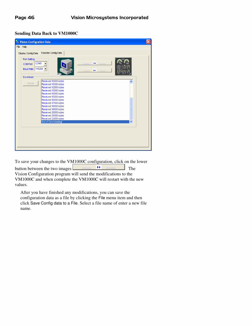
Sending Data Back to VM1000C
To save your changes to the VM1000C configuration, click on the lower
button between the two images The
Vision Configuration program will send the modifications to the
VM1000C and when complete the VM1000C will restart with the new
values.
After you have finished any modifications, you can save the
configuration data as a file by clicking the File menu item and then
click Save Config data to a File. Select a file name of enter a new file
name.

VM1000C Pilot’s Guide Page
47
Command Line Format
When the programs detects the parameters defined on the command
line, it will read the command line, transfer configuration data and
save them in the specified file automatically. There are total four
parameters on the command line:
1. /FILE: the full path of the configuration file.
2. /AUTO: the transfer mode.
3. /PORT: COM port name.
4. /BAUD: the baud rate.
The format of the parameters is as the following:
/file=c:\VISIONCONFIG\test.cfg
/auto=download (or upload)
/port=com1
/rate=19200
They are non case sensitive.
Built-in VM1000C Setup
Setup the VM1000C by performing various steps in the Setup Menu
or use Vision Config. All steps within the Mandatory Setup section
must be accomplished first. Next, verify your actual engine limits
agree with the instrument limits by stepping through all of the
ENGINE MENU limits. Adjust any displayed graphics/values/limits
to match the requirements for your engine/airframe. Finally perform
any optional setup, such as fuel level calibration, dimming
adjustment, amps zero, manifold calibration, datalog interval, RS232
setup for GPS, data log, VMFPS data ports, EC100 checklist
download.
IMPORTANT: Test your datalog port connections using a
communications program such as Teraterm or Hyperterm.
During setup, the MAN field displays the current menu item. Accept
it (by pressing �). In many cases, the RPM field shows an associated
value, except ENGINE MENU where gauge range marks and the
associated limit values are shown.

Page 48 Vision Microsystems Incorporated
To operate the Setup Menu
A. After power has been off for a minimum of 2 minutes, power
back up and hold � until you see the first menu code
displayed: 10.0.
B. Tap � or � to select to the desired menu code (example:
40.0). Tap � to change values in this category (or � to
quit).
C. Tap � or � to select the desired sub-code item, (example:
40.8). Tap � to accept this item (or � to quit).
D. Tap � or � to select the desired value or option and � to
accept it. In some cases, pressing � will exit the option
without changes.
Mandatory Setup
Code Sub-code
Category Values
I0.0 ENGINE
CONFIGURATION
I0. I I0. I I0. I I0. I Engine Code 1 = Lycoming O360
2 = Lycoming IO360
3 = Lycoming O540
4 = Lycoming IO540
5 = Continental IO360
6 = Continental IO550
20.0 CLOCK
20. I20. I20. I20. I Month 1 .. 12
20.220.220.220.2 Day 1 .. 31
20.320.320.320.3 Year 2004 .. 2199
20.420.420.420.4 Hour 0 .. 23
20.520.520.520.5 Minutes 00 .. 59
20.620.620.620.6 Seconds 00 .. 59
30.0 ENGINE HOURS
30. I30. I30. I30. I engine hours

VM1000C Pilot’s Guide Page
49
40.0 MISCELLANEOUS
40. I40. I40. I40. I Lycoming or Cont
CHT numbering.
1 = Lycoming cylinder
number front (2,1), middle
(4,3), rear (6,5).
2 = Continental cylinder
number front (6,5), middle
(4,3), rear (2,1)
40.240.240.240.2 Magneto or Electronic
Ignition.
1 = Magneto Ignition
2 = Electronic Ignition
40.340.340.340.3 Fuel Pressure Type 1 = CRB
2 = Injected.
3 = Kavlico
4 = UMA
5 = Invensys (Ratiometric)
40.440.440.440.4 Fuel units. 1 = US gallons
2 = liters
3 = UK gallon
40.540.540.540.5 Fuel level type 0 = none
1 = floats
2 = capacitance
40.640.640.640.6 Flow sensor K factor
(embossed on
transducer)
1000 .. 8700
40.740.740.740.7 Max fuel total limit 1 .. 400
40.840.840.840.8 Low fuel total alarm 0 .. 400
40.940.940.940.9 Temperature units. 1 = F °
2 = C °
4 I.04 I.04 I.04 I.0 Lean method 1 = rich of peak
2 = lean of peak
4 I. I4 I. I4 I. I4 I. I Datalog interval in
seconds
6 .. 720
4 I.24 I.24 I.24 I.2 Alarm volume level 0 .. 100
4 I.34 I.34 I.34 I.3 Auto Snapshot Mode 0 = off
1 = on

Page 50 Vision Microsystems Incorporated
4 I.44 I.44 I.44 I.4 MAN transducer 1 = Standard
2 = Kavlico
3=UMA
4 I.54 I.54 I.54 I.5 FADEC option. 0 = no fadec
1 = fadec
4 I.64 I.64 I.64 I.6 Number of TIT probes 0 = none
1= one TIT
2 = two TITs
4 I.74 I.74 I.74 I.7 Engine rated HP from
that set in engine setup
85 .. 900
4 I.84 I.84 I.84 I.8 User Shock Cooling
rate alarm
15 .. 120 °/min
4 I.94 I.94 I.94 I.9 Oil Pressure Type 1 = VDO
only
42.042.042.042.0 OAT Units 1 = F °
2 = C °
End of initial mandatory setup
User Setup
45.045.045.045.0 Backlight low level. 2 .. 150
45. I45. I45. I45. I GAMI HP constant 0 .. 16.0 (only change this if
you have GAMI injectors
and are knowledgeable on
them)
45.245.245.245.2 Amps Sensor Type Always 100 Amps
45.345.345.345.3 Manifold Pressure
correction
Manifold adjustment +/- 3.0
inches of Hg.
45.445.445.445.4 (function reserved)
45.545.545.545.5 Software revision
number
Read-only. Cannot be
changed
45.645.645.645.6 Aircraft Id# 0000-9999
45.745.745.745.7 EC100 status 0 = not present
1= present
2=EC150 with voice

VM1000C Pilot’s Guide Page
51
50.050.050.050.0 User definable engine
parameters
* If chosen in “range marks
desired” section
50. I50. I50. I50. I Percent power • range marks desired
• low green
• high green
• high red (if chosen*)
• Autotrack tolerance
• Alarm tolerance
50.250.250.250.2 Manifold pressure • range marks desired
• low green
• high green
• high red (if chosen*)
• Autotrack tolerance
• Alarm tolerance
50.350.350.350.3 RPM • range marks desired
• low green
• high green
• high red
• Autotrack tolerance
• Alarm tolerance
50.450.450.450.4 Oil pressure • Idle low red (idL)
• low red (nor)
• low green
• high green
• high red
• Autotrack tolerance
• Alarm tolerance
50.550.550.550.5 Oil temperature • range marks desired
• low red (if chosen*)
• low green
• high green
• high red
• Autotrack tolerance
• Alarm tolerance

Page 52 Vision Microsystems Incorporated
50.650.650.650.6 Volts • low red
• low green
• high green
• high red
• Autotrack tolerance
• Alarm tolerance
50.750.750.750.7 Amps • range marks desired
• low red (if chosen*)
• low green
• high green
• high red (if chosen*)
• Autotrack tolerance
• Alarm tolerance
50.850.850.850.8 Fuel computer • range marks desired
• low red (if chosen*)
• low green
• high green
• high red (if chosen*)
• Autotrack tolerance
• Alarm tolerance
50.950.950.950.9 Fuel pressure • range marks desired
• low red (if chosen*)
• low green
• high green
• high red (if chosen*)
• Autotrack tolerance
• Alarm tolerance
5 I.05 I.05 I.05 I.0 CHT • 6 or 4 cylinder engine
• low green
• high green
• high red
• Autotrack tolerance
• Alarm tolerance

VM1000C Pilot’s Guide Page
53
5 5 5 5 I. II. II. II. I EGT • bottom segment
• top segment
• Autotrack tolerance
• Alarm tolerance
5 I.25 I.25 I.25 I.2 TIT • low green
• high green
• high red (tithi)
• low red (titln)
• Autotrack tolerance
• Alarm tolerance
60.060.060.060.0 Fuel Level
Calibration
60. I60. I60. I60. I • range marks desired
Perform the following steps for each tank you are using:
1. Add desired unit of fuel (we recommend 2 gallon
increments) (do a 0 cal first)
2. Hold ���� or ���� to set the current total of fuel in tank.
(displayed on fuel indicator)
3. Calibration number will change as fuel level change (RPM
display)
4. Tap ���� to accept this data point. (value will increment to
next minimum allowed)
5. Repeat 1 thru 4 until the tank is full and final data point
accepted then tap ���� next
If a Calibration has already been done, it must be erased before
performing the calibration again. See page 49
60.260.260.260.2 PRIMARY left fuel
tank cal
60.360.360.360.3 PRIMARY Right fuel
tank cal

Page 54 Vision Microsystems Incorporated
60.460.460.460.4 PRIMARY left tank
alarm (cant set the
alarms unless a cal
has been done)
60.560.560.560.5 PRIMARY right tank
alarm
60.660.660.660.6 SECONDARY
(GROUND) left tank
cal
60.760.760.760.7 SECONDARY
(GROUND) right
tank cal.
60.860.860.860.8 SECONDARY
(GROUND) left tank
alarm
60.960.960.960.9 SECONDARY
(GROUND) right
tank alarm
6 I.06 I.06 I.06 I.0 Erase PRIMARY left
tank cal (������������
held down to erase)
����
will exit
6 I. I6 I. I6 I. I6 I. I Erase PRIMARY
Right tank cal
6 I.26 I.26 I.26 I.2 Erase SECONDARY
(GROUND) left tank
cal
6 I.36 I.36 I.36 I.3 Erase SECONDARY
(GROUND) right
tank cal
70.0 RS232 Setup
70. I70. I70. I70. I Port A (TTY0) baud
rate
9600, 19200, 38400, 57600
70.270.270.270.2 Port B (TTY1) baud
rate
4800, 9600, 19200, 38400,
57600

VM1000C Pilot’s Guide Page
55
70.370.370.370.3 Port B (TTY1) output
mode
0 = none
1 = Shadin generic
2 = Shadin Mode S
70.470.470.470.4 Download Data 1 = files since last download
2 = all files
70.570.570.570.5 Send test message to
both ports.
70.670.670.670.6 EC100 upload
1 = upload EC100 checklist
from PC (use Teraterm to
send)
2 = download the EC100
that is currently in
VM1000C (use log option in
Teraterm)
70.770.770.770.7 Download System
Configuration to PC
70.870.870.870.8 Upload system
configuration from
PC
70.9 70.9 70.9 70.9 Erase All Flights. Hold ���
simultaneously to erase, �
to exit mode. The WARN
enunciator will flash until
you either tap � to escape
or ���. WARN will
remain on until erasure is
complete.
Percent Power Operation / Calibration
Calibration steps on the ground
STEP 1: Set MISCELLANEOUS: LEANING MODE to Rich of
Peak.

Page 56 Vision Microsystems Incorporated
STEP 2: Set MISCELLANEOUS: ENGINE HORSEPOWER to
your engines rated horsepower.
STEP 3: If you have a GAMI Horsepower Constant calculated,
then enter it in MISCELLANEOUS: GAMI
HORSEPOWER CONSTANT.
STEP 4: Using your engine operation manual, determine the
RPM, MAN and desired Altitude to obtain 75% power.
Write these three down for reference later.
Calibration steps in the air
STEP 5: Setup the 75% power RPM & MAN and altitude from
STEP 4. Correct this percentage for the outside air
temperature and note it.
STEP 6: Perform a leaning operation to 50° Rich of Peak.
STEP 7: Enter the %HP calibrate mode by holding � and �
until the MAN and %HP icons alternately flash.
STEP 8: Tap � or � to adjust % HP to the corrected %HP
noted from STEP 5.
STEP 9: Tap � to save the calibration or � to cancel the
mode.
Fuel Level System Calibration
The VM1000C supports either single or dual fuel tank monitoring.
Each monitored tank must have a PRIMARY CALIBRATION
performed. For aircraft having a significantly different calibration
reading in cruise vs. on the ground, such as taildraggers, you may
optionally perform a SECONDARY CALIBRATION. The
VM1000C will then automatically switch between PRIMARY
(airborne) and SECONDARY (ground) calibrations as needed. See
FUEL LEVEL CALIBRATION for the commands on fuel level
calibration. Note: Any previous tank calibration must be erased
before performing the new calibration.

VM1000C Pilot’s Guide Page
57
First, prepare the tank for calibration by draining it to UNUSABLE
fuel and positioning the aircraft in the desired calibration attitude -
cruise attitude for the PRIMARY (required) or ground attitude
(optional) for SECONDARY.
These are the basic steps for each tank calibration
STEP 1. With UNUSABLE fuel in the tank and fuel level
indicator showing zero quantity, Tap � to save this data
point.
STEP 2. Add desired increment of fuel (we recommend 2 gallon
(8 liter) increments).
STEP 3. Tap � or � to set the fuel level quantity indicator to
agree with the usable fuel in the tank.
STEP 4. Tap � to accept this calibration data point. The fuel
sensor signal output is shown in the RPM field (note that
it changes when fuel is added). Write the value down and
the current fuel quantity. Repeat from STEP 2 until your
tank is full.
STEP 5: Tap � to exit the fuel tank calibration.

Page 58 Vision Microsystems Incorporated
Section 5 - CONNECTOR PIN ASSIGNMENTS
P1 Options 25-pin
connector
P3 MAN-RPM 9-pin
connector
P4 Fuel Flow 15-pin
connector
Pin
no.
Pin
no.
Probe or
function
Pin
no.
Function/
sensor pin
Pin
no.
Function
yel 1 red 2 OIL grn 1 RPM sig /1 1 out to GPS yel 3 red 4 IND blk 2 RPM grd /2 2 in from GPS yel 5 red 6 CARB* red 3 RPM pwr /3 3
yel 14 red 15 OAT red 4 MAN pwr /3 wht 4 FF signal yel 16 red 17 TIT-1 blk 5 MAN grd /1 red 5 FF power yel 18 red 19 TIT-2 6 OIL P sig blk 6 FF ground
7 OIL P grd gry 12 Remote alert T,V
wht 8 MAN sig+ /2
10 R Fuel Low Switch
red 13 + Power grn 9 MAN sig- /4 11 remote FF alarm
wht 12 FF2 signal wht 11 wht 24
data in data out
13 L Fuel Low
Switch 14 AMPS 2 + blk 25 Engine
ground
15 AMPS 2 -
*Displays as CRB if IAT probe is not present; displays as CDT is IAT if present.
P2 EGT CHT 25-pin
connector
P5 FP/FQ/AMP 15-pin
connector
Pin
no.
Pin
no.
Probe or
function
Pin
no.
Function
yel 1 red 2 CHT 1 1 FQ 1 (res)
yel 3 red 4 CHT 2 2 FQ 2 (res)
yel 5 red 6 CHT 3 3 FQ grd
yel 7 red 8 CHT 4 4 FP Sig+
yel 9 red 10 CHT 5 5 FP Sig-
yel 11 red 12 CHT 6 6 FP pwr
yel 14 red 15 EGT 1 7 FP grd
yel 16 red 17 EGT 2 8
yel 18 red 19 EGT 3 9 FQ1 sig (cap)
yel 20 red 21 EGT 4 10 FQ2 sig (cap)
yel 22 red 23 EGT 5 11 FQ1 pwr (cap)
yel 24 red 25 EGT 6 12 FQ2 pwr (cap)
13 Volts 2 sense 14 AMPS +
15 AMPS -

VM1000C Pilot’s Guide Page
59
Section 6 - TECHNICAL SUPPORT
Website: http://www.visionmicrosystems.com/
Email support: [email protected]

Page 60 Vision Microsystems Incorporated
Index
A
Adding fuel, 7
Air temperature
operation, 13
Alarm volume, 41
Ammeter shunt
installation, 29
Amperes, 10
Amps sensor type, 42
Autotrack
operation, 10
B
Backlight, 42
Baud rate, 46
Brightness, 42
Buttons, 1
C
Cable harness, 20
Calibration
fuel level, 45, 48
Capactive
fuel sender installation, 30
Carburetor probe
installation, 27
Carburetor temperature
operation, 13
CDT probe
installation, 26
Checklist, 15
CHT probe
installation, 25
Clock, 40
Code
engine, 40
Codes
setup, 39
Configuration, 39
Connector
pin assignments, 50
Cylinder numbering, 41
Cylinder Watch, 7
D
Data recorder
operation, 12
Datalog interval, 41
DIF, 9
Dimming, 2
Display
brightness, 2
Download data, 13
E
EC100
operation, 15
ECAS, 16
EGT analyzer
operation, 8
EGT probe
installation, 24
Electrical monitoring
Operation, 10
Electronic ignition, 41
email, 51
Engine code, 40
Engine hours, 41
Engine parameters, 43
Enging operating hours, 2
Erase memory, 47
EZTrends, 12
F
FADEC option, 42
Flight data recorder
operation, 12

VM1000C Pilot’s Guide Page
61
Fuel
adding, 7
Fuel computer
operation, 5
Fuel flow transducer installation, 34
Fuel level
calibration, 48
operation, 14
Fuel level calibration, 45
Fuel level sender
fu installation, 30
Fuel level type, 41
Fuel pressure sensor
installation, 29
Fuel pressure type, 41
Fuel total, 41
Fuel units, 41
G
GAMI constant, 42
H
Horsepower, 4
calibration, 47
Horsepower setup, 42
I
IAT probe
installation, 26
Ignition type, 41
Induction air probe
installation, 26
Initial configuration, 39
Installation, 18
K
K-factor, 34, 41
L
Lean method, 41
Level
fuel, 14
Low fuel, 41
Low level brightness, 42
M
Magneto, 41
MAN, 3
MAN transducer type, 42
Manifold pressure
calibration, 3
operation, 3
Memory
erase, 47
Mounting template, 18
O
OAT probe
installation, 26
OAT units, 42
Oil pressure
operation, 4
Oil pressure sensor
installation, 28
Oil pressure type, 42
Oil temperature
operation, 5
Operating hours
engine, 2
Outside air temperature
operation, 13
Outside air temperature probe
installation, 26
P
Peaking mode
operation, 9
Percent power
calibration, 4, 47

Page 62 Vision Microsystems Incorporated
operation, 4
Pin assignments
connectors, 50
Probe list, 22
Product support, 51
R
Recorder
operation, 12
Resistive fuel sender
installation, 33
RPM operation, 2
RPM sensor
installation, 29
S
Serial data com setup, 46
Setup, 39
engine parameters, 43
Setup codes, 39
Shock cooling setup, 42
Snapshot, 12, 42
Support
technical, 51
System setup, 39
T
Tachometer operation, 2
Tachometer sensor
installation, 29
Technical support, 51
Temperature units, 41, 42
Template
mounting, 18
Time
set, 40
TIT
operation, 14
TIT probe
installation, 25
TIT probes, 42
Transducer list, 22
Turbo inlet temperature
operation, 14
V
VisionConfig, 36
Volts
Operation, 10
Volume
alarm, 41
W
Website, 51
Wiring harness, 20