pilot’s operating handbook - · pdf filepilot’s operating handbook rv-3 b page 1...
TRANSCRIPT

Pilot’s Operating Handbook
RV-3B
Rev. 10/06/2010 Copyright © M. Kletzenbauer

To-do: • Collect final fuel consumption data for 55%/65%/75%
power @ 8,000’, 50 degrees LOP, enter in tables • Extrapolate range data, enter in tables • Collect rate of climb data, enter in table • Finish power table, replace rule-of-48 table? • ?

Table of contents
General Information........................................................1 Specifications ..................................................................2 Performance....................................................................3
Operating Speeds – MPH ..................................................... 4 Operating Speeds – KNOTS ................................................. 4 Aerobatic information .......................................................... 5 Fuel consumption & range ................................................... 6
Weight & Balance............................................................7 W&B Worksheet................................................................... 8 Sample scenarios ................................................................. 8
Procedures....................................................................10 Normal Procedures.........................................................10 EMERGENCY PROCEDURES...........................................13
Systems & Descriptions.................................................15 Engine Operation ...........................................................15 Power Chart....................................................................16 Engine Start Procedures .................................................17 Mixture management......................................................18 Fuel system.....................................................................18 Electrical system.............................................................20 Personal Locator Beacon.................................................21
Quick Reference Operating Instructions.......................22 Maintenance..................................................................23
Engine Information .........................................................23 Maintenance schedule ....................................................24 Propeller maintenance....................................................32
Supplements .................................................................33 List of manuals ................................................................33 Conversion Reference ....................................................33 General info....................................................................33
Computing descent point DISTANCE:................................ 33 Computing descent point RATE: ........................................ 33

Pilot’s Operating Handbook RV-3 B
Page 1
General Information
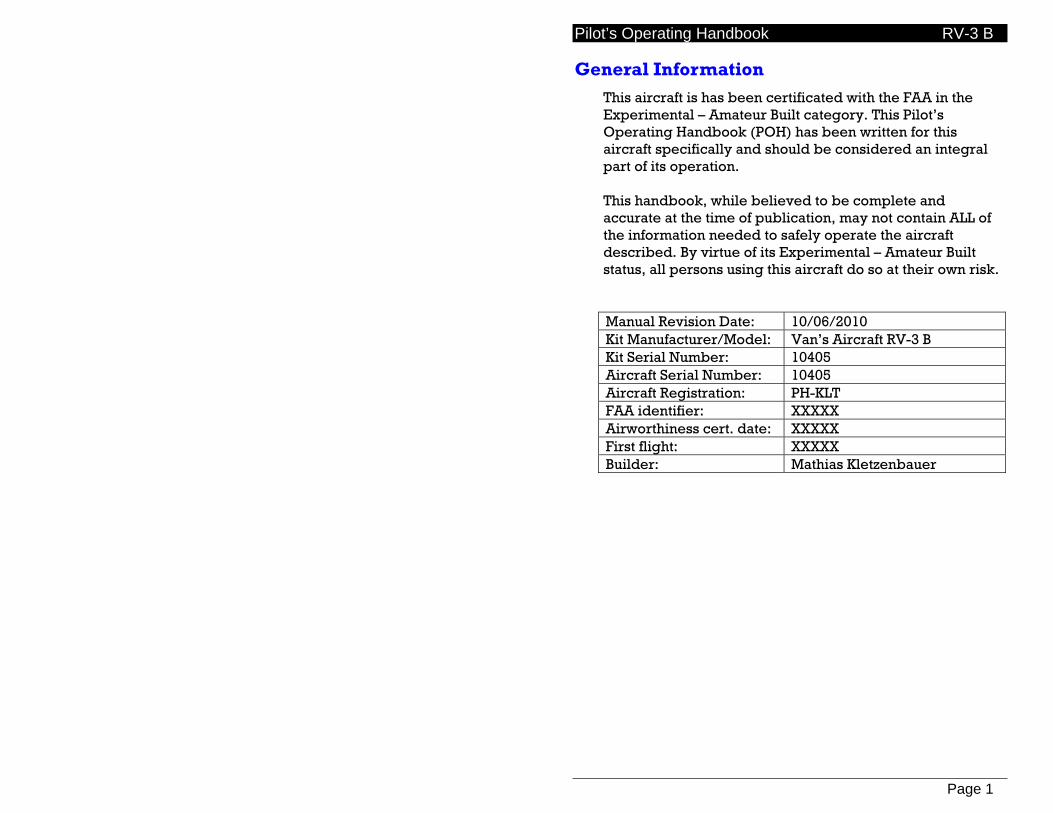
This aircraft is has been certificated with the FAA in the Experimental – Amateur Built category. This Pilot’s Operating Handbook (POH) has been written for this aircraft specifically and should be considered an integral part of its operation. This handbook, while believed to be complete and accurate at the time of publication, may not contain ALL of the information needed to safely operate the aircraft described. By virtue of its Experimental – Amateur Built status, all persons using this aircraft do so at their own risk.
Manual Revision Date: 10/06/2010 Kit Manufacturer/Model: Van’s Aircraft RV-3 B Kit Serial Number: 10405 Aircraft Serial Number: 10405 Aircraft Registration: PH-KLT FAA identifier: XXXXX Airworthiness cert. date: XXXXX First flight: XXXXX Builder: Mathias Kletzenbauer
Pilot’s Operating Handbook RV-3 B
Page 2
Specifications
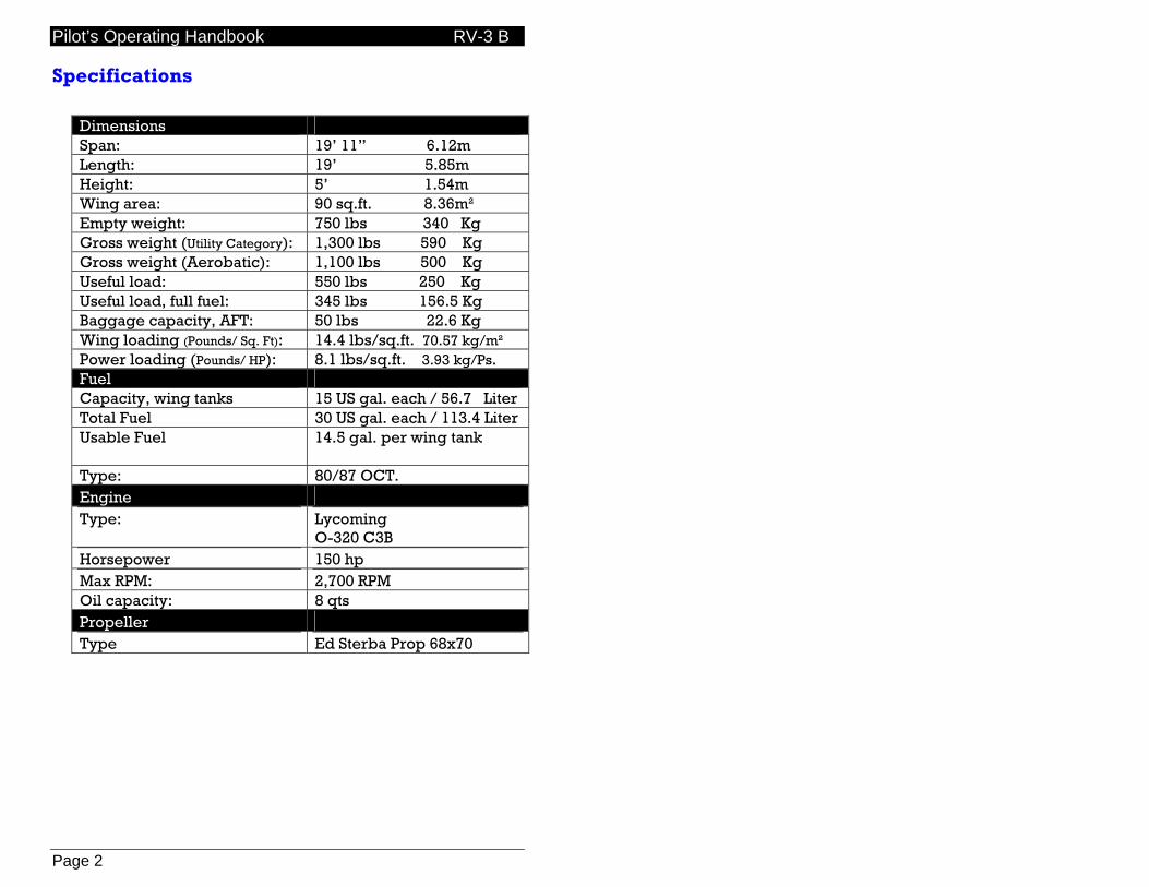
Dimensions Span: 19’ 11” 6.12m Length: 19’ 5.85m Height: 5’ 1.54m Wing area: 90 sq.ft. 8.36m² Empty weight: 750 lbs 340 Kg Gross weight (Utility Category): 1,300 lbs 590 Kg Gross weight (Aerobatic): 1,100 lbs 500 Kg Useful load: 550 lbs 250 Kg Useful load, full fuel: 345 lbs 156.5 Kg Baggage capacity, AFT: 50 lbs 22.6 Kg Wing loading (Pounds/ Sq. Ft): 14.4 lbs/sq.ft. 70.57 kg/m² Power loading (Pounds/ HP): 8.1 lbs/sq.ft. 3.93 kg/Ps. Fuel Capacity, wing tanks 15 US gal. each / 56.7 Liter Total Fuel 30 US gal. each / 113.4 Liter Usable Fuel 14.5 gal. per wing tank
Type: 80/87 OCT. Engine Type: Lycoming
O-320 C3B Horsepower 150 hp Max RPM: 2,700 RPM Oil capacity: 8 qts Propeller Type Ed Sterba Prop 68x70

Pilot’s Operating Handbook RV-3 B
Page 3
Performance
Speed (TAS) Maximum at Sea Level 220 mph (190) kts Cruise, 75% Power at 8,000 Ft 213 mph (185 kts) Cruise, 55% Power at 8,000 Ft 182 mph (158 kts) Gross weight:
Stall speed (Vso) 60 mph (52 kts) Stall speed (clean) 64 mph (55 kts)
Solo/light: Stall speed (Vso) 58 mph (50 kts) Stall speed (clean) 62 mph (53 kts)
Range @ 8,000’, 30 min. reserve 75% power 595 sm (520 nm) 65% power 655 sm (569 nm) 55% power 715 sm (621 nm) Rate of climb at sea level Gross weight 2,500 fpm Service ceiling Gross weight: 23,500 ft Takeoff distance (sea level) Gross weight: 400 ft Landing distance (sea level) Gross weight: 400 ft
Pilot’s Operating Handbook RV-3 B
Page 4
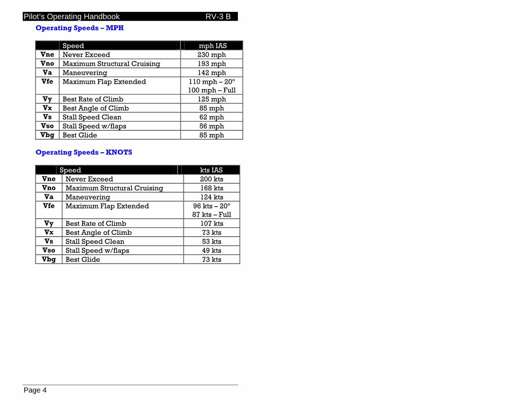
Operating Speeds – MPH
Speed mph IAS Vne Never Exceed 230 mph Vno Maximum Structural Cruising 193 mph Va Maneuvering 142 mph Vfe Maximum Flap Extended 110 mph – 20º
100 mph – Full Vy Best Rate of Climb 125 mph Vx Best Angle of Climb 85 mph Vs Stall Speed Clean 62 mph
Vso Stall Speed w/flaps 56 mph Vbg Best Glide 85 mph
Operating Speeds – KNOTS
Speed kts IAS Vne Never Exceed 200 kts Vno Maximum Structural Cruising 168 kts Va Maneuvering 124 kts Vfe Maximum Flap Extended 96 kts – 20º
87 kts – Full Vy Best Rate of Climb 107 kts Vx Best Angle of Climb 73 kts Vs Stall Speed Clean 53 kts
Vso Stall Speed w/flaps 49 kts Vbg Best Glide 73 kts
Pilot’s Operating Handbook RV-3 B
Page 5
Aerobatic information
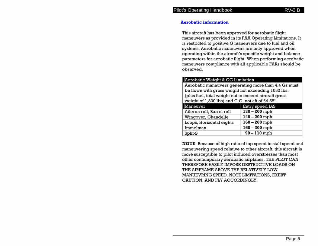
This aircraft has been approved for aerobatic flight maneuvers as provided in its FAA Operating Limitations. It is restricted to positive G maneuvers due to fuel and oil systems. Aerobatic maneuvers are only approved when operating within the aircraft’s specific weight and balance parameters for aerobatic flight. When performing aerobatic maneuvers compliance with all applicable FARs should be observed.
Aerobatic Weight & CG Limitation Aerobatic maneuvers generating more than 4.4 Gs must be flown with gross weight not exceeding 1050 lbs. (plus fuel, total weight not to exceed aircraft gross weight of 1,300 lbs) and C.G. not aft of 64.58”. Maneuver Entry speed IAS Aileron roll, Barrel roll 130 – 200 mph Wingover, Chandelle 140 – 200 mph Loops, Horizontal eights 160 – 200 mph Immelman 160 – 200 mph Split-S 90 – 110 mph
NOTE: Because of high ratio of top speed to stall speed and maneuvering speed relative to other aircraft, this aircraft is more susceptible to pilot induced overstresses than most other contemporary aerobatic airplanes. THE PILOT CAN THEREFORE EASILY IMPOSE DESTRUCTIVE LOADS ON THE AIRFRAME ABOVE THE RELATIVELY LOW MANUEVRING SPEED. NOTE LIMITATIONS, EXERT CAUTION, AND FLY ACCORDINGLY.

Pilot’s Operating Handbook RV-3 B
Page 6
Fuel consumption & range Fuel consumption can be minimized and efficiency improved via leaning techniques and reduced power settings.
--- 8000’ MSL --- Power MAPxRPM Mixture Burn Speed 75% 24x2400 75° LOP 7.8 gph 202 mph TAS 65% 22.5x2250 75° LOP 6.6 gph 193 mph TAS 55% 20.5x2050 75° LOP 5.2 gph 175 mph TAS

Pilot’s Operating Handbook RV-3 B
Page 7
Weight & Balance
This aircraft’s documentation includes a separate Weight & Balance Data sheet that must be kept in the aircraft at all times and is part of the documentation upon which its Airworthiness Certificate is conditioned. Information presented below should always be superceded by the FAA-approved Weight & Balance Data sheet onboard the aircraft. Weights & Limits Summary Empty weight: 750 lbs Gross weight (Normal Category): 1,300 lbs Gross weight (Aerobatic Category): 1,100 lbs Maximum useful load: 550 lbs Maximum useful load with full fuel: 374 lbs Baggage capacity (aft): 50 lbs Forward CG limit: 59.72" aft of datum Aft CG limit: 64.58" aft of datum Aerobatic aft CG limit: 64.58" aft of datum

Pilot’s Operating Handbook RV-3 B
Page 8
W&B Worksheet Aircraft empty weight includes .5 gallons unusable fuel and 8 qts. oil. The following table may be used to compute W&B data for each flight.
Weight Arm Moment Empty aircraft: 741,2 55,74 41314,48 Fuel (29.4 gal.): 58.5 Pilot: 81.0 Aft baggage shelf: 112.5 Total: CG:
Sample scenarios LIGHT - TAKEOFF (most fwd C.G.) Weight Arm Moment Empty aircraft: 741.2 55,74 41,314.48 Fuel (29.4 gal.): 176.4 58.50 10,319.40 Pilot: 220.0 81.00 17,820.00 Aft baggage: 0.0 112.50 0 Total: 1,137.6 69,453.88 CG: 61.05 LIGHT - LANDING Weight Arm Moment Empty aircraft: 741.2 55.74 41,314.48 Fuel (5 gal.): 30.0 58.50 1,755.00 Pilot: 220.0 81.00 17.820.00 Aft baggage: 0.0 112.50 0 Total: 991.0 60.889,48 CG: 61.43 GROSS WEIGHT - TAKEOFF Weight Arm Moment Empty aircraft: 741.2 55.74 41.314,48 Fuel (29.4 gal.): 176.4 58.50 10,319.40 Pilot: 220.0 81.00 17.820.00 Aft baggage: 60.0 112.50 6,750.00 Total: 1.197,6 76.203,88 CG: 63.63

Pilot’s Operating Handbook RV-3 B
Page 9
GROSS WEIGHT - LANDING (most aft C.G.) Weight Arm Moment Empty aircraft: 741,2 55.74 41.314,48 Fuel (5 gal.): 30.0 58.50 1.755,00 Pilot: 220.0 81.00 17.820,00 Aft baggage: 60.0 112.50 6,750.00 Total: 1.051,0 67.639,48 CG: 64.35 Smoke oil CG Weight Arm Moment Empty aircraft: 741,2 55.74 41.314,48 Fuel (29.4 gal.): 176.4 58.50 10,319,40 Pilot: 220.0 81.00 17.820,00 Aft baggage: 0.0 112.50 0.00 Smoke tank: 11.0 112.50 1,237,50 Smoke fuel: 30.0 112.50 3.375,00 Total: 1.181,6 74.066,38 CG: 62,68 AEROBATIC WEIGHT & C.G. LIMITS Aerobatic maneuvers generating more than +4.4 Gs must be flown with gross weight not exceeding 1100 lbs. (plus fuel, total weight not to exceed aircraft gross weight of 1,300 lbs) and C.G. not aft of 64.58”.
Pilot’s Operating Handbook RV-3 B
Page 10
Procedures
Normal Procedures
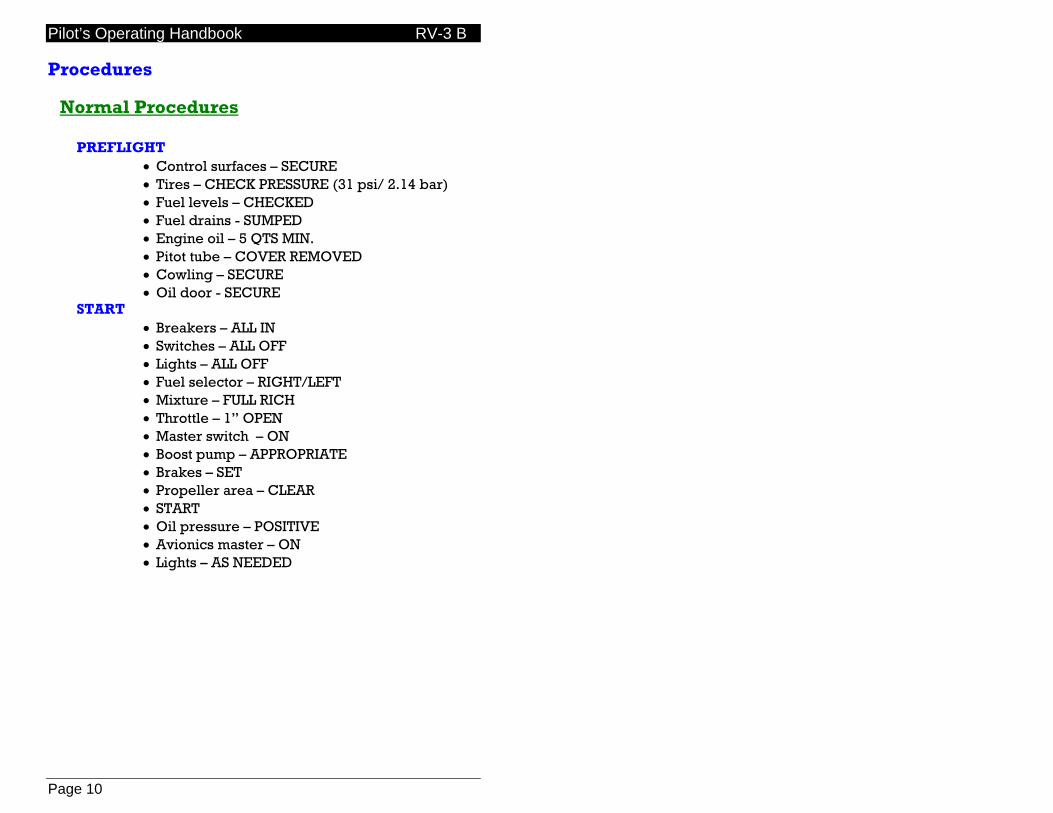
PREFLIGHT • Control surfaces – SECURE • Tires – CHECK PRESSURE (31 psi/ 2.14 bar) • Fuel levels – CHECKED • Fuel drains - SUMPED • Engine oil – 5 QTS MIN. • Pitot tube – COVER REMOVED • Cowling – SECURE • Oil door - SECURE
START • Breakers – ALL IN • Switches – ALL OFF • Lights – ALL OFF • Fuel selector – RIGHT/LEFT • Mixture – FULL RICH • Throttle – 1” OPEN • Master switch – ON • Boost pump – APPROPRIATE • Brakes – SET • Propeller area – CLEAR • START • Oil pressure – POSITIVE • Avionics master – ON • Lights – AS NEEDED
Pilot’s Operating Handbook RV-3 B
Page 11
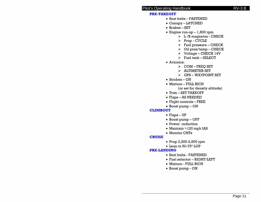
PRE-TAKEOFF • Seat belts – FASTENED • Canopy – LATCHED • Brakes – SET • Engine run-up – 1,800 rpm
L /R magnetos - CHECK Prop - CYCLE Fuel pressure – CHECK Oil pres/temp – CHECK Voltage – CHECK 14V Fuel tank – SELECT
• Avionics: COM – FREQ SET ALTIMETER SET GPS – WAYPOINT SET
• Strobes – ON • Mixture – FULL RICH (or set for density altitude) • Trim – SET TAKEOFF • Flaps – AS NEEDED • Flight controls – FREE • Boost pump – ON
CLIMBOUT • Flaps – UP • Boost pump – OFF • Power reduction • Maintain >120 mph IAS • Monitor CHTs
CRUISE • Prop 2,200-2,600 rpm • Lean to 50-75° LOP
PRE-LANDING • Seat belts - FASTENED • Fuel selector – RIGHT/LEFT • Mixture - FULL RICH • Boost pump - ON
Pilot’s Operating Handbook RV-3 B
Page 12
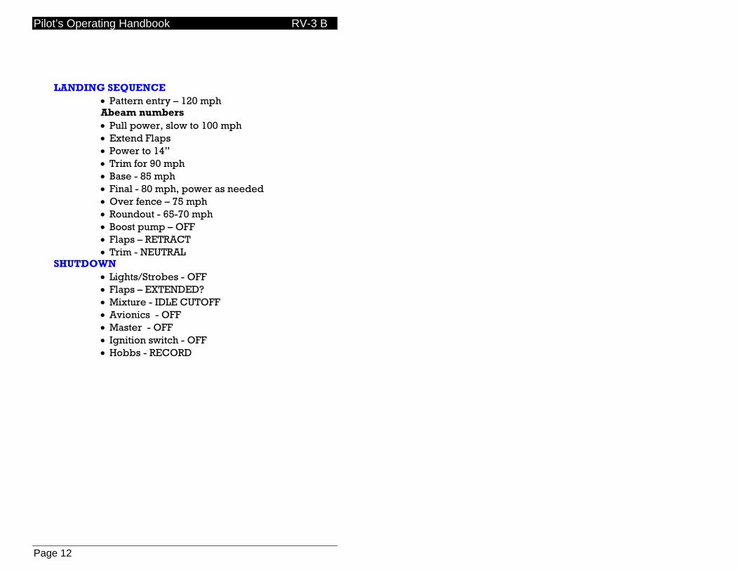
LANDING SEQUENCE
• Pattern entry – 120 mph Abeam numbers • Pull power, slow to 100 mph • Extend Flaps • Power to 14” • Trim for 90 mph • Base - 85 mph • Final - 80 mph, power as needed • Over fence – 75 mph • Roundout - 65-70 mph • Boost pump – OFF • Flaps – RETRACT • Trim - NEUTRAL
SHUTDOWN • Lights/Strobes - OFF • Flaps – EXTENDED? • Mixture - IDLE CUTOFF • Avionics - OFF • Master - OFF • Ignition switch - OFF • Hobbs - RECORD
Pilot’s Operating Handbook RV-3 B
Page 13
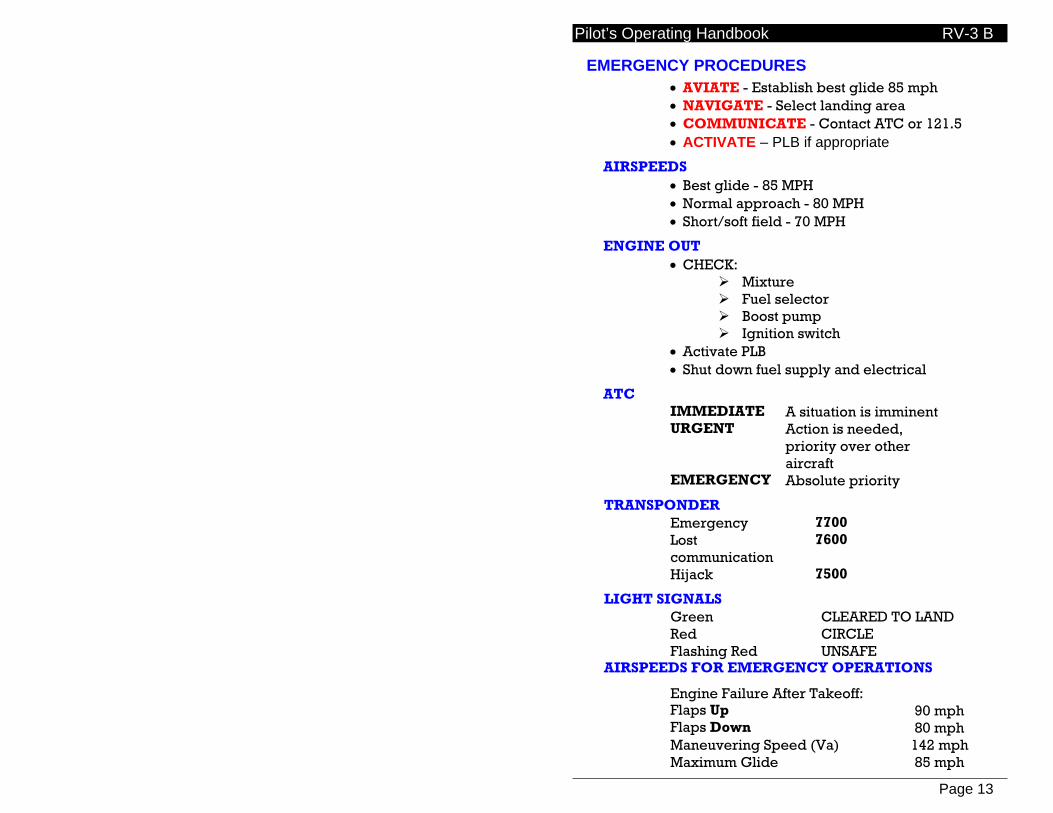
EMERGENCY PROCEDURES • AVIATE - Establish best glide 85 mph • NAVIGATE - Select landing area • COMMUNICATE - Contact ATC or 121.5 • ACTIVATE – PLB if appropriate
AIRSPEEDS • Best glide - 85 MPH • Normal approach - 80 MPH • Short/soft field - 70 MPH
ENGINE OUT • CHECK:
Mixture Fuel selector Boost pump Ignition switch
• Activate PLB • Shut down fuel supply and electrical
ATC IMMEDIATE A situation is imminent URGENT Action is needed,
priority over other aircraft
EMERGENCY Absolute priority
TRANSPONDER Emergency 7700 Lost communication
7600
Hijack 7500
LIGHT SIGNALS Green CLEARED TO LAND Red CIRCLE Flashing Red UNSAFE
AIRSPEEDS FOR EMERGENCY OPERATIONS
Engine Failure After Takeoff: Flaps Up Flaps Down
90 mph 80 mph
Maneuvering Speed (Va) 142 mph Maximum Glide 85 mph

Pilot’s Operating Handbook RV-3 B
Page 14

Pilot’s Operating Handbook RV-3 B
Page 15
Systems & Descriptions
Engine Operation For full information on engine operation, maintenance, and troubleshooting see “Operators Manual, Lycoming Aircraft Engines, O-320 Series”,
Oil pressure: 55-95 psi cruise
25 psi idling. Oil temperature: Maintain between 180º - 245º F. Cylinder head temperature:
Maximum temp 500º. For maximum service life maintain below 435º F during high-performance climb operation and 400º F during continuous operation.
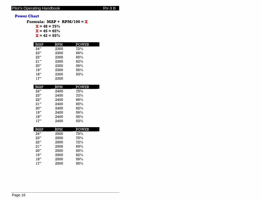
Normal Lycoming power charts based on altitude cannot be used with RV aircraft built using Van’s Filtered Airbox (FAB) due to the ram-air effect and efficiency of the intake design. Consequently the following power chart may be used to approximate percent engine power based on a combination of manifold pressure and engine speed.
Pilot’s Operating Handbook RV-3 B
Page 16
Power Chart Formula: MAP + RPM/100 = X
X = 48 = 75% X = 45 = 65% X = 42 = 55%
MAP RPM POWER 24” 2300 72% 23” 2300 69% 22” 2300 65% 21” 2300 62% 20” 2300 59% 19” 2300 55% 18” 2300 53% 17” 2300
MAP RPM POWER 24” 2400 75% 23” 2400 72% 22” 2400 69% 21” 2400 65% 20” 2400 62% 19” 2400 59% 18” 2400 55% 17” 2400 53%
MAP RPM POWER 24” 2500 79% 23” 2500 75% 22” 2500 72% 21” 2500 69% 20” 2500 65% 19” 2500 62% 18” 2500 59% 17” 2500 55%
Pilot’s Operating Handbook RV-3 B
Page 17
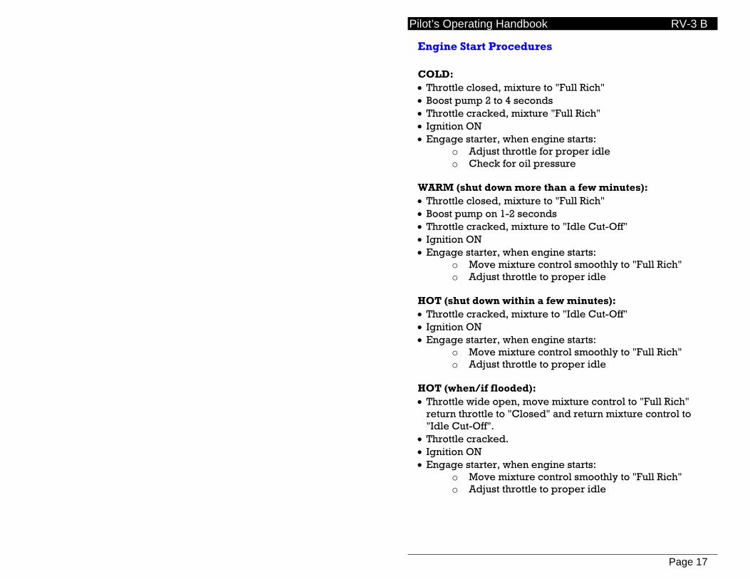
Engine Start Procedures COLD: • Throttle closed, mixture to "Full Rich" • Boost pump 2 to 4 seconds • Throttle cracked, mixture "Full Rich" • Ignition ON • Engage starter, when engine starts:
o Adjust throttle for proper idle o Check for oil pressure
WARM (shut down more than a few minutes): • Throttle closed, mixture to "Full Rich" • Boost pump on 1-2 seconds • Throttle cracked, mixture to "Idle Cut-Off" • Ignition ON • Engage starter, when engine starts:
o Move mixture control smoothly to "Full Rich" o Adjust throttle to proper idle
HOT (shut down within a few minutes): • Throttle cracked, mixture to "Idle Cut-Off" • Ignition ON • Engage starter, when engine starts:
o Move mixture control smoothly to "Full Rich" o Adjust throttle to proper idle
HOT (when/if flooded): • Throttle wide open, move mixture control to "Full Rich"
return throttle to "Closed" and return mixture control to "Idle Cut-Off".
• Throttle cracked. • Ignition ON • Engage starter, when engine starts:
o Move mixture control smoothly to "Full Rich" o Adjust throttle to proper idle
Pilot’s Operating Handbook RV-3 B
Page 18
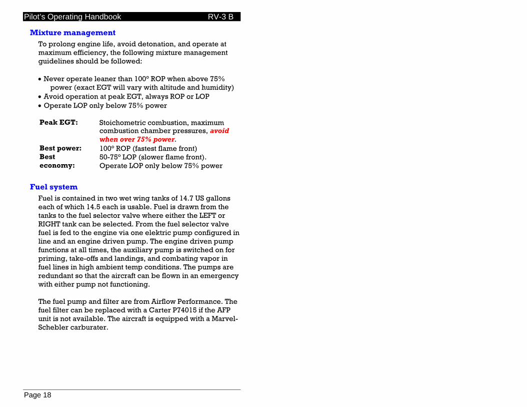
Mixture management To prolong engine life, avoid detonation, and operate at maximum efficiency, the following mixture management guidelines should be followed: • Never operate leaner than 100° ROP when above 75%
power (exact EGT will vary with altitude and humidity) • Avoid operation at peak EGT, always ROP or LOP • Operate LOP only below 75% power
Peak EGT: Stoichometric combustion, maximum
combustion chamber pressures, avoid when over 75% power.
Best power: 100° ROP (fastest flame front) Best economy:
50-75° LOP (slower flame front). Operate LOP only below 75% power
Fuel system Fuel is contained in two wet wing tanks of 14.7 US gallons each of which 14.5 each is usable. Fuel is drawn from the tanks to the fuel selector valve where either the LEFT or RIGHT tank can be selected. From the fuel selector valve fuel is fed to the engine via one elektric pump configured in line and an engine driven pump. The engine driven pump functions at all times, the auxiliary pump is switched on for priming, take-offs and landings, and combating vapor in fuel lines in high ambient temp conditions. The pumps are redundant so that the aircraft can be flown in an emergency with either pump not functioning. The fuel pump and filter are from Airflow Performance. The fuel filter can be replaced with a Carter P74015 if the AFP unit is not available. The aircraft is equipped with a Marvel-Schebler carburater.
Pilot’s Operating Handbook RV-3 B
Page 19
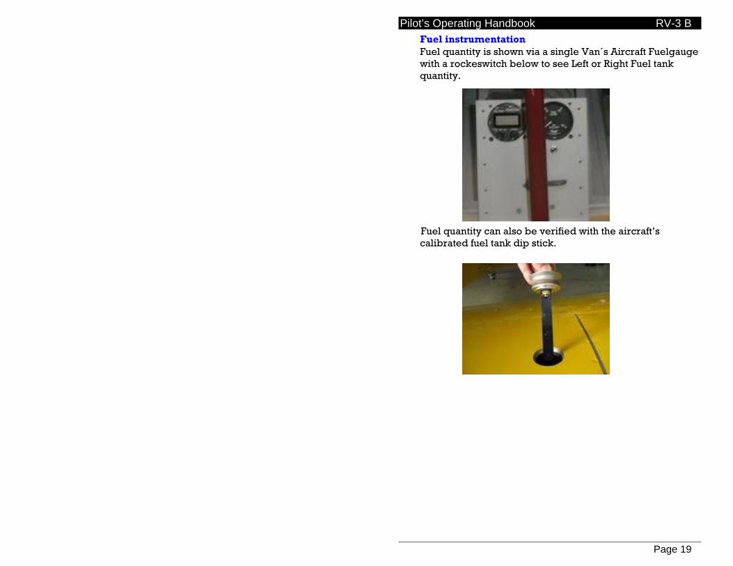
Fuel instrumentation Fuel quantity is shown via a single Van´s Aircraft Fuelgauge with a rockeswitch below to see Left or Right Fuel tank quantity. Fuel quantity can also be verified with the aircraft’s calibrated fuel tank dip stick.

Pilot’s Operating Handbook RV-3 B
Page 20
Electrical system The electrical system is 12 volt DC and conventional in basic configuration with a modern recombinant gas battery and engine driven alternator.. All major devices are on separate circuits, as are most instruments, to provide excellent fault tolerance and easy troubleshooting. Single point ground architecture has been employed for the same reasons and also to reduce the possibility of system noise. Fuse blocks Most electrical items are supplied power and fused via two ATO / ATC standard 1/4" blade type fuse blocks located just behind the panel on the right side of the cockpit.
Main fuse block:
15A Boost fuel
pump
10A Lights
10A Aux power plug
Avionics fuse block:
2A (spare fuse)
2A (spare fuse)
2A GPS
3A Transponder
3A Com radio
Avionics All avionics are supplied 12 volts DC via the panel mounted avionics master breaker/switch that in turn energizes the Avionics fuse block indicated above.

Pilot’s Operating Handbook RV-3 B
Page 21
Lighting
Personal Locator Beacon
Pilot’s Operating Handbook RV-3 B
Page 22
Quick Reference Operating Instructions

Pilot’s Operating Handbook RV-3 B
Page 23
Maintenance
Engine Information Aero Sport Power (Superior/Lycoming)
O-320 C3B
Compression ratio: 7.0-1 Oil pressure: 25-95 psi Oil Sump Capacity: 8 US quarts Minimum safe quantity in sump:
2 US quarts
Recommended add point: 5 US quarts Recommended oils:
Average Ambient temperature
MIS-L-22851 Ashless Dispersant Grades
All temperatures SAE 15W50, 20W50 Above 80º F. SAE 60 Above 60º F. SAE 50 30º F to 90º F. SAE 40 0º F. to 70º F. SAE 20
Oil filter: Champion CH48108-1 Idle speed: 650 rpm Spark Plugs: Unison UREM37BY
Champion REM37BY Gap: .016-.022” Torque: 420 in-lb. Lead nut torque: 80-90 in-lb. Alternator belt: Gates #7355 or equivalent,
3/8” x 35.5” NOTE: Dipstick is calibrated with filter, cooler full.
Pilot’s Operating Handbook RV-3 B
Page 24
Maintenance schedule
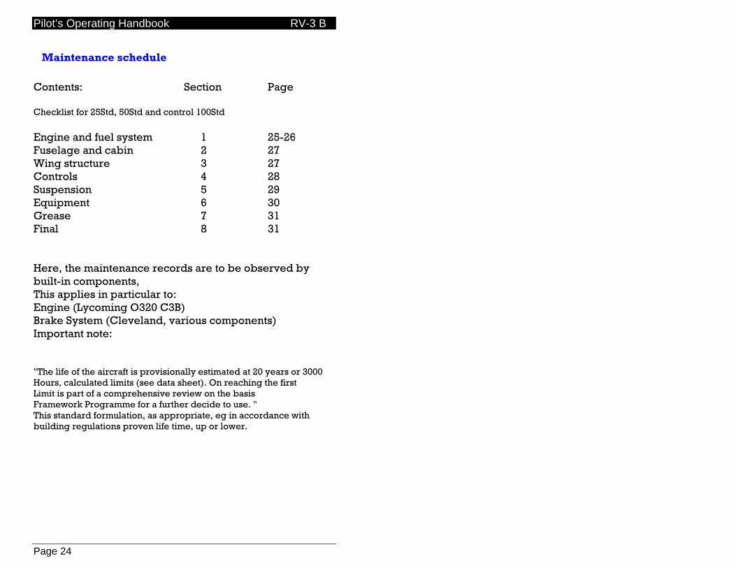
Contents: Section Page Checklist for 25Std, 50Std and control 100Std Engine and fuel system 1 25-26 Fuselage and cabin 2 27 Wing structure 3 27 Controls 4 28 Suspension 5 29 Equipment 6 30 Grease 7 31 Final 8 31 Here, the maintenance records are to be observed by built-in components, This applies in particular to: Engine (Lycoming O320 C3B) Brake System (Cleveland, various components) Important note: "The life of the aircraft is provisionally estimated at 20 years or 3000 Hours, calculated limits (see data sheet). On reaching the first Limit is part of a comprehensive review on the basis Framework Programme for a further decide to use. " This standard formulation, as appropriate, eg in accordance with building regulations proven life time, up or lower.
Pilot’s Operating Handbook RV-3 B
Page 25
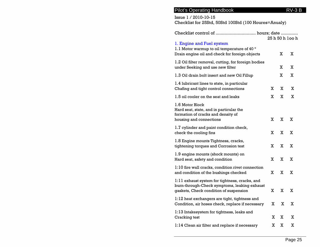
Issue 1 / 2010-10-15 Checklist for 25Std, 50Std 100Std (100 Houres=Anualy) Checklist control of ............................... hours; date ............. 25 h 50 h 1oo h 1. Engine and Fuel system 1.1 Motor warmup to oil temperature of 40 ° Drain engine oil and check for foreign objects X X
1.2 Oil filter removal, cutting, for foreign bodies under Seeking and use new filter X X
1.3 Oil drain bolt insert and new Oil Fillup X X
1.4 lubricant lines to state, in particular Chafing and tight control connections X X X
1.5 oil cooler on the seat and leaks X X X
1.6 Motor Block Hard seat, state, and in particular the formation of cracks and density of housing and connections X X X
1.7 cylinder and paint condition check, check the cooling fins X X X
1.8 Engine mounts Tightness, cracks, tightening torques and Corrosion test X X X
1.9 engine mounts (shock mounts) on Hard seat, safety and condition X X X
1:10 fire wall cracks, condition rivet connection and condition of the bushings checked X X X
1:11 exhaust system for tightness, cracks, and burn-through-Check symptoms, leaking exhaust gaskets, Check condition of suspension X X X
1:12 heat exchangers are tight, tightness and Condition, air hoses check, replace if necessary X X X
1:13 Intakesystem for tightness, leaks and Cracking test X X X
1:14 Clean air filter and replace if necessary X X X

Pilot’s Operating Handbook RV-3 B
Page 26
25 h 50 h 1oo h 1:15 compression test X
1:16 baffles on the seat, chafing, Cracking and condition of the seals examined X X X
1:17 clean spark plugs, ceramic parts and Connections to the integrity and corrosion X X
1:18 Setting the electrode gap (0.4 - 0.5 mm) Renew if necessary X X
1:19 Install spark plugs 1:20 (tightening torque 40 Nm) X X
1:20 Ignition condition and state of Check bushings X X X
1:21 magnetos on state (housing plans, Traces of oil) examine X X X
1:22 Setting the ignition timing 25 v OT X X
1:24 check valve rocker and feathers X X
1:25 starter for wear and tightness test X X X
1:26 ring gear and pinion for wear X X X
1:27 Check condition of generator X X X
1:28 V-belt tension and condition X X X
1:29 propeller for damage control Defects in painting X X X
1:30 Propeller runout X X
1:31 spinner for wear and tightness test X X X
1:32 fuel hoses for condition and leaks X X X
1:33 fuel filter (inside) X X X
1:34 carburetor and solid state cultivation Check X X X
1:35 carburetor ports Control X X X
1:36 fuel pump for wear and tightness test X X X
Pilot’s Operating Handbook RV-3 B
Page 27
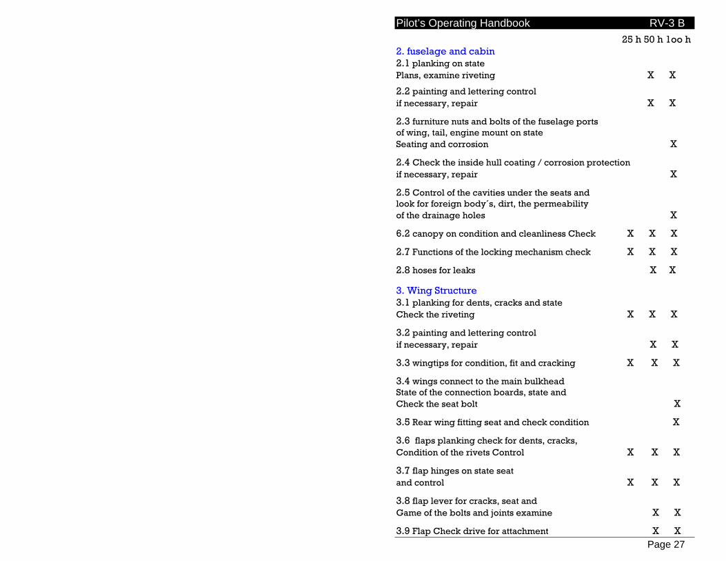
25 h 50 h 1oo h 2. fuselage and cabin 2.1 planking on state Plans, examine riveting X X
2.2 painting and lettering control if necessary, repair X X
2.3 furniture nuts and bolts of the fuselage ports of wing, tail, engine mount on state Seating and corrosion X
2.4 Check the inside hull coating / corrosion protection if necessary, repair X
2.5 Control of the cavities under the seats and look for foreign body´s, dirt, the permeability of the drainage holes X
6.2 canopy on condition and cleanliness Check X X X
2.7 Functions of the locking mechanism check X X X
2.8 hoses for leaks X X
3. Wing Structure 3.1 planking for dents, cracks and state Check the riveting X X X
3.2 painting and lettering control if necessary, repair X X
3.3 wingtips for condition, fit and cracking X X X
3.4 wings connect to the main bulkhead State of the connection boards, state and Check the seat bolt X
3.5 Rear wing fitting seat and check condition X
3.6 flaps planking check for dents, cracks, Condition of the rivets Control X X X
3.7 flap hinges on state seat and control X X X
3.8 flap lever for cracks, seat and Game of the bolts and joints examine X X
3.9 Flap Check drive for attachment X X

Pilot’s Operating Handbook RV-3 B
Page 28
25 h 50 h 1oo h 4. Controls 4.1 tail surfaces, rudders and flaps on Stone chips, cracks, deformation and loose Riveting check X X X
4.2 Touch up paint if necessary X X
4.3 tightly fitted to the spar fittings on the Fuselage check X
4.4 Control system well running, game Rowing and trim to consider while doing on friction the oars, bumpers and ropes X X X
4.5 Control Stick seat, control for play Check bolts on seat X X
4.6 Control Rod and elevator Rod ends have play, easy action and seat Check the bolts X X
4.7 Cross-lever and the elevator State and fastening X
4.8 Pedal lever for cracks and internal clearance Check, Check for friction points X X
4.9 Check the control cables wire breaks Cable outlet for wear Connections to the rudder pedals and examine X X
4.10 aileron, rudder and elevator control surfaces to Ease, check out and attacks X X
4.11 trim to wear on the bushings, Pin play and actuation force test X X
Pilot’s Operating Handbook RV-3 B
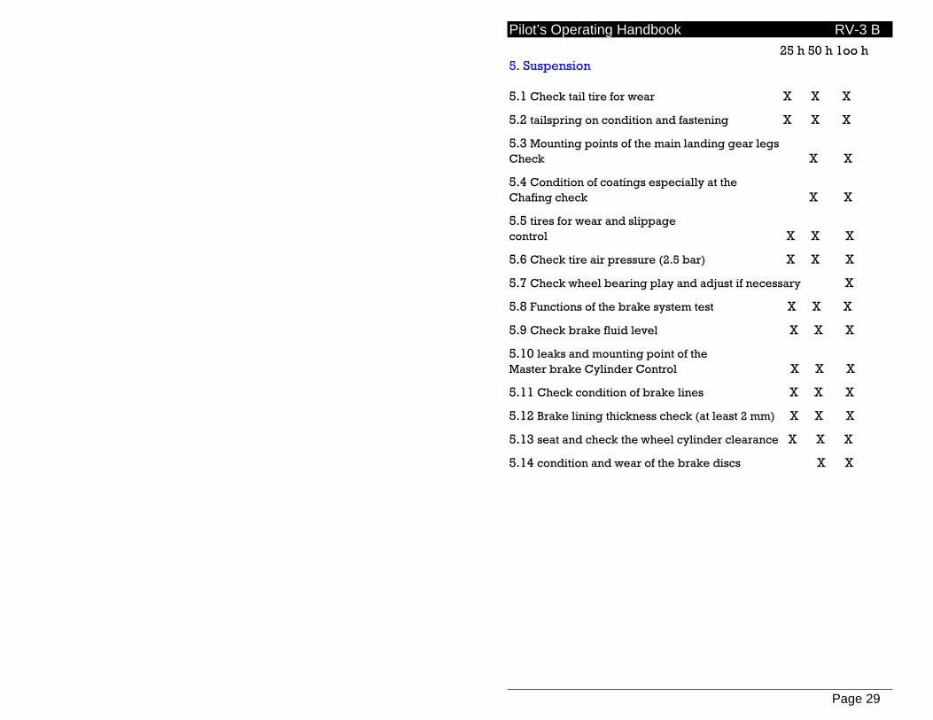
Page 29
25 h 50 h 1oo h 5. Suspension 5.1 Check tail tire for wear X X X
5.2 tailspring on condition and fastening X X X
5.3 Mounting points of the main landing gear legs Check X X
5.4 Condition of coatings especially at the Chafing check X X
5.5 tires for wear and slippage control X X X
5.6 Check tire air pressure (2.5 bar) X X X
5.7 Check wheel bearing play and adjust if necessary X
5.8 Functions of the brake system test X X X
5.9 Check brake fluid level X X X
5.10 leaks and mounting point of the Master brake Cylinder Control X X X
5.11 Check condition of brake lines X X X
5.12 Brake lining thickness check (at least 2 mm) X X X
5.13 seat and check the wheel cylinder clearance X X X
5.14 condition and wear of the brake discs X X
Pilot’s Operating Handbook RV-3 B
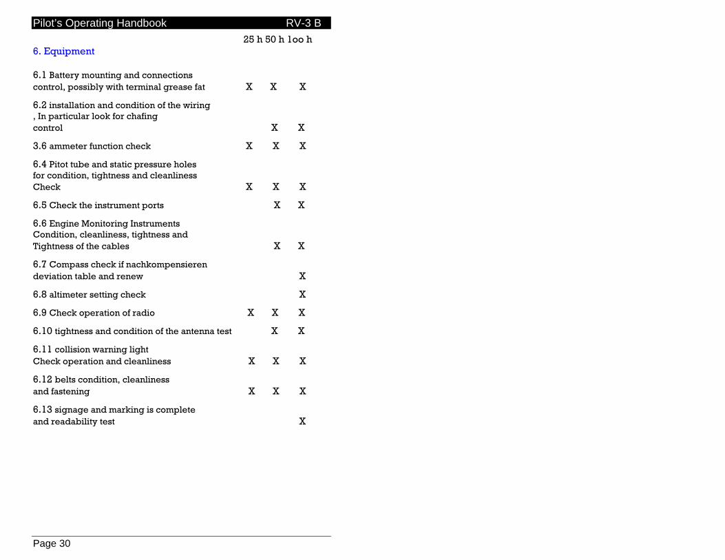
Page 30
25 h 50 h 1oo h 6. Equipment 6.1 Battery mounting and connections control, possibly with terminal grease fat X X X
6.2 installation and condition of the wiring , In particular look for chafing control X X
3.6 ammeter function check X X X
6.4 Pitot tube and static pressure holes for condition, tightness and cleanliness Check X X X
6.5 Check the instrument ports X X
6.6 Engine Monitoring Instruments Condition, cleanliness, tightness and Tightness of the cables X X
6.7 Compass check if nachkompensieren deviation table and renew X
6.8 altimeter setting check X
6.9 Check operation of radio X X X
6.10 tightness and condition of the antenna test X X
6.11 collision warning light Check operation and cleanliness X X X
6.12 belts condition, cleanliness and fastening X X X
6.13 signage and marking is complete and readability test X
Pilot’s Operating Handbook RV-3 B
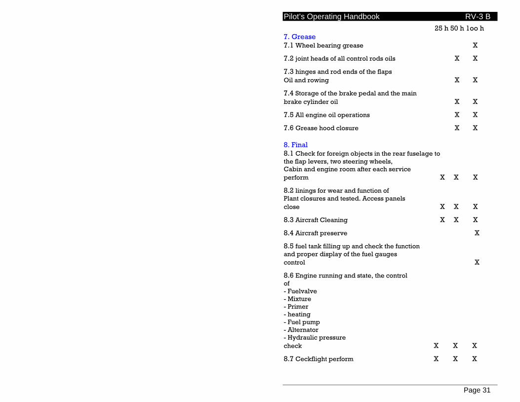
Page 31
25 h 50 h 1oo h 7. Grease 7.1 Wheel bearing grease X
7.2 joint heads of all control rods oils X X
7.3 hinges and rod ends of the flaps Oil and rowing X X
7.4 Storage of the brake pedal and the main brake cylinder oil X X
7.5 All engine oil operations X X
7.6 Grease hood closure X X 8. Final 8.1 Check for foreign objects in the rear fuselage to the flap levers, two steering wheels, Cabin and engine room after each service perform X X X
8.2 linings for wear and function of Plant closures and tested. Access panels close X X X
8.3 Aircraft Cleaning X X X
8.4 Aircraft preserve X
8.5 fuel tank filling up and check the function and proper display of the fuel gauges control X
8.6 Engine running and state, the control of - Fuelvalve - Mixture - Primer - heating - Fuel pump - Alternator - Hydraulic pressure check X X X
8.7 Ceckflight perform X X X
Pilot’s Operating Handbook RV-3 B
Page 32
Propeller maintenance Maintenance to be performed in accordance with manufacturer’s recommendations as detailed in the propeller Owner’s Manual
Pilot’s Operating Handbook RV-3 B
Page 33
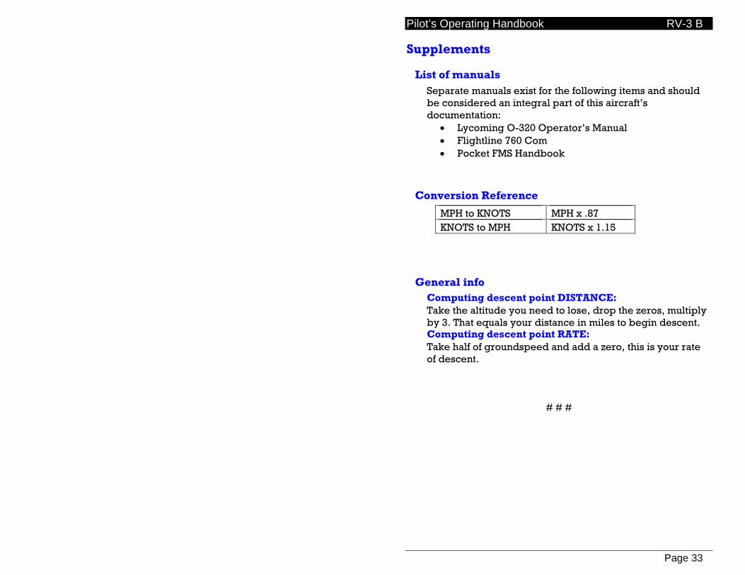
Supplements
List of manuals Separate manuals exist for the following items and should be considered an integral part of this aircraft’s documentation:
• Lycoming O-320 Operator’s Manual • Flightline 760 Com • Pocket FMS Handbook
Conversion Reference
MPH to KNOTS MPH x .87 KNOTS to MPH KNOTS x 1.15
General info Computing descent point DISTANCE: Take the altitude you need to lose, drop the zeros, multiply by 3. That equals your distance in miles to begin descent. Computing descent point RATE: Take half of groundspeed and add a zero, this is your rate of descent.
# # #