pima county subdivision and development street … · 2016 pima county subdivision and development...
TRANSCRIPT

2016
Pima County Subdivision and Development Street Standards
Applicable to projects submitted on or after May 1, 2016

2016 Pima County Subdivision and Development Street Standards
1 |
TABLE OF CONTENTS
1 INTRODUCTION ....................................................................................................... 4
1.1 PURPOSE......................................................................................................................................................... 4
1.2 APPLICATION ............................................................................................................................................... 4
1.3 LIST OF REFERENCES ................................................................................................................................ 5
2 DEVELOPMENT CLASSIFICATION ...................................................................... 6
2.1 RESIDENTIAL SUBDIVISIONS .................................................................................................................. 7
RURAL RESIDENTIAL SUBDIVISIONS .............................................................................................................. 8
URBAN RESIDENTIAL SUBDIVISIONS .............................................................................................................. 8
CONSERVATION SUBDIVISIONS........................................................................................................................ 9
2.2 COMMERCIAL AND INDUSTRIAL DEVELOPMENTS ........................................................................ 9
3 TRAFFIC AND SAFETY ......................................................................................... 10
3.1 TRAFFIC STUDIES ..................................................................................................................................... 10
3.2 SIGHT DISTANCE ....................................................................................................................................... 16
3.3 TRAFFIC CALMING ................................................................................................................................... 21
3.4 STREET LIGHTING .................................................................................................................................... 22
3.5 STREET SIGNING AND PAVEMENT MARKING ................................................................................. 23
3.6 HORIZONTAL CLEARANCE TO OBSTRUCTIONS ............................................................................ 23
3.7 TRAFFIC BARRIERS .................................................................................................................................. 24
3.8 HANDRAILS ................................................................................................................................................. 25
3.9 TRANSIT GUIDELINES ............................................................................................................................. 25
4. STREET DESIGN .................................................................................................... 27

2016 Pima County Subdivision and Development Street Standards
2 |
4.1 STREET CLASSIFICATION ...................................................................................................................... 27
4.2 GENERAL DEVELOPMENT REQUIREMENTS .................................................................................... 28
4.3 STREET LAYOUT AND CONNECTIVITY.............................................................................................. 29
CONNECTIVITY STANDARDS ........................................................................................................................... 30
4.4 STREET CROSS SECTIONS ...................................................................................................................... 31
4.5 SIDESLOPES ................................................................................................................................................. 34
4.6 AUXILIARY LANES .................................................................................................................................... 34
4.7 DESIGN CONTROLS ................................................................................................................................... 35
4.8 STUB STREETS AND CUL-DE-SACS ....................................................................................................... 36
4.9 MEDIANS AND MEDIAN ISLANDS ......................................................................................................... 36
4.10 GATED ENTRIES......................................................................................................................................... 37
4.11 SURVEY MONUMENTATION .................................................................................................................. 38
4.12 UTILITIES ..................................................................................................................................................... 39
4.13 LANDSCAPE ................................................................................................................................................. 40
4.14 HORIZONTAL ALIGNMENT .................................................................................................................... 40
GENERAL DESIGN CONSIDERATIONS............................................................................................................ 41
HORIZONAL CURVES ......................................................................................................................................... 42
HORIZONAL SIGHT LINE OFFSET .................................................................................................................... 43
4.15 VERTICAL ALIGNMENT .......................................................................................................................... 44
GRADES ................................................................................................................................................................. 45
VERTICAL CURVE LENGTH .............................................................................................................................. 45
4.16 INTERSECTIONS ........................................................................................................................................ 47
INTERSECTION ALIGNMENT ............................................................................................................................ 47
INTERSECTION SPACING................................................................................................................................... 48
INTERSECTION RETURN RADII ........................................................................................................................ 49
ROUNDABOUTS ................................................................................................................................................... 50
4.17 PAVEMENT DESIGN .................................................................................................................................. 51
4.18 DRAINAGE ................................................................................................................................................... 53
STREET DRAINAGE ............................................................................................................................................. 54
CURB OPENINGS.................................................................................................................................................. 55
CURB SCUPPERS .................................................................................................................................................. 56
CATCH BASINS .................................................................................................................................................... 56

2016 Pima County Subdivision and Development Street Standards
3 |
STORMWATER HARVESTING WITHIN THE RIGHT-OF-WAY .................................................................... 57
ROADSIDE CHANNELS AND DITCHES ........................................................................................................... 58
CROSS DRAINAGE ............................................................................................................................................... 59
CULVERTS ............................................................................................................................................................ 60
AT-GRADE CROSSINGS FOR URBAN RESIDENTIAL, COMMERCIAL AND INDUSTRIAL
SUBDIVISIONS ..................................................................................................................................................... 62
AT-GRADE CROSSINGS FOR RURAL RESIDENTIAL SUBDIVISIONS ....................................................... 63
5 COMMERCIAL AND INDUSTRIAL SITE DESIGN ........................................... 65
5.1 DRIVEWAY LOCATION ............................................................................................................................ 65
5.2 DRIVEWAY DESIGN .................................................................................................................................. 67
5.3 DESIGN OF PARKING AREAS ................................................................................................................. 70
6 ADMINISTRATION OF THE STANDARDS ...................................................... 78
6.1 STAFF INTERPRETATION AND MODIFICATIONS ........................................................................... 78
6.2 SDSS MODIFICATION COMMITTEE ..................................................................................................... 78
6.3 MODIFICATIONS AND INTERPRETATIONS ....................................................................................... 80
6.4 REQUESTS FOR MODIFICATIONS AND INTERPRETATIONS ....................................................... 80
6.5 COUNTY ENGINEER AND CHIEF BUILDING OFFICIAL ACTIONS ON MODIFICATIONS
AND INTERPRETATIONS REQUESTS ................................................................................................... 81
6.6 MODIFICATIONS TO THESE STANDARDS.......................................................................................... 81
7 STANDARD DETAILS AND CROSS SECTIONS ............................................... 82
8 APPENDIX……………………………………………………………………………………..105
9 REFERENCES…………………………………………………………………………………108

2016 Pima County Subdivision and Development Street Standards
4 |
1 INTRODUCTION
1.1 PURPOSE
These standards have been adopted by Pima County to guide planners and engineers in the
preparation of subdivision plats and commercial/industrial site plans that are consistent
with the Pima County Comprehensive Plan, other Pima County standards, and the latest
State of Arizona and national standards.
The requirements set forth herein are intended to provide for the design and quality
construction of roadway systems that can handle vehicular, pedestrian and bicycle traffic in
an effective and efficient manner, both within the development and at the interface with
the existing roadway network. This manual incorporates complete streets sustainable and
low impact development which supports accessible, livable and attractive communities.
Providing context sensitive transportation infrastructure that is sustainable, accessible and
durable is key to creating these communities.
1.2 APPLICATION
These standards apply to roadway construction, reconstruction or rehabilitation related to
residential or commercial subdivisions or developments within unincorporated Pima
County. Both public and private roadways are subject to this regulation, as these roadways
are traveled by the general public regardless of whether the responsibility for safety,
control and maintenance of the roadway is public or private.
It is not the intent of Pima County to limit design to the requirements prescribed herein if
the objectives contained in the above listed purpose statement can be achieved by other
recognized engineering practices and performance based approaches. Submittal of
alternative performance based designs aligned with the objectives outlined above is
acceptable and will be reviewed on a case by case basis.
In order to assist developers with deferring block plat spine infrastructure first-costs to
facilitate opening master-planned communities, certain requirements in this standard may
be deferred until a determined volume threshold is met. Examples of requirements include
all-weather crossings, intersection controls and drainage infrastructure. However, and in

2016 Pima County Subdivision and Development Street Standards
5 |
order to approve deferments under this clause, the applicant shall demonstrate that the
deferred elements do not compromise the overall design from a functional, operational,
and maintenance perspective. Approved deferments shall be memorialized in a
development agreement.
1.3 LIST OF REFERENCES
Many of the requirements presented in this manual are based on applicable references
published by local, state and national agencies and organizations. A listing of those
references is presented in the appendix. The designer should reference the latest edition of
any reference manual.

2016 Pima County Subdivision and Development Street Standards
6 |
2 DEVELOPMENT CLASSIFICATION
This chapter presents the criteria used to classify each development, in part or as a whole,
as rural residential, urban residential, conservation residential, or commercial/industrial.
It is recommended that developers and design engineers meet with Pima County staff to
discuss the proposed project prior to submittal of rezoning applications, development
permits, or subdivision plats. This is imperative if the development meets any of the
following criteria:
The proposed project will have direct access to a street shown on the Major Streets
Plan.
The project will generate Average Daily Traffic of 1,000 vehicles or more. For
residential subdivisions, this is equivalent to approximately 100 residential units.
The project will impact regulatory floodplains, erosion hazard areas, or mapped
riparian habitat; or flows from proposed improvements alter existing drainage
patterns.
The project will disturb existing vegetation, particularly native vegetation protected by
state or federal law.
This type of meeting will provide an opportunity to coordinate the development with
Capital Improvement Projects (CIP) in the vicinity of the project, and it will help design
engineers better prepare their submittal to reduce project review time. These meetings
may be scheduled through the Development Services Department.
There may be cases in which a development cannot be clearly classified into the categories
presented here. If that is the case, Pima County will determine the classification of the
proposed development based on the prevailing conditions and applicable criteria. Note that
certain developments may encompass both residential and commercial uses. In those
cases, the residential portion of the development must follow the residential standards and
the commercial portion must follow the standards for commercial developments.

2016 Pima County Subdivision and Development Street Standards
7 |
2.1 RESIDENTIAL SUBDIVISIONS
As a general rule, residential subdivisions are those where property is used for dwellings,
regardless of the zoning classification, and the lots individually access a local street. The
exceptions to the rule are condominiums and other multi-family subdivisions that are
similar to commercial and industrial developments in terms of access lanes and parking,
among other elements. Therefore, condominiums, and other multi-family subdivisions may
use the commercial development standards presented in this manual.
Based on criteria such as development density, drainage patterns and environmental
preservation, this manual recognizes two main types of residential subdivisions: urban and
rural. The features of each type of subdivision, as well as the criteria for categorizing
residential subdivisions as rural or urban is discussed here and illustrated below in Figure
2.1. Besides the two main types of residential subdivisions, Pima County recognizes a
special type of subdivision referred to as a “conservation subdivision”.
Figure 2.1: Flowchart for Residential Subdivision Classification

2016 Pima County Subdivision and Development Street Standards
8 |
RURAL RESIDENTIAL SUBDIVISIONS
Rural residential subdivisions are characterized by relatively large lots, considerably
spaced driveways (low driveway density) and minimal disturbance to the natural
environment in terms of grading, drainage patterns, wildlife and native vegetation. A
residential subdivision shall be classified as rural for the purpose of this manual if it meets
all of the following three conditions:
The typical minimum lot size is 16,000 square feet
AND
The typical minimum lot width is 80 feet as defined in Chapter 18.03 of the Pima County
Code1
AND
The subdivision is not mass graded. Mass grading is the process of grading the
subdivision streets and lots or building pads at the same time. A subdivision is not
mass graded if individual grading permits are obtained for each lot as part of the
building permit process.
URBAN RESIDENTIAL SUBDIVISIONS
The lots in urban residential subdivisions are generally smaller than in rural subdivisions.
In addition, driveways are more closely spaced (high driveway density) and there are
significant changes to the natural environment in terms of grading, drainage patterns,
wildlife and native vegetation. In general, residential subdivisions that are not classified as
rural shall be classified as urban. Specifically, a residential subdivision shall be categorized
as urban for the purpose of this manual if it meets at least one of the following conditions:
The minimum lot size is less than 16,000 square feet
OR
2016 Pima County Subdivision and Development Street Standards
9 |
The minimum lot width is less than 80 feet as defined in Chapter 18.03 of the Pima
County Code1.
OR
The subdivision is mass graded. Mass grading is the process of grading the subdivision
streets and lots at the same time.
CONSERVATION SUBDIVISIONS
Conservation subdivisions promote the establishment of conservation natural areas and,
where possible and practicable, support interconnected, continuous, and integrated open
space systems within an area, particularly when located contiguous to public preserves. In
order to achieve the goal of conservation, a special set of street standards has been
developed for conservation subdivisions and is described in Chapter 4; however their use
is restricted to subdivisions that comply with Chapter 18.09.100 of the Pima County Code1.
Conservation subdivisions shall generally comply with the requirements for rural
residential subdivisions; however, in situations where the minimum lot size, lot width or
the type of grading fall within the criteria defined for urban residential subdivisions, the
urban standards must be used.
2.2 COMMERCIAL AND INDUSTRIAL DEVELOPMENTS
The development of any land for commercial, industrial, or any other non-residential use
shall follow the commercial development standards. Subdivisions for non-residential uses
shall use the commercial/industrial street standards described in chapter 4. Apartments,
condominiums and other multi-family residences of four or more units that use a system of
parking and access lanes and common parking areas shall be treated as commercial
developments. However, and contingent on average daily traffic (ADT), multi-family
residences may use residential subdivision standards for off-site improvements when
connecting to a local residential street.
2016 Pima County Subdivision and Development Street Standards
10 |
3 TRAFFIC AND SAFETY
3.1 TRAFFIC STUDIES
Development-generated traffic and access needs for proposed subdivisions and
developments must be evaluated to determine its impact on the adjacent roadway
network. This impact, and requirements for off-site improvements to mitigate those
impacts is determined by a Traffic Impact Study (TIS) or Traffic Memorandum (TM). A brief
letter report for small projects may be submitted in lieu of a TM or TIS if approved by Pima
County.
Traffic Impact Study
A Traffic Impact Study is required for projects that meet one or more the following
conditions:
The project generates 100 or more gross trips during the morning (AM) and/or
afternoon (PM) peak hour.
There is a previous TIS for the project that is more than 3 years old and:
Additional developments have been approved in the vicinity of the project that
impact the site, or
Current traffic has increased by 15% or more over the traffic volumes shown in the
TIS, or
A Capital Improvement Project (CIP) project is within ¼ mile of the proposed
project and involves changes to lane configurations, traffic signals, roadway lighting,
pedestrian/bicycle facilities, or drainage improvements.
Traffic Memorandum
A Traffic Memorandum is required for projects that generate less than 100 gross trips
during the AM and/or PM peak hour and meet one or more of the following conditions:
The development triggers the Left-Turn Lane Warrants or Right-Turn Lane Warrants as
outlined in Section 4.6.

2016 Pima County Subdivision and Development Street Standards
11 |
The development has an access point connecting to a Pima County maintained roadway
within 500 feet of an interstate interchange.
The development has an access point connecting to a Pima County maintained roadway
within 300 feet of a railroad crossing.
The development generates more than 25 trips during the peak hour and has an access
point connecting to a Pima County maintained roadway within 500 feet of an
intersection that has a three year crash rate 10% greater than the three year system
crash rate. The intersection crash rates/system crash rates can be obtained from the
latest Unsignalized Intersections and Signalized Intersections reports on the Pima
County Department of Transportation website.
The development generates more than 25 trips during the peak hour and has an access
point connecting to a Pima County maintained roadway segment that has a three or five
year crash rate 10% greater than the three year system crash rate. The segment crash
rates/system crash rates can be obtained from the latest Low Volume Road Segments
(≤ 10,000 VPD) and High Volume Road Segments (>10,000 VPD) reports on the Pima
County Department of Transportation website.
There is a previous TM that is more than 3 years old and:
Additional developments have been approved in the vicinity of the project that
impact the site, or
Current traffic has increased by 15% or more over the traffic volumes shown in the
TM, or
A CIP project is within ¼ mile of the proposed project and involves changes to lane
configurations, traffic signals, roadway lighting, pedestrian/bicycle facilities, or
drainage improvements.
General Requirements for TIS and TM
Criteria for formatting and scope of the TIS and TM are posted on the County website.
2016 Pima County Subdivision and Development Street Standards
12 |
The number of trips generated is to be calculated using the latest edition of the Institute
of Transportation Engineers Trip Generation Manual, or from a trip generator curve
that has been developed specifically for that development and approved by Pima
County. Trip factors based on proposed land use and other useful information is posted
on the Development Services website to aid in the trip generation calculation and the
TM threshold determination. Please note the Chief Building Official may issue a
Certificate of Occupancy limiting the number of authorized building occupants
commensurate with the input information used for trip generation. It is therefore
strongly suggested that trip generation/occupancy data not be underestimated in order
to preserve the full occupant loading of buildings as determined by the building code.
Hourly volume information for traffic counts can be obtained from the PAG website at
http://gismaps.pagnet.org/trafficcounts.
A project that is an addition to an existing use, or a previously approved project that
resubmits for modifications or changed use, is subject to these requirements. The trip
generation of the existing use shall be added to the trip generation of the addition to
determine the gross trips.
A project that has a prior approved TM may submit a revision to the TM unless the
gross trip generation is 100 or more, in which case a TIS is required.
Any change or update to an approved TIS/TM shall include the originally approved
TIS/TM with the update submittal as reference material.
The TIS or TM must be prepared under the supervision of and be sealed by a registered
professional engineer in the State of Arizona who has demonstrated proficiency in
traffic engineering and transportation planning.
Scope Requirements for a TIS
TIS Categories: Based on the size and phasing of the proposed development, the TIS
categories shown in Table 3.1 have been established as the basis to determine the study
area and horizon.

2016 Pima County Subdivision and Development Street Standards
13 |
Table 3.1: TIS Categories
TIS Category Morning or Afternoon Peak Hour
Trips1
1 100-499
2 500-999
3 ≥ 1000 Single Phase Development
4 ≥ 1000 Multi-Phase Development
1The peak hour with the greatest number of trips should be utilized to determine the TIS category
Study Area and Study Horizon: The minimum study area and study horizon shall be
determined by project type and size in accordance with Table 3.2. The study area for
the proposed development shall include traffic controlled intersections, site access
driveways and major unsignalized intersections. Unsignalized intersections where at
least one of the intersecting streets is a collector or arterial are considered major
unsignalized intersections.
Table 3.2 Design Attributes by Functional Class
TIS Category Study Horizons1 Minimum Study Area2
1
1. Opening year 1. Site access driveways2. All signalized intersections
and/or major unsignalizedintersections within 1/4 mile
2
1. Opening year2. Five years after
opening
1. Site access driveways2. All signalized intersections
and/or major unsignalizedintersections within 1/2 mile
3
1. Opening year2. Five years after
opening3. Twenty years after
opening
1. Site access driveways2. All signalized intersections
and/or major unsignalizedintersections within 1 mile
4
1. Opening year of eachphase
2. Five years after build-out
3. Twenty years afterbuild-out
1. Site access driveways2. All signalized intersections
and/or major unsignalizedintersections within 1 mile
1. Assume full occupancy and build-out for single phase developments
2. An enlarged study area may be required as discussed in 3.2.2.3

2016 Pima County Subdivision and Development Street Standards
14 |
Crush volumes: Developments where the peak volume occurs in less than one hour
(such as schools) should use a peak hour factor (PHF) of 0.55 or less and account for
peak loads through internal site circulation design. The ITE publication School Site
Planning, Design, and Transportation provides further information related to schools.
Analysis time period: Both the morning and afternoon weekday peak hours need to be
analyzed. If the peak traffic hour in the study area occurs during a time period other
than normal peak travel periods, those peak hours must also be analyzed in addition to
the normal peak travel periods.
Data Collection Requirements: All data is to be collected in accordance with the latest
edition of the ITE Manual of Transportation Engineering Studies or as directed by the
Traffic Engineering Division Manager, if not specifically covered in the ITE manual.
Turning movement counts shall be obtained for all existing cross-street intersections to
be analyzed during morning and evening peak periods as identified in Table 3.2.
Turning movement counts associated with developments that have crush volumes
should be taken at five minute intervals. Available turning movements may be
extrapolated a maximum of three years with concurrence of the Traffic Engineering
Division Manager. The current and projected daily traffic volumes shall be presented in
the report.
Trip Generation: The latest edition of ITE’s Trip Generation Manual shall be used for
selecting trip generation rates. The guidelines contained in the Trip Generation Manual
shall be used to determine whether the average trip generation rate or equation should
be used. Other rates may be used with the approval of the Traffic Engineering Division
Manager in cases where the Trip Generation Manual does not include trip rates for a
specific land use category, or includes only limited data, or where local trip rates have
been shown to differ from the ITE rates. If the development is a chain development,
then the developer can calculate their own applicable trip generation curve based on
other sites if ITE rates do not apply.

2016 Pima County Subdivision and Development Street Standards
15 |
Trip Projection: The trips must be projected for the study horizon years allocated by the
TIS category.
Trip Distribution and Assignment: Projected trips shall be distributed and added to the
projected non-site traffic on the roadway network. The projected traffic volumes must
be shown for all roadways internal to the development and for all other roadways
within the study area. The specific assumptions and data sources used in deriving trip
distribution and assignment shall be documented by the study.
Capacity Analysis: Level of Service (LOS) shall be computed for signalized and major
unsignalized intersections as identified in Table 3.2, in accordance with the latest
edition of the Highway Capacity Manual. While the use of the operational methodologies
presented in the Highway Capacity Manual is always desirable, analyses such as the
planning method included in the FLDOT Traffic Analysis Handbook are acceptable for
analysis planning of new facilities.
Traffic Signal Needs: Analysis of traffic signal needs shall be provided for all major
collector/major collector and larger intersections per the Manual on Uniform Traffic
Control Devices. If the warrants are not met for the opening year, they should be
evaluated five years after opening for Category 2, 3 and 4 Traffic Impact Studies.
Crash Analysis: An analysis of the five-year crash data within the study area shall be
conducted to determine if the level of safety in terms of crash rates and severity index
needs improvement due to the addition of site traffic.
Queuing Analysis: An analysis shall be conducted for all turn lanes within the study
area.
Improvement Analysis: The roadways and intersections within the study area shall be
analyzed with and without the proposed development to identify any projected impacts
in regard to level of service and safety.

2016 Pima County Subdivision and Development Street Standards
16 |
The minimum design requirements for all intersections and roadway segments shall be
Level of Service (LOS) D with no intersection through lane movement falling below LOS
D and no intersection turning movement falling below LOS E. If the TIS shows that the
impact of a development will bring the LOS below those thresholds during the study
horizon, mitigation alternatives to improve the LOS to at least those thresholds must be
analyzed as part of the study.
If the performance of the existing intersection or roadway is already below those
thresholds (e.g. below LOS D for through movements) the study must also evaluate the
need for turning lanes on all major unsignalized intersections. In addition, if the delay is
increased by 10% more than the existing, mitigation measures must be taken to
decrease the delay to the 10% threshold.
Alternative Modes: Multi-modal conflict points with vehicles must be identified.
Recommendations must be made to facilitate reasonable operation of alternative
modes, especially at the interface with the roadway network.
Additional information regarding scope criteria is posted on the Pima County web site.
3.2 SIGHT DISTANCE
In the design of streets, driveways, and intersections, including roundabouts, both stopping
sight distance, and intersection sight distance, must be considered.
STOPPING SIGHT DISTANCE
Stopping sight distance is a function of design speed and grade. The minimum stopping
sight distance for level ground (grades up to 2%) and for downgrades up to 6% are
presented in Table 3.3. Roundabout designs should be checked to insure that stopping sight
distance is provided at every point within the roundabout and on each entering and exiting
approach.
Refer to the latest edition of AASHTO A Policy on Geometric Design of Highways and Streets2
for information about the effects of grade on stopping sight distance, and how to calculate
stopping sight distance on grades other than those listed below.

2016 Pima County Subdivision and Development Street Standards
17 |
Table 3.3 Stopping Sight Distance
Design Speed (mph) SD (ft)
Grades ≤2%
SD (ft)
2% < Grades ≤ 6%
20 115 120
25 155 165
30 200 215
35 250 275
40 305 335
Source: AASHTO A Policy on Geometric Design of Highways and Streets2
INTERSECTION SIGHT DISTANCE
At intersections, an unobstructed and continuous view of both the intersection and the
intersecting roadway helps drivers avoid conflicts. The sight triangle at each intersection
quadrant must be clear of any visual obstructions including structures, cut slopes,
vegetation, and mounds of earth or rock over 30 inches in height. Sight triangles are
required to be shown on tentative plats, site plans and construction plans with
obstructions in both the horizontal plane and the vertical plane being reviewed. Three
intersection cases are addressed in this manual.
Case 1
The required sight visibility triangle for local to local and local to residential collector
intersections where both streets have a design speed of 25 mph is 185 feet to the left side
and 125 feet to the right side. Figure 3.1 demonstrates how these measurements are
translated into sight visibility triangles measured from the edge of pavement to edge of
pavement.

2016 Pima County Subdivision and Development Street Standards
18 |
Figure 3.1 Local-Local and Local-Residential Collector
Sight Visibility Triangles
Case 2
At intersections where the thru street has two-way traffic separated by a median with no
opening for the side street, only the left side sight visibility triangle, based on the design
speed of the thru street, is required. However, a pedestrian visibility triangle shall be
maintained in place of the right side triangle as indicated in Figure 3.2.
Figure 3.2 Pedestrian Sight Visibility Triangle
Case 3
The required intersection sight distance for vehicles turning onto a major collector,
commercial/industrial collector or arterial shall be calculated in accordance with the
following procedure. For this case, Pima County practice is to consider only the sight
distance required for a left-turning vehicle.
Measure the distance on the major road from the edge of pavement to the first lane
the vehicle can turn into for a left-turn. If there is a right-turn lane on the major road

2016 Pima County Subdivision and Development Street Standards
19 |
to turn onto the minor road being studied, the width of the right-turn lane is not
included in the distance measurement. This distance is indicated as “D,” in figure 3.3.
Figure 3.3 Distance “D” Examples
Utilize the following equation to calculate the intersection sight distance, designated
as “B” in Figure 3.4, required for each approach to the minor road.

2016 Pima County Subdivision and Development Street Standards
20 |
gmajortVB 47.1
where
B = intersection sight distance for a left-turn from stop (feet)
Vmajor = speed limit on the major road (mph)
tg = time gap for the minor road vehicle to enter the major road and make a
left turn (seconds)
If D ≤ 11feet, then tg = 7.5.
If D > 11 feet, then
5.0
225.7
Dt g
If steep grades are involved, or if the design vehicle is other than apassenger car the time gap value must be adjusted per AASHTO A Policyon Geometric Design of Highways and Streets2.
Figure 3.4 Intersection Sight Distance Triangle Examples

2016 Pima County Subdivision and Development Street Standards
21 |
Figure 3.4 Continued
A = The distance from the Decision Point to the center of the closest approach lane to the minor road from the left or the right. The Decision
Point is typically 15 feet from the edge of the major road traveled way, but may be increased to 18 feet depending on the design vehicle. Refer to
AASHTO A Policy on Geometric Design of Highways and Streets for information on roundabout sight distance.
3.3 TRAFFIC CALMING
The goal of traffic calming is to improve roadway safety and overall quality of life in
residential neighborhoods by promoting traffic speeds that are consistent with the design
speed of the street and the character of the development. Traffic calming can be achieved
through the utilization of operational measures, design features or physical barriers that
provide contextual cues which allow drivers to self-enforce slower speeds. This manual has
been developed in such a way that the goals of traffic calming should be achieved by a
combination of appropriate geometric design criteria, street classification and traffic
parameters. Planners, designers and engineers are encouraged, especially in residential
developments, to incorporate additional traffic calming features such as:
Intersection constrictions
Raised intersections or crosswalks (See Detail 3)
Speed tables or speed humps
Chicanes (See Detail 3)

2016 Pima County Subdivision and Development Street Standards
22 |
Medians, especially on curves
Traffic circles (See Details 2 & 3)
Source: Green Infrastructure for Southwestern Neighborhoods
The following manuals provide additional guidance for traffic calming:
Model Design Manual for Living Streets21
Pedestrian Policies and Design Guidelines22
Traffic Calming Library23
3.4 STREET LIGHTING
Street lighting helps to increase and supplement vehicle headlight visibility at night. It also
helps to delineate points and areas of potential conflict and allows improved traffic
operations at times of darkness that may reduce crash frequency and severity.
Street lighting should be considered in the following circumstances:
One of the intersecting streets is a major collector or arterial.
The horizontal or vertical curvature of the roadway or other factors at or leading into
the intersection constitute a confusing or unsatisfactory condition that may be
improved with lighting
Chicanes, when designed properly, are ideal for stormwater harvesting basins to meet the first flush retention requirement and can be incorporated into the on-site drainage plan.

2016 Pima County Subdivision and Development Street Standards
23 |
The location has a marked crosswalk or trail crossing.
The area has residential, commercial or school development on both sides of the road
and these developments are active at night and may result in nighttime pedestrian
crossings.
In determining the appropriateness of a street lighting application, consideration should be
given to the availability of a power source, the nature of the surrounding area and existing
development, and whether the lighting would create a nuisance or hazard based on grade
elevation differences of surrounding areas.
Street lighting plans shall be prepared in conformance with the Pima County Street
Lighting and ITS Conduit Design Manual, Illuminating Engineering Society guides and
practices, and the AASHTO Lighting Guide. Street lighting must conform to the
requirements of the Pima County Outdoor Lighting Code58.
3.5 STREET SIGNING AND PAVEMENT MARKING
Signing and pavement marking plans shall be provided as needed. Signing and pavement
marking submittals must conform to the latest editions of the Pima County Signing Manual,
Pima County Pavement Marking Design Manual and Manual on Uniform Traffic Control
Devices (MUTCD)12.
Signing plans shall include the MUTCD or Pima County specialty sign code, sign size, sign
schematic and sign location. Pavement marking plans shall include pavement marking
code, dimensions and locations, including stations and offsets if available.
3.6 HORIZONTAL CLEARANCE TO OBSTRUCTIONS
URBAN ROADS
When the standard three foot curbway is provided, fixed objects such as utility poles or
boxes, traffic barriers, mailboxes, or fire hydrants are to be placed behind the sidewalk
unless the object has a recognized breakaway feature and does not block sight distance or
is flush mounted and does not present a tripping hazard.

2016 Pima County Subdivision and Development Street Standards
24 |
If the curbway width is increased, such objects may be allowed in the curbway provided
they are offset from the back of curb at least 5 feet, and preferably 8 feet.
RURAL ROADS
Rural roads must provide obstruction free zones that meet or exceed the distances
presented in Table 3.4. These distances are measured from the edgeline, or edge of
pavement if no edgeline is provided.
Table 3.4 Rural Road Horizontal Clearance
Foreslope or Backslope (H:V) Local Street Residential
Collector
Major Collector
6:1 or flatter 10’ 12’ 14’
Steeper than 6:1 to 4:1 12’ 14’ 16’
Source: AASHTO Roadside Design Guide28
3.7 TRAFFIC BARRIERS
Roadside barriers are systems used to shield motorists from natural or man-made
obstacles located along the traveled way and may be used to protect pedestrians and
bicyclists from vehicles under certain conditions. Because of the low design speeds,
barriers are generally not required for local streets; however, engineering judgment must
always be exercised by the designer.
Roadside obstacles and embankments that may warrant shielding by a roadside barrier
require evaluation in accordance with the barrier warranting process identified in the
latest edition of the AASHTO Roadside Design Guide28.
Barrier warrant analysis shall be included with any plan submitted for review and shall
include the location and description of the obstacle, evaluation of the need for a barrier
and the location and design of any proposed barrier.
Barrier and/or guardrail treatment shall be placed at the face of the curb for curbed
roadways and back of shoulder for uncurbed roadways.

2016 Pima County Subdivision and Development Street Standards
25 |
The length of barrier shall meet the recommendations presented in the latest edition of
the AASHTO Roadside Design Guide28.
The selected barrier shall have been crash tested and approved by FHWA, for situations
compatible with the intended use.
Barriers must be installed in accordance with current ADOT standard Specifications
and Drawings. Use of non-ADOT barriers will be reviewed on a case by case basis.
3.8 HANDRAILS
Handrails shall be installed for protection of pedestrians whenever slopes are steeper than
2:1 (H:V) within 3 feet of the walkway or sidewalk and the embankment height is 3 feet or
greater. The design engineer may determine that differences in elevation between the
walkway or sidewalk and nearby terrain under other circumstances may also warrant the
installation of handrail. Handrail shall be built in accordance with PAG Standard Detail 105.
3.9 TRANSIT GUIDELINES
When a project is constructed adjacent to an existing bus stop location or along an existing
bus route, coordination with Sun Tran is required to determine if a new bus stop or
relocation or improvement of an existing bus stop is necessary.
Project plans shall show existing and proposed bus stops, including loading pads,
benches, signs, trash receptacles, bus shelters and bus pullouts.
Sidewalks or multi-use pathways, with interconnecting access ramps, consistent with
the transportation and public accommodation provisions of the ADA, should connect
the bus stop to the nearest intersection, local commercial development or other
passenger destinations, such as educational facilities, senior citizen housing, or medical
facilities.
When a bus stop is constructed on streets that do not include outside curb, the bus stop
and associated pedestrian facilities should be placed as far as possible from the edge of
pavement, in accordance with applicable AASHTO guidelines.

2016 Pima County Subdivision and Development Street Standards
26 |
Further guidance regarding transit facilities can be found in the Pima County Transit
Guidelines for Roadway Design and Construction.
2016 Pima County Subdivision and Development Street Standards
27 |
4. STREET DESIGN
4.1 STREET CLASSIFICATION
Three types of streets are addressed in this manual.
Local streets are low volume undivided roadways with no lane designation that provide
direct access to abutting properties. Service to through traffic movement is discouraged
on local streets.
Residential/commercial collectors provide a combination of mobility and land access
within residential neighborhoods or commercial/industrial developments.
Major collectors provide connectivity from large subdivisions to the arterial roadway
system, and are normally situated at mid-section locations. Given the level of mobility
that they provide in terms of volumes and speed, direct access to adjacent property
from major collectors is limited.
Generally, only local and collector streets are required for the traffic generated by a single
development. However, there may be developments that because of their size, location or
other conditions require improvements to or the construction of an arterial roadway. In
those cases, the design must follow the requirements in the Pima County Roadway Design
Manual3.
The design characteristics for local and collector streets are summarized in Table 4.1. In the
table, segment length is the distance between consecutive breaks in roadway alignment.
The following elements create breaks in the alignment.
Knuckles. See Details 1A and 1B
Sharp horizontal curves with an intersection angle greater than 60 degrees and a radius
not exceeding 300 feet.
Traffic circles. See Detail 2 and Detail 3

2016 Pima County Subdivision and Development Street Standards
28 |
Intersections.
Table 4.1 Summary of Design Characteristics by Street Classification
Parameter Local Street Residential/Commercial
Collector
Major
Collector
REQUIRED CRITERIA
Volume (veh/day) < 1,000 1,000 – 2,500 2,500 – 10,000
Segment Length (mi) < ⅛* ¼ - 1 1 - 3
Design Speed (mph) 25 25-30 35-40
Direct Access to Property Yes No** No
RECOMMENDED CRITERIA
Major Terminus Collector or local
street Arterial or major collector Arterial
Minor Terminus Local street or
turnaround
Residential collector or
local street
Arterial, residential
or major collector
System Continuity Low Medium High
* Subdivisions greater than 1 acre lots can have a segment length of ¼ mile
**Direct access to property can be provided if the maximum segment length is limited to ¼ mile AND the design speed is 25 mph
4.2 GENERAL DEVELOPMENT REQUIREMENTS
All residential, commercial or industrial developments shall provide, legal, paved, all-
weather access to the public roadway system. The developer is responsible for the cost
of connecting the development to the public roadway network.
Individual direct access for residential lots adjacent to major collectors or arterials is
not permitted. All residential lots shall be accessed by internal subdivision streets.

2016 Pima County Subdivision and Development Street Standards
29 |
All subdivision lots shall have a minimum street frontage of 30 feet to allow room for
the driveway and installation of utilities.
If parking is designed to be in the lot driveways, at least 20 feet of driveway length shall
be provided between the back of sidewalk and garage opening to ensure that cars
parked in the driveway do not block the sidewalk.
Common driveways shall serve a maximum of four lots and shall be limited to a
maximum of 150 feet in length to facilitate the provision of municipal services such as
fire protection and trash pick-up.
All roadway infrastructure such as travel lanes, medians, shoulders, curbs, sidewalks
and drainage structures shall be located in public right-of-way or private common area
and not in easements. Easements may be granted for certain cross section elements
such as utilities and slopes.
A 1 foot wide Access Control Easement (ACE) shall be granted to Pima County when it is
determined that vehicular access to or from a development or subdivision should be
prohibited at a particular location.
Connectivity of pedestrian facilities is required in order to provide a Complete Street
system. Additional guidelines regarding pedestrian facilities can be found in AASHTO
Guide for Planning, Design, and Operation of Pedestrian Facitilites25 and the FHWA
PEDSAFE: Pedestrian Safety Guide and Countermeasure Selection System26.
4.3 STREET LAYOUT AND CONNECTIVITY
Pima County promotes a Complete Streets design approach with an interconnected street
system that accommodates all users and modes of travel. An interconnected street system
is beneficial as it:
Promotes public health, safety, and welfare
Provides improved access for emergency and service vehicles

2016 Pima County Subdivision and Development Street Standards
30 |
Connects neighborhoods with one another, neighboring commercial developments and
recreational areas.
Promotes walking, biking, and equestrian activity.
Reduces vehicle miles traveled resulting in better air quality and longevity of the
roadway
CONNECTIVITY STANDARDS
The design of a subdivision shall attempt to provide multiple direct connections in its
local street system without requiring the use of arterial streets and to ensure that each
lot has a secondary means of access. The minimum number of required external
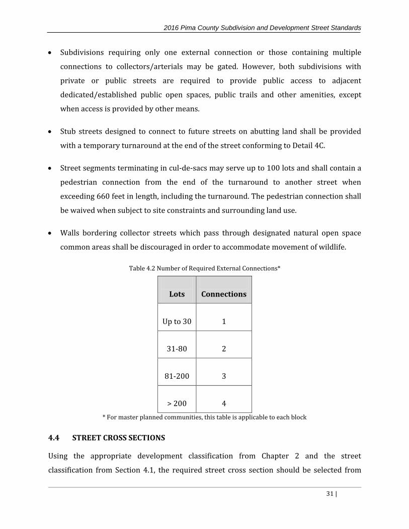
connections to the subdivision is specified in Table 4.2. When required to provide more
than one external connection, the connections shall be spaced in such a manner as to
maximize radial connectivity external to the subdivision without necessitating the use
of arterial streets.
The number of connections required in Table 4.2 may be reduced if the development
boundary contains constraints to include, but not limited to: existing unconnected
development, washes of 100 yr/500CFS or greater, crossings requiring Clean Water Act
Section 404 permits, riparian areas, conservation lands, wildlife linkages, other natural
features, planned lands of incompatible uses, unplanned public lands, and engineering
constraints of similar conditions. In these cases, the proportion of the subdivision
perimeter subject to the constraints would be calculated and the number of required
connections shall be reduced proportionally (e.g., if 1/3 the perimeter of a subdivision
is subject to constraints and Table 4.2 specifies 3 connections for the subdivision, then
the required number of connections may be reduced to 2).
Each subdivision shall incorporate and continue all collector and local streets stubbed
to the boundary of the development by previously approved but unbuilt or existing
developments, except in instances where the stub-out is not accepted as a public street
and the owner or homeowner’s association is prohibiting a connection thereto.
2016 Pima County Subdivision and Development Street Standards
31 |
Subdivisions requiring only one external connection or those containing multiple
connections to collectors/arterials may be gated. However, both subdivisions with
private or public streets are required to provide public access to adjacent
dedicated/established public open spaces, public trails and other amenities, except
when access is provided by other means.
Stub streets designed to connect to future streets on abutting land shall be provided
with a temporary turnaround at the end of the street conforming to Detail 4C.
Street segments terminating in cul-de-sacs may serve up to 100 lots and shall contain a
pedestrian connection from the end of the turnaround to another street when
exceeding 660 feet in length, including the turnaround. The pedestrian connection shall
be waived when subject to site constraints and surrounding land use.
Walls bordering collector streets which pass through designated natural open space
common areas shall be discouraged in order to accommodate movement of wildlife.
Table 4.2 Number of Required External Connections*
Lots Connections
Up to 30 1
31-80 2
81-200 3
> 200 4
* For master planned communities, this table is applicable to each block
4.4 STREET CROSS SECTIONS
Using the appropriate development classification from Chapter 2 and the street
classification from Section 4.1, the required street cross section should be selected from

2016 Pima County Subdivision and Development Street Standards
32 |
Standard Details 8-15. All subdivision streets must be constructed in conformance with the
applicable street cross section.
The minimum dimensions of roadway elements for urban residential streets, rural
residential streets and commercial/industrial streets are summarized in Tables 4.3, 4.4 and
4.5, respectively.
Table 4.3 Standard Element Dimensions for Urban Residential Streets
Local Street Residential
Collector
Major
Collector
Pavement Width 24’1 24’ or 28’2 46’
Travel Lane Not Designated Not Designated 11’
Paved Shoulders Not required Not required 6’
Two-Way Left-Turn
Lane/Median Not required Not required 12’
Turning Lane Not required 12’ 12’
On-Street Parking Yes No No
Cross Slope 2% 2% 2%
1. Local street pavement width shall not exceed 30 feet.
2. Reduced width value for collectors is applicable when traffic calming devices are installed at intervals not to exceed 660 feet
2016 Pima County Subdivision and Development Street Standards
33 |
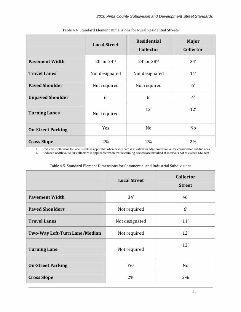
Table 4.4 Standard Element Dimensions for Rural Residential Streets
Local Street Residential
Collector
Major
Collector
Pavement Width 20’ or 24’1 24’ or 28’2 34’
Travel Lanes Not designated Not designated 11’
Paved Shoulder Not required Not required 6’
Unpaved Shoulder 6’ 6’ 4’
Turning Lanes Not required 12’ 12’
On-Street Parking Yes No No
Cross Slope 2% 2% 2%
1. Reduced width value for local streets is applicable when header curb is installed for edge protection or for conservation subdivisions.
2. Reduced width value for collectors is applicable when traffic calming devices are installed at intervals not to exceed 660 feet
Table 4.5. Standard Element Dimensions for Commercial and Industrial Subdivisions
Local Street Collector
Street
Pavement Width 34’ 46’
Paved Shoulders Not required 6’
Travel Lanes Not designated 11’
Two-Way Left-Turn Lane/Median Not required 12’
Turning Lane Not required 12’
On-Street Parking Yes No
Cross Slope 2% 2%

2016 Pima County Subdivision and Development Street Standards
34 |
4.5 SIDESLOPES
All cut and fill slopes shall be constructed in accordance with Chapter 18.81 of the Pima
County Code1 and AASHTO A Policy on Geometric Design of Highways and Streets2.
The Pima County standard for cut and fill sections is a 4:1 slope on urban roadways,
and a 6:1 foreslope and 4:1 backslope on rural roadways.
Cut and fill slopes over 2 feet in height shall be revegetated or stabilized as shown in
Table 4.6. All revegetated areas, as well as the method of irrigation and maintenance
responsibility until final stabilization must be clearly identified in the landscape
plans per the Pima County Landscape manual.
Table 4.6 Treatment methods for cut-fill slopes over 2 feet in height
Cut or Fill Slope (H:V) Treatment
3:1 or less steep Revegetate
Steeper than 3:1 to 2:1 Rock rip-rap with filter fabric
Alternative methods of stabilization may be allowed if certified as stable by a
registered geotechnical engineer, and approved by Pima County.
4.6 AUXILIARY LANES
All access points for a development must be evaluated to determine if an auxiliary right or
left turn is warranted.
Figures A1, A2 and A3 in Appendix A shall be used to determine if an auxiliary lane is
required.
Use of any alternative warrant criteria shall be supported by a traffic analysis and
approved by Pima County.
The Pima County Roadway Design Manual3 and Pima County Pavement Marking
Manual17 provide design criteria for left-turn lanes and right-turn lanes. The minimum

2016 Pima County Subdivision and Development Street Standards
35 |
design criteria referenced in these manuals, such as storage lengths, may need to be
increased due to the amount of traffic utilizing the lane or due to a large presence of
truck traffic.
4.7 DESIGN CONTROLS
The two main roadway design controls are design speed and the design vehicle. The
minimum design speed for local streets, residential/commercial collectors and major
collectors are summarized in Table 4.7.
A 20-mph design speed can be used for local streets in mountainous terrain. A street
section is considered to be in mountainous terrain if it traverses areas with terrain slopes
of 15% or greater, which are both longer than 50 feet when measured in any horizontal
direction, and higher than 7.5 feet when measured vertically. Residential and major
collectors in mountainous terrain must still meet the criteria in Table 4.7.
Table 4.7 Design Controls for Geometric Design
Local Street
Residential/
Commercial
Collector
Major Collector
Design Speed/
Posted Speed Limit (mph) 25 25 35
Design Vehicle WB-40 WB-40 WB-62
The standard design vehicles for the various classes of streets are also presented in Table
4.7. Although the standard design vehicles are listed in the table, the design vehicle should
be selected based upon the street classification and the existing and anticipated vehicle
type and volume. For example, the school bus may be appropriate for the design of
subdivision street intersections, and an interstate semitrailer may be appropriate for a
commercial/industrial development attracting large volumes of truck traffic. The
dimensions and turning templates for design vehicles may be found in the latest edition of
AASHTO A Policy on Geometric Design of Highways and Streets2.

2016 Pima County Subdivision and Development Street Standards
36 |
4.8 STUB STREETS AND CUL-DE-SACS
A stub street is a street with a temporary dead end, typically at the boundary of a
subdivision, but is intended to be extended with future development. Cul-de-sacs are
streets with a permanent dead end that provides a single point of access. Stub streets and
cul-de-sacs are subject to the following design standards:
A turnaround is required at all dead ends.
Bulbhead cul-de-sacs (Standard Details 4A and 4B) are preferred for turnarounds
because of their overall efficiency and maintainability and should be used almost
exclusively.
The maximum slope in cul-de-sac areas shall be 8% in any direction and landscaping
and first flush stormwater harvesting may be provided in the center.
T-shaped and Y-shaped turnarounds (Standard Detail 5) may be used on private streets
with a maximum ADT of 140.
4.9 MEDIANS AND MEDIAN ISLANDS
Medians serve a variety of functions such as separating opposing traffic, providing storage
for turning vehicles, minimizing headlight glare and providing width for future lanes.
Medians on two lane roads shall have openings a minimum of 660 feet and a maximum of
1,320 feet apart and shall be designed in accordance with the latest edition of the Pima
County Pavement Marking Design Manual17.
Median islands are short sections of medians used primarily at intersections or access
drives for aesthetics, to protect pedestrians or to channelize intersection movements. The
design of any median or median island shall meet the following criteria:
The width of medians and median islands shall be measured from edge of pavement to
edge of pavement.
On local streets and residential collectors, the minimum median island width shall be 6
feet.

2016 Pima County Subdivision and Development Street Standards
37 |
The maximum median or median island width for all street classes at intersections shall
be 24 feet.
Landscape placed in the median or median island shall not interfere with the stopping
sight distance lines, nor shall it cause sight obstructions within the sight visibility
triangles of an intersection. For further information on landscape refer to the Pima
County Landscape manual.
Where practical, landscaped medians or median islands may be depressed to provide
for stormwater harvesting. Refer to the Design Standards for Stormwater Detention and
Retention57 manual for further information
For turning lanes, the turn bay opening and storage length shall be designed following
the latest edition of the Pima County Pavement Marking Design Manual17.
Lane shifts at intersections are not allowed. Therefore, if a median island is provided on
only one of two opposing intersection approaches, sufficient tapers shall be provided on
the undivided approach to ensure proper alignment of lane markings. Taper rates and
length shall meet the requirements of the latest edition of the Pima County Pavement
Marking Design Manual17.
At locations where pedestrian traffic is expected across a median or median island, a
pedestrian refuge area at least 6 feet wide must be provided. Refer to PAG Standard
Detail 207.
4.10 GATED ENTRIES
Gated entrances shall be allowed for commercial/industrial developments such as
apartments where on-site parking areas are privately maintained and for residential
subdivisions with private streets. An example of a gated entry is provided in Detail 6. Gated
entries shall meet the following requirements:
Stopping locations for keypads, card-readers, guard shacks, etc. shall be set back from
the right-of-way of the cross street to avoid interfering with through traffic and to

2016 Pima County Subdivision and Development Street Standards
38 |
provide protection for entering vehicles. If a TIS is performed for the development, it
shall include a queuing analysis for the gated entry to ensure sufficient storage capacity.
The gate may not encroach into the travel lane when open.
Each side of a median-divided roadway/driveway shall be at least 16 feet wide to
provide accessibility of emergency vehicles.
Any equipment or obstructions such as keypads or card-readers shall be installed in a
median island.
The design of the entrance shall allow vehicles that do not go past the gate to turn
around without interfering with other traffic.
The turnaround area shall be located within the development boundary outside of the
collector or arterial right-of-way.
4.11 SURVEY MONUMENTATION
Permanent brass cap survey monuments shall be installed on all street right-of-way
centerlines at intersections, points of change in direction or curvature of streets, stub
street termini, and at other points that Pima County determines are critical to locating
the right-of-way centerlines. Permanent brass cap monuments shall be installed per
PAG Standard Detail 103, Survey Monument
Permanent brass cap survey monuments with frame and cover shall be placed within
the development boundary at section corners, quarter corners and sixteenth corners
and at locations where the development ties into the existing roadway network.
Permanent brass cap survey monuments with frame and cover shall be installed per
PAG Standard Detail 103, Survey Monument (Frame and Cover).
The Bureau of Land Management standards shall apply to any existing aliquot corners
replaced or re-set.
2016 Pima County Subdivision and Development Street Standards
39 |
4.12 UTILITIES
The information below applies to all public and private utilities including but not limited to
communication, electric power, gas, water, sewer, cable television, telephone, fiber optics,
irrigation, and similar facilities that are located on, over, and under the roadway right-of-
way.
All overhead utility lines, utility poles, and other above ground utility structures shall be
constructed outside the clear zone in accordance with the latest edition of the AASHTO
Roadside Design Guide28 and as specified by the Pima County Roadway Design Manual3.
Pole guys are not permitted within the functional limits of an intersection and
discouraged within road right-of-way, especially when adjacent to sidewalks,
equestrian paths, and along property frontage where existing and future access may be
affected.
Overhead lines are not permitted within the operational limits (i.e. fifteen feet vertically
and horizontally) of overhead traffic signals, lighting, signing, and other similar type
features.
Surface features placed in the pavement shall be located outside vehicular wheel paths
and bicycle lanes to the extent practicable.
Service meters, backflow preventers, private service lines and all features identified by
a utility as private, shall be placed outside of public right-of-way except for house
connection sewer (HCS)/building connection sewer (BCS) connections.
All above ground utility facilities (AGF) such as, but not limited to, transformers, splice
cabinets, and pressure relief valves shall be placed away from roadways, driveways,
alleys, drainage ways and sidewalks/pedestrian facilities.
AGF shall not block safe cross corner sight distance, impede or hinder pedestrian
access.
Aesthetic as well as practical considerations shall be studied prior to locating AGF.
2016 Pima County Subdivision and Development Street Standards
40 |
Air pressure relief valves, natural gas regulators, water backflow prevention
assemblies, and other similar facilities should be placed subsurface.
Where it is necessary for underground utility lines to cross a roadway, the trench for
such utility lines shall be constructed per specifications for utility trench construction.
Special consideration should be given to the use of a joint or common trench when
multiple utilities cross a roadway.
Abandoned utilities are to be removed from public right-of-way per Pima County Code
Chapter 10.50.150, Abandonment of Facilities.
Refer to PAG Standard Detail 411 for irrigation sleeving
Further guidelines for the placement of sewer facilities within the road right-of-way
include:
HCS/BCS connections within streets may be private or public at the discretion of the
serving utility
Abandoned public sewer lines and manholes in the right-of-way are to be removed or
grouted by the serving utility
Maintenance access shall be provided for manholes located further than 5 feet from
back of curb, including on roundabouts. When access requires traversing sidewalk or
curb, mountable curb and 6-inch thick unreinforced concrete sidewalk shall be used
4.13 LANDSCAPE
Refer to the Pima County landscaping standards for landscaping requirements in the right-
of-way.
4.14 HORIZONTAL ALIGNMENT
The horizontal alignment of a roadway is comprised of horizontal curves and tangent
sections. Superelevation is introduced into the alignment to provide appropriate balance
between centrifugal forces and side friction on the tires of the vehicle moving through the

2016 Pima County Subdivision and Development Street Standards
41 |
curved section. The primary factors that provide the framework for the horizontal
alignment are design speed and stopping sight distance.
GENERAL DESIGN CONSIDERATIONS
Values for design elements, including minimum curve radii, design speed, and
superelevation, are found in the AASHTO A Policy on Geometric Design of Highways and
Streets2. When designing the horizontal alignment of a roadway, the following
considerations must be taken into account:
The design of the horizontal alignment should be well coordinated with the vertical
profile to avoid undesirable driver reactions. For more information on this topic, refer
to the latest edition of the AASHTO A Policy on Geometric Design of Highways and
Streets2.
Differences in design speed between successive horizontal curves should be avoided.
Median openings along horizontal curves are generally discouraged.
Minimum radius horizontal curves should be avoided at points where driver
expectation is low, such as at the ends of long horizontal and/or vertical tangent
sections.
Sharp horizontal curvature near the low point of a sag vertical curve should be avoided.
An angle point is acceptable for breaks in tangent alignment of less than 1o08’.
When two tangents of a local street are connected by a curve of less than the minimum
radius, a knuckle design as shown in Detail 1A or 1B must be used.
Compound circular curves should be avoided. In special cases where topography or
right of way constraints require the use of compound curves, the radius of the flatter
curve should not exceed 1.5 times the radius of the sharper curve.

2016 Pima County Subdivision and Development Street Standards
42 |
Curves with an intersection angle (∆) greater than 60 degrees and a radius not
exceeding 300 feet are considered sharp curves.
Broken-back curves (i.e. two horizontal curves in the same direction separated by short
tangent sections) should be avoided.
Where superelevation is used, a minimum tangent separation between curves of at least
4/3 the longer of the two superelevation runoff lengths shall be used.
The maximum superelevation rate shall be 0.04 (4%). All superelevation transitions,
including the tangent runout and the superelevation runoff, must be designed in
accordance with the principles defined in the latest edition of AASHTO A Policy on
Geometric Design of Highways and Streets2.
HORIZONAL CURVES
The minimum centerline radius for a circular horizontal curve is given by the following
equation:
where:
V: Design speed (mph)
f: Side friction factor
e: Superelevation rate (ft/ft)
R: Radius of curve (ft)
The limiting side friction values for various design speeds are given in Table 4.8. The table
also provides the minimum centerline curve radius for cases when a normal crown is used
(assuming e = -0.02) and for cases when the maximum superelevation is used (e = 0.04).
These values are based on the design for low-speed urban streets in AASHTO A Policy on
Geometric Design of Highways and Streets2. If a different superelevation is used, the
equation provided must be used to determine the minimum curve radius.
ef
VR
15
2

2016 Pima County Subdivision and Development Street Standards
43 |
Table 4.8 Limiting Side Friction Values and Minimum Curve Radius
Design Speed (mph) 20 25 30 35 40
Maximum f 0.27 0.23 0.2 0.18 0.16
Rmin (ft) with e= -0.02 (ft/ft) 107 198 333 510 762
Rmin (ft) with e= 0.04 (ft/ft) 86 154 250 371 533
Source: AASHTO A Policy on Geometric Design of Highways and Streets2
HORIZONAL SIGHT LINE OFFSET
The sight distance available to drivers across the inside of horizontal curves is an
important element in the design and review of horizontal alignment.
When sight obstructions such as walls, outside curbline barriers, guardrail, cut slopes,
buildings, and continuous median barriers exist on the inside of curves, the distance to the
obstruction from the center of the inside travel lane must be checked. This distance, HSO, is
termed the horizontal sight line offset. Instructions for calculating the HSO are provided in
the latest edition of the AASHTO A Policy on Geometric Design of Highways and Streets2,
and are based on stopping sight distance and the radius of the curve.
where:
HSO = Horizontal sight line offset, ft
S = Stopping sight distance, ft
R = Radius of curve, ft
R
SRHSO
65.28cos1

2016 Pima County Subdivision and Development Street Standards
44 |
4.15 VERTICAL ALIGNMENT
The vertical profile is the reference line by which the elevation of the pavement and other
roadway features are established. The profile of a roadway is defined by a series of tangent
grades and vertical curves.
GENERAL DESIGN CONSIDERATIONS
When designing the vertical alignment of a roadway, the following considerations must be
taken into account:
The design of the vertical profile should be well coordinated with the horizontal
alignment to avoid undesirable driver reactions. For more information on this topic,
refer to the latest edition of the AASHTO A Policy on Geometric Design of Highways and
Streets.
A smooth grade line with longer tangent grades and fewer vertical curves should be a
design objective.
Grade breaks of 0.5% or less do not require a vertical curve.
Two vertical curves in the same direction separated by short sections of tangent grade
(broken-back grade lines) should be avoided.
Crest vertical curves should not be coincident with or immediately precede sharp
horizontal curves.
When designing long upgrades, it is preferable to place the steepest grade at the bottom
and reduce the grades at the top to increase the safety at the crest of the hill. Roller
coaster and hidden dip profiles should be avoided.
The drainage patterns at the top of crest and at the bottom of sag curves should be
given careful consideration.

2016 Pima County Subdivision and Development Street Standards
45 |
The principal design control for both crest and sag vertical curves is the provision of
adequate stopping sight distance along the entire length of the curve. All portions of the
profile shall meet sight distance requirements for the design speed of the roadway.
GRADES
The longitudinal grades allowed in local and collector roadways are intended to provide
maintainable operating speeds and efficient drainage. The grades allowed for subdivision
roadways are shown in Table 4.9.
Table 4.9 Allowable Grades for Local and Collector Streets
Street Class Grade
Residential Driveways (within public right-of-way) 14.0%
Commercial and Industrial Driveways (within public right-of-way) 6.0%
Local Street – Max. grade 10.0%
Local Street – Conservation Subdivision 15%*
Collectors (Residential and Major) – Max Grade 8.0%
All Streets – Min. Grade 0.5%
* 18% for short sections
VERTICAL CURVE LENGTH
The minimum length of vertical curve based on stopping sight distance can be calculated
from the equations in Table 4.10. Designing the length of the vertical curve for comfort
based on three times the project design speed should only be utilized if the length is greater
than the length provided for stopping sight distance utilizing the equations in Table 4.10.

2016 Pima County Subdivision and Development Street Standards
46 |
Table 4.10 Minimum Length of Vertical Curves based on Stopping Sight Distance
Crest Curves Sag Curves
S<L
2158
2ASL
S
ASL
5.3400
2
S>L
ASL
21582
A
SSL
5.34002
Source: AASHTO A Policy on Geometric Design of Highways and Streets2
where:
L = length of vertical curve (ft)
S = sight distance (ft)
A = algebraic difference in grades (%)
Alternatively, the minimum curve length for stopping sight distance can be calculated
based on the rate of vertical curvature and the difference in grades, as shown in the
equation below. The values of K that provide adequate sight distance for a given design
speed are presented in Table 4.11. Note that both methods described here yield the same
minimum curve length.
where:
L = length of vertical curve (ft)
K = rate of vertical curvature (ft/%)
A = algebraic difference in grades (%)
AKL

2016 Pima County Subdivision and Development Street Standards
47 |
Table 4.11 Minimum Rate of Vertical Curvature (K) for Crest and Sag Vertical Curves
Design Speed (mph) 20 25 30 35 40
Kmin (Crest Curves) 7 12 19 29 44
Kmin (Sag Curves) 17 26 37 49 64
Source: AASHTO A Policy on Geometric Design of Highways and Streets2
Also, in order to ensure proper drainage, the rate of vertical curvature (K) shall not exceed
167.
4.16 INTERSECTIONS
The goal of intersection design should be to provide layouts that allow for safe and efficient
crossing, merging, and diverging of conflicting traffic. These conflicts can be significantly
reduced through the provision of adequate sight distances and efficient traffic control
devices. Providing safe sight distances and effective control will depend on human factors
related to the drivers, bicyclists, and pedestrians; the traffic volumes to be accommodated;
and the geometric and topographical characteristics of the intersection itself.
INTERSECTION ALIGNMENT
The alignment of an intersection must take into consideration the following points:
The centerlines of intersecting streets shall have an angle of intersection as close to
ninety (90) degrees as is practical. In no case will an angle of intersection be less than
seventy (70) degrees.

2016 Pima County Subdivision and Development Street Standards
48 |
Right-of-way lines at the corners of street intersections will be rounded with a curve
radius of twenty-five (25) feet or greater. The radii must be adjusted at skewed
intersections to provide sufficient curvature. In all cases, adequate sight distances shall
be maintained.
Intersections should be located along tangent sections of roadway. In no case shall an
intersection be located on or near the inside of a sharp curve.
Intersections with more than four (4) entering approaches shall not be used unless the
intersection is controlled by a roundabout.
Roadways must not approach intersections in a horizontal curve. A tangent section of at
least 25 feet, measured from the nearest right-of-way line of the cross street, must be
provided on all intersection approaches involving at least one collector or arterial
roadway. If both intersecting roadways are local streets, a tangent section must be
provided between the right-of-way line of the cross street and the intersection of the
centerlines (see Detail 7). The tangent section may be waived if the curve at the
connection point is at least three times the minimum allowable radius.
INTERSECTION SPACING
Intersections on the same or opposite sides of the street, shall meet the minimum spacing
requirements shown in Table 4.12 and Figure 4.1.
Figure 4.1 Intersection Spacing

2016 Pima County Subdivision and Development Street Standards
49 |
Table 4.12 Intersection (Roadway) Spacing
Posted Speed on Adjacent Street
(mph) Minimum Intersection Spacing (ft)
≤ 35 150
40 185
45 230
50 275
The minimum intersection spacing shall be measured from pavement edge to pavement
edge. Pima County may request increased spacing in rural areas, or when warranted by
field conditions such as significant weaving or insufficient left-turn peak period queue
storage.
INTERSECTION RETURN RADII
See table 4.13 for intersection return radii.
Table 4.13 Intersection Return Radii
Street
Classification Local
Residential/Major
Collector Arterial
Local 25 25 25
Residential/Major
Collector
25 30 30
Arterial 25 30 30

2016 Pima County Subdivision and Development Street Standards
50 |
The design radii can be modified as necessary for special conditions, such as large
volumes of truck traffic and/or skewed intersection angles.
Where auxiliary lanes are present at arterial/collector intersections, the return radius
may be reduced to 25 feet, but in all cases must accommodate the design vehicle.
Consideration must be given to the largest vehicle that may use the intersection.
Three center curves should be considered to accommodate the need for a larger radius.
Radii larger than 40 feet shall not be used for any street without approval from Pima
County as this may lead to unsafe conditions for pedestrians and bicyclists.
Uncurbed intersections shall utilize concrete header curb on the radius returns to
prevent pavement raveling.
Curb access ramps shall be provided at all curb returns with wedge or vertical curb and
shall be designed according to the PAG Standard Detail 207.
ROUNDABOUTS
Single-lane roundabouts should be considered for two lane and three lane two-way
roadway intersections where all-way stop traffic control is warranted or expected.
The type of roundabout that would be most appropriate for intersection control
depends largely on the roadway types, user types, roadway volumes and surrounding
land uses. Table 4.14 summarizes the characteristics of single-lane roundabouts and
can provide guidance on which roundabout type to utilize.
For detailed design guidance on roundabouts, refer to the NCHRP Report 672,
Roundabouts: An Informational Guide, Second Edition, 201020.
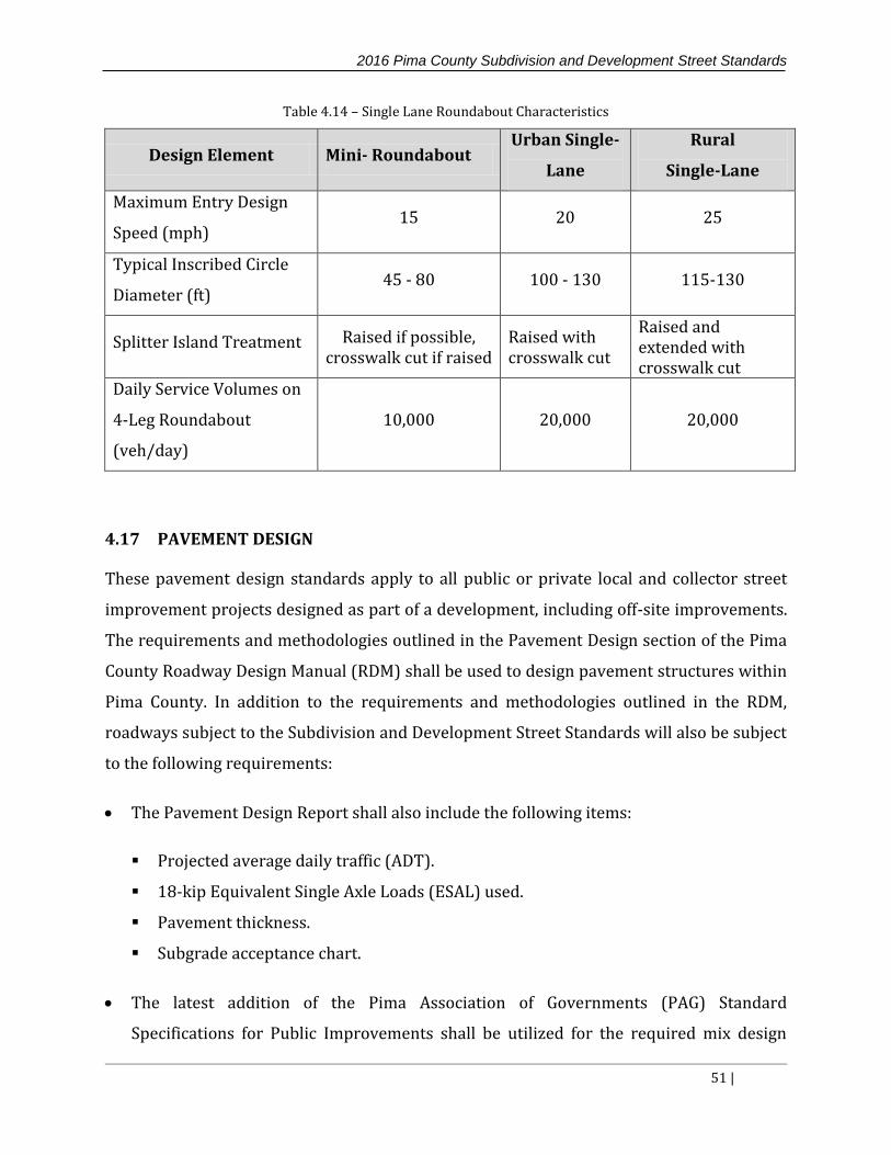
2016 Pima County Subdivision and Development Street Standards
51 |
Table 4.14 – Single Lane Roundabout Characteristics
Design Element Mini- Roundabout Urban Single-
Lane
Rural
Single-Lane
Maximum Entry Design
Speed (mph) 15 20 25
Typical Inscribed Circle
Diameter (ft) 45 - 80 100 - 130 115-130
Splitter Island Treatment Raised if possible, crosswalk cut if raised
Raised with crosswalk cut
Raised and extended with crosswalk cut
Daily Service Volumes on
4-Leg Roundabout
(veh/day)
10,000 20,000 20,000
4.17 PAVEMENT DESIGN
These pavement design standards apply to all public or private local and collector street
improvement projects designed as part of a development, including off-site improvements.
The requirements and methodologies outlined in the Pavement Design section of the Pima
County Roadway Design Manual (RDM) shall be used to design pavement structures within
Pima County. In addition to the requirements and methodologies outlined in the RDM,
roadways subject to the Subdivision and Development Street Standards will also be subject
to the following requirements:
The Pavement Design Report shall also include the following items:
Projected average daily traffic (ADT).
18-kip Equivalent Single Axle Loads (ESAL) used.
Pavement thickness.
Subgrade acceptance chart.
The latest addition of the Pima Association of Governments (PAG) Standard
Specifications for Public Improvements shall be utilized for the required mix design

2016 Pima County Subdivision and Development Street Standards
52 |
properties. All of these standard properties apply as stated with the exception of those
listed below:
Effective air voids shall be 3.5% +-0.2% for local streets and residential collectors
Minimum voids in the mineral aggregate (VMA) shall be 16.0%
Reclaimed asphalt pavement (RAP) is prohibited in local and residential collector
street mix design
Minimum compaction of asphaltic concrete (AC) shall be 96%
Based on the 20 year projected ADT, the following ESAL’s will be accepted for pavement
design:
Table 4.15 Accepted ESAL’s for Pavement Design
20 year ADT ESAL*
<500 40,000
500-1000 70,000
1000-1500 100,000
1500-2500 150,000
*100,000 ESALs are required for cul-de-sacs
When the projected 20 year ADT exceeds 2500, or when the engineer desires to
calculate their own ESAL’s, complete calculations, including a breakdown of the traffic
by vehicle type, shall be included in the pavement design report. The ESAL calculations
shall be based on the 20-year design period
The minimum weighted structural numbers (SN) and pavement sections by roadway
classification are presented in the RDM and, for cul-de-sacs, in Table 4.16.

2016 Pima County Subdivision and Development Street Standards
53 |
Table 4.16 Minimum Weighted Structural Numbers and Pavement Sections
Street Classification Minimum
SN
Minimum
AC
Minimum
AB
Cul-de-Sac-Local Streets 1.75 3.0” 4.0”
Roller compacted concrete pavement may be used on local streets (minimum 5 inch
thickness). No grinding or grooving is necessary if the placed finish meets the
coefficient of friction requirements for 25 mph as noted in Table 4.8. If roller compacted
concrete is utilized, a geotechnical report is required to provide the specifications and
acceptance criteria that is not part of Pima County standard specifications.
When existing streets are widened, the new pavement section shall either match the
existing pavement section or meet the applicable minimum thickness as required in the
RDM and Table 4.16 (for Cul-de-Sacs), whichever is greater.
When a street is widened, the complete cross section will be subject to pavement
replacement and/or surface treatment in accordance with the guidance offered in the
Pavement Replacement Standard Details found in the Pima County Procedures for the
Issuance of Right-of-Way Permits and Regulations of Work Under Permit
When through streets are designed which may ultimately connect to future
developments, pavement design and ESAL calculations shall accommodate future wheel
loads to account for all future loading.
4.18 DRAINAGE
Roadways are frequently subjected to flooding either by runoff transported across the
street, at drainage crossings or conveyed as shallow street flow. The following standards
have been developed to reduce the hazards associated with storm runoff along or across a
roadway. The goal of drainage design is to mitigate the effects of the impermeable surfaces
so that flows at the project limits are maintained at pre-development rates. Field and
topographic conditions should be considered in conjunction with these standards, and
engineering judgment should be exercised in all cases to minimize adverse effects to
adjoining property and to the right-of-way while maintaining traffic safety.

2016 Pima County Subdivision and Development Street Standards
54 |
A drainage report shall be prepared by a registered Professional Engineer and shall
follow the provisions of this chapter and the requirements of the Pima County Regional
Flood Control District website.
All proposed drainage improvements must conform to the requirements of the Federal
Emergency Management Agency (FEMA), Pima County Title 16, Pima County Drainage
and Channel Design Standards for Local Drainage9, and the Design Standards for
Stormwater Detention and Retention54 in Pima County.
STREET DRAINAGE
The provisions made in regards to drainage along streets are discussed below and
summarized in Table 4.19 – Design Criteria for Longitudinal Street Drainage.
Street flows shall not exceed 100 cfs or 1 foot in depth during the 100-year storm.
The 100-year discharge outside of curbs must be contained within the right-of-way and
cannot exceed 3 feet per second in velocity unless erosion mitigation is provided.
On collector streets, except where at-grade crossings are approved in rural
subdivisions, a minimum 10-foot pavement width must be kept clear of flowing or
ponded water in each direction of travel during the 10-year storm. Bypass gutter flows
from intersecting streets shall be reduced as necessary to meet this requirement within
intersections.
On curbed streets, the runoff from a 10-year storm must be contained between the
curbs of the street, except for roadside stormwater harvesting areas.
Should the 10-year discharge water surface elevation exceed the top of the curb, storm
drains or other treatments shall be provided to keep water from overtopping the curbs.
The minimum pipe size for storm drains shall be 18 inches for laterals and 24 inches for
mains. Storm drains are enclosed drain systems as opposed to culverts which have
separate sizing and material requirements.

2016 Pima County Subdivision and Development Street Standards
55 |
Table 4.19. Design Criteria for Longitudinal Street Drainage
Parameter Design
Standard
Maximum street runoff (cfs) 100
10-year storm containment – local streets Between Curbs
10-year storm – minimum width clear of water
(collectors)
10 ft per
direction
100-year storm containment Within R/W
Minimum storm drainpipe diameter (in)
lateral/main 18/24
Drainage conveyed within the street shall only be discharged from the street right-of-
way into common areas or privately maintained drainage easements (does not apply to
non-regulatory flows on uncurbed streets).
A drainage easement will be required whenever any natural watercourse has been
altered to such a degree as to need a defined or constructed channel, or periodic
maintenance.
Public easements beyond the right-of-way limits shall be granted to Pima County where
it is necessary to gain access to protect or maintain drainage features within the public
right-of-way.
CURB OPENINGS
Curb openings and curb depressions used for drainage shall have a maximum opening
of 10 feet (excluding transitions) and shall be fitted with outlet aprons located within
the right-of-way. The curb elevation must transition from the normal reveal to the level
of the opening at a slope of 12:1 in instances where sidewalk is behind curb (see Detail
17 - Curb Opening Detail).
If erosion protection extends outside of the right-of-way, a drainage easement shall be
provided.

2016 Pima County Subdivision and Development Street Standards
56 |
Curb openings and curb depressions must be spaced a minimum of 150 feet (from
centerline to centerline) unless scuppers are provided.
Curb openings and drainage inlets shall be fitted with appropriate barricades to prevent
vehicular access. Table 4.20 presents the design standards for curb openings.
Should the design require greater conveyance than can be provided by curb openings,
then scuppers, catch basins or other drainage structures must be used.
Table 4.20 Design Standards for Curb Openings
Parameter Design
Standard
Maximum length (ft) 10
Curb transition slope 12:1
Minimum spacing (ft) 150
CURB SCUPPERS
Scuppers are structures used to drain flow under a sidewalk, generally between a paved
area and a drainageway. Scuppers must be designed to accommodate the 10-year storm
without overtopping of the curbs. The PAG Standard Details 205 and 205.5 provide design
alternatives for sidewalk scuppers.
CATCH BASINS
Catch basins are structures used to drain the pavement into storm drain systems. Catch
basins must be designed to accommodate the 10-year storm without overtopping of the
curbs. In areas where pedestrian or bicycle traffic is expected, the design, installation and
location of catch basins should be done in such a way as to minimize potential hazards to
pedestrians and bicyclists.

2016 Pima County Subdivision and Development Street Standards
57 |
STORMWATER HARVESTING WITHIN THE RIGHT-OF-WAY
Stormwater harvesting is not required by these standards, however, the designer is
encouraged to incorporate stormwater harvesting as part of a Complete Streets design
approach to enhance the pedestrian experience by sustaining canopy trees and vegetation.
Stormwater harvesting features, if designed correctly, will reduce runoff peaks and
volumes and can be used to satisfy the first flush retention requirement. Stormwater
harvesting may also offset additional grading required for stormwater detention basins.
Guidance on stormwater harvesting features can be found in the Design Standards for
Stormwater Detention and Retention57 and the Low-Impact Development and Green
Infrastructure Guidance Manual56.
Stormwater harvesting features in the right-of-way are limited to basins in the median or
roadside that do not retain more than nine inches of water (first flush retention). These
basins must be designed such that the flows do not cause flooding onto the roadway.
In order to ensure adequate sight visibility, roadside stormwater harvesting basins should
be located at least twenty feet from street intersections and at least five feet from driveway
entrances. In addition, roadside stormwater harvesting basins should be setback at least
one foot from sidewalks and six inches from the edge of curb where there is no on-street
parking and two feet from the edge of curb where there is on street parking.
In areas where stormwater harvesting is designed to be in the curbway, the sidewalk may
be narrowed to 4 feet to provide a greater curbway width, provided that ADA requirements
are met. Pima County encourages wider right-of-way for stormwater harvesting and
vegetation and under these circumstances; the curbway width is not limited.
When stormwater harvesting features are implemented in the right-of-way, vertical curb
should be designed with curb core and curb cuts for stormwater features. Medians and
traffic circles designed for stormwater harvesting may use header curb per PAG Standard
Detail 213 to maximize the roadway runoff into basins.
When used for stormwater harvesting, curb cuts shall meet the following criteria:

2016 Pima County Subdivision and Development Street Standards
58 |
Curb cuts shall be separated from driveway aprons and other curb openings by a
minimum distance of 10 feet
Curb cuts shall be located a minimum of 20 feet from an end of a curb return (corner)
Curb cuts shall be a maximum of 2 feet in width with 45-degree sloped sides
ROADSIDE CHANNELS AND DITCHES
Channels or ditches parallel to the roadway shall be laid out to be either completely
within or outside of the public right-of-way for the purpose of defining maintenance
responsibilities and shall not straddle the right-of-way.
Ditches or channels shall not be constructed within the right-of-way unless:
The design flow can be handled by the channel or ditch without interfering with the
reasonable operation of the roadway, and
A ditch or channel that is parallel to the road is to be configured in a manner that is
consistent with the cross-section configuration and operational and maintenance
needs of that roadway. This includes the potential uses of the roadside by
pedestrians, equestrians, bicycles, vehicles (on and off road types), utilities, traffic
control devices or other applicable and relevant roadside features. The depth,
foreslope, backslope, profile and hydraulic operation provided shall provide
consideration of all these applicable uses in a manner that is reasonable and has
been defined by practice and reasonable references (e.g. AASHTO Roadside Design
Guide28).
Channel design should consider two elements:
Hydraulic design: To ensure that channels are able to convey the design runoff, they
shall be designed in conformance with the Pima County Drainage and Channel Design
Standards for Local Drainage.
Effect on roadside: Channels shall be designed as to minimize their impact on the
roadside and shall not be constructed within the shoulder area of any roadway.

2016 Pima County Subdivision and Development Street Standards
59 |
Drainage swales within the right-of-way that carry roadway runoff shall only be acceptable
where 100-year velocities are less than 3 feet per second (or where appropriate protection
is provided), and where driveway access is restricted or controlled to prevent ponding,
diversion of flow or other conflicts.
A drainage easement will be required whenever any natural watercourse has been altered
to such a degree as to need a constructed channel cross-section and periodic maintenance;
or if through development, storm runoff is concentrated to such a degree as to require a
defined channel. Public easements beyond the right-of-way limits shall be granted to Pima
County where it is necessary to gain access to protect or maintain drainage features within
the public right-of-way.
CROSS DRAINAGE
Storm drainage across the roadway must be handled by culverts, at-grade crossings or by
culvert and at-grade crossing combinations, depending on the design period and peak
discharge. The specific design criteria for those treatments are discussed in this section.
Regardless of the cross drainage treatment used, emergency vehicles and other vehicles
must be able to safely access the subdivision in flooding situations. Therefore, at least one
paved, permanent all-weather access shall be provided to each lot. The maximum flow
depth over the roadway for all-weather access shall be as defined in the Pima County Code,
Chapter 16-36.
The Pima County Code1 Title 16 prohibits improvements which are not compatible with
upstream and downstream drainage conditions and which have an adverse impact on
surrounding properties. Flood limits, depths, and velocities shall be kept unchanged where
flows impact adjacent property, unless an improved channel or other measures to prevent
adverse impacts are provided. Common areas or privately maintained drainage easements
shall be provided within the subdivision for cross-drainage. In addition, public easements
beyond the right-of-way limits shall be granted to Pima County where it is necessary to
gain access to protect or maintain drainage features within the public right-of-way.

2016 Pima County Subdivision and Development Street Standards
60 |
When sheet flooding conditions impact a development and roadways are proposed
perpendicular to flow, at-grade design is preferred to limit water surface elevation
increases beyond the right-of-way, to minimize obstructions to flow, to avoid
sedimentation issues associated with collector channels and to minimize off-site
construction of training dikes.
CULVERTS
Culvert structures shall be required at all drainage crossings, except where at-grade
crossings are provided in rural residential subdivisions, when flows are conveyed within
natural channels and overbank areas or within constructed channels.
Public maintenance and access easements shall be granted for maintenance of collector
channels or dikes outside of the public right-of-way.
In local streets, culverts shall be designed to convey at least the 10-year flow under the
roadway, unless at-grade crossings are approved for sheet flooding conditions. Culverts
across residential collectors shall convey at least the 25-year flow under the roadway.
Culverts across major collectors shall convey at least the 50-year flow under the roadway
or, if possible, the 100-year flow under the roadway. Whenever a culvert is designed for
less than the 100-year event, the excess flow during that event shall be contained within a
dip with a flow depth of less than 1 foot in the 100-year event. If the roadway is all-
weather access, the flow depth shall not exceed the requirements defined in the Pima
County Code1 Title 16. Table 4.21 summarizes the minimum design flow requirements for
culverts.

2016 Pima County Subdivision and Development Street Standards
61 |
Table 4.21 Minimum design flow for culverts
Street Class Design Standard
Local Street Q10 under roadway, Q100 less than 1 foot* in depth with dip
Residential
Collector Q25 under roadway, Q100 less than 1 foot* in depth with dip
Major Collector Q50 (Q100 if possible) under roadway, Q100 contained within dip*
*If roadway is an all-weather access, the maximum flow depth shall be in compliance with Pima County Code1
Title 16
In addition to the specific requirements described above, culverts constructed for
subdivisions must meet the following criteria:
Pipe culverts shall have a minimum diameter of 24 inches. 18 inch pipes may be used if
needed to meet clearances which would otherwise require significant site engineering
to accommodate.
Reinforced Concrete Pipes (RCP), Corrugated Metal Pipes (CMP), and Spiral Rib Pipe
(SRP) are acceptable for pipe culverts. Pipes made of other materials will require
approval from Pima County. HDPE pipe is approved for use in enclosed storm drain
systems only.
Headwalls or engineered slope protection shall be required at inlets for pipes greater
than 30 inches in diameter, multiple pipe culverts and Reinforced Concrete Box
Culverts (RCBC). For channels in supercritical flow, wingwalls and headwalls shall be
required.
Reinforced Concrete Box Culverts (RCBC) in right-of-way shall be at least 4 feet in
height and shall be structurally designed according to Arizona Department of
Transportation’s (ADOT) Structure Detail Drawings – Bridge Group40 or by a licensed
Arizona registered engineer.

2016 Pima County Subdivision and Development Street Standards
62 |
Erosion protection must be provided at the culvert outlets according to the
requirements of Drainage and Channel Design Standards for Local Drainage or City of
Tucson Standards Manual for Drainage Design and Floodplain Management. If the length
of protection needed to reduce flow velocity becomes excessive, another form of
protection should be used.
The velocity at the culvert outlet shall be greater than 3 feet per second to reduce
culvert maintenance needs.
All culverts with headwalls shall extend at least the distances outlined in Section 3.6 –
Horizontal Clearance to Obstructions to protect errant vehicles and pedestrians. Where
culverts cannot be extended for this distance, guardrails or other suitable traffic
barriers must be used as discussed in Section 3.7 – Traffic Barriers.
AT-GRADE CROSSINGS FOR URBAN RESIDENTIAL, COMMERCIAL AND INDUSTRIAL
SUBDIVISIONS
At-grade crossings shall only be used to supplement culverts during certain rainfall events
(see Section 4.18 - Culverts), unless at-grade crossings have been approved for sheet
flooding conditions crossing local streets.
Post barricades shall be placed at at-grade crossings exceeding 50 cfs.
At-grade crossings in which the transverse flow during the 100-year event is less than
or equal to 50 cfs, shall at least be fitted with 6-inch by 12-inch concrete headers.
If the 100-year flow ranges from 50 to 500 cfs, cut-off walls must be constructed. Cut-off
walls shall be designed 1 foot deeper than the scour determined by the use of the
approved general and local scour equations or 70% of the maximum depth of scour.
However, in no case shall the cut-off wall depth be less than 2 feet upstream and 3 feet
downstream.
Sliding and overturning moments may need to be analyzed for at-grade crossings
protected by cut-off walls deeper than 6 feet.

2016 Pima County Subdivision and Development Street Standards
63 |
Concrete headers and cut-off walls must extend to the limits of the developed 100-year
flow width along the pavement edge.
Cut-off walls shall be placed at least 4 feet from the upstream and downstream edge of
pavement lines. The pavement shall be widened to the upstream and downstream cut-
off walls.
At-grade crossings should be built at a minimum 4% cross slope to reduce deposition of
sediment. A reduced cross slope may be approved if engineering justification is
provided. This 4% grade shall be produced by supplying the vertical rise on the
upstream side of the dip section with the downstream side meeting the existing grade.
If controls for traffic safety, or accommodation of sheet flows, dictate a reduced cross
slope, sediment reduction may be accomplished by installation of a sediment trap or
other means approved by Pima County.
The flow rate of the 100-year event for at-grade crossings shall not exceed 500 cfs.
AT-GRADE CROSSINGS FOR RURAL RESIDENTIAL SUBDIVISIONS
At-grade crossings are acceptable in rural residential subdivisions, provided that the
100-year flow traversing the roadway is less than 500 cfs and all-weather criteria are
met.
If the 100-year peak discharge exceeds 500 cfs over the entire roadway length due to
sheet flooding conditions, and the 100-year flow depth is less than one foot, at grade
crossings are acceptable.
If the 100-year flow ranges from 50 to 500 cfs, cut-off walls shall be installed to
maintain the integrity of the roadway pavement.
Cut-off walls shall be designed 1 foot deeper than the scour determined by the use of
the approved general and local scour equations or 70% of the maximum depth of scour.

2016 Pima County Subdivision and Development Street Standards
64 |
In no case shall the cut-off wall depth be less than 2 feet upstream and 3 feet
downstream.
Sliding and overturning moments may need to be analyzed for at-grade crossings
protected by cut-off walls deeper than 6 feet.
Cut-off walls shall be placed at least 4 feet from the upstream and downstream edge of
pavement lines. The pavement shall be widened to the upstream and downstream cut-
off walls.
Concrete headers and cut-off walls must extend the developed 100-year flow width.
If the flow depth of the 100-year event will cross the road at a depth greater than one
foot, a culvert or a culvert dip section combination shall be used to guarantee that the
drainage over the roadway meets all-weather access criteria.
The design thresholds for dip sections are illustrated in Table 4.22.
Table 4.22 Design thresholds for dip sections
Street Class Design Standard
≤ 50 cfs Concrete Headers
50-500 cfs Cut-off walls
≥ 500 cfs Culvert or Culvert + dip section
At-grade crossings should be built at a minimum 4% cross slope to reduce deposition of
sediment. This 4% grade shall be produced by supplying the vertical rise on the
upstream side of the dip section with the downstream side meting the existing grade.
If controls for traffic safety, or accommodation of sheet flooding conditions dictate a
reduced cross slope, sediment reduction may be accomplished by installation of a
sediment trap or other means approved by Pima County.

2016 Pima County Subdivision and Development Street Standards
65 |
5 COMMERCIAL AND INDUSTRIAL SITE DESIGN
The design standards for commercial and industrial sites focus on driveway location and
design and onsite circulation and parking. For commercial/industrial projects that are
required to make improvements to adjacent streets, the off-site improvements shall adhere
to the requirements of chapters 3 and 4 of this manual or the Roadway Design Manual, as
appropriate.
5.1 DRIVEWAY LOCATION
Driveways should be located so that they have a minimum impact on the traffic flow and
safety of the street. All driveways are subject to the following requirements.
The distance between adjacent driveways shall meet the minimum spacing
requirements in Table 5.1 and be measured from nearest driveway edge to nearest
driveway edge as depicted in Figure 5.1. Pima County may request increased
driveway spacing in rural areas, or when warranted by field conditions such as
significant weaving or insufficient left turn queue storage during the peak period.
On undivided roadways, the spacing requirements apply to driveways on both sides
of the street.
Corner clearance is the distance between a driveway and the adjacent street
intersection. The minimum allowable corner clearance is presented in Table 5.1.
The driveway to road spacing shall be measured from nearest driveway edge to
nearest road edge as depicted in Figure 5.2.
Driveways shall not be located within the functional limits of the intersection unless
approved by Pima County. The functional limits are defined as the area between the
near curb line of the cross street and the beginning of tapers for right- and left-turn
lanes.
Pima County encourages shared access.

2016 Pima County Subdivision and Development Street Standards
66 |
Table 5.1 Driveway Spacing
Posted Speed on Adjacent
Street (mph)
Minimum Driveway
Spacing* (ft)
Minimum Corner
Clearance (ft)
25 105 150
30 125 150
35 150 150
40 185 185
45 230 230
50 275 275
Figure 5.1 Driveway Spacing Measurement
The maximum number of driveways for any lot shall be limited to two per three
hundred feet of frontage along any single street.
Driveways near median openings should be centered with the median opening or be a
minimum of 100 feet from the center of the median opening.

2016 Pima County Subdivision and Development Street Standards
67 |
If return radii are used for the driveway, the returns shall be located within the
extension of the property line, to ensure that they do not interfere with the adjacent
property.
Figure 5.2 Driveway to Road Spacing Measurement
5.2 DRIVEWAY DESIGN
Driveway Aprons and Return Radius
On streets with vertical curbs, the use of driveway aprons with curb cuts is preferred to
the use of return radii. The design of the driveway apron shall be in accordance with
PAG Standard Detail 206.
Return radii may be allowed on curbed roadways (See Detail 16) instead of standard
curb cuts when one or more of the following conditions occur:
The projected Average Daily Traffic (ADT) of the driveway exceeds one hundred
vehicles. The projected ADT must be calculated using the trip generation rates
published in the latest edition of Trip Generation5 from the Institute of
Transportation Engineers (ITE).
The posted speed limit on the roadway is greater than 45 mph.
The driveway is served by a specific median opening with left turn storage.

2016 Pima County Subdivision and Development Street Standards
68 |
The type of development, the amount of truck traffic, or the prevailing travel speeds,
make curb cuts unsafe or undesirable.
Driveways on rural, uncurbed streets shall have 6-inch by 12-inch concrete headers
placed adjacent to the pavement on all returns per PAG Standard Detail 213.
Driveway return radii larger than 40 feet shall not be used without approval from Pima
County as this may lead to unsafe conditions for pedestrians and bicyclists.
The minimum driveway return radii by type of roadway are summarized in Table 5.3.
Table 5.3 Minimum Return Radius
Functional Classification Minimum Return Radius*
Local Street 25
Collector or Arterial Street 30
*The radius must be large enough accommodate the design vehicle
Width
For two-lane commercial driveways the minimum width shall be 24 feet and the
maximum width shall be 30 feet.
For a three lane driveway that is striped for one lane in and two lanes out without a
median, the maximum width is 36 feet.
For driveways greater than 36 feet in width, a median is required. Where a median
island is provided to separate inbound and outbound traffic, it shall be not less than 6
feet or more than 16 feet wide.
Each side of a median-divided driveway shall be at least 16 feet wide to ensure
accessibility of emergency vehicles.

2016 Pima County Subdivision and Development Street Standards
69 |
Grade
The vertical profile of a driveway should allow a smooth transition to and from the
roadway. A minimum 20 foot long landing area of no greater than 3% slope shall be
provided on roadway approaches. The maximum allowable grade for commercial and
industrial driveways shall be 6%. (See Detail 16)
Angle of Connection
Connection angles at the intersection of driveways with public roadways should be as close
to 90 degrees as practicable, but no less than 70 degrees.
Throat Length
The throat length is the distance between the edge of the pavement of the adjacent street
and the end of the driveway inside the development as shown in figure 5.3.
Where a driveway median is provided equal to the throat length, the throat length
requirement only applies to inbound traffic.
Figure 5.3 Driveway Throat Length
Source: Florida Department of Transportation
When a development requires a Traffic Impact Study (TIS), a queuing analysis should
be performed as part of the TIS to determine expected queue lengths. The throat length
should be designed to accommodate the calculated queues.

2016 Pima County Subdivision and Development Street Standards
70 |
When there is no queuing analysis, the minimum driveway throat length is 50 feet.
Single lot commercial developments can utilize a 30 foot throat length subject to the
following:
Left turns are not allowed into the development.
A right-turn lane into the development is provided.
The parking configuration does not allow for backing vehicles to conflict with
entering traffic.
5.3 DESIGN OF PARKING AREAS
Parking Lot Layout
All parking spaces and parking aisles (access lanes) shall be designed in conformance
with the parking area dimensions in Table 5.4.
The minimum dimensions for standard parking spaces shall be 9 feet by 20 feet.
Handicapped accessible spaces shall be a minimum of 13 feet by 20 feet. However, two
accessible parking spaces may share a common access aisle as provided in Figure 5.4.
The orientation of Parking Area Access Lanes (PAALs) shall be perpendicular to the
building faces to accommodate convenient pedestrian movements.
Passenger drop-off points, separated from street traffic and access lanes are to be
provided in conjunction with the following uses: Hotels, motels, hospitals, clinics,
schools with fifty or more pupils, day care centers, religious facilities with one hundred
or more seats, and recreational facilities.
All parking lots shall provide unrestricted access for emergency and service vehicles.
The designer shall utilize geometric characteristics of the SU-30 design vehicle with
forty-two-foot turning radius.
Parking spaces in paved parking areas shall be permanently marked with striping in
accordance with the Manual on Uniform Traffic Control Devices. Striping shall be, white

2016 Pima County Subdivision and Development Street Standards
71 |
paint or plastic, and extend for a minimum of ten feet for interior lines. End lines shall
extend the full length of the space.
Parking areas and spaces shall be provided with bumper barriers, wheel stops or wheel
stop curbing, designed to prevent parked vehicles from extending beyond the property
lines, damaging adjacent landscaping, walls or buildings, or overhanging pedestrian
walkways.
Figure 5.4 Handicapped Parking with Shared Aisle

2016 Pima County Subdivision and Development Street Standards
72 |
Table 5.4 Parking Area Dimensions and Guidelines
Parking areas shall not be designed to require or encourage vehicles to back into a
street, pedestrian access way, or alley in order to leave the lot or maneuver out of a
parking space.
ELEMENTS
A Parking Angle
B Space Width
C Space Depth
D Aisle Width
E Curb Length
F Curb to Curb Bay Width
G Space Center to Center Width
A B C D E F G
0O 9.0 9.0 12.0 23.0 30.0 -
9.5 9.5 12.0 23.0 31.0 -
10.0 10.0 12.0 23.0 32.0 -
20O 9.0 15.3 12.0 26.4 42.6 34.1
9.5 15.7 12.0 28.0 43.4 34.5
10.0 16.3 12.0 29.6 44.6 35.2
30O 9.0 17.8 12.0 18.0 47.6 39.8
9.5 18.2 12.0 19.0 48.4 40.2
10.0 18.6 12.0 20.0 49.2 40.5
45O 9.0 20.4 13.0 12.7 53.8 48.0
9.5 20.6 13.0 13.4 54.2 48.0
10.0 21.2 13.0 14.1 55.4 48.3
60O 9.0 21.9 18.0 10.4 61.8 57.5
9.5 22.1 18.0 11.0 62.2 57.7
10.0 22.5 18.0 11.5 63.0 58.0
70O 9.0 22.0 19.0 9.5 63.0 60.3
9.5 22.2 19.0 10.1 63.4 60.3
10.0 22.3 19.0 10.5 63.6 60.3
80O 9.0 21.5 24.0 9.6 67.0 -
9.5 21.5 24.0 10.1 67.0 -
10.0 21.5 24.0 10.6 67.0 -
90O 9.0 20.0 24.0 9.0 64.0 -
9.5 20.0 24.0 9.5 64.0 -
10.0 20.0 24.0 10.0 64.0 -
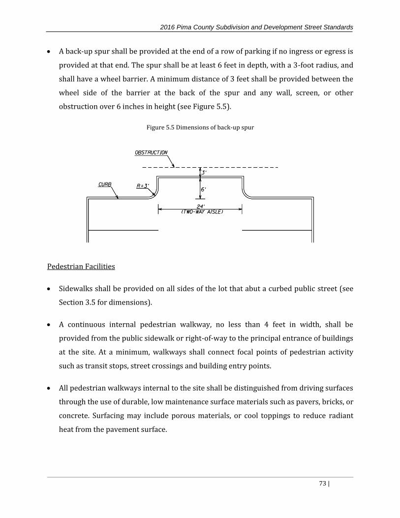
2016 Pima County Subdivision and Development Street Standards
73 |
A back-up spur shall be provided at the end of a row of parking if no ingress or egress is
provided at that end. The spur shall be at least 6 feet in depth, with a 3-foot radius, and
shall have a wheel barrier. A minimum distance of 3 feet shall be provided between the
wheel side of the barrier at the back of the spur and any wall, screen, or other
obstruction over 6 inches in height (see Figure 5.5).
Figure 5.5 Dimensions of back-up spur
Pedestrian Facilities
Sidewalks shall be provided on all sides of the lot that abut a curbed public street (see
Section 3.5 for dimensions).
A continuous internal pedestrian walkway, no less than 4 feet in width, shall be
provided from the public sidewalk or right-of-way to the principal entrance of buildings
at the site. At a minimum, walkways shall connect focal points of pedestrian activity
such as transit stops, street crossings and building entry points.
All pedestrian walkways internal to the site shall be distinguished from driving surfaces
through the use of durable, low maintenance surface materials such as pavers, bricks, or
concrete. Surfacing may include porous materials, or cool toppings to reduce radiant
heat from the pavement surface.

2016 Pima County Subdivision and Development Street Standards
74 |
Bicycle Facilities
Bicycle parking spaces shall be provided as specified in Chapter 18.75 of the Pima
County Code1.
When bicycle racks are installed, they must adhere to the following guidelines.
Bicycle racks must be securely anchored to the ground, floor, wall or ceiling.
Bicycle racks must be designed so that the bicycle frame and one wheel can be locked to
the rack with a high security, U-shaped lock if both wheels are left on the bicycle
Bicycle racks must be designed such that a bicycle six feet long can be securely held
with its frame supported so the bicycle cannot be pushed or fall in a manner that will
damage the wheels or components
A single bicycle rack must be designed and located to accommodate two bicycles
Bicycle racks must not have sharp edges that can be hazardous to pedestrians,
particularly individuals with visual disabilities.
A bicycle rack must be a minimum of two and one half feet from a wall or other
obstruction.
An access aisle at least five feet wide must be provided between two rows of bicycle
parking.
Examples of acceptable bicycle rack designs are shown in Figure 5.6

2016 Pima County Subdivision and Development Street Standards
75 |
Figure 5.6 Bicycle Rack Design Examples
Source: City of Tucson Land Use Code Section 3.3.9.5.A
PARKING LOT DRAINAGE
Parking may be permitted in the flood plains of regulated watercourses, washes and
detention/retention basins, provided that the maximum depth of flooding does not
exceed 1 foot during the 100-year event, and the velocity is below 2 ft/s. Such parking
lots shall have a prominent sign posted at the entrance to the parking area that contains
the information that the parking lot is subject to periodic flooding of depths up to 1 foot.
2016 Pima County Subdivision and Development Street Standards
76 |
Drainage of parking lots can be accomplished by means of curb openings, curb cores,
scuppers, catch basins and storm drain systems in general as discussed in Section 4.18.
Inverted roadway crowns or concrete valley gutters are allowed in parking aisles or
between stormwater harvesting basins. The minimum longitudinal slope permitted
within parking areas is 0.5%.
PARKING LOT PAVEMENT
In order to control particulate matter, all parking areas shall be paved. Parking areas
with up to 10 spaces can use a double chip seal or brick pavers as dust control
treatments, provided that there is no significant truck traffic.
For parking areas with ten or more spaces, a minimum Structural Number (SN) of 1.35
shall be required. This structural number can be obtained by using two inches of
asphaltic concrete (AC) on four inches of compacted aggregate base (AB). Depending
upon the expected traffic conditions, Pima County may request a pavement design
report prepared by a Registered Professional Engineer, to determine if a pavement
section with a greater SN is needed.
Other types of surfacing, including permeable pavements, may be used with the
concurrence of the County provided that the pavement structural requirements are met
and a Registered Professional Engineer certifies the design.
Paving may not be required in certain vehicle-accessible areas such as contractor’s
yards or storage areas that are access controlled. However, those areas shall still use
surface treatments such as gravel or decomposed granite to ensure dust control.
DRIVE-THRU QUEUING
The minimum storage requirements for the most common types of drive-thru facilities are
presented in Table 5.5. The storage lengths shown in Table 5.5 shall be accomplished
without interfering with the through streets or the parking area access lanes. For drive-
thru facilities not included in Table 5.5, or facilities known or expected to have higher than

2016 Pima County Subdivision and Development Street Standards
77 |
typical trip generation, the storage length shall be determined by an engineered queuing
analysis.
Table 5.5 Minimum required drive-thru storage per lane
Source: Queuing Areas for Drive-Thru Facilities, ITE Journal, May 199538
Drive-Thru Facility
Required
Storage per
Lane (veh)
Required
Storage per
Lane (ft)
Fast-Food 9 180
Bank 7 140
Car Wash (self-service) 2 40
Day Care 9 180
Dry Cleaner 2 40

2016 Pima County Subdivision and Development Street Standards
78 |
6 ADMINISTRATION OF THE STANDARDS
This section addresses the procedures that shall be followed to manage and implement the
standards and requirements in this manual. Responsibility to administer, coordinate and
enforce the provisions and standards in this manual shall be as follows:
The County Engineer, or his/her designee shall have responsibility over all elements
within the present or future street right-of-way, whether public or private, including
areas having a direct safety, capacity or maintenance impact thereon
The Chief Building Official, or his/her designee shall have responsibility over
development areas outside street right-of-way
The due-process appeal route regarding interpretation or request for modifications to
these standards shall be as follows:
Elements within direct impact to present or future right-of-way: staff interpretation,
SDSS Modification Committee, County Engineer
Elements within development areas other than right-of-way: staff interpretation, SDSS
Modification Committee, Chief Building Official, Board of Adjustment, Superior Court
6.1 STAFF INTERPRETATION AND MODIFICATIONS
County staff are empowered to interpret and approve minor modifications to these
standards in alignment with the principles reflected herein or through referenced
nationally recognized standards or methodologies.
6.2 SDSS MODIFICATION COMMITTEE
The County Engineer shall appoint and coordinate the activities of a subdivision and
development street standards committee, here-in-after referred to as the “Committee”.
The appointed Committee shall have the following characteristics:
Number of members: The Committee shall be composed of six persons.
Affiliation and qualifications of members: The affiliation of the members shall be as follows:

2016 Pima County Subdivision and Development Street Standards
79 |
Three members shall be from the Pima County Department of Transportation.
Three members shall be employed in the private sector.
Four of the members shall be registered Professional Engineers in the State of Arizona.
All members shall have knowledge and experience in subdivision design and have a
good understanding of the development process.
Appointing Authority: All Committee appointments shall be made by the County Engineer.
The County Engineer may also approve an alternate for each member that may serve in the
event of an absence.
Term: Committee members serve at the pleasure of the County Engineer.
Transaction of Business:
Procedures: The Committee may adopt policies and standard operating procedures,
subject to the approval of the County Engineer, to assure the efficient, predictable, fair
and balanced administration of the Committee’s work.
Meeting frequency: The Committee shall meet as necessary to conduct the Committee’s
business.
Quorum: The Committee shall be considered to be duly assembled at meetings where at
least three members or alternates are present If fewer than three members or
alternates are present the meeting shall be re-scheduled.
Voting: Each member of the Committee shall have one vote in all decisions requiring a
vote. A request to the committee for an interpretation or a modification requires a vote.
Minutes: A recording secretary shall prepare meeting minutes which shall include all
agenda and discussion items and all votes and consensus actions by the committee.
Minority opinions shall be included in the meeting minutes when requested by the
member(s) casting the minority vote(s).

2016 Pima County Subdivision and Development Street Standards
80 |
Responsibility: The Committee shall not approve or deny any request for modification or
interpretation, but shall only provide a recommendation for approval or denial to the
County Engineer or Chief Building Official.
6.3 MODIFICATIONS AND INTERPRETATIONS
If the designer believes that a provision of these standards is vague or unclear, a formal
interpretation may be requested from Pima County. In other cases, strict compliance with
these standards may not be feasible due to unusual site conditions. Pima County may grant
a modification of these standards if the following criteria are met:
The strict application of the provision(s) in question would create an extraordinary and
unnecessary hardship due to topographic or other pre-existing physical conditions of
the land. The hardship shall not arise from a condition created by an action of the
owner of the property.
The modification is consistent with the general intent and purpose of the standards and
the provision(s) from which the modification is requested..
The modification does not violate State law or other provisions of Pima County
ordinances or policies.
The modification will not cause injury to the rights of surrounding property owners and
residents.
The modification will not reduce traffic safety, capacity, functional utility of the street
system or negatively impact maintenance.
The modification makes a clear and definable contribution to Pima County’s economic
development priorities.
6.4 REQUESTS FOR MODIFICATIONS AND INTERPRETATIONS
Requests shall be submitted and processed per current procedures posted at the
Development Services website.

2016 Pima County Subdivision and Development Street Standards
81 |
6.5 COUNTY ENGINEER AND CHIEF BUILDING OFFICIAL ACTIONS ON
MODIFICATIONS AND INTERPRETATIONS REQUESTS
The County Engineer or Chief Building Official may seek the recommendation of the
Committee for interpretations and modifications of the standards in this manual.
Contingent on the above listed scope of responsibility, the County Engineer, Chief Building
Official or his/her designee may accept or reject the Committee’s recommendation and
provide the applicant a decision in writing three working days of the Committee meeting.
The request shall include the reason why the Committee’s decision is accepted or rejected.
Per statutory authority, the decision of the County Engineer over the street right-of-way is
final and cannot be appealed. However, if the applicant is not satisfied with the decision of
the Chief Building Official, the decision may be appealed to the County Board of Adjustment
by notifying the project Site Review Manager of the request within thirty calendar days of
the Committee decision. Appeals to the Board of Adjustment shall be scheduled within
three working days of request for the next available Board of Adjustment meeting date, in
accordance with County policy.
6.6 MODIFICATIONS TO THESE STANDARDS
Modifications to these standards which are identified as repeatedly approved through the
County modification process shall be incorporated into an appendix chapter upon approval
of the County Engineer or Chief Building Official, contingent on area of responsibility. Once
incorporated herein, these modifications, in accordance with the limitations attached
thereto, become part of the standards and may be used without invoking the modification
process.

2016 Pima County Subdivision and Development Street Standards
82 |
7 STANDARD DETAILS AND CROSS SECTIONS


105
8. APPENDIX
A-1 LEFT TURN LANE GUIDELINES9

106
A-2 RIGHT TURN LANE GUIDELINES FOR TWO-LANE ROADS9

107
A-3 RIGHT TURN LANE GUIDELINES FOR FOUR-LANE ROADS9

108
9. REFERENCES
1. American Association of State Highway and Transportation Officials. A Policy on Geometric Design of Highways and Streets, Washington D.C., 2011.
2. American Association of State Highway and Transportation Officials. Guide for the Planning, Design, and Operation of Pedestrian Facilities, Washington D.C., 2004.
3. American Association of State Highway and Transportation Officials. Highway
Safety Manual, Washington D.C., 2010.
4. American Association of State Highway and Transportation Officials. Roadside Design Guide, Washington D.C., 2011.
5. Arizona Department of Transportation. Materials Preliminary Engineering and Design Manual, Third Edition, Phoenix, 1989.
6. Arizona Department of Transportation. Policies, Guidelines and Procedures: Section 240 Traffic Impact Analyses, Phoenix, 2000.
7. Arizona Department of Transportation. Standard Drawings - Structures Section, Phoenix, 1992. 8. City of Tucson. Development Standards, Tucson, 2000. 9. City of Tucson. Transportation Access Management Guidelines, Tucson, 2011. 10. City of Tucson, Land Use Code Section 3.3.9.2., Tucson, 1995. 11. City of Tucson/Pima County. Outdoor Lighting Code, Tucson, 2012. 12. Federal Highway Administration. Pedestrian Safety Guide and Countermeasure
Selection System, http://www.pedbikesafe.org/PEDSAFE/. 13. Florida Department of Transportation. Site Impact Handbook, Tallahassee, 1997. 14. Florida Department of Transportation. Traffic Analysis Handbook, Tallahassee,
2014. 15. Institute of Transportation Engineers. Manual of Transportation Engineering Studies,
Second Edition, Washington D.C, 2010. 16. Institute of Transportation Engineers. School Site Planning, Design and
Transportation, Washington D.C, 2013. 17. Institute of Transportation Engineers. Traffic Calming Library,
http://www.ite.org/traffic/.

109
18. Institute of Transportation Engineers. Trip Generation Manual, Ninth Edition,
Washington D.C., 2012. 19. ITE Technical Council Committee 5d-10. ITE Journal: Queuing Areas for Drive-Thru
Facilities, Washington D.C., May 1995. 20. Kindler, C.E. et al. IHSDM Federal Highway Administration Report No. FHWA-RD-
02-045:Intersection Diagnostic Review Model, Washington D.C., 2003. 21. Koepke, Frank J. and Levinson, Herbert S. NCHRP Report 348: Access
Management Policies and Guidelines for Activity Centers, Transportation Research Board, Washington D.C., 1989.
22. Los Angeles County. Model Design Manual for Living Streets, Los Angeles, 2011. 23. Maricopa Association of Governments. Pedestrian Policies and Design Guidelines,
Maricopa County, 2005. 24. Maricopa Association of Governments. Uniform Standard Details for Public
Works Construction, 1998.
25. Maricopa County Department of Transportation. MCDOT Traffic Impact Procedures, 2000.
26. National Cooperative Highway Research Program, Report 659: Guide for the Geometric Design of Driveways, Washington D.C., 2010. 27. National Cooperative Highway Research Program. Report 672: Roundabouts: An
Informational Guide, Second Edition, 2010. 28. Pima Association of Governments. Regional Pedestrian Plan, Tucson, 2000. 29. Pima Association of Governments. Regional Plan for Bicycling, Tucson, 2000. 30. Pima Association of Governments, Standard Detail Drawings and Specifications,
Tucson. 31. Pima County, Design Standards for Stormwater Detention and Retention, Tucson,
2014. 32. Pima County. Eastern Pima County Trail System Master Plan, Tucson, 1996 33. Pima County, Low Impact Development and Green Infrastructure Guidance Manual,
Tucson, 2014. 34. Pima County. Pima County Code, Tucson

110
35. Pima County. Major Streets Plan, Tucson, 2015. 36. Pima County. Ordinance 2010-FC5:Floodplain Management Ordinance, Tucson,
2010. 37. Pima County. Regulated Riparian Habitat Mitigation Standards and Implementation
Guidelines, Tucson, 2001 38. Pima County Department of Transportation. Environmentally Sensitive Roadway
Design Guidelines, Tucson, 2002. 39. Pima County Department of Transportation. Pavement Marking Design Manual,
Tucson, 2002. 40. Pima County Department of Transportation. Roadway Design Manual, Tucson, 2013. 41. Pima County Department of Transportation. Signing Manual, Tucson, 2002. 42. Pima County Department of Transportation. Transit Guidelines for Roadway Design
and Construction, Tucson, 2009. 43. Pima County Regional Flood Control District. Drainage and Channel Design Standards
for Local Drainage, Tucson, 1984. 44. Smart Growth. Four Model Ordinances to Help Create Physically Active Communities,
https://www.planning.org/research/smartgrowth/pdf/section48.pdf. 45. Smart Growth America. National Complete Streets Coalition,
http://www.smartgrowthamerica.org/complete-streets. 46. Stakeholder Design Team. Neighborhood Street Design Guidelines: An Oregon Guide for
Reducing Widths, Salem, 2000. 47. Transportation Research Board. Highway Capacity Manual. Fifth Edition,
Washington D.C., 2010. 48. United States Department of Justice. ADA Standards for Accessible Design, Washington
D.C.,1994. 49. United States Department of Transportation, Federal Highway Administration.
Highway Functional Classification: Concepts, Criteria and Procedures, Washington D.C.,1989.
50. United States Department of Transportation Federal Highway Administration. Manual
on Uniform Traffic Control Devices, Washington D.C., 2009.
111
51. Victoria Transport Policy Institute. Roadway Connectivity, http://www.vtpi.org/tdm/tdm116.htm
52. Watershed Management Group. Green Infrastructure for Southwestern Neighborhoods, Tucson, 2010.
53. Wisconsin Department of Transportation. Model Street Connectivity Standards
Ordinance, http://transportation.ky.gov/Congestion-Toolbox/Documents/Connectivity Model Ordinance %28WSDOT%29.pdf.