pindex lab technique-7-24-07 - university of … lab technique-7-24-07...7/24/2007 7 using a sharp...
TRANSCRIPT

7/24/2007
1
Pindex Lab Technique
Add enough stone to provide a base 8-10mm beyond the free gingival margin.
Needed to be able to grasp the base to remove the cast from the impression and to provide room for the pins, making dies removable.
Carefully separate the cast from the impression by evenly lifting the cast out.
Evaluate the cast for problems:•Voids.•Blebs.•Fractured teeth.•Etc.
Trim base parallel to occlusal plane. Adjust model trimmer table to an angle slightly greater than 900.
Trim cast periphery, but be careful not to damage teeth.

7/24/2007
2
Desired angles of trimming.
Further trim the base to a thickness of 8-10mm from the FGM.
Using a large E-cutter, trim the palatal area, creating divergence from the base to occlusal.
End result.
Allow to dry completely!
Pindex Machines
7/24/2007
3
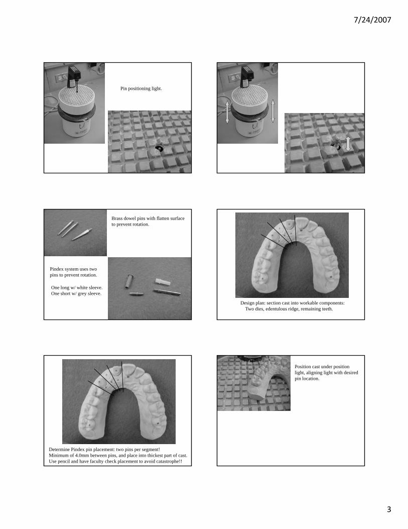
Pin positioning light.
Brass dowel pins with flatten surface to prevent rotation.
Pindex system uses two pins to prevent rotation.
One long w/ white sleeve.One short w/ grey sleeve.
Design plan: section cast into workable components:Two dies, edentulous ridge, remaining teeth.
Determine Pindex pin placement: two pins per segment!Minimum of 4.0mm between pins, and place into thickest part of cast.Use pencil and have faculty check placement to avoid catastrophe!!
Position cast under position light, aligning light with desired pin location.

7/24/2007
4
Firmly hold cast in a fixed position, grasp the base ring and “squeeze”, bringing the drill tip up into the base of the cast.
“Squeeze” until positioning light goes out!
Light out!
Release grip.
Check pin hole.
Not deep enough.
Desired pin hole depth.
Test each pin for complete seating.
Short pins act as anti-rotational features.
Sh t iShort pin placement.
L iLong pin placement.

7/24/2007
5
Sh t iShort pin placement.
L iLong pin placement.
Cast must be absolutely dry!!
Coat pin with cyanoacrylate (Superglue) and fully seat into pin hole.
For convenience, place the shorter pins first.
Insert the non-tapered end.
Long pins=white sleeves.Short pins=grey pins.
7/24/2007
6
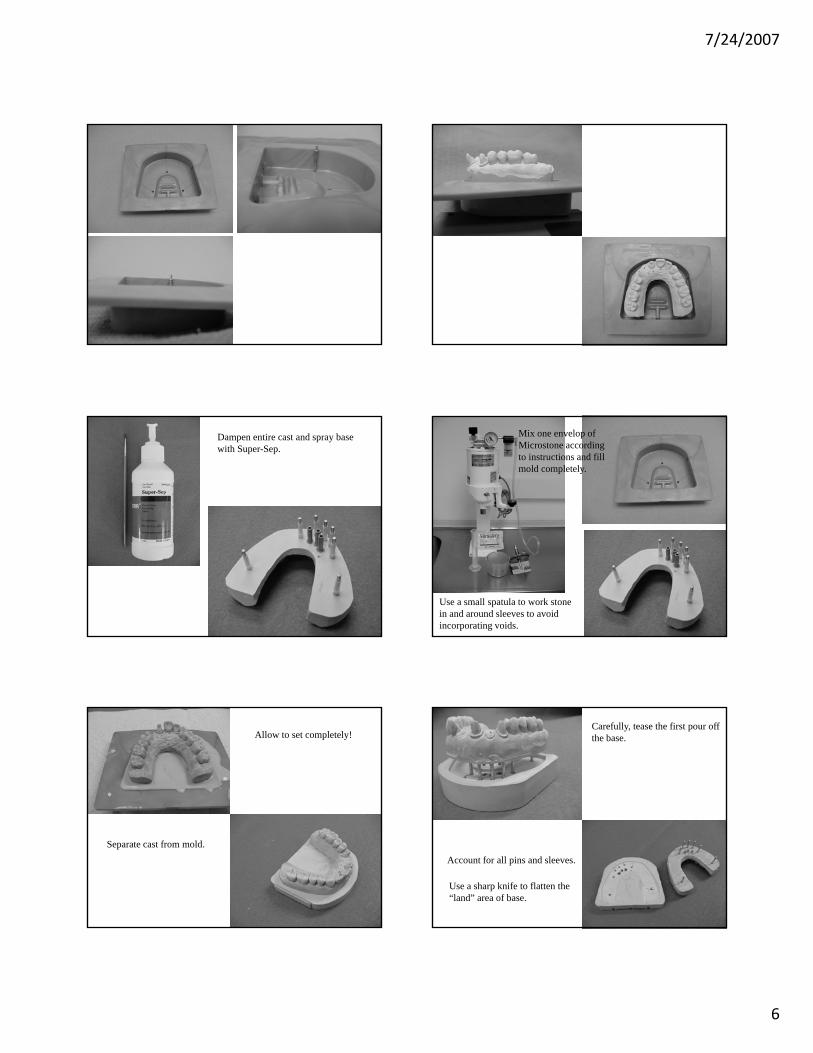
Dampen entire cast and spray base with Super-Sep.
Mix one envelop of Microstone according to instructions and fill mold completely.
Use a small spatula to work stone in and around sleeves to avoid incorporating voids.
Allow to set completely!
Separate cast from mold.
Carefully, tease the first pour off the base.
Account for all pins and sleeves.
Use a sharp knife to flatten the “land” area of base.

7/24/2007
7
Using a sharp Bard-Parker knife, remove any remnants of the base stone from the mating surface.
Check for serious voids in the base that would undermine die seating and stability.
Minor voids are ok.
Flattened “land”area.
Re-seat first pour into base and check for complete seating.
Sawing out dies.
Preparation.
Align long and short pins.
Draw a line parallel to long axis of pin and die.
Repeat for other die and edentulous space.
Repeat on lingual side.
Draw lines for saw cut.
Visualize where pins are located and draw lines to avoid cutting into pins.

7/24/2007
8
Die Trimming
Trim dies in order to provide an emergence profile for the lab to use to create proper axial contours.

7/24/2007
9
Problems Along The Way
Use a sharp saw blade.
Remedy: Cut from the apical aspect of the die.