pingu camera system to study properties of the
TRANSCRIPT
PINGU Camera System to Study Properties of the1
Antarctic Ice2
The IceCube-Gen2 Collaboration1,1 http://icecube.wisc.edu/collaboration/authors/icrc15_gen2
E-mail: [email protected]
IceCube is the world’s largest neutrino detector located at the geographic South Pole, that utilizesmore than 5000 optical sensors to observe Cherenkov light from neutrino interactions. A hot wa-ter drill was used to melt holes in the ultra-pure Antarctic ice, in which strings of optical sensorswere deployed at a depth of 1500 m to 2500 m. The recent discovery of high energy neutrinosconsistent with being of astrophysical origin, as well as precision measurements of neutrino oscil-lation parameters and competitive searches for dark matter, have demonstrated the great potentialfor ice-based neutrino telescopes. Extensions to the IceCube detector are under active considera-tion, including the PINGU multi-megaton neutrino detector with GeV threshold. Ice properties,including the refrozen ice from the optical sensor deployment, represent a major source of un-certainty for event reconstruction in IceCube. A camera system integrated with optical sensormodules could be tremendously beneficial for the interpretation of calibration measurements andto better understand ice properties. We describe a preliminary design of an on-board camerasystem and its impact on ice property measurements and geometry calibration.
Corresponding authors: D. Bose∗, M. Jeong, W. Kang, J. Kim, M. Kim, C. RottDepartment of Physics, Sungkyunkwan University, Suwon 440-746, South Korea
The 34th International Cosmic Ray Conference,30 July- 6 August, 2015The Hague, The Netherlands
∗Speaker.
c© Copyright owned by the author(s) under the terms of the Creative Commons Attribution-NonCommercial-ShareAlike Licence. http://pos.sissa.it/
Camera system D. Bose
1. Introduction3
IceCube, the world’s largest neutrino telescope, utilizes the ultra-pure Antarctic ice at the geo-4
graphic south pole as a detector medium. The recent discovery of high energy astrophysical neutri-5
nos [1, 2] by IceCube as well as a variety of other high impact results in the fields of astrophysics6
and particle physics have proven the success of the detector concept. Extensions to the IceCube7
detector, in form of a multi-megaton precision neutrino detector with an energy threshold of about a8
GeV, known as the Precision IceCube Next Generation Upgrade (PINGU) [3, 4], and a high-energy9
neutrino detector optimised for observing TeV to PeV neutrinos, known as IceCube-Gen2 [5, 6],10
are being considered. The extensions will reuse the very reliable design of IceCube’s digital optical11
models (DOMs), however several improvements are envisioned. Among the improvements con-12
sidered is an on-board camera system that is targeted at surveying the ice surrounding the optical13
sensors, which has not been measured and could be a key to reduce systematic uncertainties on14
light propagation in the ice. In this proceeding we focus on a camera system for PINGU, which15
targets the determination of the neutrino mass hierarchy and searches for dark matter.16
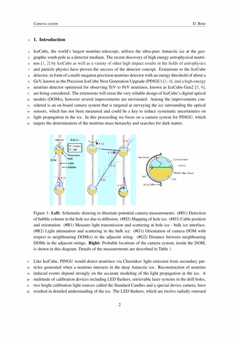
Figure 1: Left: Schematic drawing to illustrate potential camera measurements: (#H1) Detectionof bubble column in the hole ice due to diffusion. (#H2) Mapping of hole ice. (#H3) Cable positionand orientation. (#B1) Measure light transmission and scattering at hole ice - bulk ice interface.(#B2) Light attenuation and scattering in the bulk ice. (#G1) Orientation of camera DOM withrespect to neighbouring DOM(s) in the adjacent string. (#G2) Distance between neighbouringDOMs in the adjacent strings. Right: Probable locations of the camera system, inside the DOM,is shown in this diagram. Details of the measurements are described in Table 1.
Like IceCube, PINGU would detect neutrinos via Cherenkov light emission from secondary par-17
ticles generated when a neutrino interacts in the deep Antarctic ice. Reconstruction of neutrino18
induced events depend strongly on the accurate modeling of the light propagation in the ice. A19
multitude of calibration devices including LED flashers, retrievable laser systems in the drill holes,20
two bright calibration light sources called the Standard Candles and a special device camera, have21
resulted in detailed understanding of the ice. The LED flashers, which are twelve radially outward22
2

Camera system D. Bose
Objective Measurement Requirements for Camera SystemResolution Sensitivity Orientation
(#H1) Verify degassing inrefrozen ice
Scattered light from bubbles 5MP 0.1 lux Facing up
(#H2) Hole ice mapping Scattered light of the hole /bulkice interface
1 MP 0.1 lux Facingsidewise
(#H3) Cable position &orientation
Cable shadow from in the hole 1 MP 0.1 lux Facing up
(#B1) Light transmissionat hole / bulk interface
Scattering of distant LED lightin the surrounding
5 MP 0.001 lux Facingsidewise
(#B2) Scattering and ab-sorption lengths
Light distribution and scatter-ing halo on adjacent strings
5 MP 0.001 lux Facingsidewise
(#G1) Orientation ofcamera DOM
LED emission from one ormore adjacent string DOMs
1 MP 0.001 lux Facingsidewise
(#G2) Distance betweenDOMs
Observe multiple LEDs fromadjacent DOMs
5 MP 0.001 lux Facingsidewise
Table 1: Objectives of the camera system are listed in the first column and measurements in thesecond column. Requirements for the camera system to carry out those measurements are givenin columns 3-5, based on preliminary calculations. Camera sensitivities are estimated assuming abright LED with two candela intensity as light source. Objectives are grouped by hole ice stud-ies (#H1, #H2 & #H3), light propagation in the bulk ice (#B1 & #B2), and geometry calibrationmeasurements (#G1 & #G2). The required light sensitivities for the camera system are calculated,in order to detect scattered light from LEDs located in the DOMs in the same string and in theadjacent string.
pointing 405 nm LEDs on each DOM, are indispensable for the most advanced models of ice prop-23
erties, as they provide calibration points through-out the detector. Fits to their data have resulted in24
the most advanced ice model [7]. The present calibration system however has several short com-25
ings, in particular little is known about the individual environment surrounding each DOM. The26
refrozen ice in the drill hole is not very well understood and there is good reason to expect that the27
environment of each DOM could be significantly different. A low cost, high resolution on-board28
camera system paired with a bright LED for illumination deployed on each PINGU DOM (PDOM)29
could tremendously improve our understanding of the refrozen ice in the drill hole. It could yield30
qualitative information valuable in interpreting other calibration measurements, such as the LED31
flashers, and provide quantitative measurements of the ice properties.32
A camera system inside two glass spheres at the bottom of IceCube string 80 (the last deployed33
string) provides a precedent for the proposed system [8]. The system observed the formation of34
bubbles at the centre of the drill hole (referred to as bubble column) during the refreezing of the35
ice from the outside inward. The bubble column shows significantly reduced scattering length.36
The system identified impurities settling on the surface of glass sphere of the camera. Information37
about the ice and drill hole provided by the system is limited to a small region where the system is38
located.39
3

Camera system D. Bose
2. Objectives and Goals40
The main goal of the camera system is to study the properties of the refrozen ice, determine the41
location and orientation of the DOMs within the drill hole and survey the ice environment.42
A variety of measurements could be performed with a camera system, each of which comes43
with its own requirements on the positioning of the camera, its sensitivity, field of view (FOV),44
resolution, and illumination options. We describe the suite of potential measurements qualitatively45
and describe the basic requirements for the camera system to perform them.46
(1) The camera system could monitor the freeze-in process of the strings of DOMs deployed47
after melting holes using a hot water drill [9]. Little is known about the refreezing process. For48
the measurement the camera would be operated at 0◦C, and would preferentially be facing up or49
sidewise. A high-resolution color camera could best identify impurities and monitor the freeze-50
in dynamics. Triboluminescence or the formation of cracks could potentially be observed. For51
PINGU it has been proposed to degas drill water in an effort to reduce or eliminate the formation52
of bubbles. The camera system could provide immediate feedback about water quality and the53
effectiveness of degassing could be verified with the camera system, including depth dependence54
of bubble formation.55
(2) Surveying the completely refrozen drill hole is one of the highest priorites of the camera56
system. If present, the system would survey and characterize the bubble column and identify57
contaminants. The PDOM position (x-y) within the drill hole can be determined, as well as the58
relative location of the bubble column, which could lead to a non uniform photon acceptance by59
PMT. For the hole ice measurement it is most effective to have the camera pointing up and to have60
a LED for illumination located adjacent to it on the same DOM.61
(3) Another objective is to study properties of the untouched or pristine ice (referred as ’bulk62
ice’) between holes, and how light transmission is affected at the hole ice - bulk ice intersection.63
The observation of a halo of scattered light from a LED on an adjacent string could be used to64
study scattering, while the observation of the LED itself could be used to study attenuation. A65
high-resolution, high-sensitivity black and white camera would be most desirable for this purpose.66
(4) A camera system could also assist geometry measurements. By observing a LED, on the67
adjacent upper DOM, the relative orientation (around the z-axis) of the DOM with an upward fac-68
ing camera can be determined. The orientation of a DOM on an adjacent string could also be69
determined through the observation of one or more LEDs on it, this would require a high reso-70
lution camera that could resolve individual LEDs on an adjacent DOM. From the light pattern in71
the captured image, one can determine relative orientation of the camera DOM as well. Likewise,72
a camera system facing up would capture scattered light coming from LEDs in the neighbouring73
DOM in the same string and studying the light pattern we can determine relative orientations be-74
tween DOMs and their positions inside the hole. The relative depth of DOMs between adjacent75
strings could also be determined. All these information would improve the geometry calibration of76
the PINGU array, but would require precise alignment and placement of LEDs and cameras.77
(5) Finally the camera system could be beneficial to survey the DOM environment for anything78
unforeseen and also provide a way to check for any dynamic effects, which are not expected after79
freeze-in.80
4

Camera system D. Bose
Nearly all measurements benefit from a large FOV, making fisheye lenses the preferred option.81
Further, PINGU’s hexagonal deployment pattern makes in necessary for sidewise facing cameras82
to have a FOV of 60◦ to have at least one adjacent string visible. Cameras should preferably have83
high resolution and good light sensitivity to observe LEDs on adjacent strings.84
A schematic diagram of PDOMs in the hole ice along with probable camera positions are85
shown in the Figure 1. A summary of objectives, measurements and requirements based on some86
preliminary calculations are given in the Table 1.87
Neigh
borin
g str
ing
pDOM
spac
ing
Ls: scattering lengthI: led intensityCMOS
CCD
3m 20m 35m
Next
Neigh
borin
g str
ing
Figure 2: The minimum illumination required for a camera to see an LED located in the neigh-boring PDOM in the same string and at adjacent string are shown. The grey shaded area showthe illumination for a CMOS camera with at 1 s exposure time and CCD camera sensitivities asspecified by the manufacturer for an exposure time 1/60 s.
3. Camera Design and Interface88
PDOM Main Board
Figure 3: Left : Camera modules currently being tested include CMOS sensors OV2715, OV5647& OV5653 and CCD sensors RJ2315DB0PB. Right : Block diagram for the camera interface.
The camera system would consist of one or many cameras along with one or multiple bright LEDs89
with a narrow beam angle (∼20◦) as light sources. The camera system would be either mounted90
on the DOM main board or attached to the penetrator of the pressure sphere for easy assembly.91
5

Camera system D. Bose
The camera module would be mounted on a small PCB (Printed Circuit Board) of dimension ∼92
40mm×40mm along with a MCU (Micro Controller Unit) for image processing. This system93
would communicate with the main board of the DOM via SPI (Serial Peripheral Interface) as shown94
with a block diagram in the Figure 3. Cameras could be oriented facing up or facing sidewise as95
required.96
The camera system would remain in power saving mode during physics data taking and only97
be activated for calibration runs. The targeted power consumption per the camera system during98
operations is less than 1 W as the total power available per quad (4 DOMs connected together)99
is ∼2.5 W. While DOMs (PMT) will be off during camera operations it is desirable to have mul-100
tiple cameras and LEDs active at the same time to minimize time for calibration measurements.101
Following image capture, uncompressed images would be transferred to the DOM mainboard via102
SPI interface and then to the surface, where they would be saved for offline analysis. IceCube103
data transfer rates are about 40kB/s per DOM, which allow for the transfer of large uncompressed104
images within minutes.105
4. System requirements106
Various CMOS and CCD camera modules are considered as candidates for the camera system.107
Currently we are studying three CMOS cameras & one CCD camera ( see Figure 3). CMOS cam-108
eras have high resolutions (∼2MP-5MP). Resolution of CCD camera is 0.3MP. All these cameras109
can be operated over a wide range of temperatures (-30◦C to 70◦C). A lens with wide field of view110
will be mounted on the camera sensor. One of the requirements for the camera system is that it has111
a low power consumption, which favours CMOS cameras (∼ 0.3 W). Further CMOS sensors are112
inexpensive and have high resolution. CCD cameras on the other hand have significantly higher113
sensitivities, but also consume more power (∼ 1.0 W) and have a lower resolution.114
To minimise detector downtimes for calibration measurements, a camera with higher light115
sensitivity is preferred. However, some measurements might require high resolution (if not limited116
by image distortion in the glass sphere) and power constraints might favor the CMOS camera. For117
the moment we consider both CCD and CMOS cameras as candidates.118
Longer exposure times with the CMOS camera might achieve similar sensitivities to CCD119
cameras. CMOS cameras are expected to be operated in their most sensitive settings if noise levels120
are sufficiently low. The light sensitivity of a digital camera can be set through the ISO (Inter-121
national Standards Organization) number (i.e. higher number corresponds to higher sensitivity).122
Figure 2 shows the required illumination at the camera to see a typical bright LED (∼ 2-3 candela)123
as a function of distance. The required illuminance to observe a LED on the neighbouring DOM in124
the same string and in the adjacent string are around 0.1 lux and 0.001 lux respectively.125
5. Camera measurements at the lab126
We describe the camera performance measurements that will be our basis for the camera selection.127
We have setup measurements to compare and characterize: (1) camera noise, (2) light sensitivity,128
and (3) camera resolution and image distortion due to the glass sphere. Currently we have surveyed129
one CMOS camera (OV5647) to develop the series of tests that will be used for camera selection.130
6

Camera system D. Bose
Our current sample camera has 5 million pixels (2592×1944) and is currently operated through a131
Raspberry Pi for convenience. We obtained raw images in Bayer format. A Bayer filter is a RGB132
(Red, Green & Blue) color filter array on a square grid of photosensors. Each primary color red,133
green & blue has 8 bits, which means counts will go in saturation at 255 counts.134
Camera Noise : A low brightness measurement might be limited by intrinsic detector noise, hence135
we need to characterise camera noise and stability under the expected conditions in the deep ice.136
We measured the camera dark noise at room temperature in a dark box and at low temperatures137
in a freezer. Images were captured with exposure times of up to 6 seconds and for ISO 100, 400,138
and 800. Camera noise increases with exposure time and sensitivity setting (ISO value). At room139
temperature about ∼ 1% of pixels are noisy, where a noisy pixel is defined as a pixel with one or140
more counts. The number of noisy pixels and average noise count per pixel decreases significantly141
with temperature as shown in the Figure 4.142
Figure 4: Left: Average noise count per pixel as function temperature for OV5647 for ISO 800 and6s exposure. Right: The number of noisy pixels vs temperatures.
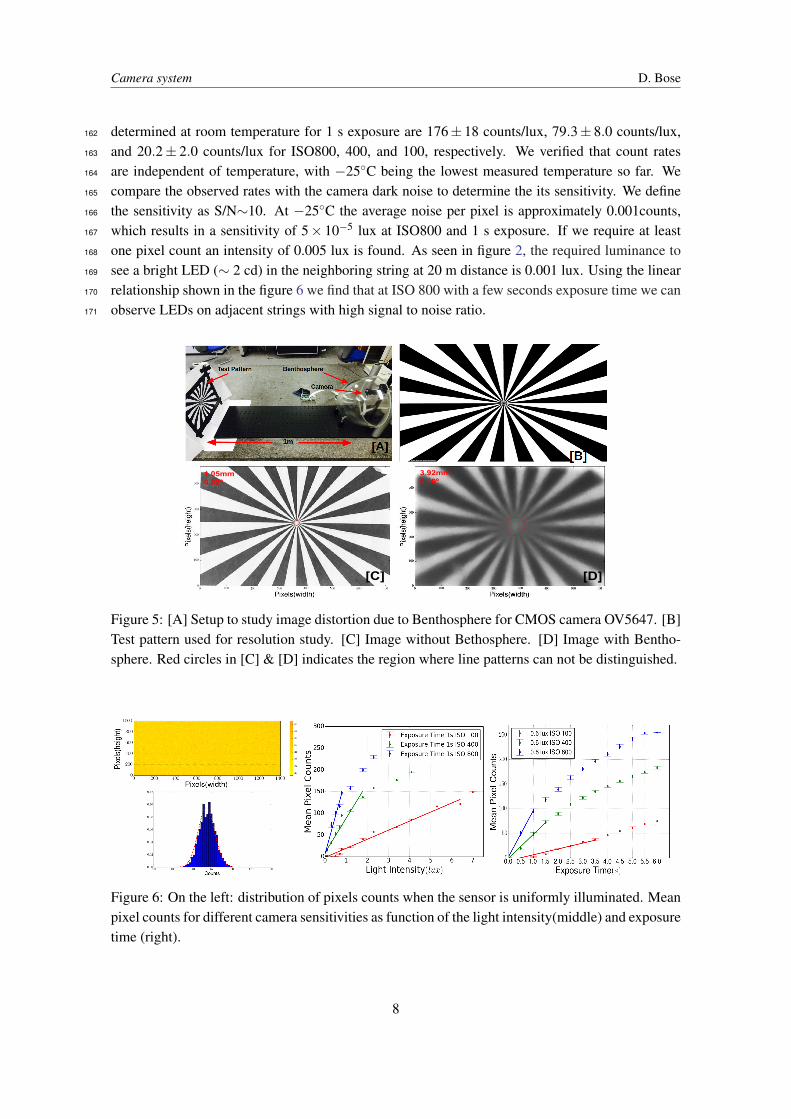
Image Resolution and Distortion: The camera system would be located inside the DOMs pres-143
sure glass sphere, called the Benthosphere. Therefore images are bound to get distorted. We144
measure image resolution under normal conditions and through the Benthosphere. As the resolu-145
tion measurement is subjective, we are investigating different independent ways to measure it. As146
an example resolution test we show the measurement with a test pattern shown in Figure 5 and147
captured images. In the test pattern black and white lines originate in the center and radiate out-148
ward. We captured images of the test pattern at 1 m distance from the camera with and without the149
Benthosphere. The relative effect of image distortion can clearly be seen in image [D] in Figure 5.150
The line pattern cannot be distinguished inside the red circles in plots [C] & [D]. As the camera un-151
der test has field of view (f.o.v.) of 60◦, by measuring the diameter of the circle we can determine152
the resolution. We find the resolution of the camera without the Benthosphere to be ∼1.05 mm153
(0.024◦) and with ∼3.92 mm (0.10◦). The Benthosphere reduces the resolution by a factor of 4.154
Due to refraction in ice, a 60◦ f.o.v. will become 45◦ f.o.v. (because index of refraction in air is155
1 and in ice 1.3). So in the ice, corresponding values for the resolution would be ∼0.76 mm &156
∼2.80 mm, respectively.157
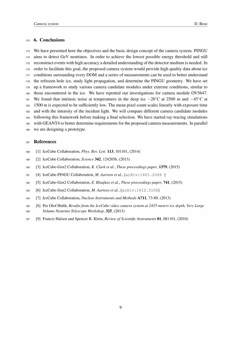
Sensitivity of the camera: To study light sensitivity of the camera, we illuminate the camera158
sensor uniformly as shown in Figure 6. The distribution is homogeneous within 5%. The mean159
pixel count varies linearly with incident light intensity and exposure time as shown. Saturation can160
be observed for pixel counts close to 255 and are not included in the linear fits. The pixel count rates161
7
Camera system D. Bose
determined at room temperature for 1 s exposure are 176± 18 counts/lux, 79.3± 8.0 counts/lux,162
and 20.2± 2.0 counts/lux for ISO800, 400, and 100, respectively. We verified that count rates163
are independent of temperature, with −25◦C being the lowest measured temperature so far. We164
compare the observed rates with the camera dark noise to determine the its sensitivity. We define165
the sensitivity as S/N∼10. At −25◦C the average noise per pixel is approximately 0.001counts,166
which results in a sensitivity of 5× 10⁻⁵ lux at ISO800 and 1 s exposure. If we require at least167
one pixel count an intensity of 0.005 lux is found. As seen in figure 2, the required luminance to168
see a bright LED (∼ 2 cd) in the neighboring string at 20 m distance is 0.001 lux. Using the linear169
relationship shown in the figure 6 we find that at ISO 800 with a few seconds exposure time we can170
observe LEDs on adjacent strings with high signal to noise ratio.171
1.05mm0.02º
[C]
3.92mm0.10º
[D]
Figure 5: [A] Setup to study image distortion due to Benthosphere for CMOS camera OV5647. [B]Test pattern used for resolution study. [C] Image without Bethosphere. [D] Image with Bentho-sphere. Red circles in [C] & [D] indicates the region where line patterns can not be distinguished.
Figure 6: On the left: distribution of pixels counts when the sensor is uniformly illuminated. Meanpixel counts for different camera sensitivities as function of the light intensity(middle) and exposuretime (right).
8
Camera system D. Bose
6. Conclusions172
We have presented here the objectives and the basic design concept of the camera system. PINGU173
aims to detect GeV neutrinos. In order to achieve the lowest possible energy threshold and still174
reconstruct events with high accuracy a detailed understanding of the detector medium is needed. In175
order to facilitate this goal, the proposed camera system would provide high quality data about ice176
conditions surrounding every DOM and a series of measurements can be used to better understand177
the refrozen hole ice, study light propagation, and determine the PINGU geometry. We have set178
up a framework to study various camera candidate modules under extreme conditions, similar to179
those encountered in the ice. We have reported our investigations for camera module OV5647.180
We found that intrinsic noise at temperatures in the deep ice −20◦C at 2500 m and −45◦C at181
1500 m is expected to be sufficiently low. The mean pixel count scales linearly with exposure time182
and with the intensity of the incident light. We will compare different camera candidate modules183
following this framework before making a final selection. We have started ray-tracing simulations184
with GEANT4 to better determine requirements for the proposed camera measurements. In parallel185
we are designing a prototype.186
References187
[1] IceCube Collaboration, Phys. Rev. Lett. 113, 101101, (2014)188
[2] IceCube Collaboration, Science 342, 1242856, (2013)189
[3] IceCube-Gen2 Collaboration, K. Clark et al., These proceedings paper, 1379, (2015)190
[4] IceCube-PINGU Collaboration, M. Aartsen et al., [arXiv:1401.2046 ]191
[5] IceCube-Gen2 Collaboration, E. Blaufuss et al., These proceedings paper, 741, (2015)192
[6] IceCube-Gen2 Collaboration, M. Aartsen et al., [arXiv:1412.5106]193
[7] IceCube Collaboration, Nuclear Instruments and Methods A711, 73-89, (2013)194
[8] Per Olof Hulth, Results from the IceCube video camera system at 2455 meters ice depth, Very Large195
Volume Neutrino Telescope Workshop, 325, (2013)196
[9] Francis Halzen and Spencer R. Klein, Review of Scientific Instruments 81, 081101, (2010)197
9