pip-usp2… · page 2 iq-pip-usp2 reference manual iq-pip-usp2 reference manual page 3 ... 5.1 a...
TRANSCRIPT
*****PIP-USP2PIP-USP2PIP-USP2PIP-USP2PIP-USP2
An IQ System® Programmable Input Processor with DSP andLoad Supervision for Crown® PIP2-Compatible Amplifiers
Printed onrecycled paper.
125981-42/02
© 2002 by Crown Audio, Inc., P.O. Box 1000, Elkhart, IN 46515-1000 U.S.A.Telephone: 574-294-8000. Fax: 574-294-8329. Trademark Notice: IQ2, SmartAmp,PIP, and PIP2 are trademarks, and Com-Tech, Crown, IOC, IQ System, Macro-Techand ODEP are registered trademarks of Crown International. Other trademarks arethe property of their respective owners.
Obtaining Other Language Versions:To obtain information in another language about the use of this product, pleasecontact your local Crown Distributor. If you need assistance locating your localdistributor, please contact Crown at 574-294-8200.
Note: The information provided in this manual wasdeemed accurate as of the publication date. How-ever, updates to this information may have occurred.To obtain the latest version of this manual, pleasevisit the Crown website at www.crownaudio.com.

IQ-PIP-USP2
Page 3IQ-PIP-USP2 Reference Manual
IQ-PIP-USP2
Page 2 IQ-PIP-USP2 Reference Manual
Quick Install ProcedureThis procedure is provided for those who are already familiar with Crown’s IQSystem® and who would like to install the IQ-PIP-USP2 in the shortest time possible.Less experienced installers or those wishing a full explanation of the installationprocedure are encouraged to go to Section 3 where the full installation procedureis described.
Prepare the IQ-PIP-USP2:
1. Set the IQ address switch S1 (see Figures 2.1 and 3.1) on the IQ-PIP-USP2 toan unused IQ address. (Tip: Record the IQ address on the small field labeled“IQ ADDRESS” that is provided on the PIP panel.)
2. Set the Input/Output Scaling switch S3 (see Figures 2.1 and 3.2) for the desiredscaling.
Prepare the amplifier:
3. Turn down the level controls of the amplifier and turn off the amplifier.
4. Unplug the power cord of the amplifier from the AC mains.
5. Remove the existing PIP™ or cover panel from the amplifier back panel (twoscrews).
Install the IQ-PIP-USP2 into the amplifier:6. Carefully ground yourself to the chassis of the amplifier before installing the IQ-
PIP-USP2. It is a good idea to maintain ground contact between yourself andthe amplifier while inserting the module into the amplifier in the next step.
7. Turn the PIP upside down so you can clearly see the two ribbon cable connec-tors located on the underside of the board near the back corner (see Figure2.1). Attach the ribbon cables from your amp to the ribbon-cable connectors.The 20-pin cable should be connected first, then the 18-pin cable should beconnected. Both ribbon cables should run untwisted from the amplifier to thePIP module.
Important: Be careful when attaching the ribbon cable to the connector thatthe cable is properly seated before applying pressure to the connector. Forc-ing the cable onto the connector could cause the keying tabs, which ensureproper pin alignment, to break. Connecting the ribbon cables with improperpin alignments may result in damage to the PIP
When both cables are firmly attached, turn the IQ-PIP-USP2 back to an uprightposition and insert into the PIP opening in the back of the amplifier. Take carewhile inserting the PIP to make sure you do not crimp, pinch or stretch theribbon cables.
8. Tighten the two PIP mounting screws until it is secured to the amplifier backpanel, making sure the supplied star-washers penetrate the powder-coat fin-ish of the PIP panel for good ground connection.
Install the wiring:9. Connect the IQ-PIP-USP2 to the IQ System via the Crown Bus (see Section
3.4 if more information is needed).
10. Connect the audio signal wiring to the IQ-PIP-USP2 (see Section 3.4 if moreinformation is needed).
11. Connect the amplifier back to the AC mains.
The information furnished in this manual does not include all of the detailsof design, production, or variations of the equipment. Nor does it coverevery possible situation which may arise during installation, operation ormaintenance. If you need special assistance beyond the scope of thismanual, please contact Crown Technical Support.
Crown Technical Support1718 W. Mishawaka Rd., Elkhart, Indiana 46517 U.S.A.
Phone: 800-342-6939 (North America, Puerto Rico and VirginIslands) or 219-294-8200
Fax: 574-294-8301 Internet: http://www.crownaudio.com
WARNINGTO REDUCE THE RISK OF ELECTRIC
SHOCK, DO NOT EXPOSE THISEQUIPMENT TO RAIN OR MOISTURE!
FCC COMPLIANCE NOTICEThis equipment has been tested and found to comply with thelimits for a Class A digital Device, pursuant to Part 15 of the FCCRules. These limits are designed to provide reasonableprotection against harmful interference when the equipment isoperated in a commercial environment. This equipmentgenerates, uses and can radiate radio frequency energy and, ifnot installed and used in accordance with the instruction manual,may cause harmful interference to radio communications.Operation of this equipment in a residential area is likely to causeharmful interference in which case the user will be required tocorrect the interference at his own expense.
“The user is cautioned that any changes or modifications notexpressly approved by Crown International could void the user’sauthority to operate the equipment.”
IQ-PIP-USP2
Page 5IQ-PIP-USP2 Reference Manual
IQ-PIP-USP2
Page 4 IQ-PIP-USP2 Reference Manual
ILLUSTRATIONS
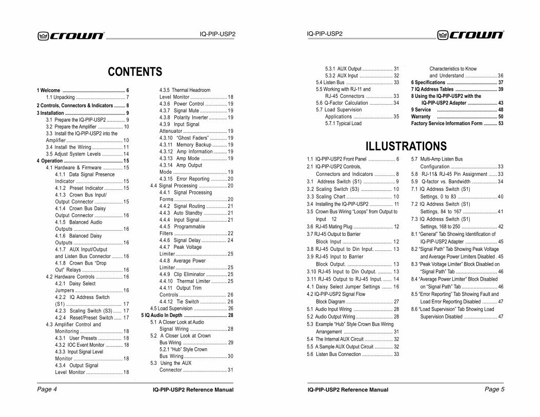
CONTENTS1 Welcome ................................................... 6
1.1 Unpacking ........................................ 72 Controls, Connectors & Indicators ......... 83 Installation ................................................. 9
3.1 Prepare the IQ-PIP-USP2 ............... 93.2 Prepare the Amplifier .................... 103.3 Install the IQ-PIP-USP2 into theAmplifier .............................................. 103.4 Install the Wiring ......................... 113.5 Adjust System Levels ................. 14
4 Operation ................................................ 154.1 Hardware & Firmware ................ 15
4.1.1 Data Signal PresenceIndicator ...................................... 154.1.2 Preset Indicator ............... 154.1.3 Crown Bus Input/Output Connector ....................... 154.1.4 Crown Bus DaisyOutput Connector ....................... 164.1.5 Balanced AudioOutputs ........................................ 164.1.6 Balanced DaisyOutputs ........................................ 164.1.7 AUX Input/Outputand Listen Bus Connector ......... 164.1.8 Crown Bus �DropOut� Relays ................................. 16
4.2 Hardware Controls ...................... 164.2.1 Daisy SelectJumpers ....................................... 164.2.2 IQ Address Switch(S1) ............................................. 174.2.3 Scaling Switch (S3) ....... 174.2.4 Reset/Preset Switch ...... 17
4.3 Amplifier Control andMonitoring ................................... 184.3.1 User Presets ................... 184.3.2 IOC Event Monitor .............. 184.3.3 Input Signal LevelMonitor ........................................ 184.3.4 Output SignalLevel Monitor .............................. 18
4.3.5 Thermal HeadroomLevel Monitor .............................. 184.3.6 Power Control .................. 194.3.7 Signal Mute ...................... 194.3.8 Polarity Inverter ............... 194.3.9 Input SignalAttenuator .................................... 194.3.10 �Ghost Faders� .............. 194.3.11 Memory Backup ............ 194.3.12 Amp Information ........... 194.3.13 Amp Mode ..................... 194.3.14 Amp OutputMode ............................................ 194.3.15 Error Reporting ............. 20
4.4 Signal Processing ....................... 204.4.1 Signal ProcessingForms ........................................... 204.4.2 Signal Routing ................. 214.4.3 Auto Standby ................... 214.4.4 Input Signal ...................... 214.4.5 ProgrammableFilters ........................................... 224.4.6 Signal Delay .................... 244.4.7 Peak VoltageLimiter .......................................... 254.4.8 Average PowerLimiter .......................................... 254.4.9 Clip Eliminator ................. 254.4.10 Thermal Limiter ............. 254.4.11 Output TrimControls ...................................... 264.4.12 Tie Switch ..................... 26
4.5 Load Supervision ........................... 265 IQ Audio In Depth ................................... 28
5.1 A Closer Look at AudioSignal Wiring .............................. 28
5.2 A Closer Look at CrownBus Wiring .................................... 295.2.1 �Hub� Style CrownBus Wiring ................................... 30
5.3 Using the AUXConnector .................................... 31
5.3.1 AUX Output ......................... 315.3.2 AUX Input ........................... 32
5.4 Listen Bus ...................................... 335.5 Working with RJ-11 and
RJ-45 Connectors ...................... 335.6 Q-Factor Calculation ................... 345.7 Load Supervision
Applications ................................ 355.7.1 Typical Load
Characteristics to Knowand Understand .......................... 36
6 Specifications ......................................... 377 IQ Address Tables .................................. 398 Using the IQ-PIP-USP2 with the
IQ-PIP-USP2 Adapter ........................ 439 Service ................................................. 48Warranty ................................................. 50Factory Service Information Form ........... 53
1.1 IQ-PIP-USP2 Front Panel ...................... 62.1 IQ-PIP-USP2 Controls,
Connectors and Indicators ................. 83.1 Address Switch (S1) .......................... 93.2 Scaling Switch (S3) ......................... 103.3 Scaling Chart ..................................... 103.4 Installing the IQ-PIP-USP2 ................... 113.5 Crown Bus Wiring �Loops� from Output to
Input 123.6 RJ-45 Mating Plug ................................ 123.7 RJ-45 Output to Barrier
Block Input ........................................ 123.8 RJ-45 Output to Din Input. .............. 133.9 RJ-45 Input to Barrier
Block Output. .................................... 133.10 RJ-45 Input to Din Output. ........... 133.11 RJ-45 Output to RJ-45 Input. ....... 144.1 Daisy Select Jumper Settings ........ 164.2 IQ-PIP-USP2 Signal Flow
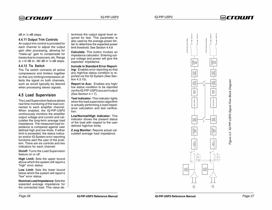
Block Diagram ...................................... 275.1 Audio Input Wiring ................................ 285.2 Audio Output Wiring .............................. 285.3 Example �Hub� Style Crown Bus Wiring
Arrangement ........................................ 315.4 The Internal AUX Circuit ....................... 325.5 A Sample AUX Output Circuit ............... 325.6 Listen Bus Connection ......................... 33
5.7 Multi-Amp Listen BusConfiguration ...................................... 33
5.8 RJ-11& RJ-45 Pin Assignment ....... 335.9 Q-factor vs. Bandwidth ..................... 347.1 IQ Address Switch (S1)
Settings, 0 to 83 ................................ 407.2 IQ Address Switch (S1)
Settings, 84 to 167 ............................ 417.3 IQ Address Switch (S1)
Settings, 168 to 250 ............................. 428.1 �General� Tab Showing Identification of
IQ-PIP-USP2 Adapter .......................... 458.2 �Signal Path� Tab Showing Peak Voltage
and Average Power Limiters Disabled . 458.3 �Peak Voltage Limiter� Block Disabled on
�Signal Path� Tab .................................. 468.4 �Average Power Limiter� Block Disabled
on �Signal Path� Tab ............................. 468.5 �Error Reporting� Tab Showing Fault and
Load Error Reporting Disabled ............ 478.6 �Load Supervision� Tab Showing Load
Supervision Disabled ........................... 47
IQ-PIP-USP2
Page 7IQ-PIP-USP2 Reference Manual
IQ-PIP-USP2
Page 6 IQ-PIP-USP2 Reference Manual
1.1 UnpackingThe unit is shipped in a protectiveantistatic bag.
CAUTION: STATIC ELECTRICITYMAY DAMAGE THE UNIT. Use cau-tion when handling the unit. Care-fully ground yourself BEFORE touch-ing the unit. Avoid unnecessarilytouching the components or solderpads on the circuit boards.
Please unpack and inspect the unitfor any damage that may have oc-
curred during transit. If damage isfound, notify the transportation com-pany immediately. Only you, theconsignee, may initiate a claim withthe carrier for shipping damage.Crown will be happy to cooperatefully as needed. Save the shippingcarton as evidence of damage forthe shipper’s inspection.
Even if the unit arrived in perfectcondition, as most do, save all pack-ing materials. NEVER SHIP THEUNIT WITHOUT THE FACTORYPACK.
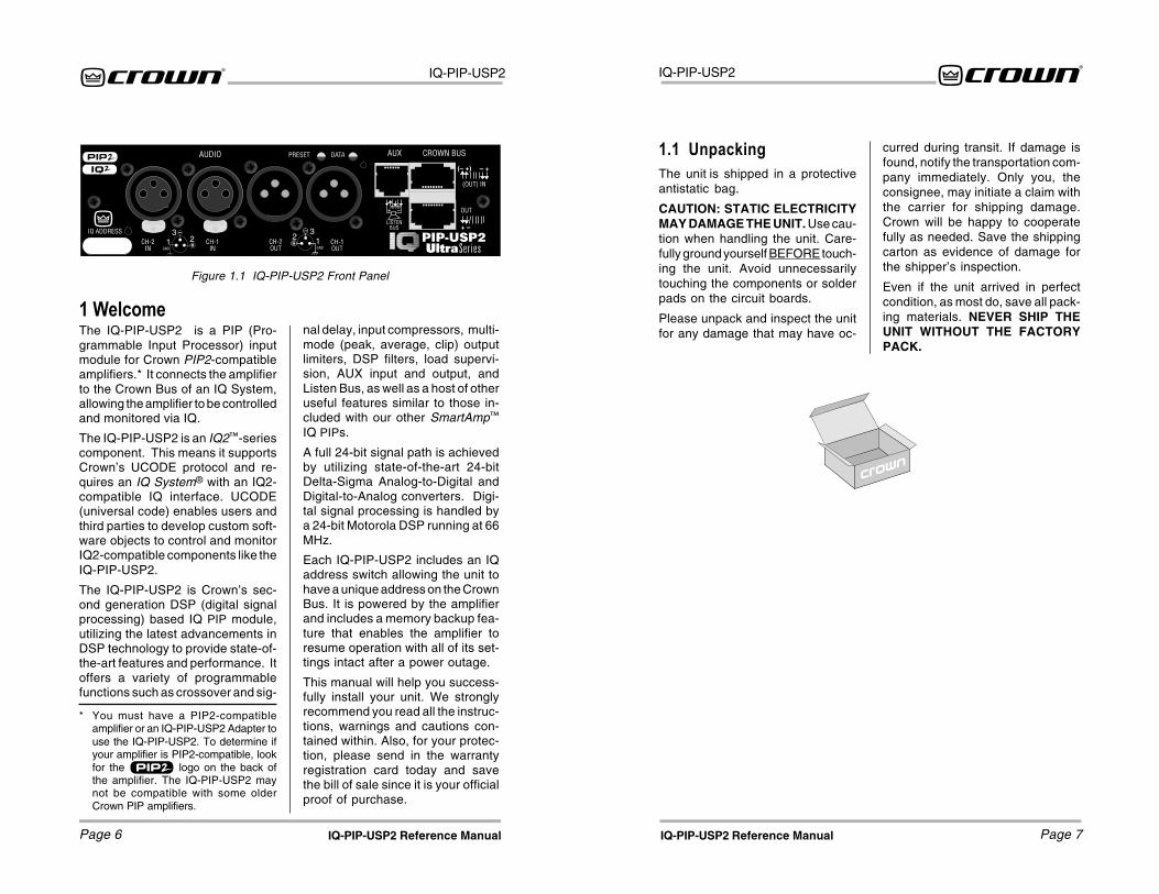
1 WelcomeThe IQ-PIP-USP2 is a PIP (Pro-grammable Input Processor) inputmodule for Crown PIP2-compatibleamplifiers.* It connects the amplifierto the Crown Bus of an IQ System,allowing the amplifier to be controlledand monitored via IQ.
The IQ-PIP-USP2 is an IQ2™-seriescomponent. This means it supportsCrown’s UCODE protocol and re-quires an IQ System® with an IQ2-compatible IQ interface. UCODE(universal code) enables users andthird parties to develop custom soft-ware objects to control and monitorIQ2-compatible components like theIQ-PIP-USP2.
The IQ-PIP-USP2 is Crown’s sec-ond generation DSP (digital signalprocessing) based IQ PIP module,utilizing the latest advancements inDSP technology to provide state-of-the-art features and performance. Itoffers a variety of programmablefunctions such as crossover and sig-
Figure 1.1 IQ-PIP-USP2 Front Panel
nal delay, input compressors, multi-mode (peak, average, clip) outputlimiters, DSP filters, load supervi-sion, AUX input and output, andListen Bus, as well as a host of otheruseful features similar to those in-cluded with our other SmartAmp™
IQ PIPs.
A full 24-bit signal path is achievedby utilizing state-of-the-art 24-bitDelta-Sigma Analog-to-Digital andDigital-to-Analog converters. Digi-tal signal processing is handled bya 24-bit Motorola DSP running at 66MHz.
Each IQ-PIP-USP2 includes an IQaddress switch allowing the unit tohave a unique address on the CrownBus. It is powered by the amplifierand includes a memory backup fea-ture that enables the amplifier toresume operation with all of its set-tings intact after a power outage.
This manual will help you success-fully install your unit. We stronglyrecommend you read all the instruc-tions, warnings and cautions con-tained within. Also, for your protec-tion, please send in the warrantyregistration card today and savethe bill of sale since it is your officialproof of purchase.
* You must have a PIP2-compatibleamplifier or an IQ-PIP-USP2 Adapter touse the IQ-PIP-USP2. To determine ifyour amplifier is PIP2-compatible, lookfor the logo on the back ofthe amplifier. The IQ-PIP-USP2 maynot be compatible with some olderCrown PIP amplifiers.

IQ-PIP-USP2
Page 9IQ-PIP-USP2 Reference Manual
IQ-PIP-USP2
Page 8 IQ-PIP-USP2 Reference Manual
3 InstallationBefore beginning, please carefullynote:
CAUTION: STATIC ELECTRICITYMAY DAMAGE THE IQ-PIP-USP2MODULE. Use caution when han-dling the unit. Carefully ground your-self BEFORE touching the IQ-PIP-USP2 module. Avoid unnecessarilytouching the components or solderpads on the circuit boards.
3.1 Prepare the IQ-PIP-USP21. Set the IQ address switch S1. By
giving each IQ component aunique address, it can beindividually controlled andmonitored. Whenever the IQSystem wants to send a commandto just one IQ component, it firstsends its address and then thecommand down the Crown Bus.
S1 has eight segments because itactually contains eight tinyswitches inside. The word “ON” isprinted on the switch along itsupper left side to indicate the ONposition and the switches arenumbered along the bottom(Figure 3.1).
Each of the eight switches in S1has a value which doubles as theswitch number increases. Forexample switch 1 has a value of 1;switch 2 has a value of 2; switch 3has a value of 4; switch 4 has avalue of 8 and so on.
The address is determined byadding the values of all “ON”switches. In Figure 3.1, switches 1,3, 4 and 7 are on. Simply add thevalues to find the address:1+4+8+64=77.
A convenient series of IQ addresstables are included in Section 6.The tables show the switchsettings for all 250 addresses.
No two IQ components of thesame type which are connected tothe same Crown Bus can have thesame address.* Suppose, forexample, an IQ System has twoCrown Bus loops, 1 and 2, and thisIQ-PIP-USP2 is to be installed intoloop 1 and given an address of 77.No other IQ PIPs can be given thesame address in loop 1. However,an IQ PIP in loop 2 can have thesame address.
Different IQ components in thesame Crown Bus loop can havethe same address. For example,both an IQ–USM 810 mixer/processor and an IQ-PIP-USP2can use address 77 in the sameloop.
Figure 3.1 Address Switch (S1)
Figure 2.1 IQ-PIP-USP2 Controls, Connectors and Indicators
2 Controls, Connectors & Indicators
* Note: All IQ PIP modules (IQ-PIP-DSP,IQ-PIP-MEM, IQ-PIP-SMT, etc.) areconsidered the same type, and so maynot share the same address on thesame Crown Bus.
IQ-PIP-USP2
Page 11IQ-PIP-USP2 Reference Manual
IQ-PIP-USP2
Page 10 IQ-PIP-USP2 Reference Manual
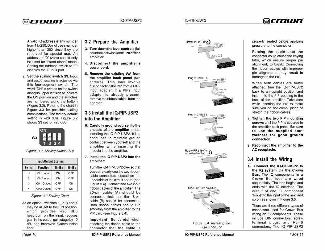
5. Remove the existing PIP fromthe amplifier back panel (twoscrews). This may involvedisconnecting the PIP from a PIP2input adapter. If a PIP2 inputadapter is already present,remove the ribbon cables from theadapter.
3.3 Install the IQ-PIP-USP2into the Amplifier6. Carefully ground yourself to the
chassis of the amplifier beforeinstalling the IQ-PIP-USP2. It is agood idea to maintain groundcontact between yourself and theamplifier while inserting themodule into the amplifier.
7. Install the IQ-PIP-USP2 into theamplifier:
Turn the IQ-PIP-USP2 over so thatyou can clearly see the two ribbon-cable connectors located on theunderside of the circuit board (seeFigure 3.4). Connect the two inputribbon cables of the amplifier. The20-pin cable (A) should beconnected first, then the 18-pincable (B) should be connected.Both ribbon cables should runsmoothly from the amplifier to thePIP card (see Figure 3.4).
Important: Be careful whenattaching the ribbon cable to theconnector that the cable is
Figure 3.4 Installing theIQ-PIP-USP2
3.2 Prepare the Amplifier3. Turn down the level controls (full
counterclockwise) and turn off theamplifier.
4. Disconnect the amplifier’spower cord.
A valid IQ address is any numberfrom 1 to 250. Do not use a numberhigher than 250 since they arereserved for special use. Anaddress of “0” (zero) should onlybe used for “stand alone” mode.Setting the address switch to “0”disables the IQ bus port.
2. Set the scaling switch S3. Inputand output scaling is adjusted viathis four-segment switch. Theword “ON” is printed on the switchalong its upper left side to indicatethe ON position and the switchesare numbered along the bottom(Figure 3.2). Refer to the chart inFigure 3.3 for possible scalingcombinations. The factory-defaultsetting is +20 dBu. Figure 3.2shows S3 set for +20 dBu.
S3
Figure 3.2 Scaling Switch (S3)
gnilacStuptuO/tupnI
hctiwS noitcnuF uBd02+ uBd01+
1 tupnI1HC NO FFO
2 tupnI2HC NO FFO
3 tuptuO1HC FFO NO
4 tuptuO2HC FFO NO
Figure 3.3 Scaling Chart
properly seated before applyingpressure to the connector.
Forcing the cable onto theconnector could cause the keyingtabs, which ensure proper pinalignment, to break. Connectingthe ribbon cables with improperpin alignments may result indamage to the PIP.
When both cables are firmlyattached, turn the IQ-PIP-USP2back to an upright position andinsert into the PIP opening in theback of the amplifier. Take carewhile inserting the PIP to makesure you do not crimp, pinch orstretch the ribbon cables.
8. Tighten the two PIP mountingscrews until the PIP is secured tothe amplifier back panel. Be sureto use the supplied star-washers for good groundconnection.
9. Reconnect the amplifier to theAC receptacle.
3.4 Install the Wiring10. Connect the IQ-PIP-USP2 to
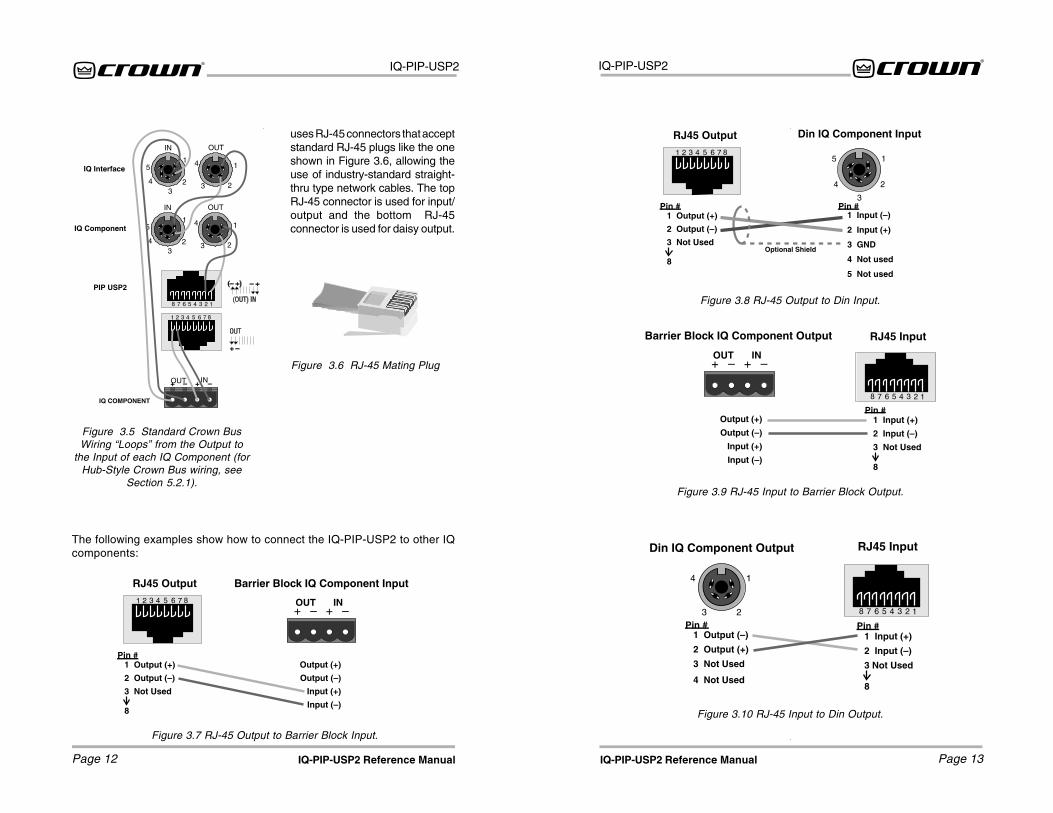
the IQ system via the CrownBus. The IQ components in aCrown Bus loop are wiredsequentially. The loop begins andends with the IQ interface. Theoutput of one IQ component“loops” to the input of the next andso on as shown in Figure 3.5.
There are three different types ofconnectors used for Crown Buswiring on IQ components. Theseinclude DIN connectors, screwterminal plugs, and RJ-45connectors. The IQ-PIP-USP2
As an option, switches 1, 2, 3 and 4may be all set to the ON position,which provides +20 dBuheadroom on the input, reducesgain in the output gain stage by 10dB, and improves system noisefloor.
IQ-PIP-USP2
Page 13IQ-PIP-USP2 Reference Manual
IQ-PIP-USP2
Page 12 IQ-PIP-USP2 Reference Manual
Figure 3.8 RJ-45 Output to Din Input.
Figure 3.7 RJ-45 Output to Barrier Block Input.
Figure 3.6 RJ-45 Mating Plug
The following examples show how to connect the IQ-PIP-USP2 to other IQcomponents:
Figure 3.5 Standard Crown BusWiring “Loops” from the Output to
the Input of each IQ Component (forHub-Style Crown Bus wiring, see
Section 5.2.1).
uses RJ-45 connectors that acceptstandard RJ-45 plugs like the oneshown in Figure 3.6, allowing theuse of industry-standard straight-thru type network cables. The topRJ-45 connector is used for input/output and the bottom RJ-45connector is used for daisy output.
Figure 3.9 RJ-45 Input to Barrier Block Output.
Figure 3.10 RJ-45 Input to Din Output.
IQ-PIP-USP2
Page 15IQ-PIP-USP2 Reference Manual
IQ-PIP-USP2
Page 14 IQ-PIP-USP2 Reference Manual
4 OperationWith an IQ-PIP-USP2 module,your Crown amplifier can be moni-tored and controlled from a remotelocation through the use of an IQSystem. This PIP module featuresSmartAmp™ capabilities which willenable the amplifier to function au-tomatically. For example, the IQ-PIP-USP2 can automatically turn off thehigh voltage supplies of the amplifierwhen no input signal is present. Thiscan lower electrical usage and pro-vide long-term cost savings. The IQ-PIP-USP2 can also automaticallylimit the audio signal and detect andreport various problems.
The IQ-PIP-USP2 also features digi-tal signal processing capabilitiesincluding signal delays and a widevariety of filters.
In addition, the IQ-PIP-USP2Load Supervision feature has theability to verify the status of the loadsin real time.
The IQ-PIP-USP2 uses Crown’s IQ2protocol. This makes it possible for auser to design custom graphic dis-play modules to control and monitorthe unit with IQ2-compatible IQ soft-ware. This allows even greater flex-ibility within Crown’s IQ software viacustom control pages. Plus, the IQ2protocol provides for third-party pro-gramming for system controllerssuch as those from AMX andCrestron.
The following sections describe theIQ-PIP-USP2 features and opera-tion. Where specified, some featuresare accessed via controls locatedon the unit itself. However, many ofthe features can be controlled or
configured using IQ for Windows soft-ware. Commands are transmittedvia an IQ interface to the specified IQcomponent (an IQ2-compatible in-terface is required). Please contactyour Crown representative orCrown’s Technical Support Group ifyou are unfamiliar with IQ software.
4.1 Hardware4.1.1 Data Signal PresenceIndicatorAn amber Data Signal Presence In-dicator (DATA) is provided on thefront panel. It flashes whenever com-mands addressed to the IQ-PIP-USP2 are received. To assist withtroubleshooting, an option thatforces the DATA indicator to remainlit is available through IQ software.
4.1.2 Preset IndicatorA green PRESET indicator is pro-vided on the front panel. This indica-tor signals the number of the cur-rently selected preset by emitting aseries of flashes which match thepreset number, followed by a pause.The indicator will continuously re-peat the number selected until achange is made to any setting.
4.1.3 Crown Bus Input/OutputConnectorAn RJ-45 connector provides bothinput and output connection to theCrown Bus. This connector is usedfor input in a conventional CrownBus wiring configuration, and canbe used for both input and outputwhen a “hub” style Crown Bus wir-ing configuration is implemented(see Section 5.2). Drop-out relaysmaintain loop integrity in the eventpower is removed from the IQ-PIP-
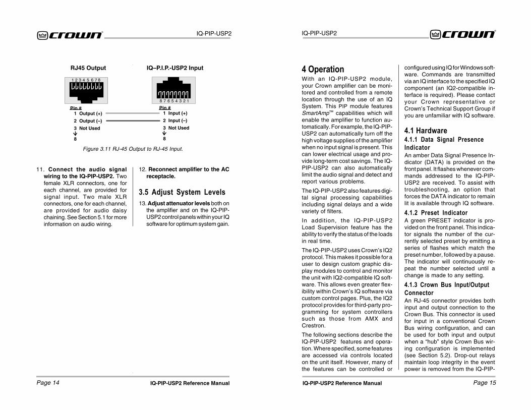
11. Connect the audio signalwiring to the IQ-PIP-USP2. Twofemale XLR connectors, one foreach channel, are provided forsignal input. Two male XLRconnectors, one for each channel,are provided for audio daisychaining. See Section 5.1 for moreinformation on audio wiring.
Figure 3.11 RJ-45 Output to RJ-45 Input.
12. Reconnect amplifier to the ACreceptacle.
3.5 Adjust System Levels13. Adjust attenuator levels both on
the amplifier and on the IQ-PIP-USP2 control panels within your IQsoftware for optimum system gain.

IQ-PIP-USP2
Page 17IQ-PIP-USP2 Reference Manual
IQ-PIP-USP2
Page 16 IQ-PIP-USP2 Reference Manual
An 8-section DIP switch is used toset the IQ address of the unit. A validIQ address is any number from 1 to250. Numbers higher than 250 arereserved for special use. An ad-dress of “0” places the unit in stand-alone mode. In this mode, the IQbus port is disabled and the PIP willnot function with IQ software.
This switch is located on the under-side of the circuit board. Each IQcomponent on a Crown Bus is givena unique IQ address so it can beindependently controlled and moni-tored. Two or more IQ componentsof the same type should NEVER havethe same address on the sameCrown Bus loop.
For information on setting the IQAddress Switch, see Section 3.1.
4.2.3 Scaling Switch (S3)A 4-section DIP switch is used to setthe input and output scaling. Thisswitch is located on the under-sideof the circuit board. The factory-default setting is +20dBu.
For information on setting inputand output scaling, see Section 3.1.
4.2.4 Reset/Preset SwitchA recessed reset/preset switch, ac-cessible from outside the PIP panel,performs two functions. First, it en-ables the IQ-PIP-USP2 to be re-stored to factory default settings,and second, allows the user to re-call any of ten presets. A straight-ened paper clip or similar small ob-ject is required to press the resetswitch.
To select one of the ten presets,complete the following steps:
Remove all input signals. With the
power on, briefly press the switch forless than two seconds to togglethrough the 10 user-defined presetsstored in firmware. Each press willincrement the selected preset byone. After the switch is released, theDATA light will flash rapidly for amoment, then the PRESET indicatorwill blink to indicate the preset num-ber selected. Restore input signals.
To restore the unit to the factorydefault settings, complete the fol-lowing steps:
Remove all input signals. With thepower on, press the switch and holdfor more than 2 seconds, or until theDATA indicator blinks twice, and allsettings will be reset to factory de-fault. When the switch is released,the DATA indicator will flash rapidlyfor a moment. Restore input signals.
To clear all memory and set tofactory default presets:
Important: This action will re-writethe flash memory and erase storedpresets. The settings will be resetto factory default, with the firmwarere-writing to flash memory.
Remove all input signals. Applypower. Press and hold the switch.The Data and Preset lights will si-multaneously flash. After 7 flashes,release the switch when the lightsare on. Lights will flash back andforth, then data light will flash byitself. If this does not occur, repeatthe process.
After the unit has been reset to thefactory default settings, it will behavelike a standard PIP until it is repro-grammed by an IQ System. Restoreinput signals.
USP2.
4.1.4 Crown Bus Daisy OutputConnectorAn RJ-45 connector is provided fornormal daisy wiring output to thenext device on the loop in the CrownBus.
4.1.5 Balanced Audio InputsA female XLR connector is providedfor balanced audio input to eachchannel of the amplifier. Do not usethe Ch.2 input if the amplifier isconfigured in either Bridge or Par-allel-Mono mode.
4.1.6 Balanced Daisy OutputsA male XLR connector is providedfor balanced audio daisy chainingfor each channel. Each daisy outputconnector can be set to pass pro-cessed or unprocessed signal fromits respective channel via jumpersettings.
4.1.7 AUX Input/Output andListen Bus ConnectorAn RJ-11 connector provides threefunctions. The AUX output delivers15 VDC at 10 mA maximum outputwhen switched on and may be con-trolled via software or may be pro-grammed to switch when a fail con-dition is present on any channel.*The high-impedance (10 K ohm) AUXinput can sense logic signals andcan be programmed to activate sys-tem mute or report fault conditionswhen a logic high is present. (SeeSection 5.3.2 for more information.)
Either amplifier channel’s output canbe monitored as a balanced linelevel signal which is sent to pins 1and 6 of the RJ-11 connector (soft-ware selectable).
4.1.8 Crown Bus �Drop Out�Relays“Drop out” relays are provided onthe Crown Bus ports to maintain thecontinuity of the IQ communicationloop even if the IQ-PIP-USP2loses power.
4.2 Hardware ControlsThe following IQ-PIP-USP2 controlsare accessed via hardware switcheslocated on the unit:
4.2.1 Daisy Select JumpersJumpers select through or pro-cessed signal daisy routing to theChannel 1 and Channel 2 daisy XLRconnectors. The Channel 1 daisyconnector can be set for through(IN) or processed (OUT) signal fromChannel 1, and the Channel 2 daisyconnector can be set for through(IN) or processed (OUT) signal fromChannel 2. See Figure 4.1.
4.2.2 IQ Address Switch (S1)
* The AUX output uses inverse logicwhen it is configured to report a failcondition. Normally high, it switcheslow when any channel fails a test. In thisway it can also indicate a power loss.
DSY1
DSY2
OUT IN
Figure 4.1 Daisy Select Jumpersettings for through routing for bothChannel 1 and Channel 2 signals.
IQ-PIP-USP2
Page 19IQ-PIP-USP2 Reference Manual
IQ-PIP-USP2
Page 18 IQ-PIP-USP2 Reference Manual
Each channel’s high-voltage supplycan be independently turned on andoff.
4.3.7 Signal MuteThe output signal of each channelcan be independently muted. Thisfunction typically provides 80 dB ormore of attenuation.
IMPORTANT: The daisy chain out-puts are also muted by activation ofthis function if selected for “pro-cessed” out.
4.3.8 Polarity InverterThe polarity of the input signal ofeach channel can be independentlyinverted.
4.3.9 Input Signal AttenuatorAn attenuator at the input of eachchannel is used to control the inputsignal level. Each attenuator has arange from 0 dB to –80 dB in ½ dBsteps. (Zero equals no attenuation.)
4.3.10 �Ghost Faders�These indicators let you monitor thesignal path gain where it may differfrom manual gain set on input at-tenuation and output trim as the re-sult of limiting or compression. Theyappear as flying faders “behind” theinput attenuators.
4.3.11 Memory BackupA memory backup feature is pro-vided which can be disabled, if de-sired. The factory default setting is“enabled.” When enabled, thememory backup stores all run-timeparameters that can be controlledby the IQ software into nonvolatileflash memory. Memory backup oc-curs within 2 seconds after any pa-rameter change. When disabled, allrun-time parameters are returned to
the last backed-up values wheneverthe unit loses power.
CAUTION: Care should be taken tobackup “safe” levels for the inputattenuators and output trim controls.Changes made after disablingbackup are not saved; therefore, it ispossible for the memory backup fea-ture to be turned off with “unsafe”levels stored. This may result in sig-nificantly greater system gain thenext time power is re-applied to theIQ-PIP-USP2.
4.3.12 Amp InformationSeveral useful items of informationabout the host amplifier are deter-mined by the IQ-PIP-USP2 at start-up. These include manufacturer,model, date code, serial number,and revision level. These can beprinted from the system inventory.
4.3.13 Amp ModeThe Stereo (Dual), Bridge-Mono orParallel-Mono mode of the amplifiercan be stored in the IQ-PIP-USP2’smemory so the IQ System is awareof the position of the amplifier’s out-put mode switch. Storing this settingserves as an “electronic reminder” tothe system; however, the actualmode of the amplifier cannot be con-trolled with this setting. The softwareamp mode setting can be displayedor modified via IQ for Windows soft-ware.
4.3.14 Amp Output ModeOn Com-Tech series amplifiers, theoutput mode of the amplifier can bestored in the IQ-PIP-USP2’s memoryso the IQ System is aware of theamplifier’s output mode setting. Thissoftware switch also scales the out-
4.3 Amplifier Control andMonitoringThe following IQ-PIP-USP2 featuresare accessed via IQ for Windowssoftware.
4.3.1 User PresetsThe parameters for all functions canbe saved as presets. A total of tenuser presets can be stored in the IQ-PIP-USP2’s flash memory. Presetnames are stored on the PIP
4.3.2 IOC Event MonitorThe Input/Output Comparator (IOC®)of each channel of the amplifier canbe monitored by the IQ System. TheIOC circuitry acts as a sensitive dis-tortion meter to provide you proof ofdistortion-free performance. If dis-tortion of any kind equals or exceeds0.05%, the IOC circuit will cause anIOC Event Monitor on the front of theamplifier to flash. The IQ-PIP-USP2can cause a warning to flash on yourcomputer screen via IQ for Windowssoftware indicating an IOC event,Also, it can report IOC events to it’sAUX port.
4.3.3 Input Signal Level MonitorThe input signal level of each chan-nel can be monitored. This monitorfeature has a range from +20 dBu to–40 dBu in ½-dB steps.
4.3.4 Output Signal LevelMonitorThe output signal level of each chan-nel of the amplifier can be moni-tored. This monitor feature has arange from 0 dB to –40 dB where 0
dB is referenced to the rated outputvoltage of the amplifier model.*
The IQ-PIP-USP2 features scaledoutput level meters. By factory de-fault, the meters are calibrated suchthat 0 dB equals the amplifier’s ratedoutput into 4 or 8 ohms. If the IQ-PIP-USP2 is installed into a Com-Tech®
amplifier, the meters default to 0 dBequals 70 Vrms. Changing the 4/8 -70V mode software switch selectsthe respective scaling.
4.3.5 Thermal Headroom LevelMonitorThe Thermal Headroom level** ofeach channel of the amplifier can bemonitored by the IQ software. Thislevel represents the percent of avail-able power/thermal capacity that iscurrently being used within the out-put section of the amplifier. Whenthe thermal headroom level reaches100%, the amplifier cannot produceany more power and it will begin tolimit the drive level to the outputdevices to protect them from toomuch stress.*** The Thermal Limiterfeature of the IQ-PIP-USP2 can beset to engage upon a pre-selectedthermal level. (See Section 4.3.15)
4.3.6 Power/Standby Control
* This is assumed to be 70V or the rated8-ohm output for Com-Tech amplifiersor the rated 8-ohm output voltage for allother amplifiers.
** Thermal Headroom on your Crown am-plifier may be labeled Output DeviceEmulation Protection (ODEP)
*** See the amplifier’s Reference orOwner’s Manual for more informationabout ODEP and how it works.
IQ-PIP-USP2
Page 21IQ-PIP-USP2 Reference Manual
IQ-PIP-USP2
Page 20 IQ-PIP-USP2 Reference Manual
2x2 Dual Processor, the defaultform configuration, provides true ste-reo signal processing, with all signalprocessing options available on bothchannels.
1x2 Crossover/Processor + EQprovides Auto Standby, Input Com-pression Limiter, and Crossoverand DSP Filter processing optionson the signal for Channel 1 only, Thesignal is then routed to the Channel1 and Channel 2 signal processingblocks for further processing androuting to the amplifier.
The AMCb+ form mimics the func-tion of Crown’s PIP-AMCb.* The sig-nal is routed only to Channel 1 forDSP crossover, then the signal isrouted to the Channel 1 and Chan-nel 2 signal processing blocks forfurther processing and routing tothe amplifier. In the AMCb form,Box EQ is specified for Channel 1,and CD Horn EQ is specified forChannel 2.
4.4.2 Signal RoutingUsing IQ for Windows software, youcan choose either or both Channel 1and Channel 2 XLR inputs to drivethe processing path for each chan-nel of the IQ-PIP-USP2. You canalso route the output of either chan-nel to Channel 1 or Channel 2 ampli-fier inputs.
4.4.3 Auto StandbyThe Auto Standby feature automati-cally turns off the high-voltage sup-
plies of the amplifier when no audiosignal is detected at the input for apredetermined period of time. Thechannels are controlled indepen-dently. There are four parameterswhich control this feature:
On/Off: Turns this function on/off.
Input Gate Level: Sets the level, indB, below which the high voltagesupply of an amplifier channel willbe turned off. The range is from +16dBu to –40 dBu.
Turn-Off Delay: Sets the time, inminutes, that the input signal mustremain below the Standby Level be-fore the channel’s high-voltage sup-ply is turned off. The range is from 0to 255 minutes. A setting of 0 (zero)yields a turn-off delay of approxi-mately 2 seconds to facilitate setupof the function.
Power-On Delay: Enables or dis-ables the IQ address turn-on delay.This delay prevents all the amplifi-ers from turning on at the sameinstant and tripping power break-ers. The turn-on delay is calculatedby: 10 msec x IQ address value. Itmay be desirable to disable thisfeature so that the first syllable ofspeech is not missed in a voicepage application.
4.4.4 Input SignalCompressor/LimiterAn input signal compressor/limiteris available for each channel. Thereare five parameters which controlthis feature:
* For more information about the PIP-AMCb, consult the PIP-AMCb Refer-ence Manual, or contact CrownTechnical Support.
put level meters for calibrated outputindication.
4.3.15 Error ReportingFour different error conditions can bedetected by the IQ-PIP-USP2. Theyinclude IOC, Thermal, Fault, and Load.Reporting for each condition can beindividually configured for output tothe AUX port, the IQ for Windowssoftware, or both. If you choose sys-tem software notification, you will re-ceive notice of the fault condition viathe IQ System. If you choose Aux outnotification, the Aux out signal willswitch from ON to OFF when a se-lected error has occurred. If you pre-fer, reporting can be switched offcompletely. Following is a descrip-tion of each error condition:
IOC: You can choose to be informedwhen an excessive number of IOCevents occur over a unit of time ineither channel of the amplifier. WhenIOC error reporting is on, an alert willbe generated when the number ofIOC events per unit of time specifiedexceeds a count that you set. TheCount control lets you set a numberof IOC events per unit of time allowedbefore an error is generated. Therange is 1 to 100. The Time controllets you set the unit of time in secondsduring which the number of IOC errorevents are counted for possible errorreporting. The range is 1 to 10 sec-onds.
Thermal: You can choose to bewarned if the thermal level rises abovea predetermined level. The Thresh-old control lets you set the thermallevel above which an error messagewill be reported. The range is from 1to 100%.
Fault: You can choose to be warnedwhen an amplifier “fault” conditionoccurs when a channel fails. PIP2-compatible devices monitor a “fault”signal from the amplifier.
Load: You can choose to be warnedif the impedance of the load beingdriven by the amplifier falls out of apre-selected range. See Section 4.5for instructions on setting up theload supervision feature.
4.4 Signal ProcessingThe following DSP signal process-ing features are controlled via IQ forWindows software.
4.4.1 Signal ProcessingFormsMany of the advanced features ofthe IQ-PIP-USP2 are accessed fromthe IQ for Windows software Formpanel.* This special feature allowsthe audio signal to be processedand routed according to three avail-able “form” specifications: 2x2 DualProcessor, 1x2 Crossover/Proces-sor + EQ, and AMCb+.
When a new form type is selected,the required signal processingblocks are automatically arrangedto fit the scheme of the selectedform. The result is a preset “tem-plate” for signal processing thatmakes it faster and easier for you totailor your system to your specificneeds.
* For more information about the struc-ture of the forms environment within IQfor Windows, consult the documenta-tion and help files which accompanythe software.

IQ-PIP-USP2
Page 23IQ-PIP-USP2 Reference Manual
IQ-PIP-USP2
Page 22 IQ-PIP-USP2 Reference Manual
Low-Pass Crossover Filter
Description: This filter rolls off highfrequencies at a rate determined bythe shape parameter. The filter iscommonly used to feed the low fre-quency portion of an audio signal towoofers or subwoofers. It can becombined with a high-pass cross-over filter to create a band-passcrossover filter for driving mid-rangedrivers.
Passband gain: Fixed at unity.
Frequency: Sets the –3 dB cornerfrequency of the filter. The range is20 Hz to 20 kHz.
Shape: Sets the response shape ofthe filter. Available response shapesare: 1st-order Butterworth, 2nd-or-der Butterworth, 3rd-orderButterworth, 4th-order Butterworth,2nd-order Bessel, 3rd-order Bessel,4th-order Bessel and 4th-orderLinkwitz-Riley.
High-Pass Crossover Filter
Description: This filter rolls off lowfrequencies at a rate determined bythe shape parameter. The filter iscommonly used to feed the highfrequency portion of an audio signalto horns or tweeters. It can be com-bined with a low-pass crossover fil-ter to create a band-pass crossoverfilter for driving mid-range drivers.
Passband gain: Fixed at unity.
Frequency: Sets the –3 dB cornerfrequency of the filter. The range is20 Hz to 20 kHz.
Shape: Sets the response shape ofthe filter. Available response shapesare: 1st-order Butterworth, 2nd-or-der Butterworth, 3rd-orderButterworth, 4th-order Butterworth,2nd-order Bessel, 3rd-order Bessel,4th-order Bessel and 4th-orderLinkwitz-Riley.
Parametric Equalization Filter
Description: This filter boosts or cutsa relatively narrow frequency bandlike a band-pass filter. It is com-monly used to correct specificanomalies in the response of driv-ers.
Passband Gain: Sets the amount ofboost or cut for the filter. The rangeis +12 dB to –24 dB.
Frequency: Sets the center fre-quency of the filter. The range is 20Hz to 20 kHz.
Q: Sets the width and slope of thefilter. The range is 0.1 to 30. Thelower the Q, the wider the filter andthe better the transient responseand visa versa.
Low-Pass Equalization Filter
Description: This filter combines thefunctions of the parametric equal-ization filter to boost or cut a rela-tively narrow frequency band with alow-pass filter to roll of the frequen-cies above the center frequency.*
Frequency: Sets the center fre-quency of the filter. The range is 20Hz to 20 kHz.
On/Off: Turns this function on or off.
Threshold: Sets the threshold, indB, above which the compressoracts. The level is measured at theinput to the PIP and corresponds tothe level shown on an input meter.The compressor is “feed-forward,”meaning that the level detection pointis located before the gain controlstage. The range is from +16 dBu to–40 dBu.
Attack Time: Sets the attack time ofthe compressor. The attack time isdefined as the time it takes the com-pressor to attenuate the input signalby 10 dB. The range is from 1 milli-second to 2 seconds.
Release Time: Sets the release timeof the compressor. The release timeis defined as the time it takes thecompressor to increase the inputgain by 10 dB. The range is 100milliseconds to 30 seconds.
Compressor Ratio: Sets the com-pression ratio for the compressor.The range is 1, 2, 4, 8, 16, 32, ∞ to 1.*
4.4.5 Programmable FiltersEach channel can have as many aseight different cascaded filters (theactual number depends on the mixof filters chosen). There are sevendifferent filter types from which tochoose.
Low-Pass Crossover Filter (1st–4th order)
High-Pass crossover Filter (1st–4th order)
Parametric Equalization Filter (2ndorder only)
Low-Pass Equalization Filter (2ndorder only)
High-Pass Equalization Filter (2ndorder only)
Low-Pass Shelving Equalization(1st order only)
High-Pass Shelving Equalization(1st order only)
DSP filters can be processed pre orpost crossover, depending uponwhich form the IQ-PIP-USP2 is con-figured in (see the IQ for Windowsdocumentation for more informationabout forms).
All filters have IIR based topologiesto insure a proper magnitude/phaserelationship for use in professionalaudio applications such as equal-izer or crossover (dividing) networks.Each channel has a total of eight“biquad” filter cells.**
All filters with adjustable Q-factorscan be set in fractions of an octave.See Section 5.4 for information aboutcalculating Q-factors.
An indicator in the software showshow much DSP resources are beingused by the selected filters. One 3rdor 4th order filter uses the equivalentof two 1st or 2nd order filters.
1st, 2nd, 3rd and 4th-order re-sponses result in 6, 12, 18 and 24dB/octave roll-offs, respectively.
A description and list of the param-eters of each filter type are pre-sented next:
** “Biquad” refers to the double quadraticequations which mathematically de-scribe each filter implemented in thedigital signal processor.* 1:1 is the same as “off.”

IQ-PIP-USP2
Page 25IQ-PIP-USP2 Reference Manual
IQ-PIP-USP2
Page 24 IQ-PIP-USP2 Reference Manual
onds to 500 milliseconds in 1 milli-second steps.
“Fine” Delay: Sets the amount ofsignal delay. The range is 1.2916milliseconds to 100 milliseconds in20.83 millisecond steps. (The mini-mum delay of 1.2916 milliseconds isinherent in the DSP system design.)
The net delay through the IQ-PIP-USP2 is the sum of the coarse andfine delay settings. Use of both con-trols provides a means for greaterdelay control. For example, theCoarse Delay control can be ad-justed to provide cabinet-to-cabinetalignment, while the Fine Delay con-trol can provide alignment within acluster or cabinet.
4.4.7 Peak Voltage LimiterThis limits the peak voltage output ofthe amplifier. There are four param-eters which control this limiter.
On/Off: Turns the limiter on or off.
Attack: Attack time is adjustablefrom 10 milliseconds to 100 millisec-onds per 10 dB of overdrive.
Release: Release rate is adjustablefrom 100 milliseconds to 10 sec-onds per 10 dB or release.
Threshold: Absolute voltage thresh-old is adjustable from 12 Vpk to 255Vpk in 1 volt steps.
4.4.8 Average Power LimiterLimits the long-term power outputfrom the amp. The actual outputlimiter threshold is determined byan absolute power threshold andthe nominal load impedance set-ting. There are five parameters whichcontrol this limiter.
On/Off: Turns the limiter on or off.
Average Power Threshold: Thethreshold is adjustable from 10 to1000 watts.*
Nominal Load Impedance: Thenominal load impedance is settablefrom 1 to 1000 ohms, and should beset to correspond to the nominalimpedance rating of the load con-nected to the respective channel.
Attack Time: Adjustable from 1 sec-ond to 30 seconds in 1 second in-crements.
Release Time: Adjustable from 1second to 30 seconds in 1 secondincrements.
4.4.9 Clip EliminatorThis limiter eliminates amplifier clip-ping by monitoring IOC signals. Theonly control for this limiter is On/Off.
4.4.10 Thermal LimiterA thermal limiter is provided to limitamplifier output as a function of avail-able thermal headroom, allowingsmooth system level reduction whilepreventing amplifier overload. Thereare four parameters which controlthis feature:
On/Off: Turns the thermal limiter onor off.
Threshold: Sets the thermal level,in percent, above which limiting willbegin. The range is from 1 to 100%.
Attenuation: Sets the amount, indB, that the input signal level will beattenuated for each percentagepoint that the thermal level exceedsthe trigger level. The range is ½ to 6
* The average power threshold shouldbe set per the loudspeaker’s “long-term” power rating (consult yourspeaker documentation).
Q: Sets the width, slope and gain ofthe filter. The range is 0.1 to 30. Thelower the Q, the wider the filter, thelower the gain and the better thetransient response and visa versa.Gain examples: A Q of 2 will result in6 dB of gain at the center frequencyand a Q of 4 will result in 12 dB ofgain.
High-Pass Equalization Filter
Description: This filter combines thefunctions of the parametric equal-ization filter to boost or cut a rela-tively narrow frequency band with ahigh-pass filter to roll of the frequen-cies below the center frequency.* Itis commonly used to create a B6
(6th-order Butterworth) response ina vented loudspeaker enclosure.
Frequency: Sets the center fre-quency of the filter. The range is 20Hz to 20 kHz.
Q: Sets the width, slope and gain ofthe filter. The range is 0.1 to 30. Thelower the Q, the wider the filter, thelower the gain and the better thetransient response and visa versa.Gain examples: A Q of 2 will result in6 dB of gain at the center frequencyand a Q of 4 will result in 12 dB ofgain.
Low-Pass Shelving Equalization
Filter
Description: This filter boosts or cutslow frequencies by the specifiedamount of gain. When used to cutrather than boost, the filter acts likea high-pass filter rather than a low-pass filter. It has a fixed 1st -orderslope (6 dB/octave).
Passband Gain: Sets the amount ofboost or cut for the filter. The rangeis +12 dB to –24 dB.
Frequency: Sets the –3 dB cornerfrequency of the filter. The range is20 Hz to 20 kHz.
High-Pass Shelving Equalization
Filter
Description: This filter boosts or cutshigh frequencies by the specifiedamount of gain. When used to cutrather than boost, the filter acts likea low-pass rather than a high-passfilter. It has a fixed 1st-order slope (6dB/octave). It is commonly used tocompensate for the natural high-frequency roll-off of constant direc-tivity horns.
Passband Gain: Sets the amount ofboost or cut for the filter. The rangeis +12 dB to –24 dB.
Frequency: Sets the +3 dB cornerfrequency of the filter. The range is20 Hz to 20 kHz.
4.4.6 Signal DelaySignal delay can be set for eachchannel. The delay for each channelcan be set using “Coarse” or “Fine”adjustment controls:
“Coarse” Delay: Sets the amount ofsignal delay. The range is 0 millisec-
* The low and high-pass equalization fil-ters can be cascaded to form uniqueinter-order crossover-type filters.
IQ-PIP-USP2
Page 27IQ-PIP-USP2 Reference Manual
IQ-PIP-USP2
Page 26 IQ-PIP-USP2 Reference Manual
Fig
ure
4.2
IQ-P
IP-U
SP
2 S
igna
l Flo
w B
lock
Dia
gram
dB in ½-dB steps.
4.4.11 Output Trim ControlsAn output trim control is provided foreach channel to adjust the outputgain after processing, allowing for“make-up” gain to compensate forlosses due to crossovers, etc. Rangeis +12 dB to –80 dB in ½-dB steps.
4.4.12 Tie SwitchThe Tie switch connects all activecompressors and limiters togetherso that any limiting/compression af-fects the signal on both channels,such as would typically be desiredwhen processing stereo signals.
4.5 Load SupervisionThe Load Supervision feature allowsreal time monitoring of the load con-nected to each amplifier channel.When enabled, the IQ-PIP-USP2continuously monitors the amplifieroutput voltage and current and cal-culates the long-term average loadimpedance. The measured load im-pedance is compared against userdefined high and low limits. If eitherlimit is exceeded, the status indica-tor and/or IQ System error reportingfunctions alert the user of the prob-lem. There are six controls and twoindicators for each channel:
On/off: Turns the Load Supervisionfeature on or off.
High Limit: Sets the upper boundabove which the system will report a“high” error status.
Low Limit: Sets the lower boundbelow which the system will report a“low” error status.
Nominal Load Impedance: Sets theexpected average impedance forthe connected load. This value de-
termines the output signal level re-quired for test. This parameter isalso used by the average power lim-iter to determine the expected powerlimit threshold. See Section 4.4.8
Calculate: This button invokes animpedance calculator. Entering out-put voltage and power will give theexpected impedance.
Include in Standard Error Report-ing: Enables error reporting so thatany high/low status condition is re-ported via the IQ System (See Sec-tion 4.3.15).
Report to Aux: Enables any high/low status condition to be reportedvia the IQ-PIP-USP2 aux port output(See Section 4.1.7).
Test Indicator: This indicator lightswhen the load supervision algorithmis actually performing a load imped-ance calculation and test verifica-tion.
Low/Normal/High Indicator: Thisindicator shows the present statusof the load with respect to the userdefined high/low limits.
Z avg Monitor: Reports actual cal-culated average load impedance.
IQ-PIP-USP2
Page 29IQ-PIP-USP2 Reference Manual
IQ-PIP-USP2
Page 28 IQ-PIP-USP2 Reference Manual
• The same IQ address can be usedmore than once (once per loop permodel).
Single Loop Advantages(with IQ-INT II interfaces)
• The IQ System can send andretrieve data faster in a single loop.
• “Real time” level display of agreater number of units ispossible.
The IQ-PIP-USP2 can be connectedto the Crown Bus with inexpensivetwisted-pair wiring (shielded orunshielded). If fiber optic wiring isrequired contact the Crown Techni-cal Support Group (see page 2).
Here are some guidelines for twisted-pair wiring:
• Use shielded twisted-pair wire atleast 26 AWG in size wheninterference is a problem. The wireshould be of good quality andshould have low capacitance—30picofarads/foot or less is good.(West Penn 452 or an equivalentwire works well.) The shield servestwo purposes: First, it helps
5.2 A Closer Look atCrown Bus WiringThe IQ-PIP-USP2 must be con-nected to a Crown Bus loop havingan IQ2-compatible IQ interface inorder for the IQ System to control ormonitor it. The Crown Bus is a serialcommunication loop designed totransmit IQ commands and data. Asimplemented in the IQ-PIP-USP2, itis a 20 milliamp current loop operat-ing at a BAUD rate of 38.4 K. Theloop must be unbroken to functionproperly.
If the system includes an IQ–INT IIinterface, it can accept eight differ-ent Crown Bus loops or zones. Di-viding the sound system into differ-ent zones, each with its own CrownBus loop, can have several advan-tages. The following list contraststhose advantages with those of asingle loop.
Multiloop Advantages
• A break in communication in oneloop does not affect other loops.
• Over 250 IQ components of thesame type can be used in asystem.
5 IQ Audio In DepthThis section provides additional in-formation about Crown’s IQ Systemwith special guides to aid in the
• When using unbalanced lines,keep the cables as short aspossible. Avoid lengths greaterthan 10 feet (3 meters).
• Do not run audio input cablestogether with high-level wiringsuch as loudspeaker wires or ACcords. (This lessens the chance ofhum or noise being induced intothe input cables.)
• Do not connect audio and datagrounds together. For example,do not connect the audio ground tothe Crown Bus ground.
installation and use of the IQ-PIP-USP2. For more information aboutany of these topics, contact CrownTechnical Support.
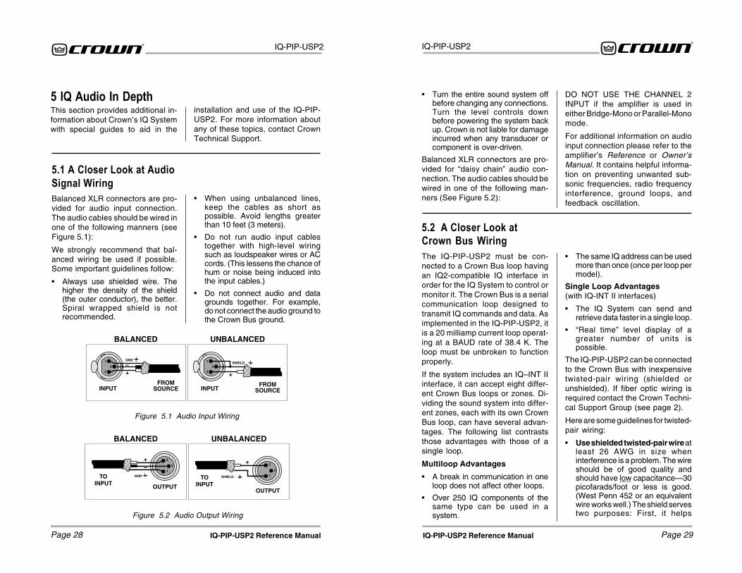
5.1 A Closer Look at AudioSignal WiringBalanced XLR connectors are pro-vided for audio input connection.The audio cables should be wired inone of the following manners (seeFigure 5.1):
We strongly recommend that bal-anced wiring be used if possible.Some important guidelines follow:
• Always use shielded wire. Thehigher the density of the shield(the outer conductor), the better.Spiral wrapped shield is notrecommended.
TOINPUT
TOINPUT OUTPUT
OUTPUT
Figure 5.2 Audio Output Wiring
Figure 5.1 Audio Input Wiring
• Turn the entire sound system offbefore changing any connections.Turn the level controls downbefore powering the system backup. Crown is not liable for damageincurred when any transducer orcomponent is over-driven.
Balanced XLR connectors are pro-vided for “daisy chain” audio con-nection. The audio cables should bewired in one of the following man-ners (See Figure 5.2):
DO NOT USE THE CHANNEL 2INPUT if the amplifier is used ineither Bridge-Mono or Parallel-Monomode.
For additional information on audioinput connection please refer to theamplifier’s Reference or Owner’sManual. It contains helpful informa-tion on preventing unwanted sub-sonic frequencies, radio frequencyinterference, ground loops, andfeedback oscillation.
IQ-PIP-USP2
Page 31IQ-PIP-USP2 Reference Manual
IQ-PIP-USP2
Page 30 IQ-PIP-USP2 Reference Manual
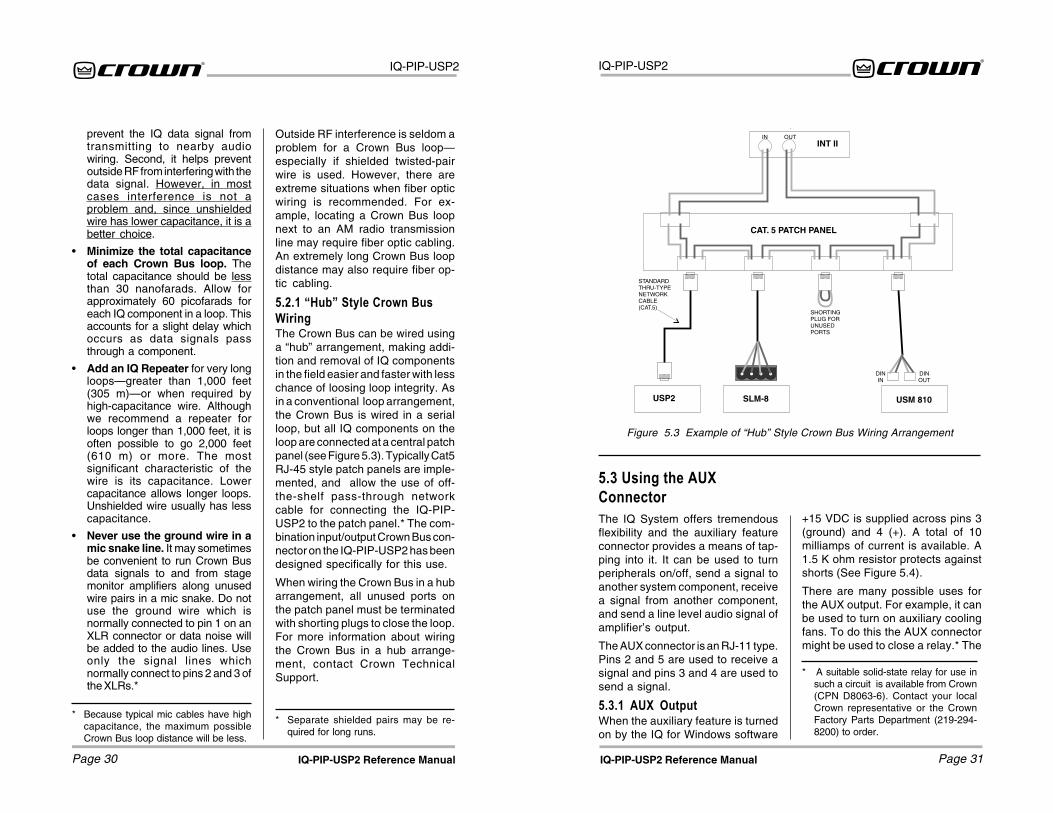
Figure 5.3 Example of “Hub” Style Crown Bus Wiring Arrangement
* Separate shielded pairs may be re-quired for long runs.
* Because typical mic cables have highcapacitance, the maximum possibleCrown Bus loop distance will be less.
prevent the IQ data signal fromtransmitting to nearby audiowiring. Second, it helps preventoutside RF from interfering with thedata signal. However, in mostcases interference is not aproblem and, since unshieldedwire has lower capacitance, it is abetter choice.
• Minimize the total capacitanceof each Crown Bus loop. Thetotal capacitance should be lessthan 30 nanofarads. Allow forapproximately 60 picofarads foreach IQ component in a loop. Thisaccounts for a slight delay whichoccurs as data signals passthrough a component.
• Add an IQ Repeater for very longloops—greater than 1,000 feet(305 m)—or when required byhigh-capacitance wire. Althoughwe recommend a repeater forloops longer than 1,000 feet, it isoften possible to go 2,000 feet(610 m) or more. The mostsignificant characteristic of thewire is its capacitance. Lowercapacitance allows longer loops.Unshielded wire usually has lesscapacitance.
• Never use the ground wire in amic snake line. It may sometimesbe convenient to run Crown Busdata signals to and from stagemonitor amplifiers along unusedwire pairs in a mic snake. Do notuse the ground wire which isnormally connected to pin 1 on anXLR connector or data noise willbe added to the audio lines. Useonly the signal lines whichnormally connect to pins 2 and 3 ofthe XLRs.*
Outside RF interference is seldom aproblem for a Crown Bus loop—especially if shielded twisted-pairwire is used. However, there areextreme situations when fiber opticwiring is recommended. For ex-ample, locating a Crown Bus loopnext to an AM radio transmissionline may require fiber optic cabling.An extremely long Crown Bus loopdistance may also require fiber op-tic cabling.
5.2.1 �Hub� Style Crown BusWiringThe Crown Bus can be wired usinga “hub” arrangement, making addi-tion and removal of IQ componentsin the field easier and faster with lesschance of loosing loop integrity. Asin a conventional loop arrangement,the Crown Bus is wired in a serialloop, but all IQ components on theloop are connected at a central patchpanel (see Figure 5.3). Typically Cat5RJ-45 style patch panels are imple-mented, and allow the use of off-the-shelf pass-through networkcable for connecting the IQ-PIP-USP2 to the patch panel.* The com-bination input/output Crown Bus con-nector on the IQ-PIP-USP2 has beendesigned specifically for this use.
When wiring the Crown Bus in a hubarrangement, all unused ports onthe patch panel must be terminatedwith shorting plugs to close the loop.For more information about wiringthe Crown Bus in a hub arrange-ment, contact Crown TechnicalSupport.
5.3 Using the AUXConnectorThe IQ System offers tremendousflexibility and the auxiliary featureconnector provides a means of tap-ping into it. It can be used to turnperipherals on/off, send a signal toanother system component, receivea signal from another component,and send a line level audio signal ofamplifier’s output.
The AUX connector is an RJ-11 type.Pins 2 and 5 are used to receive asignal and pins 3 and 4 are used tosend a signal.
5.3.1 AUX OutputWhen the auxiliary feature is turnedon by the IQ for Windows software
+15 VDC is supplied across pins 3(ground) and 4 (+). A total of 10milliamps of current is available. A1.5 K ohm resistor protects againstshorts (See Figure 5.4).
There are many possible uses forthe AUX output. For example, it canbe used to turn on auxiliary coolingfans. To do this the AUX connectormight be used to close a relay.* The
* A suitable solid-state relay for use insuch a circuit is available from Crown(CPN D8063-6). Contact your localCrown representative or the CrownFactory Parts Department (219-294-8200) to order.
IN
DININ
DINOUT
SHORTINGPLUG FORUNUSEDPORTS
OUTINT II
CAT. 5 PATCH PANEL
USP2 SLM-8 USM 810
STANDARDTHRU-TYPENETWORKCABLE(CAT.5)

IQ-PIP-USP2
Page 33IQ-PIP-USP2 Reference Manual
IQ-PIP-USP2
Page 32 IQ-PIP-USP2 Reference Manual
* A negative signal can also be used as alogic low because the signal is inter-nally clamped to protect the internalcircuitry.
relay would then turn the fans on oroff. This is shown in Figure 5.5.
By monitoring the operating condi-tion of amplifiers with the IQ Systemsoftware, the need for additionalcooling would be apparent. Thesame software could then be usedto turn on the appropriate AUX con-nector. (For more information aboutturning the auxiliary feature on/off,consult the IQ for Windows softwaredocumentation.)
5.3.2 AUX InputDepending on the IQ software beingused, the AUX connector can beused to sense the presence of aninput signal across pins 2 (+) and 5(ground). A +5 to +15 VDC signal atthe input will be interpreted as alogic “high” and will be communi-cated to the Crown Bus where a host
Figure 5.4 The Internal AUX Circuit
Figure 5.6 Listen Bus Connection
Figure 5.5A Sample AUX Output Circuit
5.4 Listen BusUse the diagram in Figure 5.6 toconnect an audio monitoring sys-tem, such as a headphone preamp,to the IQ-PIP-USP2 Listen Bus.
computer or controller can act uponit. A signal less than +1.6 VDC isinterpreted as a logic “low.”*
5.5 Working with RJ-11and RJ-45 ConnectorsPin assignments for standard RJ-11and RJ-45 connectors are indicatedin Figure 5.8.
Amp 1
Amp 2
Figure 5.7 demonstrates how mul-tiple amplifiers can be monitoredusing the Listen Bus. Crown’s IQ for
Windows software allows you to se-lect the amplifier and channel youwish to monitor.
Figure 5.7 Multiple -Amp ListenBus Configuration
When wiring RJ-45 connectors, it isgood practice to follow the EIA/TIA568B protocol for RJ-45 connectorcable. This protocol assigns wirecolors as follows:
1 white-orange 5 white-blue
2 orange-white 6 green-white3 white-green 7 white-brown
4 blue-white 8 brown-white
Extra care must be taken when at-taching RJ-11 and RJ-45 connec-tors to cable. Make sure you use theappropriate crimping tool and verifythat the connector is properly seatedinto the tool, or damage will result.
Contact Crown Technical Supportfor additional information about work-ing with RJ-11 and RJ-45 connec-tors.
When wiring RJ-11 connectors, it isgood practice to follow the USOCprotocol for RJ-11 connector cable.This protocol assigns wire colors asfollows:
1 white-green 4 white-blue
2 white-orange 5 orange-white
3 blue-white 6 green-white
RJ-11 RJ-45
Figure 5.8 RJ-11 & RJ-45 PinAssignments

IQ-PIP-USP2
Page 35IQ-PIP-USP2 Reference Manual
IQ-PIP-USP2
Page 34 IQ-PIP-USP2 Reference Manual
5.6 Q-Factor CalculationMany of the DSP filters on the IQ-PIP-USP2 feature adjustable Q-fac-tor, which is a measure of the filter’sselectivity or sharpness. Q-factor isadjustable in fractions of an octaveon the IQ-PIP-USP2.
Use the table in Figure 5.9 to deter-mine Q-factor for a given bandwidth
in octaves. The table relates the Q-factor to bandwidth in octaves ac-cording to the equation:
where K is the number of equal divi-sions per octave.
Figure 5.9 Q-factor vs.Bandwidth
2(1/2K)
1(1/K) –1Q=
Q-factor
0.200
0.266
0.667
1.414
2.415
2.871
4.318
8.651
14.42
28.85
43.28
50.00
100.0
K
0.21
0.25
0.5
1
1.5
2
3
6
10
20
30
34.7
69.3
BW in Octaves
4.8
4
2
1
2/3
1/2
1/3
1/6
1/10
1/20
1/30
1/35
1/70
5.7 Load SupervisionApplicationsThe IQ-PIP-USP2 Load Supervisionfeature can be used to monitor theamplifier load in real time with al-most any program material. Aver-age load impedance is calculatedas a function of amplifier output volt-age and current. The system re-quires approximately 20-30 mA ofaverage amplifier output current foradequate supervision. This allowstypically low average output powerlevels of less than ½ watt with mostloads. The maximum load imped-ance for reliable system perfor-mance is limited to about 50 ohms.Higher impedances can be mea-sured but may require higher ampli-fier output levels for reliable opera-tion.
Most amplifier/load systems can beconfigured and supervised by fol-lowing these steps:
1 Configure your audio systemusing a known “good” load, thenenable the Load Supervisionfeature.
2 Provide typical program materialat a level high enough to light the“test” indicator.
3 Run the system at this level until theaverage impedance stabilizes.This may take seconds to minutesdepending on level, duty-cycle,etc.
4 Set the nominal impedance at themeasured value average. Thisoptimizes the supervisionalgorithm for voltage and currentlevels versus the actual load Note:a higher nominal setting willrequire higher output levels.
5 Set the high limit at twice averageand the low limit at one-fourthnominal.*
6 Let the system run for extendedperiods using any and all typicalprogram material.
7 Adjust the high/low limits, ifnecessary, to account for anyvariance in average measuredimpedance.
8 Enable error reporting, if desired.
This procedure should work well formost applications. However, someapplications can be a little moredifficult. Some very low-level and/orlow duty-cycle signals may not ad-equately “test” the load. Lab andsituation testing have shown outputlevels as small 40 dB below ratedamplifier output to be enough formost low-impedance loads. Higherimpedance loads such as those usedin “lightly-loaded” 70V distributionlines may require signal level near20 dB below rated output.
The “Nominal Load Impedance” con-trol is used to optimize the systemfor the most accurate calculation ofload impedance. It should be set tothe expected nominal (or rated) im-pedance of the “normal” load. Thehigh limit should be set for at least 2times the expected nominal or ac-tual measured load, while the lowlimit should be set to ½ the expectednominal or actual measured load.
* These limits are somewhat arbitrary butshould be a good starting point.
IQ-PIP-USP2
Page 37IQ-PIP-USP2 Reference Manual
IQ-PIP-USP2
Page 36 IQ-PIP-USP2 Reference Manual
6 SpecificationsGeneralInternal Controls: An 8-segmentDIP switch sets the IQ address (deci-mal range: 1–250).* A 4-segmentDIP switch sets input and outputscaling. A Reset/Preset switch, ac-cessible with a straightened paperclip through the PIP panel, selectsthe next user preset if pressed forless than 2 seconds, resets settingsto “factory default ” if it is pressedfor more than 2 seconds, or re-writesfrom firmware to flash memory re-storing all settings to factory defaultif it is pressed while applying power.Jumpers select thru or processedsignal for daisy output of each chan-nel.
Connectors: Crown Bus: RJ-45 con-nector for input/output, RJ-45 con-nector for daisy output. AUX In/AuxOut/Listen Bus: RJ-11 connector.Audio Input: Balanced 3-pin femaleXLR connector for each channel.Audio “Daisy Chain” Output: Bal-anced 3-pin male XLR connector foreach channel.
Indicators: A yellow DATA indicatorflashes when a valid IQ command isreceived from the IQ System via theCrown Bus. The DATA indicator canbe forced on to facilitate rapidtroubleshooting of Crown Bus wir-ing. A green PRESET indicatorflashes to indicate the user presetnumber currently selected inmemory. If the PRESET indicator doesnot flash the preset number when
* If address “0” is selected, the IQ-PIP-USP2 will operate in stand-alone mode.In this mode, the Crown bus port is de-activated.
The following example calculates theSPL necessary for supervision of atypical 8-ohm system. While the re-sulting 80-dB SPL @ 1 meter isdefinitely above conversation level,it is not uncomfortable.
An “8 ohm” example:
30 mA into 8 ohms = 0.007watts
8-ohm driver sensitivity = 100dB for1W @ 1 meter
0.007W/1W = –20dB
Required SPL for supervision test is100dB – 20dB = 80dB SPL @ 1meter
5.7.1 Typical LoadCharacteristics to Know andUnderstandIt is well known that the typical loud-speaker impedance is not the samefor all frequencies. This variance isdue to the effect of electrical proper-ties such as the expected increasein impedance at high frequencies
selected, this indicates the preset hasbeen modified by the user.
Memory Backup: 1 Mbyte non-vola-tile FLASH memory for backup ofrun-time parameters, presets, andprogram storage. Capable of 80,000writes minimum.
Power Requirements: Power draw:240 mA @ +24 VDC and 65 mA @–24 VDC. When installed into aCrown PIP-compatible amplifier, theunit receives ±24 VDC from the am-plifier. No external power is required.
Total Power Dissipation: 7.4 watts.
Crown Bus DataCommunicationProtection: If communication is lost,the unit will continue to function withthe last commands received.
Data Rate: 38.4 K BAUD.
Data Format: Serial, binary, asyn-chronous; 1 start bit; 1 stop bit; 8data bits; no parity.
Crown Bus Interface Type: Opti-cally isolated 20 milliamp serial loop.
Operation: Half duplex.
Transmission Distance: Variablefrom 200 to 3000 feet (61 to 914 m),depending upon wire capacitance.Typically 1000 feet (305 M) usingshielded twisted-pair wire, #26 AWGor larger. Can be extended with anIQ Repeater.
due to driver voice-coil inductance,or the peaks and valleys due topassive crossovers. Testing of vari-ous passive boxes has shown peaksof 100 ohms or more! Low frequencyimpedance variation can come fromthe interaction of the driver compli-ance with that of the box. The lowfrequency variations are usually widebandwidth and may vary from 6 to30 ohms on an 8-ohm driver.
These anomalies are easily aver-aged out by the IQ-PIP-USP2 super-vision algorithm in most systems.However, there may be some ex-treme situations for very narrowbandwidth (i.e. single-note) signalsand/or very widely varying loads thatthe algorithm simply cannot over-come. In these cases, widening thehigh and low limits will help de-crease the “sensitivity” of supervi-sion and decrease chance of “nui-sance” error reports.

IQ-PIP-USP2
Page 39IQ-PIP-USP2 Reference Manual
IQ-PIP-USP2
Page 38 IQ-PIP-USP2 Reference Manual
AudioPlease note: The audio specifica-tions are referenced to 0.775 V (0dBu). Measurements were made atthe output of the IQ-PIP-USP2 mod-ule, itself.
Digital Signal Processor (DSP):60 MHz Motorola 56002 DSPprocessor provides 30 million op-erations per second.
Analog to Digital Conversion(ADC): 24-bit, 48 kHz sample rate,Delta-Sigma converter.
Digital to Analog Conversion(DAC): 24-bit, 48 kHz sample rate,Delta-Sigma converter.
Input Impedance: Nominally 20 kohms balanced and 10 k ohms un-balanced.
Maximum Input Level: +20 dBu.
Dynamic Range: >100 dB (A-weighted, 20 Hz to 20 kHz).
Frequency Response: ±0.5 dB from20 Hz to 20 kHz.
Common Mode Rejection (CMR):50 dB (typical).
Total Harmonic Distortion + Noise(THD+N): <0.05% (1 kHz, 0dBu).
Daisy Output Impedance: Nomi-nally 150 ohms (balanced).
Maximum Output Level: +20 dBu.
IQ System Data AcquisitionEight Channel, 12-bit Analog to Digi-tal Converter running at 100 kHz.
Input/Output Monitor Accuracy:Typically ±1 dB.
7 IQ Address TablesThe following pages in this sectioncontain lookup tables for every validIQ address. The valid addressesare 1 to 250. Remember that ad-dress “0” (zero) will put the IQ-PIP-USP2 into a stand-alone mode whereit is invisible to the IQ System andacts like a “dumb” balanced audioinput. Do not use an address num-ber higher than 250! Addressesabove 250 are reserved for specialsystem use.
Remember: No two IQ componentsof the same type which are con-nected to the same Crown Bus loopcan have the same address.
To use the IQ address tables, simplyfind the address you want and setthe IQ address switch of the IQ-PIP-USP2 as shown. See Section 3.1also.

IQ-PIP-USP2
Page 41IQ-PIP-USP2 Reference Manual
IQ-PIP-USP2
Page 40 IQ-PIP-USP2 Reference Manual
Figure 7.2 IQ Address Switch (S1) Settings from 84 through 167Figure 7.1 IQ Address Switch (S1) Settings from 0 through 83
IQ-PIP-USP2
Page 43IQ-PIP-USP2 Reference Manual
IQ-PIP-USP2
Page 42 IQ-PIP-USP2 Reference Manual
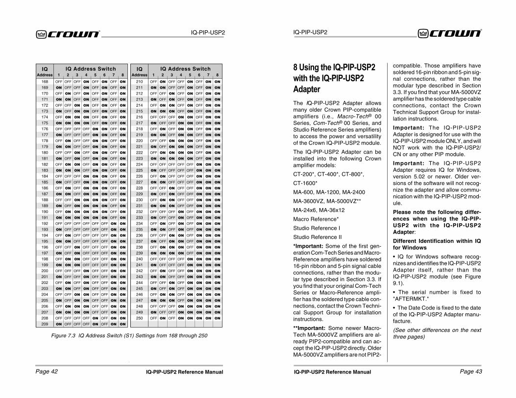
Figure 7.3 IQ Address Switch (S1) Settings from 168 through 250
8 Using the IQ-PIP-USP2with the IQ-PIP-USP2AdapterThe IQ-PIP-USP2 Adapter allowsmany older Crown PIP-compatibleamplifiers (i.e., Macro-Tech® 00Series, Com-Tech® 00 Series, andStudio Reference Series amplifiers)to access the power and versatilityof the Crown IQ-PIP-USP2 module.
The IQ-PIP-USP2 Adapter can beinstalled into the following Crownamplifier models:
CT-200*, CT-400*, CT-800*,
CT-1600*
MA-600, MA-1200, MA-2400
MA-3600VZ, MA-5000VZ**
MA-24x6, MA-36x12
Macro Reference*
Studio Reference I
Studio Reference II
*Important: Some of the first gen-eration Com-Tech Series and Macro-Reference amplifiers have soldered16-pin ribbon and 5-pin signal cableconnections, rather than the modu-lar type described in Section 3.3. Ifyou find that your original Com-TechSeries or Macro-Reference ampli-fier has the soldered type cable con-nections, contact the Crown Techni-cal Support Group for installationinstructions.
**Important: Some newer Macro-Tech MA-5000VZ amplifiers are al-ready PIP2-compatible and can ac-cept the IQ-PIP-USP2 directly. OlderMA-5000VZ amplifiers are not PIP2-
compatible. Those amplifiers havesoldered 16-pin ribbon and 5-pin sig-nal connections, rather than themodular type described in Section3.3. If you find that your MA-5000VZamplifier has the soldered type cableconnections, contact the CrownTechnical Support Group for instal-lation instructions.
Important: The IQ-PIP-USP2Adapter is designed for use with theIQ-PIP-USP2 module ONLY, and willNOT work with the IQ-PIP-USP2/CN or any other PIP module.
Important: The IQ-PIP-USP2Adapter requires IQ for Windows,version 5.02 or newer. Older ver-sions of the software will not recog-nize the adapter and allow commu-nication with the IQ-PIP-USP2 mod-ule.
Please note the following differ-ences when using the IQ-PIP-USP2 with the IQ-PIP-USP2Adapter:
Different Identification within IQfor Windows
• IQ for Windows software recog-nizes and identifies the IQ-PIP-USP2Adapter itself, rather than theIQ-PIP-USP2 module (see Figure9.1).
• The serial number is fixed to"AFTERMKT."
• The Date Code is fixed to the dateof the IQ-PIP-USP2 Adapter manu-facture.
(See other differences on the nextthree pages)

IQ-PIP-USP2
Page 45IQ-PIP-USP2 Reference Manual
IQ-PIP-USP2
Page 44 IQ-PIP-USP2 Reference Manual
Figure 8.3 “Peak Voltage Limiter” BlockDisabled on “Signal Path” Tab
Figure 8.4 “Average Power Limiter”Block Disabled on “Signal Path” Tab
Figure 8.1 "General" Tab showingIdentification of IQ-PIP-USP2 Adapter
Peak Voltage and AveragePower Voltage Limiter
Peak Voltage and Average PowerLimiters are not available.
Figure 8.2 “Signal Path” Tabshowing Peak Voltage and Average
Power Limiters Disabled
IQ-PIP-USP2
Page 47IQ-PIP-USP2 Reference Manual
IQ-PIP-USP2
Page 46 IQ-PIP-USP2 Reference Manual
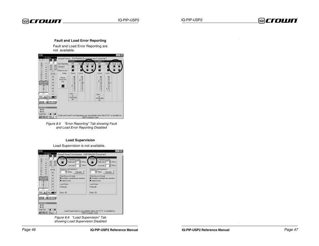
Fault and Load Error Reporting
Fault and Load Error Reporting arenot available.
Figure 8.5 “Error Reporting” Tab showing Faultand Load Error Reporting Disabled
Load Supervision
Load Supervision is not available.
Figure 8.6 “Load Supervision” Tabshowing Load Supervision Disabled

IQ-PIP-USP2
Page 49IQ-PIP-USP2 Reference Manual
IQ-PIP-USP2
Page 48 IQ-PIP-USP2 Reference Manual
8 Service8.1 Worldwide Service
Service may be obtained from anauthorized service center. (Contactyour local Crown/Amcron represen-tative or our office for a list of autho-rized service centers.) To obtainservice, simply present the bill ofsale as proof of purchase along withthe defective unit to an authorizedservice center. They will handle thenecessary paperwork and repair.
Remember to transport your unit inthe original factory pack.
8.2 US and Canada Service
Service may be obtained in one oftwo ways: from an authorized ser-vice center or from the factory. Youmay choose either. It is importantthat you have your copy of the bill ofsale as your proof of purchase.
8.2.1 Service at a US or CanadaService Center
This method usually saves the mosttime and effort. Simply present yourbill of sale along with the defectiveunit to an authorized service centerto obtain service. They will handlethe necessary paperwork and re-pair. Remember to transport the unitin the original factory pack. A list ofauthorized service centers in yourarea can be obtained from the Crownwebsite at www.crownaudio.com, orby calling Crown Factory Service.
8.2.2 Factory Service
To obtain factory service, fill out theservice information page found inthe back of this manual and send italong with your proof of purchase
and the defective unit to the Crownfactory.
For warranty service, we will pay forground shipping both ways in theUnited States. Contact Crown Fac-tory Service to obtain prepaid ship-ping labels prior to sending the unit.Or, if you prefer, you may prepay thecost of shipping, and Crown will re-imburse you. Send copies of theshipping receipts to Crown to re-ceive reimbursement.
Your repaired unit will be returnedvia UPS ground. Please contact us ifother arrangements are required.
8.2.3 Factory Service ShippingInstructions:
1. Before sending a Crown productto the factory for service, first callCrown Factory Service for a returnauthorization (RA) number.
2. Be sure to fill out the serviceinformation form that follows andenclose it with your shipment, eitherinside the box or in a packing slipenvelope securely attached to theoutside of the shipping carton. Donot send the service information formseparately. If you are sending theunit from a Shipping Center, we rec-ommend taping the form to the prod-uct. We also recommend recordingthe serial number and model beforeshipping for your reference.
3. To ensure the safe transportationof your unit to the factory, ship it in anoriginal factory packing container.
If you don't have the original carton,you may obtain a product servicefoam-in-place shipping pack fromCrown Factory Service at the num-ber listed below. For non-warrantyservice, you may also provide yourown shipping pack, however we stillrecommend using a Crown suppliedshipping container. Minimum recom-mended requirements for materialsare as follows: 275 P.S.I. burst testDouble-Wall carton that allows for 2-inch solid Styrofoam on all six sidesof unit or 3 inches of plastic bubblewrap on all six sides of unit; securelyseal the package with an adequatecarton sealing tape. Do not use lightboxes or "peanuts." Damage causedby poor packing cannot be coveredunder warranty.
4. Do not ship the unit in any kind ofcabinet (wood or metal). Ignoringthis warning may result in extensivedamage to the unit and the cabinet.Accessories are not needed-do notsend the product documentation,cables and other hardware.
If you have any questions, pleasecontact Crown Factory Service.
Crown Factory Service1718 W. Mishawaka Rd.
Elkhart, Indiana 46517 U.S.A.
Telephone: 574-294-8200800-342-6939 (North America,Puerto Rico, and Virgin Islands
only)
Facsimile:574-294-8301 (Technical Support)
574-294-8124 (Factory Service)
Internet:http://www.crownaudio.com

12/01
WORLDWIDE EXCEPT USA & CANADASUMMARY OF WARRANTY
Crown International, 1718 West Mishawaka Road, Elkhart, Indiana 46517-4095U.S.A. warrants to you, the ORIGINAL PURCHASER and ANY SUBSEQUENTOWNER of each NEW Crown1 product, for a period of three (3) years from the dateof purchase by the original purchaser (the “warranty period”) that the new Crownproduct is free of defects in materials and workmanship, and we further warrant thenew Crown product regardless of the reason for failure, except as excluded in thisCrown Warranty.1 Note: If your unit bears the name “Amcron,” please substitute it for the name “Crown” inthis warranty.
ITEMS EXCLUDED FROM THIS CROWN WARRANTYThis Crown Warranty is in effect only for failure of a new Crown product which occurredwithin the Warranty Period. It does not cover any product which has been damagedbecause of any intentional misuse, accident, negligence, or loss which is covered underany of your insurance contracts. This Crown Warranty also does not extend to the newCrown product if the serial number has been defaced, altered, or removed.
WHAT THE WARRANTOR WILL DOWe will remedy any defect, regardless of the reason for failure (except as excluded), byrepair, replacement, or refund. We may not elect refund unless you agree, or unless weare unable to provide replacement, and repair is not practical or cannot be timely made.If a refund is elected, then you must make the defective or malfunctioning productavailable to us free and clear of all liens or other encumbrances. The refund will be equalto the actual purchase price, not including interest, insurance, closing costs, and otherfinance charges less a reasonable depreciation on the product from the date of originalpurchase. Warranty work can only be performed at our authorized service centers. Wewill remedy the defect and ship the product from the service center within a reasonabletime after receipt of the defective product at our authorized service center.
HOW TO OBTAIN WARRANTY SERVlCEYou must notify us of your need for warranty service within the warranty period. Allcomponents must be shipped in a factory pack. Corrective action will be taken within areasonable time of the date of receipt of the defective product by our authorized servicecenter. If the repairs made by our authorized service center are not satisfactory, notify ourauthorized service center immediately.
DISCLAIMER OF CONSEQUENTIAL & INCIDENTAL DAMAGESYOU ARE NOT ENTITLED TO RECOVER FROM US ANY INCIDENTAL DAMAGESRESULTING FROM ANY DEFECT IN THE NEW CROWN PRODUCT. THIS INCLUDESANY DAMAGE TO ANOTHER PRODUCT OR PRODUCTS RESULTING FROM SUCHA DEFECT.
WARRANTY ALTERATIONSNo person has the authority to enlarge, amend, or modify this Crown Warranty. ThisCrown Warranty is not extended by the length of time which you are deprived of the useof the new Crown product. Repairs and replacement parts provided under the terms ofthis Crown Warranty shall carry only the unexpired portion of this Crown Warranty.
DESIGN CHANGESWe reserve the right to change the design of any product from time to time without noticeand with no obligation to make corresponding changes in products previouslymanufactured.
LEGAL REMEDIES OF PURCHASERNo action to enforce this Crown Warranty shall be commenced later than ninety (90) daysafter expiration of the warranty period.
THIS STATEMENT OF WARRANTY SUPERSEDES ANY OTHERSCONTAINED IN THIS MANUAL FOR CROWN PRODUCTS.
TH
RE
E Y
EA
RFU
LL W
AR
RA
NT
YYEAR3UNITED STATES & CANADA
SUMMARY OF WARRANTYCrown International, 1718 West Mishawaka Road, Elkhart, Indiana 46517-4095 U.S.A.warrants to you, the ORIGINAL PURCHASER and ANY SUBSEQUENT OWNER ofeach NEW Crown product, for a period of three (3) years from the date of purchase bythe original purchaser (the “warranty period”) that the new Crown product is free ofdefects in materials and workmanship. We further warrant the new Crown productregardless of the reason for failure, except as excluded in this Warranty.
ITEMS EXCLUDED FROM THIS CROWN WARRANTYThis Crown Warranty is in effect only for failure of a new Crown product which occurredwithin the Warranty Period. It does not cover any product which has been damagedbecause of any intentional misuse, accident, negligence, or loss which is covered underany of your insurance contracts. This Crown Warranty also does not extend to the newCrown product if the serial number has been defaced, altered, or removed.
WHAT THE WARRANTOR WILL DOWe will remedy any defect, regardless of the reason for failure (except as excluded), byrepair, replacement, or refund. We may not elect refund unless you agree, or unless weare unable to provide replacement, and repair is not practical or cannot be timely made.If a refund is elected, then you must make the defective or malfunctioning productavailable to us free and clear of all liens or other encumbrances. The refund will be equalto the actual purchase price, not including interest, insurance, closing costs, and otherfinance charges less a reasonable depreciation on the product from the date of originalpurchase. Warranty work can only be performed at our authorized service centers or atthe factory. Warranty work for some products can only be performed at our factory. Wewill remedy the defect and ship the product from the service center or our factory withina reasonable time after receipt of the defective product at our authorized service centeror our factory. All expenses in remedying the defect, including surface shipping costs inthe United States, will be borne by us. (You must bear the expense of shipping the productbetween any foreign country and the port of entry in the United States and all taxes,duties, and other customs fees for such foreign shipments.)
HOW TO OBTAIN WARRANTY SERVICEYou must notify us of your need for warranty service within the warranty period. Allcomponents must be shipped in a factory pack, which, if needed, may be obtained fromus free of charge. Corrective action will be taken within a reasonable time of the date ofreceipt of the defective product by us or our authorized service center. If the repairs madeby us or our authorized service center are not satisfactory, notify us or our authorizedservice center immediately.
DISCLAIMER OF CONSEQUENTIAL & INCIDENTAL DAMAGESYOU ARE NOT ENTITLED TO RECOVER FROM US ANY INCIDENTAL DAMAGESRESULTING FROM ANY DEFECT IN THE NEW CROWN PRODUCT. THIS INCLUDESANY DAMAGE TO ANOTHER PRODUCT OR PRODUCTS RESULTING FROM SUCHA DEFECT. SOME STATES DO NOT ALLOW THE EXCLUSION OR LIMITATIONS OFINCIDENTAL OR CONSEQUENTIAL DAMAGES, SO THE ABOVE LIMITATION OREXCLUSION MAY NOT APPLY TO YOU.
WARRANTY ALTERATIONSNo person has the authority to enlarge, amend, or modify this Crown Warranty. ThisCrown Warranty is not extended by the length of time which you are deprived of the useof the new Crown product. Repairs and replacement parts provided under the terms ofthis Crown Warranty shall carry only the unexpired portion of this Crown Warranty.
DESIGN CHANGESWe reserve the right to change the design of any product from time to time without noticeand with no obligation to make corresponding changes in products previouslymanufactured.
LEGAL REMEDIES OF PURCHASERTHIS CROWN WARRANTY GIVES YOU SPECIFIC LEGAL RIGHTS, YOU MAY ALSOHAVE OTHER RIGHTS WHICH VARY FROM STATE TO STATE. No action to enforce thisCrown Warranty shall be commenced later than ninety (90) days after expiration of thewarranty period.
THIS STATEMENT OF WARRANTY SUPERSEDES ANY OTHERSCONTAINED IN THIS MANUAL FOR CROWN PRODUCTS.
7/01
YEAR3
TH
RE
E Y
EA
RFU
LL W
AR
RA
NT
Y

Crown Factory Service InformationShipping Address: Crown Customer Service,
1718 W. Mishawaka Rd., Elkhart, IN U.S.A. 46517Phone: 1-800-342-6939 or 1-574-294-8200 Fax: 1-574-294-8124
Owner’s Name: __________________________________________________________Shipping Address: _______________________________________________________Phone Number: _______________________ Fax Number: ___________________Model: _______________________________ Serial Number: _________________
Purchase Date: __________________________________________________________
NATURE OF PROBLEM(Be sure to describe the conditions that existed when the
problem occurred and what attempts were made to correct it.)
_______________________________________________________________________
_______________________________________________________________________
_______________________________________________________________________
_______________________________________________________________________
_______________________________________________________________________
Other equipment in your system: __________________________________________
_______________________________________________________________________
_______________________________________________________________________
_______________________________________________________________________
_______________________________________________________________________
If warranty has expired, payment will be:❏❏❏❏❏ Cash/Check ❏❏❏❏❏ VISA ❏❏❏❏❏ MasterCard ❏❏❏❏❏ C.O.D. ❏ ❏ ❏ ❏ ❏ P.O. for Crown Dealer
Card Number:___________________________
Exp. Date: __________ Signature:____________________________
ENCLOSE THIS PORTION WITH THE UNIT.DO NOT MAIL SEPARATELY.