pipe installation deldot - cpb-us-w2.wpmucdn.com · installation procedure backfill testing rates...
TRANSCRIPT

1
Understanding the installation, specification, design requirements and material differences
for pipe systems
Proper Pipe Installation Practices
Proper Pipe Installation Practices
Agenda
Basic Pipe & Soil Concepts
Trench Fundamentals
Installation Procedure
Backfill Testing Rates
Expected Service Life/Benefits
• A well installed pipe should stay in service 50 to 100 years with little or no repair.
• DelDOT states 75 years for higher functional classification roads (SLI), 50 years for lower functional classification roads (SLII), 25 years for commercial/multi-family entrances (SLIII) and 15 years for residential entrances (SLIV).
PROPER INSTALLATION BENEFITS
•Essential to Pavement Performance
•Increases Bearing Capacity
•Increases Service Life
•Lowers Maintenance Cost

2
Fundamentals and Installation of Drainage Pipe
Factors Contributing to Successful Performance 1. Hydraulic Characteristics and Capacity
2. Structural Capacity
(Cover, Loads)
3. Environment Conditions (pH of soil and water)
(Soil Resistivity) (Abrasion due to sand and/or gravel)
(Standing Water)
(Metal, HDPE and RCP)
(RCP)
PIPE TERMINOLOGY
What 2 functions must an underground pipe provide?
Conduit
Structure
3
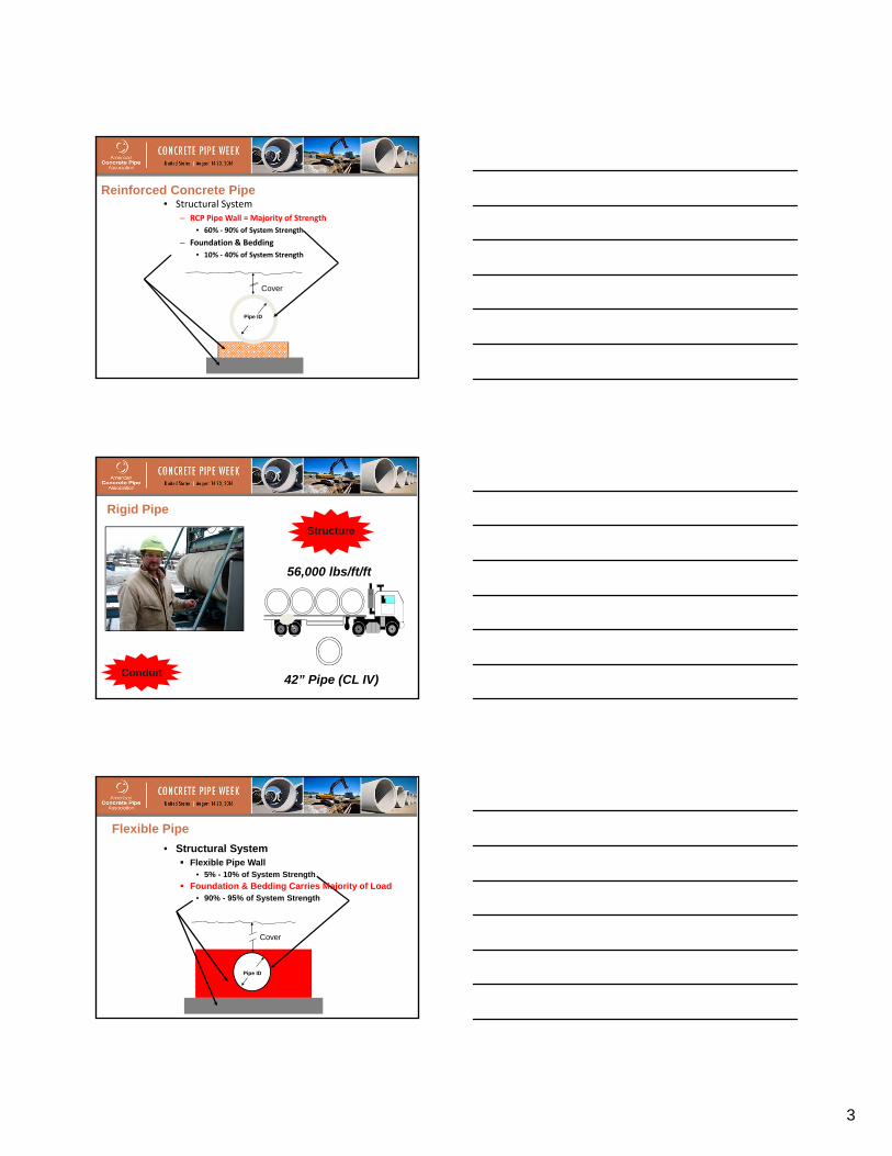
• Structural System
– RCP Pipe Wall = Majority of Strength
• 60% ‐ 90% of System Strength
– Foundation & Bedding
• 10% ‐ 40% of System Strength
Cover
Pipe ID
Reinforced Concrete Pipe
Structure
Rigid Pipe
Conduit 42” Pipe (CL IV)
56,000 lbs/ft/ft
Cover
Pipe ID
• Structural System Flexible Pipe Wall
• 5% - 10% of System Strength
Foundation & Bedding Carries Majority of Load • 90% - 95% of System Strength
Flexible Pipe

4
Flexible Installation
Construction Loading • Culverts are generally designed for the
loads they must carry after construction is completed. Construction loads often exceed design loads. These heavy loads can cause considerable damage in flexible pipes and can cause D-load cracking in rigid pipes.
• Additional temporary fill is needed to protect the pipe from construction loads.

5
Minimum Cover
Proper Cover?
Pipe Installation/Construction Checklist
Proper Installation Basic Requirements:
Pipe Material in Good Condition from Delivery to Final Installation
Compaction Backfill Material
Proper Installation Procedures Inspection During Installation
Post Installation Inspection per DelDOT Manual

6
1. Metal Pipe
• Gauge: 12, 14, 16
• Corrugation: 2 2/3” x ½”; 3” x 1”
2. Reinforced Concrete Pipe
• Class III, IV, or V
3. HDPE Pipe
• Meets AASHTO
Verifying Pipe
Pipe Storage
• Out of the way
• Stacked and chocked
• Do not stack on bells
Pipe Delivery/Handling
Pipe Delivery Communicate with Dispatcher
Proper Placement at Site Protect People/Pipe (Safety)

7
Pipe Handling Nesting (Safety)
Proper Sling Placement Protect People/Pipe (Safety)
Nested
Pipe Delivery/Handling
Fundamentals and Installation of Drainage Pipe
Trench Fundamentals
Bedding – 6” (min. loose Sand or type C Borrow)
Foundation
Varies*
Springline
Final Backfill Trench Terminology
Borrow Type C subsection 209.04
Below roadway or shoulders
95% or more max. density

8
Foundation
Trench/Pipe Terminology
Foundation
Trench/Pipe Terminology
Pipe Bedding/Backfill
DelDOT

9
Soil Properties
What three major soil properties come into play when installing a pipeline?
1. Composition
2. Gradation
3. Compaction
Composition
• Soil is an aggregate of loose mineral and organic particles.
• Rock exhibits strong and permanent
cohesive forces between mineral particles.
• Soil’s primary components are:
• Gravel • Sand • Silt • Clay
Well-graded soil has all sizes of material present from the No. 4 sieve to the No. 200 sieve.
Poorly graded soil may be uniformed-graded or gap-graded.
Well graded
Uniformly graded
Gap graded
Gradation

10
Compaction • Compaction is the densification of soil by the reduction of air
in the soil voids. • More difficult for water to migrate • Reduce subsequent settling under loading • The degree of compaction is measured in dry unit weight (dry
density). • Increase shear strength of soil
• Factors That Affect Compaction: • Water content of the soil • Type of Soil • Compactive effort
• lift thickness, number of roller passes, weight of the roller
• The type of compaction equipment • smooth drum, sheepsfoot, pneumatic tire, vibrating
plate, vibratory or static, etc • The speed of application • Compactive energy
Compaction
Fundamentals and Installation of Drainage Pipe
Installation Procedures

11
Trench Embankment
Tunnel
Installation Methods - Embankment/Trench/Jacking
There is NO Perfect Pipe
All pipes bring certain strengths and weaknesses.
Good designers/installers must accommodate for strengths that best benefit the project, while making sure the weaknesses don’t jump up and bite you.
Careful attention to construction details such as pipe bedding, backfill material, compaction and trench width are vital.
Poor compaction or poor quality backfill around culverts will result in uneven settlement and structural distress of the culvert which directly effects the long term performance of the pipe system.
Installation is Key
FLEXIBLE PIPE INSTALLATION

12
RCP INSTALLATION
INSTALLATION Safety
Pipe Delivery/Handling
Surveying
Drainage
Proper Eqpt./Material
Leadership
Pipe Installation Procedures 1. Locate Utilities 2. Excavate trench. 3. Explore Foundation 4. Place structural bedding material to grade. Do not compact. 5. Install pipe to grade. 6. Compact structural bedding outside the middle third of the pipe. 7. Place structural bedding in lifts. 8. Complete structural backfill operation by working from side to side of the pipe,
Foundation
Bedding
Do
Di
Hcover Final
Backfill
Springline
Do
/3 Middle
Third
In-situ Soil
13
Utilities
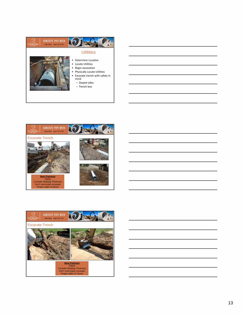
• Determine Location
• Locate Utilities
• Begin excavation
• Physically Locate Utilities
• Excavate trench with safety in mind
– Sloped sides
– Trench box
Excavate Trench
Best Practices Safety
Consider Bedding Thickness Don’t over/under excavate
Proper width of trench
Best Practices Safety
Consider Bedding Thickness Don’t over/under excavate
Proper width of Trench
Excavate Trench

14
Proper Trench Width
Yes
No
Compaction Equipment
Yes
Compaction Equipment
No
Trench Box
• Explore Foundation to determine the type and condition of the foundation
• Explore to a depth equal to ½” per foot of fill height or 8” (whichever is greater)
• Entrance Pipes of 12” to 30” diameter under 15’ of fill or less – no exploration is needed
• Stable Foundation must be provided to ensure proper line and grade is maintained
Pipe Foundation

15
Pipe Foundation Pipes and box culverts
Foundation
Crusher run aggregate size No. 25 or 26
----------------------------------
When standing water is in pipe foundation area, No. 57 stone can be
used as a backfill in the sub-foundation:
No. 57 stone MUST be capped with a minimum of 4” crusher run prior to placement of pipe or box culvert
Compaction testing on No. 57 stone is not required; seat stone in trench
Standard Installation
Bedding 6” loosely placed
Shaped 10% of outside Ø Graded to distribute load
Check Grade
Standard Installation
Bedding • Standard Drawing D-8
• Bedding:
– Class C Bedding • 6” Min. Loose Sand or Type C Borrow
– Class A Bedding • 6” minimum plus Imbed pipe in concrete 6” for pipes
smaller than 24”; 10” for pipes 24” to 60”; and for pipes larger than 60” see project details

16
• Ensure bedding follows grade level for bottom of pipe to ensure continuous support along barrel of pipe
• Uneven bedding creates uneven pipe invert and induces longitudinal stresses in pipe.
Bedding
Place Structural Bedding to Grade
Best Practices Loosely Placed
Rocky Foundation Requires More Take Your Time - Importation Step
Best Practices Loosely Placed
Rocky Foundation Requires More Take Your Time - Importation Step
Place Structural Bedding to Grade

17
Install Pipe to Grade
Best Practices Use Proper Equipment
Check Bedding Elevation/Grade Downstream to upstream (bell up)
Best Practices Keep Pipe off Bedding
Protect Joint from Damage Avoid Pushing Down to get Grade
Install Pipe to Grade
Lift Hole and Plug in Concrete Pipe

18
Joints (Joining Pipe Sections)
What Function Do Pipe Joints Perform?
1. Provide flexibility and resiliency for movement.
2. Provide for expansion and contraction.
3. Guard against leakage.
4. Connect like materials.
5. Transition between unlike materials.
6. Transmit or transfer load.
7. Reduce stress on the material or structural member.
8. Other???
What Function Do Pipe Joints Perform?

19
Joint Assembly
• Joining Pipe: • Begin at the downstream end (Bell faces upstream) • Ensure spigot and bell are clean and free of debris. • Liberally Lubricate spigot and bell with pipe lubricant. • Is Contractor aware of the maximum insertion angle? • Fully insert pipe. (Make a Mark on Outside of Pipe) • Moving pipe around after joining may cause pipe joint to work apart.
•Rigid pipe - properly fitted, sealed with rubber, preformed plastic, mastic gaskets
•Flexible Pipe - properly aligned and joined with approved coupling bands
CMP Joint Bands
Annular Giles Dimple
Joint Options for HDPE
• Gasketed Spigot & Bell Joint (ST or WT)
• Split Band Coupler is used for plain end pipe or joining pipes that have been field cut.
Split Band Coupler
Plain End Pipe
Standard Gasketed Joint

20
Joint Sealing Options for RCP
Rubber O-Ring
Profile Rubber Gaskets
Butyl Mastic & Profile Rubber Gaskets
Compact Structural Bedding (Outside Middle 1/3 of Pipe)
Best Practices Prevent Pipe from Shifting Compact in Lifts (6” to 4”)
Use Proper Compaction Eqpt
Standard Installation

21
Backfill Material
• Pipe – Borrow Type C for pipe trenches below the roadway or
shoulders, 95% or more of maximum density – Borrow Type C for pipe trenches other than below
roadway or shoulders, to a height 12” above top of pipe and remainder to depth shall be backfilled with existing material. 90% or more of the maximum density
– Place an initial backfill lift that does not exceed 12” of loose material or no higher than springline. Slice backfill into the haunches. Place lifts no greater than 8” loose material.
Pipe & Box Culvert Backfill
• Excavation must be wide enough to accommodate compaction equipment
• Simultaneously backfill on both sides
• Static roll until fill is 4 feet above top of pipe or box
• Rocks > 2” must be moved away from structures a minimum of 12”
Final Backfill 12” Min Cover
Absolute min 12” (except entrances 9”)
Standard Installation

22
Complete Structural Backfill
Best Practices Prevent Pipe from Shifting
Place in Lifts (8”) Use Proper Compaction Eqpt
Best Practices Alternate from One Side to Next Trench Width Allows Compaction
Proper Material for Backfill
Complete Structural Backfill
Additional Backfilling Considerations
• Allow 48” of cover where heavy construction equipment travels over pipe

23
Connections to Structures
Pipe openings in precast drainage units shall not exceed the outside cross sectional dimensions of the pipes by more than a total of 8 inches regardless of the placement of the pipe, their angles of intersection, or shapes of the pipes.
Pipe – Structure Connections
Pipe Connections Rigid to Rigid
Flexible Connections w/Flexible Pipe 8 inch (Maximum) Gap
Grouting/Booting
Pipe Connections Rigid to Rigid
Flexible Connections w/Flexible Pipe 8 inch (Maximum) Gap
Grouting/Booting
Pipe – Structure Connections

24
Proper Connection Material Rigid to Rigid
Flexible to Flexible Don’t Take Short-cuts
Pipe – Structure Connections
Best Practices Manhole Adapters:
A-Lok, Z-Lok, Kor-N-Seal
Pipe – Structure Connections
Proper Connection Material Rigid to Rigid
Flexible to Flexible Don’t Take Short-cuts
Pipe – Structure Connections
25
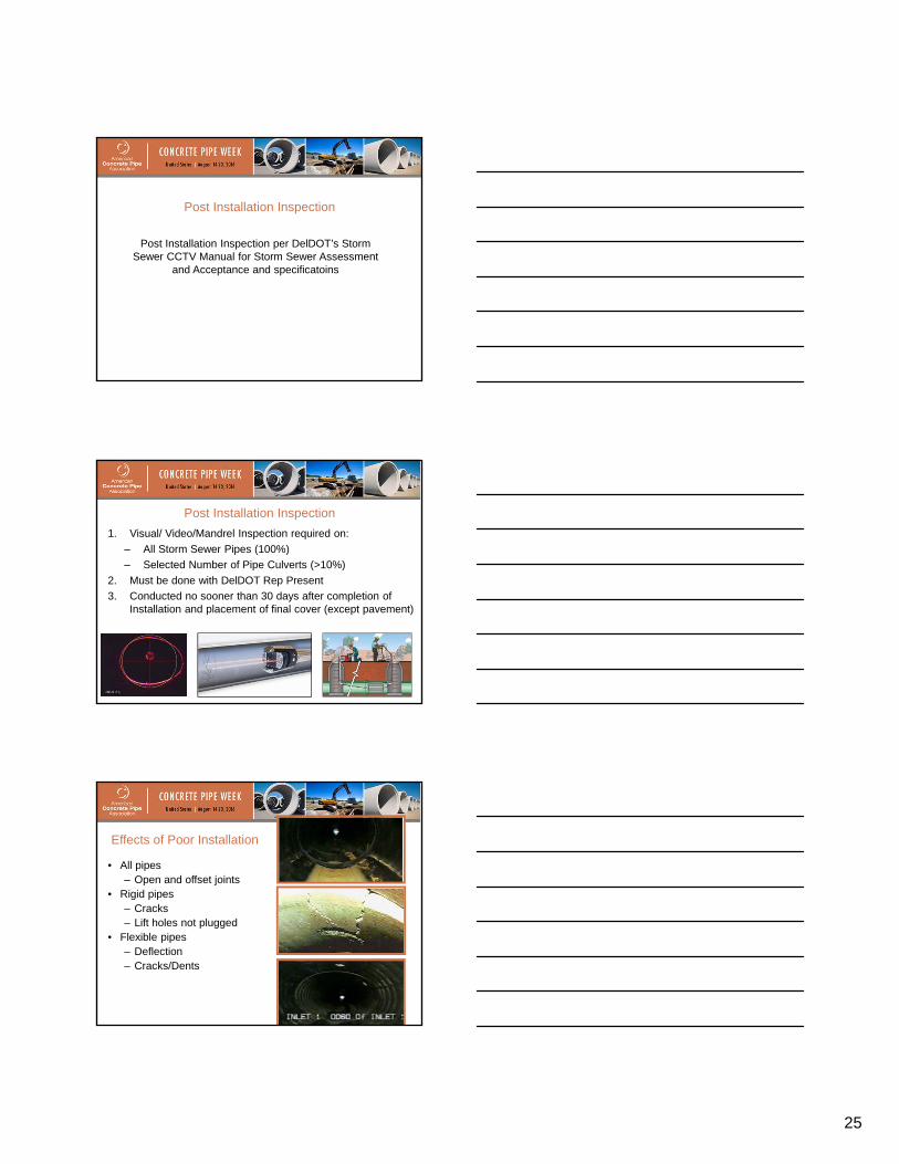
Post Installation Inspection per DelDOT’s Storm Sewer CCTV Manual for Storm Sewer Assessment
and Acceptance and specificatoins
Post Installation Inspection
1. Visual/ Video/Mandrel Inspection required on:
– All Storm Sewer Pipes (100%)
– Selected Number of Pipe Culverts (>10%)
2. Must be done with DelDOT Rep Present
3. Conducted no sooner than 30 days after completion of Installation and placement of final cover (except pavement)
Post Installation Inspection
Effects of Poor Installation
• All pipes – Open and offset joints
• Rigid pipes – Cracks – Lift holes not plugged
• Flexible pipes – Deflection – Cracks/Dents

26
• Poor Quality Joints
• Migration of fines
• Sinkholes
• Loss of pipe foundation
• Eventual pipe failure
Effects of Poor Installation
Defects Reinforced Concrete Pipe 1. Illegal brand
2. Misalignment (vertical and horizontal)
3. Spalls
4. Slabbing
5. Cracks greater than 0.1” in width
6. Cracks greater than 0.01” in width and showing efflorescence or differential settlement
7. Differential joint movement
8. Improper gasket placement
9. Joint leakage
10. Settlement
11. Joint separations exceeding manufacturer’s recomm.
a. 12‐36” 0.75”
b. 42” and larger 1.25”
c. All Elliptical 1.5”
Defects Metal Culverts 1. Illegal brand
2. Uneven laps
3. Deflection greater than 7.5%
4. Elliptical shaping (circular pipe only)
5. Misalignment (vertical and horizontal)
6. Ragged or diagonal sheared edges
7. Loose, unevenly lined or spaced rivets
8. Imperfectly formed rivet heads
9. Unfinished ends
10. Lack of rigidity
11. Bruised, scaled or broken protective coating
12. Dents or bends in the metal
13. Improperly seated bells/spigots
14. Bulging or hanging gaskets
15. Joint separations exceeding manufacturer’s recommendation or as follows:
a. 12-36” 0.75”
b. 42” and larger 1.25”
c. All Elliptical 1.5”
27
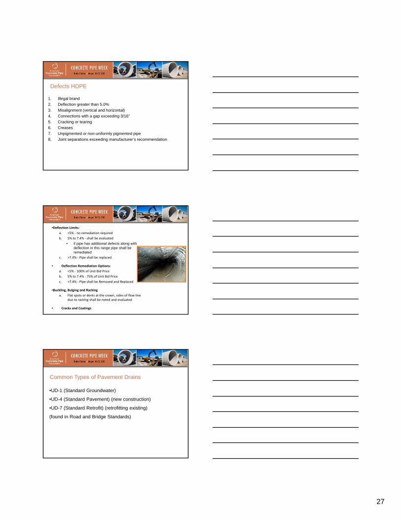
Defects HDPE
1. Illegal brand
2. Deflection greater than 5.0%
3. Misalignment (vertical and horizontal)
4. Connections with a gap exceeding 3/16”
5. Cracking or tearing
6. Creases
7. Unpigmented or non-uniformly pigmented pipe
8. Joint separations exceeding manufacturer’s recommendation
•Deflection Limits:
a. <5% ‐ no remediation required
b. 5% to 7.4% ‐ shall be evaluated
• if pipe has additional defects along with deflection in this range pipe shall be remediated
c. >7.4% ‐ Pipe shall be replaced
• Deflection Remediation Options:
a. <5% ‐ 100% of Unit Bid Price
b. 5% to 7.4% ‐ 75% of Unit Bid Price
c. >7.4% ‐ Pipe shall be Removed and Replaced
•Buckling, Bulging and Racking
a. Flat spots or dents at the crown, sides of flow line due to racking shall be noted and evaluated
• Cracks and Coatings
Common Types of Pavement Drains
•UD-1 (Standard Groundwater)
•UD-4 (Standard Pavement) (new construction)
•UD-7 (Standard Retrofit) (retrofitting existing)
(found in Road and Bridge Standards)

28
UD-4 Standard Pavement
UD-7 Standard Retrofit
Components Trench (.5 to 1% long slope)
Non-woven geotextile drainage fabric Perforated long pipe (35 psi min.) collector
Aggregate backfill (#8 or #57) Non-perforated smooth wall outlet pipe (35 psi)
An end-wall for outlet pipe protection
Pavement Drains
Pavement Drains
Pavement Drains Performance Intercept Collect
Discharge

29
General Underdrain Installation Guide 1. Excavate trench making sure walls are stable. 2. Remove any sloughed materials from trench 3. Excavated material picked up with conveyor and/or front end loader and removed from
site. 4. Minimum of 0.5 to 1.0% longitudinal slope 5. Open on as much trench as can be safely managed 6. Line trench with non-woven drainage fabric 7. Install long. perf. pipe at bottom of trench w/out bedding 8. Place 45 deg. elbow at end of run, connect longit. pipe to non-perforated outlet pipe to
discharge water. Drainage side 9. Connect outlet pipe to back of end-wall 10. Backfill trench with #8 or #57 aggregate asap nlt end of day. 11. Backfill depth is at least equal to diameter of pipe. 12. Backfill is usually placed loosely & heaped above finish level 13. Use vibratory place with welded foot to compact agg. Backfill 14. Fold drainage fabric to provide 100% overlap at top of trench 15. UD-4, Open Graded Drainage Layer placed on top of trench 16. UD-7, as asphalt cap is used to complete backfilling & provide the final surface is even with
shoulder. 17. Inspect once complete to ensure no areas are crushed, clogged or non-functioning.
Inspect per VTM-108.
Conclusion
• Storm Sewers and Culverts have a direct effect on Roads.
• The Inspectors level of commitment to requiring the Contractor to follow DelDOT Standards will have a direct effect on long term DelDOT Maintenance Costs and the long term Quality of Delaware Roads.
• 1. Before starting to dig what should be located?
Utilities
• 2. True or False. When moving concrete pipe you should pick it up by one end.
• False
• 3. What is maximum size rock to be placed no closer than 12 inches from pipe _____.
• 2”
• 4. What is the maximum backfill lift thickness?
• 8 inches loose (12” initial lift)
• 5. What is the maximum backfill lift thickness?
• 8 inches loose (12” initial lift)

30
• 6. Pipe openings in precast drainage structures shall not exceed the outside cross sectional dimensions of the pipe by more than
• 8 inches
• 7. The video inspection can be done after installation is complete.
• 30 days
• 8. The maximum allowed crack size of rigid pipe is .
• 0.1 inches.
• 9. The maximum deflection allowed for flexible pipe is .
• 5.0% for HDPE and 7.5% for CMP
• 10. What end of the pipe system do you start installation?
• downstream (bell pointed upstream)
• 11. What is the level of compaction required for pipe backfill?
• 95% under roadways and shoulders
• 12. What is the minimum amount of cover over pipe allowed for design loads?
• 12” minimum). 9” entrances (exception)
• 13. What is the minimum amount of cover over pipe to prevent damage from construction loads?
• 4 feet