pipe stress analysis with caesar ii
DESCRIPTION
Presentasi mengenai Pipe Stress Analysis, Code-code yang berhubungan, serta penggunaan software untuk keperluan PSA.TRANSCRIPT

7/17/2019 Pipe Stress Analysis With Caesar II
http://slidepdf.com/reader/full/pipe-stress-analysis-with-caesar-ii 1/60
I. PENDAHULUAN
Piping System adalah alat transportasi fluida dari satu titik ke titik lain yangpaling effisien dan umum digunakan.
Dalam setiap phase Detail Design (engineering), adalah sangat pentinguntuk dipastikan bahwa suatu sistem perpipaan akan aman biladioperasikan pada suatu pabrik / plant. Karena satu kegagalan saja dalamkomponen piping system dapat menyebabkan shut down pada plant/pabrik,
atau lebih buruknya lagi dapat menimbulkan masalah safety yang serius
bagi lingkungan/publik.
Setiap bagian dari sistem perpipaan harus diyakini (dicheck) aman sesuaidengan code standard / specification yang ada.
Pengecekan terhadap sistem perpipaan itu disebut Flexibility Analysis
atau Pipe Stress Analysis

7/17/2019 Pipe Stress Analysis With Caesar II
http://slidepdf.com/reader/full/pipe-stress-analysis-with-caesar-ii 2/60
Di dalam pekerjaan EPC dimanakah posisiPipe Stress Engineer ?

7/17/2019 Pipe Stress Analysis With Caesar II
http://slidepdf.com/reader/full/pipe-stress-analysis-with-caesar-ii 3/60
Sebuah Sistem Perpipaan didesain dalam beberapa tahapan-tahapan dan
dilakukan oleh beberapa Disiplin Engineering yang berbeda, yaitu :
Proses Engineer
Bertugas dalam keseluruhan proses yang akan dijalankan dalam suatupabrik, seperti menentukan flow path (jenis aliran), jumlah/quantity sesuaidengan kapasitas yang diinginkan, membuat Proses Flow Diagram,menentukan kondisi operasi (pressure dan temperature), memilih material
yang sesuai, equipment sizing, membuat line list, dan P&ID etc.
Piping Material
Bertugas membuat material specification and classification berdasarkan
proses requirement, termasuk didalamnya pipe, valve, flange and fittingsmaterial, menghitung pipe wall thickness dan menentukan corrossionallowance, menyiapkan MTO (Material Take Off), pipe accessories datasheet etc.

7/17/2019 Pipe Stress Analysis With Caesar II
http://slidepdf.com/reader/full/pipe-stress-analysis-with-caesar-ii 4/60
Piping Design
Berkoordinasi dengan disiplin engineering lain, piping designer harusmemahami overall plant layout, melakukan study rute pipa (piping
routing), menentukan letak pipe rack, merealisasikan layout pipa hinggaterkoneksi dari satu titik ke titik lain , menentukan (preliminary) lokasisupport berdasarkan company prosedure, membuat 3D modeling danIsometric Drawing yang akan digunakan untuk stress check, etc.
Pipe Stress
Tugas dan tanggung jawab dari Pipe Stress Engineer dapatdideskripsikan dalam gambar sebagai berikut :

7/17/2019 Pipe Stress Analysis With Caesar II
http://slidepdf.com/reader/full/pipe-stress-analysis-with-caesar-ii 5/60

7/17/2019 Pipe Stress Analysis With Caesar II
http://slidepdf.com/reader/full/pipe-stress-analysis-with-caesar-ii 6/60
Pipe Stress Analysis berfungsi untuk menganalisa Sistem Perpipaan agar Sistem
Perpipaan yang dirancang, memenuhi persyaratan-persyaratan diantaranya sebagai
berikut:
Tegangan (stress) yang terjadi pada material pipa tidak berlebih (tidak over stress).
Routing Pipa mempunyai flexibitas yang cukup untuk mengakomodasi terjadinya ekspansi thermal,
kontraksi, & movement support.
Routing Pipa mempunyai rigiditas dan support yang cukup untuk menahan beban pipa, fluida,
insulation, beserta material-material lain yang terpasang pada pipa.
Displacement (horizontal dan vertical) masih dalam batas-batas yang diberikan oleh spec.
Nozzle Loads (Nozzle Recation Force & Moment) on Equipment (Static or Rotating) memenuhi
allowable loads yang disyaratkan.
Reaction Force & Moment pada Supports tidak berlebih.
Natural Frequency system di atas batas aman tertentu (>5Hz, atau >6Hz, atau >8Hz as per project
spec) untuk pipa dengan Two Phase Flow.
II. TUJUAN PIPE STRESS ANALYSIS

7/17/2019 Pipe Stress Analysis With Caesar II
http://slidepdf.com/reader/full/pipe-stress-analysis-with-caesar-ii 7/60
III. PHILOSOPHY of FLEXIBILITY
Fenomena Thermal Expansion adalah sbb:
Apabila suatu pipa (logam) dipanaskan, pipa akan memuai (memanjang).Jika ujung-ujung pipa tersebut dipegang, pipa tidak akan dapat memuai.
Sebagai kompensasi dari tidak dapat memuainya pipa tersebut akanmengakibatkan: kenaikan Internal Stress dipipa, serta Gaya/Moment padabagian pipa yang dipegang. (See Fig II.1 & 2)
Yang akan menjadi masalah adalah: Apakah Internal Stress dipipa masih dibawah Allowable Stress? Jika yang memegang ujung-ujung pipa adalahnozzle dari equipment, Apakah Gaya/ Moment yang terjadi masih dibawah yang diizinkan Vendor? Karena dalam kasus ini yang di analisaadalah stress yang terjadi, maka disebut “Pipe Stress Analysis”.

7/17/2019 Pipe Stress Analysis With Caesar II
http://slidepdf.com/reader/full/pipe-stress-analysis-with-caesar-ii 8/60
III.1 Pipe Characteristic
L0
∆L1
L1 = L0 + ∆L1
L0 = L0 - ∆L2 ∆L2
T1
T2 ( T 2 > T 1 )
T3 ( T 3 < T 1 )
(Gambar. III.1)
Expansion
Normal
Contraction
F1 F1F= Reaction Force
a)
b)
c)
d)

7/17/2019 Pipe Stress Analysis With Caesar II
http://slidepdf.com/reader/full/pipe-stress-analysis-with-caesar-ii 9/60
Penjelasan :
Pada gambar III.1(a) diatas menunjukkan kondisi dimanasalah satu ujung pipa Fix dan salah satu ujung lainnya Free,
sehingga pipa dengan bebas mengalami expansi denganbesaran , dalam kondisi seperti ini tidak adaforce ataupun stress akibat thermal expansi yang terjadi didalam sistem.
Akan tetapi pada kondisi (d) dimana kedua ujung pipa dianchor (fix), maka akan timbul force pada anchor sebesarforce yang dibutuhkan untuk menekan kembali pipa yang
terekspansi kembali ke posisi semula (original posistion).

7/17/2019 Pipe Stress Analysis With Caesar II
http://slidepdf.com/reader/full/pipe-stress-analysis-with-caesar-ii 10/60
Dimana,
E = Modulus Elastisity
S = Axial Stress
A = Cross-section Area
∂ = Coefficient Thermal Expansion

7/17/2019 Pipe Stress Analysis With Caesar II
http://slidepdf.com/reader/full/pipe-stress-analysis-with-caesar-ii 11/60
III.2 Method of Providing Flexibility
Ada dua cara yang dapat dilakukan untuk menambahflexibility pipa yaitu dengan flexible joint method (includingexpansion joint, flexible hose etc. dan pipe loop.
Dari gambar (III.1 d), pada pipa lurus diatas, kita tahu bahwaada thermal expansion force dan stress yang sangat besarterjadi pada anchor (fix) point. Untuk mengurangi force dan
stress yang terjadi di kedua fix point tersebut, perluditambahkan flexibility pipa yaitu dengan menambahkanexpansion loop. Loop tersebut akan mengabsorb thermalforce dan stress, semakin panjang leg loop yang diberikan
akan semakin besar pula thermal force & stress yang di-absorb.

7/17/2019 Pipe Stress Analysis With Caesar II
http://slidepdf.com/reader/full/pipe-stress-analysis-with-caesar-ii 12/60
(Gambar. III.2.1.a)

7/17/2019 Pipe Stress Analysis With Caesar II
http://slidepdf.com/reader/full/pipe-stress-analysis-with-caesar-ii 13/60
(Gambar. III.2.1.b)

7/17/2019 Pipe Stress Analysis With Caesar II
http://slidepdf.com/reader/full/pipe-stress-analysis-with-caesar-ii 14/60
(Gambar. III.2.1.b)
Untuk menentukan panjang leg dapat dilakukan denganperhitungan berikut :
…………….( Peng LC Chapter 3)E = Modulus Elasticity (Psi)
S = Bending Stress (Psi)
∆ = Thermal Expansion (in or mm)
D = Pipe Diameter ( in or mm )

7/17/2019 Pipe Stress Analysis With Caesar II
http://slidepdf.com/reader/full/pipe-stress-analysis-with-caesar-ii 15/60
III.3 Stress and Strain
Yield Strength : batas tegangan maximum dimana material terdeformasi plastis (material ditarik tidak bisa kembali ke bentuk semula)
Setiap material mempunyaiTegangan Ijin (Allowable Stress) yang tidak boleh terlampaui
(Allowable stress ada di tabel A1 dari ASME B31.3)
Nilai Allowable stress menurut ASME B31.3 berkisar 62.5% dariYield Stress. Besarnya yield
strength menurun dengan naiknya temperatur, sehingga Allowable stress juga turun mengikuti
turunnya temperatur.
Ultimate tensile strength : maksimum teganganyg bisa ditahan material sebelum material patah

7/17/2019 Pipe Stress Analysis With Caesar II
http://slidepdf.com/reader/full/pipe-stress-analysis-with-caesar-ii 16/60
IV. CHECKING GRADE for CRITICAL LINE (1)
Flexibility analysis adalah pekerjaan yang cukup menyita manhours,apabila seluruh pipa dicheck stress analysisnya, dan akanmemperlambat schedule project.
Untuk itu berdasarkan sejarah system perpipaan sebelumnya, makadipilih pipa-pipa yang kritis saja yang perlu dilakukan stress analysis.Pemilihan ini diseleksi berdasarkan checking grade suatu project.
Checking grade adalah grafik pemilihan pipa-pipa kritis yang ditetapkanoleh client/ licensor/ main contractor pada suatu project. Pada grafik inigrade ditentukan berdasarkan variable “Pipe size” dan “temperature”.

7/17/2019 Pipe Stress Analysis With Caesar II
http://slidepdf.com/reader/full/pipe-stress-analysis-with-caesar-ii 17/60
Comprehensive analysis should be performed in accordance with the followingcriteria;
d X t ≧ 1000 d = diameter / NPS
t = Max. difference between base temperature and analysis temperature / °C Comprehensive analysis shall be also required in the following cases;
Lines above 100°C (differential temp between base temp. and analysis temp.), ifmade of non-ferrous materials
Lines above 50°C (differential temp between base temp. and analysis temp.), if
made of non-metallic materials NPS 3 and larger piping (150℃ temperature and over) connecting to rotating
equipment
NPS 3 and larger piping (150℃ temperature and over) connecting to low allowableload nozzle (air-fin coolers, etc.)
NPS 2 and larger piping connecting to large movement lines ( ≥40mm ) NPS 2 and larger piping (solar radiant temperature and over) for high rating lines (
≥900 lb ), and
Critical line also determine by table 4.1 and 4.2 bellow :
IV. CHECKING GRADE for CRITICAL LINE (2)

7/17/2019 Pipe Stress Analysis With Caesar II
http://slidepdf.com/reader/full/pipe-stress-analysis-with-caesar-ii 18/60
IV.1 Piping System Connected to Static Equipment
Table 4.1

7/17/2019 Pipe Stress Analysis With Caesar II
http://slidepdf.com/reader/full/pipe-stress-analysis-with-caesar-ii 19/60
IV.2 Piping System Connected to Rotating Equipment
Table 4.2

7/17/2019 Pipe Stress Analysis With Caesar II
http://slidepdf.com/reader/full/pipe-stress-analysis-with-caesar-ii 20/60
IV.3 Critical Line List Example
Table 4.3

7/17/2019 Pipe Stress Analysis With Caesar II
http://slidepdf.com/reader/full/pipe-stress-analysis-with-caesar-ii 21/60
V. BEBAN PADA PIPA ( PIPE LOADING )
Sustain Load
Beban yang muncul terus menerus dan berkesinambungan selama masa
operasi dari sistem perpipaan. Contoh: beban berat pipa sendiri, beban
internal pressure fluida.
Occassional Load
Beban yang muncul tidak berkesinambungan, atau munculnya tiba-tiba selama
masa operasi dari sistem perpipaan. Contoh: gaya angin, gaya gempa bumi.
Expansion Load
Beban yang muncul karena adanya perubahan displacement dari system
perpipaan yang bisa diakibatkan oleh thermal expansion dan perubahan letak
tumpuan.

7/17/2019 Pipe Stress Analysis With Caesar II
http://slidepdf.com/reader/full/pipe-stress-analysis-with-caesar-ii 22/60
VI. STRESS CATEGORIES Based on ASME B31.3(1)
Primary Stress
Adalah jenis stress yang ditimbulkan akibat Sustain Load. Stress kategori ini dikelompokkan dalam
stress yang berbahaya (hazardous type of stress).
Primary Stress terdiri atas komponen sebagai berikut :
Longitudinal Stress
Yaitu stress/tegangan yang terjadi akibat Tegangan Dalam (Axial Stress) + Tegangan
Tekanan Dalam (Internal Pressure Stress) + Tegangan Lentur (Bending Stress).

7/17/2019 Pipe Stress Analysis With Caesar II
http://slidepdf.com/reader/full/pipe-stress-analysis-with-caesar-ii 23/60

7/17/2019 Pipe Stress Analysis With Caesar II
http://slidepdf.com/reader/full/pipe-stress-analysis-with-caesar-ii 24/60

7/17/2019 Pipe Stress Analysis With Caesar II
http://slidepdf.com/reader/full/pipe-stress-analysis-with-caesar-ii 25/60
Stress Categories (2)
Secondary Stress
Adalah stress yang diakibatkan oleh thermal loads. Yaitu akibat temperature fluida yang
mengalir, yang menyebabkan pipa mengalami pemuaian atau pengkerutan (expansion or
contraction), dimana :
Sb = resultant bending stress,psi = [(IiMi)2 + (IoMo)2] / Z
St = Torsional stress ,psi = Mt / (2Z)

7/17/2019 Pipe Stress Analysis With Caesar II
http://slidepdf.com/reader/full/pipe-stress-analysis-with-caesar-ii 26/60
VII. ALLOWABLE STRESS LIMITATION
Berdasarkan ASME B31.3 limitasi dari masing-masing besaran pembebanan diatas adalah sbb:
Stress karena Sustained Load, limitasinya adalah :
SL < Sh, dimana :
Sh = Tegangan yang diijinkan pada suhu maksimum dari suatu material
Ketebalan dari pipa yang digunakan untuk menghitung SL haruslah merupakan
tebal nominal setelah dikurangi tebal lapisan korosi dan erosi yang diijinkan
Stress karena Occassional Load, limitasinya adalah :
Fax/A + Sb + Slp < k Sh , dimana nilai k = 1.33
Stress karena Thermal Load, limitasinya adalah :
SE < SA , dimana :
SE = (Sb2 + 4St
2)1/2
SA = Allowable displacement stress range = f [(1.25(Sc + Sh) – SL]

7/17/2019 Pipe Stress Analysis With Caesar II
http://slidepdf.com/reader/full/pipe-stress-analysis-with-caesar-ii 27/60
VII.1 Code Allowable Stress Comparison
LOAD CASE ASME B 31.3 ASME B 31.8 ASME B 31.4
For Restrained Pipe (as defined in Section 833.1):
< 0.9 ST
For Unrestrained Pipe (as defined in Section 833.1):
< 0.75 ST
Operating (OPE) No Allowable Limit < 0.9 ST < 0.9 (Syield)
Expansion (EXP) < f [ 1.25 (Sc+Sh) - SL ] < f [1.25 (SC + SH) – SL] < 0.72 (Syield)
Hydrotest (HYD) (Syield) < 0.9 ST < 0.9 (Syield)
For Restrained Pipe (as defined in Section 833.1):
< 0.9 ST
For Unrestrained Pipe (as defined in Section 833.1):< 0.75 ST
Sustain (SUS)
Occassional (OCC)
< Sh < (0.75) (Syield)
< k Sh < 0.8 (Syield)
Dimana ;
S or Syield = Specified Minimum Yield Stress
T = Temperature Derating Factor (see Table 841.116A of the B31.8 Code)
E = Weld Joint Factor

7/17/2019 Pipe Stress Analysis With Caesar II
http://slidepdf.com/reader/full/pipe-stress-analysis-with-caesar-ii 28/60
Abbreviation
SA = Allowable displacement stress range = f [(1.25(Sc + Sh) – SL]
Sb = resultant bending stress,psi = [(IiMi)2 + (IoMo)2] / Z
Mi = in-plane bending moment, in.lb
Mo = out-plane bending moment, in.lb
Ii = in-plane stress intensification factor (appendix B31.3)
Io = out-plane stress intensification factor (appendix B31.3)
St = Torsional stress ,psi = Mt / (2Z)
Mt = Torsional moment, in.lb
Sc = Basic allowable stress at minimum metal temperature
Sh = Basic allowable stress at maximum metal temperature
f = stress range reduction factor (table 302.2.5 of B31.3)

7/17/2019 Pipe Stress Analysis With Caesar II
http://slidepdf.com/reader/full/pipe-stress-analysis-with-caesar-ii 29/60
VIII.1 Menentukan Letak Support
Ada beberapa pertimbangan yang dibutuhkan dalam menentukanletak support yaitu :
1. Support Span ( jarak maximum antar support )
Basic condition untuk menentukan support span adalah sbb :
- Pipa dianggap lurus dengan kondisi batas (boundary condition) dari
pipe support span adalah fixed end pada kedua ujung pipa.
- Tidak mempertimbangkan thermal load, seismic load, dan wind load.
- Mempertimbangkan berat insulasi pada pipa.
VIII. SUPPORT SYSTEM

7/17/2019 Pipe Stress Analysis With Caesar II
http://slidepdf.com/reader/full/pipe-stress-analysis-with-caesar-ii 30/60

7/17/2019 Pipe Stress Analysis With Caesar II
http://slidepdf.com/reader/full/pipe-stress-analysis-with-caesar-ii 31/60
Abreviation :
Ld : pipe support span calculated by deflection criteria, m
Ls : pipe support span calculated by bending stress criteria, m
Lf : pipe support span calculated by natural frequency criteria, m
E : modulus elasticity, Pa Fmin : minimum natural frequency, Hz
I : moment inertia of area, m4
∆a : allowable pipe deflection, m w : total weight of pipe per unit length, Kg/m
Sh : allowable stress of pipe at hot temperature, Pa
Cs : correction factor for bending stress (Cs=1)
Cd : correction factor for deflection (Cd=1)

7/17/2019 Pipe Stress Analysis With Caesar II
http://slidepdf.com/reader/full/pipe-stress-analysis-with-caesar-ii 32/60
2. Pipe Support diletakkan sedekat mungkin dengan pusat berat(concentrate mass) seperti valve, flange, strainer dll.
3. Pipe Support diletakkan sedekat mungkin dengan nozzleequipment.
4. Pipe Support diletakkan dengan mempertimbangkan lokasicivil structure yang terdekat, jika pipa berada di ketinggian.
5. Pada pipa lurus panjang sebisa mungkin meletakkan pipesupport dengan jarak antar support (pipe span) yang sama.

7/17/2019 Pipe Stress Analysis With Caesar II
http://slidepdf.com/reader/full/pipe-stress-analysis-with-caesar-ii 33/60
IX. STATIC EQUIPMENT MODELING
Dalam pemodelan Computer Software, ada 2 metode yang bisa digunakan untuk
memodelkan Static Equipment ( vessel, tank, HE…etc.) yaitu dengan :
1. Initial Displacement
Yaitu perhitungan yang dilakukan untuk mengetahui pergeseran(displacement)
pipe/nozzle baik yang disebabkan oleh gravitasi maupun thermal expansi.
y
x
FS
Ly1
Lx2
Ly2
N2
N1
SS
Ly3
Lx3
N3
Horizontal Vessel
7/17/2019 Pipe Stress Analysis With Caesar II
http://slidepdf.com/reader/full/pipe-stress-analysis-with-caesar-ii 34/60
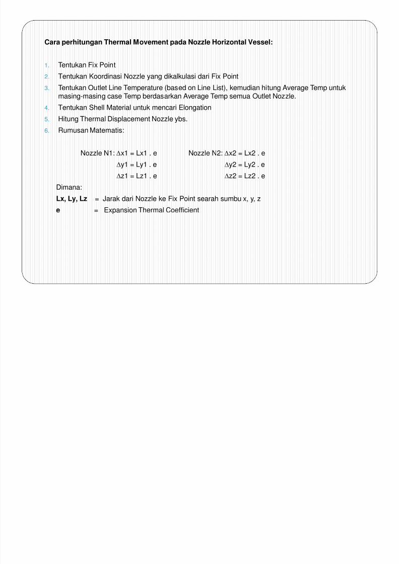
Cara perhitungan Thermal Movement pada Nozzle Horizontal Vessel:
1. Tentukan Fix Point
2. Tentukan Koordinasi Nozzle yang dikalkulasi dari Fix Point
3. Tentukan Outlet Line Temperature (based on Line List), kemudian hitung Average Temp untukmasing-masing case Temp berdasarkan Average Temp semua Outlet Nozzle.
4. Tentukan Shell Material untuk mencari Elongation
5. Hitung Thermal Displacement Nozzle ybs.
6. Rumusan Matematis:
Nozzle N1: ∆x1 = Lx1 . e Nozzle N2: ∆x2 = Lx2 . e
∆y1 = Ly1 . e ∆y2 = Ly2 . e∆z1 = Lz1 . e ∆z2 = Lz2 . e
Dimana:
Lx, Ly, Lz = Jarak dari Nozzle ke Fix Point searah sumbu x, y, z
e = Expansion Thermal Coefficient
y

7/17/2019 Pipe Stress Analysis With Caesar II
http://slidepdf.com/reader/full/pipe-stress-analysis-with-caesar-ii 35/60
Pr1
L
a 1
( - )
L a 2
L b
L t
Pr2
Pr4
N2
N4
N1
N5
N3
(T4+T5)
2
(T3+T4)
2
(T2+T3)
2
(T1+T2)
2
L c
L d
N9
N8
N7
N6
L 8
L 9
L 6
Neutral Level
L 7
Pada dasarnya perhitungan untuk Column sama dengan perhitungan untuk
Vertical Vessel, perbedaannya hanya pada asumsi temperatur tiap tray.
Dalam hal ini, setiap terjadi perbedaan Temp pada Outlet Nozzle, maka harus
dihitung Everage Temp untuk setiap segment perubahan Temp Outlet Nozzle
tsb.
∆Y1 = La1 . Ea ∆Y6 = L6 . ea
∆Y2 = La2 . Ea ∆Y7 = L7 . ea
∆Y3 = ∆Y2 + Lb . Eb ∆Y8 = ∆Y3 + L8 . ec
∆Y4 = ∆Y3 + Lc . Ec ∆Y9 = ∆Y4 + L9 . ed
∆Y5 = ∆Y4 + Ld . ed
∆Z1 = Lz1 . e1 = Pr1 . e1
∆Z2 = Lz2 . e2 = Pr2 . e2
∆Z3 = Lz3 . e3 = Pr3 . e3
∆Z4 = Lz4 . e4 = Pr4 . e4
∆Z5 = Lz5 . e5 = Pr5 . e5
∆Z6 = Lz6 . e6 = Pr6 . e6
dst……..
ea
eb
ec
ed
Column / Vertical Vessel
y
z
Dimana: Pr i = Nozzle Projection N i (jarak dari center line Vessel ke Flange Nozzle N i )ea,eb,ec,ed = Thermal Expansion (For Vertical Movement)e1,e2,e3,e4 = Thermal Expansion (For Lateral Movement)
β = Nozzle Orientation

7/17/2019 Pipe Stress Analysis With Caesar II
http://slidepdf.com/reader/full/pipe-stress-analysis-with-caesar-ii 36/60
2. Modeling as a Rigid
y
x
FS
Ly1
Lx1
Ly2
N2
N1
SS
C/L
Lx2
Lx3
ANC + CnodeANC + Cnode
Modeling Static Equipment di dalam computer software (Caesar II) juga dapat dilakukan dengan caramemodelkannya sebagai rigid, dimana rigid tersebut akan mengindikasikan besarnya ekspansithermal dari vessel tersebut.
Rigid W=0
Note : Cara pemodelan ke-2 ini biasanya yang lebih familiar digunakan karena selain lebih cepat dan mudah
juga lebih mendekati kondisi aktual jika dibandingkan dengan cara 1.

7/17/2019 Pipe Stress Analysis With Caesar II
http://slidepdf.com/reader/full/pipe-stress-analysis-with-caesar-ii 37/60
X. ROTATING EQUIPMENT MODELING
N2
N1
L y 1
Nozzle N1 : ∆x1 = Lx1 . e
∆y1 = Ly1 . e
∆z1 = Lz1 . e
Nozzle N2 : ∆x2 = Lx2 . e
∆y2 = Ly2 . e
∆z2 = Lz2 . e
Dimana:
e : Elongation/Thermal Expansion Coefficient of Pump Material (pada Average Temp Suction & DischargeNozzle) -- (See Attachment-I or ASME B31.3 table C-1)
Catatan:
Selain contoh di atas, masih banyak jenis pump yang lain dengan berbagai type arah nozzle Suction-Discharge. Panjang Lx, Ly, Lz harus tetap memperhatikan posisi nozzle terhadap Center of Pump.
1. Pump with Initial Displacement MethodeCenter of
PumpShaft
Centerline
PedestalCenterline

7/17/2019 Pipe Stress Analysis With Caesar II
http://slidepdf.com/reader/full/pipe-stress-analysis-with-caesar-ii 38/60
2. Pump Modeling as a Rigid Methode
N2
N1
L y 1
Center ofPump Shaft
Centerline
PedestalCenterline
Disch. Nozzle
ANC+Cnode
Suct. Nozzle
ANC+Cnode
Rigid w=0
O O O

7/17/2019 Pipe Stress Analysis With Caesar II
http://slidepdf.com/reader/full/pipe-stress-analysis-with-caesar-ii 39/60
Beban sebenarnya (aktual) yang terjadi pada nozzle berdasarkan hasil
analisis suatu sistem perpipaan dapat dikatakan aman (safe) apabila
beban tersebut dapat diterima (acceptable) atau berada pada zone
ambang batas beban yang diperkenankan (allowable) yang telah
ditetapkan baik oleh WRC-107/297 & ASME Sec. VIII untuk bejana
(vessel), API-650 untuk tangki, API-610 untuk pompa, API-617 untuk
kompresor maupun NEMA SM-23 untuk turbin dan kompressor atauallowable yang ditetapkan oleh pabrik pembuat/Vendor.
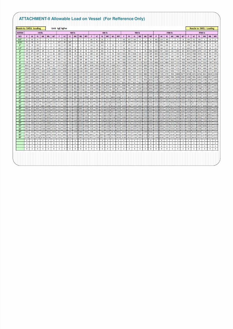
Ambang batas (allowable) yang dimaksud dibagi dalam dua kelompok,
yaitu batas untuk beban nozzle pada peralatan statik (see attachment-II)
dan beban nozzle untuk peralatan rotating (attachment-III).
XI. ALLOWABLE NOZZLE LOAD

7/17/2019 Pipe Stress Analysis With Caesar II
http://slidepdf.com/reader/full/pipe-stress-analysis-with-caesar-ii 40/60

7/17/2019 Pipe Stress Analysis With Caesar II
http://slidepdf.com/reader/full/pipe-stress-analysis-with-caesar-ii 41/60
ATTACHMENT-I Expansion Thermal Coefficient

7/17/2019 Pipe Stress Analysis With Caesar II
http://slidepdf.com/reader/full/pipe-stress-analysis-with-caesar-ii 42/60
ATTACHMENT-I Expansion Thermal Coefficient
ATTACHMENT-I Expansion Thermal Coefficient ( Cont’d )

7/17/2019 Pipe Stress Analysis With Caesar II
http://slidepdf.com/reader/full/pipe-stress-analysis-with-caesar-ii 43/60
ATTACHMENT I Expansion Thermal Coefficient ( Cont d )
ATTACHMENT-II Allowable Load on Vessel (For Refference Only)
7/17/2019 Pipe Stress Analysis With Caesar II
http://slidepdf.com/reader/full/pipe-stress-analysis-with-caesar-ii 44/60
ATTACHMENT-II Allowable Load on Vessel (For Refference Only)

7/17/2019 Pipe Stress Analysis With Caesar II
http://slidepdf.com/reader/full/pipe-stress-analysis-with-caesar-ii 45/60
ATTACHMENT-II Allowable Load on Pump (API 610)

7/17/2019 Pipe Stress Analysis With Caesar II
http://slidepdf.com/reader/full/pipe-stress-analysis-with-caesar-ii 46/60
ATTACHMENT-II Allowable Load on Pump (API 610)

7/17/2019 Pipe Stress Analysis With Caesar II
http://slidepdf.com/reader/full/pipe-stress-analysis-with-caesar-ii 47/60

7/17/2019 Pipe Stress Analysis With Caesar II
http://slidepdf.com/reader/full/pipe-stress-analysis-with-caesar-ii 48/60

7/17/2019 Pipe Stress Analysis With Caesar II
http://slidepdf.com/reader/full/pipe-stress-analysis-with-caesar-ii 49/60
GENERAL
Basically Dynamic Analysis in a Piping System divided into two
categories. First, Dynamic that considered as static load that
called Quasi Dynamic (Example : Pressure Safety Valve (PSV)
Load, Wind, Wave and Seismic Load). Secondly, Dynamic that
considered as a true Dymanic Load which it’s load is a kind of
time function ( W= F(t) ), for example : Flow Induce Vibration
(Two Phase Flow), and Pulsation & Vibration.
Each Dynamic load shall be considered when performing Piping
Stress Analysis because it’s have a potential source of failure for
a Piping System.

7/17/2019 Pipe Stress Analysis With Caesar II
http://slidepdf.com/reader/full/pipe-stress-analysis-with-caesar-ii 50/60
Macam-Macam Analisa Dynamic :
Two Phase Flow
Pulasation and Vibration
Hydraulic Transient (Water Hammer)
Pressure Relief Valve (PSV)
Acoustic Induce Vibration (AIV)
1. TWO PHASE FLOW

7/17/2019 Pipe Stress Analysis With Caesar II
http://slidepdf.com/reader/full/pipe-stress-analysis-with-caesar-ii 51/60
1. TWO PHASE FLOW
GasGas
Gas
Liquid
Flow
Fluid Force
A. Mechanism of Piping Vibration Due to Gas-Liquid Two Phase Flow
When flow in piping is gas-liquid two phase flow and flow pattern is intermittensuch as slug, plug and froth flows (intermitten flow), piping vibration is excited bycollision of liquid slugs at elbows or tees (see Figure-1)
Fig.1. Mechanism of Piping Vibration Due to Gas-LiquidTwo Phase Flow

7/17/2019 Pipe Stress Analysis With Caesar II
http://slidepdf.com/reader/full/pipe-stress-analysis-with-caesar-ii 52/60
The magnitude of fluid force acting on pipe elbows or tees by intermitten flow can be
estimated from momentum of liquid slug through elbows or tees of the piping. Inparticular the gas-liquid two phase piping severely vibrates in the following case :
a. Velocity of liquid slug is high and/or density of liquid slug is high.
b. Forced frequency by intermitten flow resonates with piping -
mechanical natural frequencies.
• Gas-Liquid two phase flow can be observe in the following lines :
a. Outlet line of heater
b. Outlet line of heat exchanger
c. Downstream line of pressure reducing device with flushing of fluid
d. Inlet line to reflux tower
B. Basic of Piping Design

7/17/2019 Pipe Stress Analysis With Caesar II
http://slidepdf.com/reader/full/pipe-stress-analysis-with-caesar-ii 53/60
p g g
The flow pattern, which cause two phase flow –induce vibration of piping, such as slug,
plug, and froth flow (intermitten flows), shall be prevented at the process design stage.
However, if it is unavoidable to design without intermitten flows. The following points shall
be considered at the piping design stage
The piping configuration of a two phase flow line shall be simply design and so that
the piping system doesn’t have the excess flexibility, as long as the thermal stress
design conform to allowable stress. For example, the length of piping and the
number of elbows should be minimized in order not to have excess flexibility.
Supports with sufficient strength and stifness shall be provided ti withstand the
exciting force at elbows. The direction of support shall conform to the vibration
direction.
Guide support should be provided at each vertical line.
A pressure reducing device at which fluid flashes shall be located on the ground and
provided with rigid supports on foundation to prevent vibration.
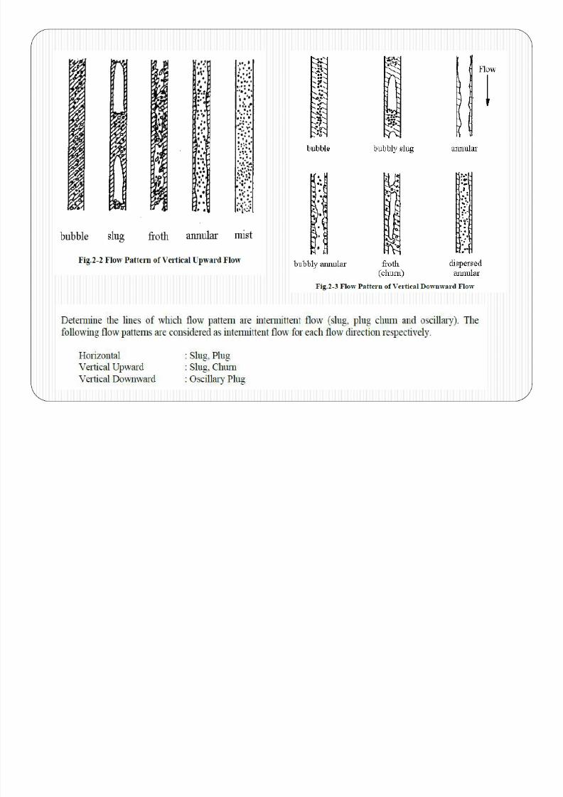
C. Flow Pattern of Two Phase Flow

7/17/2019 Pipe Stress Analysis With Caesar II
http://slidepdf.com/reader/full/pipe-stress-analysis-with-caesar-ii 54/60
Figure 2-1,2-2 and 2-3 show the pattern of horizontal flow, vertical upward flow, and
vertical downward flow.
7/17/2019 Pipe Stress Analysis With Caesar II
http://slidepdf.com/reader/full/pipe-stress-analysis-with-caesar-ii 55/60
D. Classification of Excitation Force by Intermitten Flow

7/17/2019 Pipe Stress Analysis With Caesar II
http://slidepdf.com/reader/full/pipe-stress-analysis-with-caesar-ii 56/60
y
The Excitation Force by Intermitten Flow can be classified as follows :
L/D < 10 : Flow can’t grow to intermittent flow without enough piping length L/D ≥ 10 : the piping is periodically excited by intermitten flow

7/17/2019 Pipe Stress Analysis With Caesar II
http://slidepdf.com/reader/full/pipe-stress-analysis-with-caesar-ii 57/60
Exciting force by intermittent flow
Exciting force by intermittent flow shall be considered against piping support
design and Civil information based on the following criteria. Fig.2 shows flow
chart of criteria.
Note;
F : Exciting force by intermittent flow
Fs : Friction force at standard support span at each support point
F = ρ.A.v2
Normally, Flow can’t grow to intermittent flow without enough piping length (L/D = 10)
D : Pipe Diameter
L : Max. pipe length of each horizontal or vertical part with intermittent flow pattern.

7/17/2019 Pipe Stress Analysis With Caesar II
http://slidepdf.com/reader/full/pipe-stress-analysis-with-caesar-ii 58/60
Evaluation of Posibility Vibration
Criteria 1 (Cr1)
If ftp < 0.1 (Hz), Calculation of fp by Modal analysis is not required and further actionsare not necessary.
Criteria 2 (Cr2)
If 0.1 ≤ ftp < 3.6 (Hz), then fp >5.0 (Hz)
Piping support shall be designed to satisfied that fp is higher than 5.0 (Hz).
Criteria 3 (Cr3)
If 3.6 ≤ ftp, then fp > 1.4 x ftp (Hz)
Piping support shall be designed to satisfied that fp is higher than 1.4 x ftp (Hz).
Note;
ftp : Force frequency caused by intermittent flow
fp : Fundamental natural frequency of piping system

7/17/2019 Pipe Stress Analysis With Caesar II
http://slidepdf.com/reader/full/pipe-stress-analysis-with-caesar-ii 59/60
Fig.1 Criteria for Fundamental natural frequency of piping system

7/17/2019 Pipe Stress Analysis With Caesar II
http://slidepdf.com/reader/full/pipe-stress-analysis-with-caesar-ii 60/60
Fig.2 Criteria for Exciting force by intermittent flow