pipeline strainers - remarkable lighting · pdf filepipeline strainers customer service 1 ......
TRANSCRIPT

pipeline strainers
FOR RESIDENTIAL, COMMERCIALAND INDUSTRIAL APPLICATIONS
®

Pipeline Strainers
Customer Service 1-704-841-6000
Bronze NPT “Y” Strainers . . . . . . . . . . . . . . . . . . . . . . . 6
UL Listed Oil Strainers . . . . . . . . . . . . . . . . . . . . . . . . . 6
Bronze NPT “Y” Strainer / Ball Valve Combination . . . . 7
Bronze Sweat End “Y” Strainers . . . . . . . . . . . . . . . . . 8
59 V Series . . . . . . . . . . . . . . . . . . . . . . . . . . . . . . . . . 9
Cast Iron “Y” Strainers . . . . . . . . . . . . . . . . . . . . . . . . 10
Flanged Cast Bronze “Y” Strainers . . . . . . . . . . . . . . . 11
Cast Carbon Steel & 316 Stainless “Y” Strainers . . . . 12
Flanged Cast Iron “Y” Strainers . . . . . . . . . . . . . . . . . 13
UL Listed Strainers . . . . . . . . . . . . . . . . . . . . . . . . . . 14
Cast Ductile Iron “Y” Strainers . . . . . . . . . . . . . . . . . . 15
Cast Steel Flanged “Y” Strainers . . . . . . . . . . . . . . . . 16
Cast Steel Buttweld “Y” Strainers . . . . . . . . . . . . . . . . 17
Cast Iron Basket Strainers . . . . . . . . . . . . . . . . . . 18-19
Cast Carbon Steel & Stainless Steel Basket Strainers . . 20
Forged Steel Strainers . . . . . . . . . . . . . . . . . . . . . . . 21
Angle Block Strainers . . . . . . . . . . . . . . . . . . . . . . . . 22
Temporary Strainers . . . . . . . . . . . . . . . . . . . . . . . . . 23
Magnets & Magnetic Screen Assemblies . . . . . . . 24-25
Conbraco Industries, Inc. warrants, to its initial purchaser only,that its products which are delivered to this initial purchaserwill be of the kind described in the order or price list and willbe free of defects in workmanship or material for a period ofone year from the date of delivery to you, our initial purchaser.Should any failure to conform to this warranty appear withinone year after the date of the initial delivery to our initial pur-chaser, Conbraco will, upon written notification thereof andsubstantiation that the goods have been stored, installed,maintained and operated in accordance with Conbraco’s rec-ommendations and standard industry practice, correct suchdefects by suitable repair or replacement at Conbraco’s ownexpense.THIS WARRANTY IS EXCLUSIVE AND IS IN LIEU OF ANYIMPLIED WARRANTY OF MERCHANTABILITY, FITNESS FORA PARTICULAR PURPOSE OR OTHER WARRANTY OF QUAL-ITY WHETHER EXPRESSED OR IMPLIED, EXCEPT THEWARRANTY OF TITLE AND AGAINST PATENT INFRINGE-MENT. Correction of non-conformities, in the manner and forthe period of time provided above, shall constitute fulfillment ofall liabilities of Conbraco to our initial purchaser, with respectto the goods, whether based on contract, negligence, strict tortor otherwise. It is the intention of Conbraco Industries, Inc.that no warranty of any kind, whether express or implied, shallpass through our initial purchaser to any other person orcorporation.
LIMITATION OF LIABILITY: Conbraco Industries, Inc. SHALLNOT UNDER ANY CIRCUMSTANCES BE LIABLE FOR SPE-CIAL OR CONSEQUENTIAL DAMAGES SUCH AS, BUT NOTLIMITED TO, DAMAGES OR LOSS OF OTHER PROPERTY OREQUIPMENT, LOSS OF PROFITS OR REVENUE, COST OFCAPITAL, COST OF PURCHASED OR REPLACEMENTGOODS, OR CLAIMS OF CUSTOMERS OF OUR INITIALPURCHASER. THE REMEDIES OF OUR INITIAL PURCHAS-ER, AND ALL OTHERS, SET FORTH HEREIN ARE EXCLU-SIVE, AND THE LIABILITY OF CONBRACO WITH RESPECTTO SAME SHALL NOT, EXCEPT AS EXPRESSLY PROVIDEDHEREIN, EXCEED THE PRICE OF THE CONBRACO GOODSUPON WHICH SUCH LIABILITY IS BASED.
WARRANTY & LIMITATIONS OF LIABILITY
TABLE OF CONTENTS
®
Conbraco Industries offersyou the most extensiveline of strainers availabletoday from a single manufacturer
If you need pipeline strainers to protect expensive equipmentsuch as valves, meters, solenoids, regulators and pumps ina wide variety of applications, Conbraco Industries should beyour source. No other company provides you with more topquality strainer choices.
Conbraco produces more than 40 strainer models in sizesfrom 1/8” to 24”, suitable for everything from O.E.M. applica-tions to heavy process industry use. They are available inbronze; cast iron; stainless, carbon, chrome moly, and forgedsteels. Some models are machined from solid stock.
Select from threaded, flanged, butt weld or socket weld endconnections. There are hundreds of screen options, includ-ing magnetic screen assemblies for extra protection.
You can choose strainers for low-pressure applications suchas swimming pools, high-pressure steam applications, tem-porary strainers for system start-ups, and virtually anythingin-between.
This brochure will help you learn more about all the straineroptions available to you from Conbraco. If you need assis-tance, please feel free to contact your local Conbraco distrib-utor, or call our Customer Service Department at (704) 841-6000. We’ll be happy to help you select the right strainer foryour specific application.

Pipeline Strainers
1Customer Service 1-704-841-6000
Model Material Class Connection Style Size Range Page
Product Index
59 Bronze 400 WOG NPT Y 1/8" - 4" 6
59-UL Bronze 400 WOG NPT Y 1/8" - 1/2" 6
59-00X-06 Bronze 400 WOG Sweat End Y 1/8" - 2" 7
59-300 Bronze 400 WOG Sweat End Y 1/2" - 2" 8
59V Bronze 400 WOG NPT T 1/8" - 1/4" 9
TCG* Cast Iron 250 NPT Y 1/4" - 3" 10
539-15 Bronze 150 Flanged Y 1/4" - 8" 11
539-30 Bronze 300 Flanged Y 1/4" - 8" 11
C531-S* Carbon Steel 600 NPT Y 1/4" - 3" 12
C531-SW* Carbon Steel 600 Socket Weld Y 1/4" - 3" 12
C533-S 316 SS 600 NPT Y 1/4" - 2" 12
C533-SW 316 SS 600 Socket Weld Y 1/4" - 2" 12
FC1* Cast Iron 125 Flanged Y 1-1/2" - 18" 13
FC2* Cast Iron 250 Flanged Y 1-1/2" - 18" 13
UL Listed Cast Iron 125 Flanged Y 2-1/2” - 6” 14
C534-S* Ductile Iron 600 NPT Y 1/4" - 3" 15
531-15 Carbon Steel 150 Flanged Y 1/2" - 8" 16
531-30 Carbon Steel 300 Flanged Y 1/2" - 8" 16
531-60 Carbon Steel 600 Flanged Y 1/2" - 8" 16
533-15 316 SS 150 Flanged Y 1/2" - 8" 16
533-30 316 SS 300 Flanged Y 1/2" - 8" 16
533-60 316 SS 600 Flanged Y 1/2" - 8" 16
550-15 Chrome Moly 150 Flanged Y 1/2" - 8" 16
550-30 Chrome Moly 300 Flanged Y 1/2" - 8" 16
550-60 Chrome Moly 600 Flanged Y 1/2" - 8" 16
531-15BW Carbon Steel 150 Buttweld Y 2" - 8" 17
531-30BW Carbon Steel 300 Buttweld Y 2" - 8" 17
531-60BW Carbon Steel 600 Buttweld Y 2" - 8" 17
533-15BW 316 SS 150 Buttweld Y 2" - 8" 17
533-30BW 316 SS 300 Buttweld Y 2" - 8" 17
533-60BW 316 SS 600 Buttweld Y 2" - 8" 17
550-15BW Chrome Moly 150 Buttweld Y 2" - 8" 17
550-30BW Chrome Moly 300 Buttweld Y 2" - 8" 17
550-60BW Chrome Moly 600 Buttweld Y 2" - 8" 17
528-C12 Cast Iron 125 Flanged Basket 2" - 12" 18
528-B12 Cast Iron 125 Flanged Basket 2" - 12" 19
528-B25 Cast Iron 250 Flanged Basket 2" - 12" 19
527-15 316 SS 150 Flanged Basket 2" - 8" 20
527-30 316 SS 300 Flanged Basket 2" - 8" 20
529-15 Carbon Steel 150 Flanged Basket 2" - 8" 20
529-30 Carbon Steel 300 Flanged Basket 2" - 8" 20
560-S Forged Carbon 1500 NPT Y 1/2" - 2" 21
560-SW Forged Carbon 1500 Socket Weld Y 1/2" - 2" 21
560-BW Forged Carbon 1500 Buttweld Y 1/2" - 2" 21
532-S Carbon Steel 1500 NPT Angle Block 1/2", 3/4" & 1" 22
532-SW Carbon Steel 1500 Socket Weld Angle Block 1/2" - 3" 22
Temporary Strn. Carb Steel & 316 SS 150, 300 & 600 Flanged Cone & Basket 1-1/2" - 18" 23
Magnetic Assy. and inserts 24-25
*Apollo International

Pipeline Strainers
2Customer Service 1-704-841-6000
Part Numbering Matrix
Type
603 - “Y” Type, Bolted Cover 604 - Angle Block 605 - Basket, Clamped Cover
Simplex 606 - Basket, Bolted Cover
Simplex 607 - “Y” Type, #1500 Forged CS 608 - Temporary, Cone Style 609 - Temporary, Basket Style 612 - “Y” Type, Imported, Screwed613 - “Y” Type, Imported, Flanged
Connection
0 - FNPT 1 - Socket Weld 2 - Flanged, Class 125/150 3 - Flanged, Class 250/300 4 - Flanged, Class 600 5 - Butt Weld, Class 150, Sch. 406 - Butt Weld, Class 300, Sch. 407 - Butt Weld, Class 600, Sch. 808 - Butt Weld, Class 1500 9 - Socket Weld X FNPT
Material
1 - Cast Iron 2 - Carbon Steel 3 - 316 (CF8M) 4 - Ductile Iron 5 - Bronze 6 - Chrome Moly, WC6 7 - SAE 1020 8 - Carbon Steel, ASTM A 105 9 - Std% Open Area (Temp. Str. Only) 0 - 150% Open Area (Temp. Str. Only) A - 200% Open Area (Temp. Str. Only) B - Cast Iron, Galvanized C - Cast Iron, Epoxy Coated E - Cast Iron, Plugged Blow Off F - 316, Oxygen Cleaned G - 316, Plugged Blow Off J - Carbon Steel, Plugged Blow Off U - Cast Iron, UL Listed
Size
1 - 1/4" 2 - 3/8" 3 - 1/2" 4 - 3/4" 5 - 1" 6 - 1-1/4" 7 - 1-1/2" 8 - 2" 9 - 2-1/2" 0 - 3" A - 4" B - 5”C - 6”E - 8”G - 10”H - 12”J - 14”K - 16”L - 18”M - 20”P - 24”
1 - 304 SST 2 - MONEL 3 - 316 SST4 - BRASS 5 - CARBON STEEL (TEMP. ONLY) 6 - 304 SST/MAGNETS
7 - MONEL/MAGNETS 8 - 316 SST/MAGNETS 9 - BRASS/MAGNETS A - 316 TEMP W/DOUBLE HNDL B - 316 SPEC GAGE/SPEC FLNG
A - 20 MESH B - 30 MESH C - 40 MESH D - 60 MESH E - 80 MESH F - 100 MESH G - 60/80/100
MESH H - 200 MESH I - .020 PERF J - .027 PERF K - .033 PERF L - .045 PERF
M - .062 PERF N - .125 PERFO - .187 PERF P - .250 PERF Q - .375 PERF R - .312 PERF S - .156 PERFT - 16 MESHU - 12 MESHV - .500 PERFW - 150 MESHY - .093 PERF
Screen Type
Screen
Screen Material
Note: Does not apply to 59 or 59V Series. See pages 6-9.
X X X XX6XX - -

Pipeline Strainers
3Customer Service 1-704-841-6000
*Apollo International
Strainer Comparative Reference
Bronze Screwed 59 352 352 F 39-S 7100 F4SC BT 911 777MI
Bronze Sweat 59 S777
Cast Iron 250# TCG* 11 B B 7000 AISC AT 990-1/2 901 77S/77SIScrewed
Bronze 150# Flanged 539-15 851 851 BA-150 39-15 7101 F4FL BF-150 814
Bronze 300# Flanged 539-30 852 852 BA-300 39-30 7102 F4FL BF-300 818
Cast Steel 600# C531-S* 861-581 861-581 SB 31-S 7200 BISC CT 994-D 921Screwed
Cast Steel 600# C531-SW* 862/582 862/582 SB 31-SW 7209 BISW CT 921-SWSocket Weld
Stainless Steel 600# 533-S 861-SS/ 861-SS/ SSB 33-S 7500 E7SC 316 931Screwed 581-SS 581-SS
Stainless Steel 600# 533-SW 862-SS/ 862-SS 33-SW 7509 E7SW 316-SW 931-SW 88SSocket Weld 582-SS 582-SS
Cast Iron 125# FC1* 751/758 751/758 A-125 A-125 7001 AIFL AF 989-1/2 804 77F-DFlanged
Cast Iron 250# FC2* 752 752 A-250 A-250 7002 AIFL AF 991-1/2 806 77F-D-250Flanged
Ductile Iron Screwed C534-S* 251-DI 251-DI 34-S DT
Cast Steel 150# 531-15 761/781 761/781 SA-150 31-15 7201 BIFL CF-150 828Flanged
Cast Steel 300# 531-30 762/782 762/782 SA-300 31-30 7203 BIFL CF-300 822Flanged
Cast Steel 600# 531-60 764 764 SA-600 31-60 7207 BIFL CF-600 824Flanged
Stainless Steel 150# 533-15 761-SS/ 761-SS/ SSA-150 33-15 7501 G7FL 316-150Flanged 781-SS 781-SS
Stainless Steel 300# 533-30 762-SS/ 762-SS/ SSA-300 33-30 7503 316-300Flanged 782-SS 782-SS
Chrome Moly Flanged 550/15/30/60 766 766 50-F 7400 CIFL
Cast Steel Butt Weld 531-BW 761-WE/ 761-WE/ SA-BW 31-BW 7210 BIBW CF-BW781-WE 781-WE
Stainless Steel 533-BW 762-WE/ 762-WE/ 33-BW 7510 316-BWButt Weld 782-SSWE 782-SSWE
Chrome Moly 550-BW 766-WE 766-WE 50-BW 7400Butt Weld
Chrome Moly 550-SW 865 865 50-SW 7400 CISW 863Socket Weld
Basket Strainer 125# 528-12 155/165 155/165 GVF/HLC 28 528-12 C/BFlanged Iron C/B
Basket Strainer 250# 528-25 166 166 D 28 528-25Flanged Iron
Basket Strainer 150# 529-15 185 185 SD-150 29 529-15Flanged Steel
Basket Strainer 300# 529-30 186 186 SD-300 529-30Flanged Steel
Cast Iron 125# 613CFOD Epoxy Coated
Note: Not all manufacturers use the same screen as standard
Product Cii Mueller Nicholson Keckley Paget Leslie Armstrong Spirax/Sarco Crane Yarway Watts
Class 150 Class 300 Class 600 Class 1500
Degrees Carbon Stainless CM Carbon Stainless CM Carbon Stainless CM Carbon Stainless CMF. Steel Steel Steel Steel Steel Steel Steel Steel Steel Steel Steel Steel
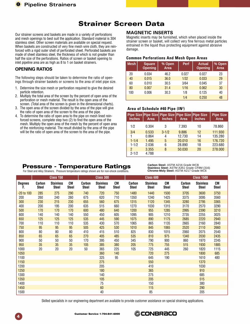
-20 to 100 285 275 290 740 720 750 1480 1440 1500 3705 3600 3750200 260 240 260 675 620 710 1350 1240 1425 3375 3095 3560300 230 215 230 655 560 675 1315 1120 1345 3280 2795 3365400 200 195 200 635 515 660 1270 1030 1315 3170 2570 3290500 170 170 170 600 480 640 1200 955 1285 2995 2390 3210600 140 140 140 550 450 605 1095 905 1210 2735 2255 3025 650 125 125 125 535 445 590 1075 890 1175 2685 2220 2940700 110 110 110 535 430 570 1065 865 1135 2665 2160 2840750 95 95 95 505 425 530 1010 845 1065 2520 2110 2660800 80 80 80 410 415 510 825 830 1015 2060 2075 2540850 65 65 65 270 405 485 535 810 975 1340 2030 2435900 50 50 50 170 395 450 345 790 900 860 1970 2245950 35 35 35 105 385 380 205 775 755 515 1930 1885
1000 20 20 20 50 365 225 105 725 445 260 1820 11151050 360 140 720 275 1800 6851100 325 95 645 190 1610 4801150 275 550 13701200 205 410 10301250 180 365 9101300 140 275 6851350 105 205 5151400 75 150 3801450 60 115 2901500 40 85 205
Skilled specialists in our engineering department are available to provide customer assistance on special straining applications.
Pipeline Strainers
4Customer Service 1-704-841-6000
Our strainer screens and baskets are made in a variety of perforationsand mesh openings to best suit the application. Standard material is 304stainless steel. Other screen materials are available on special request.When baskets are constructed of very fine mesh wire cloth, they are rein-forced with a rigid outer shell of perforated sheet. Perforated baskets aremade of sheet stainless steel, the thickness of which is not greater thanhalf the size of the perforations. Ratios of screen or basket opening toinlet pipeline area are as high as 8 to 1 on basket strainers.
OPENING RATIOS
The following steps should be taken to determine the ratio of open-ings through strainer baskets or screens to the area of inlet pipe size.
1. Determine the size mesh or perforation required to give the desiredparticle retention.
2. Multiply the total area of the screen by the percent of open area of theperforation or mesh material. The result is the open area of thescreen. (Total area of the screen is given in the dimensional charts).
3. The open area of the screen divided by the area of the pipe will givethe ratio of open area of the screen to the area of the pipe.
4. To determine the ratio of open area to the pipe on mesh lined rein-forced screens, complete step two (2) to find the open area of themesh. Multiply the open area of the mesh by the percent of open areaof the reinforcing material. The result divided by the area of the pipewill be the ratio of open area of the screen to the area of the pipe.
Strainer Screen DataMAGNETIC INSERTSMagnetic inserts may be furnished, which when placed inside thestrainer screen or basket, will collect very fine ferrous metal particlesentrained in the liquid thus protecting equipment against abrasivedamage.
20 0.034 46.2 0.027 0.027 2340 0.015 36.0 1/32 0.033 2960 0.010 30.5 3/64 0.045 3780 0.007 31.4 1/16 0.062 30100 0.006 30.3 1/8 0.125 40
1/4 0.250 48
1/2 0.304 3 7.393 10 78.860
3/4 0.533 3-1/2 9.886 12 111.9301 0.864 4 12.730 14 135.2801-1/4 1.495 5 20.010 16 176.7201-1/2 2.036 6 28.890 18 223.6802 3.355 8 50.030 20 278.0002-1/2 4.788
Carbon Steel: ASTM A216 Grade WCBStainless Steel: ASTM A351 Grade CF8M (316)Chrome-Moly Steel: ASTM A217 Grade WC6
Pressure - Temperature Ratings
Common Perforations And Mesh Open AreasMesh Square % Open Perf Actual % Open
Opening Area Opening Area
Area of Schedule #40 Pipe (IN2)Pipe Size Pipe Size Pipe Size Pipe Size Pipe Size Pipe Size Inches Area Inches Area Inches Area
For Steel and Alloy Strainers. Pressure temperature ratings shown are for non-shock conditions.

Pipeline Strainers
5Customer Service 1-704-841-6000
Pressure drop tests for data contained on charts are based on stan-dard screens used for liquid service. Tests conducted at ConbracoIndustries, Inc.’s laboratory indicate a 25% increase in pressure dropwith screens 50% clogged. These figures are based on non-rein-forced screens.
Flow Coefficient: The flow coefficient (Cv) is the number of gallonsper minute of water flowing through a given size restriction at a pres-sure drop of one (1) psig.
To obtain the Cv factor for a given size strainer, read the capacity atthe intersection with one (1) psig pressure drop. Example: Cv for a 5"flanged “Y” type strainer is 470. To determine the pressure drop forliquids other than water, please refer to the multiplying factor data.
Strainer Pressure Drop Data
When specific gravity is other than 1:Multiply the pressure drop from the appropriate chart by the specific gravity of the liquid. (Note: When the specific gravity is less than 1,use 1 as the factor).
SSU Factor SSU Factor SSU Factor SSU Factor
40 .96 100 .70 700 .43 4000 .3150 .85 150 .62 800 .42 5000 .2960 .82 200 .57 900 .41 6000 .28570 .77 300 .52 1000 .39 7000 .2880 .79 400 .48 2000 .35 8000 .27590 .72 500 .46 3000 .33 9000 .27
10000 .26Divide the pressure as determined from the appropriate chart by the factor in the above table to obtain the corrected pressure drop.
% Open Area
Strainer 35 or Over 25 - 35 20 - 25 LinedSize1/4 thru 1 1.0 1.0 1.15 1.251-1/4 thru 2 1.0 1.0 1.4 1.82-1/2 thru 6 1.0 1.2 1.6 2.08 thru 20 1.0 1.3 1.8 2.2
Multiply the pressure drop as determined from appropriate chart by thefactor in the table above to obtain the correct pressure drop.
MULTIPLYING FACTORSScreens Other Than Standard:
Viscosity other than 34 SSU:

Standard Screens:Size Screen Opening1/8” thru 1/2” 50 Mesh3/4” thru 3” 20 Mesh4” .125 Perf.
Model Size A B C (Suffix-02) Wt./100 Screen Area(IN2)
59-000-01 1/8” 2 1-1/4 – 1/8 NPT 44.5 1.3859-001-01 1/4” 2 1-1/4 – 1/8 NPT 42.5 1.3859-002-01 3/8” 2-11/16 2 – 1/4 NPT 78.6 3.1959-003-01 1/2” 2-11/16 2 – 1/4 NPT 75.1 3.1959-004-01 3/4” 3-7/8 3-1/4 – 1/2 NPT 174 8.1859-005-01 1” 4-3/4 4 – 3/4 NPT 276 12.959-006-01 1-1/4” 5-1/8 4-1/4 – 3/4 NPT 358 16.259-007-01 1-1/2” 5-3/4 5 – 1 NPT 541 22.859-008-01 2” 6-3/4 6 – 1-1/4 NPT 747 32.759-009-01 2-1/2” 7-15/16 5-7/8 – 1-1/4 NPT 1130 47.359-010-01 3” 9-1/8 6-7/8 – 1-1/2 NPT 1580 64.859-011-01 4” 11-15/16 10-1/ 8 – 1-1/2 NPT 3070 11559-UL0-01 1/8” 2 1-1/4 – 1/8 NPT 44.5 1.3859-UL1-01 1/4” 2 1-3/4 – 1/8 NPT 42.5 1.3859-UL2-01 3/8” 2-11/16 2 – 1/4 NPT 78.6 3.1959-UL3-01 1/2” 2-11/16 2 – 1/4 NPT 75.1 3.19
Conbraco’s 59 Series “Y” strainers are lightweight and compact. Allsizes offer maximum protection against foreign particles in piping systems and process equipment. Cast bronze body and stainlesssteel screens are completely corrosion resistant. Self-aligning screenis easily accessed for cleaning or service. Operating pressures up to400 psig make the 59 Series an excellent choice as a versatile, multi-purpose strainer. Sizes 1/8” to 1/2” are perfect for OEM applicationsand are available as UL recognized components for use as a sec-ondary strainer on oil burning equipment. Optional tapped caps arealso available for convenient cleaning of the screen and are notplugged (suffix-02). For tapped cap with plug installed use suffix -P2.
• WORKING PRESSURE (non-shock):300 psig @ 350˚F Steam400 psig @ 150˚F Water, Oil, Gas
• SELF ALIGNING SCREENS304 SS (Standard) available in a large variety of meshes (thru 100). Contact factory for optional meshes.
Suffix Key-02 Tapped Cap-P2 Tapped Cap with Plug-06 Strainer/Ball Valve Combination
Pipeline Strainers
6Customer Service 1-704-841-6000
No. Part Material ASTM Spec Remarks
1 Body Bronze B584 UL= B505
2 Cover Bronze B584 UL= B505
3 *Screen Stainless Steel Type 304
4 *Gasket PTFE (3/4” thru 4”)
5 *O-RingSilicone (1/8” thru 1/2”)* Recommended spare parts
Bronze NPT “Y” Strainers
59 Series (85-5-5-5 Bronze)
Dimensional Specifications
Materials of Construction
Note: Dimensions shown are subject to change.

Pipeline Strainers
7Customer Service 1-704-841-6000
Conbraco’s 59-00X-06 Series, with operating pressures up to 400 psig,makes an outstanding choice as a versatile multi-purpose OEM strainer.With the addition of the Apollo® Ball Valve, you receive a high qualityproduct, engineered and designed for safety and outstanding perfor-mance. All sizes offer maximum protection against foreign particles inpiping systems and process equipment. Both the strainer and the ballvalve are completely corrosion resistant. The ball valve, which offers ablow-out-proof stem design, allows for excellent debris removal duringcleaning or blow-off of the screen. Even with the ball valve addition, theself-aligning screen remains easily accessible for routine servicing.
• WORKING PRESSURE (non-shock):300 psig @ 350˚F Steam400 psig @ 150˚F Water, Oil, Gas
• SELF ALIGNING SCREENS304 SS (Standard) available in a large variety of meshes (thru 100). Contact factory for optional meshes.
Dimensional SpecificationsTapped Cap Screen Area
Model Size A B C (Suffix-02) Wt./100 (IN2)
59-003-06 1/2” 2-11/16 3-3/4 6-61/64 – 138 3.1959-004-06 3/4” 3-13/16 2-15/16 8-31/32 – 246 8.1859-005-06 1” 4-3/4 3-5/8 11 – 417 12.959-006-06 1-1/4” 5-1/8 3-15/16 11-1/2 – 499 16.259-007-06 1-1/2” 5-3/4 4-13/32 12-27/64 – 720 22.859-008-06 2” 6-25/32 4-21/32 13-25/32 – 1091 32.7
STANDARD SCREENS:Size Screen Opening1/8” thru 1/2” 50 Mesh3/4” thru 2” 20 Mesh
A
B
C
59-00X-06 Series
Bronze NPT “Y” Strainer & Ball Valve Combination
Note: Dimensions shown are subject to change. Contact factory for exact dimensions when required.
No. Part Material ASTM Spec Remarks1 Body Bronze B5842 Cover Bronze B5843 Ball Valve Bronze B584 70-800 Series4 *Screen Stainless Steel Type 3045 *Gasket PTFE (3/4” thru 2”)6 *O-Ring Silicone (1/8” thru 1/2”)
* Recommended spare parts
Materials of Construction

Conbraco’s 59 Series Sweat End Y-Strainers provide excellent protectionagainst particle contamination in piping systems and process equipment.This lightweight and compact series is designed with minimal wall thicknessat the solder ends to allow for high strength solder joints. These Y-Strainersconsist of bronze bodies and stainless steel screens, and are corrosionresistant. The 59 Series Sweat End Strainers are designed for operatingpressures up to 400 psig and are available in sizes 1/2” through 2”.Optional tapped caps are also available for convenient cleaning of thescreen and are not plugged (suffix-02). For tapped cap with plug installed usesuffix-P2.
Pipeline Strainers
8Customer Service 1-704-841-6000
Tapped Cap Screen AreaModel Size A B (Suffix-02) Wt./100 (IN2)
59-303-01 1/2” 2-3/4 1-13/16 1/4 NPT 50 3.1959-303-P2 1/2" 1/4 NPT 5059-304-01 3/4” 4 2-7/8 1/2 NPT 121 8.1859-304-P2 3/4" 1/2 NPT 12159-305-01 1” 4-3/4 3-9/16 3/4 NPT 189 12.959-305-P2 1" 3/4 NPT 18959-306-01 1-1/4” 5-1/4 3-15/16 3/4 NPT 280 16.259-306-P2 1-1/4" 3/4 NPT 28059-307-01 1-1/2” 6 4-5/8 1 NPT 426 22.859-307-P2 1-1/2" 1 NPT 42659-308-01 2” 7-1/4 5 1-1/4 NPT 627 32.759-308-P2 2" 1-1/4 NPT 627
* STANDARD SCREENS:Size Screen Opening1/2” 50 Mesh3/4” thru 2” 20 Mesh
• WORKING PRESSURE (non-shock):300 psig @ 350˚F Steam400 psig @ 150˚F Water, Oil, Gas
• SELF ALIGNING SCREENS304 SS (Standard) and is available in a variety of meshes (thru100). Contact factory for optional meshes.
• PRESSURE DROPNot available at the time of printing. Please contact CustomerService for proper data.
Bronze Sweat End“Y” Strainers
59-300 Series
Dimensional Specifications
Note: Dimensions shown are subject to change.
Suffix Key-02 Tapped Cap-P2 Tapped Cap with Plug
No. Part Material ASTM Spec Remarks
1 Body Bronze B584
2 Cover Bronze B584
3 *Screen Stainless Steel Type 304
4 *Gasket PTFE 5 *O-Ring PTFE
* Recommended spare parts
Materials of Construction

The body of the 59-V is corrosion-resistant solid cast bronze, ASTM B-584. The removable clean-out cap is solid brass bar stock, ASTM B-16. Standard screens are made of 304 stainless steel, and are 50mesh.
No. Part Material ASTM Spec Remarks
1. Body Cast Bronze B-584
2. Screen Stainless Steel Type 304 50 Mesh
3. O-Ring EPDM
4. Cap Rod Brass B-16Note: Specify suffix -H1 for optional 100 Mesh.
Pipeline Strainers
9Customer Service 1-704-841-6000
Demensional specifications (In.) Weights (Lbs.)
Model Size A B Wt./100
59V-000-01 1/8 NPT 1-3/4 1-1/4 25
59V-001-01 1/4 NPT 2 1-5/16 29.7
1
2
3
4
35
30
25
20
15
10
5
00 1 2 3 4 5 6
1/8”
1/4”
Pres
sure
Dro
p (p
sig)
Flow Rate (GPM)
• WORKING PRESSURE (non-shock):400 psig @ 210˚F WOG125 psig @ 400˚F WSP
• CV FACTORS1/8” 1.03 GPM1/4” 1.42 GPM
59V Series ”Mini” Strainer, sizes 1/8” and 1/4”
”Bronze Mini” Strainers
Dimensional Specifications
Materials of Construction

Pipeline Strainers
10Customer Service 1-704-841-6000
Install these hardworking strainers upstream in almost any application toprotect valves, regulators, solenoids and meters from rust, dirt and pipescale. The “TCG” Series is a rugged 250 lb. WSP-rated strainer con-structed from high-tensile ASTM A-126 Class B cast iron with blow-offconnections and easily removable cylindrical screens. A tapered seat allows screens to be self-aligning and assures a perfectfit. Self-cleaning is easily accomplished by opening the valve or plugconnected to the blow-off outlet. (Not normally furnished plugged.)Blow-off connection is flanged on 2-1/2” and 3” sizes. Corrosion resistant stainless steel screens are standard.
• NPT THREADED ENDS
• WORKING PRESSURE (Non-Shock)250 psig @ 406°F. Steam400 psig @ 150°F. Water, Oil, Gas
• SELF CLEANINGAccomplished by opening the blow-off connection.
• SELF ALIGNING SCREENSAvailable in 304 SS (Standard), 316 SS, Monel and Brass. All materialsare available in a large variety of perforations and meshes.
• PRESSURE DROPSee applicable chart on page 4.
• NPT TAPPED BLOW-OFF CONNECTION
No. Part Material ASTM Spec Remarks1 Body Cast Iron A126 Cl. B2 Plug Cast Iron A126 Cl. B3 *Screen Stainless Steel Type 3044 *Gasket Blue Guard 30005 ***Bolts Carbon Steel Grade 2
* Recommended Spare Parts** Screen shown is standard screen material. Contact customer service for
optional materials and perforations/mesh.*** 2-1/2” & 3” only
TCG Series Sizes 1/4” Thru 3”
Size A B Blow-Off NPT Weight/Lbs. Screen Area In2
1/4” 3-3/16 2-3/8 1/4 1-1/4 2.63/8” 3-3/16 2-3/8 1/4 1-1/4 2.61/2” 3-3/16 2-3/8 1/4 1-1/2 2.63/4” 3-3/4 2-3/8 3/8 2-1/4 7.01” 4 3-1/2 3/8 3 7.31-1/4” 5 4-1/8 3/4 5-1/4 11.71-1/2” 5-3/4 4-11/16 3/4 6-1/2 15.72” 7 5-7/16 1 11-1/8 22.92-1/2” 7-1/2 5-7/16 1-1/4 23-1/2 55.6
3” 7-1/2 5-7/16 1-1/4 33 78.1
Size Screen Opening Suffix1/4” thru 2” 20 Mesh A12 1/2” thru 3” .045 Perf. L1
(Apollo International)
Cast Iron “Y” Strainers
**Standard Screens:
a Note: Demensional specifications shown are subject to change.
Materials of Construction
Dimensional Specifications
TCG Strainer Flow Data
Pipeline Strainers
11Customer Service 1-704-841-6000
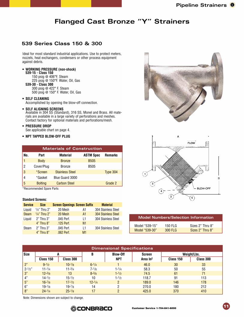
Flanged Cast Bronze “Y” Strainers
539 Series Class 150 & 300
Ideal for most standard industrial applications. Use to protect meters,nozzels, heat exchangers, condensers or other process equipmentagainst debris.
• WORKING PRESSURE (non-shock)539-15 - Class 150
150 psig @ 406°F. Steam225 psig @ 150°F. Water, Oil, Gas
539-30 - Class 300300 psig @ 422° F. Steam500 psig @ 150° F. Water, Oil, Gas
• SELF CLEANINGAccomplished by opening the blow-off connection.
• SELF ALIGNING SCREENSAvailable in 304 SS (Standard), 316 SS, Monel and Brass. All mate-rials are available in a large variety of perforations and meshes.Contact factory for optional materials and perforations/mesh.
• PRESSURE DROPSee applicable chart on page 4.
• NPT TAPPED BLOW-OFF PLUG
Materials of ConstructionNo. Part Material ASTM Spec Remarks
1 Body Bronze B505
2 Cover/Plug Bronze B505
3 *Screen Stainless Steel Type 304
4 *Gasket Blue Guard 3000
5 Bolting Carbon Steel Grade 2*Recommended Spare Parts
Standard Screens:Service Size Screen Openings Screen Suffix MaterialLiquid 1/4” Thru 2” 20 Mesh A1 304 Stainless SteelSteam 1/4” Thru 2” 20 Mesh A1 304 Stainless SteelLiquid 2” Thru 3” .045 Perf. L1 304 Stainless Steel
4” Thru 8” .125 Perf. N1Steam 2” Thru 3” .045 Perf. L1 304 Stainless Steel
4” Thru 8” .062 Perf. M1
Model “539-15” 150 FLG Sizes 2” Thru 8”Model “539-30” 300 FLG Sizes 2” Thru 8”
Model Numbers/Selection Information
z
Size A B Blow-Off Screen Weight/Lbs.Class 150 Class 300 NPT Area In2 Class 150 Class 300
2” 9-1/2 10-1/8 6-1/4 1 46.0 30 332-1/2” 11-1/4 11-3/4 7-1/8 1-1/4 58.3 50 553” 12-3/8 13 8-3/8 1-1/2 74.5 61 714” 14-1/2 15-1/2 10 1-1/2 118.7 91 1135” 16-7/8 17-1/2 12-1/4 2 189.0 146 1786” 19-1/8 19-7/8 14 2 270.0 180 2128” 24-1/4 25-1/8 17 2 425.0 370 410
Materials of Construction
Dimensional Specifications
Standard Screens:
Note: Dimensions shown are subject to change.

Pipeline Strainers
12Customer Service 1-704-841-6000
Materia
Carbon Steel
No. Part Material ASTM Spec Remarks1 Body Carbon Steel A216 Grade WCB2 Plug (1/4” - 1 1/4”) Carbon Steel Multi-Cut Biz®
2 Plug (1-1/2” - 2”) Carbon Steel A216 Grade WCB2 Cover (2-1/2” - 3”) Carbon Steel A515 Grade 603 *Screen Stainless Steel Type 3044 *Gasket (1/4” - 1-1/2”) Copper4 *Gasket (2”) 304 SS/Carbon Graphite Spiral Wound4 *Gasket (2-1/2” - 3”) Carbon Graphite5 Bolting Carbon Steel Grade 5Stainless Steel
STAINLESS STEELNo. Part Material ASTM Spec Remarks1 Body Stainless Steel A351 Grade CF8M (316)
2 Plug (1/4” - 1-1/4”) Stainless Steel A276 Grade 3162 Cover (1-1/2” - 2”) Stainless Steel A351 Grade CF8M (316)
3 *Screen Stainless Steel Type 3044 *Gasket (1/4” - 2”) 304 SS/Carbon Graphite Spiral Wound4 *Gasket (2-1/2” - 3”) Carbon Graphite5 Bolting Stainless Steel Type 316
* Recommended Spare Parts
• STANDARD SCREENS:1/4” Thru 2” - 20 Mesh/304 Stainless Steel2-1/2” & 3” - .045 Perf./304 Stainless Steel
• PRESSURE DROP:See applicable chart on page 5.
Cast Carbon Steel & 316 Stainless “Y” Strainers
Size A B Blow-Off NPT Weight/Lbs. Screen Area In2
1/4” 2-11/16 2-1/16 1/4 1 2.53/8” 2-11/16 2-1/16 1/4 1 2.51/2” 3-3/8 2-3/4 3/8 2 5.43/4” 4-7/16 3-5/8 3/8 3-3/4 8.71” 4-7/8 3-3/4 1/2 4 12.71-1/4” 5-3/8 4-3/8 3/4 7 18.11-1/2” 6-3/8 5-1/8 3/4 8-3/4 25.32” 7-1/2 6 1 12 39.22-1/2”* 10-9/16 7 1-1/4 37 58.33"* 10-15/16 8-1/8 1-1/4 48 76.7
* Note: Available in carbon steel only
Carbon Steel Sizes 1/4” Thru 3”
Model “C531-S” NPTModel “C531-SW Socket Weld (1/2”-2”)Stainless Steel Sizes 1/4” Thru 2”
Model“533-S” NPTModel “533-S W Socket Weld (1/2”-2”)
Threaded & Socket Weld C531-S & SW Series C533-S & SW Series
Durable carbon or stainless steel, threaded or socket, in sizes 1/4”through 3”.
• WORKING PRESSURE (Non-Shock)Carbon Steel
600 psig @ 839°F. Steam1480 psig @ 100°F. Water, Oil & Gas
Stainless Steel600 psig @ 1124°F. Steam1440 psig @ 100°F. Water, Oil & Gas
Model Numbers/Selection Information
(Apollo International)
Materials of Construction
Dimensional Specifications

Pipeline Strainers
13Customer Service 1-704-841-6000
A B Size Weight Lbs. Screen Size Class 125 Class 250 Class 125 Class 250 Blow-Off Class 125 Class 250 Area
Flanged Flanged Flanged Flanged Plug Flanged Flanged In2
1-1/2” 9-1/2 9-1/2 5-7/16 5-7/16 3/4 16 22 23.22” 9-1/2 11-5/8 6-1/2 6-1/8 1 24 28 34.5
2-1/2” 10-1/2 13 7 6-3/4 1-1/4 33 38 47.33” 12 14 8 8 1-1/4 44 54 64.84” 14-7/8 17-1/16 10-3/4 10-3/4 1-1/4 85 110 127.25” 17-3/8 19-1/16 13-1/2 13-1/2 1-1/2 117 160 198.76” 21 21-1/16 16-1/4 16-1/4 1-1/2 174 224 286.08” 22-1/2 23 17 19-1/2 2 262 468 327.510” 26-1/8 28 20-1/4 21-1/4 2-1/2 410 590 550.012” 30-3/8 32-5/8 24 25 2-1/2 604 890 759.014” 36 37-5/8 29 29-1/2 2 815 1080 1052.016” 37 38-15/16 33 33-1/2 2-1/2 1224 1800 1406.018” 46 47-5/8 35-1/2 36-1/2 3 1990 2380 1772.0
13
Flanged Cast Iron “Y” StrainersClass 125 & 250 “FC1” & "FC2" Series
(Also available with FDA approved epoxy coating, see page24. 2-1/2” - 6” available as UL listed – see page 24)
Same great features as “TCG” Series but with flanged connections for applications from 1-1/2”through 18”. Protects process equipment against harmful debris.• WORKING PRESSURE (Non-Shock)
Model FC1 - Class 125 Sizes 1-1/2” Thru 12”
125 psig @ 450°F. Steam • 200 psig @ 150°F. Water, Oil, GasSizes 14” Thru 18”
125 psig @ 250°F. Steam • 150 psig @ 150°F. Water, Oil, GasModel FC2 - Class 250
Sizes 1-1/2” Thru 12”250 psig @ 450°F. Steam • 500 psig @ 150°F. Water, Oil, Gas
Sizes 14” Thru 18”250 psig @ 275°F. Steam • 300 psig @ 150°F. Water, Oil,Gas
• SELF CLEANINGAccomplished by opening the blow-off connection.
• SELF ALIGNING SCREENSAvailable in 304SS (Standard), 316 SS, Monel and Brass. All materials are available inlarge variety of perforations and meshes. Contact factory for optional materials andperforations/mesh.
• PRESSURE DROPSee applicable chart on page 5.
• NPT TAPPED BLOW-OFF CONNECTION
Materials of ConstructionNo. Part Material ASTM Spec Remarks1 Body Cast Iron A126 Cl.B2 Cover Cast Iron A126 Cl.B3 * Screen Stainless Steel Type 3044 *Gasket Blue Guard 30005 Bolting Carbon Steel Grade 2
* Recommended Spare Parts
Screen ScreenService Size Openings Suffix Material
1-1/2” Thru 3” .045 Perf. L1Liquid 4” Thru 16” .125 Perf. N1 304 Stainless Steel
18” .250 Perf. P11-1/2” Thru 6” .045 Perf. L1
Steam 8” Thru 16” .062 Perf. M1 304 Stainless Steel18” .125 Perf. N1
(Apollo International)
Materials of Construction
Dimensional Specifications
Standard Screens:
Pipeline Strainers
14Customer Service 1-704-841-6000
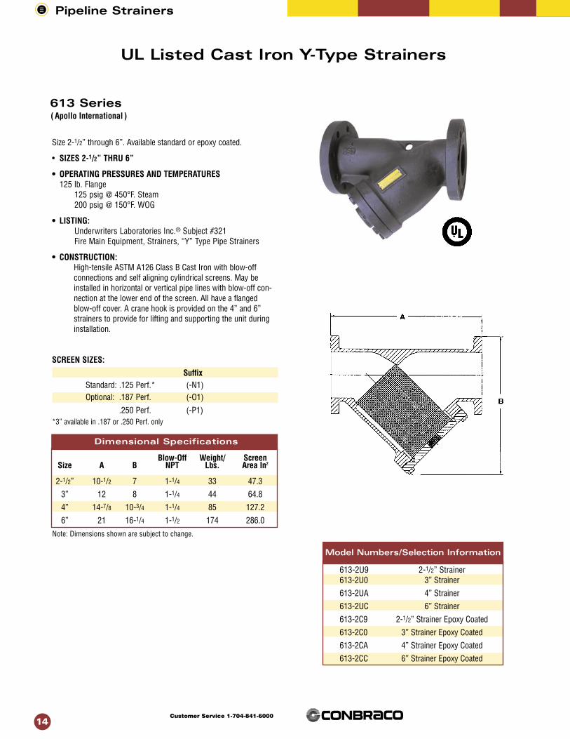
Size 2-1/2” through 6”. Available standard or epoxy coated.
• SIZES 2-1/2” THRU 6”
• OPERATING PRESSURES AND TEMPERATURES125 lb. Flange
125 psig @ 450°F. Steam200 psig @ 150°F. WOG
• LISTING:Underwriters Laboratories Inc.® Subject #321Fire Main Equipment, Strainers, “Y” Type Pipe Strainers
• CONSTRUCTION:High-tensile ASTM A126 Class B Cast Iron with blow-offconnections and self aligning cylindrical screens. May beinstalled in horizontal or vertical pipe lines with blow-off con-nection at the lower end of the screen. All have a flangedblow-off cover. A crane hook is provided on the 4” and 6”strainers to provide for lifting and supporting the unit duringinstallation.
SCREEN SIZES:
SuffixStandard: .125 Perf.* (-N1)Optional: .187 Perf. (-O1)
.250 Perf. (-P1)*3” available in .187 or .250 Perf. only
Blow-Off Weight/ ScreenSize A B NPT Lbs. Area In2
2-1/2” 10-1/2 7 1-1/4 33 47.3
3” 12 8 1-1/4 44 64.8
4” 14-7/8 10-3/4 1-1/4 85 127.2
6” 21 16-1/4 1-1/2 174 286.0
613-2U9 2-1/2” Strainer613-2U0 3” Strainer
613-2UA 4” Strainer
613-2UC 6” Strainer
613-2C9 2-1/2” Strainer Epoxy Coated
613-2C0 3” Strainer Epoxy Coated
613-2CA 4” Strainer Epoxy Coated
613-2CC 6” Strainer Epoxy Coated
UL Listed Cast Iron Y-Type Strainers
613 Series
Model Numbers/Selection Information
( Apollo International )
Dimensional Specifications
Note: Dimensions shown are subject to change.
Pipeline Strainers
15Customer Service 1-704-841-6000
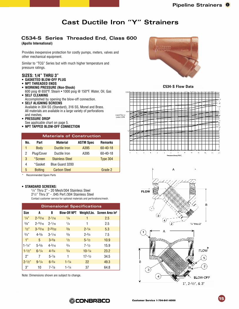
Provides inexpensive protection for costly pumps, meters, valves andother mechanical equipment.
Similar to “TCG” Series but with much higher temperature andpressure ratings.
SIZES: 1/4” THRU 3”• GASKETED BLOW-OFF PLUG• NPT THREADED ENDS• WORKING PRESSURE (Non-Shock)
600 psig @ 650°F. Steam • 1000 psig @ 150°F. Water, Oil, Gas• SELF CLEANING
Accomplished by opening the blow-off connection.• SELF ALIGNING SCREENS
Available in 304 SS (Standard), 316 SS, Monel and Brass. All materials are available in a large variety of perforations and meshes.
• PRESSURE DROPSee applicable chart on page 5.
• NPT TAPPED BLOW-OFF CONNECTION
Materials of ConstructionNo. Part Material ASTM Spec Remarks
1 Body Ductile Iron A395 60-40-18
2 Plug/Cover Ductile Iron A395 60-40-18
3 *Screen Stainless Steel Type 304
4 *Gasket Blue Guard 3200
5 Bolting Carbon Steel Grade 2* Recommended Spare Parts
• STANDARD SCREENS:1/4” Thru 2” - 20 Mesh/304 Stainless Steel21/2” Thru 3” - .045 Perf./304 Stainless SteelContact customer service for optional materials and perforations/mesh.
Dimensional Specifications
Size A B Blow-Off NPT Weight/Lbs. Screen Area In2
1/4” 2-13/16 2-1/16 1/4 1 2.53/8” 2-13/16 2-1/16 1/4 1 2.51/2” 3-13/16 2-25/32 3/8 2-1/4 5.33/4” 4-3/8 3-1/16 3/8 2-3/4 7.5
1” 5 3-5/8 1/2 5-1/2 10.9
1-1/4” 5-5/8 4-3/16 3/4 7-1/2 15.9
1-1/2” 6-1/4 4-3/4 3/4 10-1/4 23.2
2” 7 5-7/8 1 17-1/2 34.5
2-1/2” 9-1/4 6-3/4 1-1/4 22 49.3
3” 10 7-7/8 1-1/4 37 64.8
Note: Dimensions shown are subject to change.
15
C534-S Series Threaded End, Class 600
Cast Ductile Iron “Y” Strainers
(Apollo International)
Materials of Construction
Dimensional Specifications
1”, 2-1/2”, & 3”
Liquid Flow w(water) GPM
C534-S Flow Data
Pipeline Strainers
16Customer Service 1-704-841-6000
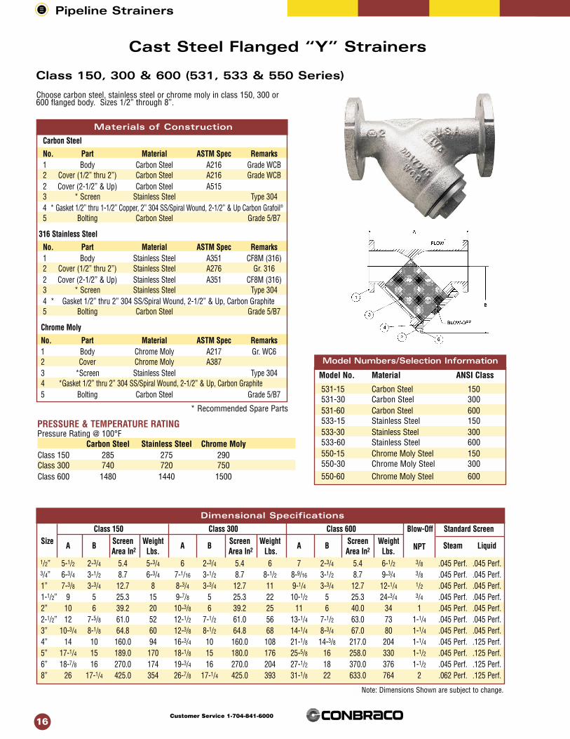
Cast Steel Flanged “Y” Strainers
Choose carbon steel, stainless steel or chrome moly in class 150, 300 or600 flanged body. Sizes 1/2” through 8”.
Carbon Steel
No. Part Material ASTM Spec Remarks1 Body Carbon Steel A216 Grade WCB2 Cover (1/2” thru 2”) Carbon Steel A216 Grade WCB2 Cover (2-1/2” & Up) Carbon Steel A5153 * Screen Stainless Steel Type 3044 * Gasket 1/2” thru 1-1/2” Copper, 2” 304 SS/Spiral Wound, 2-1/2” & Up Carbon Grafoil®
5 Bolting Carbon Steel Grade 5/B7
316 Stainless Steel
No. Part Material ASTM Spec Remarks1 Body Stainless Steel A351 CF8M (316)2 Cover (1/2” thru 2”) Stainless Steel A276 Gr. 3162 Cover (2-1/2” & Up) Stainless Steel A351 CF8M (316)3 * Screen Stainless Steel Type 3044 * Gasket 1/2” thru 2” 304 SS/Spiral Wound, 2-1/2” & Up, Carbon Graphite5 Bolting Carbon Steel Grade 5/B7
Chrome Moly
No. Part Material ASTM Spec Remarks1 Body Chrome Moly A217 Gr. WC62 Cover Chrome Moly A3873 *Screen Stainless Steel Type 3044 *Gasket 1/2” thru 2” 304 SS/Spiral Wound, 2-1/2” & Up, Carbon Graphite5 Bolting Carbon Steel Grade 5/B7
* Recommended Spare Parts
Model No. Material ANSI Class
531-15 Carbon Steel 150531-30 Carbon Steel 300531-60 Carbon Steel 600533-15 Stainless Steel 150533-30 Stainless Steel 300533-60 Stainless Steel 600550-15 Chrome Moly Steel 150550-30 Chrome Moly Steel 300550-60 Chrome Moly Steel 600
Note: Dimensions Shown are subject to change.
Class 150, 300 & 600 (531, 533 & 550 Series)
Model Numbers/Selection Information
Materials of Construction
PRESSURE & TEMPERATURE RATINGPressure Rating @ 100°F
Carbon Steel Stainless Steel Chrome MolyClass 150 285 275 290Class 300 740 720 750Class 600 1480 1440 1500
Dimensional Specifications
Class 150 Class 300 Class 600 Blow-Off Standard ScreennSize A B Screen Weight A B Screen Weight A B Screen Weight
NPT Steam LiquidArea In2 Lbs. Area In2 Lbs. Area In2 Lbs.
1/2” 5-1/2 2-3/4 5.4 5-3/4 6 2-3/4 5.4 6 7 2-3/4 5.4 6-1/2 3/8 .045 Perf. .045 Perf.3/4” 6-3/4 3-1/2 8.7 6-3/4 7-1/16 3-1/2 8.7 8-1/2 8-9/16 3-1/2 8.7 9-3/4 3/8 .045 Perf. .045 Perf.1” 7-3/8 3-3/4 12.7 8 8-3/4 3-3/4 12.7 11 9-1/4 3-3/4 12.7 12-1/4 1/2 .045 Perf. .045 Perf.1-1/2” 9 5 25.3 15 9-7/8 5 25.3 22 10-1/2 5 25.3 24-3/4 3/4 .045 Perf. .045 Perf.2” 10 6 39.2 20 10-3/8 6 39.2 25 11 6 40.0 34 1 .045 Perf. .045 Perf.2-1/2” 12 7-5/8 61.0 52 12-1/2 7-1/2 61.0 56 13-1/4 7-1/2 63.0 73 1-1/4 .045 Perf. .045 Perf.3” 10-3/4 8-1/8 64.8 60 12-3/8 8-1/2 64.8 68 14-1/4 8-3/4 67.0 80 1-1/4 .045 Perf. .045 Perf.4” 14 10 160.0 94 16-3/4 10 160.0 108 21-1/8 14-3/8 217.0 204 1-1/4 .045 Perf. .125 Perf.5” 17-1/4 15 189.0 170 18-1/8 15 180.0 176 25-5/8 16 258.0 330 1-1/2 .045 Perf. .125 Perf.6” 18-7/8 16 270.0 174 19-3/4 16 270.0 204 27-1/2 18 370.0 376 1-1/2 .045 Perf. .125 Perf.8” 26 17-1/4 425.0 354 26-7/8 17-1/4 425.0 393 31-1/8 22 633.0 764 2 .062 Perf. .125 Perf.

Pipeline Strainers
17Customer Service 1-704-841-6000
17
Size 2” through 8” buttweld “Y” strainers in carbon steel, stainlesssteel and chrome moly.
CARBON STEELNo. Part Material ASTM Spec Remarks1 Body Carbon Steel A216 Grade WCB2 Cover (2”) Carbon Steel A216 Grade WCB2 Cover (2-1/2” & Up) Carbon Steel A5153 *Screen Stainless Steel Type 3044 *Gasket 2” 304 SS/Spiral Wound, 2-1/2” & Up, Carbon Graphite5 Bolting Carbon Steel Grade 5/B7
316 STAINLESS STEELNo. Part Material ASTM Spec Remarks1 Body Stainless Steel A351 CF8M (316)2 Cover (2”) Stainless Steel A276 Gr. 3162 Cover (2-1/2” & Up) Stainless Steel A351 CF8M (316)3 *Screen Stainless Steel Type 3044 *Gasket 2” 304 SS/Spiral Wound, 2-1/2” & Up, Carbon Graphite5 Bolting Carbon Steel Grade 5/B7
CHROME MOLYNo. Part Material ASTM Spec Remarks1 Body Chrome Moly A217 Gr. WC62 Cover Chrome Moly A3873 *Screen Stainless Steel Type 3044 *Gasket 2” 304 SS/Spiral Wound, 2-1/2” & Up, Carbon Graphite5 Bolting Carbon Steel Grade 5/B7 Model No. Material ANSI Class
531-15BW Carbon Steel 150/SCH. 40531-30BW Carbon Steel 300/SCH. 40531-60BW Carbon Steel 600/SCH. 80533-15BW Stainless Steel 150/SCH. 40533-30BW Stainless Steel 300/SCH. 40533-60BW Stainless Steel 600/SCH. 80550-15BW Chrome Moly Steel 150/SCH. 40550-30BW Chrome Moly Steel 300/SCH. 40550-60BW Chrome Moly Steel 600/SCH. 80
Model Number/Selection Information
Class 150, 300 & 600 (531, 533 & 550 Series)
Cast Steel Buttweld “Y” Strainers
Pressure & Temperature RatingPressure Rating @ 100°F
Carbon Steel Stainless Steel Chrome MolyClass 150 285 275 290Class 300 740 720 750Class 600 1480 1440 1500
Materials of Construction
Dimensional Specifications
* Recommended Spare Parts
Note: Dimensions Shown are subject to change.
Class 150 Class 300 Class 600Blow-Off
Standard ScreenSize A B Screen Weight A B Screen Weight A B Screen Weight
NPT Steam LiquidArea In2 Lbs. Area In2 Lbs. Area In2 Lbs.
2” 11 6 39.2 17 11 6 39.2 17 11 6 40.0 20 1 .045 Perf. .045 Perf.2-1/2” 12-5/8 7-5/8 61.0 42 12-5/8 7-1/2 61.0 42 12-5/8 7-1/2 63.0 47 1-1/4 .045 Perf. .045 Perf.3” 14-1/4 8-1/8 64.8 46 14-1/4 8-1/2 64.8 46 14-1/4 8-3/4 67.0 52 1-1/4 .045 Perf. .045 Perf.4” 16 10 160.0 64 14 10 160.0 64 21-1/8 14-3/8 217.0 143 1-1/4 .045 Perf. .125 Perf.5” 17-1/4 15 189.0 126 17-1/4 15 189.0 126 25-1/4 16 258.0 223 1-1/2 .045 Perf. .125 Perf.6” 19-3/4 16 270.0 190 19-3/4 16 270.0 190 27-1/2 18 370.0 250 1-1/2 .045 Perf. .125 Perf.8” 26 17-1/4 425.0 293 26 17-1/4 425.0 293 30-3/8 22 633.0 593 2 .062 Perf. .125 Perf.

Pipeline Strainers
18Customer Service 1-704-841-6000
Materials of Construction:
No. Part Material ASTM Spec Remarks
1 Body Cast Iron A126 Cl. B
2 Cover Cast Iron A126 Cl. B
3 *Basket Assy. Stainless Steel Type 304
4 *Gasket Blue Guard 3000 (Sizes 2” thru 5”)
4 *O-Ring Nitrile (Sizes 6” thru 16”)
5 Clamp Ductile Iron A395
6 Clamp Screw Carbon Steel
7 Pipe Plug (2” thru 6”) Carbon Steel Not Shown
E Size A B C Drain Clearance Maximum Basket Weight
NPT For Basket Working Area Lbs.Removal Pressure In2 Liquid Steam
2” 8-1/8 9-3/4 5 3/4 3-7/8 75 34 22 .045 Perf. .045 Perf.
2-1/2” 8-3/4 11-3/8 5-5/16 3/4 4-5/8 75 48 31 .045 Perf. .045 Perf.
3” 9-3/4 13-1/8 6-1/2 3/4 6 60 68 42 .045 Perf. .045 Perf.
4” 11-1/2 15-1/2 8 1 7-3/8 50 105 70 .125 Perf. .045 Perf.
5” 13-1/8 16-3/8 8 1 8 35 127 90 .125 Perf. .045 Perf.
6” 14-7/8 17-7/8 8-5/8 1-1/4 8-5/8 50 155 124 .125 Perf. .045 Perf.
8” 18-11/16 26-3/4 11-3/4 3/4 11-5/8 50 244 270 .125 Perf. .062 Perf.
10” 20-1/8 32-3/4 13-3/4 3/4 13-1/2 50 378 384 .125 Perf. .062 Perf.
12” 26-1/4 38 16-3/8 1 17-3/4 50 553 670 .125 Perf. .062 Perf.
Features clamped cover for easy access to basket for cleaning orreplacement. Ideal for low-pressure applications. Sizes 2” through12”.
MODEL 528-C12• MAXIMUM OPERATING TEMPERATURES
2” thru 5” 450°F. (Gasketed)6” thru 12” 250°F. (O-Ring)
Note: For 6” thru 12”, maximum operating temperature is limitedby the O-Ring material.
• DESIGN:Constructed of high-tensile ASTM A126 Cl. B cast iron. The angledesign provides straight through flow, thus reducing pressure drop.The clamped cover is popular in swimming pool applications andother low pressure systems. Sizes 2” thru 5” have a flat gasket. Sizes6” and larger have an O-Ring.
• SHIPPING NOTE:Shipped with flange protectors to safeguard the flange finish and tokeep foreign material from entering the strainer during shipment andprior to installation. Sizes 2” thru 6” have a pipe plug installed in thedrain connection. Sizes 8” and larger are furnished with a thread pro-tector.
Standard Screen
Cast Iron Basket Strainers
Class 125 Flanged, Clamped Cover 528 Series
Materials of Construction
Dimensional Specifications
* Recommended Spare Parts
Note: Sizes 2” through 6” have bottom drain connection. Sizes 8” and larger have side drain connections. Dimensions shown are subject to change.

Dimensional Da
Class 125 Class 250 Standard BasketE E
Size A B C D Clearance Basket Weight A B C D Clearance Basket WeightDrain For Basket Area In2 Lbs. Drain For Basket Area In2 Lbs. Liquid Steam
Removal Removal
2” 8-1/8 8-3/8 5 3/4 5-3/8 34 22 12-1/8 11-1/2 6-5/8 1-1/4 7-3/4 65.7 64 .045 Perf. .045 Perf.
2-1/2” 8-3/4 9-5/8 5-5/16 3/4 6-5/8 48 31 12-1/2 11-1/2 6-3/8 1-1/4 8 65.7 80 .045 Perf. .045 Perf.
3” 9-3/4 11-5/8 6-1/2 3/4 8 68 42 13-1/2 14-1/4 7-1/4 1-1/2 9-11/16 84.5 116 .045 Perf. .045 Perf.
4” 11-1/2 13-1/2 8 1 9-5/16 105 70 16 14-1/4 7-1/2 1-1/2 9-7/16 95 160 .125 Perf. .045 Perf.
5” 13-1/8 14-5/8 8 1 10-1/4 127 90 14-3/8 15 8-1/4 1 10-1/4 127 176 .125 Perf. .045 Perf.
6” 14-7/8 15-5/8 8-5/8 1-1/4 11-1/8 155 124 18-1/4 16 8-1/4 2 10-13/16 140 234 .125 Perf. .045 Perf.
8” 18-11/16 21 11-3/4 3/4 15-9/16 244 270 19-5/8 20-5/8 11-3/4 3/4 15-9/16 244 340 .125 Perf. .062 Perf.
10” 20-1/8 24-1/2 13-3/4 3/4 18 378 384 22 25 13-3/4 3/4 18 378 550 .125 Perf. .062 Perf.
12” 26-1/4 29-3/4 16-3/8 1 23-1/4 553 670 27-3/4 30-3/4 16-1/2 1 23-1/4 658 970 .125 Perf. .062 Perf.
Pipeline Strainers
19Customer Service 1-704-841-6000
General purpose basket strainer for protection of pumps, meters andother process equipment. Sizes 2” through 12”.
• MAXIMUM OPERATING TEMPERATURESClass 125 (Non-Shock)Steam 125 psig @ 450°F.
WOG 200 psig @ 150°F.
Class 250 (Non-Shock)Steam 250 psig @ 450°F
WOG 500 psig @ 150°F
• DESIGN:Constructed of high-tensile ASTM A126 Cl. B cast iron. The angledesign provides straight through flow, thus reducing pressure drop.These strainers are commonly installed before pumps, meters, andother mechanical equipment.
• SHIPPING NOTE:Shipped with flange protectors to safeguard the flange finish and to keepforeign material from entering the strainer during shipment and prior toinstallation. Sizes 2” thru 6” have a pipe plug installed in the drain con-nection. Sizes 8” and larger are furnished with a thread protector.
• Materials of Construction:No. Part Material ASTM Spec Remarks
1 Body Cast Iron A126 Cl. B
2 Cover Cast Iron A126 Cl. B3 *Basket Assy. Stainless Steel Type 304
4 *Gasket Blue Guard 3000
5 Bolting Carbon SteelModel 528-B12 Class 125 FlangedModel 528-B25 Class 250 Flanged
Class 125 & 250 Flanged
Bolted Cover 528 Series
Cast Iron Basket Strainers
Model Numbers/Selection Information
19
Materials of Construction
Dimensional Specificatioins
* Recommended Spare Parts* Recommended Spare Parts
* Recommended Spare Parts
Note: Sizes 2” thru 6” have bottom drain connection. Sizes 8” & larger have side drain connections.Dimensions shown are subject to change.

Maximum protection for petroleum, power and chemical processingapplications. Sizes 2” through 8”.
• MAXIMUM OPERATING TEMPERATURESCarbon Steel (Non-Shock)
Class 150Steam 150 psig @ 567°F.WOG 285 psig @ 100°F.
Class 300Steam 300 psig @ 839°F.WOG 740 psig @ 100°F.
Stainless Steel (Non-Shock)Class 150
Steam 150 psig @ 567°F.WOG 275 psig @ 100°F.
Class 300Steam 300 psig @ 1125°F.WOG 720 psig @ 100°F.
• DESIGN:The angle design provides straight through flow, thus reducingpressure drop. These strainers are widely used in petroleum, powerand chemical industries.
• SHIPPING NOTE:Shipped with flange protectors to safeguard the flange finish and tokeep foreign material from entering the strainer during shipment and prior to installation. Sizes 2” thru 6” have a pipe plug installedin the drain connection. Size 8” is furnished with a thread protector.
Materials of Construction:No. Part Material ASTM Spec RemarksCarbon Steel1 Body Carbon Steel A216 Gr. WCB2 Cover Carbon Steel A216 Gr. WCB3 *Basket Assy. Stainless Steel Type 3044 *Gasket Carbon Graphite5 Bolting Carbon Steel Grade 5Stainless Steel1 Body 316 Stainless Steel A351 Gr. CF8M2 Cover 316 Stainless Steel A351 Gr. CF8M3 Basket Assy. Stainless Steel Type 3044 *Gasket Carbon Graphite5 Bolting Stainless Steel Grade 8
Pipeline Strainers
20Customer Service 1-704-841-6000
Class 150 Class 300 Class 150 & 300 Standard ScreenSize A B C D Weight. A B C D Weight E Basket Liquid Steam
Lbs Lbs. Clearance Area In2
2” 9 8 4 3/4 29 9-1/2 8 4 3/4 34 5 28 .045 Perf. .045 Perf.
2-1/2” 11-7/8 11-1/2 6-3/8 1-1/4 75 12-1/4 11-1/2 6-3/8 1-1/4 80 8-1/2 60 .045 Perf. .045 Perf.
3” 10 11-1/2 6-3/8 3/4 57 10-3/4 11-1/2 6-3/8 3/4 71 7-7/8 62 .045 Perf. .045 Perf.
4” 11 13-3/8 7-3/8 1 91 11-7/8 13-3/8 7-3/8 1 118 9-1/4 102 .125 Perf. .045 Perf.
6” 15-1/8 15-7/8 8-1/2 1 146 16 15-7/8 8-1/2 1 218 13-1/4 158 .125 Perf. .045 Perf.
8” 19 21 11-3/4 2 267 20 21 11-3/4 2 388 14-7/8 251 .125 Perf. .062 Perf.
Model 527-15 316 Stainless Class 150 FlangedModel 527-30 316 Stainless Class 300 FlangedModel 529-15 Carbon Steel Class 150 FlangedModel 529-30 Carbon Steel Class 300 Flanged
Cast Carbon Steel & Stainless Steel Basket Strainers
Class 150 & 300 Flanged, Bolted Cover 527/529 SERIES
Model Numbers/Selection Informaton
* Recommended Spare Parts
Materials of Construction
Note Dimensions shown are subject to change.
Dimensional Specifications

Pipeline Strainers
21Customer Service 1-704-841-6000
Model 560-S Screwed End
Model 560-SW Socket Weld
Model 560-BW Butt Weld
High pressure ratings; for severe process industry and power plantapplications. Choose threaded, socket weld or butt weld in sizes 1/2”through 2”.
• WORKING PRESSURE (Non-Shock)1340 psig @ 850°F. Steam3705 psig @ -20 to 100°F. WOG
• CONFORMS TO THE FOLLOWING STANDARDS:ANSI B2.1 Screwed EndsANSI B16.11 Socket Weld EndsANSI B16.25 Butt Weld Ends
Materials of CoNo. Description Material ASTM Spec. Remarks1 Body Forged Steel A1052 Plug Carbon Steel A108 Gr. 10183 * Screen Stainless Steel 304/40 Mesh4 * Gasket Stainless Steel 304 SS/Carbon Graphite
.
Size A B C D Weight/Lbs. Typical Cv Factors
1/2” 3-1/8 1-3/32 4-1/2 1/4 3-3/4 3.53/4” 3-3/4 1-1/4 5-7/16 1/2 6-1/2 5.6
1” 3-3/4 1-1/4 5-7/16 1/2 6-1/2 12.7
1-1/2” 5-5/16 1-7/8 8-1/4 3/4 15-1/2 35.0
2” 6-5/16 2-7/32 9-1/2 1 24 46.0
Class 1500, 560 Series
Forged Steel Strainers
Model Numbers/Selection Information®
Note: Dimensions shown are subject to change
Materials of Construction
Dimensional Specifications
* Recommended Spare Parts

Pipeline Strainers
22Customer Service 1-704-841-6000
22
Machined from solid stock, ideal for high-pressure steam applica-tions.
• SIZES 1/2” THRU 3”Sizes 1-1/4” thru 3” available in socket weld ends only.
• WORKING PRESSURE (Non-Shock)1500 psig @ 839°F. Steam3705 psig @ -20° to 100°F. WOG
• CONFORMS TO THE FOLLOWING STANDARDS:ANSI B2.1 Screwed EndsANSI B16.11 Socket Weld Ends
• CONSTRUCTION:Carbon steel body available in screwed end or socket weldends. Screen seats are machined for perfect fit.
Materials of Construction:
No. Description Material Spec. Remarks
1 Body Carbon Steel SAE 1020
2 Cover Carbon Steel SAE 1020
3 *Screen Stainless Steel 304/.033 Perf.
4 *Gasket Stainless Steel 304 SS/Carbon Graphite
5 Bolting Carbon Steel
Dimensional DSize A B C Blow-Off Weight/Lbs.1/2” 1-1/2 1-1/4 4-5/16 1/2 7-1/23/4” 1-1/2 1-1/4 4-5/16 1/2 7-1/2
1” 1-7/8 1-3/8 5-3/8 1/2 10
1-1/4” 1-7/8 1-5/8 5-15/16 3/4 15
1-1/2” 1-7/8 1-5/8 5-15/16 3/4 15
2” 2-5/8 2 7-3/4 1 30
2-1/2” 3-3/8 2-3/4 10-5/8 1-1/4 65
3” 3-3/8 2-3/4 10-5/8 1-1/4 65
532-S Screwed End532-SW Socket Weld
Angle Block Strainers
Threaded & Socket Weld, 532 Series
Model Numbers/Selection Information®
Materials of Construction
Dimensional Specifications
Note: Dimensions shown are subject to change.
* Recommended Spare Parts
Pipeline Strainers
23Customer Service 1-704-841-6000
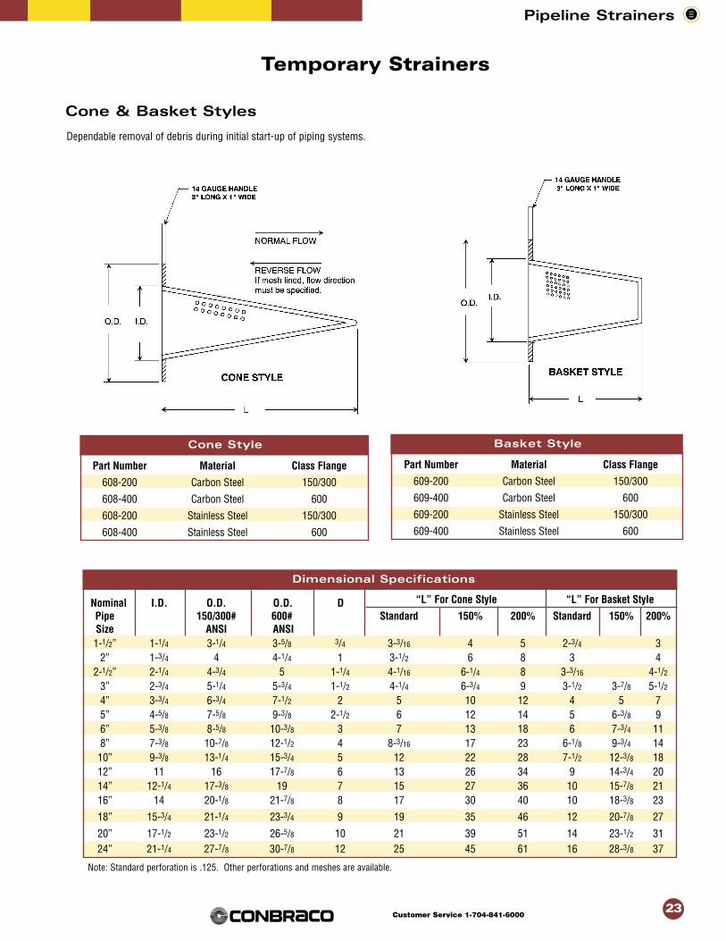
Cone StylePart Number Material Class Flange
608-200 Carbon Steel 150/300
608-400 Carbon Steel 600
608-200 Stainless Steel 150/300
608-400 Stainless Steel 600
Basket StylePart Number Material Class Flange
609-200 Carbon Steel 150/300
609-400 Carbon Steel 600
609-200 Stainless Steel 150/300
609-400 Stainless Steel 600
Dependable removal of debris during initial start-up of piping systems.
23
Cone & Basket Styles
Temporary Strainers
Nominal I.D. O.D. O.D. D “L” For Cone Style “L” For Basket Style
Pipe 150/300# 600# Standard 150% 200% Standard 150% 200%Size ANSI ANSI1-1/2” 1-1/4 3-1/4 3-5/8 3/4 3-3/16 4 5 2-3/4 3
2” 1-3/4 4 4-1/4 1 3-1/2 6 8 3 42-1/2” 2-1/4 4-3/4 5 1-1/4 4-1/16 6-1/4 8 3-3/16 4-1/2
3” 2-3/4 5-1/4 5-3/4 1-1/2 4-1/4 6-3/4 9 3-1/2 3-7/8 5-1/24” 3-3/4 6-3/4 7-1/2 2 5 10 12 4 5 75” 4-5/8 7-5/8 9-3/8 2-1/2 6 12 14 5 6-3/8 96” 5-3/8 8-5/8 10-3/8 3 7 13 18 6 7-3/4 118” 7-3/8 10-7/8 12-1/2 4 8-3/16 17 23 6-1/8 9-3/4 1410” 9-3/8 13-1/4 15-3/4 5 12 22 28 7-1/2 12-3/8 1812” 11 16 17-7/8 6 13 26 34 9 14-3/4 2014” 12-1/4 17-3/8 19 7 15 27 36 10 15-7/8 2116” 14 20-1/8 21-7/8 8 17 30 40 10 18-3/8 23
18” 15-3/4 21-1/4 23-3/4 9 19 35 46 12 20-7/8 27
20” 17-1/2 23-1/2 26-5/8 10 21 39 51 14 23-1/2 3124” 21-1/4 27-7/8 30-7/8 12 25 45 61 16 28-3/8 37
Note: Standard perforation is .125. Other perforations and meshes are available.
Cone Style Basket Style
Dimensional Specifications

Pipeline Strainers
24Customer Service 1-704-841-6000
Example “A” - Rod Magnet
“Y” Type - Sizes 1/2" thru 1-1/4"
“Y” Type - Sizes 1-1/2" & 2"
1/4" Dia. MagnetMagnet
Spacer
Horseshoe Type Magnet
EXAMPLE “B” - HORSESHOE MAGNET
Rod or Horseshoe Type Magnet
Magnetic Screen Assemblies For Extra ProtectionAgainst Fine Ferrous Metal Particles
Now you can get added protection for yourhydraulic system, pumps and other equipment.
Magnetic screen assemblies prevent fineferrous metal particles from passing throughthe screen and damaging bearings and othermachined surfaces.
The magnets in these screen assemblies arepositioned to obtain the strongest magnetic fieldpossible, resulting in the most effective particleretention.
Magnetic screen assemblies are designed to fit all types and sizes of strainers, makingit possible to easily change screens in the field to convert to magnetic strainers.

Pipeline Strainers
25Customer Service 1-704-841-6000
SpecificationsMagnetic inserts are available on “Y” type and“Basket” type strainers in all body materials.
Corrosion resistant fasteners are used to assemblethe magnets to the screen.
Magnets are equally spaced in each row. When twoor more rows are used, the magnets are staggered.
Magnet material is Cast Alnico #5.
Example A - Rod magnet, “Y” type, 1/2" thru 1-1/4"Example B - Horseshoe magnet, “Y” type, 1-1/2" & 2"Example C & D - Channel magnet, “Y” type, 2-1/2"thru 18", and “Basket” type 3" thru 12".
Ordering InformationThese magnetic assemblies are available for allstrainers, regardless of body material or end connec-tions.
Magnetic screen assemblies are used with stainlesssteel screen material only.
The blow-off connection (drain) is not available onstrainers that have rod or horseshoe type magnets.
When ordering, specify, “Magnetic Strainer Screen”.
For other strainer information, see the appropriatestrainer catalog page.
Size 1/2 thru 1-1/4 1-1/2 2 2-1/2 3 4 5 6 8 10 12 14 16 18“Y”Type 1 4 6 3 3 4 10 12 12 12 16 20 24 32Basket Type 2 2 3 3 5 7 11 13 17
EXAMPLE “C” - CHANNEL MAGNET EXAMPLE “D” - CHANNEL MAGNET
Basket Type - Sizes 3" thru 12"2" & 2-1/2" Sizes use Horseshoe Magnets
“Y”Type - Sizes 2-1/2" thru 18"
Magnet Magnet
Channel Type Magnet
Channel Type Magnet
Magnet Quantity

Conway, SC • Matthews, NC • Pageland, SC • Customer Service 1-704-841-6000 • www.conbraco.com
Printed in USA COPYRIGHT 02/02 CICAST00
Sales Department International Sales Department Customer Service DepartmentP.O. Box 247 P.O. Box 247 P.O. Box 247Matthews, NC 28106 Matthews, NC 28106 Matthews, NC 28106Phone: 704-841-6000 Phone: 704-841-6000 Phone: 704-841-6000Fax: 704-841-6020 Fax: 704-841-6020 Fax: 704-841-6020
Sout
heas
tRe
gion
Mid
wes
tern
Reg
ion
Wes
tern
Reg
ion
North
east
Re
gion
Sout
hern
Regi
onCa
nada
Int’l
./Pu
erto
Ric
o
B. Lynch & Assoc. Florida [email protected] 813-901-0988 813-901-8403
Valves & Fittings, Inc. Georgia/Alabama/Tennessee-East [email protected] 770-483-3057 770-483-3110
Pro Marketing, Inc. North Carolina/South Carolina [email protected] 864-578-4334 864-578-4889
Mid South Marketing Virginia/Maryland/Washington, D.C./WV-East [email protected] 804-749-8712 804-749-8717
HEBCO, Inc. Kansas/Missouri-West [email protected] 913-491-0797 913-491-5126
New Tech Marketing, Inc. IL/WI-East/IN-North/MI-Upper Peninsula/IA-River Counties [email protected] 630-378-4300 630-378-0343
New Tech Marketing, Inc. Eastern Missouri/Southern Illinois [email protected] 618-394-0329 618-394-0427
L.J. Whitfill & Associates, Inc. Kentucky/Indiana-South/Ohio-South [email protected] 502-459-4545 502-459-9944
V.E. Sales Co., Inc. Michigan (Except Upper Peninsula) [email protected] 586-774-7760 586-774-1490
Northstar Valve & Fitting, Inc. Minnesota/North & South Dakota/Wisconsin-West [email protected] 952-937-0108 952-937-0803
Willco, Inc. Nebraska/Iowa (Except River Counties) [email protected] 402-573-7000 402-573-7371
Morrissey Associates, Inc. Ohio-North/Pennsylvania-West/West Virginia-West [email protected] 330-538-0406 330-538-0410
Specified Process Equipment Co. California-North [email protected] 707-747-3466 707-747-4957SoCal Controls, Inc. California-South [email protected] 714-935-9533 714-935-9503
Marshall-Rodeno Associated CO/WY/MT/ID-SE/UT/NV-NE/NM/El Paso-TX [email protected] 303-575-6701 303-575-6706
J.P. Harris & Associates, Inc. Washington/Oregon/Idaho-North West/Alaska [email protected] 360-944-8457 360-944-8459
Layden Valve Sales & Solutions Hawaii [email protected] 808-456-3331 808-455-1064
Southwestern Mechnical Sales Co. Arizona/Nevada-SW [email protected] 480-813-1313 480-813-2286
Conbraco Industries, Canada 160 Pennsylvania Ave., Unit 3, Concord, Ontario L4K 4A9 [email protected] 905-761-6161 905-761-6666
Barclay Sales Ltd. British Columbia [email protected] 604-945-1010 604-945-3030
M.A. Stewart & Sons, Ltd. British Columbia, Alberta,Ontario,Quebec [email protected] 604-594-8431 604-594-4335
Mechanical Systems 2000, Inc. Alberta-South [email protected] 403-291-1244 403-219-0686
Dynamic Agencies, Ltd. Saskatchewan [email protected] 306-343-1901 306-343-1901
Tom Beggs Agencies Ltd. Manitoba/NW Ontario [email protected] 204-953-1900 204-774-6915
Task Controls, Inc. Ontario [email protected] 416-291-3004 416-754-3481
Agences J. Pierre Sylvain, Inc. Quebec [email protected] 450-655-9588 450-641-2737
Kern Industries, Ltd. Alberta-North [email protected] 780-451-2056 780-454-6687
J. Levandier Sales, Inc. Nova Scotia, New Brunswick, Prince Edward Island [email protected] 506-858-1615 506-858-1084
Smith Agencies Newfoundland [email protected] 709-364-8856 709-747-9414
Key to the North Sales Agency, Inc. Ontario-North [email protected] 705-566-0148
Pelco Sales Eastern-Ontario/Ottawa [email protected] 613-839-0114 613-839-0115
Southern Marketing Group MS/TN-West/AR/Bowie Cty.-TX [email protected] 901-547-0042 901-547-0035
AVC Mechanical Oklahoma/Texas-North [email protected] 817-649-2229 817-649-2225
Knox & Associates, Inc. Texas-South/Louisiana [email protected] 713-462-7766 713-690-6228
Rafael Rodriguez Barril, Inc. Puerto Rico [email protected] 787-759-8680 787-759-8986
Conbraco Industries, Int’l. (Europe) Manchester, England [email protected] +44-161-908-2340 +44-161-908-2359
Urell, Inc. Massachusetts/New England States [email protected] 617-923-9500 617-926-9414
Pence & Associates New York-Upstate/New York-West [email protected] 315-423-0066 315-423-0290
Continuous Sales Corporation New York-East/New Jersey-North [email protected] 516-248-5177 516-248-5187
J.A. Layden Co. Pennsylvania-East/Delaware/New Jersey-South [email protected] 610-353-2311 610-359-1299
Keith Engle & Associates OEM accounts [email protected] 610-827-9560 610-827-9561
E/Mail Address Phone Fax