pipeline transportation systems for liq
TRANSCRIPT

A N A M E R I C A N N A T I O N A L S T A N D A R D
Pipeline Transportation Systems for Liquid Hydrocarbons and Other Liquids
ASME B31.4-2006(Revision of ASME B31.4-2002)
ASME Code for Pressure Piping, B31
Copyright ASME International Provided by IHS under license with ASME
Not for ResaleNo reproduction or networking permitted without license from IHS
--`,,```,,,,````-`-`,,`,,`,`,,`---

ASME B31.4-2006(Revision of ASME B31.4-2002)
PipelineTransportationSystems for LiquidHydrocarbons andOther Liquids
ASME CODE FOR PRESSURE PIPING, B31
A N A M E R I C A N N A T I O N A L S T A N D A R D
Three Park Avenue • New York, NY 10016
Copyright ASME International Provided by IHS under license with ASME
Not for ResaleNo reproduction or networking permitted without license from IHS
--`,,```,,,,````-`-`,,`,,`,`,,`---

Date of Issuance: October 20, 2006
Mandatory Date: April 20, 2007
The next Edition of this Code is scheduled for publication in 2009. There will be no addenda issuedto this edition.
ASME issues written replies to inquiries concerning interpretations of technical aspects of the Code.Interpretations are published on the ASME Web site under the Committee Pages at http://www.asme.org/codes/ as they are issued.
The user of the Code will note that metric equivalents of U.S. Customary units appear in many placesin this Code. The values stated in U.S. Customary units are to be regarded as the standard, unlessotherwise agreed between the contracting parties.
ASME is the registered trademark of The American Society of Mechanical Engineers.
This code or standard was developed under procedures accredited as meeting the criteria for American NationalStandards. The Standards Committee that approved the code or standard was balanced to assure that individuals fromcompetent and concerned interests have had an opportunity to participate. The proposed code or standard was madeavailable for public review and comment that provides an opportunity for additional public input from industry, academia,regulatory agencies, and the public-at-large.
ASME does not “approve,” “rate,” or “endorse” any item, construction, proprietary device, or activity.ASME does not take any position with respect to the validity of any patent rights asserted in connection with any
items mentioned in this document, and does not undertake to insure anyone utilizing a standard against liability forinfringement of any applicable Letters Patent, nor assume any such liability. Users of a code or standard are expresslyadvised that determination of the validity of any such patent rights, and the risk of infringement of such rights, isentirely their own responsibility.
Participation by federal agency representative(s) or person(s) affiliated with industry is not to be interpreted asgovernment or industry endorsement of this code or standard.
ASME accepts responsibility for only those interpretations issued in accordance with the established ASME proceduresand policies, which precludes the issuance of interpretations by individuals.
No part of this document may be reproduced in any form,in an electronic retrieval system or otherwise,
without the prior written permission of the publisher.
The American Society of Mechanical EngineersThree Park Avenue, New York, NY 10016-5990
Copyright © 2006 byTHE AMERICAN SOCIETY OF MECHANICAL ENGINEERS
All rights reservedPrinted in U.S.A.
Copyright ASME International Provided by IHS under license with ASME
Not for ResaleNo reproduction or networking permitted without license from IHS
--`,,```,,,,````-`-`,,`,,`,`,,`---

CONTENTS
Foreword . . . . . . . . . . . . . . . . . . . . . . . . . . . . . . . . . . . . . . . . . . . . . . . . . . . . . . . . . . . . . . . . . . . . . . . . . . . . . . ixPersonnel . . . . . . . . . . . . . . . . . . . . . . . . . . . . . . . . . . . . . . . . . . . . . . . . . . . . . . . . . . . . . . . . . . . . . . . . . . . . . . xiIntroduction . . . . . . . . . . . . . . . . . . . . . . . . . . . . . . . . . . . . . . . . . . . . . . . . . . . . . . . . . . . . . . . . . . . . . . . . . . . xivSummary of Changes . . . . . . . . . . . . . . . . . . . . . . . . . . . . . . . . . . . . . . . . . . . . . . . . . . . . . . . . . . . . . . . . . . xvi
Chapter I Scope and Definitions400 General Statements . . . . . . . . . . . . . . . . . . . . . . . . . . . . . . . . . . . . . . . . . . . . . . . . 1400.1 Scope . . . . . . . . . . . . . . . . . . . . . . . . . . . . . . . . . . . . . . . . . . . . . . . . . . . . . . . . . . . . . 1400.2 Definitions . . . . . . . . . . . . . . . . . . . . . . . . . . . . . . . . . . . . . . . . . . . . . . . . . . . . . . . . 4
Figures400.1.1 Diagram Showing Scope of ASME B31.4 Excluding Carbon Dioxide
Pipeline Systems (See Fig. 400.1.2) . . . . . . . . . . . . . . . . . . . . . . . . . . . . . . . 2400.1.2 Diagram Showing Scope of ASME B31.4 for Carbon Dioxide
Pipeline Systems . . . . . . . . . . . . . . . . . . . . . . . . . . . . . . . . . . . . . . . . . . . . . . . . 3
Chapter II DesignPart 1 Conditions and Criteria . . . . . . . . . . . . . . . . . . . . . . . . . . . . . . . . . . . . . . . . . . . 7401 Design Conditions . . . . . . . . . . . . . . . . . . . . . . . . . . . . . . . . . . . . . . . . . . . . . . . . . 7401.1 General . . . . . . . . . . . . . . . . . . . . . . . . . . . . . . . . . . . . . . . . . . . . . . . . . . . . . . . . . . . 7401.2 Pressure . . . . . . . . . . . . . . . . . . . . . . . . . . . . . . . . . . . . . . . . . . . . . . . . . . . . . . . . . . . 7401.3 Temperature . . . . . . . . . . . . . . . . . . . . . . . . . . . . . . . . . . . . . . . . . . . . . . . . . . . . . . . 7401.4 Ambient Influences . . . . . . . . . . . . . . . . . . . . . . . . . . . . . . . . . . . . . . . . . . . . . . . . 7401.5 Dynamic Effects . . . . . . . . . . . . . . . . . . . . . . . . . . . . . . . . . . . . . . . . . . . . . . . . . . . 7401.6 Weight Effects . . . . . . . . . . . . . . . . . . . . . . . . . . . . . . . . . . . . . . . . . . . . . . . . . . . . . 7401.7 Thermal Expansion and Contraction Loads . . . . . . . . . . . . . . . . . . . . . . . . . 7401.8 Relative Movement of Connected Components . . . . . . . . . . . . . . . . . . . . . 8402 Design Criteria . . . . . . . . . . . . . . . . . . . . . . . . . . . . . . . . . . . . . . . . . . . . . . . . . . . . 8402.1 General . . . . . . . . . . . . . . . . . . . . . . . . . . . . . . . . . . . . . . . . . . . . . . . . . . . . . . . . . . . 8402.2 Pressure–Temperature Ratings for Piping Components . . . . . . . . . . . . . . 8402.3 Allowable Stresses and Other Stress Limits . . . . . . . . . . . . . . . . . . . . . . . . . 8402.4 Allowances . . . . . . . . . . . . . . . . . . . . . . . . . . . . . . . . . . . . . . . . . . . . . . . . . . . . . . . . 11402.5 Fracture Propagation in Carbon Dioxide Pipelines . . . . . . . . . . . . . . . . . . 11402.6 Use of High D/t Ratio . . . . . . . . . . . . . . . . . . . . . . . . . . . . . . . . . . . . . . . . . . . . . 11Part 2 Pressure Design of Piping Components . . . . . . . . . . . . . . . . . . . . . . . . . . . 12403 Criteria for Pressure Design of Piping Components . . . . . . . . . . . . . . . . . 12404 Pressure Design of Components . . . . . . . . . . . . . . . . . . . . . . . . . . . . . . . . . . . . 13404.1 Straight Pipe . . . . . . . . . . . . . . . . . . . . . . . . . . . . . . . . . . . . . . . . . . . . . . . . . . . . . . 13404.2 Curved Segments of Pipe . . . . . . . . . . . . . . . . . . . . . . . . . . . . . . . . . . . . . . . . . . 13404.3 Intersections . . . . . . . . . . . . . . . . . . . . . . . . . . . . . . . . . . . . . . . . . . . . . . . . . . . . . . . 13404.5 Pressure Design of Flanges . . . . . . . . . . . . . . . . . . . . . . . . . . . . . . . . . . . . . . . . 21404.6 Reducers . . . . . . . . . . . . . . . . . . . . . . . . . . . . . . . . . . . . . . . . . . . . . . . . . . . . . . . . . . 21404.7 Pressure Design of Other Pressure Containing Components . . . . . . . . . 21Part 3 Design Applications of Piping Components Selection and
Limitations . . . . . . . . . . . . . . . . . . . . . . . . . . . . . . . . . . . . . . . . . . . . . . . . . . . . . 21405 Pipe . . . . . . . . . . . . . . . . . . . . . . . . . . . . . . . . . . . . . . . . . . . . . . . . . . . . . . . . . . . . . . . 21405.2 Metallic Pipe . . . . . . . . . . . . . . . . . . . . . . . . . . . . . . . . . . . . . . . . . . . . . . . . . . . . . . 21406 Fittings, Elbows, Bends, and Intersections . . . . . . . . . . . . . . . . . . . . . . . . . . 22406.1 Fittings . . . . . . . . . . . . . . . . . . . . . . . . . . . . . . . . . . . . . . . . . . . . . . . . . . . . . . . . . . . . 22
iii
Copyright ASME International Provided by IHS under license with ASME
Not for ResaleNo reproduction or networking permitted without license from IHS
--`,,```,,,,````-`-`,,`,,`,`,,`---

406.2 Bends, Miters, and Elbows . . . . . . . . . . . . . . . . . . . . . . . . . . . . . . . . . . . . . . . . . 22406.3 Couplings . . . . . . . . . . . . . . . . . . . . . . . . . . . . . . . . . . . . . . . . . . . . . . . . . . . . . . . . . 22406.4 Reductions . . . . . . . . . . . . . . . . . . . . . . . . . . . . . . . . . . . . . . . . . . . . . . . . . . . . . . . . 22406.5 Intersections . . . . . . . . . . . . . . . . . . . . . . . . . . . . . . . . . . . . . . . . . . . . . . . . . . . . . . . 22406.6 Closures . . . . . . . . . . . . . . . . . . . . . . . . . . . . . . . . . . . . . . . . . . . . . . . . . . . . . . . . . . 23407 Valves . . . . . . . . . . . . . . . . . . . . . . . . . . . . . . . . . . . . . . . . . . . . . . . . . . . . . . . . . . . . . 23407.1 General . . . . . . . . . . . . . . . . . . . . . . . . . . . . . . . . . . . . . . . . . . . . . . . . . . . . . . . . . . . 23407.8 Special Valves . . . . . . . . . . . . . . . . . . . . . . . . . . . . . . . . . . . . . . . . . . . . . . . . . . . . . 23408 Flanges, Facings, Gaskets, and Bolting . . . . . . . . . . . . . . . . . . . . . . . . . . . . . 23408.1 Flanges . . . . . . . . . . . . . . . . . . . . . . . . . . . . . . . . . . . . . . . . . . . . . . . . . . . . . . . . . . . 23408.3 Flange Facings . . . . . . . . . . . . . . . . . . . . . . . . . . . . . . . . . . . . . . . . . . . . . . . . . . . . 24408.4 Gaskets . . . . . . . . . . . . . . . . . . . . . . . . . . . . . . . . . . . . . . . . . . . . . . . . . . . . . . . . . . . 24408.5 Bolting . . . . . . . . . . . . . . . . . . . . . . . . . . . . . . . . . . . . . . . . . . . . . . . . . . . . . . . . . . . . 24409 Used Piping Components and Equipment . . . . . . . . . . . . . . . . . . . . . . . . . . 24Part 4 Selection and Limitation of Piping Joints . . . . . . . . . . . . . . . . . . . . . . . . . 24411 Welded Joints . . . . . . . . . . . . . . . . . . . . . . . . . . . . . . . . . . . . . . . . . . . . . . . . . . . . . 24411.2 Butt Welds . . . . . . . . . . . . . . . . . . . . . . . . . . . . . . . . . . . . . . . . . . . . . . . . . . . . . . . . 24412 Flanged Joints . . . . . . . . . . . . . . . . . . . . . . . . . . . . . . . . . . . . . . . . . . . . . . . . . . . . . 25412.1 General . . . . . . . . . . . . . . . . . . . . . . . . . . . . . . . . . . . . . . . . . . . . . . . . . . . . . . . . . . . 25414 Threaded Joints . . . . . . . . . . . . . . . . . . . . . . . . . . . . . . . . . . . . . . . . . . . . . . . . . . . 25414.1 General . . . . . . . . . . . . . . . . . . . . . . . . . . . . . . . . . . . . . . . . . . . . . . . . . . . . . . . . . . . 25418 Sleeve, Coupled, and Other Patented Joints . . . . . . . . . . . . . . . . . . . . . . . . 25418.1 General . . . . . . . . . . . . . . . . . . . . . . . . . . . . . . . . . . . . . . . . . . . . . . . . . . . . . . . . . . . 25Part 5 Expansion, Flexibility, Structural Attachments, Supports, and
Restraints . . . . . . . . . . . . . . . . . . . . . . . . . . . . . . . . . . . . . . . . . . . . . . . . . . . . . . . 25419 Expansion and Flexibility . . . . . . . . . . . . . . . . . . . . . . . . . . . . . . . . . . . . . . . . . . 25419.1 General . . . . . . . . . . . . . . . . . . . . . . . . . . . . . . . . . . . . . . . . . . . . . . . . . . . . . . . . . . . 25419.5 Flexibility . . . . . . . . . . . . . . . . . . . . . . . . . . . . . . . . . . . . . . . . . . . . . . . . . . . . . . . . . 25419.6 Properties . . . . . . . . . . . . . . . . . . . . . . . . . . . . . . . . . . . . . . . . . . . . . . . . . . . . . . . . . 25419.7 Analysis . . . . . . . . . . . . . . . . . . . . . . . . . . . . . . . . . . . . . . . . . . . . . . . . . . . . . . . . . . 26420 Loads on Pipe Supporting Elements . . . . . . . . . . . . . . . . . . . . . . . . . . . . . . . . 26420.1 General . . . . . . . . . . . . . . . . . . . . . . . . . . . . . . . . . . . . . . . . . . . . . . . . . . . . . . . . . . . 26421 Design of Pipe Supporting Elements . . . . . . . . . . . . . . . . . . . . . . . . . . . . . . . 26421.1 Supports, Braces, and Anchors . . . . . . . . . . . . . . . . . . . . . . . . . . . . . . . . . . . . . 26Part 6 Auxiliary and Other Specific Piping . . . . . . . . . . . . . . . . . . . . . . . . . . . . . . 30422 Design Requirements . . . . . . . . . . . . . . . . . . . . . . . . . . . . . . . . . . . . . . . . . . . . . . 30422.2 Directionally Drilled Crossings . . . . . . . . . . . . . . . . . . . . . . . . . . . . . . . . . . . . . 30422.3 Instrument and Other Auxiliary Liquid Petroleum or Liquid
Anhydrous Ammonia Piping . . . . . . . . . . . . . . . . . . . . . . . . . . . . . . . . . . . . 30422.6 Pressure Disposal Piping . . . . . . . . . . . . . . . . . . . . . . . . . . . . . . . . . . . . . . . . . . . 30422.7 Other Piping . . . . . . . . . . . . . . . . . . . . . . . . . . . . . . . . . . . . . . . . . . . . . . . . . . . . . . 30
Figures404.3.1(b)(3) Reinforced Extruded Outlets . . . . . . . . . . . . . . . . . . . . . . . . . . . . . . . . . . . . . . . 15404.3.1(c)(1) Welding Details for Openings With Complete Encirclement Types of
Reinforcement . . . . . . . . . . . . . . . . . . . . . . . . . . . . . . . . . . . . . . . . . . . . . . . . . . . 16404.3.1(c)(2) Welding Details for Openings With Localized Type
Reinforcement . . . . . . . . . . . . . . . . . . . . . . . . . . . . . . . . . . . . . . . . . . . . . . . . . . . 17404.3.1(c)(3) Welding Details for Openings Without Reinforcement Other
Than That in Header and Branch Walls . . . . . . . . . . . . . . . . . . . . . . . . . . 18404.3.1(d)(2) Reinforcement of Branch Connections . . . . . . . . . . . . . . . . . . . . . . . . . . . . . . 20419.6.4(c) Flexibility Factor k and Stress Intensification Factor i . . . . . . . . . . . . . . . 27
Tables402.3.1(a) Tabulation of Examples of Allowable Stresses for Reference Use
in Piping Systems Within the Scope of This Code . . . . . . . . . . . . . . . . 9402.4.3 Weld Joint Factor E . . . . . . . . . . . . . . . . . . . . . . . . . . . . . . . . . . . . . . . . . . . . . . . . 12
iv
Copyright ASME International Provided by IHS under license with ASME
Not for ResaleNo reproduction or networking permitted without license from IHS
--`,,```,,,,````-`-`,,`,,`,`,,`---

404.3.1(c) Design Criteria for Welded Branch Connections . . . . . . . . . . . . . . . . . . . . 18
Chapter III Materials423 Materials — General Requirements . . . . . . . . . . . . . . . . . . . . . . . . . . . . . . . . . 31423.1 Acceptable Materials and Specifications . . . . . . . . . . . . . . . . . . . . . . . . . . . . 31423.2 Limitations on Materials . . . . . . . . . . . . . . . . . . . . . . . . . . . . . . . . . . . . . . . . . . . 31425 Materials Applied to Miscellaneous Parts . . . . . . . . . . . . . . . . . . . . . . . . . . 34425.3 Gaskets . . . . . . . . . . . . . . . . . . . . . . . . . . . . . . . . . . . . . . . . . . . . . . . . . . . . . . . . . . . 34425.4 Bolting . . . . . . . . . . . . . . . . . . . . . . . . . . . . . . . . . . . . . . . . . . . . . . . . . . . . . . . . . . . . 34
Table423.1 Material Standards . . . . . . . . . . . . . . . . . . . . . . . . . . . . . . . . . . . . . . . . . . . . . . . . 32
Chapter IV Dimensional Requirements426 Dimensional Requirements for Standard and Nonstandard Piping
Components . . . . . . . . . . . . . . . . . . . . . . . . . . . . . . . . . . . . . . . . . . . . . . . . . . . . 35426.1 Standard Piping Components . . . . . . . . . . . . . . . . . . . . . . . . . . . . . . . . . . . . . . 35426.2 Nonstandard Piping Components . . . . . . . . . . . . . . . . . . . . . . . . . . . . . . . . . . 35426.3 Threads . . . . . . . . . . . . . . . . . . . . . . . . . . . . . . . . . . . . . . . . . . . . . . . . . . . . . . . . . . . 35
Table426.1 Dimensional Standards . . . . . . . . . . . . . . . . . . . . . . . . . . . . . . . . . . . . . . . . . . . . 36
Chapter V Construction, Welding, and Assembly434 Construction . . . . . . . . . . . . . . . . . . . . . . . . . . . . . . . . . . . . . . . . . . . . . . . . . . . . . . 37434.1 General . . . . . . . . . . . . . . . . . . . . . . . . . . . . . . . . . . . . . . . . . . . . . . . . . . . . . . . . . . . 37434.2 Qualifications . . . . . . . . . . . . . . . . . . . . . . . . . . . . . . . . . . . . . . . . . . . . . . . . . . . . . 37434.3 Right-of-Way . . . . . . . . . . . . . . . . . . . . . . . . . . . . . . . . . . . . . . . . . . . . . . . . . . . . . . 37434.4 Handling, Hauling, Stringing, and Storing . . . . . . . . . . . . . . . . . . . . . . . . . . 37434.5 Damage to Fabricated Items and Pipe . . . . . . . . . . . . . . . . . . . . . . . . . . . . . . 37434.6 Ditching . . . . . . . . . . . . . . . . . . . . . . . . . . . . . . . . . . . . . . . . . . . . . . . . . . . . . . . . . . 38434.7 Bends, Miters, and Elbows . . . . . . . . . . . . . . . . . . . . . . . . . . . . . . . . . . . . . . . . . 38434.8 Welding . . . . . . . . . . . . . . . . . . . . . . . . . . . . . . . . . . . . . . . . . . . . . . . . . . . . . . . . . . . 39434.9 Tie-In . . . . . . . . . . . . . . . . . . . . . . . . . . . . . . . . . . . . . . . . . . . . . . . . . . . . . . . . . . . . . 46434.10 Installation of Pipe in the Ditch . . . . . . . . . . . . . . . . . . . . . . . . . . . . . . . . . . . . 46434.11 Backfilling . . . . . . . . . . . . . . . . . . . . . . . . . . . . . . . . . . . . . . . . . . . . . . . . . . . . . . . . . 46434.12 Restoration of Right-of-Way and Cleanup . . . . . . . . . . . . . . . . . . . . . . . . . . 46434.13 Special Crossings . . . . . . . . . . . . . . . . . . . . . . . . . . . . . . . . . . . . . . . . . . . . . . . . . . 46434.14 Inland Coastal Water Construction . . . . . . . . . . . . . . . . . . . . . . . . . . . . . . . . . 47434.15 Block and Isolating Valves . . . . . . . . . . . . . . . . . . . . . . . . . . . . . . . . . . . . . . . . . 47434.16 Connections to Main Lines . . . . . . . . . . . . . . . . . . . . . . . . . . . . . . . . . . . . . . . . . 48434.17 Scraper Traps . . . . . . . . . . . . . . . . . . . . . . . . . . . . . . . . . . . . . . . . . . . . . . . . . . . . . . 48434.18 Line Markers . . . . . . . . . . . . . . . . . . . . . . . . . . . . . . . . . . . . . . . . . . . . . . . . . . . . . . 48434.19 Corrosion Control . . . . . . . . . . . . . . . . . . . . . . . . . . . . . . . . . . . . . . . . . . . . . . . . . 49434.20 Pump Station, Tank Farm, and Terminal Construction . . . . . . . . . . . . . . 49434.21 Storage and Working Tankage . . . . . . . . . . . . . . . . . . . . . . . . . . . . . . . . . . . . . 49434.22 Electrical Installations . . . . . . . . . . . . . . . . . . . . . . . . . . . . . . . . . . . . . . . . . . . . . 50434.23 Liquid Metering . . . . . . . . . . . . . . . . . . . . . . . . . . . . . . . . . . . . . . . . . . . . . . . . . . . 50434.24 Liquid Strainers and Filters . . . . . . . . . . . . . . . . . . . . . . . . . . . . . . . . . . . . . . . . 50435 Assembly of Piping Components . . . . . . . . . . . . . . . . . . . . . . . . . . . . . . . . . . . 51435.1 General . . . . . . . . . . . . . . . . . . . . . . . . . . . . . . . . . . . . . . . . . . . . . . . . . . . . . . . . . . . 51435.2 Bolting Procedure . . . . . . . . . . . . . . . . . . . . . . . . . . . . . . . . . . . . . . . . . . . . . . . . . 51435.3 Pumping Unit Piping . . . . . . . . . . . . . . . . . . . . . . . . . . . . . . . . . . . . . . . . . . . . . . 51435.4 Manifolds . . . . . . . . . . . . . . . . . . . . . . . . . . . . . . . . . . . . . . . . . . . . . . . . . . . . . . . . . 51435.5 Auxiliary Liquid Petroleum, Carbon Dioxide, Liquid Anhydrous
Ammonia, or Liquid Alcohol Piping . . . . . . . . . . . . . . . . . . . . . . . . . . . . . 51
Figures434.8.6(a)-(1) Acceptable Butt Welded Joint Design for Equal Wall Thicknesses . . . . 42
v
Copyright ASME International Provided by IHS under license with ASME
Not for ResaleNo reproduction or networking permitted without license from IHS
--`,,```,,,,````-`-`,,`,,`,`,,`---

434.8.6(a)-(2) Acceptable Butt Welded Joint Design for Unequal WallThicknesses . . . . . . . . . . . . . . . . . . . . . . . . . . . . . . . . . . . . . . . . . . . . . . . . . . . . . 43
434.8.6(b) Recommended Attachment Details of Flanges . . . . . . . . . . . . . . . . . . . . . . 45
Table434.6(a) Minimum Cover for Buried Pipelines . . . . . . . . . . . . . . . . . . . . . . . . . . . . . . 39
Chapter VI Inspection and Testing436 Inspection . . . . . . . . . . . . . . . . . . . . . . . . . . . . . . . . . . . . . . . . . . . . . . . . . . . . . . . . . 52436.1 General . . . . . . . . . . . . . . . . . . . . . . . . . . . . . . . . . . . . . . . . . . . . . . . . . . . . . . . . . . . 52436.2 Qualification of Inspectors . . . . . . . . . . . . . . . . . . . . . . . . . . . . . . . . . . . . . . . . . 52436.5 Type and Extent of Examination Required . . . . . . . . . . . . . . . . . . . . . . . . . . 52436.6 Repair of Defects . . . . . . . . . . . . . . . . . . . . . . . . . . . . . . . . . . . . . . . . . . . . . . . . . . 53437 Testing . . . . . . . . . . . . . . . . . . . . . . . . . . . . . . . . . . . . . . . . . . . . . . . . . . . . . . . . . . . . 53437.1 General . . . . . . . . . . . . . . . . . . . . . . . . . . . . . . . . . . . . . . . . . . . . . . . . . . . . . . . . . . . 53437.4 Test Pressure . . . . . . . . . . . . . . . . . . . . . . . . . . . . . . . . . . . . . . . . . . . . . . . . . . . . . . 53437.6 Qualification Tests . . . . . . . . . . . . . . . . . . . . . . . . . . . . . . . . . . . . . . . . . . . . . . . . . 54437.7 Records . . . . . . . . . . . . . . . . . . . . . . . . . . . . . . . . . . . . . . . . . . . . . . . . . . . . . . . . . . . 55
Chapter VII Operation and Maintenance Procedures450 Operation and Maintenance Procedures Affecting the Safety of
Liquid Transportation Piping Systems . . . . . . . . . . . . . . . . . . . . . . . . . . . 56450.1 General . . . . . . . . . . . . . . . . . . . . . . . . . . . . . . . . . . . . . . . . . . . . . . . . . . . . . . . . . . . 56450.2 Operation and Maintenance Plans and Procedures . . . . . . . . . . . . . . . . . . 56451 Pipeline Operation and Maintenance . . . . . . . . . . . . . . . . . . . . . . . . . . . . . . . 57451.1 Operating Pressure . . . . . . . . . . . . . . . . . . . . . . . . . . . . . . . . . . . . . . . . . . . . . . . . 57451.2 Communications . . . . . . . . . . . . . . . . . . . . . . . . . . . . . . . . . . . . . . . . . . . . . . . . . . 57451.3 Line Markers and Signs . . . . . . . . . . . . . . . . . . . . . . . . . . . . . . . . . . . . . . . . . . . . 57451.4 Right-of-Way Maintenance . . . . . . . . . . . . . . . . . . . . . . . . . . . . . . . . . . . . . . . . . 57451.5 Patrolling . . . . . . . . . . . . . . . . . . . . . . . . . . . . . . . . . . . . . . . . . . . . . . . . . . . . . . . . . 57451.6 Pipeline Integrity Assessments and Repairs . . . . . . . . . . . . . . . . . . . . . . . . . 57451.8 Valve Maintenance . . . . . . . . . . . . . . . . . . . . . . . . . . . . . . . . . . . . . . . . . . . . . . . . 65451.9 Railroads and Highways Crossing Existing Pipelines . . . . . . . . . . . . . . . 65451.10 Inland Waters Platform Risers . . . . . . . . . . . . . . . . . . . . . . . . . . . . . . . . . . . . . 66451.11 Leak Detection . . . . . . . . . . . . . . . . . . . . . . . . . . . . . . . . . . . . . . . . . . . . . . . . . . . . 66452 Pump Station, Terminal, and Tank Farm Operation and
Maintenance . . . . . . . . . . . . . . . . . . . . . . . . . . . . . . . . . . . . . . . . . . . . . . . . . . . . 66452.1 General . . . . . . . . . . . . . . . . . . . . . . . . . . . . . . . . . . . . . . . . . . . . . . . . . . . . . . . . . . . 66452.2 Controls and Protective Equipment . . . . . . . . . . . . . . . . . . . . . . . . . . . . . . . . 67452.3 Storage Vessels . . . . . . . . . . . . . . . . . . . . . . . . . . . . . . . . . . . . . . . . . . . . . . . . . . . . 67452.4 Storage of Combustible Materials . . . . . . . . . . . . . . . . . . . . . . . . . . . . . . . . . . 67452.5 Fencing . . . . . . . . . . . . . . . . . . . . . . . . . . . . . . . . . . . . . . . . . . . . . . . . . . . . . . . . . . . 67452.6 Signs . . . . . . . . . . . . . . . . . . . . . . . . . . . . . . . . . . . . . . . . . . . . . . . . . . . . . . . . . . . . . . 67452.7 Prevention of Accidental Ignition . . . . . . . . . . . . . . . . . . . . . . . . . . . . . . . . . . 67453 Corrosion Control . . . . . . . . . . . . . . . . . . . . . . . . . . . . . . . . . . . . . . . . . . . . . . . . . 67454 Emergency Plan . . . . . . . . . . . . . . . . . . . . . . . . . . . . . . . . . . . . . . . . . . . . . . . . . . . 67455 Records . . . . . . . . . . . . . . . . . . . . . . . . . . . . . . . . . . . . . . . . . . . . . . . . . . . . . . . . . . . 68456 Qualifying a Piping System for a Higher Operating Pressure . . . . . . . . 68457 Abandoning a Piping System . . . . . . . . . . . . . . . . . . . . . . . . . . . . . . . . . . . . . . 69
Figures451.6.2(a)(2)(d)(1) Type I Interaction . . . . . . . . . . . . . . . . . . . . . . . . . . . . . . . . . . . . . . . . . . . . . . . . . 60451.6.2(a)(2)(d)(2) Type II Interaction . . . . . . . . . . . . . . . . . . . . . . . . . . . . . . . . . . . . . . . . . . . . . . . . . 60
Tables451.6.2(b)-1 Acceptable Pipeline Repair Methods (Nonindented,
Nonwrinkled, and Nonbuckled Pipe) . . . . . . . . . . . . . . . . . . . . . . . . . . . . 62451.6.2(b)-2 Acceptable Pipeline Repair Methods for Dents, Buckles, Ripples,
Wrinkles, Leaking Couplings, and Defective Prior Repairs . . . . . . . . 64
vi
Copyright ASME International Provided by IHS under license with ASME
Not for ResaleNo reproduction or networking permitted without license from IHS
--`,,```,,,,````-`-`,,`,,`,`,,`---

Chapter VIII Corrosion Control460 General . . . . . . . . . . . . . . . . . . . . . . . . . . . . . . . . . . . . . . . . . . . . . . . . . . . . . . . . . . . 70461 External Corrosion Control for Buried or Submerged Pipelines . . . . . . 70461.1 New Installations . . . . . . . . . . . . . . . . . . . . . . . . . . . . . . . . . . . . . . . . . . . . . . . . . . 70461.2 Existing Piping Systems . . . . . . . . . . . . . . . . . . . . . . . . . . . . . . . . . . . . . . . . . . . 72461.3 Monitoring . . . . . . . . . . . . . . . . . . . . . . . . . . . . . . . . . . . . . . . . . . . . . . . . . . . . . . . . 72462 Internal Corrosion Control . . . . . . . . . . . . . . . . . . . . . . . . . . . . . . . . . . . . . . . . . 73462.1 New Installations . . . . . . . . . . . . . . . . . . . . . . . . . . . . . . . . . . . . . . . . . . . . . . . . . . 73462.2 Existing Piping Systems . . . . . . . . . . . . . . . . . . . . . . . . . . . . . . . . . . . . . . . . . . . 73462.3 Monitoring . . . . . . . . . . . . . . . . . . . . . . . . . . . . . . . . . . . . . . . . . . . . . . . . . . . . . . . . 73463 External Corrosion Control for Piping Exposed to Atmosphere . . . . . . 73463.1 New Installations . . . . . . . . . . . . . . . . . . . . . . . . . . . . . . . . . . . . . . . . . . . . . . . . . . 73463.2 Existing Piping Systems . . . . . . . . . . . . . . . . . . . . . . . . . . . . . . . . . . . . . . . . . . . 73463.3 Monitoring . . . . . . . . . . . . . . . . . . . . . . . . . . . . . . . . . . . . . . . . . . . . . . . . . . . . . . . . 73464 Corrective Measures . . . . . . . . . . . . . . . . . . . . . . . . . . . . . . . . . . . . . . . . . . . . . . . 73465 Records . . . . . . . . . . . . . . . . . . . . . . . . . . . . . . . . . . . . . . . . . . . . . . . . . . . . . . . . . . . 74
Chapter IX Offshore Liquid Pipeline SystemsA400 General Statements . . . . . . . . . . . . . . . . . . . . . . . . . . . . . . . . . . . . . . . . . . . . . . . . 75A400.1 Scope . . . . . . . . . . . . . . . . . . . . . . . . . . . . . . . . . . . . . . . . . . . . . . . . . . . . . . . . . . . . . 75A400.2 Definitions . . . . . . . . . . . . . . . . . . . . . . . . . . . . . . . . . . . . . . . . . . . . . . . . . . . . . . . . 75A401 Design Conditions . . . . . . . . . . . . . . . . . . . . . . . . . . . . . . . . . . . . . . . . . . . . . . . . . 76A401.1 General . . . . . . . . . . . . . . . . . . . . . . . . . . . . . . . . . . . . . . . . . . . . . . . . . . . . . . . . . . . 76A401.9 Installation Design Considerations . . . . . . . . . . . . . . . . . . . . . . . . . . . . . . . . . 76A401.10 Operational Design Considerations . . . . . . . . . . . . . . . . . . . . . . . . . . . . . . . . 77A401.11 Hydrostatic Test Design Considerations . . . . . . . . . . . . . . . . . . . . . . . . . . . . 77A401.12 Route Selection Considerations . . . . . . . . . . . . . . . . . . . . . . . . . . . . . . . . . . . . 78A402 Design Criteria . . . . . . . . . . . . . . . . . . . . . . . . . . . . . . . . . . . . . . . . . . . . . . . . . . . . 78A402.3 Allowable Stresses and Other Stress Limits . . . . . . . . . . . . . . . . . . . . . . . . . 78A402.4 Allowances . . . . . . . . . . . . . . . . . . . . . . . . . . . . . . . . . . . . . . . . . . . . . . . . . . . . . . . . 82A404 Pressure Design of Components . . . . . . . . . . . . . . . . . . . . . . . . . . . . . . . . . . . . 82A404.1 Straight Pipe . . . . . . . . . . . . . . . . . . . . . . . . . . . . . . . . . . . . . . . . . . . . . . . . . . . . . . 82A404.3 Intersections . . . . . . . . . . . . . . . . . . . . . . . . . . . . . . . . . . . . . . . . . . . . . . . . . . . . . . . 82A405 Pipe . . . . . . . . . . . . . . . . . . . . . . . . . . . . . . . . . . . . . . . . . . . . . . . . . . . . . . . . . . . . . . . 82A405.2 Metallic Pipe . . . . . . . . . . . . . . . . . . . . . . . . . . . . . . . . . . . . . . . . . . . . . . . . . . . . . . 82A405.3 Flexible Pipe . . . . . . . . . . . . . . . . . . . . . . . . . . . . . . . . . . . . . . . . . . . . . . . . . . . . . . 83A406 Fittings, Elbows, Bends, and Intersections . . . . . . . . . . . . . . . . . . . . . . . . . . 83A406.2 Bends, Miters, and Elbows . . . . . . . . . . . . . . . . . . . . . . . . . . . . . . . . . . . . . . . . . 83A406.4 Reductions . . . . . . . . . . . . . . . . . . . . . . . . . . . . . . . . . . . . . . . . . . . . . . . . . . . . . . . . 83A406.6 Closures . . . . . . . . . . . . . . . . . . . . . . . . . . . . . . . . . . . . . . . . . . . . . . . . . . . . . . . . . . 83A407 Valves . . . . . . . . . . . . . . . . . . . . . . . . . . . . . . . . . . . . . . . . . . . . . . . . . . . . . . . . . . . . . 83A407.1 General . . . . . . . . . . . . . . . . . . . . . . . . . . . . . . . . . . . . . . . . . . . . . . . . . . . . . . . . . . . 83A408 Flanges, Facings, Gaskets, and Bolting . . . . . . . . . . . . . . . . . . . . . . . . . . . . . 83A408.1 Flanges . . . . . . . . . . . . . . . . . . . . . . . . . . . . . . . . . . . . . . . . . . . . . . . . . . . . . . . . . . . 83A408.3 Flange Facings . . . . . . . . . . . . . . . . . . . . . . . . . . . . . . . . . . . . . . . . . . . . . . . . . . . . 83A409 Used Piping Components and Equipment . . . . . . . . . . . . . . . . . . . . . . . . . . 83A410 Other Design Considerations . . . . . . . . . . . . . . . . . . . . . . . . . . . . . . . . . . . . . . 83A410.1 Pigs and Internal Inspection Tools . . . . . . . . . . . . . . . . . . . . . . . . . . . . . . . . . 83A410.2 Special Components . . . . . . . . . . . . . . . . . . . . . . . . . . . . . . . . . . . . . . . . . . . . . . . 83A414 Threaded Joints . . . . . . . . . . . . . . . . . . . . . . . . . . . . . . . . . . . . . . . . . . . . . . . . . . . 83A414.1 General . . . . . . . . . . . . . . . . . . . . . . . . . . . . . . . . . . . . . . . . . . . . . . . . . . . . . . . . . . . 83A419 Expansion and Flexibility . . . . . . . . . . . . . . . . . . . . . . . . . . . . . . . . . . . . . . . . . . 83A421 Design of Pipe-Supporting Elements . . . . . . . . . . . . . . . . . . . . . . . . . . . . . . . 83A423 Materials — General Requirements . . . . . . . . . . . . . . . . . . . . . . . . . . . . . . . . . 84A423.1 Acceptable Materials and Specifications . . . . . . . . . . . . . . . . . . . . . . . . . . . . 84A423.2 Limitations on Materials . . . . . . . . . . . . . . . . . . . . . . . . . . . . . . . . . . . . . . . . . . . 84A434 Construction . . . . . . . . . . . . . . . . . . . . . . . . . . . . . . . . . . . . . . . . . . . . . . . . . . . . . . 84
vii
Copyright ASME International Provided by IHS under license with ASME
Not for ResaleNo reproduction or networking permitted without license from IHS
--`,,```,,,,````-`-`,,`,,`,`,,`---

A434.2 Inspection . . . . . . . . . . . . . . . . . . . . . . . . . . . . . . . . . . . . . . . . . . . . . . . . . . . . . . . . . 84A434.3 Right-of-Way . . . . . . . . . . . . . . . . . . . . . . . . . . . . . . . . . . . . . . . . . . . . . . . . . . . . . . 84A434.6 Ditching . . . . . . . . . . . . . . . . . . . . . . . . . . . . . . . . . . . . . . . . . . . . . . . . . . . . . . . . . . 84A434.7 Bends, Miters, and Elbows . . . . . . . . . . . . . . . . . . . . . . . . . . . . . . . . . . . . . . . . . 84A434.8 Welding . . . . . . . . . . . . . . . . . . . . . . . . . . . . . . . . . . . . . . . . . . . . . . . . . . . . . . . . . . . 84A434.11 Backfilling . . . . . . . . . . . . . . . . . . . . . . . . . . . . . . . . . . . . . . . . . . . . . . . . . . . . . . . . . 85A434.13 Special Crossings . . . . . . . . . . . . . . . . . . . . . . . . . . . . . . . . . . . . . . . . . . . . . . . . . . 85A434.14 Offshore Pipeline Construction . . . . . . . . . . . . . . . . . . . . . . . . . . . . . . . . . . . . . 85A434.15 Block and Isolating Valves . . . . . . . . . . . . . . . . . . . . . . . . . . . . . . . . . . . . . . . . . 85A434.18 Line Markers . . . . . . . . . . . . . . . . . . . . . . . . . . . . . . . . . . . . . . . . . . . . . . . . . . . . . . 85A436 Inspection . . . . . . . . . . . . . . . . . . . . . . . . . . . . . . . . . . . . . . . . . . . . . . . . . . . . . . . . . 85A436.2 Qualification of Inspectors . . . . . . . . . . . . . . . . . . . . . . . . . . . . . . . . . . . . . . . . . 85A436.5 Type and Extent of Examination Required . . . . . . . . . . . . . . . . . . . . . . . . . . 85A437 Testing . . . . . . . . . . . . . . . . . . . . . . . . . . . . . . . . . . . . . . . . . . . . . . . . . . . . . . . . . . . . 85A437.1 General . . . . . . . . . . . . . . . . . . . . . . . . . . . . . . . . . . . . . . . . . . . . . . . . . . . . . . . . . . . 85A437.4 Test Pressure . . . . . . . . . . . . . . . . . . . . . . . . . . . . . . . . . . . . . . . . . . . . . . . . . . . . . . 86A437.6 Qualification Tests . . . . . . . . . . . . . . . . . . . . . . . . . . . . . . . . . . . . . . . . . . . . . . . . . 86A437.7 Records . . . . . . . . . . . . . . . . . . . . . . . . . . . . . . . . . . . . . . . . . . . . . . . . . . . . . . . . . . . 86A450 Operation and Maintenance Procedures Affecting the Safety of
Liquid Transportation Piping Systems . . . . . . . . . . . . . . . . . . . . . . . . . . . 86A450.2 Operation and Maintenance Plans and Procedures . . . . . . . . . . . . . . . . . . 86A451 Pipeline Operation and Maintenance . . . . . . . . . . . . . . . . . . . . . . . . . . . . . . . 86A451.3 Markers . . . . . . . . . . . . . . . . . . . . . . . . . . . . . . . . . . . . . . . . . . . . . . . . . . . . . . . . . . . 86A451.4 Right-of-Way Maintenance . . . . . . . . . . . . . . . . . . . . . . . . . . . . . . . . . . . . . . . . . 86A451.5 Patrolling . . . . . . . . . . . . . . . . . . . . . . . . . . . . . . . . . . . . . . . . . . . . . . . . . . . . . . . . . 86A451.6 Pipeline Repairs . . . . . . . . . . . . . . . . . . . . . . . . . . . . . . . . . . . . . . . . . . . . . . . . . . . 86A451.7 Derating a Pipeline to a Lower Operating Pressure . . . . . . . . . . . . . . . . . 87A451.8 Valve Maintenance . . . . . . . . . . . . . . . . . . . . . . . . . . . . . . . . . . . . . . . . . . . . . . . . 87A451.9 Railroads and Highways Crossing Existing Pipelines . . . . . . . . . . . . . . . 87A451.10 Offshore Pipeline Risers . . . . . . . . . . . . . . . . . . . . . . . . . . . . . . . . . . . . . . . . . . . 87A451.11 Inspection . . . . . . . . . . . . . . . . . . . . . . . . . . . . . . . . . . . . . . . . . . . . . . . . . . . . . . . . . 87A452 Offshore Platform, Pump Station, Terminal, and Tank Farm
Operation and Maintenance . . . . . . . . . . . . . . . . . . . . . . . . . . . . . . . . . . . . . 87A452.5 Fencing . . . . . . . . . . . . . . . . . . . . . . . . . . . . . . . . . . . . . . . . . . . . . . . . . . . . . . . . . . . 87A452.7 Prevention of Accidental Ignition . . . . . . . . . . . . . . . . . . . . . . . . . . . . . . . . . . 87A454 Emergency Plan . . . . . . . . . . . . . . . . . . . . . . . . . . . . . . . . . . . . . . . . . . . . . . . . . . . 87A460 General . . . . . . . . . . . . . . . . . . . . . . . . . . . . . . . . . . . . . . . . . . . . . . . . . . . . . . . . . . . 88A461 External Corrosion Control for Offshore Submerged Pipelines . . . . . . . 88A461.1 New Installations . . . . . . . . . . . . . . . . . . . . . . . . . . . . . . . . . . . . . . . . . . . . . . . . . . 88A461.3 Monitoring . . . . . . . . . . . . . . . . . . . . . . . . . . . . . . . . . . . . . . . . . . . . . . . . . . . . . . . . 89A463 External Corrosion Control for Offshore Piping Systems Exposed to
Atmospheric Conditions . . . . . . . . . . . . . . . . . . . . . . . . . . . . . . . . . . . . . . . . . 89A463.1 New Installations . . . . . . . . . . . . . . . . . . . . . . . . . . . . . . . . . . . . . . . . . . . . . . . . . . 89
TableA402.3.5(a) Design Factors for Offshore Pipeline Systems . . . . . . . . . . . . . . . . . . . . . . . 80
Nonmandatory AppendicesA Referenced Standards . . . . . . . . . . . . . . . . . . . . . . . . . . . . . . . . . . . . . . . . . . . . . . 91B Submittal of Technical Inquiries to the B31 Pressure Piping
Committee . . . . . . . . . . . . . . . . . . . . . . . . . . . . . . . . . . . . . . . . . . . . . . . . . . . . . . 94C Publications That Do Not Appear in the Code or Nonmandatory
Appendix A But May Be Of Informational Benefit . . . . . . . . . . . . . . . . 96
Index . . . . . . . . . . . . . . . . . . . . . . . . . . . . . . . . . . . . . . . . . . . . . . . . . . . . . . . . . . . . . . . . . . . . . . . . . . . . . . . . . . 97
viii
Copyright ASME International Provided by IHS under license with ASME
Not for ResaleNo reproduction or networking permitted without license from IHS
--`,,```,,,,````-`-`,,`,,`,`,,`---

FOREWORD
The need for a national code for pressure piping became increasingly evident from 1915 to1925. To meet this need the American Engineering Standards Committee (later changed to theAmerican Standards Association) initiated Project B31 in March 1926 at the request of TheAmerican Society of Mechanical Engineers, and with that society as sole sponsor. After severalyears’ work by Sectional Committee B31 and its subcommittees, a first edition was published in1935 as an American Tentative Standard Code for Pressure Piping.
A revision of the original tentative standard was begun in 1937. Several more years’ effort wasgiven to securing uniformity between sections and to eliminating divergent requirements anddiscrepancies, as well as to keeping the code abreast of current developments in welding technique,stress computations, and references to new dimensional and material standards. During thisperiod a new section was added on refrigeration piping, prepared in cooperation with TheAmerican Society of Refrigeration Engineers and complementing the American Standard Codefor Mechanical Refrigeration. This work culminated in the 1942 American Standard Code forPressure Piping.
Supplements 1 and 2 of the 1942 code, which appeared in 1944 and 1947, respectively, introducednew dimensional and material standards, a new formula for pipe wall thickness, and morecomprehensive requirements for instrument and control piping. Shortly after the 1942 code wasissued, procedures were established for handling inquiries that require explanation or interpreta-tion of code requirements, and for publishing such inquiries and answers in Mechanical Engineeringfor the information of all concerned.
Continuing increases in the severity of service conditions, with concurrent developments ofnew materials and designs equal to meeting these higher requirements, had pointed to the needby 1948 for more extensive changes in the code than could be provided by supplements alone.The decision was reached by the American Standards Association and the sponsor to reorganizethe Sectional Committee and its several subcommittees, and to invite the various interested bodiesto reaffirm their representatives or to designate new ones. Following its reorganization, SectionalCommittee B31 made an intensive review of the 1942 code, and a revised code was approvedand published in February 1951 with the designation ASA B31.1-1951, which included:
(a) a general revision and extension of requirements to agree with practices current at the time;(b) revision of references to existing dimensional standards and material specifications, and
the addition of references to new ones; and(c) clarification of ambiguous or conflicting requirements.Supplement No. 1 to B31.1 was approved and published in 1953 as ASA B31.1a-1953. This
Supplement and other approved revisions were included in a new edition of B31.1 published in1955 with the designation ASA B31.1-1955.
A review by B31 Executive and Sectional Committees in 1955 resulted in a decision to developand publish industry sections as separate code documents of the American Standard B31 Codefor Pressure Piping. ASA B31.4-1959 was the first separate code document for Oil TransportationPiping Systems and superseded that part of Section 3 of the B31.1-1955 code covering Oil Transpor-tation Piping Systems. In 1966 B31.4 was revised to expand coverage on welding, inspection,and testing, and to add new chapters covering construction requirements and operation andmaintenance procedures affecting the safety of the piping systems. This revision was publishedwith the designation USAS B31.4-1966, Liquid Petroleum Transportation Piping Systems, sincethe American Standards Association was reconstituted as the United States of America StandardsInstitute in 1966.
The United States of America Standards Institute, Inc., changed its name, effective October 6,1969, to the American National Standards Institute, Inc., and USAS B31.4-1966 was redesignated asANSI B31.4-1966. The B31 Sectional Committee was redesignated as American National StandardsCommittee B31 Code for Pressure Piping, and, because of the wide field involved, more than 40different engineering societies, government bureaus, trade associations, institutes, and the like
ix
Copyright ASME International Provided by IHS under license with ASME
Not for ResaleNo reproduction or networking permitted without license from IHS
--`,,```,,,,````-`-`,,`,,`,`,,`---

had one or more representatives on Standards Committee B31, plus a few ‘‘Individual Members’’to represent general interests. Code activities were subdivided according to the scope of theseveral sections, and general direction of Code activities rested with Standards Committee B31officers and an Executive Committee whose membership consisted principally of StandardsCommittee officers and chairmen of the Section and Technical Specialists Committees.
The ANSI B31.4-1966 Code was revised and published in 1971 with the designation ANSIB31.4-1971.
The ANSI B31.4-1971 Code was revised and published in 1974 with the designation ANSIB31.4-1974.
In December 1978, American National Standards Committee B31 was converted to an ASMECommittee with procedures accredited by ANSI. The 1979 revision was approved by ASME andsubsequently by ANSI on November 1, 1979, with the designation ANSI/ASME B31.4-1979.
Following publication of the 1979 Edition, the B31.4 Section Committee began work onexpanding the scope of the code to cover requirements for the transportation of liquid alcohols.References to existing dimensional standards and material specifications were revised, and newreferences were added. Other clarifying and editorial revisions were made in order to improvethe text. These revisions led to the publication of two addenda to B31.4. Addenda ‘‘b’’ to B31.4was approved and published in 1981 as ANSI/ASME B31.4b-1981. Addenda ‘‘c’’ to B31.4 wasapproved and published in 1986 as ANSI/ASME B31.4c-1986.
The 1986 Edition of B31.4 was an inclusion of the two previously published addenda into the1979 Edition.
Following publication of the 1986 Edition, clarifying and editorial revisions were made toimprove the text. Additionally, references to existing standards and material specifications wererevised, and new references were added. These revisions led to the publication of an addendato B31.4, which was approved and published in 1987 as ASME/ANSI B31.4a-1987.
The 1989 Edition of B31.4 was an inclusion of the previously published addenda into the 1986Edition.
Following publication of the 1989 Edition, clarifying revisions were made to improve thetext. Additionally, references to existing standards and material specifications were revised andupdated. These revisions led to the publication of an addenda to B31.4, which was approvedand published in 1991 as ASME B31.4a-1991.
The 1992 Edition of B31.4 was an inclusion of the previously published addenda into the 1989Edition and a revision to valve maintenance. The 1992 Edition was approved by the AmericanNational Standards Institute on December 15, 1992, and designated as ASME B31.4-1992 Edition.
The 1998 Edition of B31.4 was an inclusion of the previously published addenda into the 1992Edition. Also included in this Edition were other revisions and the addition of Chapter IX,Offshore Liquid Pipeline Systems. The 1998 Edition was approved by the American NationalStandards Institute on November 11, 1998, and designated as ASME B31.4-1998 Edition.
The 2002 Edition of B31.4 was an inclusion of the previously published addenda into the 1998Edition along with revisions to the maintenance section and updated references. The 2002 Editionwas approved by the American National Standards Institute on August 5, 2002, and designatedas ASME B31.4-2002.
The 2006 Edition of B31.4 contains a new repair section, along with revisions to the definitionssection, expansion of material standards Table 423.1, dimensional standards Table 426.1, andupdated references. This 2006 Edition was approved by the American National Standards Instituteon January 5, 2006, and designated as ASME B31.4-2006.
x
Copyright ASME International Provided by IHS under license with ASME
Not for ResaleNo reproduction or networking permitted without license from IHS
--`,,```,,,,````-`-`,,`,,`,`,,`---

ASME CODE FOR PRESSURE PIPING, B31(The following is the roster of the Committee at the time of approval of this Code.)
OFFICERS
D. R. Frikken, ChairK. C. Bodenhamer, Vice Chair
P. D. Stumpf, Secretary
COMMITTEE PERSONNEL
H. A. Ainsworth, ConsultantR. J. Appleby, ExxonMobil Upstream Research Co.C. Becht, Becht Engineering Co.A. E. Beyer, Bechtel Corp.J. S. Chin, ANR Pipeline Co.D. L. Coym, Worley ParsonsD. M. Fox, Texas Utilities-Pipeline ServicesJ. W. Frey, Reliant Energy Co.P. A. Grichuk, Fluor Daniel, Inc.L. E. Hayden, Jr., ConsultantG. A. Jolly, Vogt Valves Flowserve Corp.W. J. Koves, UOP LLCR. P. Merrill, Evapco, Inc.J. E. Meyer, Louis Perry & Associates, Inc.E. Michalopoulos, Stamati Leanthi 10.M. L. Nyyar, Bechtel Power Corp.T. J. O’Grady II, Veco Alaska, Inc.R. G. Payne, Alston Power, Inc.J. T. Powers, Parsons Energy & ChemicalsE. H. Rinaca, Dominion Resources, Inc.M. J. Rosenfeld, Kiefner & Associates, Inc.R. J. Silvia, Process Engineers and Constructors, Inc.W. J. Sperko, Sperko Engineering Services, Inc.G. W. Spohn III, Coleman Spohn Corp.R. W. Straiton, ConsultantA. L. Watkins, The Perry Nuclear Power PlantR. B. West, State of Iowa, Div. of Labor ServicesP. D. Flenner, Ex-Officio Member, Flenner Engineering ServicesR. W. Haupt, Ex-Officio Member, Pressure Piping Engineering Associates, Inc.W. B. McGehee, Ex-Officio Member, Consultant
B31.4/11 LIQUID AND SLURRY PIPING TRANSPORTATION SYSTEMS SECTIONCOMMITTEE
K. C. Bodenhamer, Chair, Enterprise Products Co.T. J. O’Grady II, Vice Chair, Veco Alaska, Inc.G. E. Moino, Secretary, The American Society of Mechanical EngineersA. E. Beyer, Fluor DanielW. M. Cauthen, Tiger Energy Services, Inc.K. S. Chu, Washington Utility and Transportation CommissionJ. A. Cox, Lieberman ConsultingG. P. Daileda, TeppcoB. L. Flanders, U.S. Department of TransportationR. J. Hall, U.S. Chemical Safety BoardD. B. Kadakia, TD Williamson, Inc.J. F. Kiefner, Kiefner & Associates, Inc.
xi
Copyright ASME International Provided by IHS under license with ASME
Not for ResaleNo reproduction or networking permitted without license from IHS
--`,,```,,,,````-`-`,,`,,`,`,,`---
R. D. Lewis, H. Rosen USA, Inc.M. H. Matheson, American Petroleum InstituteJ. F. McCarver, Colonial Pipeline & Co.W. M. Olson, Gulf Interstate Engineering Co.S. R. Peterson, Enbridge EnergyJ. T. Powers, Parsons Energy & ChemicalsD. Raghu, Shell Global Solutions, Inc.R. D. Turley, Marathon Ashland Petroleum, LLCM. D. Weston, Bechtel Corp.T. A. Wicklund, BP Pipelines NAK. H. Wooten, ConocoPhillips Pipe Line Co.
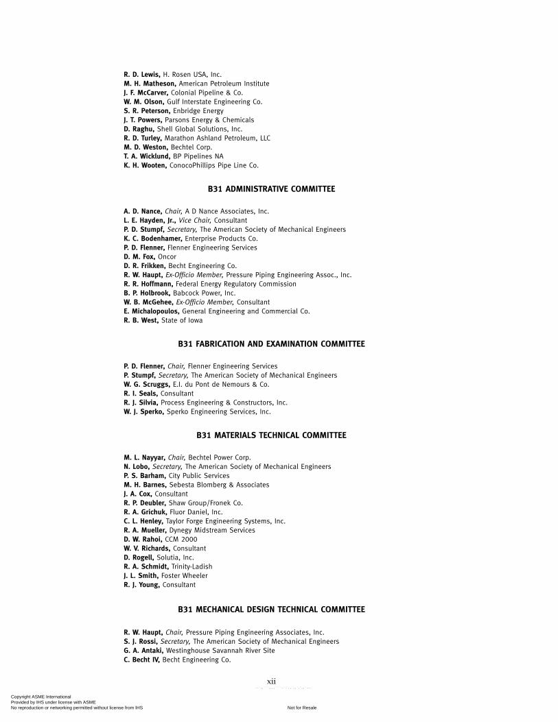
B31 ADMINISTRATIVE COMMITTEE
A. D. Nance, Chair, A D Nance Associates, Inc.L. E. Hayden, Jr., Vice Chair, ConsultantP. D. Stumpf, Secretary, The American Society of Mechanical EngineersK. C. Bodenhamer, Enterprise Products Co.P. D. Flenner, Flenner Engineering ServicesD. M. Fox, OncorD. R. Frikken, Becht Engineering Co.R. W. Haupt, Ex-Officio Member, Pressure Piping Engineering Assoc., Inc.R. R. Hoffmann, Federal Energy Regulatory CommissionB. P. Holbrook, Babcock Power, Inc.W. B. McGehee, Ex-Officio Member, ConsultantE. Michalopoulos, General Engineering and Commercial Co.R. B. West, State of Iowa
B31 FABRICATION AND EXAMINATION COMMITTEE
P. D. Flenner, Chair, Flenner Engineering ServicesP. Stumpf, Secretary, The American Society of Mechanical EngineersW. G. Scruggs, E.I. du Pont de Nemours & Co.R. I. Seals, ConsultantR. J. Silvia, Process Engineering & Constructors, Inc.W. J. Sperko, Sperko Engineering Services, Inc.
B31 MATERIALS TECHNICAL COMMITTEE
M. L. Nayyar, Chair, Bechtel Power Corp.N. Lobo, Secretary, The American Society of Mechanical EngineersP. S. Barham, City Public ServicesM. H. Barnes, Sebesta Blomberg & AssociatesJ. A. Cox, ConsultantR. P. Deubler, Shaw Group/Fronek Co.R. A. Grichuk, Fluor Daniel, Inc.C. L. Henley, Taylor Forge Engineering Systems, Inc.R. A. Mueller, Dynegy Midstream ServicesD. W. Rahoi, CCM 2000W. V. Richards, ConsultantD. Rogell, Solutia, Inc.R. A. Schmidt, Trinity-LadishJ. L. Smith, Foster WheelerR. J. Young, Consultant
B31 MECHANICAL DESIGN TECHNICAL COMMITTEE
R. W. Haupt, Chair, Pressure Piping Engineering Associates, Inc.S. J. Rossi, Secretary, The American Society of Mechanical EngineersG. A. Antaki, Westinghouse Savannah River SiteC. Becht IV, Becht Engineering Co.
xii
Copyright ASME International Provided by IHS under license with ASME
Not for ResaleNo reproduction or networking permitted without license from IHS
--`,,```,,,,````-`-`,,`,,`,`,,`---

J. P. Breen, John J. McMullen Assoc.J. P. Ellenberger, ConsultantD. J. Fetzner, BPX Alaska, Inc.J. A. Graziano, Tennessee Valley AuthorityJ. D. Hart, SSD, Inc.B. P. Holbrook, Babcock Power, Inc.W. J. Koves, UOP LLCG. Mayers, Anteon Corp.T. Q. McCawley, TQM Engineering, PCE. Michalopoulos, General Engineering and Commercial Co.J. C. Minichiello, Framatome ANPT. J. O’Grady II, Veco Alaska, Inc.A. W. Paulin, Paulin Research GroupR. A. Robleto, Robert A. RobletoM. J. Rosenfeld, Kiefner & Associates, Inc.G. Stevick, Berkeley Engineering & Research, Inc.E. A. Wais, Wais and Associates, Inc.G. E. Woods, Technip USAE. C. Rodabaugh, Honorary Member, Consultant
B31 CONFERENCE GROUP
T. A. Bell, Bonneville Power AdministrationG. Bynog, State of Texas, TDLS-Boiler DivisionR. A. Coomes, State of Kentucky, Dept. of Housing/Boiler SectionD. H. Hanrath, ConsultantC. J. Harvey, Alabama Public Service CommissionD. T. Jagger, Ohio Department of CommerceM. Kotb, Regie du Batiment du QuebecK. T. Lau, Alberta Boilers Safety AssociationR. G. Marini, New Hampshire Public Utilities CommissionI. W. Mault, Manitoba Department of LabourA. W. Meiring, Fire and Building Boiler and Pressure Vessel DivisionR. F. Mullaney, Boiler and Pressure Vessel Safety BranchP. Sher, State of ConnecticutM. E. Skarda, Department of LaborD. A. Starr, Nebraska Department of LaborD. J. Stursma, Iowa Utilities BoardR. P. Sullivan, The National Board of Boiler and Pressure Vessel InspectorsJ. E. Troppman, Division of Labor/State of Colorado Boiler InspectionsC. H. Walters, National Board of Boiler and Pressure Vessel InspectorsW. A. West, Lighthouse Assistance, Inc.T. F. Wickham, Rhode Island Department of Labor
B31 NATIONAL INTEREST REVIEW GROUP
American Pipe Fitting Association — H. ThielschAmerican Society of Heating, Refrigeration and Air Conditioning Engineers — H. R. KornblumChemical Manufacturers Association — D. R. FrikkenCopper Development Association — A. CohenDuctile Iron Pipe Research Association — T. F. StroudEdison Electric Institute — R. L. WilliamsInternational District Heating Association — G. M. Von BargenManufacturers Standardization Society of the Valve and Fittings Industry — R. A. SchmidtNational Association of Plumbing-Heating-Cooling Contractors — R. E. WhiteNational Certified Pipe Welding Bureau — D. NikpourfardNational Fire Protection Association — T. C. LemoffNational Fluid Power Association — H. G. AndersonValve Manufacturers Association — R. A. Handschumacher
xiii
Copyright ASME International Provided by IHS under license with ASME
Not for ResaleNo reproduction or networking permitted without license from IHS
--`,,```,,,,````-`-`,,`,,`,`,,`---

INTRODUCTION
The ASME B31 Code for Pressure Piping consists of a number of individually publishedSections, each an American National Standard. Hereafter, in this Introduction and in the text ofthis Code Section B31.4, where the word ‘‘Code’’ is used without specific identification, it meansthis Code Section.
The Code sets forth engineering requirements deemed necessary for safe design and construc-tion of pressure piping. While safety is the basic consideration, this factor alone will not necessarilygovern the final specifications for any piping system. The designer is cautioned that the Codeis not a design handbook; it does not do away with the need for the designer or for competentengineering judgment.
To the greatest possible extent, Code requirements for design are stated in terms of basic designprinciples and formulas. These are supplemented as necessary with specific requirements toassure uniform application of principles and to guide selection and application of piping elements.The Code prohibits designs and practices known to be unsafe and contains warnings wherecaution, but not prohibition, is warranted.
This Code Section includes(a) references to acceptable material specifications and component standards, including dimen-
sional requirements and pressure-temperature ratings(b) requirements for design of components and assemblies, including pipe supports(c) requirements and data for evaluation and limitation of stresses, reactions, and movements
associated with pressure, temperature changes, and other forces(d) guidance and limitations on the selection and application of materials, components, and
joining methods(e) requirements for the fabrication, assembly, and erection of piping(f) requirements for examination, inspection, and testing of piping(g) procedures for operation and maintenance that are essential to public safety(h) provisions for protecting pipelines from external corrosion and internal corrosion/erosionIt is intended that this Edition of Code Section B31.4 and any subsequent Addenda not be
retroactive. Unless agreement is specifically made between contracting parties to use anotherissue, or the regulatory body having jurisdiction imposes the use of another issue, the latestEdition and Addenda issued at least 6 months prior to the original contract date for the firstphase of activity covering a piping system or systems shall be the governing document for alldesign, materials, fabrication, erection, examination, and testing for the piping until the comple-tion of the work and initial operation.
Users of this Code are cautioned against making use of Code revisions without assurance thatthey are acceptable to the proper authorities in the jurisdiction where the piping is to be installed.
Code users will note that paragraphs in the Code are not necessarily numbered consecutively.Such discontinuities result from following a common outline, insofar as practicable, for all CodeSections. In this way, corresponding material is correspondingly numbered in most Code Sections,thus facilitating reference by those who have occasion to use more than one Section.
The Code is under the direction of ASME Committee B31, Code for Pressure Piping, which isorganized and operates under procedures of The American Society of Mechanical Engineerswhich have been accredited by the American National Standards Institute. The Committee is acontinuing one and keeps all Code Sections current with new developments in materials, construc-tion, and industrial practice. Addenda are issued periodically. New editions are published atintervals of 3 to 5 years.
When no Section of the ASME Code for Pressure Piping specifically covers a piping system,at his discretion the user may select any Section determined to be generally applicable. However,it is cautioned that supplementary requirements to the Section chosen may be necessary to providefor a safe piping system for the intended application. Technical limitations of the various Sections,legal requirements, and possible applicability of other codes or standards are some of the factors
xiv
Copyright ASME International Provided by IHS under license with ASME
Not for ResaleNo reproduction or networking permitted without license from IHS
--`,,```,,,,````-`-`,,`,,`,`,,`---

to be considered by the user in determining the applicability of any Section of this Code.The Committee has established an orderly procedure to consider requests for interpretation
and revision of Code requirements. To receive consideration, inquiries must be in writing andmust give full particulars (see Mandatory Appendix covering preparation of technical inquiries).
The approved reply to an inquiry will be sent directly to the inquirer. In addition, the questionand reply will be published as part of an Interpretation Supplement issued to the applicableCode Section.
A Case is the prescribed form of reply to an inquiry when study indicates that the Codewording needs clarification or when the reply modifies existing requirements of the Code orgrants permission to use new materials or alternative constructions. Proposed Cases are publishedin Mechanical Engineering for public review. In addition, the Case will be published on the B31.4web site at http://www.asme.org/codes/.
A Case is normally issued for a limited period, after which it may be renewed, incorporatedin the Code, or allowed to expire if there is no indication of further need for the requirementscovered by the Case. However, the provisions of a Case may be used after its expiration orwithdrawal, providing the Case was effective on the original contract date or was adopted beforecompletion of the work, and the contracting parties agree to its use.
Materials are listed in the stress tables only when sufficient usage in piping within the scopeof the Code has been shown. Materials may be covered by a Case. Requests for listing shallinclude evidence of satisfactory usage and specific data to permit establishment of allowablestresses, maximum and minimum temperature limits, and other restrictions. Additional criteriacan be found in the guidelines for addition of new materials in the ASME Boiler and PressureVessel Code, Section II and Section VIII, Division 1, Appendix B. (To develop usage and gainexperience, unlisted materials may be used in accordance with para. 423.1.)
Requests for interpretation and suggestions for revision should be addressed to the Secretary,ASME B31 Committee, Three Park Avenue, New York, NY 10016.
xv
Copyright ASME International Provided by IHS under license with ASME
Not for ResaleNo reproduction or networking permitted without license from IHS
--`,,```,,,,````-`-`,,`,,`,`,,`---

ASME B31.4-2006SUMMARY OF CHANGES
Following approval by the B31 Committee and ASME, and after public review, ASME B31.4-2006was approved by the American National Standards Institute on January 5, 2006.
ASME B31.4-2006 includes editorial changes, revisions, and corrections identified by a marginnote, (06), placed next to the affected area.
Page Location Change
4–6 400.2 Definitions for employer, in-line inspectiontools, mainline pipelines, and returninterval added
8–12 402.3.1 Equations and nomenclature for Srevised
Table 402.3.1(a) Allowable Stress Value S for ASTM A 333corrected by errata
402.3.1(h) Added
402.6 Added
13 404.1.1(b) Nomenclature for t revised
22 406.1.1(d) Added
406.2.1(d) Added
406.2.2 Last sentence added
406.2.3(b) Revised
406.5 Last sentence added
23 407.1(d) Added
30 422.2 Added
422.6.1 Revised
422.7 Added
31 423.1(b) Revised
423.2.3 Revised
32, 33 Table 423.1 Revised
36 Table 426.1 Revised
37 434.2 (1) Title revised(2) Revised in its entirety
434.4 Revised
38 434.7.1(e) Added
39 Table 434.6(a) Revised in its entirety
434.8.3(b) Revised in its entirety
40, 41 484.8.3(e) Revised
xvi
Copyright ASME International Provided by IHS under license with ASME
Not for ResaleNo reproduction or networking permitted without license from IHS
--`,,```,,,,````-`-`,,`,,`,`,,`---

Page Location Change
434.8.3(g) Last sentence added
434.8.5(a)(3) Revised
43, 44 Fig. 434.8.6(a)-(2) Notes added by errata
47 434.13.5 Added
48 434.17.4 Added
52 436.5.2(d) Added
53 437.1.4(b) Reference in first sentence corrected byerrata
437.1.5 Added
57–65 450.2(l) Added
451.4 Revised in its entirety
451.5(a) Second sentence revised
451.6 Revised in its entirety
Fig. 451.6.2(a)(2)(d)(1) Added
Fig. 451.6.2(a)(2)(d)(2) Added
Table 451.6.2(b)-1 Added
Table 451.6.2(b)-2 Added
66 451.11 Added
452.1(b) Revised in its entirety
71 461.1.2(f) First sentence revised
461.1.2(i) Added
75, 76 A400.2 Definition of return interval deleted
84 A434.4 Deleted
91, 92 Nonmandatory API RP 1130 addedAppendix A
96 Nonmandatory AddedAppendix C
xvii
Copyright ASME International Provided by IHS under license with ASME
Not for ResaleNo reproduction or networking permitted without license from IHS
--`,,```,,,,````-`-`,,`,,`,`,,`---

xviii
Copyright ASME International Provided by IHS under license with ASME
Not for ResaleNo reproduction or networking permitted without license from IHS
--`,,```,,,,````-`-`,,`,,`,`,,`---

ASME B31.4-2006
Chapter IScope and Definitions
400 GENERAL STATEMENTS
(a) This Liquid Transportation Systems Code is oneof several sections of the ASME Code for Pressure Pip-ing, B31. This Section is published as a separate docu-ment for convenience. This Code applies tohydrocarbons, liquid petroleum gas, anhydrous ammo-nia, alcohols, and carbon dioxide. Throughout this Codethese systems will be referred to as Liquid PipelineSystems.
(b) The requirements of this Code are adequate forsafety under conditions normally encountered in theoperation of liquid pipeline systems. Requirements forall abnormal or unusual conditions are not specificallyprovided for, nor are all details of engineering and con-struction prescribed. All work performed within theScope of this Code shall comply with the safety stan-dards expressed or implied.
(c) The primary purpose of this Code is to establishrequirements for safe design, construction, inspection,testing, operation, and maintenance of liquid pipelinesystems for protection of the general public andoperating company personnel as well as for reasonableprotection of the piping system against vandalism andaccidental damage by others and reasonable protectionof the environment.
(d) This Code is concerned with employee safety tothe extent that it is affected by basic design, qualityof materials and workmanship, and requirements forconstruction, inspection, testing, operation, and mainte-nance of liquid pipeline systems. Existing industrialsafety regulations pertaining to work areas, safe workpractices, and safety devices are not intended to be sup-planted by this Code.
(e) The designer is cautioned that the Code is not adesign handbook. The Code does not do away with theneed for the engineer or competent engineering judg-ment. The specific design requirements of the Code usu-ally revolve around a simplified engineering approachto a subject. It is intended that a designer capable ofapplying more complete and rigorous analysis to specialor unusual problems shall have latitude in the develop-ment of such designs and the evaluation of complex orcombined stresses. In such cases the designer is responsi-ble for demonstrating the validity of his approach.
(f) This Code shall not be retroactive or construedas applying to piping systems installed before date ofissuance shown on document title page insofar as
1
design, materials, construction, assembly, inspection,and testing are concerned. It is intended, however, thatthe provisions of this Code shall be applicable within 6months after date of issuance to the relocation, replace-ment, and uprating or otherwise changing existing pip-ing systems; and to the operation, maintenance, andcorrosion control of new or existing piping systems.After Code revisions are approved by ASME and ANSI,they may be used by agreement between contractingparties beginning with the date of issuance. Revisionsbecome mandatory or minimum requirements for newinstallations 6 months after date of issuance except forpiping installations or components contracted for orunder construction prior to the end of the 6 monthperiod.
(g) The users of this Code are advised that in someareas legislation may establish governmental jurisdic-tion over the subject matter covered by this Code andare cautioned against making use of revisions that areless restrictive than former requirements without havingassurance that they have been accepted by the properauthorities in the jurisdiction where the piping is tobe installed. The Department of Transportation, UnitedStates of America, rules governing the transportationby pipeline in interstate and foreign commerce of petro-leum, petroleum products, and liquids such as anhy-drous ammonia or carbon dioxide are prescribed underPart 195 — Transportation of Hazardous Liquids byPipeline, Title 49 — Transportation, Code of FederalRegulations.
400.1 Scope
400.1.1 This Code prescribes requirements for thedesign, materials, construction, assembly, inspection,and testing of piping transporting liquids such as crudeoil, condensate, natural gasoline, natural gas liquids,liquefied petroleum gas, carbon dioxide, liquid alcohol,liquid anhydrous ammonia, and liquid petroleum prod-ucts between producers’ lease facilities, tank farms, nat-ural gas processing plants, refineries, stations, ammoniaplants, terminals (marine, rail, and truck), and otherdelivery and receiving points. (See Figs. 400.1.1 and400.1.2.)
Piping consists of pipe, flanges, bolting, gaskets,valves, relief devices, fittings, and the pressure con-taining parts of other piping components. It alsoincludes hangers and supports, and other equipmentitems necessary to prevent overstressing the pressure
Copyright ASME International Provided by IHS under license with ASME
Not for ResaleNo reproduction or networking permitted without license from IHS
--`,,```,,,,````-`-`,,`,,`,`,,`---

ASME B31.4-2006 PIPELINE TRANSPORTATION SYSTEMS FORLIQUID HYDROCARBONS AND OTHER LIQUIDS
Fig. 400.1.1 Diagram Showing Scope of ASME B31.4 Excluding Carbon Dioxide Pipeline Systems(See Fig. 400.1.2)
2
Copyright ASME International Provided by IHS under license with ASME
Not for ResaleNo reproduction or networking permitted without license from IHS
--`,,```,,,,````-`-`,,`,,`,`,,`---

PIPELINE TRANSPORTATION SYSTEMS FOR ASME B31.4-2006LIQUID HYDROCARBONS AND OTHER LIQUIDS
Fig. 400.1.2 Diagram Showing Scope of ASME B31.4 for Carbon Dioxide Pipeline Systems
3
Copyright ASME International Provided by IHS under license with ASME
Not for ResaleNo reproduction or networking permitted without license from IHS
--`,,```,,,,````-`-`,,`,,`,`,,`---

ASME B31.4-2006 PIPELINE TRANSPORTATION SYSTEMS FORLIQUID HYDROCARBONS AND OTHER LIQUIDS
containing parts. It does not include support structuressuch as frames of buildings, stanchions, or foundations,or any equipment such as defined in para. 400.1.2(b).
Requirements for offshore pipelines are found inChapter IX.
Also included within the scope of this Code are(a) primary and associated auxiliary liquid petroleum
and liquid anhydrous ammonia piping at pipeline termi-nals (marine, rail, and truck), tank farms, pump stations,pressure reducing stations, and metering stations,including scraper traps, strainers, and prover loops
(b) storage and working tanks, including pipe-typestorage fabricated from pipe and fittings, and pipinginterconnecting these facilities
(c) liquid petroleum and liquid anhydrous ammoniapiping located on property which has been set aside forsuch piping within petroleum refinery, natural gasoline,gas processing, ammonia, and bulk plants
(d) those aspects of operation and maintenance ofLiquid Pipeline Systems relating to the safety and pro-tection of the general public, operating company person-nel, environment, property, and the piping systems [seeparas. 400(c) and (d)]
400.1.2 This Code does not apply to(a) auxiliary piping, such as water, air, steam, lubricat-
ing oil, gas, and fuel(b) pressure vessels, heat exchangers, pumps, meters,
and other such equipment including internal piping andconnections for piping except as limited by para.423.2.4(b)
(c) piping designed for internal pressures(1) at or below 15 psi (1 bar) gage pressure regard-
less of temperature(2) above 15 psi (1 bar) gage pressure if design
temperature is below minus 20°F (−30°C) or above 250°F(120°C)
(d) casing, tubing, or pipe used in oil wells, wellheadassemblies, oil and gas separators, crude oil productiontanks, and other producing facilities
(e) petroleum refinery, natural gasoline, gas pro-cessing, ammonia, carbon dioxide processing, and bulkplant piping, except as covered under para. 400.1.1(c)
(f) gas transmission and distribution piping(g) the design and fabrication of proprietary items of
equipment, apparatus, or instruments, except as limitedby para. 423.2.4(b)
(h) ammonia refrigeration piping systems providedfor in ASME B31.5, Refrigeration Piping Code
(i) carbon dioxide gathering and field distributionsystem
4
400.2 DefinitionsSome of the more common terms relating to piping
are defined below.1
accidental loads: any unplanned load or combination ofunplanned loads caused by human intervention or natu-ral phenomena.
blunt imperfection: an imperfection characterized bysmoothly contoured variations in wall thickness.2
breakaway coupling: a component installed in the pipelineto allow the pipeline to separate when a predeterminedaxial load is applied to the coupling.
buckle: a condition where the pipeline has undergonesufficient plastic deformation to cause permanent wrin-kling in the pipe wall or excessive cross-sectional defor-mation caused by loads acting alone or in combinationwith hydrostatic pressure.
carbon dioxide: a fluid consisting predominantly of car-bon dioxide compressed above its critical pressure and,for the purpose of this Code, shall be considered to bea liquid.
cold springing: deliberate deflection of piping, within itsyield strength, to compensate for anticipated thermalexpansion.
column buckling: buckling of a beam or pipe under com-pressive axial load in which loads cause unstable lateraldeflection, also referred to as upheaval buckling.
connectors: component, except flanges, used for the pur-pose of mechanically joining two sections of pipe.
defect: an imperfection of sufficient magnitude to warrantrejection.
design life: a period of time used in design calculations,selected for the purpose of verifying that a replaceableor permanent component is suitable for the anticipatedperiod of service. Design life does not pertain to the lifeof the pipeline system because a properly maintainedand protected pipeline system can provide liquid trans-portation service indefinitely.
employer: the owner, manufacturer, fabricator, contractor,assembler, or installer responsible for the welding, braz-ing, and NDE performed by his organization, includingprocedure and performance qualifications.
engineering design: detailed design developed fromoperating requirements and conforming to Coderequirements, including all necessary drawings andspecifications, governing a piping installation.
general corrosion: uniform or gradually varying loss ofwall thickness over an area.
1 Welding terms which agree with AWS Standard A3.0 aremarked with an asterisk (*). For welding terms used in this Codebut not shown here, definitions in accordance with AWS A3.0apply.
2 Sharp imperfections may be rendered blunt by grinding, butthe absence of a sharp imperfection must be verified by visual andnondestructive examination.
(06)
Copyright ASME International Provided by IHS under license with ASME
Not for ResaleNo reproduction or networking permitted without license from IHS
--`,,```,,,,````-`-`,,`,,`,`,,`---

PIPELINE TRANSPORTATION SYSTEMS FOR ASME B31.4-2006LIQUID HYDROCARBONS AND OTHER LIQUIDS
girth weld: a complete circumferential butt weld joiningpipe or components.
imperfection: a discontinuity or irregularity which isdetected by inspection.
in-line inspection tools: any instrumented device or vehi-cle that records data and uses nondestructive test meth-ods or other techniques to inspect the pipeline from theinside. Also known as intelligent or smart pig.
internal design pressure: internal pressure used in calcula-tions or analysis for pressure design of a piping compo-nent (see para. 401.2.2).
liquefied petroleum gas(es) (LPG): liquid petroleum com-posed predominantly of the following hydrocarbons,either by themselves or as mixtures: butane (normalbutane or isobutane), butylene (including isomers), pro-pane, propylene, and ethane.
liquid alcohol: any of a group of organic compounds con-taining only hydrogen, carbon, and one or morehydroxyl radicals which will remain liquid in a movingstream in a pipeline.
liquid anhydrous ammonia: a compound formed by thecombination of the two gaseous elements, nitrogen andhydrogen, in the proportion of one part of nitrogen tothree parts of hydrogen, by volume, compressed to aliquid state.
mainline pipelines: all in-line pipeline pipes, fittings,bends, elbows, check valves, and block valves betweenscraper traps.
maximum steady state operating pressure: maximum pres-sure (sum of static head pressure, pressure required toovercome friction losses, and any back pressure) at anypoint in a piping system when the system is operatingunder steady state conditions.
miter: two or more straight sections of pipe matched andjoined on a line bisecting the angle of junction so as toproduce a change in direction.
nominal pipe size (NPS): see ASME B36.10M p. 1 for defi-nition.
operating company: owner or agent currently responsiblefor the design, construction, inspection, testing, opera-tion, and maintenance of the piping system.
petroleum: crude oil, condensate, natural gasoline, natu-ral gas liquids, liquefied petroleum gas, and liquid petro-leum products.
pipe: a tube, usually cylindrical, used for conveying afluid or transmitting fluid pressure, normally desig-nated ‘‘pipe’’ in the applicable specification. It alsoincludes any similar component designated as ‘‘tubing’’used for the same purpose. Types of pipe, according tothe method of manufacture, are defined as follows.
(a) electric resistance welded pipe: pipe produced inindividual lengths or in continuous lengths from coiled
5
skelp, having a longitudinal or spiral butt joint whereincoalescence is produced by the heat obtained from resist-ance of the pipe to the flow of electric current in a circuitof which the pipe is a part, and by the application ofpressure.
(b) furnace lap welded pipe: pipe having a longitudinallap joint made by the forge welding process whereincoalescence is produced by heating the preformed tubeto welding temperature and passing it over a mandrellocated between two welding rolls which compress andweld the overlapping edges.
(c) furnace butt welded pipe(1) furnace butt welded pipe, bell welded: pipe pro-
duced in individual lengths from cut-length skelp, hav-ing its longitudinal butt joint forge welded by themechanical pressure developed in drawing the furnaceheated skelp through a cone-shaped die (commonlyknown as the “welding bell”) which serves as a com-bined forming and welding die.
(2) furnace butt welded pipe, continuous welded: pipeproduced in continuous lengths from coiled skelp andsubsequently cut into individual lengths, having its lon-gitudinal butt joint forge welded by the mechanical pres-sure developed in rolling the hot formed skelp througha set of round pass welding rolls.
(d) electric fusion welded pipe: pipe having a longitudi-nal or spiral butt joint wherein coalescence is producedin the preformed tube by manual or automatic electricarc welding. The weld may be single or double and maybe made with or without the use of filler metal. Spiralwelded pipe is also made by the electric fusion weldedprocess with either a lap joint or a lock-seam joint.
(e) electric flash welded pipe: pipe having a longitudinalbutt joint wherein coalescence is produced simultane-ously over the entire area of abutting surfaces by the heatobtained from resistance to the flow of electric currentbetween the two surfaces, and by the application ofpressure after heating is substantially completed. Flash-ing and upsetting are accompanied by expulsion ofmetal from the joint.
(f) double submerged arc welded pipe: pipe having a lon-gitudinal or spiral butt joint produced by at least twopasses, one of which is on the inside of the pipe. Coales-cence is produced by heating with an electric arc or arcsbetween the bare metal electrode or electrodes and thework. The welding is shielded by a blanket of granular,fusible material on the work. Pressure is not used andfiller metal for the inside and outside welds is obtainedfrom the electrode or electrodes.
(g) seamless pipe: pipe produced by piercing a billetfollowed by rolling or drawing, or both.
(h) electric induction welded pipe: pipe produced inindividual lengths or in continuous lengths from coiledskelp having a longitudinal or spiral butt joint whereincoalescence is produced by the heat obtained from resist-ance of the pipe to induced electric current, and by appli-cation of pressure.
Copyright ASME International Provided by IHS under license with ASME
Not for ResaleNo reproduction or networking permitted without license from IHS
--`,,```,,,,````-`-`,,`,,`,`,,`---

ASME B31.4-2006 PIPELINE TRANSPORTATION SYSTEMS FORLIQUID HYDROCARBONS AND OTHER LIQUIDS
pipe nominal wall thickness: the wall thickness listed inapplicable pipe specifications or dimensional standardsincluded in this Code by reference. The listed wall thick-ness dimension is subject to tolerances as given in thespecification or standard.
pipe supporting elements: pipe supporting elements con-sist of fixtures and structural attachments as follows.
(a) fixtures: fixtures include elements which transferthe load from the pipe or structural attachment to thesupporting structure or equipment. They include hang-ing type fixtures such as hanger rods, spring hangers,sway braces, counterweights, turnbuckles, struts, chains,guides and anchors, and bearing type fixtures such assaddles, bases, rollers, brackets, and sliding supports.
(b) structural attachments: structural attachmentsinclude elements which are welded, bolted, or clampedto the pipe, such as clips, lugs, rings, clamps, clevises,straps, and skirts.
pressure: unless otherwise stated, pressure is expressedin pounds per square inch (bar) above atmospheric pres-sure, i.e., gage pressure as abbreviated psig (bar).
return interval: statistically determined time intervalbetween successive events of design environmental con-ditions being equaled or exceeded.
shall: “shall” or “shall not” is used to indicate that aprovision is mandatory.
should: “should” or “it is recommended” is used to indi-cate that a provision is not mandatory but recommendedas good practice.
soil liquefaction: a soil condition, typically caused bydynamic cyclic loading (e.g., earthquake, waves) wherethe effective shear strength of the soil is reduced suchthat the soil exhibits the properties of a liquid.
span: a section of pipe that is unsupported
temperatures: are expressed in degrees Fahrenheit (°F)unless otherwise stated.
weight coating: any coating applied to the pipeline forthe purpose of increasing the pipeline specific gravity.
arc welding*: a group of welding processes whereincoalescence is produced by heating with an electric arcor arcs, with or without the application of pressure andwith or without the use of filler metal.
automatic welding*: welding with equipment which per-forms the entire welding operation without constantobservation and adjustment of the controls by an opera-tor. The equipment may or may not perform the loadingand unloading of the work.
fillet weld*: a weld of approximately triangular cross sec-tion joining two surfaces approximately at right anglesto each other in a lap joint, tee joint, or corner joint.
6
full fillet weld*: a fillet weld whose size is equal to thethickness of the thinner member joined.
gas welding*: a group of welding processes whereincoalescence is produced by heating with a gas flame orflames, with or without the application of pressure, andwith or without the use of filler metal.
gas metal arc welding*: an arc welding process whereincoalescence is produced by heating with an electric arcbetween a filler metal (consumable) electrode and thework. Shielding is obtained from a gas, a gas mixture(which may contain an inert gas), or a mixture of a gasand a flux. (This process has sometimes been called Migwelding or CO2 welding.)
gas tungsten arc welding*: an arc welding process whereincoalescence is produced by heating with an electric arcbetween a single tungsten (nonconsumable) electrodeand the work. Shielding is obtained from a gas or gasmixture (which may contain an inert gas). Pressure mayor may not be used and filler metal may or may notbe used. (This process has sometimes been called Tigwelding.)
semiautomatic arc welding*: arc welding with equipmentwhich controls only the filler metal feed. The advanceof the welding is manually controlled.
shielded metal arc welding*: an arc welding processwherein coalescence is produced by heating with anelectric arc between a covered metal electrode and thework. Shielding is obtained from decomposition of theelectrode covering. Pressure is not used and filler metalis obtained from the electrode.
submerged arc welding*: an arc welding process whereincoalescence is produced by heating with an electric arcor arcs between a bare metal electrode or electrodesand the work. The welding is shielded by a blanket ofgranular, fusible material on the work. Pressure is notused, and filler metal is obtained from the electrode andsometimes from a supplementary welding rod.
tack weld*: a weld made to hold parts of a weldment inproper alignment until subsequent welds are made
weld*: a localized coalescence of metal wherein coales-cence is produced by heating to suitable temperatures,with or without the application of pressure, and withor without the use of filler metal. The filler metal shallhave a melting point approximately the same as the basemetal.
welder*: one who is capable of performing a manual orsemiautomatic welding operation.
welding operator*: one who operates machine or auto-matic welding equipment.
welding procedures*: the detailed methods and practicesincluding joint welding procedures involved in the pro-duction of a weldment.
Copyright ASME International Provided by IHS under license with ASME
Not for ResaleNo reproduction or networking permitted without license from IHS
--`,,```,,,,````-`-`,,`,,`,`,,`---

ASME B31.4-2006
Chapter IIDesign
PART 1CONDITIONS AND CRITERIA
401 DESIGN CONDITIONS
401.1 General
Paragraph 401 defines the pressures, temperatures,and various forces applicable to the design of pipingsystems within the scope of this Code. It also takes intoaccount considerations that shall be given to ambientand mechanical influences and various loadings.
401.2 Pressure
401.2.2 Internal Design Pressure. The piping com-ponent at any point in the piping system shall bedesigned for an internal design pressure which shallnot be less than the maximum steady state operatingpressure at that point, or less than the static head pres-sure at that point with the line in a static condition. Themaximum steady state operating pressure shall be thesum of the static head pressure, pressure required toovercome friction losses, and any required back pres-sure. Credit may be given for hydrostatic external pres-sure, in the appropriate manner, in modifying theinternal design pressure for use in calculations involvingthe pressure design of piping components (see para.404.1.3). Pressure rise above maximum steady stateoperating pressure due to surges and other variationsfrom normal operations is allowed in accordance withpara. 402.2.4.
401.2.3 External Design Pressure. The piping com-ponent shall be designed to withstand the maximumpossible differential between external and internal pres-sures to which the component will be exposed.
401.3 Temperature
401.3.1 Design Temperature. The design tempera-ture is the metal temperature expected in normal opera-tion. It is not necessary to vary the design stress formetal temperatures between −20°F (−30°C) and 250°F(120°C). However, some of the materials conforming tospecifications approved for use under this Code maynot have properties suitable for the lower portion of thetemperature band covered by this Code. Engineers arecautioned to give attention to the low temperature prop-erties of the materials used for facilities to be exposedto unusually low ground temperatures, low atmospherictemperatures, or transient operating conditions.
7
401.4 Ambient Influences
401.4.2 Fluid Expansion Effects. Provision shall bemade in the design either to withstand or to relieveincreased pressure caused by the heating of static fluidin a piping component.
401.5 Dynamic Effects
401.5.1 Impact. Impact forces caused by eitherexternal or internal conditions shall be considered in thedesign of piping systems.
401.5.2 Wind. The effect of wind loading shall beprovided for in the design of suspended piping.
401.5.3 Earthquake. Consideration in the designshall be given to piping systems located in regions whereearthquakes are known to occur.
401.5.4 Vibration. Stress resulting from vibrationor resonance shall be considered and provided for inaccordance with sound engineering practice.
401.5.5 Subsidence. Consideration in the designshall be given to piping systems located in regions wheresubsidence is known to occur.
401.5.6 Waves and Currents. The effects of wavesand currents shall be provided for in the design of pipe-lines across waterways.
401.6 Weight Effects
The following weight effects combined with loads andforces from other causes shall be taken into account inthe design of piping that is exposed, suspended, or notsupported continuously.
401.6.1 Live Loads. Live loads include the weightof the liquid transported and any other extraneous mate-rials such as ice or snow that adhere to the pipe. Theimpact of wind, waves, and currents are also consideredlive loads.
401.6.2 Dead Loads. Dead loads include the weightof the pipe, components, coating, backfill, and unsup-ported attachments to the piping.
401.7 Thermal Expansion and Contraction Loads
Provisions shall be made for the effects of thermalexpansion and contraction in all piping systems.
Copyright ASME International Provided by IHS under license with ASME
Not for ResaleNo reproduction or networking permitted without license from IHS
--`,,```,,,,````-`-`,,`,,`,`,,`---

ASME B31.4-2006 PIPELINE TRANSPORTATION SYSTEMS FORLIQUID HYDROCARBONS AND OTHER LIQUIDS
401.8 Relative Movement of Connected Components
The effect of relative movement of connected compo-nents shall be taken into account in design of pipingand pipe supporting elements.
402 DESIGN CRITERIA
402.1 General
Paragraph 402 pertains to ratings, stress criteria,design allowances, and minimum design values, andformulates the permissible variations to these factorsused in the design of piping systems within the scopeof this Code.
The design requirements of this Code are adequatefor public safety under conditions usually encounteredin piping systems within the scope of this Code, includ-ing lines within villages, towns, cities, and industrialareas. However, the design engineer shall provide rea-sonable protection to prevent damage to the pipelinefrom unusual external conditions which may be encoun-tered in river crossings, inland coastal water areas,bridges, areas of heavy traffic, long self-supported spans,unstable ground, vibration, weight of special attach-ments, or forces resulting from abnormal thermal condi-tions. Some of the protective measures which the designengineer may provide are encasing with steel pipe oflarger diameter, adding concrete protective coating,increasing the wall thickness, lowering the line to agreater depth, or indicating the presence of the line withadditional markers.
402.2 Pressure–Temperature Ratings for PipingComponents
402.2.1 Components Having Specific Ratings.Within the metal temperature limits of −20°F (−30°C)to 250°F (120°C), pressure ratings for components shallconform to those stated for 100°F (40°C) in materialstandards listed in Table 423.1. The nonmetallic trim,packing, seals, and gaskets shall be made of materialswhich are not injuriously affected by the fluid in thepiping system and shall be capable of withstanding thepressures and temperatures to which they will be sub-jected in service. Low temperatures due to pressurereduction situations, such as blow downs and otherevents, shall be considered when designing carbon diox-ide pipelines.
402.2.2 Ratings — Components Not Having SpecificRatings. Piping components not having establishedpressure ratings may be qualified for use as specifiedin paras. 404.7 and 423.1(b).
402.2.3 Normal Operating Conditions. For normaloperation the maximum steady state operating pressureshall not exceed the internal design pressure and pres-sure ratings for the components used.
8
402.2.4 Ratings — Allowance for Variations From Nor-mal Operations. Surge pressures in a liquid pipelineare produced by a change in the velocity of the movingstream that results from shutting down of a pump sta-tion or pumping unit, closing of a valve, or blockage ofthe moving stream.
Surge pressure attenuates (decreases in intensity) asit moves away from its point of origin.
Surge calculations shall be made, and adequate con-trols and protective equipment shall be provided, sothat the level of pressure rise due to surges and othervariations from normal operations shall not exceed theinternal design pressure at any point in the piping sys-tem and equipment by more than 10%.
402.2.5 Ratings — Considerations for Different Pres-sure Conditions. When two lines that operate at differ-ent pressure conditions are connected, the valvesegregating the two lines shall be rated for the moresevere service condition. When a line is connected to apiece of equipment which operates at a higher pressurecondition than that of the line, the valve segregating theline from the equipment shall be rated for at least theoperating condition of the equipment. The pipingbetween the more severe conditions and the valve shallbe designed to withstand the operating conditions ofthe equipment or piping to which it is connected.
402.3 Allowable Stresses and Other Stress Limits
402.3.1 Allowable Stress Values(a) The allowable stress value S to be used for design
calculations in para. 404.1.2 for new pipe of known speci-fication shall be established as follows:
S p F � E � specified minimumyield strength of the pipe, psi (MPa)
whereE p weld joint factor (see para. 402.4.3 and
Table 402.4.3)F p design factor based on nominal wall thickness.
In setting design factor, due consideration hasbeen given to and allowance has been madefor the underthickness tolerance and maximumallowable depth of imperfections provided forin the specifications approved by the Code. Thevalue of F used in this Code shall be not greaterthan 0.72.
Table 402.3.1(a) is a tabulation of examples of allow-able stresses for reference use in transportation pipingsystems within the scope of this Code, for F p 0.72.
(b) The allowable stress value S to be used for designcalculations in para. 404.1.2 for used (reclaimed) pipeof known specification shall be in accordance with (a)above and limitations in para. 405.2.1(b).
(c) The allowable stress value S to be used for designcalculations in para. 404.1.2 for new or used (reclaimed)
(06)
Copyright ASME International Provided by IHS under license with ASME
Not for ResaleNo reproduction or networking permitted without license from IHS
--`,,```,,,,````-`-`,,`,,`,`,,`---

PIPELINE TRANSPORTATION SYSTEMS FOR ASME B31.4-2006LIQUID HYDROCARBONS AND OTHER LIQUIDS
Table 402.3.1(a) Tabulation of Examples of Allowable Stresses for Reference Use in Piping SystemsWithin the Scope of This Code
Specified Min. Allowable Stress Value, S,Yield Strength, −20°F to 250°F (−30°C to 120°C),
Specification Grade psi (MPa) Weld Joint Factor, E psi (MPa)
Seamless
API 5L A25 25,000 (172) 1.00 18,000 (124)API 5L, ASTM A 53, ASTM A 106 A 30,000 (207) 1.00 21,600 (149)API 5L, ASTM A 53, ASTM A 106 B 35,000 (241) 1.00 25,200 (174)
API 5L X42 42,000 (289) 1.00 30,250 (208)API 5L X46 46,000 (317) 1.00 33,100 (228)
API 5L X52 52,000 (358) 1.00 37,450 (258)API 5L X56 56,000 (386) 1.00 40,300 (278)API 5L X60 60,000 (413) 1.00 43,200 (298)
API 5L X65 65,000 (448) 1.00 46,800 (323)API 5L X70 70,000 (482) 1.00 50,400 (347)API 5L X80 80,000 (551) 1.00 57,600 (397)
ASTM A 106 C 40,000 (278) 1.00 28,800 (199)ASTM A 333 6 35,000 (241) 1.00 25,200 (174)ASTM A 524 I 35,000 (241) 1.00 25,200 (174)ASTM A 524 H 30,000 (207) 1.00 21,600 (149)
Furnace Butt Welded, Continuous Welded
ASTM A 53 . . . 25,000 (172) 0.60 10,800 (74)API 5L Classes I and II A25 25,000 (172) 0.60 10,800 (74)
Electric Resistance Welded and Electric Flash Welded
API 5L A25 25,000 (172) 1.00 18,000 (124)API 5L, ASTM A 53, ASTM A 135 A 30,000 (207) 1.00 21,600 (149)API 5L, ASTM A 53, ASTM A 135 B 35,000 (241) 1.00 25,200 (174)
API 5L X42 42,000 (289) 1.00 30,250 (208)API 5L X46 46,000 (317) 1.00 33,100 (228)
API 5L X52 52,000 (358) 1.00 37,450 (258)API 5L X56 56,000 (386) 1.00 40,300 (279)API 5L X60 60,000 (413) 1.00 43,200 (297)
API 5L X65 65,000 (448) 1.00 46,800 (323)API 5L X70 70,000 (482) 1.00 50,400 (347)API 5L X80 80,000 (551) 1.00 57,600 (397)
ASTM A 333 6 35,000 (241) 1.00 25,000 (174)
Electric Fusion Welded
ASTM A 134 . . . . . . 0.80 . . .ASTM A 139 A 30,000 (207) 0.80 17,300 (119)ASTM A 139 B 35,000 (241) 0.80 20,150 (139)
ASTM A 671 . . . Note (1) 1.00 [Notes (2), (3)] . . .ASTM A 671 . . . Note (1) 0.70 [Note (4)] . . .ASTM A 672 . . . Note (1) 1.00 [Notes (2), (3)] . . .ASTM A 672 . . . Note (1) 0.80 [Note (4)] . . .
Submerged Arc Welded
API 5L A 30,000 (207) 1.00 21,600 (149)API 5L B 35,000 (241) 1.00 25,200 (174)
API 5L X42 42,000 (289) 1.00 30,250 (208)API 5L X46 46,000 (317) 1.00 33,100 (228)
9
(06)
Copyright ASME International Provided by IHS under license with ASME
Not for ResaleNo reproduction or networking permitted without license from IHS
--`,,```,,,,````-`-`,,`,,`,`,,`---
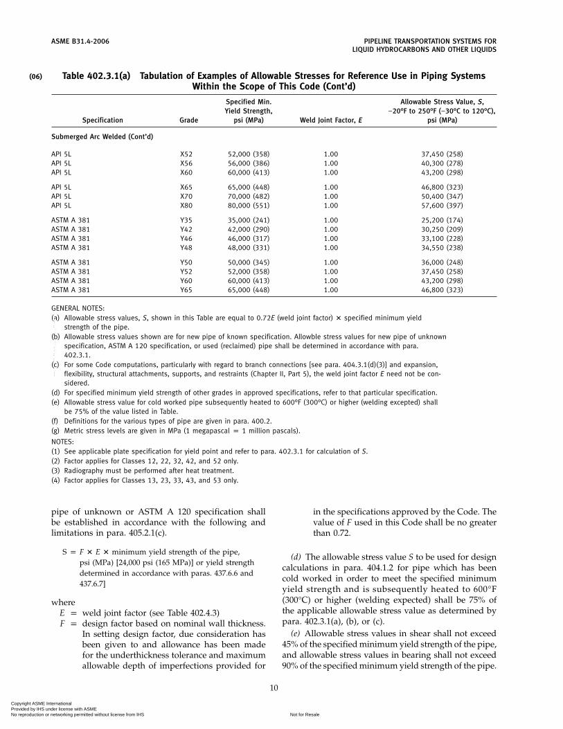
(06)
ASME B31.4-2006 PIPELINE TRANSPORTATION SYSTEMS FORLIQUID HYDROCARBONS AND OTHER LIQUIDS
Table 402.3.1(a) Tabulation of Examples of Allowable Stresses for Reference Use in Piping SystemsWithin the Scope of This Code (Cont’d)
Specified Min. Allowable Stress Value, S,Yield Strength, −20°F to 250°F (−30°C to 120°C),
Specification Grade psi (MPa) Weld Joint Factor, E psi (MPa)
Submerged Arc Welded (Cont’d)
API 5L X52 52,000 (358) 1.00 37,450 (258)API 5L X56 56,000 (386) 1.00 40,300 (278)API 5L X60 60,000 (413) 1.00 43,200 (298)
API 5L X65 65,000 (448) 1.00 46,800 (323)API 5L X70 70,000 (482) 1.00 50,400 (347)API 5L X80 80,000 (551) 1.00 57,600 (397)
ASTM A 381 Y35 35,000 (241) 1.00 25,200 (174)ASTM A 381 Y42 42,000 (290) 1.00 30,250 (209)ASTM A 381 Y46 46,000 (317) 1.00 33,100 (228)ASTM A 381 Y48 48,000 (331) 1.00 34,550 (238)
ASTM A 381 Y50 50,000 (345) 1.00 36,000 (248)ASTM A 381 Y52 52,000 (358) 1.00 37,450 (258)ASTM A 381 Y60 60,000 (413) 1.00 43,200 (298)ASTM A 381 Y65 65,000 (448) 1.00 46,800 (323)
GENERAL NOTES:(a) Allowable stress values, S, shown in this Table are equal to 0.72E (weld joint factor) � specified minimum yield
strength of the pipe.(b) Allowable stress values shown are for new pipe of known specification. Allowble stress values for new pipe of unknown
specification, ASTM A 120 specification, or used (reclaimed) pipe shall be determined in accordance with para.402.3.1.
(c) For some Code computations, particularly with regard to branch connections [see para. 404.3.1(d)(3)] and expansion,flexibility, structural attachments, supports, and restraints (Chapter II, Part 5), the weld joint factor E need not be con-sidered.
(d) For specified minimum yield strength of other grades in approved specifications, refer to that particular specification.(e) Allowable stress value for cold worked pipe subsequently heated to 600°F (300°C) or higher (welding excepted) shall
be 75% of the value listed in Table.(f) Definitions for the various types of pipe are given in para. 400.2.(g) Metric stress levels are given in MPa (1 megapascal p 1 million pascals).
NOTES:(1) See applicable plate specification for yield point and refer to para. 402.3.1 for calculation of S.(2) Factor applies for Classes 12, 22, 32, 42, and 52 only.(3) Radiography must be performed after heat treatment.(4) Factor applies for Classes 13, 23, 33, 43, and 53 only.
pipe of unknown or ASTM A 120 specification shallbe established in accordance with the following andlimitations in para. 405.2.1(c).
S p F � E � minimum yield strength of the pipe,psi (MPa) [24,000 psi (165 MPa)] or yield strengthdetermined in accordance with paras. 437.6.6 and437.6.7]
whereE p weld joint factor (see Table 402.4.3)F p design factor based on nominal wall thickness.
In setting design factor, due consideration hasbeen given to and allowance has been madefor the underthickness tolerance and maximumallowable depth of imperfections provided for
10
in the specifications approved by the Code. Thevalue of F used in this Code shall be no greaterthan 0.72.
(d) The allowable stress value S to be used for designcalculations in para. 404.1.2 for pipe which has beencold worked in order to meet the specified minimumyield strength and is subsequently heated to 600°F(300°C) or higher (welding expected) shall be 75% ofthe applicable allowable stress value as determined bypara. 402.3.1(a), (b), or (c).
(e) Allowable stress values in shear shall not exceed45% of the specified minimum yield strength of the pipe,and allowable stress values in bearing shall not exceed90% of the specified minimum yield strength of the pipe.
Copyright ASME International Provided by IHS under license with ASME
Not for ResaleNo reproduction or networking permitted without license from IHS
--`,,```,,,,````-`-`,,`,,`,`,,`---

(06)
PIPELINE TRANSPORTATION SYSTEMS FOR ASME B31.4-2006LIQUID HYDROCARBONS AND OTHER LIQUIDS
(f) Allowable tensile and compressive stress valuesfor materials used in structural supports and restraintsshall not exceed 66% of the specified minimum yieldstrength. Allowable stress values in shear and bearingshall not exceed 45% and 90% of the specified minimumyield strength, respectively. Steel materials of unknownspecifications may be used for structural supports andrestraints, provided a yield strength of 24,000 psi(165 MPa) or less is used.
(g) In no case where the Code refers to the specifiedminimum value of a physical property shall a highervalue of the property be used in establishing the allow-able stress value.
(h) Where indicated by service or location, users ofthis Code may elect to use a design factor, F, lessthan 0.72.
402.3.2 Limits of Calculated Stresses Due to Sus-tained Loads and Thermal Expansion
(a) Internal Pressure Stresses. The calculated stressesdue to internal pressure shall not exceed the applicableallowable stress value S determined by para. 402.3.1 (a),(b), (c), or (d) except as permitted by other subpara-graphs of para. 402.3.
(b) External Pressure Stresses. Stresses due to externalpressure shall be considered safe when the wall thick-ness of the piping components meets the requirementsof paras. 403 and 404.
(c) Allowable Expansion Stresses. The allowable stressvalues for the equivalent tensile stress in para. 419.6.4(b)for restrained lines shall not exceed 90% of the specifiedminimum yield strength of the pipe. The allowable stressrange, SA, in para. 419.6.4(c) for unrestrained lines shallnot exceed 72% of the specified minimum yield strengthof the pipe.
(d) Additive Longitudinal Stresses. The sum of the lon-gitudinal stresses due to pressure, weight, and othersustained external loadings [see para. 419.6.4(c)] shallnot exceed 75% of the allowable stress value specifiedfor SA in para. 404.3.2(c) above.
(e) Effective Stresses. The sum of the circumferential,longitudinal, and radial stresses from internal designpressure and external loads in pipe installed under rail-roads or highways, as combined in API RP 1102 shallnot exceed 0.90 SMYS (specific minimum yield strength).Loads shall include earth load, cyclic rail load, and ther-mal stresses.
402.3.3 Limits of Calculated Stresses Due to Occa-sional Loads
(a) Operation. The sum of the longitudinal stressesproduced by pressure, live and dead loads, and thoseproduced by occasional loads, such as wind or earth-quake, shall not exceed 80% of the specified minimumyield strength of the pipe. It is not necessary to considerwind and earthquake as occurring concurrently.
11
(b) Test. Stresses due to test conditions are not subjectto the limitations of para. 402.3. It is not necessary toconsider other occasional loads, such as wind and earth-quake, as occurring concurrently with the live, dead,and test loads existing at the time of test.
402.4 Allowances
402.4.1 Corrosion. A wall thickness allowance forcorrosion is not required if pipe and components areprotected against corrosion in accordance with therequirements and procedures prescribed in Chapter VIII.
402.4.2 Threading and Grooving. An allowance forthread or groove depth in inches (mm) shall be includedin A of the equation under para. 404.1.1 when threadedor grooved pipe is allowed by this Code (see para. 414).
402.4.3 Weld Joint Factors. Longitudinal or spiralweld joint factors E for various types of pipe are listedin Table 402.4.3.
402.4.5 Wall Thickness and Defect Tolerances. Wallthickness tolerances and defect tolerances for pipe shallbe as specified in applicable pipe specifications ordimensional standards included in this Code by refer-ence in Appendix A.
402.5 Fracture Propagation in Carbon DioxidePipelines
402.5.1 Design Considerations. The possibility ofbrittle and ductile propagating fractures shall be consid-ered in the design of carbon dioxide pipelines. Thedesign engineer shall provide reasonable protection tolimit the occurrence and the length of fractures through-out the pipeline with special consideration at river cross-ings, road crossings, and other appropriate areas orintervals.
402.5.2 Brittle Fractures. Brittle fracture propaga-tion shall be prevented by selection of a pipe steel whichfractures in a ductile manner at operating temperatures.API 5L supplementary requirements or similar specifica-tions shall be used for testing requirements to ensurethe proper pipe steel selection.
402.5.3 Ductile Fractures. Ductile fracture propaga-tion shall be minimized by the selection of a pipe steelwith appropriate fracture toughness and/or by theinstallation of suitable fracture arrestors. Design consid-eration shall include pipe diameter, wall thickness, frac-ture toughness, yield strength, operating pressure,operating temperature, and the decompression charac-teristics of carbon dioxide and its associated impurities.
402.6 Use of High D/t Ratio
The designer is cautioned that susceptibility to flat-tening, ovality, buckling, and denting increases with D/tratio, decreased wall thickness, decreased yield strength,and combinations thereof.
(06)
Copyright ASME International Provided by IHS under license with ASME
Not for ResaleNo reproduction or networking permitted without license from IHS
--`,,```,,,,````-`-`,,`,,`,`,,`---

ASME B31.4-2006 PIPELINE TRANSPORTATION SYSTEMS FORLIQUID HYDROCARBONS AND OTHER LIQUIDS
Table 402.4.3 Weld Joint Factor E
Specification No. Pipe Type [Note (1)] Weld Joint Factor E
ASTM A 53 Seamless 1.00Electric resistance welded 1.00Furnace butt welded 0.60
ASTM A 106 Seamless 1.00
ASTM A 134 Electric fusion (arc) welded 0.80ASTM A 135 Electric resistance welded 1.00ASTM A 139 Electric fusion (arc) welded 0.80
ASTM A 333 Seamless 1.00Electric resistance weld 1.00
ASTM A 381 Double submerged arc welded 1.00
ASTM A 671 Electric fusion welded 1.00 [Notes (2), (3)]0.80 [Note (4)]
ASTM A 672 Electric fusion welded 1.00 [Notes (2), (3)]0.80 [Note (4)]
API 5L Seamless 1.00Electric resistance welded 1.00Electric induction welded 1.00Submerged arc welded 1.00Furnace butt welded, continuous welded 0.60
Known Known Note (5)
Unknown Seamless 1.00 [Note (6)]Unknown Electric resistance welded 1.00 [Note (6)]Unknown Electric Fusion welded 0.80 [Note (6)]Unknown Over NPS 4 0.80 [Note (7)]Unknown NPS 4 and smaller 0.60 [Note (8)]
NOTES:(1) Definitions for the various pipe types (weld joints) are given in para. 400.2.(2) Factor applies for Classes 12, 22, 32, 42, and 52 only.(3) Radiography must be performed after heat treatment.(4) Factor applies for Classes 13, 23, 33, 43, and 53 only.(5) Factors shown above apply for new or used (reclaimed) pipe if pipe specification and pipe type are
known.(6) Factor applies for new or used pipe of unknown specification and ASTM A 120 if type of weld joint
is known.(7) Factor applies for new or used pipe of unknown specification and ASTM A 120 or for pipe over NPS
4 if type of jont is unknown.(8) Factor applies for new or used pipe of unknown specification and ASTM A 120 or for pipe NPS 4 and
smaller if type of joint is unknown.
Pipe having a D/t ratio greater than 100 may requireadditional protective measures during construction.
t p pressure design wall thickness as calculated inin. (mm), in accordance with para. 404.1.2 forinternal pressure
As noted under para. 402.3.1 or para. A402.3.5, asapplicable, in setting design factor, due considerationhas been given to and allowances have been made forthe underthickness tolerance and maximum allowabledepth of imperfections provided for in the specificationsapproved by the Code.
12
D p outside diameter of pipe, in. (mm)
PART 2PRESSURE DESIGN OF PIPING COMPONENTS
403 CRITERIA FOR PRESSURE DESIGN OF PIPINGCOMPONENTS
The design of piping components, considering theeffects of pressure, shall be in accordance with para. 404.In addition, the design shall provide for dynamic and
Copyright ASME International Provided by IHS under license with ASME
Not for ResaleNo reproduction or networking permitted without license from IHS
--`,,```,,,,````-`-`,,`,,`,`,,`---

(06)
PIPELINE TRANSPORTATION SYSTEMS FOR ASME B31.4-2006LIQUID HYDROCARBONS AND OTHER LIQUIDS
weight effects included in para. 401 and design criteriain para. 402.
404 PRESSURE DESIGN OF COMPONENTS
404.1 Straight Pipe
404.1.1 General(a) The nominal wall thickness of straight sections of
steel pipe shall be equal to or greater than tn determinedin accordance with the following equation.
tn p t + A
(b) The notations described below are used in theequations for the pressure design for straight pipe.
A p sum of allowances for threading and groovingas required under para. 402.4.2, corrosion asrequired under para. 402.4.1, and increase inwall thickness if used as protective measureunder para. 402.1.
D p outside diameter of pipe, in. (mm)Pi p internal design gage pressure (see para.
401.2.2), psi (bar)S p applicable allowable stress value, psi (MPa), in
accordance with para. 402.3.1(a), (b), (c), or (d)t p pressure design wall thickness as defined in
para. 402.6tn p nominal wall thickness satisfying requirements
for pressure and allowances
404.1.2 Straight Pipe Under Internal Pressure. Theinternal pressure design wall thickness t of steel pipeshall be calculated by the following equation.
t pPiD2S �t p
PiD20S�
404.1.3 Straight Pipe Under External Pressure.Pipelines within the scope of this Code may be subjectto conditions during construction and operation wherethe external pressure exceeds the internal pressure (vac-uum within the pipe or pressure outside the pipe whensubmerged). The pipe wall selected shall provide ade-quate strength to prevent collapse, taking into consider-ation mechanical properties, variations in wall thicknesspermitted by material specifications, ellipticity (out-of-roundness), bending stresses, and external loads (seepara. 401.2.2).
404.2 Curved Segments of Pipe
Changes in direction may be made by bending thepipe in accordance with para. 406.2.1 or installing factorymade bends or elbows, in accordance with para. 406.2.3.
404.2.1 Pipe Bends. The wall thickness of pipebefore bending shall be determined as for straight pipein accordance with para. 404.1. Bends shall meet theflattening limitations of para. 434.7.1.
13
404.2.2 Elbows(a) The minimum metal thickness of flanged or
threaded elbows shall not be less than specified for thepressures and temperatures in the applicable AmericanNational Standard or the MSS Standard Practice.
(b) Steel butt welding elbows shall comply withASME B16.9, ASME B16.28, or MSS SP-75 and shall havepressure and temperature ratings based on the samestress values as were used in establishing the pressureand temperature limitations for pipe of the same orequivalent materials.
404.3 Intersections
404.3.1 Branch Connections. Branch connectionsmay be made by means of tees, crosses, integrally rein-forced extruded outlet headers, or welded connections,and shall be designed in accordance with the followingrequirements.
(a) Tees and Crosses(1) The minimum metal thickness of flanged or
threaded tees and crosses shall not be less than specifiedfor the pressures and temperatures in the applicableAmerican National Standard or the MSS StandardPractice.
(2) Steel butt welding tees and crosses shall complywith ASME B16.9 or MSS SP-75 and shall have pressureand temperature ratings based on the same stress valuesas were used in establishing the pressure and tempera-ture limitations for pipe of the same or equivalentmaterial.
(3) Steel butt welding tees and crosses may be usedfor all ratios of branch diameter to header diameter andall ratios of design hoop stress to specified minimumyield strength of the adjoining header and branch pipe,provided they comply with para. 404.3.1(a)(2) above.
(b) Integrally Reinforced Extruded Outlet Headers(1) Integrally reinforced extruded outlet headers
may be used for all ratios of branch diameter to headerdiameter and all ratios of design hoop stress to specifiedminimum yield strength of the joining header andbranch pipe, provided they comply with paras.404.3.1(a)(2) through (8) immediately following.
(2) When the design meets the limitations on geom-etry contained herein, the rules established are valid andmeet the intent of the Code. These rules cover minimumrequirements and are selected to assure satisfactory per-formance of extruded headers subjected to pressure. Inaddition, however, forces and moments are usuallyapplied to the branch by such agencies as thermal expan-sion and contraction, by vibration, by dead weight ofpiping, valves and fittings, covering and contents, andby earth settlement. Consideration shall be given to thedesign of extruded header to withstand these forces andmoments.
Copyright ASME International Provided by IHS under license with ASME
Not for ResaleNo reproduction or networking permitted without license from IHS
--`,,```,,,,````-`-`,,`,,`,`,,`---
ASME B31.4-2006 PIPELINE TRANSPORTATION SYSTEMS FORLIQUID HYDROCARBONS AND OTHER LIQUIDS
(3) Definition(a) An extruded outlet header is defined as a header
in which the extruded lip at the outlet has a height abovethe surface of the header which is equal to or greaterthan the radius of curvature of the external contouredportion of the outlet, i.e., ho ≥ ro. See nomenclature andFig. 404.3.1(b)(3).
(b) These rules do not apply to any nozzle inwhich additional nonintegral material is applied in theform of rings, pads, or saddles.
(c) These rules apply only to cases where the axisof the outlet intersects and is perpendicular to the axisof the header.
(4) Notation. The notation used herein is illustratedin Fig. 404.3.1(b)(3). All dimensions are in inches (mm).
D p outside diameter of headerDc p internal diameter of headerDo p internal diameter of extruded outlet measured
at the level of the outside surface of headerd p outside diameter of branch pipe
dc p internal diameter of branch pipeho p height of the extruded lip. This must be equal
to or greater than ro except as shown in para.404.3.1(b)(4)(b) below.
L p height of the reinforcement zonep 0.7 �dTo
r1 p half-width of reinforcement zone (equal to Do)ro p radius of curvature of external contoured por-
tion of outlet measured in the plane containingthe axes of the header and branch. This is sub-ject to the following limitations.
(a) Minimum Radius. This dimension shallnot be less than 0.05d, except that on branchdiameters larger than NPS 30 it need notexceed 1.50 in. (38 mm).
(b) Maximum Radius. For outlet pipe sizesNPS 8 and larger, this dimension shall notexceed 0.10d + 0.50 in. (13 mm). For outlet pipesizes less than NPS 8, this dimension shall notbe greater than 1.25 in. (32 mm).
(c) When the external contour contains morethan one radius, the radius of any arc sectorof approximately 45 deg shall meet the require-ments of paras. 404.3.1(b)(4)(a) and (b) above.
(d) Machining shall not be employed inorder to meet the above requirements.
Tb p actual nominal wall thickness of branchTh p actual nominal wall thickness of headerTo p finished thickness of extruded outlet sured at
a height equal to ro above the outside surfaceof the header
tb p required thickness of the branch pipeaccording to the wall thickness equation inpara. 404.1.2
th p required thickness of the header according tothe wall thickness equation in para. 404.1.2
14
(5) Required Area. The required area is defined asA p K(thDo), where K shall be taken as follows:
(a) for d/D greater than 0.60, K p 1.00;(b) for d/D greater than 0.15 and not exceeding
0.60, K p 0.6 + 2⁄3d/D;(c) for d/D equal to or less than 0.15, K p 0.70.
The design must meet the criteria that the reinforce-ment area defined in para. 404.3.1(b)(6) below is not lessthan the required area.
(6) Reinforcement Area. The reinforcement area shallbe the sum of areas A1 + A2 + A3 as defined below.
(a) Area A1. The area lying within the reinforce-ment zone resulting from any excess thickness availablein the header wall, i.e.,
A1 p Do (Th − th)
(b) Area A2. The area lying within the reinforce-ment zone resulting from any excess thickness availablein the branch pipe wall, i.e.,
A2 p 2L (Tb − tb)
(c) Area A3. The area lying within the reinforce-ment zone resulting from excess thickness available inthe extruded outlet lip, i.e.,
A3 p 2ro (To − Tb)
(7) Reinforcement of Multiple Openings. The require-ments outlined in para. 404.3.1(e) shall be followed,except that the required area and reinforcement shall beas given in paras. 404.3.1(b)(5) and (6) above.
(8) The manufacturer shall be responsible for estab-lishing and marking on the section containing extrudedoutlets, the design pressure and temperature, ‘‘Estab-lished under provisions of ASME B31.4,’’ and the manu-facturer’s name or trademark.
(c) Welded Branch Connections. Welded branch con-nections shall be as shown in Figs. 404.3.1(c)(1),404.3.1(c)(2), and 404.3.1(c)(3). Design shall meet theminimum requirements listed in Table 404.3.1(c) anddescribed by items (1), (2), (3), and (4). Where reinforce-ment is required, items (5) and (6) shall apply.
(1) Smoothly contoured wrought tees or crosses ofproven design or integrally reinforced extruded headersare preferred. When such tees, crosses, or headers are notused, the reinforcing member shall extend completelyaround the circumference of the header [seeFig. 404.3.1(c)(1) for typical constructions]. The insideedges of the finished opening whenever possible shallbe rounded to a 1⁄8 in. (3 mm) radius. If the encirclingmember is thicker than the header and its ends are to
Copyright ASME International Provided by IHS under license with ASME
Not for ResaleNo reproduction or networking permitted without license from IHS
--`,,```,,,,````-`-`,,`,,`,`,,`---

PIPELINE TRANSPORTATION SYSTEMS FOR ASME B31.4-2006LIQUID HYDROCARBONS AND OTHER LIQUIDS
Fig. 404.3.1(b)(3) Reinforced Extruded Outlets
15
Copyright ASME International Provided by IHS under license with ASME
Not for ResaleNo reproduction or networking permitted without license from IHS
--`,,```,,,,````-`-`,,`,,`,`,,`---

ASME B31.4-2006 PIPELINE TRANSPORTATION SYSTEMS FORLIQUID HYDROCARBONS AND OTHER LIQUIDS
Fig. 404.3.1(c)(1) Welding Details for Openings With Complete Encirclement Types of Reinforcement
16
Copyright ASME International Provided by IHS under license with ASME
Not for ResaleNo reproduction or networking permitted without license from IHS
--`,,```,,,,````-`-`,,`,,`,`,,`---

PIPELINE TRANSPORTATION SYSTEMS FOR ASME B31.4-2006LIQUID HYDROCARBONS AND OTHER LIQUIDS
GENERAL NOTES:(a) All welds are to have equal leg dimensions and a minimum throat equal to 0.707 � leg dimension.(b) If the reinforcing member is thicker at its edge than the header, the edge shall be chamfered (at approximately 45 deg)
down to a thickness such that leg dimensions of the fillet weld shall be within the minimum and maximum dimensionsspecified above.
(c) A hole shall be provided in reinforcement to reveal leakage in buried welds and to provide venting during welding andheat treatment [see para. 404.3.1(d)(8)].
Fig. 404.3.1(c)(2) Welding Details for Openings With Localized Type Reinforcement
17
Copyright ASME International Provided by IHS under license with ASME
Not for ResaleNo reproduction or networking permitted without license from IHS
--`,,```,,,,````-`-`,,`,,`,`,,`---

ASME B31.4-2006 PIPELINE TRANSPORTATION SYSTEMS FORLIQUID HYDROCARBONS AND OTHER LIQUIDS
GENERAL NOTE: When a welding saddle is used, it shall be inserted over this type of connection. See Fig. 404.3.1(c)(2).
Fig. 404.3.1(c)(3) Welding Details for Openings Without Reinforcement Other Than That in Header andBranch Walls
Table 404.3.1(c) Design Criteria for Welded Branch Connections
Ratio of Diameter of Hole Cut for Branch Connection to NominalRatio of Design HoopHeader DiameterStress to Specfied
Min. Yield Strength More than 25%of the Header 25% or less Through 50% More Than 50%
20% or less (4) (4) (4)(5)
More than 20% (2)(3) (2) (1)through 50%
More than 50% (2)(3) (2) (1)
be welded to the header, the ends shall be chamfered(at approximately 45 deg) down to a thickness not inexcess of the header thickness, and continuous filletwelds shall be made. Pads, partial saddles, or other typesof localized reinforcements are prohibited.
(2) The reinforcement member may be of the com-plete encirclement type [see Fig. 404.3.1(c)(1)], pad orsaddle type [see Fig. 404.3.1(c)(2)], or welding outletfitting type. Where attached to the header by fillet weld-ing, the edges of the reinforcement member shall bechamfered (at approximately 45 deg) down to a thick-ness not in excess of the header thickness. The diameterof the hole cut in the header pipe for a branch connectionshall not exceed the outside diameter of the branch con-nection by more than 1⁄4 in. (6 mm).
(3) Reinforcement for branch connections with holecut NPS 2 or smaller is not required [see Fig. 404.3.1(c)(3)for typical details]; however, care shall be taken to pro-vide suitable protection against vibrations and other
18
external forces to which these small branch connectionsare frequently subjected.
(4) Reinforcement of opening is not mandatory;however, reinforcement may be required for casesinvolving pressure over 100 psi (7 bar), thin wall pipe,or severe external loads.
(5) If a reinforcement member is required, and thebranch diameter is such that a localized type of reinforce-ment member would extend around more than half thecircumference of the header, then a complete encircle-ment type of reinforcement member shall be used,regardless of the design hoop stress, or a smoothly con-toured wrought steel tee or cross of proven design orextruded header may be used.
(6) The reinforcement shall be designed in accor-dance with para. 404.3.1(d).
(d) Reinforcement of Single Openings(1) When welded branch connections are made to
pipe in the form of a single connection, or in a header
Copyright ASME International Provided by IHS under license with ASME
Not for ResaleNo reproduction or networking permitted without license from IHS
--`,,```,,,,````-`-`,,`,,`,`,,`---

PIPELINE TRANSPORTATION SYSTEMS FOR ASME B31.4-2006LIQUID HYDROCARBONS AND OTHER LIQUIDS
or manifold as a series of connections, the design shallbe adequate to control the stress levels in the pipe withinsafe limits. The construction shall take cognizance of thestresses in the remaining pipe wall due to the openingin the pipe or header, the shear stresses produced bythe pressure acting on the area of the branch opening,and any external loading due to thermal movement,weight, vibration, etc., and shall meet the minimumrequirements listed in Table 404.3.1(c). The followingparagraphs provide design rules based on the stressintensification created by the existence of a hole in anotherwise symmetrical section. External loadings, suchas those due to thermal expansion or unsupportedweight of connecting pipe, have not been evaluated.These factors should be given attention in unusualdesigns or under conditions of cyclic loading.
When pipe which has been cold worked to meet thespecified minimum yield strength is used as a headercontaining single or multiple welded branch connec-tions, stresses shall be in accordance with para.402.3.1(d).
(2) The reinforcement required in the crotch sectionof a welded branch connection shall be determined bythe rule that the metal area available for reinforcementshall be equal to or greater than the required cross-sectional area as defined in para. 404.3.1(d)(3) belowand in Fig. 404.3.1(d)(2).
(3) The required cross-sectional area AR is defined asthe product of d times th:
AR p dth
whered p length of the finished opening in the header
wall measured parallel to the axis of the headerth p design header wall thickness required by para.
404.1.2. For welded pipe, when the branch doesnot intersect the longitudinal or spiral weld ofthe header, the allowable stress value for seam-less pipe of comparable grade may be used indetermining th for the purpose of reinforcementcalculations only. When the branch does inter-sect the longitudinal or spiral weld of theheader, the allowable stress value S of theheader shall be used in the calculation. Theallowable stress value S of the branch shall beused in calculating tb.
(4) The area available for the reinforcement shallbe the sum of
(a) the cross-sectional area resulting from anyexcess thickness available in the header thickness (overthe minimum required for the header as defined in para.404.1.2) and which lies within the reinforcement area asdefined in para. 404.3.1(d)(5) below
(b) the cross-sectional area resulting from anyexcess thickness available in the branch wall thickness
19
over the minimum thickness required for the branchand which lies within the reinforcement area as definedin para. 404.3.1(d)(5) below
(c) the cross-sectional area of all added reinforc-ing metal, including weld metal, which is welded to theheader wall and lies within the reinforcement area asdefined in para. 404.3.1(d)(5) below
(5) The reinforcement area is shown inFig. 404.3.1(d)(2) and is defined as a rectangle whoselength shall extend a distance d [see para. 404.3.1(d)(3)]on each side of the transverse centerline of the finishedopening and whose width shall extend a distance of21⁄2 times the header wall thickness from the outsidesurface of the header wall, except that in no case shallit extend more than 21⁄2 times the thickness of the branchwall from the outside surface of the header or of thereinforcement if any.
(6) The material of any added reinforcement shallhave an allowable working stress at least equal to that ofthe header wall, except that material of lower allowablestress may be used if the area is increased in direct ratioof the allowable stresses for header and reinforcementmaterial respectively.
(7) The material used for ring or saddle reinforce-ment may be of specifications differing from those ofthe pipe, provided the cross-sectional area is made incorrect proportions to the relative strength of the pipeand reinforcement materials at the operating tempera-tures, and provided it has welding qualities comparableto those of the pipe. No credit shall be taken for theadditional strength of material having a higher strengththan that of the part to be reinforced.
(8) When rings or saddles are used which cover theweld between branch and header, a vent hole shall beprovided in the ring or saddle to reveal leakage in theweld between branch and header and to provide ventingduring welding and heat treating operations. Vent holesshall be plugged during service to prevent crevice corro-sion between pipe and reinforcing member, but no plug-ging material shall be used that would be capable ofsustaining pressure within the crevice.
(9) The use of ribs or gussets shall not be consideredas contributing to reinforcement to the branch connec-tion. This does not prohibit the use of ribs or gussets forpurposes other than reinforcement, such as stiffening.
(10) The branch shall be attached by a weld for thefull thickness of the branch or header wall plus a filletweld W1 as shown in Figs. 404.3.1(c)(2) and 404.3.1(c)(3).The use of concave fillet welds is to be preferred tominimize corner stress concentration. Ring or saddlereinforcement shall be attached as shown byFig. 404.3.1(c)(2). If the reinforcing member is thicker atits edge than the header, the edge shall be chamfered(at approximately 45 deg) down to a thickness so legdimensions of the fillet weld shall be within the mini-mum and maximum dimensions specified inFig. 404.3.1(c)(2).
Copyright ASME International Provided by IHS under license with ASME
Not for ResaleNo reproduction or networking permitted without license from IHS
--`,,```,,,,````-`-`,,`,,`,`,,`---

ASME B31.4-2006 PIPELINE TRANSPORTATION SYSTEMS FORLIQUID HYDROCARBONS AND OTHER LIQUIDS
Fig. 404.3.1(d)(2) Reinforcement of Branch Connections
(11) Reinforcement rings and saddles shall be accu-rately fitted to the parts to which they are attached.Figures 404.3.1(c)(1) and 404.3.1(c)(2) illustrate someacceptable forms of reinforcement.
Branch connections attached at an angle less than90 deg. to the header become progressively weaker asthe angle becomes less. Any such design shall be givenindividual study, and sufficient reinforcement shall beprovided to compensate for the inherent weakness ofsuch construction. The use of encircling ribs to supportthe flat or reentering surfaces is permissible and maybe included in the strength considerations. The designeris cautioned that stress concentrations near the ends ofpartial ribs, straps, or gussets may defeat their reinforc-ing value, and their use is not recommended.
(e) Reinforcement of Multiple Openings(1) Two adjacent branches should preferably be
spaced at such a distance that their individual effectiveareas of reinforcement do not overlap. When two or
20
more adjacent branches are spaced at less than two timestheir average diameter (so that their effective areas ofreinforcement overlap), the group of openings shall bereinforced in accordance with para. 404.3.1(d). The rein-forcing metal shall be added as a combined reinforce-ment, the strength of which shall equal the combinedstrengths of the reinforcements that would be requiredfor the separate openings. In no case shall any portionof a cross section be considered to apply to more thanone opening, or be evaluated more than once in a com-bined area.
(2) When more than two adjacent openings are tobe provided with a combined reinforcement, the mini-mum distance between centers of any two of these open-ings shall preferably be at least 11⁄2 times their averagediameter, and the area of reinforcement between themshall be at least equal to 50% of the total required forthese two openings on the cross section being con-sidered.
Copyright ASME International Provided by IHS under license with ASME
Not for ResaleNo reproduction or networking permitted without license from IHS
--`,,```,,,,````-`-`,,`,,`,`,,`---

PIPELINE TRANSPORTATION SYSTEMS FOR ASME B31.4-2006LIQUID HYDROCARBONS AND OTHER LIQUIDS
(3) When two adjacent openings as consideredunder para. 404.3.1(e)(2) have the distance between cen-ters less than 11⁄3 times their average diameter, no creditfor reinforcement shall be given for any of the metalbetween these two openings.
(4) When pipe which has been cold worked to meetthe specified minimum yield strength is used as a headercontaining single or multiple welded branch connec-tions, stresses shall be in accordance with para.402.3.1(d).
(5) Any number of closely spaced adjacent open-ings, in any arrangement, may be reinforced as if thegroup were treated as one assumed opening of a diame-ter enclosing all such openings.
404.3.4 Attachments. External and internal attach-ments to piping shall be designed so they will not causeflattening of the pipe, excessive localized bendingstresses, or harmful thermal gradients in the pipe wall.See para. 421.1 for design of pipe supporting elements.
404.5 Pressure Design of Flanges
404.5.1 General(a) The design of flanges manufactured in accordance
with para. 408.1 and the standards listed in Table 426.1shall be considered suitable for use at the pressure-tem-perature ratings as set forth in para. 402.2.1.
(b) It is permissible to inside taper bore the hubs onwelding neck flanges having dimensions complyingwith ASME B16.5 when they are to be attached to thinwall pipe. It is recommended that the taper shall not bemore abrupt than a ratio of 1:3. MSS SP-44, NPS 26, andlarger ‘‘pipeline’’ flanges are designed for attachment tothin wall pipe and are preferred for this service.
(c) Where conditions require the use of flanges otherthan those covered in para. 408.1, the flanges shall bedesigned in accordance with Appendix II of Section VIII,Division 1, of the ASME Boiler and Pressure Vessel Code.
(d) Slip-on flanges of rectangular cross section shall bedesigned so that flange thickness is increased to providestrength equal to that of the corresponding hubbed slip-on flange covered by ASME B16.5, as determined bycalculations made in accordance with the ASME Boilerand Pressure Vessel Code, Section VIII, Division 1.
404.6 Reducers
(a) Reducer fittings manufactured in accordance withASME B16.5, ASME B16.9, or MSS SP-75 shall have pres-sure-temperature ratings based on the same stress valuesas were used in establishing the pressure-temperaturelimitations for pipe of the same or equivalent material.
(b) Smoothly contoured reducers fabricated to thesame nominal wall thickness and of the same type ofsteel as the adjoining pipe shall be considered suitablefor use at the pressure-temperature ratings of the adjoin-ing pipe. Seam welds of fabricated reducers shall be
21
inspected by radiography or other accepted nondestruc-tive methods (visual inspection excepted).
(c) Where appropriate, changes in diameter may beaccomplished by elbows, reducing outlet tees, or valves.
404.7 Pressure Design of Other Pressure ContainingComponents
Pressure containing components which are not cov-ered by the standards listed in Tables 423.1 or 426.1 andfor which design equations or procedures are not givenherein may be used where the design of similarlyshaped, proportioned, and sized components has beenproven satisfactory by successful performance undercomparable service conditions. (Interpolation may bemade between similarly shaped proved componentswith small differences in size or proportion.) In theabsence of such service experience, the pressure designshall be based on an analysis consistent with the generaldesign philosophy embodied in this Code, and substan-tiated by at least one of the following:
(a) proof tests (as are described in UG-101 of SectionVIII, Division 1, of the ASME Boiler and Pressure VesselCode)
(b) experimental stress analysis (such as described inAppendix 6 of Section VIII, Division 2, of the ASMEBoiler and Pressure Vessel Code)
(c) engineering calculations
PART 3DESIGN APPLICATIONS OF PIPING COMPONENTS
SELECTION AND LIMITATIONS
405 PIPE
405.2 Metallic Pipe
405.2.1 Ferrous Pipe(a) New pipe of the specifications listed in Table 423.1
may be used in accordance with the design equation ofpara. 404.1.2 subject to the testing requirements of paras.437.1.4, 437.4.1, and 437.4.3.
(b) Used pipe of known specification listed in Table423.1 may be used in accordance with the design equa-tion of para. 404.1.2 subject to the testing requirementsof paras. 437.4.1, 437.6.1, 437.6.3, and 437.6.4.
(c) New or used pipe of unknown or ASTM A 120specification may be used in accordance with the designequation in para. 404.1.2 with an allowable stress valueas specified in para. 402.3.1(c) and subject to the testingrequirements of paras. 437.4.1, 437.4.3, 437.6.1, 437.6.3,437.6.4, and 437.6.5, if 24,000 psi (165 MPa) yield strengthis used to establish an allowable stress value; or para.437.4.1, and paras. 437.6.1 through 437.6.7 inclusive, ifa yield strength above 24,000 psi (165 MPa) is used toestablish an allowable stress value.
(d) Pipe which has been cold worked in order to meetthe specified minimum yield strength and is subse-quently heated to 600°F (300°C) or higher (welding
Copyright ASME International Provided by IHS under license with ASME
Not for ResaleNo reproduction or networking permitted without license from IHS
--`,,```,,,,````-`-`,,`,,`,`,,`---

(06)
ASME B31.4-2006 PIPELINE TRANSPORTATION SYSTEMS FORLIQUID HYDROCARBONS AND OTHER LIQUIDS
excepted) shall be limited to a stress value as noted inpara. 402.3.1(d).
(e) Coated or Lined Pipe. External or internal coatingsor linings of cement, plastics, or other materials may beused on steel pipe conforming to the requirements of thisCode. These coatings or linings shall not be considered toadd strength.
406 FITTINGS, ELBOWS, BENDS, ANDINTERSECTIONS
406.1 Fittings
406.1.1 General(a) Steel Butt Welding Fittings. When steel butt weld-
ing fittings [see paras. 404.2.2(b), 404.3.1(a)(2), and404.3.1(a)(3)] are used, they shall comply with ASMEB16.9, ASME B16.28, or MSS SP-75.
(b) Steel Flanged Fittings. When steel flanged fittings[see paras. 404.3.1(a)(1) and 404.5.1] are used, they shallcomply with ASME B16.5.
(c) Fittings Exceeding Scope of Standard Sizes. Fittingsexceeding scope of standard sizes or otherwisedeparting from dimensions listed in the standardsreferred to in para. 406.1.1(a) or (b) may be used, pro-vided the designs meet the requirements of paras. 403and 404.
(d) In-line mainline pipeline fittings shall accommo-date the passage of instrumented internal inspectiondevices.
406.2 Bends, Miters, and Elbows
406.2.1 Bends Made From Pipe(a) Bends may be made by bending the pipe when
they are designed in accordance with para. 404.2.1 andmade in accordance with para. 434.7.1.
(b) Except as permitted under para. 406.2.1(c), theminimum radius of field cold bends shall be as follows:
Minimum Radius ofNominal Pipe Size Bend in Pipe Diameters
NPS 12 and smaller 18D14 2116 2418 27
NPS 20 and larger 30
In some cases, thin wall pipe will require the use of aninternal mandrel when being bent to the minimum radiitabulated above.
(c) Bends may be made by bending the pipe in sizesNPS 14 and larger to a minimum radius of 18D; however,bending pipe to radii approaching 18D that will meetrequirements in para. 434.7.1(b) will be dependent uponwall thickness, ductility, ratio of pipe diameter to wallthickness, use of bending mandrel, and skill of bendingcrew. Test bends shall be made to determine that thefield bending procedure used produces bends meeting
22
the requirements of para. 434.7.1(b) and that the wallthickness after bending is not less than the minimumpermitted by the pipe specification.
(d) In-line mainline pipeline bends shall accommo-date the passage of instrumented internal inspectiondevices.
406.2.2 Mitered Bends. In systems intended tooperate at a hoop stress of more than 20% of the specifiedminimum yield strength of the pipe, miter bends areprohibited. Miter bends not exceeding 121⁄2 deg may beused in systems operated at a hoop stress of 20% or lessof the specified minimum yield strength of the pipe,and the minimum distance between miters measuredat the crotch shall not be less than one pipe diameter.When the system is to be operated at a hoop stress ofless than 10% of the specified minimum yield strengthof the pipe, the restriction to 121⁄2 deg maximum miterand distance between miters will not apply. Deflectionscaused by misalignment up to 3 deg are not consideredmiter bends. In-line mainline pipeline mitered bendsshall accommodate the passage of instrumented internalinspection devices.
406.2.3 Factory Made Bends and Elbows(a) Factory made bends and factory made wrought
steel elbows may be used provided they meet the designrequirements of paras. 404.2.1 and 404.2.2 and the con-struction requirements of para. 434.7.3. Such fittingsshall have approximately the same mechanical proper-ties and chemical composition as the pipe to which theyare welded.
(b) If factory made elbows are used in cross-countrylines, care should be taken to allow for passage of pipe-line scrapers and instrumented internal inspectiondevices.
406.2.4 Wrinkle Bends. Wrinkle bends shall notbe used.
406.3 Couplings
Cast, malleable, or wrought iron threaded couplingsare prohibited.
406.4 Reductions
406.4.1 Reducers. Reductions in line size may bemade by the use of smoothly contoured reducersselected in accordance with ASME B16.5, ASME B16.9,or MSS SP-75, or designed as provided in para. 404.6.
406.4.2 Orange Peel Swages. Orange peel swagesare prohibited in systems operating at hoop stresses ofmore than 20% of the specified minimum yield strengthof the pipe.
406.5 Intersections
Intersection fittings and welded branch connectionsare permitted within the limitations listed in para. 406.1
(06)
(06)
(06)
(06)
Copyright ASME International Provided by IHS under license with ASME
Not for ResaleNo reproduction or networking permitted without license from IHS
--`,,```,,,,````-`-`,,`,,`,`,,`---

PIPELINE TRANSPORTATION SYSTEMS FOR ASME B31.4-2006LIQUID HYDROCARBONS AND OTHER LIQUIDS
(see para. 404.3 for design). In-line mainline pipelineintersection fittings and welded branch connectionsshall accommodate the passage of instrumented internalinspection devices.
406.6 Closures
406.6.1 Quick Opening Closures. A quick openingclosure is a pressure containing component (see para.404.7) used for repeated access to the interior of a pipingsystem. It is not the intent of this Code to impose therequirements of a specific design method on the designeror manufacturer of a quick opening closure.
Quick opening closures used for pressure containmentunder this Code shall have pressure and temperatureratings equal to or in excess of the design requirementsof the piping system to which they are attached. Seeparas. 401.2.2 and 402.2.
Quick opening closures shall be equipped with safetylocking devices in compliance with Section VIII,Division 1, UG-35(b) of the ASME Boiler and PressureVessel Code.
Weld end preparation shall be in accordance withpara. 434.8.6.
406.6.2 Closure Fittings. Closure fittings commonlyreferred to as ‘‘weld caps’’ shall be designed and manu-factured in accordance with ASME B16.9 or MSS SP-75.
406.6.3 Closure Heads. Closure heads such as flat,ellipsoidal (other than in para. 406.6.2 above), spherical,or conical heads are allowed for use under this Code.Such items shall be designed in accordance with SectionVIII, Division 1, of the ASME Boiler and Pressure VesselCode. The maximum allowable stresses for materialsused in these closure heads shall be established underthe provisions of para. 402.3.
If welds are used in the construction of these heads,they shall be 100% radiographically inspected in accor-dance with the provisions of Section VIII, Division 1.
Closure heads shall have pressure and temperatureratings equal to or in excess of the requirement of para.401.2.2. It is not the intent of this Code to necessarilyextend the design requirements of Section VIII, Division1, to other components in which closure heads are partof a complete assembly.
406.6.4 Fabricated Closures. Orange peel bull plugsare prohibited on systems operating at a hoop stressmore than 20% of the specified minimum yield strengthof the pipe. Fishtails and flat closures are permitted forNPS 3 pipe and smaller, operating at less than 100 psi(7 bar). Fishtails on pipe larger than NPS 3 are pro-hibited.
406.6.5 Bolted Blind Flange Closures. Bolted blindflange closures shall conform to para. 408.
23
407 VALVES
407.1 General
(a) Steel valves conforming to standards and specifi-cations listed in Tables 423.1 and 426.1 may be used.These valves may contain certain cast, malleable, orwrought iron parts as provided for in API 6D.
(b) Cast iron valves conforming to standards andspecifications listed in Tables 423.1 and 426.1 may beused for pressures not to exceed 250 psi (17 bar). Careshall be exercised to prevent excessive mechanical load-ings (see para. 408.5.4).
(c) Working pressure ratings of the steel parts of steelvalves are applicable within the temperature limitationsof −20°F (−30°C) to 250°F (120°C) (see para. 401.3.1).Where resilient, rubberlike, or plastic materials are usedfor sealing, they shall be capable of withstanding thefluid, pressures, and temperatures specified for the pip-ing system.
(d) In-line mainline pipeline block valves shall accom-modate the passage of instrumented internal inspectiondevices.
407.8 Special Valves
Special valves not listed in Tables 423.1 and 426.1 shallbe permitted, provided that their design is of at leastequal strength and tightness and they are capable ofwithstanding the same test requirements as covered inthese standards, and structural features satisfy the mate-rial specification and test procedures of valves in similarservice set forth in the listed standards.
408 FLANGES, FACINGS, GASKETS, AND BOLTING
408.1 Flanges
408.1.1 General(a) Flanged connections shall conform to the require-
ments of paras. 408.1, 408.3, 408.4, and 408.5.(b) Steel Flanges Within Scope of Standard Sizes. Weld-
ing neck, slip-on, threaded, and lapped companionflanges, reducing flanges, blind flanges, and flanges castor forged integral with pipe, fittings, or valves, conform-ing to ASME B16.5 or MSS SP-44, are permitted in thesizes listed in these standards and for the pressure-temperature ratings shown in para. 402.2.1. The bore ofwelding neck flanges should correspond to the insidediameter of the pipe with which they are to be used.See para. 404.5.1 for design.
(c) Cast Iron Flanges Within Scope of StandardSizes. Cast iron flanges are prohibited, except thosewhich are an integral part of cast iron valves, pressurevessels, and other equipment and proprietary items [seeparas. 407.1(b) and 423.2.4(b)].
(d) Flanges Exceeding Scope of Standard Sizes. Flangesexceeding scope of standard sizes or otherwisedeparting from dimensions listed in ASME B16.5 or MSS
(06)
Copyright ASME International Provided by IHS under license with ASME
Not for ResaleNo reproduction or networking permitted without license from IHS
--`,,```,,,,````-`-`,,`,,`,`,,`---

ASME B31.4-2006 PIPELINE TRANSPORTATION SYSTEMS FORLIQUID HYDROCARBONS AND OTHER LIQUIDS
SP-44 may be used provided they are designed in accor-dance with para. 404.5.1.
(e) Flanges of Rectangular Cross Section. Slip-on flangesof rectangular cross section may be used provided theyare designed in accordance with para. 404.5.1(d).
408.3 Flange Facings
408.3.1 General(a) Standard Facings. Steel or cast iron flanges shall
have contact faces in accordance with ASME B16.5 orMSS SP-6.
(b) Special Facings. Special facings are permissibleprovided they are capable of withstanding the sametests as those in ASME B16.5. See para. 408.5.4 for boltingsteel to cast iron flanges.
408.4 Gaskets
408.4.1 General. Gaskets shall be made of materialswhich are not injuriously affected by the fluid in thepiping system, and shall be capable of withstandingthe pressures and temperatures to which they will besubjected in service.
408.4.2 Standard Gaskets(a) Gaskets conforming to ASME B16.20 or to ASME
B16.21 may be used.(b) Metallic gaskets other than ring type or spirally
wound metal asbestos shall not be used with ANSI Class150 or lighter flanges.
(c) The use of metal or metal jacketed asbestos (eitherplain or corrugated) is not limited [except as providedin para. 408.4.2(b)] as to pressure, provided that thegasket material is suitable for the service temperature.These types of gaskets are recommended for use withthe small male and female or the small tongue andgroove facings. They may also be used with steel flangeswith any of the following facings: lapped, large maleand female, large tongue and groove, or raised face.
(d) Asbestos composition gaskets may be used as per-mitted in ASME B16.5. This type of gasket may be usedwith any of the various flange facings except small maleand female, or small tongue and groove.
(e) Rings for ring joints shall be of dimensions estab-lished in ASME B16.20. The materials for these ringsshall be suitable for the service conditions encounteredand shall be softer than the flanges.
408.4.3 Special Gaskets. Special gaskets, includinginsulating gaskets, may be used provided they are suit-able for the temperatures, pressures, fluids, and otherconditions to which they may be subjected.
408.5 Bolting
408.5.1 General(a) Bolts or stud bolts shall extend completely through
the nuts.
24
(b) Nuts shall conform with ASTM A 194 or A 325,except that A 307 Grade B nuts may be used on ASMEClass 150 and ASME Class 300 flanges.
408.5.2 Bolting for Steel Flanges. Bolting shall con-form to ASME B16.5.
408.5.3 Bolting for Insulating Flanges. For insulat-ing flanges, 1⁄8 in. (3 mm) undersize bolting may be usedprovided that alloy steel bolting material in accordancewith ASTM A 193 or A 354 is used.
408.5.4 Bolting Steel to Cast Iron Flanges. Whenbolting Class 150 steel flanges to Class 125 cast ironflanges, heat treated carbon steel or alloy steel bolting(ASTM A 193) may be used only when both flanges areflat face and the gasket is full face; otherwise, the boltingshall have a maximum tensile strength no greater thanthe maximum tensile strength of ASTM A 307 Grade B.When bolting Class 300 steel flanges to Class 250 castiron flanges, the bolting shall have a maximum tensilestrength no greater than the maximum tensile strengthof ASTM A 307 Grade B. Good practice indicates thatthe flange should be flat faced.
408.5.5 Bolting for Special Flanges. For flangesdesigned in accordance with para. 404.5.1 [see paras.408.1.1(d) and (e)], bolting shall conform to the applica-ble section of Section VIII, Division 1, of the ASME Boilerand Pressure Vessel Code.
409 USED PIPING COMPONENTS AND EQUIPMENT
Used piping components, such as fittings, elbows,bends, intersections, couplings, reducers, closures,flanges, valves, and equipment, may be reused. [Reuseof pipe is covered by para. 405.2.1(b).] However, suchcomponents and equipment shall be cleaned and exam-ined; reconditioned, if necessary, to insure that they meetall requirements for the intended service; and soundand free of defects.
In addition, reuse shall be contingent on identificationof the specification under which the item was originallyproduced. Where the specification cannot be identified,use shall be restricted to a maximum allowable operatingpressure based on a yield strength of 24,000 psi(165 MPa) or less.
PART 4SELECTION AND LIMITATION OF PIPING JOINTS
411 WELDED JOINTS
411.2 Butt Welds
Butt welded joints shall be in accordance withChapter V.
Copyright ASME International Provided by IHS under license with ASME
Not for ResaleNo reproduction or networking permitted without license from IHS
--`,,```,,,,````-`-`,,`,,`,`,,`---

PIPELINE TRANSPORTATION SYSTEMS FOR ASME B31.4-2006LIQUID HYDROCARBONS AND OTHER LIQUIDS
412 FLANGED JOINTS
412.1 General
Flanged joints shall meet the requirements of para.408.
414 THREADED JOINTS
414.1 General
All external pipe threads on piping components shallbe taper pipe threads. They shall be line pipe threadsin accordance with API 5B, or NPT threads in accordancewith ASME B1.20.1. All internal pipe threads on pipingcomponents shall be taper pipe threads, except for sizesNPS 2 and smaller with design gage pressures notexceeding 150 psi (10 bar), in which case straight threadsmay be used.
Least nominal wall thickness for threaded pipe shallbe standard wall (see ASME B36.10M).
418 SLEEVE, COUPLED, AND OTHER PATENTEDJOINTS
418.1 General
Steel connectors and swivels complying with API 6Dmay be used. Sleeve, coupled, and other patented joints,except as limited in para. 423.2.4(b), may be used pro-vided:
(a) a prototype joint has been subject to proof teststo determine the safety of the joints under simulatedservice conditions. When vibration, fatigue, cyclic condi-tions, low temperature, thermal expansion, or othersevere conditions are anticipated, the applicable condi-tions shall be incorporated in the tests.
(b) adequate provision is made to prevent separationof the joint and to prevent longitudinal or lateral move-ment beyond the limits provided for in the joiningmember.
PART 5EXPANSION, FLEXIBILITY, STRUCTURAL
ATTACHMENTS, SUPPORTS, AND RESTRAINTS
419 EXPANSION AND FLEXIBILITY
419.1 General
(a) This Code is applicable to both aboveground andburied piping and covers all classes of materials permit-ted by this Code. Formal calculations shall be requiredwhere reasonable doubt exists as to the adequate flexibil-ity of the piping.
(b) Piping shall be designed to have sufficient flexibil-ity to prevent expansion or contraction from causingexcessive stresses in the piping material, excessive bend-ing moments at joints, or excessive forces or momentsat points of connection to equipment or at anchorage or
25
guide points. Allowable forces and moments on equip-ment may be less than for the connected piping.
(c) Expansion calculations are necessary for buriedlines if significant temperature changes are expected,such as when the line is to carry a heated oil. Thermalexpansion of buried lines may cause movement at pointswhere the line terminates, changes in direction, orchanges in size. Unless such movements are restrainedby suitable anchors, the necessary flexibility shall beprovided.
(d) Expansion of aboveground lines may be preventedby anchoring them so that longitudinal expansion, orcontraction, due to thermal and pressure changes isabsorbed by direct axial compression or tension of thepipe in the same way as for buried piping. In addition,however, beam bending stresses shall be included andthe possible elastic instability of the pipe, and its sup-ports, due to longitudinal compressive forces shall beconsidered.
419.5 Flexibility
419.5.1 Means of Providing Flexibility. If expansionis not absorbed by direct axial compression of the pipe,flexibility shall be provided by the use of bends, loops,or offsets; or provision shall be made to absorb thermalstrains by expansion joints or couplings of the slip joint,ball joint, or bellows type. If expansion joints are used,anchors or ties of sufficient strength and rigidity shallbe installed to provide for end forces due to fluid pres-sure and other causes.
419.6 Properties
419.6.1 Coefficient of Thermal Expansion. The lin-ear coefficient of thermal expansion for carbon and lowalloy high tensile steel may be taken as 6.5 � 10−6 in./in./°F for temperatures up to 250°F (11.7 � 10−6 mm/mm/°C for temperatures up to 120°C).
419.6.2 Moduli of Elasticity. Flexibility calculationsshall be based on the modulus of elasticity at ambienttemperature.
419.6.3 Poisson’s Ratio. Poisson’s ratio shall betaken as 0.3 for steel.
419.6.4 Stress Values(a) General. There are fundamental differences in
loading conditions for the buried, or similarly restrained,portions of the piping and the aboveground portions notsubject to substantial axial restraint. Therefore, differentlimits on allowable longitudinal expansion stresses arenecessary.
(b) Restrained Lines. The net longitudinal compressivestress due to the combined effects of temperature riseand fluid pressure shall be computed from the equation:
SL p E� (T2 − T1) − �Sh
Copyright ASME International Provided by IHS under license with ASME
Not for ResaleNo reproduction or networking permitted without license from IHS
--`,,```,,,,````-`-`,,`,,`,`,,`---

ASME B31.4-2006 PIPELINE TRANSPORTATION SYSTEMS FORLIQUID HYDROCARBONS AND OTHER LIQUIDS
whereE p modulus of elasticity of steel, psi (MPa)
SL p longitudinal compressive stress, psi (MPa)Sh p hoop stress due to fluid pressure, psi (MPa)T1 p temperature at time of installation, °F (°C)T2 p maximum or minimum operating temperature,
°F (°C)� p linear coefficient of thermal expansion, in./in./
°F (mm/mm/°C)� p Poisson’s ratio p 0.30 for steel
Note that the net longitudinal stress becomes compres-sive for moderate increases of T2 and that according tothe commonly used maximum shear theory of failure,this compressive stress adds directly to the hoop stressto increase the equivalent tensile stress available to causeyielding. As specified in para. 402.3.2(c), this equivalenttensile stress shall not be allowed to exceed 90% of thespecified minimum yield strength of the pipe, calculatedfor nominal pipe wall thickness. Beam bending stressesshall be included in the longitudinal stress for thoseportions of the restrained line which are supportedabove ground.
(c) Unrestrained Lines. Stresses due to expansion forthose portions of the piping without substantial axialrestraint shall be combined in accordance with the fol-lowing equation:
SE p �Sb2 + 4St
2
whereii p stress intensification factor under bending in
plane of member [from Fig. 419.6.4(c)]io p stress intensification factor under bending out
of, or transverse to, plane of member [fromFig. 419.6.4(c)]
Mi p bending moment in plane of member (formembers having significant orientation, suchas elbows or tees; for the latter the momentsin the header and branch portions are to beconsidered separately), in.-lb (N·m)
Mo p bending moment out of, or transverse to, planeof member, in.-lb (N·m)
Mt p torsional moment, in.-lb (N·m)
Sb p �(iiMi)2 + (ioMo)
2
Zp equivalent bending stress, psi (MPa)
St p Mt/2Z p torsional stress, psi (MPa)Z p section modulus of pipe, in.3 (cm3)
The maximum computed expansion stress range —SE without regard for fluid pressure stress, based on100% of the expansion, with modulus of elasticity forthe cold condition — shall not exceed the allowablestress range SA, where SA p 0.72 of specified minimumyield strength of the pipe as noted in para. 402.3.2(c).
26
The sum of the longitudinal stresses due to pressure,weight, and other sustained external loadings shall notexceed 0.75SA in accordance with para. 402.3.2(d).
The sum of the longitudinal stresses produced by pres-sure, live and dead loads, and those produced by occa-sional loads, such as wind or earthquake, shall notexceed 80% of the specified minimum yield strength ofthe pipe, in accordance with para. 402.3.3(a). It is notnecessary to consider wind and earthquake as occurringconcurrently.
As noted in para. 402.3.3(b), stresses due to test condi-tions are not subject to the limitations of para. 402.3. Itis not necessary to consider other occasional loads, suchas wind and earthquake, as occurring concurrently withthe live, dead, and test loads existing at the time of test.
419.7 Analysis
419.7.3 Basic Assumptions and Requirements(a) The effect of restraints, such as support friction,
branch connections, lateral interferences, etc., shall beconsidered in the stress calculations.
(b) Calculations shall take into account stress intensi-fication factors found to exist in components other thanplain straight pipe. Credit may be taken for extra flexibil-ity of such components. In the absence of more directlyapplicable data, the flexibility factors and stress intensifi-cation factors shown in Fig. 419.6.4(c) may be used.
(c) Nominal dimensions of pipe and fittings shall beused in flexibility calculations.
(d) Calculations of pipe stresses in loops, bends, andoffsets shall be based on the total range from minimumto maximum temperature normally expected, regardlessof whether piping is cold sprung or not. In additionto expansion of the line itself, the linear and angularmovements of the equipment to which it is attachedshall be considered.
(e) Calculations of thermal forces and moments onanchors and equipment such as pumps, meters, and heatexchangers shall be based on the difference betweeninstallation temperature and minimum or maximumanticipated operating temperature, whichever is greater.
420 LOADS ON PIPE SUPPORTING ELEMENTS
420.1 General
The forces and moments transmitted to connectedequipment, such as valves, strainers, tanks, pressure ves-sels, and pumping machinery, shall be kept within safelimits.
421 DESIGN OF PIPE SUPPORTING ELEMENTS
421.1 Supports, Braces, and Anchors
(a) Supports shall be designed to support the pipewithout causing excessive local stresses in the pipe andwithout imposing excessive axial or lateral friction forces
Copyright ASME International Provided by IHS under license with ASME
Not for ResaleNo reproduction or networking permitted without license from IHS
--`,,```,,,,````-`-`,,`,,`,`,,`---

PIPELINE TRANSPORTATION SYSTEMS FOR ASME B31.4-2006LIQUID HYDROCARBONS AND OTHER LIQUIDS
Stress IntensificationFactorFlexibility Flexibility
Description Factor k ii (1) io (2) Characteristic h Sketch
Welding elbow,3, 4, 5, 6, 7 1.65h
0.9
h2/3
0.75
h2/3
tR
r2or pipe bend
Closely spaced 1.52
h5/6
0.9
h2/3
0.75
h2/3
cot �2
ts
r2miter bend,3, 4, 5, 7
s < r �1 + tan ��
Widely spaced 1.52
h5/6
0.9
h2/3
0.75
h2/3
1 + cot �2
trmiter bend,3, 4, 7, 8
s ≥ r �1 + tan ��
Welding tee3, 4
1 0.75io + 0.250.9
h2/34.4
trper ASME B16.9
Reinforced tee3, 4, 9
1 0.75io + 0.250.9
h2/3�t + 1/2 T�5/2
t3/2 rwith pad or saddle
Unreinforced1 0.75io + 0.25
0.9
h2/3
trfabricated tee3, 4
Extruded welding tee3, 4, 11
1 0.75io + 0.250.9
h2/3 �1 +ro
r � trro ≥ 0.05d
tc < 1.5t
Butt welded joint, reducer, 1 1.0 . . . . . .or welding neck flange
Double welded slip-on flange 1 1.2 . . . . . .
Fillet welded joint (single welded), 1 1.3 . . . . . .or single welded slip-on flange
Lapped flange (with ANSI B16.9 1 1.6 . . . . . .lap-joint stub)
Fig. 419.6.4(c) Flexibility Factor k and Stress Intensification Factor i
27
Copyright ASME International Provided by IHS under license with ASME
Not for ResaleNo reproduction or networking permitted without license from IHS
--`,,```,,,,````-`-`,,`,,`,`,,`---

ASME B31.4-2006 PIPELINE TRANSPORTATION SYSTEMS FORLIQUID HYDROCARBONS AND OTHER LIQUIDS
Stress IntensificationFactorFlexibility Flexibility
Description Factor k ii (1) io (2) Characteristic h Sketch
Threaded pipe joint, or threaded flange 1 2.3 . . . . . .
Corrugated straight pipe, or 5 2.5 . . . . . .corrugated or creased bend10
NOTES:(1) In-plane.(2) Out-of-plane.(3) For fittings and miter bends, the flexibility factors k and stress intensification factors i in the Table apply to bending in
any plane and shall not be less than unity; factors for torsion equal unity. Both factors apply over the effective arclength (shown by heavy center lines in the sketches) for curved and miter elbows, and to the intersection point fortees.
(4) The values of k and i can be read directly from Chart A by entering with the characteristic h computed from the equa-tions given, where
R p bend radius of welding elbow or pipe bend, in. (mm)T p pad or saddle thickness, in. (mm)d p outside diameter of branchr p mean radius of matching pipe, in. (mm)
ro p see Note (11)s p miter spacing at center linet p nominal wall thickness of: part itself, for elbows and curved or mited bends; matching pipe, for welding tees; run or
header, for fabricated tees (provided that if thickness is greater than that of matching pipe, increased thickness mustbe maintained for at least one run O.D. to each side of the branch O.D.).
tc p the crotch thickness of tees� p one-half angle between adjacent miter axes, deg.
(5) Where flanges are attached to one or both ends, the values of k and i in the Table shall be corrected by the factors C1
given below, which can be read directly from Chart B, entering with the computed h: one end flanged, h1/6 ≥ 1; bothends flanged, h1/3 ≥ 1.
(6) The engineer is cautioned that cast butt welding elbows may have considerably heavier walls than that of the pipe withwhich they are used. Large errors may be introduced unless the effect of these greater thicknesses is considered.
(7) In large diameter thin wall elbows and bends, pressure can significantly affect the magnitude of flexibility and stressintensification factors. To correct values obained from Table for the pressure effect, divide:
Flexibility factor k by 1 + 6PEc �rt�
7/3
�Rr �1/3
Stress intensification factor i by 1 + 3.25PEc �rt�
5/2
�Rr �2/3
whereEc p cold modulus of elasticityP p gage pressure
(8) Also includes single miter joint.(9) When T > 11⁄2t, use h p 4.05 t/r.(10) Factors shown apply to bending; flexibility factor for torsion equals 0.9.(11) Radius of curvature of external contoured portion of outlet measured in the plane containing the axes of the run and
branch. This is subject to the following limitations:(a) minimum radius ro: the lesser of 0.05d or 38 mm (1.5 in.);(b) maximum radius ro shall not exceed:
(1) for branches DN200 (NPS 8) and larger, 0.10d + 13 mm (0.50 in);(2) for branches less than DN200 (NPS 8), 32 mm (1.25 in.);
(c) when the external contour contains more than one radius, the radius on any arc sector of approximately 45 deg. shallmeet the requirements of (a) and (b) above;
(d) machining shall not be employed in order to meet the above requirements.
Fig. 419.6.4(c) Flexibility Factor k and Stress Intensification Factor i (Cont’d)
28
Copyright ASME International Provided by IHS under license with ASME
Not for ResaleNo reproduction or networking permitted without license from IHS
--`,,```,,,,````-`-`,,`,,`,`,,`---

PIPELINE TRANSPORTATION SYSTEMS FOR ASME B31.4-2006LIQUID HYDROCARBONS AND OTHER LIQUIDS
Fig. 419.6.4(c) Flexibility Factor k and Stress Intensification Factor i (Cont’d)
29
Copyright ASME International Provided by IHS under license with ASME
Not for ResaleNo reproduction or networking permitted without license from IHS
--`,,```,,,,````-`-`,,`,,`,`,,`---

(06)
ASME B31.4-2006 PIPELINE TRANSPORTATION SYSTEMS FORLIQUID HYDROCARBONS AND OTHER LIQUIDS
that might prevent the desired freedom of movement.(b) Braces and damping devices may occasionally be
required to prevent vibration of piping.(c) All attachments to the pipe shall be designed to
minimize the added stresses in the pipe wall because ofthe attachment. Nonintegral attachments, such as pipeclamps and ring girders, are preferred where they willfulfill the supporting or anchoring functions.
(d) If pipe is designed to operate above 20% SMYS,all attachments welded to the pipe shall be made to aseparate cylindrical member that completely encirclesthe pipe, and this encircling member shall be welded tothe pipe by continuous circumferential welds.
(e) The applicable sections of MSS SP-58 for materialsand design of pipe hangers and supports and of MSSSP-69 for their selection and application may be used.
PART 6AUXILIARY AND OTHER SPECIFIC PIPING
422 DESIGN REQUIREMENTS
422.2 Directionally Drilled Crossings
Specific consideration shall be given to stresses anddynamic loads associated with the installation of direc-tionally drilled crossings, including axial loading, yield-ing, buckling, bending, and other dynamic loads or acombination of these loads. Calculated stresses in thepipe and attachments shall not exceed the allowablelimits identified in para. 402.3, including residual bend-ing stresses.
Designs shall include selection of the location of entryand exit points of the proposed installation; clearancesat points of crossing of other underground facilities; andspacing between the directionally drilled crossing andparallel underground pipelines, utilities, and cables.
In finalizing the proposed pipeline routing, each oper-ator shall
(a) conduct a site survey to identify pipelines, utilities,cables, and other nearby subsurface structures that maypotentially be affected by the drilling and installationoperations
(b) contact and communicate with other facility own-ers identified in the previous step
30
(c) physically locate and mark all nearby or parallelpipelines, utilities, cables, and other underground struc-tures within 100 ft (30 m) of the drilling operation
(d) analyze the accuracy of the method specified fortracking the position of the pilot string during drilling,including the effect on the tracking system of parallelpower or communication lines (above or below ground)and cathodic protection systems operating in the vicinity
(e) conduct soil borings and geotechnical evaluationsif subsurface conditions are unknown
422.3 Instrument and Other Auxiliary LiquidPetroleum or Liquid Anhydrous AmmoniaPiping
All instrument and other auxiliary piping connectedto primary piping and which operates at a gage pressureexceeding 15 psi (1 bar) shall be constructed in accor-dance with the provisions of this Code.
422.6 Pressure Disposal Piping
Pressure disposal or relief piping between pressureorigin point and relief device shall be in accordance withthis Code.
422.6.1 Discharge lines from pressure relievingdevices shall be designed to facilitate drainage. A fullarea stop valve may be installed between origin pointand relief device providing such valve can be locked orsealed in the open position.
422.6.2 Disposal piping from relief device shallbe connected to a proper disposal facility, which maybe a flare stack, suitable pit, sump, or tank. This disposalpiping shall have no valve between relief device anddisposal facility unless such valve can be locked orsealed in the open position.
422.6.3 Reactions on the piping system due toactuation of safety releif devices shall be considered,and adequate strength shall be provided to withstandthese reactions.
422.7 Other Piping
Other pipeline facilities shall be constructed in accor-dance with the appropriate Section of ASME B31 Code.
(06)
(06)
Copyright ASME International Provided by IHS under license with ASME
Not for ResaleNo reproduction or networking permitted without license from IHS
--`,,```,,,,````-`-`,,`,,`,`,,`---

(06)
(06)
ASME B31.4-2006
Chapter IIIMaterials
423 MATERIALS — GENERAL REQUIREMENTS
423.1 Acceptable Materials and Specifications
(a) The materials used shall conform to the specifica-tions listed in Table 423.1 or shall meet the requirementsof this Code for materials not listed. Specific editions ofstandards incorporated in this Code by reference, andthe names and addresses of the sponsoring organiza-tions, are shown in Appendix A, since it is not practicalto refer to a specific edition of each standard inTable 423.1 and throughout the Code text. Appendix Awill be revised at intervals, as needed, and issued inAddenda to the Code. Materials and components con-forming to a specification or standard previously listedin Table 423.1, or to a superseded edition of a listedspecification or standard, may be used.
(b) Except as otherwise provided for in this Code,materials which do not conform to a listed specificationor standard in Table 423.1 may be used provided theyconform to a published specification covering chemistry,physical and mechanical properties, method and processof manufacture, heat treatment, and quality control, andotherwise meet the requirements of this Code. Allowablestresses shall be determined in accordance with theapplicable allowable stress basis of this Code or a moreconservative basis.
423.2 Limitations on Materials
423.2.1 General(a) The designer shall give consideration to the signif-
icance of temperature on the performance of thematerial.
(b) Selection of material to resist deterioration in ser-vice is not within the scope of this Code. It is the design-er’s responsibility to select materials suitable for thefluid service under the intended operating conditions.An example of a source of information on materialsperformance in corrosive environments is the CorrosionData Survey published by the National Association ofCorrosion Engineers.
423.2.3 Steel. Steels for pipe are shown inTable 423.1 (except as noted in para. 423.2.5).
Steel pipe designed to be operated above 20% SMYSshall be impact tested in accordance with the proceduresof supplementary requirement SR5 of API 5L, or ASTMA 333. The test temperature shall be the lower of 32°F(0°C) or the lowest expected metal temperature duringservice, having regard to past recorded temperature data
31
and possible effects of lower air and ground tempera-tures. The average of the Charpy energy values fromeach heat shall meet or exceed the following:
(a) For all grades with a SMYS equal to or greater than42,000 psi (289 MPa), the required minimum average (setof three specimens) absorbed energy for each heat basedon full sized (10 mm � 10 mm) specimens shall be20 lb-ft (27 J) for transverse specimens or 30 lb-ft (41 J)for longitudinal samples.
(b) For all grades with SMYS less than 42,000 psi(289 MPa), the required minimum average (set of threespecimens) absorbed energy for each heat based on fullsized (10 mm � 10 mm) specimens shall be 13 lb-ft (18 J).
423.2.4 Cast, Malleable, and Wrought Iron(a) Cast, malleable, and wrought iron shall not be
used for pressure containing parts except as providedin paras. 407.1(a) and (b), and para. 423.2.4(b).
(b) Cast, malleable, and wrought iron are acceptablein pressure vessels and other equipment noted in para.400.1.2(b) and in proprietary items [see para. 400.1.2(g)],except that pressure containing parts shall be limited topressures not exceeding 250 psi (17 bar).
423.2.5 Materials for Liquid Anhydrous AmmoniaPipeline Systems. Only steel conforming to specifica-tions listed in Appendix A shall be used for pressurecontaining piping components and equipment in liquidanhydrous ammonia pipeline systems. However, inter-nal parts of such piping components and equipmentmay be made of other materials suitable for the service.
The longitudinal or spiral weld of electric resistancewelded and electric induction welded pipe shall be nor-malized.
Cold formed fittings shall be normalized after fabri-cation.
Except for the quantities permitted in steels by indi-vidual specifications for steels listed in Appendix A, theuse of copper, zinc, or alloys of these metals is prohibitedfor all pressure piping components subject to a liquidanhydrous ammonia environment.
423.2.6 Materials for Carbon Dioxide Piping Sys-tems. Blow down and bypass piping in carbon dioxidepipelines shall be of a material suitable for the low tem-peratures expected.
Copyright ASME International Provided by IHS under license with ASME
Not for ResaleNo reproduction or networking permitted without license from IHS
--`,,```,,,,````-`-`,,`,,`,`,,`---

(06)
ASME B31.4-2006 PIPELINE TRANSPORTATION SYSTEMS FORLIQUID HYDROCARBONS AND OTHER LIQUIDS
Table 423.1 Material Standards
Standard or Specification Designation
Pipe
Pipe, Steel, Black & Hot-Dipped, Zinc-Coated Welded & Seamless . . . . . . . . . . . . . . . . . . . . . . . . . . . . . . . . . . . . . . . . . . . . ASTM A 53Seamless Carbon Steel Pipe for High-Temperature Service . . . . . . . . . . . . . . . . . . . . . . . . . . . . . . . . . . . . . . . . . . . . . . . . . . ASTM A 106Pipe, Steel, Electric-Fusion (Arc)-Welded (Sizes NPS 16 and Over) . . . . . . . . . . . . . . . . . . . . . . . . . . . . . . . . . . . . . . . . . . . . ASTM A 134Electric-Resistance-Welded Steel Pipe . . . . . . . . . . . . . . . . . . . . . . . . . . . . . . . . . . . . . . . . . . . . . . . . . . . . . . . . . . . . . . . . . . . ASTM A 135Electric-Fusion (Arc)-Welded Steel Pipe (NPS 4 and Over) . . . . . . . . . . . . . . . . . . . . . . . . . . . . . . . . . . . . . . . . . . . . . . . . . . . ASTM A 139Seamless and Welded Austenitic Stainless Steel Pipe . . . . . . . . . . . . . . . . . . . . . . . . . . . . . . . . . . . . . . . . . . . . . . . . . . . . . . ASTM A 312
Seamless and Welded Steel Pipe for Low Temperature Service . . . . . . . . . . . . . . . . . . . . . . . . . . . . . . . . . . . . . . . . . . . . . . . ASTM A 333Electric Fusion Welded Austenitic Chromium-Nickel Alloy Steel Pipe for High-Temperature Service . . . . . . . . . . . . . . . . . . ASTM A 358Metal-Arc-Welded Steel Pipe for Use with High-Pressure Transmission Systems . . . . . . . . . . . . . . . . . . . . . . . . . . . . . . . . . ASTM A 381Welded Large Diameter Austenitic Steel Pipe for Corrosive or High-Temperature Service . . . . . . . . . . . . . . . . . . . . . . . . . . ASTM A 409Seamless Carbon Steel Pipe for Atmospheric and Lower Temperatures . . . . . . . . . . . . . . . . . . . . . . . . . . . . . . . . . . . . . . . . ASTM A 524General Requirements for Specialized Carbon and Alloy Steel Pipe . . . . . . . . . . . . . . . . . . . . . . . . . . . . . . . . . . . . . . . . . . . ASTM A 530
Electric-Fusion-Welded Steel Pipe for Atmospheric and Lower Temperatures . . . . . . . . . . . . . . . . . . . . . . . . . . . . . . . . . . . . ASTM A 671Electric-Fusion-Welded Steel Pipe for High-Pressure Service at Moderate Temperatures . . . . . . . . . . . . . . . . . . . . . . . . . . . ASTM A 672Seamless and Welded Ferritic/Austenitic Stainless Steel Pipe . . . . . . . . . . . . . . . . . . . . . . . . . . . . . . . . . . . . . . . . . . . . . . . ASTM A 790Ferritic/Austenitic (Duplex) Stainless Steel Pipe Electric Fusion Welded With Addition of Filler Metal . . . . . . . . . . . . . . . . ASTM A 928Line Pipe [Note (1)] . . . . . . . . . . . . . . . . . . . . . . . . . . . . . . . . . . . . . . . . . . . . . . . . . . . . . . . . . . . . . . . . . . . . . . . . . . . . . . . . . . API 5L
Fittings, Valves, and Flanges
Pipe Flanges and Flanged Fittings . . . . . . . . . . . . . . . . . . . . . . . . . . . . . . . . . . . . . . . . . . . . . . . . . . . . . . . . . . . . . . . . . . . . . . ASME B16.5Steel Valves, Flanged and Buttwelding End . . . . . . . . . . . . . . . . . . . . . . . . . . . . . . . . . . . . . . . . . . . . . . . . . . . . . . . . . . . . . . ASME B16.34Large Diameter Steel Flanges . . . . . . . . . . . . . . . . . . . . . . . . . . . . . . . . . . . . . . . . . . . . . . . . . . . . . . . . . . . . . . . . . . . . . . . . . . ASME B16.47Factory-Made Wrought Steel Buttwelding Induction Bends for Transportation and Distribution Systems . . . . . . . . . . . . . . ASME B16.49
Forgings, Carbon Steel, for Piping Components . . . . . . . . . . . . . . . . . . . . . . . . . . . . . . . . . . . . . . . . . . . . . . . . . . . . . . . . . . . ASTM A 105Gray Iron Castings for Valves, Flanges, and Pipe Fittings . . . . . . . . . . . . . . . . . . . . . . . . . . . . . . . . . . . . . . . . . . . . . . . . . . . . ASTM A 126Forgings, Carbon Steel, for General-Purpose Piping . . . . . . . . . . . . . . . . . . . . . . . . . . . . . . . . . . . . . . . . . . . . . . . . . . . . . . . . ASTM A 181Forged or Rolled Alloy-Steel Pipe Flanges, Forged Fittings, and Valves and Parts for High-Temperature Service . . . . . . . . ASTM A 182Steel Castings, Carbon, Suitable for Fusion Welding, for High Temperature Service . . . . . . . . . . . . . . . . . . . . . . . . . . . . . . ASTM A 216Steel Castings, Martensitic Stainless and Alloy, for Pressure Containing Parts, Suitable for High-Temperature Service ASTM A 217Piping Fittings of Wrought Carbon Steel and Alloy Steel for Moderate and Elevated Temperatures . . . . . . . . . . . . . . . . . . ASTM A 234Forgings, Carbon and Low-Alloy Steel, Requiring Notch Toughness Testing for Piping Components . . . . . . . . . . . . . . . . . . ASTM A 350
Austenitic Steel Castings for High-Temperature Service . . . . . . . . . . . . . . . . . . . . . . . . . . . . . . . . . . . . . . . . . . . . . . . . . . . . . ASTM A 351Ferritic Ductile Iron Pressure-Retaining Castings for Use at Elevated Temperatures . . . . . . . . . . . . . . . . . . . . . . . . . . . . . . . ASTM A 395Wrought Austenitic Stainless Steel Piping Fittings . . . . . . . . . . . . . . . . . . . . . . . . . . . . . . . . . . . . . . . . . . . . . . . . . . . . . . . . . ASTM A 403Piping Fittings of Wrought Carbon Steel and Alloy Steel for Low Temperature Service [Note (2)] . . . . . . . . . . . . . . . . . . . . ASTM A 420Steel Castings Suitable for Pressure Service . . . . . . . . . . . . . . . . . . . . . . . . . . . . . . . . . . . . . . . . . . . . . . . . . . . . . . . . . . . . . . ASTM A 487Forgings, Carbon and Alloy Steel, for Pipe Flanges, Fittings, Valves, and Parts for High-Pressure Transmission Service ASTM A 694Flanges, Forged, Carbon and Alloy Steel for Low-Temperature Service . . . . . . . . . . . . . . . . . . . . . . . . . . . . . . . . . . . . . . . . . ASTM A 707Wrought Ferritic and Austenitic/Ferritic Stainless Steel Piping Fittings . . . . . . . . . . . . . . . . . . . . . . . . . . . . . . . . . . . . . . . . . ASTM A 815
Wellhead Equipment . . . . . . . . . . . . . . . . . . . . . . . . . . . . . . . . . . . . . . . . . . . . . . . . . . . . . . . . . . . . . . . . . . . . . . . . . . . . . . . . . API 6APipeline Valves, End Closures, Connectors and Swivels . . . . . . . . . . . . . . . . . . . . . . . . . . . . . . . . . . . . . . . . . . . . . . . . . . . . . API 6DSteel Gate Valves, Flanged and Buttwelding Ends . . . . . . . . . . . . . . . . . . . . . . . . . . . . . . . . . . . . . . . . . . . . . . . . . . . . . . . . . API 600Compact Carbon Steel Gate Valves . . . . . . . . . . . . . . . . . . . . . . . . . . . . . . . . . . . . . . . . . . . . . . . . . . . . . . . . . . . . . . . . . . . . . API 602Class 150, Corrosion Resistant Gate Valves . . . . . . . . . . . . . . . . . . . . . . . . . . . . . . . . . . . . . . . . . . . . . . . . . . . . . . . . . . . . . . API 603
Steel Pipeline Flanges . . . . . . . . . . . . . . . . . . . . . . . . . . . . . . . . . . . . . . . . . . . . . . . . . . . . . . . . . . . . . . . . . . . . . . . . . . . . . . . . MSS SP-44Quality Standard for Steel Castings for Valves, Flanges and Fittings and Other Piping Components . . . . . . . . . . . . . . . . . MSS SP-55Specification For High Test Wrought Welding Fittings . . . . . . . . . . . . . . . . . . . . . . . . . . . . . . . . . . . . . . . . . . . . . . . . . . . . . . . MSS SP-75Steel Pipe Unions Socketwelded and Threaded . . . . . . . . . . . . . . . . . . . . . . . . . . . . . . . . . . . . . . . . . . . . . . . . . . . . . . . . . . . MSS SP-83
32
Copyright ASME International Provided by IHS under license with ASME
Not for ResaleNo reproduction or networking permitted without license from IHS
--`,,```,,,,````-`-`,,`,,`,`,,`---

PIPELINE TRANSPORTATION SYSTEMS FOR ASME B31.4-2006LIQUID HYDROCARBONS AND OTHER LIQUIDS
Table 423.1 Material Standards (Cont’d)
Standard or Specification Designation
Bolting
Alloy-Steel and Stainless Steel Bolting Materials for High-Temperature Service . . . . . . . . . . . . . . . . . . . . . . . . . . . . . . . . . . ASTM A 193Carbon and Alloy Steel Nuts for Bolts for High-Pressure and High-Temperature Service . . . . . . . . . . . . . . . . . . . . . . . . . . . ASTM A 194Carbon Steel Externally Threaded Standard Fasteners . . . . . . . . . . . . . . . . . . . . . . . . . . . . . . . . . . . . . . . . . . . . . . . . . . . . . . ASTM A 307Alloy Steel Bolting Materials for Low-Temperature Service . . . . . . . . . . . . . . . . . . . . . . . . . . . . . . . . . . . . . . . . . . . . . . . . . . . ASTM A 320
High-Strength Bolts for Structural Steel Joints . . . . . . . . . . . . . . . . . . . . . . . . . . . . . . . . . . . . . . . . . . . . . . . . . . . . . . . . . . . . ASTM A 325Quenched and Tempered Alloy Steel Bolts, Studs, and Other Externally Threaded Fasteners . . . . . . . . . . . . . . . . . . . . . . . ASTM A 354Quenched and Tempered Steel Bolts and Studs . . . . . . . . . . . . . . . . . . . . . . . . . . . . . . . . . . . . . . . . . . . . . . . . . . . . . . . . . . ASTM A 449Heat Treated Steel Structural Bolts, 150 ksi (1035 MPa) Minimum Tensile Strength . . . . . . . . . . . . . . . . . . . . . . . . . . . . . ASTM A 490
Structural Materials
General Requirements for Rolled Steel Plates, Shapes, Sheet Piling, and Bars for Structural Use . . . . . . . . . . . . . . . . . . . ASTM A 6General Requirements for Steel Plates for Pressure Vessels . . . . . . . . . . . . . . . . . . . . . . . . . . . . . . . . . . . . . . . . . . . . . . . . . ASTM A 20General Requirements for Steel Bars, Carbon and Alloy, Hot-Wrought and Cold-Finished . . . . . . . . . . . . . . . . . . . . . . . . . . ASTM A 29Structural Steel . . . . . . . . . . . . . . . . . . . . . . . . . . . . . . . . . . . . . . . . . . . . . . . . . . . . . . . . . . . . . . . . . . . . . . . . . . . . . . . . . . . . . ASTM A 36Pressure Vessel Plates, Alloy Steel, Manganese-Vanadium . . . . . . . . . . . . . . . . . . . . . . . . . . . . . . . . . . . . . . . . . . . . . . . . . . ASTM A 225
Stainless and Heat-Resisting Chromium-Nickel Steel Plate, Sheet, and Strip for Fusion-Welded Unfired Pressure Vessels ASTM A 240High-Strength Low-Alloy Structural Steel . . . . . . . . . . . . . . . . . . . . . . . . . . . . . . . . . . . . . . . . . . . . . . . . . . . . . . . . . . . . . . . . . ASTM A 242Low and Intermediate Tensile Strength Carbon Steel Plates, and Bars . . . . . . . . . . . . . . . . . . . . . . . . . . . . . . . . . . . . . . . . . ASTM A 283Pressure Vessel Plates, Carbon Steel, Low- and Intermediate-Tensile Strength . . . . . . . . . . . . . . . . . . . . . . . . . . . . . . . . . . ASTM A 285
High-Strength Low-Alloy Structural Manganese Vanadium Steel . . . . . . . . . . . . . . . . . . . . . . . . . . . . . . . . . . . . . . . . . . . . . . ASTM A 441Pressure Vessel Plates, Carbon Steel, Improved Transition Properties . . . . . . . . . . . . . . . . . . . . . . . . . . . . . . . . . . . . . . . . . ASTM A 442General Requirements for Steel Sheet and Strip, Alloy, Hot-Rolled and Cold-Rolled . . . . . . . . . . . . . . . . . . . . . . . . . . . . . . ASTM A 505Steel Sheet and Strip, Alloy, Hot-Rolled and Cold-Rolled, Regular Quality . . . . . . . . . . . . . . . . . . . . . . . . . . . . . . . . . . . . . . ASTM A 506Steel Sheet and Strip, Alloy, Hot-Rolled and Cold-Rolled, Drawing Quality . . . . . . . . . . . . . . . . . . . . . . . . . . . . . . . . . . . . . . ASTM A 507High-Yield-Strength, Quenched and Tempered Alloy Steel Plate, Suitable for Welding . . . . . . . . . . . . . . . . . . . . . . . . . . . . ASTM A 514Pressure Vessel Plates, Carbon Steel, for Intermediate- and Higher-Temperature Service . . . . . . . . . . . . . . . . . . . . . . . . . . ASTM A 515
Pressure Vessel Plates, Carbon Steel, for Moderate- and Lower-Temperature Service . . . . . . . . . . . . . . . . . . . . . . . . . . . . . ASTM A 516Pressure Vessel Plates, Alloy Steel, High-Strength, Quenched and Tempered . . . . . . . . . . . . . . . . . . . . . . . . . . . . . . . . . . . ASTM A 517Pressure Vessel Plates, Heat Treated, Carbon-Manganese-Silicon Steel . . . . . . . . . . . . . . . . . . . . . . . . . . . . . . . . . . . . . . . . ASTM A 537High-Strength Low-Alloy Columbium-Vanadium Steels of Structural Quality . . . . . . . . . . . . . . . . . . . . . . . . . . . . . . . . . . . . . ASTM A 572Structural Carbon Steel Plates of Improved Toughness . . . . . . . . . . . . . . . . . . . . . . . . . . . . . . . . . . . . . . . . . . . . . . . . . . . . . ASTM A 573Steel Bars, Carbon, Merchant Quality, M-Grades . . . . . . . . . . . . . . . . . . . . . . . . . . . . . . . . . . . . . . . . . . . . . . . . . . . . . . . . . . ASTM A 575Steel Bars, Carbon, Hot-Wrought, Special Quality . . . . . . . . . . . . . . . . . . . . . . . . . . . . . . . . . . . . . . . . . . . . . . . . . . . . . . . . . ASTM A 576
Normalized High-Strength Low-Alloy Structural Steel . . . . . . . . . . . . . . . . . . . . . . . . . . . . . . . . . . . . . . . . . . . . . . . . . . . . . . . ASTM A 633Steel Bars, Carbon, Merchant Quality, Mechanical Properties . . . . . . . . . . . . . . . . . . . . . . . . . . . . . . . . . . . . . . . . . . . . . . . . ASTM A 663Steel Bars, Carbon, Hot-Wrought, Special Quality, Mechanical Properties . . . . . . . . . . . . . . . . . . . . . . . . . . . . . . . . . . . . . . ASTM A 675Pressure Vessel Plates, High-Strength, Low-Alloy Steel . . . . . . . . . . . . . . . . . . . . . . . . . . . . . . . . . . . . . . . . . . . . . . . . . . . . . ASTM A 737
Miscellaneous
Pipe Hangers and Support Materials, Design and Manufacture . . . . . . . . . . . . . . . . . . . . . . . . . . . . . . . . . . . . . . . . . . . . . . MSS SP-58
GENERAL NOTE: Specific editions of standards incorporated in this Code by reference, and the names and addresses ofthe sponsoring organizations, are shown in Appendix A, since it is not practical to refer to a specific edition of each stan-dard in Table 423.1 and throughout the Code text. Appendix A will be revised at intervals as needed, and issued inAddenda to the Code.
NOTES:(1) Use of PSL 2 pipe is recommended.(2) A 420 Grade WPL9 is not recommended for anhydrous ammonia due to copper content.
33
(06)
Copyright ASME International Provided by IHS under license with ASME
Not for ResaleNo reproduction or networking permitted without license from IHS
--`,,```,,,,````-`-`,,`,,`,`,,`---

ASME B31.4-2006 PIPELINE TRANSPORTATION SYSTEMS FORLIQUID HYDROCARBONS AND OTHER LIQUIDS
425 MATERIALS APPLIED TO MISCELLANEOUSPARTS
425.3 Gaskets
Limitations on gasket materials are covered in para.408.4.
34
425.4 Bolting
Limitations on bolting materials are covered inpara. 408.5.
Copyright ASME International Provided by IHS under license with ASME
Not for ResaleNo reproduction or networking permitted without license from IHS
--`,,```,,,,````-`-`,,`,,`,`,,`---

ASME B31.4-2006
Chapter IVDimensional Requirements
426 DIMENSIONAL REQUIREMENTS FORSTANDARD AND NONSTANDARD PIPINGCOMPONENTS
426.1 Standard Piping Components
Dimensional standards for piping components arelisted in Table 426.1. Also, certain material specificationslisted in Table 423.1 contain dimensional requirementswhich are requirements of para. 426. Dimensions of pip-ing components shall comply with these standards andspecifications unless the provisions of para. 426.2 aremet.
35
426.2 Nonstandard Piping Components
The dimensions for nonstandard piping componentsshall be such as to provide strength and performanceequivalent to standard components or as provided underpara. 404. Wherever practical, these dimensions shallconform to those of comparable standard components.
426.3 ThreadsThe dimensions of all piping connection threads, not
otherwise covered by a governing component standardor specification, shall conform to the requirements ofthe applicable standards listed in Table 426.1 (see para.414.1).
Copyright ASME International Provided by IHS under license with ASME
Not for ResaleNo reproduction or networking permitted without license from IHS
--`,,```,,,,````-`-`,,`,,`,`,,`---
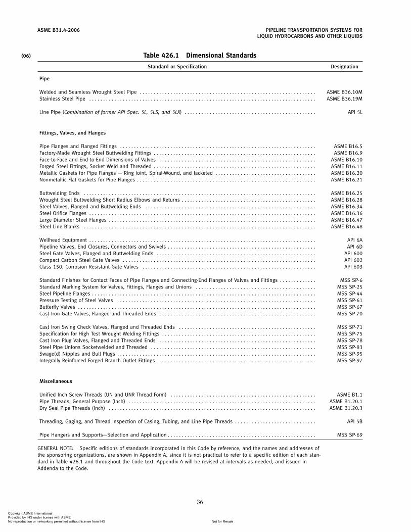
(06)
ASME B31.4-2006 PIPELINE TRANSPORTATION SYSTEMS FORLIQUID HYDROCARBONS AND OTHER LIQUIDS
Table 426.1 Dimensional Standards
Standard or Specification Designation
Pipe
Welded and Seamless Wrought Steel Pipe . . . . . . . . . . . . . . . . . . . . . . . . . . . . . . . . . . . . . . . . . . . . . . . . . . . . . . . . . . . . . . . ASME B36.10MStainless Steel Pipe . . . . . . . . . . . . . . . . . . . . . . . . . . . . . . . . . . . . . . . . . . . . . . . . . . . . . . . . . . . . . . . . . . . . . . . . . . . . . . . . . ASME B36.19M
Line Pipe (Combination of former API Spec. 5L, 5LS, and 5LX) . . . . . . . . . . . . . . . . . . . . . . . . . . . . . . . . . . . . . . . . . . . . . . . API 5L
Fittings, Valves, and Flanges
Pipe Flanges and Flanged Fittings . . . . . . . . . . . . . . . . . . . . . . . . . . . . . . . . . . . . . . . . . . . . . . . . . . . . . . . . . . . . . . . . . . . . . . ASME B16.5Factory-Made Wrought Steel Buttwelding Fittings . . . . . . . . . . . . . . . . . . . . . . . . . . . . . . . . . . . . . . . . . . . . . . . . . . . . . . . . . . ASME B16.9Face-to-Face and End-to-End Dimensions of Valves . . . . . . . . . . . . . . . . . . . . . . . . . . . . . . . . . . . . . . . . . . . . . . . . . . . . . . . . ASME B16.10Forged Steel Fittings, Socket Weld and Threaded . . . . . . . . . . . . . . . . . . . . . . . . . . . . . . . . . . . . . . . . . . . . . . . . . . . . . . . . . . ASME B16.11Metallic Gaskets for Pipe Flanges — Ring Joint, Spiral-Wound, and Jacketed . . . . . . . . . . . . . . . . . . . . . . . . . . . . . . . . . . . . ASME B16.20Nonmetallic Flat Gaskets for Pipe Flanges . . . . . . . . . . . . . . . . . . . . . . . . . . . . . . . . . . . . . . . . . . . . . . . . . . . . . . . . . . . . . . . . ASME B16.21
Buttwelding Ends . . . . . . . . . . . . . . . . . . . . . . . . . . . . . . . . . . . . . . . . . . . . . . . . . . . . . . . . . . . . . . . . . . . . . . . . . . . . . . . . . . . ASME B16.25Wrought Steel Buttwelding Short Radius Elbows and Returns . . . . . . . . . . . . . . . . . . . . . . . . . . . . . . . . . . . . . . . . . . . . . . . . ASME B16.28Steel Valves, Flanged and Buttwelding Ends . . . . . . . . . . . . . . . . . . . . . . . . . . . . . . . . . . . . . . . . . . . . . . . . . . . . . . . . . . . . . ASME B16.34Steel Orifice Flanges . . . . . . . . . . . . . . . . . . . . . . . . . . . . . . . . . . . . . . . . . . . . . . . . . . . . . . . . . . . . . . . . . . . . . . . . . . . . . . . . . ASME B16.36Large Diameter Steel Flanges . . . . . . . . . . . . . . . . . . . . . . . . . . . . . . . . . . . . . . . . . . . . . . . . . . . . . . . . . . . . . . . . . . . . . . . . . . ASME B16.47Steel Line Blanks . . . . . . . . . . . . . . . . . . . . . . . . . . . . . . . . . . . . . . . . . . . . . . . . . . . . . . . . . . . . . . . . . . . . . . . . . . . . . . . . . . . ASME B16.48
Wellhead Equipment . . . . . . . . . . . . . . . . . . . . . . . . . . . . . . . . . . . . . . . . . . . . . . . . . . . . . . . . . . . . . . . . . . . . . . . . . . . . . . . . . API 6APipeline Valves, End Closures, Connectors and Swivels . . . . . . . . . . . . . . . . . . . . . . . . . . . . . . . . . . . . . . . . . . . . . . . . . . . . . API 6DSteel Gate Valves, Flanged and Buttwelding Ends . . . . . . . . . . . . . . . . . . . . . . . . . . . . . . . . . . . . . . . . . . . . . . . . . . . . . . . . . API 600Compact Carbon Steel Gate Valves . . . . . . . . . . . . . . . . . . . . . . . . . . . . . . . . . . . . . . . . . . . . . . . . . . . . . . . . . . . . . . . . . . . . . API 602Class 150, Corrosion Resistant Gate Valves . . . . . . . . . . . . . . . . . . . . . . . . . . . . . . . . . . . . . . . . . . . . . . . . . . . . . . . . . . . . . . API 603
Standard Finishes for Contact Faces of Pipe Flanges and Connecting-End Flanges of Valves and Fittings . . . . . . . . . . . . . MSS SP-6Standard Marking System for Valves, Fittings, Flanges and Unions . . . . . . . . . . . . . . . . . . . . . . . . . . . . . . . . . . . . . . . . . . . MSS SP-25Steel Pipeline Flanges . . . . . . . . . . . . . . . . . . . . . . . . . . . . . . . . . . . . . . . . . . . . . . . . . . . . . . . . . . . . . . . . . . . . . . . . . . . . . . . . MSS SP-44Pressure Testing of Steel Valves . . . . . . . . . . . . . . . . . . . . . . . . . . . . . . . . . . . . . . . . . . . . . . . . . . . . . . . . . . . . . . . . . . . . . . . MSS SP-61Butterfly Valves . . . . . . . . . . . . . . . . . . . . . . . . . . . . . . . . . . . . . . . . . . . . . . . . . . . . . . . . . . . . . . . . . . . . . . . . . . . . . . . . . . . . . MSS SP-67Cast Iron Gate Valves, Flanged and Threaded Ends . . . . . . . . . . . . . . . . . . . . . . . . . . . . . . . . . . . . . . . . . . . . . . . . . . . . . . . . MSS SP-70
Cast Iron Swing Check Valves, Flanged and Threaded Ends . . . . . . . . . . . . . . . . . . . . . . . . . . . . . . . . . . . . . . . . . . . . . . . . . MSS SP-71Specification for High Test Wrought Welding Fittings . . . . . . . . . . . . . . . . . . . . . . . . . . . . . . . . . . . . . . . . . . . . . . . . . . . . . . . MSS SP-75Cast Iron Plug Valves, Flanged and Threaded Ends . . . . . . . . . . . . . . . . . . . . . . . . . . . . . . . . . . . . . . . . . . . . . . . . . . . . . . . . MSS SP-78Steel Pipe Unions Socketwelded and Threaded . . . . . . . . . . . . . . . . . . . . . . . . . . . . . . . . . . . . . . . . . . . . . . . . . . . . . . . . . . . MSS SP-83Swage(d) Nipples and Bull Plugs . . . . . . . . . . . . . . . . . . . . . . . . . . . . . . . . . . . . . . . . . . . . . . . . . . . . . . . . . . . . . . . . . . . . . . . MSS SP-95Integrally Reinforced Forged Branch Outlet Fittings . . . . . . . . . . . . . . . . . . . . . . . . . . . . . . . . . . . . . . . . . . . . . . . . . . . . . . . . MSS SP-97
Miscellaneous
Unified Inch Screw Threads (UN and UNR Thread Form) . . . . . . . . . . . . . . . . . . . . . . . . . . . . . . . . . . . . . . . . . . . . . . . . . . . . ASME B1.1Pipe Threads, General Purpose (Inch) . . . . . . . . . . . . . . . . . . . . . . . . . . . . . . . . . . . . . . . . . . . . . . . . . . . . . . . . . . . . . . . . . . . ASME B1.20.1Dry Seal Pipe Threads (Inch) . . . . . . . . . . . . . . . . . . . . . . . . . . . . . . . . . . . . . . . . . . . . . . . . . . . . . . . . . . . . . . . . . . . . . . . . . . ASME B1.20.3
Threading, Gaging, and Thread Inspection of Casing, Tubing, and Line Pipe Threads . . . . . . . . . . . . . . . . . . . . . . . . . . . . . API 5B
Pipe Hangers and Supports—Selection and Application . . . . . . . . . . . . . . . . . . . . . . . . . . . . . . . . . . . . . . . . . . . . . . . . . . . . . MSS SP-69
GENERAL NOTE: Specific editions of standards incorporated in this Code by reference, and the names and addresses ofthe sponsoring organizations, are shown in Appendix A, since it is not practical to refer to a specific edition of each stan-dard in Table 426.1 and throughout the Code text. Appendix A will be revised at intervals as needed, and issued inAddenda to the Code.
36
Copyright ASME International Provided by IHS under license with ASME
Not for ResaleNo reproduction or networking permitted without license from IHS
--`,,```,,,,````-`-`,,`,,`,`,,`---

(06)
ASME B31.4-2006
Chapter VConstruction, Welding, and Assembly
434 CONSTRUCTION
434.1 General
New construction and replacements of existing sys-tems shall be in accordance with the requirements ofthis Chapter. Where written specifications are required,they shall be in sufficient detail to insure that the require-ments of this Code shall be met. Such specifications shallinclude specific details on handling of pipe, equipment,materials, welding, and all construction factors whichcontribute to safety and sound engineering practice. Itis not intended herein that all construction items becovered in full detail, since the specification should beall-inclusive. Whether covered specifically or not, allconstruction and materials shall be in accordance withgood engineering, safety, and proven pipeline practice.
434.2 Qualifications
434.2.1 Construction Personnel. Construction per-sonnel involved in critical activities shall be qualifiedby either experience or training. Critical activitiesinclude, but are not limited to, the following:
(a) operation of construction equipment;(b) directional drilling equipment operators;(c) individuals responsible for locating underground
structures or utilities;(d) individuals responsible for establishing the loca-
tion of the pilot string during drilling operations; and(e) blasting operations.
434.2.2 Inspection. The operating company shallmake provision for suitable inspection of pipeline andrelated facilities by qualified inspectors to assure compli-ance with the construction specifications. Qualificationof inspection personnel and the type and extent ofinspection shall be in accordance with the requirementsof para. 436. Repairs required during new constructionshall be in accordance with paras. 434.5, 434.8, and461.1.2.
434.3 Right-of-Way
434.3.1 Location. Right-of-way should be selectedso as to minimize the possibility of hazard from futureindustrial or urban development or encroachment onthe right-of-way.
434.3.2 Construction Requirements. Inconvenienceto the landowner should be a minimum and safety ofthe public shall be given prime consideration.
37
(a) All blasting shall be in accordance with governingregulations and shall be performed by competent andqualified personnel, and performed so as to provideadequate protection to the general public, livestock,wildlife, buildings, telephone, telegraph, and powerlines, underground structures, and any other propertyin the proximity of the blasting.
(b) In grading the right-of-way, every effort shall bemade to minimize damage to the land and preventabnormal drainage and erosive conditions. The land is tobe restored to as nearly original condition as is practical.
(c) In constructing pipeline crossings of railroads,highways, streams, lakes, rivers, etc., safety precautionssuch as signs, lights, guard rails, etc., shall be maintainedin the interest of public safety. The crossings shall complywith the applicable rules, regulations, and restrictionsof regulatory bodies having jurisdiction.
434.3.3 Survey and Staking or Marking. The routeshall be surveyed and staked, and such staking or mark-ing should be maintained during construction, exceptroute of pipeline offshore shall be surveyed and thepipeline shall be properly located within theright-of-way by maintaining survey route markers orby surveying during construction.
434.4 Handling, Hauling, Stringing, and Storing
Care shall be exercised in the handling or storing ofpipe, casing, coating materials, valves, fittings, and othermaterials to prevent damage. Transportation by truckor other road vehicles, rail cars, and marine vessels shallbe performed in such a manner as to avoid damage tothe pipe and any pre-applied coatings. Transportationof line pipe shall conform to the requirements of APIRP 5LW and API RP 5L1, as applicable. In the eventpipe is yard coated or mill coated, adequate precautionsshall be taken to prevent damage to the coating whenhauling, lifting, and placing on the right-of-way. Pipeshall not be allowed to drop and strike objects whichwill distort, dent, flatten, gouge, or notch the pipe ordamage the coating, but shall be lifted or lowered bysuitable and safe equipment.
434.5 Damage to Fabricated Items and Pipe
(a) Fabricated items such as scraper traps, manifolds,volume chambers, etc., shall be inspected before assem-bly into the mainline or manifolding and defects shallbe repaired in accordance with provisions of the stan-dard or specification applicable to their manufacture.
(06)
Copyright ASME International Provided by IHS under license with ASME
Not for ResaleNo reproduction or networking permitted without license from IHS
--`,,```,,,,````-`-`,,`,,`,`,,`---

ASME B31.4-2006 PIPELINE TRANSPORTATION SYSTEMS FORLIQUID HYDROCARBONS AND OTHER LIQUIDS
(b) Pipe shall be inspected before coating and beforeassembly into the mainline or manifolding. Distortion,buckling, denting, flattening, gouging, grooves, ornotches, and all defects of this nature, shall be prevented,repaired, or eliminated as specified herein.
(1) Injurious gouges, grooves, or notches shall beremoved. These defects may be repaired by the use ofwelding procedures prescribed in API 5L or removedby grinding, provided the resulting wall thickness is notless than that permitted by the material specification.
(2) When conditions outlined in para. 434.5(b)(1)cannot be met, the damaged portion shall be removedas a cylinder. Insert patching is not permitted. Weld-on patching, other than complete encirclement, is notpermitted in pipelines intended to operate at a hoopstress of more than 20% of the specified minimum yieldstrength of the pipe.
(3) Notches or laminations on pipe ends shall notbe repaired. The damaged end shall be removed as acylinder and the pipe end properly rebeveled.
(4) Distorted or flattened lengths shall be dis-carded.
(5) A dent (as opposed to a scratch, gouge, orgroove) may be defined as a gross disturbance in thecurvature of the pipe wall. A dent containing a stressconcentrator, such as a scratch, gouge, groove, or arcburn, shall be removed by cutting out the damagedportion of the pipe as a cylinder.
(6) All dents which affect the curvature of the pipeat the seam or at any girth weld shall be removed as inpara. 434.5(b)(5). All dents which exceed a maximumdepth of 1⁄4 in. (6 mm) in pipe NPS 4 and smaller, or 6%of the nominal pipe diameter in sizes greater than NPS 4,shall not be permitted in pipelines intended to operate ata hoop stress of more than 20% of the specified minimumyield strength of the pipe. Insert patching, overlay, orpounding out of dents shall not be permitted in pipelinesintended to operate at a hoop stress of more than 20%of the specified minimum yield strength of the pipe.
(7) Buckled pipe shall be replaced as a cylinder.
434.6 Ditching
(a) Depth of ditch shall be appropriate for the routelocation, surface use of the land, terrain features, andloads imposed by roadways and railroads. All buriedpipelines shall be installed below the normal level ofcultivation and with a minimum cover not less than thatshown in Table 434.6(a). Where the cover provisions ofTable 434.6(a) cannot be met, pipe may be installed withless cover if additional protection is provided to with-stand anticipated external loads and to minimize dam-age to the pipe by external forces.
(b) Width and grade of ditch shall provide for low-ering of the pipe into the ditch to minimize damage tothe coating and to facilitate fitting the pipe to the ditch.
38
(c) Location of underground structures intersectingthe ditch route shall be determined in advance of con-struction activities to prevent damage to such structures.A minimum clearance of 12 in. (0.3 m) shall be providedbetween the outside of any buried pipe or componentand the extremity of any other underground structures,except for drainage tile which shall have a minimumclearance of 2 in. (50 mm), and as permitted under para.461.1.1(c).
(d) Ditching operations shall follow good pipelinepractice and consideration of public safety. API RP 1102will provide additional guidance.
434.7 Bends, Miters, and Elbows
Changes in direction, including sags or overbendsrequired to conform to the contour of the ditch, may bemade by bending the pipe or using miters, factory madebends, or elbows. (See limitations in para. 406.2.)
434.7.1 Bends Made From Pipe(a) Bends shall be made from pipe having wall thick-
nesses determined in accordance with para. 404.2.1.When hot bends are made in pipe which has been coldworked in order to meet the specified minimum yieldstrength, wall thicknesses shall be determined by usingthe lower stress values in accordance with para.402.3.1(d).
(b) Bends shall be made in such a manner as to pre-serve the cross-sectional shape of the pipe, and shall befree from buckling, cracks, or other evidence of mechani-cal damage. The pipe diameter shall not be reduced atany point by more than 21⁄2% of the nominal diameter,and the completed bend shall pass the specified siz-ing pig.
(c) The minimum radius of field cold bends shall beas specified in para. 406.2.1(b).
(d) Tangents approximately 6 ft (2 m) in length arepreferred on both ends of cold bends.
(e) When bends are made in longitudinally weldedpipe, the longitudinal weld should be located on or nearthe neutral axis of the bend.
434.7.2 Mitered Bends(a) Mitered bends are permitted subject to limitations
in para. 406.2.2.(b) Care shall be taken in making mitered joints to
provide proper spacing and alignment and full penetra-tion welds.
434.7.3 Factory Made Bends and Elbows(a) Factory made wrought steel welding bends and
factory made elbows may be used subject to limitationsin para. 406.2.3, and transverse segments cut therefrommay be used for changes in direction provided the arcdistance measured along the crotch is at least 2 in.(50 mm) on pipe size NPS 4 and larger.
(b) If the internal diameter of such fittings differs bymore than 3⁄16 in. (5 mm) from that of the pipe, the fitting
(06)
Copyright ASME International Provided by IHS under license with ASME
Not for ResaleNo reproduction or networking permitted without license from IHS
--`,,```,,,,````-`-`,,`,,`,`,,`---

PIPELINE TRANSPORTATION SYSTEMS FOR ASME B31.4-2006LIQUID HYDROCARBONS AND OTHER LIQUIDS
Table 434.6(a) Minimum Cover for Buried Pipelines
For Normal For Rock Excavation RequiringExcavation, Blasting or Removal by
Location in. (m) Equivalent Means, in. (m)
Cultivated, agricultural areas where plowing 48 (1.2) N/Aor subsurface ripping is common [Note (1)]
Industrial, commercial, and residential areas 48 (1.2) 30 (0.75)River and stream crossings 48 (1.2) 18 (0.45)Drainage ditches at roadways and railroads 48 (1.2) 30 (0.75)All other areas 36 (0.9) 18 (0.45)
NOTE:(1) Pipelines may require deeper burial to avoid damage from deep plowing; the designer is cautioned
to account for this possibility.
shall be treated as indicated in Fig. 434.8.6(a)-(2) or usea transition nipple not less than one-half pipe diameterin length with acceptable joint designs as illustrated inFig. 434.8.6(a)-(2).
434.8 Welding
434.8.1 General(a) Scope. Welding herein applies to the arc and gas
welding of pipe in both wrought and cast steel materialsas applied in pipelines and connections to apparatus orequipment. This includes butt joints in the installationof pipe, valves, flanges, fittings, and other equipment,and fillet welded joints in pipe branches, slip-on flanges,etc. It does not apply to the welding of longitudinal orspiral joints in the manufacture of pipe, fittings, andvalves, or to pressure vessels or assemblies manufac-tured in accordance with the ASME Boiler and PressureVessel Code, Section VIII, Division 1 or 2.
(b) Welding Terms. Definitions pertaining to weldingas used in this Code conform to the standard definitionsestablished by the American Welding Society and con-tained in ANSI/AWS A3.0, Section IX of the ASMEBoiler and Pressure Vessel Code, and API 1104.
(c) Safe Practices in Cutting and Welding. Prior to cut-ting and welding in areas in which the possible leakageor presence of vapor or flammable liquid constitutes ahazard of fire or explosion, a thorough check shall bemade to determine the presence of a combustible gasmixture or flammable liquid. Cutting and welding shallbegin only when safe conditions are indicated.
434.8.2 Welding Processes and Filler Metal(a) Welding shall be performed by a manual, semiau-
tomatic, or automatic process or combination of pro-cesses that have been demonstrated to produce soundwelds.
(b) Unless otherwise specified by the operating com-pany, welding electrodes and consumables shall complywith the following:
(1) Filler metal and consumables shall be selectedso that the strength of the completed weldment will
39
equal or exceed the specified minimum tensile strengthof the materials being joined.
(2) If base metals of different tensile strengths areto be joined, the nominal tensile strength of the weldmetal shall equal or exceed the tensile strength of theweaker of the two.
(3) When filler metals of different strenghts areused in a single weld, the proportions shall be such thatthe completed weldment equals the specified minimumtensile strength of the base metal.
(4) For alloy steels, the nominal chemical analysisof the weld metal shall be the same as the nominalchemical analysis of the base metal. If base metals ofdifferent chemical analysis are being joined, the weldmetal shall be the same as eitehr base metal, or of inter-mediate composition, except as specified below.
(5) When austenitic steels are joined to ferriticsteels, the weld metal shall have an austenitic structure.
434.8.3 Welder and Welding Procedure Qualifica-tions
(a) Welder and welding procedure qualifications forcross country pipelines shall be performed in accordancewith API 1104. Welder and welding procedure qualifica-tions for alloy steel and for shop fabricated pipingassemblies, and welding at stations and terminals shallbe performed in accordance with API 1104 or SectionIX of the ASME Boiler and Pressure Vessel Code.
(b) Prior to any welding covered by this Code, a weld-ing procedure specification shal be established and qual-ified by testing to demonstrate that welds havingsuitable mechanical properties and soundness can beproduced. Welding procedure specifications shall bequalified as required by API 1104, or Section IX of theASME Boiler and Pressure Vessel Code, whichever isappropriate for the locations, materials, and type ofwelding to be performed except as modified by the fol-lowing:
(1) Standard Welding Procedures. Standard WeldingProcedure Specifications (SWPSs) published by theAmerican Welding Society and listed in Appendix E of
(06)
(06)
Copyright ASME International Provided by IHS under license with ASME
Not for ResaleNo reproduction or networking permitted without license from IHS
--`,,```,,,,````-`-`,,`,,`,`,,`---

(06)
ASME B31.4-2006 PIPELINE TRANSPORTATION SYSTEMS FORLIQUID HYDROCARBONS AND OTHER LIQUIDS
ASME Section IX are permitted for code constructionwithin the limitations established by Article V of ASMESection IX. The employer shall either demonstrate hisability to follow SWPSs as required by ASME SectionIX or he shall qualify one welder or welding operatorfollowing each SWPS.
(2) Procedure Qualification by Others. In order toavoid duplication of effort and subject to the approvalof the owner, WPSs qualified by a technically competentgroup or agency may be used provided the followingare met:
(1) the WPSs meet the requirements of ASMESection IX or API 1104 and any additional qualificationrequirements of this Code
(2) the employer has qualified at least one welderor welding operator following each WPS
(3) the employer’s business name shall be shownon each WPS and on each qualification record. In addi-tion, qualification records shall be signed and dated bythe employer, thereby accepting responsibility for thequalifications performed by others.
The welding procedure specification shall be adheredto during welding performed under this Code.
(c) The welding procedure specifications shall at aminimum include the information required by API 1104or Section IX of the ASME Boiler and Pressure VesselCode. When materials, welding consumables, mechani-cal restraint, service conditions and/or weather condi-tions make more details necessary to produce a soundweld, such as preheat, interpass temperature, and post-weld heat treatment, such details shall be provided.When joining materials with notch-toughness require-ments, particularly for low temperature service, consid-eration shall be given to weld metal and heat-affectedzone toughness requirements in the welding procedurespecification. When applicable, the test method, temper-ature, specimen, and acceptance criteria shall be speci-fied in the welding procedure specification.
(d) API 1104 and Section IX of the ASME Boiler andPressure Vessel Code contain sections entitled “EssentialVariables” applicable to welding procedure specifica-tions, procedure qualification records, and welder quali-fications. The classification of base materials and weldfiller materials into groups does not imply that othermaterials within a particular group may be indiscrimi-nately substituted for the base material or weld fillermaterial used for the qualificaition test. Welding proce-dure qualification tests should be conducted with thehighest strength base metal to be welded in the essentialvariable groups identified in the procedure specification.
(e) Prior to any welding covered by this Code, eachwelder or welding operator shall be qualified as requiredby API 1104, or Section IX of the ASME Boiler andPressure Vessel Code, whichever is appropriate for thelocations, materials, and type of welding to be per-formed.
40
In order to avoid duplication of effort and subject tothe approval of the owner, an employer may acceptthe performance qualification of a welder or weldingoperator made by a previous employer. This acceptanceis limited to performance qualifications that were madeon pipe or tube test coupons. The new employer shallhave the WPS that was followed during qualification oran equivalent WPS that is within the limits of the essen-tial variables. An employer accepting such qualificationtests shall obtain a copy of the performance qualificationtest record from the previous employer. The record shallshow the name of the employer by whom the weldersor welding operator was qualified and the date of thatqualification. A record showing use of the process orprocesses from the date of the welder’s qualificationshall be available. The new employer’s business nameshall be shown on the qualification record, and it shallbe signed and dated by the employer thereby acceptingresponsibility for the qualifications performed by others.
Welder requalification tests are required if there issome specific reason to question a welder’s ability or ifthe welder is not engaged in a given process of weldingfor a period of six months or more.
(f) The operating company shall be responsible forqualifications of procedures and welders. The prepara-tion of welding procedure specifications and/or per-formance of welding qualification tests may bedelegated to others; however, each company that per-forms welding activities is responsible for the weldingactivities performed by its employees and contractors.
(g) Qualification Records. The welding procedure fol-lowed during the qualifying tests shall be recorded indetail. Records of the tests that establish the qualificationof a welding procedure specification shall be retained aslong as that procedure is in use. A record of the weldersqualified, showing the date and results of the tests, shallbe retained during the construction involved and for sixmonths thereafter. These records shall be available to theowner or the owner’s agent and the inspector at the loca-tion where the welding is being done.
434.8.4 Welding Standards. All the welding doneunder this Code shall be performed under a specificationwhich embodies the minimum requirements of thisCode and shall encompass the requirements of API 1104except as provided in paras. 434.8.3(a) and (b).
434.8.5 Required Inspection and Acceptance Criteria(a) Required Inspection
(1) The quality of welding shall be checked byvisual inspection and supplemental nondestructivemethods or by removing completed welds as selectedand designated by the inspector for destructive testing.
(2) All welds shall be visually inspected.(3) When the pipeline is to be operated at a hoop
stress of more than 20% of the specified minimum yieldstrength of the pipe, the welds shall be inspected. Aminimum of 10% of the girth welds and 10% of the other
(06)
(06)
Copyright ASME International Provided by IHS under license with ASME
Not for ResaleNo reproduction or networking permitted without license from IHS
--`,,```,,,,````-`-`,,`,,`,`,,`---

PIPELINE TRANSPORTATION SYSTEMS FOR ASME B31.4-2006LIQUID HYDROCARBONS AND OTHER LIQUIDS
welds completed each day shall be randomly selected bythe operating company and nondestructively inspected.The inspection of girth welds shall be by radiographicor other accepted volumetric methods. Nonvolumetricmethods, such as dye penetrant or magnetic particle,may be used for other welds. Each weld inspected shallbe inspected completely with the selected method. Inthe following locations or conditions, all welds in thepipe shall be completely inspected; however, if some ofthe welds are inaccessible, a minimum of 90% of thewelds are to be inspected:
(a) within populated areas such as residentialsubdivisions, shopping centers, and designated com-mercial and industrial areas
(b) river, lake, and stream crossings within thearea subject to frequent inundation; and river, lake, andstream crossings on bridges
(c) railroad or public highway rights-of-way,including tunnels, bridges, and overhead railroad androad crossings
(d) offshore and inland coastal waters(e) old girth welds in used pipe(f) tie-in girth welds not hydrostatically tested
in accordance with para. 437.4.1(b) Inspection Methods and Acceptance Standards
(1) Nondestructive inspection shall consist ofvisual inspection and radiographic examination or otheracceptable nondestructive methods, and shall be inaccordance with API 1104. The methods used shall becapable of producing indications of potential defectsthat can be accurately interpreted and evaluated. Weldsshall meet the acceptance standards for discontinuitiescontained in API 1104, or the alternate acceptance stan-dards for girth welds in Appendix A of API 1104.
(2) Completed welds which have been removed fordestructive examination shall meet the requirements ofAPI 1104 for Welder Qualification by Destructive Test-ing. Trepanning methods of testing shall not be used.
434.8.6 Types of Welds, Joint Designs, and TransitionNipples
(a) Butt Welds. Butt welded joints may be of the singlevee, double vee, or other suitable type of groove. Jointdesigns shown in Fig. 434.8.6(a)-(1) or applicable combi-nations of these joint design details are recommendedfor ends of equal thickness. The transition between endsof unequal thickness may be accomplished by taper orwelding as shown in Fig. 434.8.6(a)-(2), or by means ofa prefabricated transition nipple not less than one-halfpipe diameter in length with acceptable joint designs asillustrated in Fig. 434.8.6(a)-(2).
(b) Fillet Welds. Fillet welds may be concave toslightly convex. The size of a fillet weld is stated as aleg length of the largest inscribed right isosceles triangleas shown in Fig. 434.8.6(b) covering recommendedattachment details of flanges.
41
(c) Tack Welds. Tack welding shall be done by quali-fied welders, the same as all other welds.
434.8.7 Removal or Repair of Defects(a) Arc Burns. Arc burns can cause serious stress con-
centrations in pipelines and shall be prevented,removed, or repaired. The metallurgical notch causedby arc burns shall be removed by grinding, provided thegrinding does not reduce the remaining wall thicknessto less than the minimum permitted by the materialspecifications. Complete removal of the metallurgicalnotch created by an arc burn can be determined as fol-lows. After visible evidence of the arc burn has beenremoved by grinding, swab the ground area with a mini-mum 10% solution of ammonium persulfate or a 5%solution of nital. A darkened spot is evidence of a metal-lurgical notch and indicates that additional grinding isnecessary. If the resulting wall thickness after grindingis less than that permitted by the material specification,the portion of pipe containing the arc burn shall beremoved or repaired in accordance with para. 451.6.Insert patching is prohibited.
(b) Weld Defects. Authorization for repair of welds,removal and repair of weld defects, and testing of weldrepairs shall be in accordance with API 1104.
(c) Pipe Defects. Laminations, split ends, or otherdefects in the pipe shall be repaired or removed in accor-dance with para. 434.5(b).
434.8.8 Preheating and Interpass Temperature(a) The welding procedure specification shall specify
the minimum preheat temperature. When the weldingprocedure specification specifies preheating aboveambient temperatures, the method of heating shall bespecified. For heat treated and other high strength mate-rials and impact tested materials, control of interpasstemperatures may be necessary. The operating companyshall determine when interpass temperature limits arenecessary, and, when required, the interpass tempera-tures shall be provided in the welding procedure specifi-cation.
(b) When welding dissimilar materials having differ-ent preheating requirements, the material requiring thehigher preheat shall govern.
(c) The preheating temperature shall be checked bythe use of temperature indicating crayons, thermocouplepyrometers, or other suitable method to assure that therequired temperature is attained prior to and maintainedduring the welding operation.
434.8.9 Stress Relieving(a) Welds shall be stress relieved when the effective
weld throat [see Fig. 434.8.6(a)-(2)] exceeds 11⁄4 in.(32 mm), unless it can be demonstrated by welding pro-cedure qualification tests, using materials of the samespecification, type, and grade with an effective weldthroat that is equal to or greater than the productionweld, that stress relieving is not necessary.
Copyright ASME International Provided by IHS under license with ASME
Not for ResaleNo reproduction or networking permitted without license from IHS
--`,,```,,,,````-`-`,,`,,`,`,,`---

ASME B31.4-2006 PIPELINE TRANSPORTATION SYSTEMS FORLIQUID HYDROCARBONS AND OTHER LIQUIDS
Fig. 434.8.6(a)-(1) Acceptable Butt Welded Joint Design for Equal Wall Thicknesses
42
Copyright ASME International Provided by IHS under license with ASME
Not for ResaleNo reproduction or networking permitted without license from IHS
--`,,```,,,,````-`-`,,`,,`,`,,`---
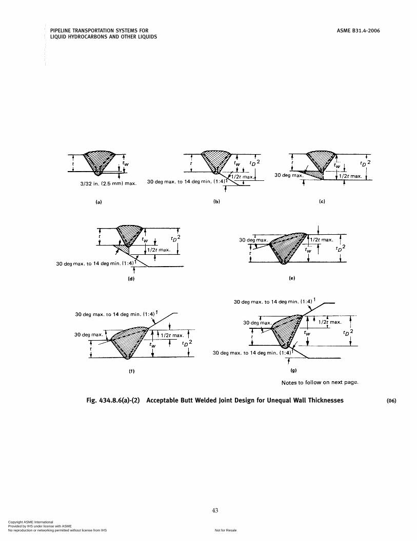
PIPELINE TRANSPORTATION SYSTEMS FOR ASME B31.4-2006LIQUID HYDROCARBONS AND OTHER LIQUIDS
Fig. 434.8.6(a)-(2) Acceptable Butt Welded Joint Design for Unequal Wall Thicknesses
43
(06)
Copyright ASME International Provided by IHS under license with ASME
Not for ResaleNo reproduction or networking permitted without license from IHS
--`,,```,,,,````-`-`,,`,,`,`,,`---

ASME B31.4-2006 PIPELINE TRANSPORTATION SYSTEMS FORLIQUID HYDROCARBONS AND OTHER LIQUIDS
NOTES:(1) No minimum when materials joined have equal yield strength [see General Note (f)].(2) Maximum thickness tD for design purposes shall not be greater than 1.5t.
GENERAL NOTES:(a) The sketches in Fig. 434.8.6(a)-(2) illustrate acceptable preparations for joining pipe ends having unequal wall
thicknesses and/or materials of unequal specified minimum yield strength by butt welding.(b) The wall thickness of the pipes to be joined, beyond the joint design area, shall comply with the design requirements
of this Code.(c) When the specified minimum yield strengths of the pipes to be joined are unequal, the deposited weld metal shall
have mechanical properties at least equal to those of the pipe having the higher strength.(d) The transition between ends of unequal thickness may be accomplished by taper or welding as illustrated or by means
of a prefabricated transition nipple not less than one-half pipe diameter in length.(e) Sharp notches or grooves at the edge of the weld where it joins a slanted surface shall be avoided.(f) For joining pipes of unequal wall thicknesses and equal specified minimum yield strengths, the rules given herein
apply, except there is no minimum angle limit to the taper.(g) The effective weld throat tW shall be used for determining postweld heat treatment requirements.
INTERNAL DIAMETERS UNEQUAL:(1) If the nominal wall thicknesses of the adjoining pipe ends do not vary more than 3⁄32 in. (2.5 mm), no special
treatment is necessary provided full penetration and bond is accomplished in welding. See sketch (a).(2) Where the nominal internal offset is more than 3⁄32 in. (2.5 mm) and there is no access to the inside of the pipe for
welding, the transition shall be made by a taper cut on the inside end of the thicker pipe. See sketch (b). The taperangle shall not be steeper than 30 deg nor less that 14 deg.
(3) For hoop stresses of more than 20% of the specified minimum yield strength of the pipe, where the nominal internaloffset is more than 3⁄32 in. (2.5 mm), but does not exceed one-half the wall thickness of the thinner pipe, and there isaccess to the inside of the pipe for welding, the transition may be made wih a tapered weld. See sketch (c). The landon the thicker pipe shall be equal to the offset plus the land on abutting pipe.
(4) Where the nominal internal offset is more than one-half the wall thickness of the thinner pipe, and there is access tothe inside of the pipe for welding, the transition may be made with a taper cut on the inside end of the thicker pipe[see sketch (b)], or by a combination taper weld to one-half the wall thickness of the thinner pipe and a taper cut fromthat point [see sketch (d)].
EXTERNAL DIAMETERS UNEQUAL:(5) Where the external offset does not exceed one-half the wall thickness of the thinner pipe, the transition may be made
by welding [see sketch (e)], provided the angle of rise of the weld surface does not exceed 30 deg and both beveledges are properly fused.
(6) Where there is an external offset exceeding one-half the wall thickness of the thinner pipe, that portion of the offsetover one-half the wall thickness of the thinner pipe shall be tapered. See sketch (f).
INTERNAL AND EXTERNAL DIAMETERS UNEQUAL:(7) Where there is both an internal and an external offset, the joint design shall be a combination of sketches (a) to (f).
See sketch (g). Particular attention shall be paid to proper alignment under these conditions.
Fig. 434.8.6(a)-(2) Acceptable Butt Welded Joint Design for Unequal Wall Thicknesses (Cont’d)(06)
44
Copyright ASME International Provided by IHS under license with ASME
Not for ResaleNo reproduction or networking permitted without license from IHS
--`,,```,,,,````-`-`,,`,,`,`,,`---

PIPELINE TRANSPORTATION SYSTEMS FOR ASME B31.4-2006LIQUID HYDROCARBONS AND OTHER LIQUIDS
Fig. 434.8.6(b) Recommended Attachment Details of Flanges
45
Copyright ASME International Provided by IHS under license with ASME
Not for ResaleNo reproduction or networking permitted without license from IHS
--`,,```,,,,````-`-`,,`,,`,`,,`---

ASME B31.4-2006 PIPELINE TRANSPORTATION SYSTEMS FORLIQUID HYDROCARBONS AND OTHER LIQUIDS
Welds in carbon steels having an effective weld throatlarger than 11⁄4 in. (32 mm) and not larger than 11⁄2 in.(38 mm) may be exempted from stress relieving if aminimum preheating temperature of 200°F (93°C) isused. The welding procedure specification shall specifywhen stress relieving and/or heat treatment are requireddue to composition, thickness, welding process, restraintof the weld joint, or service conditions. When required,the welding procedure qualification test shall includestress relieving and/or heat treatment of the completedtest joint. The postweld stress relieving and heat treat-ment requirements in ASME B31.3 or Section VIII, Divi-sion 1 or 2 of the ASME Boiler and Pressure Vessel Codemay be used as a guide for minimum stress relievingand heat treating requirements. The thickness to be usedto determine the stress relieving requirements of branchconnections or slip-on flanges shall be the thickness ofthe pipe or header.
The thickness to be used to determine the stress reliev-ing requirements of branch connections or slip-onflanges shall be the thickness of the pipe or header.
(b) In welds between dissimilar materials, if eithermaterial requires stress relieving, the joint shall requirestress relieving.
434.9 Tie-In
Gaps left in the continuous line construction at suchpoints as river, canal, highway, or railroad crossingsrequire special consideration for alignment and welding.Sufficient equipment shall be available and care exer-cised not to force or strain the pipe to proper alignment.
434.10 Installation of Pipe in the Ditch
It is very important that stresses induced into thepipeline by construction be minimized. The pipe shallfit the ditch without the use of external force to hold itin place until the backfill is completed. When the pipeis lowered into the ditch, care shall be exercised so asnot to impose undue stress in the pipe. Slack loops maybe used where laying conditions render their useadvisable.
434.11 Backfilling
Backfilling shall be performed in a manner to providefirm support of the pipe. When there are large rocks inthe backfill material, care shall be exercised to preventdamage to the pipe and coating by such means as theuse of a rock shield material, or by making the initialfill with a rock-free material sufficient to prevent rockdamage. Where the ditch is flooded, care shall be exer-cised so that the pipe is not floated from the bottom ofthe ditch prior to backfill completion.
434.12 Restoration of Right-of-Way and Cleanup
These operations shall follow good construction prac-tices and considerations of private and public safety.
46
434.13 Special Crossings
Water, railroad, and highway crossings require spe-cific considerations not readily covered in a generalstatement, since all involve variations in basic design.The pipeline company shall obtain required permits forsuch crossings. The design shall employ sound engi-neering and good pipeline practice with minimum haz-ard to the facility and due consideration of public safety.Construction shall be so organized as to result in mini-mal interference with traffic or the activities of adjacentproperty owners. Adequate efforts shall be made todetermine the location of buried pipelines, utility lines,and other underground structures along and crossingthe proposed right-of-way. The owners of any affectedstructures shall be given adequate prior notice of theproposed construction so that the owner may makeoperational preparations and provide a representativeat the crossing.
434.13.1 Water Crossings. Crossings of rivers,streams, lakes, and inland bodies of water are individualproblems, and the designer shall investigate composi-tion of bottom, variation in banks, velocity of water,scouring, and special seasonal problems. The designershall determine whether the crossing is to be underwa-ter, overhead on a suspension bridge, or supported onan adjacent bridge. Continuity of operation and thesafety of the general public shall be the controlling fac-tors both in design and in construction. Where required,detailed plans and specifications shall be prepared tak-ing into account these and any special considerationsor limitations imposed by the regulatory body involved.
(a) Underwater Construction. Plans and specificationsshall describe the position of the line, showing relation-ship of the pipeline to the natural bottom and the depthbelow mean low water level when applicable. To meetthe conditions set out in para. 434.13.1, heavier wall pipemay be specified. Approach and position of the line inthe banks is important, as is the position of the lineacross the bottom. Special consideration shall be givento depth of cover and other means of protecting thepipeline in the surf zone. Special consideration shallbe given to protective coating and the use of concretejacketing or the application of river weights. Completeinspection shall be provided. Precautions shall be takenduring construction to limit stress below the level thatwould produce buckling or collapse due to out-of-roundness of the completed pipeline.
434.13.2 Overhead Structures. Overhead structuresused to suspend pipelines shall be designed and con-structed on the basis of sound engineering and withinthe restrictions or regulations of the governing bodyhaving jurisdiction. Detailed plans and specificationsshall be prepared where required and adequate inspec-tion shall be provided to assure complete adherencethereto.
Copyright ASME International Provided by IHS under license with ASME
Not for ResaleNo reproduction or networking permitted without license from IHS
--`,,```,,,,````-`-`,,`,,`,`,,`---

(06)
PIPELINE TRANSPORTATION SYSTEMS FOR ASME B31.4-2006LIQUID HYDROCARBONS AND OTHER LIQUIDS
434.13.3 Bridge Attachments. Special requirementsare involved in this type of crossing. The use of higherstrength lightweight steel pipe, proper design and instal-lation of hangers, and special protection to prevent dam-age by the elements or bridge and approach traffic shallbe considered. Any agreed upon restrictions or precau-tions shall be contained in the detailed specifications.Inspectors shall assure themselves that these require-ments are met.
434.13.4 Railroad and Highway Crossings(a) The safety of the general public and the prevention
of damage to the pipeline by reason of its location areprimary considerations. The great variety of such cross-ings precludes standard design. The construction speci-fications shall cover the procedure for such crossings,based upon the requirements of the specific location.
(b) Installation of uncased carrier pipe is preferred.Installation of carrier pipe, or casing if used, shall bein accordance with API RP 1102. As specified in para.461.1.2(f), if casing is used, coated carrier pipe shall beindependently supported outside each end of the casingand insulated from the casing throughout the cased sec-tion, and casing ends shall be sealed using a durable,electrically nonconductive material.
(c) The total effective stress due to internal designpressure and external loads (including both live anddead loads) in pipe installed under railroads or high-ways without use of casing shall be calculated in accor-dance with API RP 1102 and shall not exceed theallowable effective stress noted in para. 402.3.2(e). Also,cyclic stress components shall be checked for fatigue.
434.13.5 Directionally Drilled Crossings. Writtenplans shall be developed for all directionally drilledcrossings or for when directional drilling is selected asa pipe lay method. Plans will include the following:
(a) crossing plan and profile drawings showing allpipelines, utilities, cables, and structures that cross thedrill path, are parallel to and within 100 ft (30 m) of thedrill path, and that are within 100 ft (30 m) of the drillingoperation, including mud pits and bore pits.
(b) a Damage Prevention Plan to reduce the likelihoodof damage to adjacent underground facilites, includingpipelines, utilities, cables, and other subsurface struc-tures. The Plan shall consider the accuracy of the methodto be employed in locating existing structures and intracking the position of the pilot string during drilling.Consideration should be given to having an auxiliarylocation system to include manual excavation to ensurethat the drilling bit or reamer is following the projectedpath and does not encroach upon crossing or parallellines. The Damage Prevention Plan should provide spe-cific instructions regarding the notification of affectedparties including the participation in One-Call systemswhere applicable.
47
(c) a written Safety Plan to include contingency plansin the event the drilling string impacts subsurface facili-ties. The Safety Plan should identify facilities andresources to be utilized in the event of an emergency orany personnel injuries. The Safety Plan shall be reviewedon site with all construction personnel prior to the com-mencement of drilling operations.
(d) plan for containment and disposal of drilling flu-ids, if used.
(e) hydrostatic test plan that should consider pre-testing of the fabricated string(s) prior to installing thecrossing.
The following publications provide guidance ondesign of directionally drilled crossings:
(1) American Gas Association PR-227-9424 “Instal-lation of Pipelines by Horizontal Directional Drilling,An Engineering Design Guide”
(2) American Society of Civil Engineering, PracticeNo. 89 — “Pipeline Crossings Handbook”
(3) Directional Crossing Contractors Associationpublications “Guidelines For A Successful DirectionalCrossing Bid Package”, “Directional Crossing SurveyStandards”, and “Guidelines for Successful Mid-SizedDirectional Drilling Projects”
434.14 Inland Coastal Water Construction
Plans and specifications shall describe alignment ofthe pipeline, depth below mean water level, and depthbelow bottom if ditched. Special consideration shall begiven to depth of cover and other means of protectingthe pipeline in the surf zone. Consideration shall begiven to use of weight coating(s), anchors, or othermeans of maintaining position of the pipe under antici-pated conditions of buoyance and water motion. Com-plete construction inspection shall be provided.Precautions shall be taken during construction to limitstress below the level that would produce buckling orcollapse due to out-of-roundness of the completedpipeline.
434.15 Block and Isolating Valves
434.15.1 General(a) Block and isolating valves shall be installed for
limiting hazard and damage from accidental dischargeand for facilitating maintenance of the piping system.
(b) Valves shall be at accessible locations, protectedfrom damage or tampering, and suitably supported toprevent differential settlement or movement of theattached piping. Where an operating device to open orclose the valve is provided, it shall be protected andaccessible only to authorized persons.
(c) Submerged valves on pipelines shall be marked orspotted by survey techniques to facilitate quick locationwhen operation is required.
Copyright ASME International Provided by IHS under license with ASME
Not for ResaleNo reproduction or networking permitted without license from IHS
--`,,```,,,,````-`-`,,`,,`,`,,`---

ASME B31.4-2006 PIPELINE TRANSPORTATION SYSTEMS FORLIQUID HYDROCARBONS AND OTHER LIQUIDS
434.15.2 Mainline Valves(a) Mainline block valves shall be installed on the
upstream side of major river crossings and public watersupply reservoirs. Either a block or check valve shall beinstalled on the downstream side of major river cross-ings and public water supply reservoirs.
(b) A mainline block valve shall be installed at main-line pump stations, and a block or check valve (whereapplicable to minimize pipeline backflow) shall beinstalled at other locations appropriate for the terrainfeatures. In industrial, commercial, and residential areaswhere construction activities pose a particular risk ofexternal damage to the pipeline, provisions shall bemade for the appropriate spacing and location of main-line valves consistent with the type of liquids beingtransported.
(c) A remotely operated mainline block valve shallbe provided at remotely controlled pipeline facilities toisolate segments of the pipeline.
(d) On piping systems transporting LPG or liquidanhydrous ammonia, check valves shall be installedwhere applicable with each block valve to provide auto-matic blockage of reverse flow in the piping system.
(e) In order to facilitate operational control, limit theduration of an outage, and to expedite repairs, mainlineblock valves shall be installed at 7.5 mile (12 km) maxi-mum spacing on piping systems transporting LPG orliquid anhydrous ammonia in industrial, commercial,and residential areas.
434.15.3 Pump Station, Tank Farm, and TerminalValves
(a) Valves shall be installed on the suction and dis-charge of pump stations whereby the pump station canbe isolated from the pipeline.
(b) Valves shall be installed on lines entering or leav-ing tank farms or terminals at convenient locationswhereby the tank farm or terminal may be isolated fromother facilities such as the pipeline, manifolds, or pumpstations.
434.16 Connections to Main Lines
Where connections to the main line such as branchlines, jump-overs, relief valves, air vents, etc., are madeto the main line, they shall be made in accordance withpara. 404.3.1. When such connections or additions aremade to coated lines, all damaged coating shall beremoved and replaced with new coating material inaccordance with para. 461.1.2(h). This protective coatingshould include the attachments.
434.17 Scraper Traps
434.17.1 Scraper traps are to be installed asdeemed necessary for good operations. All pipe, valves,fittings, closures, and appurtenances shall comply withappropriate sections of this Code.
48
434.17.2 Scraper traps on mainline terminationsand tied into connection piping or manifolding shall beanchored below ground with adequate concrete anchorswhen required and suitably supported above ground toprevent transmission of line stresses due to expansionand contraction to connecting facilities.
434.17.3 Scraper trap and its components shall beassembled in accordance with para. 435, and pressuretested to the same limits as the main line. See para. 437.4.
434.17.4 All in-line mainline pipeline scraper trapsshall accommodate the passage of instrumented internalinspectin devices during launching and receiving opera-tions.
434.18 Line Markers
(a) Except as provided in paragraph (d) of this section,adequate pipeline location markers for the protectionof the pipeline, the public, and persons performing workin the area shall be placed over each buried pipeline inaccordance with the following:
(1) Markers shall be located at each public roadcrossing, at each railroad crossing, at each navigablestream crossing, and in sufficient numbers along theremainder of the buried line so that the pipeline locationincluding direction of the pipeline is adequately known.It is recommended that markers are installed on eachside of each crossing whenever possible.
(2) Markers shall be installed at locations wherethe line is above ground in areas which are accessibleto the public.
(b) The marker shall state at least the following on abackground of sharply contrasting colors:
(1) The word “Warning,” “Caution,” or “Danger”followed by the words “Petroleum (or the name of thehazardous liquid transported) Pipeline” or “CarbonDioxide Pipeline” all of which, except for markers inheavily developed urban areas, must be in letters atleast one inch high with an approximate stroke of one-quarter inch.
(2) The name of the operator and a telephone num-ber (including area code) where the operator can bereached at all times.
(c) API RP 1109 should be used for additionalguidance.
(d) Unless required by applicable regulatory agencies,line markers are not required for buried pipelineslocated offshore or under waterways and other bodiesof water, or in heavily developed urban areas such asdowntown business centers where the placement ofmarkers is impractical and would not serve the purposefor which markers are intended and the local govern-ment maintains substructure records.
(06)
Copyright ASME International Provided by IHS under license with ASME
Not for ResaleNo reproduction or networking permitted without license from IHS
--`,,```,,,,````-`-`,,`,,`,`,,`---

PIPELINE TRANSPORTATION SYSTEMS FOR ASME B31.4-2006LIQUID HYDROCARBONS AND OTHER LIQUIDS
434.19 Corrosion Control
Protection of ferrous pipe and components from exter-nal and internal corrosion shall be as prescribed in Chap-ter VIII.
434.20 Pump Station, Tank Farm, and TerminalConstruction
434.20.1 General. All construction work performedon pump stations, tank farms, terminals, equipmentinstallations, piping, and allied facilities shall be doneunder construction specifications. Such specificationsshall cover all phases of the work under contract andshall be in sufficient detail to insure that the require-ments of this Code shall be met. Such specifications shallinclude specific details on soil conditions, foundationsand concrete work, steel fabrication and building erec-tion, piping, welding, equipment and materials, and allconstruction factors contributing to safety and soundengineering practice.
434.20.2 Location. Pump stations, tank farms, andterminals should be located on the pipeline’s fee orleased property in order to be assured that proper safetyprecautions may be applied. The pump station, tankfarm, or terminal shall be located at such clear distancesfrom adjacent properties not under control of the com-pany as to minimize the communication of fire fromstructures on adjacent properties. Similar considerationshall be given to its relative location from the stationmanifolds, tankage, maintenance facilities, personnelhousing, etc. Sufficient open space shall be left aroundthe building and manifolds to provide access for mainte-nance equipment and fire fighting equipment. The sta-tion, tank farm, or terminal shall be fenced in such amanner as to minimize trespass, and roadways and gatesshould be located to give ready access to or egress fromthe facilities.
434.20.3 Building Installation. Buildings shall belocated and constructed to comply with detailed plansand specifications. The excavation for and installationof foundations and erection of the building shall be doneby craftsmen familiar with the respective phase of thework, and all work shall be done in a safe and workman-like manner. Inspection shall be provided to assure thatthe requirements of the plans and specifications are met.
434.20.4 Pumping Equipment and Prime Movers.Installation of pumping equipment and prime moversshall be covered by detailed plans and specificationswhich have taken into account the variables inherent inlocal soil conditions, utilization, and arrangement of theequipment to provide the optimum in operating easeand maintenance access. Machinery shall be handledand mounted in accordance with recognized good mill-wright practice and be provided with such protective
49
covers as to prevent damage during construction. Rec-ommendations of installation details provided by manu-facturers for auxiliary piping, setting, and aligning shallbe considered as minimum requirements.
434.20.5 Pump Station, Tank Farm, and Terminal Pip-ing. All piping, including but not limited to main unitinterconnections, manifolds, scraper traps, etc., whichcan be subject to the mainline pressure shall be con-structed in accordance with the welding standards (seepara. 434.8), corrosion control requirements (see ChapterVIII), and other practices of this Code.
434.20.6 Controls and Protective Equipment. Pres-sure controls and protective equipment, including pres-sure limiting devices, regulators, controllers, reliefvalves, and other safety devices, as shown on the draw-ings or required by the specifications, shall be installedby competent and skilled workmen. Installation shallbe accomplished with careful handling and minimumexposure of instruments and devices to inclementweather conditions, dust, or dirt to prevent damage.Also, piping, conduits, or mounting brackets shall notcause the instruments or devices to be distorted or inany strain. Instruments and devices shall be installed sothat they can be checked without undue interruptionsin operations. After installation, controls and protectiveequipment shall be tested under conditions approximat-ing actual operations to assure their proper functioning.
434.20.7 Fire Protection. Fire protection when pro-vided shall be in accordance with recommendations inNFPA 30. If the system installed requires the servicesof fire pumps, their motive power shall be separate fromthe station power so that their operation shall not beaffected by emergency shutdown facilities.
434.21 Storage and Working Tankage
434.21.1 General. All construction work performedon storage and working tankage and allied equipment,piping, and facilities shall be done under constructionspecifications. Such specifications shall cover all phasesof the work under contract, and shall be in sufficientdetail to insure that the requirements of the Code shallbe met. Such specifications shall include specific detailson soil conditions, foundations and concrete work, tankfabrication and erection, piping, welding, equipmentand materials, dikes, and all construction factors contrib-uting to safety and sound engineering practice.
434.21.2 Location(a) Tankage shall be located on the pipeline’s fee or
leased property in order to assure that proper safetyprecautions may be applied. Tank facilities shall belocated at such clear distances from adjacent propertiesnot under control of the company as to minimize thecommunication of fire from structures on adjacent prop-erties. Similar consideration shall be given to relative
Copyright ASME International Provided by IHS under license with ASME
Not for ResaleNo reproduction or networking permitted without license from IHS
--`,,```,,,,````-`-`,,`,,`,`,,`---
ASME B31.4-2006 PIPELINE TRANSPORTATION SYSTEMS FORLIQUID HYDROCARBONS AND OTHER LIQUIDS
locations between station manifolds, pumping equip-ment, maintenance facilities, personnel housing, etc. Suf-ficient open space shall be left around the tankagefacilities and associated equipment to provide access formaintenance and fire fighting equipment. The tankagearea shall be fenced so as to minimize trespass, androadways and gates should be located to give readyingress to and egress from the facilities.
(b) Spacing of tankage shall be governed by therequirements of NFPA 30.
434.21.3 Tanks and Pipe-Type Storage(a) Tanks for storage or handling crude oil and liquid
petroleum products and liquid alcohols having vaporpressures approximating atmospheric shall be con-structed in accordance with API 650, API 12B, API 12D,API 12F, or designed and constructed in accordance withaccepted good engineering practices.
(b) Tanks for storage or handling liquid petroleumproducts and liquid alcohols having vapor gage pres-sures of 0.5 psi (0.035 bar) but not exceeding 15 psi(1 bar) shall be constructed in accordance with API 620.
(c) Tanks used for storage or handling liquids havingvapor gage pressures greater than 15 psi (1 bar) shallbe designed and constructed in accordance with thedesign of accredited tank builders and the ASME Boilerand Pressure Vessel Code, Section VIII, Division 1 orDivision 2.
(d) Buried pipe-type holders used for storage andhandling liquid petroleum, liquid alcohols, or liquidanhydrous ammonia shall be designed and constructedin accordance with the requirements of this Code forpipe and piping components.
434.21.4 Foundations. Tank foundations shall beconstructed in accordance with plans and specificationswhich shall take into account local soil conditions, typeof tank, usage, and general location.
434.21.5 Dikes or Firewalls. The protection of thepipeline’s station, tank farm, terminal, or other facilitiesfrom damage by fire from adjacent facilities, as well asthe protection of the general public, may dictate theneed of dikes or firewalls around tankage or betweentankage and station or terminal. Tank dikes or firewalls,where required, shall be constructed to meet the capacityrequirements set out in NFPA 30.
434.22 Electrical Installations
434.22.1 General. Electrical installations for light-ing, power, and control shall be covered by detailedplans and specifications, and installations shall be inaccordance with codes applicable to the specific type ofcircuitry and classification of areas for electrical installa-tion. Inspection shall be provided and all circuitry shallbe tested before operation to assure that the installationwas made in workmanlike manner to provide for the
50
continuing safety of personnel and equipment. Installa-tions shall be made in accordance with NFPA 70 andAPI RP 500C.
434.22.2 Care and Handling of Materials. All electri-cal equipment and instruments shall be carefully han-dled and properly stored or enclosed to prevent damage,deterioration, or contamination during construction.Packaged components are not to be exposed until instal-lation. Equipment susceptible to damage or deteriora-tion by exposure to humidity shall be adequatelyprotected by using appropriate means such as plasticfilm enclosures, desiccants, or electric heating.
434.22.3 Installation. The installation of electricalmaterials shall be made by qualified personnel familiarwith details of electrical aspects and code requirementsfor such installation. At all times care shall be exercisedto prevent damage to the insulation of cable and wiring.All partial installations shall be protected from damageduring construction. The installation design and specifi-cations shall give consideration to the need for dust-and/or moisture-proof enclosures for such special gearas relays, small switches, and electronic components.In no case shall the frames of electric motors or othergrounded electrical equipment be used as the groundconnection for electrical welding.
434.23 Liquid Metering
434.23.1 Positive displacement meters, turbinemeters, or equivalent liquid measuring devices and theirproving facilities shall be designed and installed inaccordance with the API Manual of Petroleum Measure-ment Standards.
434.23.2 Provisions shall be made to permit accessto these facilities by authorized personnel only.
434.23.3 Assembly of the metering facility compo-nents shall be in accordance with para. 435.
434.24 Liquid Strainers and Filters
434.24.1 Strainers and filters shall be designed tothe same pressure limitations and subjected to the sametest pressures as the piping system in which they areinstalled, and supported in such a manner as to preventundue loading to the connecting piping system.
434.24.2 Installation and design shall provide forease of maintenance and servicing without interferencewith the station operation.
434.24.3 The filtering medium should be of suchretention size and capacity as to fully protect the facilitiesagainst the intrusion of harmful foreign substances.
434.24.4 Assembly of strainers or filters and theircomponents shall be in accordance with para. 435.
Copyright ASME International Provided by IHS under license with ASME
Not for ResaleNo reproduction or networking permitted without license from IHS
--`,,```,,,,````-`-`,,`,,`,`,,`---

PIPELINE TRANSPORTATION SYSTEMS FOR ASME B31.4-2006LIQUID HYDROCARBONS AND OTHER LIQUIDS
435 ASSEMBLY OF PIPING COMPONENTS
435.1 General
The assembly of the various piping components,whether done in a shop or as a field erection, shall bedone so that the completely erected piping conformswith the requirements of this Code and with the specificrequirements of the engineering design.
435.2 Bolting Procedure
435.2.1 All flanged joints shall be fitted up so thatthe gasket contact faces bear uniformly on the gasket,and made up with uniform bolt stress.
435.2.2 In bolting gasketed flanged joints, the gas-ket shall be properly compressed in accordance with thedesign principles applicable to the type of gasket used.
435.2.3 All bolts or studs shall extend completelythrough their nuts.
435.3 Pumping Unit Piping
435.3.1 Piping to main pumping units shall be sodesigned and supported that when assembled to thepump flanges and valves it should be relatively free ofstress and should not add stress or load to the pumpframe.
435.3.2 The design and assembly shall take intoaccount the forces of expansion and contraction to mini-mize their effect within the assembly.
435.3.3 All valves and fittings on pumping unitsshall carry the same pressure ratings as required for lineoperating pressures.
435.3.4 Welding shall be in accordance with para.434.8 of the Code.
435.3.5 Bolting shall be in accordance withpara. 435.2.
51
435.4 Manifolds
435.4.1 All components within a manifold assem-bly, including valves, flanges, fittings, headers, and spe-cial assemblies, shall withstand the operating pressuresand specified loadings for the specific service piping towhich it is connected.
435.4.2 Meter banks, prover loops, and scrapertraps shall be subject to the same assembly requirementsas manifolds.
435.4.3 Manifold headers with multiple outletsshall have outlets designed as covered in paras.404.3.1(b) and 404.3.1(e) and illustrated in Figs.404.3.1(b)(3) and 404.3.1(d)(2), respectively. Assemblymay be with the use of jigs to assure alignment of outletsand flanges with other components. The fabricated unitshall be stress relieved before removal from the jig.
435.4.4 Manifold headers assembled fromwrought tees, fittings, and flanges may be assembledwith jigs to assure alignment of components. Stressrelieving should be considered.
435.4.5 All welding on manifolds and headersshall conform to para. 434.8.
435.4.6 Final assembly of all components shallminimize locked-in stresses. The entire assembly shallbe adequately supported to provide minimum unbal-ance and vibration.
435.5 Auxiliary Liquid Petroleum, Carbon Dioxide,Liquid Anhydrous Ammonia, or Liquid AlcoholPiping
435.5.1 All auxiliary piping between main unitsand auxiliary components shall be assembled in a work-manlike manner and in accordance with the applica-ble code.
435.5.2 All welded auxiliary lines shall be assem-bled in accordance with the requirements of this Codewith special provisions as required for assembly to mini-mize locked-in stress, and for adequate support orrestraint to minimize vibration.
Copyright ASME International Provided by IHS under license with ASME
Not for ResaleNo reproduction or networking permitted without license from IHS
--`,,```,,,,````-`-`,,`,,`,`,,`---

ASME B31.4-2006
Chapter VIInspection and Testing
436 INSPECTION
436.1 General
Construction inspection provisions for pipelines andrelated facilities shall be adequate to assure compliancewith the material, construction, welding, assembly, andtesting requirements of this Code.
436.2 Qualification of Inspectors
Inspection personnel shall be qualified by trainingand experience. Such personnel shall be capable of per-forming the following inspection services:
(a) right of way and grading(b) ditching(c) line up and pipe surface inspection(d) welding(e) coating(f) tie-in and lowering(g) backfilling and clean up(h) pressure testing(i) special services for testing and inspection of facili-
ties, such as station construction, river crossings, electri-cal installation, radiography, corrosion control, etc., asmay be required
436.5 Type and Extent of Examination Required
436.5.1 Visual(a) Material
(1) All piping components shall be visuallyinspected to insure that no mechanical damage hasoccurred during shipment and handling prior to beingconnected into the piping system.
(2) All pipe shall be visually inspected to discoverany defects as described in paras. 434.5 and 434.8.7.
(3) On systems where pipe is telescoped by grade,wall thickness, or both, particular care shall be taken toinsure proper placement of pipe. Permanent recordsshall be kept showing the location as installed of eachgrade, wall thickness, type, specification, and manufac-turer of the pipe.
(b) Construction(1) Visual inspection for detection of surface defects
in the pipe shall be provided for each job just ahead ofany coating operation and during the lowering-in andbackfill operation.
(2) The pipe swabbing operation shall be inspectedfor thoroughness to provide a clean surface inside thepipe.
52
(3) Before welding, the pipe shall be examined fordamage-free bevels and proper alignment of the joint.
(4) The stringer bead shall be inspected, particu-larly for cracks, before subsequent beads are applied.
(5) The completed weld shall be cleaned andinspected prior to coating operations, and irregularitiesthat could protrude through the pipe coating shall beremoved.
(6) When the pipe is coated, inspection shall bemade to determine that the coating machine does notcause harmful gouges or grooves in the pipe surface.
(7) Lacerations of the pipe coating shall beinspected prior to repair of coating to see if the pipesurface has been damaged. Damaged coating and pipeshall be repaired before the pipe is lowered in the ditch.
(8) All repairs, changes, or replacements shall beinspected before they are covered up.
(9) The condition of the ditch shall be inspectedbefore the pipe is lowered in to assure proper protectionof pipe and coating. For underwater crossings the condi-tion of the ditch and fit of the pipe to the ditch shall beinspected when feasible.
(10) The fit of the pipe to ditch shall be inspectedbefore the backfilling operations.
(11) The backfilling operations shall be inspectedfor quality and compaction of backfill, placement ofmaterial for the control of erosion, and possible damageto the pipe coatings.
(12) Cased crossings shall be inspected duringinstallation to determine that the carrier pipe is sup-ported, sealed, and insulated from the casing.
(13) River crossings shall have thorough inspection,and shall be surveyed and profiled after construction.
(14) All piping components other than pipe shallbe inspected to insure damage-free condition and properinstallation.
436.5.2 Supplementary Types of Examination(a) Testing of field and shop welds shall be made in
accordance with para. 434.8.5.(b) Radiographic inspection of welds shall be per-
formed in accordance with para. 434.8.5.(c) Coated pipe shall be inspected in accordance with
para. 461.1.2.(d) Pipeline segments installed by directional drilling
shall be inspected for cross section deformation by run-ning a sizing plate or caliper pig through the crossingafter installation but prior to removing the drilling
(06)
Copyright ASME International Provided by IHS under license with ASME
Not for ResaleNo reproduction or networking permitted without license from IHS
--`,,```,,,,````-`-`,,`,,`,`,,`---

PIPELINE TRANSPORTATION SYSTEMS FOR ASME B31.4-2006LIQUID HYDROCARBONS AND OTHER LIQUIDS
equipment from the work site or tying in the crossingto the pipeline system.
436.6 Repair of Defects
436.6.1 Defects of fabricated items and in pipewall shall be repaired or eliminated in accordance withpara. 434.5.
436.6.2 Welding defects shall be repaired in accor-dance with para. 434.8.7.
436.6.3 Holidays or other damage to coating shallbe repaired in accordance with para. 461.1.2.
437 TESTING
437.1 General
(a) In order to meet requirements of this Code, it isnecessary that tests be made upon the completed systemand upon component parts of the finished system. Whenreference in this Code is made to tests or portions oftests described in other codes and specifications, theyshall be considered as a part of this Code.
(b) Should leaks occur on tests, the line section orcomponent part shall be repaired or replaced andretested in accordance with this Code.
437.1.3 Testing of Fabricated Items(a) Fabricated items such as scraper traps, manifolds,
volume chambers, etc., shall be hydrostatically testedto limits equal to or greater than those required of thecompleted system. This test may be conducted sepa-rately or as a part of the completed system.
(b) In testing fabricated items before installation, theapplicable paragraphs of specifications listed inTable 423.1 shall apply.
437.1.4 Testing After New Construction(a) Systems or Parts of Systems
(1) All liquid transportation piping systems withinthe scope of this Code, regardless of stress, shall betested after construction. Carbon dioxide systems shallbe hydrostatically tested.
(2) Systems to be operated at a hoop stress of morethan 20% of the specified minimum yield strength ofthe pipe shall be hydrostatically tested in accordancewith para. 437.4.1.
(3) Systems to be operated at a hoop stress of 20%or less of specified minimum yield strength of the pipemay be subjected to a leak test in accordance with para.437.4.3 in lieu of the hydrostatic test specified in para.437.4.1.
(4) When testing piping, in no case shall the testpressure exceed that stipulated in the standards of mate-rial specifications (except pipe) incorporated in thisCode by reference and listed in Table 423.1 for the weak-est element in the system, or portion of system, beingtested.
53
(5) Equipment not to be subjected to test pressureshall be disconnected from the piping or otherwise iso-lated. Valves may be used if valve, including closingmechanism, is suitable for the test pressure.
(b) Testing Tie-Ins. Because it is sometimes necessaryto divide a pipeline into test sections and install testheads, connecting piping, and other necessary appurte-nances for testing, or to install a pretested replacementsection, it is not required that tie-in welds be tested;however, tie-in welds and girth welds joining lengthsof pretested pipe shall be inspected by radiographic orother accepted nondestructive methods in accordancewith para. 434.8.5(b) if system is not pressure tested aftertie-in. After such inspection, the joint shall be coatedand inspected in accordance with para. 461.1.2 beforebackfilling.
(c) Testing Controls and Protective Equipment. All con-trols and protective equipment, including pressure lim-iting devices, regulators, controllers, relief valves, andother safety devices, shall be tested to determine thatthey are in good mechanical condition; of adequatecapacity, effectiveness, and reliability of operation forthe service in which they are employed; functioning atthe correct pressure; and properly installed and pro-tected from foreign materials or other conditions thatmight prevent proper operation.
437.1.5 Testing of Replacement Components. Com-ponents other than pipe that are being replaced or addedto the pipeline system need not be hydrostatically testedif the manufacturer certifies that either each componentwas hydrostatically tested at the factory, or each compo-nent was manufactured under a quality control systemthat ensures each component is at least equal in strengthto a prototype that was hydrostatically tested at thefactory. Tie-in butt welds are subject to the same nonde-structive tests as in para. 451.6.3(a).
437.4 Test Pressure
437.4.1 Hydrostatic Testing of Internal PressurePiping
(a) Portions of piping systems to be operated at ahoop stress of more than 20% of the specified minimumyield strength of the pipe shall be subjected at any pointto a hydrostatic proof test equivalent to not less than1.25 times the internal design pressure at that point (seepara. 401.2.2) for not less than 4 hr. When lines aretested at pressures that develop a hoop stress, based onnominal wall thickness, in excess of 90% of the specifiedminimum yield strength of the pipe, special care shallbe used to prevent overstrain of the pipe.
(1) Those portions of piping systems where all ofthe pressured components are visually inspected duringthe proof test to determine that there is no leakagerequire no further test. This can include lengths of pipethat are pretested for use as replacement sections.
(06)
(06)
Copyright ASME International Provided by IHS under license with ASME
Not for ResaleNo reproduction or networking permitted without license from IHS
--`,,```,,,,````-`-`,,`,,`,`,,`---

ASME B31.4-2006 PIPELINE TRANSPORTATION SYSTEMS FORLIQUID HYDROCARBONS AND OTHER LIQUIDS
(2) On those portions of piping systems not visuallyinspected while under test, the proof test shall be fol-lowed by a reduced pressure leak test equivalent to notless than 1.1 times the internal design pressure for notless than 4 hr.
(b) API RP 1110 may be used for guidance for thehydrostatic test.
(c) The hydrostatic test shall be conducted with water,except liquid petroleum that does not vaporize rapidlymay be used, provided
(1) the pipeline section under test is not offshoreand is outside of cities and other populated areas, andeach building within 300 ft (90 m) of the test section isunoccupied while the test pressure is equal to or greaterthan a pressure which produces a hoop stress of 50% ofthe specific minimum yield strength of the pipe
(2) the test section is kept under surveillance byregular patrols during test
(3) communication is maintained along the testsection
(d) If the testing medium in the system will be subjectto thermal expansion during the test, provisions shall bemade for relief of excess pressure. Effects of temperaturechanges shall be taken into account when interpretationsare made of recorded test pressures.
(e) After completion of the hydrostatic test, it isimportant in cold weather that the lines, valves, andfittings be drained completely of any water to avoiddamage due to freezing.
(f) Carbon dioxide pipelines, valves, and fittings shallbe dewatered and dried prior to placing in service toprevent the possibility of forming a corrosive compoundfrom carbon dioxide and water.
437.4.3 Leak Testing. A 1 hr hydrostatic or pneu-matic leak test may be used for piping systems to beoperated at a hoop stress of 20% or less of the specifiedminimum yield strength of the pipe. The hydrostatictest pressure shall be not less than 1.25 times the internaldesign pressure. The pneumatic test gage pressure shallbe 100 psi (7 bar) or that pressure which would producea nominal hoop stress of 25% of the specified minimumyield strength of the pipe, whichever is less.
437.6 Qualification Tests
Where tests are required by other sections of this Code,the following procedures shall be used.
437.6.1 Visual Examination. Used or new pipe tobe laid shall be visually examined in accordance withpara. 436.5.1.
437.6.2 Bending Properties(a) For pipe of unknown specification or ASTM A
120, bending properties are required if minimum yieldstrength used for design is above 24,000 psi (165 MPa),and after type of joint has been identified in accordancewith para. 437.6.4. For pipe NPS 2 and smaller, bending
54
test shall meet the requirements of ASTM A 53 or API5L. For pipe larger than NPS 2 in nominal diameter,flattening tests shall meet the requirements in ASTM A53, API 5L, or API 5LU.
(b) The number of tests required to determine bend-ing properties shall be the same as required in para.437.6.6 to determine yield strength.
437.6.3 Determination of Wall Thickness. When thenominal wall thickness is not known, it shall be deter-mined by measuring the thickness at quarter points onone end of each piece of pipe. If the lot of pipe is knownto be of uniform grade, size, and nominal thickness,measurement shall be made on not less than 5% of theindividual lengths, but not less than 10 lengths; thicknessof the other lengths may be verified by applying a gageset to the minimum thickness. Following such measure-ment, the nominal wall thickness shall be taken as thenext nominal wall thickness below the average of allthe measurements taken, but in no case greater than1.14 times the least measured thickness for all pipe underNPS 20, and no greater than 1.11 times the least mea-sured thickness for all pipe NPS 20 and larger.
437.6.4 Determination of Weld Joint Factor. If thetype of longitudinal or spiral weld joint is known, thecorresponding weld joint factor (Table 402.4.3) may beused. Otherwise, as noted in Table 402.4.3, the factor Eshall not exceed 0.60 for pipe NPS 4 and smaller, or 0.80for pipe over NPS 4.
437.6.5 Weldability. For steel pipe of unknownspecification, weldability shall be determined as follows.A qualified welder shall make a girth weld in the pipe.This weld shall be tested in accordance with the require-ments of para. 434.8.5. The qualifying weld shall be madeunder the most severe conditions under which weldingwill be permitted in the field and using the same proce-dure as to be used in the field. The pipe shall be consid-ered weldable if the requirements set forth in para.434.8.5 are met. At least one such test weld shall bemade for each number of lengths to be used as listedbelow.
Minimum Number of Test Welds
Nominal Pipe Number of LengthsSize per Test
Less than 6 4006 through 12 200Larger than 12 100
All test specimens shall be selected at random.
437.6.6 Determination of Yield Strength. When thespecified minimum yield strength, minimum tensilestrength, or minimum percent of elongation of pipe isunknown, the tensile properties may be established asfollows.
Copyright ASME International Provided by IHS under license with ASME
Not for ResaleNo reproduction or networking permitted without license from IHS
--`,,```,,,,````-`-`,,`,,`,`,,`---

PIPELINE TRANSPORTATION SYSTEMS FOR ASME B31.4-2006LIQUID HYDROCARBONS AND OTHER LIQUIDS
Perform all tensile tests prescribed by API 5L or 5LU,except that the minimum number of such tests shall beas follows.
Nominal Pipe Number of LengthsSize per Test
Less than 6 2006 through 12 100Larger than 12 50
All test specimens shall be selected at random.
437.6.7 Minimum Yield Strength Value. For pipe ofunknown specification, the minimum yield strengthmay be determined as follows.
Average the value of all yield strength tests for a testlot. The minimum yield strength shall then be taken asthe lesser of the following:
(a) 80% of the average value of the yield strength tests
55
(b) the minimum value of any yield strength test,except that in no case shall this value be taken as greaterthan 52,000 psi (358 MPa)
(c) 24,000 psi (165 MPa) if the average yield-tensileratio exceeds 0.85
437.7 Records
A record shall be maintained in the files of theoperating company relative to design, construction, andtesting of each mainline within the scope of this Code.These records shall include material specifications; routemaps and alignments sheets for ‘as-built‘ condition;location of each pipe size, grade, wall thickness, type ofseam (if any), and manufacturer; coatings; test data; and,for carbon dioxide pipelines, toughness requirements.These records shall be kept for the life of the facility. Seepara. 436.5.1(a)(3).
Copyright ASME International Provided by IHS under license with ASME
Not for ResaleNo reproduction or networking permitted without license from IHS
--`,,```,,,,````-`-`,,`,,`,`,,`---

ASME B31.4-2006
Chapter VIIOperation and Maintenance Procedures
450 OPERATION AND MAINTENANCEPROCEDURES AFFECTING THE SAFETY OFLIQUID TRANSPORTATION PIPING SYSTEMS
450.1 General
(a) It is not possible to prescribe in this Code a detailedset of operating and maintenance procedures that willencompass all cases. It is possible, however, for eachoperating company to develop operating and mainte-nance procedures based on the provisions of this Code,and the company’s experience and knowledge of itsfacilities and conditions under which they are operated,which will be adequate from the standpoint of publicsafety.
(b) The methods and procedures set forth herein serveas a general guide, but do not relieve the individual oroperating company from the responsibility for prudentaction that current particular circumstances makeadvisable.
(c) It must be recognized that local conditions (suchas the effects of temperature, characteristics of the linecontents, and topography) will have considerable bear-ing on the approach to any particular maintenance andrepair job.
(d) Suitable safety equipment shall be available forpersonnel use at all work areas and operating facilitieswhere liquid anhydrous ammonia is transported. Suchsafety equipment shall include at least the following:
(1) full face gas mask with anhydrous ammoniarefill canisters
(2) independently supplied air mask(3) tight-fitting goggles or full face shield(4) protective gloves(5) protective boots(6) protective slicker and/or protective pants and
jacket(7) easily accessible shower and/or at least 50 gal
(190 liters) of clean water in an open top containerPersonnel shall be instructed in effective use of masks
and limited shelf life of refill canisters. Protective cloth-ing shall be of rubber fabric or other ammonia impervi-ous material.
450.2 Operation and Maintenance Plans andProcedures
Each operating company having a transportation pip-ing system within the scope of this Code shall
56
(a) have written detailed plans and training programsfor employees covering operating and maintenance pro-cedures for the transportation piping system during nor-mal operations and maintenance in accordance with thepurpose of this Code. Essential features recommendedfor inclusion in the plans for specific portions of thesystem are given in paras. 451 and 452.
(b) have a plan for external and internal corrosioncontrol of new and existing piping systems, includingrequirements and procedures prescribed in para. 453and Chapter VIII.
(c) have a written Emergency Plan as indicated inpara. 454 for implementation in the event of systemfailures, accidents, or other emergencies. Train appro-priate operating and maintenance employees withregard to applicable portions of the plan, and establishliaison with appropriate public officials with respect tothe plan.
(d) have a plan for reviewing changes in conditionsaffecting the integrity and safety of the piping system,including provisions for periodic patrolling andreporting of construction activity and changes in condi-tions, especially in industrial, commercial, and residen-tial areas and at river, railroad, and highway crossings, inorder to consider the possibility of providing additionalprotection to prevent damage to the pipeline in accor-dance with para. 402.1.
(e) establish liaison with local authorities who issueconstruction permits in urban areas to prevent accidentscaused by excavators.
(f) establish procedures to analyze all failures andaccidents for the purpose of determining the cause andto minimize the possibility of recurrence.
(g) maintain necessary maps and records to properlyadminister the plans and procedures, including recordslisted in para. 455.
(h) have procedures for abandoning piping systems,including the requirements in para. 457.
(i) in establishing plans and procedures, give particu-lar attention to those portions of the system presentingthe greatest hazard to the public in the event of emergen-cies or because of construction or extraordinary mainte-nance requirements.
(j) operate and maintain its piping system in confor-mance with these plans and procedures.
(k) modify the plans and procedures from time to timeas experience dictates and as exposure of the system tothe public and changes in operating conditions require.
Copyright ASME International Provided by IHS under license with ASME
Not for ResaleNo reproduction or networking permitted without license from IHS
--`,,```,,,,````-`-`,,`,,`,`,,`---

(06)
(06)
PIPELINE TRANSPORTATION SYSTEMS FOR ASME B31.4-2006LIQUID HYDROCARBONS AND OTHER LIQUIDS
(l) participate in government- or industry-sponsoredexcavation notification programs.
451 PIPELINE OPERATION AND MAINTENANCE
451.1 Operating Pressure
(a) Care shall be exercised to assure that at any pointin the piping system the maximum steady stateoperating pressure and static head pressure with theline in a static condition do not exceed at that point theinternal design pressure and pressure ratings for thecomponents used as specified in para. 402.2.3, and thatthe level of pressure rise due to surges and other varia-tions from normal operation does not exceed the internaldesign pressure at any point in the piping system andequipment by more than 10% as specified in para.402.2.4.
(b) A piping system shall be qualified for a higheroperating pressure when the higher operating pressurewill produce a hoop stress of more than 20% of thespecified minimum yield strength of the pipe in accor-dance with para. 456.
(c) If a piping system is derated to a lower operatingpressure in lieu of repair or replacement, the new maxi-mum steady state operating pressure shall be deter-mined in accordance with para. 451.7.
(d) For existing systems utilizing materials producedunder discontinued or superseded standards or specifi-cations, the internal design pressure shall be determinedusing the allowable stress and design criteria listed inthe issue of the applicable code or specification in effectat the time of the original construction.
451.2 Communications
A communications facility shall be maintained toassure safe pipeline operations under both normal andemergency conditions.
451.3 Line Markers and Signs
(a) Line markers shall be installed and maintainedover each line at each public road crossing, at each rail-road crossing, at each navigable stream crossing, and insufficient number along the remainder of the pipelineroute to properly locate and identify the buried pipeline.See para. 434.18.
(b) Pipeline markers at crossings, aerial markers whenused, and other signs shall be maintained so as to indi-cate the location of the line and to provide the requiredinformation on the pipeline. Additional pipeline mark-ers shall be installed and maintained along the pipelinein areas of development and growth to protect the pipe-line from encroachment.
451.4 Right-of-Way Maintenance
(a) The right of way should be maintained to provideclear visibility for the periodic patrolling described in
57
para. 451.5 below. A properly maintained right-of-wayprovides effective access for expeditious, safe responseto emergency situations.
(b) Proper right of way maintenance includes the fol-lowing:
(1) controlling vegetation growth(2) preventing encroachment from above and
belowground structures(3) controlling erosion(4) maintaining access to pipeline systems(5) maintaining visibility of pipeline markers
(c) Diversion ditches or dikes shall be maintainedwhere needed to protect against washouts of the lineand erosion of the landowner’s property.
451.5 Patrolling
(a) Each operating company shall maintain a periodicpipeline patrol program to observe surface conditionson and adjacent to the pipeline right-of-way, indicationof leaks, construction activity other than that performedby the company, and any other factors affecting thesafety and operation of the pipeline. Special attentionshall be given to such activities as road building, ditchcleanouts, excavations, cultivated areas where deepplowing or subsurface ripping is common, and likeencroachments to the pipeline system. Patrols shall bemade at intervals not exceeding 2 weeks, except thatpiping systems transporting LPG or liquid anhydrousammonia shall be patrolled at intervals not exceeding1 week in industrial, commercial, or residential areas.
(b) Underwater crossings shall be inspected periodi-cally for sufficiency of cover, accumulation of debris, orfor any other condition affecting the safety and securityof the crossings, and at any time it is felt that the cross-ings are in danger as a result of floods, storms, or sus-pected mechanical damage.
451.6 Pipeline Integrity Assessments and Repairs
451.6.1 General(a) Each operator of pipelines designed in accordance
with this Code should consider the need for periodicintegrity assessments of those pipelines. An integrityassessment may consist of a hydrostatic test of the pipe-line, an in-line inspection (ILI) followed by remediationof anomalies indicated by the inspection to be possiblyinjurious, or other technical means that can provide alevel of integrity assessment equivalent to a hydrostatictest or an ILI. For guidance on the integrity-assessmentprocess, the operator may refer to API Standard 1160,“Managing System Integrity for Hazardous Liquid Pipe-lines”.
When assessing pipeline integrity each operatorshould develop criteria for evaluating anomalies identi-fied through ILI methods, through visual inspection,or through other technical means. API Standard 1160provides guidance for evaluating anomalies.
(06)
(06)
Copyright ASME International Provided by IHS under license with ASME
Not for ResaleNo reproduction or networking permitted without license from IHS
--`,,```,,,,````-`-`,,`,,`,`,,`---

ASME B31.4-2006 PIPELINE TRANSPORTATION SYSTEMS FORLIQUID HYDROCARBONS AND OTHER LIQUIDS
(b) Defect repair criteria and repair methods aredescribed below as a guideline for pipeline operatorsto use when addressing anomalies discovered on theirpipelines. It is recognized that a pipeline operator mayelect to perform an engineering critical assessment(ECA) to identify alternate repair criteria or other miti-gative methods as defined in API Standard 1160.
(c) Repairs shall be covered by a maintenance plan[see para. 450.2(a)] and shall be performed under quali-fied supervision by trained personnel familiar with thehazards to public safety. The maintenance plan shallconsider the appropriate information contained in APIPubl. 2200, API Publ. 2201, API Standard 1104, and APIRP 1111. It is essential that all personnel working onpipeline repairs understand the need for careful plan-ning of the job, be briefed as to the procedures to befollowed in accomplishing the repairs, and follow pre-cautionary measures and procedures outlined in APIPubl. 2200. Personnel working on repairs to pipelineshandling liquids requiring special safety precautionssuch as LPG, carbon dioxide, liquid alcohol, or liquidanhydrous ammonia shall also be informed on the spe-cific properties, characteristics, and potential hazardsassociated with those liquids, precautions to be takenfollowing detection of a leak, and safety repair proce-dures set forth for LPG pipelines in API Publ. 2200.Piping in the vicinity of any repair shall be adequatelysupported during and after the repair.
(d) If an inert gas, such as nitrogen, is used to tempo-rarily displace the liquid in a pipeline system for thepurpose of a repair, a detailed written procedure shall berequired. Because the potential energy of a gas presentsspecial concerns, this procedure should address, as aminimum, the factors related to the use of an inert gas:
(1) maximum flow rate of the fluid being displaced(2) maximum pressure at the injection site of the
inert gas(3) injection temperature(4) inert gas handling to eliminate the risks to per-
sonnel(5) safety procedures such as overpressure pro-
tectionThis procedure shall be followed under the supervi-
sion required in para. 451.6.1(c).(e) Whenever a specific ILI anomaly is to be exca-
vated, inspected and evaluated for repair, the possibilityof sudden failure of the anomaly must be recognized.To minimize the risks to personnel and facilities, theinternal pressure in the pipeline should be reduced toa level that would be expected to prevent an anomalyfrom failing while the excavation, inspection and repairare in progress. In this respect two types of anomaliesare relevant:
(1) anomalies for which the remaining strength canbe calculated
(2) anomalies of unknown significance
58
When a pipeline operator is excavating and physicallyevaluating an anomaly for possible repair or excavatingand physically responding to an ILI where the dataindicate the presence of an anomaly that may affect theintegrity of the pipeline, the pressure at the location ofthe anomaly should be reduced as follows dependingon the type of anomaly:
(3) For anomalies for which the remaining strengthcan be calculated, the pressure at the location of theanomaly should be reduced to the calculated safeoperating pressure.
(4) For anomalies of unknown significanceoperating at a pressure equal to or greater than 40% ofSMYS, the pressure at the location of the anomaly shouldbe reduced to 80% of the highest pressure experiencedsince the ILI was conducted.
The flow of the pipeline segment should not bestopped if the resulting static pressure at the locationof the anomaly exceeds the highest actual operatingpressure experienced since the ILI was conducted.
(f) Materials used for pipeline repair shall be in accor-dance with Chapter 3 and this section.
(g) Repair welding procedures and welders per-forming repair work shall be qualified in accordancewith API Standard 1104 or ASME Section IX. The weld-ers shall also be familiar with safety precautions andother problems associated with cutting and welding onpipe that is or has been in service. Cutting and weldingshall commence only after compliance with para.434.8.1(c).
The qualification test for welding procedures to beused on pipe containing a liquid shall include the coolingeffects of the pipe contents on the soundness and physi-cal properties of the weld. Welding procedures on pipenot containing liquid shall be qualified in accordancewith para. 434.8.3.
Repairs to pipelines in service shall be inspected visu-ally and by magnetic particle or dye penetrant inspectionmethods where appropriate. All of welds made in con-tact with a carbon steel carrier pipe shall be inspectedfor cracks using magnetic particle inspection techniques.At least 90% of the welds shall be inspected no soonerthan 12 hr after completion of the welding. Areas thathave been dressed by grinding to remove cracks or otherstress risers shall be inspected using magnetic particleor dye penetrant techniques to assure that all crackshave been removed.
(h) Coating damaged during the repair process shallbe removed and new coating applied in accordance withpara. 461.1.2.
Replacement pieces of pipe, areas that are exposedfor examination by removal of coating, and any appurte-nances or components added for the purpose of repairshall be coated when installed in a coated line.
Copyright ASME International Provided by IHS under license with ASME
Not for ResaleNo reproduction or networking permitted without license from IHS
--`,,```,,,,````-`-`,,`,,`,`,,`---

PIPELINE TRANSPORTATION SYSTEMS FOR ASME B31.4-2006LIQUID HYDROCARBONS AND OTHER LIQUIDS
451.6.2 Limits and Disposition of Imperfections andAnomalies
451.6.2.1 Limits. Pipe containing leaks shall beremoved or repaired.
451.6.2.2 Corrosion(a) External or Internal Corrosion. Areas of external or
internal metal loss with a maximum depth greater than80% of the wall thickness shall be removed or repaired.An appropriate fitness-for-purpose criterion may beused to evaluate the longitudinal profile of corrosion-caused metal loss in base metal of the pipe or of non-preferential corrosion-caused metal loss which crossesa girth weld or impinges on a submerged arc weldedseam.
(b) External Corrosion. Externally corroded areasexposed for examination must be cleaned to bare metal.In general, areas of corrosion with a maximum depthof 20% or less of the thickness required for design (t)need not be repaired. However, measures should betaken to prevent further corrosion. An area of corrosionwith maximum depth greater than 20% but less than orequal to 80% of the wall thickness shall be permittedto remain in the pipeline unrepaired provided that thepressure at such an area does not exceed a safe level.Generally acceptable methods for calculating a safeoperating pressure include: ASME B31G, “modifiedB31.G”, an effective area method (e.g., RSTRENG).
For pipelines subjected to unusual axial loads, lateralmovement or settlement, or for pipelines comprised ofmaterials with yield-to-tensile ratios exceeding 0.93, anengineering critical assessment shall be performed tocalculate a safe pressure.
If the safe operating pressure is less than the intendedoperating pressure, the affected area shall be removedor repaired.
(c) Internal Corrosion. The limitations for areas withinternal corrosion and areas with a combination of inter-nal and external are the same as for external corrosion.When dealing with internal corrosion, considerationshould be given to the uncertainty related to the indirectmeasurement of wall thickness and the possibility thatinternal corrosion may require continuing mitigativeefforts to prevent additional metal loss.
(d) Interaction of Corrosion-Caused Metal LossAreas. Two or more areas of corrosion-caused metal lossthat are separated by areas of full wall thickness mayinteracft in a manner that reduces the remaining strengthto a greater extent than the reduction resulting from theindividual areas. Two types of interaction are possibleand each should be assessed as follows:
(1) Type I Interaction [see Fig. 451.6.2(a)(2)(d)(1)]. Ifthe circumferential separation distance, C, is greater thanor equal to 6 times the wall thickness required for design,the areas A1 and A2 should be evaluated as separateanomalies. If the circumferential separation distance is
59
less than six times the wall thickness, the composite area(A1 + A2 − A3) and the overall length, L, should be used.
(2) Type II Interaction [see Fig. 451.6.2(a)(2)(d)(2)]. Ifthe axial separation distance, L3, is greater than or equalto 1 in. (25.4 mm), the areas A1 and A2 should be evalu-ated as separate anomalies. If the axial separation dis-tance is less than 1 in. (25.4 mm), area A1 plus A2 shouldbe used and the length, L, should be taken as L1 + L2 + L3.
(e) Grooving, Selective, or Preferential Corrosion ofWelds. Grooving, selective, or preferential corrosion ofthe longitudinal seam of any pipe manufactured by theelectric resistance welding (ERW) process, electric induc-tion welding process, or electric flash welding processshall be removed or repaired.
451.6.2.3 Gouges, Grooves, and Arc Burns.Gouges and grooves shall be evaluated by nondestruc-tive examination. Superficial grinding (not to exceed12.5% of nominal pipe wall thickness) to prepare asmooth surface for nondestructive examination may benecessary. Upon completion of superficial grinding, theabsence of any cracking shall be confirmed by using dyepenetrant or magnetic particle inspection. If no crackingis present, the net remaining wall thickness shall bedetermined by ultrasonic measurement. Gouges andgrooves or areas where the depth of grinding exceeds12.5% of the nominal pipe wall thickness shall beremoved or evaluated for repair as per para.451.6.2(b)(2).
Arc burns shall be removed or repaired by grinding.Arc burns repaired by grinding shall be etched to con-firm removal of all of the metallurgically altered mate-rial. Suitable etchants include 10% nital or 20%ammonium persulfate. All dark-etching material shallbe removed, and the remaining wall thickness shall bedetermined by ultrasonic measurement.
451.6.2.4 Dents. Dents exposed for examinationthat have any of the following characteristics shall beremoved or repaired unless an engineering evaluationcan demonstrate that other mitigative action as definedin API Standard 1160 will reduce the risk to an accept-able level:
(a) dents containing gouges, grooving, scratches,cracking or other stress riser
(b) dents containing metal loss resulting from corro-sion or grinding where less than 87.5% of the nominalwall thickness remains
(c) dents that affect pipe curvature at a girth weld ora longitudinal seam weld
(d) dents with a depth greater than 6% of the nominalpipe diameter [0.250 in. (6.4 mm) in depth for a pipediameter NPS 4 and smaller]
The absence of any cracks shall be confirmed byinspection using magnetic particle or dye penetranttechniques. Prior to inspection, the surface of the dentshall be cleaned to bare metal. Dents that could restrictthe passage of ILI tools should be removed.
Copyright ASME International Provided by IHS under license with ASME
Not for ResaleNo reproduction or networking permitted without license from IHS
--`,,```,,,,````-`-`,,`,,`,`,,`---

(06)
(06)
ASME B31.4-2006 PIPELINE TRANSPORTATION SYSTEMS FORLIQUID HYDROCARBONS AND OTHER LIQUIDS
Axis of pipe
L
L1
L2
L1
C
t
L2 A2A3A1
L
Type I
Fig. 451.6.2(a)(2)(d)(1) Type I Interaction
Type II
Axis of pipe
L1tL2
L3
A1
L1 L2L3
A2
Fig. 451.6.2(a)(2)(d)(2) Type II Interaction
451.6.2.5 Cracks. Verified cracks except shallowcrater cracks or star cracks in girth welds shall be consid-ered defects and removed or repaired unless an engi-neering evaluation shows that they pose no risk topipeline integrity. Shallow crater cracks or star cracksin girth welds, 5⁄32 in. (4.0 mm) or less in length, are notconsidered defects.
451.6.2.6 Anomalies Created by Manufacturing Pro-cesses. An anomaly created during the manufactureof the steel or the pipe that exists in a pipeline that hasbeen subjected to a hydrostatic test to a minimum levelof 1.25 times its maximum operating pressure in accor-dance with para. 437.4.1 shall not be considered a defectunless the operator has reason to suspect that the anom-aly has been enlarged by pressure-cycle-induced fatigue.If it is established that the anomaly has become or islikely to become enlarged by pressure-cycle-inducedfatigue, the anomaly shall be removed or repaired.
Suspected hard spots or flat spots should be examinedby means of a hardness tester. Areas having a hardnesslevel corresponding to Rockwell C 35 or more shall beremoved or repaired.
A lamination that lies on a plane parallel to the pipesurfaces shall not be considered a defect unless it inter-sects a seam or girth weld or it extends to the inside oroutside surface of the pipe. A lamination that intersectsa girth weld or seam weld, that lies on a plane inclinedto the plane of the pipe surfaces, or that extends to theinside or outside surface of the pipe shall be removedor repaired. Prior to repair, the entire extent of the lami-nation should be defined by means of ultrasonic mea-surement of the wall thickness. Laminations discovered
60
as a result of ILI activities should be cross-referenced,if possible, to deformation data to examine the possibil-ity that a lamination is actually a blister.
451.6.2.7 Blisters. Blisters shall be considereddefects and shall be removed or repaired. Prior to repairthe entire extent of the blister should be defined by anondestructive technique.
451.6.2.8 Buckles, Ripples, Wrinkles. For smallripples (i.e., incipient buckles or wrinkles) which exhibitno cracks, no repair is required if the crest-to-troughheight, h, meets one of the following criteria where themaximum operating hoop stress, S, is as shown. Theabsence of any cracks shall be confirmed using magneticparticle or dye penetrant inspection.
�hD� x 100
Maximum OperatingHoop Stress, S Cannot Exceed
≤ 20,000 psi (138 MPa) 2
> 20,000 psi (138 MPa)but �30,000 −S
10,000+ 1�
≤ 30,000 psi (207 MPa)
> 30,000 psi (207 MPa)but 0.5 �47,000 −S
17,000+ 1�
≤ 47,000 psi (324 MPa)
> 47,000 psi (324 MPa) 0.5
Copyright ASME International Provided by IHS under license with ASME
Not for ResaleNo reproduction or networking permitted without license from IHS
--`,,```,,,,````-`-`,,`,,`,`,,`---

PIPELINE TRANSPORTATION SYSTEMS FOR ASME B31.4-2006LIQUID HYDROCARBONS AND OTHER LIQUIDS
ID surface
OD surface
h
whereD p outside diameter of the pipe, in. (mm)h p crest-to-trough height of the ripple, in. (mm)S p maximum operating hoop stress, psi (145 S,
MPa)
When a group of buckles, ripples, or wrinkles exist inproximity to one another, the limitation on h shall beapplied to the largest crest-to-trough height.
451.6.2.9 Permanent Repairs. Defects may beremoved or repaired by one or more of the methodsdescribed below subject to the limitations listed for eachtype of defect and repair method [see Table 451.6.2(b)-1and Table 451.6.2(b)-2 for some acceptable methods].Other methods can be used provided that they are sup-ported by sound engineering principles and meet therequirements of this Code.
(a) Removal. The section of pipe containing the defectshould be removed as a cylinder and replaced. Thereplacement pipe shall meet the requirements of para.401.2.2 and where possible should have a length of notless than one-half the diameter or not less than 3 in.(76.2 mm), whichever is greater. The pipeline should beuncovered or otherwise relaxed from restraint over asufficient distance to allow a reasonably stress-freerealignment.
(b) Grinding. Defects may be removed by grindingwithin the limitations stated below. Prior to grinding,limits on grinding imposed by the operating pressure,the remaining wall thickness, and the proximity ofdefects should be considered. The ground area shouldhave a smooth transition (minimum 4 to 1 slope)between it and the surrounding pipe. Weld imperfec-tions, arc burns, gouges, grooves, and cracks may beremoved by grinding prior to any additional repairs.Dents with stress risers may be ground to remove thestress riser prior to installation of a repair.
Grinding of defects shall include:(1) confirmation of complete removal of the defect
by using visual and magnetic particle or dye penetrantinspection
(2) measurement of longitudinal length andremaining wall thickness of the ground area usingmechanical or ultrasonic measurement equipment toensure compliance with an appropriate fitness for pur-pose criterion
Ground arc burns must be etched in accordance withpara. 451.6.2(a)(3) to confirm removal of all of the metal-lurgically altered material.
61
Areas where grinding reduces the remaining wallthickness to less than the design thickness calculated inaccordance with para. 404.1.2, decreased by an amountequal to the manufacturing tolerance applicable to thepipe or component, should be analyzed using an appro-priate fitness-for-purpose criterion [see para.451.6.2(a)(2)(b)]. The remaining wall thickness aftergrinding shall not be less than 60% of the nominal wallthickness of the pipe.
If grinding is to be the sole means of repair of a dentcontaining cracks or other stress risers, the cracks, stressrisers, or other defects must be completely removed andthe remaining wall thickness after grinding shall not beless than 87.5% of the nominal wall thickness of thepipe. If the remaining wall thickness after grinding isless than 87.5% of the nominal wall thickness of thepipe, another acceptable repair method shall be used.
(c) Deposited Weld Metal. Defects in welds producedwith a filler metal, small corroded areas, gouges,grooves, and arc burns may be repaired by depositingweld metal provided that they are not located within theconfines of an indented region of the pipe. The weldingprocesses shall be in accordance with the appropriatepipe specification for the grade and type of pipe beingrepaired. Weld imperfections, arc burns, gouges, andgrooves shall be removed by grinding prior to depos-iting the weld filler metal. The qualification test for weld-ing procedures to be used on pipe containing a liquidshall include the cooling effects of the pipe contentson the soundness and physical properties of the weld.Welding procedures on pipe not containing liquid shallbe qualified in accordance with para. 434.8.3. A weldingprocedure specification for repairing by means of depos-ited weld metal shall be established. The welding proce-dure specification shall define the minimum allowableremaining wall thickness in areas where weld depositionis to be used and the appropriate value of pressure inthe carrier pipe during this type of repair. Low hydrogenelectrodes shall be used to prevent hydrogen crackingin carbon steel materials.
(d) Full-Encirclement Sleeves. Repairs may be made bythe installation of a full encirclement welded split sleeve.Sleeve configurations may be one of the following:
(1) Nonpressure Containing Sleeve Configuration (TypeA). For full encirclement split sleeves installed for repairby reinforcement only and not internal pressure contain-ment, circumferential welding of the ends is not allowed.A hardenable filler material such as non-shrink epoxyshall by used to fill any voids that exist between thesleeve and the defective area being repaired. The endsof the sleeve shall extend past the edge of the defect fora minimum of 2 in. (50 mm). When a reinforcing sleeveis used for defects with length less than L, as definedin the following equation, the thickness of the sleevematerial may be a minimum of two-thirds that of thecarrier pipe. For flaws with length greater than L thesleeve material must be equal or greater in thicknessthan that of the carrier pipe.
Copyright ASME International Provided by IHS under license with ASME
Not for ResaleNo reproduction or networking permitted without license from IHS
--`,,```,,,,````-`-`,,`,,`,`,,`---

ASME B31.4-2006 PIPELINE TRANSPORTATION SYSTEMS FORLIQUID HYDROCARBONS AND OTHER LIQUIDS
(06)
Tabl
e45
1.6.
2(b)
-1Ac
cept
able
Pipe
line
Repa
irM
etho
ds(N
onin
dent
ed,
Non
wri
nkle
d,an
dN
onbu
ckle
dPi
pe)
Repa
irM
etho
ds
4b4a
Pres
sure
61
23
Rein
forc
ing
Full
Cont
aini
ngFu
ll5
Mec
hani
cal
Repl
ace
asRe
mov
alby
Dep
osit
ion
ofEn
circ
lem
ent
Enci
rcle
men
tCo
mpo
site
Bol
t-O
n7
8Ty
peof
Def
ect
Cylin
der
Gri
ndin
gW
eld
Met
alS
leev
e(T
ype
A)
Sle
eve
(Typ
eB
)S
leev
eCl
amps
Hot
Tap
Fitt
ings
Exte
rnal
corr
osio
n≤
80%
tYe
sN
oLi
mit
edLi
mit
edYe
sYe
s[N
ote
(5)]
Yes
Lim
ited
Lim
ited
(exc
ludi
nggr
oovi
ng,
sele
c-[N
ote
(1)]
[Not
e(2
)][N
ote
(5)]
[Not
e(3
)][N
ote
(8)]
tive
,or
pref
eren
tial
corr
o-si
onof
ERW
,EF
Wse
ams)
Exte
rnal
corr
osio
n>
80%
tYe
sN
oN
oN
oYe
sN
oYe
sLi
mit
edLi
mit
ed[N
ote
(1)]
[Not
e(3
)][N
ote
(8)]
Inte
rnal
corr
osio
n≤
80%
tYe
sN
oN
oLi
mit
edYe
sLi
mit
edYe
sLi
mit
edN
o[N
ote
(1)]
[Not
e(4
)][N
ote
(4)]
[Not
e(3
)]
Inte
rnal
corr
osio
n>
80%
tYe
sN
oN
oN
oYe
sN
oYe
sLi
mit
edN
o[N
ote
(1)]
[Not
e(3
)]
Gro
ovin
g,se
lect
ive
orYe
sN
oN
oN
oYe
sN
oYe
sLi
mit
edN
opr
efer
enti
alco
rros
ion
of[N
ote
(1)]
[Not
e(3
)]ER
W,
EFW
seam
Gou
ge,
groo
ve,
orar
cbu
rnYe
sLi
mit
edN
oLi
mit
edYe
sLi
mit
edYe
sLi
mit
edLi
mit
ed[N
ote
(1)]
[Not
e(7
)][N
otes
(5),
(6)]
[Not
es(5
),(6
)][N
ote
(3)]
[Not
es(6
),(8
)]
Crac
kYe
sLi
mit
edN
oLi
mit
edYe
sLi
mit
edYe
sLi
mit
edN
o[N
ote
(1)]
[Not
e(7
)][N
ote
(7)]
[Not
e(7
)][N
ote
(3)]
Har
dsp
otYe
sN
oN
oLi
mit
edYe
sN
oYe
sLi
mit
edN
o[N
ote
(1)]
[Not
e(5
)][N
ote
(3)]
Blis
ters
Yes
No
No
No
Yes
No
Yes
Lim
ited
No
[Not
e(1
)][N
ote
(3)]
Def
ecti
vegi
rth
wel
dYe
sN
oLi
mit
edN
oYe
sN
oYe
sN
oN
o[N
ote
(1)]
[Not
e(2
)]
Lam
inat
ion
Yes
No
No
No
Yes
No
Yes
No
No
[Not
e(1
)]
62
Copyright ASME International Provided by IHS under license with ASME
Not for ResaleNo reproduction or networking permitted without license from IHS
--`,,```,,,,````-`-`,,`,,`,`,,`---

PIPELINE TRANSPORTATION SYSTEMS FOR ASME B31.4-2006LIQUID HYDROCARBONS AND OTHER LIQUIDS
(06)
Tabl
e45
1.6.
2(b)
-1Ac
cept
able
Pipe
line
Repa
irM
etho
ds(C
ont’
d)(N
onin
dent
ed,
Non
wri
nkle
d,an
dN
onbu
ckle
dpi
pe)
NO
TES
:(1
)Re
plac
emen
tpi
pesh
ould
have
am
inim
umle
ngth
ofon
e-ha
lfof
its
diam
eter
or3
in.
(76.
2m
m),
whi
chev
eris
grea
ter,
and
shal
lm
eet
orex
ceed
the
sam
ede
sign
requ
irem
ents
asth
ose
ofth
eca
rrie
rpi
pe.
(2)
The
wel
ding
-pro
cedu
resp
ecifi
cati
onsh
all
defin
em
inim
umre
mai
ning
wal
lth
ickn
ess
inth
ear
eato
bere
pair
edan
dm
axim
umle
vel
ofin
tern
alpr
essu
redu
ring
repa
ir.Lo
w-h
ydro
gen
wel
ding
proc
ess
mus
tbe
used
.(3
)D
efec
tm
ust
beco
ntai
ned
enti
rely
wit
hin
the
area
ofth
ela
rges
tpo
ssib
leco
upon
ofm
ater
ial
that
can
bere
mo v
edth
roug
hth
eho
t-ta
pfit
ting
.(4
)M
aybe
used
only
ifin
tern
alco
rros
ion
issu
cces
sful
lym
itig
ated
.(5
)Ti
ght-
fitti
ngsl
eeve
atar
eaof
defe
ctm
ust
beas
sure
dor
aha
rden
able
fille
rsu
chas
epox
yor
poly
este
rre
sin
shal
lbe
used
tofil
lth
evo
idor
annu
lar
spac
ebe
twee
nth
epi
pean
dth
ere
pair
slee
ve.
(6)
May
beus
edon
lyif
goug
e,gr
oove
,ar
cbu
rn,
orcr
ack
isen
tire
lyre
mov
edan
dre
mov
alis
veri
fied
byvi
sual
and
mag
neti
c-pa
rtic
leor
dye-
pene
tran
tin
spec
tion
(plu
set
chan
tin
the
case
ofar
cbu
rns)
.(7
)G
ouge
,gr
oove
,ar
cbu
rn,
orcr
ack
mus
tbe
enti
rely
rem
oved
wit
hout
pene
trat
ing
mor
eth
an40
%of
the
wal
lth
ickn
ess.
The
allo
wab
lele
ngth
ofm
etal
rem
oval
isto
bede
term
ined
bypa
ra.
451.
6.2(
a)(2
).Re
mov
alof
goug
e,gr
oove
,ar
cbu
rn,
orcr
ack
mus
tbe
veri
fied
byvi
sual
and
mag
neti
c-pa
rtic
leor
dye-
pene
tran
tin
spec
tion
(plu
set
chan
tin
the
case
ofar
cbu
rns)
.(8
)Th
ede
fect
shal
lbe
cont
aine
den
tire
lyw
ithi
nth
efit
ting
and
the
fitti
ngsi
zesh
all
not
exce
edN
PS3.
63
Copyright ASME International Provided by IHS under license with ASME
Not for ResaleNo reproduction or networking permitted without license from IHS
--`,,```,,,,````-`-`,,`,,`,`,,`---
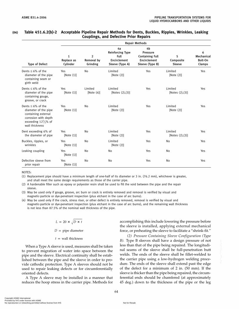
(06)
ASME B31.4-2006 PIPELINE TRANSPORTATION SYSTEMS FORLIQUID HYDROCARBONS AND OTHER LIQUIDS
Table 451.6.2(b)-2 Acceptable Pipeline Repair Methods for Dents, Buckles, Ripples, Wrinkles, LeakingCouplings, and Defective Prior Repairs
Repair Methods
4a 4bReinforcing Type Pressure 6
1 2 Full Containing Full 5 MechanicalReplace as Removal by Encirclement Encirclement Composite Bolt-On
Type of Defect Cylinder Grinding Sleeve (Type A) Sleeve (Type B) Sleeve Clamps
Dents ≤ 6% of the Yes No Limited Yes Limited Yesdiameter of the pipe [Note (1)] [Note (2)] [Note (2)]containing seam orgirth weld
Dents ≤ 6% of the Yes Limited Limited Yes Limited Yesdiameter of the pipe [Note (1)] [Note (4)] [Notes (2),(3)] [Notes (2),(3)]containing gouge,groove, or crack
Dents ≤ 6% of the Yes No Limited Yes Limited Yesdiameter of the pipe [Note (1)] [Note (2)] [Note (2)]containing externalcorrosion with depthexceeding 121⁄2% ofwall thickness
Dent exceeding 6% of Yes No Limited Yes Limited Yesthe diameter of pipe [Note (1)] [Note (2)] [Notes (2),(3)]
Buckles, ripples, or Yes No Limited Yes No Yeswrinkles [Note (1)] [Note (2)]
Leaking coupling Yes No No Yes No Yes[Note (1)]
Defective sleeve from Yes No No Yes No Yesprior repair [Note (1)]
NOTES:(1) Replacement pipe should have a minimum length of one-half of its diameter or 3 in. (76.2 mm), whichever is greater,
and shall meet the same design requirements as those of the carrier pipe.(2) A hardenable filler such as epoxy or polyester resin shall be used to fill the void between the pipe and the repair
sleeve.(3) May be used only if gouge, groove, arc burn or crack is entirely removed and removal is verified by visual and
magnetic-particle or dye-penetrant inspection (plus etchant in the case of arc burns).(4) May be used only if the crack, stress riser, or other defect is entirely removed, removal is verified by visual and
magnetic-particle or dye-penetrant inspection (plus etchant in the case of arc burns), and the remaining wall thicknessis not less than 87.5% of the nominal wall thickness of the pipe.
L p 20 � �D � t
D p pipe diameter
t p wall thickness
When a Type A sleeve is used, measures shall be takento prevent migration of water into space between thepipe and the sleeve. Electrical continuity shall be estab-lished between the pipe and the sleeve in order to pro-vide cathodic protection. Type A sleeves should not beused to repair leaking defects or for circumferentiallyoriented defects.
A Type A sleeve may be installed in a manner thatreduces the hoop stress in the carrier pipe. Methods for
64
accomplishing this include lowering the pressure beforethe sleeve is installed, applying external mechanicalforce, or preheating the sleeve to facilitate a “shrink-fit.”
(2) Pressure Containing Sleeve Configuration (TypeB). Type B sleeves shall have a design pressure of notless than that of the pipe being repaired. The longitudi-nal seams of the sleeve shall be full-penetration buttwelds. The ends of the sleeve shall be fillet-welded tothe carrier pipe using a low-hydrogen welding proce-dure. The ends of the sleeve shall extend past the edgeof the defect for a minimum of 2 in. (50 mm). If thesleeve is thicker than the pipe being repaired, the circum-ferential ends should be chamfered (at approximately45 deg.) down to the thickness of the pipe or the leg
Copyright ASME International Provided by IHS under license with ASME
Not for ResaleNo reproduction or networking permitted without license from IHS
--`,,```,,,,````-`-`,,`,,`,`,,`---

PIPELINE TRANSPORTATION SYSTEMS FOR ASME B31.4-2006LIQUID HYDROCARBONS AND OTHER LIQUIDS
length of the fillet weld on the end of the sleeve shouldnot be allowed to exceed the thickness of the carrierpipe by more than 1⁄16 in. (1.6 mm). Also, the leg lengthof the fillet weld on the end of the sleeve should not beless than the thickness of the carrier pipe minus 1⁄16 in.(1.6 mm). Special consideration shall be given to mini-mize stress concentration resulting from the repair.
Type B sleeves may be used for leaking or nonleakingdefects including circumferentially oriented defects.When multiple sleeves are used, a Type B sleeve shouldnot be terminated within one-half of a pipe diameterof, or 4 in. from a girth weld, whichever is greater. Thedistance between sleeves should be at least one pipediameter. Separated sleeves may be spaced less than onepipe diameter apart if joined by a welded bridging sleeveor made continuous by butt-welding them together.When installed at a nonleaking defect, a Type B sleevemay be installed in a manner that reduces the hoopstress in the carrier pipe. Methods for accomplishingthis include lowering the pressure before the sleeve isinstalled, applying external mechanical force, or pre-heating the sleeve to facilitate a “shrink-fit.”
(e) Composite Sleeve. Nonleaking corroded areas andcertain other types of defects may be repaired by theinstallation of a composite sleeve provided that designand installation methods are proven for the intendedservice prior to application. A qualified written proce-dure performed by trained personnel is required andrecords shall be retained in accordance with para. 455.A composite sleeve must have been tested to determineif it is compatible with cathodic protection and the prod-uct in the carrier pipe. The composite sleeve must alsoretain its essential properties in a moist environment attemperatures within the operational temperature rangeof the pipe. The load carrying capacity of the remainingpipe and the composite sleeve shall be at a minimumequal to the nominal load carrying capacity of the pipe.Composite sleeves should be marked and/or docu-mented as to location so that it will be evident that arepair has been made at the specific location.
Composite sleeves shall not be used to repair leaks,metal loss with a depth greater than 80% of the nominalwall thickness, cracks, or circumferentially orienteddefects.
Composite sleeves may be used to repair defects thathave been removed by grinding.
(f) Mechanical Bolt-on-Clamp. Repairs may be made toboth leaking and non-leaking defects by the installationof a mechanically applied clamp. A mechanical clampshall have a design pressure of not less than that of thepipe being repaired. Mechanical clamps shall not beused to repair circumferentially oriented defects unlessdesigned to withstand the axial load. A mechanicalclamp may be fully welded, both circumferentially andlongitudinally and seal welded at the bolts. The clampends shall extend past the edges of the defect for a
65
minimum of 2 in. (50 mm). Mechanically applied fullencirclement repair fittings shall meet the designrequirements of para. 401.2.
(g) Hot Tapping. Defects may be removed by hot tap-ping. When hot tapping is used as a means of repair,the portion of piping containing the defect shall be com-pletely removed. Hot tap fittings larger than 2 in.(50 mm) that have integral material sufficient to satisfythe area replacement requirements of para. 404.3.1(d)may not have adequate resistance to external forces andmoments if used without full-encirclement rein-forcement.
(h) Fittings. Minor leaks resulting from external cor-rosion and small externally corroded areas may berepaired by the installation of a welded fitting. Weldedfittings used to cover pipeline defects shall not exceedNPS 3 and shall have a design pressure of not less thanthe pipe being repaired. Pipe containing arc burns,grooves, and gouges may be repaired with a weldedfitting if the arc burn or stress riser associated with thegouge or groove is removed by grinding. No crack shallbe repaired by this method.
(i) Patches and Half Soles. Neither patches nor halfsoles shall be installed on pipelines.
451.6.2.10 Temporary Repairs. Temporary repairsmay be necessitated for operating purposes. Such tem-porary repairs shall be made in a safe manner and inaccord with sound engineering principles. Temporaryrepairs shall be made permanent or replaced in a perma-nent manner as soon as practical in accordance with thisCode.
451.6.3 Testing Repairs to Pipelines Operating at aHoop Stress of More Than 20% of the Specified MinimumYield Strength of the Pipe. When a scheduled repairto a pipeline is made by cutting out a section of the pipeas a cylinder and replacing it with another section ofpipe, the replacement section of pipe shall be subjectedto a pressure test. The replacement section of pipe shallbe tested as required for a new pipeline in accordancewith para. 437.4.1. The tests may be made on the pipeprior to installation provided radiographic or otheracceptable nondestructive tests (visual inspectionexcepted) are made on all tie-in butt welds after instal-lation.
451.8 Valve Maintenance
Pipeline block valves shall be inspected, servicedwhere necessary, and partially operated at least onceeach year to assure proper operating conditions.
451.9 Railroads and Highways Crossing ExistingPipelines
(a) When an existing pipeline is to be crossed by anew road or railroad, the operating company shall ana-lyze the pipeline in the area to be crossed in terms ofthe new anticipated external loads. If the sum of the
Copyright ASME International Provided by IHS under license with ASME
Not for ResaleNo reproduction or networking permitted without license from IHS
--`,,```,,,,````-`-`,,`,,`,`,,`---

(06)
ASME B31.4-2006 PIPELINE TRANSPORTATION SYSTEMS FORLIQUID HYDROCARBONS AND OTHER LIQUIDS
circumferential stresses caused by internal pressure andnewly imposed external loads (including both live anddead loads) exceeds 0.90 SMYS (specified minimumyield strength), the operating company shall installmechanical reinforcement, structural protection, or suit-able pipe to reduce the stress to 0.90 SMYS or less, orredistribute the external loads acting on the pipeline.API RP 1102 provides methods that may be used todetermine the total stress caused by internal pressureand external loads. API RP 1102 also provides methodsto check cyclic stress components for fatigue.
(b) Installation of uncased carrier pipe is preferred.Adjustments of existing pipelines in service at a pro-posed railroad or highway crossing shall conform todetails contained in API RP 1102. As specified in para.461.1.2(f), if casing is used, coated carrier pipe shall beindependently supported outside each end of the casingand insulated from the casing throughout the cased sec-tion, and casing ends shall be sealed using a durable,electrically nonconductive material.
(c) Testing and inspection of replaced pipe sectionsshall conform to requirements of para. 451.6.3. All newgirth welds in the carrier pipe shall be radiographed orinspected by other acceptable nondestructive methods(visual inspection excepted).
451.10 Inland Waters Platform Risers
Riser installations shall be visually inspected annuallyfor physical damage and corrosion in the splash zoneand above. The extent of any observed damage shall bedetermined, and, if necessary, the riser installation shallbe repaired or replaced.
451.11 Leak Detection
While in operation, all pipe segments should be peri-odically monitored to ensure they are not leaking.On-site personnel, both as neighbors of the pipelinesystem and as operator employees, discover many leaks.Operators should continue to communicate and main-tain the detection and response skills necessary to sup-port visual inspection of the pipeline system. Inaddition, operators should consider supplemental leakdetection methods other than visual.
Selection and implementation of the leak detectionsystem should take into account the risk of both thelikelihood and consequence of a leak. Some factors thatcould reduce the risk when an operator is determiningthe type and frequency of monitoring to employ includethe following:
(a) service — clean, noncorrosive, low vapor pressureliquids
(b) location — away from population, on operator-controlled property, away from areas that would sufferirreparable damage, not near waterways supporting rec-reational or commercial traffic
(c) construction — material operating well belowthreshold limits
66
(d) operating at low stress levels(e) leak history — indicates years with no leaksResponse time expected during a leak or emergency
is another important factor that should be considered.Longer response time supports the benefit of fasterdetection needs. Accuracy of detection and lack of falseindications are also factors that support or diminish thereliability of the leak detection method selected.
The operator should carefully select leak detectionsystems. The detection system can consist of regularlyscheduled right of way patrol, aerial, land or water;analysis of blocked-in pressures; monitoring changes offlow or pressure from steady state operation; volumetricline balances; pressure wave analysis, or any othermethod capable of detecting leakage in a timely manner.Monitoring intervals vary from continuous with compu-terized evaluation software, to range from weekly todaily for visual observation methods. If computer-basedmonitoring is utilized, API RP 1130 should be followed.
Whatever method is selected, operators should moni-tor and analyze their leak performance periodically andmake adjustments to the leak detection method selectedto reduce the leakage.
452 PUMP STATION, TERMINAL, AND TANK FARMOPERATION AND MAINTENANCE
452.1 General
(a) Starting, operating, and shutdown procedures forall equipment shall be established and the operatingcompany shall take appropriate steps to see that theseprocedures are followed. These procedures shall outlinepreventive measures and systems checks required toensure the proper functioning of all shutdown, control,and alarm equipment.
(b) Pipeline equipment located on operator propertyshould be monitored regularly for indications of leaks.The operator should evaluate the alternatives available,giving consideration to the following:
(1) monitoring systems such as gas detectors, sumplevel alarms, pump seal failure alarms, high level alarmsof tanks and storage vessels
(2) observation patrols or operational checks con-ducted on an hourly, daily, weekly, or monthly scheduleappropriate for the locations factors
(3) periodic static pressure tests of piping and stor-age tanks
(4) careful evaluation of routine operating volumet-ric receipt, delivery, and inventory reports
(5) fugitive emission testing of seal and glands(6) public awareness programs to enhance recogni-
tion and response to leaks, etc.The periodic review and analysis of leaks that have
occurred on the operator ’s property should be con-ducted to identify corrective actions.
(06)
Copyright ASME International Provided by IHS under license with ASME
Not for ResaleNo reproduction or networking permitted without license from IHS
--`,,```,,,,````-`-`,,`,,`,`,,`---

PIPELINE TRANSPORTATION SYSTEMS FOR ASME B31.4-2006LIQUID HYDROCARBONS AND OTHER LIQUIDS
452.2 Controls and Protective Equipment
(a) Controls and protective equipment, includingpressure limiting devices, regulators, controllers, reliefvalves, and other safety devices, shall be subjected tosystematic periodic inspections and tests, at least annu-ally, except as provided in para. 452.2(b), to determinethat they are
(1) in good mechanical condition(2) adequate from the standpoint of capacity and
reliability of operation for the service in which they areemployed
(3) set to function at the correct pressure(4) properly installed and protected from foreign
materials or other conditions that might prevent properoperation
(b) Relief valves on pressure storage vessels con-taining LPG, carbon dioxide, or liquid anhydrousammonia shall be subjected to tests at least every 5 years.
452.3 Storage Vessels
(a) Storage vessels, including atmospheric and pres-sure tanks, handling the liquid or liquids being trans-ported shall be periodically inspected and pertinentrecords maintained. Points to be covered include
(1) stability of foundation(2) condition of bottom, shell, stairs, roof(3) venting or safety valve equipment(4) condition of firewalls or tank dikes
(b) Storage vessels and tanks shall be cleaned in accor-dance with API Publ. 2015.
452.4 Storage of Combustible Materials
All flammable or combustible materials in quantitiesbeyond those required for everyday use or other thanthose normally used in pump houses shall be stored ina separate structure built of noncombustible materiallocated a suitable distance from the pump house. Allaboveground oil or gasoline storage tanks shall be pro-tected in accordance with NFPA 30.
452.5 Fencing
Station, terminal, and tank farm areas shall be main-tained in a safe condition, and shall be fenced andlocked, or attended, for the protection of the propertyand the public.
452.6 Signs
(a) Suitable signs shall be posted to serve as warningsin hazardous areas.
(b) Classified and high voltage areas shall be ade-quately marked and isolated.
(c) Caution signs shall be displayed indicating nameof the operating company and, where possible, an emer-gency telephone contact.
67
452.7 Prevention of Accidental Ignition
(a) Smoking shall be prohibited in all areas of a pumpstation, terminal, or tank farm in which the possibleleakage or presence of vapor constitutes a hazard of fireor explosion.
(b) Flashlights or hand lanterns, when used, shall beof the approved type.
(c) Welding shall commence only after compliancewith para. 434.8.1(c).
(d) Consideration should be given to the preventionof other means of accidental ignition. See NACERP-01-77 for additional guidance.
453 CORROSION CONTROL
Protection of ferrous pipe and components from exter-nal and internal corrosion, including tests, inspections,and appropriate corrective measures, shall be as pre-scribed in Chapter VIII.
454 EMERGENCY PLAN
(a) A written Emergency Plan shall be established forimplementation in the event of system failures, acci-dents, or other emergencies, and shall include proce-dures for prompt and expedient remedial actionproviding for the safety of the public and operatingcompany personnel, minimizing property damage, pro-tecting the environment, and limiting accidental dis-charge from the piping system.
(b) The Plan shall provide for acquainting and train-ing of personnel responsible for the prompt executionof emergency action. Personnel shall be informed con-cerning the characteristics of the liquid in the pipingsystems and the safe practices in the handling of acciden-tal discharge and repair of the facilities, with emphasison the special problems and additional precautions inthe handling of leaks and repair of systems transportingLPG, carbon dioxide, or liquid anhydrous ammonia. Theoperating company shall establish scheduled reviewswith personnel of procedures to be followed in emergen-cies at intervals not exceeding 6 months, and reviewsshall be conducted such that they establish the compe-tence of the Emergency Plan.
(c) Procedures shall cover liaison with state and localcivil agencies such as fire departments, police depart-ments, sheriff’s offices, and highway patrols, to provideprompt intercommunications for coordinated remedialaction; dissemination of information on location of sys-tem facilities; characteristics of the liquids transported,including additional precautions necessary with leaksfrom piping systems transporting LPG, carbon dioxide,or liquid anhydrous ammonia; and joint preparation ofcooperative action as necessary to assure the safety ofthe public in the event of emergencies.
Copyright ASME International Provided by IHS under license with ASME
Not for ResaleNo reproduction or networking permitted without license from IHS
--`,,```,,,,````-`-`,,`,,`,`,,`---
ASME B31.4-2006 PIPELINE TRANSPORTATION SYSTEMS FORLIQUID HYDROCARBONS AND OTHER LIQUIDS
(d) A line of communications shall be establishedwith residents along the piping system to recognize andreport a system emergency to the appropriate operatingcompany personnel. This could include supplying acard, sticker, or equivalent with names, addresses, andtelephone numbers of operating company personnel tobe contacted.
(e) In the formulation of emergency procedures forlimiting accidental discharge from the piping system,the operating company shall give consideration to
(1) formulating and placing in operation proce-dures for an area cooperative pipeline leak notificationemergency action system between operating companieshaving piping systems in the area
(2) reduction of pipeline pressure by ceasing pump-ing operations on the piping system, opening the systemto delivery storage on either side of the leak site, andexpeditious closing of block valves on both sides of theleak site, and in the case of systems transporting LPG,continuation of pumping until LPG has been replacedat point of leak by a less volatile product if vapors arenot accumulating to an extent that a serious hazardappears imminent
(3) interim instructions to local authorities prior toarrival of qualified operating company personnel at theleak site
(4) rapid transportation of qualified personnel tothe leak site
(5) minimization of public exposure to injury andprevention of accidental ignition by evacuation of resi-dents and the halting of traffic on roads, highways, andrailroads in the affected area
(6) in the case of systems transporting LPG, assess-ment of extent and coverage of the LPG vapor cloudand determination of hazardous area with portableexplosimeters; ignition of vapors at leak site to preventthe uncontrolled spread of vapors; utilization of tempo-rary flares or blowdowns on either side of the leak site;and utilization of internal plugging equipment whereit is anticipated that vaporization of LPG entrapped inpipeline segment will continue over a prolonged period
(7) in the case of systems transporting liquid anhy-drous ammonia, assessment of the extent and coverageof the ammonia vapor cloud and utilization of internalplugging equipment where it is anticipated that vapor-ization of liquid anhydrous ammonia entrapped in thepipeline segment will continue over a prolonged period
(8) In the case of systems transporting carbon diox-ide, assessment of the carbon dioxide released, it effects,and the use of existing means to blow down and controlthe spread of it at the leak site
455 RECORDS
For operation and maintenance purposes, the follow-ing records shall be properly maintained:
68
(a) necessary operational data(b) pipeline patrol records(c) corrosion records as required under para. 465(d) leak and break records(e) records pertaining to routine or unusual inspec-
tions, such as external or internal line conditions(f) pipeline repair records
456 QUALIFYING A PIPING SYSTEM FOR AHIGHER OPERATING PRESSURE
(a) In the event of up-rating an existing piping systemwhen the higher operating pressure will produce a hoopstress of more than 20% of the specified minimum yieldstrength of the pipe, the following investigative andcorrective measures shall be taken:
(1) the design and previous testing of the pipingsystem and the materials and equipment in it bereviewed to determine that the proposed increase inmaximum steady state operating pressure is safe andin general agreement with the requirements of this Code;
(2) the conditions of the piping system be deter-mined by leakage surveys and other field inspections,examination of maintenance and corrosion control rec-ords, or other suitable means;
(3) repairs, replacements, or alterations in the pip-ing system disclosed to be necessary by steps (1) and(2) be made.
(b) The maximum steady state operating pressuremay be increased after compliance with para. 456(a) andone of the following provisions:
(1) If the physical condition of the piping systemas determined by (a) above indicates that the system iscapable of withstanding the desired increased maximumsteady state operating pressure in accordance with thedesign requirement of this Code, and the system haspreviously been tested for a duration and to a pressureequal to or greater than required in paras. 437.4.1(a) and(c) for a new piping system for the proposed highermaximum steady state operating pressure, the systemmay be operated at the increased maximum steady stateoperating pressure.
(2) If the physical condition of the piping systemas determined by (a) above indicates that the ability ofthe system to withstand the increased maximum steadystate operating pressure has not been satisfactorily veri-fied, or the system has not been previously tested to thelevels required by this Code for a new piping system forthe proposed higher maximum steady state operatingpressure, the system may be operated at the increasedmaximum steady state operating pressure if the systemshall successfully withstand the test required by thisCode for a new system to operate under the sameconditions.
Copyright ASME International Provided by IHS under license with ASME
Not for ResaleNo reproduction or networking permitted without license from IHS
--`,,```,,,,````-`-`,,`,,`,`,,`---

PIPELINE TRANSPORTATION SYSTEMS FOR ASME B31.4-2006LIQUID HYDROCARBONS AND OTHER LIQUIDS
(c) In no case shall the maximum steady stateoperating pressure of a piping system be raised to avalue higher than the internal design pressure permittedby this Code for a new piping system constructed ofthe same materials. The rate of pressure increase to thehigher maximum allowable steady state operating pres-sure should be gradual so as to allow sufficient time forperiodic observations of the piping system.
(d) Records of such investigations, work performed,and pressure tests conducted shall be preserved as longas the facilities involved remain in service.
69
457 ABANDONING A PIPING SYSTEM
In the event of abandoning a piping system, it isrequired that
(a) facilities to be abandoned in place shall be discon-nected from all sources of the transported liquid, suchas other pipelines, meter stations, control lines, and otherappurtenances
(b) facilities to be abandoned in place shall be purgedof the transported liquid and vapor with an inert mate-rial and the ends sealed
Copyright ASME International Provided by IHS under license with ASME
Not for ResaleNo reproduction or networking permitted without license from IHS
--`,,```,,,,````-`-`,,`,,`,`,,`---

ASME B31.4-2006
Chapter VIIICorrosion Control
460 GENERAL
(a) This Chapter prescribes minimum requirementsand procedures for protection of ferrous pipe and com-ponents from external and internal corrosion, and isapplicable to new piping installations and existing pip-ing systems.
(b) External and internal corrosion shall be controlledconsistent with condition of the piping system and theenvironment in which the system is located by applica-tion of these corrosion control requirements and proce-dures. Application of some corrosion control practicesrequires a significant amount of competent judgment inorder to be effective in mitigating corrosion, and devia-tion from the provisions of this Chapter is permissiblein specific situations, provided the operating companycan demonstrate that the objectives expressed hereinhave been achieved. For carbon dioxide systems, it shallbe recognized that water can combine with carbon diox-ide to form a compound that may be corrosive underpipeline conditions.
(c) Corrosion control requirements and proceduresmay in many instances require measures in addition tothose shown herein. Therefore, each operating companyshall establish procedures to implement the require-ments of this Chapter. Procedures, including those fordesign, installation, and maintenance of cathodic protec-tion systems, shall be prepared and carried out by, orunder the direction of, persons qualified by training orexperience in corrosion control methods. NACE RP-01-69 or NACE RP-06-75 provides a guide for proceduresto implement requirements herein and to monitor andmaintain cathodic protection systems.
(d) Corrosion personnel shall be provided equipmentand instrumentation necessary to accomplish the work.
(e) Coating crews and inspectors shall be suitablyinstructed and provided with equipment necessary tocoat and inspect the pipe and components.
461 EXTERNAL CORROSION CONTROL FORBURIED OR SUBMERGED PIPELINES
461.1 New Installations
461.1.1 General(a) Control of external corrosion of new buried or
submerged piping systems shall be provided for eachcomponent in the system except where the operatingcompany can demonstrate by tests, investigations, or
70
experience in the area of application that a detrimentalcorrosive environment does not exist. However, within12 months after installation, the operating companyshall electrically inspect the buried or submerged sys-tem. If the electrical inspection indicates that a corrosivecondition exists, the piping system shall be cathodicallyprotected. If cathodic protection is not installed, the pip-ing system shall be electrically inspected at intervals notexceeding 5 years, and the system shall be cathodicallyprotected if electrical inspection indicates that a corro-sive condition exists.
(b) Control of external corrosion of buried or sub-merged pipe and components in new installations(including new pump stations, tank farms, and termi-nals, and relocating, replacing, or otherwise changingexisting piping systems) shall be accomplished by theapplication of an effective protective coating supple-mented with cathodic protection and suitable drainagebonds in stray current areas. Materials shall be selectedwith due regard to the type of supplemental corrosionprotection and to the environment.
(c) Where impractical, and where adequate provi-sions for corrosion control have been made, the mini-mum clearance of 12 in. (300 mm) between the outsideof any pipe installed underground and the extremityof any other underground structure specified in para.434.6(c) may be reduced.
461.1.2 Protective Coating(a) Protective coatings used on buried or submerged
pipe and components shall have the following character-istics:
(1) mitigate corrosion(2) have sufficient adhesion to the metal surface to
effectively resist underfilm migration of moisture(3) be ductile enough to resist cracking(4) have strength sufficient to resist damage due to
handling and soil stress(5) have properties compatible with any supple-
mental cathodic protection(b) Welds shall be inspected for irregularities that
could protrude through the pipe coating, and any suchirregularities shall be removed.
(c) Pipe coating shall be inspected, both visually andby an electric holiday detector, just prior to: loweringpipe into ditch, applying a weight coating if used, orsubmerging the pipe if no weight coating is used. Anyholiday or other damage to the coating detrimental to
Copyright ASME International Provided by IHS under license with ASME
Not for ResaleNo reproduction or networking permitted without license from IHS
--`,,```,,,,````-`-`,,`,,`,`,,`---

(06)
(06)
PIPELINE TRANSPORTATION SYSTEMS FOR ASME B31.4-2006LIQUID HYDROCARBONS AND OTHER LIQUIDS
effective corrosion control shall be repaired andreinspected.
(d) Insulating type coating, if used, shall have lowmoisture absorption characteristics and provide highelectrical resistance. Insulating coatings shall beinspected in accordance with established practices atthe time of application and just prior to lowering pipeinto ditch, and defects shall be repaired and reinspected.
(e) Pipe shall be handled and lowered into ditch orsubmerged so as to prevent damage after the electricalinspection. Pipe coating shall be protected from low-ering-in damage in rough or detrimental environment byuse of rock shield, ditch padding, or any other suitableprotective measures.
(f) If coated pipe is installed by boring, directionaldrilling, driving, or other similar method, precautionsshall be taken to minimize damage to the coating duringinstallation. If casing is used (see paras. 434.13.4 and451.9), carrier pipe shall be independently supportedoutside each end of the casing and insulated from thecasing throughout the length of cased section, and casingends shall be sealed using a durable, electrically noncon-ductive material.
(g) The backfilling operation shall be inspected forquality, compaction, and placement of material to pre-vent damage to pipe coating.
(h) Where a connection is made to a coated pipe, alldamaged coating shall be removed and new coatingapplied on the attachments as well as on the pipe.
(i) Coating selection for pipe and field joints includedin directionally drilled crossings shall be selected towithstand the frictional and abrasive forces exerted onthe pipe during installation.
461.1.3 Cathodic Protection System(a) A cathodic protection system provided by a gal-
vanic anode or impressed current anode system shallbe installed that will mitigate corrosion and contain amethod of determining the degree of cathodic protectionachieved on the buried or submerged piping system.
(b) A cathodic protection system shall be installed notlater than 1 year after completion of construction.
(c) Cathodic protection shall be controlled so as notto damage the protective coating, pipe, or components.
(d) Owners of known underground structures whichmay be affected by installation of a cathodic protectionsystem shall be notified of said installation, and, wherenecessary, joint bonding surveys shall be conducted byparties involved.
(e) Electrical installations shall be made in accordancewith the National Electrical Code, NFPA 70, API RP500C, and applicable local codes.
461.1.4 Electrical Isolation(a) Buried or submerged coated piping systems shall
be electrically isolated at all interconnections with for-eign systems, except where arrangements are made for
71
mutual cathodic protection or where undergroundmetallic structures are electrically interconnected andcathodically protected as a unit.
(b) An insulating device shall be installed where elec-trical isolation of a portion of a piping system frompump stations, storage tanks, and similar installationsis necessary to facilitate the application of corrosioncontrol. The insulating device shall not be installedwhere a combustible atmosphere is anticipated unlessprecautions are taken to prevent arcing.
(c) Consideration shall be given to the prevention ofdamage to piping systems due to lightning or fault cur-rents when installed in close proximity to electric trans-mission tower footings, ground cables, or counterpoise.See NACE RP-01-77 for guidance when ac interferenceproblems are suspected. Studies in collaboration withthe operator of such electric transmission systems shallbe made on common problems of corrosion and elec-trolysis.
(d) Electrical tests shall be made to locate any uninten-tional contacts with underground metallic structures,and, if such contacts exist, each one shall be corrected.
(e) When a pipeline is separated, a bonding conductorof sufficient current carrying capacity shall be installedacross the points of separation and retained during theperiod of separation.
461.1.5 Test Leads(a) Except where impractical in wet marsh areas, suffi-
cient test leads shall be installed on all buried or sub-merged coated piping systems for taking electricalmeasurements to indicate adequacy of the cathodic pro-tection.
(b) Test leads shall be installed as follows:(1) Special attention shall be given to the manner
of installation of test leads used for corrosion control ortesting, and leads shall be attached to the pipe in suchmanner as to minimize stress and prevent surface cracksin the pipe. Leads may be attached directly on the pipewith the low temperature welding process using alumi-num powder and copper oxide and limiting the chargeto a 15 g cartridge, or with soft solders or other materialsthat do not involve temperatures exceeding those forsoft solders.
(2) Slack shall be provided to prevent test leadsfrom being broken or damaged during backfilling.
(3) Leads shall be insulated from the conduit inwhich they are contained.
(4) Bond points shall be made watertight, andbared test lead wires, pipe, and components shall beprotected by electrical insulating material compatiblewith original wire insulation and pipe coating.
461.1.6 Electrical Interference(a) If an impressed current type cathodic protection
system is used, the anodes shall be located so as to
Copyright ASME International Provided by IHS under license with ASME
Not for ResaleNo reproduction or networking permitted without license from IHS
--`,,```,,,,````-`-`,,`,,`,`,,`---

ASME B31.4-2006 PIPELINE TRANSPORTATION SYSTEMS FORLIQUID HYDROCARBONS AND OTHER LIQUIDS
minimize adverse effect on existing underground metal-lic structures.
(b) The possibility of external corrosion induced bystray electrical currents in the earth shall be recognized.See NACE RP-01-69 and NACE RP-01-77 for additionalguidance. These stray currents are generated by sourcesremote from, and independent of, the piping system, andare more predominant in highly industrialized areas,mining regions, and locales containing high voltage dcelectrical power ground beds. Foreign company pipelinecathodic protection systems are also a common sourceof stray earth currents. The protection of the pipingsystem against stray current induced corrosion shall beprovided by metallic bonds, increased cathodic protec-tion, supplemental protective coatings, insulatingflanges, or galvanic anodes.
461.2 Existing Piping Systems
The operating company shall establish procedures fordetermining the external condition of its existing buriedor submerged piping systems and take action appro-priate for the conditions found, including, but not lim-ited to, the following:
(a) Examine and study records available from previ-ous inspections and conduct additional inspectionswhere the need for additional information is indicated.The type, location, number, and frequency of suchinspections shall be determined by consideration of suchfactors as knowledge of the condition of the piping sys-tem and environment, and public or employee safety inthe event of leakage. Corrective measures shall be inaccordance with para. 464.
(b) Install cathodic protection on all buried or sub-merged piping systems that are coated with an effectiveexternal surface coating material, except at pump sta-tions, tank farms, and terminals. All buried or sub-merged piping at pump stations, tank farms, andterminals shall be electrically inspected and cathodicprotection installed or augmented where necessary.
(c) Operating pressures on bare piping systems shallnot be increased until they are electrically inspected andother appropriate actions are taken regarding conditionof pipe and components. The requirements of para. 456shall also be complied with in the event of up-rating.
461.3 Monitoring
(a) Cathodic protection facilities for new or existingpiping systems shall be maintained in a serviceable con-dition, and electrical measurements and inspections ofcathodically protected buried or submerged piping sys-tems, including tests for stray electrical currents, shallbe conducted at least each calendar year, but with inter-vals not exceeding 15 months, to determine that thecathodic protection system is operating properly andthat all buried or submerged piping is protected in accor-dance with applicable criteria. Appropriate corrective
72
measures shall be taken where tests indicate that ade-quate protection does not exist.
(b) Evidence of adequate level of cathodic protectionshall be by one or more of the criteria listed in Criteriafor Cathodic Protection, Section 6 in NACE RP-01-69,or Section 5 in NACE RP-06-75.
(c) The type, number, location, and frequency of testsshall be adequate to establish with reasonable accuracythe degree of protection provided on all piping withinthe limits of each cathodic protection system, and shallbe determined by considering:
(1) age of the piping system and operating experi-ence, including bell hole inspections and leakage sur-vey data
(2) condition of pipe at time of application ofcathodic protection and method of applying protection
(3) corrosiveness of environment(4) probability of loss of protection due to activity
of other construction, reconstruction, or other causes inthe area
(5) method of applying cathodic protection anddesign life of cathodic protection installation
(6) public and employee safety(d) Test leads required for cathodic protection shall
be maintained so that electrical measurements can beobtained to insure adequate protection.
(e) Cathodic protection rectifiers or other impressedcurrent power source shall be inspected at intervals notexceeding 2 months.
(f ) All connected protective devices, includingreverse current switches, diodes, and interference bonds,failure of which would jeopardize structure protection,shall be checked at intervals not exceeding 2 months.Other interference bonds shall be checked at least eachcalendar year but at intervals not exceeding 15 months.
(g) Bare components in a piping system that are notprotected by cathodic protection shall be electricallyinspected at intervals not exceeding 5 years. The resultsof this inspection and leak records for the piping compo-nents inspected shall be analyzed to determine the loca-tion of localized active corrosion areas. Cathodicprotection shall be applied at such areas. Inspectionsand analysis of leak and repair records shall be repeatedat intervals not exceeding 5 years.
(h) Buried or submerged piping components exposedfor any reason shall be examined for indications of exter-nal corrosion. Discovery of active corrosion, general pit-ting of the component’s surface, or a leak caused bycorrosion shall be investigated further to determine thecause and extent of the corrosion and whether cathodicprotection shall be installed or augmented to mitigatecorrosion or whether piping system or portion thereofshall be treated as indicated in paras. 464(b), (c), and (d).
Copyright ASME International Provided by IHS under license with ASME
Not for ResaleNo reproduction or networking permitted without license from IHS
--`,,```,,,,````-`-`,,`,,`,`,,`---

PIPELINE TRANSPORTATION SYSTEMS FOR ASME B31.4-2006LIQUID HYDROCARBONS AND OTHER LIQUIDS
462 INTERNAL CORROSION CONTROL
462.1 New Installations
(a) Internal corrosion is recognized in the operationof liquid pipelines, and a commodity that will corrodethe internal surfaces of pipe and components in a pipingsystem shall not be transported unless the corrosiveeffect of the commodity has been investigated and ade-quate steps taken to mitigate internal corrosion. It isusually necessary to control internal corrosion in petro-leum products and liquefied petroleum gas pipelines toprotect product quality, preserve high line efficiencies,and prevent corrosion of internal surfaces. NACE RP-01-75 provides guidance. Frequent scraping, pigging, orsphering, dehydration, inhibition, or internal coatingmay be used to limit internal corrosion.
(b) If dehydration or inhibitors are used to controlinternal corrosion, sufficient coupon holders or othertypes of monitoring techniques shall be utilized to ade-quately determine the effectiveness of the internal corro-sion control program. Inhibitors shall be selected of atype that will not cause deterioration of any piping com-ponent and shall be used in sufficient quantity andproper quality necessary to mitigate internal corrosion.
(c) If internal coatings are used to control corrosion,they shall meet the quality specifications and minimumdry film thickness established in the industry and beinspected in accordance with industry recommendedpractices. Internal coatings shall include provisions forjoint protection on piping joined by welding or othermethods exposing parent metal at the joints, such as theuse of a suitable corrosion inhibitor.
(d) For purposes of this Code, liquid anhydrousammonia shall contain a minimum of 0.2% water byweight to inhibit stress corrosion cracking. Any addedwater must be made using steam condensate, deionized,or distilled water.
462.2 Existing Piping Systems
The operating company shall establish procedures fordetermining the corrosive effect of the commodity beingtransported, and the internal condition of its existingpiping systems, and take appropriate action for the con-ditions found, including, but not limited to, the fol-lowing.
Examine and study records available from previousinspections and conduct additional inspections andinvestigations where the need for additional informa-tion is indicated. Corrective measures shall be in accor-dance with para. 464.
462.3 Monitoring
(a) If scraping, pigging, or sphering, dehydration,inhibitors, or internal coating are used to control internalcorrosion in new or existing piping systems, couponsshall be examined or other monitoring techniques uti-lized at intervals not exceeding 6 months to determine
73
the effectiveness of the protective measures or the extentof any corrosion. Appropriate corrective measures shallbe taken where examinations or monitoring techniquesindicate that adequate protection does not exist.
(b) Whenever any pipe or component in a piping sys-tem can be visually examined internally, or pipe or com-ponent is removed from a piping system for any reason,the internal surfaces shall be inspected for evidence ofcorrosion, and if corrosion is found, the adjacent pipeor component shall be examined. Discovery of activecorrosion, general pitting of the pipe or component sur-face, or a leak caused by corrosion shall be investigatedfurther to determine the cause and extent of the corro-sion and whether steps shall be taken or augmented tomitigate corrosion or whether system or portion thereofshall be treated as indicated in paras. 464(b), (c), and (d).
463 EXTERNAL CORROSION CONTROL FOR PIPINGEXPOSED TO ATMOSPHERE
463.1 New Installations
Pipe and components that are exposed to the atmo-sphere shall be protected from external corrosion by useof corrosion resistant steel or application of protectivecoating or paint unless the operating company can dem-onstrate by test, investigation, or experience in area ofapplication that a corrosive atmosphere does not exist.Protective coating or paint shall be applied to a cleansurface and shall be suitable material to provide ade-quate protection from the environment.
463.2 Existing Piping Systems
Pipe and components in existing piping systems thatare exposed to the atmosphere shall be inspected inaccordance with a planned schedule and corrective mea-sures shall be taken in accordance with para. 464.
463.3 Monitoring
Protective coating or paint used to prevent corrosionof pipe and components exposed to the atmosphere shallbe maintained in a serviceable condition, and such pro-tective coating or paint, as well as bare pipe and compo-nents not coated or painted as permitted under para.463.1, shall be inspected at intervals not exceeding3 years. Appropriate corrective measures shall be takenin accordance with para. 464 where inspections indicatethat adequate protection does not exist.
464 CORRECTIVE MEASURES
(a) Criteria on corrosion limits and disposition of cor-roded pipe are specified in paras. 451.6.2(a)(6) and451.6.2(a)(7).
(b) Where inspections or leakage history indicate thatactive corrosion of metal is taking place in any portionof a piping system to the extent that a safety hazard is
Copyright ASME International Provided by IHS under license with ASME
Not for ResaleNo reproduction or networking permitted without license from IHS
--`,,```,,,,````-`-`,,`,,`,`,,`---

ASME B31.4-2006 PIPELINE TRANSPORTATION SYSTEMS FORLIQUID HYDROCARBONS AND OTHER LIQUIDS
likely to result, that portion of the system shall be treatedas specified in para. 451.6.2(a)(6) or (7), and the fol-lowing.
(1) In the case of external corrosion of buried orsubmerged piping, cathodic protection shall be installedor augmented to mitigate the external corrosion.
(2) In the case of internal corrosion of piping, stepsindicated in para. 462.1 shall be taken or augmented tomitigate the internal corrosion.
(3) In the case of external corrosion of pipingexposed to the atmosphere, protective coating or paintshall be repaired or applied to mitigate the externalcorrosion.
(c) Pipe that is replaced because of external corrosionshall be replaced with coated pipe if buried or sub-merged, and with corrosion resistant steel pipe or coatedor painted pipe if exposed to the atmosphere.
(d) If a portion of the piping system is repaired, recon-ditioned, or replaced, or operating pressure is reduced
74
because of external or internal corrosion, the need forprotection of that portion from such corrosion deteriora-tion shall be considered, and any indicated steps takento control the corrosion.
465 RECORDS
(a) Records and maps showing the location of cathod-ically protected piping, cathodic protection facilities,and neighboring structures affected by or affecting thecathodic protection system shall be maintained andretained for as long as the piping system remains inservice.
(b) Results of tests, surveys and inspections requiredby this Chapter shall be retained as needed to indicatethe adequacy of corrosion control measures. The mini-mum retention period shall be 2 years or until the resultsof subsequent inspections, tests, or surveys are received,whichever is longer.
Copyright ASME International Provided by IHS under license with ASME
Not for ResaleNo reproduction or networking permitted without license from IHS
--`,,```,,,,````-`-`,,`,,`,`,,`---

(06)
ASME B31.4-2006
Chapter IXOffshore Liquid Pipeline Systems
A400 GENERAL STATEMENTS
(a) Chapter IX pertains only to offshore pipeline sys-tems as defined in para. A400.1.
(b) This Chapter is organized to parallel the number-ing and content of the first eight chapters of the Code.Paragraph designations are the same as those in the firsteight chapters, with the prefix “A.”
(c) All provisions of the first eight chapters of theCode are also requirements of this Chapter unless specif-ically modified herein. If the text in this Chapter addsrequirements, the requirements in the original Chapterwith the same title and number also apply. If a provisionin this Chapter is in conflict with one or more provisionsin other chapters, the provision in this Chapter shallapply.
(d) It is the intent of this Chapter to provide require-ments for the safe and reliable design, installation, andoperation of offshore liquid pipeline systems. It is notthe intent of this Chapter to be all inclusive. Engineeringjudgment must be used to identify special considera-tions which are not specifically addressed. API RP 1111may be used as a guide. It is not the intent of this Chapterto prevent the development and application of newequipment and technology. Such activity is encouragedas long as the safety and reliability requirements of theCode are satisfied.
A400.1 Scope
This Chapter covers the design, material require-ments, fabrication, installation, inspection, testing, andsafety aspects of the operation and maintenance of off-shore pipeline systems. For purposes of this Chapter,offshore pipeline systems include offshore liquid pipe-lines, pipeline risers, offshore liquid pumping stations,pipeline appurtenances, pipe supports, connectors, andother components as addressed specifically in the Code.See Fig. 400.1.2.
A400.2 Definitions
Some of the more common terms relating to offshoreliquid pipelines are defined below.
buckle arrestor: any device attached to, or made a partof, the pipe for the purpose of arresting a propagatingbuckle.
buckle detector: any means for detecting dents, excessiveovalization, or buckles in a pipeline.
75
external hydrostatic pressure: pressure acting on any exter-nal surface resulting from its submergence in water.
flexible pipe: pipe which is(a) manufactured as a composite from both metal and
nonmetal components(b) capable of allowing large deflections without
adversely affecting the pipe’s integrity(c) intended to be an integral part of the permanent
liquid transportation systemFlexible pipe does not include solid metallic pipe,
plastic pipe, fiber reinforced plastic pipe, rubber hose, ormetallic pipes lined with nonmetallic linings or coatings.
hyperbaric weld: a weld performed at ambient hydrostaticpressure.
offshore: the area beyond the line of ordinary high wateralong that portion of the coast that is in direct contactwith the open seas and beyond the line marking theseaward limit of inland coastal waters.
offshore pipeline riser: the vertical or near-vertical portionof an offshore pipeline between the platform piping andthe pipeline at or below the seabed, including a lengthof pipe of at least five pipe diameters beyond the bottomelbow, bend, or fitting. Because of the wide variety ofconfigurations, the exact location of transition amongpipeline, pipeline riser, and platform piping must beselected on a case-by-case basis.
offshore pipeline system: includes all components of a pipe-line installed offshore for the purpose of transportingliquid, other than production facility piping. Tanker orbarge loading hoses are not considered part of the off-shore pipeline system.
offshore platform: any fixed or permanently anchoredstructure or artificial island located offshore.
pipe collapse: flattening deformation of the pipe resultingin loss of cross-sectional strength and circular shape,which is caused by excessive external hydrostatic pres-sure acting alone.
platform piping: on offshore platforms producing hydro-carbons, platform piping is all liquid transmission pip-ing and appurtenances between the production facilityand the offshore pipeline riser(s). On offshore platformsnot producing hydrocarbons, platform piping is all liq-uid transmission piping and appurtenances between therisers. Because of a wide variety of configurations, theexact location of the transition between the offshore
Copyright ASME International Provided by IHS under license with ASME
Not for ResaleNo reproduction or networking permitted without license from IHS
--`,,```,,,,````-`-`,,`,,`,`,,`---

ASME B31.4-2006 PIPELINE TRANSPORTATION SYSTEMS FORLIQUID HYDROCARBONS AND OTHER LIQUIDS
pipeline riser(s), platform piping, and production facilitymust be selected on a case-by-case basis.
propagating buckle: a buckle which progresses rapidlyalong a pipeline caused by the effect of external hydro-static pressure on a previously formed buckle, local col-lapse, or other cross-sectional deformation.
pull tube: a conduit attached to an offshore platformthrough which a riser can be installed.
pull-tube riser: riser pipe or pipes installed through apull tube (e.g., J tube or I tube).
riser: see offshore pipeline riser.
sea floor bathymetry: refers to water depths along thepipeline route.
splash zone: the area of the pipeline riser or other pipelinecomponents that is intermittently wet and dry due towave and tidal action.
trawl board: a structure that is attached to the bottomof commercial fishing nets and is dragged along thesea floor.
vortex shedding: the periodic shedding of fluid vorticesand resulting unsteady flow patterns downstream of apipeline span.
A401 DESIGN CONDITIONS
A401.1 General
A401.1.1 Offshore Design Conditions. A number ofphysical parameters, henceforth referred to as designconditions, govern design of the offshore pipeline sys-tem so that it meets installation, operation, and otherpost-installation requirements. Some of the conditionswhich may influence the safety and reliability of anoffshore pipeline system are
(a) pressure(b) temperature(c) waves(d) current(e) seabed(f) wind(g) ice(h) seismic activity(i) platform motion(j) water depth(k) support settlement(l) accidental loads(m) marine vessel activity(n) fishing/recreational activitiesThe design of an offshore pipeline system is often
controlled by installation considerations rather than byoperating load conditions.
76
A401.9 Installation Design Considerations
A401.9.1 Loads for Installation Design. The designof an offshore pipeline system suitable for safe installa-tion and the development of offshore pipeline construc-tion procedures shall be based on consideration of theparameters listed in paras. A401.9.2 and A401.9.3. Theseparameters shall be considered to the extent that theyare significant to the proposed system and applicableto the method of installation being considered.
All parts of the offshore pipeline system shall bedesigned for the most critical combinations of installa-tion and environmental loads, acting concurrently, towhich the system may be subjected.
A401.9.2 Installation Loads. Installation loadswhich shall be considered are those imposed on thepipeline system under anticipated installation condi-tions, excluding those resulting from environmental con-ditions.
Loads which should be considered as installationloads include
(a) weight, including (as appropriate) the weight of(1) pipe(2) coatings and their absorbed water(3) attachments to the pipe(4) fresh water or sea water content (if pipe is
flooded during installation)(b) buoyancy(c) external pressure(d) static loads imposed by construction equipmentWhen considering the effect of pipe and/or pipeline
component weights (in air and submerged) on installa-tion stresses and strains, the variability due to weightcoating, manufacturing tolerances, and water absorp-tion shall also be considered.
A401.9.3 Environmental Loads During Installation.Environmental loads which shall be considered are thoseimposed on the pipeline system by environmental condi-tions. Loads which should be considered under this cate-gory include, as appropriate, those arising due to
(a) waves(b) current(c) wind(d) tides(e) ice(f) dynamic loads imposed by construction equip-
ment and vessel motionsThe effects of large tidal changes and water depth
variations on construction equipment shall be con-sidered.
An appropriate design return interval storm shall beselected for the anticipated installation duration. Thisdesign return interval shall not be less than three timesthe expected exposure period for the pipeline duringinstallation, or 1 year, whichever is longer.
Copyright ASME International Provided by IHS under license with ASME
Not for ResaleNo reproduction or networking permitted without license from IHS
--`,,```,,,,````-`-`,,`,,`,`,,`---

PIPELINE TRANSPORTATION SYSTEMS FOR ASME B31.4-2006LIQUID HYDROCARBONS AND OTHER LIQUIDS
Direction of waves, wind, and currents shall be consid-ered to determine the most critical expected combinationof the environmental loads to be used with the installa-tion loads, as described in para. A401.9.1.
Loads imposed by construction equipment and vesselmotions vary with the construction method and con-struction vessel selected. The limitations and behavioralcharacteristics of installation equipment shall be consid-ered in the installation design. The effect of vesselmotions on the pipe and its coating shall be considered.
Local environmental forces are subject to radicalchange in offshore areas. As a result, those potentialchanges should be considered during installation contin-gency planning as well as during installation design.
A401.9.4 Bottom Soils. Soil characteristics shall beconsidered in on-bottom stability analysis during theinstallation period, span analysis, and when installationprocedures are developed for the following:
(a) riser installation in pull tubes(b) laying horizontal curves in the pipeline routing(c) pipeline bottom tows(d) trenching and backfilling
A401.10 Operational Design Considerations
A401.10.1 Loads for Operational Design. Thedesign of an offshore pipeline system suitable for safeoperation shall be based on considerations of the param-eters listed in paras. A401.10.2 and A401.10.3. Theseparameters shall be considered to the extent that theyare significant to the proposed system.
All parts of the offshore pipeline system shall bedesigned for the most critical combinations of opera-tional and environmental loads, acting concurrently, towhich the system may be subjected. The most criticalcombination will depend upon operating criteria duringstorm conditions. If full operations are to be maintainedduring storm conditions, then the system shall bedesigned for concurrent action of full operational anddesign environmental loads. If operations are to bereduced or discontinued during storm conditions, thenthe system shall be designed for both
(a) full operational loads, plus maximum coincidentalenvironmental loads
(b) design environmental loads, plus appropriatereduced operational loads
A401.10.2 Operational Loads. Operational loadswhich shall be considered are those imposed on thepipeline system during its operation, excluding thoseresulting from environmental conditions.
Loads which should be considered operational loadsinclude
(a) weight, including (as appropriate) the weight of(1) pipe(2) coatings and their absorbed water(3) attachments to the pipe
77
(4) transported contents(b) buoyancy(c) internal and external pressure(d) thermal expansion and contraction(e) residual loads(f) overburdenAnticipated impact loads, such as those caused by
trawl boards, should be considered as an operationalload.
A401.10.3 Environmental Loads During Operation.Environmental loads which shall be considered are thoseimposed on the pipeline system by environmental condi-tions. Loads which should be considered under this cate-gory include, as appropriate, those arising due to
(a) waves(b) current(c) wind(d) tides(e) ice loads (e.g., weight, floating impacts, scouring)(f) seismic events(g) dynamically induced soil loads (e.g., mud slides,
soil liquefaction)An appropriate design return interval storm shall be
selected for the anticipated operational life of the off-shore pipeline system but shall not be less than 100years.
Direction of waves, wind, and currents shall be consid-ered to determine the most critical expected combinationof the environmental loads to be used with the opera-tions loads, as described in para. A401.10.1.
A401.10.4 Bottom Soils. When establishing on-bot-tom stability requirements and maximum allowablespans for irregular seabeds, consideration shall be givento seabed soil characteristics.
A401.11 Hydrostatic Test Design Considerations
A401.11.1 Loads for Hydrostatic Test Design. Thedesign of an offshore pipeline system suitable for safehydrostatic testing and the development of offshorepipeline hydrostatic test procedures shall be based onconsideration of the parameters listed in paras.A401.11.2 and A401.11.3. These parameters shall be con-sidered to the extent that they are significant to theproposed test.
All parts of the offshore pipeline system shall bedesigned for the most critical combinations of hydro-static test and environmental loads, acting concurrently,to which the system may be subjected.
A401.11.2 Hydrostatic Test Loads. Hydrostatic testloads which shall be considered are those imposed onthe offshore pipeline system under anticipated test con-ditions, excluding those resulting from environmentalconditions.
Loads which should be considered hydrostatic testloads include
Copyright ASME International Provided by IHS under license with ASME
Not for ResaleNo reproduction or networking permitted without license from IHS
--`,,```,,,,````-`-`,,`,,`,`,,`---

ASME B31.4-2006 PIPELINE TRANSPORTATION SYSTEMS FORLIQUID HYDROCARBONS AND OTHER LIQUIDS
(a) weight, including (as appropriate) the weight of(1) pipe(2) coatings and their absorbed water(3) attachments to the pipe(4) fresh water or sea water used for hydrostatic test
(b) buoyancy(c) internal and external pressure(d) thermal expansion and contraction(e) residual loads(f) overburden
A401.11.3 Environmental Loads During HydrostaticTest. Environmental loads which shall be consideredare those imposed on the pipeline system by environ-mental conditions. Loads which should be consideredunder this category include, as appropriate, those aris-ing due to
(a) waves(b) current(c) wind(d) tidesAn appropriate design return interval storm shall be
selected for the anticipated hydrostatic test duration butshall not be less than 1 year.
Direction of waves, wind, and currents shall be consid-ered to determine the most critical expected combinationof the environmental loads to be used with the hydro-static test loads, as described in para. A401.11.1.
A401.11.4 Bottom Soils. When establishing on-bot-tom stability requirements and maximum allowablespans for irregular seabeds, consideration shall be givento seabed soil characteristics.
A401.12 Route Selection Considerations
(a) Offshore pipeline routes shall be selected to mini-mize the adverse effects of
(1) installation and related environmental loads(see para. A401.9)
(2) operational and related environmental loads(see para. A401.10)
(3) hydrostatic test and related environmentalloads (see para. A401.11)
(b) Selection of offshore pipeline routes shall considerthe capabilities and limitations of anticipated construc-tion equipment.
(c) Surveys of the pipeline route shall be conductedto identify
(1) seabed materials(2) subsea (including sub-bottom) and surface fea-
tures which may represent potential hazards to the pipe-line construction and operations
(3) subsea (including sub-bottom) and surface fea-tures which may be adversely affected by pipeline con-struction and operations, including archaeological andsensitive marine areas
78
(4) turning basins(5) anchorage areas(6) shipping lanes(7) foreign pipeline and other utility crossings
(d) Routing shall be selected to avoid, to the extentpractical, the identified hazards.
A402 DESIGN CRITERIA
A402.3 Allowable Stresses and Other Stress Limits
The allowable stresses and other stress limits givenin para. 402.3 are superseded by the provisions of paras.A402.3.4 and A402.3.5.
Design and installation analyses shall be based uponaccepted engineering methods, material strengths, andapplicable design conditions.
A402.3.4 Strength Criteria During Installation andTesting
(a) Allowable Stress Values. The maximum longitudi-nal stress due to axial and bending loads during installa-tion shall be limited to a value that prevents pipebuckling and that will not impair the serviceability ofthe installed pipeline system. Other stresses resultingfrom pipeline installation activities, such as spans, shallbe limited to the same criteria. Instead of a stress crite-rion, an allowable installation strain limit may be used.
(b) Design Against Buckling. The offshore pipeline sys-tem shall be designed and installed in a manner to pre-vent local buckling of the pipe wall, collapse, and columnbuckling during installation. Design and installationprocedures shall consider the effect of external hydro-static pressure; bending, axial, and torsional loads;impact; mill tolerances in the wall thickness; out-of-roundness; and other applicable factors. Considerationshall also be given to mitigation of propagation bucklingwhich may follow local buckling or denting. The pipewall thickness shall be selected to resist collapse due toexternal hydrostatic pressure.
(c) Design Against Fatigue. The pipeline shall bedesigned and installed to limit anticipated stress fluctua-tions to magnitudes and frequencies which will notimpair the serviceability of the installed pipeline. Loadswhich may cause fatigue include wave action and vibra-tions induced by vortex shedding. Pipelines and riserspans shall be designed to prevent vortex-induced reso-nant vibrations, when practical. When vibrations mustbe tolerated, the resulting stresses due to vibration shallbe considered. If alternative acceptance standards forgirth welds in API Standard 1104 are used, the cyclicstress analysis shall include the determination of a pre-dicted fatigue spectrum to which the pipeline is exposedover its design life.
(d) Design Against Fracture. Prevention of fracturesduring installation shall be considered in material selec-tion in accordance with the requirements of para. A423.2.Welding procedures and weld defect acceptance criteria
Copyright ASME International Provided by IHS under license with ASME
Not for ResaleNo reproduction or networking permitted without license from IHS
--`,,```,,,,````-`-`,,`,,`,`,,`---
PIPELINE TRANSPORTATION SYSTEMS FOR ASME B31.4-2006LIQUID HYDROCARBONS AND OTHER LIQUIDS
shall consider the need to prevent fractures duringinstallation. See paras. 434.8.5 and A434.8.5.
(e) Design Against Loss of In-Place Stability. Designagainst loss of in-place stability shall be in accordancewith the provisions of para. A402.3.5(e), except that theinstallation design wave and current conditions shallbe based upon the provisions of para. A401.9.3. If thepipeline is to be trenched, it shall be designed for stabil-ity during the period prior to trenching.
(f) Impact. During the period when the pipe is suscep-tible to impact damage during installation and testing,consideration shall be given to impacts due to
(1) anchors(2) trawl boards(3) vessels(4) ice keels(5) other foreign objects
(g) Residual Stresses. The pipeline system shall nor-mally be installed in a manner so as to minimize residualstresses. The exception shall be when the designer pur-posefully plans for residual stresses (e.g., reeled pipe,cold springing of risers, pull-tube risers).
(h) Flexible Pipe. The manufacturer’s recommendedinstallation procedures should be adhered to duringinstallation. Flexible pipe shall be designed or selectedto prevent failure due to the combined effects of externalpressure, internal pressure, torsional forces, axial forces,and bending. (See API RP 17B.)
A402.3.5 Strength Criteria During Operations(a) Allowable Stress Values. Allowable stress values for
steel pipe during operation shall not exceed those calcu-lated by the equations in paras. A402.3.5(a)(1)through (3).
(1) Hoop Stress. For offshore pipeline systems, thetensile hoop stress due to the difference between internaland external pressures shall not exceed the values givenbelow.
NOTE: Sign convention is such that tension is positive and com-pression is negative.
Sh ≤ F1 (Sy)
Sh p (Pi − Pe)D2t �Sh p (Pi − Pe)
D20t�
whereD p nominal outside diameter of pipe, in. (mm)F1 p hoop stress design factor from Table A402.3.5(a)Pe p external pressure, psi (bar)Pi p internal design pressure, psi (bar)Sh p hoop stress, psi (MPa)Sy p specified minimum yield strength, psi (MPa)
t p nominal wall thickness, in. (mm)
79
(2) Longitudinal Stress. For offshore pipeline sys-tems, the longitudinal stress shall not exceed valuesfound from
❘SL❘ ≤ F2(Sy)
whereA p cross-sectional area of pipe material, in.2
(mm2)Fa p axial force, lb (N)F2 p longitudinal stress design factor from
Table A402.3.5(a)ii p in-plane stress intensification factor from
Fig. 419.6.4(c)io p out-of-plane stress intensification factor from
Fig. 419.6.4(c)Mi p in-plane bending moment, in.-lb (N·m)Mo p out-of-plane bending moment, in.-lb (N·m)Sa p axial stress, psi (positive tensile or negative
compressive) (MPa)p Fa /A
Sb p maximum resultant bending stress, psi (MPa)p ± �(iiMi)2 + (ioMo)2 ⁄ Z
SL p maximum longitudinal stress, psi (positivetensile or negative compressive) (MPa)
p Sa + Sb or Sa − Sb, whichever results in thelarger stress value
Sy p specified minimum yield strength, psi (MPa)Z p section modulus of the pipe, in.3 (cm3)❘ ❘ p absolute value
(3) Combined Stress. For offshore pipeline systems,the combined stress shall not exceed the value given bythe Maximum Shear Stress Equation (Tresca CombinedStress):
2���SL − Sh
2 �2
+ St2 � ≤ F3(Sy)
whereA p pipe cross-sectional area, in.2 (mm2)Fa p axial force, lb (N)F3 p combined stress design factor from
Table A402.3.5(a)ii p in-plane stress intensification factor from
Fig. 419.6.4(c)io p out-of-plane stress intensification factor from
Fig. 419.6.4(c)Mi p in-plane bending moment, in.lb (N·m)Mo p out-of-plane bending moment, in.-lb (N·m)Mt p torsional moment, in.-lb (N·m)Sa p axial stress, psi (positive tensile or negative
compressive) (MPa)p Fa /A
Sb p maximum resultant bending stress, psi (MPa)p ± �(iiMi)2 + (ioMo)2 ⁄ Z
Sh p hoop stress, psi (MPa)
Copyright ASME International Provided by IHS under license with ASME
Not for ResaleNo reproduction or networking permitted without license from IHS
--`,,```,,,,````-`-`,,`,,`,`,,`---

ASME B31.4-2006 PIPELINE TRANSPORTATION SYSTEMS FORLIQUID HYDROCARBONS AND OTHER LIQUIDS
Table A402.3.5(a) Design Factors for Offshore Pipeline Systems
Hoop Longitudinal CombinedLocation Stress F1 Stress F2 Stress F3
Pipeline 0.72 0.80 0.90Riser and Platform Piping [Note (1)] 0.60 0.80 0.90
GENERAL NOTE: In the setting of design factors, due consideration has been given to, and allowancehas been made for, the underthickness tolerance and maximum allowable depth of imperfections providedfor in the specifications approved by the Code.
NOTE:(1) Platform piping does not include production facility piping on a platform; see definitions para. A400.2.
SL p maximum longitudinal stress, psi (positivetensile or negative compressive) (MPa)
p Sa + Sb or Sa − Sb, whichever results in thelarger stress value
St p torsional stress, psi (MPa)p Mt/2Z
Sy p specified mimimun yield strength, psi (MPa)Z p section modulus of the pipe, in.3 (cm3)
Alternatively, the Maximum Distortional EnergyTheory (Von Mises Combined Stress) may be used forlimiting combined stress values. Accordingly, the com-bined stress should not exceed values given by:
�Sh2 − SLSh + SL
2 + 3St2 ≤ F3(Sy)
(4) Strain. When the pipeline experiences a predict-able noncyclic displacement of its support (e.g., faultmovement along the pipeline route or differential subsi-dence along the line) or pipe sag before support contact,the longitudinal and combined stress limits may bereplaced with an allowable strain limit, so long as theconsequences of yielding do not impair the serviceabilityof the installed pipeline. The permissible maximum lon-gitudinal strain depends upon the ductility of the mate-rial, any previously experienced plastic strain, and thebuckling behavior of the pipe. Where plastic strains areanticipated, the pipe eccentricity, pipe out-of-roundness,and the ability of the weld to undergo such strains with-out detrimental effect should be considered. These samecriteria may be applied to pull tube or bending shoerisers or pipe installed by the reel method.
(b) Design Against Buckling. The pipeline shall bedesigned with an adequate margin of safety to preventlocal buckling of the pipewall, collapse, and columnbuckling during operations. Design and operating pro-cedures shall consider the effect of external hydrostaticpressure; bending, axial, and torsional loads; impact;mill tolerances in the wall thickness, out-of-roundness,and other applicable factors. Consideration shall also begiven to mitigation of propagation buckling which mayfollow local buckling or denting. The pipe wall thicknessshall be selected to resist collapse due to external hydro-static pressure.
80
(c) Design Against Fatigue. The pipeline shall bedesigned and operated to limit anticipated stress fluctu-ations to magnitudes and frequencies which will notimpair the serviceability of the pipeline. Loads whichmay cause fatigue include internal pressure variations,wave action, and pipe vibration, such as that inducedby vortex shedding. Pipe and riser spans shall bedesigned so that vortex-induced resonant vibrations areprevented, whenever practical. When vibrations mustbe tolerated, the resulting stresses due to vibration shallbe considered in the combined stress calculations inpara. A402.3.5(a). In addition, calculated fatigue failureshall not result during the design life of the pipelineand risers.
(d) Design Against Fracture. Prevention of fracturesduring operation shall be considered in material selec-tion in accordance with the requirements of para. A423.2.Welding procedures and weld defect acceptance criteriashall consider the need to prevent fractures during oper-ation. See paras. 434.8.5 and A434.8.5.
(e) Design Against Loss of In-Place Stability(1) General. Pipeline design for lateral and vertical
on-bottom stability is governed by permanent featuressuch as sea floor bathymetry and soil characteristics andby transient events, such as hydrodynamic, seismic, andsoil behavior events, having a significant probability ofoccurrence during the life of the system. Design condi-tions to be considered are provided in paras.A402.3.5(e)(2) through (4).
The pipeline system shall be designed to prevent hori-zontal and vertical movements or shall be designed sothat any movements will be limited to values not causingallowable stresses and strains to be exceeded. Typicalfactors to be considered in the stability design include
(a) wave and current forces(b) soil properties(c) scour and resultant spanning(d) soil liquefaction, and(e) slope failure.
Stability may be obtained by such means as, but notlimited to
(f) adjusting pipe submerged weight
Copyright ASME International Provided by IHS under license with ASME
Not for ResaleNo reproduction or networking permitted without license from IHS
--`,,```,,,,````-`-`,,`,,`,`,,`---

PIPELINE TRANSPORTATION SYSTEMS FOR ASME B31.4-2006LIQUID HYDROCARBONS AND OTHER LIQUIDS
(g) trenching and or covering of pipe(h) anchoring
When calculating hydrodynamic forces, the fact thatwave forces vary spatially along the length of the pipe-line may be taken into account.
Two on-bottom stability design conditions that shallbe considered are installation and operational.
(2) Design Wave and Current Conditions. Opera-tional design wave and current conditions shall be basedupon an event having a minimum return interval ofnot less than 100 years. The most unfavorable expectedcombination of wave and current conditions shall beused. Maximum wave and maximum current conditionsdo not necessarily occur simultaneously. When selectingthe most unfavorable condition, consideration must begiven to the timing of occurrence of the wave and currentdirection and magnitude.
(3) Stability Against Waves and Currents. The sub-merged weight of the pipe shall be designed to resistor limit movement to amounts which do not cause thelongitudinal and combined stresses, as calculated bythe equations in para. A402.3.5(a), to exceed the limitsspecified in para. A402.3.5(a). The submerged weightmay be adjusted by weight coating and/or increasingpipe wall thickness. Hydrodynamic forces shall be basedon the wave and current values for the design conditionat the location. See para. A402.3.5(e)(2).
Wave and current direction and concurrence shall beconsidered.
The pipeline and its appurtenances may be loweredbelow bottom grade to provide stability.
Backfill or other protective covering options shall usematerials and procedures which preclude damage to thepipeline and coatings.
Anchoring may be used alone or in conjunction withother options to maintain stability. The anchors shall bedesigned to withstand lateral and vertical loadsexpected from the design wave and current condition.Anchors shall be spaced to prevent excessive stresses inthe pipe. Scour shall be considered in the design of theanchoring system. The effect of anchors on the cathodicprotection system shall be considered.
Intermittent block type, clamp-on, or set-on weights(river weights) shall not be used on offshore pipelineswhere there is a potential for the weight to becomeunsupported because of scour.
(4) Shore Approaches. Pipe in the shore approachzone shall be installed on a suitable above-water struc-ture or lowered or bored to the depth necessary to pre-vent scouring, spanning, or stability problems whichaffect integrity and safe operation of the pipeline duringits anticipated service life. Seasonal variation in the near-shore thickness of sea floor sediments and shorelineerosion over the pipeline service life shall be considered.
(5) Slope Failure and Soil Liquefaction. The pipelinesshall be designed for slope failure in zones where they
81
are expected (mud slide zones, steep slopes, areas ofseismic slumping). If it is not practical to design thepipeline system to survive the event, the pipeline shallbe designed for controlled breakaway with provisionsto minimize loss of the pipeline contents.
Design for the effects of liquefaction shall be per-formed for areas of known or expected occurrence. Soilliquefaction normally results from cyclic wave overpres-sures or seismic loading of susceptible soils. The bulkspecific gravity of the pipeline shall be selected, or alter-native methods shall be selected to ensure both hori-zontal and vertical stability.
Seismic design conditions used to predict the occur-rence of bottom liquefaction or slope failure shall be atleast as severe as those used for the operating designstrength calculations for the pipeline. Occurrence of soilliquefaction due to wave overpressures shall be basedon a storm interval of not less than 100 years.
(6) Bottom Soils. The pipe-soil interaction factorsthat are used shall be representative of the bottom condi-tions at the site.
(f) Impact. During operations, consideration shall begiven to impacts due to
(1) anchors(2) trawl boards(3) vessels(4) ice keels(5) other foreign objects
A402.3.6 Design for Expansion and Flexibility.Unburied subsea pipeline systems and platform pipingshall be considered as “aboveground piping” [see para.419.1(a), (b), and (d)] where such definition is applicable.
Thermal expansion and contraction calculations shallconsider the effects of fully saturated backfill materialon soil restraint.
Allowable strength criteria shall be in accordance withpara. A402.3.5 in lieu of the allowables listed in para.419.6.4. Equations in para. 419.6.4 are valid for calculat-ing the indicated stresses. See paras. A401.10 andA401.11 for loads which must be considered in design.Where appropriate, allowable strain criteria in para.A402.3.5(a)(4) may be used in lieu of allowable stresscriteria.
When an offshore pipeline is to be laid across a knownfault zone or in an earthquake-prone area, considerationshall be given to the need for flexibility in the pipelinesystem and its components to minimize the possibility ofdamage due to seismic activity. Flexibility in the pipelinesystem may be provided by installation of the pipelineon or above the seabed and/or by use of breakawaycouplings, slack loops, flexible pipe sections, or othersite-specific solutions.
A402.3.7 Design of Clamps and Supports. Clampsand supports shall be designed such that a smooth trans-fer of loads is made from the pipeline or riser to the
Copyright ASME International Provided by IHS under license with ASME
Not for ResaleNo reproduction or networking permitted without license from IHS
--`,,```,,,,````-`-`,,`,,`,`,,`---

ASME B31.4-2006 PIPELINE TRANSPORTATION SYSTEMS FORLIQUID HYDROCARBONS AND OTHER LIQUIDS
supporting structure without highly localized stressesdue to stress concentrations. When clamps are to bewelded to the pipe, they shall fully encircle the pipe andbe welded to the pipe by a full encirclement weld. Thesupport shall be attached to the encircling member andnot the pipe.
All welds to the pipe shall be nondestructively tested.Clamps and supports shall be designed in accordancewith the requirements of API RP 2A-WSD.
Clamps and support design shall consider the corro-sive effects of moisture-retaining gaps and crevices andgalvanically dissimilar metals.
A402.3.8 Design of Connectors and Flanges. Con-nectors and flanges shall be designed or selected to pro-vide the smooth transfer of loads and prevent excessivedeformation of the attached pipe.
A402.3.9 Design of Structural Pipeline Riser Protec-tors. Where pipeline risers are installed in locationssubject to impact from marine traffic, protective devicesshall be installed in the zone subject to damage to protectthe pipe and coating.
A402.3.10 Design and Protection of Special Assem-blies. Design of special assemblies, such as connec-tions, subsea tie-in assemblies, subsea valves, expansionloops, seabed riser connections, and subsea pipelinemanifolds, shall consider the additional forces andeffects imposed by a subsea environment. Such addi-tional considerations include design storm currents andpotential for seabed movement in soft sediments, soilliquefaction, increased potential for corrosion, thermalexpansion and contraction, and stress due to installationprocedures.
Appropriate measures shall be taken to protect specialassemblies in areas where the assemblies are subject todamage by outside forces, such as fishing and marineconstruction activities.
A402.3.11 Design of Flexible Pipe. Due to its com-posite makeup, the mechanical behavior of flexible pipeis significantly different from that of steel pipe. Flexiblepipe may be used for offshore pipelines if calculationsand/or test results verify that the pipe can safely with-stand loads considered in paras. A401.9, A401.10, andA401.11. Careful consideration should be given to theuse of flexible pipe due to its permeable nature andpossible rapid decompression failure of the liner mate-rial and collapse of the inner liner due to residual gaspressure in the annulus upon pipeline depressurization.(See API RP 17B.)
A402.3.12 Design of Pipeline Crossings. Subseapipeline crossings shall be designed to provide a mini-mum 12 in. (300 mm) separation between the two lines.Dielectric separation of the two pipelines shall be consid-ered in design of pipeline crossings. Soil settlement,scour, and cyclical loads shall be considered in the design
82
of pipeline crossings in order to ensure that the separa-tion is maintained for the design life of both lines.
When two liquid pipelines cross, the longitudinalstress and combined stress, as calculated by the equa-tions in para. A402.3.5(a), shall not exceed the limitsspecified in Table A402.3.5(a). Where appropriate, allow-able strain criteria in para. A402.3.5(a)(4) may be usedin lieu of allowable stress criteria. Where crossing pipe-lines are governed by different codes, the allowablestress limits shall be in accordance with the provisionsof the applicable code.
A402.4 Allowances
A402.4.3 Weld Joint Factors. Pipe with a weld jointfactor less than 1 (Table 402.4.3) shall not be used inoffshore pipeline systems.
A404 PRESSURE DESIGN OF COMPONENTS
A404.1 Straight Pipe
A404.1.1 General(b) For offshore pipeline systems, the applicable
allowable stress value specified and defined in para.404.1.1(b) shall be as follows:
S p F1 (Sy)
where F1 and Sy are defined in para. A402.3.5.
A404.3 Intersections
A404.3.1 Branch Connections(d) Reinforcement of Single Openings
(1) Pipe that has been cold-worked solely for thepurpose of increasing the yield strength to meet thespecified minimum yield strength is prohibited in off-shore liquid pipeline systems. This does not precludethe use of pipe that has been cold-worked specificallyfor the purpose of meeting dimensional requirements.
(e) Reinforcement of Multiple Openings(4) Pipe that has been cold-worked solely for the
purpose of increasing the yield strength to meet thespecified minimum yield strength is prohibited in off-shore liquid pipeline systems. This does not precludethe use of pipe that has been cold-worked specificallyfor the purpose of meeting dimensional requirements.
A405 PIPE
A405.2 Metallic Pipe
A405.2.1 Steel Pipe(a) The provisions of para. 405.2.1(a) are superseded
by the following. New pipe of the specifications listedin Table 423.1 may be used in accordance with the designequations of para. 404.1.2 subject to para A404.1.1 andto the testing requirements of paras. 437.1.4(a)(1), (a)(2),
Copyright ASME International Provided by IHS under license with ASME
Not for ResaleNo reproduction or networking permitted without license from IHS
--`,,```,,,,````-`-`,,`,,`,`,,`---

PIPELINE TRANSPORTATION SYSTEMS FOR ASME B31.4-2006LIQUID HYDROCARBONS AND OTHER LIQUIDS
(a)(4), and (a)(5), paras. 437.1.4(b) and (c), para. 437.4.1,and para. A437.1.4.
(c) Para. 405.2.1(c) does not apply.(d) Pipe that has been cold-worked solely for the pur-
pose of increasing the yield strength to meet the specifiedminimum yield strength is prohibited in offshore liquidpipeline systems. This does not preclude the use of pipethat has been cold-worked specifically for the purposeof meeting dimensional requirements.
A405.3 Flexible Pipe
Selection of flexible pipe shall be in accordance withAPI RP 17B. (See also para. A402.3.11.)
A406 FITTINGS, ELBOWS, BENDS, ANDINTERSECTIONS
A406.2 Bends, Miters, and Elbows
A406.2.2 Mitered Bends. Mitered bends are prohib-ited in offshore liquid pipeline systems.
A406.4 Reductions
A406.4.2 Orange Peel Swages. Orange peel swagesare prohibited in offshore liquid pipeline systems, otherthan temporary construction components or other non-pressure-containing components.
A406.6 Closures
A406.6.4 Fabricated Closures. Orange peel bullplugs and fishtails are prohibited in offshore liquid pipe-line systems, other than temporary construction compo-nents or other non-pressure-containing components.
A407 VALVES
A407.1 General
Paragraph 407.1(b) does not apply. Cast iron or ductileiron valves are prohibited for applications in offshoreliquid pipeline systems.
A408 FLANGES, FACINGS, GASKETS, ANDBOLTING
A408.1 Flanges
A408.1.1 General. Paragraph 408.1.1(c) does notapply. Cast iron or ductile iron flanges are prohibitedfor applications in offshore liquid pipeline systems.
A408.3 Flange Facings
A408.3.1 General(c) Ring joint-type flanges are preferred in offshore
liquid pipeline systems.
83
A409 USED PIPING COMPONENTS ANDEQUIPMENT
Used piping components, such as fittings, elbows,bends, intersections, couplings, reducers, closures,flanges, valves, and equipment, may be reused as notedin para. 409, except that the reuse of piping componentsof unknown specification is prohibited in offshore liquidpipeline systems.
A410 OTHER DESIGN CONSIDERATIONS
A410.1 Pigs and Internal Inspection Tools
When specifying in-line piping components for off-shore pipelines, consideration shall be given to the needfor running pipeline pigs and internal inspection tools.Selection of bend radius, launcher and receiver traps,bend configuration, internal diameter variations(including ovality), and other internal obstructions shallallow the passage of such devices, except where notpractical.
A410.2 Special Components
System components which are not specifically coveredin this Code shall be validated for fitness by either ofthe following:
(a) documented full-scale prototype testing of thecomponents or special assemblies
(b) a documented history of successful usage of thesecomponents or special assemblies produced by the samedesign method
Documentation shall include design and installationmethods which have been proven for the service forwhich the component is intended.
Care should be exercised in any new application ofexisting designs to ensure suitability for the intendedservice.
A414 THREADED JOINTS
A414.1 General
Threaded connections for in-line piping componentsizes, NPS 2 (60.3 mm) or larger, are prohibited in off-shore pipeline systems, except as permitted in para.A410.2.
A419 EXPANSION AND FLEXIBILITY
See para. A402.3.6 for additional provisions.
A421 DESIGN OF PIPE-SUPPORTING ELEMENTS
See para. A402.3.7 for additional provisions.
Copyright ASME International Provided by IHS under license with ASME
Not for ResaleNo reproduction or networking permitted without license from IHS
--`,,```,,,,````-`-`,,`,,`,`,,`---

(06)
ASME B31.4-2006 PIPELINE TRANSPORTATION SYSTEMS FORLIQUID HYDROCARBONS AND OTHER LIQUIDS
A423 MATERIALS — GENERAL REQUIREMENTS
A423.1 Acceptable Materials and Specifications
Concrete weight coating materials (cement, aggregate,reinforcing steel) shall meet or exceed the requirementsof applicable ASTM standards.
Flexible pipe shall be manufactured from materialsmeeting the requirements of API RP 17B and ASTM orASME standards applicable to the materials selected bythe designer.
A423.2 Limitations on Materials
“Unidentified” pipe, plastic pipe, ASTM A 120 pipe,plastic pipe with nonmetallic reinforcement, cast ironpipe, ductile iron pipe, and pipe that has been cold-worked in order to meet the specified minimum yieldstrength are prohibited in offshore liquid pipeline sys-tems. This does not preclude the use of pipe that hasbeen cold-worked specifically for the purpose of meet-ing dimensional requirements.
In addition to the requirements contained in refer-enced standards, certain other requirements may be con-sidered for components used offshore, depending onwater depth, water temperature, internal pressure, prod-uct composition, product temperature, installationmethod and/or other loading conditions. For example,consideration of additional limitations or requirementsfor pipe may include one or more of the following:
(a) wall thickness tolerance(b) outside diameter tolerance(c) out-of-roundness tolerance(d) maximum and minimum yield and tensile
strengths(e) pipe chemistry limitations(f) fracture toughness(g) hardness(h) pipe mill hydrostatic testing and other nonde-
structive testingFor sour service (H2S), refer to NACE MR-01-75.
A434 CONSTRUCTIONA434.2 Inspection
Repairs required during new construction shall alsobe in accordance with paras. A434.8 and A461.1.2.
A434.3 Right-of-Way
A434.3.3 Survey and Staking or Marking. The routeof the offshore pipeline shall be surveyed, and the pipe-line shall be properly located within the right-of-wayby maintaining survey route markers or by surveyingduring installation.
A434.4 DELETED
A434.6 Ditching
The provisions of para. 434.6 are not applicable foroffshore pipelines. Offshore pipelines should be
84
trenched where necessary for stability, mechanical pro-tection, or prevention of interference with maritimeactivities.
The methods and details of the pipeline trenchingand lowering operations shall be based on site-specificconditions. Methods and details shall be selected to pre-vent damage to the pipe, coating, and pipeline appurte-nances.
A434.7 Bends, Miters, and Elbows
Miter bends shall not be used in offshore liquid pipe-line systems.
A434.7.1 Bends Made From Pipe
(a) Pipe that has been cold-worked solely for the pur-pose of increasing the yield strength to meet the specifiedminimum yield strength is prohibited in offshore liquidpipeline systems. This does not preclude the use of pipethat has been cold-worked specifically for the purposeof meeting dimensional requirements.
A434.8 Welding
A434.8.3 Welding Qualifications. Welding proce-dures and welders performing hyperbaric welding onoffshore pipeline systems shall be qualified in accor-dance with the testing provisions of either API Std. 1104or ASME Section IX, as supplemented by AWS D3.6 forType “O” welds.
A434.8.5 Welding Quality(a) Inspection Methods
(2) Welds in offshore pipeline systems may also beevaluated on the basis of para. A434.8.5(b).
(4) The requirements of para. 434.8.5(a)(4) aresuperseded by the following provisions. All circumfer-ential welds on offshore pipeline systems shall meet therequirements in para. 434.8.5(a) for a pipeline whichwould operate at a hoop stress of more than 20% ofthe specified minimum yield strength of the pipe. Onehundred percent of the total number of circumferentialbutt welds on offshore pipeline systems shall be nonde-structively inspected, if practical; but in no case shallless than 90% of such welds be inspected. The inspectionshall cover 100% of the length of such inspected weld.
(b) Standards of Acceptability. For girth welds in off-shore pipeline systems, alternative flaw acceptance lim-its may be based upon fracture mechanics analysis andfitness-for-purpose criteria as described by API Std.1104. Such alternative acceptance standards shall be sup-ported by appropriate stress analyses, supplementarywelding procedure test requirements, and nondestruc-tive examinations beyond the minimum requirementsspecified herein. The accuracy of the nondestructivetechniques for flaw depth measurement shall be verified.
Copyright ASME International Provided by IHS under license with ASME
Not for ResaleNo reproduction or networking permitted without license from IHS
--`,,```,,,,````-`-`,,`,,`,`,,`---

PIPELINE TRANSPORTATION SYSTEMS FOR ASME B31.4-2006LIQUID HYDROCARBONS AND OTHER LIQUIDS
A434.8.9 Stress Relieving(a) On offshore pipeline systems, the demonstration
specified in para. 434.8.9(a) shall be conducted on mate-rials and under conditions which simulate, as closely aspractical, the actual production welding.
A434.11 Backfilling
Backfilling of trenched offshore pipelines is not nor-mally required but may sometimes be utilized to provideadditional stability or protection.
A434.13 Special Crossings
A434.13.1 Water Crossings. See para. A402.3.5(e)(3)concerning the use of river weights.
A434.14 Offshore Pipeline Construction
A434.14.1 Pipe Depth and Alignment. Plans andspecifications shall describe alignment of the pipeline,its design depth below mean water level, and the depthbelow the sea bottom, if trenching is prescribed. Specialconsideration shall be given to depth of cover and othermeans of protecting the pipeline in the surf zone andother areas of potential hazards such as near platforms,anchorage areas, and shipping fairways.
A434.14.2 Installation Procedures and EquipmentSelection. Installation procedures shall be preparedprior to beginning construction. Installation proceduresshall address the design considerations in para. A401.9and strength considerations in para. A402.3.4.
A434.14.3 Movement of Existing Pipelines. Consid-eration should be given to reducing operating pressuresin the existing pipelines to obtain the lowest practicalstress levels prior to movement of the existing lines.Whether the pipeline pressure is reduced or not, thefollowing steps should be taken prior to movement ofthe existing lines:
(a) perform a physical survey to determine the actualposition of the pipeline
(b) determine wall thickness and mechanical proper-ties of the existing pipeline section to be moved
(c) investigate possible pipe stress that may exist inthe pipeline in its present condition
(d) calculate additional stresses imposed by the pro-posed movement operation
(e) prepare a detailed procedure for the proposedmovement
Investigation of the possible pipe stresses that maybe induced in the existing pipeline during the relocationshould be performed regardless of the anticipated inter-nal pressure. This investigation should consider appro-priate elevation tolerances for the lowering. Pipe stressesresulting from the relocation should not exceed the crite-ria in para. A402.3.4, and pipe stresses resulting fromexisting pipeline operation after lowering should notexceed the criteria in para. A402.3.5.
85
A434.15 Block and Isolating Valves
A434.15.1 General(a) Block and isolating valves shall be selected to pro-
vide timely closure and to limit both property and envi-ronmental damage and provide safety under emergencyconditions.
(b) On offshore platforms, consideration shall begiven to locating block and isolating valves, or valveoperator controls where used, in areas that are readilyaccessible under emergency conditions.
(c) Submerged valves shall be marked or spotted bysurvey techniques and recorded on permanentlyretained as-built records to facilitate location when oper-ation is required.
A434.18 Line MarkersLine markers are not required on offshore pipeline
systems.
A436 INSPECTIONA436.2 Qualification of Inspectors
In addition to the requirements of para. 436.2 offshoreinspection personnel shall be capable of inspecting thefollowing, as applicable:
(a) offshore vessel positioning systems(b) diving operations(c) remotely operated vehicle (ROV) operations(d) pipeline trenching and burial operations(e) special services for testing and inspection of off-
shore pipeline facilities, such as subsea pipeline lateraltie-ins, and subsea pipeline crossings as may be required
(f) pipelay parameters
A436.5 Type and Extent of Examination Required
A436.5.1 Visual(b) Construction
(9) When offshore pipelines are trenched, the con-dition of the trench, trench depth, and fit of the pipe tothe trench shall be inspected when feasible.
(11) When offshore pipelines are to be backfilled,the backfilling operations shall be inspected for qualityof backfill, possible damage to the pipe coating, anddepth of cover.
(12) Pipelines shall be inspected for spans.(13) Pipeline crossings shall be inspected for speci-
fied separation.(15) Where specified, special assemblies and pro-
tection measures as described in A402.3.10 shall beinspected for protection against damage by outsideforces, such as fishing and other marine activities.
A437 TESTINGA437.1 General
A437.1.4 Testing After New Construction(a) Systems or Parts of Systems
Copyright ASME International Provided by IHS under license with ASME
Not for ResaleNo reproduction or networking permitted without license from IHS
--`,,```,,,,````-`-`,,`,,`,`,,`---

ASME B31.4-2006 PIPELINE TRANSPORTATION SYSTEMS FORLIQUID HYDROCARBONS AND OTHER LIQUIDS
(3) Provisions of para. 437.1.4(a)(3) are supersededby the following. All pipe and pressure-containing pip-ing components shall be tested in accordance with theprovisions of para. 437.1.4(a)(2).
(b) Testing Tie-Ins. Nonwelded tie-in connectionsshall be observed for leaks at operating pressure. Tie-inwelds and girth welds joining lengths of pretested pipeshall be inspected by radiographic or other acceptednondestructive methods in accordance with para.A434.8.5(a)(4), if system is not pressure-tested aftertie-in.
(d) Hydrostatic Test Medium. The hydrostatic testmedium for all offshore pipeline systems shall be water,except in arctic areas. Additives to mitigate the effectsof corrosion, biofouling, and freezing should be consid-ered. Such additives should be suitable for the methodsof disposal of the test medium.
In arctic areas where freezing of water is a restraint,the use of air, inert gas, or glycol is allowable, providedappropriate detail considerations are addressed.
Disposal of all materials shall be done in an environ-mentally safe manner.
(e) Diameter Restrictions. Testing for buckles, dents,and other diameter restrictions shall be performed afterinstallation. Testing shall be accomplished by passing adeformation detection device through the pipeline sec-tion, or by other methods capable of detecting a changein pipe cross-section. Pipe having deformation whichaffects the serviceability of the pipeline facilities shallbe repaired or replaced. Consideration should also begiven to repairing ovality which may interfere with pig-ging operations or internal inspections.
A437.4 Test Pressure
A437.4.3 Leak Testing. Provisions of para. 437.4.3are not applicable for offshore pipeline systems.
A437.6 Qualification Tests
Pipe of unknown specification and ASTM A 120 speci-fication pipe are not allowed in offshore pipeline sys-tems. See para. A423.1.
A437.7 Records
“As-built” records shall also include the location ofanodes and buckle arrestors (if used) by pipe joint instal-lation sequence. Subsea valve, tie-in, and other specialassembly locations shall be recorded by coordinates.
A450 OPERATION AND MAINTENANCEPROCEDURES AFFECTING THE SAFETY OFLIQUID TRANSPORTATION PIPING SYSTEMS
A450.2 Operation and Maintenance Plans andProcedures
The provisions of paras. 450.2(d), (e), and (i) are super-seded by the following:
86
(d) Have a plan for reviewing conditions affecting theintegrity and safety of the pipeline system, includingprovisions for periodic patrolling and reporting of con-struction activity and changes in conditions.
(e) Establish and maintain liaisons with local offshoreauthorities who issue permits in order to prevent acci-dents caused by new construction. Establish and main-tain liaisons with available offshore firefighting andpollution control entities.
(i) In establishing plans and procedures, give particu-lar attention to those portions of the system presentingthe greatest hazard to the public and to the environmentin the event of emergencies or because of constructionor extraordinary maintenance requirements.
A451 PIPELINE OPERATION AND MAINTENANCE
A451.3 Markers
The provisions of para. 451.3 do not apply to offshorepipeline systems.
A451.4 Right-of-Way Maintenance
The provisions of para. 451.4 do not apply to offshorepipeline systems.
A451.5 Patrolling
(a) The provisions of paras. 451.5(a) and (b) are super-seded by the following. Each offshore pipeline systemoperator shall maintain a periodic pipeline patrol pro-gram to observe surface conditions on, and adjacent to,the pipeline right-of-way, indication of leaks, construc-tion activity other than that performed by the operator,and any other factors affecting the safety and operationof the pipeline. Consideration should be given toincreased patrols in areas more susceptible to damageby outside forces. Such areas are listed in A451.11.
A451.6 Pipeline Repairs
A451.6.1 General. Additional requirements forrepairs to offshore pipeline systems are as follows:
(a) Repair operations shall not result in imposeddeformations which would impair the integrity of thepipe materials, and weight or protective coating.
(b) Subsea equipment used in the repair of offshorepipeline systems shall be carefully controlled and moni-tored to avoid damaging the pipeline, external coating,or cathodic protection system.
(c) When lifting or supporting pipe during repairs,the curvature of a pipe sag bend and overbend shall becontrolled to prevent overstressing, denting, or bucklingthe pipe or damaging the coating. Lifting equipmentshall be selected to comply with this requirement.
(d) Wave and current loads shall be considered indetermining total imposed stresses and cyclical loadingsin both surface and subsurface repairs.
Copyright ASME International Provided by IHS under license with ASME
Not for ResaleNo reproduction or networking permitted without license from IHS
--`,,```,,,,````-`-`,,`,,`,`,,`---

PIPELINE TRANSPORTATION SYSTEMS FOR ASME B31.4-2006LIQUID HYDROCARBONS AND OTHER LIQUIDS
(e) When pipe is repaired damaged coating shall berepaired.
(f) Replacement pipe and components shall be pro-tected from corrosion.
Consideration should be given to obtaining pipe-to-water potentials during the repair operations to verifyconformance to cathodic protection requirements.
A451.6.2 Disposition of Defects(b) Allowable Pipeline Repairs
(4) Patches shall not be used on offshore pipelinesystems.
(6) Partial encirclement half soles shall not be usedon offshore pipeline systems.
(c) Repair Methods(5) Patches shall not be used on offshore pipeline
systems.(8) Welded fittings allowed by para. 451.6.2(c)(8)
to cover defects shall not be used in offshore pipelinesystems.
(13) Half soles for repairs in offshore pipeline sys-tems are prohibited.
A451.6.4 Repair of Flexible Pipe(a) Major Structural Damage. If the serviceability of
the flexible pipe is impaired, the damaged pipe sectionshall be replaced.
(b) Surface Cuts. In the event of surface cuts and abra-sions which do not expose the load-carrying membersto potential corrosion, the repair shall be performed ina manner recommended by the manufacturer.
A451.7 Derating a Pipeline to a Lower OperatingPressure
(c) If a component is installed during the repair thathas a maximum pressure rating less than the allowableoperating pressure of the pipeline, the pipeline shallbe derated to the pressure rating of the component,analyzed in accordance with para. 451.1(a).
A451.8 Valve Maintenance
Provisions of para. 451.8 do not apply to offshorepipeline systems. Pipeline block valves that would berequired by the Emergency Plan (see paras. 454 andA454) to be operated during an emergency shall beinspected periodically, and fully or partially operatedat least once a year.
A451.9 Railroads and Highways Crossing ExistingPipelines
The provisions of para. 451.9 do not apply to offshorepipeline systems.
A451.10 Offshore Pipeline Risers
The provisions of para. 451.10 do not apply to offshorepipeline systems.
87
A451.11 Inspection
As a means of maintaining the integrity of its pipelinesystem, each operating company shall establish andimplement procedures for continuing surveillance of itsfacilities. Studies shall be initiated and appropriateaction taken when unusual operating and maintenanceconditions occur, such as failures, leakage history, unex-plained changes in flow or pressure, or substantialchanges in cathodic protection requirements.
Consideration should be given to inspection of pipe-lines and pipeline protection measures in areas mostsusceptible to damage by outside forces. Such areas mayinclude shore crossings, areas near platforms, shippingfairways, pipeline crossings, span rectifications, subseaassemblies, and shallow water areas. If the operatingcompany discovers that the cover or other conditionsdo not meet the original design, it shall determinewhether the existing conditions are unacceptable. Ifunacceptable, the operating company shall provideadditional protection by replacing cover, lowering theline, installing temporary or permanent warning mark-ers or buoys, or using other suitable means.
When such studies indicate the facility is in an unsatis-factory condition, a planned program shall be initiatedto abandon, replace, or repair. If such a facility cannotbe repaired or abandoned, the maximum allowableoperating pressure shall be reduced commensurate withthe requirements described in paras. 451.7 and A451.7.
Offshore pipeline risers shall be visually inspectedannually for physical damage and corrosion in thesplash zone and above. Consideration should also begiven to periodic visual inspection of the submergedzone of the riser. The extent of any observed damageshall be determined, and if the serviceability of the riseris affected, the riser shall be repaired or replaced.
Consideration should be given to the periodic use ofinternal or external inspection tools to monitor externaland internal pipeline corrosion and to detect otherunsafe conditions.
A452 OFFSHORE PLATFORM, PUMP STATION,TERMINAL, AND TANK FARM OPERATIONAND MAINTENANCE
A452.5 Fencing
Fencing is not applicable for offshore facilities.
A452.7 Prevention of Accidental Ignition
Smoking shall be prohibited in all areas of offshorefacilities in which the possible leakage or presence ofvapor constitutes a fire or explosion hazard.
A454 EMERGENCY PLAN
(d) The provisions of para. 454(d) do not apply tooffshore pipeline systems.
Copyright ASME International Provided by IHS under license with ASME
Not for ResaleNo reproduction or networking permitted without license from IHS
--`,,```,,,,````-`-`,,`,,`,`,,`---

ASME B31.4-2006 PIPELINE TRANSPORTATION SYSTEMS FORLIQUID HYDROCARBONS AND OTHER LIQUIDS
(e)(5) The provisions of para. 454(e)(5) do not applyto offshore pipeline systems. To minimize public expo-sure to injury and to prevent accidental ignition, provi-sions for halting or diverting marine vessel traffic shallbe included in the Emergency Plan.
A460 GENERAL
(a) In addition to the provisions of para. 460(a), specialconsiderations shall be given to corrosion control of off-shore pipeline systems because they cannot easily beinspected after installation and there is the possibilityof damage to the coating system. Special attention shallbe given to the selection, design, and application ofcorrosion control coatings, the cathodic protection sys-tem, and other corrosion design elements.
(c) NACE RP-06-75 provides a guide for proceduresto implement requirements herein and to monitor andmaintain cathodic protection systems for offshore pipe-line systems.
A461 EXTERNAL CORROSION CONTROL FOROFFSHORE SUBMERGED PIPELINES
A461.1 New Installations
A461.1.1 General(a) The provisions of para. 461.1.1(a) do not apply
to offshore pipeline systems. All submerged steel pipe,valves, and related fittings shall be externally coatedand cathodically protected.
(c) Provisions of para. 461.1.1(c) do not apply to off-shore pipeline systems. A minimum clearance of 12 in.(300 mm) shall be maintained between the outside ofany offshore pipeline and any other structure that mayaffect the cathodic protection of the offshore pipeline,except where impractical (e.g., bundled pipelines) andwhere adequate provisions for corrosion control havebeen made.
A461.1.2 Protective Coating(a) In addition to the provisions of para. 461.1.2(a),
the coating systems for offshore pipeline systems shallbe selected for the type of environment in which thefacility is to be installed and shall have the followingadditional characteristics:
(1) low water absorption(2) compatibility with system operating temper-
ature(3) compatibility with weight coating application
method, if applicable(4) sufficient toughness to withstand damage dur-
ing installation and operation(5) resistance to future deterioration in a sub-
merged environment(6) ease of repair(7) resistance to cathodic disbondment
88
The coating selected shall be applied in accordancewith established specifications and the manufacturer’srecommendations.
(f) The provisions of para. 461.1.2(f) do not apply tooffshore pipeline systems. If coated pipe is installed byboring, driving, or other similar method, precautionsshall be taken to minimize damage to the coating duringinstallation. Consideration should be given to insulatingthe carrier pipe from the casing pipe when the carrierpipe is pulled into directionally drilled crossings or pull-tube risers. Consideration should also be given to pre-venting oxygen replenishment in the water in theannulus between carrier pipe and casing by sealing atleast one end of pull-tube risers and directionally drilledcrossings, or other measures to prevent corrosion.
(g) The provisions of para. 461.1.2(g) do not apply tooffshore pipeline systems. In the event that backfillingis required, measures shall be taken to prevent damageto pipeline coating.
A461.1.3 Cathodic Protection System(a) In addition to the provisions of para. 461.1.3(a),
an offshore pipeline is considered to be cathodicallyprotected when it meets one or more of the criteriaestablished in NACE RP-06-75. Where impressed cur-rent systems are used, the system shall be designedto minimize outages. The design formula for galvanicanode systems shall include the percentage of exposedpipe, current output of the anodes, design life of thesystem, anode material, and utilization efficiency.Anodes should be compatible with the operating tem-perature of the pipeline and the marine environment.Consideration should be given to the effects on cathodicprotection of variations in oxygen content, temperature,and water/soil resistivity of the particular offshore envi-ronment in which the pipeline is installed.
For installations containing flexible pipe, consider-ation shall be given to the need for galvanic anodes orimpressed current at the end connections.
(b) Provisions of para. 461.1.3(b) do not apply to off-shore pipeline systems. A cathodic protection systemshall be installed at the time of pipeline installation oras soon as practical after pipeline installation.
(d) Provisions of para. 461.1.3(d) do not apply to off-shore pipeline systems. Owners of other offshore pipe-lines or facilities that may be affected by installation ofa cathodic protection system shall be notified of saidinstallation.
A461.1.4 Electrical Isolation(a) In addition to the provisions of para. 461.1.4, con-
sideration shall be given to electrically isolating support-ing devices, such as clamps and pipe supports, from theriser on platforms. Wiring and piping connections to anelectrically isolated pipeline shall also be insulated fromdevices grounded to the platform.
Copyright ASME International Provided by IHS under license with ASME
Not for ResaleNo reproduction or networking permitted without license from IHS
--`,,```,,,,````-`-`,,`,,`,`,,`---

PIPELINE TRANSPORTATION SYSTEMS FOR ASME B31.4-2006LIQUID HYDROCARBONS AND OTHER LIQUIDS
A461.1.5 Test Leads(a) It is considered impractical to locate test leads
on submerged portions of offshore pipeline systems.Consideration should be given to installing test leadson platform risers, platform piping, and pipeline shorecrossings.
A461.1.6 Electrical Interference(c) When new pipeline are laid in the vicinity of
existing lines, measures shall be taken to minimize elec-trical interference.
A461.3 Monitoring
(b) Evidence of adequate level of cathodic protectionshall be by one or more of the criteria listed in NACERP-06-75.
(h) If repairs are made to offshore pipelines belowwater, inspection for evidence of external corrosion orcoating deterioration shall be made; and necessary cor-rective action shall be taken to maintain the corrosionprotection of the pipeline.
When an offshore pipeline is lifted above water formaintenance or repair purpose, the operating companyshall visually inspect for evidence of coating deteriora-tion, external corrosion, and where possible, the condi-tion of any exposed anode. If excessive corrosion ispresent, remedial action shall be taken as necessary.
(i) Consideration should be given to the periodic useof internal inspection tools to monitor external pipelinecorrosion.
89
A463 EXTERNAL CORROSION CONTROL FOROFFSHORE PIPING SYSTEMS EXPOSED TOATMOSPHERIC CONDITIONS
A463.1 New Installations
The option of demonstrating “by test, investigation,or experience in area of application that a corrosiveatmosphere does not exist,” does not apply to offshorepipeline systems. The type of protective coating selectedshall be resistant to the environment existing in offshorelocations. The surface preparation and coating applica-tion shall be performed in accordance with establishedspecifications and the manufacturer’s recommenda-tions. The selected coating should have the followingcharacteristics:
(a) low water absorption(b) resistance to water action(c) compatibility with system operating temperature(d) resistance to atmospheric deterioration(e) resistance to mechanical damage(f) ease of repairThe splash zone area of the offshore pipeline system
shall be designed with additional protection against cor-rosion. This shall be accomplished by one or more ofthe following:
(g) special coating(h) special protective systems and techniques(i) other suitable measures, including selection of
pipe material
Copyright ASME International Provided by IHS under license with ASME
Not for ResaleNo reproduction or networking permitted without license from IHS
--`,,```,,,,````-`-`,,`,,`,`,,`---

90
Copyright ASME International Provided by IHS under license with ASME
Not for ResaleNo reproduction or networking permitted without license from IHS
--`,,```,,,,````-`-`,,`,,`,`,,`---

ASME B31.4-2006
NONMANDATORY APPENDIX AREFERENCED STANDARDS
Specific editions of standards incorporated in thisCode by reference, and the names and addresses of thesponsoring organizations, are shown in this Appendix.It is not practical to refer to a specific edition of eachstandard throughout the Code text; instead, the specificedition reference dates are shown here. Appendix A will
ASTM Specifications ASTM Specifications (Cont’d) MSS Standard Practices
A 6/A 6M-99b A 505-00 SP-6-1996A 20/A 20M-99a A 506-93 (1998) SP-25-1998A 29/A 29M-99 A 507-93 (1998) SP-44-1996A 36/A 36M-00 A 514/A 514M-00 SP-55-1996
A 515/A 515M-92 (1997) *SP-58-1993A 53-99b A 516/A 516M-90�1 (1996) SP-61-1992
A 517/A 517M-93 (1999) SP-67-1995A 105/A 105M-98 A 524-96 [Note (1)] SP-69-1996A 106-99�1 [Note (1)] A 530/A 530M-99 SP-70-1998A 126-95�1 SP-71-1997A 134-96 A 572/A 572M-00 SP-75-1998A 135-97c [Note (1)] A 573/A 573M-93a (1998) SP-78-1998A 139-96�1 A 575-96
A 576-90b �1 (1995)A 181/A 181M-95b API Standards and OtherA 182/A 182M-99 A 633/A 633M-00 PublicationsA 193/A 193M-99aA 194/A 194M-99 A 663/A 663M-89�1 (1994) RP 2A-WSD, 20th Ed., 1993 &
A 671-96 Supp. 1-1996A 216/A 216M-93 (1998) A 672-96A 217/A 217M-99 A 675/A 675M-90a �1 (1995) *Spec. 5B, 14th Ed., 1996A 225/A 225M-93 (1999) A 694/A 694M-00 *Spec. 5L, 42nd Ed., 2000A 234/A 234M-99 [Note (2)]A 242/A 242M-00 *RP 5L1, 5th Ed., 1996
NFPA Codes *RP 5LW, 2nd Ed., 1996A 283/A 283M-00 (Incorporates 5L1, 5L5, andA 285/A 285M-90�1 (1996) *30-1996 5L6)
*70-1999 *Spec. 6A, 18th Ed., 1999A 307-97 Spec. 6D, 21st Ed., 1994A 320/A 320M-99 *Spec. 12B, 14th Ed., 1995A 325-97 AWS Standards *Spec. 12D, 10th Ed., 1994A 333/A 333M-99 *Spec. 12F, 11th Ed., 1994A 350/A 350M-99 *A3.0-1994
*D3.6M-1999 RP 17B, 2nd Ed., 1998A 354-98 *RP 500, 2nd Ed., 1997A 381-96A 395-99 NACE Standards and Other Std. 600, 10th Ed., 1997
PublicationsA 420/A 420M-99 [Note (4)] Std. 602, 7th Ed., 1998
MR-01-75 (2000 Rev.) *Std. 603, 5th Ed., 1991A 449-93 RP-01-69 (1996 Rev.) *Std. 620, 9th Ed., 1996
RP-01-75 Std. 650, 10th Ed., 1998A 487/A 487M-93 (1998) RP-01-77 (1995 Rev.)A 490-97/A 490M-93 RP-06-75 RP 1102, 6th Ed., 1993
Corrosion Data Survey — Metals *Std. 1104, 19th Ed., 1999Section, 6th Ed., 1985 RP 1109, 2nd Ed., 1993
91
be revised at intervals as needed, and issued in Addendato this Code. An asterisk (*) is used to indicate thosestandards that have been accepted as American NationalStandards by the American National Standards Institute(ANSI).
(06)
Copyright ASME International Provided by IHS under license with ASME
Not for ResaleNo reproduction or networking permitted without license from IHS
--`,,```,,,,````-`-`,,`,,`,`,,`---

ASME B31.4-2006 NONMANDATORY APPENDIX A
REFERENCED STANDARDS (CONT’D)
API Standards and Other ASME Codes and Standards ASME Codes and StandardsPublications (Cont’d) (Cont’d)
*ASME Boiler and Pressure VesselRP 1110, 4th Ed., 1997 Code, 1998 Ed. and 1999 *B16.20-1998 & Addenda 2000RP 1111, 3rd Ed., 1999 Addenda *B16.21-1992RP 1117, 2nd Ed., 1996 *B16.25-1997RP 1130, 2nd Ed., 2002 *B1.1-1998 *B16.28-1994
*B1.20.1-1983 (R1992) *B31G-1991Publ. 2015, 5th Ed., 1994 *B1.20.3-1976 (R1998) *B31.5-1992 & Addenda-1994Publ. 2200, 3rd Ed., 1994 *B36.10M-1996Publ. 2201, 4th Ed., 1995 *B16.5-1996 [Note (3)] *B36.19M-1985 (R1994)
*B16.9-1993API Manual of Petroleum *B16.10-1992
Measurement Standards
GENERAL NOTE: The issue date shown immediately following the number of the standard (e.g., A 53-96, B1.1-1998, andSP-6-1996 is the effective date of issue (edition) of the standard.
NOTES:(1) Approved only if mill hydrostatic test is performed.(2) Use of bell and spigot line pipe not permitted.(3) Limited as set forth in para. 402.2.1.(4) A 420/A 420M Grade WPL9 is not suitable for anhydrous ammonia due to copper content.
Titles of standards and specifications listed above which are referenced in the text but do not appear in Table 423.1 —Material Standards or Table 426.1 — Dimensional Standards are as follows:
API . . . Manual of Petroleum Measurement StandardsAPI 2A-WSD Recommended Practice for Planning, Designing, and Constructing Fixed Platforms — Working Stress DesignAPI 5L1 Recommended Practice for Railroad Transportation of Line PipeAPI 5LW Recommended Practice for Tansportation of Line Pipe on Barges and Marine VesselsAPI 12B Specification for Bolted Tanks for Storage of Production LiquidsAPI 12D Specification for Field Welded Tanks for Storage of Production LiquidsAPI 12F Specification for Shop Welded Tanks for Storage of Production LiquidsAPI 17B Recommended Practice for Flexible PipeAPI 500 Classification of Locations for Electrical Installations at Petroleum FacilitiesAPI 620 Design and Construction of Large, Welded, Low-Pressure Storage TanksAPI 650 Welded Steel Tanks for Oil StorageAPI 1102 Recommended Practice for Liquid Petroleum Pipelines Crossing Railroads and HighwaysAPI 1104 Standard for Welding Pipelines and Related FacilitiesAPI 1109 Recommended Practice for Marking Liquid Petroleum Pipeline FacilitiesAPI 1110 Recommended Practice for Pressure Testing of Liquid Petroleum PipelinesAPI 1111 Recommended Practice for Design, Construction, Operation and Maintenance of Offshore Hydrocarbon PipelinesAPI 1130 Computation Pipeline Monitoring, 2nd editionAPI 2015 Cleaning Petroleum Storage TanksAPI 2200 Repairing Crude Oil, Liquefied Petroleum Gas, and Product PipelinesAPI 2201 Procedures for Welding or Hot Tapping on Equipment in Service
ASME . . . Boiler and Pressure Vessel Code, Section VIII Division 1 Pressure Vessels, Section VIII Division 2 AlternativeRules for Pressure Vessels, and Section IX Welding and Brazing Qualifications
ASME B31G Manual for Determining the Remaining Strength of Corroded Pipelines: A Supplement to B31, Code for PressurePiping
ASME B31.5 Refrigeration Piping
AWS A3.0 Welding Terms and DefinitionsAWS D3.6 Specification for Underwater Welding
NACE . . . Corrosion Data Survey — Metals SectionNACE MR-01-75 Sulfide Stress Cracking Resistant Metallic Materials for Oil Field EquipmentNACE RP-01-69 Recommended Practice — Control of External Corrosion on Underground or Submerged Metallic Piping SystemsNACE RP-01-75 Recommended Practice: Control of Internal Corrosion in Steel Pipelines SystemsNACE RP-01-77 Mitigation of Alternating Current and Lightning Effects on Metallic Structures and Corrosion Control SystemsNACE RP-06-75 Recommended Practice: Control of Corrosion on Offshore Steel Pipelines
NFPA 30 Flammable and Combustible Liquids CodeNFPA 70 National Electrical Code
92
Copyright ASME International Provided by IHS under license with ASME
Not for ResaleNo reproduction or networking permitted without license from IHS
--`,,```,,,,````-`-`,,`,,`,`,,`---

NONMANDATORY APPENDIX A ASME B31.4-2006
REFERENCED STANDARDS (CONT’D)
Specifications and standads of the following organizations appear in Appendix A:
ANSI American National Standards Institute, Inc.25 West 43rd StreetNew York, NY 10036212 642-4900
API American Petroleum InstituteOrder Desk1220 L Street, NWWashington, DC 20005-4070202 682-8375
ASME The American Society of Mechanical EngineersThree Park AvenueNew York, NY 10016-5990212 591-8500
ASME Order Department22 Law DriveBox 2900Fairfield, NJ 07007-2900800 843-2763
ASTM American Society for Testing and Materials100 Barr Harbor DriveP.O. Box C700West Conshohocken, PA 19428-2959610 832-9500
AWS American Welding Society550 NW Le Jeune RoadMiami, FL 33126800 443-9353
MSS Manufacturers Standardization Society of theValve and Fittings Industry, Inc.
127 Park Street, NEVienna, VA 22180-4602703 281-6613
NACE National Association of Corrosion Engineers1440 South Creek DriveHouston, TX 77084-4906281 228-6200
NFPA National Fire Protection Association1 Batterymarch ParkQuincy, MA 02169-7471617 770-3000
93
Copyright ASME International Provided by IHS under license with ASME
Not for ResaleNo reproduction or networking permitted without license from IHS
--`,,```,,,,````-`-`,,`,,`,`,,`---

ASME B31.4-2006
NONMANDATORY APPENDIX BSUBMITTAL OF TECHNICAL INQUIRIES TO THE B31 PRESSURE
PIPING COMMITTEE
B-1 INTRODUCTION
The ASME B31 Pressure Piping Committee and itsSection Committees meet regularly to consider revisionsof the Code rules, new Code rules as dictated by techno-logical development, Code Cases, and Code interpreta-tions. This Appendix provides guidance to Code usersfor submitting technical inquiries to the Committee.Technical inquiries include requests for revisions oradditions to the Code rules, requests for Code Cases,and requests for Code interpretations.
Code Cases may be issued by the Committee whenthe need is urgent. Code Cases clarify the intent ofexisting Code requirements or provide alternativerequirements. Code Cases are written as a question anda reply and are usually intended to be incorporated intothe Code at a later date. Code interpretations providethe meaning of or the intent of existing rules in the Codeand are also presented as a question and a reply. BothCode Cases and Code interpretations are published bythe Committee.
The Code rules, Code Cases, and Code interpretationsestablished by the Committee are not to be consideredas approving, recommending, certifying, or endorsingany proprietary or specific design or as limiting in anyway the freedom of manufacturers or constructors tochoose any method of design or any form of constructionthat conforms to the Code rules.
As an alternative to the requirements of this Appen-dix, members of the Committee and its Section Commit-tees may introduce requests for Code revisions oradditions, Code Cases, and Code interpretations at theirrespective Committee meetings or may submit suchrequests to the secretary of a Section Committee.
Inquiries that do not comply with the provisions ofthis Appendix or that do not provide sufficient informa-tion for the Committee’s full understanding may resultin the request being returned to the inquirer with noaction.
B-2 INQUIRY FORMAT
Submittals to the Committee shall include:(a) Purpose. Specify one of the following:
(1) revision of present Code rule(s)(2) new or additional Code rule(s)(3) Code Case
94
(4) Code interpretation(b) Background. Provide the information needed for
the Committee’s understanding of the inquiry, beingsure to include reference to the applicable Code Section,Edition, Addenda, paragraphs, figures, and tables. Pref-erably, provide a copy of the specific referenced portionsof the Code.
(c) Presentations. The inquirer may desire or be askedto attend a meeting of the Committee to make a formalpresentation or to answer questions from the Committeemembers with regard to the inquiry. Attendance at aCommittee meeting shall be at the expense of theinquirer. The inquirer’s attendance or lack of attendanceat a meeting shall not be a basis for acceptance or rejec-tion of the inquiry by the Committee.
B-3 CODE REVISIONS OR ADDITIONS
Requests for Code revisions or additions shall providethe following:
(a) Proposed Revision(s) or Additions(s). For revisions,identify the rules of the Code that require revision andsubmit a copy of the appropriate rules as they appearin the Code marked up with the proposed revision. Foradditions, provide the recommended wording refer-enced to the existing Code rules.
(b) Statement of Need. Provide a brief explanation ofthe need for the revision(s) or addition(s).
(c) Background Information.Provide background information to support the revi-
sion(s) or addition(s) including any data or changes intechnology that form the basis for the request that willallow the Committee to adequately evaluate the pro-posed revision(s) or addition(s). Sketches, tables, figures,and graphs should be submitted as appropriate. Whenapplicable, identify any pertinent paragraph in the Codethat would be affected by the revision(s) or addition(s)and paragraphs in the Code that reference the para-graphs that are to be revised or added.
B-4 CODE CASES
Requests for Code Cases shall provide a statement ofneed and background information similar to thatdefined in B-3(b) and B-3(c), respectively, for Code revi-sions or additions. The proposed Code Case should
Copyright ASME International Provided by IHS under license with ASME
Not for ResaleNo reproduction or networking permitted without license from IHS
--`,,```,,,,````-`-`,,`,,`,`,,`---

NONMANDATORY APPENDIX B ASME B31.4-2006
identify the Code Section and be written as a questionand a reply in the same format as existing Code Cases.
B-5 CODE INTERPRETATIONS
Requests for Code interpretations shall provide thefollowing:
(a) Inquiry. Provide a condensed and precise ques-tion, omitting superfluous background information,and, when possible, composed in such a way that a“yes” or a “no” reply, possibly with brief provisos, isacceptable. The question should be technically and edi-torially correct.
(b) Reply. Provide a proposed reply that will clearlyand concisely answer the inquiry question. Preferably,the reply should be “yes” or “no” possibly with briefprovisos.
(c) Background Information. Provide any backgroundinformation that will assist the Committee in under-standing the proposed inquiry and reply.
95
B-6 SUBMITTAL AND RESPONSE
Submittals to and responses from the Committee shallmeet the following:
(a) Submittal. Inquiries from Code users shall prefera-bly be submitted in typewritten form; however, legiblehandwritten inquiries will also be considered. They shallinclude the name, address, telephone number, and faxnumber, if available, of the inquirer and be mailed tothe following address:
SecretaryASME B31 CommitteeThree Park AvenueNew York, NY 10016-5990(b) Response. The Secretary of the appropriate Section
Committee shall acknowledge receipt of each properlyprepared inquiry and shall provide a written responseto the inquirer upon completion of the requested actionby the appropriate Section Committee.
Copyright ASME International Provided by IHS under license with ASME
Not for ResaleNo reproduction or networking permitted without license from IHS
--`,,```,,,,````-`-`,,`,,`,`,,`---

(06)
ASME B31.4-2006
NONMANDATORY APPENDIX CPUBLICATIONS THAT DO NOT APPEAR IN THE CODE OR
NONMANDATORY APPENDIX A BUT MAY BE OFINFORMATIONAL BENEFIT
API Bulletin D16, Development of Spill Prevention, Con-trol and Countermeasure Plans
API Publication 1157, Hydrostatic Test Water Treatmentand Disposal Option for Liquid Pipeline Systems
API Publication 4602, Minimization, Handling, Treat-ment, and Disposal of Petroleum Products TerminalWastewater
API RP 505, Recommended Practice for Classificationof Locations for Electrical Installation at PetroleumFacilities Classified as Class 1, Zone 0, Zone 1, andZone 2
API RP 554, Process Instrumentation and ControlAPI RP 576, Inspection of Pressure Relieving DevicesAPI RP 1113, Developing a Pipeline Supervisory Control
CenterAPI RP 1123, Development of Public Awareness Pro-
grams by Hazardous Liquid Pipeline Operators
96
API RP 1160, Managing System Integrity for HazardousLiquid Pipelines
API RP 2003, Protection Against Ignitions Arising Outof Static, Lightning, and Stray Currents
API RP 2350, Overfill Protection for Storage Tanks inPetroleum Facilities
API Spec. 6H, End Closures, Connectors, and SwivelsAPI Standard 598, Valve Inspection and TestingAPI Standard 653, Tank Inspection, Repair, Alteration
and ReconstructionAPI Standard 2000, Venting Atmospheric and Low Pres-
sure Storage TanksAPI Standard 2610, Design, Construction, Operation,
Maintenance, and Inspection of Terminal and TankFacilities
Publisher: American Petroleum Institute (API), 1220 LStreet, NW, Washington, DC 20005-4070
Copyright ASME International Provided by IHS under license with ASME
Not for ResaleNo reproduction or networking permitted without license from IHS
--`,,```,,,,````-`-`,,`,,`,`,,`---

ASME B31.4-2006
INDEX
Abandoning a piping system, 457Accidental ignition, prevention of, 452.7Accidental loads, 400.2Additive circumferential stresses, 402.3.2(e)Additive longitudinal stresses, 402.3.2(d)Alcohol, liquid, 435.5Allowable stresses and other stress limits, 402.3 (See
Stresses)Allowances, 402.4
corrosion, 402.4.1threading and grooving, 402.4.2wall thickness, 402.4.5weld joint factors, 402.4.3
Ambient influences, 401.4Ammonia, liquid anhydrous, 422.3, 435.5Anchors, 421.1Arc burns, 434.8.7(a), 451.6.2.3Assembly of piping components, 435Attachments to piping, 404.3.4Auxiliary piping, Part 6, 435.5
design, 422.3
Backfilling, 434.11Bending properties, unidentified pipe, 437.6.2Bends, miters, and elbows, 434.7Bends, pipe, 406.2.1, 434.7.1
design, 406.2.1(a)fabrication, 406.2.1(c), 434.7.1flattening, 434.7.1(b)mitered bends, 406.2.2, 434.7.2radius, 406.2.1(b)wrinkle bends, 406.2.4
Block and isolating valves, 434.15Blunt imperfection, 400.2Bolted blind flange closures, 406.6.5Bolting, 408.5
insulating flanges, 408.5.3procedure, 408.5.1, 435.2.1special flanges, 408.5.5specifications,, 408.5.1steel flanges, 408.5.2steel to cast iron flanges, 408.5.4
Branch connections, 404.3.1integrally reinforced extruded outlet headers,
404.3.1(b), Fig. 404.3.1(b)(3)definition, 404.3.1(b)(3)notation, 404.3.1(b)(4)
reinforcement of multiple openings, 404.3.1(e)reinforcement of single openings, 404.3.1(d)tees and crosses, 404.3.1(a)
97
welded, 404.3.1(c)Breakaway coupling, 400.2Bridge attachments, 434.13.3Buckle, 400.2Building installation, 434.20.3Butt welds, 411.2
Carbon dioxide, 400.2, 423.2.6, 435.5Casings under railroads and highways, 434.13.4(b)Cast iron, 406.3, 407.1(b), 408.5.4
flanges, 408.1.1(c)limitations, 423.2.4valves, 407.1(b)
Cathodic protection system, 461.1.3Changes affecting safety, 402.1, 454(a),Circumferential stresses, additive, 402.3.2(e)Clearance, pipelines and underground structures,
434.6(c)Closure fittings, 406.6.2Closure heads, 406.6.3Closures, 406.6Coating, protective, application and inspection,
405.2.1(e), 436.5.2(c), 461.3(c),(d),(e)Coefficient of thermal expansion, 419.6.1Cold springing, 400.2Cold worked steel pipe, special requirements,
402.3.1(d), 405.2.1(d)Column buckling, 400.2Combined stress calculations, 402.3.2Combustible materials, storage of, 452.4Communications, 451.2Connections to main lines, 434.16Connectors, 400.2Construction, 434
qualifications, 434.2specifications, 434.1
Contraction, thermal, 401.7Control piping, 452.2Controls and protective equipment, 452.2Corrective measures for corrosion control, 464Corrosion allowance, 402.4.1Corrosion control, 434.19, 453, 460
pipelinescathodic protection system, 464(b)(1)corrective measures, 464electrical interference, 461.1.6electrical isolation, 461.1.4electrical test leads, 461.1.5external corrosion, 461internal corrosion, 462
Copyright ASME International Provided by IHS under license with ASME
Not for ResaleNo reproduction or networking permitted without license from IHS
--`,,```,,,,````-`-`,,`,,`,`,,`---
ASME B31.4-2006 INDEX
monitoring, 463.3protective coatings, application and inspection,
461.1.2pump stations, tank farms, and terminals, 461.1.1(b)
Corrosion limits, 451.6.2.2Corrosion records, 465Coupled joints, 418Couplings, 406.3Cover, minimum for buried pipelines, Table 434.6(a)Crosses, design, 404.3.1Crossings, 434.13
bridge attachments, 434.13.3highway crossings, 451.9overhead structures, 434.13.2railroad crossings, 451.9river and stream crossings, 434.13.1safety precautions, 434.3.2(c)underground structures, 434.13underwater construction, 434.13.1(a)
Currents, dynamic effects, 401.5.6Curved segments of pipe, 404.2
elbows, 404.2.2pipe bends, 404.2.1
Cutting and welding, safe practices in, 434.8.1(c)
Damage to fabricated items and pipe, 434.5Dead loads, 401.6.2Defects, 400.2, 451.6
removal and repair, 434.8.7Definitions, 400.2Design
ambient influences, 401.4fluid expansion effects, 401.4.2
auxiliary and other specific piping, 422conditions, 402.1criteria, 402dynamic effects, 401.5expansion and flexibility, 419external pressure, 401.2.3internal pressure, 401.2.2life, 400.2loads on pipe supporting elements, 420pipe supporting elements, 421pressure design of piping components, 403
curved segments of pipe, 404.2flanges, 404.5intersections, 404.3other pressure-containing components, 404.7reducers, 404.6straight pipe, 404.1, 404.1.2, 404.1.3
selection and limitations of piping components, 405fittings, elbows, bends, and intersections, 406flanges, facings, gaskets, and bolting, 408pipe, 405valves, 407
selection and limitations of piping joints
98
flanged, 412sleeve, coupled, and other patented joints, 418threaded, 414welded, 411
temperature, 401.3weight effects, 401.6
Dikes or firewalls, 434.21.5Dimensional requirements, 426, Table 426.1Directionally drilled crossings, 422.2, 434.13.5Disposal piping, 422.6Ditching, 434.6Double submerged arc welded pipe, 400.2Dynamic effects, 401.5
earthquake, 401.5.3impact, 401.5.1subsidence, 401.5.5vibration, 401.5.4waves and currents, 401.5.6wind, 401.5.2
Earthquake, dynamic effect, 401.5.3Effective stresses, 402.3.2(e)Elbows
design, 404.2.2installation, 404.2.2, 434.7.3
Electric flash welded pipe, 400.2Electric fusion welded pipe, 400.2Electric induction welded pipe, 400.2Electric resistance welded pipe, 400.2Electrical installations, 434.22Electrical interference, corrosion control, 461.1.6Electrical isolation, corrosion control, 461.1.4Electrical test leads for corrosion control, 461.1.5Emergency plan, 454Employer, 400.2Engineering design, 400.2Expansion,
allowable stresses, 402.3.2(c)and flexibility, 419, Fig. 419.6.4(c)coefficient, 419.6.1fluid effects, 401.4.2thermal, 401.7
External corrosion control for buried or submergedpipelines, 461
existing piping systems, 461.2new installations, 461.1
External corrosion control for piping exposed toatmosphere, 463
existing piping systems, 463.2monitoring, 463.3new installations, 463.1
External design pressure, 401.2.3External pressure stresses, 402.3.2(b)Extruded outlet headers, 404.3.1(b)(3)(a)
Fabricated closures, 406.6.4
Copyright ASME International Provided by IHS under license with ASME
Not for ResaleNo reproduction or networking permitted without license from IHS
--`,,```,,,,````-`-`,,`,,`,`,,`---

INDEX ASME B31.4-2006
Fabrication (construction), 434Factory made bends and elbows, 406.2.3, 434.7.3Fencing, 452.5Ferrous pipe, 405.2.1Fillet welds, 400.2Fire protection, 434.20.7Firewalls, dikes, or, 434.21.5Fishtails and flat closures, 406.6.4Fittings, 406.1
design, 406.1.1(a),(b)dimensions, Table 426.1exceeding scope of standard sizes, 406.1.1(c)flexibility and stress intensification factors, 419.1(b)installation, 406.1.1materials, Table 423.1selection and limitations, 406.1.1
Flanged joints, selection and limitations, 412Flanges, 408.1
attachment, welding details for, Fig. 434.8.6(b)bolting, 408.5bolting specifications, 408.5.1cast iron, 408.1.1(c)exceeding scope of standard sizes, 408.1.1(d)facings, 408.3pressure design, 404.5rectangular cross section, 408.1.1(e)selection and limitations, 404.5.1, 408.1.1
Flattening, pipe bends, 434.7.1(b)Flexibility, 419.5
properties, 419.6Flexibility, expansion and, 419, Fig. 419.6.4(c)Flexibility factors, 419.5.1Fluid expansion effect, 401.4.2Fracture propagation in carbon dioxide pipelines,
402.5brittle fractures, 402.5.2design considerations, 402.5.1ductile fractures, 402.5.3
Full fillet weld, 400.2Furnace butt welded pipe, 400.2Furnace lap welded pipe, 400.2
Gas metal arc welding, 400.2Gas tungsten arc welding, 400.2Gas welding, 400.2Gaskets, selection and limitations, 408.4General corrosion, 400.2, 451.6.2.2Girth weld, 400.2,Gouges in pipe, 434.5(b)(1), 451.6.2.3Grooves in pipe, 451.6.2.3Groove type, butt welds, 411.2Grooving allowance, 402.4.2
Handling, hauling, stringing, and storing, 434.4Hangers and supports, 421Headers, extruded outlet, 404.3.1(b)(3)(a)
99
Highway crossings, 434.13.4, 451.9Holder (storage), pipe, 434.21.3(d)Hot taps, 451.6.2.9(g)Hydrostatic test, 437.4.1
Ignition, prevention of accidental, 452.7Impact, dynamic effect, 401.5.1Imperfections, limits and disposition, 400.2, 451.6.2Inland coastal water construction, 434.14Inland waters platform risers, 451.10In-line inspection tools, 400.2Inquiries, App. BInspection, 436
during construction, 434.2.2, 436.5.1(b)operation and maintenance
pipelines, 436.5pump stations, terminals, and tank farms, 452welding, 434.8.5(a)
supplementary types of examination, 436.5.2type and extent of examination required, 436.5
Inspector qualification, 436.1Installation
connections to main lines, 434.16electrical facilities, 434.22.3, 461.1.3electrical test leads, 461.1.5instrument and other auxiliary piping, 422.3line markers, 434.18, 451.3liquid metering facilities, 434.23liquid strainers and filters, 434.24manifolds, 435.4pipe in the ditch, 434.10protective coatings, 461.1.2pumping unit piping, 435.3pump station, tank farm, and terminal facilities,
434.20scraper traps, 434.17special crossings, 434.13storage and working tankage, 434.21valves, 407
Instruments and other auxiliary piping, 422.3Intensification factors, Fig. 419.6.4(c)Internal corrosion control, 462
existing piping systems, 462.2monitoring, 462.3new installations, 462.1
Internal design pressure, 400.2Internal pressure design equation for pipe, 401.2,
404.1.2Internal pressure stresses, 402.3.2(a)Interpass temperature for welding, 434.8.8Intersections, 404.3, 406.5
design, 404.3selection and limitations, 406
Iron, cast, malleable, and wrought, 423.2.4
Copyright ASME International Provided by IHS under license with ASME
Not for ResaleNo reproduction or networking permitted without license from IHS
--`,,```,,,,````-`-`,,`,,`,`,,`---

ASME B31.4-2006 INDEX
Joint factor E for weld seam of pipe, 402.4.3, Table402.4.3
Joint selection and limitationsflanged joints, 412sleeve, coupled, and other patented joints, 418threaded joints, 414welded joints, 411
Lapped flanges, 408.1.1(b)Leak detection, 451.11Leak records, 455(d)Leak repairs, 451.6.1(c)Leak tests for pipelines to operate at 20% or less of
SMYS, 437.4.3Limitations
fittings, elbows, bends, and intersections, 406.1.1flanges, facings, gaskets, and bolting, 404.5materials, 423.2pipe, 405.2.1valves, 407.1
Limits of imperfections, 451.6.2Line markers, 434.18, 451.3Liquefied petroleum gas(es) (LPG), 400.2, 422.3Liquid alcohol, 400.2Liquid anhydrous ammonia, 400.2, 422.3, 423.2.5Liquid metering, 434.23Liquid strainers and filters, 434.24Liquid Transportation Systems Code,
400(a),(b),(c),(d),(e),(f),(g)scope, 400.1, 400.1.2, Fig. 400.1.1, Fig. 400.1.2
Loadscurrents, dynamic effects, 401.5.6dead, 401.6.2external, 434.13.4(c), 451.9(a)live, 401.6.1occasional, 402.3.3pipe supporting elements, 420sustained and thermal expansion, 401.7waves, dynamic effects, 401.5.6wind, 401.5.2
Location ofpump stations, 434.20.2right-of-way, 434.3.1storage and working tankage, 434.21.2valves, 434.15
Longitudinal stresses, additive, 402.3.2(d)Longitudinal weld seam joint factor E for pipe,
402.4.3, Table 402.4.3
Mainline pipelines, 400.2Mainline valves, 434.15.2Maintenance, 450
pipeline, 451plans and procedures, 450.2pump stations, terminals, and tank farms, 452relief valves, pressure limiting devices, etc., 452.2
100
valves, 451.8Malleable iron, 423.2.4Manifolds, 435.4Markers, line, 434.18, 451.6.2Materials, 423
limitations, 423.2cast, malleable, and wrought iron, 423.2.4carbon dioxide piping system, 423.2.6liquid anhydrous ammonia pipeline systems,
423.2.5qualifications of, 423.1specifications, Table 423.1steel, Table 423.1
Maximum steady state operating pressure, 400.2Metallic pipe, 405.2Meters, 434.23Miter, 400.2Mitered bends, 406.2.2Moduli of elasticity, 419.6.2Monitoring, corrosion control, 461.3, 462.3, 463.3Monitoring flow, 452.1(b)Multiple openings, reinforcement, 404.3.1(b)(7),
404.3.1(e)(1)
Nominal pipe size (NPS), 400.2Nominal wall thickness, 404.1.1Normal operating conditions, 402.2.3Normal operation, variations from, 402.2.4
Offshoreallowable stresses and other stress limits, A402.3,
A402.3.5(a)allowances, A402.4backfilling, A434.11bends, pipe
bends, miters, and elbows, A406.2, A434.7made from pipe, A434.7.1
bottom soils, A401.9.4, A401.10.4, A401.11.4branch connections, A404.3.1cathodic protection system, A461.1.3closures, A406.6
fabricated, A406.6.4construction, A434
inspection, A434.2corrosion control
external corrosion control, A461general, A461.1.1internal corrosion control, A451.11new installations, A461.1offshore piping systems exposed to atmospheric
conditions, A463offshore submerged pipelines, A461
definitions, A400.2derating a pipeline to a lower operating pressure,
A451.7
Copyright ASME International Provided by IHS under license with ASME
Not for ResaleNo reproduction or networking permitted without license from IHS
--`,,```,,,,````-`-`,,`,,`,`,,`---

INDEX ASME B31.4-2006
design and protection of special assemblies,A402.3.10
designclamps and supports, A402.3.7conditions, A401connectors and flanges, A402.3.8criteria, A402expansion and flexibility, A402.3.6factors for offshore pipeline systems, Table
A402.3.5(a)flexible pipe, A402.3.11general, A401.1load classifications
hydrostatic test, A401.11.2installation, A401.9.2operational, A401.10.2other design considerations, A410
pipe-supporting elements, A421pipeline crossings, A402.3.12pressure components, A404special assemblies, A402.3.10structural riser protectors, A402.3.9
disposition of defects, A451.6.2ditching, A434.6electrical interference, A461.1.6electrical isolation, A461.1.4emergency plan, A454environmental loads
during hydrostatic test, A401.11.3during installation, A401.9.3during operation, A401.10.3
expansion and flexibility, A419fencing, A452.5fittings, elbows, bends, and intersections, A406flanges, A408.1
facings, A408.3flanges, facings, gaskets, and bolting, A408flexible pipe, A400.2, A402.3.4(h), A405.3
repair, A451.6.4general statements, A460hydrostatic test design considerations, A401.11,
A401.11.1hydrostatic test loads, A401.11.2inspection, A436, A451.11
offshore pipeline risers, A436.5.1(b)(11), A451.11type and extent of examination, A436.5visual, A436.5.1
installation design considerations, A401.9loads, A401.9.1, A401.9.2procedures and equipment selection, A434.14.2
intersections, A404.3leak testing, A437.4.3limitations on materials, A423.2line markers, A434.18markers, A451.3materials, A423
101
acceptable materials and specifications, A423.1mitered bends, A406.2.2monitoring, A461.3movement of existing pipelines, A434.14.3offshore
design conditions, A401.1.1pipeline construction, A434.14pipeline risers, A451.10platform, pump station, terminal, and tank farm
operation and maintenance, A452operational design considerations, A401.10
loads, A401.10.1, A401.10.2orange peel swages, A406.4.2patrolling, A451.5pigs and internal inspection tools, A410.1pipe, A405
ferrous pipe, A405.2.1flexible, A405.3general, A404.1.1metallic pipe, A405.2
steel, A405.2.1pipe depth and alignment, A434.14.1pipeline operation and maintenance, A451
plans and procedures, A450.2procedures affecting the safety of liquid
transportation piping systems, A450pipeline repairs, A451.6
general, A451.6.1pressure design of components, A404
straight pipe, A404.1prevention of accidental ignition, A452.7protective coating, A461.1.2qualification
of inspectors, A436.2tests, A437.6
railroads and highways crossing existing pipelines,A451.9
records, A437.7reductions, A406.4repair of flexible pipe, A451.6.4right-of-way maintenance, A434.3, A451.4route selection considerations, A401.12scope, A400.1special components, A410.2special crossings, A434.13strength criteria
during installation and testing, A402.3.4during operations, A402.3.5
stress relieving, A434.8.9survey and staking or marking, A434.3.3test leads, A461.1.5testing, A437
general, A437.1pressure, A437.4testing after new construction, A437.1.4
threaded joints, A414
Copyright ASME International Provided by IHS under license with ASME
Not for ResaleNo reproduction or networking permitted without license from IHS
--`,,```,,,,````-`-`,,`,,`,`,,`---
ASME B31.4-2006 INDEX
general, A414.1used piping components and equipment, A409valves, A407
block and isolating valves, A434.15general, A434.15.1
maintenance, A451.6water crossing, A434.13.1welding, A434.8weld joint factors, A402.4.3welding qualifications, A434.8.3welding quality, A434.8.5
Operating company, 400.2Operating pressure, 451.1, 456Operation and maintenance, 450
pipeline, 451plans and procedures, 450.2procedures affecting safety, 450.2(d)pump station, terminal, and tank farm, 452qualifying for a higher operating pressure, 451.1,
456records, 465
Orange peel bull plugs, 406.6.4Orange peel swages, 406.4.2Organizations, standards and specifications of, App.AOverhead structures, 434.13.2Overpressuring, protection against, 402.2.4
Patrolling, 451.5Petroleum, 400.2
liquid, 435.5Pipe, 400.2Pipe, steel, 405
bends, 404.2.1buckles, 400.2coated or lined, 405.2.1(e)cold worked steel, special limitations, Table
402.3.1(a)damage to, 434.5defects, 434.8.7(c)dents, 434.5, 436.5.1(a)(2), 451.6.2.4design, 422, 403, 405expansion and flexibility, 419, Fig. 419.6.4(c)flattening, test for, 437.6.2gouges and grooves, 451.6.2.3hangers, 421holder for storage, 434.21.3(d)inspection, 436installation of, in the ditch, 434.10installation of, special crossings, 434.13joint factor E for weld seam, 402.4.3, Table 402.4.3limitations of design values, 405.2.1protection from unusual external conditions, 402.1protective coatings, 405.2.1(e), 436.5.2(c),
461.3(c),(d),(e)qualification of specification, ASTM A 120reuse of, 405.2.1(b),(c)
102
selection and limitations, 405specifications, list of, Table 423.1, Table 426.1specified minimum yield strength, Table 402.3.1(a)supporting elements, loads and design, 400.2, 420,
421surface requirements, 434.5(b)testing, 437threads, 426.3unidentified or used, limitations, 409unidentified, S value, 402.3.1(c)used, S value, 402.3.1(b)welding, 400
Pipeline integrity assessments and repairs, 451.6Pipelines on bridges, 434.13.3Pipe-type holders (storage), 434.21.3Piping
abandoning of, 457anchorage, 421.1
buried, for, 419.1(b),(c)exposed, for, 419.1(d)
attachments, 404.3.4control, instrument, and other auxiliary, 422.3existing systems, 461.2hangers, 421nonstandard components, 426.2other, 422.7pressure and temperature ratings for piping
components, 402.2pressure disposal, 422.6standard components, 426.1supports for, 400.2testing, 437threads, 426.3welding, 400.2
Plan, emergency, 454Plans and procedures, operation and maintenance,
450.2Platform risers, 451.10Plugs, orange peel bull, 406.6.4Pneumatic, testing, 437.4.3Poisson’s ratio, 419.6.3Preheating, and interpass temperature for welding,
434.8.8Pressure, 400.2
design, 403, 404disposal piping, 422.6limiting devices
capacity of, 402.2.4installation, 434.20.6testing, 437.1.4(c)
maximum steady state operating, 401.2.2, 451.1, 456qualifying for higher operating, 456, 451.1(b)ratings, 402.2testing, 451.6.3, 456(b)
Prevention of accidental ignition, 452.7Procedures, operation and maintenance, 450.2
Copyright ASME International Provided by IHS under license with ASME
Not for ResaleNo reproduction or networking permitted without license from IHS
--`,,```,,,,````-`-`,,`,,`,`,,`---

INDEX ASME B31.4-2006
Procedures, pipe bending, 434.7.1Procedures and welders, qualifications of, 434.8.3Proof tests, 404.7(a)Proprietary items, 400.1
limitations, 423.2.1Protection of pipelines against unusual external
conditions, 402.1Protective coatings, 405.2.1(e), 436.5.2(c),
461.3(c),(d),(e)Protective equipment, controls and, 452.2Pump stations, tank farms, and terminals, 434.20
building installation, 434.20.3controls and protective equipment, 434.20.6, 452.2corrosion control, 461.1.1(b)electrical facilities, 434.22fenced areas, 452.5fire protection, 434.20.7location, 434.20.2operation and maintenance, 452piping, 434.20.5pressure disposal piping, 422.6pumping equipment and prime movers, 434.20.4safety devices, 434.20.6testing, 456(b)valves, 434.15.3
Pumping unit piping, 435.3
Qualificationconstruction, 434.2inspectors, 436.1materials, 423.1procedures and welders, 434.8.3records, welding, 434.8.3(g)tests, 437.6
Qualifying system for higher pressure, 456, 451.1(b)Quick opening closures, 406.6.1
Radiograph examinationcrossings, 434.8.5field welds, 436.5.2(b)procedures, 434.8.5reducers, 404.6(b)tie-ins, 434.8.5, 437.1.4(b)
Radius, pipe bends, 404.2.1Railroad crossings, 434.13.4, 451.9Railroad transportation of pipe, 434.4Ratings, pressure-temperature for piping components,
402.2allowance for variations from normal operations,
402.2.4components not having specific ratings, 402.2.2considerations for different pressure conditions,
402.2.5normal operating conditions, 402.2.3
Records, 455corrosion of pipelines, 465, 455(b)
103
design, construction, and testing, 437.7inspections, 455(e)pipeline leaks, 455(d)pipeline patrol, 455(b)qualifying system for higher pressure, 456, 451.1(b)welders qualification tests, 434.8.3(d)welding procedures, 400.2
Reducers, 404.6, 406.4.1design, 404.6(b)selection and limitations, 404.6(a)
Reductions, 406.4Reference standards, App.AReinforcement
extruded outlets, 404.3.1(b)(7)welded branch connections, 404.3.1(c)welding details, Fig. 404.3.1(c)(1)
Relative movement of connected components, 401.8Relief valves, 437.1.4(c), 452.2(b)Removal or repair of defects or imperfections, 434.8.7
arc burns, 434.8.7(a)other, 434.8.7(c)welds, 434.8.7(b)
Repair of defects, 436.6, Table 451.6.2(b)-1,Table 451.6.2(b)-2
Repairs, pipeline, 451.6.1Repairs, testing, 451.6.3Responsibility for qualification of procedures and
weldersReturn interval, 400.2Reuse of steel pipe, 405.2.1(b),(c)Right-of-way, 434.3, 451.4
construction requirements, 434.3.2restoration and cleanup, 434.12surveying, 434.3.3
Risers, platform, 451.10Road and highway crossings, 434.13
Safety devicesinstallation, 434.20.6maintenance, 452.2testing, 437.1.4(c), 452.2
Scraper traps, 434.17Seamless pipe, 400.2Semiautomatic arc welding, 400.2Shall, 400.2Shielded metal arc welding, 400.2Should, 400.2Signs, 452.6Smoking, 452.7(a)Soil liquefaction, 400.2Spacing of valves, 434.15.2Span, 400.2Special crossings, 434.13Specification ASTM A 120 pipe, qualification,
405.2.1(c)Specifications,
Copyright ASME International Provided by IHS under license with ASME
Not for ResaleNo reproduction or networking permitted without license from IHS
--`,,```,,,,````-`-`,,`,,`,`,,`---

ASME B31.4-2006 INDEX
electrical installations, 434.22, 461.3(a),(d)list of, App. Amaterial, 423.1pipeline construction, 434.1pump station construction, 434.20storage and working tankage, 434.21
Specified minimum yield strength, 402.3.1(a)Spiral weld seam joint factor E for pipe, 402.4.3Standards, dimensional, 426, Table 426.1Standards and specifications, Table 423.1, Table 426.1,
App. AStandards of acceptability of welds, 434.8.4Steel butt welding fittings, 406.1.1(a)Steel flanged fittings, 406.1.1(b)Steel flanges within scope of standard sizes, 408.1.1(b)Storage and working tankage, 434.21Storage of combustible materials, 452.4Storage vessels, 452.3Stress
analysis (flexibility), 419.7, Fig. 419.6.4(c)calculations, combined, 419.6.4intensification factors, Fig. 419.6.4(c)limits
occasional loads, 402.3.3sustained loads and thermal expansion, 402.3.2
relieving, 434.8.9Stresses, allowable, 402.3, Table 402.3.1(a)
limits, 402.3.2, 402.3.3values, 402.3.1, 419.6.4
restrained lines, 419.6.4(b)unrestrained lines, 419.6.4(c)
Submerged arc welding, 400.2Subsidence, dynamic effect, 401.5.5Supports, braces and anchors, 421.1Surface defects, 434.5, 436.5.1Surveying and staking or marking, 434.3.3Swages, orange peel, 406.4.2
Tack weld, 400.2Tankage, 434.21.2Tank farms, pump stations, and terminals, 434.20
dikes or firewalls, 434.21.5foundations, 434.21.4operation and maintenance, 452
Tanks and pipe-type storage, 434.21.3Taps, hot, 451.6.2.9(g)Tees
design, 404.3.1(a)selection and limitations, 406.5
Temperature, 400.2ratings, 402.2
Terminals, pump stations, tank farms, 434.20operation and maintenance, 452
Testing, 437after construction, 437.1.4fabricated items, 437.1.3
104
leak, 437.4.3pressure limiting devices, 402.2.4qualifying for higher operating pressure, 456,
451.1(b)records, 465repairs, 451.6.3replacement components, 437.1.5systems or parts of systems, 437.1.4(a)tie-ins, 437.1.4(b), 451.6.3unidentified or used steel pipe, 437.6welding, 434.8.3(b)
Test leads, corrosion control, 461.1.5Test pressure, 437.4Test requirements, 437, 451.6.3, 456(b)Tests
corrosion control, 461.1.5leak, for pipelines to operate at 20% or less of
SMYS, 437.4.3qualification, unidentified or used steel pipe, 437.6welding, 434.8.3(b)
Thermal expansion, 401.7coefficient of, 419.6.1
Thickness, steel pipedesign, 404.1determination, unidentified or used, 437.6.3
Threads, 426.3Threading and grooving, 402.4.2Tie-ins, 434.9, 437.1.4(b), 451.6.3Tolerances, wall thickness and defect, 402.4.5Transition nipples, 434.8.6
Unidentified or used steel pipelimitations, 409qualification tests, 437.6
bending properties, 437.6.2minimum yield strength value, 437.6.7visual examination, 437.6.1wall thickness, 437.6.3weldability, 437.6.5weld seam joint factor E, 437.6.4yield strength determination, 437.6.6
Use of High D/t Ratio, 402.6
Valves, 407block and isolating valves, 434.15dimensional requirements, 426installation and location, 434.15maintenance
pipeline, 451.8relief valves, etc., 452.2
materials, 407.1selection and limitations, 407.1spacing, 434.15.2special, 407.8specifications and standards, Table 423.1, Table
426.1
Copyright ASME International Provided by IHS under license with ASME
Not for ResaleNo reproduction or networking permitted without license from IHS
--`,,```,,,,````-`-`,,`,,`,`,,`---

INDEX ASME B31.4-2006
testing relief valves, etc., 437.1.4(c), 452.2
Vibration, dynamic effect, 401.5.4Visual examination, 436.5.1, 437.6.1
Wall thickness, steel pipeallowances and tolerances, 437.6.3determination, 437.6.3least nominal, 437.6.3unidentified or used steel pipe, 437.6.3
Water crossings, 434.13.1Waves, dynamic effects, 401.5.6Weight coating, 400.2Weight effects, 401.6
dead loads, 401.6.2live loads, 401.6.1
Weldability, unidentified or used steel pipe, 437.6.5Welded branch connections, 404.3.1(c), Table 404.3.1(c)Welders, 400.2
qualification of, 434.8.3(a)requalification requirements, 434.8.3(e),(g)
Weldingarc, 400.2arc burns, 434.8.7(a)automatic, 400.2details for openings
with encirclement, Fig. 404.3.1(c)(1)with localized reinforcement, Fig. 404.3.1(c)(2)without reinforcement, Fig. 404.3.1(c)(3)
end treatment, acceptableequal thickness, Fig. 434.8.6(a)-(1)unequal thickness, Fig. 434.8.6(a)-(2)
filler metal, 434.8.2gas, 400.2gas metal arc, 400.2
105
gas tungsten arc welding, 400.2general, 434.8.1inspection and tests, 434.8.5maintenance, 451.6preheating and interpass temperature for, 434.8.8procedure, 400.2processes, 434.8.2qualification of procedures and welders, 434.8.3qualification records, 434.8.3(e),(g)responsibility for qualification, 434.8.3(f)safe practices in cutting and welding, 434.8.1(c),
451.6.1(g)semiautomatic arc welding, 400.2shielded metal arc welding, 400.2standards of acceptability, 434.8.4stress relieving, 434.8.9submerged arc welding, 400.2terms, 434.8.1(b)tests, 434.8.3(b)variables, 434.8.3(d)
Welding operator, 400.2Weld joint factor, 437.6.4, Table 402.4.3Welds, 400.2
butt, 434.8.6(a)defects, 434.8.7(b)fillet, 400.2, 434.8.6(b)full fillet, 400.2removal or repair of defects, 434.8.7tack, 400.2, 434.8.6(c)types of, 434.8.6
Wind, dynamic effect, 401.5.2Wrinkle bends, 406.2.4
Yield strength, 437.6.6specified minimum, steel pipe, Table 402.3.1(a)unidentified or used steel pipe, 437.6.7
Copyright ASME International Provided by IHS under license with ASME
Not for ResaleNo reproduction or networking permitted without license from IHS
--`,,```,,,,````-`-`,,`,,`,`,,`---

106
Copyright ASME International Provided by IHS under license with ASME
Not for ResaleNo reproduction or networking permitted without license from IHS
--`,,```,,,,````-`-`,,`,,`,`,,`---

A03806
ASME B31.4-2006
Copyright ASME International Provided by IHS under license with ASME
Not for ResaleNo reproduction or networking permitted without license from IHS
--`,,```,,,,````-`-`,,`,,`,`,,`---