pittsburgh, fort wayne & chicago railway,...
TRANSCRIPT
PITTSBURGH, FORT WAYNE & CHICAGO RAILWAY, CALUMET RIVER BRIDGE (Pennsylvania Railroad Lines West, Bridge No. 443) Chicago Bridges Recording Project Spanning Calumet River, E. of Chicago Skyway (1-90) Chicago Cook County Illinois
HAERNo. IL-156 ILL
/S3~
PHOTOGRAPHS
PAPER COPIES OF COLOR TRANSPARENCIES
WRITTEN HISTORICAL AND DESCRIPTIVE DATA
HISTORIC AMERICAN ENGINEERING RECORD National Park Service
U.S. Department of the Interior 1849 C St NW
Washington, DC 20240
HISTORIC AMERICAN ENGINEERING RECORD
PITTSBURGH, FORT WAYNE & CHICAGO RAILWAY, CALUMET RIVER BRIDGE (Pennsylvania Railroad Lines West, Bridge No. 443)
HAERNo.IL-156
ILL,
Location:
USGS Quadrangle:
UTM Coordinates:
Dates of Construction:
Designer:
Fabricator:
Builders:
Present Owner:
Present Use:
Significance:
Spanning Calumet River, E. of Chicago Skyway (1-90), Chicago, Cook County, Illinois.
Lake Calumet, Illinois-Indiana (7.5-minute series).
16/454810/4618555
1912-1913; one span demolished 1965.
Waddell and Harrington, Consulting Engineers (Kansas City, Missouri).
Pennsylvania Steel Co. (Steelton, Pennsylvania).
Dravo Contracting Co. (Pittsburgh), substructure; Kelly-Atkinson Co. (Chicago), superstructure.
Norfolk Southern Railroad (Atlanta, Georgia).
Railroad bridge.
The Pittsburgh, Fort Wayne & Chicago Railway's two parallel vertical-lift spans over the Calumet River (of which one survives), and two neighboring spans built for the Lake Shore & Michigan Southern Railway, are the largest multiple installation of Waddell and Harrington's patented design.* Differences between the two pairs of bridges demonstrate disparity among American railroads' building codes, as well as Waddell and Harrington's refinement of the vertical-lift form. This site's many bridges built in close proximity is an artifact of intense competition among trunk lines entering Chicago from the east, and perhaps the greatest physical monument to the railroad capital of North America.
C * See U.S. Department of the Interior, National Park Service, Historic American Engineering Record (HAER), "Lake Shore & Michigan Railway, Bridge No. 6," HAER No. IL-161.
PITTSBURGH, FORT WAYNE & CHICAGO RAILWAY, CALUMET RIVER BRIDGE HAERNo.IL-156
(Page 2)
Historians:
Project Description:
Justin M. Spivey, January 2001, with research assistance from Haven Hawley.
The Chicago Bridges Recording Project was sponsored during the summer of 1999 by HABS/HAER under the general direction of E. Blaine Cliver, Chief; the City of Chicago, Richard M. Daley, Mayor; the Chicago Department of Transportation, Thomas R. Walker, Commissioner, and S. L. Kaderbek, Chief Engineer, Bureau of Bridges and Transit. The field work, measured drawings, historical reports, and photographs were prepared under the direction of Eric N. DeLony, Chief of HAER.
C
CHRONOLOGY
22 May 1852
7 Feb. 1855
10 Nov. 1856
25 Dec. 1858
1860
1869
7 June 1869
Nov. 1869
Nov. 1874
Apr. 1908
29 Oct. 1909
28 Jan. 1910
13 May 1911
17 May 1911
Northern Indiana Railroad reaches Chicago.
Northern Indiana Railroad merged into Michigan Southern & Northern Indiana Railroad (MS&NI).
Pittsburgh, Fort Wayne & Chicago Railroad reaches Chicago (via MS&NI-owned tracks west of Plymouth, Indiana).
Pittsburgh, Fort Wayne & Chicago Railroad completes its own tracks into Chicago.
Pittsburgh, Fort Wayne & Chicago Railroad reorganized as Pittsburgh, Fort Wayne & Chicago Railway (PFW&C).
MS&NI merged into Lake Shore & Michigan Southern Railway (LS&MS).
PFW&C leased to Pennsylvania Railroad (PRR).
LS&MS leased to New York Central Railroad (NYC).
Baltimore & Ohio Chicago Terminal Railroad (B&OCT) reaches Chicago.
Navigation interests petition U.S. War Department for removal of B&OCT, LS&MS, and PFW&C bridges spanning Calumet River.
Public hearing on bridge removal.
Secretary of War orders bridges to be removed.
New B&OCT bridge authorized by Secretary of War.
New LS&MS and PFW&C bridges authorized by Secretary of War.
PITTSBURGH, FORT WAYNE & CHICAGO RAILWAY, CALUMET RIVER BRIDGE HAERNo.IL-156
(Page 3)
Feb. 1912 Congress authorizes construction of LS&MS bridges.
Early 1912 Foundation work begins on B&OCT bridge.
10 Dec. 1912 Superstructure erection begins on vertical-lift bridges designed by Waddell and Harrington for the PFW&C.
Feb. 1913 B&OCT bridge completed, but it does not open to traffic because of conflict with old LS&MS bridge.
Sep. 1913 PFW&C bridges completed.
Dec. 1913 Waddell and Harrington end partnership.
Early 1914 Harrington forms new partnership with Howard and Ash. Superstructure erection begins on LS&MS bridges.
1914 LS&MS merged into NYC.
Early 1915 Construction complete on LS&MS bridges; all new bridges open to traffic.
14 Sep. 1965 Two men are killed during demolition of one PFW&C span.
1 Feb. 1968 NYC and PRR merge to become Perm Central system.
21 June 1970 Perm Central declares bankruptcy.
1976 Consolidated Rail Corporation (Conrail) assumes ownership of former Perm Central properties.
1998 Conrail properties are divided between Norfolk Southern Railroad and CSX Transportation.
Introduction
The Great Lakes appear to exert pressure on the otherwise evenly spaced web of railroad lines radiating from Chicago, squeezing several spokes into a narrow band on the southern shore of Lake Michigan. In his exhaustive study of Chicago railroads, geographer and Chicago regional planner Harold M. Mayer noted that "practically all of the eastern railways" cross northern Indiana to create "one of the densest concentrations of railway lines in the United States."1 As these railroad lines approach downtown, they consolidate onto elevated
C
1 Quote from Harold M. Mayer, "The Railway Pattern of Metropolitan Chicago" (Ph.D. diss., Univ. of Chicago, 1943), 14. The author is indebted to John P. Hankey, railroad history consultant, Chicago, 111., for suggesting James E. Vance, Jr., The North American Railroad: Its Origin, Evolution, and Geography (Baltimore: Johns Hopkins Univ. Press, 1995), which was instrumental in directing this work along geographical lines, thus avoiding what Vance called "the historians' failure to attend to the actual location of rail lines," in ibid., 4.

PITTSBURGH, FORT WAYNE & CHICAGO RAILWAY, CALUMET RIVER BRIDGE HAERNo.IL-156
(Page 4)
embankments that sometimes exceed a city block in width. Collections of eight or more parallel tracks were a common sight during the first decades of the twentieth century. One such embankment, stretching northwest from the Indiana state line toward downtown Chicago, once carried the passenger and freight trains of three major railroads coming from eastern cities. By 1915, their ten parallel tracks crossed the Calumet River on five movable bridges (four vertical- lift, one bascule) near 95th Street, about twelve miles south of the Loop. Although this location was unique because multiple lines crossed the river in close proximity, in that same year, seven other eastern lines crossed the Calumet River within ten miles of Lake Michigan.2 At 95th Street alone, an estimated 4,647 tons of steel moved out of the way as water-borne traffic demanded, surely among the extremes in a city of railroading superlatives. Few sites present such a striking picture of the magnitude of railroad traffic in Chicago.3
Vertical-lift bridges are a particularly imposing sight because of their basic form. While most movable bridges rotate, vertical-lift bridges are among the few that translate. Towers on either side of the river must be high and strong enough to raise a truss span over the tallest ships. In contrast to the city's more numerous bascule bridge leaves, its vertical-lift bridge towers loom over surrounding buildings even when the spans are closed. At the 95th Street site, the movable truss spans can be lifted to 120'-0" above the Calumet River's surface, with towers almost 190'-0" tall, including the main sheaves they support. Cables pass over the sheaves, connecting the truss span to concrete counterweights at either end. Each counterweight contains about 600 cubic yards of concrete, an impressive volume to be seen suspended above one's head. One span has since been removed from the interior of the complex, but the three remaining spans retain its outline and bulk.
The existence of so many parallel vertical-lift bridges across the Calumet River can be traced to a rivalry between the port cities of New York and Philadelphia. New York's success with the Erie Canal motivated a similar project in Pennsylvania, although the latter's inconvenient arrangement of inclined planes and a portage railroad over the Allegheny Mountains hastened its decline. Both state canal projects soon found themselves in competition with railroad routes. In an attempt to frustrate the westward extension of rail lines from New
C
2 These were: the Elgin, Joliet & Eastern (bridge east of Avenue O); the Pittsburgh, Cincinnati, Chicago & St. Louis (bridge, since demolished, east of Torrence Avenue); the Chicago & Erie; the Chesapeake & Ohio (both operating over the Chicago & Western Indiana bridge at Torrence Avenue); the New York, Chicago & St. Louis (bridge west of Torrence Avenue); the Chicago, South Shore & South Bend (bridge south of 130th Street); and the Michigan Central (first bridge on the Little Calumet River west of the fork). An eighth line, the Grand Trunk Western, crossed the Little Calumet much further west. See map "Railroads Entering Chicago, 1915 " in Harold M. Mayer and Richard C. Wade, Chicago: Growth of a Metropolis (Chicago: Univ. of Chicago Press, 1969), 229.
3 Figures compiled from J. A. L. Waddell, "Vertical Lift Bridges " in Proceedings of the Second Pan American Scientific Congress, edited by Glen L. Swiggett (Washington, D.C.: U.S. Government Printing Office, 1917), 6:179, and "Largest Bascule Bridge," Engineering Record 68 (20 Dec. 1913): 697. Four parallel Scherzer rolling lift bridges over the Sanitary and Ship Canal were also documented by H AER; see Frances Alexander et al., "Pennsylvania Railroad, Eight-Track Bascule Bridge," HAER No. IL-99, Historic American Engineering Record, National Park Service, U.S. Department of the Interior.
PITTSBURGH, FORT WAYNE & CHICAGO RAILWAY, CALUMET RIVER BRIDGE HAERNo.IL-156
(Page 5)
York, the Pennsylvania legislature imposed a 6'-0" track gauge on the Erie & North East Railroad, preventing a direct connection with the Buffalo & State Line Railroad in New York, which had been built on a 4'-10" gauge. Even when the line was rebuilt in 1854 to provide a consistent 4'-10" gauge from Buffalo to Cleveland, the result was still incompatible with the Albany-to-Buffalo route's 4'-8-l/2" (English standard) gauge, not to mention the unique 4'-9" gauge of the Pennsylvania Railroad (PRR).4
Ironically, the gauge difference was reversed across the state of Ohio. The Pittsburgh-to- Chicago route, although built with PRR sponsorship, initially used 4'-10" gauge, while Cleveland-to-Chicago trains traveled on English standard-gauge tracks.5 The gauge difference resulted in a duplication of effort, whereby two separate but parallel lines were built on the approach to Chicago through northwestern Indiana. These parallel routes were maintained and improved well into the twentieth century, even after American railroads had agreed upon a uniform 4'-8-l/2" gauge. By 1870, both had become trunk lines under the control of large, powerful, and fiercely competitive eastern railroad conglomerates, the New York Central Railroad (NYC) and the PRR. In their battle for Chicago traffic, each had installed four tracks by 1915 and was contemplating more. Their rivalry is still evident in the pairs of Calumet River bridges they built, which stand but a few feet apart. Although basically similar in form, the pairs of bridges differ subtly in details, speaking volumes about how discord permeated down to the level of engineering departments.
This report explores the geography of, and differences between, eastern trunk line railroads; the development of vertical-lift bridge technology; the reasons for its implementation at the Calumet River crossing; and the Calumet River bridges' influence on vertical-lift spans subsequently constructed. Although the two pairs of Calumet River bridges were built by different railroads, their stories are best told by comparison and contrast, so this report will cover both.
Chicago, "Rome of the Railroads"
The Calumet River crossing near 95th Street was Chicago's first railroad gateway from the east, and still sees frequent passenger and freight service provided by Amtrak and the Norfolk Southern Railroad. Even on their present elevated roadbed, the rails sit less than thirty feet above the river, which has its own heavy load of barge traffic serving steel mills, grain elevators, and other industries in what is now known as the Calumet Region. Movable bridges have occupied
C
4 Vance, in The North American Railroad, 89, stated that the Pennsylvania legislature imposed a 4'-10" gauge on the Erie & North East. This is inconsistent with his statement in ibid., 87, that the Erie & North East was converted to 4'-10" during the 1854 reconstruction. According to New York Central & Hudson River Railroad Company, Report of the Board of Directors to the Stockholders for the Year Ending December 31, 1913 (New York: 1914), the Erie & North East originally had a 6'-0" track gauge. Despite the PRR's reputation as "The Standard Railroad of the World," its track gauge was 1/2" wider man English standard; see Vance, op. cit, 117.
s See track gauge map in Vance, The North American Railroad, 114-15.
PITTSBURGH, FORT WAYNE & CHICAGO RAILWAY, CALUMET RIVER BRIDGE HAERNo.IL-156
(Page 6)
this location continuously since 1852. That year, the Northern Indiana Railroad built a two-track swing bridge across the Calumet River, the last natural obstacle on its route to Chicago.6 This was the first railroad to arrive in Chicago from the east, but others soon followed. The city's ascendance to the largest rail hub in North America garnered comparisons to ancient Rome and its roads just three decades later.7 Before any particular railroads are discussed, however, their attraction to Chicago demands explanation.
Advantages of location, rather than natural resources, fueled the land speculation that began Chicago's rapid growth in 1830.8 Although the site then lacked significant population or trade, boosters claimed to be certain of its future as a metropolis. Their claims hinged on the Chicago River's potential as a harbor on Lake Michigan, combined with its proximity to the Mississippi River watershed, which lay on the other side of a low ridge. With this incentive, settlers and speculators purchased lots platted on land granted to Illinois by the U.S. government to fund canal construction. The Illinois & Michigan (I&M) Canal, begun in 1836 and completed twelve years later, connected Lake Michigan with the Mississippi via the Chicago, Des Plaines, and Illinois rivers. Federal appropriations for harbor improvements beginning in 1833 made the Chicago River entrance straighter and deeper, removing a major impediment to the city's development as a port.9 Lake-going boats were then able to enter the city, bringing manufactured goods from the east to be sold by the city's merchants, and taking back the agricultural products they gathered from the west. The city thus established itself as a center for collection and distribution, or more importantly, a transfer point between transportation modes. Chicago soon became a manufacturing and processing center in its own right, with an economy all the more dependent upon the movements of raw materials and finished goods.10
Mirroring transportation developments in cities on the Atlantic coast, Chicago's westward canal was soon followed by a westward railroad. The city's founders had selected a site they expected to become a center of water-borne commerce, but seasonal interruptions ensured that waterways alone could not provide the reliable transportation necessary for city growth. As was true nationwide during the nineteenth century, railroads were the only practical
C
6 The date is based on Michigan Southern Railroad and Northern Indiana Railroad, Report of the Boards of Directors of the Michigan Southern and Northern Indiana Rail-Road Companies, July 30th, 1853 (New York: Van Norden & Amerman, 1853), 6: "On the 22d of May, 1852, the entire line was opened, and a passenger train went through to Chicago."
7 The nickname "Rome of the Railroads" comes from Chicago's First Half Century: The City as It Was Fifty Years Ago, and as It Is To-Day (Chicago: Inter Ocean, 1883), 65, probably one among many sources.
8 Chicago's origins are explained by innumerable sources, but the proceeding discussion was culled mostly from William Cronon, Nature's Metropolis: Chicago and the Great West (New York: W. W. Norton & Co., 1991), ch. 1 and 2.
9 See U.S. Army, Corps of Engineers, Annual Report of the Chief of Engineers to the Secretary of War for the Year 1876 (Washington, D.C.: U.S. Government Printing Office, 1876), 2:433-38.
10 Mayer, "Railway Pattern," 4.
PITTSBURGH, FORT WAYNE & CHICAGO RAILWAY, CALUMET RIVER BRIDGE HAERNo.IL-156
(Page 7)
alternative. Catching the railroad fever that fueled similar ventures elsewhere, investors inaugurated a series of fits and starts which eventually led to Chicago's first successful railroad, the Galena & Chicago Union (G&CU). It began service in 1848, not long after the Illinois & Michigan Canal had opened. Despite the popular assertion that all railroads lead to Chicago, the G&CU actually began in the city and proceeded away to the west. For this reason, geographer James E. Vance, Jr., placed the G&CU among the "first phase railroad radials" from American port cities — the only one west of the Ohio River.11 Chicago, therefore, had something in common with Baltimore, whence America's first scheduled railroad service headed west in October 1829. (Ironically, the Baltimore & Ohio Railroad's Chicago Terminal route was a latecomer to the city when it arrived forty-five years later.) Both cities demonstrate Vance's "misplaced city" thesis of accelerated railroad development from colonial ports located on less- than-stellar rivers. Neither the Chicago River nor the Patapsco reached very far inland, so rather than build extensive canal networks, both Chicago and Baltimore chose a new technology — railroads — to extend trade westward.
Chicago's western connections, in turn, made it a logical destination for eastern railroads. Once they had breached the Appalachian Mountains, the railroads could easily continue across the relatively flat terrain of Ohio, Michigan, and Indiana, offering a single-mode alternative to time-consuming Great Lakes shipping. As historian William Cronon pointed out in Nature's Metropolis, Chicago developed as a railroad hub because it was the western end of lines from New York and Pennsylvania, and the eastern end of radiating lines which collected and distributed goods in the Great Plains.12 But Chicago's hub status was not initially so secure. In his analysis of Chicago's railroads, Mayer called attention to the G&CU's original survey, which recommended eastward extension to the Michigan Central terminus at New Buffalo, Michigan.13
Implementation of the surveyor's recommendation would have forfeited the role of east-west exchange point to New Buffalo. As it happened instead, Chicago's railroad builders constructed their lines westward while waiting for eastern lines to arrive. The years between the G&CU survey and completion of the first railroad route from the east were time enough to establish Chicago as a transfer point, in this case, between its western canals and railroads to boats crossing the eastern Great Lakes. The city became a rail-to-rail transfer point as a logical extension of this role.
Eastern railroads arriving in Chicago competed with water-based transportation, rather than supplanting it entirely, with the two modes working in tandem to propel the city's economic growth. Railroads of course substituted for Great Lakes shipping during the winter, but even at present it is less expensive to move bulk commodities by boat. The real advantage of railroads was their ability to quickly transport manufactured items and perishable goods. When coupled
c
11 See figure, "Phases of American Railroad Development," in Vance, The North American Railroad, 5.
12 Cronon, Nature's Metropolis, 83.
13 Mayer, "Railway Pattern," 8n.
PITTSBURGH, FORT WAYNE & CHICAGO RAILWAY, CALUMET RIVER BRIDGE HAERNo.IL-156
(Page 8)
with inventions such as the refrigerated car, railroads made entirely new industries possible, such as the shipment of fresh meat to East Coast cities. As the large area occupied by the 1865 Union Stockyards indicates, this new industry played a significant part in the rapid expansion of Chicago and the railroads which served it.14
Competing Eastern Railroads
New York was the first eastern city to have an all-rail route to Chicago, even though gauge differences at first made several transfers necessary. The myriad lines eventually consolidated under Cornelius Vanderbilt's New York Central System illustrate the three phases of American railroad development identified by Vance: construction of rail links between city pairs, and their consolidation into regional, then subcontinental, lines.15 Incorporated in 1853, NYC assembled seven separate railroads into its Albany-to-Buffalo main line. The seven railroads, which began operating at various dates between 1831 and 1842, typically had city-pair names such as Attica & Buffalo. Vanderbilt, who had acquired the Hudson River Railroad between New York and Albany in 1865, merged it with the NYC four years later.16 In the same year, Vanderbilt gained control of the Lake Shore & Michigan Southern Railway (LS&MS) between Buffalo and Chicago. The LS&MS, a similar amalgam of separately constructed railroads, maintained an autonomous existence from November 1869 until its full merger with NYC in 1914. Of the many LS&MS predecessor lines, the Northern Indiana & Chicago Railroad Company of Illinois was responsible for construction of tracks eastward from Chicago to the Indiana state line and the first Calumet River swing bridge in 1852.17
In the same year, before the PRR had even completed its line between Philadelphia and Pittsburgh, efforts were under way to connect Pittsburgh and Chicago by rail. For this route, however, the regional consolidation process identified by Vance occurred both before and after the actual completion of intercity links. Three separate companies, each spanning one state line, began the effort. The Ohio & Pennsylvania Railroad had reached Crestline, Ohio, by April 1853; the Ohio & Indiana Railroad was complete from there to Fort Wayne, Indiana, a year and a half later. Evidently eager to reap the benefits of a rail-based connection to market, farmers along the remainder of the route organized the Fort Wayne & Chicago Railroad in September 1852, and even supported it with land donations. This last company, however, had not yet reached its goal when all three segments were consolidated into the Pittsburgh, Fort Wayne & Chicago Railroad
f
14 See Cronon, Nature's Metropolis, ch. 4, "Annihilating Space: Meat."
15 Vance, The North American Railroad, 139.
16 F. Daniel Larkin, "New York Central Railroad," in Encyclopedia of American Business History and Biography: Railroads in the Nineteenth Century, ed. Robert L. Frey (New York: Facts on File, 1988), 282-83.
17 Instead of repeating the entire LS&MS family tree here, the reader is referred to an excellent presentation in Richard D. Simons and Francis H. Parker, Railroads of Indiana (Bloomington: Univ. of Indiana Press, 1997), 102.
PITTSBURGH, FORT WAYNE & CHICAGO RAILWAY, CALUMET RIVER BRIDGE HAERNo.IL-156
(Page 9)
in August 1856. More than two years later, under great financial strain, this one company completed what three had begun.18
Between 1856 and 1858, however, the struggling company was able to deliver passengers and freight to Chicago via the tracks of its competitors. This peculiar arrangement foreshadowed the reluctant but mutually beneficial cooperation of successor companies when replacing the Calumet River bridges in 1915. The Fort Wayne & Chicago Railroad had in fact issued contracts for construction of the line into Chicago several times beginning in 1853, but financial problems prevented the railroad from paying its contractors.19 Meanwhile, the Michigan Southern & Northern Indiana Railroad (MS&NI, successor to the Northern Indiana) had invested heavily in construction of the Cincinnati, Peru & Chicago Railroad (CP&C), which the MS&NI hoped would pick up transfer traffic from the Fort Wayne & Chicago when the latter was completed to Plymouth, Indiana. This occurred in November 1856, and for the two years following, transfer traffic flowed over the CP&C between Plymouth and LaPorte, and thence over the MS&NI to Chicago. It is safe to assume from the competitors' differing track gauges that considerable delay occurred, either in adjusting the equipment or in moving passengers and freight from one train to another. When the Pittsburgh, Fort Wayne & Chicago Railroad terminated this inconvenient arrangement by completing its parallel route to Chicago in December 1858, the CP&C lost most of its business, leaving the MS&NI holding its unprofitable construction bonds.20
The parallel routes from New York and Pennsylvania were not initially profitable, leading to intense competition over limited (although steadily growing) traffic. The MS&NI was not the only group of investors to feel bitter about the completion of the Pittsburgh-to-Chicago route, however. The Pittsburgh, Fort Wayne & Chicago Railroad had continued to push westward by borrowing heavily from the PRR. By September 1859, it could no longer service its debt with operating revenue. After bankruptcy and a brief receivership, it re-emerged in 1860 as the Pittsburgh, Fort Wayne & Chicago Railway (PFW&C). With little apparent gratitude, the reorganized PFW&C began negotiating a merger with Jay Gould's Erie Railroad, another New York competitor of the PRR. In response to this act of betrayal, the PRR, threatened to call in its
f
18 Pennsylvania [Railroad] Company, Corporate History of the Pittsburgh, Fort Wayne and Chicago Railway Company, Together with the Mortgages, Leases, Deeds and Agreements of that Corporation, Assumed by the Pennsylvania Company, and in Force August 1, 1875 (Pittsburgh: Stevenson & Foster, 1875), 3-10.
19 Pittsburgh, Fort Wayne & Chicago Railroad Co., First Report of the Board of Directors of the Pittsburgh, Ft. Wayne & Chicago Rail Road Company, to the Stockholders, for the Seventeen Months Ending December 31, 1857 (Pittsburgh: W.S. Haven, 1858), 22.
20 The December 1858 date is from Industrial Chicago, vol. 4, The Commercial Interests (Chicago: Goodspeed Publishing Co., 1894), 663. David McLellan and Bill Warrick, The Lake Shore & Michigan Southern Railway (Polo, III: Transportation Trails, 1989), 33. give the different date of September 1859; this is when the Pittsburgh, Fort Wayne & Chicago Railroad declared bankruptcy.
PITTSBURGH, FORT WAYNE & CHICAGO RAILWAY, CALUMET RIVER BRIDGE HAERNo.IL-156
(Page 10)
bonds and forced the PFW&C into a 999-year lease effective from July 1869.21 Just four months after the PFW&C was acquired by its powerful trans-Appalachian sponsor, the LS&MS fell under the control of Vanderbilt's NYC empire.
The consolidation of routes under single ownership marked the beginning of a new era. As explained by geographer Donald W. Meinig, "The 1870s and 1880s brought a new emphasis on the creation of long-distance trunk lines in the form of high-capacity routes designed to compete effectively for profitable through traffic between major national centers."22 By 1874, three eastern trunk lines were running in close proximity through Whiting and Hammond, Indiana, along the isthmus between Wolf Lake and Lake Michigan, and across the Calumet River into Chicago. In addition to the PFW&C and the LS&MS, the parallel Baltimore & Ohio Chicago Terminal Railroad (B&OCT) was completed in November of that year.23 Their parent companies owned lines into every eastern metropolis from Boston south to Washington, D.C., attesting to Chicago's growing importance as a rail hub.
Bridging the Calumet
The settlement of industry in the Calumet River basin, although outside of city limits until 1893, resulted from Chicago's success as a rail hub and the Chicago River's failure to become a world-class port. Pushed away from an expanding central business district, industries requiring water access either moved further up the Chicago River or relocated along the Calumet. The latter option became significantly more attractive in 1870, when the federal government began funding improvements to the Calumet River, executed by the U.S. Army Corps of Engineers. By the turn of the century, the Army Corps was but one of many parties to envision the Calumet as a supplement to, or even a replacement for, the Chicago River. As the Calumet grew in importance, so did the three railroads crossing it near 95th Street, bringing attention to the inadequacy of the bridges there and leading to demands for their replacement in 1908.
Rising land values in general, and the 1871 fire in particular, removed industry from Chicago's central business district. After the fire, new building codes and a real-estate boom
f
21 Pennsylvania Railroad Co., Twenty-third Annual Report of the Board of Directors of the Pennsylvania Railroad Co. to the Stockholders, February 15, 1870 (Philadelphia: E. C. Markley & Son, 1870), 15-16; see also Vance, The North American Railroad, 132. The PFW&C maintained its own identity, however, letting contracts under its own name and publishing its own annual reports until 1972, more than a year after PRR successor Penn Central had declared bankruptcy. For the purposes of this report, the Calumet River bridges are attributed to the PFW&C primarily and to PRR Lines West only secondarily.
22 Donald W. Meinig, The Shaping of America, vol. 3, Transcontinental America, 1850'1915 (New Haven: Yale Univ. Press, 1986), 246. Emphasis in original.
23 For more about the B&OCT's entrance to Chicago, see John F. Stover, History of the Baltimore and Ohio Railroad ("West Lafayette, Ind.: Purdue Univ. Press, 1987), 124.
PITTSBURGH, FORT WAYNE & CHICAGO RAILWAY, CALUMET RIVER BRIDGE HAERNo.IL-156
(Page 11)
prevented it from returning.24 Zoning laws later codified exclusion of industry from the Loop, two sides of which adjoined the Chicago River. This happened to include the straightest part of the river: one east-west mile between Lake Michigan and the confluence of the North and South branches, where boats had to negotiate the first of a series of sharp bends. Many of Chicago's industries still needed access to water, and moved upstream. As explained by Cronon in Nature's Metropolis, "fire laws encouraged the existing tendency for related economic activities to cluster in well-defined areas: lumber districts, manufacturing districts, meat-packing districts."25 Meat packers, using water for waste disposal rather than for transportation, were content to occupy land along the South Fork of the South Branch, a shallow stream consequently known by the nickname of Bubbly Creek. Industries shipping or receiving bulk commodities by water, however, looked for an alternative to the crooked Chicago River.
Despite an early emphasis on improving the Chicago River, the federal government was always aware of the Calumet's potential as an alternative industrial location. Both waterways began as shallow, meandering, marshy streams that entered Lake Michigan behind long sandbars; the Chicago River's only advantage was a shorter portage to the Mississippi basin. The Army Corps began cutting through the sandbar and installing protective piers on the Chicago River first, in 1833, in anticipation of the I&M Canal. Although they did not straighten the Calumet's entrance until 1870, the Army Corps had been surveying the river throughout the intervening period.26 They saw its potential as a port, and were simply waiting for Chicago's development to warrant a second harbor. After the Calumet River opened to navigation, it drew grain elevators away from the city center and became the seat of the region's steel industry. Grain trade and steel-making were particularly dependent on Great Lakes shipping, and built facilities on a scale unprecedented inside city limits. In contrast to the Chicago River, the Calumet basin offered open land, access to many of the same railroads that served Chicago, and — until 1893 — freedom from city control. The Army Corps' jurisdiction over the Calumet was expanded upstream to the forks in 1884, when Congress declared it navigable and appropriated money for dredging.27
Railroads also played a significant role in the Calumet basin's transformation from marshy wasteland to cradle of industry. The change is shown most dramatically by Army Corps surveys of the river in the vicinity of the three railroads' bridges. In an 1875 survey, the bridges are surrounded by a profusion of the symbol for marshy ground, with no streets or structures
f
24 See Cronon, Nature's Metropolis, 346.
25 Cronon, Nature's Metropolis, 346.
26 The first Calumet River survey was in 1836; see U.S. Army, Corps of Engineers, Annual Report ...for the Year 1876, 2:441.
27 Statutes at Large 23 (1884), 143; U.S. Army, Corps of Engineers, Annual Report ...for the Year 1901 (Washington, D.C.: U.S. Government Printing Office, 1902), 1:529.
PITTSBURGH, FORT WAYNE & CHICAGO RAILWAY, CALUMET RIVER BRIDGE HAERNo.IL-156
(Page 12)
south of 95th Street.28 According to McLellan and Warrick's history of the LS&MS, the remote and marshy character of the Calumet Region meant that railroad access was crucial to. its development. Workers commuted by railroad from Chicago to construct factories, and also to staff them until residential development caught up. Entire cities sprang up around industrial sites, such as Hammond, Indiana, named for a Detroit meat packer's ice plant.29 The Illinois Steel Company's South Works, completed in 1880, dominated the Calumet River entrance at South Chicago. When compared to the earlier Army Corps survey, an 1896 drawing shows the rapid development of the area during previous two decades. Industries litter both banks of the Calumet, with coal and lumber docks, grain elevators, ice houses, and metal works knit together by railroad sidings. A well-developed street grid, presumably filled with worker's housing, occupies the remainder of the map.30
Around the turn of the twentieth century, the shift of heavy industry into the Calumet River basin led many to think that it would soon become the center of Chicago's port activity. Citing the Chicago River's many shortcomings, some proposals even suggested that it be abandoned as a navigable waterway, perhaps playing a decorative role while the Calumet did all of the work.31 Although the Army Corps did not officially advocate closing the Chicago River, an 1898 presentation by G. A. M. Liljencrantz, Assistant Engineer for the Chicago District, hints that it was fundamentally flawed as a port. Speaking before the Western Society of Engineers, he envisioned a future Chicago where "all bulky goods, in transit, [are] handled in the suburbs, say at Calumet harbor, where facilities are favorable for this kind of traffic," and presented stereopticon slides of London and Stockholm as examples.32 The views show not only attractive riverfront promenades, but also fixed bridges made possible by separation of the working port from the central business district. This vision was at extreme odds with the real Chicago River, which Liljencrantz elsewhere called "defiled and putrescent with sewage and filth ... utterly inadequate in capacity to handle the great vessels of to-day."33 The Calumet River held the
f
28 G. A. M. Liljencrantz, "Map of Calumet Harbor, Illinois, Surveyed and Drawn under the Direction of Major G. L. Gil lespie. Corps of Engineers U. S. Army," 24 July 1875, Calumet Harbor Sheet No. 11, Project Files, Chicago District, U.S. Army Corps of Engineers, Chicago, 111. (hereinafter cited as USACE Project Files).
29 McLellan and Warrick, The Lake Shore & Michigan Southern, 47-51; Cronon, Nature's Metropolis, 233.
30 Paul Heinze, "Map Showing U.S. Dock Lines of Calumet River, 111. " 1896, Calumet River Sheet No. 118, USACE Project Files.
31 For example, Daniel I. Sultan and D. A. D. Ogden, "Chicago Terminus of the Lakes-to-Gulf Waterway," Civil Engineering 3, No. 8 (Aug. 1933): 416, suggested that converting Chicago River bridges to fixed spans would save $45 million in operation and maintenance.
32 G. A. M. Liljencrantz, "Obstructive Bridges and Docks in the Chicago River," Journal of the Western Society of Engineers 3, No. 3 (June 1898): 1083-87.
33 Quote from U.S. Army, Corps of Engineers, Annual Report... for the Year 1897 (Washington: U.S. Government Printing Office, 1898), 2:2793.
PITTSBURGH, FORT WAYNE & CHICAGO RAILWAY, CALUMET RIVER BRIDGE HAERNo.IL-156
(Page 13)
answer to the capacity problem. Later in his presentation, he revealed it was able to handle the longest (432-foot) lake-going boats that the Chicago River could not. Trying to widen the Chicago River within budget limits had reduced Liljencrantz to sailing cardboard model boats along a map of the river to determine "the most obstructive" small corners of expensive downtown land for purchase and removal.34
Liljencrantz's presentation influenced others to see the Calumet River as "fraught with great possibilities," in the words of another Western Society of Engineers member.35 The Calumet's potential found official recognition when Chicago embraced comprehensive city planning during the City Beautiful movement. Among several options for port development in the Chicago Harbor Commission's 1909 report, the Calumet River was presented in greatest detail. More importantly, the commission noted that widening the Sag Channel to provide a navigable connection between the Calumet and Mississippi basins would create a bypass around Chicago for "lakes-to-gulf' through traffic.36 Although the Sag Channel was not fully navigable until 1933, this prospect motivated improvements to the Calumet River at least two decades in advance.
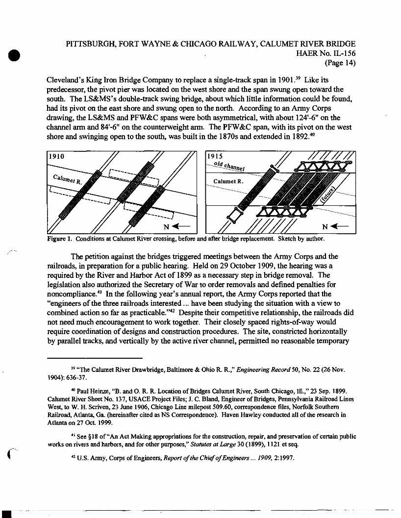
One early target of Calumet improvements was the trio of railroad bridges near 95th Street. They had previously escaped the Army Corps' notice: Colonel O. H. Ernst, who surveyed the river in 1904, found conditions acceptable from the mouth to 106th Street.37 But with a growing awareness of the Calumet's future, navigation interests submitted a petition for their replacement in April 1908. According to the following year's Army Corps annual report, complaints continued because "These bridges are of the center-pier type; they are placed very close together, and cross the stream at an angle, so that a vessel going up or down the river, when reaching these bridges, is obliged to make a sharp S curve in order to get safely through."38 The extant double-track swing bridges were an uncoordinated effort, except that they were arranged of necessity to provide an 85'-0" channel and avoid hitting each other when turning (see Figure 1). The B&OCT's bridge was 255'-0" long, symmetrical about its pivot, and built by
C
34 Liljencrantz, "Obstructive Bridges and Docks," 1092; quote from ibid., 1072.
35 Samuel M. Rowe, discussion following Liljencrantz, "Obstructive Bridges and Docks," 1095.
36 See "Report of Chicago Harbor Commission " Railway and Engineering Review 49, No. 12 (20 Mar. 1909): 275; George C. Sikes, "Report to the Chicago Harbor Commission on Obstacles to Chicago's Water Shipping Development," Marine Review 39, No. 4 (28 Jan. 1909): 30.
37 U.S. Army, Corps of Engineers, Annual Report... for the Year 1904 (Washington, D.C.: U.S. Government Printing Office, 1905), 3:2943.
38 U.S. Army, Corps of Engineers, Report of the Chief of Engineers, U.S. Army, 1908 (Washington, D.C.: U.S. Government Printing Office, 1909), 2:1996; ibid., Report of the Chief of Engineers... 1909 (Washington, D.C. U.S. Government Printing Office, 1910), 2:1997. The latter refers to "three railroad bridges near One hundred and sixth street," which are undeniably those near 95th Street.
PITTSBURGH, FORT WAYNE & CHICAGO RAILWAY, CALUMET RIVER BRIDGE HAERNo.IL-156
(Page 14)
Cleveland's King Iron Bridge Company to replace a single-track span in 1901.39 Like its predecessor, the pivot pier was located on the west shore and the span swung open toward the south. The LS&MS's double-track swing bridge, about which little information could be found, had its pivot on the east shore and swung open to the north. According to an Army Corps drawing, the LS&MS and PFW&C spans were both asymmetrical, with about 124'-6" on the channel arm and 84'-6" on the counterweight arm. The PFW&C span, with its pivot on the west shore and swinging open to the south, was built in the 1870s and extended in 1892.40
1910 //
"""""""*■■—-— jme '"—--
JMSr // '
K<
1915
---^-SSBSHW
////////
Catumet
/X //////// N<
Figure 1. Conditions at Calumet River crossing, before and after bridge replacement. Sketch by author.
The petition against the bridges triggered meetings between the Army Corps and the railroads, in preparation for a public hearing. Held on 29 October 1909, the hearing was a required by the River and Harbor Act of 1899 as a necessary step in bridge removal. The legislation also authorized the Secretary of War to order removals and defined penalties for noncompliance.41 In the following year's annual report, the Army Corps reported that the "engineers of the three railroads interested... have been studying the situation with a view to combined action so far as practicable."42 Despite their competitive relationship, the railroads did not need much encouragement to work together. Their closely spaced rights-of-way would require coordination of designs and construction procedures. The site, constricted horizontally by parallel tracks, and vertically by the active river channel, permitted no reasonable temporary
f
39 "The Calumet River Drawbridge, Baltimore & Ohio R. R.," Engineering Record 50, No. 22 (26 Nov. 1904): 636-37.
40 Paul Heinze, "B. and O. R. R. Location of Bridges Calumet River, South Chicago, 111.," 23 Sep. 1899. Calumet River Sheet No. 137, USACE Project Files; J. C. Bland, Engineer of Bridges, Pennsylvania Railroad Lines West, to W. H. Scriven, 23 June 1906, Chicago Line milepost 509.60, correspondence files, Norfolk Southern Railroad, Atlanta, Ga. (hereinafter cited as NS Correspondence). Haven Hawley conducted all of the research in Atlanta on 27 Oct. 1999.
41 See § 18 of "An Act Making appropriations for the construction, repair, and preservation of certain public works on rivers and harbors, and for other purposes," Statutes at Large 30 (1899), 1121 et seq.
42 U.S. Army, Corps of Engineers, Report of the Chief of Engineers... 1909, 2:1997.
PITTSBURGH, FORT WAYNE & CHICAGO RAILWAY, CALUMET RIVER BRIDGE HAERNo.IL-156
(Page 15)
crossing. In order to maintain traffic, the railroads would have to stagger construction and use each others' tracks. Crossing the East Chicago Canal at Indiana Harbor, these same constraints resulted in identical Rail-patent bascule bridges for all three lines, completed in 1909.43 The solution at South Chicago, however, was not so simple or straightforward.
Changing Plans
Only three of the five bridges existing at the Calumet River crossing in 1915 remain today, but their foundations alone tell a story of changing plans and disagreement among the railroads. Drawings found in the Army Corps' project files suggest at least two schemes sanctioned by the Chicago District, and the railroads themselves considered several others. Because the Army Corps was fundamentally unconcerned with the type of movable bridge built, provided that it met specifications of clearance and operating time, each railroad was free to select among several patented designs or to devise one of its own. During the three years between petition for removal and permission for replacement, the fledgling vertical-lift type evolved toward its mature form and gained acceptance in the engineering community. The PFW&C willingly embraced the new technology, but research suggests that the LS&MS was reluctant, and the B&OCT completely unwilling, to use it. The eventual result was four double- track vertical-lift bridges, one pair for the PFW&C and another pair immediately adjacent for the LS&MS, with a double-track Strauss bascule for the B&OCT some distance away. Although the LS&MS's bridges are similar to, and share foundations with, the PFW&C's, documentary and physical evidence indicate that construction began on a plan different from the one completed.
Vertical-lift bridges received little to no mention during negotiations with the Army Corps of Engineers, which concentrated on bascule designs instead. The omission is not surprising, however, considering that the only vertical-lift bridge then completed, designed by J. A. L. Waddell at South Halsted Street in Chicago (1893), had a reputation for difficult and expensive operation. Many sources credit John Lyle Harrington, Waddell's partner after 1907, with the mechanical refinements that made the vertical-lift bridge practicable. As proof of this fact, four Waddell and Harrington vertical-lift spans were under construction by October 1909.44
This seems to have had little influence on the railroads' meetings with the Army Corps, however. It was not until mid-1910, when the first four vertical-lift spans were at or near completion, that this type appeared as an option for South Chicago. The Army Corps' report for that fiscal year described two schemes for the Calumet River crossing on the table: "bridges of the bascule or vertical lift type providing either a clear channel of not less than 140 feet in width with head room of 16.5 feet, or two parallel channels of 90 feet clear width separated by a center rest pier
r 43 Joseph B. Strauss, "The Bascule Bridge in Chicago," in A Half-Century of Chicago Building, edited by
John H. Jones and Fred A. Britten (Chicago: 1910), 92.
44 See also Judith A. McGaw, "Hawthorne Bridge," HAER No. OR-20.
PITTSBURGH, FORT WAYNE & CHICAGO RAILWAY, CALUMET RIVER BRIDGE HAERNo.IL-156
(Page 16)
not more than 20 feet wide." Not mentioning the specifics of the debate, the report stated simply, "No agreement has as yet been reached as to which plan will be adopted."45
The first scheme proposed by the Army Corps actually predates the public hearing on bridge replacement. At some time during 1908, Colonel W. H. Bixby endorsed a plan showing a single, 120'-0" clear channel spanned by eight double-track bridges, clearly reflecting the railroads' hopes for increased traffic, as only six tracks existed at that time. The plan shows three PFW&C bridges, three LS&MS bridges, all equally spaced, single bascule leaves operating from the east shore. Two similar spans for the B&OCT are spaced at greater intervals, with one span operating from the west shore. Although the number of tracks may have matched the railroads' traffic projections, Bixby's scheme was ambitious in terms of span length. With the extreme 50- degree skew, a 120'-0" clear channel with clearances for pier protection would have required single-leaf "bascule bridges of about 225 feet length between bearings," as stated in the drawing's title.46 Waddell, in De Pontibus, stated that bascules were effective up to about 75'-0" leaves, "but beyond that limit the first cost of the structure begins to get too high as compared with another type of equally satisfactory structure, viz., the lift-bridge."47 This advice was biased in favor of Waddell's patented design, of course, but confirms that the Army Corps' plan was pushing the limits of available technology. When the B&OCT eventually completed a Strauss bascule bridge in 1913, its 230'-0"-Iong single leaf broke a world record.48 With obvious skepticism, the railroads' chief engineers tentatively agreed to a 120'-0" channel at a private meeting with Army Corps Major Thomas H. Rees on 21 October 1909, eight days before the public hearing.49
At the public hearing, the 120'-0" channel proved inadequate to meet navigation interests' demands, giving rise to the two-channel scheme as a compromise. According to the railroads' internal correspondence, the hearing was attended by representatives from shipping companies and "industries along 10 miles of frontage on the river," along with bascule bridge designer Joseph B. Strauss and a representative from the Strobel Steel Construction Company, which held
C
45 U.S. Army, Coips of Engineers, Report of the Chief of Engineers... 1910 (Washington, D.C.: U.S. Government Printing Office, 1911), 2:2154.
46 "Suggestions (1908) for New Draw Spans of 120 Feet Clear Width, and Bascule Bridges of about 225 Feet Length Between Bearings, for R. R. Crossings over Calumet River Near 97th Street, Chicago, 111." Calumet River Sheet No. 235, USACE Project Files.
47 J. A. L. Waddell, De Pontibus: A Pocket-Bookfor Bridge Engineers, 1st ed. (New York: John Wiley & Sons, 1898), 105.
48 See Appendix C for a list of sources on this bridge. In a telephone conversation with the author on 16 June 1999, Crew Heimer, an engineer with R. L. Banks and Associates, reported that a ship collided with and destroyed the B&OCT span ten or fifteen years ago. Limitations in the scope of this project prevented further investigation.
49 E. G. Ericson, Principal Assistant Engineer, to R. Trimble, Chief Engineer Maintenance of Way, Pennsylvania Lines West, 28 Oct. 1909, in NS Correspondence.
PITTSBURGH, FORT WAYNE & CHICAGO RAILWAY, CALUMET RIVER BRIDGE HAERNo.IL-156
(Page 17)
the late William Scherzer's bascule bridge patent.50 Desired channel widths ranged from 150'-0" to 300'-0", the latter coming from proponents of the Sag Channel widening. Rees settled for a single 140'-0" channel, which the railroads felt could not be spanned by a single leaf. With characteristic bravado, Strauss announced that he could design a bascule bridge spanning 140'-0" with double leaves locked together where they met at mid-span. The railroads' view was more in line with the Strobel representative's, however. He stated that such a connection would not be rigid enough to carry trains at full speed, so a mid-channel pier would be needed. The resulting scheme, found in Army Corps project files, is less neatly drawn over an existing survey, with handwriting similar to that found on Bixby's earlier proposal. It shows a "proposed center rest pier" 20'-0" wide, pierced by underwater openings, with 9O'-0" channels on either side.51 The drawing does not show a particular number of new bridges, but the pier's 410'-0" length would have accommodated eight double-track spans. Despite the emergence of this alternate scheme, one conclusion of the hearing was certain: that the existing bridges would have to be replaced. The Secretary of War ordered the railroads to replace their swing bridges on 28 January 1910.
The emergence of the vertical-lift option can be attributed to a change in leadership at the Army Corps' Chicago District. At the end of fiscal year 1910, Rees was replaced by Lieutenant Colonel George A. Zinn, in whose hands approval of the railroads' plans now rested. He was firmly behind the 140'-0" channel and just as firmly opposed to the two-channel scheme.52
Meanwhile, the national engineering press was reporting on several more vertical-lift bridges under construction elsewhere, including Kansas City's Armour-Swift-Burlington (ASB) Bridge and Portland's Steel Bridge (also known as the Harriman Bridge after the Union Pacific Railroad president). That the longest of Waddell and Harrington's early vertical-lift spans carried railroad traffic reflects railroad engineers' growing confidence in the type.53 A number of geometric advantages made the vertical-lift type particularly suitable for the Calumet River crossing. Whereas the existing swing bridges limited the number of tracks within each railroad's right-of- way, parallel vertical-lift spans could be built with a minimum of horizontal clearance between them. This was also true of the bascule type, but unlike the bascule, the vertical-lift could accommodate extreme skews and allow shorter vessels through with a partial lift.54 Not entirely
C
so Ericson, to Trimble, 28 Oct. 1909.
51 "Sketch Plan Showing Proposed Location of Two Channels — 90 Ft. Clear Width with Center Rest Pier," 5 Dec. 1909, Calumet River Sheet No. 244, USACE Project Files.
52 D. M. Craig, Track Elevation Engineer, to Trimble, 2 Mar. 1911, in NS Correspondence. The Army Corps' policy on mid-channel obstructions had been articulated as early as 1890; see U.S. Army, Corps of Engineers, Annual Report ...for the Year 1900 (Washington, D.C.: U.S. Government Printing Office, 1901), 5:3869.
53 Appendix A, based on Waddell's "nearly ... chronological" list of vertical-lift bridges, is the basis for speculation on the order of their construction in this report.
54 There are many sources stating the advantages of the vertical-lift type, but this particular list was culled from Otis E. Hovey, Movable Bridges, 2 vols. (New York: John Wiley & Sons, 1926), 1:25.
PITTSBURGH, FORT WAYNE & CHICAGO RAILWAY, CALUMET RIVER BRIDGE HAERNo.IL-156
(Page 18)
sure that a bascule span could meet their needs at South Chicago, the B&OCT, LS&MS, and PFW&C began to consider this emerging technology.
Although the Army Corps' clearance requirements were inflexible, the railroads had considerable latitude in adjusting the number, spacing, and type of bridges. The three railroads' chief engineers evidently agreed, at least temporarily, to build vertical-lift bridges. Their signatures appear together on a January 1911 drawing showing (from south to north) two double- track spans for the PFW&C, a four-track bridge for the LS&MS with future expansion on a parallel double-track span, followed by two double-track spans for the B&OCT.55 It is unclear why the B&OCT chose to build a Strauss bascule bridge instead, but the Secretary of War issued a permit for its construction on 13 May 1911. Four days later, the LS&MS and PFW&C received permits to construct vertical-lift bridges.56
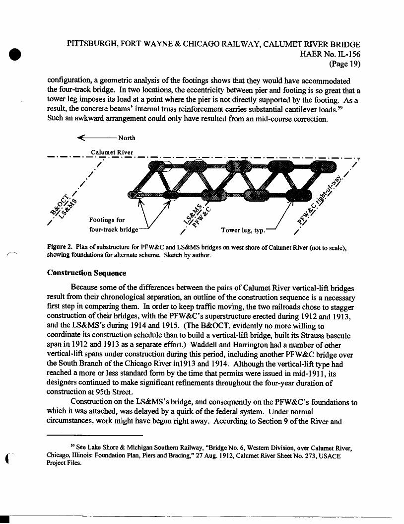
The LS&MS evidently began pouring foundations for what would have been the world's first four-track vertical-lift bridge, then decided against it. As Waddell later explained to the second Pan American Scientific Congress, "At first the Lake Shore & Michigan Southern Co. intended to build a four-track lift span, and the plans were prepared accordingly; but later they decided to follow the lead of the Pennsylvania Railroad Co. and build two bridges close together, the object being to provide for a possible breakdown."57 (This did not mean that the LS&MS would build exact duplicates of the PFW&C's bridges; the two railroads' structural specifications were different enough that two sets of plans were still needed.) Although an exact date could not be found, descriptions of the four-track scheme appeared in engineering periodicals as late as July 1912, and erection of the two-track superstructures did not begin until late 1913.58 Furthermore, physical evidence at the site suggests that the four-track scheme was abandoned after foundation work had begun. On the east shore of the river, the reinforced concrete substructure matches the as-built configuration of four two-track bridges, two for each railroad, with room for an additional two-track span on either side. Oval piers, tied together by reinforced concrete beams, sit concentrically atop reinforced concrete footings extending down to bedrock. On the west shore, however, the piers supporting the LS&MS bridges have a different configuration than the footings below (see Figure 2). While the piers match the as-built
55 Lake Shore & Michigan Southern Railway Bridge Department, "Proposed Bridge No. 6 Western Div. over Calumet River, South Chicago, 111., Location Plan," Drawing No. B-4046-R1 (16 Jan. 1911), Calumet River Sheet No. 273, USACE Project Files. This arrangement is identical to ibid., "Proposed Four Track Lift Bridge across Calumet River, South Chicago, 111., Survey from U.S. Government Map of 1900," Drawing No. B-4120 (7 Apr. 1911), Calumet River Sheet No. 271, USACE Project Files.
56 U.S. Army, Corps of Engineers, Report of the Chief of Engineers... 1912 (Washington, D.C.: U.S. Government Printing Office, 1913), 2:2547. Note that the B&OCT "swing bridge" mentioned by Zinn is a misnomer for the Strauss bascule bridge then completed. This same error occurs in ibid., Report of the Chief of Engineers... 1913 (Washington, D.C.: U.S. Government Printing Office, 1914), 2:2811.
57 Waddell, "Vertical Lift Bridges," 6:177.
58 "Calumet River Drawbridge Substructure," Engineering Record 66, No. 4 (27 July 1912): 94.
PITTSBURGH, FORT WAYNE & CHICAGO RAILWAY, CALUMET RIVER BRIDGE HAERNo.IL-156
(Page 19)
configuration, a geometric analysis of the footings shows that they would have accommodated the four-track bridge. In two locations, the eccentricity between pier and footing is so great that a tower leg imposes its load at a point where the pier is not directly supported by the footing. As a result, the concrete beams' internal truss reinforcement carries substantial cantilever loads.59
Such an awkward arrangement could only have resulted from an mid-course correction.
North
Calumet River
/ /
/
/ Footings for four-track bridge
Figure 2. Plan of substructure for PFW&C and LS&MS bridges on west shore of Calumet River (not to scale), showing foundations for alternate scheme. Sketch by author.
Construction Sequence
Because some of the differences between the pairs of Calumet River vertical-lift bridges result from their chronological separation, an outline of the construction sequence is a necessary first step in comparing them. In order to keep traffic moving, the two railroads chose to stagger construction of their bridges, with the PFW&C s superstructure erected during 1912 and 1913, and the LS&MS's during 1914 and 1915. (The B&OCT, evidently no more willing to coordinate its construction schedule than to build a vertical-lift bridge, built its Strauss bascule span in 1912 and 1913 as a separate effort.) Waddell and Harrington had a number of other vertical-lift spans under construction during this period, including another PFW&C bridge over the South Branch of the Chicago River inl913 and 1914. Although the vertical-lift type had reached a more or less standard form by the time that permits were issued in mid-1911, its designers continued to make significant refinements throughout the four-year duration of construction at 95th Street.
Construction on the LS&MS's bridge, and consequently on the PFW&C's foundations to which it was attached, was delayed by a quirk of the federal system. Under normal circumstances, work might have begun right away. According to Section 9 of the River and
59 See Lake Shore & Michigan Southern Railway, "Bridge No. 6, Western Division, over Calumet River, Chicago, Illinois: Foundation Plan, Piers and Bracing," 27 Aug. 1912, Calumet River Sheet No. 273, USACE Project Files.
PITTSBURGH, FORT WAYNE & CHICAGO RAILWAY, CALUMET RIVER BRIDGE HAERNo.IL-156
(Page 20)
Harbor Act of 1899, once the Secretary of War had approved plans for a bridge crossing a navigable waterway "wholly within the limits of a single State," it could be built under state authority without special permission from Congress. In Illinois, an 1872 law giving blanket consent presented no obstacle at the state level.60 It is therefore surprising that the LS&MS's permit from the War Department was contingent upon Congressional approval, while permits for the adjacent bridges on either side had no such condition. One possible explanation is that the LS&MS's bridge constituted part of a mail route. As explained by postal historian Richard R. John, "Federal officials throughout the nineteenth and early twentieth centuries took it for granted that rights-of-way on which the mails were carried had a federal character — regardless of who built or maintained the right-of-way itself."61 Indeed, the LS&MS ran a Railway Post Office car on its Buffalo-to-Chicago route in 1911, whereas the PFW&C evidently carried no mail at all.62 House and Senate commerce committee reports provide no explanation, indicating only their recommendation that construction of the LS&MS's bridge be authorized by Congress. The minimum of discussion indicates that this step simply may have been a formality. The bill passed and was signed by the President in February 1912, clearing the last legislative obstacle.63
Work on the Calumet River bridges did not wait for Congress' approval, however. Drawings for both railroads' bridges date back to mid-1911, and preparatory work such as the construction of detour tracks was likely also under way. The LS&MS's existing swing bridge was wider and stronger, so it was chosen to carry both railroads' traffic while the PFW&C demolished its swing bridge to make way for new vertical-lift structures. On 24 October 1911, the PFW&C awarded the substructure contract to the Dravo Contracting Company of Pittsburgh, which had been the successful bidder on many PRR projects back east.64 Usual practice was to incorporate transportation of equipment and materials into the contract, allowing a company to
60 See Statutes at Large 30 (1899), 1151; Laws of Illinois (1871-72), 209.
C
61 The author is grateful to Haven Hawley for inspiring this line of investigation. Quote from Richard R. John, Associate Professor of History at University of Illinois at Chicago, e-mail to author, 11 Dec. 2000.
62 U.S. Congress, House, Committee on the Post Office and Post Roads, Letter from the Postmaster General Submitting a Report Giving the Results of the Inquiry as to the Operation, Receipts, and Expenditures of the Railroad Companies Transporting the Mails, and Recommending Legislation on the Subject, 62nd Cong., 1 st sess., 1911, H. Doc. 105,262. The PFW&C is not mentioned in the list of PRR subsidiaries carrying mail; see ibid., 50-53.
63 U.S. Congress, House, Committee on Interstate and Foreign Commerce, Bascule Bridge Across Calumet River, Chicago, 62nd Cong., 2nd sess., 1912, H. Rept. 284; Senate, Committee on Commerce, Bridge Across the Calumet River, South Chicago, III, 62nd Cong., 2nd sess., 1912, S. Rept. 335; Congressional Record48 (14 Feb. 1912): 2046. That both bills mention a bascule bridge is probably an artifact of the earlier proposals.
64 Waddell and Harrington, Consulting Engineers, "Bridge No. 443 over the Calumet River, Chicago, 111., Pennsylvania Lines West of Pittsburgh, Chicago Terminal Division, N. W. System: General Data," 1 Apr. 1914, Chicago Line milepost 509.60, aperture card files, Norfolk Southern Railroad, Atlanta, Ga. (hereinafter cited as NS Aperture Cards).
PITTSBURGH, FORT WAYNE & CHICAGO RAILWAY, CALUMET RIVER BRIDGE HAERNo.IL-156
(Page 21)
bid on jobs wherever the railroad went. Given the monolithic nature of the LS&MS and PFW&C bridges' foundations, it is almost certain that they were built as a single effort completed in November 1912. It is conceivable that foundation work could have proceeded around the LS&MS swing bridge, the counterweight arm of which interfered with only one pier of the new vertical-lift spans. This theory is consistent with dates on the LS&MS's foundation drawings, 9 September 1911 for the four-track scheme and 27 August 1912 for the two-track scheme.65 Even with the mid-course correction, it seems possible that Dravo could have completed all substructure work before the December 1912 start of erection on the PFW&C superstructure.
Meanwhile, Waddell and Harrington had completed plans for the PFW&C superstructure so that fabrication work would be completed in advance of erection. The fabrication contract went to another familiar name in PRR projects: the Pennsylvania Steel Company of Steelton, Pennsylvania. According to steel historian Thomas J. Misa, the company was a "captive steel plant," sharing many executives with the PRR as an example of the railroad's efforts at vertical integration. From its "otherwise disadvantageous location on the road's main line through Harrisburg," Pennsylvania Steel shipped rails and structural steel throughout the PRR network.66
At times, the company even outbid independent firms to erect the steel that it supplied, for example with the PFW&C's Chicago River bridge.67 For the PFW&C's Calumet River bridges, however, Pennsylvania Steel could not compete with local firms. On 24 May 1912, the Kelly- Atkinson Company of Chicago was awarded the erection contract.68 The company spent several months developing an erection plan, and began work on 10 December of that year.
The erection of the PFW&C bridges is described in a short article by W. J. Howard, an engineer with Kelly-Atkinson.69 Towers were erected first, then used to support falsework so that the movable truss spans could be built in their raised position, without interfering with river traffic. Work began on the east shore, using a 30-ton derrick with a 70-foot steel boom to erect the tower for the north span. This piece of equipment, designed by Kelly-Atkinson engineers and fabricated by the American Bridge Company of Chicago, garnered a separate article in
C
65 LS&MS, Bridge Department, "Foundation Plan, Piers and Bracing."
66 Thomas J. Misa, A Nation of Steel: The Making of Modern America, 1865-1925 (Baltimore: Johns Hopkins Univ. Press, 1995), 21-22. For contemporary descriptions of the Steelton shops, see "A Model Bridge and Construction Shop," Iron Age 72 (10 Sep. 1903): 1-7; or "The Pennsylvania Steel Company's Model Bridge Plant," Engineering Record48, No. 13 (26 Sep. 1903): 360-63, No. 14 (3 Oct. 1903): 395-99, No. 15 (10 Oct. 1903): 423- 26, No. 16 (17 Oct. 1903): 455-58, and No. 17 (24 Oct. 1903): 494-96. An overview history is provided by David Jackson, "Pennsylvania Steel, 1867-1916," Keystone 31, No. 4 (Winter 1998): 41-50.
67 See sources cited in Frances Alexander et al., "Pennsylvania Railroad, South Branch Chicago River Bridge," HAERNo. IL-112.
68 Waddell and Harrington, "Bridge No. 443 ... General Data."
69 W.J.Howard, "Erection ofa Cable Lift Bridge," Engineering News 70, No. 11 (11 Sep. 1913).
PITTSBURGH, FORT WAYNE & CHICAGO RAILWAY, CALUMET RIVER BRIDGE HAERNo.IL-156
(Page 22)
Engineering News.70 Once the north tower was complete, the south tower and falsework on the east shore were erected using a different derrick. It had a 68-foot wooden boom and used a tower leg for its mast. Meanwhile, the 70-foot steel derrick was moved to the west shore and used to erect the north tower there. Falsework on the east shore rested on a line of piles driven into the riverbed parallel to the existing 85'-0" channel and restricting its width by about 5 feet.71 From this line of piles, 103'-0"-long girders extended back toward the towers, creating a platform 40'-0" above the river's surface, under which the LS&MS's swing bridge turned. Heavy timber scaffolding was built on this platform to support the easternmost three panels of the movable truss spans. On the west shore, timber bents leaned outward from the abutment, forming a knee brace to support the western end of the movable truss spans. While the falsework was going up, the counterweights were cast in their lowered positions. The counterweights on the west end were raised and used to help support the lower chord of the truss during erection, via cables slung over the sheaves to the third panel point. This left only the two middle panels of each truss without direct support. The gaps were closed with 30-ton lower-chord sections lifted into place by a derrick on the east-shore falsework. Once the movable truss spans were complete, crews returned the west counterweights to their lowered positions, installed the span-to-counterweight cables, and prepared the bridges for operation in mid-September 1913.
Although the PFW&C's bridges received some attention from the engineering press, the vertical-lift type was becoming increasingly common and the LS&MS's received no coverage at all. Because the builder's plates have been removed from the LS&MS spans, it is difficult to determine whether they were fabricated and erected by the same firms responsible for the PFW&C spans.72 In any case, erection of the LS&MS's bridges could not have begun until the PFW&C spans were completed, traffic rerouted, and the old swing bridge demolished. Reporting on the adjacent B&OCT bridge in 20 December 1913, Engineering Record noted that the new bascule span had yet to be put into service because it interfered with the LS&MS's swing bridge.73 It is therefore unlikely that erection on the LS&MS's vertical-lift bridges began before 1914. That the Army Corps extended the deadline for completion no further than 31 December 1915 indicates that they were finished that year.74 During the course of erection, two major changes occurred: the LS&MS was absorbed into the NYC, and the seven-year-old partnership of Waddell and Harrington dissolved. Construction nonetheless proceeded to
C
70 "Steel Guyed Derrick for Bridge Erection," Engineering News 71, No. 24 (11 June 1914): 1307-08.
71 Kelly-Atkinson Construction Co., "Location Diagram: Pile Plan for False Work, Bridge #443, Perm. Ry. Co., So. Chicago, 111.," July 1912, Calumet River Sheet No. 273, USACE Project Files.
72 It is worth noting mat Pennsylvania Steel fabricated and erected the adjacent B&OCT bridge; see "Largest Bascule Bridge " 697.
73 "Largest Bascule Bridge," 697.
74 U.S. Army, Corps of Engineers, Report of the Chief of Engineers... 1914 (Washington, D.C.: U.S. Government Printing Office, 1915), 2:2932.
PITTSBURGH, FORT WAYNE & CHICAGO RAILWAY, CALUMET RIVER BRIDGE HAERNo.IL-156
(Page 23)
completion, leaving the four vertical-lift bridges over the Calumet River as a monument to both engineers.
Waddell and Harrington
John Alexander Low (J. A. L.) Waddell is widely known as the progenitor of large-scale vertical-lift bridges, mostly because of his prolific and "somewhat autobiographical" writings. Waddell was a terrific self-promoter, and his actual engineering work was often a secondary concern. As engineering historian Henry Petroski remarked, "Waddell seems to have paid considerably more attention to photographs of himself," with ever-increasing numbers of medals pinned to his chest, "than to those of his bridges."75 Although Waddell was undoubtedly the first to apply the vertical-lift concept to long spans, it seems that Harrington introduced many of the refinements that made the design commercially viable. As Petroski and others have suggested, Waddell may have spent more of his time writing than engineering.
A variety of sources state the facts of Waddell's life. The title page of his book Bridge Engineering condenses seven degrees and thirty-five memberships into trapezoids of small type. Harrington prefaced his then-mentor's Principal Professional Papers (1905) with a flattering biography, including a two-page section on "Engineering and Fishing" no doubt intended to present the Pontifex Maximus in a humbler light. Successors to Waddell's engineering practice, such as Howard, Needles, Tammen, and Bergendoff (HNTB), repeat the biographical details in their company histories. Rather than re-state the details of Waddell's 1854 birth in Port Hope, Ontario, and the "delicate health" of his youth, this report shall refer the reader to those sources.76
It is worth mentioning here, however, that after experience in surveying for railroads and mines, teaching, designing bridges, and supervising their construction, Waddell settled down in Kansas City, Missouri. There he served as a Phoenix Bridge Company agent and set up an engineering consulting firm. The latter enterprise attracted Harrington as an employee during the summers of his education at the University of Kansas in the early 1890s. During this time Waddell built his first long-span vertical-lift bridge, but the second had to wait until after the partnership of Waddell and Harrington was formed in 1907.
Biographers make it clear that without Harrington's contributions, Waddell would have had only one vertical-lift bridge to write about. Waddell deserves credit for the idea of applying the vertical-lift idea to long spans, but it seems that he lacked the mechanical engineering skills to make it work properly. As noted by historian of technology Edwin Layton,
f
75 Henry Petroski, Engineers of Dreams: Great Bridge Builders and the Spanning of America (New York: Alfred A. Knopf, 1995), 199.
76 Quote from John L. Harrington, ed., The Principal Professional Papers of Dr. J. A. L. Waddell, Civil Engineer, 1 st ed. (New York: Virgil H. Hewes, 1905), 1; see also Kathi A. Brown, Diversity by Design: Celebrating 75 Years of Howard Needles Tammen & Bergendoff, 1914-1989, 1st ed. (Kansas City, Mo.: Lowell Press, 1989).
PITTSBURGH, FORT WAYNE & CHICAGO RAILWAY, CALUMET RIVER BRIDGE HAERNo.IL-156
(Page 24)
Waddell's bridge was poorly designed in its mechanical engineering features: he used unbushed, cast-iron bearings, cast-iron gears with moulded [sic] teeth, and other deficient equipment.... Waddell's design had only a poor connection between the machinery and the structural supports, inadequate brakes, and a lack of adequate signaling and safety features. Harrington corrected all of these....77
Waddell's writing seems to reflect a lack of interest in such features. Although Waddell listed and classified a good many vertical-lift bridges in his two-volume text Bridge Engineering, he did not provide specific information or equations for design, citing a forthcoming work by Harrington.78 To this author's knowledge, Harrington never authored a book on vertical-lift bridge design. Waddell's remark may simply have been a jab at Harrington, who had fewer published writings than Waddell and had refused co-authorship of Bridge Engineering.79 After Waddell and Harrington split up in December 1913, both continued to design vertical-lift bridges. Only Harrington continued to patent new features, however, suggesting that he may have been the more innovative of the two partners. Regardless, Harrington's role in the vertical- lift bridge's development became a point of contention between them. Waddell's egotistical viewpoint is typified by a 1918 statement that he "may justly claim to be the father of the modern vertical-lift bridge."80 If so, he was not an attentive parent. According to former employee Frank M. Cortelyou, Sr., Waddell had "little interest in the day to day work of the firm." Harrington and Ernest E. Howard, who also left the firm to become Harrington's partner, deserve more credit than Waddell gave them.81 To use Waddell's metaphor, Harrington and Howard were foster parents, responsible for raising someone else's vertical-lift bridge design to maturity.
In contrast to Waddell's primarily civil engineering background, Harrington seems to have excelled at mechanical engineering as well. He was born in Lawrence, Kansas, in 1868, making him fourteen years Waddell's junior. He graduated from the University of Kansas in 1895, with several degrees including civil engineering. The university had admitted him by examination because, having grown up on a farm, he had little formal education. He worked for Waddell during college and for nine months afterward. Harrington then seems to have followed Waddell's advice that engineering students begin their careers with a variety of work.82 From
C
77 Edwin Layton, letter to Frank M. Cortelyou, Sr., 5 Nov. 1969, in John L. Harrington Material, MG 2731, Western Historical Manuscript Collection, Ellis Library, University of Missouri, Columbia, Mo. (hereinafter cited as Harrington Material).
78 J. A. L. Waddell, Bridge Engineering, 2 vols. (New York: John Wiley & Sons, 1916), 1:664,717.
79 Frank M. Cortelyou, Sr., letter to Edwin Layton, 8 July 1969, in Harrington Material.
80 J. A. L. Waddell, discussion following Horatio P. van Cleve, "The Mechanical Features of the Vertical Lift Bridge," Transactions of the American Society of Mechanical Engineers 40 (1918): 1035.
81 Frank M. Cortelyou, Sr., letter to Edwin Layton, 11 Sep. 1969, in Harrington Material.
82 Harrington, The Principal Professional Papers of Dr. J. A. L. Waddell.
PITTSBURGH, FORT WAYNE & CHICAGO RAILWAY, CALUMET RIVER BRIDGE HAERNo.IL-156
(Page 25)
1896 to 1899, he took a series of jobs with bridge fabricators in Pennsylvania and New York. One wonders what Harrington thought of his mentor's South Halsted Street Bridge, which he must have seen during an 1899 stint with the Northwestern Elevated Railroad in Chicago. His subsequent experience included more mechanically oriented firms such as the C. W. Hunt Company in New York and the Locomotive and Machine Company in Montreal. He preferred consulting, however, and joined Waddell's firm as a partner in 1907.83 After an "undisclosed controversy" with Waddell, Harrington took his skills — and Howard — to a partnership with Louis R. Ash, which lasted from 1914 until 1927.84 A subsequent firm founded by Harrington and Cortelyou in 1928 still exists today.
The Evolving Vertical-Lift Bridge
No two Waddell and Harrington vertical-lift spans, except parallel installations such as each pair of Calumet River bridges, are exactly alike in their details. Even in South Chicago, the LS&MS's pair of spans differ subtly from the PFW&C's, despite their identical span length and lift height. Details were changed in response to not only owner's specifications and site conditions, but also lessons learned from bridges already completed. With several bridges under construction concurrently, news could arrive mid-project, requiring design changes on the fly. Bolt failures in the Steel Bridge's main sheaves, observed historian Judith McGaw, "functioned as an immediate learning experience for Waddell and Harrington; they quickly redesigned the built-up main sheaves on Pennsylvania Railroad bridges under construction in South Chicago."85
Even the PFW&C's Calumet River spans, under construction in 1912 and 1913, provided lessons for the adjacent pair of LS&MS spans (1914-15), as well as for the PFW&C's Chicago River bridge (1913-14). To study the full course of these changes, one must return to Waddell's first vertical-lift bridge.
The South Halsted Street Bridge in Chicago is sometimes mistakenly called the world's first vertical-lift bridge. It was, however, the first long span with a lift of significant height. As the engineer himself wrote, "Lift-bridges on a small scale have been used for many years for crossings of canals.... No large structure of this type was ever built until 1893."86 Writing about vertical-lift bridges in Bridge Engineering, Waddell summarized Henry G. Tyrrell's research into the history of the form, citing a 30'-0" span over the Danube as "the first one of which there is any record," then presenting a list of unbuilt proposals for lift spans up to 300'-0" in Europe. In
C
83 Frank M. Cortelyou et al., "Memoir of John Lyle Harrington," Transactions of the American Society of Civil Engineers 107(1942): 1768-69.
84 Brown, Diversity by Design.
85 Judith A. McGaw, "Steel Bridge," HAER No. OR-21.
86 For example, Albert Lucius' 104'-0"-long bridge over the Erie Canal at Syracuse (1882) lifted only 8'-0"; see J. A. L. Waddell, "The Halsted Street Lift-Bridge," Transactions of the American Society of Civil Engineers 33 (1895): 58. Quote from Waddell, De Pontibus, 108.
PITTSBURGH, FORT WAYNE & CHICAGO RAILWAY, CALUMET RIVER BRIDGE HAERNo.IL-156
(Page 26)
the U.S., the idea of a span translating vertically dates to the 1872 patent of Squire Whipple. This patent described a deck lifted by a series of chains from an overhead truss, and formed the basis for many such spans he designed over the Erie Canal.87 Waddell used the lifting-deck idea on later bridges, but his first designs have a truss span lifted at its ends rather than a deck lifted at intermediate points.
Although Chicago's South Halsted Street Bridge was the first Waddell vertical-lift span actually constructed, a proposal for a bridge over the Duluth Ship Canal should be considered as the true origin of his design. In fact, the South Halsted Street Bridge, as built, was in many aspects inferior to the unbuilt Duluth proposal. The latter appeared in the 8 April 1892 issue of Railroad Gazette, in sufficient detail for comparison with the Chicago bridges.88 Instead of a separate description of each bridge, the following sections will compare their skew angle, towers, movable spans, cables, counterweights, and other details, all of which had evolved in the three decades between the Duluth proposal and the Calumet River bridges. (Hereinafter "cable" is used to describe a functional component of the vertical-lift bridge, with the understanding that a cable may consist of one or more braided steel wire ropes.) Where appropriate, the discussion includes patents granted to Waddell, Harrington, and their partners; a comprehensive list of patents appears in Appendix B.
Suitability for Skew Crossings
The vertical-lift bridge is rare in its ability to accommodate skew crossings. Swing bridges, with their already obstructive mid-channel pivot piers, caused even more trouble where streets or railroads crossed the channel at an acute angle. Because bridge designers usually placed lines of pier protection parallel to the channel, any deviation from a perpendicular crossing further reduced the navigable width. Illustrations accompanying Liljencrantz's 1898 presentation on the Chicago River show numerous bridge abutments projecting beyond dock lines into river channels. Even Waddell's much-praised vertical-lift bridge at South Halsted Street presented an opening not parallel to the dock lines on either side. But as the Army Corps became more stringent in removing obstructions, projecting abutments were no longer an option. Geometry dictates that for a constant clear channel, the more acute the crossing angle, the longer the truss required. By skewing the ends of the span, however, the required length is reduced somewhat. Figure 3 shows a hypothetical situation, similar to the Calumet River crossing in South Chicago, where a railroad intersects a 140'-0" channel at a 50-degree angle. The trusses, placed 31'-0" apart for two tracks, can be as much as 26'-0" shorter for a skew configuration than for a square one, a substantial savings of material.
C
87 Squire Whipple, "Improvement in Lift Draw-Bridges," U.S. Patent No. 134,338,24 Dec. 1872.
88 "A Proposed Lift Bridge at Duluth, Minn.," Railroad Gazette 24, No. 15 (8 Apr. 1892): 259-60. The accompanying text contains many sentences also appearing, slightly modified, in Waddell, "The Halsted Street Lift- Bridge."
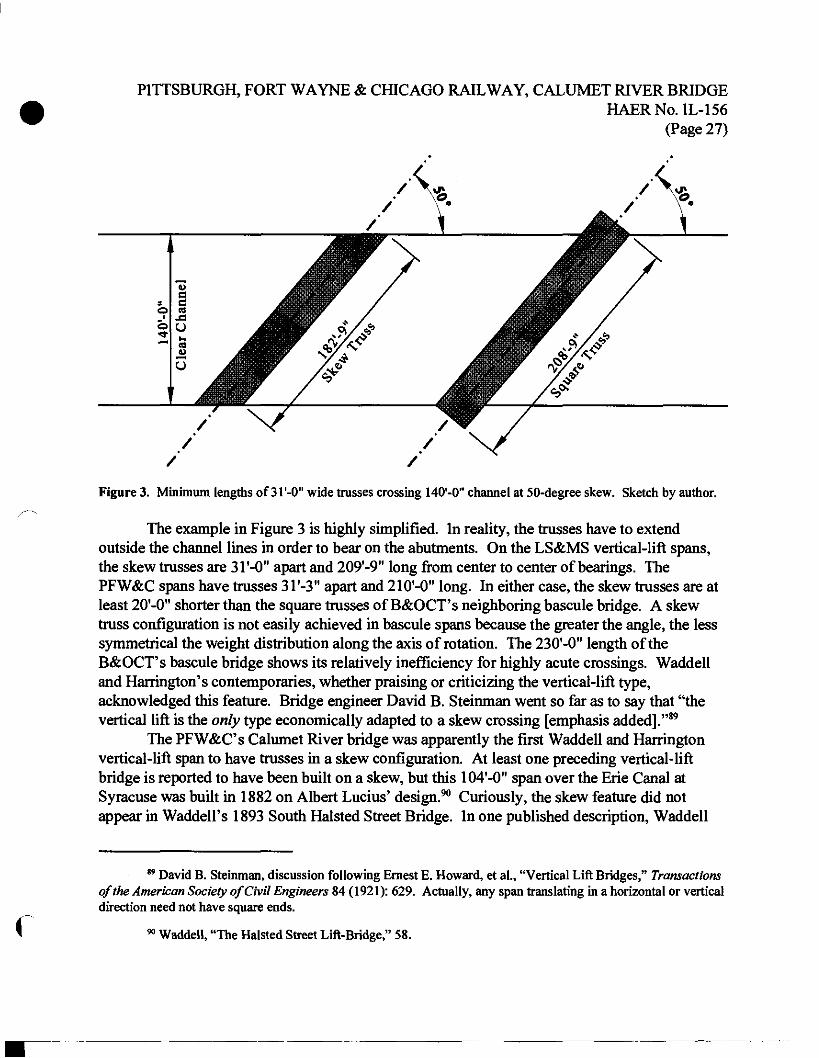
PITTSBURGH, FORT WAYNE & CHICAGO RAILWAY, CALUMET RIVER BRIDGE HAERNo.IL-156
(Page 27)
u a
b c3 J3
o C) ■<r
fr4
u o
1
/ /
Figure 3. Minimum lengths of 31'-0" wide trusses crossing 140'-0" channel at 50-degree skew. Sketch by author.
The example in Figure 3 is highly simplified. In reality, the trusses have to extend outside the channel lines in order to bear on the abutments. On the LS&MS vertical-lift spans, the skew trusses are 31'-0" apart and 209'-9" long from center to center of bearings. The PFW&C spans have trusses 3T-3" apart and 210'-0" long. In either case, the skew trusses are at least 20'-0" shorter than the square trusses of B&OCT's neighboring bascule bridge. A skew truss configuration is not easily achieved in bascule spans because the greater the angle, the less symmetrical the weight distribution along the axis of rotation. The 230'-0" length of the B&OCT's bascule bridge shows its relatively inefficiency for highly acute crossings. Waddell and Harrington's contemporaries, whether praising or criticizing the vertical-lift type, acknowledged this feature. Bridge engineer David B. Steinman went so far as to say that "the vertical lift is the only type economically adapted to a skew crossing [emphasis added]."89
The PFW&C's Calumet River bridge was apparently the first Waddell and Harrington vertical-lift span to have trusses in a skew configuration. At least one preceding vertical-lift bridge is reported to have been built on a skew, but this 104'-0" span over the Erie Canal at Syracuse was built in 1882 on Albert Lucius' design.90 Curiously, the skew feature did not appear in Waddell's 1893 South Halsted Street Bridge. In one published description, Waddell
f
89 David B. Steinman, discussion following Ernest E. Howard, et al., "Vertical Lift Bridges," Transactions of the American Society of Civil Engineers 84 (1921): 629. Actually, any span translating in a horizontal or vertical direction need not have square ends.
90 Waddell, "The Halsted Street Lift-Bridge," 58.
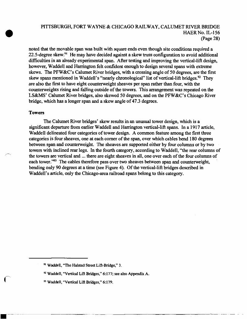
PITTSBURGH, FORT WAYNE & CHICAGO RAILWAY, CALUMET RIVER BRIDGE HAERNo.IL-156
(Page 28)
noted that the movable span was built with square ends even though site conditions required a 22.5-degree skew.91 He may have decided against a skew truss configuration to avoid additional difficulties in an already experimental span. After testing and improving the vertical-lift design, however, Waddell and Harrington felt confident enough to design several spans with extreme skews. The PFW&C's Calumet River bridges, with a crossing angle of 50 degrees, are the first skew spans mentioned in Waddell's "nearly chronological" list of vertical-lift bridges.92 They are also the first to have eight counterweight sheaves per span rather than four, with the counterweights rising and falling outside of the towers. This arrangement was repeated on the LS&MS* Calumet River bridges, also skewed 50 degrees, and on the PFW&C's Chicago River bridge, which has a longer span and a skew angle of 47.3 degrees.
Towers
The Calumet River bridges' skew results in an unusual tower design, which is a significant departure from earlier Waddell and Harrington vertical-lift spans. In a 1917 article, Waddell delineated four categories of tower design. A common feature among the first three categories is four sheaves, one at each corner of the span, over which cables bend 180 degrees between span and counterweight. The sheaves are supported either by four columns or by two towers with inclined rear legs. In the fourth category, according to Waddell, "the rear columns of the towers are vertical and ... there are eight sheaves in all, one over each of the four columns of each tower."93 The cables therefore pass over two sheaves between span and counterweight, bending only 90 degrees at a time (see Figure 4). Of the vertical-lift bridges described in Waddell's article, only the Chicago-area railroad spans belong to this category.
C
91 Waddell, "The Halsted Street Lift-Bridge," 3.
92 Waddell, "Vertical Lift Bridges," 6:177; see also Appendix A.
93 Waddell, "Vertical Lift Bridges," 6:179.
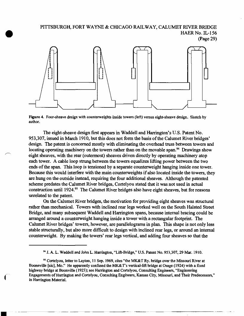
PITTSBURGH, FORT WAYNE & CHICAGO RAILWAY, CALUMET RIVER BRIDGE HAERNo.IL-156
(Page 29)
Figure 4. Four-sheave design with counterweights inside towers (left) versus eight-sheave design. Sketch by author.
The eight-sheave design first appears in Waddell and Harrington's U.S. Patent No. 953,307, issued in March 1910, but this does not form the basis of the Calumet River bridges' design. The patent is concerned mostly with eliminating the overhead truss between towers and locating operating machinery on the towers rather than on the movable span.94 Drawings show eight sheaves, with the rear (outermost) sheaves driven directly by operating machinery atop each tower. A cable loop strung between the towers equalizes lifting power between the two ends of the span. This loop is tensioned by a separate counterweight hanging inside one tower. Because this would interfere with the main counterweights if also located inside the towers, they are hung on the outside instead, requiring the four additional sheaves. Although the patented scheme predates the Calumet River bridges, Cortelyou stated that it was not used in actual construction until 1924.95 The Calumet River bridges also have eight sheaves, but for reasons unrelated to the patent.
On the Calumet River bridges, the motivation for providing eight sheaves was structural rather than mechanical. Towers with inclined rear legs worked well on the South Halsted Street Bridge, and many subsequent Waddell and Harrington spans, because internal bracing could be arranged around a counterweight hanging inside a tower with a rectangular footprint. The Calumet River bridges' towers, however, are parallelograms in plan. This shape is not only less stable structurally, but also more difficult to design with inclined rear legs, or around an internal counterweight. By making the towers' rear legs vertical, and adding four sheaves so that the
94 J. A. L. Waddell and John L. Harrington, "Lift-Bridge," U.S. Patent No. 953,307,29 Mar. 1910.
95 Cortelyou, letter to Layton, 11 Sep. 1969, cites "the MK&T Ry. bridge over the Missouri River at Booneville [sic], Mo." He apparently confused the MK&T's vertical-lift bridge at Osage (1924) with a fixed highway bridge at Boonville (1923); see Harrington and Cortelyou, Consulting Engineers, "Engineering Engagements of Harrington and Cortelyou, Consulting Engineers, Kansas City, Missouri, and Their Predecessors,' in Harrington Material.
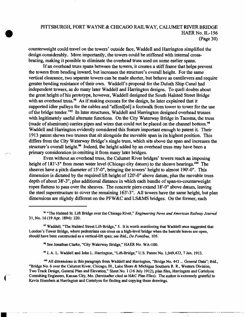
PITTSBURGH, FORT WAYNE & CHICAGO RAILWAY, CALUMET RIVER BRIDGE HAERNo.IL-156
(Page 30)
counterweight could travel on the towers' outside face, Waddell and Harrington simplified the design considerably. More importantly, the towers could be stiffened with internal cross- bracing, making it possible to eliminate the overhead truss used on some earlier spans.
If an overhead truss spans between the towers, it creates a stiff frame that helps prevent the towers from bending inward, but increases the structure's overall height. For the same vertical clearance, two separate towers can be made shorter, but behave as cantilevers and require greater bending resistance of their own. Waddell's proposal for the Duluth Ship Canal had independent towers, as do many later Waddell and Harrington designs. To quell doubts about the great height of his prototype, however, Waddell designed the South Halsted Street Bridge with an overhead truss.96 As if making excuses for the design, he later explained that it supported idler pulleys for the cables and "afford[ed] a footwalk from tower to tower for the use of the bridge tender."97 In later structures, Waddell and Harrington designed overhead trusses with legitimately useful alternate functions. On the City Waterway Bridge in Tacoma, the truss (made of aluminum) carries pipes and wires that could not be placed on the channel bottom.98
Waddell and Harrington evidently considered this feature important enough to patent it. Their 1913 patent shows two trusses that sit alongside the movable span in its highest position. This differs from the City Waterway Bridge's single truss, which sits above the span and increases the structure's overall height.99 Indeed, the height added by an overhead truss may have been a primary consideration in omitting it from many later bridges.
Even without an overhead truss, the Calumet River bridges' towers reach an imposing height of 181'-3" from mean water level (Chicago city datum) to the sheave bearings.100 The sheaves have a pitch diameter of 15'-0", bringing the towers' height to almost 190'-0". This dimension is dictated by the required lift height of 120'-0" above datum, plus the movable truss depth of about 38'-3", plus additional distance in which each bundle of span-to^counterweight ropes flattens to pass over the sheaves. The concrete piers extend 18'-0" above datum, leaving the steel superstructure to cover the remaining 163'-3". All towers have the same height, but plan dimensions are slightly different on the PFW&C and LS&MS bridges. On the former, each
f
96 "The Halsted St. Lift Bridge over the Chicago River," Engineering News and American Railway Journal 31, No. 16 (19 Apr. 1894): 320.
97 Waddell, "The Halsted Street Lift-Bridge," 5. It is worth mentioning that Waddell once suggested that London's Tower Bridge, where pedestrians can cross on a high-level bridge when the bascule leaves are open, should have been constructed as a vertical-lift span; see ibid., De Pontibus, 105.
98 See Jonathan Clarke, "City Waterway Bridge," HAER No. WA-100.
99 J. A. L. Waddell and John L. Harrington, "Lift-Bridge," U.S. Patent No. 1,049,422, 7 Jan. 1913.
100 All dimensions in this paragraph from Waddell and Harrington, "Bridge No. 443 ... General Data"; ibid., "Bridge No. 6 over the Calumet River, Chicago, 111., Lake Shore & Michigan Southern R. R., Western Division, Two Track Design, General Plan and Elevation," Sheet No. 1(16 July 1912), plan files, Harrington and Cortelyou Consulting Engineers, Kansas City, Mo. (hereinafter cited as H&C Plan Files). The author is extremely grateful to Kevin Eisenbeis at Harrington and Cortelyou for finding and copying these drawings.
PITTSBURGH, FORT WAYNE & CHICAGO RAILWAY, CALUMET RIVER BRIDGE HAERNo.IL-156
(Page 31)
parallelogram (with the aforementioned skew of 50 degrees) measures 4T-0" parallel to the tracks and 3T-3" perpendicular to the tracks, from center to center of tower columns. Corresponding dimensions on the LS&MS towers are 41'-10-l/2" and 3r-0". Tower columns of adjacent spans are 6'-0" on center, measured perpendicular to the tracks, except at the property line between the two railroads, where this distance is 8'-0". These differences can be attributed to the absence of an industry-wide building code, which left the railroads to develop their own structural specifications.
The railroads' divergent specifications produced an even more marked difference in the tower details. As the sketch plan in Figure 2 shows, the foundations supporting the PFW&C towers are the same size front and rear, while foundations under the rear legs of the LS&MS towers are noticeably smaller (8'-0" by 19'-0" versus 12'-0" by 2T-0"). In general, the steel superstructure of the towers is noticeably stockier on the PFW&C bridges. This is due to two factors. First, the movable spans on the PFW&C bridges are about 23 percent heavier than their LS&MS counterparts, which are made of lighter nickel steel.101 Also, the PFW&C bridges were designed following the 1906 PRR Lines West structural specifications, which tended to be more conservative than the 1910 NYC specifications used to design the LS&MS bridges.102 On a subtler note, the portal bracing on the PFW&C bridges has a checkered lattice pattern, as compared to a Warren pattern for the LS&MS, perhaps indicating the railroads' different stylistic preferences. This disparity continues onto the movable trusses, where the overhead bracing has the same pattern as the respective tower portals.
Movable Truss Span
The defining element of Waddell's vertical-lift design is a simple truss span with inclined end posts, which travels vertically between two towers. On the Calumet River bridges, both pairs of movable spans are Warren trusses with verticals. Their upper and lower chords are spaced 36'-0" on center, for a total height of about 38'-3". As mentioned above, the LS&MS spans are lighter than their PFW&C counterparts, slightly narrower (31'-0" versus 3T-3"), and slightly shorter (209'-9M versus 210'-0"). In any position, member forces in the movable span are identical to those in a truss simply supported between two abutments. Waddell listed this among the principal advantages of the type, "which cannot be said for either the bascule or the swing."103
Any movable bridge design requires multiple sets of structural analyses, at least two for the open and closed positions, and perhaps more in between. When a vertical-lift span is lifted, member forces differ slightly because the truss is hanging from its upper chord rather than resting on its
101 Inspection report, 14 Sep. 1966, in NS Correspondence. Weight figures from Waddell, "Vertical Lift Bridges," 6:179.
102 Cf. "Comparison of Five Railway Bridge Specifications," Engineering News-Record 83, No. 1 (3 July
r 1919).
103 Waddell, Bridge Engineering, 1:682.
PITTSBURGH, FORT WAYNE & CHICAGO RAILWAY, CALUMET RIVER BRIDGE HAERNo.IL-156
(Page 32)
lower chord. Gravity is always acting in the same direction on a vertical-lift span, however, making those additional analyses considerably easier than for a vertically rotating bascule span. And whereas the vertical-lift span is always supported near its ends, the different support conditions of a swing bridge in its open and closed positions produce wide variations in forces on certain members, in which additional material may be required.104
The movable span underwent only one substantial modification during the evolution of the Waddell and Harrington vertical-lift bridge. For the Duluth proposal and in his first patent, Waddell proposed an inefficient arrangement of attaching counterweight cables to the diagonal in the endmost panel of the movable truss, with an otherwise superfluous member carrying the load to a lower-chord panel point.105 At South Halsted Street, he improved upon this detail significantly, with the end post nearly vertical and cables attached to the top chord instead. As Waddell described it, the "end posts... are battered slightly, so as to bring their upper ends at the proper distance from the tower columns."106 The improved detail appears in later Waddell and Harrington vertical-lift bridges.
Although Waddell's writings never mention it specifically, it seems that the angle of end post inclination is a compromise between two undesirable conditions. The dilemma occurs between the lower chord, which must bring the deck as close as possible to the abutments, and the upper chord, where the suspending cables must be kept away from the towers to avoid interference. Were the end posts vertical, and cables simply attached to the upper chords some distance away, the upper chords would to carry loads along that distance in bending, which is not an efficient use of material. This problem is solved by tilting each end post slightly toward mid- span so that the cables pick up loads at the intersection of end post and upper chord, with those members carrying axial forces rather than bending. As the angle of inclination increases, however, the range of member forces between open and closed positions grows, resulting in a less efficient truss design. It is safe to assume that the batter of 1 in 10 (about 5.7 degrees) found on the Calumet River bridges is more or less an optimum.
Waddell's earliest designs recognized a need to guide the movable span, but the solution remained rudimentary until his partnership with Harrington. The basic design remained constant, with vertical flanges on the towers serving as guide rails. Waddell provided two rails on each tower leg of the South Halsted Street Bridge. Spring-loaded rollers on the movable truss, located at the top and bottom of each end post, rode between the rails to keep the span centered. Discussing the vertical-lift bridge's mechanical details, engineer Horatio P. van Cleve stated,
C
104 Although swing bridges always behave as a cantilever truss continuous over the center support in the open position, they can be designed to work as two simply supported trusses when closed; for an example see H. S. Prichard et al., "Lift Bridges — a Discussion," Proceedings of the Engineers' Society of Western Pennsylvania 25, No. 1 (Feb. 1909): 13-14.
105 "A Proposed Lift Bridge at Duluth," 259-60; J. A. L. Waddell, "Lift-Bridge," U.S. Patent No. 506,571, 10 Oct. 1893.
106 Waddell, "The Halsted Street Lift-Bridge," 3.
PITTSBURGH, FORT WAYNE & CHICAGO RAILWAY, CALUMET RIVER BRIDGE HAERNo.IL-156
(Page 33)
"This design was later found to be somewhat objectionable, and was improved upon in later bridges. It was considered impracticable to guide the span so closely during its entire lift...."107
Instead, subsequent designs have only a single rail on each tower leg, loosely gripped by jaws or rollers on the movable span. On the Calumet River bridges, each tower leg has a tapered guide casting that centers a corresponding lug on the span during its last two feet of descent. The tower-leg castings are slightly loose because they must allow transverse expansion of the truss. In the middle of the floor beam at either end, smaller, tighter-fitting castings center the movable span during its last few inches of descent. None of these guide castings is intended to carry any significant weight or thrust. Instead, a set of shoe castings beneath each corner of the truss comes to bear against seats on the abutment. The bearings at one end allow the truss to expand and contract along its length, while the others resist longitudinal displacement.
The end bearings are particularly important on the Calumet River bridges because their decks are not level. In order to cross over city streets west of the river, the tracks climb a 0.3- percent grade that begins east of the river and continues onto the bridges. The movable trusses are perfectly horizontal, but the floor beams and stringers follow the ascending grade. The PFW&C spans have a fixed bearing at the west (uphill) end and an expansion bearing at the east (downhill) end, but this arrangement is reversed in the later LS&MS spans. Because moving trains exert a slightly greater thrust in the downhill direction, Waddell and Harrington may have changed the design to resist the greater thrust with a fixed bearing. If so, this minor alteration demonstrates how they continued to improve even the smallest aspects of their design.
Two features of the movable truss span warrant only brief discussion here. The Calumet River bridges are currently equipped with buffers that slow each span's movement toward the top and bottom of its range of motion. These consist of air-filled pistons at the corner of each span, which strike against horizontal plates mounted on the abutments and near the top of the towers. This feature originated with WaddelTs Duluth proposal, and was first implemented with glycerine-filled pistons on the South Halsted Street Bridge. Buffers were omitted from Waddell and Harrington vertical-lift bridges in the early 1910s, after they had patented limit switches that cut motor power near the top and bottom of travel. Waddell subsequently reinstated them as an additional safety measure.108 Those on the LS&MS's Calumet River bridges appear to be original, but the buffers on the remaining PFW&C bridge were installed during renovations in the 1990s. It is unclear whether these are replacements of the originals or new features. The second item is the rail locks that appear on both railroads' bridges, consisting of a scarfed rail joint with a sliding latch. The rail locks were developed by the railroads, perhaps motivated by, but independently of, the Waddell and Harrington vertical-lift bridge.109
f
107 van Cleve, "Mechanical Features " 1020-21.
108 Waddell, "Vertical Lift Bridges," 6:173.; cf. claim 15 in J. A. L. Waddell and John L. Harrington, "Lift Bridge," U.S. Patent No. 952,486,22 Mar. 1910.
109 Horatio P. van Cleve, discussion following Howard, "Vertical Lift Bridges," 654.
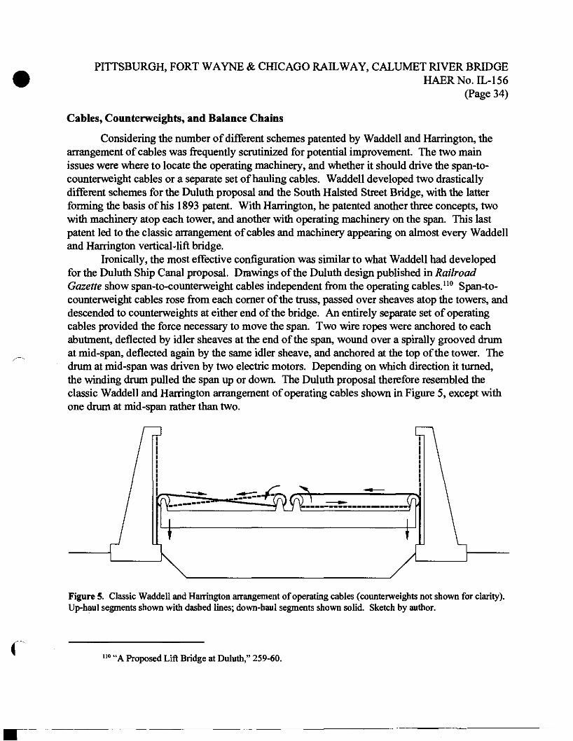
PITTSBURGH, FORT WAYNE & CHICAGO RAILWAY, CALUMET RIVER BRIDGE HAERNo.IL-156
(Page 34)
Cables, Counterweights, and Balance Chains
Considering the number of different schemes patented by Waddell and Harrington, the arrangement of cables was frequently scrutinized for potential improvement. The two main issues were where to locate the operating machinery, and whether it should drive the span-to- counterweight cables or a separate set of hauling cables. Waddell developed two drastically different schemes for the Duluth proposal and the South Halsted Street Bridge, with the latter forming the basis of his 1893 patent. With Harrington, he patented another three concepts, two with machinery atop each tower, and another with operating machinery on the span. This last patent led to the classic arrangement of cables and machinery appearing on almost every Waddell and Harrington vertical-lift bridge.
Ironically, the most effective configuration was similar to what Waddell had developed for the Duluth Ship Canal proposal. Drawings of the Duluth design published in Railroad Gazette show span-to-counterweight cables independent from the operating cables.110 Span-to- counterweight cables rose from each corner of the truss, passed over sheaves atop the towers, and descended to counterweights at either end of the bridge. An entirely separate set of operating cables provided the force necessary to move the span. Two wire ropes were anchored to each abutment, deflected by idler sheaves at the end of the span, wound over a spirally grooved drum at mid-span, deflected again by the same idler sheave, and anchored at the top of the tower. The drum at mid-span was driven by two electric motors. Depending on which direction it turned, the winding drum pulled the span up or down. The Duluth proposal therefore resembled the classic Waddell and Harrington arrangement of operating cables shown in Figure 5, except with one drum at mid-span rather than two.
Figure 5. Classic Waddell and Harrington arrangement of operating cables (counterweights not shown for clarity). Up-haul segments shown with dashed lines; down-haul segments shown solid. Sketch by author.
uo« A Proposed Lift Bridge at Duluth," 259-60.
PITTSBURGH, FORT WAYNE & CHICAGO RAILWAY, CALUMET RIVER BRIDGE HAERNo.IL-156
(Page 35)
When finally implemented at South Halsted Street, some features of Waddell's vertical- lift design were changed from the Duluth proposal. Many of the alterations were for the worse, a fact which Waddell attributed to others. He had wanted electric motors on the span, and complained that his mechanical consultant insisted on steam power, which then had to be located inside one abutment.111 This propagated changes throughout the bridge, most notably an asymmetric arrangement of operating cables. The span-to-counterweight cables were distributed symmetrically, with four l-l/2"-diameter ropes at each corner of the span. As a result of placing the machinery at one end, however, the 7/8"-diameter up-haul ropes going to the far end of the span were significantly longer those at the near end. This became a source of trouble because the longer ropes stretched proportionately more over time, and caused the span to lift unevenly.112
There were no down-haul ropes; the span was lowered by a similar set of up-haul ropes pulling on the counterweights. Furthermore, the operating cables passed over the same sheaves as the counterweight cables, and were anchored at the same points. It would have been difficult to properly tension so many ropes of different diameters and lengths so that each performed its intended function. Nonetheless, this deficient arrangement — not the simpler Duluth proposal — forms the basis of a patent issued to Waddell in October 1893.n3 As the only working prototype of Waddell's vertical-lift design, the unnecessarily complicated South Halsted Street Bridge did not make a good advertisement.
Once Harrington joined the firm, subsequent designs began to address the problem of cable arrangement. The first three patents issued to Waddell and Harrington jointly document this process. In June 1908, they submitted the application that became U.S. Patent No. 953,307, with operating machinery on both towers. This scheme eliminated operating cables entirely, using the machinery to turn the main sheaves. As noted above, the design was not used until 1924. A second patent applied for on 17 August of that year showed a similar arrangement of machinery, but pertained to a lifting deck rather than a lift span.114 This formed the basis of the ASB Bridge at Kansas City, completed in late 1911. Waddell and Harrington's third joint patent, applied for on 31 August, finally approached the classic arrangement shown in Figure 5. The patent's sole claim was for
paired drums revolubly mounted at either end of [the] span, independent pairs of ropes positively fixed to each of said drums, one of the ropes of each pair being attached to the upper portion of one of the towers, and the other rope to a lower
C
111 Waddell, "The Halsted Street Lift-Bridge," 12.
112 van Cleve, "Mechanical Features," 1022.
113 Waddell, "Lift-Bridge," U.S. Patent No. 506,571.
114 Waddell and Harrington, "Lift Bridge," U.S. Patent No. 952,486.
PITTSBURGH, FORT WAYNE & CHICAGO RAILWAY, CALUMET RIVER BRIDGE HAERNo.IL-156
(Page 36)
portion of the same tower, and means carried by the span for actuating said drum.115
The next step was to bring the winding drums closer together, eliminating the longitudinal shaft shown in the patent. This was done on Waddell and Harrington's first jointly designed vertical- lift bridge, for the Iowa Central Railway at Keithsburg, Illinois, in 1909. The machinery was located on the span, with operating cables much smaller than, and clearly separated from, the span-to-counterweight cables. Unlike the arrangement shown in Figure 5, the machinery was located at one end of the span. The unfortunate result, as explained by Howard afterward, was "that the up-haul and down-haul ropes to the far end are 230 ft. longer than to the near end. The extra flexibility of this 230 ft. of rope permitted the far end to oscillate up and down slightly during operation."116 Waddell and Harrington applied this lesson to Portland's Hawthorne Bridge (1910) by placing the operating machinery at mid-span. This constituted a final step in bringing the cables and machinery into the symmetrical arrangement of the mature vertical-lift design.
The Calumet River bridges presented an interesting challenge to the mature vertical-lift design because their movable truss spans are not symmetrical. The skew truss configuration was achieved by offsetting two eight-panel trusses by one panel, making a slight asymmetry in operating cables unavoidable. Even though the machinery house is located at mid-span, it is one panel closer to the west end of the south truss, and one panel closer to the east end of the north truss. The difference of about 26'-3" is relatively small when compared to the operating cables' overall length, however. Otherwise, Waddell and Harrington's vertical-lift design adapted well to the skew alignment. As noted by Howard, the position of the main sheaves is somewhat irrelevant: they can be offset longitudinally, laterally, or even skewed relative to each other.117
Even with movable spans as long as 210'-0" and of heavy railroad construction, the Calumet River bridges retain the vertical-lift bridge's most impressive feature: because the span's weight is more or less balanced by the counterweights, relatively little power is needed to move it. Two 100-horsepower motors wind four 1 "-diameter operating ropes, which seem minuscule in comparison to the forty-eight 2-l/4"-diameter span-to-counterweight ropes on each bridge.
Waddell went to great pains to ensure that the counterweights exactly balanced the span on his early bridges, but experience proved that this was neither possible nor necessary. The appeal of a perfectly balanced span, in his words, was that "all the work which the operating machinery has to do is to overcome the friction, bend the wire ropes, and raise or lower any small
r 115 J. A. L. Waddell and John L. Harrington, "Lift-Bridge," U.S. Patent No. 932,359, 24 Aug. 1909.
116 Ernest E. Howard, discussion following Howard, "Vertical Lift Bridges," 687.
117 Howard, "Vertical Lift Bridges," 583.
PITTSBURGH, FORT WAYNE & CHICAGO RAILWAY, CALUMET RIVER BRIDGE HAERNo.IL-156
(Page 37)
unbalanced load that there may be."118 So that the operator could compensate for debris or precipitation accumulating on the roadway, Waddell provided adjustable water ballast tanks on the South Halsted Street Bridge.119 These awkward devices added unnecessary weight, were probably never used, and were thankfully omitted from subsequent designs. Waddell recognized another source of unbalanced loads in the span-to-counterweight cables, which have considerable weight of their own. If this is not taken into account, the machinery must work against the extra weight of cable as the movable span begins ascending from its closed position. Once the span reaches the halfway mark, the cables make the counterweight side heavier, and the span begins to accelerate upward. WaddelFs solution in the Dumth proposal and on the South Halsted Street Bridge was to drape cast-iron chains from the counterweights to the bottom corners of the truss. As the cables descended on the counterweight side of the sheave, an equivalent weight of chain ascended on the span side, and vice versa. Critics dismissed the balancing chains as superfluous, and they were omitted from several early Waddell and Harrington spans, including the Hawthorne Bridge in Portland. McGaw attributes the decision to Harrington's "concern for mechanical simplicity."120
In the dispute over balancing chains, the Calumet River bridges were the major turning point after which Waddell had the final word. Waddell wrote in 1917 that he
was persuaded, rather against his will, to omit the hydraulic buffers and the balancing chains on the plea that with electric power these are not necessary; but ... he has decided to adopt them again in some of his future vertical lift bridges. In large and heavy lift spans the unbalanced load of the cables augments materially the starting torque and adds to the amount of power used per annum.121
Opinion had already begun turning to favor Waddell, however. The PFW&C's bridge over the Chicago River set a record for lift span length in 1914, and therefore had a relatively large unbalanced cable load. W. L. Smith, a bridge engineer for PRR Lines West, identified its lack of balancing chains as one of three serious deficiencies.122 This lesson was applied to the LS&MS's Calumet River bridges, which were equipped with balancing chains when completed the following year. As further vindication of Waddell's viewpoint, the PFW&C added balancing
118 Statements that the counterweights will "just balance the [dead] weight of the span" in both "A Proposed Lift Bridge at Duluth," 259, and Waddell, "The Halsted Street Lift-Bridge," 4, make it seem that Waddell is the anonymous author of the former.
119 Waddell, "The Halsted Street Lift-Bridge," 6.
120 McGaw, "Hawthorne Bridge," HAER No. OR-20,18.
121 Waddell, "Vertical Lift Bridges," 6:173.
122 W. L. Smith and W. W. Priest, "The Design and Erection of the Pennsylvania Lift Bridge No. 458 over the South Branch of the Chicago River," Journal of the Western Society of Engineers 20, No. 5 (May 1915): 481.
PITTSBURGH, FORT WAYNE & CHICAGO RAILWAY, CALUMET RIVER BRIDGE HAERNo.IL-156
(Page 38)
chains to all of its Chicago vertical-lift bridges afterward.123 All of these railroad bridges now have four balancing chains hanging between each counterweight and the rear tower legs. This arrangement is also an improvement over the South Halsted Street Bridge's chains, which looped beneath the span. Whereas the looped chains had to pass beneath the tower to balance the cables' weight, the new arrangement accomplishes the same purpose while remaining on the counterweight side. This is made possible by calibrating the counterweights JFand the chains H to balance the span S and cables C in the closed position, i.e.,
1V + H = S + C
When the bridge is fully open, the cables are on the counterweight side of the sheaves, but the chains' entire weight hangs from the towers and they drop out of the equation:
w+c = s The chains must therefore be twice as heavy as the cables, as can be determined by solving the above system of equations for H.UA
In reality, a vertical-lift bridge's counterweights and chains are usually designed to make the bridge "span-heavy." This is done intentionally so that the movable span stays put in the closed position. Span-heaviness is critical on the PFW&C bridges, which were not equipped with locks to hold the spans down. This can be attributed to their initial lack of balancing chains, without which the movable spans were significantly heavier when closed.125 When the balancing chains were added, they were designed so that the bridges remained span-heavy. Although the LS&MS bridges had balancing chains from the outset and were span-heavy as well, Waddell and Harrington nonetheless equipped them with locking mechanisms. These consist of 4" x 5" steel bars driven transversely into hangers beneath each corner of the span. A small electric motor on either abutment rotates a cam to actuate the arms to which the bars are attached.126 The span locks were a precautionary measure that may have been dictated by the LS&MS's individual preference. On a later vertical-lift bridge for PRR Lines West at Louisville with otherwise similar mechanical features, Waddell and Son omitted the span locks.127
On all four of the Calumet River bridges, each counterweight consists of three concrete slabs cast over a steel frame. The PFW&C's counterweights have a 1:3:6 mix of cement to sand to furnace slag weighing about 175 pounds per cubic foot. Each set of three slabs originally
r
123 Waddell, discussion following Howard, "Vertical Lift Bridges," 680.
124 These equations were developed by the author.
125 Shortridge Hardesty, discussion following Howard, "Vertical Lift Bridges," 632.
126 Waddell and Harrington, Consulting Engineers, "Bridge No. 6 ... General Arrangement of Bridge Locks " Sheet No. M16A (1 May 1914), in H&C Plan Files.
127 Waddell, discussion following van Cleve, "Mechanical Features," 1039.
PITTSBURGH, FORT WAYNE & CHICAGO RAILWAY, CALUMET RIVER BRIDGE HAERNo.IL-156
(Page 39)
weighed 468.5 tons, including the steel frames.128 (Corresponding data for the LS&MS bridges could not be found.) The slabs on the remaining PFW&C bridge are currently held together by an external steel frame, a feature which is neither original nor found on the LS&MS bridges. These frames hold a small concrete slab on top of each counterweight, which was installed to balance the weight of materials added to the span during the 1990s renovations. On both railroads' bridges, the counterweights have jaws that loosely grip a vertical guide flange on the outside of each tower leg, similar to the movable spans. Maintenance records include an oblique statement that this feature was improved on the LS&MS bridges.129 Because the remaining PFW&C bridge rarely opens far enough to make its counterweights visible from ground level, it was impossible to compare them with the LS&MS bridges'.
Sheaves and Equalizers
The main sheaves over which the cables passed were another point of contention in vertical-lift bridge design. Critics questioned the safety and reliability of wire rope, the repeated bending of which around sheaves and idlers made it susceptible to fatigue and breakage. In Bridge Engineering, Waddell suggested determining the number of ropes by comparing the axial strength of a single rope against a multiple of the hanging loads.130 Critics protested that bending stress might be more critical than axial or "direct" stress, but it did not help that available formulas for bending stresses in wire ropes gave a wide range of results. One discussion in 1921 cited formulas varying by as much as 250 percent.'31 Despite their inconsistency, all of the formulas depended on the ratio of rope diameter to sheave diameter. Waddell's formula was therefore correct for a certain diameter ratio, and the correct ratio was the real point of dispute. Victor H. Cochrane, a competitor in vertical-lift bridge design, suggested a ratio of 80 as a minimum.132 Although some Waddell and Harrington designs went as low as 60, the Calumet River bridges have the recommended 80. Two competing factors made this ratio hard to achieve. The space available on the movable truss's top chord limited the number of ropes that could be attached to it. With larger-diameter ropes, fewer would be required to carry a given load. For a given sheave diameter, however, larger ropes were subjected to greater bending stresses. To keep the bending stresses below the safe limit, the choice became whether to provide smaller ropes or larger sheaves.
r
128 Waddell and Harrington, "Bridge No. 443 ... General Data." The concrete mix is heavier than ordinary structural concrete, which is about 150 pounds per cubic foot.
129 Inspection report, 14 Sep. 1966, in NS Correspondence.
130 Waddell, Bridge Engineering, 2:1712.
131 Victor H. Cochrane, discussion following Howard, "Vertical Lift Bridges," 660.
132 Cochrane, discussion following Howard, "Vertical Lift Bridges," 661, 669.
PITTSBURGH, FORT WAYNE & CHICAGO RAILWAY, CALUMET RIVER BRIDGE HAERNo.IL-156
(Page 40)
As Waddell and Harrington designed longer and longer spans, the sheaves became the limiting factor. They specified cast steel sheaves for their earliest bridges, but the foundry employed to cast the Hawthorne Bridge's 9'-0"-diameter main sheaves had trouble doing so without major flaws. For the Steel Bridge, Waddell and Harrington chose to construct the 14'-0"-diameter main sheaves of sectional rim castings bolted to a built-up steel wheel with a cast steel hub. The bolts failed in service because of an imprecise fit between the rim castings and the disks that formed the side walls of the sheave.133 As mentioned above, this triggered a re-design of similar 15'-0"-diameter sheaves on the PFW&C's Calumet River bridges then under construction. Although the revised design did not depend on an exact fit between rim and disks, it developed a similar flaw elsewhere. The revised sheave design, which had been used on the PFW&C's Chicago River bridge as well, experienced rivet failures around the hub. This time the problem was an imprecise fit between the disks and the hub casting. As explained by van Cleve, "This was corrected by drilling holes into hubs and disks where they come together and driving in slightly tapered tool-steel pins."134 Not surprisingly, the sheave design was revised once again for the LS&MS's Calumet River bridges.
Another, more complex issue was "unequal strain" among the ropes in a cable group, which in early twentieth-century language refers to what today's structural engineers would call unequal stress. Unless every rope in a span-to-counterweight cable group is adjusted to have the same initial length and tension, they will not share the load equally. This is difficult to do on longer bridges, where the heavy movable span and the bending stress limits described above result in a large number of cables (as many as sixty-four on the PFW&C's Chicago River bridge). One problem is the significant initial stretch that occurs when a cable is placed under load, which can be several feet on the typical vertical-lift bridge.135 Each cable can be prestressed before it is attached to the bridge, but might slip slightly in its anchoring socket. Another source of variation is in the lengths of the cables themselves. Although a bridge engineer might specify that a manufacturer supply cables with a certain length under a certain initial load, this measurement is subject to tolerances that accumulate over their great length. In other words, it is entirely possible that no two of the cables in the Calumet River bridges are exactly the same length.
Waddell and Harrington were accused of giving this problem more attention than it deserved. Of the several strain-equalizing devices they developed, separately and as a partnership, none seemed to be completely effective or safe. WaddelTs Duluth and South
133 McGaw, "Steel Bridge," HAERNo. OR-21,26.
134 van Cleve, "Mechanical Features," 1027.
135 Because many steel wire strands are braided together into a rope, the rope behaves differently from a steel rod of equivalent cross-sectional area. When subjected to an axial force, the rod will elongate according to its elastic modulus, a measure of change in length relative to force applied. Individual strands in the rope not only
f~~- lengthen according to their own elastic modulus, but also pull tighter together and straighten out, resulting in " additional elongation. A braided rope can stretch two to four times as much as the equivalent rod.
PITTSBURGH, FORT WAYNE & CHICAGO RAILWAY, CALUMET RIVER BRIDGE HAERNo.IL-156
(Page 41)
Halsted Street designs have complicated devices relying on pulleys to distribute loads evenly among each group of ropes at the counterweights. The Duluth proposal had twelve cast-iron counterweights, arranged in groups of three at each corner of the span. What appeared to be twenty-four span-to-counterweight ropes were actually twelve ropes, anchored to the span, looped around pulleys supporting the counterweights, and doubled back to the span.136 The pulleys ensured that the two halves of each rope were loaded equally by hanging at the lowest point of the loop. On the South Halsted Street Bridge, sixteen loops supported eight cast-iron counterweights. At each counterweight, two ropes looped around separate pulleys, from which a third pulley hung to equalize loads between the first two.137 Although this cumbersome system reduced the number of rope anchorages by half, it also reduced the number of redundant load paths. If a break occurred anywhere in the loop, both halves would fail.
The system developed by Waddell and Harrington for the Keithsburg and Hawthorne bridges was not much safer. It eliminated the loops, but essentially replaced each tier of pulleys with a horizontal rocker bar pierced by three equally spaced pins. Two ropes were anchored to the outermost pins, with the bar pivoting on the middle pin to equalize the load.138 On the Steel Bridge, the equalizers achieved what McGaw calls their "standard" configuration. Instead of horizontal bars, each link is an inverted triangular plate, with the ropes attached to the upper vertices and the pivot point at the lower vertex.139 This made a marginal improvement in safety. "This advantage over the former type is readily seen," stated van Cleve, "when it is realized that to break one rope of a pair in the earlier design would cause the other to receive double its original load."140 As installed on the Calumet River bridges, the triangular equalizer plates were equipped with projecting tabs intended to aid in cable replacement. Despite these refinements, the equalizers did not meet critics' approval. Cochrane called them "completely useless" and submitted a geometric proof that they would not significantly redistribute loads between adjacent ropes of different length. Furthermore, he argued, if an overstressed rope were to break, the resulting sudden redistribution of loads might cause other ropes to break in a chain reaction leading to failure of the bridge.141 Howard conceded that the equalizers could have been omitted, but did not specifically refute Cochrane's point about their safety. A series of equalizer-related
136 "A Proposed Lift Bridge at Duluth," 259-60.
137 This description is based on Waddell, "Lift-Bridge," U.S. Patent No. 506,571.
138 This scheme appears in figs. 11 and 12 of Waddell and Harrington, "Lift-Bridge," U.S. Patent No. 953,307, but as McGaw noted in "Hawthorne Bridge," HAER No. OR-20, 18, it is not included among the claims.
139 McGaw, "Steel Bridge," HAER No. OR-21,27. This does not appear in a patent until John L. Harrington, Ernest E. Howard, and Louis R. Ash, "Retaining-Guide for Counterweight-Ropes," U.S. Patent No. 1,261,124,2 Apr. 1918, but is again not included among the claims.
140 van Cleve, "Mechanical Features," 1022.
141 Cochrane, discussion following Howard, "Vertical Lift Bridges," 663-68.
PITTSBURGH, FORT WAYNE & CHICAGO RAILWAY, CALUMET RIVER BRIDGE HAERNo.IL-156
(Page 42)
mishaps during cable replacements on the Hawthorne Bridge indicate that this system leaves room for improvement.142
Operator's Houses and Appurtenant Structures
One unexpected difference between the pairs of Calumet River bridges is the location of their controls. Like the Hawthorne and Steel bridges before them, the PFW&C's bridges were originally controlled from operator's houses located at mid-span on the movable trusses. On the PFW&C bridges, the 60-square-foot operator's house was suspended beneath the 500-square- foot machinery house. Both houses originally had reinforced concrete walls and timber floors; the machinery was protected by a tin roof on steel framing.143 The remaining PFW&C bridge's machinery house was rebuilt during the 1990s renovations, omitting the operator's house. Controls are now housed in a modern, air-conditioned portable office unit located on the east abutment of the span removed in 1965. The LS&MS bridges have machinery houses similar to the original PFW&C scheme, but their operators did not ride with the movable spans. Instead, they occupied cramped quarters in back-to-back tin boxes wedged up above the clearance line in the east towers' portals. As the author discovered during a visit to the site, these did not afford much of a view of either the river or the approaching tracks. The controls have been substantially gutted since the LS&MS bridges' abandonment.
The railroads also had different philosophies about back-up power for their bridges. Adjacent to the LS&MS spans on the east side of the river is a two-story brick structure known to the NYC as tower "CR" (for Calumet River). According to railroad historian David McLellan, who worked odd jobs on this section of the NYC from 1959 to 1961, the second story served as the tower for the interlocking signal operator. The lower stories, however, were occupied by equipment for the LS&MS bridges.144 Their first source of electrical power was a 4,400-volt line that ran beneath the river to transformers on the east bank. Once stepped down to 440 volts, the current ran motor-generator sets producing 220 volts direct current (DC). A gasoline-powered generator provided an emergency back-up. In case both of these failed, current was drawn from batteries in the basement, which could be charged by either source. Photographs of tower "CR" and its equipment appear in the 31 March 1917 issue of Electrical Review and Western Electrician.145 The gasoline-powered generator can still be found in the building, which has been relegated to storage and is in deteriorating condition for lack of maintenance. The PFW&C had only one emergency power source for its bridges, perhaps for lack of space. There
142 McGaw, "Hawthorne Bridge," HAER No. OR-20,25.
143 Waddell and Harrington, "Bridge No. 443 ... General Data."
144 David McLellan, telephone conversation with author, 26 July 1999.
r"\ l45 "Electric Power for Operating Bridges " Electrical Review and Western Electrician 10, No. 13 (31 Mar. 1917): 528-31.
PITTSBURGH, FORT WAYNE & CHICAGO RAILWAY, CALUMET RIVER BRIDGE HAERNo.IL-156
(Page 43)
was no room in its narrow right-of-way for anything but a small wooden interlocking tower, which has since been demolished. The DC motor-generators and batteries had to be located in a vault beneath the tracks.146 At present, emergency power for the remaining PFW&C bridge is supplied by a gasoline-powered generator located on the east bank behind the modern operator's house.
Conclusion
The most remarkable feature of the Calumet River crossing is the number of movable railroad bridges found there in different stages of preservation. Contrasting the PFW&C bridges with the LS&MS bridges completed two years later, one gets a sense of lessons learned by Waddell and Harrington and applied to improve their design. The remains of a Strauss bascule span on the abandoned B&OCT right-of-way reminds the observer that the vertical-lift design was not the only viable solution to the problem of crossing navigable waterways. After the NYC-PRR merger of 1968, the two LS&MS bridges were mothballed, retaining a number of original features no longer found on vertical-lift spans that have remained in service. Their strange western foundations speak of a mid-course design change. The remaining PFW&C vertical-lift bridge demonstrates its adaptability to changing requirements. It is also resilient: a boat collided with its south truss in November 1920, bending the bottom chord but causing no major damage.147 Even the demolished PFW&C bridge is part of the story, albeit a tragic one proving that vertical-lift bridges are more difficult to dismantle than to erect.
The demolition of a vertical-lift span, already a challenging task, was complicated further because the PFW&C's bridge stood in close proximity to two others. Traffic had declined throughout the twentieth century, to a point where the PFW&C only needed two tracks into Chicago. The railroad took its north span out of service in 1964, and consulted with Boynton Engineering's Chicago office on demolition plans. Boynton recommended a reverse of the erection procedure: bracing the ends of the truss to the towers, removing the middle section of the truss while using the counterweights for balance, removing the counterweights, and taking down the towers. This procedure may have worked if a contractor's hoist had not failed, dropping its load and causing the span to fall into the river. Two employees, standing 300 feet away, were killed by flying shrapnel. The fallen span blocked traffic on the river until it was removed several days later.148
146 McLellan, conversation with author; "Electric Power for Operating Bridges," 531.
147 This may be the damage in a photograph printed in van Cleve, discussion following Howard, "Vertical Lift Bridges," 651; cf. Ferro-Construction Company repair plans in NS aperture cards.
148 "Fallen Bridge Has 11 Ships Trapped Here," Chicago Daily News, 15 Sep. 1965; demolition procedure from D. G. Wheeler of Boynton Engineering, letter to Vincent Figliuczi of the Vindorf Company, n.d., in NS Correspondence.
PITTSBURGH, FORT WAYNE & CHICAGO RAILWAY, CALUMET RIVER BRIDGE HAERNo.IL-156
(Page 44)
The remaining PFW&C bridge, while unquestionably a successful design, has two minor problems that should be mentioned. One persistent source of trouble is the alignment of rails across the skewed ends of the span. Norfolk Southern Railroad, which acquired the bridge from Conrail in 1998, inherited maintenance records showing a history of difficulties with this feature. In January 1969, misaligned rails caused three cars of a freight train to derail on the bridge, fortunately causing only slight damage. Because the rail joints are interlocked with the signal system, misalignments caused numerous delays to traffic from the 1970s onward.149 Norfolk Southern's current plan is to replace the mechanically operated locks with more reliable electrical ones, devices which were not available when Waddell and Harrington designed the bridge. Another problem is deterioration of the counterweights, caused by an alkali-silica reaction between ingredients used in the concrete mix. In 1988, Conrail employees applied an epoxy seal to the counterweights.150 One cannot really blame Waddell and Harrington for this problem either, because its root causes were then unknown to the civil engineering profession.
The remaining PFW&C span, after more than 85 years of continuous and frequent operation, attests to the success of Waddell and Harrington's design. Parts must be replaced on this working machine, but its essential features have not been altered. Components such as motors and controls have been updated with more recent technology. Worn-out cables and sheaves have been replaced, with modern fabrication techniques finally able to accomplish the precise fit demanded by the built-up sheave design.151 The operating machinery, overhauled during the 1990s, nonetheless retains the original configuration of up- and down-haul ropes. Not much has been done to improve the basic framework of Waddell and Harrington's design, the genius of which is its easy accommodation of ever-changing demands.
149 NS Correspondence; cf. "Train Wrecks on Bridge," Chicago American, 29 Jan. 1969.
150 Memorandum, 15 Aug. 1988, in NS Correspondence.
151 On the PFW&C bridges, the first of sixteen original sheaves was replaced with a new sheave in March | 1953. The old sheave was then refurbished and swapped for another old sheave. NS Correspondence contains
specifications for replacing two more sheaves, and refurbishing two more, in July 1953.
PITTSBURGH, FORT WAYNE & CHICAGO RAILWAY, CALUMET RIVER BRIDGE HAERNo.IL-156
(Page 45)
SOURCES CONSULTED
Published
Brown, Kathi A. Diversity by Design: Celebrating 75 Years of Howard Needles Tammen & Bergendoff, 1914-1989. 1st ed. Kansas City, Mo.: Lowell Press, 1989.
Chicago's First Half Century: The City as It Was Fifty Years Ago, and as It Is to-Day. Chicago: Inter Ocean Publishing Co., 1883.
"Comparison of Five Railway Bridge Specifications." Engineering News-Record83, No. 1 (3 July 1919): 33-36.
Congressional Record.
Cortelyou, Frank M., et al. "Memoir of John Lyle Harrington." Transactions of the American Society of Civil Engineers 107(1942): 1768-72.
Cronon, William. Nature's Metropolis: Chicago and the Great West. New York: W. W. Norton & Co., 1991.
"Electric Power for Operating Bridges." Electrical Review and Western Electrician 70, No. 13 (31 Mar. 1917): 528-31.
"Fallen Bridge Has 11 Ships Trapped Here." Chicago Daily News, 15 Sep. 1965.
Frey, Robert L., ed. Encyclopedia of American Business History and Biography: Railroads in the Nineteenth Century. New York: Facts on File, 1988.
"The Halsted St. Lift Bridge over the Chicago River." Engineering News and American Railway Journan\,No. 16 (19 Apr. 1894): 320-21.
Harrington, John L., ed. The Principal Professional Papers of Dr. J. A. L. Waddell, Civil Engineer. 1st ed. New York: Virgil H. Hewes, 1905.
Harrington, John L., Ernest E. Howard, and Louis R. Ash. "Retaining-Guide for Counterweight- Ropes." U.S. Patent No. 1,261,124. 2 Apr. 1918.
Hool, George A., and W. S. Kinne, ed. Movable and Long-Span Steel Bridges. New York: McGraw-Hill, 1923.
Hovey, Otis E. Movable Bridges. 2 vols. New York: John Wiley & Sons, 1927.
Howard, Ernest E., et al. "Vertical Lift Bridges." Transactions of the American Society of Civil Engineers 84 (1921): 580-695.
Howard, W. J. "Erection of a Cable Lift Bridge." Engineering News 70, No. 11 (11 Sep. 1913): 500-01.
C
PITTSBURGH, FORT WAYNE & CHICAGO RAILWAY, CALUMET RIVER BRIDGE HAERNo.IL-156
(Page 46)
Industrial Chicago, vol. 4, The Commercial Interests. Chicago: Goodspeed Publishing Co., 1894.
Jackson, David. "Pennsylvania Steel, 1867-1916." Keystone 31, No. 4 (Winter 1998): 41-50.
"Largest Bascule Bridge." Engineering Record 68, No. 25 (20 Dec. 1913): 697.
Liljencrantz, G. A. M. "Obstructive Bridges and Docks in the Chicago River." Journal of the Western Society of Engineers 3, No. 3 (June 1898): 1056-97.
Mayer, Harold M., and Richard C. Wade. Chicago: Growth of a Metropolis. Chicago: Univ. of Chicago Press, 1969.
McLellan, David, and Bill Warrick. The Lake Shore & Michigan Southern Railway. Polo, 111.: Transportation Trails, 1989.
Meinig, Donald W. The Shaping of America: A Geographical Perspective on 500 Years of History. 3 vols. New Haven: Yale Univ. Press, 1986.
Misa, Thomas J. A Nation of Steel: The Making of Modern America, 1865-1925. Baltimore: Johns Hopkins Univ. Press, 1995.
"A Model Bridge and Construction Shop." Iron Age 72 (10 Sep. 1903): 1-7.
Pennsylvania Railroad Co. Annual Report of the Board of Directors to the Stockholders, for the Year.... Philadelphia: Pennsylvania Railroad Co., 1847 et seq.
. Corporate History of the Pittsburgh, Fort Wayne and Chicago Railway Company, Together with the Mortgages, Leases, Deeds and Agreements of that Corporation, Assumed by the Pennsylvania Company, and in Force August 1, 1875. Pittsburgh: Stevenson & Foster, 1875.
"The Pennsylvania Steel Company's Model Bridge Plant." Engineering Record 48, No. 13 (26 Sep. 1903): 360-63, No. 14 (3 Oct. 1903): 395-99, No. 15 (10 Oct. 1903): 423-26, No. 16 (17 Oct. 1903): 455-58, and No. 17 (24 Oct. 1903): 494-96.
Petroski, Henry. Engineers of Dreams: Great Bridge Builders and the Spanning of America. New York: Alfred A. Knopf, 1995.
Pittsburgh, Fort Wayne & Chicago Railroad Co. First Report of the Board of Directors of the Pittsburgh, Ft. Wayne & Chicago Rail Road Company, to the Stockholders, for the Seventeen Months Ending December SI, 1857. Pittsburgh: W. S. Haven, 1858.
. Fourth Annual Report of the Board of Directors of the Pittsburgh, Fort Wayne and Chicago Rail Road Company, to the Stockholders, for the Year ending December 31st, 1860. Pittsburgh: Barr & Myers, 1861.
f
c
PITTSBURGH, FORT WAYNE & CHICAGO RAILWAY, CALUMET RIVER BRIDGE HAERNo.IL-156
(Page 47)
Pittsburgh, Fort Wayne & Chicago Railway Co. Annual Report of the Board of Directors of the Pittsburgh, Fort Wayne and Chicago Railway Company, to the Stock and Bondholders for the Year Ending... Pittsburgh: W. S. Haven, 1863 et seq.
Prichard, H. S., et al. "Lift Bridges — a Discussion." Proceedings of the Engineers' Society of Western Pennsylvania 25, No. 1 (Feb. 1909): 11-75.
"A Proposed Lift Bridge at Duluth, Minn." Railroad Gazette 24, No. 15 (8 Apr. 1892): 259-60.
"Repairing Halsted Street Vertical Lift Bridge." Railway Engineering and Maintenance of Way 27, No. 10 (Oct. 1912): 470-71.
"Report of Chicago Harbor Commission." Railway and Engineering Review 49, No. 12 (20 Mar. 1909): 274-76.
Sikes, George C. "Report to the Chicago Harbor Commission on Obstacles to Chicago's Water Shipping Development." Marine Review 39, No. 4 (28 Jan. 1909): 26-32.
Simons, Richard D., and Francis H. Parker. Railroads of Indiana. Bloomington: Univ. of Indiana Press, 1997.
Smith, W. L., and W. W. Priest. "The Design and Erection of the Pennsylvania Lift Bridge No. 458 over the South Branch of the Chicago River." Journal of the Western Society of Engineers 20, No. 5 (May 1915): 478-500.
Statutes at Large.
"Steel Guyed Derrick for Bridge Erection," Engineering News 71, No. 24(11 June 1914): 1307- 08.
Stover, John F. History of the Baltimore and Ohio Railroad. West Lafayette, Ind.: Purdue Univ. Press, 1987.
Strauss, Joseph B. "The Bascule Bridge in Chicago." In A Half-Century of Chicago Building, edited by John H. Jones and Fred A. Britten. Chicago: 1910.
Sultan, Daniel I., and D. A. D. Ogden. "Chicago Terminus of the Lakes-to-Gulf Waterway." Civil Engineering 3, No. 8 (Aug. 1933): 413-16.
"Train Wrecks on Bridge." Chicago American, 29 Jan. 1969.
Tyrrell, Henry G. History of Bridge Engineering. Chicago: 1911.
U.S. Army. Corps of Engineers. Annual Report of the Chief of Engineers to the Secretary of War for the Year.... Washington, D.C.: U.S. Government Printing Office, 1876-1906.
. Report of the Chief of Engineers, U.S. Army.... Washington, D.C.: U.S. Government Printing Office, 1907 et seq.
PITTSBURGH, FORT WAYNE & CHICAGO RAILWAY, CALUMET RIVER BRIDGE HAERNo.IL-156
(Page 48)
U.S. Congress. House. Committee on Interstate and Foreign Commerce. Bascule Bridge Across Calumet River, Chicago. 62nd Cong., 2nd sess., 1912. H. Rept. 284.
. House. Committee on the Post Office and Post Roads. Letter from the Postmaster General Submitting a Report Giving the Results of the Inquiry as to the Operation, Receipts, and Expenditures of the Railroad Companies Transporting the Mails, and Recommending Legislation on the Subject. 62nd Cong., 1st sess., 1911. H. Doc. 105.
. Senate. Committee on Commerce. Bridge Across the Calumet River, South Chicago, III 62nd Cong., 2nd sess., 1912. S. Rept. 335.
Vance, James E., Jr. The North American Railroad: Its Origin, Evolution, and Geography. Baltimore: Johns Hopkins Univ. Press, 1995.
van Cleve, Horatio P. "The Mechanical Features of the Vertical Lift Bridge." Transactions of the American Society of Mechanical Engineers 40 (1918): 1017-42.
Waddell, J. A. L. Bridge Engineering. 2 vols. New York: John Wiley & Sons, 1916.
. De Pontibus: A Pocket-book for Bridge Engineers. 1st ed. New York: John Wiley & Sons, 1898.
. "The Halsted Street Lift-Bridge." Transactions of the American Society of Civil Engineers 33 (1895): 1-60.
_. "Lift-Bridge." U.S. Patent No. 506,571. 10 Oct. 1893.
. "Vertical Lift Bridges." In Proceedings of the Second Pan American Scientific Congress, edited by Glen L. Swiggett, 6:170-84. Washington, D.C.: U.S. Government Printing Office, 1917.
Waddell, J. A. L., and John L.Harrington. "Lift Bridge." U.S. Patent No. 952,486. 22 Mar. 1910.
. "Lift-Bridge." U.S. Patent No. 932,359. 24 Aug. 1909.
. "Lift-Bridge." U.S. Patent No. 953,307. 29 Mar. 1910.
. "Lift-Bridge." U.S. Patent No. 1,049,422. 7 Jan. 1913.
Whipple, Squire. "Improvement in Lift Draw-Bridges." U.S. Patent No. 134,338. 24 Dec. 1872.
Unpublished
Alexander, Frances, John Nicolay, and Charles Scott. "Pennsylvania Railroad, Eight-Track Bascule Bridge." HAER No. IL-99. Historic American Engineering Record, National Park Service, U.S. Department of the Interior.
PITTSBURGH, FORT WAYNE & CHICAGO RAILWAY, CALUMET RIVER BRIDGE HAERNo. IL-156
(Page 49)
Alexander, Frances, Carolyn Brucken, Gray Fitzsimons, and John Nicolay. "Pennsylvania Railroad, South Branch Chicago River Bridge." HAERNo. IL-112. Historic American Engineering Record, National Park Service, U.S. Department of the Interior.
Clarke, Jonathan. "City Waterway Bridge." HAERNo. WA-100. Historic American Engineering Record, National Park Service, U.S. Department of the Interior.
Harrington and Cortelyou, Consulting Engineers. Plan files, Kansas City, Mo.
Harrington, John Lyle. Material. MG 2731, Western Historical Manuscript Collection, Ellis Library, University of Missouri, Columbia, Mo.
Heimer, Crew. Telephone conversation with author. 16 June 1999.
John, Richard R. E-mail to author. 11 Dec. 2000.
Mayer, Harold M. "The Railway Pattern of Metropolitan Chicago." Ph.D. diss., Univ. of Chicago, 1943.
McGaw, Judith A. "Hawthorne Bridge." HAER No. OR-20. Historic American Engineering Record, National Park Service, U.S. Department of the Interior.
. "Steel Bridge." HAERNo. OR-21. Historic American Engineering Record, National Park Service, U.S. Department of the Interior.
McLellan, David. Telephone conversation with author. 26 July 1999.
Norfolk Southern Railroad. Aperture cards and correspondence files, Atlanta, Ga.
Waddell and Harrington, Consulting Engineers. "Bridge No. 443 over the Calumet River, Chicago, 111., Pennsylvania Lines West of Pittsburgh, Chicago Terminal Division, N. W. System." Set of drawings. Chicago Line milepost 509.60, aperture card files, Norfolk Southern Railroad, Atlanta, Ga.
. "Bridge No. 6 over the Calumet River, Chicago, 111., Lake Shore & Michigan Southern R. R., Western Division, Two Track Design." Set of drawings. Plan files, Harrington and Cortelyou Consulting Engineers, Kansas City, Mo.
Located in Project Files, Chicago District, U.S. Army Corps of Engineers, Chicago, 111.
Bixby, W. H. "Suggestions (1908) for New Draw Spans of 120 Feet Clear Width, and Bascule Bridges of About 225 Feet Length Between Bearings, for R.R. Crossings over Calumet River near 97th Street, Chicago, 111." Calumet River Sheet No. 235.
Heinze, Paul. "B. and O. R. R. Location of Bridges Calumet River, South Chicago, 111.," 23 Sep. 1899. Calumet River Sheet No. 137.
P
PITTSBURGH, FORT WAYNE & CHICAGO RAILWAY, CALUMET RIVER BRIDGE HAERNo.IL-156
(Page 50)
_. "Map Showing U.S. Dock Lines of Calumet River, 111.," 1896. Calumet River Sheet No. 118.
Kelly-Atkinson Construction Co. "Location Diagram: Pile Plan for False Work, Bridge #443, Penn. Ry. Co., So. Chicago, 111.," July 1912. Calumet River Sheet No. 273.
Lake Shore & Michigan Southern Railway. Bridge Department. "Proposed Bridge No. 6, Western Div., over Calumet River, South Chicago, 111.: Location Plan," 16 Jan. 1911. Calumet River Sheet No. 273.
. "Proposed Four Track Lift Bridge across Calumet River, South Chicago, 111.," 7 Apr. 1911. Calumet River Sheet No. 271.
. "Bridge No. 6, Western Division, over Calumet River, Chicago, Illinois: Foundation Plan, Piers and Bracing," 27 Aug. 1912. Calumet River Sheet No. 273.
. "Bridge No. 6, Western Division, over Calumet River, Chicago, 111.: Location Plan for Foundation Bolts," 29 Aug. 1912. Calumet River Sheet No. 273.
. "Bridge No. 6, Western Division, over Calumet River, Chicago, 111.: Plan of Concrete Abutments," 4 Dec. 1912. Calumet River Sheet No. 273.
"L. S. & M. S. Ry. Co.'s Draw Bridge over Calumet River at South Chicago," n.d. Calumet River Sheet No. illegible.
Liljencrantz, G. A. M. "Map of Calumet Harbor, Illinois, Surveyed and Drawn under the Direction of Major G. L. Gillespie, Corps of Engineers U. S. Army," 24 July 1875. Calumet Harbor Sheet No. 11.
"The Location of the Drawbridge on the Pittsburgh Fort Wayne and Chicago Railway over the Calumet River...," 1874. Calumet River Sheet No. 7.
Pittsburgh, Fort Wayne & Chicago Railway. "Calumet River Bridge, Chicago, 111.: Cable Tunnel Under Calumet River (High & Low Tension)," 24 Aug. 1911. Calumet River Sheet No. 269.
"Sketch Plan Showing Proposed Location of Two Channels — 90 Ft. Clear Width with Center Rest Pier," 5 Dec. 1909. Calumet River Sheet No. 244.
U.S. Army. Corps of Engineers. "Map Showing U.S. Dock Lines of Calumet River, III.," 1904. Calumet River Sheet No. 181.
. "Calumet River Alignment of Pier Protections at the P. F. W. & C. Ry., L. S. & M. S. Ry., and B. & O. R. R. Bridges," 8 May 1916. Calumet River Sheet No. 337.
r
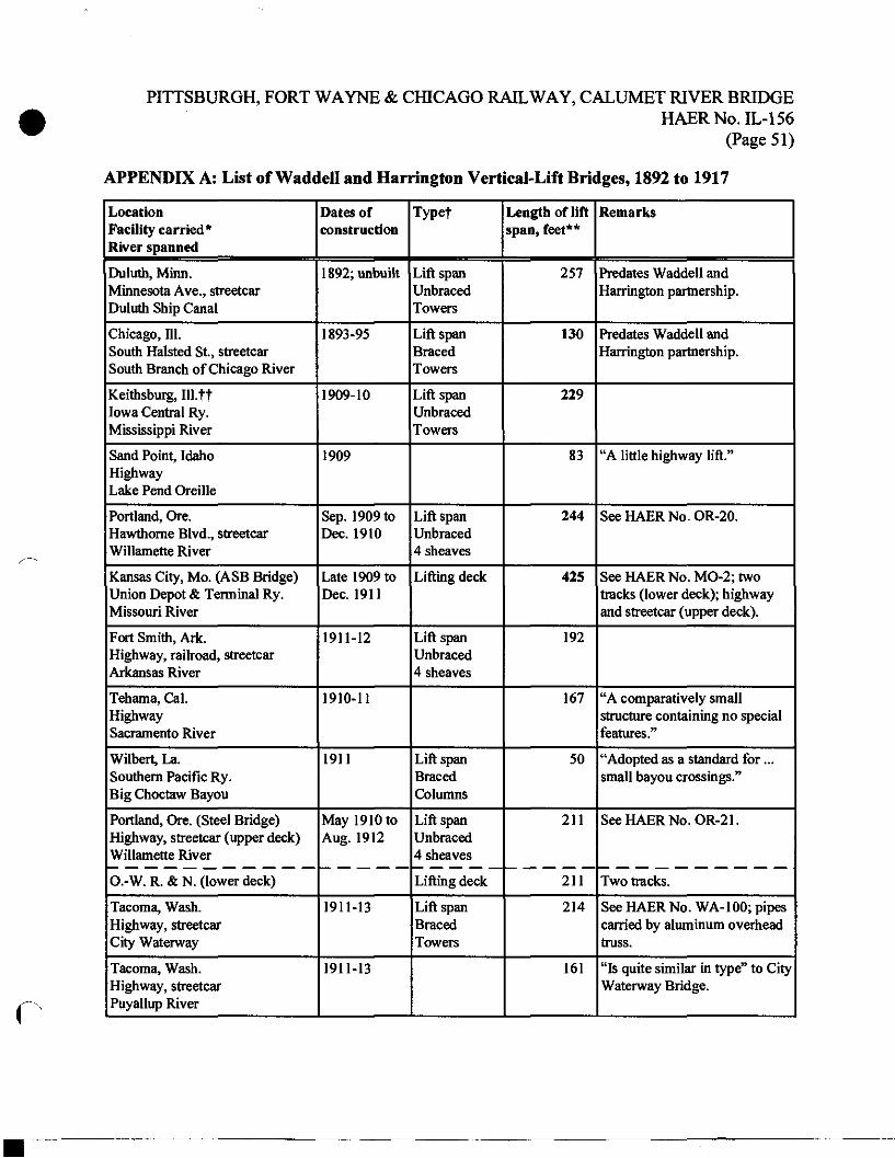
PITTSBURGH, FORT WAYNE & CHICAGO RAILWAY, CALUMET RIVER BRIDGE HAERNo.IL-156
(Page 51)
APPENDIX A: List of Waddell and Harrington Vertical-Lift Bridges, 1892 to 1917
Location Facility carried* River spanned
Dates of construction
Typef Length of lift span, feet**
Remarks
Duluth, Minn. Minnesota Ave., streetcar Duluth Ship Canal
1892; unbuilt Lift span Unbraced Towers
257 Predates Waddell and Harrington partnership.
Chicago, 111. South Halsted St., streetcar South Branch of Chicago River
1893-95 Lift span Braced Towers
130 Predates Waddell and Harrington partnership.
Keithsburg, Ill.tt Iowa Central Ry. Mississippi River
1909-10 Lift span Unbraced Towers
229
Sand Point, Idaho Highway Lake Pend Oreille
1909 83 "A little highway lift."
Portland, Ore. Hawthorne Blvd., streetcar Willamette River
Sep. 1909 to Dec. 1910
Lift span Unbraced 4 sheaves
244 SeeHAERNo.OR-20.
Kansas City, Mo. (ASB Bridge) Union Depot & Terminal Ry. Missouri River
Late 1909 to Dec. 1911
Lifting deck 425 See HAER No. MO-2; two tracks (lower deck); highway and streetcar (upper deck).
Fort Smith, Ark. Highway, railroad, streetcar Arkansas River
1911-12 Lift span Unbraced 4 sheaves
192
Tehama, Cal. Highway Sacramento River
1910-11 167 "A comparatively small structure containing no special features."
Wilbert, La. Southern Pacific Ry. Big Choctaw Bayou
1911 Lift span Braced Columns
50 "Adopted as a standard for... small bayou crossings."
Portland, Ore. (Steel Bridge) Highway, streetcar (upper deck) Willamette River
May 1910 to Aug. 1912
Lift span Unbraced 4 sheaves
211 SeeHAERNo.OR-21.
O.-W. R. & N. (lower deck) Lifting deck 211 Two tracks.
Tacoma, Wash. Highway, streetcar City Waterway
1911-13 Lift span Braced Towers
214 See HAER No. WA-100; pipes carried by aluminum overhead truss.
Tacoma, Wash. Highway, streetcar Puyallup River
1911-13 161 "Is quite similar in type" to City Waterway Bridge.
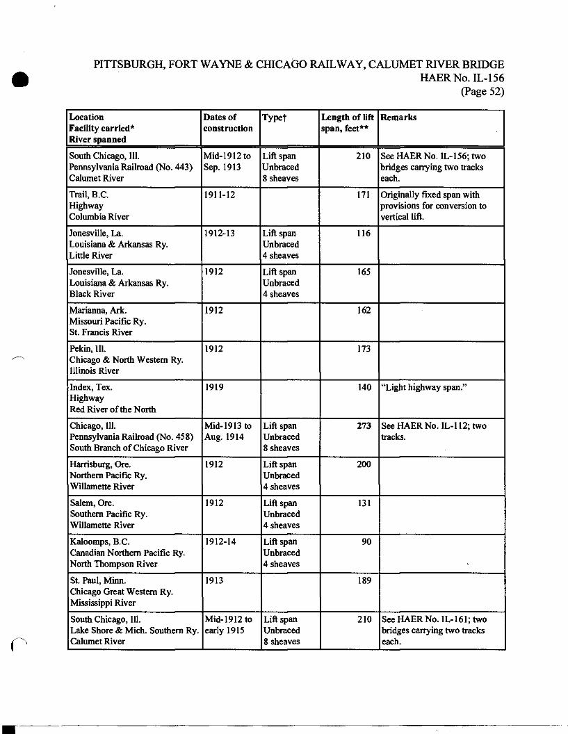
PITTSBURGH, FORT WAYNE & CHICAGO RAILWAY, CALUMET RIVER BRIDGE HAERNo.IL-156
(Page 52)
Location Facility carried* River spanned
Dates of construction
Typef Length of lift span, feet**
Remarks
South Chicago, 111. Pennsylvania Railroad (No. 443) Calumet River
Mid-1912 to Sep. 1913
Lift span Unbraced 8 sheaves
210 See HAERNo.IL-156; two bridges carrying two tracks each.
Trail, B.C. Highway Columbia River
1911-12 171 Originally fixed span with provisions for conversion to vertical lift.
Jonesville, La. Louisiana & Arkansas Ry. Little River
1912-13 Lift span Unbraced 4 sheaves
116
Jonesville, La. Louisiana & Arkansas Ry. Black River
1912 Lift span Unbraced 4 sheaves
165
Marianna, Ark. Missouri Pacific Ry. St. Francis River
1912 162
Pekin, 111. Chicago & North Western Ry. Illinois River
1912 173
Index, Tex. Highway Red River of the North
1919 140 "Light highway span."
Chicago, 111. Pennsylvania Railroad (No. 4S8) South Branch of Chicago River
Mid-1913 to Aug. 1914
Lift span Unbraced 8 sheaves
273 SeeHAERNo.IL-112;two tracks.
Harrisburg, Ore. Northern Pacific Ry. Willamette River
1912 Lift span Unbraced 4 sheaves
200
Salem, Ore. Southern Pacific Ry. Willamette River
1912 Lift span Unbraced 4 sheaves
131
Kaloomps, B.C. Canadian Northern Pacific Ry. North Thompson River
1912-14 Lift span Unbraced 4 sheaves
90
St. Paul, Minn. Chicago Great Western Ry. Mississippi River
1913 189
South Chicago, 111. Lake Shore & Mich. Southern Ry. Calumet River
Mid-1912 to early 1915
Lift span Unbraced 8 sheaves
210 See HAERNo. IL-161; two bridges carrying two tracks each.
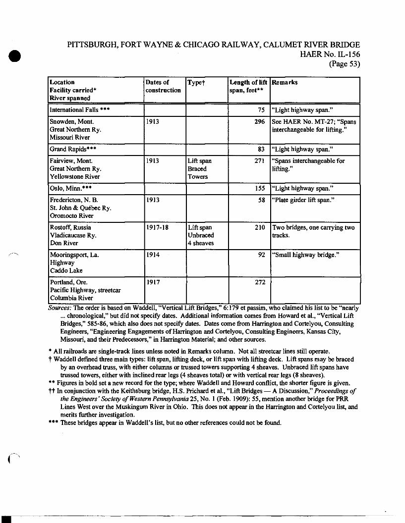
PITTSBURGH, FORT WAYNE & CHICAGO RAILWAY, CALUMET RIVER BRIDGE HAERNo.IL-156
(Page 53)
Location Facility carried* River spanned
Dates of construction
Typet Length of lift span, feet**
Remarks
International Falls *** 75 "Light highway span."
Snowden, Mont. Great Northern Ry. Missouri River
1913 296 See HAER No. MT-27; "Spans interchangeable for lifting."
Grand Rapids*** 83 "Light highway span."
Fairview, Mont. Great Northern Ry. Yellowstone River
1913 Lift span Braced Towers
271 "Spans interchangeable for lifting."
Oslo, Minn.*** 155 "Light highway span."
Fredericton, N. B. St. John & Quebec Ry. Oromocto River
1913 58 "Plate girder lift span."
Rostoff, Russia Vladicaucase Ry. Don River
1917-18 Lift span Unbraced 4 sheaves
210 Two bridges, one carrying two tracks.
Mooringsport, La. Highway Caddo Lake
1914 92 "Small highway bridge."
Portland, Ore. Pacific Highway, streetcar Columbia River
1917 272
Sources: The order is based on Waddell, "Vertical Lift Bridges," 6:179 et passim, who claimed his list to be "nearly ... chronological," but did not specify dates. Additional information comes from Howard et al., "Vertical Lift Bridges," 585-86, which also does not specify dates. Dates come from Harrington and Cortelyou, Consulting Engineers, "Engineering Engagements of Harrington and Cortelyou, Consulting Engineers, Kansas City, Missouri, and their Predecessors," in Harrington Material; and other sources.
* All railroads are single-track lines unless noted in Remarks column. Not all streetcar lines still operate. t Waddell defined three main types: lift span, lifting deck, or lift span with lifting deck. Lift spans may be braced
by an overhead truss, with either columns or trussed towers supporting 4 sheaves. Unbraced lift spans have trussed towers, either with inclined rear legs (4 sheaves total) or with vertical rear legs (8 sheaves).
** Figures in bold set a new record for the type; where Waddell and Howard conflict, the shorter figure is given. tf In conjunction with the Keithsburg bridge, H.S. Prichard et al., "Lift Bridges — A Discussion," Proceedings of
the Engineers' Society of Western Pennsylvania 25, No. 1 (Feb. 1909): 55, mention another bridge for PRR Lines West over the Muskingum River in Ohio. This does not appear in the Harrington and Cortelyou list, and merits further investigation.
*** These bridges appear in Waddell's list, but no other references could not be found.
r
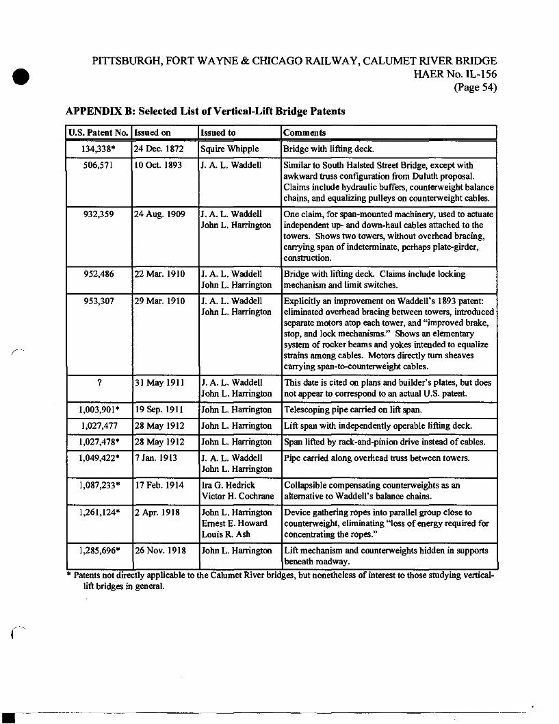
PITTSBURGH, FORT WAYNE & CHICAGO RAILWAY, CALUMET RIVER BRIDGE HAERNo.IL-156
(Page 54)
APPENDIX B : Selected List of Vertical-Lift Bridge Patents
U.S. Patent No. Issued on Issued to Comments
134,338* 24 Dec. 1872 Squire Whtpple Bridge with lifting deck.
506,571 10 Oct. 1893 J. A. L. Waddell Similar to South Halsted Street Bridge, except with awkward truss configuration from Duluth proposal. Claims include hydraulic buffers, counterweight balance chains, and equalizing pulleys on counterweight cables.
932,359 24 Aug. 1909 J. A. L. Waddell John L. Harrington
One claim, for span-mounted machinery, used to actuate independent up- and down-haul cables attached to the towers. Shows two towers, without overhead bracing, carrying span of indeterminate, perhaps plate-girder, construction.
952,486 22 Mar. 1910 J. A. L. Waddell John L. Harrington
Bridge with lifting deck. Claims include locking mechanism and limit switches.
953,307 29 Mar. 1910 J. A. L. Waddell John L. Harrington
Explicitly an improvement on Waddell's 1893 patent: eliminated overhead bracing between towers, introduced separate motors atop each tower, and "improved brake, stop, and lock mechanisms." Shows an elementary system of rocker beams and yokes intended to equalize strains among cables. Motors directly turn sheaves carrying span-to-counterweight cables.
? 31 May 1911 J. A. L. Waddell John L. Harrington
This date is cited on plans and builder's plates, but does not appear to correspond to an actual U.S. patent.
1,003,901* 19 Sep. 1911 John L. Harrington Telescoping pipe carried on lift span.
1,027,477 28 May 1912 John L. Harrington Lift span with independently operable lifting deck.
1,027,478* 28 May 1912 John L. Harrington Span lifted by rack-and-pinion drive instead of cables.
1,049,422* 7 Jan. 1913 J. A. L. Waddell John L. Harrington
Pipe carried along overhead truss between towers.
1,087,233* 17 Feb. 1914 Ira G. Hedrick Victor H. Cochrane
Collapsible compensating counterweights as an alternative to Waddell's balance chains.
1,261,124* 2 Apr. 1918 John L. Harrington Ernest E. Howard Louis R. Ash
Device gathering ropes into parallel group close to counterweight, eliminating "loss of energy required for concentrating the ropes."
1,285,696* 26 Nov. 1918 John L. Harrington Lift mechanism and counterweights hidden in supports beneath roadway.
* Patents not directly applicable to the Calumet River bridges, but nonetheless of interest to those studying vertical- lift bridges in general.
PITTSBURGH, FORT WAYNE & CHICAGO RAILWAY, CALUMET RIVER BRIDGE HAERNo.IL-156
(Page 55)
APPENDIX C: Baltimore & Ohio Chicago Terminal Railroad, Calumet River Bridge
This list of sources will aid the reader interested in studying this structure, which was not documented before its destruction in the 1980s.
"Calumet River Bascule Bridge, B. & O. R.R." Railway Engineering and Maintenance of Way n.s. 9 [o.s. 28], No. 3 (Mar. 1913): 115-17.
"The Calumet River Drawbridge, Baltimore & Ohio R. R." Engineering Record 50, No. 22 (26 Nov. 1904): 636-37.
"Calumet River Drawbridge Substructure." Engineering Record66, No. 4 (27 July 1912): 94- 95.
"Largest Bascule Bridge." Engineering Record 68, No. 25 (20 Dec. 1913): 697.
"Piers for Drawbridge over Calumet River." Engineering Record 67, No. 8 (22 Feb. 1913): 208.
"Strauss Bascule Bridge." Railway Age Gazette 52, No. 11C (21 Mar. 1912): 662-64.
"Strauss Bascule Bridge at South Chicago." Railway Age Gazette 54, No. 12 (19 Mar. 1913): 605-06.
c