pk-1000usermanualstatics3.seeedstudio.com/.../pk-1000_user_manual.pdf ·...
TRANSCRIPT

Pk-1000 User Manual
Version 1.0
13-05-2017

PrefacePk-1000 UWB is a positioning / distance measuring product based on IR UWB.
This specification introduces PK-1000 and the configuration of it.
The following content is included in Preface:
- The Readers
- The Annotation
- Technical Supports
The Readers
This booklet is prepared for the following people:
- Students and teachers
- Amateur developers
- Engineers
The Annotation
Please note that the bold text in this booklet requires extra attention.
Technical Support
If you have any problems about using the products (both software and
hardware), don’t hesitate to contact us. Contact information can be found in
trough [email protected].
Table of content
1. Interfaces defination.........................................................................................................1
1.1 PK-1000 tag WIFI interface......................................................................................1
1.2 PK-1000 tag dataOutputSerial interface..............................................................3
1.3 PK-1000 tag componentsListSerial interface......................................................3
1.4 PK-1000 tag CAN interface......................................................................................4
1.5 PK-1000 tag Power interface..................................................................................5
1.6 PK-1000 anchor Power............................................................................................5
1.7 PK-1000 anchor DIP switch.....................................................................................5
2. Hardware module code upgrade...................................................................................6
2.1 PK-1000 tag code upgrade......................................................................................6
2.1.1 ISP upgrade.......................................................................................................6
2.1.2 SWD upgrade....................................................................................................7
2.2 PK-1000 anchor code upgrade.............................................................................. 7
2.2.1 SWD upgrade....................................................................................................7
3. RLKit manual.......................................................................................................................7
3.1 Connection....................................................................................................................7
3.1.1 Serial ports.............................................................................................................7
3.1.2 TCP........................................................................................................................8
3.2 Set up information...................................................................................................... 9
3.3 Data table and diagram..............................................................................................9
PK-1000 User Manual
- 1 -
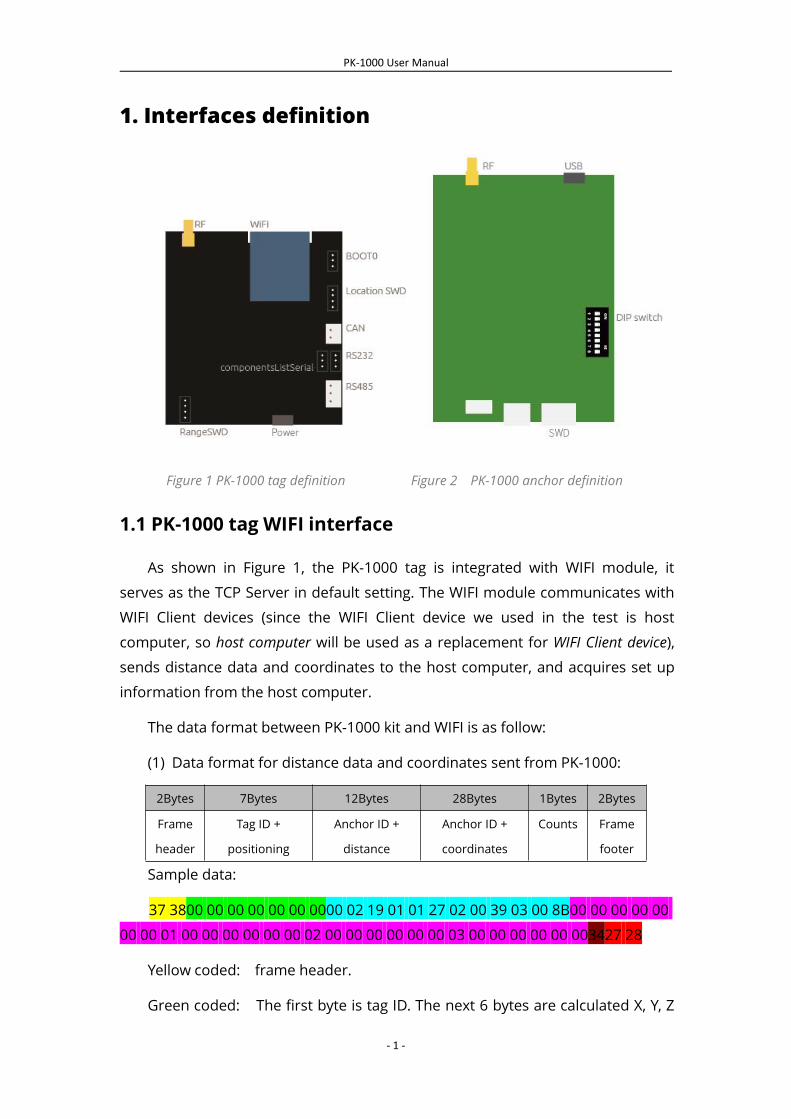
1. Interfaces definition
Figure 1 PK-1000 tag definition Figure 2 PK-1000 anchor definition
1.1 PK-1000 tag WIFI interface
As shown in Figure 1, the PK-1000 tag is integrated with WIFI module, it
serves as the TCP Server in default setting. The WIFI module communicates with
WIFI Client devices (since the WIFI Client device we used in the test is host
computer, so host computer will be used as a replacement for WIFI Client device),
sends distance data and coordinates to the host computer, and acquires set up
information from the host computer.
The data format between PK-1000 kit and WIFI is as follow:
(1) Data format for distance data and coordinates sent from PK-1000:
2Bytes 7Bytes 12Bytes 28Bytes 1Bytes 2Bytes
Frame
header
Tag ID +
positioning
Anchor ID +
distance
Anchor ID +
coordinates
Counts Frame
footer
Sample data:
37 3800 00 00 00 00 00 0000 02 19 01 01 27 02 00 39 03 00 8B00 00 00 00 00
00 00 01 00 00 00 00 00 00 02 00 00 00 00 00 00 03 00 00 00 00 00 003427 28
Yellow coded: frame header.
Green coded: The first byte is tag ID. The next 6 bytes are calculated X, Y, Z
PK-1000 User Manual
- 2 -
coordinates, every two bytes represents one value. The unit of the coordinates is
CM.
Blue coded: every 3 bytes make a section, there are 4 sections in total. The
first byte of each section is anchor ID, the next 2 bytes is the distance between
this anchor and the tag. The unit of the distance is CM.
Purple coded: every 7 bytes make a section, there are 4 sections in total.
The first byte of each section is anchor ID, the next 6 bytes are the X, Y, Z
coordinates of this anchor. The unit of the coordinates is CM.
Brown coded: counts output.
Red coded: frame footer.
(2) Data format of the setup information received by PK-1000 tag from host
computer:
2Bytes 4Bytes 24Bytes 1Bytes 2Bytes
Frame header Anchor ID Anchor coordinates Tag ID Frame footer
Sample data:
93 8301 02 03 0401 00 fe b9 01 53 01 00 fe b9 01 53 01 00 fe b9 01 53 01 00
fe b9 01 530785 95
Yellow coded: frame header.
Green coded: ID of selected anchors, the tag will communicates with these
four anchors to measure distances.
Blue coded: every 6 bytes make a section. There are 4 sections in total. The 6
bytes in every section is the X, Y, Z coordinates of this certain anchor. The unit of
the coordinates is CM.
Purple coded: tag ID.
Red coded: frame footer.
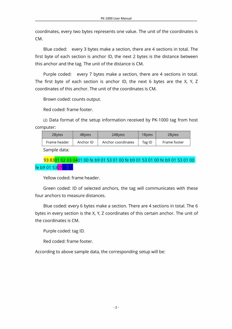
According to above sample data, the corresponding setup will be:
PK-1000 User Manual
- 3 -
Figure 3 Anchors setup
1.2 PK-1000 dataOutputSerial interface
As illustrated in Figure 1, the dataOutputSerial interface on PK-1000 is
designed to send distance & coordinates data, and receive set up information
from host computer. On the other hand, dataOutputSerial receives and sends
TTL level signal through RS232 interface. The level signal can be conversed to
differential signal through RS485 interface, and thus, you can directly integrate
PK-1000 into the RS485 communication bus of any third party products.
The communication format for data through dataOutputSerial interface is as
follow:
(1) Data format for distance data and coordinates sent from PK-1000:
The data format is the same as for WIFI interface.
(2) Data format of the setup information received by PK-1000 tag from host
computer:
The data format is the same as for WIFI interface.
1.3 PK-1000 tag componentsListSerial interface
As illustrated in Figure 1, the componentsListSerial interface on PK-1000
provides the tag ID and default anchors’ ID when PK-1000 is powered on. It can
also be used for code upgrade through ISP protocol. In this situation, please
make sure you’ve shorted BOOT with 3.3V.
Otherwise, please short BOOT with GND before you power up PK-1000, to
guarantee normal function.

PK-1000 User Manual
- 4 -
(1) The data format that componentsListSerial provides when PK-1000 is
powered on:
Please connect componentsListSerial to Serial Debugging Assistant on your
computer before you power the board.
Figure 4 componentsListSerial output
You can find tag ID, default anchors ID, coordinates for default anchors in
Figure 4.
(2) componentsListSerial can also be used as ISP.
1.4 PK-1000 tag CAN interface
As illustrated in Figure 1, the CAN interface on PK-1000 gives you the access
to integrate PK-1000 directly into the CAN net of your products. CAN sends
distance and coordinates to the CAN net. Default ID for CAN device is 0x0002.
(1) The data format for distance sent by CAN is as follow:
1 2 3 4 5 6 7 8
Rn1_H Rn1_L Rn2_H Rn2_L Rn3_H Rn3_L Rn4_H Rn4_L
Rx_H (x=0, 1, 2, 3...) : the highBit of the distance data between tag and each
anchor. The unit of distance is CM.
Rx_L (x=0, 1, 2, 3...) : the lowBit of the distance between tag and each anchor.
The unit of distance is CM.
(2) The data format of coordinates sent by CAN is as follow:
1 2 3 4 5 6 7 8
0x37 TagX_H TagX_H TagY_H TagY_H TagZ_H TagZ_H 0x27
TagX_H: the highBit of x-coordinate in CM.
TagX_L: the lowBit of x-coordinate in CM.
PK-1000 User Manual
- 5 -
TagY_H: the highBit of y-coordinate in CM.
TagY_L: the lowBit of y-coordinate in CM.
TagZ_H: the highBit of z-coordinate in CM.
TagZ_L: the lowBit of z-coordinate in CM.
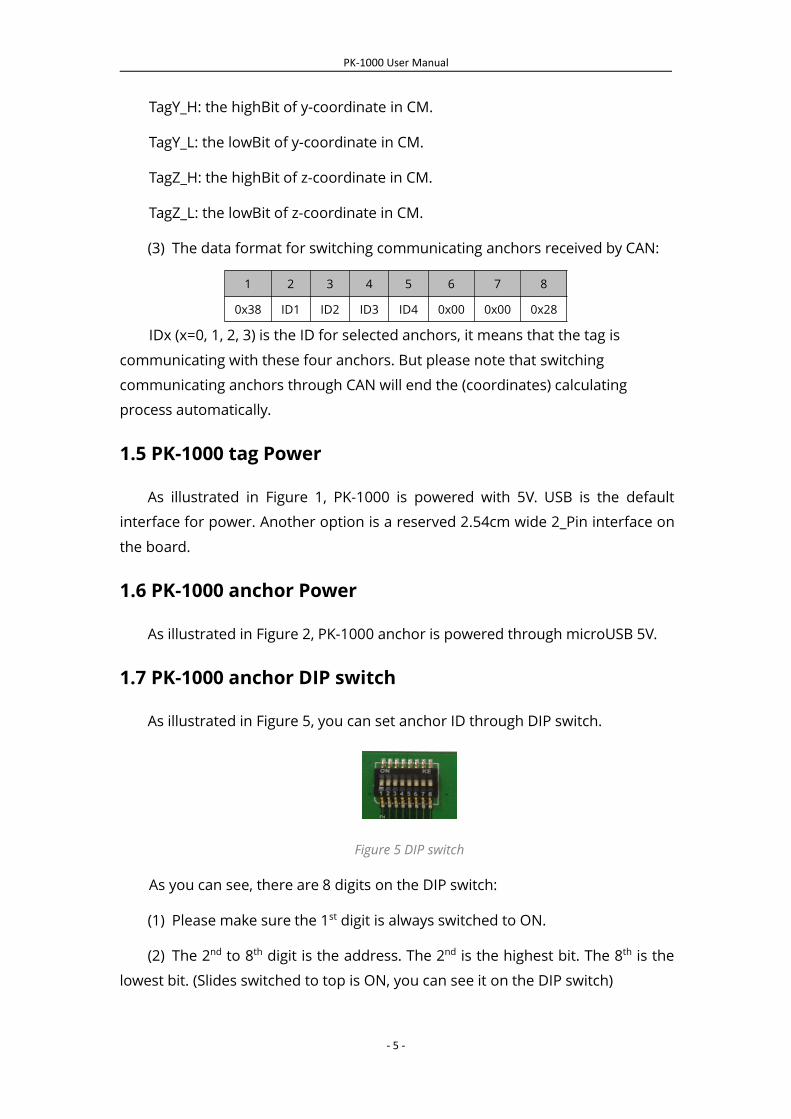
(3) The data format for switching communicating anchors received by CAN:
1 2 3 4 5 6 7 8
0x38 ID1 ID2 ID3 ID4 0x00 0x00 0x28
IDx (x=0, 1, 2, 3) is the ID for selected anchors, it means that the tag is
communicating with these four anchors. But please note that switching
communicating anchors through CAN will end the (coordinates) calculating
process automatically.
1.5 PK-1000 tag Power
As illustrated in Figure 1, PK-1000 is powered with 5V. USB is the default
interface for power. Another option is a reserved 2.54cm wide 2_Pin interface on
the board.
1.6 PK-1000 anchor Power
As illustrated in Figure 2, PK-1000 anchor is powered through microUSB 5V.
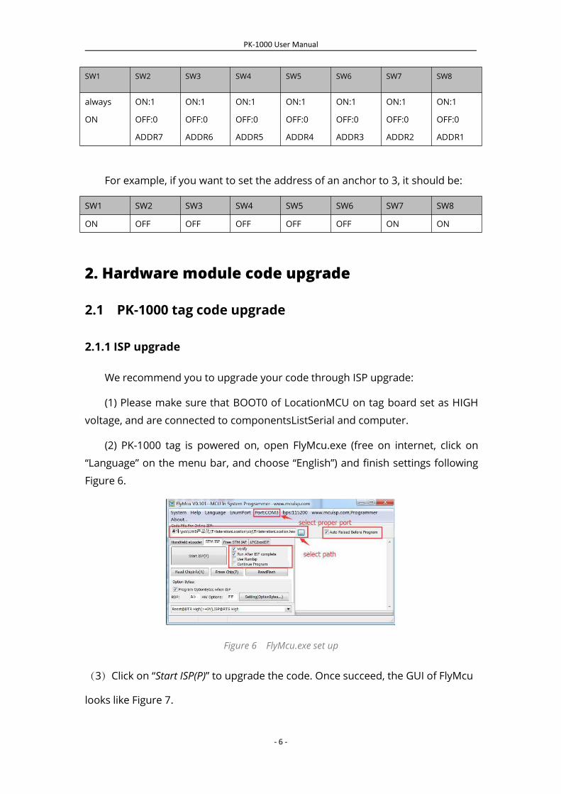
1.7 PK-1000 anchor DIP switch
As illustrated in Figure 5, you can set anchor ID through DIP switch.
Figure 5 DIP switch
As you can see, there are 8 digits on the DIP switch:
(1) Please make sure the 1st digit is always switched to ON.
(2) The 2nd to 8th digit is the address. The 2nd is the highest bit. The 8th is the
lowest bit. (Slides switched to top is ON, you can see it on the DIP switch)
PK-1000 User Manual
- 6 -
SW1 SW2 SW3 SW4 SW5 SW6 SW7 SW8
always
ON
ON:1
OFF:0
ADDR7
ON:1
OFF:0
ADDR6
ON:1
OFF:0
ADDR5
ON:1
OFF:0
ADDR4
ON:1
OFF:0
ADDR3
ON:1
OFF:0
ADDR2
ON:1
OFF:0
ADDR1
For example, if you want to set the address of an anchor to 3, it should be:
SW1 SW2 SW3 SW4 SW5 SW6 SW7 SW8
ON OFF OFF OFF OFF OFF ON ON
2. Hardware module code upgrade
2.1 PK-1000 tag code upgrade
2.1.1 ISP upgrade
We recommend you to upgrade your code through ISP upgrade:
(1) Please make sure that BOOT0 of LocationMCU on tag board set as HIGH
voltage, and are connected to componentsListSerial and computer.
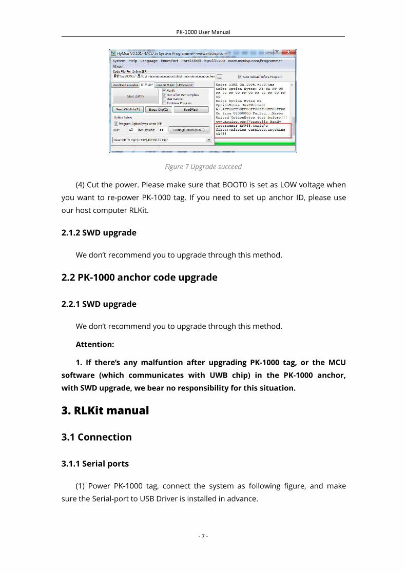
(2) PK-1000 tag is powered on, open FlyMcu.exe (free on internet, click on
“Language” on the menu bar, and choose “English”) and finish settings following
Figure 6.
Figure 6 FlyMcu.exe set up
(3)Click on “Start ISP(P)” to upgrade the code. Once succeed, the GUI of FlyMcu
looks like Figure 7.
PK-1000 User Manual
- 7 -
Figure 7 Upgrade succeed
(4) Cut the power. Please make sure that BOOT0 is set as LOW voltage when
you want to re-power PK-1000 tag. If you need to set up anchor ID, please use
our host computer RLKit.
2.1.2 SWD upgrade
We don’t recommend you to upgrade through this method.
2.2 PK-1000 anchor code upgrade
2.2.1 SWD upgrade
We don’t recommend you to upgrade through this method.
Attention:
1. If there’s any malfuntion after upgrading PK-1000 tag, or the MCUsoftware (which communicates with UWB chip) in the PK-1000 anchor,with SWD upgrade, we bear no responsibility for this situation.
3. RLKit manual
3.1 Connection
3.1.1 Serial ports
(1) Power PK-1000 tag, connect the system as following figure, and make
sure the Serial-port to USB Driver is installed in advance.
PK-1000 User Manual
- 8 -
Figure 8 Serial connection
(2) As illustrated in Figure 9, open RLKit, select correct serial port, and
click ”Open”.
Figure 9 connect host computer through serial port
3.1.2 TCP
(1) Powered up PK-1000. Select the correct WIFI ”BeiLa”. The password is
12345678.
Figure 10 Connect to BeiLa WIFI
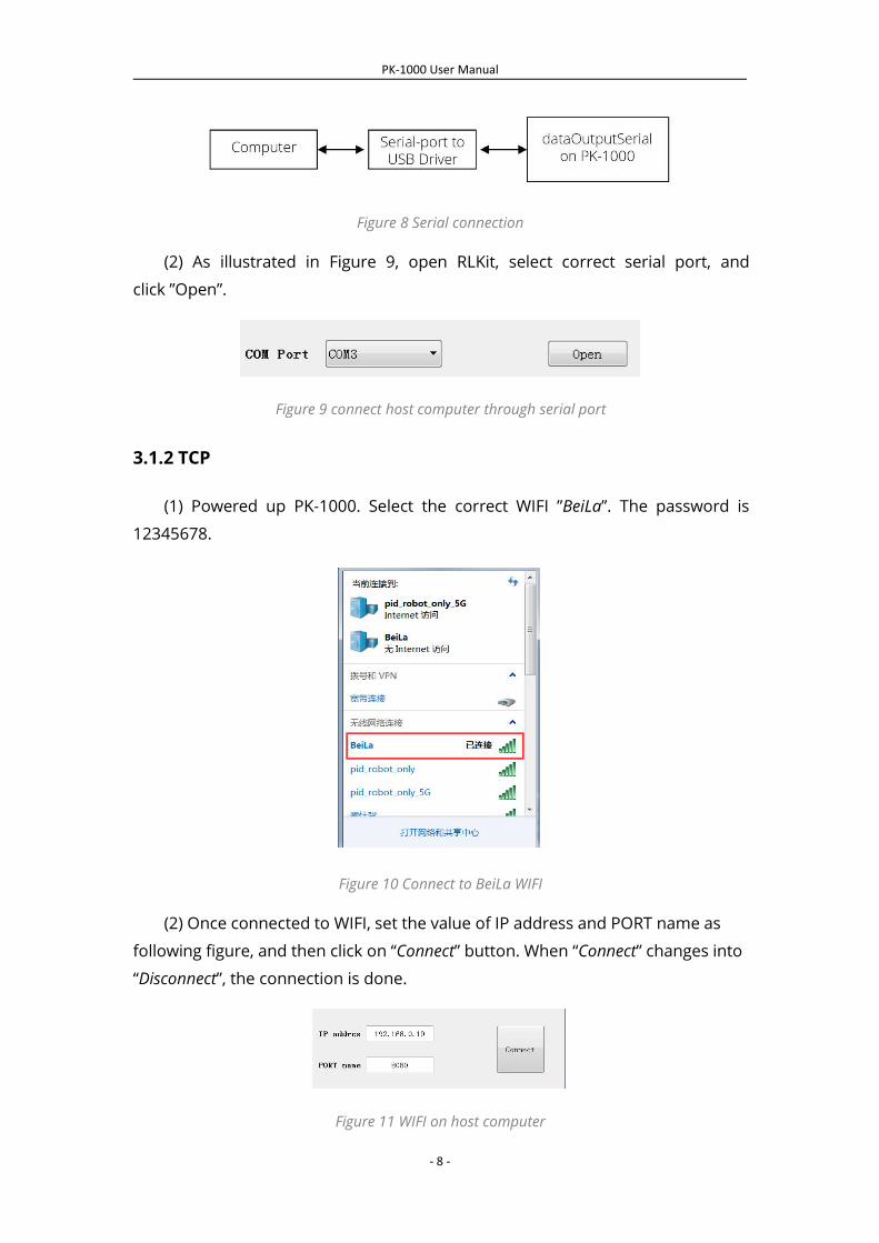
(2) Once connected to WIFI, set the value of IP address and PORT name as
following figure, and then click on “Connect” button. When “Connect” changes into
“Disconnect”, the connection is done.
Figure 11 WIFI on host computer
PK-1000 User Manual
- 9 -
(3) If connection failed, cut your WIFI and repeat step 1 and 2.
3.2 Set up information
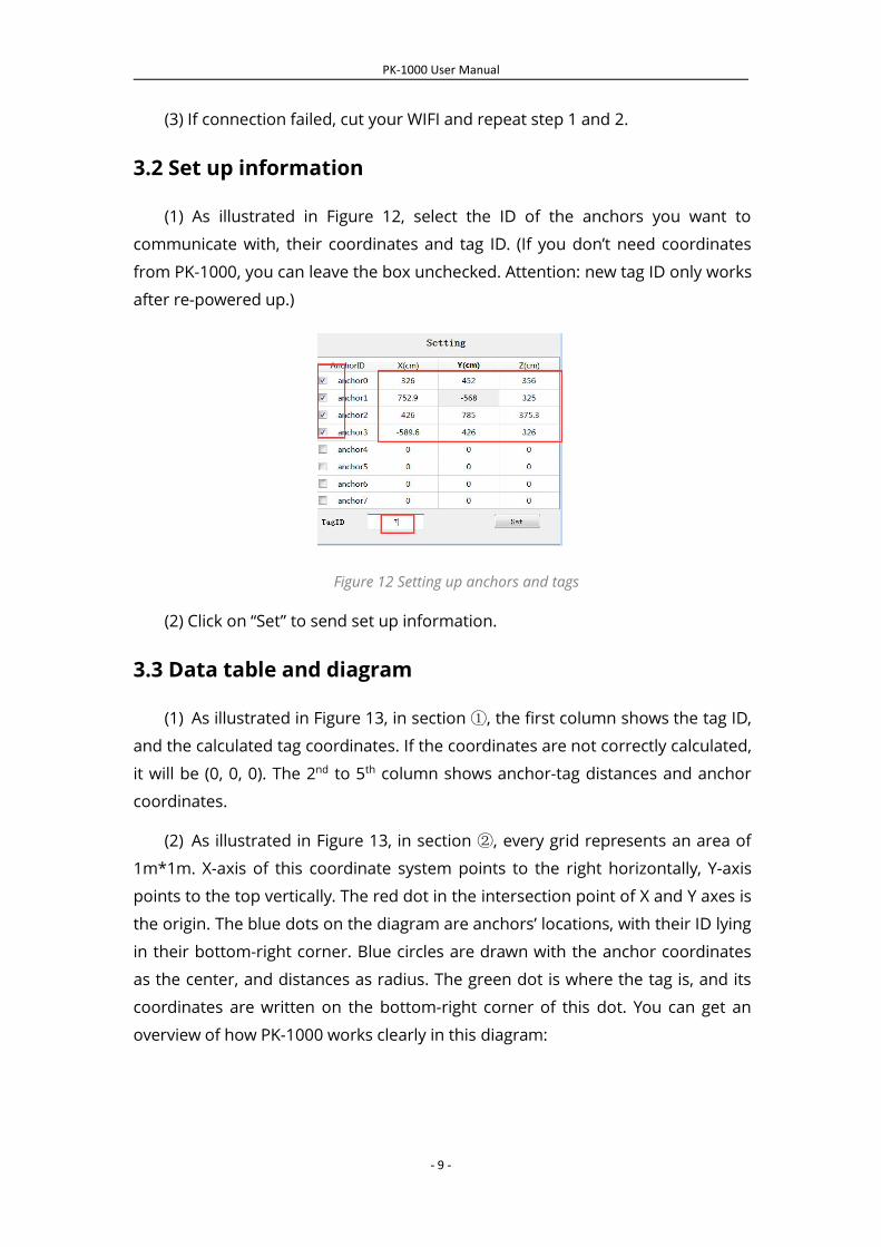
(1) As illustrated in Figure 12, select the ID of the anchors you want to
communicate with, their coordinates and tag ID. (If you don’t need coordinates
from PK-1000, you can leave the box unchecked. Attention: new tag ID only works
after re-powered up.)
Figure 12 Setting up anchors and tags
(2) Click on “Set” to send set up information.
3.3 Data table and diagram
(1) As illustrated in Figure 13, in section ①, the first column shows the tag ID,
and the calculated tag coordinates. If the coordinates are not correctly calculated,
it will be (0, 0, 0). The 2nd to 5th column shows anchor-tag distances and anchor
coordinates.
(2) As illustrated in Figure 13, in section ②, every grid represents an area of
1m*1m. X-axis of this coordinate system points to the right horizontally, Y-axis
points to the top vertically. The red dot in the intersection point of X and Y axes is
the origin. The blue dots on the diagram are anchors’ locations, with their ID lying
in their bottom-right corner. Blue circles are drawn with the anchor coordinates
as the center, and distances as radius. The green dot is where the tag is, and its
coordinates are written on the bottom-right corner of this dot. You can get an
overview of how PK-1000 works clearly in this diagram:

PK-1000 User Manual
- 10 -
Figure 13 Sample interface