pk-6 operation manual (revision e) pk-6/images/manuals/pk...pk-6 owners manual 1 introduction...
TRANSCRIPT
Owners Manual
© 2002 E-MU / ENSONIQ
All Rights Reserved
FI11859 Rev. E
E-MU World Headquarters Europe, Africa, Middle EastE-MU / ENSONIQ E-MU / ENSONIQ1600 Green Hills Road Suite 6, Adam Ferguson House
Scotts Valley, CA USA Eskmills Industrial Park
95066 Musselburgh, East Lothian
Telephone: 831-438-1921 Scotland, EH21 7PQ
Fax: 831-438-8612 Tel: +44 (0) 131-653-6556
Internet: www.emu.com Fax: +44 (0) 131-665-0473
Important Notice:In order to obtain warranty service on your PK-6 unit, the serial number sticker must be intact and you must have a sales receipt or other proof of purchase. If there is no serial number sticker on the PK-6, please contact E-MU Systems at once.
This product is covered under one or more of the following U.S. patents: 4,404,529; 4,506,579; 4,699,038; 4,987,600; 5,013,105; 5,072,645; 5,111,727; 5,144,676; 5,170,367; 5,248,845; 5,303,309; 5,317,104; 5,342,990; 5,430,244 and foreign patents and/or pending patents. All other trademarks belong to their respective companies. Specifications and features are subject to change without notice.
PK-6 Owners Manual i
Table of Contents
Introduction ............................................................................. 1Product Description .......................................................................................1
Important Safety Instructions .................................................. 3
Safety Instructions - German ................................................... 6
Safety Instructions - French ..................................................... 8
Setup ...................................................................................... 13Unpacking....................................................................................................13Connection Instructions..............................................................................14
Basic Setup ..............................................................................................14Performance Setup ..................................................................................15Studio Setup ............................................................................................16
Instant Gratification ............................................................... 19Playing Demo Sequences ........................................................................19Auditioning Presets .................................................................................20Selecting and Quick Editing Presets .......................................................20Exploring Beats Mode .............................................................................22Exploring the Master Arpeggiator ...........................................................24Multi-Channel Arpeggiator ....................................................................26
Time to Save? .......................................................................................28
Basic Operations .................................................................... 29Power Switch ...........................................................................................29Volume Control ......................................................................................29Channel +/- Buttons ...............................................................................29Data Entry Control .................................................................................29Cursor Buttons ........................................................................................30Pitch & Mod Wheels ...............................................................................30
ii E-MU Systems
Edit Section .................................................................................................. 30Global Button ......................................................................................... 30Controllers Button .................................................................................. 31Arp/Beats Button .................................................................................... 31MIDI Button ........................................................................................... 31MIDI Panic Button .................................................................................. 31Audition Button ...................................................................................... 31Compare Button ..................................................................................... 31Save/Copy Button ................................................................................... 32Preset Edit Button ................................................................................... 32Home/Enter Button ................................................................................ 32
Real-time Controller Knobs ......................................................................... 32Knob Functions ...................................................................................... 33
Quick Edit mode ................................................................................. 33Screen View Buttons .................................................................................... 34
Main ........................................................................................................ 34Multi ....................................................................................................... 34Mix Screen .............................................................................................. 34Demo Mode ............................................................................................ 35
Command Functions................................................................................... 36Preset Selection ....................................................................................... 36Trigger Mode ........................................................................................... 36Preset Menu Jump Keys .......................................................................... 36
Main Screen ................................................................................................. 37MIDI Channel Selection ......................................................................... 37Preset Selection ....................................................................................... 37Channel Volume .................................................................................... 38Channel Pan ........................................................................................... 39Channel Arpeggiator .............................................................................. 39
Sound Navigator .......................................................................................... 40Preset Category ....................................................................................... 40Instrument Category .............................................................................. 40
Multisetups .................................................................................................. 41Restoring Multisetups ............................................................................. 41Multisetup Name .................................................................................... 42Saving Multisetups ................................................................................. 42
Arp/Beats Menu ......................................................................43Beats ............................................................................................................. 44
Beats Mode .............................................................................................. 46Status ................................................................................................... 46Beats Channel ..................................................................................... 46Trigger Channel .................................................................................. 46
Beats Controllers ..................................................................................... 49Beat Velocity Group 1-4 ...................................................................... 49Beat Xpose Group 1-4 ......................................................................... 49Beat Busy ............................................................................................. 49Beat Variation ...................................................................................... 50
PK-6 Owners Manual iii
Beats Keys Layout ...................................................................................511-Bar Trigger Option ...........................................................................51
Beats Keys Offset .....................................................................................52Beats Part Velocity ..................................................................................52Beats Part Transpose ...............................................................................53Beats Part Group .....................................................................................54Master Riff ...............................................................................................54Riff Tempo ..............................................................................................55Riff Controllers .......................................................................................55MIDI Song Start ......................................................................................56Arp/Riff MIDI Out ...................................................................................56
Arpeggiators .................................................................................................57Arp Controllers .......................................................................................58
Arpeggiator Resolution ........................................................................58Arpeggiator Extension .........................................................................58Arpeggiator Velocity ............................................................................58Arpeggiator Gate...................................................................................58Arpeggiator Interval ............................................................................58
Master Arpeggiator Parameters ....................................................................58Status .......................................................................................................59Mode .......................................................................................................59Note Value ..............................................................................................60Arpeggiator Pattern Speed ......................................................................60Pattern .....................................................................................................60Velocity ...................................................................................................61Gate Time ................................................................................................61Extension Count .....................................................................................62Extension Interval ...................................................................................62Sync .........................................................................................................63Pre-Delay .................................................................................................63Duration ..................................................................................................64Post-Delay ...............................................................................................64Recycle ....................................................................................................65Keyboard Thru ........................................................................................65Latch .......................................................................................................65
Send MIDI System Exclusive Data ...............................................................66Editing a User Arpeggiator Pattern .........................................................67Pattern Step Number ...............................................................................67Key ..........................................................................................................67
Key Offset ............................................................................................68Tie ........................................................................................................68Rest ......................................................................................................68Skip ......................................................................................................68End .......................................................................................................68
Velocity ...................................................................................................69Duration ..................................................................................................69Repeat ......................................................................................................69User Pattern Name ..................................................................................70
Multichannel Arpeggiating..........................................................................70
iv E-MU Systems
Controllers Menu ....................................................................71Realtime Control Functions ........................................................................ 72
Keyboard Transpose ................................................................................ 72Keyboard Channel .................................................................................. 72Local Control On/Off ............................................................................. 72Keyboard Velocity Curve ........................................................................ 73Channel Aftertouch On/Off ................................................................... 74Footswitch Function ............................................................................... 74Foot Pedal Function ................................................................................ 75Trigger Buttons Function ........................................................................ 75Trigger Buttons ....................................................................................... 76
Trigger Button Select ........................................................................... 76Latch on/off ........................................................................................ 76MIDI Key ............................................................................................. 76MIDI Channel ..................................................................................... 76Velocity ............................................................................................... 76
Preset Select Buttons ............................................................................... 77Trigger Button Select ........................................................................... 77Preset Location .................................................................................... 77Preset Number ..................................................................................... 77Preset Name ......................................................................................... 77Category .............................................................................................. 77
Preset Select Send Buttons ...................................................................... 78Trigger Button Select ........................................................................... 78Bank MSB ............................................................................................ 78Program Change Number ................................................................... 78Bank LSB .............................................................................................. 78
Knob Preset Quick-Edit ........................................................................... 79Real-time Controller Assignment ........................................................... 79MIDI Footswitch Assign ......................................................................... 80Calibrate Controllers .............................................................................. 80Tempo Controller ................................................................................... 81Base Tempo ............................................................................................. 82
Global Menu ...........................................................................83Defining Global Parameters......................................................................... 84
Master Transpose/Tune .......................................................................... 84Master Bend Range ................................................................................. 84Master Velocity Curve ............................................................................ 85Mix Output ............................................................................................. 86
Master Effects ............................................................................................... 88Effects Mode ........................................................................................... 88Effects Multi Mode Control .................................................................... 88Master FXA Algorithm ............................................................................ 89
A Effect Types ...................................................................................... 89FXA Parameters: Decay/HF Damping FxB -> FxA .................................. 90FXA Send Amounts ................................................................................. 90Master FXB Algorithm ............................................................................ 90
B Effect Types ...................................................................................... 91
PK-6 Owners Manual v
FXB Parameters: Feedback/LFO Rate Delay Time ...................................91FXB Send Amounts .................................................................................91
Miscellaneous Parameters ............................................................................92Edit All Layers Enable .............................................................................92User Key Tuning .....................................................................................92Screen Viewing Angle .............................................................................92
MIDI Menu ............................................................................. 93Keyboard Outputs MIDI .........................................................................94Knobs Output MIDI ................................................................................94Transmit MIDI Clock ..............................................................................94MIDI Enable ............................................................................................94Receive Program Change ........................................................................95MIDI Program Change -> Preset .............................................................95MIDI SysEx ID .........................................................................................96MIDI SysEx Packet Delay ........................................................................97Send MIDI System Exclusive Data ..........................................................97MIDI Mode ..............................................................................................98
Omni ...................................................................................................98Poly ......................................................................................................98Multi ....................................................................................................98
Programming Basics .............................................................. 99Modulation ................................................................................................100Modulation Sources ...................................................................................101
Random Sources ....................................................................................102Modulation PatchCords.............................................................................102Envelope Generators ..................................................................................103
Tempo-based Envelopes ....................................................................104Envelope Repeat ................................................................................104
Low Frequency Oscillators (LFOs) .............................................................105Clock Modulation ......................................................................................106Modulation Destinations ...........................................................................108Modulation Processors ...............................................................................109Preset Modulation Processors ....................................................................111
Using the Modulation Processors .........................................................113More Examples ......................................................................................115
Dynamic Filters ..........................................................................................117What is a Filter? ....................................................................................118Parametric Filters ..................................................................................121The Z-Plane Filter ..................................................................................122
Signal Flow .................................................................................................123MIDI Channels & Real-time Controls .......................................................124
Bank Select Commands ........................................................................126Stereo Mix Outputs ....................................................................................127
vi E-MU Systems
Preset Edit Menu ..................................................................129Preset Name .......................................................................................... 130
Four Layer Architecture ............................................................................. 130Selecting Layers .................................................................................... 131
Defining Layer Parameters......................................................................... 132Selecting an Instrument ....................................................................... 132
Sound Navigator ............................................................................... 132Defining Key Range .............................................................................. 133Defining the Velocity Crossfade Range ................................................ 135Defining the Real-time Crossfade Range .............................................. 137Transposing the Instrument ................................................................. 140Tuning .................................................................................................. 141
Background: Transpose vs. Coarse Tuning ....................................... 141Amplifier ............................................................................................... 141Volume Envelope ................................................................................. 142
Selecting the Mode ............................................................................ 142Defining the Volume Envelope ........................................................ 143
Chorusing the Layer ............................................................................. 144Sound Start Offset and Delay ............................................................... 144Non-Transpose Mode ........................................................................... 145Solo Mode ............................................................................................. 145Assign Group ........................................................................................ 146Glide ..................................................................................................... 147Z-Plane Filters ....................................................................................... 148PK-6 Filter Types ................................................................................... 148
Filter Types ........................................................................................ 148Filter Parameters ................................................................................ 150
Filter Envelope ...................................................................................... 151Defining the Filter Envelope ............................................................. 152
Auxiliary Envelope ............................................................................... 152Low Frequency Oscillators (LFOs) ........................................................ 153
Shape ................................................................................................. 153Sync ................................................................................................... 154Rate .................................................................................................... 154Delay ................................................................................................. 156Variation ........................................................................................... 156
PatchCords ............................................................................................ 157Modulator Polarity ............................................................................ 158
Pitch Bend Range .................................................................................. 160Mix Output ........................................................................................... 160
Common Preset Parameters....................................................................... 161Preset Effects ......................................................................................... 161FXA Algorithm ...................................................................................... 163
A Effect Types .................................................................................... 163FXA Parameters ..................................................................................... 164FXA Send Amounts ............................................................................... 164FXB Algorithm ...................................................................................... 164
B Effect Types .................................................................................... 164FXB Parameters ..................................................................................... 165
PK-6 Owners Manual vii
FXB Send Amounts ...............................................................................165Preset Patchcords ..................................................................................165Initial Controller Amount ....................................................................167Keyboard Tuning ..................................................................................168Preset Links ...........................................................................................170Preset Tempo Offset ..............................................................................171Audition Riff Selection ..........................................................................171Play Solo Layers ....................................................................................171
Effects ................................................................................... 173Effects Overview.........................................................................................173
The Effects Sends ..................................................................................173Effect Types ................................................................................................175
Effect Parameters ...................................................................................175Decay .................................................................................................176High Frequency Damping .................................................................176Feedback ............................................................................................176LFO Rate ............................................................................................176Delay ..................................................................................................176
Effects Programmed in the Preset ..............................................................177Master Effects .............................................................................................178
Effects Mode ..........................................................................................180Flexible Effects Control .........................................................................180
Using the Effects Channel Settings in Multi Mode ..........................182Effect B Into Effect A .............................................................................182
General Effect Descriptions........................................................................184Reverb ...................................................................................................184Chorus ...................................................................................................185Doubling ...............................................................................................185Slapback ................................................................................................185Stereo Flanger ........................................................................................185Delay .....................................................................................................186Stereo Delay ..........................................................................................186Panning Delay .......................................................................................186Dual Tap ................................................................................................186Vibrato ..................................................................................................186Distortion ..............................................................................................186
Save/Copy Menu .................................................................. 187Saving a Preset ......................................................................................187
Copying Information.................................................................................188Copy Preset ...........................................................................................188Copy Layer ............................................................................................188Copy PatchCords ..................................................................................189Copy Preset PatchCords ........................................................................190Copy Arpeggiator Settings ....................................................................190Copy Arpeggiator Pattern .....................................................................191Copy Preset Bank ..................................................................................191
viii E-MU Systems
Sound Authoring ....................................................................................... 192Rename Flash SIMM ............................................................................. 193Duplicate Flash ..................................................................................... 194Create Random Preset .......................................................................... 195
Preset Programming .............................................................197Editing Presets............................................................................................ 197
Changing the Instrument .................................................................... 197Changing the Tuning of an Instrument .............................................. 198Chorus .................................................................................................. 199Volume Envelope ................................................................................. 199Working with Filters ............................................................................. 202
Adding the Filter Envelope ............................................................... 203Changing Filter Types ....................................................................... 205Envelope Repeat ................................................................................ 206
Practice Modulating .............................................................................. 206Troubleshooting ................................................................................... 207
Linking Presets ........................................................................................... 208
Appendix ...............................................................................209Front Panel Knob Functions...................................................................... 209
Knob Controller Descriptions .............................................................. 210Jam Presets ............................................................................................ 210
Preset Listing.............................................................................................. 211Instrument Listing ..................................................................................... 216Riff Listing.................................................................................................. 225Keyboard Velocity Curves.......................................................................... 229Master Velocity Curves .............................................................................. 232PatchCord Amount Chart ......................................................................... 234E-MU Expansion Sound Sets...................................................................... 235Installing Sound SIMMs............................................................................. 237MIDI........................................................................................................... 239
Received Channel Commands ............................................................. 246Technical Specifications............................................................................. 247Warranty .................................................................................................... 248
Index .....................................................................................251
PK-6 Owners Manual ix

x E-MU Systems
Introduction
Product Description
Upgradable SoundsPK-6 contains a new collection of presets designed for music composition in a wide variety of styles. These sounds are rich in harmonic texture and a perfect complement to the Z-plane filters. PK-6 contains three additional, user-upgradable sound SIMM sockets, allowing you to mix and match sound sets according to your needs. New sounds can be added as easily as plugging in a new 16MB or 32MB SIMM module. Each E-MU sound set has been meticulously crafted to be the finest of its kind. Samples are expertly matched across the keyboard and perfectly looped to create realistic instru-ments which form the exceptionally playable presets.
1024 Presets & morePK-6 contains 512 user presets and 512 factory ROM presets, but it can be expanded with literally thousands of ROM presets. (ROM presets are automatically added when sound SIMMs are installed. As an example, a 32 MB SIMM may contain up to 1024 ROM presets.) PK-6’s Sound Navigator makes it easy to find the exact sound you want. It’s powerful, yet simple to use.
Velocity & Pressure Sensitive KeyboardThe five-octave, velocity sensitive keyboard with aftertouch allows you to perform live or record via MIDI into an external computer/sequencer. The keyboard action is extremely responsive, capturing all the subtle nuances of your performance.
Multi-Function ControllersMulti-function buttons allow you to trigger arpeggiators and notes inter-nally or on any of your other MIDI devices. They can act as preset select buttons or Beats Mute or MIDI Trigger buttons (latched or unlatched).
Four real-time controller knobs are also multi-function controls. These knobs make it a snap to edit and modify internal preset parameters. The controllers are fully programmable and can control internal preset or other MIDI equipment. They can also be programmed to adjust multiple internal parameters at once, allowing complex levels of control. For example, a single knob can simultaneously turn up filter cutoff, while detuning one
PK-6 Owners Manual 1
IntroductionProduct Description
sample, and adjusting the release time of the volume envelope. Virtually every synth parameter in the PK-6 is controllable using the real-time knobs or by any internal or external control source.
SuperBeatsBeats Mode is a whole new way to create dynamic, original music. With Beats, you trigger, latch and unlatch synced loops and grooves from the sixteen trigger keys. Simply select a bts: preset and go. Then use PK-6’s perfomance controls to alter and mutate the rhythm or the sound itself.
Multi-Channel ArpeggiatorsPK-6’s Rhythmic Pattern Generator/Arpeggiator can play up to 16 synchro-nized arpeggiator patterns at once using a different sound for each! Patterns can be edited using pattern flow commands such as: delay for 2 bars, play for 4 bars, hold for 2 beats and repeat. You can program or download 100 user patterns in addition to the 200 factory patterns.
Ultra Powerful SynthesizerThe extremely flexible yet easy to use synthesizer makes it easy to build sounds of any kind. Up to 4 four layers can be switched or crossfaded using key position, velocity, real-time controllers or any modulation source. 64 voice polyphony ensures that you can play and sequence the most complex material. PK-6 also contains 50 different 2nd to 12th order resonant & modeling filters which are used to shape and modify over 1200 waveforms contained in 32 megabytes (MB) of ROM.
Sixty-four modulation sources include three multistage envelopes and two LFOs per layer, as well as full MIDI control over virtually every parameter. The digital patch bay, with 24 cords per layer, (and 12 more cords per preset) lets you connect modulation sources to 64 destinations in any imaginable way. The patch bay also contains a set of arithmetic modifiers, allowing you to create complex synthesis models. Synth parameters as well as arpeggiator and BEAT tempos can be controlled from PK-6’s internal clock (or an external MIDI clock). Up to 8 LFOs and 12 envelopes can be perfectly synchronized at different rates.
24-bit EffectsOnce you have created your preset, you can add richness to your sound using PK-6’s 24-bit stereo effects. You can choose a different effects setup for each preset from over 60 algorithms. PK-6’s effects section is actually two separate effects processors with control over each wet/dry mix level on four effects sends. Effects Processor “A” contains primarily ambiance algorithms like reverb and delays, while effects processor “B” contains primarily spectral algorithms such as chorus, flange, phase, distortion, and delay. Effects can be linked to each preset or used globally for increased flexibility.
Other features include multiple solo, voice assignment and performance modes for expressive control, 12 user-definable alternate tunings, and, of course, an extensive MIDI implementation.
2 E-MU Systems
Important Safety InstructionsGrounding Instructions
Important Safety Instructions
Use in countries other than the U.S.A. may require the use of a different line cord or attachment plug, or both. Refer all servicing to qualified service personnel. There are no user serviceable parts or adjustments inside the unit. There are no user serviceable parts inside the power supply enclosure.
WARNING: To reduce the risk of fire or electric shock, do not expose this product to rain or moisture.
Grounding Instructions
This product must be grounded. If it should malfunction or break down, grounding provides a path of least resistance for electric current, reducing the risk of electric shock. This product is equipped with a cord having an equipment-grounding conductor and a grounding plug. The plug must be plugged into an appropriate outlet properly installed and grounded in accordance with all local codes and ordinances.
Danger! Improper connection of the equipment’s grounding conductor can result in the risk of electric shock. Check with a qualified electrician or service personnel if you are in doubt as to whether the product is properly grounded. Do not modify the plug provided with this product. If it will not fit the outlet, have a proper outlet installed by a qualified technician.
UserMaintenance Instructions
1. The PK-6 (Model number 9725) should be kept clean and dust free. Periodically wipe the unit with a clean, dry, lint free cloth. Do not use solvents or cleaners.
2. There are no user lubrication or adjustment requirements.
Caution -Servicing instructions are for use by qualified personnel only. To reduce the risk of electric shock, do not perform any servicing other than that contained in these operating instructions unless you are qualified to do so. Refer all servicing to qualified service personnel.
INSTRUCTIONS PERTAINING TO A RISK OF FIRE, ELECTRIC SHOCK, OR INJURY TO PERSONS
PK-6 Owners Manual 3
Important Safety InstructionsUser Maintenance Instructions
READ THESE INSTRUCTIONS: When using electric products, basic precau-tions should always be adhered to, including the following:
1. Read all instructions before using PK-6.
2. Keep these instructions.
3. Heed all warnings.
4. Follow these instructions.
5. Do not use near water.
6. Clean only with a dry cloth.
7. Install in accordance with E-MU’s instructions. Do not block any openings. This apparatus should be situated so that its location or position does not interfere with proper ventilation. The ventilation should not be impeded by covering the ventilation openings with items such as newspapers, tablecloths, curtains, etc.
8. Do not install near any heat sources such as radiators, heat registers, stoves, or other apparatus (including amplifiers) which produce heat.
9. Do not defeat the safety purpose of the polarized or grounding-type plug. A polarized plug has two blades with one wider than the other. A grounding-type plug has two blades and a third grounding prong. The wide blade or the grounding prong are provided for your safety. If the provided plug does not fit into your outlet, consult an electrician for replacement of the obsolete outlet.
10. Protect the power cord from being walked on or pinched, particularly at plugs, convenience receptacles, and at the point where they exit from the apparatus.
11. Use only attachments/accessories specified by E-MU Systems.
12. Use only with the cart, stand, tripod, bracket, or table specified by E-MU or sold with the apparatus. When a cart is used, use caution when moving the cart/apparatus combination to avoid injury from tip-over.
13. Unplug the PK-6 from the power outlet during lightning storms or when left unused for a long period of time.
14. Refer all servicing to qualified service personnel. Servicing is required when the apparatus has been damaged in any way, such as power supply cord or plug is damaged, liquid has been spilled or objects have fallen into the apparatus, the apparatus has been exposed to rain or moisture, the does not operate normally or has been dropped.
15. No open flame sources, such as lit candles, should be placed on the apparatus.
16. The PK-6 is designed for use in moderate climates.
17. The apparatus shall not be exposed to dripping or splashing. No objects filled with liquids, such as vases, shall be placed on the apparatus.
18. To reduce the risk of injury, close supervision is necessary when using the apparatus near children.
19. The apparatus should be connected only to a power supply of the type described in the operating instructions and marked on the product.
This symbol is intended to alert you to the presence of important operating and maintenance (servicing)
instructions in the literature accompanying the unit.
This symbol is intended to alert you to the presence of
uninsulated dangerous voltage within the product’s
enclosure that may be of sufficient magnitude to
constitute a risk of electric shock to persons.
This symbol is intended to alert you to use caution when
moving a cart/apparatus combination to avoid injury.
4 E-MU Systems
Important Safety InstructionsRadio and Television Interference
20. This product, in combination with an amplifier and headphones and speakers, may be capable of producing sound levels that could cause permanent hearing loss. Do not operate for a long period of time at a high volume level or at a level that is uncomfortable. If you experience any hearing loss or ringing in the ears, consult an audiologist.
Radio and Television Interference
The equipment described in this manual generates and uses radio-frequency energy. If it is not installed and used properly —that is, in strict accordance with our instructions— it may cause interference with radio and television reception.
This equipment has been tested and complies with the limits for a Class B computing device in accordance with the specifications in Subpart J of Part 15 of the FCC rules. These rules are designed to provide reasonable protection against such interference in a residential installation. However, there is no guarantee that the interference will not occur in a particular installation, especially if a “rabbit ear” TV antenna is used.
If PK-6 does cause interference to radio or television reception, you can try to correct the interference by using one or more of the following measures:
• Turn the television or radio antenna until the interference stops.
• Move PK-6 to one side or the other of the television or radio.
• Move PK-6 farther away from the television or radio.
• Plug PK-6 into an outlet on a different circuit than the television or radio.
• Consider installing a rooftop antenna with a coaxial lead-in between the antenna and television set.
Copyright Information
It is the policy of E-MU / ENSONIQ to allow all users free, complete and unrestricted use to all of the presets, beats, riffs, patterns, and audition files contained in our products. However, we are unable to grant you a license to re-use, modify, create derivative works from, sell or redistribute the demon-stration files (demos). In most cases, these compositions are copyright protected by their respective authors and are licensed to E-MU / ENSONIQ for product demonstration purposes only. Please contact E-MU / ENSONIQ with additional questions.
PK-6 Owners Manual 5
Safety Instructions - GermanWichtige Sicherheitsvorschriften
Safety Instructions - German
Wichtige Sicherheits-vorschriften
In Ländern ausserhalb den U.S.A. können andere Kabel oder Stecker notwendig werden. Zur Verminderung des Risikos von Feuer oder eines elektrischen Schlages übergebe man den Service an qualifizierte Fachleute. Das Gerät niemals Regen oder Nässe aussetzen.
Erdungsin-struktionen
Das Gerät muss geerdet sein. Bei einem Defekt oder Ausfall bietet Erdung dem elektrischen Strom den Weg des geringsten Widerstandes und reduziert das Risiko eines Schlages. Dieses Gerät ist mit einem geerdeten Kabel und Stecker ausgerüstet. Der Stecker muss in eine passende, einwandfrei montierte und geerdete Steckdose in Übereinstimmung mit den örtlichen Vorschriften eingeführt werden.
Gefahr Unvorschriftsgemässer Anschluss des Gerätes kann zum Risiko eines elektrischen Schlages führen. Im Zweifelsfalle über die ordnungsgemässe Erdung soll ein qualifizierter Elektriker oder eine Serviecestelle beigezogen werden. Ändern Sie den mitgelieferten Stecker nicht. Sollte er nicht in die Steckdose passen, soll die einwandfreie Installation durch einen qualifi-zierten Techniker erfolgen.
Unterhaltsin-struktionen für anwender
1. PK-6 (Modell Nummer 9725) soll sauber und staubfrei gehalten werden. Das Gerät mit einem sauberen und säurefreien Tuch periodisch abreiben. Keine Lösungs- oder Reinigungsmittel anwenden.
2. Schmieren und Justieren sind nicht notwendig.
3. Bei weiteren Servicefragen wende man sich an eine qualifizierte Service-stelle.
Vorsicht Diese Gebrauchsanweisungen sind nur für qualifizierte Techniker beabsichtigt. Um die Gefahr eines elektrischen Schlages zu vermeiden, sollen Sie keine Arbeit unternehmen, die nicht in diesen Instruktionen vorgeschrieben ist. Wenden Sie Sich bei weiteren Servicefragen an eine qualifizierte Servicestelle.
6 E-MU Systems
Vorsicht
INSTRUKTIONEN BETR. FEUERRISIKO, ELEKTROSCHOCK ODER VERLETZUNG VON PERSONEN
WARNUNG; Beim Einsatz elektrischer Geräte sollten folgende Vorsichtsmassregeln stets beachtet werden:
1. Lesen Sie vor dem Einschalten des PK-6 alle Instruktionen.
2. Zur Vermeidung von Verletzungsrisiken müssen Kinder bei einge-schaltetem PK-6 sorgfältig überwacht werden.
3. PK-6 nicht in der Nähe von Wasser in Betrieb nehmen -- z.B. in der Nähe von Badewannen, Waschschüsseln, auf nassen Gestellen oder am Swimmingpool.
4. PK-6 stets so aufstellen, dass seine Belüftung nicht beeinträchtigt wird.
5. PK-6 nicht in der Nähe von Hitze aufstellen, wie Heizkörper, offenem Feuer, Öfen oder von Backöfen.
6. PK-6 ausschliesslich mit einem Netzgerät gemäss Bedienungsanleitung und Gerätemarkierung verwenden.
7. Dieses Gerät kann bei Verwendung von Kopfhörern und Verstärkern hohe Lautpegel erzeugen, welche zu bleibenden Gehörschäden führen. Arbeiten Sie nicht während längerer Zeit mit voller Lautstärke oder hohem Lautpegel. Stellen Sie Gehörverlust oder Ohrenläuten fest, wenden Sie sich an einen Ohrenartz.
8. PK-6 kann mit einem polarisierten Kabelstecker (mit ungleichen Stiften) ausgerüstet sein. Das geschieht für Ihre Sicherheit. Können Sie den Stecker nicht in die Steckdose einführen, ändern Sie nicht den Stecker ab, sondern wenden Sie sich an einen Elektriker.
9. Das Netzkabel des PK-6 bei längerem Nichtgebrauch aus der Steckdose ziehen.
10. Vermeiden Sie sorgfältig das Eindringen von Gegenständen oder Flüssigkeiten durch die Gehäuseöffnungen.
11. Das Gerät soll durch qualifizierte Serviceleute gewartet werden, falls:
A. das Netzkabel beschädigt wurde, oder
B. Gegenstände oder Flüssigkeit in das Gerät gelangten,
C. das Gerät Regen ausgesetzt war, oder
D. das Gerät nicht normal oder einwandfrei arbeitet, oder
E. das Gerät stürzte oder sein Gehäuse beschädigt wurde.
12. Servicearbeiten sollten nur qualifizierten Fachleuten anvertraut werden.
Dieses Symbol weist den Anwender auf wichtige Gebrauchs- und Service-
Vorschriften in den beilieg-enden Drucksachen.
Dieses Symbol verweist auf nicht-isolierte Stromspan-nungen im Geräte-Innern,
welche zu einem elektrischen Schlag führen könnten.
PK-6 Owners Manual 7
Safety Instructions - FrenchInstructions de Sécurité Importantes
Safety Instructions - French
Instructions de Sécurité Importantes
Une utilisation dans des pays autres que les U.S.A. peut nécessiter l’usage d’un cordon d’alimentation différent. Afin de réduire les risques d’incendie ou d’électrocution, référez-vous à un personnel de service qualifié, et n’exposez pas cet appareil à la pluie ou à l’humidité.
Instructions de Mise à la Terre
Cet appareil doit être relié à la terre. Dans le cas d’une malfonction éventuelle, la terre fournit un passage de moindre résistance pour le courant électrique, réduisant ainsi les risques d’électrocution. Le PK-6 est équipé d’un cordon muni d’un conducteur et d’une fiche devant être branchée dans une prise appropriée et reliée à la terre en conformité avec les normes locales.
Danger Une connexion incorrecte peut résulter en des risques d’électrocution. Vérifiez avec un technicien qualifié si vous avez des doutes quant à la connexion. Ne modifiez pas vous-même le cordon d’alimentation livré avec cet appareil; s’il ne rentre pas dans la prise, faites-en installer un autre par un technicien qualifié.
Instructions deMaintenance
1. Le PK-6 (Model 9725) doit être maintenu propre et sans poussière. Nettoyez-le périodiquement à l’aide d’un chiffon propre et non-pelucheux. N’utilisez pas de solvants, ou d’autres produits de nettoyage.
2. Aucune lubrification et aucun réglage ne sont nécessaires de votre part.
3. Pour tout autre service, référez-vous à un personnel qualifié.
Instructions Concernant les Risques d’Incendie, d’Electrocution, ou de Blessures Corporelles.
ATTENTION: Lorsque vous utilisez des appareils électriques, certaines précautions élémentaires doivent toujours être prises, incluant les suivantes:
8 E-MU Systems
Safety Instructions - FrenchInstructions de Maintenance
Ces instructions de dépanage sont destinées uniquement aux personnes qualifiées. Afin d’éviter les risques d’électrocution, n’effectuez que les opéra-tions décrites dans ce manuel, à moins que vous ne soyez qualifiê pour cela. Faites effectuer toute r’eparation par une personne qualifié.
1. Lisez bien toutes les instructions avant d’utiliser le PK-6.
2. Afin de réduire les risques de blessures, une attention particulière est nécessaire en la présence d’enfants en bas âge.
3. N’utilisez pas le PK-6 dans ou près d’endroits humides - par exemple près d’une baignoire, d’un lavabo, dans les toilettes, dans une cave humide, sur un bar fréquenté, en présence d’un bull-dog en rut, ou dans une piscine pleine. Protégez cet appareil de tout liquide, éclaboussure ou fuite.
4. Le PK-6 doit être placé de façon à ce que sa position n’interfére pas avec sa propre ventilation.
5. Le PK-6 doit être placé loin de sources de chaleur telles que des radia-teurs, cheminées, fours, ou groupies en chaleur.
6. Le PK-6 doit uniquement être connecté à une alimentation du type décrit dans les instructions d’opération et tel qu’indiqué sur l’appareil.
7. Une attention particulière doit être observée quant aux objets pouvant tomber et aux liquides pouvant être versés sur et à l’intérieur de le PK-6.
8. Le PK-6 peut être équipé d’une fiche secteur polarisée (avec une broche plus large que l’autre). C’est une mesure de sécurité. Si vous ne pouvez pas brancher cette fiche dans une prise, ne neutralisez pas cette sécurité. Contactez plutôt un électricien pour remplacer la prise obsolète.
9. Evitez de marcher sur le cordon d’alimentation ou de le coincer, particuliêrement prês des prises de courant, des boitiers ‘electriques dt du point de sortie de l’appareil.
10. Le cordon d’alimentation de le PK-6 doit être débranché lorsque ce dernier n’est pas utilisé pendant une longue période.
11. Cet appareil, combiné avec un amplificateur, des haut-parleurs, et/ou un casque, est capable de générer des niveaux sonores pouvant occasionner une perte de l’ouïe permanente. Ne travaillez pas trop longtemps à un volume trop élevé ou même inconfortable. Si vous observez une perte de l’audition ou un bourdonnement dans les oreilles, consultez un O.R.L.
12. N’utilisez que les accessoires sp’ecifi’es par E-MU Systems.
Ce symbole vous alerte de la présence d’instructions
importantes d’opération et de maintenance dans la notice accompagnant
l’appareil.
Ce symbole vous alerte de la présence d’un voltage non-isolé dangereux à l’intérieur de l’appareil,
pouvant être d’une magnitude suffisante pour
constituer un risque d’électrocution.
PK-6 Owners Manual 9

Safety Instructions - FrenchInterférences Radio et Télévision
13. Cet appareil doit être examiné par un personnel qualifié lorsque:
A. Le cordon d’alimentation a été endommagé, ou
B. Des objets sont tombés, ou du liquide a été versé sur/à l’intérieur de l’appareil, ou
C. Le PK-6 a été exposé à la pluie, ou
D. Le PK-6 est tombé, ou
E. Le PK-6 ne fonctionne pas normalement, ou affiche un changement radical de performance.
14. Tout service doit être effectué par un personnel qualifié.
SAUVEGARDEZ CES INSTRUCTIONS
Interférences Radio et Télévision
L’appareil décrit dans cette notice génére et utilise une énergie de fréquence-radio. S’il n’est pas installé et utilisé correctement - c’est à dire en suivant strictement nos instructions - il peut occasionner des interférences avec la réception d’une radio ou d’une télévision.
Cet appareil a été testé et est conforme aux normes de Classe A en accord avec les spécifications du paragraphe J de la section 15 des lois FCC. Ces lois sont désignées pour fournir une protection raisonnable contre de telles interférences dans une installation résidentielle. Toutefois, il n’est pas garanti qu’aucune interférence n’apparaisse dans des installations particulières, et plus spécialement lorsqu’une antenne de télévision en «oreilles de lapin» est utilisée.
Si le PK-6 occasionne des interférences , vous pouvez essayer de les corriger en utilisant une ou plusieurs des mesures suivantes:
• Tournez l’antenne de la télé ou de la radio jusqu’à ce que les inter-férences disparaissent.
• Déplacez le PK-6 d’un côté ou de l’autre de la télé ou de la radio.
• Eloignez le PK-6 de la télé ou de la radio.
• Branchez le PK-6 sur une prise différente que la télé ou la radio.
• Installez une antenne sur le toit munie d’une connexion coaxiale entre elle et le poste de télévision.
10 E-MU Systems
Declaration of Conformity
Declaration of Conformity
Manufacturer:E-MU / Ensoniq1600 Green Hills RoadScotts Valley, CA 95067-0015 USA
We hereby declare that the equipment listed herin conforms to the harmonized standards of the following European Commission Directives: 89/336/EEC and 72/23/EEC.
Trade Name: PK-6
Model Number: 9725
Under 89/336/EEC as amended by 92/31/EEC, and 93/68/EEC
In accordance with EN 55103-1:1996, Emission Environments E4
In accordance with EN 55103-2:1996, Immunity Environments E4
Test information is contained in a report by Atlas Compliance and Engineering, Inc.
Dated July 5, 2001
Report No.: 0126EMUx17_103
Under 73/23/EEC as amended by 93/68/EEC
In accordance with EN 60950 with amendments A1, A2, A3, A4, A11
This Declaration is made July 5, 2001
PK-6 Owners Manual 11

Safety Instructions - French
12 E-MU Systems
Setup
This section thoroughly describes how to set up your new PK-6 for use. Setup includes unpacking instructions, how to hook up the unit to your sound system and, most importantly, how to turn the thing on and off.
Unpacking Carefully remove PK-6 from the packaging material. Take care to save the packing materials in case you need to transport the unit. Check to make sure all components are included and in good condition. If there are missing or damaged components, contact E-MU Systems immediately for replacement or repair.
The PK-6 box should include the following components:
• PK-6 unit
• Power cable
• This owners manual
PK-6 Owners Manual 13
SetupBasic Setup
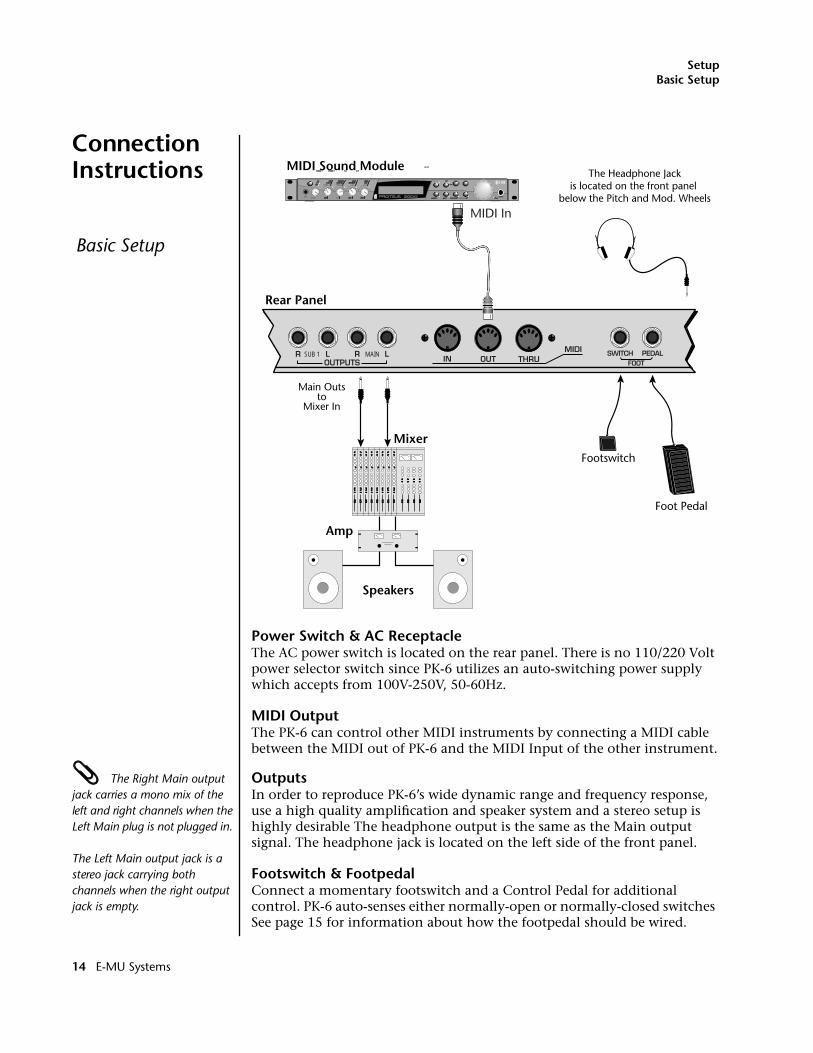
Connection Instructions
Power Switch & AC ReceptacleThe AC power switch is located on the rear panel. There is no 110/220 Volt power selector switch since PK-6 utilizes an auto-switching power supply which accepts from 100V-250V, 50-60Hz.
MIDI OutputThe PK-6 can control other MIDI instruments by connecting a MIDI cable between the MIDI out of PK-6 and the MIDI Input of the other instrument.
The Right Main output jack carries a mono mix of the left and right channels when the Left Main plug is not plugged in.
The Left Main output jack is a stereo jack carrying both channels when the right output jack is empty.
OutputsIn order to reproduce PK-6’s wide dynamic range and frequency response, use a high quality amplification and speaker system and a stereo setup is highly desirable The headphone output is the same as the Main output signal. The headphone jack is located on the left side of the front panel.
Footswitch & FootpedalConnect a momentary footswitch and a Control Pedal for additional control. PK-6 auto-senses either normally-open or normally-closed switches See page 15 for information about how the footpedal should be wired.
Basic Setup
Rear Panel
R L R LIN OUT THRUOUTPUTS
MIDI SWITCH PEDALSUB 1 MAINFOOT
Main Outsto
Mixer In
The Headphone Jackis located on the front panel
below the Pitch and Mod. Wheels
Speakers
Amp
Mixer
MIDI In
MIDI Sound Module
Footswitch
Foot Pedal
A/E/IVOLUME
VOLUME
B/F/J
B/F/J
C/G/K D/H/L AUDITION MULTI SAVE/COPY HOME/ENTER
HOME/ENTER
MIDIPOWER
TONEATTACK
DYNAMIC 1
DYNAMIC 1
A-DE-H
ARP
PRESENCEDECAY/RLS
DYNAMIC 2
DYNAMIC 2
SHAPEMOVEMENT
FX A
FX A
IMAGERATE
FX B
FX B
MASTER
MASTER
EDIT
14 E-MU Systems
SetupPerformance Setup
Performance Setup
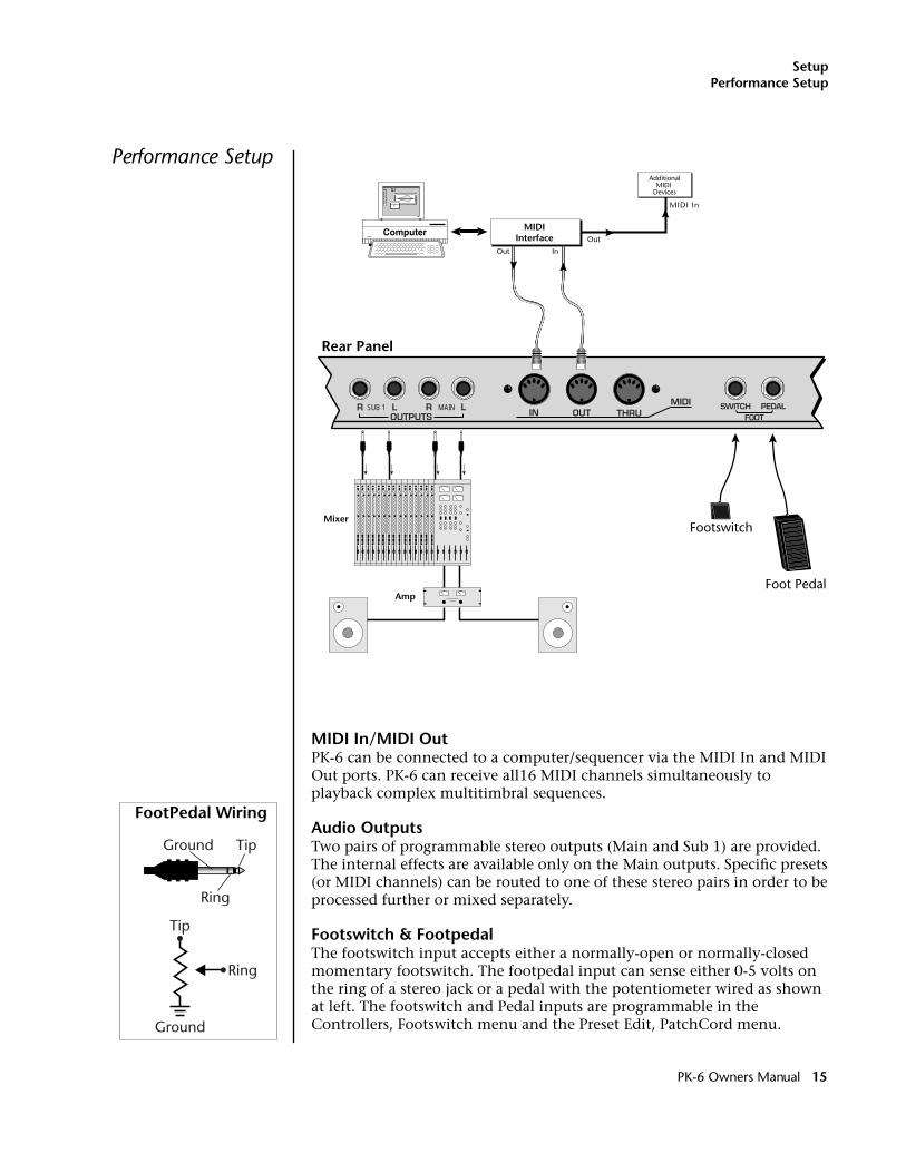
MIDI In/MIDI OutPK-6 can be connected to a computer/sequencer via the MIDI In and MIDI Out ports. PK-6 can receive all16 MIDI channels simultaneously to playback complex multitimbral sequences.
Audio OutputsTwo pairs of programmable stereo outputs (Main and Sub 1) are provided. The internal effects are available only on the Main outputs. Specific presets (or MIDI channels) can be routed to one of these stereo pairs in order to be processed further or mixed separately.
Footswitch & FootpedalThe footswitch input accepts either a normally-open or normally-closed momentary footswitch. The footpedal input can sense either 0-5 volts on the ring of a stereo jack or a pedal with the potentiometer wired as shown at left. The footswitch and Pedal inputs are programmable in the Controllers, Footswitch menu and the Preset Edit, PatchCord menu.
Rear Panel
R L R LIN OUT THRUOUTPUTS
MIDI SWITCH PEDALSUB 1 MAINFOOT
Amp
Mixer
MIDI In
AdditionalMIDI
Devices
MIDIInterface
Out In
OutComputer
Footswitch
Foot Pedal
Ground Tip
Ring
Ground
Tip
Ring
FootPedal Wiring
PK-6 Owners Manual 15
SetupStudio Setup
Studio Setup
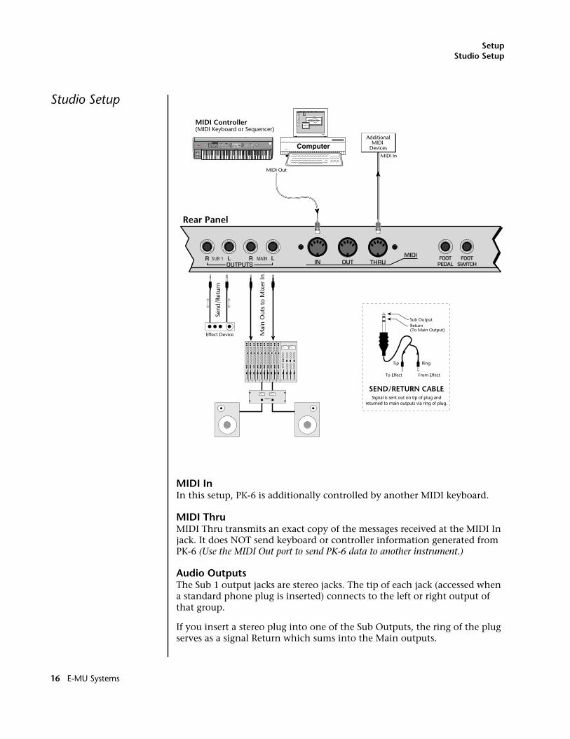
MIDI InIn this setup, PK-6 is additionally controlled by another MIDI keyboard.
MIDI ThruMIDI Thru transmits an exact copy of the messages received at the MIDI In jack. It does NOT send keyboard or controller information generated from PK-6 (Use the MIDI Out port to send PK-6 data to another instrument.)
Audio OutputsThe Sub 1 output jacks are stereo jacks. The tip of each jack (accessed when a standard phone plug is inserted) connects to the left or right output of that group.
If you insert a stereo plug into one of the Sub Outputs, the ring of the plug serves as a signal Return which sums into the Main outputs.
Rear Panel
R L R LIN OUT THRUOUTPUTS
MIDI FOOTSWITCH
FOOTPEDAL
SUB 1 MAIN
Sub OutputReturn(To Main Output)
Tip Ring
To Effect From Effect
SEND/RETURN CABLE
Send
/Ret
urn
Mai
n O
uts
to M
ixer
In
Effect Device
AdditionalMIDI
Devices
MIDI Controller(MIDI Keyboard or Sequencer)
MIDI Out
MIDI In
Signal is sent out on tip of plug andreturned to main outputs via ring of plug.
EMULATOR
P R E S E T
S A M P L E
S E Q U E N C E R
P A G E
L E V E L
P R E S E T S E L E C T
R E A L T I M E C O N T R O L L E R SA S S I G N A B L E K E Y S
E N T E RE X I T
R E T U R N
0 .987654321 Computer
16 E-MU Systems
SetupStudio Setup
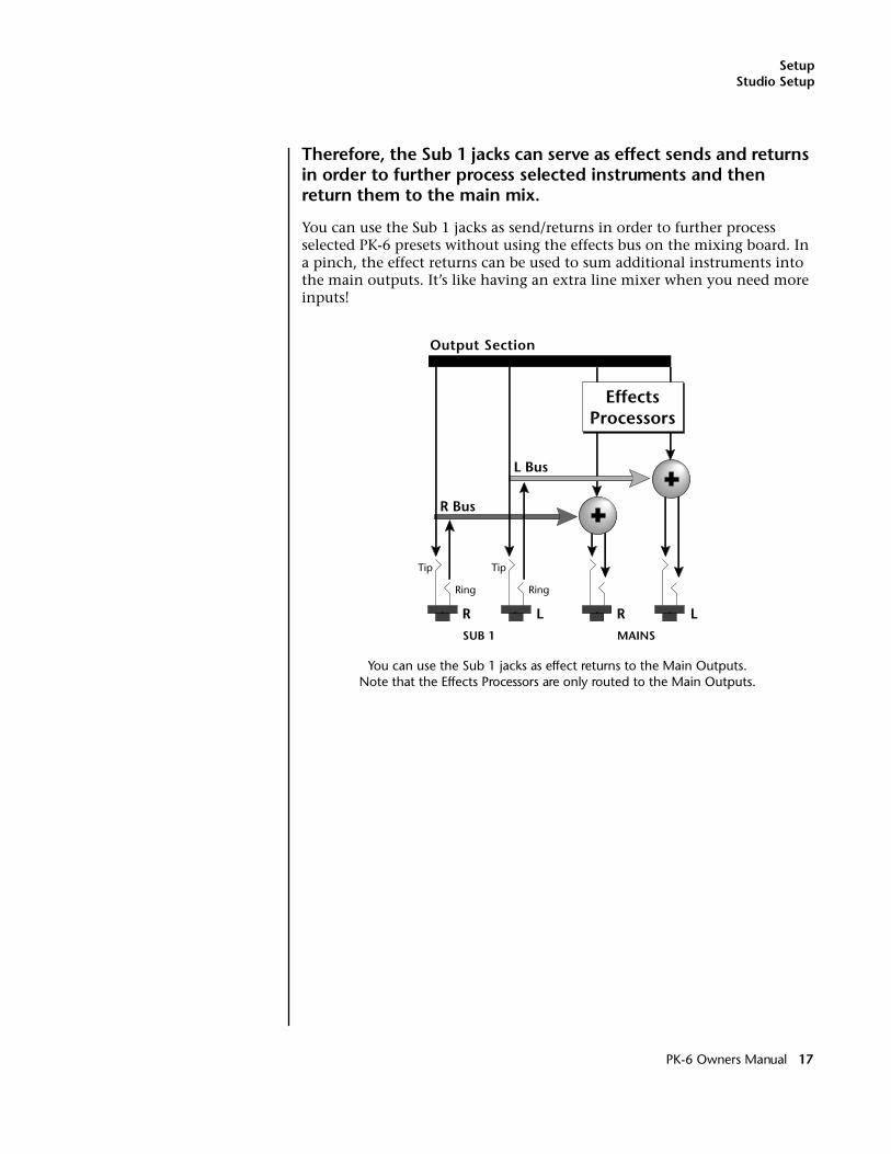
Therefore, the Sub 1 jacks can serve as effect sends and returns in order to further process selected instruments and then return them to the main mix.
You can use the Sub 1 jacks as send/returns in order to further process selected PK-6 presets without using the effects bus on the mixing board. In a pinch, the effect returns can be used to sum additional instruments into the main outputs. It’s like having an extra line mixer when you need more inputs!
You can use the Sub 1 jacks as effect returns to the Main Outputs. Note that the Effects Processors are only routed to the Main Outputs.
MAINS
R L
R Bus
L Bus
Output Section
Tip
Ring
Tip
Ring
SUB 1
R L
EffectsProcessors
PK-6 Owners Manual 17
SetupStudio Setup
18 E-MU Systems
Instant Gratification
This section presents step-by-step instructions for the most fundamental operations to get you up and running as quickly as possible.
Playing Demo Sequences
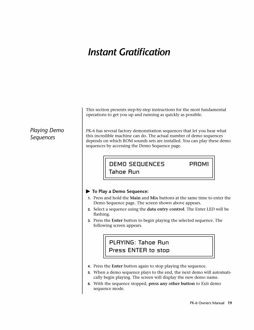
PK-6 has several factory demonstration sequences that let you hear what this incredible machine can do. The actual number of demo sequences depends on which ROM sounds sets are installed. You can play these demo sequences by accessing the Demo Sequence page.
� To Play a Demo Sequence:1. Press and hold the Main and Mix buttons at the same time to enter the
Demo Sequence page. The screen shown above appears.
2. Select a sequence using the data entry control. The Enter LED will be flashing.
3. Press the Enter button to begin playing the selected sequence. The following screen appears.
4. Press the Enter button again to stop playing the sequence.
5. When a demo sequence plays to the end, the next demo will automati-cally begin playing. The screen will display the new demo name.
6. With the sequence stopped, press any other button to Exit demo sequence mode.
DEMO SEQUENCES PROM1Tahoe Run
PLAYING: Tahoe RunPress ENTER to stop
PK-6 Owners Manual 19
Instant GratificationAuditioning Presets
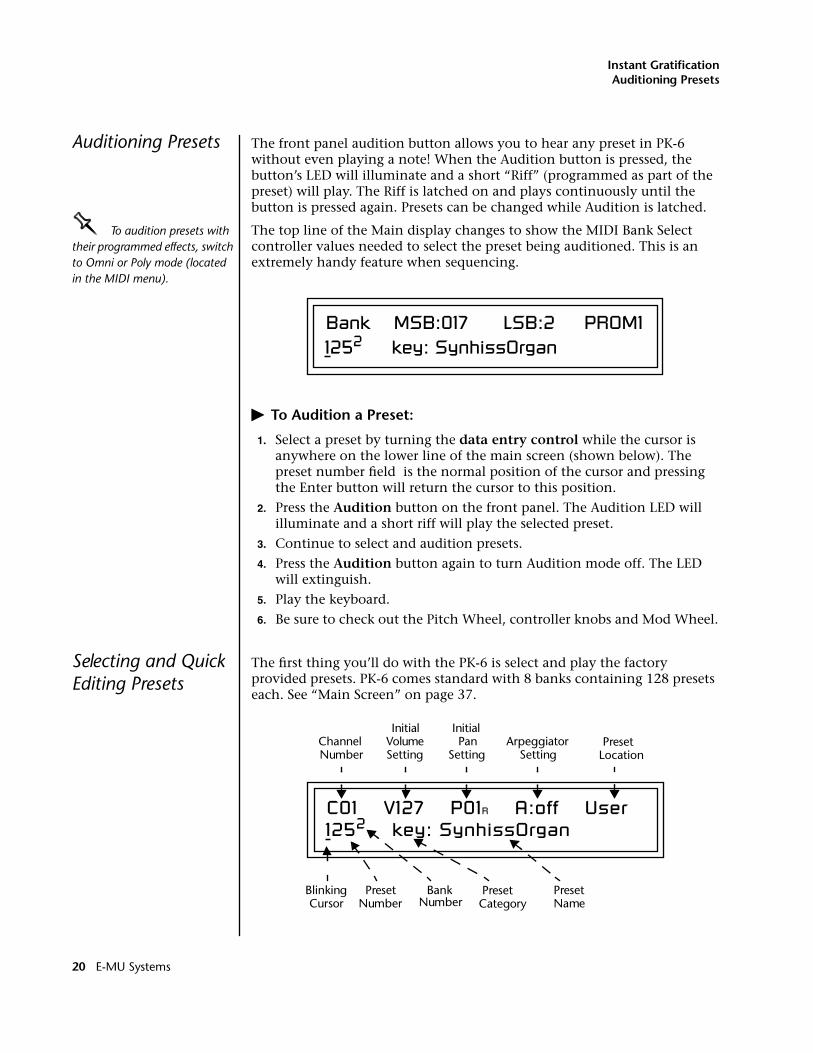
Auditioning Presets The front panel audition button allows you to hear any preset in PK-6 without even playing a note! When the Audition button is pressed, the button’s LED will illuminate and a short “Riff” (programmed as part of the preset) will play. The Riff is latched on and plays continuously until the button is pressed again. Presets can be changed while Audition is latched.
OOOO To audition presets with their programmed effects, switch to Omni or Poly mode (located in the MIDI menu).
The top line of the Main display changes to show the MIDI Bank Select controller values needed to select the preset being auditioned. This is an extremely handy feature when sequencing.
� To Audition a Preset:
1. Select a preset by turning the data entry control while the cursor is anywhere on the lower line of the main screen (shown below). The preset number field is the normal position of the cursor and pressing the Enter button will return the cursor to this position.
2. Press the Audition button on the front panel. The Audition LED will illuminate and a short riff will play the selected preset.
3. Continue to select and audition presets.
4. Press the Audition button again to turn Audition mode off. The LED will extinguish.
5. Play the keyboard.
6. Be sure to check out the Pitch Wheel, controller knobs and Mod Wheel.
Selecting and Quick Editing Presets
The first thing you’ll do with the PK-6 is select and play the factory provided presets. PK-6 comes standard with 8 banks containing 128 presets each. See “Main Screen” on page 37.
Bank MSB:017 LSB:2 PROM11252 key: SynhissOrgan
C01 V127 P01R A:off User1252 key: SynhissOrgan
PresetNumber
BankNumber
ChannelNumber
Initial VolumeSetting
Initial PanSetting
ArpeggiatorSetting
BlinkingCursor
PresetName
PresetLocation
PresetCategory
20 E-MU Systems
Instant GratificationSelecting and Quick Editing Presets
The first four banks are USER locations that can be overwritten and used to store your own presets. The presets that come stored in the USER presets are duplicated in banks 0-3 of the “PK-6” ROM bank, so feel free to overwrite them with your own presets. You won’t be losing anything.
The ROM Card identifier is shown in the top right of the display. The preset is identified in the bottom line of the main screen (the screen that appears when you press the Mode/View Preset button).
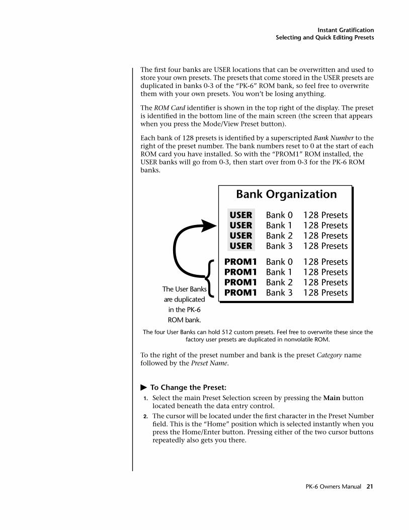
Each bank of 128 presets is identified by a superscripted Bank Number to the right of the preset number. The bank numbers reset to 0 at the start of each ROM card you have installed. So with the “PROM1” ROM installed, the USER banks will go from 0-3, then start over from 0-3 for the PK-6 ROM banks.
The four User Banks can hold 512 custom presets. Feel free to overwrite these since the factory user presets are duplicated in nonvolatile ROM.
To the right of the preset number and bank is the preset Category name followed by the Preset Name.
� To Change the Preset:1. Select the main Preset Selection screen by pressing the Main button
located beneath the data entry control.
2. The cursor will be located under the first character in the Preset Number field. This is the “Home” position which is selected instantly when you press the Home/Enter button. Pressing either of the two cursor buttons repeatedly also gets you there.
PROM1PROM1PROM1PROM1
Bank 0Bank 1Bank 2Bank 3
Bank 0Bank 1Bank 2Bank 3
128 Presets128 Presets128 Presets128 Presets
128 Presets128 Presets128 Presets128 Presets
}
USERUSERUSERUSER
Bank Organization
The User Banksare duplicated
in the PK-6ROM bank.
PK-6 Owners Manual 21
Instant GratificationExploring Beats Mode
OOOO You can select presets from the Preset Number, Bank Number, Preset Category or Preset Name fields.
3. Turn the data entry control knob on the front panel to select a new preset number. If you turn the knob slowly, the presets advance one number for each “click” of the knob. If you spin the knob quickly, the numbers advance much faster (more than one number per click).
4. Play the keyboard (or press the Audition button) and listen to the sounds made by your PK-6!
5. TRY OUT ANY OF THE CONTROLLER KNOBS on the front panel and note how they change the sound of each preset! Don’t worry about ruining the sound, the values are automatically reset as soon as you select a new preset. The four buttons labeled A-D, E-H, I-L, M-P allow the four controller knobs to control sixteen functions.
Exploring Beats Mode
PK-6 contains a 16-track play-only sequencer that is optimized for live performance and groove creation. PK-6 contains dozens of special 16-part Beats Riffs. Beats Riffs are normally used in conjunction with a “bts:” preset containing the appropriate percussion mapping. Before you start exploring beats, make sure the PK-6 is properly set up.
� Beats Setup:
Set the Trigger Buttons to Beats Mode
1. Press the Controllers button on the front panel.
2. Turn the data entry control clockwise until you fin the “TRIGGER BUTTONS FUNCTION” screen.
3. Set the lower line of the display to read, “Play Beats Parts”.
4. Press the Controllers button on the front panel again to exit the menu.
Set the Trigger Buttons to be Triggers
5. Press the Triggers button in the Command Functions section of the front panel. OK, now you’re ready to start playing Beats.
� Playing Beats:
Selecting Beats Presets____ If you don’t select a “bts:” preset, only the first trigger key will work.
Riffs marked “bts:” have 16 parts. Riffs without “bts:” have only 1 part.
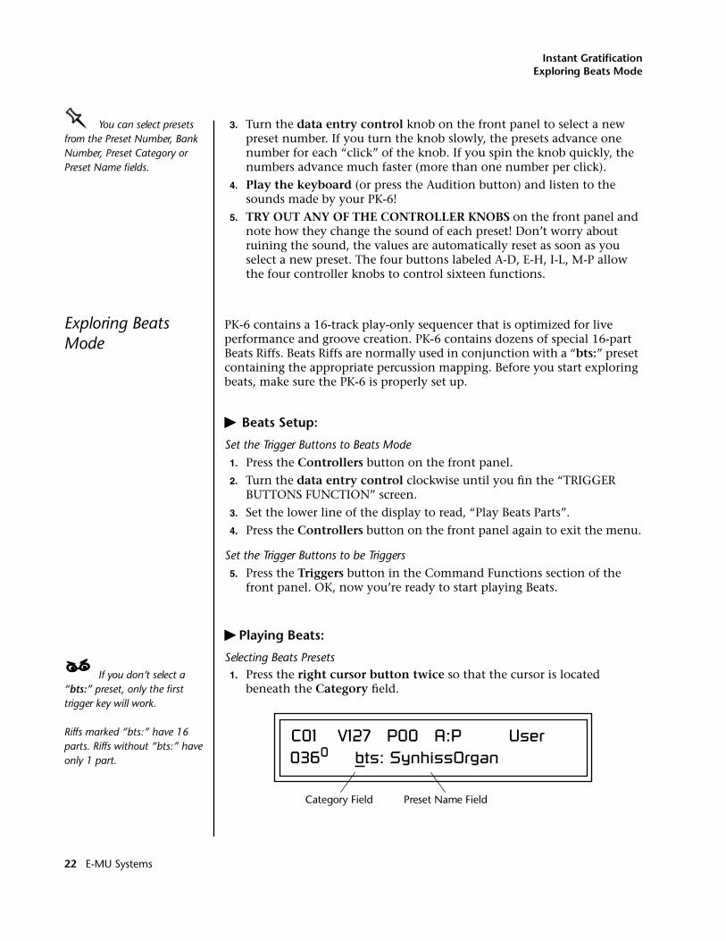
1. Press the right cursor button twice so that the cursor is located beneath the Category field.
C01 V127 P00 A:P User0360 bts: SynhissOrgan
Category Field Preset Name Field
22 E-MU Systems
Instant GratificationExploring Beats Mode
2. Turn the data entry control until bts: is shown in the Category field.
3. Press the right cursor button so that the cursor is underneath the Preset Name field.
4. Now turning the data entry control selects ONLY bts: presets!
Play Beats
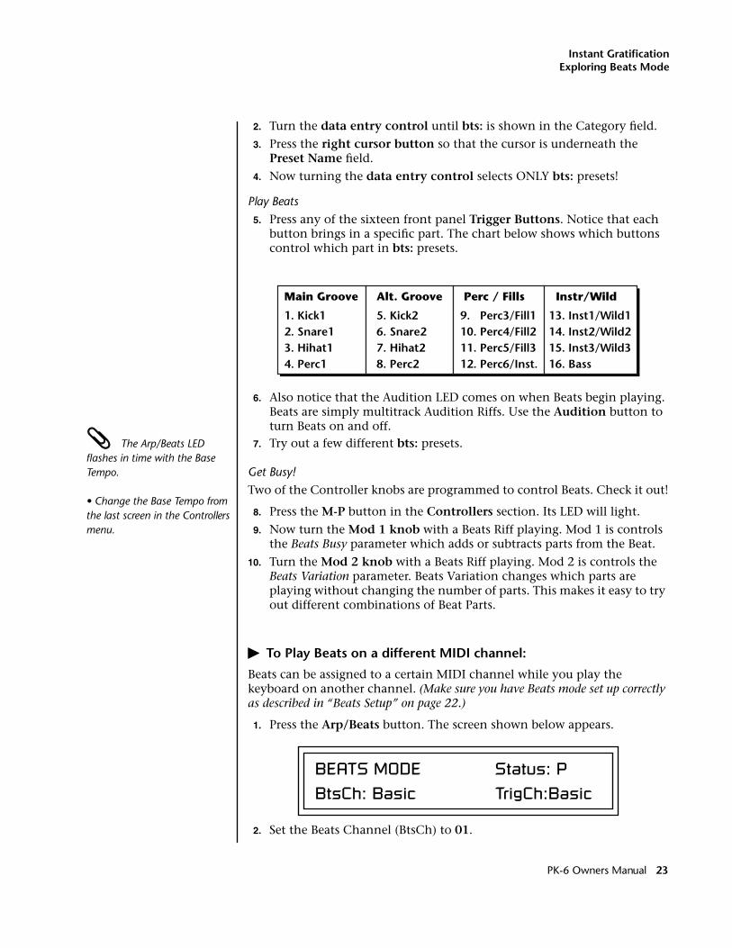
5. Press any of the sixteen front panel Trigger Buttons. Notice that each button brings in a specific part. The chart below shows which buttons control which part in bts: presets.
6. Also notice that the Audition LED comes on when Beats begin playing. Beats are simply multitrack Audition Riffs. Use the Audition button to turn Beats on and off.
The Arp/Beats LED flashes in time with the Base Tempo.
• Change the Base Tempo from the last screen in the Controllers menu.
7. Try out a few different bts: presets.
Get Busy!
Two of the Controller knobs are programmed to control Beats. Check it out!
8. Press the M-P button in the Controllers section. Its LED will light.
9. Now turn the Mod 1 knob with a Beats Riff playing. Mod 1 is controls the Beats Busy parameter which adds or subtracts parts from the Beat.
10. Turn the Mod 2 knob with a Beats Riff playing. Mod 2 is controls the Beats Variation parameter. Beats Variation changes which parts are playing without changing the number of parts. This makes it easy to try out different combinations of Beat Parts.
� To Play Beats on a different MIDI channel:
Beats can be assigned to a certain MIDI channel while you play the keyboard on another channel. (Make sure you have Beats mode set up correctly as described in “Beats Setup” on page 22.)
1. Press the Arp/Beats button. The screen shown below appears.
2. Set the Beats Channel (BtsCh) to 01.
Alt. Groove
5. Kick2 6. Snare2 7. Hihat2 8. Perc2
Perc / Fills
9. Perc3/Fill1 10. Perc4/Fill2 11. Perc5/Fill3 12. Perc6/Inst.
Instr/Wild
13. Inst1/Wild1 14. Inst2/Wild2 15. Inst3/Wild3 16. Bass
Main Groove
1. Kick1 2. Snare1 3. Hihat1 4. Perc1
BEATS MODE Status: PBtsCh: Basic TrigCh:Basic
PK-6 Owners Manual 23
Instant GratificationExploring the Master Arpeggiator
3. Select any bts: preset on channel 1 (main screen).
4. Press any of the sixteen Beats buttons to start your Beat playing. (Do NOT start Beats by pressing the Audition button.)
OOOO Wrong FX? In Omni mode, the FX assigned to channel 2 will be used. In Multi mode, the Master FX settings will be used. See pages 88 & 98.
5. Press the + Channel button to the left of the LCD to select channel 2.
6. Select a preset to jam along with the Beat.
7. The Trigger Keys now play Beats and the other keys play the preset on channel 2.
8. The Audition button can be used to turn the Beat off. (If you try to use it to turn Beats on while on channel 2, the Riff on channel 2 will play.)
Exploring the Master Arpeggiator
PK-6’s multi-channel Pattern Generator/Arpeggiator is one of the greatest features ever put in a synth. Let’s explore the Master Arpeggiator.
� To Arpeggiate a Single Preset:
1. Select a preset. Note that the factory presets all have prefixes which describe the type of sound. For this investigation it might be best to choose a preset with the prefix “arp,” for arpeggiator. These presets are optimized for use with the arpeggiator.
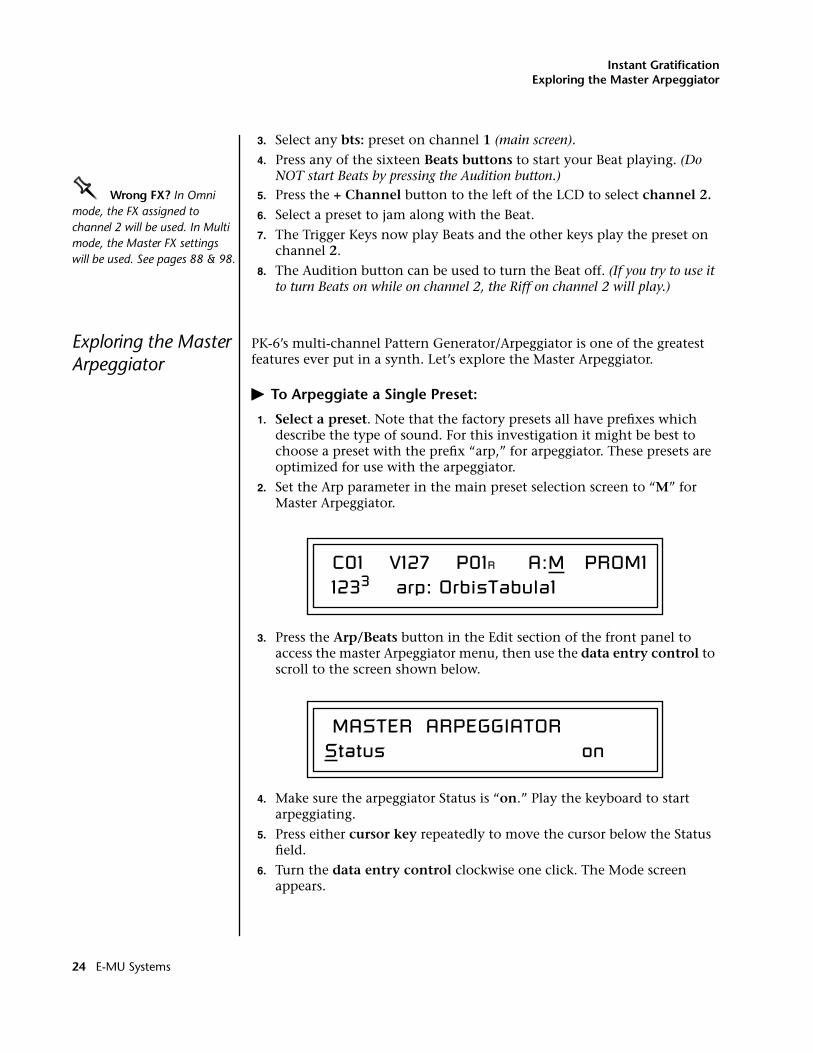
2. Set the Arp parameter in the main preset selection screen to “M” for Master Arpeggiator.
3. Press the Arp/Beats button in the Edit section of the front panel to access the master Arpeggiator menu, then use the data entry control to scroll to the screen shown below.
4. Make sure the arpeggiator Status is “on.” Play the keyboard to start arpeggiating.
5. Press either cursor key repeatedly to move the cursor below the Status field.
6. Turn the data entry control clockwise one click. The Mode screen appears.
C01 V127 P01R A:M PROM1 1233 arp: OrbisTabula1
MASTER ARPEGGIATORStatus on
24 E-MU Systems
Instant GratificationExploring the Master Arpeggiator
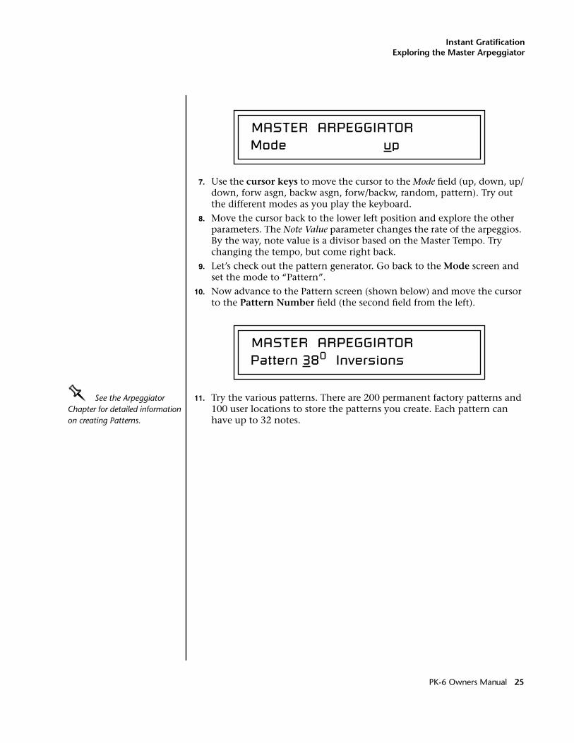
7. Use the cursor keys to move the cursor to the Mode field (up, down, up/down, forw asgn, backw asgn, forw/backw, random, pattern). Try out the different modes as you play the keyboard.
8. Move the cursor back to the lower left position and explore the other parameters. The Note Value parameter changes the rate of the arpeggios. By the way, note value is a divisor based on the Master Tempo. Try changing the tempo, but come right back.
9. Let’s check out the pattern generator. Go back to the Mode screen and set the mode to “Pattern”.
10. Now advance to the Pattern screen (shown below) and move the cursor to the Pattern Number field (the second field from the left).
OOOO See the Arpeggiator Chapter for detailed information on creating Patterns.
11. Try the various patterns. There are 200 permanent factory patterns and 100 user locations to store the patterns you create. Each pattern can have up to 32 notes.
MASTER ARPEGGIATOR Mode up
MASTER ARPEGGIATOR Pattern 380 Inversions
PK-6 Owners Manual 25
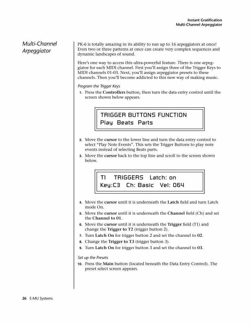
Instant GratificationMulti-Channel Arpeggiator
Multi-Channel Arpeggiator
PK-6 is totally amazing in its ability to run up to 16 arpeggiators at once! Even two or three patterns at once can create very complex sequences and dynamic landscapes of sound.
Here’s one way to access this ultra-powerful feature. There is one arpeg-giator for each MIDI channel. First you’ll assign three of the Trigger Keys to MIDI channels 01-03. Next, you’ll assign arpeggiator presets to these channels. Then you’ll become addicted to this new way of making music.
Program the Trigger Keys
1. Press the Controllers button, then turn the data entry control until the screen shown below appears.
2. Move the cursor to the lower line and turn the data entry control to select “Play Note Events”. This sets the Trigger Buttons to play note events instead of selecting Beats parts.
3. Move the cursor back to the top line and scroll to the screen shown below.
4. Move the cursor until it is underneath the Latch field and turn Latch mode On.
5. Move the cursor until it is underneath the Channel field (Ch) and set the Channel to 01.
6. Move the cursor until it is underneath the Trigger field (T1) and change the Trigger to T2 (trigger button 2).
7. Turn Latch On for trigger button 2 and set the channel to 02.
8. Change the Trigger to T3 (trigger button 3).
9. Turn Latch On for trigger button 3 and set the channel to 03.
Set up the Presets
10. Press the Main button (located beneath the Data Entry Control). The preset select screen appears.
TRIGGER BUTTONS FUNCTIONPlay Beats Parts
T1 TRIGGERS Latch: onKey:C3 Ch: Basic Vel: 064
26 E-MU Systems
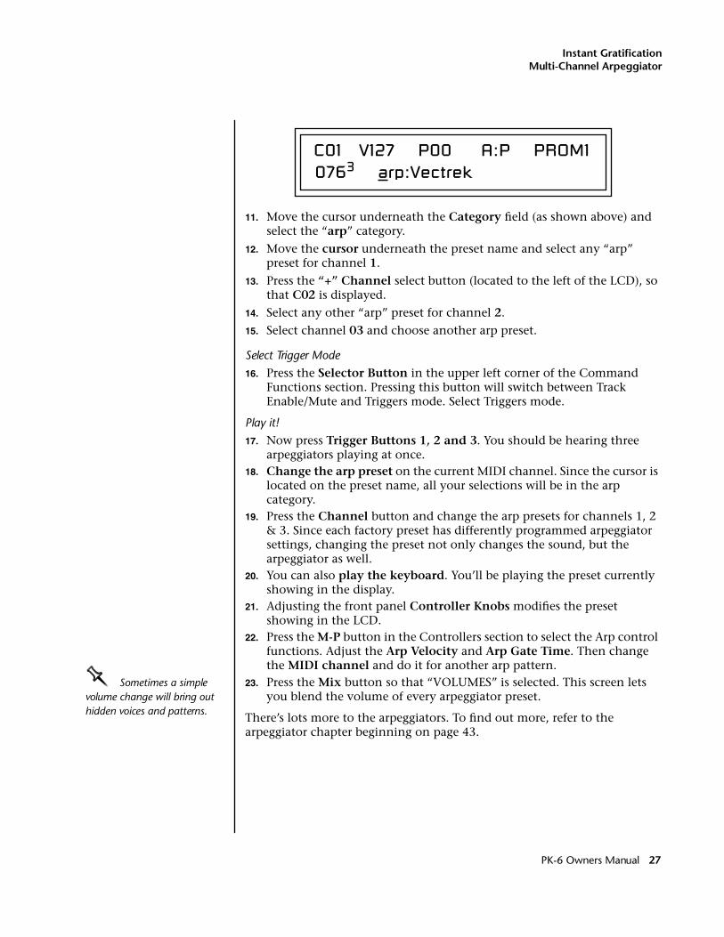
Instant GratificationMulti-Channel Arpeggiator
11. Move the cursor underneath the Category field (as shown above) and select the “arp” category.
12. Move the cursor underneath the preset name and select any “arp” preset for channel 1.
13. Press the “+” Channel select button (located to the left of the LCD), so that C02 is displayed.
14. Select any other “arp” preset for channel 2.
15. Select channel 03 and choose another arp preset.
Select Trigger Mode
16. Press the Selector Button in the upper left corner of the Command Functions section. Pressing this button will switch between Track Enable/Mute and Triggers mode. Select Triggers mode.
Play it!
17. Now press Trigger Buttons 1, 2 and 3. You should be hearing three arpeggiators playing at once.
18. Change the arp preset on the current MIDI channel. Since the cursor is located on the preset name, all your selections will be in the arp category.
19. Press the Channel button and change the arp presets for channels 1, 2 & 3. Since each factory preset has differently programmed arpeggiator settings, changing the preset not only changes the sound, but the arpeggiator as well.
20. You can also play the keyboard. You’ll be playing the preset currently showing in the display.
21. Adjusting the front panel Controller Knobs modifies the preset showing in the LCD.
22. Press the M-P button in the Controllers section to select the Arp control functions. Adjust the Arp Velocity and Arp Gate Time. Then change the MIDI channel and do it for another arp pattern.
OOOO Sometimes a simple volume change will bring out hidden voices and patterns.
23. Press the Mix button so that “VOLUMES” is selected. This screen lets you blend the volume of every arpeggiator preset.
There’s lots more to the arpeggiators. To find out more, refer to the arpeggiator chapter beginning on page 43.
C01 V127 P00 A:P PROM10763 arp:Vectrek
PK-6 Owners Manual 27
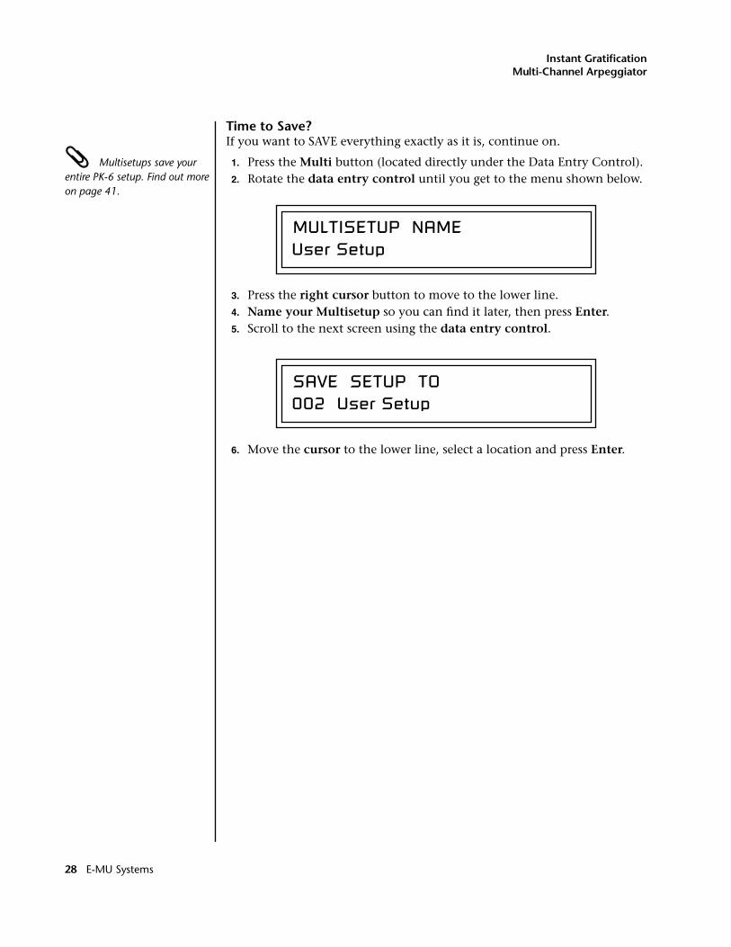
Instant GratificationMulti-Channel Arpeggiator
Time to Save?If you want to SAVE everything exactly as it is, continue on.
Multisetups save your entire PK-6 setup. Find out more on page 41.
1. Press the Multi button (located directly under the Data Entry Control).2. Rotate the data entry control until you get to the menu shown below.
3. Press the right cursor button to move to the lower line.4. Name your Multisetup so you can find it later, then press Enter.5. Scroll to the next screen using the data entry control.
6. Move the cursor to the lower line, select a location and press Enter.
MULTISETUP NAMEUser Setup
SAVE SETUP TO002 User Setup
28 E-MU Systems
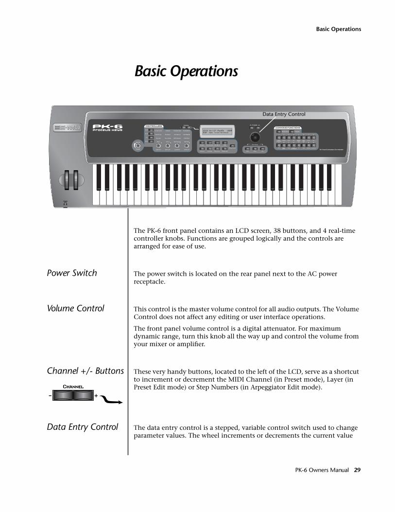
Basic Operations
Basic Operations
The PK-6 front panel contains an LCD screen, 38 buttons, and 4 real-time controller knobs. Functions are grouped logically and the controls are arranged for ease of use.
Power Switch The power switch is located on the rear panel next to the AC powerreceptacle.
Volume Control This control is the master volume control for all audio outputs. The Volume Control does not affect any editing or user interface operations.
The front panel volume control is a digital attenuator. For maximum dynamic range, turn this knob all the way up and control the volume from your mixer or amplifier.
Channel +/- Buttons These very handy buttons, located to the left of the LCD, serve as a shortcut to increment or decrement the MIDI Channel (in Preset mode), Layer (in Preset Edit mode) or Step Numbers (in Arpeggiator Edit mode).
Data Entry Control The data entry control is a stepped, variable control switch used to change parameter values. The wheel increments or decrements the current value
CO 1A Vo l 1 27 Pan00R SU ER0322 bas : I n t e r f e r ence
Data Entry Control
PK-6 Owners Manual 29
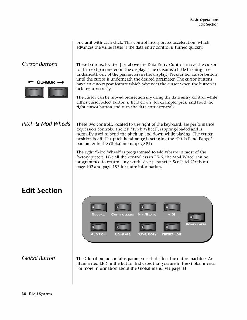
Basic OperationsEdit Section
one unit with each click. This control incorporates acceleration, which advances the value faster if the data entry control is turned quickly.
Cursor Buttons These buttons, located just above the Data Entry Control, move the cursor to the next parameter on the display. (The cursor is a little flashing line underneath one of the parameters in the display.) Press either cursor button until the cursor is underneath the desired parameter. The cursor buttons have an auto-repeat feature which advances the cursor when the button is held continuously.
The cursor can be moved bidirectionally using the data entry control while either cursor select button is held down (for example, press and hold the right cursor button and turn the data entry control).
Pitch & Mod Wheels These two controls, located to the right of the keyboard, are performance expression controls. The left “Pitch Wheel”, is spring-loaded and is normally used to bend the pitch up and down while playing. The center position is off. The pitch bend range is set using the “Pitch Bend Range” parameter in the Global menu (page 84).
The right “Mod Wheel” is programmed to add vibrato in most of the factory presets. Like all the controllers in PK-6, the Mod Wheel can be programmed to control any synthesizer parameter. See PatchCords on page 102 and page 157 for more information.
Edit Section
Global Button The Global menu contains parameters that affect the entire machine. An illuminated LED in the button indicates that you are in the Global menu. For more information about the Global menu, see page 83
30 E-MU Systems
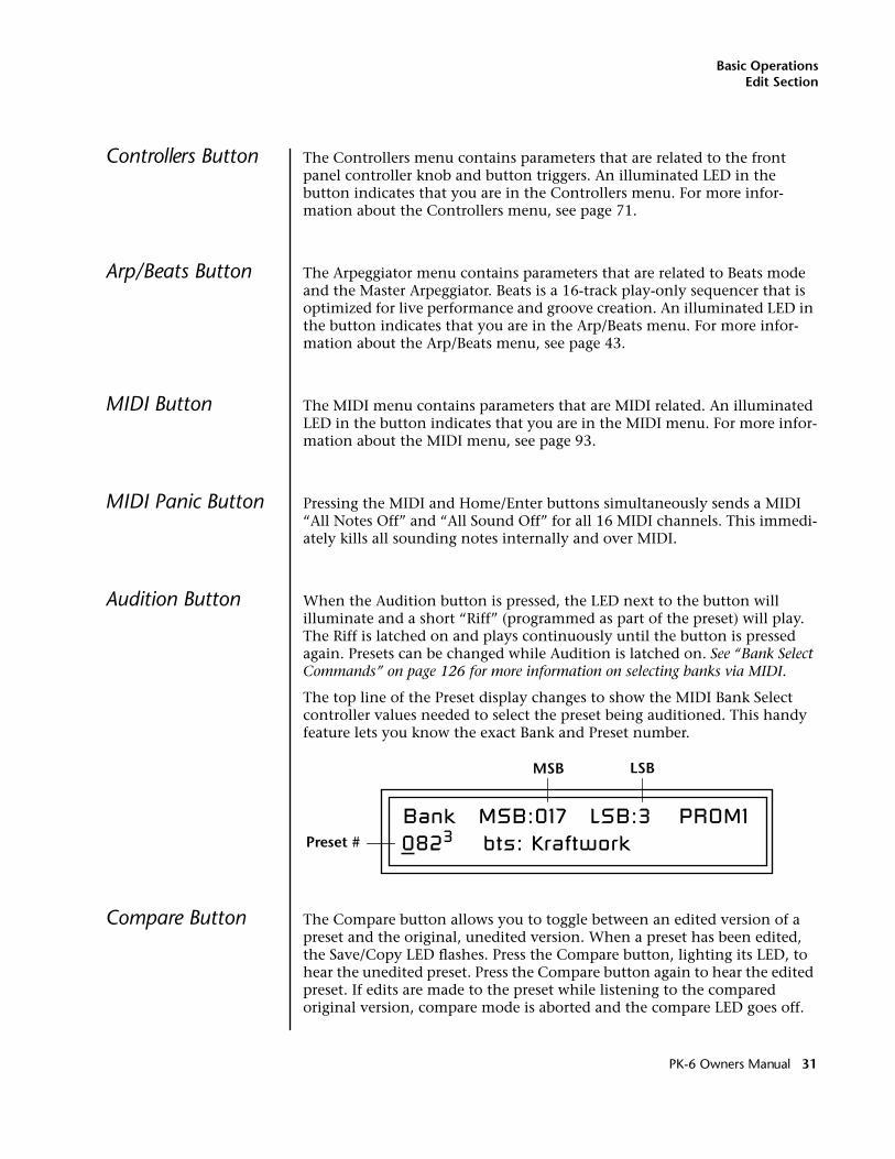
Basic OperationsEdit Section
Controllers Button The Controllers menu contains parameters that are related to the front panel controller knob and button triggers. An illuminated LED in the button indicates that you are in the Controllers menu. For more infor-mation about the Controllers menu, see page 71.
Arp/Beats Button The Arpeggiator menu contains parameters that are related to Beats mode and the Master Arpeggiator. Beats is a 16-track play-only sequencer that is optimized for live performance and groove creation. An illuminated LED in the button indicates that you are in the Arp/Beats menu. For more infor-mation about the Arp/Beats menu, see page 43.
MIDI Button The MIDI menu contains parameters that are MIDI related. An illuminated LED in the button indicates that you are in the MIDI menu. For more infor-mation about the MIDI menu, see page 93.
MIDI Panic Button Pressing the MIDI and Home/Enter buttons simultaneously sends a MIDI “All Notes Off” and “All Sound Off” for all 16 MIDI channels. This immedi-ately kills all sounding notes internally and over MIDI.
Audition Button When the Audition button is pressed, the LED next to the button will illuminate and a short “Riff” (programmed as part of the preset) will play. The Riff is latched on and plays continuously until the button is pressed again. Presets can be changed while Audition is latched on. See “Bank Select Commands” on page 126 for more information on selecting banks via MIDI.
The top line of the Preset display changes to show the MIDI Bank Select controller values needed to select the preset being auditioned. This handy feature lets you know the exact Bank and Preset number.
Compare Button The Compare button allows you to toggle between an edited version of a preset and the original, unedited version. When a preset has been edited, the Save/Copy LED flashes. Press the Compare button, lighting its LED, to hear the unedited preset. Press the Compare button again to hear the edited preset. If edits are made to the preset while listening to the compared original version, compare mode is aborted and the compare LED goes off.
Bank MSB:017 LSB:3 PROM10823 bts: Kraftwork
MSB LSB
Preset #
PK-6 Owners Manual 31
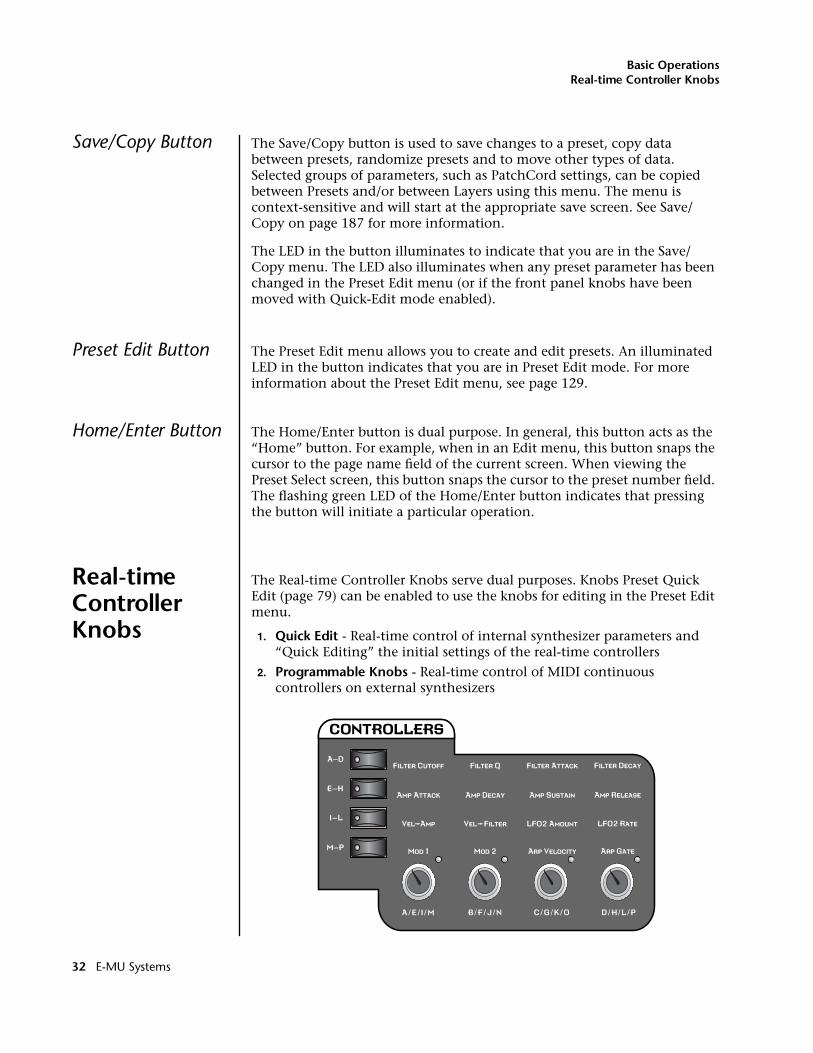
Basic OperationsReal-time Controller Knobs
Save/Copy Button The Save/Copy button is used to save changes to a preset, copy data between presets, randomize presets and to move other types of data. Selected groups of parameters, such as PatchCord settings, can be copied between Presets and/or between Layers using this menu. The menu is context-sensitive and will start at the appropriate save screen. See Save/Copy on page 187 for more information.
The LED in the button illuminates to indicate that you are in the Save/Copy menu. The LED also illuminates when any preset parameter has been changed in the Preset Edit menu (or if the front panel knobs have been moved with Quick-Edit mode enabled).
Preset Edit Button The Preset Edit menu allows you to create and edit presets. An illuminated LED in the button indicates that you are in Preset Edit mode. For more information about the Preset Edit menu, see page 129.
Home/Enter Button The Home/Enter button is dual purpose. In general, this button acts as the “Home” button. For example, when in an Edit menu, this button snaps the cursor to the page name field of the current screen. When viewing the Preset Select screen, this button snaps the cursor to the preset number field. The flashing green LED of the Home/Enter button indicates that pressing the button will initiate a particular operation.
Real-time Controller Knobs
The Real-time Controller Knobs serve dual purposes. Knobs Preset Quick Edit (page 79) can be enabled to use the knobs for editing in the Preset Edit menu.
1. Quick Edit - Real-time control of internal synthesizer parameters and “Quick Editing” the initial settings of the real-time controllers
2. Programmable Knobs - Real-time control of MIDI continuous controllers on external synthesizers
32 E-MU Systems
Basic OperationsReal-time Controller Knobs
Knob Functions Quick Edit modeThe Real-time controller knobs provide direct control of the PK-6’s synthe-sizer parameters when the Controller Function Select is set to Quick Edit.
There is an LED next to each of the control knobs which illuminates to indicate that the knob setting has been changed from the value programmed in the preset (“Knobs Preset Quick Edit” mode must be enabled in the Controllers menu). If the knob position is returned to the original setting, the LED is extinguished.
OOOO Quick Edit knob movements can be recorded into an external sequencer.
Initial controller values can be stored in every preset. When you move a knob with Quick-Edit enabled, the Initial Controller Value is updated with the knob’s new value. The knob’s LED lights indicating that the preset value has been changed. The MIDI A-P values are stored in the corresponding Initial Controller Amount parameter in the Preset Edit menu (see “Initial Controller Amount” on page 167). The Save/Copy button LED flashes to remind you that the preset has been edited. “Quick-Edits” made to a preset are lost if you select another preset before saving them.
The four rows of knobs always control the preset on the basic MIDI channel (the channel showing on the preset select screen), when the control switch is set to Quick Edit.
The labels (Filter Cutoff, Filter Q, Filter Attack, Filter Decay, etc.) printed on these rows show how the factory ROM presets are programmed to respond. (The controls may not exactly conform to the front panel labels depending on the preset.) You can change the way a preset responds to MIDI A-P messages from the Preset Edit menu (PatchCords). The knobs only generate a message when you move a knob to a new value. The current value jumps to the new value.
� To Quick-Edit a Preset:1. Select Quick Edit mode using the Controller Function Select button.
2. Use the Control Knobs to change the sound of the current preset as desired.
3. Press the Save/Copy button. You may have to turn the data entry control so that the display reads, “Save PRESET to.”
4. Press the right cursor button to select the bottom row.
5. Optional: Select a new preset location if you don’t want to overwrite the current preset, or if the current preset is a ROM preset.
6. Press the Enter button to save the preset.
PK-6 Owners Manual 33
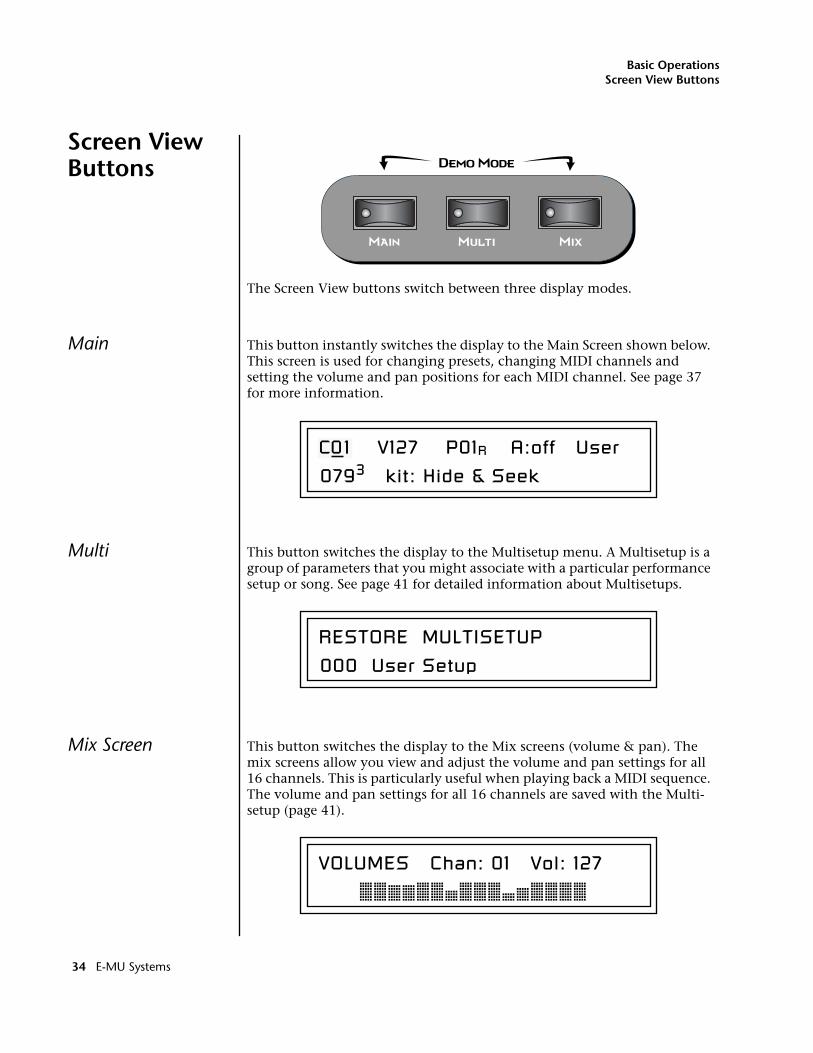
Basic OperationsScreen View Buttons
Screen View Buttons
The Screen View buttons switch between three display modes.
Main This button instantly switches the display to the Main Screen shown below. This screen is used for changing presets, changing MIDI channels and setting the volume and pan positions for each MIDI channel. See page 37 for more information.
Multi This button switches the display to the Multisetup menu. A Multisetup is a group of parameters that you might associate with a particular performance setup or song. See page 41 for detailed information about Multisetups.
Mix Screen This button switches the display to the Mix screens (volume & pan). The mix screens allow you view and adjust the volume and pan settings for all 16 channels. This is particularly useful when playing back a MIDI sequence. The volume and pan settings for all 16 channels are saved with the Multi-setup (page 41).
C01 V127 P01R A:off User
0793 kit: Hide & Seek
RESTORE MULTISETUP
000 User Setup
VOLUMES Chan: 01 Vol: 127
34 E-MU Systems
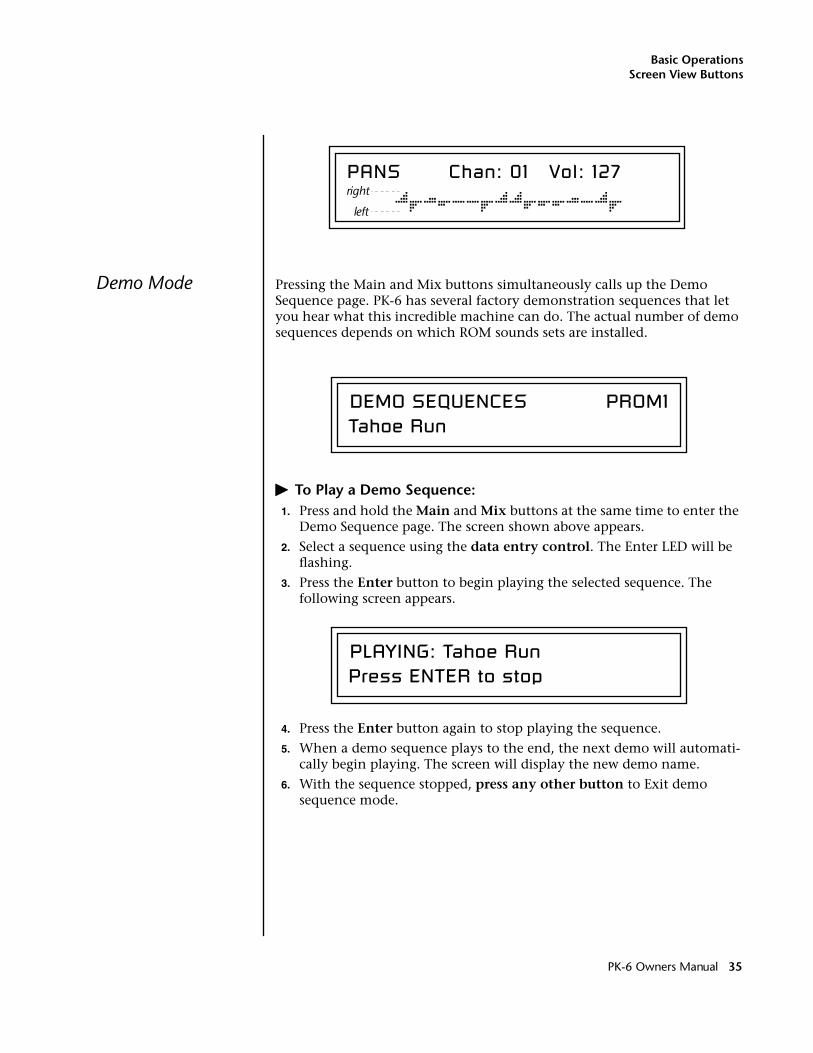
Basic OperationsScreen View Buttons
Demo Mode Pressing the Main and Mix buttons simultaneously calls up the Demo Sequence page. PK-6 has several factory demonstration sequences that let you hear what this incredible machine can do. The actual number of demo sequences depends on which ROM sounds sets are installed.
� To Play a Demo Sequence:1. Press and hold the Main and Mix buttons at the same time to enter the
Demo Sequence page. The screen shown above appears.
2. Select a sequence using the data entry control. The Enter LED will be flashing.
3. Press the Enter button to begin playing the selected sequence. The following screen appears.
4. Press the Enter button again to stop playing the sequence.
5. When a demo sequence plays to the end, the next demo will automati-cally begin playing. The screen will display the new demo name.
6. With the sequence stopped, press any other button to Exit demo sequence mode.
PANS Chan: 01 Vol: 127 right
left
DEMO SEQUENCES PROM1Tahoe Run
PLAYING: Tahoe RunPress ENTER to stop
PK-6 Owners Manual 35
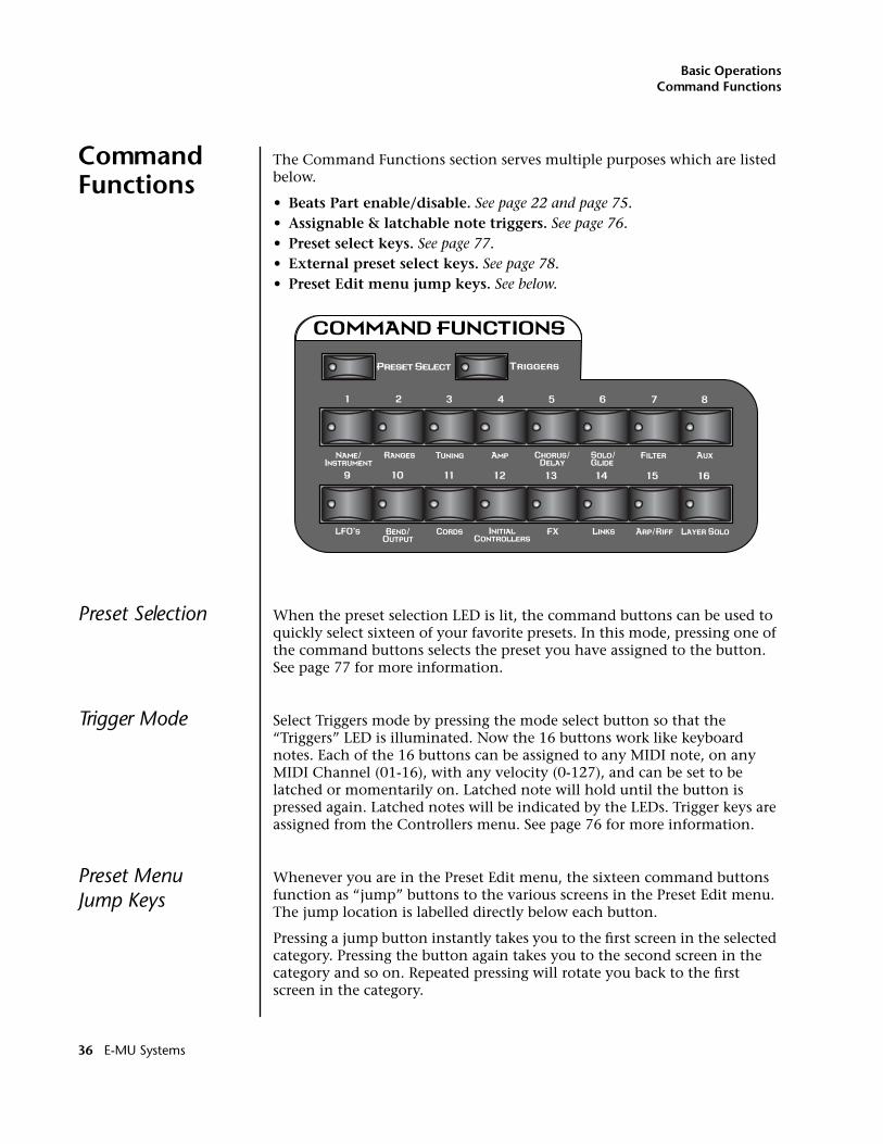
Basic OperationsCommand Functions
Command Functions
The Command Functions section serves multiple purposes which are listed below.
• Beats Part enable/disable. See page 22 and page 75.• Assignable & latchable note triggers. See page 76.• Preset select keys. See page 77.• External preset select keys. See page 78.• Preset Edit menu jump keys. See below.
Preset Selection When the preset selection LED is lit, the command buttons can be used to quickly select sixteen of your favorite presets. In this mode, pressing one of the command buttons selects the preset you have assigned to the button. See page 77 for more information.
Trigger Mode Select Triggers mode by pressing the mode select button so that the “Triggers” LED is illuminated. Now the 16 buttons work like keyboard notes. Each of the 16 buttons can be assigned to any MIDI note, on any MIDI Channel (01-16), with any velocity (0-127), and can be set to be latched or momentarily on. Latched note will hold until the button is pressed again. Latched notes will be indicated by the LEDs. Trigger keys are assigned from the Controllers menu. See page 76 for more information.
Preset MenuJump Keys
Whenever you are in the Preset Edit menu, the sixteen command buttons function as “jump” buttons to the various screens in the Preset Edit menu. The jump location is labelled directly below each button.
Pressing a jump button instantly takes you to the first screen in the selected category. Pressing the button again takes you to the second screen in the category and so on. Repeated pressing will rotate you back to the first screen in the category.
36 E-MU Systems
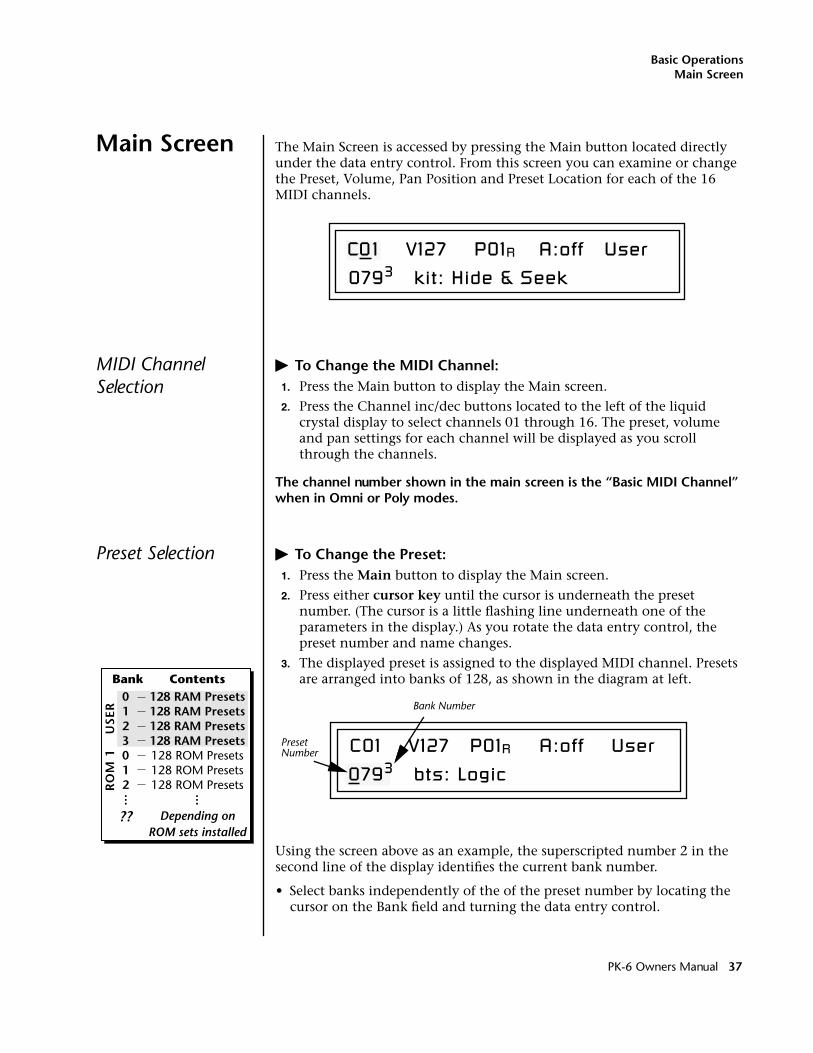
Basic OperationsMain Screen
Main Screen The Main Screen is accessed by pressing the Main button located directly under the data entry control. From this screen you can examine or change the Preset, Volume, Pan Position and Preset Location for each of the 16 MIDI channels.
MIDI Channel Selection
� To Change the MIDI Channel:1. Press the Main button to display the Main screen.
2. Press the Channel inc/dec buttons located to the left of the liquid crystal display to select channels 01 through 16. The preset, volume and pan settings for each channel will be displayed as you scroll through the channels.
The channel number shown in the main screen is the “Basic MIDI Channel” when in Omni or Poly modes.
Preset Selection � To Change the Preset:1. Press the Main button to display the Main screen.
2. Press either cursor key until the cursor is underneath the preset number. (The cursor is a little flashing line underneath one of the parameters in the display.) As you rotate the data entry control, the preset number and name changes.
3. The displayed preset is assigned to the displayed MIDI channel. Presets are arranged into banks of 128, as shown in the diagram at left.
Using the screen above as an example, the superscripted number 2 in the second line of the display identifies the current bank number.
• Select banks independently of the of the preset number by locating the cursor on the Bank field and turning the data entry control.
C01 V127 P01R A:off User
0793 kit: Hide & Seek
Bank Contents128 RAM Presets128 RAM Presets128 RAM Presets128 RAM Presets128 ROM Presets128 ROM Presets128 ROM Presets
Depending onROM sets installed
0123012
??
USE
RR
OM
1
C01 V127 P01R A:off UserNumberPreset
Bank Number
0793 bts: Logic
PK-6 Owners Manual 37
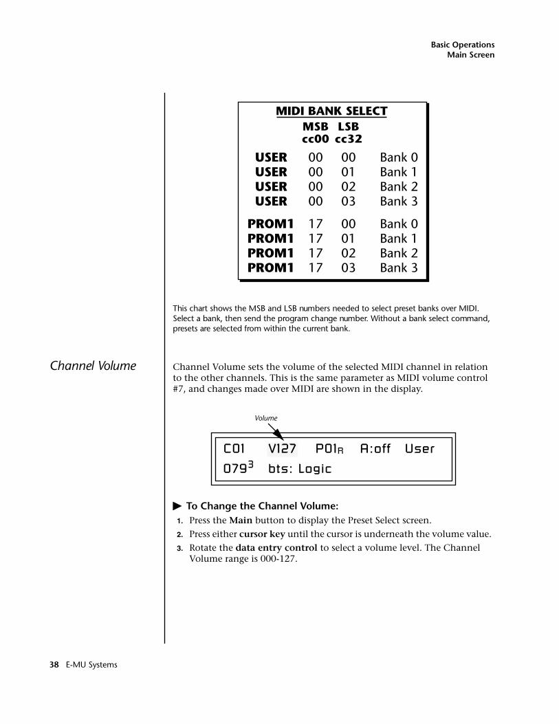
Basic OperationsMain Screen
This chart shows the MSB and LSB numbers needed to select preset banks over MIDI. Select a bank, then send the program change number. Without a bank select command, presets are selected from within the current bank.
Channel Volume Channel Volume sets the volume of the selected MIDI channel in relation to the other channels. This is the same parameter as MIDI volume control #7, and changes made over MIDI are shown in the display.
� To Change the Channel Volume:1. Press the Main button to display the Preset Select screen.
2. Press either cursor key until the cursor is underneath the volume value.
3. Rotate the data entry control to select a volume level. The Channel Volume range is 000-127.
PROM1PROM1PROM1PROM1
Bank 0Bank 1Bank 2Bank 3
Bank 0Bank 1Bank 2Bank 3
00000000
17171717
00010203
00010203
USERUSERUSERUSER
MIDI BANK SELECT
cc00 cc32MSB LSB
0793 bts: Logic
Volume
C01 V127 P01R A:off User
38 E-MU Systems
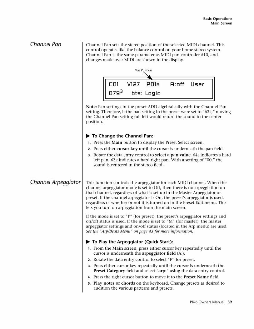
Basic OperationsMain Screen
Channel Pan Channel Pan sets the stereo position of the selected MIDI channel. This control operates like the balance control on your home stereo system. Channel Pan is the same parameter as MIDI pan controller #10, and changes made over MIDI are shown in the display.
Note: Pan settings in the preset ADD algebraically with the Channel Pan setting. Therefore, if the pan setting in the preset were set to “63R,” moving the Channel Pan setting full left would return the sound to the center position.
� To Change the Channel Pan:1. Press the Main button to display the Preset Select screen.
2. Press either cursor key until the cursor is underneath the pan field.
3. Rotate the data entry control to select a pan value. 64L indicates a hard left pan, 63R indicates a hard right pan. With a setting of “00,” the sound is centered in the stereo field.
Channel Arpeggiator This function controls the arpeggiator for each MIDI channel. When the channel arpeggiator mode is set to Off, then there is no arpeggiation on that channel, regardless of what is set up in the Master Arpeggiator or preset. If the channel arpeggiator is On, the preset’s arpeggiator is used, regardless of whether or not it is turned on in the Preset Edit menu. This lets you turn on arpeggiation from the main screen.
If the mode is set to “P” (for preset), the preset’s arpeggiator settings and on/off status is used. If the mode is set to “M” (for master), the master arpeggiator settings and on/off status (located in the Arp menu) are used. See the “Arp/Beats Menu” on page 43 for more information.
� To Play the Arpeggiator (Quick Start):1. From the Main screen, press either cursor key repeatedly until the
cursor is underneath the arpeggiator field (A:).
2. Rotate the data entry control to select “P” for preset.
3. Press either cursor key repeatedly until the cursor is underneath the Preset Category field and select “arp:” using the data entry control.
4. Press the right cursor button to move it to the Preset Name field.
5. Play notes or chords on the keyboard. Change presets as desired to audition the various patterns and presets.
0793 bts: Logic
C01 V127 P01R A:off User
Pan Position
PK-6 Owners Manual 39
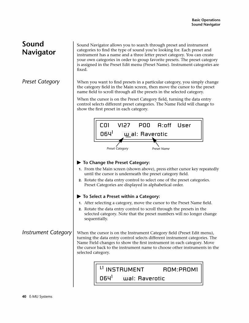
Basic OperationsSound Navigator
Sound Navigator
Sound Navigator allows you to search through preset and instrument categories to find the type of sound you’re looking for. Each preset and instrument has a name and a three letter preset category. You can create your own categories in order to group favorite presets. The preset category is assigned in the Preset Edit menu (Preset Name). Instrument categories are fixed.
Preset Category When you want to find presets in a particular category, you simply change the category field in the Main screen, then move the cursor to the preset name field to scroll through all the presets in the selected category.
When the cursor is on the Preset Category field, turning the data entry control selects different preset categories. The Name Field will change to show the first preset in each category.
� To Change the Preset Category:1. From the Main screen (shown above), press either cursor key repeatedly
until the cursor is underneath the preset category field.
2. Rotate the data entry control to select one of the preset categories. Preset Categories are displayed in alphabetical order.
� To Select a Preset within a Category:1. After selecting a category, move the cursor to the Preset Name field.
2. Rotate the data entry control to scroll through the presets in the selected category. Note that the preset numbers will no longer change sequentially.
Instrument Category When the cursor is on the Instrument Category field (Preset Edit menu), turning the data entry control selects different instrument categories. The Name Field changes to show the first instrument in each category. Move the cursor back to the instrument name to choose other instruments in the selected category.
C01 V127 P00 A:off User
0641 w al: Raverotic
Preset Category Preset Name
L1 INSTRUMENT ROM:PROM1
0641 wal: Raverotic
40 E-MU Systems
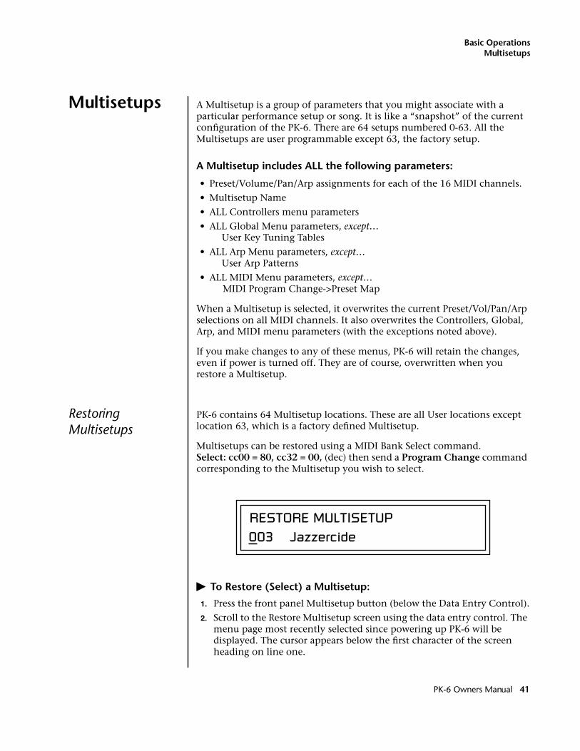
Basic OperationsMultisetups
Multisetups A Multisetup is a group of parameters that you might associate with a particular performance setup or song. It is like a “snapshot” of the current configuration of the PK-6. There are 64 setups numbered 0-63. All the Multisetups are user programmable except 63, the factory setup.
A Multisetup includes ALL the following parameters:
• Preset/Volume/Pan/Arp assignments for each of the 16 MIDI channels.
• Multisetup Name
• ALL Controllers menu parameters
• ALL Global Menu parameters, except…User Key Tuning Tables
• ALL Arp Menu parameters, except…User Arp Patterns
• ALL MIDI Menu parameters, except…MIDI Program Change->Preset Map
When a Multisetup is selected, it overwrites the current Preset/Vol/Pan/Arp selections on all MIDI channels. It also overwrites the Controllers, Global, Arp, and MIDI menu parameters (with the exceptions noted above).
If you make changes to any of these menus, PK-6 will retain the changes, even if power is turned off. They are of course, overwritten when you restore a Multisetup.
Restoring Multisetups
PK-6 contains 64 Multisetup locations. These are all User locations except location 63, which is a factory defined Multisetup.
Multisetups can be restored using a MIDI Bank Select command. Select: cc00 = 80, cc32 = 00, (dec) then send a Program Change command corresponding to the Multisetup you wish to select.
� To Restore (Select) a Multisetup:
1. Press the front panel Multisetup button (below the Data Entry Control).
2. Scroll to the Restore Multisetup screen using the data entry control. The menu page most recently selected since powering up PK-6 will be displayed. The cursor appears below the first character of the screen heading on line one.
RESTORE MULTISETUP003 Jazzercide
PK-6 Owners Manual 41
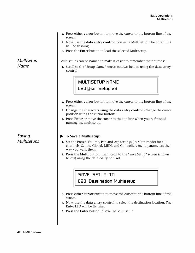
Basic OperationsMultisetups
3. Press either cursor button to move the cursor to the bottom line of the screen.
4. Now, use the data entry control to select a Multisetup. The Enter LED will be flashing.
5. Press the Enter button to load the selected Multisetup.
MultisetupName
Multisetups can be named to make it easier to remember their purpose.
1. Scroll to the “Setup Name” screen (shown below) using the data entry control.
2. Press either cursor button to move the cursor to the bottom line of the screen.
3. Change the characters using the data entry control. Change the cursor position using the cursor buttons.
4. Press Enter or move the cursor to the top line when you’re finished naming the multisetup.
SavingMultisetups
� To Save a Multisetup:
1. Set the Preset, Volume, Pan and Arp settings (in Main mode) for all channels. Set the Global, MIDI, and Controllers menu parameters the way you want them.
2. Press the Multi button, then scroll to the “Save Setup” screen (shown below) using the data entry control.
3. Press either cursor button to move the cursor to the bottom line of the screen.
4. Now, use the data entry control to select the destination location. The Enter LED will be flashing.
5. Press the Enter button to save the Multisetup.
MULTISETUP NAME020 User Setup 23
SAVE SETUP TO020 Destination Multisetup
42 E-MU Systems
Arp/Beats Menu
Arp/Beats Menu
PK-6’s Beats mode allows you to trigger, latch and unlatch synced loops and grooves from separate keys on your keyboard. Simply select a bts: preset and play the 16 trigger keys to bring specific Parts in and out. This is Macro-Music!
PK-6 can also run up to 16 simultaneously synced arpeggiators, each with a different preset sound. The arpeggiators can either play one of 7 chord arpeggios or can be set to play a pattern, which is a stored sequence of notes. Combined with Beats, the sheer number of musical permutations is staggering!
� To enable the Arpeggiator/Beats menu:
Press the Arp button, lighting the LED. The Arp screen displays the menu page most recently selected since powering up PK-6. The cursor appears below the first character of the screen heading on line one.
Arp parameters are automatically saved to the current multisetup when you exit the menu, but you may wish to save to another location.
If another Multisetup is “Restored” any unsaved changes will be lost if you haven’t saved the Multisetup.
� To select a new screen:
Press the Home/Enter button or press the Cursor button repeatedly until the cursor is below the screen title heading on the top line of the display. Rotate the data entry control to select another screen.
� To modify a parameter:
Press either Cursor button repeatedly (or hold down the right cursor button while turning the data entry control) until the cursor is below the desired parameter value. Rotate the data entry control to change the value.
� To access a submenu:
The Master Arpeggiator screens have submenus which are accessed by pressing the cursor buttons to move the cursor to the lower left corner of the display. Select the submenu function using the data entry control.
� To save Arpeggiator parameters:
Press the front panel Multi button and scroll to “Save Setup To”. Select a Setup number and press Enter. See “Saving Multisetups” on page 42.
� To return to the previously selected Mode/View screen:
Press the Arp/Beats button, turning off the LED.
PK-6 Owners Manual 43
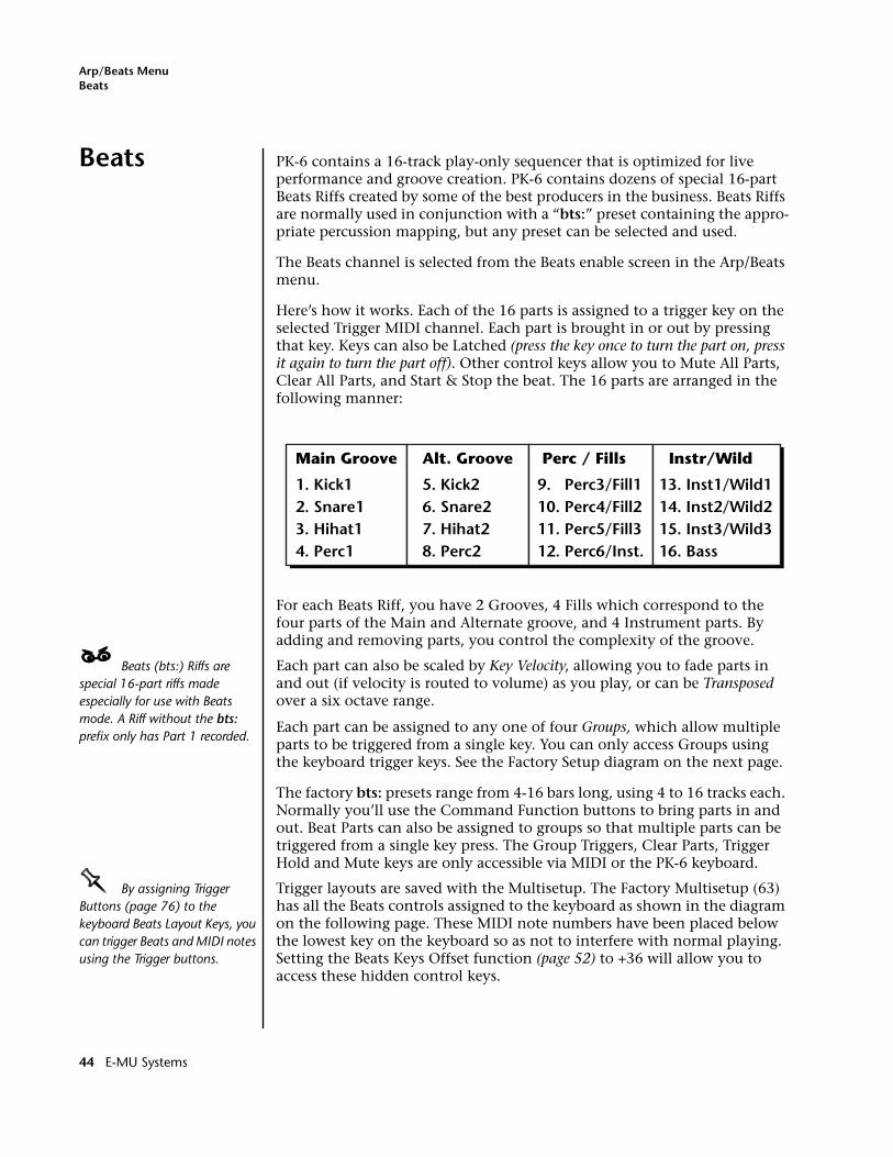
Arp/Beats MenuBeats
Beats PK-6 contains a 16-track play-only sequencer that is optimized for live performance and groove creation. PK-6 contains dozens of special 16-part Beats Riffs created by some of the best producers in the business. Beats Riffs are normally used in conjunction with a “bts:” preset containing the appro-priate percussion mapping, but any preset can be selected and used.
The Beats channel is selected from the Beats enable screen in the Arp/Beats menu.
Here’s how it works. Each of the 16 parts is assigned to a trigger key on the selected Trigger MIDI channel. Each part is brought in or out by pressing that key. Keys can also be Latched (press the key once to turn the part on, press it again to turn the part off). Other control keys allow you to Mute All Parts, Clear All Parts, and Start & Stop the beat. The 16 parts are arranged in the following manner:
For each Beats Riff, you have 2 Grooves, 4 Fills which correspond to the four parts of the Main and Alternate groove, and 4 Instrument parts. By adding and removing parts, you control the complexity of the groove.
____ Beats (bts:) Riffs are special 16-part riffs made especially for use with Beats mode. A Riff without the bts: prefix only has Part 1 recorded.
Each part can also be scaled by Key Velocity, allowing you to fade parts in and out (if velocity is routed to volume) as you play, or can be Transposed over a six octave range.
Each part can be assigned to any one of four Groups, which allow multiple parts to be triggered from a single key. You can only access Groups using the keyboard trigger keys. See the Factory Setup diagram on the next page.
The factory bts: presets range from 4-16 bars long, using 4 to 16 tracks each. Normally you’ll use the Command Function buttons to bring parts in and out. Beat Parts can also be assigned to groups so that multiple parts can be triggered from a single key press. The Group Triggers, Clear Parts, Trigger Hold and Mute keys are only accessible via MIDI or the PK-6 keyboard.
OOOO By assigning Trigger Buttons (page 76) to the keyboard Beats Layout Keys, you can trigger Beats and MIDI notes using the Trigger buttons.
Trigger layouts are saved with the Multisetup. The Factory Multisetup (63) has all the Beats controls assigned to the keyboard as shown in the diagram on the following page. These MIDI note numbers have been placed below the lowest key on the keyboard so as not to interfere with normal playing. Setting the Beats Keys Offset function (page 52) to +36 will allow you to access these hidden control keys.
Alt. Groove
5. Kick2 6. Snare2 7. Hihat2 8. Perc2
Perc / Fills
9. Perc3/Fill1 10. Perc4/Fill2 11. Perc5/Fill3 12. Perc6/Inst.
Instr/Wild
13. Inst1/Wild1 14. Inst2/Wild2 15. Inst3/Wild3 16. Bass
Main Groove
1. Kick1 2. Snare1 3. Hihat1 4. Perc1
44 E-MU Systems
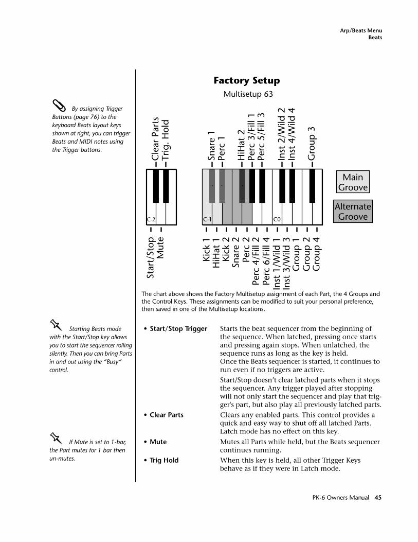
Arp/Beats MenuBeats
The chart above shows the Factory Multisetup assignment of each Part, the 4 Groups and the Control Keys. These assignments can be modified to suit your personal preference, then saved in one of the Multisetup locations.
OOOO Starting Beats mode with the Start/Stop key allows you to start the sequencer rolling silently. Then you can bring Parts in and out using the “Busy” control.
• Start/Stop Trigger Starts the beat sequencer from the beginning of the sequence. When latched, pressing once starts and pressing again stops. When unlatched, the sequence runs as long as the key is held.Once the Beats sequencer is started, it continues to run even if no triggers are active.
Start/Stop doesn’t clear latched parts when it stops the sequencer. Any trigger played after stopping will not only start the sequencer and play that trig-ger's part, but also play all previously latched parts.
• Clear Parts Clears any enabled parts. This control provides a quick and easy way to shut off all latched Parts. Latch mode has no effect on this key.
OOOO If Mute is set to 1-bar, the Part mutes for 1 bar then un-mutes.
• Mute Mutes all Parts while held, but the Beats sequencer continues running.
• Trig Hold When this key is held, all other Trigger Keys behave as if they were in Latch mode.
Multisetup 63
Factory Setup
MainGroove
AlternateGroove
HiH
at 1
Kick
2
Kick
1
Snar
e 2
Perc
2Pe
rc 4
/Fill
2Pe
rc 6
/Fill
4In
st 1
/Wild
1In
st 3
/Wild
3G
roup
1 G
roup
2G
roup
4
Perc
1Sn
are
1
HiH
at 2
Perc
3/F
ill 1
Perc
5/F
ill 3
Inst
2/W
ild 2
Inst
4/W
ild 4
Gro
up 3
C-1 C0
Star
t/St
opM
ute
Cle
ar P
arts
Trig
. Hol
d
C-2
By assigning Trigger Buttons (page 76) to the keyboard Beats layout keys shown at right, you can trigger Beats and MIDI notes using the Trigger buttons.
PK-6 Owners Manual 45
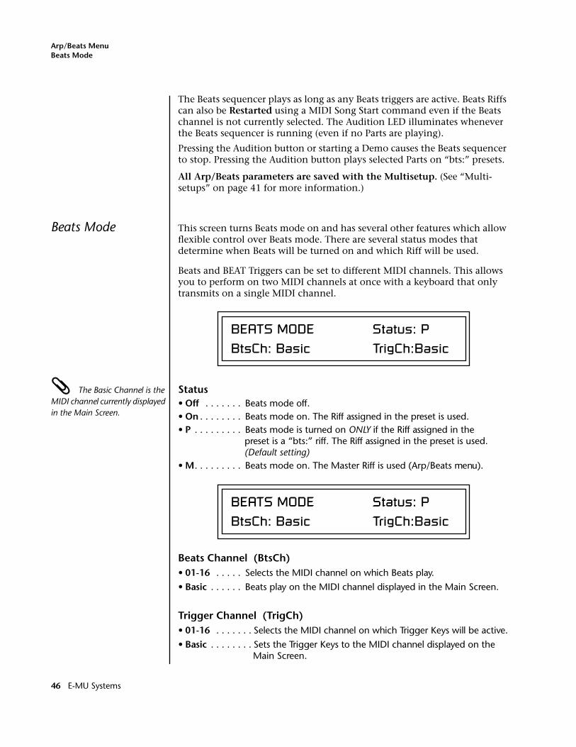
Arp/Beats MenuBeats Mode
The Beats sequencer plays as long as any Beats triggers are active. Beats Riffs can also be Restarted using a MIDI Song Start command even if the Beats channel is not currently selected. The Audition LED illuminates whenever the Beats sequencer is running (even if no Parts are playing).
Pressing the Audition button or starting a Demo causes the Beats sequencer to stop. Pressing the Audition button plays selected Parts on “bts:” presets.
All Arp/Beats parameters are saved with the Multisetup. (See “Multi-setups” on page 41 for more information.)
Beats Mode This screen turns Beats mode on and has several other features which allow flexible control over Beats mode. There are several status modes that determine when Beats will be turned on and which Riff will be used.
Beats and BEAT Triggers can be set to different MIDI channels. This allows you to perform on two MIDI channels at once with a keyboard that only transmits on a single MIDI channel.
The Basic Channel is the MIDI channel currently displayed in the Main Screen.
Status• Off . . . . . . . Beats mode off.• On . . . . . . . . Beats mode on. The Riff assigned in the preset is used. • P . . . . . . . . . Beats mode is turned on ONLY if the Riff assigned in the
preset is a “bts:” riff. The Riff assigned in the preset is used. (Default setting)
• M. . . . . . . . . Beats mode on. The Master Riff is used (Arp/Beats menu).
Beats Channel (BtsCh)• 01-16 . . . . . Selects the MIDI channel on which Beats play.
• Basic . . . . . . Beats play on the MIDI channel displayed in the Main Screen.
Trigger Channel (TrigCh)• 01-16 . . . . . . . Selects the MIDI channel on which Trigger Keys will be active.
• Basic . . . . . . . . Sets the Trigger Keys to the MIDI channel displayed on the Main Screen.
BEATS MODE Status: PBtsCh: Basic TrigCh:Basic
BEATS MODE Status: PBtsCh: Basic TrigCh:Basic
46 E-MU Systems
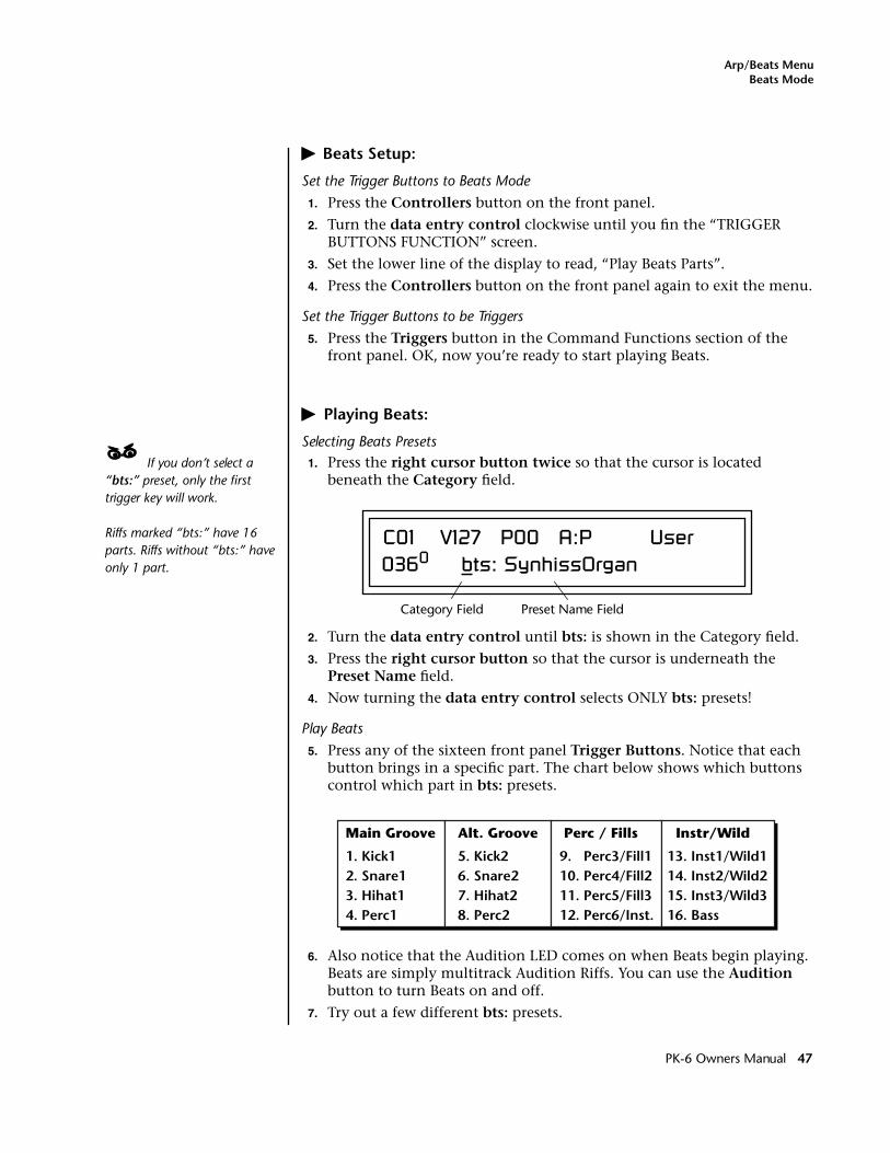
Arp/Beats MenuBeats Mode
� Beats Setup:
Set the Trigger Buttons to Beats Mode
1. Press the Controllers button on the front panel.
2. Turn the data entry control clockwise until you fin the “TRIGGER BUTTONS FUNCTION” screen.
3. Set the lower line of the display to read, “Play Beats Parts”.
4. Press the Controllers button on the front panel again to exit the menu.
Set the Trigger Buttons to be Triggers
5. Press the Triggers button in the Command Functions section of the front panel. OK, now you’re ready to start playing Beats.
� Playing Beats:
Selecting Beats Presets____ If you don’t select a “bts:” preset, only the first trigger key will work.
Riffs marked “bts:” have 16 parts. Riffs without “bts:” have only 1 part.
1. Press the right cursor button twice so that the cursor is located beneath the Category field.
2. Turn the data entry control until bts: is shown in the Category field.
3. Press the right cursor button so that the cursor is underneath the Preset Name field.
4. Now turning the data entry control selects ONLY bts: presets!
Play Beats
5. Press any of the sixteen front panel Trigger Buttons. Notice that each button brings in a specific part. The chart below shows which buttons control which part in bts: presets.
6. Also notice that the Audition LED comes on when Beats begin playing. Beats are simply multitrack Audition Riffs. You can use the Audition button to turn Beats on and off.
7. Try out a few different bts: presets.
C01 V127 P00 A:P User0360 bts: SynhissOrgan
Category Field Preset Name Field
Alt. Groove
5. Kick2 6. Snare2 7. Hihat2 8. Perc2
Perc / Fills
9. Perc3/Fill1 10. Perc4/Fill2 11. Perc5/Fill3 12. Perc6/Inst.
Instr/Wild
13. Inst1/Wild1 14. Inst2/Wild2 15. Inst3/Wild3 16. Bass
Main Groove
1. Kick1 2. Snare1 3. Hihat1 4. Perc1
PK-6 Owners Manual 47
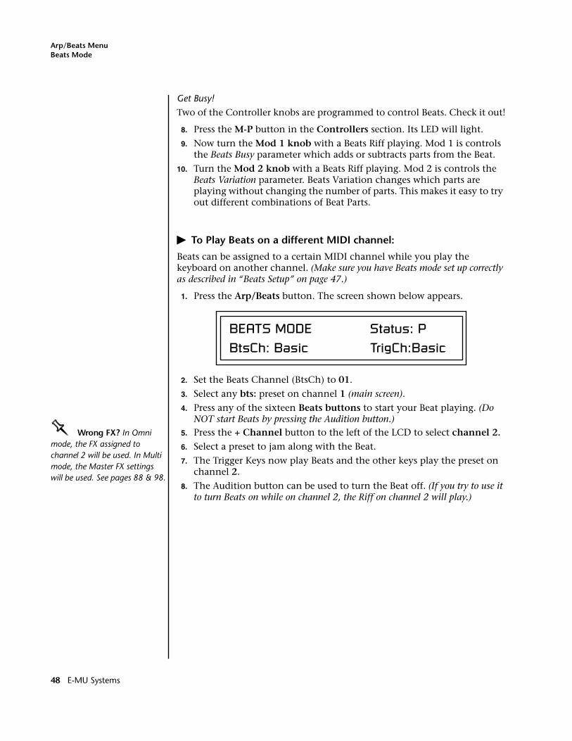
Arp/Beats MenuBeats Mode
Get Busy!
Two of the Controller knobs are programmed to control Beats. Check it out!
8. Press the M-P button in the Controllers section. Its LED will light.
9. Now turn the Mod 1 knob with a Beats Riff playing. Mod 1 is controls the Beats Busy parameter which adds or subtracts parts from the Beat.
10. Turn the Mod 2 knob with a Beats Riff playing. Mod 2 is controls the Beats Variation parameter. Beats Variation changes which parts are playing without changing the number of parts. This makes it easy to try out different combinations of Beat Parts.
� To Play Beats on a different MIDI channel:
Beats can be assigned to a certain MIDI channel while you play the keyboard on another channel. (Make sure you have Beats mode set up correctly as described in “Beats Setup” on page 47.)
1. Press the Arp/Beats button. The screen shown below appears.
2. Set the Beats Channel (BtsCh) to 01.
3. Select any bts: preset on channel 1 (main screen).
4. Press any of the sixteen Beats buttons to start your Beat playing. (Do NOT start Beats by pressing the Audition button.)
OOOO Wrong FX? In Omni mode, the FX assigned to channel 2 will be used. In Multi mode, the Master FX settings will be used. See pages 88 & 98.
5. Press the + Channel button to the left of the LCD to select channel 2.
6. Select a preset to jam along with the Beat.
7. The Trigger Keys now play Beats and the other keys play the preset on channel 2.
8. The Audition button can be used to turn the Beat off. (If you try to use it to turn Beats on while on channel 2, the Riff on channel 2 will play.)
BEATS MODE Status: PBtsCh: Basic TrigCh:Basic
48 E-MU Systems
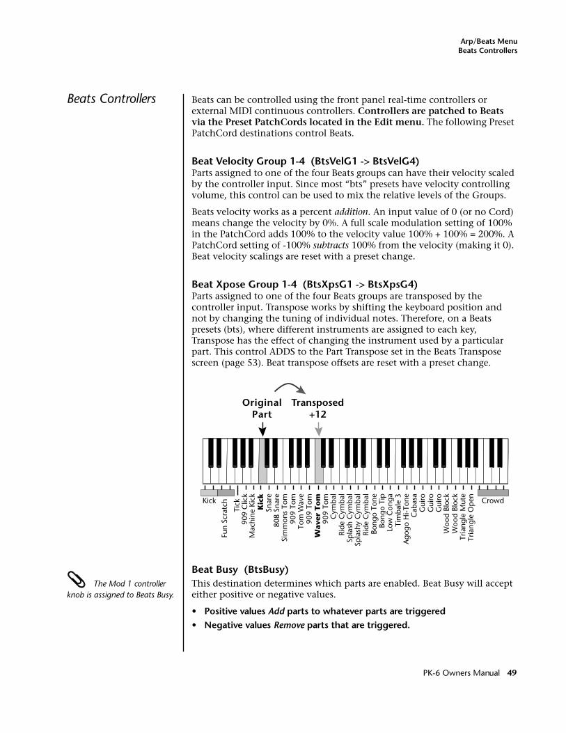
Arp/Beats MenuBeats Controllers
Beats Controllers Beats can be controlled using the front panel real-time controllers or external MIDI continuous controllers. Controllers are patched to Beats via the Preset PatchCords located in the Edit menu. The following Preset PatchCord destinations control Beats.
Beat Velocity Group 1-4 (BtsVelG1 -> BtsVelG4)Parts assigned to one of the four Beats groups can have their velocity scaled by the controller input. Since most “bts” presets have velocity controlling volume, this control can be used to mix the relative levels of the Groups.
Beats velocity works as a percent addition. An input value of 0 (or no Cord) means change the velocity by 0%. A full scale modulation setting of 100% in the PatchCord adds 100% to the velocity value 100% + 100% = 200%. A PatchCord setting of -100% subtracts 100% from the velocity (making it 0). Beat velocity scalings are reset with a preset change.
Beat Xpose Group 1-4 (BtsXpsG1 -> BtsXpsG4)Parts assigned to one of the four Beats groups are transposed by the controller input. Transpose works by shifting the keyboard position and not by changing the tuning of individual notes. Therefore, on a Beats presets (bts), where different instruments are assigned to each key, Transpose has the effect of changing the instrument used by a particular part. This control ADDS to the Part Transpose set in the Beats Transpose screen (page 53). Beat transpose offsets are reset with a preset change.
Beat Busy (BtsBusy) The Mod 1 controller knob is assigned to Beats Busy.
This destination determines which parts are enabled. Beat Busy will accept either positive or negative values.
• Positive values Add parts to whatever parts are triggered• Negative values Remove parts that are triggered.
Snar
e
Fun
Scra
tch
808
Snar
e
Mac
hine
Kic
kK
ick
Tick
909
Clic
k
Sim
mon
s To
m90
9 To
mTo
m W
ave
909
Tom
Wav
er T
om
909
Tom
Cym
bal
Ride
Cym
bal
Spla
sh C
ymba
lSp
lash
y C
ymba
lRi
de C
ymba
lBo
ngo
Tone
Bong
o Ti
pLo
w C
onga
Tim
bale
3A
gogo
Hi-T
one
Cab
asa
Gui
roG
uiro
Gui
roW
ood
Bloc
kW
ood
Bloc
kTr
iang
le M
ute
Tria
ngle
Ope
n
Kick Crowd
OriginalPart
Transposed+12
PK-6 Owners Manual 49
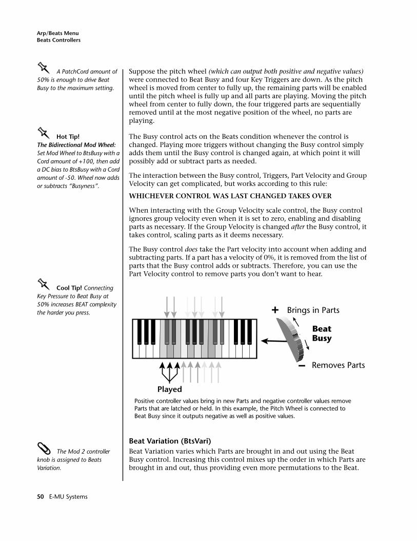
Arp/Beats MenuBeats Controllers
OOOO A PatchCord amount of 50% is enough to drive Beat Busy to the maximum setting.
Suppose the pitch wheel (which can output both positive and negative values) were connected to Beat Busy and four Key Triggers are down. As the pitch wheel is moved from center to fully up, the remaining parts will be enabled until the pitch wheel is fully up and all parts are playing. Moving the pitch wheel from center to fully down, the four triggered parts are sequentially removed until at the most negative position of the wheel, no parts are playing.
OOOO Hot Tip!The Bidirectional Mod Wheel: Set Mod Wheel to BtsBusy with a Cord amount of +100, then add a DC bias to BtsBusy with a Cord amount of -50. Wheel now adds or subtracts “Busyness”.
The Busy control acts on the Beats condition whenever the control is changed. Playing more triggers without changing the Busy control simply adds them until the Busy control is changed again, at which point it will possibly add or subtract parts as needed.
The interaction between the Busy control, Triggers, Part Velocity and Group Velocity can get complicated, but works according to this rule:
WHICHEVER CONTROL WAS LAST CHANGED TAKES OVER
When interacting with the Group Velocity scale control, the Busy control ignores group velocity even when it is set to zero, enabling and disabling parts as necessary. If the Group Velocity is changed after the Busy control, it takes control, scaling parts as it deems necessary.
The Busy control does take the Part velocity into account when adding and subtracting parts. If a part has a velocity of 0%, it is removed from the list of parts that the Busy control adds or subtracts. Therefore, you can use the Part Velocity control to remove parts you don’t want to hear.
OOOO Cool Tip! Connecting Key Pressure to Beat Busy at 50% increases BEAT complexity the harder you press.
Beat Variation (BtsVari) The Mod 2 controller knob is assigned to Beats Variation.
Beat Variation varies which Parts are brought in and out using the Beat Busy control. Increasing this control mixes up the order in which Parts are brought in and out, thus providing even more permutations to the Beat.
Played
BeatBusy
Brings in Parts
Removes Parts
Positive controller values bring in new Parts and negative controller values remove Parts that are latched or held. In this example, the Pitch Wheel is connected to Beat Busy since it outputs negative as well as positive values.
50 E-MU Systems
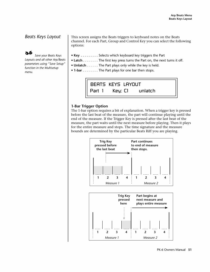
Arp/Beats MenuBeats Keys Layout
Beats Keys Layout This screen assigns the Beats triggers to keyboard notes on the Beats channel. For each Part, Group and Control Key you can select the following options:
____ Save your Beats Keys Layouts and all other Arp/Beats parameters using “Save Setup” function in the Multisetup menu.
• Key . . . . . . . . . Selects which keyboard key triggers the Part• Latch . . . . . . . . The first key press turns the Part on, the next turns it off.• Unlatch . . . . . . The Part plays only while the key is held.• 1-bar . . . . . . . . The Part plays for one bar then stops.
1-Bar Trigger OptionThe 1-bar option requires a bit of explanation. When a trigger key is pressed before the last beat of the measure, the part will continue playing until the end of the measure. If the Trigger Key is pressed after the last beat of the measure, the part waits until the next measure before playing. Then it plays for the entire measure and stops. The time signature and the measure bounds are determined by the particular Beats Riff you are playing.
BEATS KEYS LAYOUTPart 1 Key: C1 unlatch
1 2 3 4 1 2 3 4
Trig Keypressed beforethe last beat
Part continuesto end of measurethen stops.
Measure 1 Measure 2
1 2 3 4 1 2 3 4
Trig Keypressed
here
Part begins atnext measure andplays entire measure
Measure 1 Measure 2
PK-6 Owners Manual 51
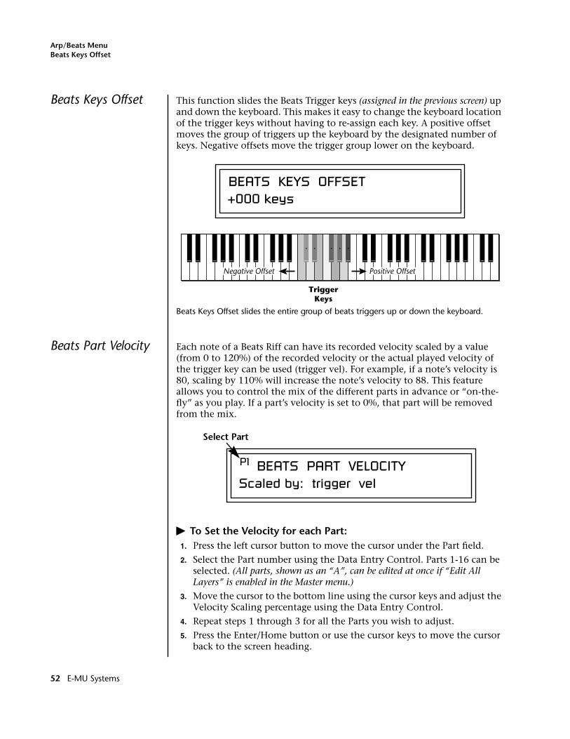
Arp/Beats MenuBeats Keys Offset
Beats Keys Offset This function slides the Beats Trigger keys (assigned in the previous screen) up and down the keyboard. This makes it easy to change the keyboard location of the trigger keys without having to re-assign each key. A positive offset moves the group of triggers up the keyboard by the designated number of keys. Negative offsets move the trigger group lower on the keyboard.
Beats Keys Offset slides the entire group of beats triggers up or down the keyboard.
Beats Part Velocity Each note of a Beats Riff can have its recorded velocity scaled by a value (from 0 to 120%) of the recorded velocity or the actual played velocity of the trigger key can be used (trigger vel). For example, if a note’s velocity is 80, scaling by 110% will increase the note’s velocity to 88. This feature allows you to control the mix of the different parts in advance or “on-the-fly” as you play. If a part’s velocity is set to 0%, that part will be removed from the mix.
� To Set the Velocity for each Part:1. Press the left cursor button to move the cursor under the Part field.
2. Select the Part number using the Data Entry Control. Parts 1-16 can be selected. (All parts, shown as an “A”, can be edited at once if “Edit All Layers” is enabled in the Master menu.)
3. Move the cursor to the bottom line using the cursor keys and adjust the Velocity Scaling percentage using the Data Entry Control.
4. Repeat steps 1 through 3 for all the Parts you wish to adjust.
5. Press the Enter/Home button or use the cursor keys to move the cursor back to the screen heading.
BEATS KEYS OFFSET+000 keys
TriggerKeys
Positive OffsetNegative Offset
P1 BEATS PART VELOCITYScaled by: trigger vel
Select Part
52 E-MU Systems
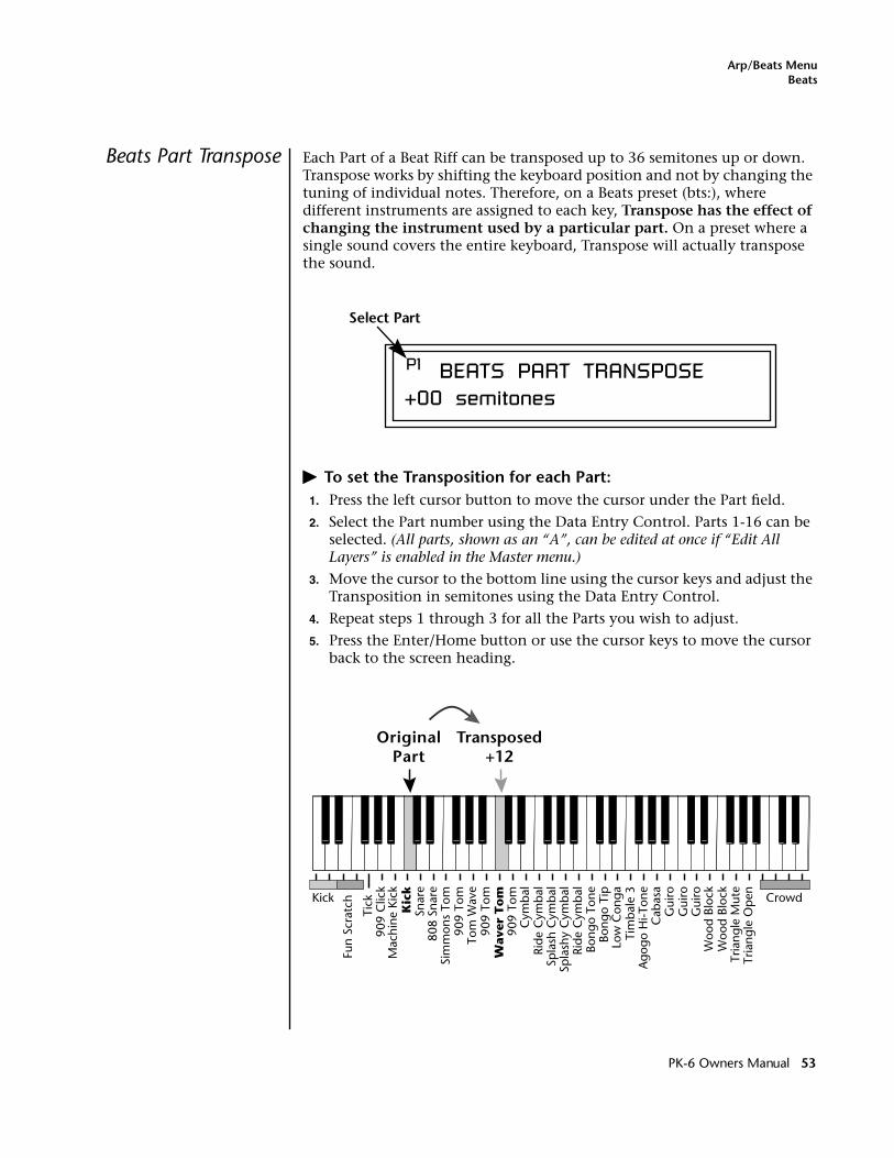
Arp/Beats MenuBeats
Beats Part Transpose Each Part of a Beat Riff can be transposed up to 36 semitones up or down. Transpose works by shifting the keyboard position and not by changing the tuning of individual notes. Therefore, on a Beats preset (bts:), where different instruments are assigned to each key, Transpose has the effect of changing the instrument used by a particular part. On a preset where a single sound covers the entire keyboard, Transpose will actually transpose the sound.
� To set the Transposition for each Part:1. Press the left cursor button to move the cursor under the Part field.
2. Select the Part number using the Data Entry Control. Parts 1-16 can be selected. (All parts, shown as an “A”, can be edited at once if “Edit All Layers” is enabled in the Master menu.)
3. Move the cursor to the bottom line using the cursor keys and adjust the Transposition in semitones using the Data Entry Control.
4. Repeat steps 1 through 3 for all the Parts you wish to adjust.
5. Press the Enter/Home button or use the cursor keys to move the cursor back to the screen heading.
P1 BEATS PART TRANSPOSE+00 semitones
Select Part
Snar
e
Fun
Scra
tch
808
Snar
e
Mac
hine
Kic
kK
ick
Tick
909
Clic
k
Sim
mon
s To
m90
9 To
mTo
m W
ave
909
Tom
Wav
er T
om
909
Tom
Cym
bal
Ride
Cym
bal
Spla
sh C
ymba
lSp
lash
y C
ymba
lRi
de C
ymba
lBo
ngo
Tone
Bong
o Ti
pLo
w C
onga
Tim
bale
3A
gogo
Hi-T
one
Cab
asa
Gui
roG
uiro
Gui
roW
ood
Bloc
kW
ood
Bloc
kTr
iang
le M
ute
Tria
ngle
Op
enKick Crowd
OriginalPart
Transposed+12
PK-6 Owners Manual 53
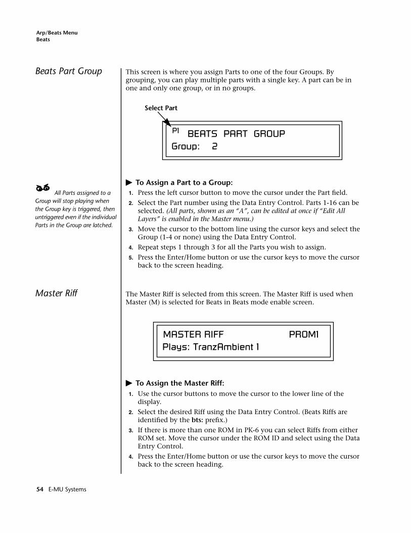
Arp/Beats MenuBeats
Beats Part Group This screen is where you assign Parts to one of the four Groups. By grouping, you can play multiple parts with a single key. A part can be in one and only one group, or in no groups.
� To Assign a Part to a Group:____ All Parts assigned to a Group will stop playing when the Group key is triggered, then untriggered even if the individual Parts in the Group are latched.
1. Press the left cursor button to move the cursor under the Part field.
2. Select the Part number using the Data Entry Control. Parts 1-16 can be selected. (All parts, shown as an “A”, can be edited at once if “Edit All Layers” is enabled in the Master menu.)
3. Move the cursor to the bottom line using the cursor keys and select the Group (1-4 or none) using the Data Entry Control.
4. Repeat steps 1 through 3 for all the Parts you wish to assign.
5. Press the Enter/Home button or use the cursor keys to move the cursor back to the screen heading.
Master Riff The Master Riff is selected from this screen. The Master Riff is used when Master (M) is selected for Beats in Beats mode enable screen.
� To Assign the Master Riff:1. Use the cursor buttons to move the cursor to the lower line of the
display.
2. Select the desired Riff using the Data Entry Control. (Beats Riffs are identified by the bts: prefix.)
3. If there is more than one ROM in PK-6 you can select Riffs from either ROM set. Move the cursor under the ROM ID and select using the Data Entry Control.
4. Press the Enter/Home button or use the cursor keys to move the cursor back to the screen heading.
P1 BEATS PART GROUPGroup: 2
Select Part
MASTER RIFF PROM1Plays: TranzAmbient 1
54 E-MU Systems
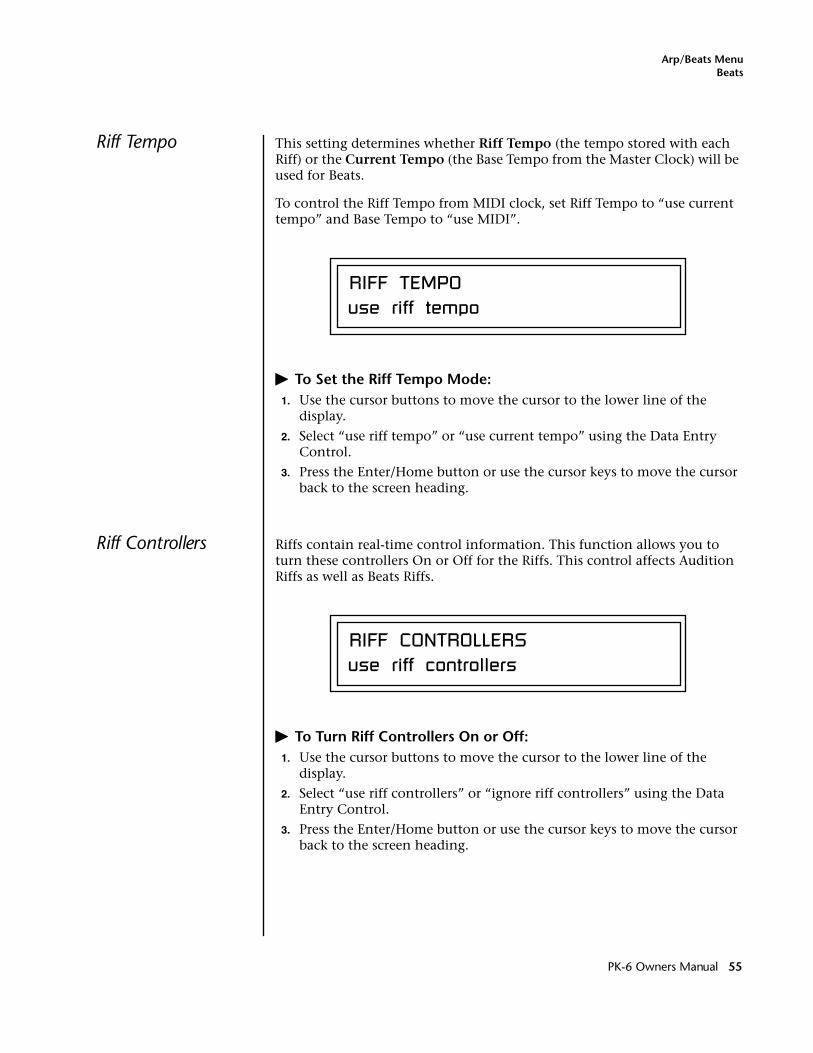
Arp/Beats MenuBeats
Riff Tempo This setting determines whether Riff Tempo (the tempo stored with each Riff) or the Current Tempo (the Base Tempo from the Master Clock) will be used for Beats.
To control the Riff Tempo from MIDI clock, set Riff Tempo to “use current tempo” and Base Tempo to “use MIDI”.
� To Set the Riff Tempo Mode:1. Use the cursor buttons to move the cursor to the lower line of the
display.
2. Select “use riff tempo” or “use current tempo” using the Data Entry Control.
3. Press the Enter/Home button or use the cursor keys to move the cursor back to the screen heading.
Riff Controllers Riffs contain real-time control information. This function allows you to turn these controllers On or Off for the Riffs. This control affects Audition Riffs as well as Beats Riffs.
� To Turn Riff Controllers On or Off:1. Use the cursor buttons to move the cursor to the lower line of the
display.
2. Select “use riff controllers” or “ignore riff controllers” using the Data Entry Control.
3. Press the Enter/Home button or use the cursor keys to move the cursor back to the screen heading.
RIFF TEMPOuse riff tempo
RIFF CONTROLLERSuse riff controllers
PK-6 Owners Manual 55
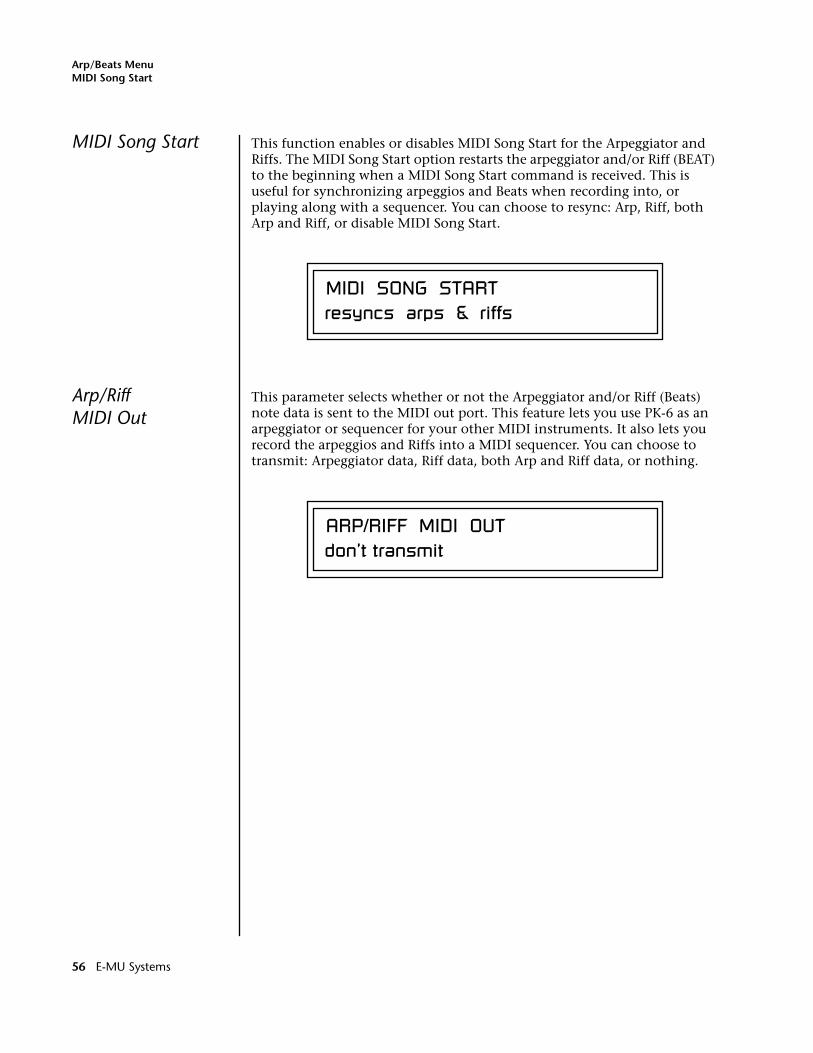
Arp/Beats MenuMIDI Song Start
MIDI Song Start This function enables or disables MIDI Song Start for the Arpeggiator and Riffs. The MIDI Song Start option restarts the arpeggiator and/or Riff (BEAT) to the beginning when a MIDI Song Start command is received. This is useful for synchronizing arpeggios and Beats when recording into, or playing along with a sequencer. You can choose to resync: Arp, Riff, both Arp and Riff, or disable MIDI Song Start.
Arp/RiffMIDI Out
This parameter selects whether or not the Arpeggiator and/or Riff (Beats) note data is sent to the MIDI out port. This feature lets you use PK-6 as an arpeggiator or sequencer for your other MIDI instruments. It also lets you record the arpeggios and Riffs into a MIDI sequencer. You can choose to transmit: Arpeggiator data, Riff data, both Arp and Riff data, or nothing.
MIDI SONG STARTresyncs arps & riffs
ARP/RIFF MIDI OUTdon’t transmit
56 E-MU Systems
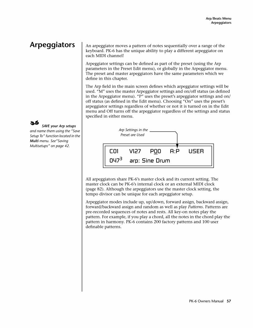
Arp/Beats MenuArpeggiators
Arpeggiators An arpeggiator moves a pattern of notes sequentially over a range of the keyboard. PK-6 has the unique ability to play a different arpeggiator on each MIDI channel!
Arpeggiator settings can be defined as part of the preset (using the Arp parameters in the Preset Edit menu), or globally in the Arpeggiator menu. The preset and master arpeggiators have the same parameters which we define in this chapter.
The Arp field in the main screen defines which arpeggiator settings will be used. “M” uses the master Arpeggiator settings and on/off status (as defined in the Arpeggiator menu). “P” uses the preset’s arpeggiator settings and on/off status (as defined in the Edit menu). Choosing “On” uses the preset’s arpeggiator settings regardless of whether or not it is turned on in the Edit menu and Off turns off the arpeggiator regardless of the settings and status specified in either menu.
____ SAVE your Arp setups and name them using the “Save Setup To” function located in the Multi menu. See“Saving Multisetups” on page 42.
All arpeggiators share PK-6’s master clock and its current setting. The master clock can be PK-6’s internal clock or an external MIDI clock (page 82). Although the arpeggiators use the master clock setting, the tempo divisor can be unique for each arpeggiator setup.
Arpeggiator modes include up, up/down, forward assign, backward assign, forward/backward assign and random as well as play Patterns. Patterns are pre-recorded sequences of notes and rests. All key-on notes play the pattern. For example, if you play a chord, all the notes in the chord play the pattern in harmony. PK-6 contains 200 factory patterns and 100 user definable patterns.
Arp Settings in thePreset are Used
C01 V127 P00 A:P USER
0473 arp: Sine Drum
PK-6 Owners Manual 57
Arp/Beats MenuMaster Arpeggiator Parameters
Arp Controllers The Arpeggiators can be controlled using the front panel real-time controllers or external MIDI continuous controllers. Controllers are patched to Arps via the Preset PatchCords located in the Preset Edit menu. See “Preset Patchcords” on page 165. The following Preset PatchCord destina-tions control the Arpeggiators.
Arpeggiator Resolution (ArpRes)This control changes the Arpeggiator Note Value, which defines the length of the notes when playing arpeggiated chords. It adds to the note value set in the Arpeggiator Note Value screen. See “Note Value” on page 60.
Arpeggiator Extension (ArpExt)This control changes the Arpeggiator Extension Count. It adds to the extension count programmed in the Arpeggiator Note Value screen. See “Extension Count” on page 62.
Arpeggiator Velocity (ArpVel)This control changes the Arpeggiator Velocity Value. It scales the velocity value set in the Arpeggiator Note Value screen. See “Velocity” on page 61.
Arpeggiator Gate (ArpGate)This control changes the Arpeggiator Gate Time. It adds to the gate time set in the Arpeggiator Gate Time screen. See “Gate Time” on page 61.
Arpeggiator Interval (ArpIntvl)This control modulates the Arpeggiator Extension Interval. It adds to the extension programmed in the Arpeggiator Extension Interval screen. See “Extension Interval” on page 62.
Master Arpeggiator Parameters
The Master Arpeggiator is defined in the Arp menu. The Arpeggiator mode selected on the Main Screen determines whether the Master arpeggiator or the Preset menu arpeggiator settings are used.
� To Access the Master Arpeggiator Parameters:
1. Press the Arp menu button lighting the LED. The Arpeggiator menu screen displays the menu page most recently selected since powering up PK-6. The cursor appears below the first character of the screen heading on line one.
2. Use the right cursor button to advance the cursor to the first field in the bottom line of the screen.
3. Now, use the data entry control to access the various Master Arpeggiator parameters.
4. Save your Arpeggiator settings using the “Save Setup” function on the Multi menu.
58 E-MU Systems
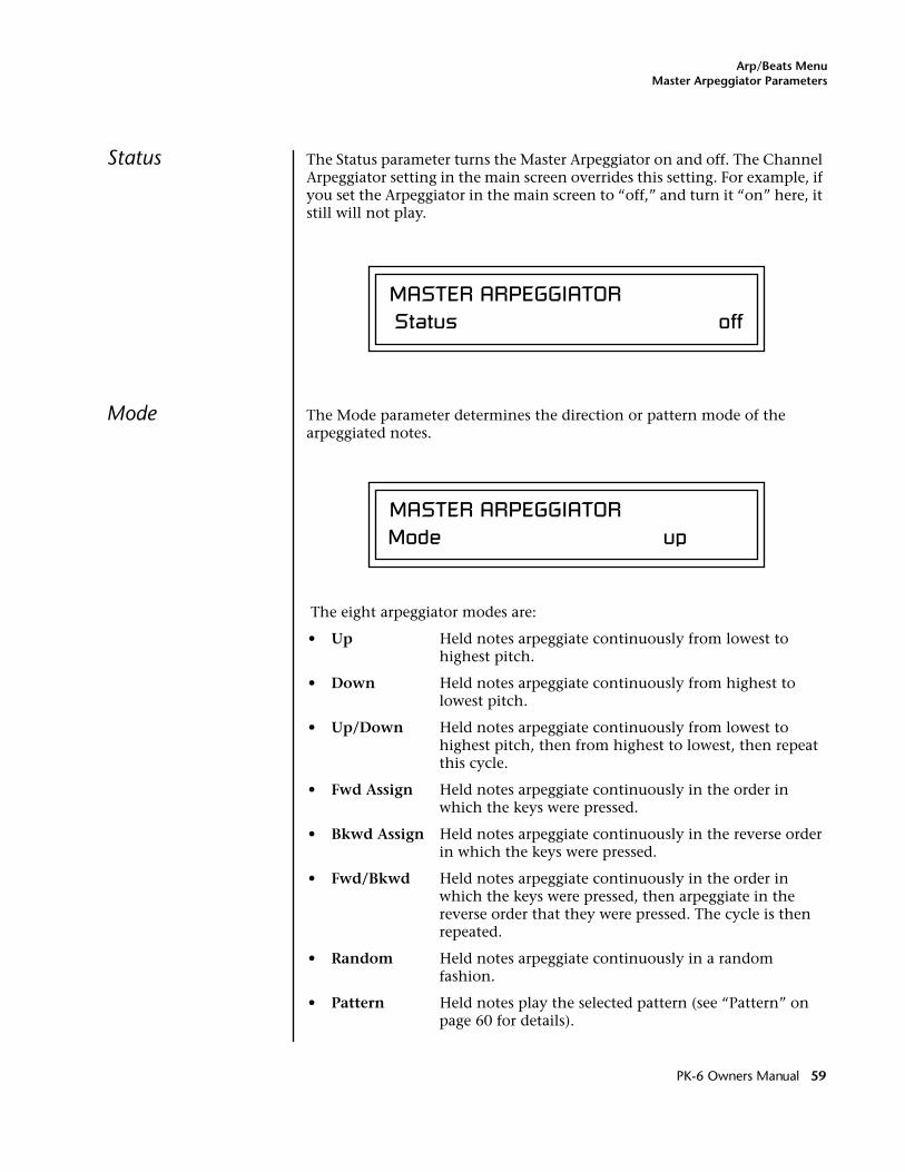
Arp/Beats MenuMaster Arpeggiator Parameters
Status The Status parameter turns the Master Arpeggiator on and off. The Channel Arpeggiator setting in the main screen overrides this setting. For example, if you set the Arpeggiator in the main screen to “off,” and turn it “on” here, it still will not play.
Mode The Mode parameter determines the direction or pattern mode of the arpeggiated notes.
The eight arpeggiator modes are:
• Up Held notes arpeggiate continuously from lowest to highest pitch.
• Down Held notes arpeggiate continuously from highest to lowest pitch.
• Up/Down Held notes arpeggiate continuously from lowest to highest pitch, then from highest to lowest, then repeat this cycle.
• Fwd Assign Held notes arpeggiate continuously in the order in which the keys were pressed.
• Bkwd Assign Held notes arpeggiate continuously in the reverse order in which the keys were pressed.
• Fwd/Bkwd Held notes arpeggiate continuously in the order in which the keys were pressed, then arpeggiate in the reverse order that they were pressed. The cycle is then repeated.
• Random Held notes arpeggiate continuously in a random fashion.
• Pattern Held notes play the selected pattern (see “Pattern” on page 60 for details).
MASTER ARPEGGIATOR Status off
MASTER ARPEGGIATORMode up
PK-6 Owners Manual 59
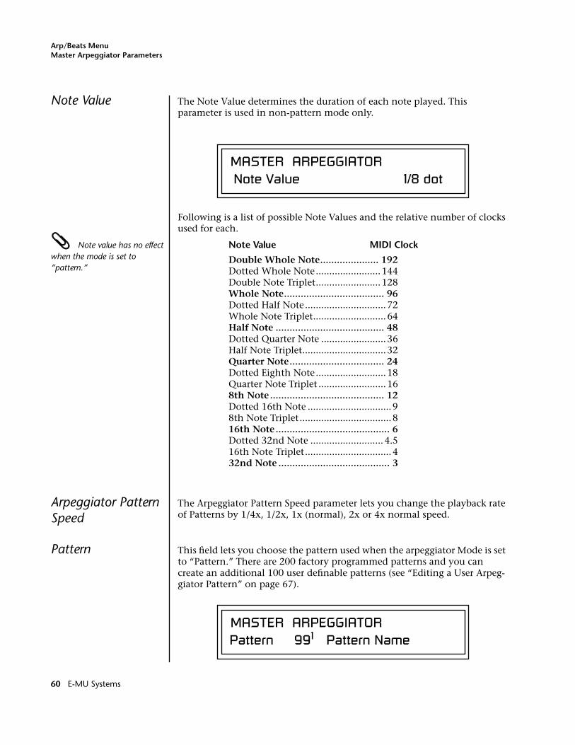
Arp/Beats MenuMaster Arpeggiator Parameters
Note Value The Note Value determines the duration of each note played. This parameter is used in non-pattern mode only.
Following is a list of possible Note Values and the relative number of clocks used for each.
Note value has no effect when the mode is set to “pattern.”
Note Value MIDI Clock
Double Whole Note..................... 192 Dotted Whole Note........................ 144Double Note Triplet........................ 128Whole Note.................................... 96Dotted Half Note.............................. 72Whole Note Triplet........................... 64Half Note ....................................... 48Dotted Quarter Note ........................ 36Half Note Triplet............................... 32Quarter Note.................................. 24Dotted Eighth Note.......................... 18Quarter Note Triplet ......................... 168th Note......................................... 12Dotted 16th Note ............................... 9 8th Note Triplet.................................. 816th Note......................................... 6Dotted 32nd Note ........................... 4.516th Note Triplet................................ 432nd Note ........................................ 3
Arpeggiator Pattern Speed
The Arpeggiator Pattern Speed parameter lets you change the playback rate of Patterns by 1/4x, 1/2x, 1x (normal), 2x or 4x normal speed.
Pattern This field lets you choose the pattern used when the arpeggiator Mode is set to “Pattern.” There are 200 factory programmed patterns and you can create an additional 100 user definable patterns (see “Editing a User Arpeg-giator Pattern” on page 67).
MASTER ARPEGGIATOR Note Value 1/8 dot
MASTER ARPEGGIATORPattern 991 Pattern Name
60 E-MU Systems
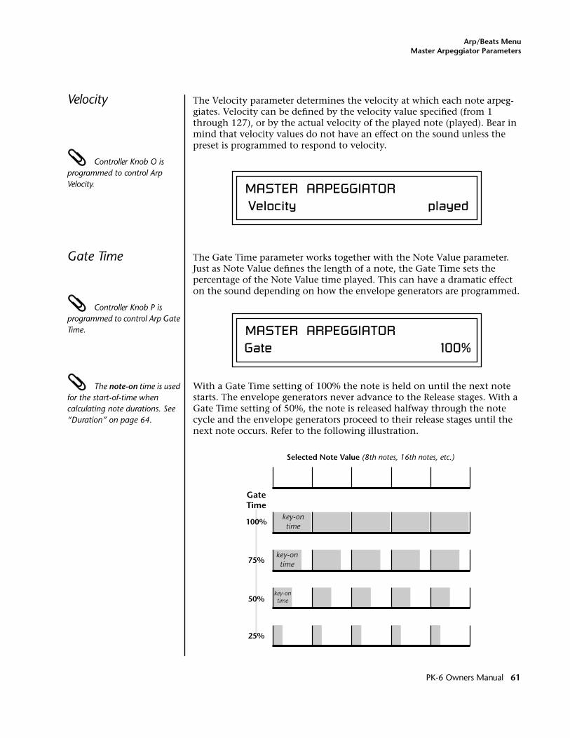
Arp/Beats MenuMaster Arpeggiator Parameters
Velocity The Velocity parameter determines the velocity at which each note arpeg-giates. Velocity can be defined by the velocity value specified (from 1 through 127), or by the actual velocity of the played note (played). Bear in mind that velocity values do not have an effect on the sound unless the preset is programmed to respond to velocity.
Controller Knob O is programmed to control Arp Velocity.
Gate Time The Gate Time parameter works together with the Note Value parameter. Just as Note Value defines the length of a note, the Gate Time sets the percentage of the Note Value time played. This can have a dramatic effect on the sound depending on how the envelope generators are programmed.
Controller Knob P is programmed to control Arp Gate Time.
The note-on time is used for the start-of-time when calculating note durations. See “Duration” on page 64.
With a Gate Time setting of 100% the note is held on until the next note starts. The envelope generators never advance to the Release stages. With a Gate Time setting of 50%, the note is released halfway through the note cycle and the envelope generators proceed to their release stages until the next note occurs. Refer to the following illustration.
MASTER ARPEGGIATOR Velocity played
MASTER ARPEGGIATORGate 100%
GateTime
100%
Selected Note Value (8th notes, 16th notes, etc.)
75%
50%
25%
key-ontime
key-ontime
key-ontime
PK-6 Owners Manual 61
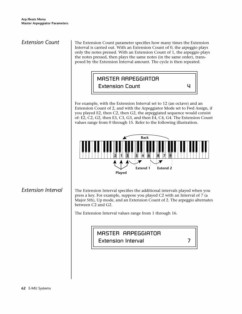
Arp/Beats MenuMaster Arpeggiator Parameters
Extension Count The Extension Count parameter specifies how many times the Extension Interval is carried out. With an Extension Count of 0, the arpeggio plays only the notes pressed. With an Extension Count of 1, the arpeggio plays the notes pressed, then plays the same notes (in the same order), trans-posed by the Extension Interval amount. The cycle is then repeated.
For example, with the Extension Interval set to 12 (an octave) and an Extension Count of 2, and with the Arpeggiator Mode set to Fwd Assign, if you played E2, then C2, then G2, the arpeggiated sequence would consist of: E2, C2, G2, then E3, C3, G3, and then E4, C4, G4. The Extension Count values range from 0 through 15. Refer to the following illustration.
Extension Interval The Extension Interval specifies the additional intervals played when you press a key. For example, suppose you played C2 with an Interval of 7 (a Major 5th), Up mode, and an Extension Count of 2. The arpeggio alternates between C2 and G2.
The Extension Interval values range from 1 through 16.
MASTER ARPEGGIATOR Extension Count 4
12 3 45 6 78 9
Extend 1
Back
PlayedExtend 2
MASTER ARPEGGIATOR Extension Interval 7
62 E-MU Systems
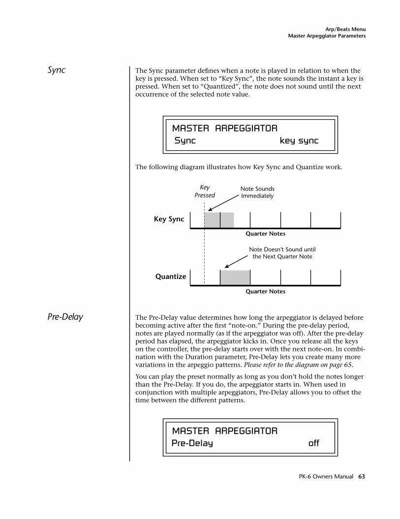
Arp/Beats MenuMaster Arpeggiator Parameters
Sync The Sync parameter defines when a note is played in relation to when the key is pressed. When set to “Key Sync”, the note sounds the instant a key is pressed. When set to “Quantized”, the note does not sound until the next occurrence of the selected note value.
The following diagram illustrates how Key Sync and Quantize work.
Pre-Delay The Pre-Delay value determines how long the arpeggiator is delayed before becoming active after the first “note-on.” During the pre-delay period, notes are played normally (as if the arpeggiator was off). After the pre-delay period has elapsed, the arpeggiator kicks in. Once you release all the keys on the controller, the pre-delay starts over with the next note-on. In combi-nation with the Duration parameter, Pre-Delay lets you create many more variations in the arpeggio patterns. Please refer to the diagram on page 65.
You can play the preset normally as long as you don’t hold the notes longer than the Pre-Delay. If you do, the arpeggiator starts in. When used in conjunction with multiple arpeggiators, Pre-Delay allows you to offset the time between the different patterns.
MASTER ARPEGGIATOR Sync key sync
Quarter Notes
Quarter Notes
Key Sync
KeyPressed
Quantize
Note SoundsImmediately
Note Doesn't Sound untilthe Next Quarter Note
MASTER ARPEGGIATORPre-Delay off
PK-6 Owners Manual 63
Arp/Beats MenuMaster Arpeggiator Parameters
Duration This parameter defines how long the arpeggiator plays before stopping. The Duration is specified in note values. Therefore if an arpeggio were running at a 16th Note Value and the Duration were set to a whole note, the arpeg-giator would play 16 steps before stopping. After the duration has elapsed, the arpeggiator remains inactive until the key is released. If Duration is set to Off, the arpeggio repeats as long as the notes are held (Infinite Duration).
Duration can be used to modify the patterns and increase the possible pattern combinations and variations. Because this parameter limits the length of arpeggiator play time, it can change the arpeggio pattern when the Duration is less than the length of the arpeggio. You can set the arpeggio to repeat continuously using the Recycle function described below.
Post-Delay This parameter is only relevant when both the “Duration” and “Recycle” parameters are not in the “Off” state. The Post-Delay value determines how long the arpeggiator is delayed after the Duration period. Please refer to the diagram on page 65. During the post-delay period, notes are played normally (as if the arpeggiator was off). After the post-delay period has elapsed, the arpeggiator either jumps to the beginning of the Pre-Delay period or to the beginning of the Duration period depending on the Recycle setting.
If the arpeggiator is playing an extension when the Duration expires, the notes in the extension will continue to sound during the Post-Delay (and Pre-Delay if on). On the next pass through the Duration period, the extension continues where it left off.
Post-Delay increases the number of possible variations in the beat and allows the recycle loop to be set to an exact measure of time.
MASTER ARPEGGIATORDuration 1 / 1d
MASTER ARPEGGIATORPost-Delay off
64 E-MU Systems
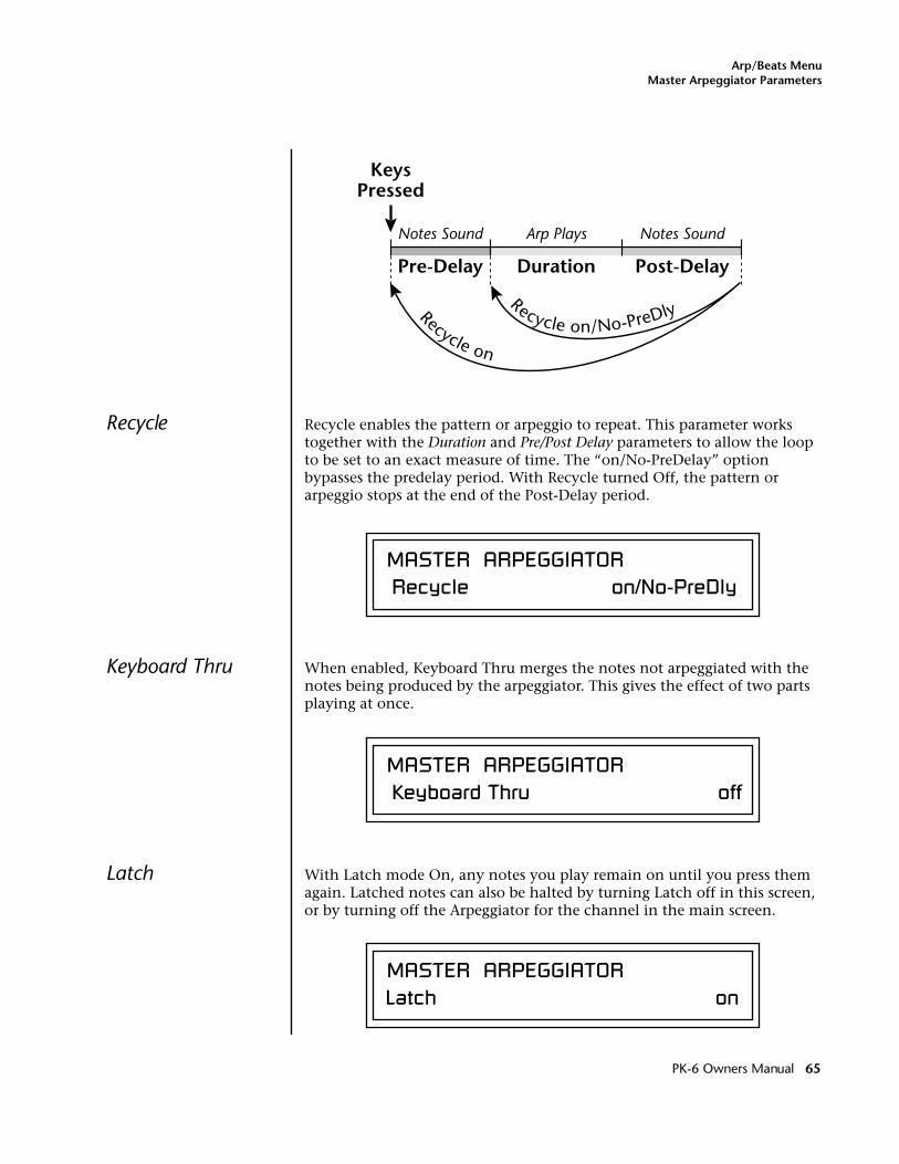
Arp/Beats MenuMaster Arpeggiator Parameters
Recycle Recycle enables the pattern or arpeggio to repeat. This parameter works together with the Duration and Pre/Post Delay parameters to allow the loop to be set to an exact measure of time. The “on/No-PreDelay” option bypasses the predelay period. With Recycle turned Off, the pattern or arpeggio stops at the end of the Post-Delay period.
Keyboard Thru When enabled, Keyboard Thru merges the notes not arpeggiated with the notes being produced by the arpeggiator. This gives the effect of two parts playing at once.
Latch With Latch mode On, any notes you play remain on until you press them again. Latched notes can also be halted by turning Latch off in this screen, or by turning off the Arpeggiator for the channel in the main screen.
KeysPressed
Arp PlaysNotes Sound Notes Sound
Pre-Delay Duration Post-Delay
Recycle on
Recycle on/No-PreDly
MASTER ARPEGGIATOR Recycle on/No-PreDly
MASTER ARPEGGIATOR Keyboard Thru off
MASTER ARPEGGIATORLatch on
PK-6 Owners Manual 65
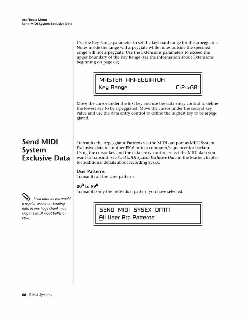
Arp/Beats MenuSend MIDI System Exclusive Data
Use the Key Range parameter to set the keyboard range for the arpeggiator. Notes inside the range will arpeggiate while notes outside the specified range will not arpeggiate. Use the Extensions parameters to exceed the upper boundary of the Key Range (see the information about Extensions beginning on page 62).
Move the cursor under the first key and use the data entry control to define the lowest key to be arpeggiated. Move the cursor under the second key value and use the data entry control to define the highest key to be arpeg-giated.
Send MIDI System Exclusive Data
Transmits the Arpeggiator Patterns via the MIDI out port as MIDI System Exclusive data to another PK-6 or to a computer/sequencer for backup. Using the cursor key and the data entry control, select the MIDI data you want to transmit. See Send MIDI System Exclusive Data in the Master chapter for additional details about recording SysEx.
User PatternsTransmits all the User patterns.
000 to 990
Transmits only the individual pattern you have selected.
Send data as you would a regular sequence. Sending data in one huge chunk may clog the MIDI input buffer on PK-6.
MASTER ARPEGGIATORKey Range C-2->G8
SEND MIDI SYSEX DATAAll User Arp Patterns
66 E-MU Systems
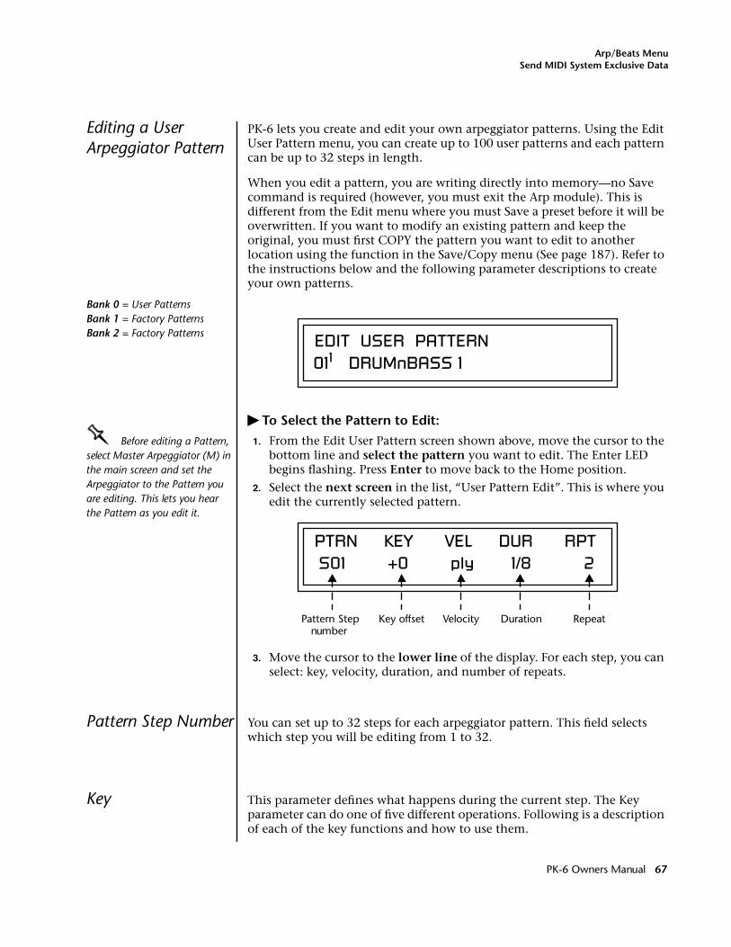
Arp/Beats MenuSend MIDI System Exclusive Data
Editing a User Arpeggiator Pattern
PK-6 lets you create and edit your own arpeggiator patterns. Using the Edit User Pattern menu, you can create up to 100 user patterns and each pattern can be up to 32 steps in length.
When you edit a pattern, you are writing directly into memory—no Save command is required (however, you must exit the Arp module). This is different from the Edit menu where you must Save a preset before it will be overwritten. If you want to modify an existing pattern and keep the original, you must first COPY the pattern you want to edit to another location using the function in the Save/Copy menu (See page 187). Refer to the instructions below and the following parameter descriptions to create your own patterns.
Bank 0 = User PatternsBank 1 = Factory PatternsBank 2 = Factory Patterns
� To Select the Pattern to Edit:
OOOO Before editing a Pattern, select Master Arpeggiator (M) in the main screen and set the Arpeggiator to the Pattern you are editing. This lets you hear the Pattern as you edit it.
1. From the Edit User Pattern screen shown above, move the cursor to the bottom line and select the pattern you want to edit. The Enter LED begins flashing. Press Enter to move back to the Home position.
2. Select the next screen in the list, “User Pattern Edit”. This is where you edit the currently selected pattern.
3. Move the cursor to the lower line of the display. For each step, you can select: key, velocity, duration, and number of repeats.
Pattern Step Number You can set up to 32 steps for each arpeggiator pattern. This field selects which step you will be editing from 1 to 32.
Key This parameter defines what happens during the current step. The Key parameter can do one of five different operations. Following is a description of each of the key functions and how to use them.
EDIT USER PATTERN011 DRUMnBASS 1
PTRN KEY VEL DUR RPT S01 +0 ply 1/8 2
Pattern Step number
Key offset Velocity Duration Repeat
PK-6 Owners Manual 67
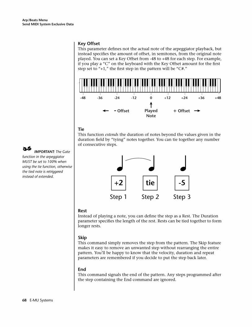
Arp/Beats MenuSend MIDI System Exclusive Data
Key OffsetThis parameter defines not the actual note of the arpeggiator playback, but instead specifies the amount of offset, in semitones, from the original note played. You can set a Key Offset from -48 to +48 for each step. For example, if you play a “C” on the keyboard with the Key Offset amount for the first step set to “+1,” the first step in the pattern will be “C#.”
TieThis function extends the duration of notes beyond the values given in the duration field by “tying” notes together. You can tie together any number of consecutive steps.
____ IMPORTANT: The Gate function in the arpeggiator MUST be set to 100% when using the tie function, otherwise the tied note is retriggered instead of extended.
RestInstead of playing a note, you can define the step as a Rest. The Duration parameter specifies the length of the rest. Rests can be tied together to form longer rests.
SkipThis command simply removes the step from the pattern. The Skip feature makes it easy to remove an unwanted step without rearranging the entire pattern. You’ll be happy to know that the velocity, duration and repeat parameters are remembered if you decide to put the step back later.
EndThis command signals the end of the pattern. Any steps programmed after the step containing the End command are ignored.
PlayedNote
+ OffsetOffset
+12-12 0 +24-24 +36-36-48 +48
+2
Step 1
tie
Step 2
-5
Step 3
68 E-MU Systems
Arp/Beats MenuSend MIDI System Exclusive Data
Velocity Each note in the pattern plays using either a preset velocity value (from 1 through 127), or using the actual velocity of the played note (ply).
Note: Velocity values will not have an effect on the sound unless velocity is programmed to do something in the preset.
Duration This parameter sets the length of time for the current step, defined as a note value, based on the Master Tempo. The selectable note durations are described below.
Repeat Each step can be played from 1 to 32 times. A repeat setting of “1” indicates the step will be played one time (not repeated one time or played twice).
� To Edit a User Pattern:
1. The first field in the Edit User Pattern field defines the pattern’s step number. Start with the pattern Step 01.
2. Define the Key Offset, Velocity, Duration and Repeat values.
3. Repeat steps 1 and 2 until you have setup the desired number of steps in the pattern.
4. Set the Key Offset to “End” on the last step in the pattern.
1/32 32nd Note1/16t 16th Note Triplet1/32d Dotted 32nd Note1/16 16th Note1/8t 8th Note Triplet1/16d Dotted 16th Note 1/8 8th Note1/4t Quarter Note Triplet1/8d Dotted Eighth Note1/4 Quarter Note
1/2t Half Note Triplet1/4d Dotted Quarter Note1/2 Half Note1/1d Dotted Whole Note1/1t Whole Note Triplet1/2d Dotted Half Note1/1 Whole Note2/1t Double Whole Note
Triplet2/1 Double Whole Note
PK-6 Owners Manual 69
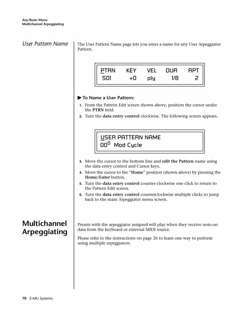
Arp/Beats MenuMultichannel Arpeggiating
User Pattern Name The User Pattern Name page lets you enter a name for any User Arpeggiator Pattern.
� To Name a User Pattern:
1. From the Pattern Edit screen shown above, position the cursor under the PTRN field.
2. Turn the data entry control clockwise. The following screen appears.
3. Move the cursor to the bottom line and edit the Pattern name using the data entry control and Cursor keys.
4. Move the cursor to the “Home” position (shown above) by pressing the Home/Enter button.
5. Turn the data entry control counter-clockwise one click to return to the Pattern Edit screen.
6. Turn the data entry control counterclockwise multiple clicks to jump back to the main Arpeggiator menu screen.
Multichannel Arpeggiating
Presets with the arpeggiator assigned will play when they receive note-on data from the keyboard or external MIDI source.
Please refer to the instructions on page 26 to learn one way to perform using multiple arpeggiators.
PTRN KEY VEL DUR RPT S01 +0 ply 1/8 2
USER PATTERN NAME000 Mod Cycle
70 E-MU Systems
Controllers Menu
The Controllers menu contains functions related to the keyboard, knobs or trigger buttons of PK-6. For example, the Command Function Trigger Keys are programmed in this menu. All Controllers menu data is saved with the Multisetup. See page 41 for more information about Multisetups.
� To enable the Controllers menu:Press the Controllers button, lighting the LED. The Controllers Menu screen displays the menu page most recently selected since powering up PK-6. The cursor appears below the first character of the screen heading on line one.
� To select a new screen:Press the Home/Enter button or press the Cursor button repeatedly until the cursor is below the screen title heading. Rotate the data entry control to select another screen.
� To modify a parameter:Press either Cursor button repeatedly (or hold down the right cursor button while turning the data entry control) until the cursor is below the desired parameter value. Rotate the data entry control to change the value.
� To return to the previously selected Mode/View screen:Press the Controllers button, turning off the LED.
PK-6 Owners Manual 71
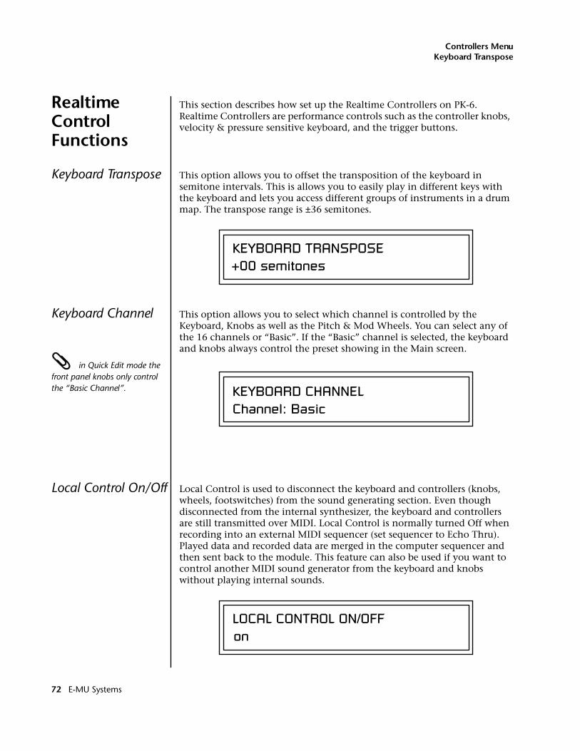
Controllers MenuKeyboard Transpose
Realtime Control Functions
This section describes how set up the Realtime Controllers on PK-6. Realtime Controllers are performance controls such as the controller knobs, velocity & pressure sensitive keyboard, and the trigger buttons.
Keyboard Transpose This option allows you to offset the transposition of the keyboard in semitone intervals. This is allows you to easily play in different keys with the keyboard and lets you access different groups of instruments in a drum map. The transpose range is ±36 semitones.
Keyboard Channel This option allows you to select which channel is controlled by the Keyboard, Knobs as well as the Pitch & Mod Wheels. You can select any of the 16 channels or “Basic”. If the “Basic” channel is selected, the keyboard and knobs always control the preset showing in the Main screen.
in Quick Edit mode the front panel knobs only control the “Basic Channel”.
Local Control On/Off Local Control is used to disconnect the keyboard and controllers (knobs, wheels, footswitches) from the sound generating section. Even though disconnected from the internal synthesizer, the keyboard and controllers are still transmitted over MIDI. Local Control is normally turned Off when recording into an external MIDI sequencer (set sequencer to Echo Thru). Played data and recorded data are merged in the computer sequencer and then sent back to the module. This feature can also be used if you want to control another MIDI sound generator from the keyboard and knobs without playing internal sounds.
KEYBOARD TRANSPOSE+00 semitones
KEYBOARD CHANNELChannel: Basic
LOCAL CONTROL ON/OFFon
72 E-MU Systems
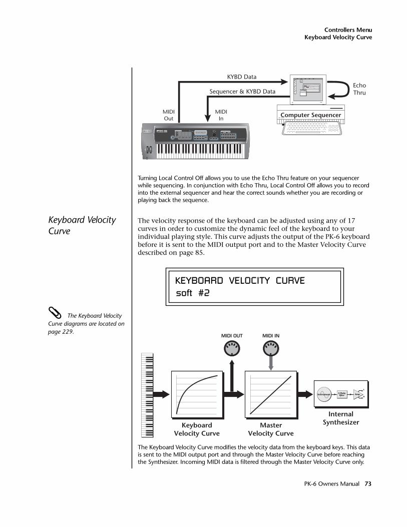
Controllers MenuKeyboard Velocity Curve
Turning Local Control Off allows you to use the Echo Thru feature on your sequencer while sequencing. In conjunction with Echo Thru, Local Control Off allows you to record into the external sequencer and hear the correct sounds whether you are recording or playing back the sequence.
Keyboard Velocity Curve
The velocity response of the keyboard can be adjusted using any of 17 curves in order to customize the dynamic feel of the keyboard to your individual playing style. This curve adjusts the output of the PK-6 keyboard before it is sent to the MIDI output port and to the Master Velocity Curve described on page 85.
The Keyboard Velocity Curve diagrams are located on page 229.
The Keyboard Velocity Curve modifies the velocity data from the keyboard keys. This data is sent to the MIDI output port and through the Master Velocity Curve before reaching the Synthesizer. Incoming MIDI data is filtered through the Master Velocity Curve only.
CO 1A Vo l 1 27 Pan00R SU ER0322 bas : I n t e r f e r ence
MIDIOut
MIDIIn
KEYBOARD VELOCITY CURVEsoft #2
KeyboardVelocity Curve
MasterVelocity Curve
InternalSynthesizer
MIDI OUT MIDI IN
Instrument Amp
L
R
Z-PlaneFilter
PK-6 Owners Manual 73
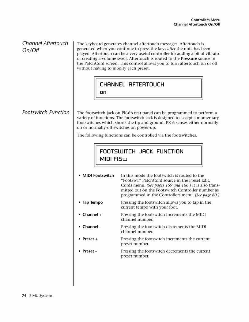
Controllers MenuChannel Aftertouch On/Off
Channel Aftertouch On/Off
The keyboard generates channel aftertouch messages. Aftertouch is generated when you continue to press the keys after the note has been played. Aftertouch can be a very useful controller for adding a bit of vibrato or creating a volume swell. Aftertouch is routed to the Pressure source in the PatchCord screen. This control allows you to turn aftertouch on or off without having to modify each preset.
Footswitch Function The footswitch jack on PK-6’s rear panel can be programmed to perform a variety of functions. The footswitch jack is designed to accept a momentary footswitches which shorts the tip and ground. PK-6 senses either normally-on or normally-off switches on power-up.
The following functions can be controlled via the footswitches.
• MIDI Footswitch In this mode the footswitch is routed to the “FootSw1” PatchCord source in the Preset Edit, Cords menu. (See pages 159 and 166.) It is also trans-mitted out on the Footswitch Controller number as programmed in the Controllers menu. (See page 80.)
• Tap Tempo Pressing the footswitch allows you to tap in the current tempo with your foot.
• Channel + Pressing the footswitch increments the MIDI channel number.
• Channel - Pressing the footswitch decrements the MIDI channel number.
• Preset + Pressing the footswitch increments the current preset number.
• Preset - Pressing the footswitch decrements the current preset number.
CHANNEL AFTERTOUCHon
FOOTSWITCH JACK FUNCTIONMIDI FtSw
74 E-MU Systems
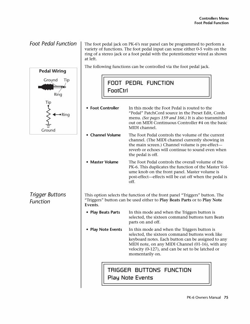
Controllers MenuFoot Pedal Function
Foot Pedal Function The foot pedal jack on PK-6’s rear panel can be programmed to perform a variety of functions. The foot pedal input can sense either 0-5 volts on the ring of a stereo jack or a foot pedal with the potentiometer wired as shown at left.
The following functions can be controlled via the foot pedal jack.
• Foot Controller In this mode the Foot Pedal is routed to the “Pedal” PatchCord source in the Preset Edit, Cords menu. (See pages 159 and 166.) It is also transmitted out on MIDI Continuous Controller #4 on the basic MIDI channel.
• Channel Volume The Foot Pedal controls the volume of the current channel. (The MIDI channel currently showing in the main screen.) Channel volume is pre-effect— reverb or echoes will continue to sound even when the pedal is off.
• Master Volume The Foot Pedal controls the overall volume of the PK-6. This duplicates the function of the Master Vol-ume knob on the front panel. Master volume is post-effect—effects will be cut off when the pedal is off.
Trigger Buttons Function
This option selects the function of the front panel “Triggers” button. The “Triggers” button can be used either to Play Beats Parts or to Play Note Events.
• Play Beats Parts In this mode and when the Triggers button is selected, the sixteen command buttons turn Beats parts on and off.
• Play Note Events In this mode and when the Triggers button is selected, the sixteen command buttons work like keyboard notes. Each button can be assigned to any MIDI note, on any MIDI Channel (01-16), with any velocity (0-127), and can be set to be latched or momentarily on.
Ground Tip
Ring
Ground
Tip
Ring
Pedal Wiring
FOOT PEDAL FUNCTIONFootCtrl
TRIGGER BUTTONS FUNCTIONPlay Note Events
PK-6 Owners Manual 75
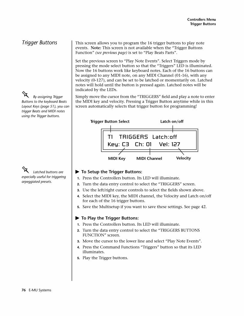
Controllers MenuTrigger Buttons
Trigger Buttons This screen allows you to program the 16 trigger buttons to play note events. Note: This screen is not available when the “Trigger Buttons Function” (see previous page) is set to “Play Beats Parts”.
Set the previous screen to “Play Note Events”. Select Triggers mode by pressing the mode select button so that the “Triggers” LED is illuminated. Now the 16 buttons work like keyboard notes. Each of the 16 buttons can be assigned to any MIDI note, on any MIDI Channel (01-16), with any velocity (0-127), and can be set to be latched or momentarily on. Latched notes will hold until the button is pressed again. Latched notes will be indicated by the LEDs.
OOOO By assigning Trigger Buttons to the keyboard Beats Layout Keys (page 51), you can trigger Beats and MIDI notes using the Trigger buttons.
Simply move the cursor from the “TRIGGERS” field and play a note to enter the MIDI key and velocity. Pressing a Trigger Button anytime while in this screen automatically selects that trigger button for programming!
OOOO Latched buttons are especially useful for triggering arpeggiated presets.
� To Setup the Trigger Buttons:1. Press the Controllers button. Its LED will illuminate.
2. Turn the data entry control to select the “TRIGGERS” screen.
3. Use the left/right cursor controls to select the fields shown above.
4. Select the MIDI key, the MIDI channel, the Velocity and Latch on/off for each of the 16 trigger buttons.
5. Save the Multisetup if you want to save these settings. See page 42.
� To Play the Trigger Buttons:1. Press the Controllers button. Its LED will illuminate.
2. Turn the data entry control to select the “TRIGGERS BUTTONS FUNCTION” screen.
3. Move the cursor to the lower line and select “Play Note Events”.
4. Press the Command Functions “Triggers” button so that its LED illuminates.
5. Play the Trigger buttons.
T1 TRIGGERS Latch:off Key: C3 Ch: 01 Vel: 127
Trigger Button Select Latch on/off
MIDI Key MIDI Channel Velocity
76 E-MU Systems
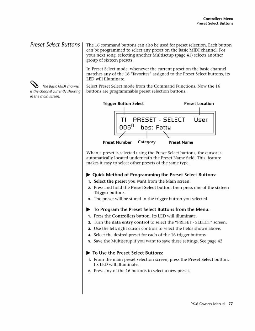
Controllers MenuPreset Select Buttons
Preset Select Buttons The 16 command buttons can also be used for preset selection. Each button can be programmed to select any preset on the Basic MIDI channel. For your next song, selecting another Multisetup (page 41) selects another group of sixteen presets.
In Preset Select mode, whenever the current preset on the basic channel matches any of the 16 “favorites” assigned to the Preset Select buttons, its LED will illuminate.
The Basic MIDI channel is the channel currently showing in the main screen.
Select Preset Select mode from the Command Functions. Now the 16 buttons are programmable preset selection buttons.
When a preset is selected using the Preset Select buttons, the cursor is automatically located underneath the Preset Name field. This feature makes it easy to select other presets of the same type.
� Quick Method of Programming the Preset Select Buttons:1. Select the preset you want from the Main screen.
2. Press and hold the Preset Select button, then press one of the sixteen Trigger buttons.
3. The preset will be stored in the trigger button you selected.
� To Program the Preset Select Buttons from the Menu:1. Press the Controllers button. Its LED will illuminate.
2. Turn the data entry control to select the “PRESET - SELECT” screen.
3. Use the left/right cursor controls to select the fields shown above.
4. Select the desired preset for each of the 16 trigger buttons.
5. Save the Multisetup if you want to save these settings. See page 42.
� To Use the Preset Select Buttons:1. From the main preset selection screen, press the Preset Select button.
Its LED will illuminate.
2. Press any of the 16 buttons to select a new preset.
T1 PRESET - SELECT User0060 bas: Fatty
Trigger Button Select Preset Location
Preset Number Preset NameCategory
PK-6 Owners Manual 77
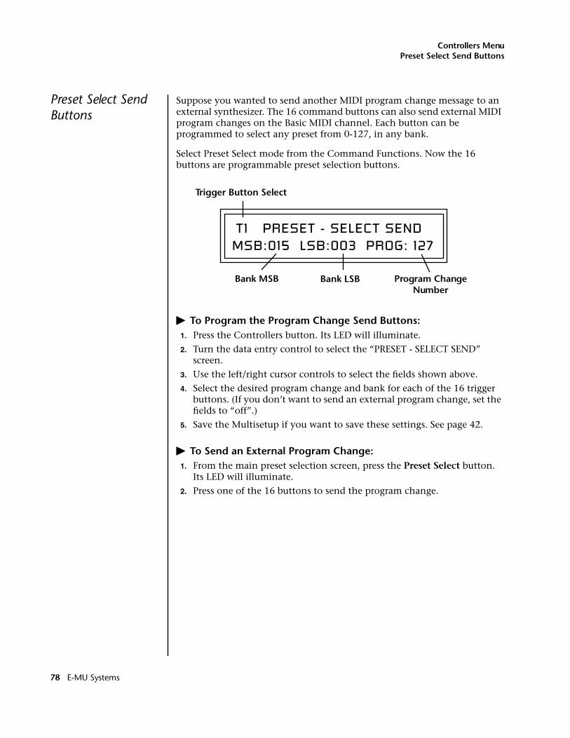
Controllers MenuPreset Select Send Buttons
Preset Select Send Buttons
Suppose you wanted to send another MIDI program change message to an external synthesizer. The 16 command buttons can also send external MIDI program changes on the Basic MIDI channel. Each button can be programmed to select any preset from 0-127, in any bank.
Select Preset Select mode from the Command Functions. Now the 16 buttons are programmable preset selection buttons.
� To Program the Program Change Send Buttons:1. Press the Controllers button. Its LED will illuminate.
2. Turn the data entry control to select the “PRESET - SELECT SEND” screen.
3. Use the left/right cursor controls to select the fields shown above.
4. Select the desired program change and bank for each of the 16 trigger buttons. (If you don’t want to send an external program change, set the fields to “off”.)
5. Save the Multisetup if you want to save these settings. See page 42.
� To Send an External Program Change:1. From the main preset selection screen, press the Preset Select button.
Its LED will illuminate.
2. Press one of the 16 buttons to send the program change.
T1 PRESET - SELECT SENDMSB:015 LSB:003 PROG: 127
Trigger Button Select
Bank MSB Program Change Number
Bank LSB
78 E-MU Systems
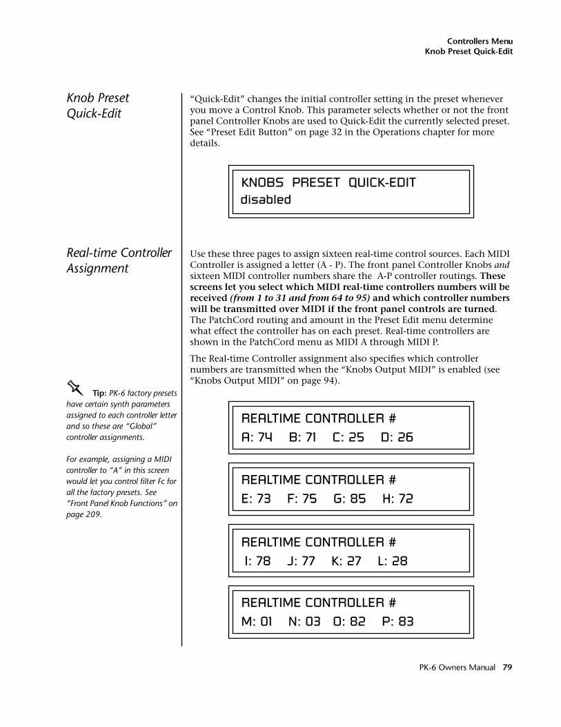
Controllers MenuKnob Preset Quick-Edit
Knob Preset Quick-Edit
“Quick-Edit” changes the initial controller setting in the preset whenever you move a Control Knob. This parameter selects whether or not the front panel Controller Knobs are used to Quick-Edit the currently selected preset. See “Preset Edit Button” on page 32 in the Operations chapter for more details.
Real-time Controller Assignment
Use these three pages to assign sixteen real-time control sources. Each MIDI Controller is assigned a letter (A - P). The front panel Controller Knobs and sixteen MIDI controller numbers share the A-P controller routings. These screens let you select which MIDI real-time controllers numbers will be received (from 1 to 31 and from 64 to 95) and which controller numbers will be transmitted over MIDI if the front panel controls are turned. The PatchCord routing and amount in the Preset Edit menu determine what effect the controller has on each preset. Real-time controllers are shown in the PatchCord menu as MIDI A through MIDI P.
The Real-time Controller assignment also specifies which controller numbers are transmitted when the “Knobs Output MIDI” is enabled (see “Knobs Output MIDI” on page 94).
OOOO Tip: PK-6 factory presets have certain synth parameters assigned to each controller letter and so these are “Global” controller assignments.
For example, assigning a MIDI controller to “A” in this screen would let you control filter Fc for all the factory presets. See “Front Panel Knob Functions” on page 209.
KNOBS PRESET QUICK-EDITdisabled
REALTIME CONTROLLER #A: 74 B: 71 C: 25 D: 26
REALTIME CONTROLLER #E: 73 F: 75 G: 85 H: 72
REALTIME CONTROLLER # I: 78 J: 77 K: 27 L: 28
REALTIME CONTROLLER #M: 01 N: 03 O: 82 P: 83
PK-6 Owners Manual 79
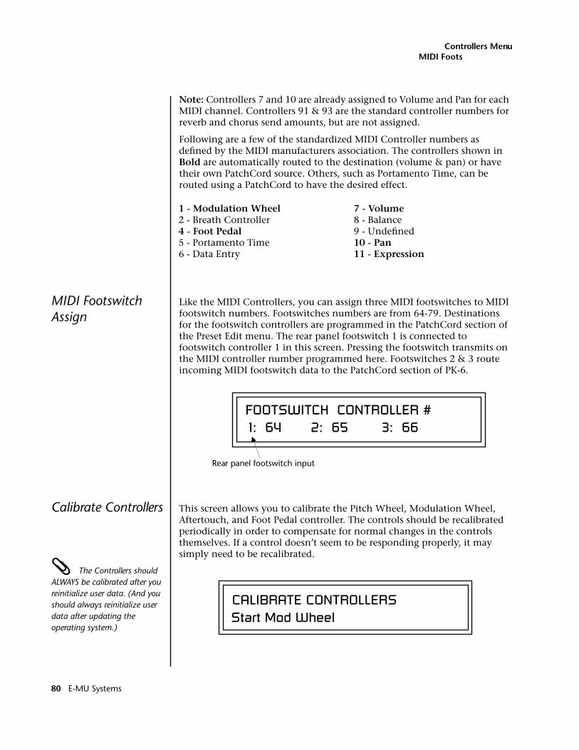
Controllers MenuMIDI Footswitch Assign
Note: Controllers 7 and 10 are already assigned to Volume and Pan for each MIDI channel. Controllers 91 & 93 are the standard controller numbers for reverb and chorus send amounts, but are not assigned.
Following are a few of the standardized MIDI Controller numbers as defined by the MIDI manufacturers association. The controllers shown in Bold are automatically routed to the destination (volume & pan) or have their own PatchCord source. Others, such as Portamento Time, can be routed using a PatchCord to have the desired effect.
MIDI Footswitch Assign
Like the MIDI Controllers, you can assign three MIDI footswitches to MIDI footswitch numbers. Footswitches numbers are from 64-79. Destinations for the footswitch controllers are programmed in the PatchCord section of the Preset Edit menu. The rear panel footswitch 1 is connected to footswitch controller 1 in this screen. Pressing the footswitch transmits on the MIDI controller number programmed here. Footswitches 2 & 3 route incoming MIDI footswitch data to the PatchCord section of PK-6.
Calibrate Controllers This screen allows you to calibrate the Pitch Wheel, Modulation Wheel, Aftertouch, and Foot Pedal controller. The controls should be recalibrated periodically in order to compensate for normal changes in the controls themselves. If a control doesn’t seem to be responding properly, it may simply need to be recalibrated.
The Controllers should ALWAYS be calibrated after you reinitialize user data. (And you should always reinitialize user data after updating the operating system.)
1 - Modulation Wheel2 - Breath Controller4 - Foot Pedal5 - Portamento Time6 - Data Entry
7 - Volume8 - Balance9 - Undefined10 - Pan11 - Expression
FOOTSWITCH CONTROLLER # 1: 64 2: 65 3: 66
Rear panel footswitch input
CALIBRATE CONTROLLERSStart Mod Wheel
80 E-MU Systems
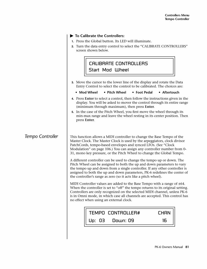
Controllers MenuTempo Controller
� To Calibrate the Controllers:1. Press the Global button. Its LED will illuminate.
2. Turn the data entry control to select the “CALIBRATE CONTROLLERS” screen shown below.
3. Move the cursor to the lower line of the display and rotate the Data Entry Control to select the control to be calibrated. The choices are:
• Mod Wheel • Pitch Wheel • Foot Pedal • Aftertouch
4. Press Enter to select a control, then follow the instructions given in the display. You will be asked to mover the control through its entire range (minimum through maximum), then press Enter.
5. In the case of the Pitch Wheel, you first move the wheel through its min-max range and leave the wheel resting in its center position. Then press Enter.
Tempo Controller This function allows a MIDI controller to change the Base Tempo of the Master Clock. The Master Clock is used by the arpeggiators, clock divisor PatchCords, tempo-based envelopes and synced LFOs. (See “Clock Modulation” on page 106.) You can assign any controller number from 0-31, mono key pressure, or the Pitch Wheel to change the Global Tempo.
A different controller can be used to change the tempo up or down. The Pitch Wheel can be assigned to both the up and down parameters to vary the tempo up and down from a single controller. If any other controller is assigned to both the up and down parameters, PK-6 redefines the center of the controller’s range as zero (so it acts like a pitch wheel).
MIDI Controller values are added to the Base Tempo with a range of ±64. When the controller is set to “off” the tempo returns to its original setting. Controllers are only recognized on the selected MIDI channel, unless PK-6 is in Omni mode, in which case all channels are accepted. This control has no effect when using an external clock.
CALIBRATE CONTROLLERSStart Mod Wheel
TEMPO CONTROLLER# CHAN
Up: 03 Down: 09 16
PK-6 Owners Manual 81
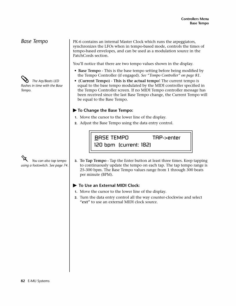
Controllers MenuBase Tempo
Base Tempo PK-6 contains an internal Master Clock which runs the arpeggiators, synchronizes the LFOs when in tempo-based mode, controls the times of tempo-based envelopes, and can be used as a modulation source in the PatchCords section.
You’ll notice that there are two tempo values shown in the display.
• Base Tempo - This is the base tempo setting before being modified by the Tempo Controller (if engaged). See “Tempo Controller” on page 81.
The Arp/Beats LED flashes in time with the Base Tempo.
• (Current Tempo) - This is the actual tempo! The current tempo is equal to the base tempo modulated by the MIDI controller specified in the Tempo Controller screen. If no MIDI Tempo controller message has been received since the last Base Tempo change, the Current Tempo will be equal to the Base Tempo.
� To Change the Base Tempo:
1. Move the cursor to the lower line of the display.
2. Adjust the Base Tempo using the data entry control.
OOOO You can also tap tempo using a footswitch. See page 74.
3. To Tap Tempo - Tap the Enter button at least three times. Keep tapping to continuously update the tempo on each tap. The tap tempo range is 25-300 bpm. The Base Tempo values range from 1 through 300 beats per minute (BPM).
� To Use an External MIDI Clock:1. Move the cursor to the lower line of the display.
2. Turn the data entry control all the way counter-clockwise and select “ext” to use an external MIDI clock source.
BASE TEMPO TAP->enter 120 bpm (current: 182)
82 E-MU Systems
Global Menu
The Global menu contains functions that affect the overall operation of PK-6. For example, changing the Master Tune parameter changes the tuning of all the presets, not just the one currently displayed.
� To enable the Global menu:Press the Global button, lighting the LED. The Global Menu screen displays the menu page most recently selected since powering up PK-6. The cursor appears below the first character of the screen heading on line one.
____ Warning: Global Menu changes are automatically saved when you exit the menu. If the power is turned off before you exit the menu any changes you have made will be lost.
� To select a new screen:Press the Home/Enter button or press the Cursor button repeatedly until the cursor is below the screen title heading. Rotate the data entry control to select another screen.
� To modify a parameter:Press either Cursor button repeatedly (or hold down the right cursor button while turning the data entry control) until the cursor is below the desired parameter value. Rotate the data entry control to change the value.
� To return to the previously selected screen:Press the Global button, turning off the LED.
PK-6 Owners Manual 83
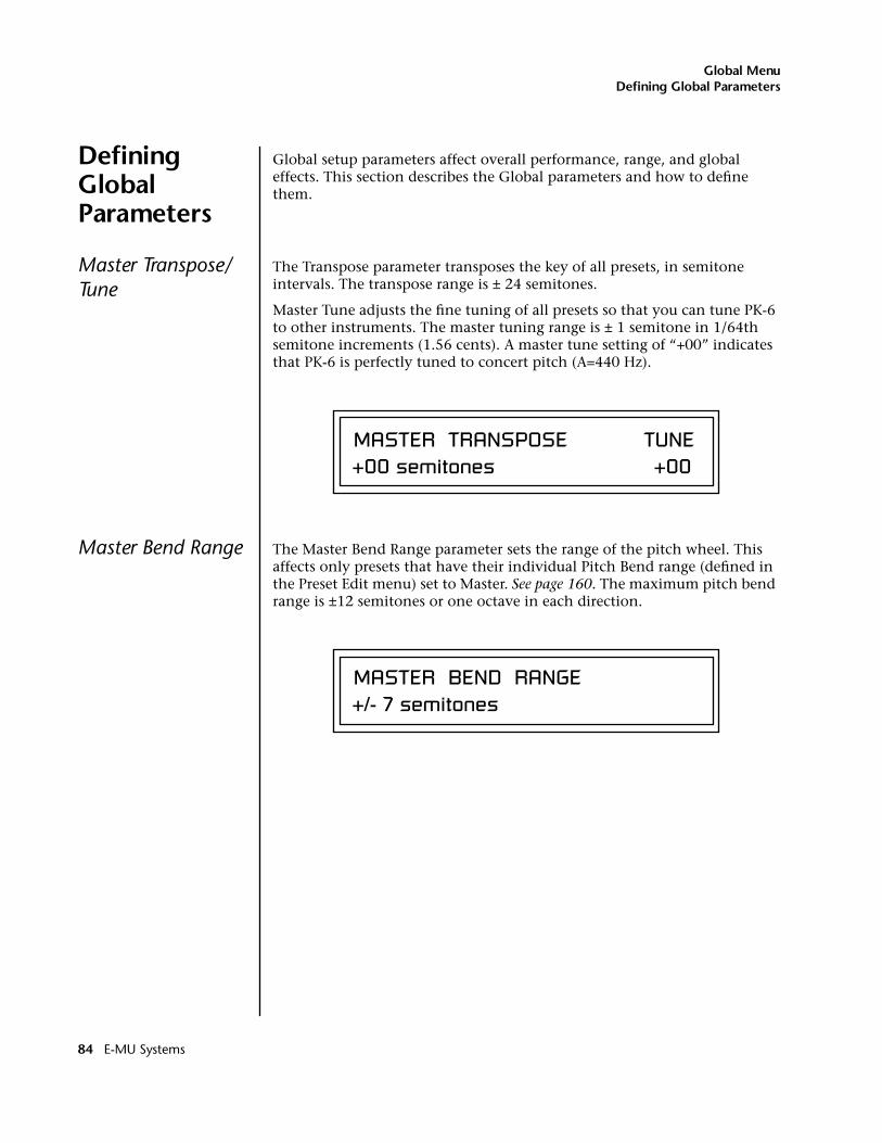
Global MenuDefining Global Parameters
Defining Global Parameters
Global setup parameters affect overall performance, range, and global effects. This section describes the Global parameters and how to define them.
Master Transpose/Tune
The Transpose parameter transposes the key of all presets, in semitone intervals. The transpose range is ± 24 semitones.
Master Tune adjusts the fine tuning of all presets so that you can tune PK-6 to other instruments. The master tuning range is ± 1 semitone in 1/64th semitone increments (1.56 cents). A master tune setting of “+00” indicates that PK-6 is perfectly tuned to concert pitch (A=440 Hz).
Master Bend Range The Master Bend Range parameter sets the range of the pitch wheel. This affects only presets that have their individual Pitch Bend range (defined in the Preset Edit menu) set to Master. See page 160. The maximum pitch bend range is ±12 semitones or one octave in each direction.
MASTER TRANSPOSE TUNE+00 semitones +00
MASTER BEND RANGE+/- 7 semitones
84 E-MU Systems
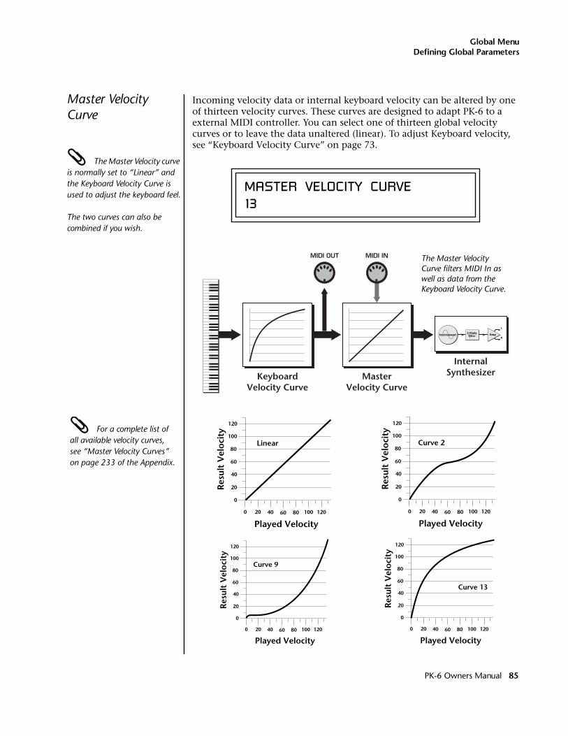
Global MenuDefining Global Parameters
Master Velocity Curve
Incoming velocity data or internal keyboard velocity can be altered by one of thirteen velocity curves. These curves are designed to adapt PK-6 to a external MIDI controller. You can select one of thirteen global velocity curves or to leave the data unaltered (linear). To adjust Keyboard velocity, see “Keyboard Velocity Curve” on page 73.
The Master Velocity curve is normally set to “Linear” and the Keyboard Velocity Curve is used to adjust the keyboard feel.
The two curves can also be combined if you wish.
For a complete list of all available velocity curves, see “Master Velocity Curves” on page 233 of the Appendix.
MASTER VELOCITY CURVE13
KeyboardVelocity Curve
MasterVelocity Curve
InternalSynthesizer
MIDI OUT MIDI IN
Instrument Amp
L
R
Z-PlaneFilter
The Master Velocity Curve filters MIDI In as well as data from the Keyboard Velocity Curve.
Linear
0
20
40
60
80
100
120
0 20 40 60 80 100
Played Velocity120
Res
ult
Vel
oci
ty
Curve 2
0
20
40
60
80
100
120
0 20 40 60 80 100
Played Velocity120
Res
ult
Vel
oci
ty
0
20
40
60
80
100
120
0 20 40 60 80 100
Played Velocity120
Res
ult
Vel
oci
ty
Curve 9
0
20
40
60
80
100
120
0 20 40 60 80 100
Played Velocity120
Res
ult
Vel
oci
ty
Curve 13
PK-6 Owners Manual 85
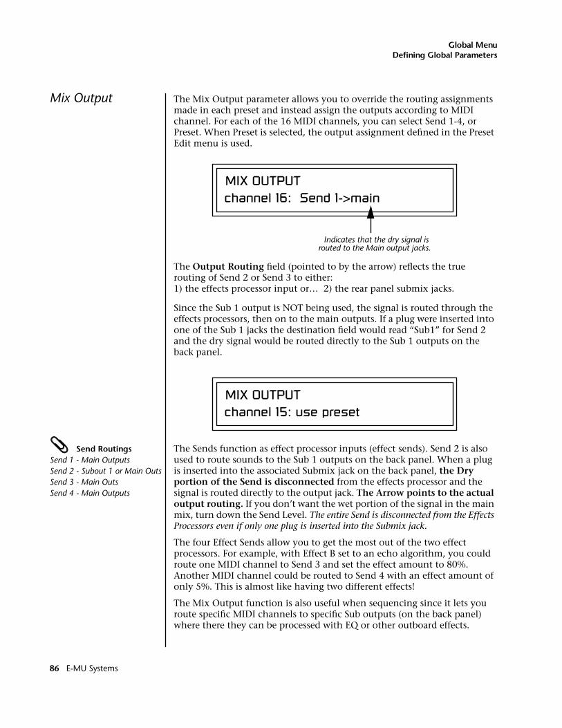
Global MenuDefining Global Parameters
Mix Output The Mix Output parameter allows you to override the routing assignments made in each preset and instead assign the outputs according to MIDI channel. For each of the 16 MIDI channels, you can select Send 1-4, or Preset. When Preset is selected, the output assignment defined in the Preset Edit menu is used.
The Output Routing field (pointed to by the arrow) reflects the true routing of Send 2 or Send 3 to either:1) the effects processor input or… 2) the rear panel submix jacks.
Since the Sub 1 output is NOT being used, the signal is routed through the effects processors, then on to the main outputs. If a plug were inserted into one of the Sub 1 jacks the destination field would read “Sub1” for Send 2 and the dry signal would be routed directly to the Sub 1 outputs on the back panel.
Send RoutingsSend 1 - Main OutputsSend 2 - Subout 1 or Main OutsSend 3 - Main OutsSend 4 - Main Outputs
The Sends function as effect processor inputs (effect sends). Send 2 is also used to route sounds to the Sub 1 outputs on the back panel. When a plug is inserted into the associated Submix jack on the back panel, the Dry portion of the Send is disconnected from the effects processor and the signal is routed directly to the output jack. The Arrow points to the actual output routing. If you don’t want the wet portion of the signal in the main mix, turn down the Send Level. The entire Send is disconnected from the Effects Processors even if only one plug is inserted into the Submix jack.
The four Effect Sends allow you to get the most out of the two effect processors. For example, with Effect B set to an echo algorithm, you could route one MIDI channel to Send 3 and set the effect amount to 80%. Another MIDI channel could be routed to Send 4 with an effect amount of only 5%. This is almost like having two different effects!
The Mix Output function is also useful when sequencing since it lets you route specific MIDI channels to specific Sub outputs (on the back panel) where there they can be processed with EQ or other outboard effects.
channel 16: Send 1->mainMIX OUTPUT
Indicates that the dry signal isrouted to the Main output jacks.
channel 15: use presetMIX OUTPUT
86 E-MU Systems
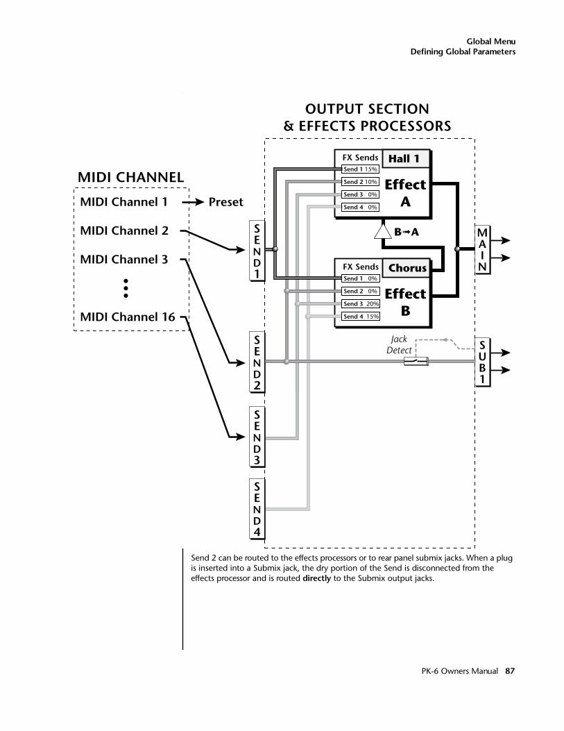
Global MenuDefining Global Parameters
Send 2 can be routed to the effects processors or to rear panel submix jacks. When a plug is inserted into a Submix jack, the dry portion of the Send is disconnected from the effects processor and is routed directly to the Submix output jacks.
MIDI Channel 1
MIDI Channel 2
MIDI Channel 3
MIDI Channel 16
MIDI CHANNEL
Preset
SEND1
SUB1
MAIN
OUTPUT SECTION& EFFECTS PROCESSORS
Hall 1
EffectA
Chorus
EffectB
B➟A
JackDetect
FX Sends
Send 2 10%
Send 3 0%
Send 4 0%
Send 1 15%
FX SendsSend 1 0%
Send 4 15%
Send 3 20%
Send 2 0%
SEND2
SEND4
SEND3
PK-6 Owners Manual 87
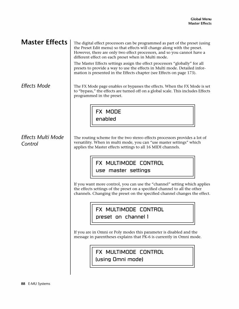
Global MenuMaster Effects
Master Effects The digital effect processors can be programmed as part of the preset (using the Preset Edit menu) so that effects will change along with the preset. However, there are only two effect processors, and so you cannot have a different effect on each preset when in Multi mode.
The Master Effects settings assign the effect processors “globally” for all presets to provide a way to use the effects in Multi mode. Detailed infor-mation is presented in the Effects chapter (see Effects on page 173).
Effects Mode The FX Mode page enables or bypasses the effects. When the FX Mode is set to “bypass,” the effects are turned off on a global scale. This includes Effects programmed in the preset.
Effects Multi Mode Control
The routing scheme for the two stereo effects processors provides a lot of versatility. When in multi mode, you can “use master settings” which applies the Master effects settings to all 16 MIDI channels.
If you want more control, you can use the “channel” setting which applies the effects settings of the preset on a specified channel to all the other channels. Changing the preset on the specified channel changes the effect.
If you are in Omni or Poly modes this parameter is disabled and the message in parentheses explains that PK-6 is currently in Omni mode.
FX MODEenabled
FX MULTIMODE CONTROLuse master settings
FX MULTIMODE CONTROLpreset on channel 1
FX MULTIMODE CONTROL(using Omni mode)
88 E-MU Systems
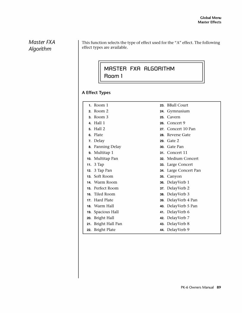
Global MenuMaster Effects
Master FXA Algorithm
This function selects the type of effect used for the “A” effect. The following effect types are available.
A Effect Types
MASTER FXA ALGORITHMRoom 1
1. Room 1
2. Room 2
3. Room 3
4. Hall 1
5. Hall 2
6. Plate
7. Delay
8. Panning Delay
9. Multitap 1
10. Multitap Pan
11. 3 Tap
12. 3 Tap Pan
13. Soft Room
14. Warm Room
15. Perfect Room
16. Tiled Room
17. Hard Plate
18. Warm Hall
19. Spacious Hall
20. Bright Hall
21. Bright Hall Pan
22. Bright Plate
23. BBall Court
24. Gymnasium
25. Cavern
26. Concert 9
27. Concert 10 Pan
28. Reverse Gate
29. Gate 2
30. Gate Pan
31. Concert 11
32. Medium Concert
33. Large Concert
34. Large Concert Pan
35. Canyon
36. DelayVerb 1
37. DelayVerb 2
38. DelayVerb 3
39. DelayVerb 4 Pan
40. DelayVerb 5 Pan
41. DelayVerb 6
42. DelayVerb 7
43. DelayVerb 8
44. DelayVerb 9
PK-6 Owners Manual 89
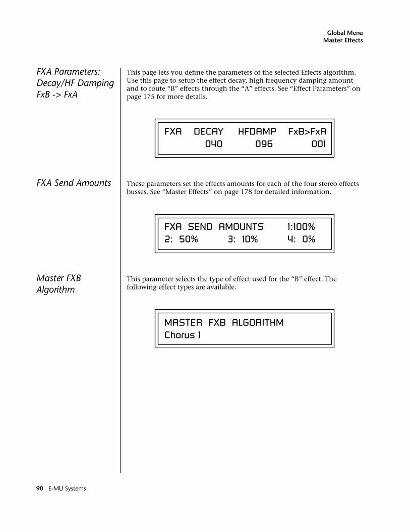
Global MenuMaster Effects
FXA Parameters: Decay/HF Damping FxB -> FxA
This page lets you define the parameters of the selected Effects algorithm. Use this page to setup the effect decay, high frequency damping amount and to route “B” effects through the “A” effects. See “Effect Parameters” on page 175 for more details.
FXA Send Amounts These parameters set the effects amounts for each of the four stereo effects busses. See “Master Effects” on page 178 for detailed information.
Master FXB Algorithm
This parameter selects the type of effect used for the “B” effect. The following effect types are available.
FXA DECAY HFDAMP FxB>FxA 040 096 001
FXA SEND AMOUNTS 1:100% 2: 50% 3: 10% 4: 0%
MASTER FXB ALGORITHMChorus 1
90 E-MU Systems
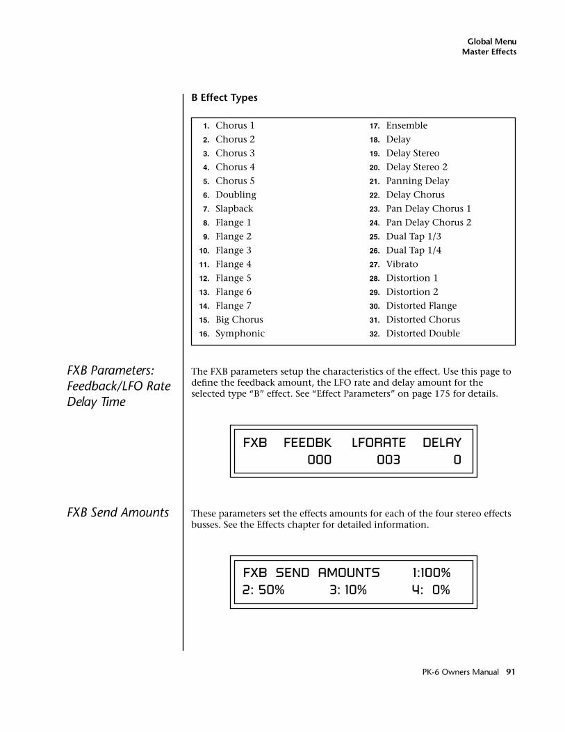
Global MenuMaster Effects
B Effect Types
FXB Parameters: Feedback/LFO Rate Delay Time
The FXB parameters setup the characteristics of the effect. Use this page to define the feedback amount, the LFO rate and delay amount for the selected type “B” effect. See “Effect Parameters” on page 175 for details.
FXB Send Amounts These parameters set the effects amounts for each of the four stereo effects busses. See the Effects chapter for detailed information.
1. Chorus 1
2. Chorus 2
3. Chorus 3
4. Chorus 4
5. Chorus 5
6. Doubling
7. Slapback
8. Flange 1
9. Flange 2
10. Flange 3
11. Flange 4
12. Flange 5
13. Flange 6
14. Flange 7
15. Big Chorus
16. Symphonic
17. Ensemble
18. Delay
19. Delay Stereo
20. Delay Stereo 2
21. Panning Delay
22. Delay Chorus
23. Pan Delay Chorus 1
24. Pan Delay Chorus 2
25. Dual Tap 1/3
26. Dual Tap 1/4
27. Vibrato
28. Distortion 1
29. Distortion 2
30. Distorted Flange
31. Distorted Chorus
32. Distorted Double
FXB FEEDBK LFORATE DELAY 000 003 0
FXB SEND AMOUNTS 1:100% 2: 50% 3: 10% 4: 0%
PK-6 Owners Manual 91
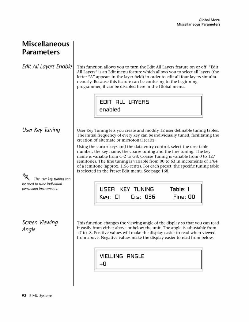
Global MenuMiscellaneous Parameters
MiscellaneousParameters
Edit All Layers Enable This function allows you to turn the Edit All Layers feature on or off. “Edit All Layers” is an Edit menu feature which allows you to select all layers (the letter “A” appears in the layer field) in order to edit all four layers simulta-neously. Because this feature can be confusing to the beginning programmer, it can be disabled here in the Global menu.
User Key Tuning User Key Tuning lets you create and modify 12 user definable tuning tables. The initial frequency of every key can be individually tuned, facilitating the creation of alternate or microtonal scales.
Using the cursor keys and the data entry control, select the user table number, the key name, the coarse tuning and the fine tuning. The key name is variable from C-2 to G8. Coarse Tuning is variable from 0 to 127 semitones. The fine tuning is variable from 00 to 63 in increments of 1/64 of a semitone (approx. 1.56 cents). For each preset, the specific tuning table is selected in the Preset Edit menu. See page 168.
OOOO The user key tuning can be used to tune individual percussion instruments.
Screen Viewing Angle
This function changes the viewing angle of the display so that you can read it easily from either above or below the unit. The angle is adjustable from +7 to -8. Positive values will make the display easier to read when viewed from above. Negative values make the display easier to read from below.
EDIT ALL LAYERSenabled
USER KEY TUNING Table: 1Key: C1 Crs: 036 Fine: 00
VIEWING ANGLE+0
92 E-MU Systems
MIDI Menu
Most of the parameters in PK-6 that relate to MIDI are contained within this menu. You can merge MIDI data, change the continuous controller assignments, turn program changes off or on, and lots more.
MIDI menu settings are saved with the current Multimap.
� To enable the MIDI menu:Press the MIDI button, lighting the LED. The MIDI Menu screen displays the menu page most recently selected since powering up PK-6. The cursor appears below the first character of the screen heading on line one.
____ Warning: MIDI Menu changes are automatically saved when you exit the menu. If the power is turned off before you exit the menu any changes you have made will be lost.
� To select a new screen:Press the Home/Enter button or press the Cursor button repeatedly until the cursor is below the screen title heading. Rotate the data entry control to select another screen.
� To modify a parameter:Press either Cursor button repeatedly (or hold down the right cursor button while turning the data entry control) until the cursor is below the desired parameter value. Rotate the data entry control to change the value.
� To return to the previously selected Mode/View screen:Press the MIDI button, turning off the LED.
PK-6 Owners Manual 93
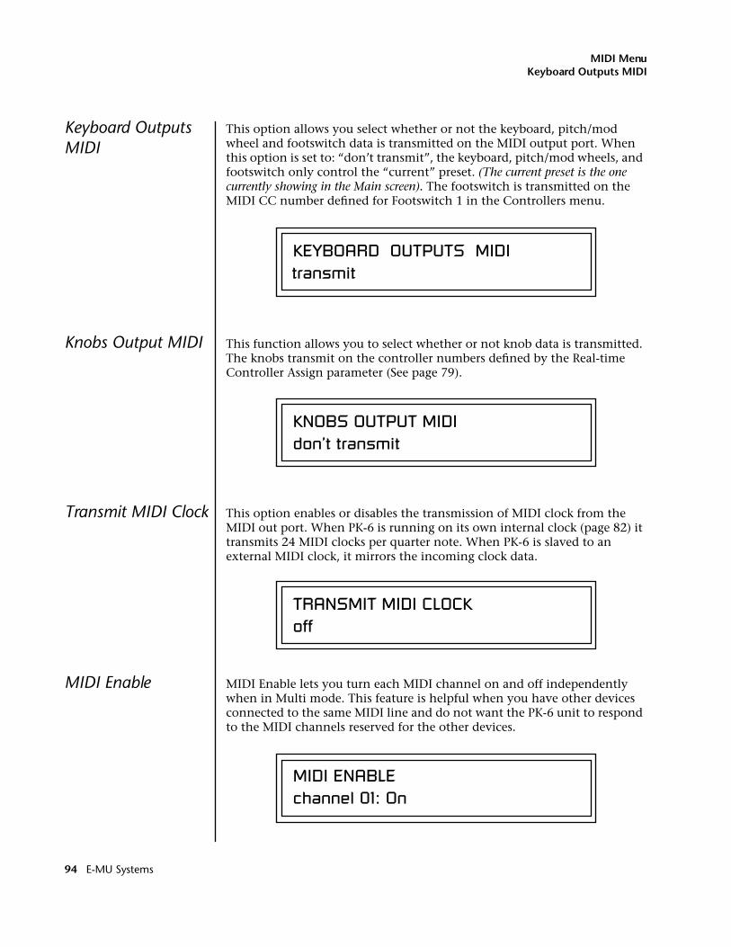
MIDI MenuKeyboard Outputs MIDI
Keyboard Outputs MIDI
This option allows you select whether or not the keyboard, pitch/mod wheel and footswitch data is transmitted on the MIDI output port. When this option is set to: “don’t transmit”, the keyboard, pitch/mod wheels, and footswitch only control the “current” preset. (The current preset is the one currently showing in the Main screen). The footswitch is transmitted on the MIDI CC number defined for Footswitch 1 in the Controllers menu.
Knobs Output MIDI This function allows you to select whether or not knob data is transmitted. The knobs transmit on the controller numbers defined by the Real-time Controller Assign parameter (See page 79).
Transmit MIDI Clock This option enables or disables the transmission of MIDI clock from the MIDI out port. When PK-6 is running on its own internal clock (page 82) it transmits 24 MIDI clocks per quarter note. When PK-6 is slaved to an external MIDI clock, it mirrors the incoming clock data.
MIDI Enable MIDI Enable lets you turn each MIDI channel on and off independently when in Multi mode. This feature is helpful when you have other devices connected to the same MIDI line and do not want the PK-6 unit to respond to the MIDI channels reserved for the other devices.
KEYBOARD OUTPUTS MIDItransmit
KNOBS OUTPUT MIDIdon’t transmit
TRANSMIT MIDI CLOCKoff
MIDI ENABLEchannel 01: On
94 E-MU Systems
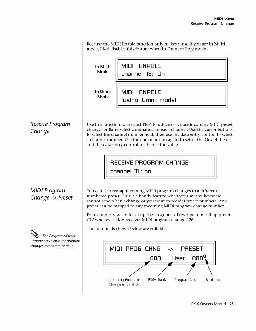
MIDI MenuReceive Program Change
Because the MIDI Enable function only makes sense if you are in Multi mode, PK-6 disables this feature when in Omni or Poly mode.
Receive Program Change
Use this function to instruct PK-6 to utilize or ignore incoming MIDI preset changes or Bank Select commands for each channel. Use the cursor buttons to select the channel number field, then use the data entry control to select a channel number. Use the cursor button again to select the On/Off field and the data entry control to change the value.
MIDI Program Change -> Preset
You can also remap incoming MIDI program changes to a different numbered preset. This is a handy feature when your master keyboard cannot send a bank change or you want to reorder preset numbers. Any preset can be mapped to any incoming MIDI program change number.
For example, you could set up the Program -> Preset map to call up preset #12 whenever PK-6 receives MIDI program change #26.
The four fields shown below are editable.
The Program->Preset Change only works for program changes received in Bank 0.
channel 16: OnMIDI ENABLEIn Multi
Mode
(using Omni mode)MIDI ENABLEIn Omni
Mode
RECEIVE PROGRAM CHANGEchannel 01 : on
MIDI PROG CHNG -> PRESET
000 User 0000
Incoming Program Change in Bank 0
ROM Bank Program No. Bank No.
PK-6 Owners Manual 95
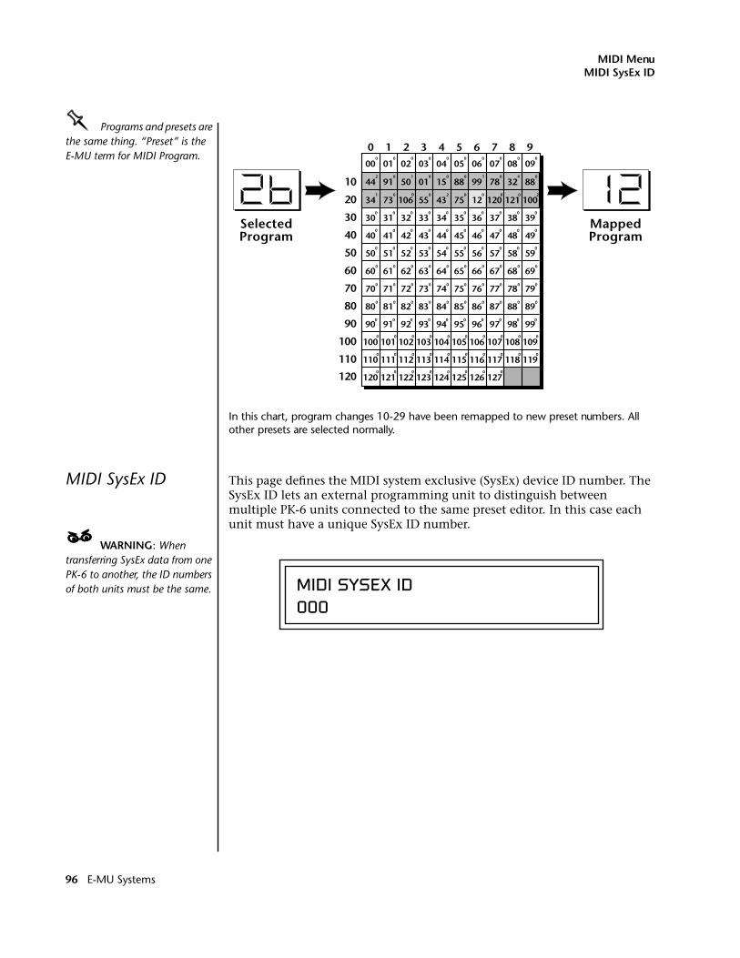
MIDI MenuMIDI SysEx ID
OOOO Programs and presets are the same thing. “Preset” is the E-MU term for MIDI Program.
In this chart, program changes 10-29 have been remapped to new preset numbers. All other presets are selected normally.
MIDI SysEx ID This page defines the MIDI system exclusive (SysEx) device ID number. The SysEx ID lets an external programming unit to distinguish between multiple PK-6 units connected to the same preset editor. In this case each unit must have a unique SysEx ID number.
____ WARNING: When transferring SysEx data from one PK-6 to another, the ID numbers of both units must be the same.
SelectedProgram
MappedProgram
0 1 2 3 4 5 6 7 8 9
10
20
30
40
50
60
70
80
90
100
110
120
00 01 02 03 04 05 06 07 08 09
30 31 32 33 34 35 36 37 38 39
40 41 42 43 44 45 46 47 48 49
50 51 52 53 54 55 56 57 58 59
60 61 62 63 64 65 66 67 68 69
70 71 72 73 74 75 76 77 78 79
80 81 82 83 84 85 86 87 88 89
90 91 92 93 94 95 96 97 98 99
100 101 102 103 104 105 106 107 108 109
110 111 112 113 114 115 116 117 118 119
120 121 122 123 124 125 126 127
44 91 50 01 15 88 99 78 32 88
34 73 106 55 43 75 120 121 10012
41
0 0 0 0 0 0 0 0 0 0
2 0 1 0 0 0 0 0
1 0 0 0 2 0 0 0 0 2
0 0 0 0 0 0 0 0 0 0
0 0 0 0 0 0 0 0 0 0
0 0 0 0 0 0 0 0 0 0
0 0 0 0 0 0 0 0 0 0
0 0 0 0 0 0 0 0 0 0
0 0 0 0 0 0 0 0 0 0
0 0 0 0 0 0 0 0 0 0
0 0 0 0 0 0 0 0 0 0
0 0 0 0 0 0 0 0 0 0
0 0 0 0 0 0 0 0
MIDI SYSEX ID000
96 E-MU Systems
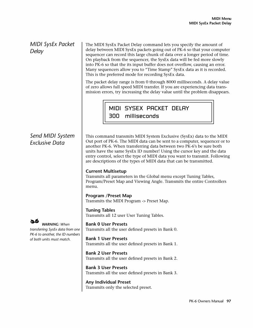
MIDI MenuMIDI SysEx Packet Delay
MIDI SysEx Packet Delay
The MIDI SysEx Packet Delay command lets you specify the amount of delay between MIDI SysEx packets going out of PK-6 so that your computer sequencer can record this large chunk of data over a longer period of time. On playback from the sequencer, the SysEx data will be fed more slowly into PK-6 so that the its input buffer does not overflow, causing an error. Many sequencers allow you to “Time Stamp” SysEx data as it is recorded. This is the preferred mode for recording SysEx data.
The packet delay range is from 0 through 8000 milliseconds. A delay value of zero allows full speed MIDI transfer. If you are experiencing data trans-mission errors, try increasing the delay value until the problem disappears.
Send MIDI System Exclusive Data
This command transmits MIDI System Exclusive (SysEx) data to the MIDI Out port of PK-6. The MIDI data can be sent to a computer, sequencer or to another PK-6. When transferring data between two PK-6’s be sure both units have the same SysEx ID number! Using the cursor key and the data entry control, select the type of MIDI data you want to transmit. Following are descriptions of the types of MIDI data that can be transmitted.
Current MultisetupTransmits all parameters in the Global menu except Tuning Tables, Program/Preset Map and Viewing Angle. Transmits the entire Controllers menu.
Program /Preset MapTransmits the MIDI Program -> Preset Map.
Tuning TablesTransmits all 12 user User Tuning Tables.
____ WARNING: When transferring SysEx data from one PK-6 to another, the ID numbers of both units must match.
Bank 0 User PresetsTransmits all the user defined presets in Bank 0.
Bank 1 User PresetsTransmits all the user defined presets in Bank 1.
Bank 2 User PresetsTransmits all the user defined presets in Bank 2.
Bank 3 User PresetsTransmits all the user defined presets in Bank 3.
Any Individual PresetTransmits only the selected preset.
MIDI SYSEX PACKET DELAY 300 milliseconds
PK-6 Owners Manual 97
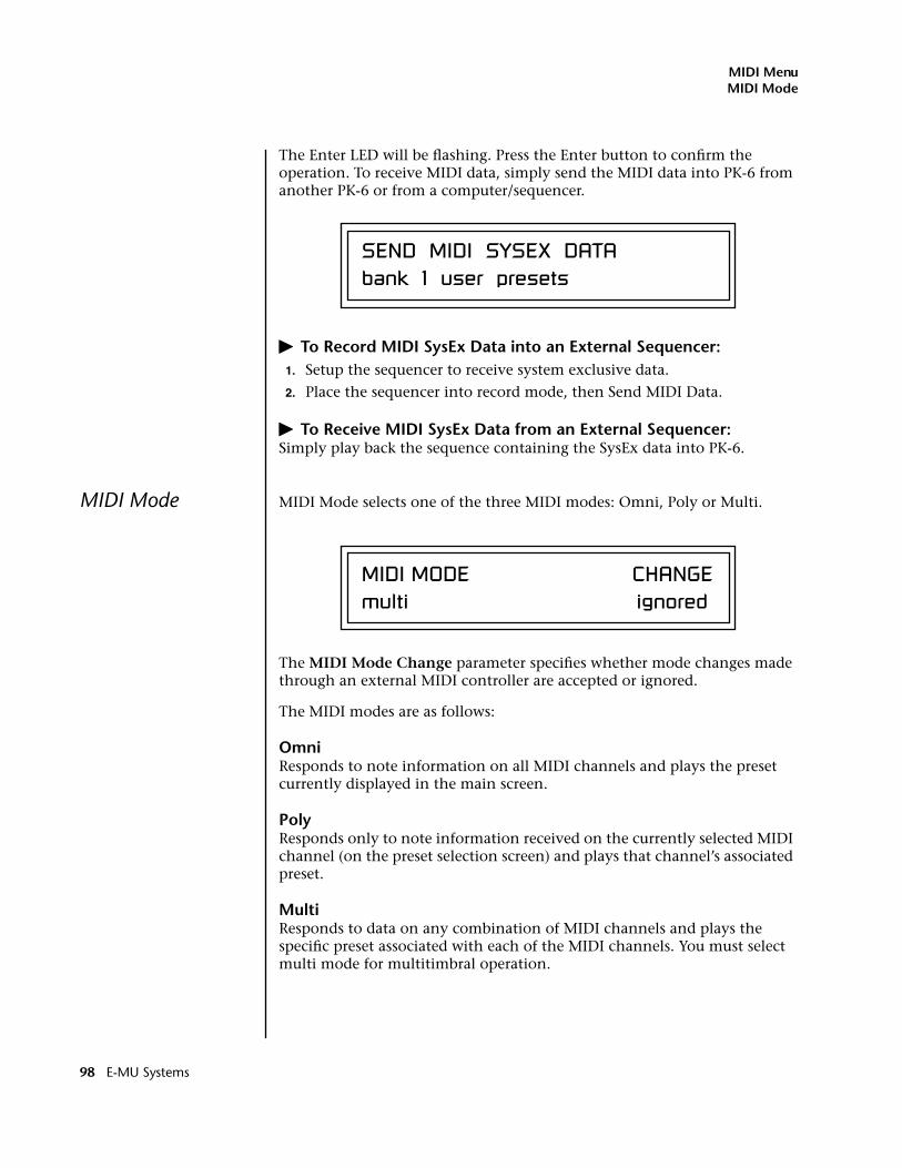
MIDI MenuMIDI Mode
The Enter LED will be flashing. Press the Enter button to confirm the operation. To receive MIDI data, simply send the MIDI data into PK-6 from another PK-6 or from a computer/sequencer.
� To Record MIDI SysEx Data into an External Sequencer:1. Setup the sequencer to receive system exclusive data.
2. Place the sequencer into record mode, then Send MIDI Data.
� To Receive MIDI SysEx Data from an External Sequencer:Simply play back the sequence containing the SysEx data into PK-6.
MIDI Mode MIDI Mode selects one of the three MIDI modes: Omni, Poly or Multi.
The MIDI Mode Change parameter specifies whether mode changes made through an external MIDI controller are accepted or ignored.
The MIDI modes are as follows:
OmniResponds to note information on all MIDI channels and plays the preset currently displayed in the main screen.
PolyResponds only to note information received on the currently selected MIDI channel (on the preset selection screen) and plays that channel’s associated preset.
MultiResponds to data on any combination of MIDI channels and plays the specific preset associated with each of the MIDI channels. You must select multi mode for multitimbral operation.
SEND MIDI SYSEX DATA bank 1 user presets
MIDI MODE CHANGEmulti ignored
98 E-MU Systems
Programming Basics
This chapter explains how PK-6 sounds are constructed and contains important background information on how to create your own custom presets.
Your initial involvement with PK-6 will most likely be using the existing presets and selecting MIDI channels. While the factory presets are very good, there are some things you will probably want to change eventually, perhaps the LFO speed, the filter frequency or the attack time. You may also want to make your own custom presets using complex modulation routings. This module will do far more than you ever imagined and there are whole new classes of sound just waiting to be discovered.
Each preset can consist of up to four instrument layers. Each of the four layers can be placed anywhere on the keyboard and can be crossfaded or switched according to key position, velocity, or by using a real-time control such as a wheel, slider, pedal, LFO or envelope generator. A preset can also be “linked” with up to 2 more presets creating additional layering or splits.
PK-6 has an extensive modulation implementation using two multi-wave LFO’s (Low Frequency Oscillators), three multi-stage envelope generators and the ability to respond to multiple MIDI controllers. You can simulta-neously route any combination of these control sources to multiple desti-nations.
There are 512 user locations (USER Banks 0-3) available to store your own creations or edited factory presets. It’s easy and fun to edit or create your own unique presets.
PK-6 Owners Manual 99
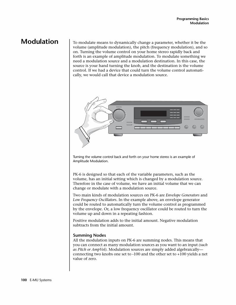
Programming BasicsModulation
Modulation To modulate means to dynamically change a parameter, whether it be the volume (amplitude modulation), the pitch (frequency modulation), and so on. Turning the volume control on your home stereo rapidly back and forth is an example of amplitude modulation. To modulate something we need a modulation source and a modulation destination. In this case, the source is your hand turning the knob, and the destination is the volume control. If we had a device that could turn the volume control automati-cally, we would call that device a modulation source.
Turning the volume control back and forth on your home stereo is an example of Amplitude Modulation.
PK-6 is designed so that each of the variable parameters, such as the volume, has an initial setting which is changed by a modulation source. Therefore in the case of volume, we have an initial volume that we can change or modulate with a modulation source.
Two main kinds of modulation sources on PK-6 are Envelope Generators and Low Frequency Oscillators. In the example above, an envelope generator could be routed to automatically turn the volume control as programmed by the envelope. Or, a low frequency oscillator could be routed to turn the volume up and down in a repeating fashion.
Positive modulation adds to the initial amount. Negative modulation subtracts from the initial amount.
Summing NodesAll the modulation inputs on PK-6 are summing nodes. This means that you can connect as many modulation sources as you want to an input (such as Pitch or AmpVol). Modulation sources are simply added algebraically— connecting two knobs one set to -100 and the other set to +100 yields a net value of zero.
Volume
100 E-MU Systems
Programming BasicsModulation Sources
Modulation Sources
Modulation sources include Envelope Generators, Performance Controllers and Low Frequency Oscillators. In the previous example, an envelope generator was routed to automatically turn the volume control as programmed by the envelope, or, a low frequency oscillator could be routed to turn the volume control up and down in a repeating fashion. The following is a list of the modulation sources used in PK-6.
Keyboard KeyWhich key is pressed.
Key VelocityHow fast the key is pressed.
Release VelocityHow fast the key is released.
GateHigh if the key is pressed, low when the key is released.
OOOO Tip: Try routing Key Glide to Filter Frequency if you want the filter to smoothly follow pitch in solo mode. Routing Key Glide to Pan creates another interesting effect.
Key GlideA smoothly changing control source based on the Glide Rate and the interval between the last two notes played.
Pitch and Mod ControllersSynthesizer pitch bend and modulation controllers.
Keyboard Pressure (mono aftertouch)Key Pressure applied after the keyboard key is initially pressed.
PedalA continuously variable pedal controller.
Miscellaneous Controllers A -PAny type of MIDI continuous controller data.
Low Frequency Oscillators (2 per layer)Generate repeating waves.
Envelope Generators (3 per layer)Generate a programmable “contour” which changes over time when a key is pressed.
Noise & Random GeneratorsGenerate spectrums of noise and random signals.
Footswitches Change a parameter when the switch is pressed.
Clock Divisor The master tempo clock can be divided and used as a modulation source.
PK-6 Owners Manual 101
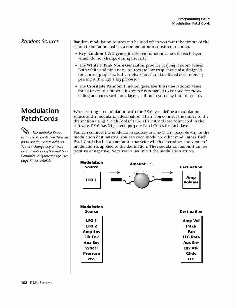
Programming BasicsModulation PatchCords
Random Sources Random modulation sources can be used when you want the timbre of the sound to be “animated” in a random or non-consistent manner.
• Key Random 1 & 2 generate different random values for each layer which do not change during the note.
• The White & Pink Noise Generators produce varying random values. Both white and pink noise sources are low frequency noise designed for control purposes. Either noise source can be filtered even more by passing it through a lag processor.
• The Crossfade Random function generates the same random value for all layers in a preset. This source is designed to be used for cross-fading and cross-switching layers, although you may find other uses.
Modulation PatchCords
When setting up modulation with the PK-6, you define a modulation source and a modulation destination. Then, you connect the source to the destination using “PatchCords.” PK-6’s PatchCords are connected in the software. PK-6 has 24 general purpose PatchCords for each layer.
The controller Knobs assignments printed on the front panel are the system defaults. You can change any of these assignments using the Real-time Controller Assignment page (see page 79 for details).
You can connect the modulation sources in almost any possible way to the modulation destinations. You can even modulate other modulators. Each PatchCord also has an amount parameter which determines “how much” modulation is applied to the destination. The modulation amount can be positive or negative. Negative values invert the modulation source.
ModulationSource
LFO 1
DestinationAmount +/-
AmpVolume
ModulationSource
LFO 1LFO 2
Amp EnvFilt EnvAux EnvWheel
Pressureetc.
Amp VolPitchPan
LFO RateAux EnvEnv Atk
Glideetc.
Destination
- +
102 E-MU Systems
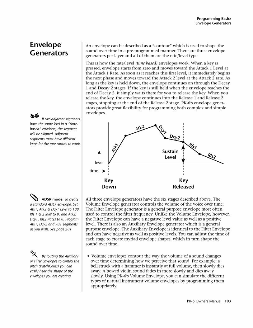
Programming BasicsEnvelope Generators
Envelope Generators
An envelope can be described as a “contour” which is used to shape the sound over time in a pre-programmed manner. There are three envelope generators per layer and all of them are the rate/level type.
This is how the rate/level (time based) envelopes work: When a key is pressed, envelope starts from zero and moves toward the Attack 1 Level at the Attack 1 Rate. As soon as it reaches this first level, it immediately begins the next phase and moves toward the Attack 2 level at the Attack 2 rate. As long as the key is held down, the envelope continues on through the Decay 1 and Decay 2 stages. If the key is still held when the envelope reaches the end of Decay 2, it simply waits there for you to release the key. When you release the key, the envelope continues into the Release 1 and Release 2 stages, stopping at the end of the Release 2 stage. PK-6’s envelope gener-ators provide great flexibility for programming both complex and simple envelopes.
____ If two adjacent segments have the same level in a “time-based” envelope, the segment will be skipped. Adjacent segments must have different levels for the rate control to work.
ADSR mode: To create a standard ADSR envelope: Set Atk1, Atk2 & Dcy1 Level to 100, Rls 1 & 2 level to 0, and Atk2, Dcy1, Rls2 Rates to 0. Program Atk1, Dcy2 and Rls1 segments as you wish. See page 201.
All three envelope generators have the six stages described above. The Volume Envelope generator controls the volume of the voice over time. The Filter Envelope generator is a general purpose envelope most often used to control the filter frequency. Unlike the Volume Envelope, however, the Filter Envelope can have a negative level value as well as a positive level. There is also an Auxiliary Envelope generator which is a general purpose envelope. The Auxiliary Envelope is identical to the Filter Envelope and can have negative as well as positive levels. You can adjust the time of each stage to create myriad envelope shapes, which in turn shape the sound over time.
OOOO By routing the Auxiliary or Filter Envelopes to control the pitch (PatchCords) you can easily hear the shape of the envelopes you are creating.
• Volume envelopes contour the way the volume of a sound changes over time determining how we perceive that sound. For example, a bell struck with a hammer is instantly at full volume, then slowly dies away. A bowed violin sound fades in more slowly and dies away slowly. Using PK-6’s Volume Envelope, you can simulate the different types of natural instrument volume envelopes by programming them appropriately.
Atk1
Atk2 Dcy1
Dcy2Rls1
Rls2
KeyDown
KeyReleased
SustainLevel
time
level
PK-6 Owners Manual 103
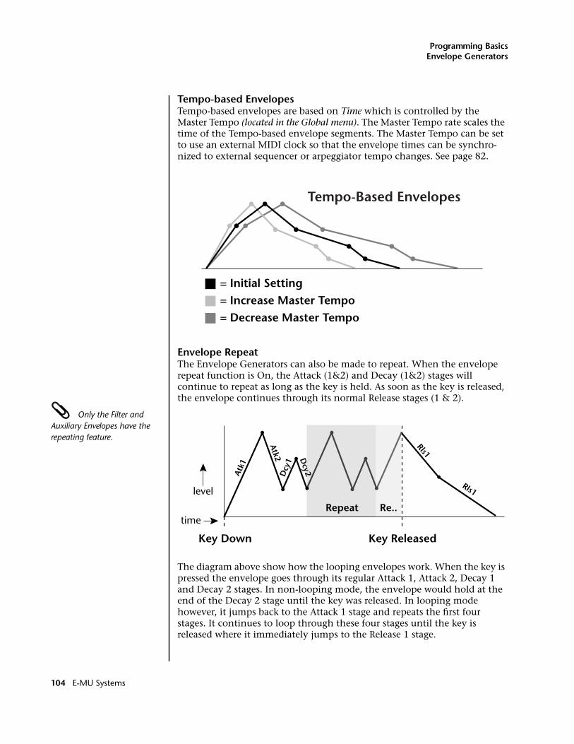
Programming BasicsEnvelope Generators
Tempo-based EnvelopesTempo-based envelopes are based on Time which is controlled by the Master Tempo (located in the Global menu). The Master Tempo rate scales the time of the Tempo-based envelope segments. The Master Tempo can be set to use an external MIDI clock so that the envelope times can be synchro-nized to external sequencer or arpeggiator tempo changes. See page 82.
Envelope RepeatThe Envelope Generators can also be made to repeat. When the envelope repeat function is On, the Attack (1&2) and Decay (1&2) stages will continue to repeat as long as the key is held. As soon as the key is released, the envelope continues through its normal Release stages (1 & 2).
Only the Filter and Auxiliary Envelopes have the repeating feature.
The diagram above show how the looping envelopes work. When the key is pressed the envelope goes through its regular Attack 1, Attack 2, Decay 1 and Decay 2 stages. In non-looping mode, the envelope would hold at the end of the Decay 2 stage until the key was released. In looping mode however, it jumps back to the Attack 1 stage and repeats the first four stages. It continues to loop through these four stages until the key is released where it immediately jumps to the Release 1 stage.
= Initial Setting= Increase Master Tempo= Decrease Master Tempo
Tempo-Based Envelopes
Atk
1
Atk2 D
cy2Dcy
1
Rls1
Rls1
Key Down Key Released
time
level
Repeat Re..
104 E-MU Systems
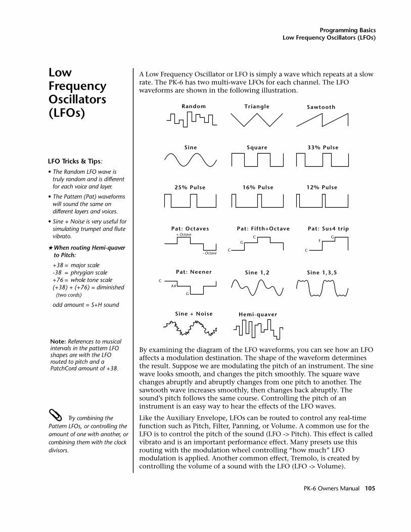
Programming BasicsLow Frequency Oscillators (LFOs)
Low Frequency Oscillators (LFOs)
A Low Frequency Oscillator or LFO is simply a wave which repeats at a slow rate. The PK-6 has two multi-wave LFOs for each channel. The LFO waveforms are shown in the following illustration.
By examining the diagram of the LFO waveforms, you can see how an LFO affects a modulation destination. The shape of the waveform determines the result. Suppose we are modulating the pitch of an instrument. The sine wave looks smooth, and changes the pitch smoothly. The square wave changes abruptly and abruptly changes from one pitch to another. The sawtooth wave increases smoothly, then changes back abruptly. The sound’s pitch follows the same course. Controlling the pitch of an instrument is an easy way to hear the effects of the LFO waves.
Try combining the Pattern LFOs, or controlling the amount of one with another, or combining them with the clock divisors.
Like the Auxiliary Envelope, LFOs can be routed to control any real-time function such as Pitch, Filter, Panning, or Volume. A common use for the LFO is to control the pitch of the sound (LFO -> Pitch). This effect is called vibrato and is an important performance effect. Many presets use this routing with the modulation wheel controlling “how much” LFO modulation is applied. Another common effect, Tremolo, is created by controlling the volume of a sound with the LFO (LFO -> Volume).
Triangle
Square
Sine 1,2 Sine 1,3,5
Sine
Sawtooth
25% Pulse
33% Pulse
12% Pulse16% Pulse
Random
Pat: Fifth+Octave
C
CG
Pat: Octaves+ Octave
- OctaveC
FG
Pat: Sus4 trip
C
G
A#
Pat: Neener
Hemi-quaver Sine + Noise
LFO Tricks & Tips:
• The Random LFO wave is truly random and is different for each voice and layer.
• The Pattern (Pat) waveforms will sound the same on different layers and voices.
• Sine + Noise is very useful for simulating trumpet and flutevibrato.
�When routing Hemi-quaver to Pitch:
+38 = major scale-38 = phrygian scale+76 = whole tone scale(+38) + (+76) = diminished (two cords)
odd amount = S+H sound
Note: References to musical intervals in the pattern LFO shapes are with the LFO routed to pitch and a PatchCord amount of +38.
PK-6 Owners Manual 105
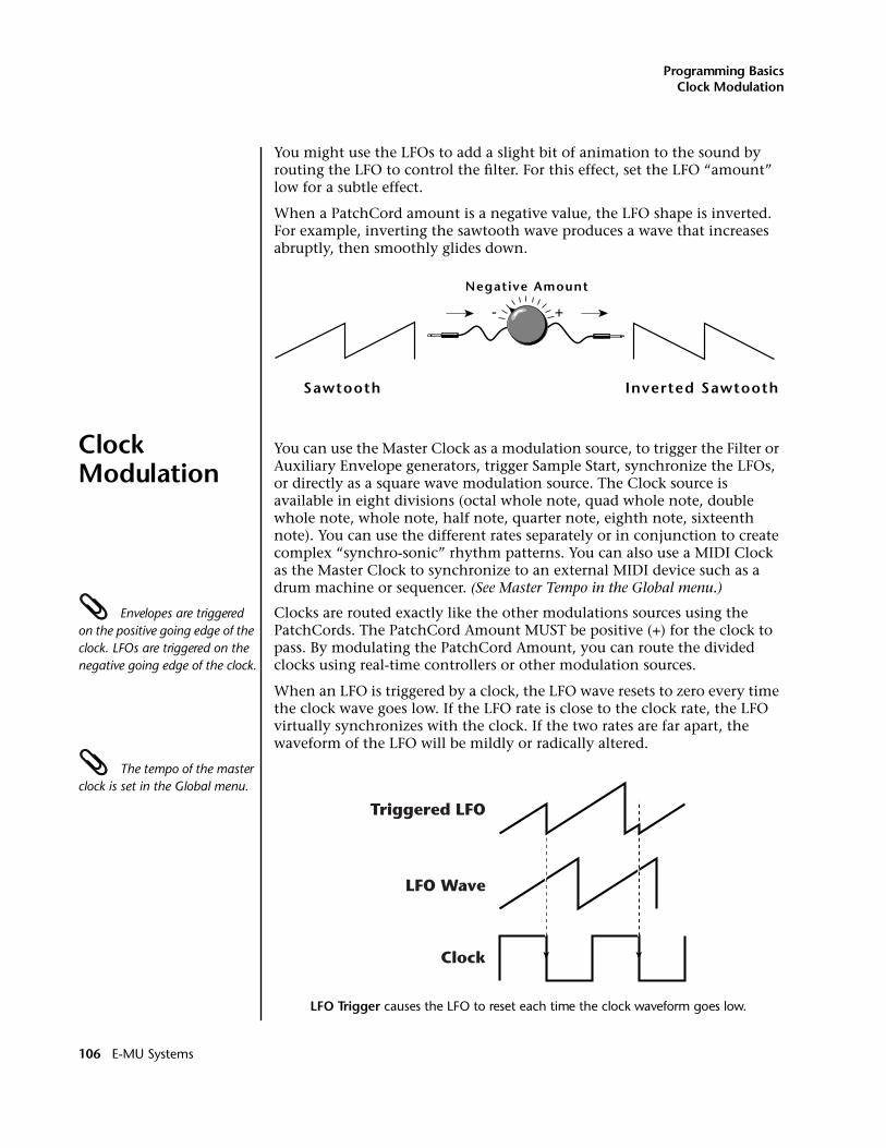
Programming BasicsClock Modulation
You might use the LFOs to add a slight bit of animation to the sound by routing the LFO to control the filter. For this effect, set the LFO “amount” low for a subtle effect.
When a PatchCord amount is a negative value, the LFO shape is inverted. For example, inverting the sawtooth wave produces a wave that increases abruptly, then smoothly glides down.
Clock Modulation
You can use the Master Clock as a modulation source, to trigger the Filter or Auxiliary Envelope generators, trigger Sample Start, synchronize the LFOs, or directly as a square wave modulation source. The Clock source is available in eight divisions (octal whole note, quad whole note, double whole note, whole note, half note, quarter note, eighth note, sixteenth note). You can use the different rates separately or in conjunction to create complex “synchro-sonic” rhythm patterns. You can also use a MIDI Clock as the Master Clock to synchronize to an external MIDI device such as a drum machine or sequencer. (See Master Tempo in the Global menu.)
Envelopes are triggered on the positive going edge of the clock. LFOs are triggered on the negative going edge of the clock.
Clocks are routed exactly like the other modulations sources using the PatchCords. The PatchCord Amount MUST be positive (+) for the clock to pass. By modulating the PatchCord Amount, you can route the divided clocks using real-time controllers or other modulation sources.
When an LFO is triggered by a clock, the LFO wave resets to zero every time the clock wave goes low. If the LFO rate is close to the clock rate, the LFO virtually synchronizes with the clock. If the two rates are far apart, the waveform of the LFO will be mildly or radically altered.
The tempo of the master clock is set in the Global menu.
LFO Trigger causes the LFO to reset each time the clock waveform goes low.
Inverted Sawtooth
Negative Amount
+-
Sawtooth
Clock
LFO Wave
Triggered LFO
106 E-MU Systems
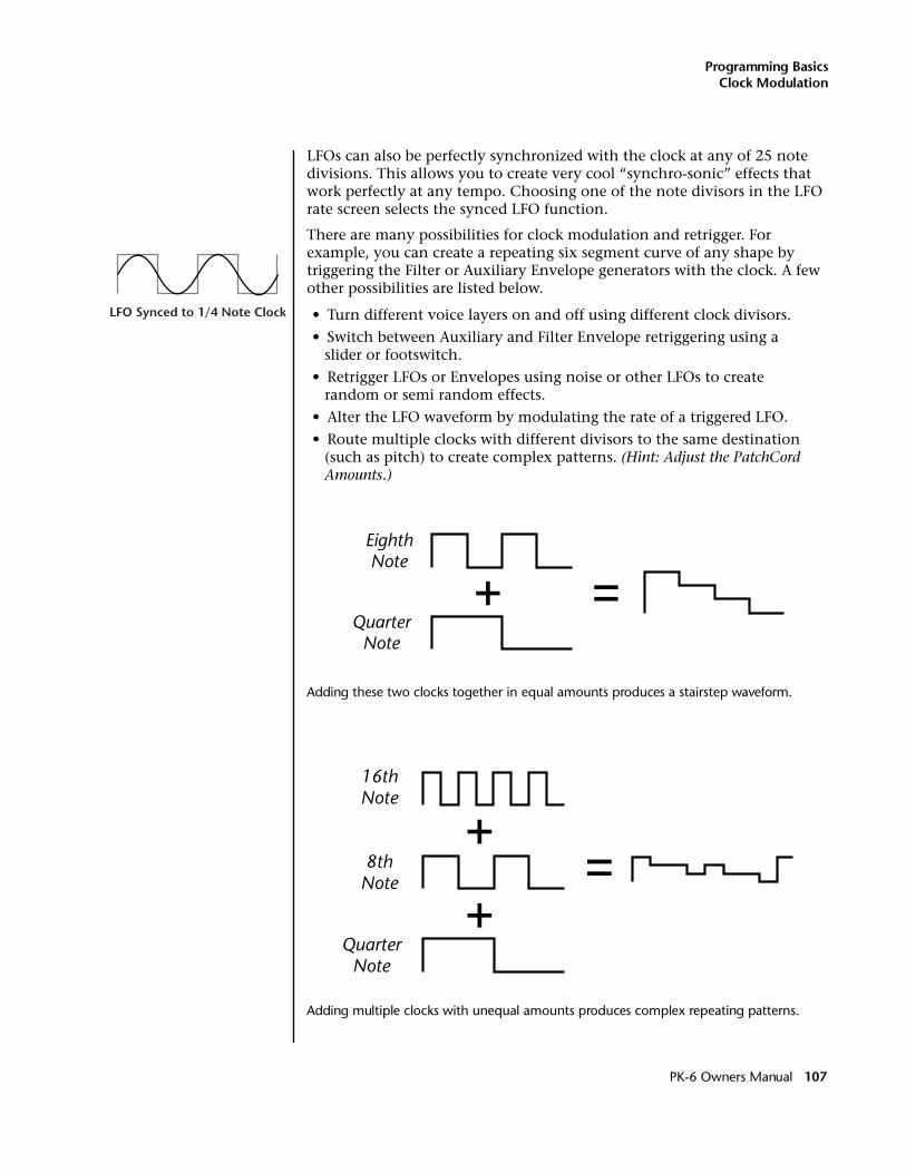
Programming BasicsClock Modulation
LFOs can also be perfectly synchronized with the clock at any of 25 note divisions. This allows you to create very cool “synchro-sonic” effects that work perfectly at any tempo. Choosing one of the note divisors in the LFO rate screen selects the synced LFO function.
There are many possibilities for clock modulation and retrigger. For example, you can create a repeating six segment curve of any shape by triggering the Filter or Auxiliary Envelope generators with the clock. A few other possibilities are listed below.
• Turn different voice layers on and off using different clock divisors.
• Switch between Auxiliary and Filter Envelope retriggering using a slider or footswitch.
• Retrigger LFOs or Envelopes using noise or other LFOs to create random or semi random effects.
• Alter the LFO waveform by modulating the rate of a triggered LFO.
• Route multiple clocks with different divisors to the same destination (such as pitch) to create complex patterns. (Hint: Adjust the PatchCord Amounts.)
Adding these two clocks together in equal amounts produces a stairstep waveform.
Adding multiple clocks with unequal amounts produces complex repeating patterns.
LFO Synced to 1/4 Note Clock
QuarterNote
EighthNote
QuarterNote
8thNote
16thNote
PK-6 Owners Manual 107
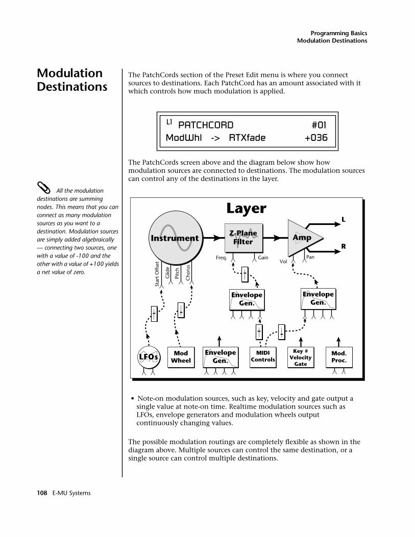
Programming BasicsModulation Destinations
Modulation Destinations
The PatchCords section of the Preset Edit menu is where you connect sources to destinations. Each PatchCord has an amount associated with it which controls how much modulation is applied.
The PatchCords screen above and the diagram below show how modulation sources are connected to destinations. The modulation sources can control any of the destinations in the layer.
All the modulation destinations are summing nodes. This means that you can connect as many modulation sources as you want to a destination. Modulation sources are simply added algebraically — connecting two sources, one with a value of -100 and the other with a value of +100 yields a net value of zero.
• Note-on modulation sources, such as key, velocity and gate output a single value at note-on time. Realtime modulation sources such as LFOs, envelope generators and modulation wheels output continuously changing values.
The possible modulation routings are completely flexible as shown in the diagram above. Multiple sources can control the same destination, or a single source can control multiple destinations.
L1 PATCHCORD #01ModWhl -> RTXfade +036
Instrument Amp
L
R
EnvelopeGen.
Freq. GainVol
Star
t O
ffset
Pitc
h
Glid
e
Cho
rus
Pan
Layer
Z-PlaneFilter
EnvelopeGen.
EnvelopeGen.LFOs Mod
WheelMIDI
ControlsMod.Proc.
Key #Velocity
Gate
108 E-MU Systems
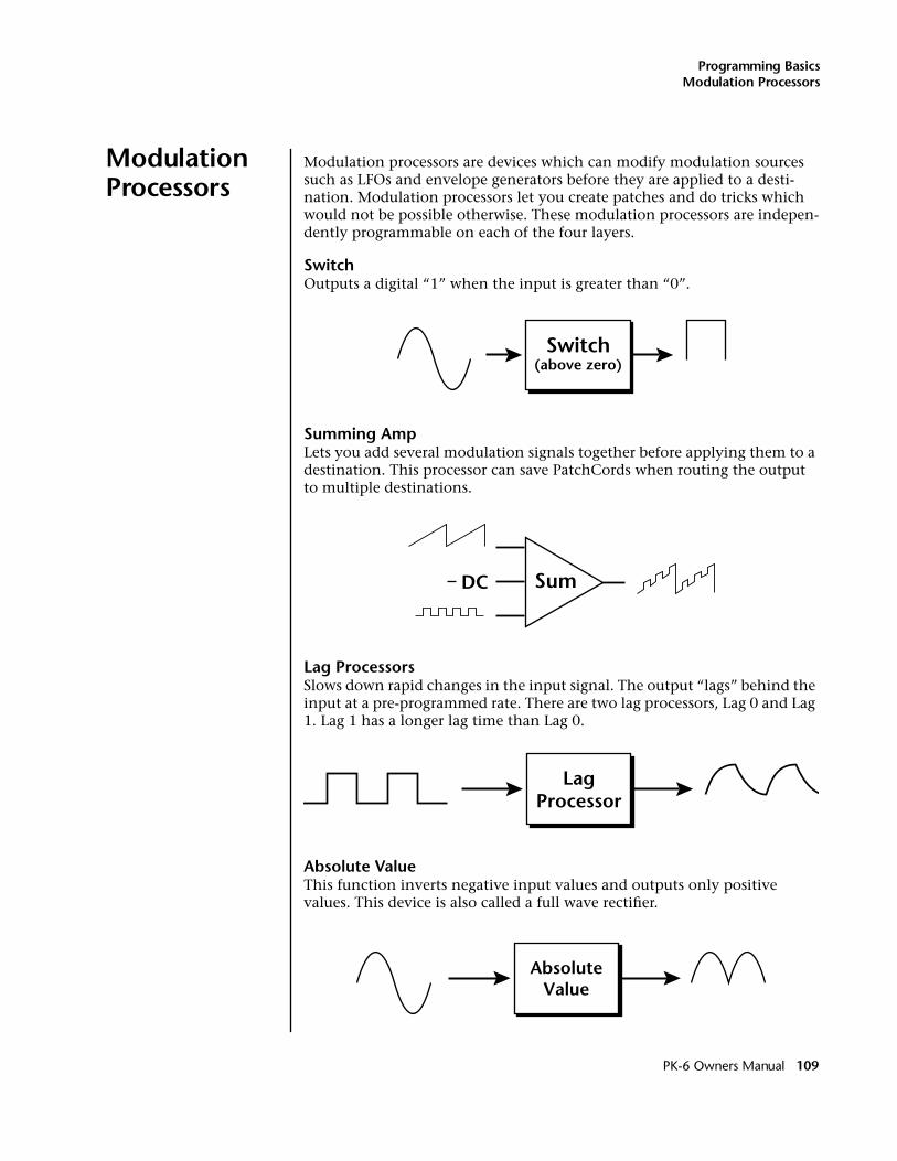
Programming BasicsModulation Processors
Modulation Processors
Modulation processors are devices which can modify modulation sources such as LFOs and envelope generators before they are applied to a desti-nation. Modulation processors let you create patches and do tricks which would not be possible otherwise. These modulation processors are indepen-dently programmable on each of the four layers.
SwitchOutputs a digital “1” when the input is greater than “0”.
Summing AmpLets you add several modulation signals together before applying them to a destination. This processor can save PatchCords when routing the output to multiple destinations.
Lag ProcessorsSlows down rapid changes in the input signal. The output “lags” behind the input at a pre-programmed rate. There are two lag processors, Lag 0 and Lag 1. Lag 1 has a longer lag time than Lag 0.
Absolute ValueThis function inverts negative input values and outputs only positive values. This device is also called a full wave rectifier.
Switch(above zero)
SumDC
LagProcessor
AbsoluteValue
PK-6 Owners Manual 109
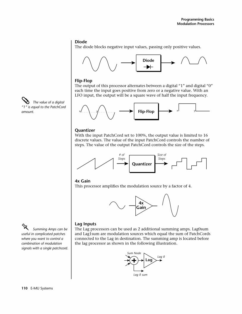
Programming BasicsModulation Processors
DiodeThe diode blocks negative input values, passing only positive values.
Flip-FlopThe output of this processor alternates between a digital “1” and digital “0” each time the input goes positive from zero or a negative value. With an LFO input, the output will be a square wave of half the input frequency.
The value of a digital “1” is equal to the PatchCord amount.
QuantizerWith the input PatchCord set to 100%, the output value is limited to 16 discrete values. The value of the input PatchCord controls the number of steps. The value of the output PatchCord controls the size of the steps.
4x GainThis processor amplifies the modulation source by a factor of 4.
Lag InputsOOOO Summing Amps can be useful in complicated patches where you want to control a combination of modulation signals with a single patchcord.
The Lag processors can be used as 2 additional summing amps. Lag0sum and Lag1sum are modulation sources which equal the sum of PatchCords connected to the Lag in destination. The summing amp is located before the lag processor as shown in the following illustration.
Diode
Flip-Flopx y x y
Quantizer
# ofSteps
Size ofSteps
4xGain
Lag
Sum Node
Lag 0 sum
Lag 0
110 E-MU Systems
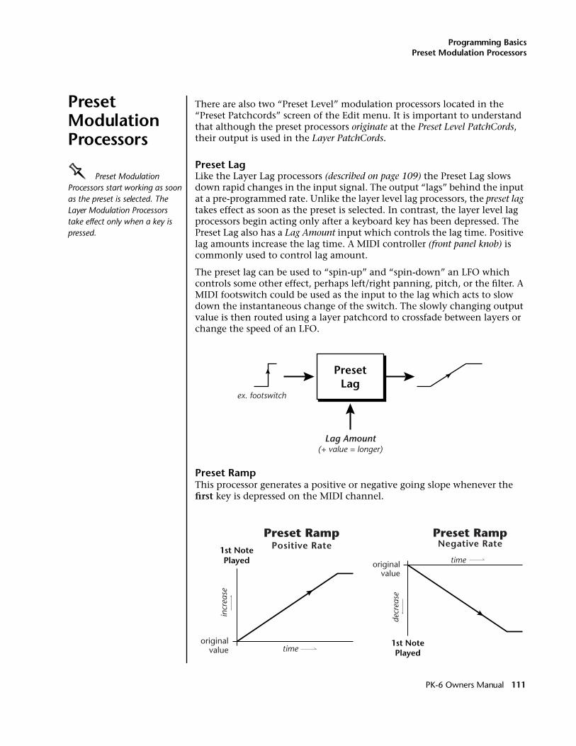
Programming BasicsPreset Modulation Processors
Preset Modulation Processors
There are also two “Preset Level” modulation processors located in the “Preset Patchcords” screen of the Edit menu. It is important to understand that although the preset processors originate at the Preset Level PatchCords, their output is used in the Layer PatchCords.
Preset LagOOOO Preset Modulation Processors start working as soon as the preset is selected. The Layer Modulation Processors take effect only when a key is pressed.
Like the Layer Lag processors (described on page 109) the Preset Lag slows down rapid changes in the input signal. The output “lags” behind the input at a pre-programmed rate. Unlike the layer level lag processors, the preset lag takes effect as soon as the preset is selected. In contrast, the layer level lag processors begin acting only after a keyboard key has been depressed. The Preset Lag also has a Lag Amount input which controls the lag time. Positive lag amounts increase the lag time. A MIDI controller (front panel knob) is commonly used to control lag amount.
The preset lag can be used to “spin-up” and “spin-down” an LFO which controls some other effect, perhaps left/right panning, pitch, or the filter. A MIDI footswitch could be used as the input to the lag which acts to slow down the instantaneous change of the switch. The slowly changing output value is then routed using a layer patchcord to crossfade between layers or change the speed of an LFO.
Preset RampThis processor generates a positive or negative going slope whenever the first key is depressed on the MIDI channel.
PresetLag
Lag Amount(+ value = longer)
ex. footswitch
Preset Ramp1st NotePlayed
time
incr
ease
originalvalue
Positive RatePreset Ramp
decr
ease
originalvalue
1st NotePlayed
time
Negative Rate
PK-6 Owners Manual 111
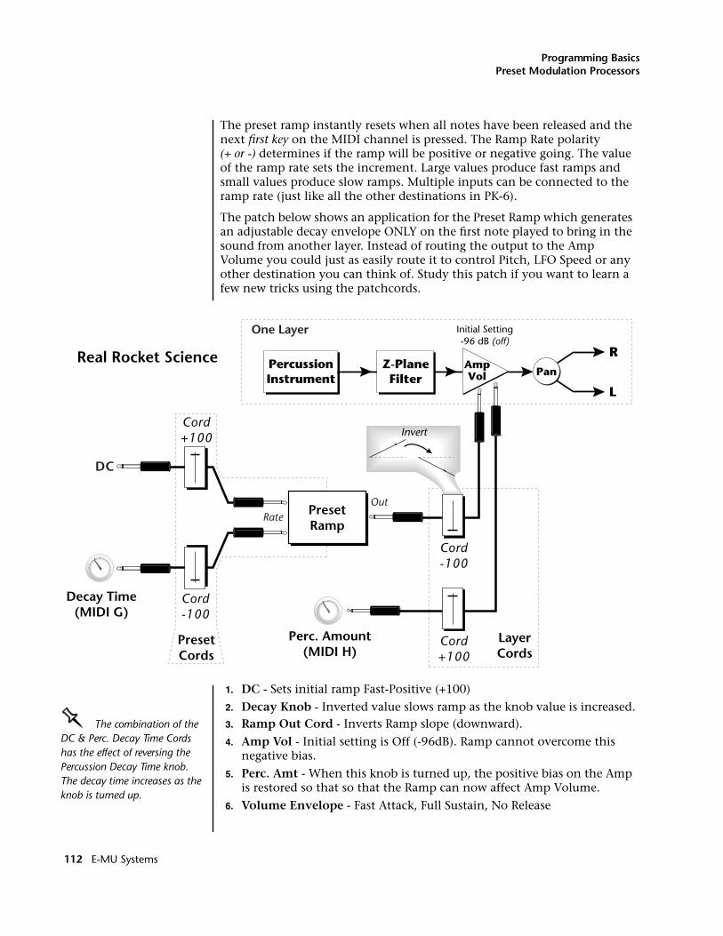
Programming BasicsPreset Modulation Processors
The preset ramp instantly resets when all notes have been released and the next first key on the MIDI channel is pressed. The Ramp Rate polarity (+ or -) determines if the ramp will be positive or negative going. The value of the ramp rate sets the increment. Large values produce fast ramps and small values produce slow ramps. Multiple inputs can be connected to the ramp rate (just like all the other destinations in PK-6).
The patch below shows an application for the Preset Ramp which generates an adjustable decay envelope ONLY on the first note played to bring in the sound from another layer. Instead of routing the output to the Amp Volume you could just as easily route it to control Pitch, LFO Speed or any other destination you can think of. Study this patch if you want to learn a few new tricks using the patchcords.
1. DC - Sets initial ramp Fast-Positive (+100)
2. Decay Knob - Inverted value slows ramp as the knob value is increased.OOOO The combination of the DC & Perc. Decay Time Cords has the effect of reversing the Percussion Decay Time knob. The decay time increases as the knob is turned up.
3. Ramp Out Cord - Inverts Ramp slope (downward).
4. Amp Vol - Initial setting is Off (-96dB). Ramp cannot overcome this negative bias.
5. Perc. Amt - When this knob is turned up, the positive bias on the Amp is restored so that so that the Ramp can now affect Amp Volume.
6. Volume Envelope - Fast Attack, Full Sustain, No Release
Invert
PresetRamp
OutRate
Cord-100
Cord+100
DC
Cord-100
R
L
PanPercussionInstrument
AmpVol
Z-PlaneFilter
Initial Setting-96 dB (off)
Perc. Amount(MIDI H)
Decay Time(MIDI G)
Cord+100
LayerCords
PresetCords
One Layer
Real Rocket Science
112 E-MU Systems
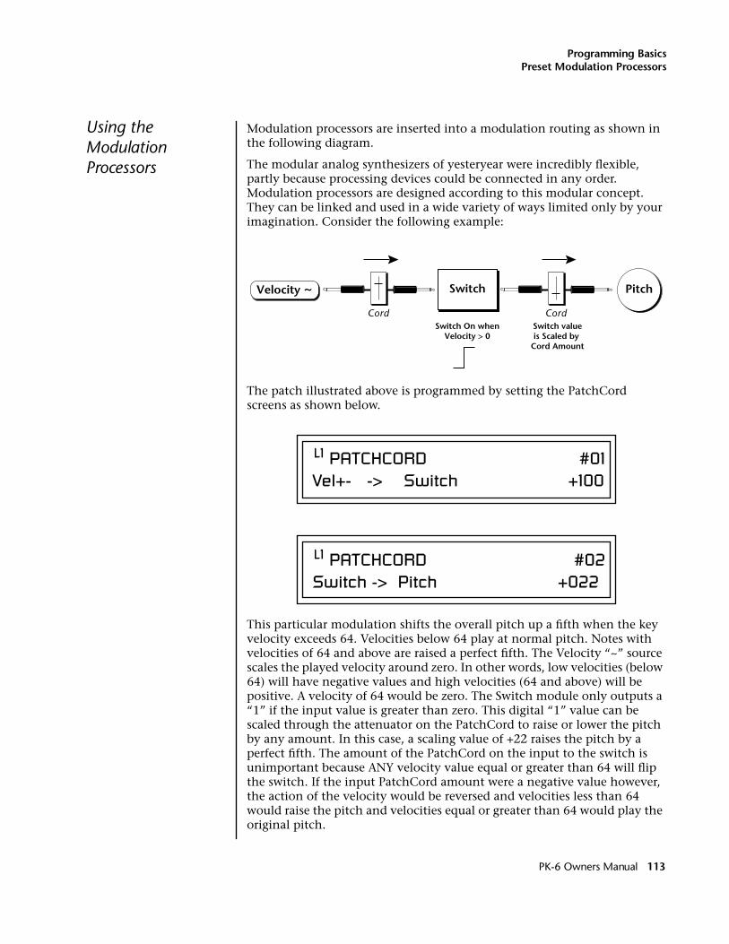
Programming BasicsPreset Modulation Processors
Using the Modulation Processors
Modulation processors are inserted into a modulation routing as shown in the following diagram.
The modular analog synthesizers of yesteryear were incredibly flexible, partly because processing devices could be connected in any order. Modulation processors are designed according to this modular concept. They can be linked and used in a wide variety of ways limited only by your imagination. Consider the following example:
The patch illustrated above is programmed by setting the PatchCord screens as shown below.
This particular modulation shifts the overall pitch up a fifth when the key velocity exceeds 64. Velocities below 64 play at normal pitch. Notes with velocities of 64 and above are raised a perfect fifth. The Velocity “~” source scales the played velocity around zero. In other words, low velocities (below 64) will have negative values and high velocities (64 and above) will be positive. A velocity of 64 would be zero. The Switch module only outputs a “1” if the input value is greater than zero. This digital “1” value can be scaled through the attenuator on the PatchCord to raise or lower the pitch by any amount. In this case, a scaling value of +22 raises the pitch by a perfect fifth. The amount of the PatchCord on the input to the switch is unimportant because ANY velocity value equal or greater than 64 will flip the switch. If the input PatchCord amount were a negative value however, the action of the velocity would be reversed and velocities less than 64 would raise the pitch and velocities equal or greater than 64 would play the original pitch.
SwitchVelocity ~ Pitch
Cord CordSwitch On when
Velocity > 0Switch valueis Scaled by
Cord Amount
L1 PATCHCORD #01Vel+- -> Switch +100
L1 PATCHCORD #02Switch -> Pitch +022
PK-6 Owners Manual 113
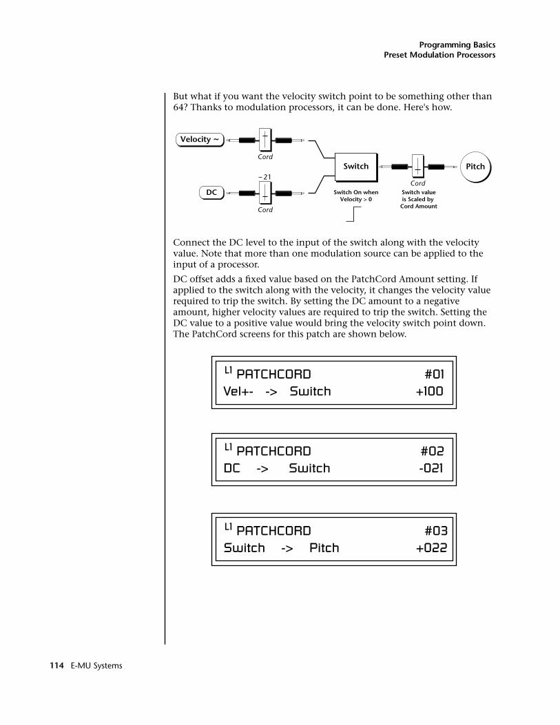
Programming BasicsPreset Modulation Processors
But what if you want the velocity switch point to be something other than 64? Thanks to modulation processors, it can be done. Here's how.
Connect the DC level to the input of the switch along with the velocity value. Note that more than one modulation source can be applied to the input of a processor.
DC offset adds a fixed value based on the PatchCord Amount setting. If applied to the switch along with the velocity, it changes the velocity value required to trip the switch. By setting the DC amount to a negative amount, higher velocity values are required to trip the switch. Setting the DC value to a positive value would bring the velocity switch point down. The PatchCord screens for this patch are shown below.
Switch
Velocity ~
PitchCord
Cord
21Cord
Switch On whenVelocity > 0
Switch valueis Scaled by
Cord Amount
DC
L1 PATCHCORD #01Vel+- -> Switch +100
L1 PATCHCORD #02DC -> Switch -021
L1 PATCHCORD #03Switch -> Pitch +022
114 E-MU Systems
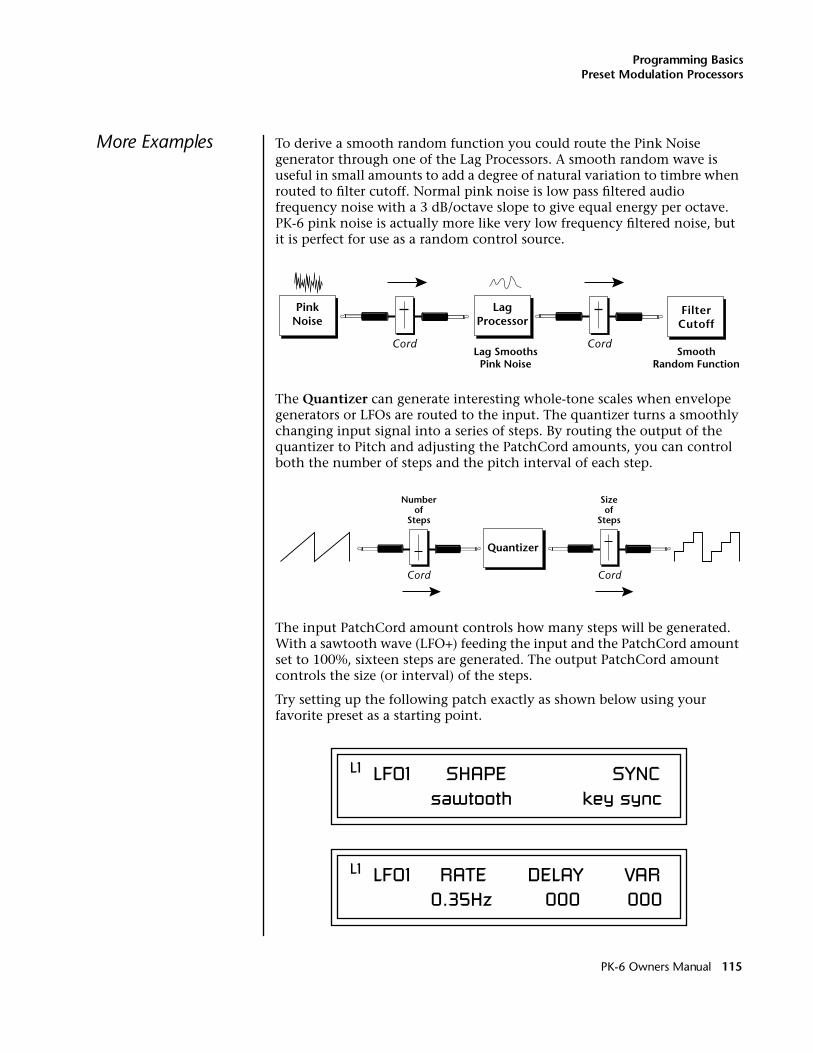
Programming BasicsPreset Modulation Processors
More Examples To derive a smooth random function you could route the Pink Noise generator through one of the Lag Processors. A smooth random wave is useful in small amounts to add a degree of natural variation to timbre when routed to filter cutoff. Normal pink noise is low pass filtered audio frequency noise with a 3 dB/octave slope to give equal energy per octave. PK-6 pink noise is actually more like very low frequency filtered noise, but it is perfect for use as a random control source.
The Quantizer can generate interesting whole-tone scales when envelope generators or LFOs are routed to the input. The quantizer turns a smoothly changing input signal into a series of steps. By routing the output of the quantizer to Pitch and adjusting the PatchCord amounts, you can control both the number of steps and the pitch interval of each step.
The input PatchCord amount controls how many steps will be generated. With a sawtooth wave (LFO+) feeding the input and the PatchCord amount set to 100%, sixteen steps are generated. The output PatchCord amount controls the size (or interval) of the steps.
Try setting up the following patch exactly as shown below using your favorite preset as a starting point.
LagProcessor
PinkNoise
FilterCutoff
Cord CordLag Smooths
Pink NoiseSmooth
Random Function
Quantizer
Numberof
Steps
Sizeof
Steps
Cord Cord
L1 LFO1 SHAPE SYNC sawtooth key sync
L1 LFO1 RATE DELAY VAR 0.35Hz 000 000
PK-6 Owners Manual 115
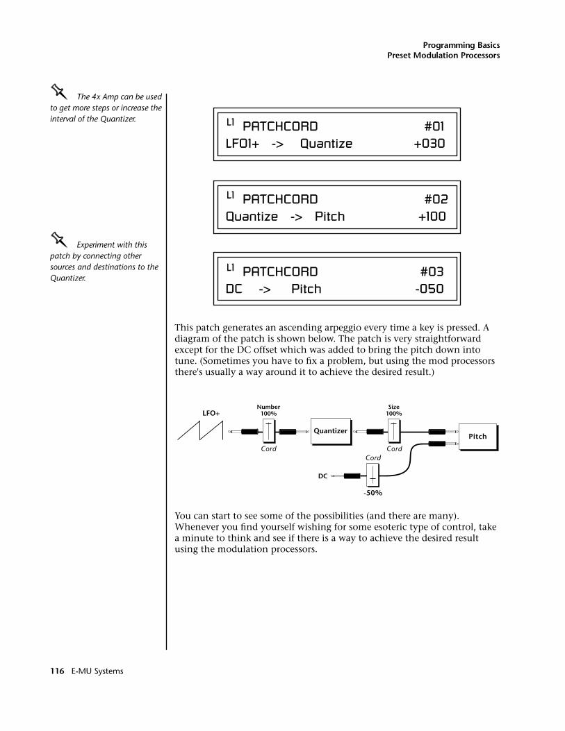
Programming BasicsPreset Modulation Processors
OOOO The 4x Amp can be used to get more steps or increase the interval of the Quantizer.
OOOO Experiment with this patch by connecting other sources and destinations to the Quantizer.
This patch generates an ascending arpeggio every time a key is pressed. A diagram of the patch is shown below. The patch is very straightforward except for the DC offset which was added to bring the pitch down into tune. (Sometimes you have to fix a problem, but using the mod processors there's usually a way around it to achieve the desired result.)
You can start to see some of the possibilities (and there are many). Whenever you find yourself wishing for some esoteric type of control, take a minute to think and see if there is a way to achieve the desired result using the modulation processors.
L1 PATCHCORD #01LFO1+ -> Quantize +030
L1 PATCHCORD #02Quantize -> Pitch +100
L1 PATCHCORD #03DC -> Pitch -050
QuantizerPitch
Number100%LFO+
DC
Size100%
Cord CordCord
-50%
116 E-MU Systems
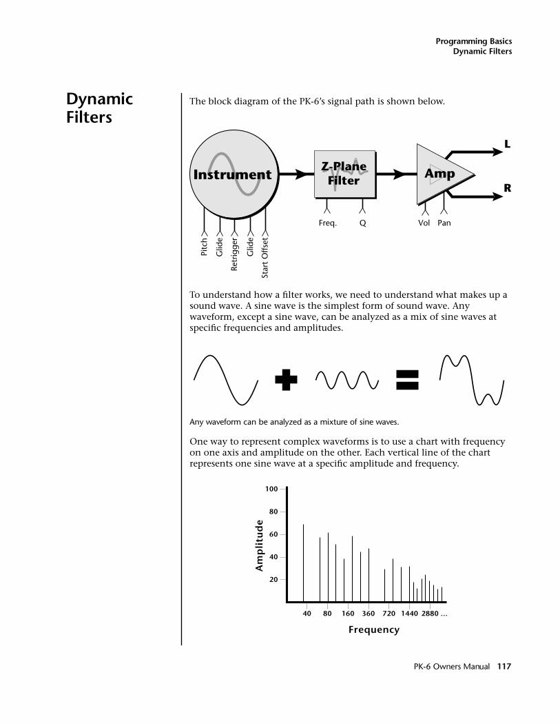
Programming BasicsDynamic Filters
Dynamic Filters
The block diagram of the PK-6’s signal path is shown below.
To understand how a filter works, we need to understand what makes up a sound wave. A sine wave is the simplest form of sound wave. Any waveform, except a sine wave, can be analyzed as a mix of sine waves at specific frequencies and amplitudes.
Any waveform can be analyzed as a mixture of sine waves.
One way to represent complex waveforms is to use a chart with frequency on one axis and amplitude on the other. Each vertical line of the chart represents one sine wave at a specific amplitude and frequency.
Instrument Amp
L
R
Freq. VolQRe
trig
ger
Pitc
h
Glid
e
Glid
e
Star
t O
ffset
Pan
Z-PlaneFilter
20
40
60
80
100
40 80 160 360 720 1440 2880
Frequency
...
Am
pli
tud
e
PK-6 Owners Manual 117
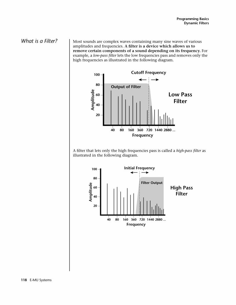
Programming BasicsDynamic Filters
What is a Filter? Most sounds are complex waves containing many sine waves of various amplitudes and frequencies. A filter is a device which allows us to remove certain components of a sound depending on its frequency. For example, a low-pass filter lets the low frequencies pass and removes only the high frequencies as illustrated in the following diagram.
A filter that lets only the high frequencies pass is called a high-pass filter as illustrated in the following diagram.
20
40
60
80
100
40 80 160 360 720 1440 2880
Frequency...
Am
plit
ude
Output of Filter
Low PassFilter
Cutoff Frequency
20
40
60
80
100
40 80 160 360 720 1440 2880
Frequency...
Am
plit
ude Filter Output
Initial Frequency
High PassFilter
118 E-MU Systems
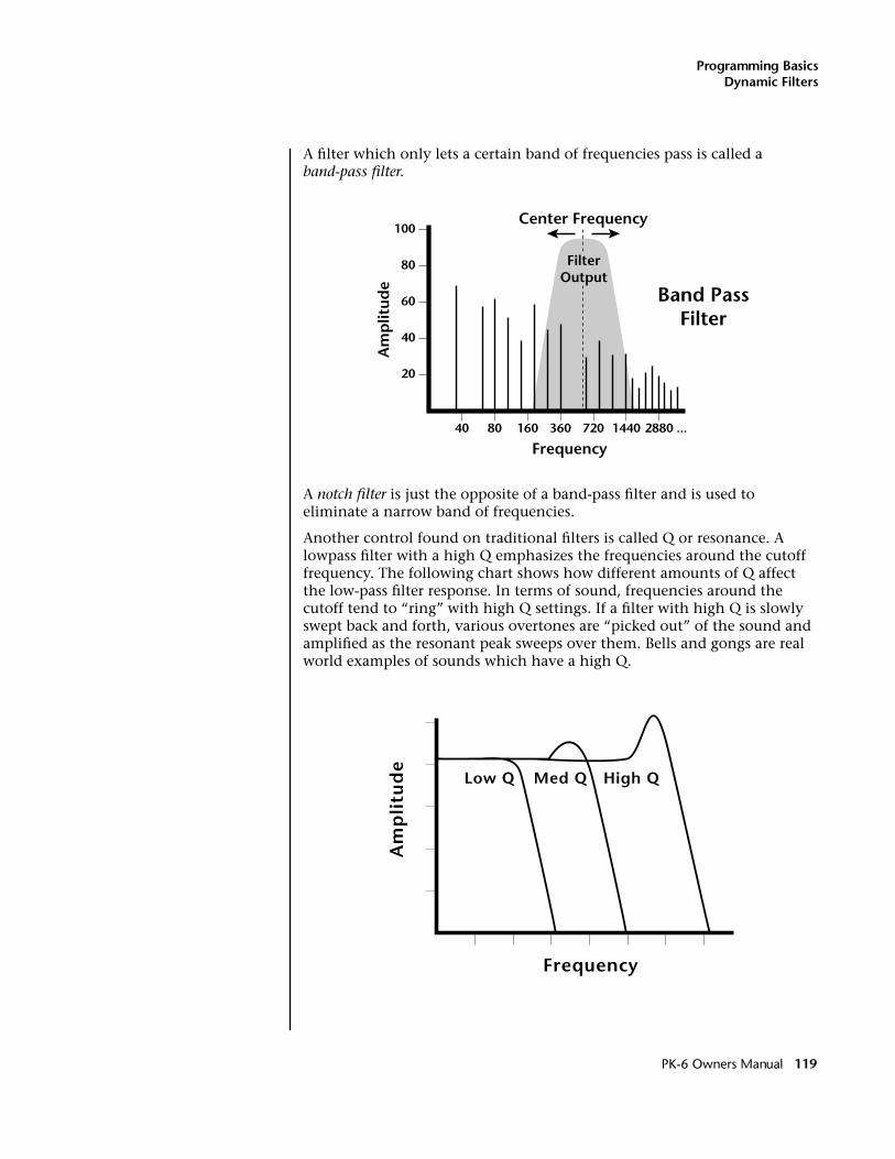
Programming BasicsDynamic Filters
A filter which only lets a certain band of frequencies pass is called a band-pass filter.
A notch filter is just the opposite of a band-pass filter and is used to eliminate a narrow band of frequencies.
Another control found on traditional filters is called Q or resonance. A lowpass filter with a high Q emphasizes the frequencies around the cutoff frequency. The following chart shows how different amounts of Q affect the low-pass filter response. In terms of sound, frequencies around the cutoff tend to “ring” with high Q settings. If a filter with high Q is slowly swept back and forth, various overtones are “picked out” of the sound and amplified as the resonant peak sweeps over them. Bells and gongs are real world examples of sounds which have a high Q.
20
40
60
80
100
40 80 160 360 720 1440 2880
Frequency...
Am
plit
ude
Center Frequency
FilterOutput
Band PassFilter
Frequency
Am
pli
tud
e
Low Q Med Q High Q
PK-6 Owners Manual 119
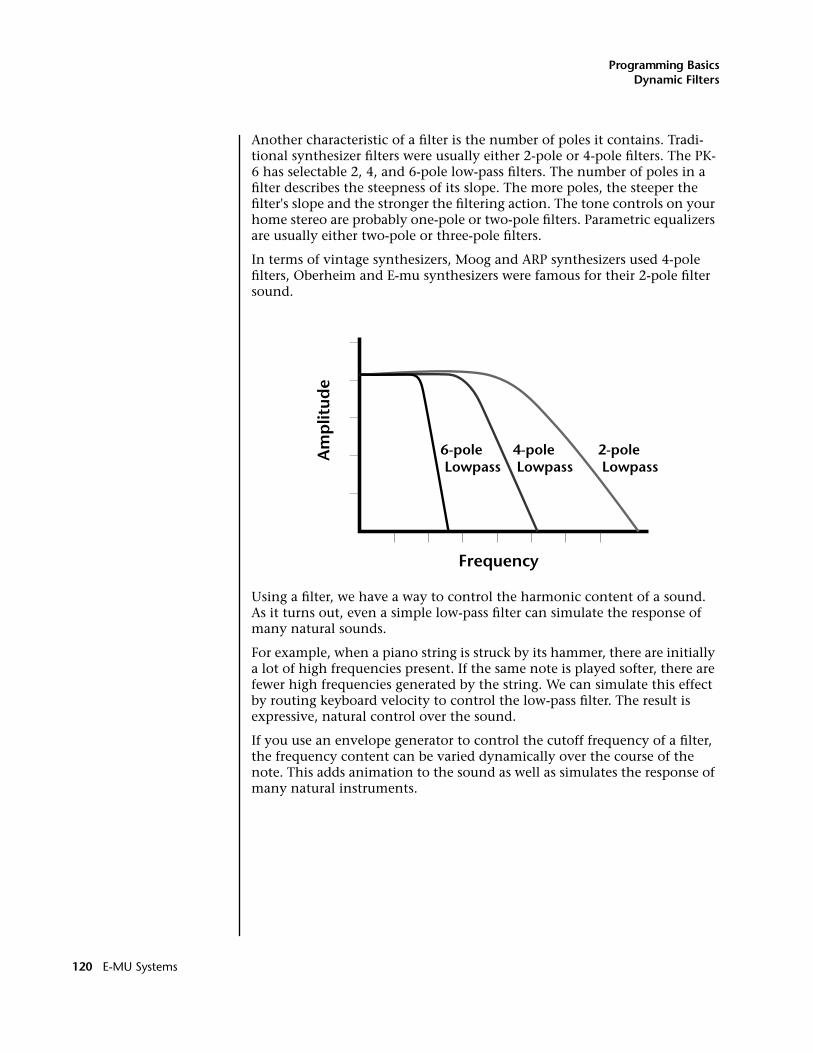
Programming BasicsDynamic Filters
Another characteristic of a filter is the number of poles it contains. Tradi-tional synthesizer filters were usually either 2-pole or 4-pole filters. The PK-6 has selectable 2, 4, and 6-pole low-pass filters. The number of poles in a filter describes the steepness of its slope. The more poles, the steeper the filter's slope and the stronger the filtering action. The tone controls on your home stereo are probably one-pole or two-pole filters. Parametric equalizers are usually either two-pole or three-pole filters.
In terms of vintage synthesizers, Moog and ARP synthesizers used 4-pole filters, Oberheim and E-mu synthesizers were famous for their 2-pole filter sound.
Using a filter, we have a way to control the harmonic content of a sound. As it turns out, even a simple low-pass filter can simulate the response of many natural sounds.
For example, when a piano string is struck by its hammer, there are initially a lot of high frequencies present. If the same note is played softer, there are fewer high frequencies generated by the string. We can simulate this effect by routing keyboard velocity to control the low-pass filter. The result is expressive, natural control over the sound.
If you use an envelope generator to control the cutoff frequency of a filter, the frequency content can be varied dynamically over the course of the note. This adds animation to the sound as well as simulates the response of many natural instruments.
Frequency
Am
plit
ude
4-pole Lowpass
6-pole Lowpass
2-pole Lowpass
120 E-MU Systems
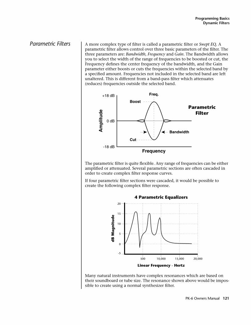
Programming BasicsDynamic Filters
Parametric Filters A more complex type of filter is called a parametric filter or Swept EQ. A parametric filter allows control over three basic parameters of the filter. The three parameters are: Bandwidth, Frequency and Gain. The Bandwidth allows you to select the width of the range of frequencies to be boosted or cut, the Frequency defines the center frequency of the bandwidth, and the Gain parameter either boosts or cuts the frequencies within the selected band by a specified amount. Frequencies not included in the selected band are left unaltered. This is different from a band-pass filter which attenuates (reduces) frequencies outside the selected band.
The parametric filter is quite flexible. Any range of frequencies can be either amplified or attenuated. Several parametric sections are often cascaded in order to create complex filter response curves.
If four parametric filter sections were cascaded, it would be possible to create the following complex filter response.
Many natural instruments have complex resonances which are based on their soundboard or tube size. The resonance shown above would be impos-sible to create using a normal synthesizer filter.
Boost
Cut
Freq.
0 dB
+18 dB
-18 dB
Bandwidth
Frequency
Am
plit
ud
eParametric
Filter
10
Linear Frequency - Hertz
dB
Mag
nit
ud
e
-5
0
5
15
20
500 10,000 15,000 20,000
4 Parametric Equalizers
PK-6 Owners Manual 121
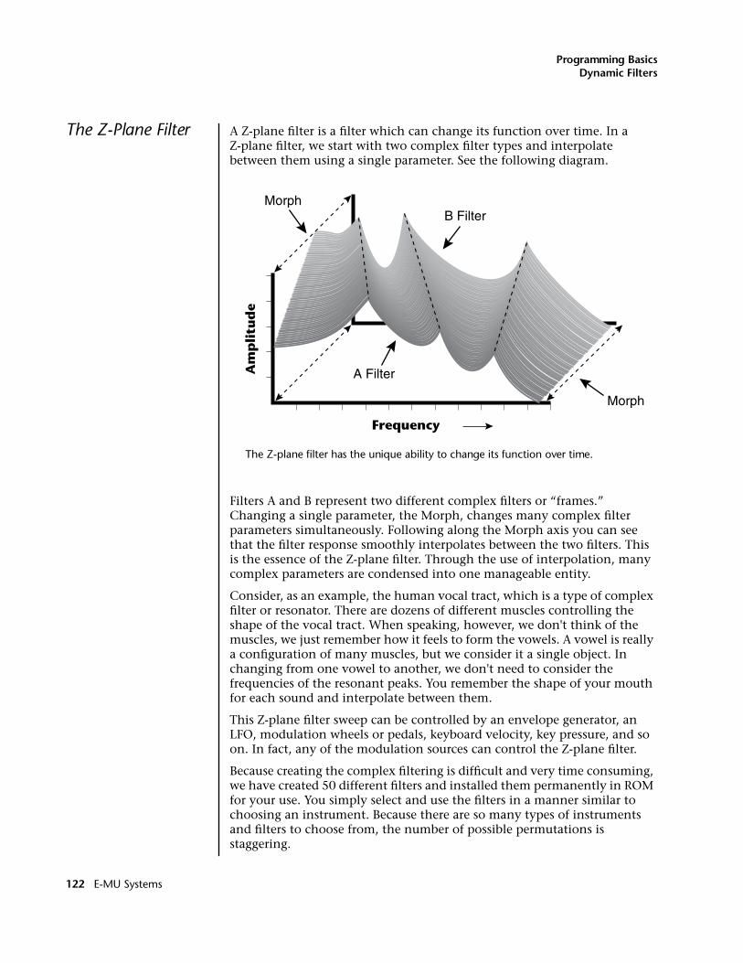
Programming BasicsDynamic Filters
The Z-Plane Filter A Z-plane filter is a filter which can change its function over time. In a Z-plane filter, we start with two complex filter types and interpolate between them using a single parameter. See the following diagram.
The Z-plane filter has the unique ability to change its function over time.
Filters A and B represent two different complex filters or “frames.” Changing a single parameter, the Morph, changes many complex filter parameters simultaneously. Following along the Morph axis you can see that the filter response smoothly interpolates between the two filters. This is the essence of the Z-plane filter. Through the use of interpolation, many complex parameters are condensed into one manageable entity.
Consider, as an example, the human vocal tract, which is a type of complex filter or resonator. There are dozens of different muscles controlling the shape of the vocal tract. When speaking, however, we don't think of the muscles, we just remember how it feels to form the vowels. A vowel is really a configuration of many muscles, but we consider it a single object. In changing from one vowel to another, we don't need to consider the frequencies of the resonant peaks. You remember the shape of your mouth for each sound and interpolate between them.
This Z-plane filter sweep can be controlled by an envelope generator, an LFO, modulation wheels or pedals, keyboard velocity, key pressure, and so on. In fact, any of the modulation sources can control the Z-plane filter.
Because creating the complex filtering is difficult and very time consuming, we have created 50 different filters and installed them permanently in ROM for your use. You simply select and use the filters in a manner similar to choosing an instrument. Because there are so many types of instruments and filters to choose from, the number of possible permutations is staggering.
Frequency
Am
pli
tud
e
Morph
Morph
B Filter
A Filter
122 E-MU Systems
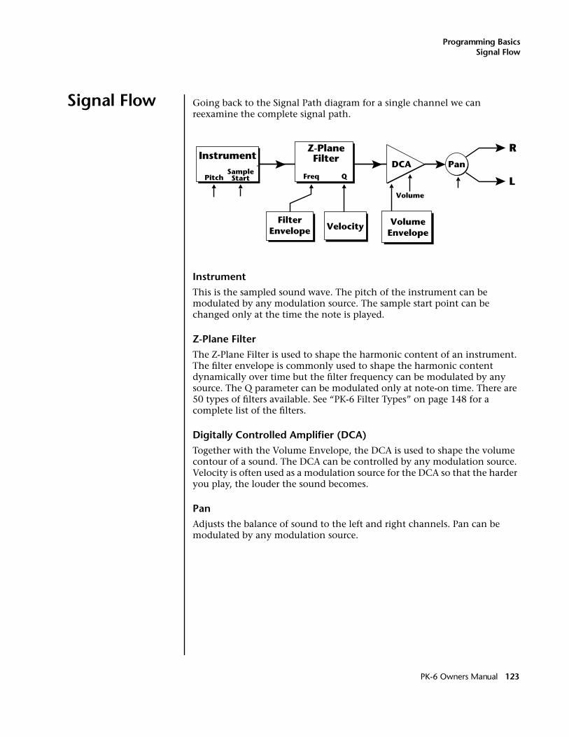
Programming BasicsSignal Flow
Signal Flow Going back to the Signal Path diagram for a single channel we can reexamine the complete signal path.
InstrumentThis is the sampled sound wave. The pitch of the instrument can be modulated by any modulation source. The sample start point can be changed only at the time the note is played.
Z-Plane FilterThe Z-Plane Filter is used to shape the harmonic content of an instrument. The filter envelope is commonly used to shape the harmonic content dynamically over time but the filter frequency can be modulated by any source. The Q parameter can be modulated only at note-on time. There are 50 types of filters available. See “PK-6 Filter Types” on page 148 for a complete list of the filters.
Digitally Controlled Amplifier (DCA)Together with the Volume Envelope, the DCA is used to shape the volume contour of a sound. The DCA can be controlled by any modulation source. Velocity is often used as a modulation source for the DCA so that the harder you play, the louder the sound becomes.
PanAdjusts the balance of sound to the left and right channels. Pan can be modulated by any modulation source.
R
LVolume
Pan
VolumeEnvelope
Instrument
PitchSampleStart
Z-PlaneFilter
DCA
FilterEnvelope Velocity
Freq Q
PK-6 Owners Manual 123
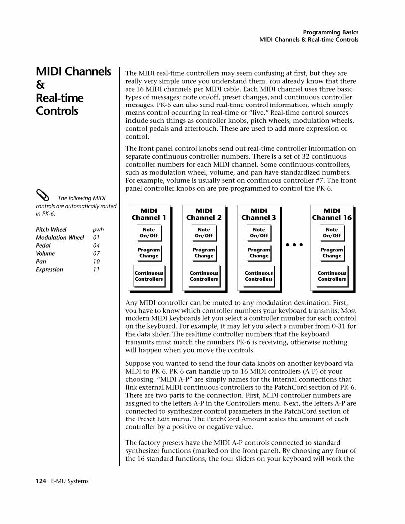
Programming BasicsMIDI Channels & Real-time Controls
MIDI Channels &Real-time Controls
The MIDI real-time controllers may seem confusing at first, but they are really very simple once you understand them. You already know that there are 16 MIDI channels per MIDI cable. Each MIDI channel uses three basic types of messages; note on/off, preset changes, and continuous controller messages. PK-6 can also send real-time control information, which simply means control occurring in real-time or “live.” Real-time control sources include such things as controller knobs, pitch wheels, modulation wheels, control pedals and aftertouch. These are used to add more expression or control.
The front panel control knobs send out real-time controller information on separate continuous controller numbers. There is a set of 32 continuous controller numbers for each MIDI channel. Some continuous controllers, such as modulation wheel, volume, and pan have standardized numbers. For example, volume is usually sent on continuous controller #7. The front panel controller knobs on are pre-programmed to control the PK-6.
The following MIDI controls are automatically routed in PK-6:
Pitch Wheel pwhModulation Wheel 01Pedal 04Volume 07Pan 10Expression 11
Any MIDI controller can be routed to any modulation destination. First, you have to know which controller numbers your keyboard transmits. Most modern MIDI keyboards let you select a controller number for each control on the keyboard. For example, it may let you select a number from 0-31 for the data slider. The realtime controller numbers that the keyboard transmits must match the numbers PK-6 is receiving, otherwise nothing will happen when you move the controls.
Suppose you wanted to send the four data knobs on another keyboard via MIDI to PK-6. PK-6 can handle up to 16 MIDI controllers (A-P) of your choosing. “MIDI A-P” are simply names for the internal connections that link external MIDI continuous controllers to the PatchCord section of PK-6. There are two parts to the connection. First, MIDI controller numbers are assigned to the letters A-P in the Controllers menu. Next, the letters A-P are connected to synthesizer control parameters in the PatchCord section of the Preset Edit menu. The PatchCord Amount scales the amount of each controller by a positive or negative value.
The factory presets have the MIDI A-P controls connected to standard synthesizer functions (marked on the front panel). By choosing any four of the 16 standard functions, the four sliders on your keyboard will work the
NoteOn/Off
ContinuousControllers
MIDIChannel 16
ProgramChange
NoteOn/Off
ContinuousControllers
MIDIChannel 3
ProgramChange
NoteOn/Off
ContinuousControllers
MIDIChannel 2
ProgramChange
NoteOn/Off
ContinuousControllers
MIDIChannel 1
ProgramChange
124 E-MU Systems
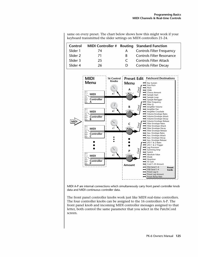
Programming BasicsMIDI Channels & Real-time Controls
same on every preset. The chart below shows how this might work if your keyboard transmitted the slider settings on MIDI controllers 21-24.
Control MIDI Controller # Routing Standard FunctionSlider 1 74 A Controls Filter FrequencySlider 2 71 B Controls Filter ResonanceSlider 3 25 C Controls Filter AttackSlider 4 26 D Controls Filter Decay
MIDI A-P are internal connections which simultaneously carry front panel controller knob data and MIDI continuous controller data.
The front panel controller knobs work just like MIDI real-time controllers. The four controller knobs can be assigned to the 16 controllers A-P. The front panel knob and incoming MIDI controller messages assigned to that letter, both control the same parameter that you select in the PatchCord screen.
Patchcord Destinations16 ControlKnobs
+-
MIDIMenu
Preset EditMenu
A
B
C
P
MIDI
Amount
+-
+-
+-
A
B
C
P
Cor
dC
ord
Cor
dC
ord
Key SustainFine PitchPitchGlideChorus AmountSample StartSample LoopSample RetriggerFilter FrequencyFilter QAmplifier VolumeAmplifier PanAmplifier CrossfadeVolume Envelope RatesVolume Envelope AttackVolume Envelope DecayVolume Envelope ReleaseFilter Envelope RatesFilter Envelope AttackFilter Envelope DecayFilter Envelope ReleaseAux. Envelope RatesAux. Envelope AttackAux. Envelope DecayAux. Envelope ReleaseLFO 1 & 2 RatesLFO 1 & 2 TriggerLag ProcessorSumming AmpSwitchAbsolute ValueDiodeQuantizer4x GainCord 1-24 Amount
FXA Send 1-4 FXB Send 1-4Preset Lag InPreset Lag AmountPreset Ramp Rate
PresetCords
012 MIDI
ControllerA
31
95
64
012 MIDI
ControllerP
31
95
64
012 MIDI
ControllerC
31
95
64
012 MIDI
ControllerB
31
95
64
PK-6 Owners Manual 125
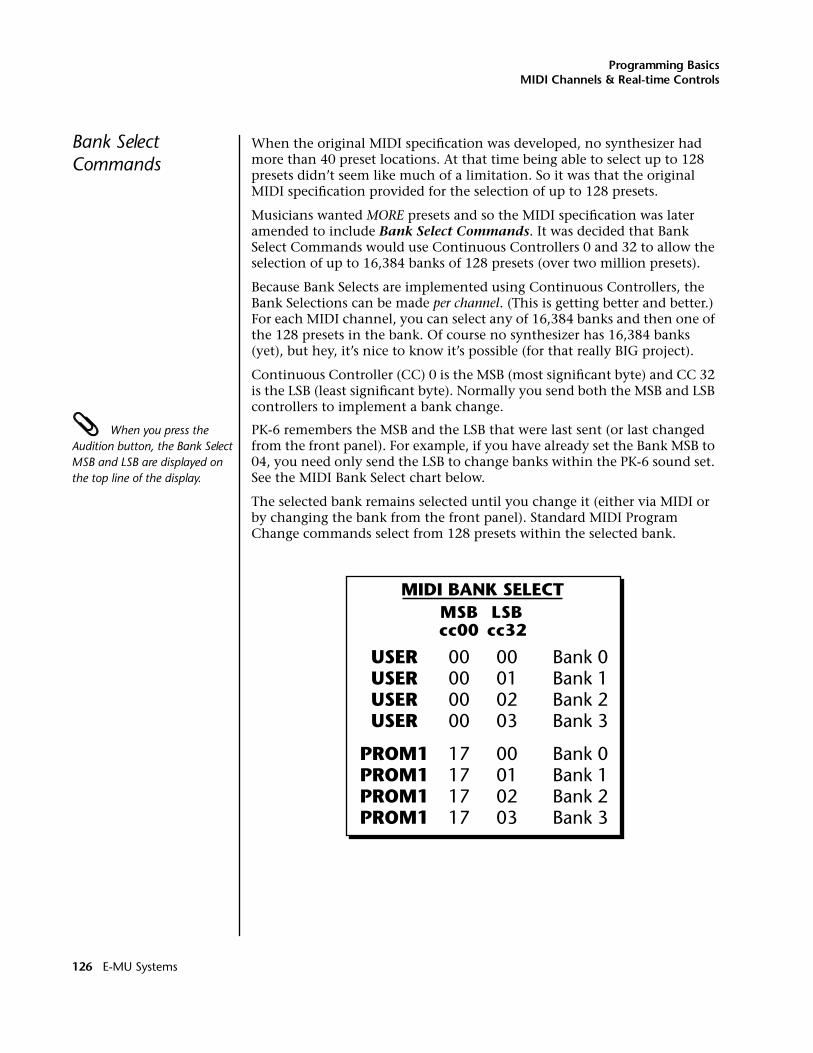
Programming BasicsMIDI Channels & Real-time Controls
Bank Select Commands
When the original MIDI specification was developed, no synthesizer had more than 40 preset locations. At that time being able to select up to 128 presets didn’t seem like much of a limitation. So it was that the original MIDI specification provided for the selection of up to 128 presets.
Musicians wanted MORE presets and so the MIDI specification was later amended to include Bank Select Commands. It was decided that Bank Select Commands would use Continuous Controllers 0 and 32 to allow the selection of up to 16,384 banks of 128 presets (over two million presets).
Because Bank Selects are implemented using Continuous Controllers, the Bank Selections can be made per channel. (This is getting better and better.) For each MIDI channel, you can select any of 16,384 banks and then one of the 128 presets in the bank. Of course no synthesizer has 16,384 banks (yet), but hey, it’s nice to know it’s possible (for that really BIG project).
Continuous Controller (CC) 0 is the MSB (most significant byte) and CC 32 is the LSB (least significant byte). Normally you send both the MSB and LSB controllers to implement a bank change.
When you press the Audition button, the Bank Select MSB and LSB are displayed on the top line of the display.
PK-6 remembers the MSB and the LSB that were last sent (or last changed from the front panel). For example, if you have already set the Bank MSB to 04, you need only send the LSB to change banks within the PK-6 sound set. See the MIDI Bank Select chart below.
The selected bank remains selected until you change it (either via MIDI or by changing the bank from the front panel). Standard MIDI Program Change commands select from 128 presets within the selected bank.
PROM1PROM1PROM1PROM1
Bank 0Bank 1Bank 2Bank 3
Bank 0Bank 1Bank 2Bank 3
00000000
17171717
00010203
00010203
USERUSERUSERUSER
MIDI BANK SELECT
cc00 cc32MSB LSB
126 E-MU Systems
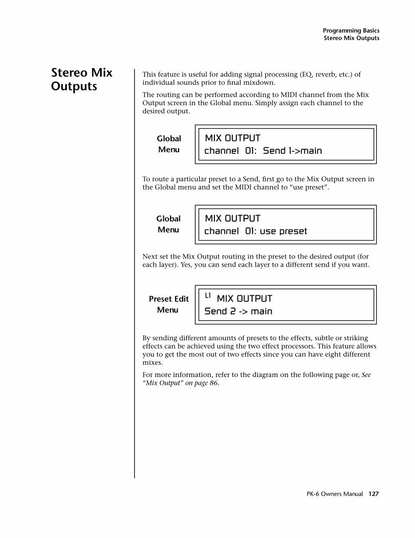
Programming BasicsStereo Mix Outputs
Stereo Mix Outputs
This feature is useful for adding signal processing (EQ, reverb, etc.) of individual sounds prior to final mixdown.
The routing can be performed according to MIDI channel from the Mix Output screen in the Global menu. Simply assign each channel to the desired output.
To route a particular preset to a Send, first go to the Mix Output screen in the Global menu and set the MIDI channel to “use preset”.
Next set the Mix Output routing in the preset to the desired output (for each layer). Yes, you can send each layer to a different send if you want.
By sending different amounts of presets to the effects, subtle or striking effects can be achieved using the two effect processors. This feature allows you to get the most out of two effects since you can have eight different mixes.
For more information, refer to the diagram on the following page or, See “Mix Output” on page 86.
MIX OUTPUTchannel 01: Send 1->main
GlobalMenu
MIX OUTPUTchannel 01: use preset
GlobalMenu
L1 MIX OUTPUTSend 2 -> main
Preset EditMenu
PK-6 Owners Manual 127
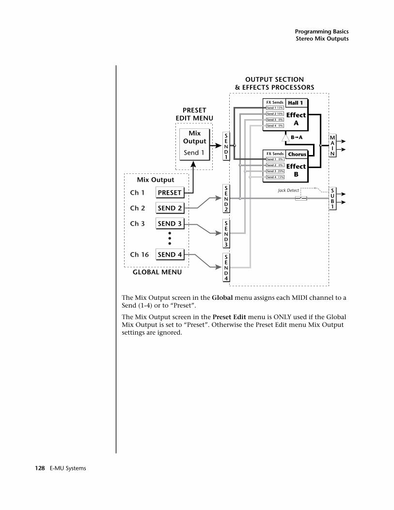
Programming BasicsStereo Mix Outputs
The Mix Output screen in the Global menu assigns each MIDI channel to a Send (1-4) or to “Preset”.
The Mix Output screen in the Preset Edit menu is ONLY used if the Global Mix Output is set to “Preset”. Otherwise the Preset Edit menu Mix Output settings are ignored.
SUB1
MAIN
OUTPUT SECTION& EFFECTS PROCESSORS
FX Sends Hall 1
EffectA
FX Sends Chorus
EffectB
B➟A
Jack DetectPRESET
MixOutput
Mix Output
Send 1
Send 1 15%
Send 2 10%
Send 3 0%
Send 4 0%
Send 1 0%
Send 2 0%
Send 3 20%
Send 4 15%
GLOBAL MENU
PRESETEDIT MENU
Ch 1
SEND 2Ch 2
SEND 3Ch 3
SEND 4Ch 16
SEND1
SEND2
SEND3
SEND4
128 E-MU Systems
Preset Edit Menu
The Preset Edit Menu contains four layers of preset parameters that you can modify and then save as preset information in one of the user preset locations. There are four instrument layers in the Preset Edit menu. See the illustration on page 130 for a description of the Preset Layer model.
While the Preset Edit menu is activated, all incoming MIDI preset changes on the selected channel are ignored.
� To Access the Preset Edit Menu:Press the Preset Edit button, lighting the LED. The Preset Edit Menu screen displays the menu page most recently selected since powering up PK-6. The cursor appears below the first character of the screen heading on line one.
� To Scroll through Layers:Place the cursor below the layer field. Rotate the data entry control to select a layer (1-4).
____ If there is no “A” option in the Layer field, you must enable the “Edit All Layers” function in the Global Menu (page 92).
You can also select All Layers by choosing “A” in the layer field. When All Layers is selected, the existing parameter value for any field will be displayed if the values of all four layers are equal. If the values of all four layers are NOT equal, the value of layer 1 will be displayed with flashing characters. If you change the parameter value, all layers will assume the new value and the display will stop flashing.
� To Scroll through Pages:Whenever you are in the Preset Edit menu, the sixteen command buttons function as “jump” buttons to various screens in the Preset Edit menu, which are labelled below each button. Pressing a jump button instantly takes you to the first screen in the selected category. Pressing the button again takes you to the second screen in the category and so on. Repeated pressing will rotate you back to the first screen in the category.
You can also change pages by placing the cursor below the page title field. This will automatically be done when you press the Home/Enter button. Rotate the data entry control to scroll through the pages.
� To Change a Parameter:Place the cursor below the parameter field. Rotate the data entry control to change the parameter value.
PK-6 Owners Manual 129
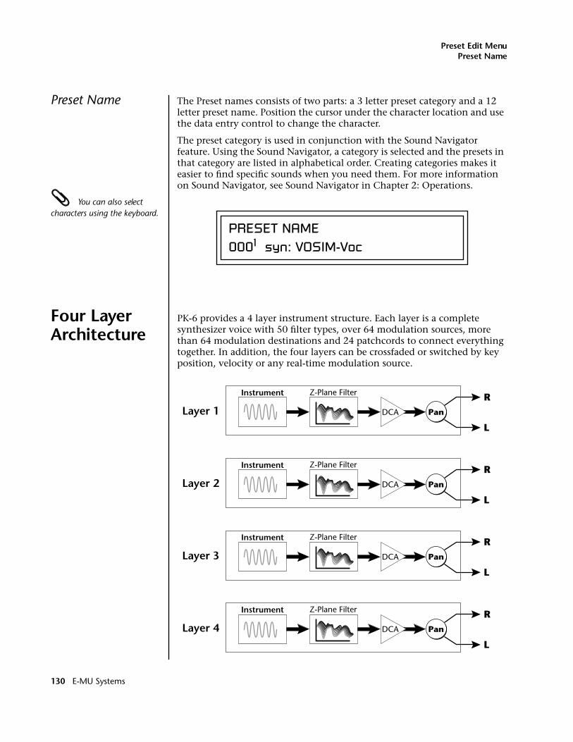
Preset Edit MenuPreset Name
Preset Name The Preset names consists of two parts: a 3 letter preset category and a 12 letter preset name. Position the cursor under the character location and use the data entry control to change the character.
The preset category is used in conjunction with the Sound Navigator feature. Using the Sound Navigator, a category is selected and the presets in that category are listed in alphabetical order. Creating categories makes it easier to find specific sounds when you need them. For more information on Sound Navigator, see Sound Navigator in Chapter 2: Operations.
You can also select characters using the keyboard.
Four Layer Architecture
PK-6 provides a 4 layer instrument structure. Each layer is a complete synthesizer voice with 50 filter types, over 64 modulation sources, more than 64 modulation destinations and 24 patchcords to connect everything together. In addition, the four layers can be crossfaded or switched by key position, velocity or any real-time modulation source.
PRESET NAME0001 syn: VOSIM-Voc
Instrument
Layer 1
Z-Plane Filter
DCA
R
L
Pan
Instrument
Layer 2
Z-Plane Filter
DCA
R
L
Pan
Instrument
Layer 3
Z-Plane Filter
DCA
R
L
Pan
Instrument
Layer 4
Z-Plane Filter
DCA
R
L
Pan
130 E-MU Systems
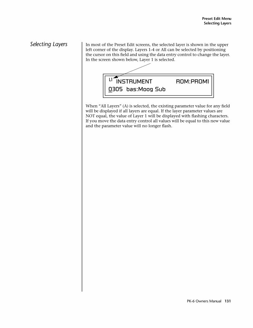
Preset Edit MenuSelecting Layers
Selecting Layers In most of the Preset Edit screens, the selected layer is shown in the upper left corner of the display. Layers 1-4 or All can be selected by positioning the cursor on this field and using the data entry control to change the layer. In the screen shown below, Layer 1 is selected.
When “All Layers” (A) is selected, the existing parameter value for any field will be displayed if all layers are equal. If the layer parameter values are NOT equal, the value of Layer 1 will be displayed with flashing characters. If you move the data entry control all values will be equal to this new value and the parameter value will no longer flash.
L1 INSTRUMENT ROM:PROM10305 bas:Moog Sub
PK-6 Owners Manual 131
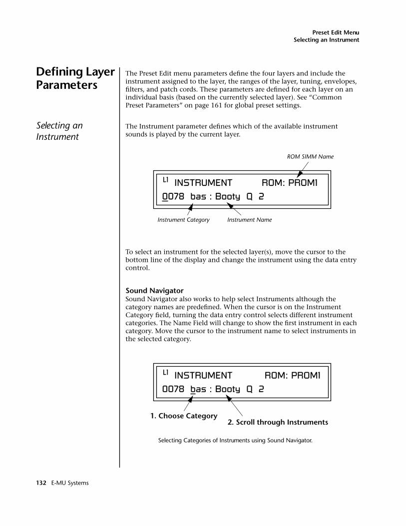
Preset Edit MenuSelecting an Instrument
Defining Layer Parameters
The Preset Edit menu parameters define the four layers and include the instrument assigned to the layer, the ranges of the layer, tuning, envelopes, filters, and patch cords. These parameters are defined for each layer on an individual basis (based on the currently selected layer). See “Common Preset Parameters” on page 161 for global preset settings.
Selecting an Instrument
The Instrument parameter defines which of the available instrument sounds is played by the current layer.
To select an instrument for the selected layer(s), move the cursor to the bottom line of the display and change the instrument using the data entry control.
Sound NavigatorSound Navigator also works to help select Instruments although the category names are predefined. When the cursor is on the Instrument Category field, turning the data entry control selects different instrument categories. The Name Field will change to show the first instrument in each category. Move the cursor to the instrument name to select instruments in the selected category.
Selecting Categories of Instruments using Sound Navigator.
L1 INSTRUMENT ROM: PROM1
ROM SIMM Name
0078 bas : Booty Q 2
Instrument Category Instrument Name
L1 INSTRUMENT ROM: PROM1
0078 bas : Booty Q 2
1. Choose Category2. Scroll through Instruments
132 E-MU Systems
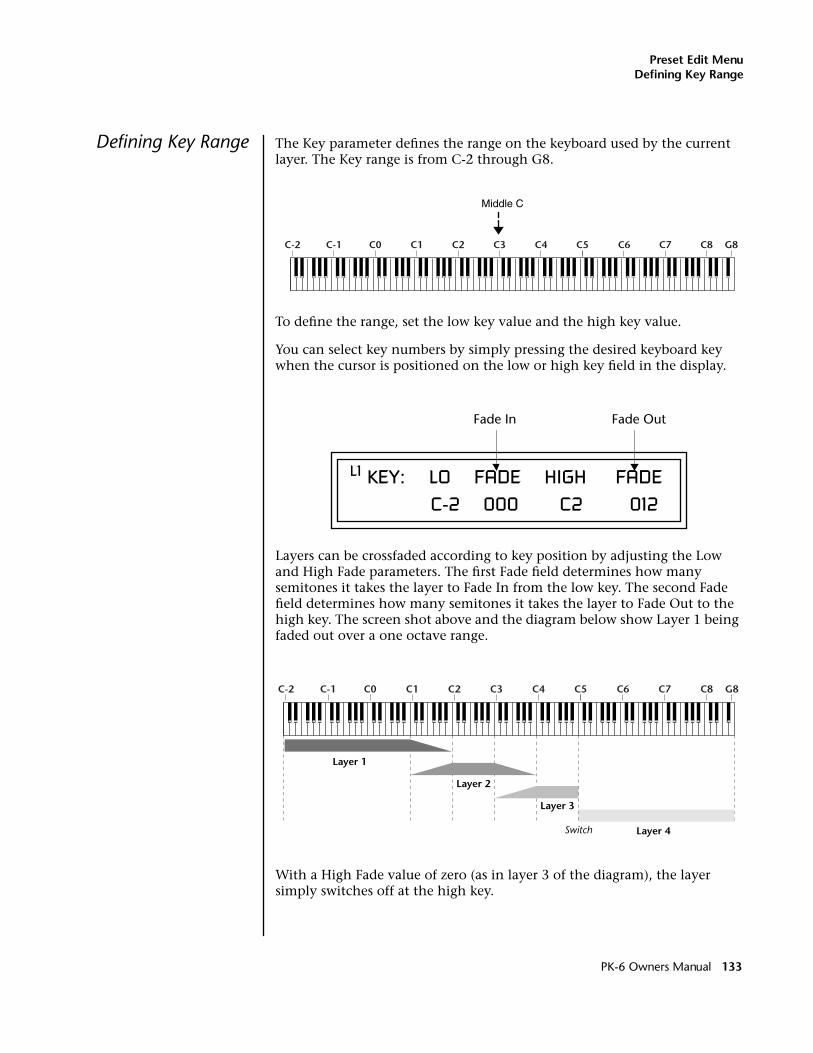
Preset Edit MenuDefining Key Range
Defining Key Range The Key parameter defines the range on the keyboard used by the current layer. The Key range is from C-2 through G8.
To define the range, set the low key value and the high key value.
You can select key numbers by simply pressing the desired keyboard key when the cursor is positioned on the low or high key field in the display.
Layers can be crossfaded according to key position by adjusting the Low and High Fade parameters. The first Fade field determines how many semitones it takes the layer to Fade In from the low key. The second Fade field determines how many semitones it takes the layer to Fade Out to the high key. The screen shot above and the diagram below show Layer 1 being faded out over a one octave range.
With a High Fade value of zero (as in layer 3 of the diagram), the layer simply switches off at the high key.
C-2 C-1 C0 C1 C2 C3 C4 C5 C6 C7 C8 G8
Middle C
L1 KEY: LO FADE HIGH FADE C-2 000 C2 012
Fade In Fade Out
C-2 C-1 C0 C1 C2 C3 C4 C5 C6 C7 C8 G8
Layer 1
Layer 2
Layer 3
Layer 4Switch
PK-6 Owners Manual 133
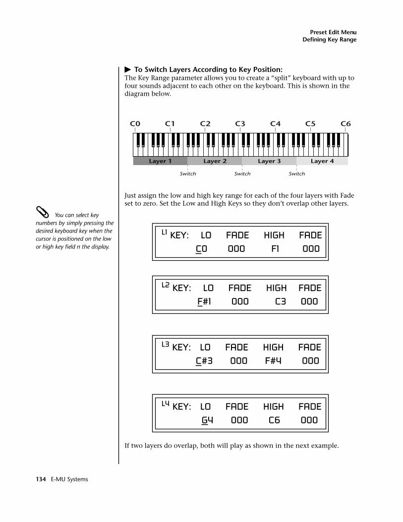
Preset Edit MenuDefining Key Range
� To Switch Layers According to Key Position:The Key Range parameter allows you to create a “split” keyboard with up to four sounds adjacent to each other on the keyboard. This is shown in the diagram below.
Just assign the low and high key range for each of the four layers with Fade set to zero. Set the Low and High Keys so they don’t overlap other layers.
You can select key numbers by simply pressing the desired keyboard key when the cursor is positioned on the low or high key field n the display.
If two layers do overlap, both will play as shown in the next example.
C0 C1 C2 C3 C4 C5 C6
Layer 1 Layer 2 Layer 3 Layer 4
Switch Switch Switch
L1 KEY: LO FADE HIGH FADE C0 000 F1 000
L2 KEY: LO FADE HIGH FADE F#1 000 C3 000
L3 KEY: LO FADE HIGH FADE C#3 000 F#4 000
L4 KEY: LO FADE HIGH FADE G4 000 C6 000
134 E-MU Systems
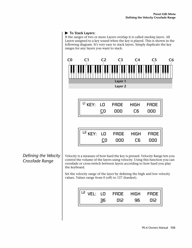
Preset Edit MenuDefining the Velocity Crossfade Range
� To Stack Layers:If the ranges of two or more Layers overlap it is called stacking layers. All Layers assigned to a key sound when the key is played. This is shown in the following diagram. It’s very easy to stack layers. Simply duplicate the key ranges for any layers you want to stack.
Defining the Velocity Crossfade Range
Velocity is a measure of how hard the key is pressed. Velocity Range lets you control the volume of the layers using velocity. Using this function you can crossfade or cross-switch between layers according to how hard you play the keyboard.
Set the velocity range of the layer by defining the high and low velocity values. Values range from 0 (off) to 127 (hardest).
C0 C1 C2 C3 C4 C5 C6
Layer 1
Layer 2
L1 KEY: LO FADE HIGH FADE C0 000 C6 000
L2 KEY: LO FADE HIGH FADE C0 000 C6 000
L2 VEL: LO FADE HIGH FADE 36 012 96 012
PK-6 Owners Manual 135
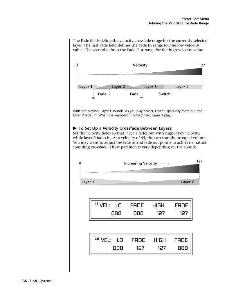
Preset Edit MenuDefining the Velocity Crossfade Range
The Fade fields define the velocity crossfade range for the currently selected layer. The first Fade field defines the Fade In range for the low velocity value. The second defines the Fade Out range for the high velocity value.
With soft playing, Layer 1 sounds. As you play harder, Layer 1 gradually fades out and Layer 2 fades in. When the keyboard is played hard, Layer 3 plays.
� To Set Up a Velocity Crossfade Between Layers:Set the velocity fades so that layer 1 fades out with higher key velocity, while layer 2 fades in. At a velocity of 64, the two sounds are equal volume. You may want to adjust the fade in and fade out points to achieve a natural sounding crossfade. These parameters vary depending on the sounds.
Layer 1 Layer 2 Layer 3
Velocity
Layer 4
0 127
Fade Fade Switch36 96
Increasing Velocity0 127
Layer 2Layer 1 Layer 2Layer 1
L1 VEL: LO FADE HIGH FADE 000 000 127 127
L2 VEL: LO FADE HIGH FADE 000 127 127 000
136 E-MU Systems
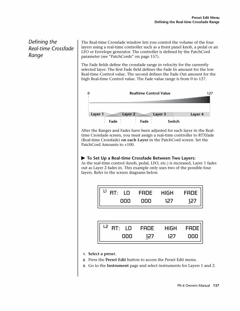
Preset Edit MenuDefining the Real-time Crossfade Range
Defining the Real-time Crossfade Range
The Real-time Crossfade window lets you control the volume of the four layers using a real-time controller such as a front panel knob, a pedal or an LFO or Envelope generator. The controller is defined by the PatchCord parameter (see “PatchCords” on page 157).
The Fade fields define the crossfade range in velocity for the currently selected layer. The first Fade field defines the Fade In amount for the low Real-time Control value. The second defines the Fade Out amount for the high Real-time Control value. The Fade value range is from 0 to 127.
After the Ranges and Fades have been adjusted for each layer in the Real-time Crossfade screen, you must assign a real-time controller to RTXfade (Real-time Crossfade) on each Layer in the PatchCord screen. Set the PatchCord Amounts to +100.
� To Set Up a Real-time Crossfade Between Two Layers:As the real-time control (knob, pedal, LFO, etc.) is increased, Layer 1 fades out as Layer 2 fades in. This example only uses two of the possible four layers. Refer to the screen diagrams below.
1. Select a preset.
2. Press the Preset Edit button to access the Preset Edit menu.
3. Go to the Instrument page and select instruments for Layers 1 and 2.
Layer 1 Layer 2 Layer 3
Fade
Realtime Control Value
Layer 4
0 127
Fade Switch
L1 RT: LO FADE HIGH FADE 000 000 127 127
L2 RT: LO FADE HIGH FADE 000 127 127 000
PK-6 Owners Manual 137
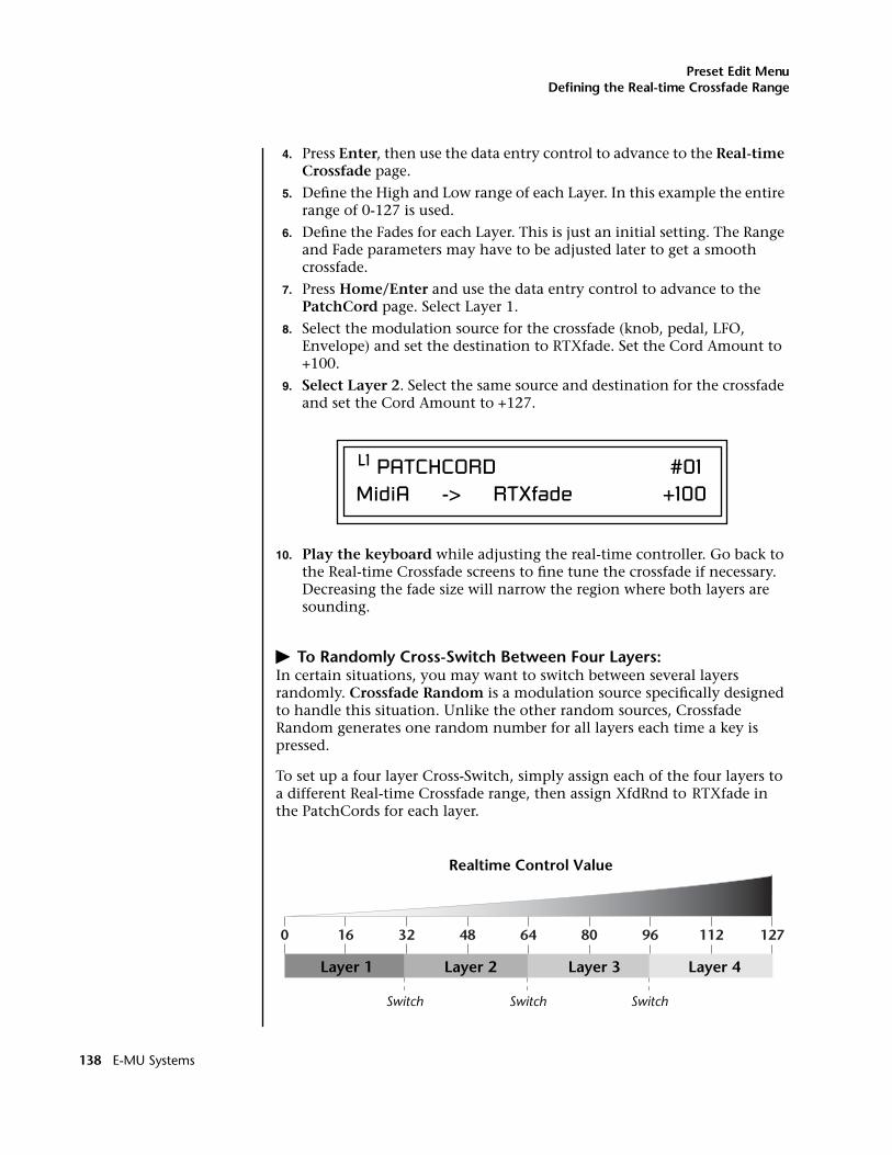
Preset Edit MenuDefining the Real-time Crossfade Range
4. Press Enter, then use the data entry control to advance to the Real-time Crossfade page.
5. Define the High and Low range of each Layer. In this example the entire range of 0-127 is used.
6. Define the Fades for each Layer. This is just an initial setting. The Range and Fade parameters may have to be adjusted later to get a smooth crossfade.
7. Press Home/Enter and use the data entry control to advance to the PatchCord page. Select Layer 1.
8. Select the modulation source for the crossfade (knob, pedal, LFO, Envelope) and set the destination to RTXfade. Set the Cord Amount to +100.
9. Select Layer 2. Select the same source and destination for the crossfade and set the Cord Amount to +127.
10. Play the keyboard while adjusting the real-time controller. Go back to the Real-time Crossfade screens to fine tune the crossfade if necessary. Decreasing the fade size will narrow the region where both layers are sounding.
� To Randomly Cross-Switch Between Four Layers:In certain situations, you may want to switch between several layers randomly. Crossfade Random is a modulation source specifically designed to handle this situation. Unlike the other random sources, Crossfade Random generates one random number for all layers each time a key is pressed.
To set up a four layer Cross-Switch, simply assign each of the four layers to a different Real-time Crossfade range, then assign XfdRnd to RTXfade in the PatchCords for each layer.
L1 PATCHCORD #01MidiA -> RTXfade +100
Layer 1 Layer 2 Layer 3 Layer 4
Switch Switch Switch
Realtime Control Value
0 127112968064483216
138 E-MU Systems
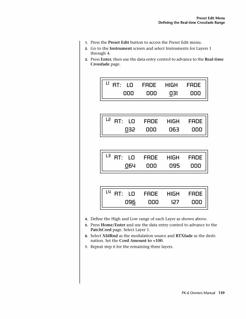
Preset Edit MenuDefining the Real-time Crossfade Range
1. Press the Preset Edit button to access the Preset Edit menu.
2. Go to the Instrument screen and select Instruments for Layers 1 through 4.
3. Press Enter, then use the data entry control to advance to the Real-time Crossfade page.
4. Define the High and Low range of each Layer as shown above.
5. Press Home/Enter and use the data entry control to advance to the PatchCord page. Select Layer 1.
6. Select XfdRnd as the modulation source and RTXfade as the desti-nation. Set the Cord Amount to +100.
7. Repeat step 6 for the remaining three layers.
L1 RT: LO FADE HIGH FADE 000 000 031 000
L2 RT: LO FADE HIGH FADE 032 000 063 000
L3 RT: LO FADE HIGH FADE 064 000 095 000
L4 RT: LO FADE HIGH FADE 096 000 127 000
PK-6 Owners Manual 139
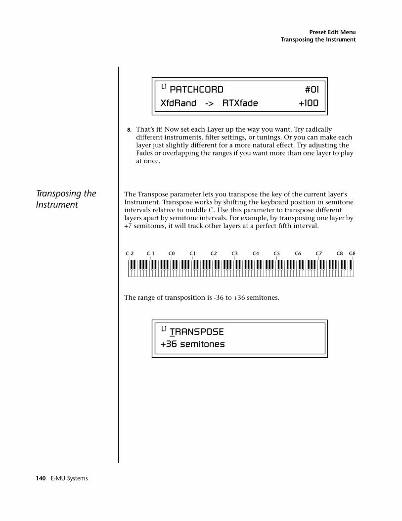
Preset Edit MenuTransposing the Instrument
8. That’s it! Now set each Layer up the way you want. Try radically different instruments, filter settings, or tunings. Or you can make each layer just slightly different for a more natural effect. Try adjusting the Fades or overlapping the ranges if you want more than one layer to play at once.
Transposing the Instrument
The Transpose parameter lets you transpose the key of the current layer’s Instrument. Transpose works by shifting the keyboard position in semitone intervals relative to middle C. Use this parameter to transpose different layers apart by semitone intervals. For example, by transposing one layer by +7 semitones, it will track other layers at a perfect fifth interval.
The range of transposition is -36 to +36 semitones.
L1 PATCHCORD #01XfdRand -> RTXfade +100
C-2 C-1 C0 C1 C2 C3 C4 C5 C6 C7 C8 G8
L1 TRANSPOSE +36 semitones
140 E-MU Systems
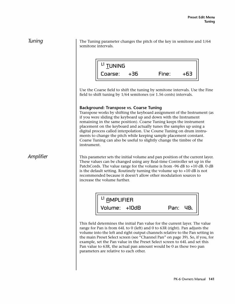
Preset Edit MenuTuning
Tuning The Tuning parameter changes the pitch of the key in semitone and 1/64 semitone intervals.
Use the Coarse field to shift the tuning by semitone intervals. Use the Fine field to shift tuning by 1/64 semitones (or 1.56 cents) intervals.
Background: Transpose vs. Coarse TuningTranspose works by shifting the keyboard assignment of the Instrument (as if you were sliding the keyboard up and down with the Instrument remaining in the same position). Coarse Tuning keeps the instrument placement on the keyboard and actually tunes the samples up using a digital process called interpolation. Use Course Tuning on drum instru-ments to change the pitch while keeping sample placement constant. Coarse Tuning can also be useful to slightly change the timbre of the instrument.
Amplifier This parameter sets the initial volume and pan position of the current layer. These values can be changed using any Real-time Controller set up in the PatchCords. The value range for the volume is from -96 dB to +10 dB. 0 dB is the default setting. Routinely turning the volume up to +10 dB is not recommended because it doesn’t allow other modulation sources to increase the volume further.
This field determines the initial Pan value for the current layer. The value range for Pan is from 64L to 0 (left) and 0 to 63R (right). Pan adjusts the volume into the left and right output channels relative to the Pan setting in the main Preset Select screen (see “Channel Pan” on page 39). So, if you, for example, set the Pan value in the Preset Select screen to 64L and set this Pan value to 63R, the actual pan amount would be 0 as these two pan parameters are relative to each other.
L1 TUNINGCoarse: +36 Fine: +63
L1 AMPLIFIER Volume: +10dB Pan: 48L
PK-6 Owners Manual 141
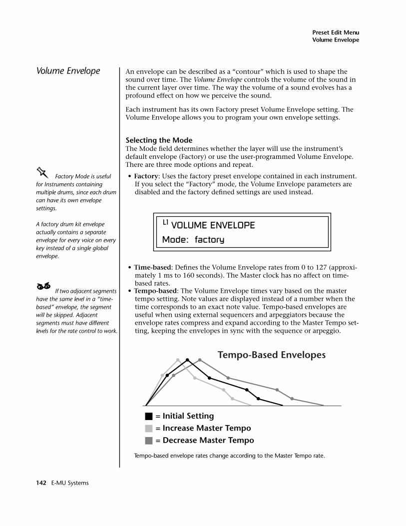
Preset Edit MenuVolume Envelope
Volume Envelope An envelope can be described as a “contour” which is used to shape the sound over time. The Volume Envelope controls the volume of the sound in the current layer over time. The way the volume of a sound evolves has a profound effect on how we perceive the sound.
Each instrument has its own Factory preset Volume Envelope setting. The Volume Envelope allows you to program your own envelope settings.
Selecting the ModeThe Mode field determines whether the layer will use the instrument’s default envelope (Factory) or use the user-programmed Volume Envelope. There are three mode options and repeat.
OOOO Factory Mode is useful for Instruments containing multiple drums, since each drum can have its own envelope settings.
A factory drum kit envelope actually contains a separate envelope for every voice on every key instead of a single global envelope.
• Factory: Uses the factory preset envelope contained in each instrument. If you select the “Factory” mode, the Volume Envelope parameters are disabled and the factory defined settings are used instead.
• Time-based: Defines the Volume Envelope rates from 0 to 127 (approxi-mately 1 ms to 160 seconds). The Master clock has no affect on time-based rates.
____ If two adjacent segments have the same level in a “time-based” envelope, the segment will be skipped. Adjacent segments must have different levels for the rate control to work.
• Tempo-based: The Volume Envelope times vary based on the master tempo setting. Note values are displayed instead of a number when the time corresponds to an exact note value. Tempo-based envelopes are useful when using external sequencers and arpeggiators because the envelope rates compress and expand according to the Master Tempo set-ting, keeping the envelopes in sync with the sequence or arpeggio.
Tempo-based envelope rates change according to the Master Tempo rate.
L1 VOLUME ENVELOPE
Mode: factory
= Initial Setting= Increase Master Tempo= Decrease Master Tempo
Tempo-Based Envelopes
142 E-MU Systems
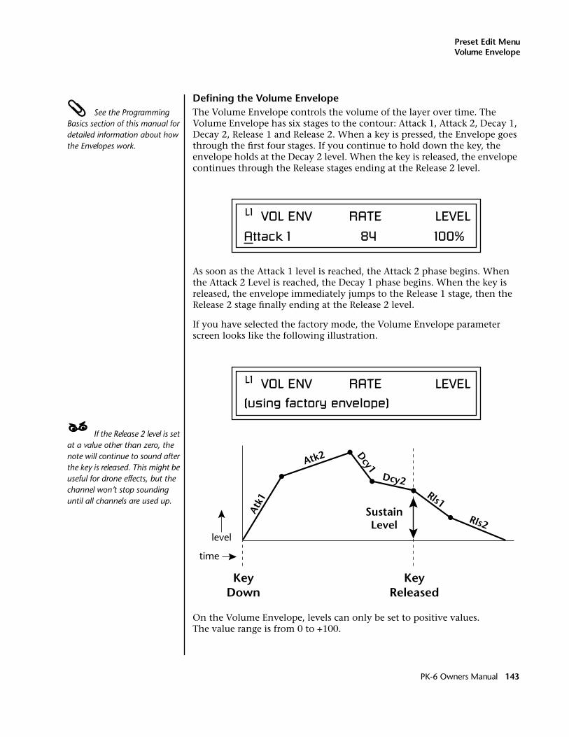
Preset Edit MenuVolume Envelope
Defining the Volume Envelope See the Programming Basics section of this manual for detailed information about how the Envelopes work.
The Volume Envelope controls the volume of the layer over time. The Volume Envelope has six stages to the contour: Attack 1, Attack 2, Decay 1, Decay 2, Release 1 and Release 2. When a key is pressed, the Envelope goes through the first four stages. If you continue to hold down the key, the envelope holds at the Decay 2 level. When the key is released, the envelope continues through the Release stages ending at the Release 2 level.
As soon as the Attack 1 level is reached, the Attack 2 phase begins. When the Attack 2 Level is reached, the Decay 1 phase begins. When the key is released, the envelope immediately jumps to the Release 1 stage, then the Release 2 stage finally ending at the Release 2 level.
If you have selected the factory mode, the Volume Envelope parameter screen looks like the following illustration.
____ If the Release 2 level is set at a value other than zero, the note will continue to sound after the key is released. This might be useful for drone effects, but the channel won’t stop sounding until all channels are used up.
On the Volume Envelope, levels can only be set to positive values. The value range is from 0 to +100.
L1 VOL ENV RATE LEVEL
Attack 1 84 100%
L1 VOL ENV RATE LEVEL(using factory envelope)
Atk1
Atk2 Dcy1
Dcy2Rls1
Rls2
KeyDown
KeyReleased
SustainLevel
time
level
PK-6 Owners Manual 143
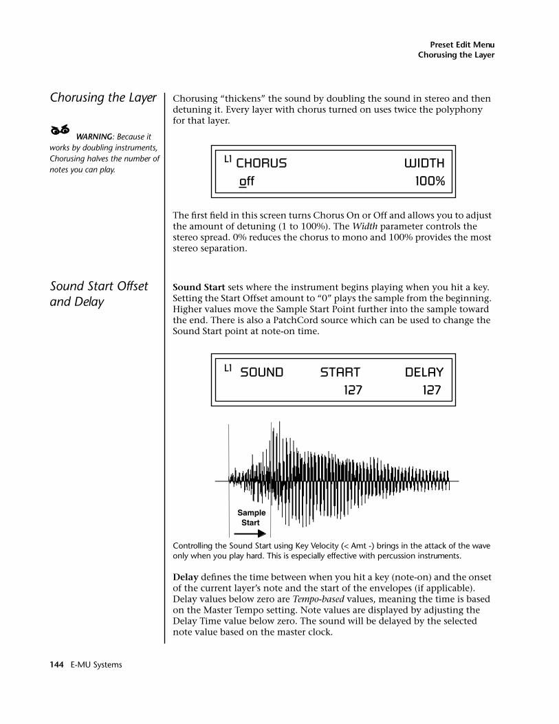
Preset Edit MenuChorusing the Layer
Chorusing the Layer Chorusing “thickens” the sound by doubling the sound in stereo and then detuning it. Every layer with chorus turned on uses twice the polyphony for that layer.
____ WARNING: Because it works by doubling instruments, Chorusing halves the number of notes you can play.
The first field in this screen turns Chorus On or Off and allows you to adjust the amount of detuning (1 to 100%). The Width parameter controls the stereo spread. 0% reduces the chorus to mono and 100% provides the most stereo separation.
Sound Start Offset and Delay
Sound Start sets where the instrument begins playing when you hit a key. Setting the Start Offset amount to “0” plays the sample from the beginning. Higher values move the Sample Start Point further into the sample toward the end. There is also a PatchCord source which can be used to change the Sound Start point at note-on time.
Controlling the Sound Start using Key Velocity (< Amt -) brings in the attack of the wave only when you play hard. This is especially effective with percussion instruments.
Delay defines the time between when you hit a key (note-on) and the onset of the current layer’s note and the start of the envelopes (if applicable). Delay values below zero are Tempo-based values, meaning the time is based on the Master Tempo setting. Note values are displayed by adjusting the Delay Time value below zero. The sound will be delayed by the selected note value based on the master clock.
L1 CHORUS WIDTH off 100%
L1 SOUND START DELAY 127 127
SampleStart
144 E-MU Systems
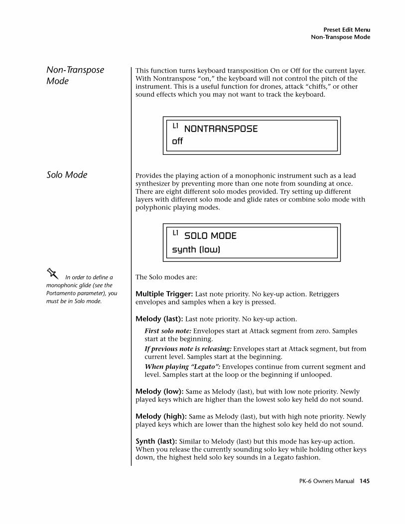
Preset Edit MenuNon-Transpose Mode
Non-Transpose Mode
This function turns keyboard transposition On or Off for the current layer. With Nontranspose “on,” the keyboard will not control the pitch of the instrument. This is a useful function for drones, attack “chiffs,” or other sound effects which you may not want to track the keyboard.
Solo Mode Provides the playing action of a monophonic instrument such as a lead synthesizer by preventing more than one note from sounding at once. There are eight different solo modes provided. Try setting up different layers with different solo mode and glide rates or combine solo mode with polyphonic playing modes.
OOOO In order to define a monophonic glide (see the Portamento parameter), you must be in Solo mode.
The Solo modes are:
Multiple Trigger: Last note priority. No key-up action. Retriggers envelopes and samples when a key is pressed.
Melody (last): Last note priority. No key-up action.
First solo note: Envelopes start at Attack segment from zero. Samples start at the beginning.
If previous note is releasing: Envelopes start at Attack segment, but from current level. Samples start at the beginning.
When playing “Legato”: Envelopes continue from current segment and level. Samples start at the loop or the beginning if unlooped.
Melody (low): Same as Melody (last), but with low note priority. Newly played keys which are higher than the lowest solo key held do not sound.
Melody (high): Same as Melody (last), but with high note priority. Newly played keys which are lower than the highest solo key held do not sound.
Synth (last): Similar to Melody (last) but this mode has key-up action. When you release the currently sounding solo key while holding other keys down, the highest held solo key sounds in a Legato fashion.
L1 NONTRANSPOSEoff
L1 SOLO MODEsynth (low)
PK-6 Owners Manual 145
Preset Edit MenuAssign Group
Synth (low): Same as Synth (last) but with low note priority. When you release the currently sounding solo key while holding other keys down, the lowest held solo key sounds in a Legato fashion (MiniMoog).
Synth (high): Same as Synth (last) but with high note priority. When you release the currently sounding solo key while holding other keys down, the highest held solo key sounds in a Legato fashion.
Fingered Glide: Same as Synth (last), except that Glide is disabled when playing Staccato, enabled when playing Legato.
Assign Group Use the Assign Group parameter to assign a certain number of channels to each layer. By assigning all voices in the preset to assign groups, important parts are protected from being “stolen” by more recently played keys. Or you can assign a voice, such as an open high hat, to a mono channel so it is cancelled by a closed high hat on the same mono channel. Layers rotate within their assigned “bin” of channels, not interfering with other bins.
The modes are:
Poly All: Notes are played polyphonically with dynamic channel assignment using all 64 channels.
Poly 16 A-B: Two bins of 16 channels each. Notes are played polyphoni-cally with dynamic channel assignment using no more than 16 channels.
Poly 8 A-D: Four bins of 8 channels each. Notes are played polyphonically with dynamic channel assignment using no more than 8 channels each.
Poly 4 A-D: Four bins of 4 channels each. Notes are played polyphonically with dynamic channel assignment using no more than 4 channels each.
Poly 2 A-D: Four bins of 2 channels each. Notes are played polyphonically with dynamic channel assignment using no more than 2 channels each.
Mono A-I: Nine monophonic channels. Any layers assigned to the same letter interrupt each other without affecting other layers.
L1 ASSIGN GROUPpoly all
146 E-MU Systems
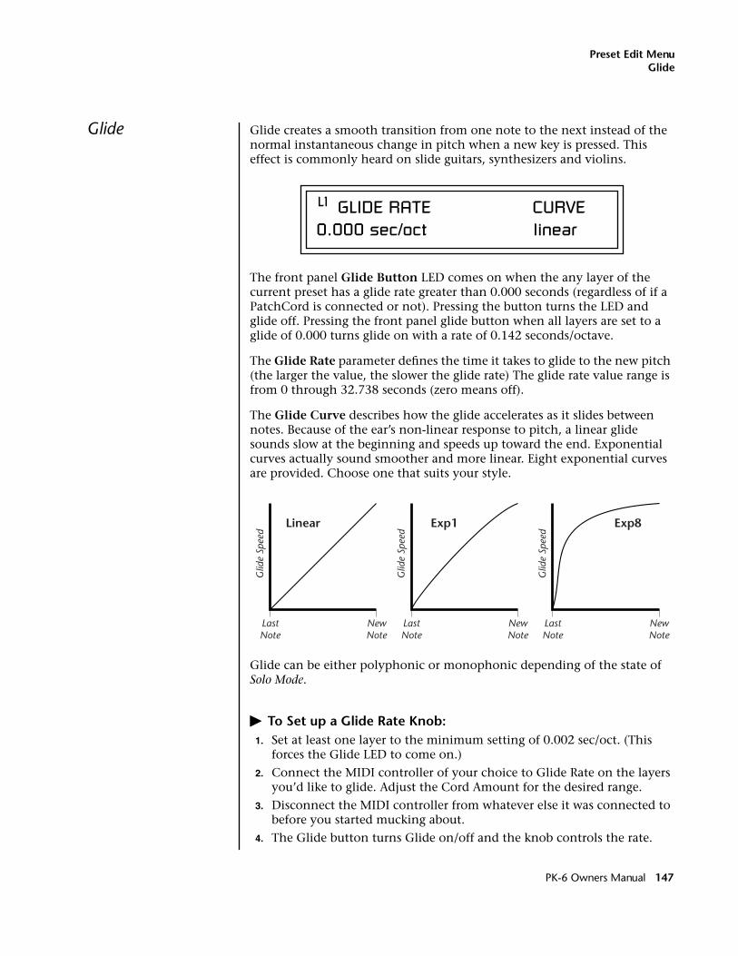
Preset Edit MenuGlide
Glide Glide creates a smooth transition from one note to the next instead of the normal instantaneous change in pitch when a new key is pressed. This effect is commonly heard on slide guitars, synthesizers and violins.
The front panel Glide Button LED comes on when the any layer of the current preset has a glide rate greater than 0.000 seconds (regardless of if a PatchCord is connected or not). Pressing the button turns the LED and glide off. Pressing the front panel glide button when all layers are set to a glide of 0.000 turns glide on with a rate of 0.142 seconds/octave.
The Glide Rate parameter defines the time it takes to glide to the new pitch (the larger the value, the slower the glide rate) The glide rate value range is from 0 through 32.738 seconds (zero means off).
The Glide Curve describes how the glide accelerates as it slides between notes. Because of the ear’s non-linear response to pitch, a linear glide sounds slow at the beginning and speeds up toward the end. Exponential curves actually sound smoother and more linear. Eight exponential curves are provided. Choose one that suits your style.
Glide can be either polyphonic or monophonic depending of the state of Solo Mode.
� To Set up a Glide Rate Knob:1. Set at least one layer to the minimum setting of 0.002 sec/oct. (This
forces the Glide LED to come on.)
2. Connect the MIDI controller of your choice to Glide Rate on the layers you’d like to glide. Adjust the Cord Amount for the desired range.
3. Disconnect the MIDI controller from whatever else it was connected to before you started mucking about.
4. The Glide button turns Glide on/off and the knob controls the rate.
L1 GLIDE RATE CURVE0.000 sec/oct linear
Glid
e Sp
eed
LastNote
NewNote
Linear
Glid
e Sp
eed
LastNote
NewNote
Exp1
Glid
e Sp
eed
LastNote
NewNote
Exp8
PK-6 Owners Manual 147
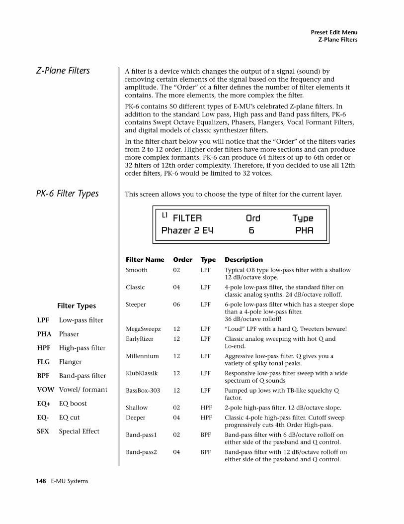
Preset Edit MenuZ-Plane Filters
Z-Plane Filters A filter is a device which changes the output of a signal (sound) by removing certain elements of the signal based on the frequency and amplitude. The “Order” of a filter defines the number of filter elements it contains. The more elements, the more complex the filter.
PK-6 contains 50 different types of E-MU’s celebrated Z-plane filters. In addition to the standard Low pass, High pass and Band pass filters, PK-6 contains Swept Octave Equalizers, Phasers, Flangers, Vocal Formant Filters, and digital models of classic synthesizer filters.
In the filter chart below you will notice that the “Order” of the filters varies from 2 to 12 order. Higher order filters have more sections and can produce more complex formants. PK-6 can produce 64 filters of up to 6th order or 32 filters of 12th order complexity. Therefore, if you decided to use all 12th order filters, PK-6 would be limited to 32 voices.
PK-6 Filter Types This screen allows you to choose the type of filter for the current layer.
Filter Name Order Type Description
Smooth 02 LPF Typical OB type low-pass filter with a shallow 12 dB/octave slope.
Classic 04 LPF 4-pole low-pass filter, the standard filter on classic analog synths. 24 dB/octave rolloff.
Steeper 06 LPF 6-pole low-pass filter which has a steeper slope than a 4-pole low-pass filter. 36 dB/octave rolloff!
MegaSweepz 12 LPF “Loud” LPF with a hard Q. Tweeters beware!
EarlyRizer 12 LPF Classic analog sweeping with hot Q and Lo-end.
Millennium 12 LPF Aggressive low-pass filter. Q gives you a variety of spiky tonal peaks.
KlubKlassik 12 LPF Responsive low-pass filter sweep with a wide spectrum of Q sounds
BassBox-303 12 LPF Pumped up lows with TB-like squelchy Q factor.
Shallow 02 HPF 2-pole high-pass filter. 12 dB/octave slope.
Deeper 04 HPF Classic 4-pole high-pass filter. Cutoff sweep progressively cuts 4th Order High-pass.
Band-pass1 02 BPF Band-pass filter with 6 dB/octave rolloff on either side of the passband and Q control.
Band-pass2 04 BPF Band-pass filter with 12 dB/octave rolloff on either side of the passband and Q control.
L1 FILTER Ord TypePhazer 2 E4 6 PHA
Filter Types
LPF Low-pass filter
PHA Phaser
HPF High-pass filter
FLG Flanger
BPF Band-pass filter
VOW Vowel/ formant
EQ+ EQ boost
EQ- EQ cut
SFX Special Effect
148 E-MU Systems
Preset Edit MenuPK-6 Filter Types
ContraBand 06 BPF A novel band-pass filter where the frequency peaks and dips midway in the frequency range.
Swept1>1oct 06 EQ+ Parametric filter with 24 dB of boost or cut and a one octave bandwidth.
Swept2>1oct 06 EQ+ Parametric filter with 24 dB of boost or cut. The bandwidth of the filter is two octaves wide at the low end of the audio spectrum, gradually changing to one octave wide at the upper end.
Swept3>1oct 06 EQ+ Parametric filter with 24 dB of boost or cut. The bandwidth of the filter is three octaves wide at the low end of the audio spectrum, gradually changing to one octave wide at the upper end.
DJAlkaline 12 EQ+ Band accentuating filter, Q shifts “ring” frequency.
AceOfBass 12 EQ+ Bass-boost to bass-cut morph
TB-OrNot-TB 12 EQ+ Great Bassline “Processor.”
BolandBass 12 EQ+ Constant bass boost with mid-tone Q control.
BassTracer 12 EQ+ Low Q boosts bass. Try sawtooth or square waveform with Q set to 115.
RogueHertz 12 EQ+ Bass with mid-range boost and smooth Q. Sweep cutoff with Q at 127.
RazorBlades 12 EQ- Cuts a series of frequency bands.Q selects different bands.
RadioCraze 12 EQ- Band limited for a cheap radio-like EQ
AahAyEeh 06 VOW Vowel formant filter which sweeps from “Ah” sound, through “Ay” sound to “Ee” sound at maximum frequency setting. Q varies the apparent size of the mouth cavity.
Ooh-To-Aah 06 VOW Vowel formant filter which sweeps from “Oo” sound, through “Oh” sound to “Ah” sound at maximum frequency setting. Q varies the apparent size of mouth cavity.
MultiQVox 12 VOW Multi-Formant, Map Q To velocity.
Ooh-To-Eee 12 VOW Oooh to Eeee formant morph.
TalkingHedz 12 VOW “Oui” morphing filter. Q adds peaks.
Eeh-To-Aah 12 VOW “E” to “Ah” formant movement. Q accentuates “peakiness.”
UbuOrator 12 VOW Aah-Uuh vowel with no Q. Raise Q for throaty vocals.
DeepBouche 12 VOW French vowels! “Ou-Est” vowel at low Q.
PhazeShift1 06 PHA Recreates a comb filter effect typical of phase shifters. Frequency moves position of notches. Q varies the depth of the notches.
Filter Name Order Type Description
PK-6 Owners Manual 149
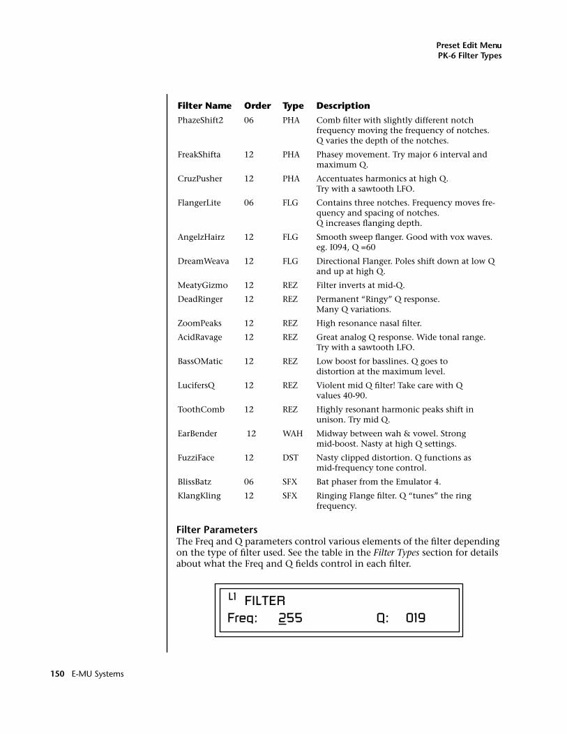
Preset Edit MenuPK-6 Filter Types
Filter ParametersThe Freq and Q parameters control various elements of the filter depending on the type of filter used. See the table in the Filter Types section for details about what the Freq and Q fields control in each filter.
PhazeShift2 06 PHA Comb filter with slightly different notch frequency moving the frequency of notches. Q varies the depth of the notches.
FreakShifta 12 PHA Phasey movement. Try major 6 interval and maximum Q.
CruzPusher 12 PHA Accentuates harmonics at high Q. Try with a sawtooth LFO.
FlangerLite 06 FLG Contains three notches. Frequency moves fre-quency and spacing of notches. Q increases flanging depth.
AngelzHairz 12 FLG Smooth sweep flanger. Good with vox waves. eg. I094, Q =60
DreamWeava 12 FLG Directional Flanger. Poles shift down at low Q and up at high Q.
MeatyGizmo 12 REZ Filter inverts at mid-Q.
DeadRinger 12 REZ Permanent “Ringy” Q response. Many Q variations.
ZoomPeaks 12 REZ High resonance nasal filter.
AcidRavage 12 REZ Great analog Q response. Wide tonal range. Try with a sawtooth LFO.
BassOMatic 12 REZ Low boost for basslines. Q goes to distortion at the maximum level.
LucifersQ 12 REZ Violent mid Q filter! Take care with Q values 40-90.
ToothComb 12 REZ Highly resonant harmonic peaks shift in unison. Try mid Q.
EarBender 12 WAH Midway between wah & vowel. Strong mid-boost. Nasty at high Q settings.
FuzziFace 12 DST Nasty clipped distortion. Q functions as mid-frequency tone control.
BlissBatz 06 SFX Bat phaser from the Emulator 4.
KlangKling 12 SFX Ringing Flange filter. Q “tunes” the ring frequency.
Filter Name Order Type Description
L1 FILTERFreq: 255 Q: 019
150 E-MU Systems
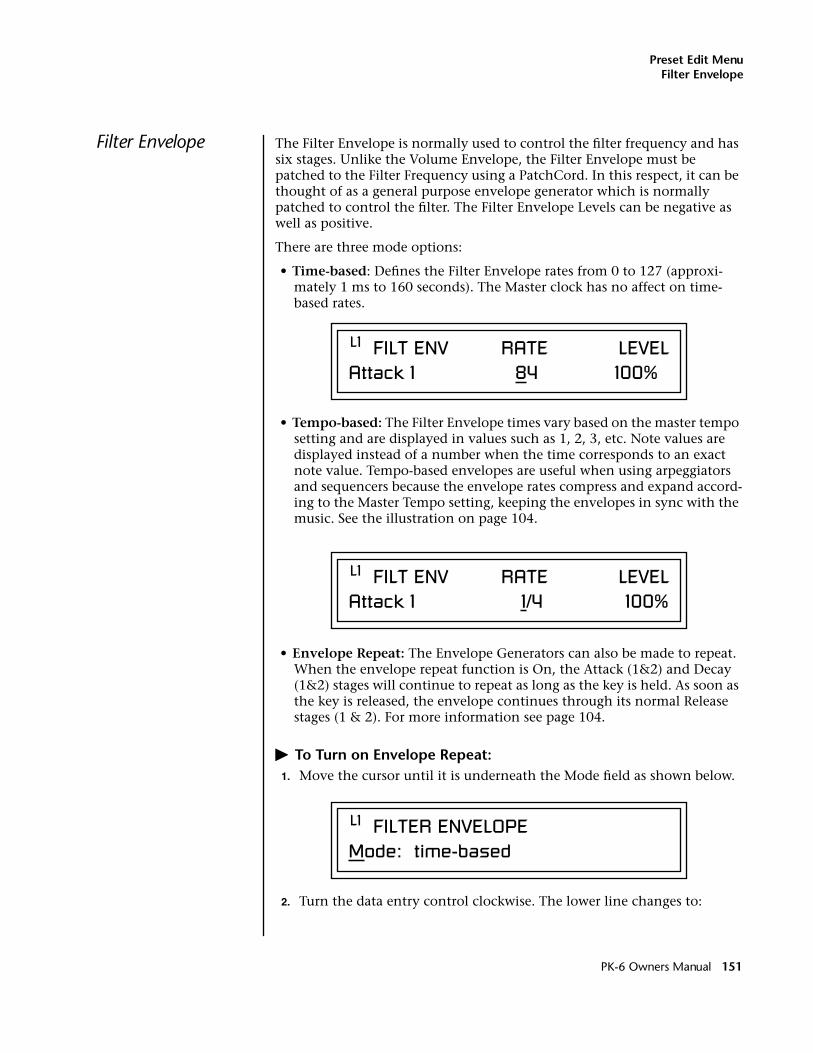
Preset Edit MenuFilter Envelope
Filter Envelope The Filter Envelope is normally used to control the filter frequency and has six stages. Unlike the Volume Envelope, the Filter Envelope must be patched to the Filter Frequency using a PatchCord. In this respect, it can be thought of as a general purpose envelope generator which is normally patched to control the filter. The Filter Envelope Levels can be negative as well as positive.
There are three mode options:
• Time-based: Defines the Filter Envelope rates from 0 to 127 (approxi-mately 1 ms to 160 seconds). The Master clock has no affect on time-based rates.
• Tempo-based: The Filter Envelope times vary based on the master tempo setting and are displayed in values such as 1, 2, 3, etc. Note values are displayed instead of a number when the time corresponds to an exact note value. Tempo-based envelopes are useful when using arpeggiators and sequencers because the envelope rates compress and expand accord-ing to the Master Tempo setting, keeping the envelopes in sync with the music. See the illustration on page 104.
• Envelope Repeat: The Envelope Generators can also be made to repeat. When the envelope repeat function is On, the Attack (1&2) and Decay (1&2) stages will continue to repeat as long as the key is held. As soon as the key is released, the envelope continues through its normal Release stages (1 & 2). For more information see page 104.
� To Turn on Envelope Repeat:1. Move the cursor until it is underneath the Mode field as shown below.
2. Turn the data entry control clockwise. The lower line changes to:
L1 FILT ENV RATE LEVELAttack 1 84 100%
L1 FILT ENV RATE LEVELAttack 1 1/4 100%
L1 FILTER ENVELOPEMode: time-based
PK-6 Owners Manual 151
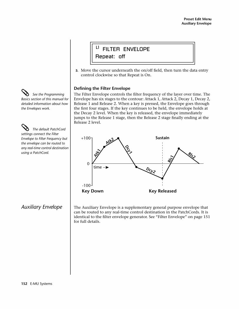
Preset Edit MenuAuxiliary Envelope
3. Move the cursor underneath the on/off field, then turn the data entry control clockwise so that Repeat is On.
Defining the Filter Envelope See the Programming Basics section of this manual for detailed information about how the Envelopes work.
The Filter Envelope controls the filter frequency of the layer over time. The Envelope has six stages to the contour: Attack 1, Attack 2, Decay 1, Decay 2, Release 1 and Release 2. When a key is pressed, the Envelope goes through the first four stages. If the key continues to be held, the envelope holds at the Decay 2 level. When the key is released, the envelope immediately jumps to the Release 1 stage, then the Release 2 stage finally ending at the Release 2 level.
The default PatchCord settings connect the Filter Envelope to Filter Frequency but the envelope can be routed to any real-time control destination using a PatchCord.
Auxiliary Envelope The Auxiliary Envelope is a supplementary general purpose envelope that can be routed to any real-time control destination in the PatchCords. It is identical to the filter envelope generator. See “Filter Envelope” on page 151 for full details.
L1 FILTER ENVELOPERepeat: off
Atk1
Atk2
Dcy1
Dcy2Rl
s1
Rls2
Key Down Key Released
Sustain
time0
+100
-100
152 E-MU Systems
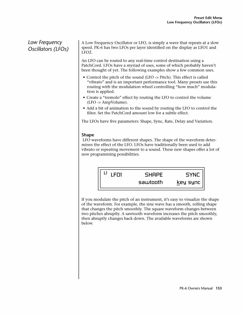
Preset Edit MenuLow Frequency Oscillators (LFOs)
Low Frequency Oscillators (LFOs)
A Low Frequency Oscillator or LFO, is simply a wave that repeats at a slow speed. PK-6 has two LFOs per layer identified on the display as LFO1 and LFO2.
An LFO can be routed to any real-time control destination using a PatchCord. LFOs have a myriad of uses, some of which probably haven’t been thought of yet. The following examples show a few common uses.
• Control the pitch of the sound (LFO -> Pitch). This effect is called “vibrato” and is an important performance tool. Many presets use this routing with the modulation wheel controlling “how much” modula-tion is applied.
• Create a “tremolo” effect by routing the LFO to control the volume (LFO -> AmpVolume).
• Add a bit of animation to the sound by routing the LFO to control the filter. Set the PatchCord amount low for a subtle effect.
The LFOs have five parameters: Shape, Sync, Rate, Delay and Variation.
Shape LFO waveforms have different shapes. The shape of the waveform deter-mines the effect of the LFO. LFOs have traditionally been used to add vibrato or repeating movement to a sound. These new shapes offer a lot of new programming possibilities.
If you modulate the pitch of an instrument, it’s easy to visualize the shape of the waveform. For example, the sine wave has a smooth, rolling shape that changes the pitch smoothly. The square waveform changes between two pitches abruptly. A sawtooth waveform increases the pitch smoothly, then abruptly changes back down. The available waveforms are shown below.
L1 LFO1 SHAPE SYNC sawtooth key sync
PK-6 Owners Manual 153
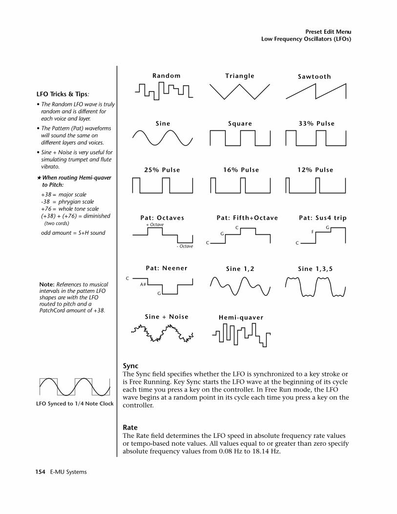
Preset Edit MenuLow Frequency Oscillators (LFOs)
SyncThe Sync field specifies whether the LFO is synchronized to a key stroke or is Free Running. Key Sync starts the LFO wave at the beginning of its cycle each time you press a key on the controller. In Free Run mode, the LFO wave begins at a random point in its cycle each time you press a key on the controller.
RateThe Rate field determines the LFO speed in absolute frequency rate values or tempo-based note values. All values equal to or greater than zero specify absolute frequency values from 0.08 Hz to 18.14 Hz.
LFO Tricks & Tips:
• The Random LFO wave is truly random and is different for each voice and layer.
• The Pattern (Pat) waveforms will sound the same on different layers and voices.
• Sine + Noise is very useful for simulating trumpet and flutevibrato.
�When routing Hemi-quaver to Pitch:
+38 = major scale-38 = phrygian scale+76 = whole tone scale(+38) + (+76) = diminished (two cords)
odd amount = S+H sound
Note: References to musical intervals in the pattern LFO shapes are with the LFO routed to pitch and a PatchCord amount of +38.
Triangle
Square
Sine 1,2 Sine 1,3,5
Sine
Sawtooth
25% Pulse
33% Pulse
12% Pulse16% Pulse
Random
Pat: Fifth+Octave
C
CG
Pat: Octaves+ Octave
- OctaveC
FG
Pat: Sus4 trip
C
G
A#
Pat: Neener
Hemi-quaver Sine + Noise
LFO Synced to 1/4 Note Clock
154 E-MU Systems
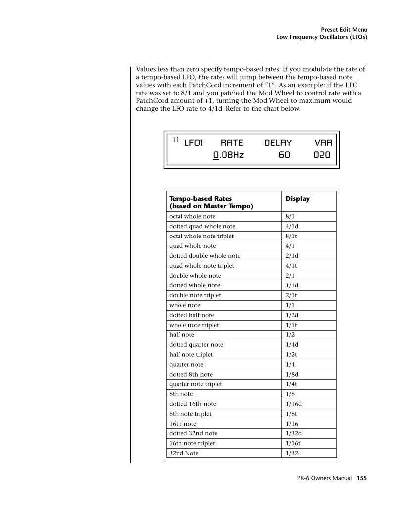
Preset Edit MenuLow Frequency Oscillators (LFOs)
Values less than zero specify tempo-based rates. If you modulate the rate of a tempo-based LFO, the rates will jump between the tempo-based note values with each PatchCord increment of “1”. As an example: if the LFO rate was set to 8/1 and you patched the Mod Wheel to control rate with a PatchCord amount of +1, turning the Mod Wheel to maximum would change the LFO rate to 4/1d. Refer to the chart below.
Tempo-based Rates (based on Master Tempo)
Display
octal whole note 8/1
dotted quad whole note 4/1d
octal whole note triplet 8/1t
quad whole note 4/1
dotted double whole note 2/1d
quad whole note triplet 4/1t
double whole note 2/1
dotted whole note 1/1d
double note triplet 2/1t
whole note 1/1
dotted half note 1/2d
whole note triplet 1/1t
half note 1/2
dotted quarter note 1/4d
half note triplet 1/2t
quarter note 1/4
dotted 8th note 1/8d
quarter note triplet 1/4t
8th note 1/8
dotted 16th note 1/16d
8th note triplet 1/8t
16th note 1/16
dotted 32nd note 1/32d
16th note triplet 1/16t
32nd Note 1/32
L1 LFO1 RATE DELAY VAR 0.08Hz 60 020
PK-6 Owners Manual 155
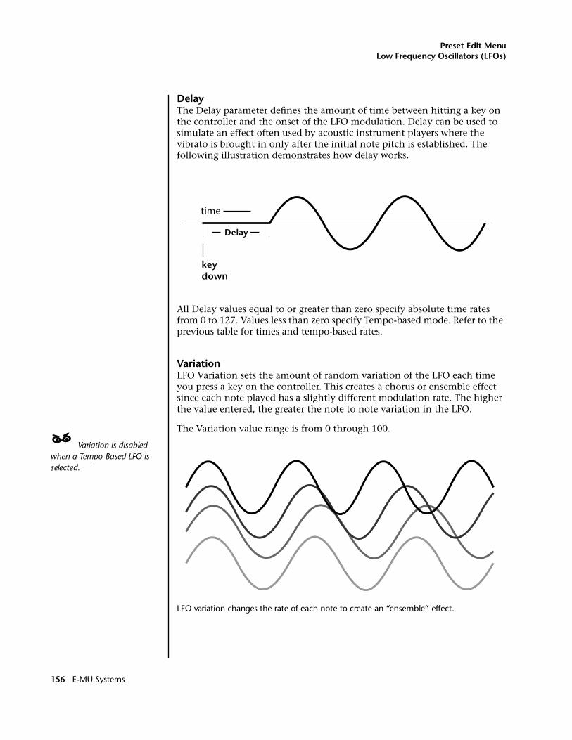
Preset Edit MenuLow Frequency Oscillators (LFOs)
DelayThe Delay parameter defines the amount of time between hitting a key on the controller and the onset of the LFO modulation. Delay can be used to simulate an effect often used by acoustic instrument players where the vibrato is brought in only after the initial note pitch is established. The following illustration demonstrates how delay works.
All Delay values equal to or greater than zero specify absolute time rates from 0 to 127. Values less than zero specify Tempo-based mode. Refer to the previous table for times and tempo-based rates.
VariationLFO Variation sets the amount of random variation of the LFO each time you press a key on the controller. This creates a chorus or ensemble effect since each note played has a slightly different modulation rate. The higher the value entered, the greater the note to note variation in the LFO.
The Variation value range is from 0 through 100.
____ Variation is disabled when a Tempo-Based LFO is selected.
LFO variation changes the rate of each note to create an “ensemble” effect.
time
keydown
Delay
156 E-MU Systems
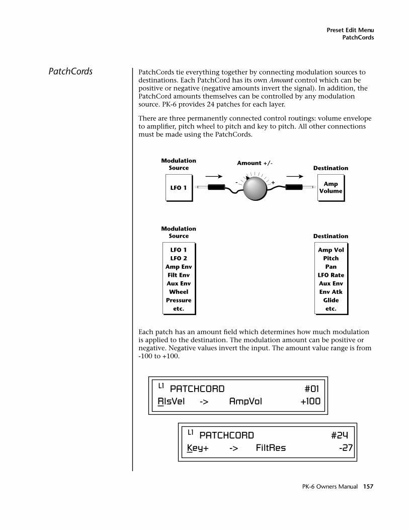
Preset Edit MenuPatchCords
PatchCords PatchCords tie everything together by connecting modulation sources to destinations. Each PatchCord has its own Amount control which can be positive or negative (negative amounts invert the signal). In addition, the PatchCord amounts themselves can be controlled by any modulation source. PK-6 provides 24 patches for each layer.
There are three permanently connected control routings: volume envelope to amplifier, pitch wheel to pitch and key to pitch. All other connections must be made using the PatchCords.
Each patch has an amount field which determines how much modulation is applied to the destination. The modulation amount can be positive or negative. Negative values invert the input. The amount value range is from -100 to +100.
ModulationSource
LFO 1
DestinationAmount +/-
AmpVolume
ModulationSource
LFO 1LFO 2
Amp EnvFilt EnvAux EnvWheel
Pressureetc.
Amp VolPitchPan
LFO RateAux EnvEnv Atk
Glideetc.
Destination
- +
L1 PATCHCORD #01RlsVel -> AmpVol +100
L1 PATCHCORD #24Key+ -> FiltRes -27
PK-6 Owners Manual 157
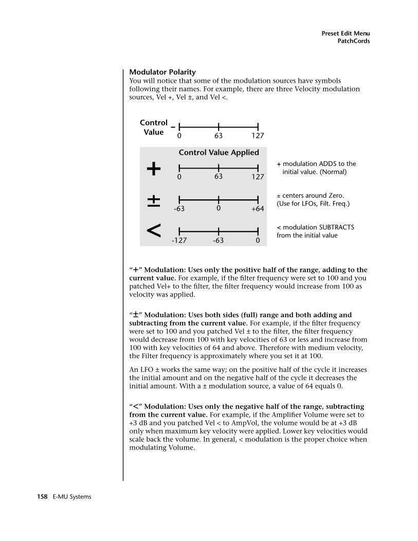
Preset Edit MenuPatchCords
Modulator PolarityYou will notice that some of the modulation sources have symbols following their names. For example, there are three Velocity modulation sources, Vel +, Vel ±, and Vel <.
“+” Modulation: Uses only the positive half of the range, adding to the current value. For example, if the filter frequency were set to 100 and you patched Vel+ to the filter, the filter frequency would increase from 100 as velocity was applied.
“±” Modulation: Uses both sides (full) range and both adding and subtracting from the current value. For example, if the filter frequency were set to 100 and you patched Vel ± to the filter, the filter frequency would decrease from 100 with key velocities of 63 or less and increase from 100 with key velocities of 64 and above. Therefore with medium velocity, the Filter frequency is approximately where you set it at 100.
An LFO ± works the same way; on the positive half of the cycle it increases the initial amount and on the negative half of the cycle it decreases the initial amount. With a ± modulation source, a value of 64 equals 0.
“<” Modulation: Uses only the negative half of the range, subtracting from the current value. For example, if the Amplifier Volume were set to +3 dB and you patched Vel < to AmpVol, the volume would be at +3 dB only when maximum key velocity were applied. Lower key velocities would scale back the volume. In general, < modulation is the proper choice when modulating Volume.
+ + modulation ADDS to the initial value. (Normal)
< modulation SUBTRACTSfrom the initial value
± centers around Zero.(Use for LFOs, Filt. Freq.)
ControlValue
Control Value Applied
0 12763
0 12763
-63 +640
-127 0-63
±<
158 E-MU Systems
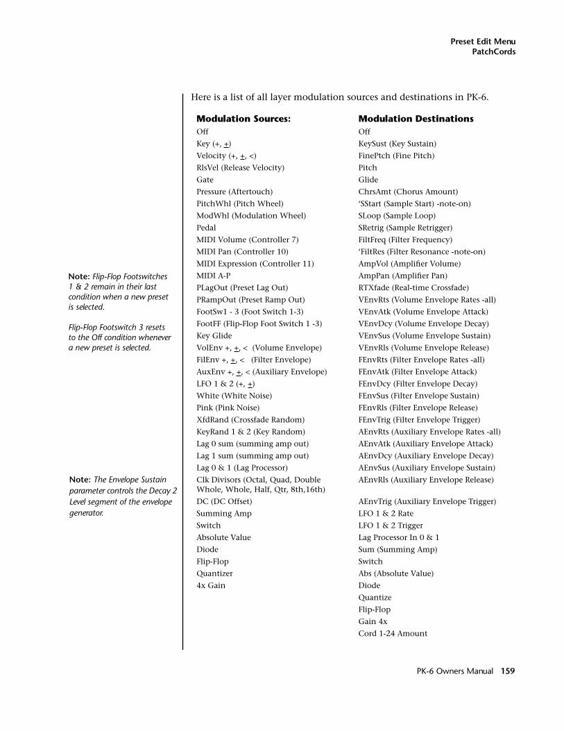
Preset Edit MenuPatchCords
Here is a list of all layer modulation sources and destinations in PK-6.
Modulation Sources: Modulation DestinationsOff Off
Key (+, +) KeySust (Key Sustain)
Velocity (+, +, <) FinePtch (Fine Pitch)
RlsVel (Release Velocity) Pitch
Gate Glide
Pressure (Aftertouch) ChrsAmt (Chorus Amount)
PitchWhl (Pitch Wheel) ‘SStart (Sample Start) -note-on)
ModWhl (Modulation Wheel) SLoop (Sample Loop)
Pedal SRetrig (Sample Retrigger)
MIDI Volume (Controller 7) FiltFreq (Filter Frequency)
MIDI Pan (Controller 10) ‘FiltRes (Filter Resonance -note-on)
MIDI Expression (Controller 11) AmpVol (Amplifier Volume)
MIDI A-P AmpPan (Amplifier Pan)
PLagOut (Preset Lag Out) RTXfade (Real-time Crossfade)
PRampOut (Preset Ramp Out) VEnvRts (Volume Envelope Rates -all)
FootSw1 - 3 (Foot Switch 1-3) VEnvAtk (Volume Envelope Attack)
FootFF (Flip-Flop Foot Switch 1 -3) VEnvDcy (Volume Envelope Decay)
Key Glide VEnvSus (Volume Envelope Sustain)
VolEnv +, +, < (Volume Envelope) VEnvRls (Volume Envelope Release)
FilEnv +, +, < (Filter Envelope) FEnvRts (Filter Envelope Rates -all)
AuxEnv +, +, < (Auxiliary Envelope) FEnvAtk (Filter Envelope Attack)
LFO 1 & 2 (+, +) FEnvDcy (Filter Envelope Decay)
White (White Noise) FEnvSus (Filter Envelope Sustain)
Pink (Pink Noise) FEnvRls (Filter Envelope Release)
XfdRand (Crossfade Random) FEnvTrig (Filter Envelope Trigger)
KeyRand 1 & 2 (Key Random) AEnvRts (Auxiliary Envelope Rates -all)
Lag 0 sum (summing amp out) AEnvAtk (Auxiliary Envelope Attack)
Lag 1 sum (summing amp out) AEnvDcy (Auxiliary Envelope Decay)
Lag 0 & 1 (Lag Processor) AEnvSus (Auxiliary Envelope Sustain)
Clk Divisors (Octal, Quad, Double Whole, Whole, Half, Qtr, 8th,16th)
AEnvRls (Auxiliary Envelope Release)
DC (DC Offset) AEnvTrig (Auxiliary Envelope Trigger)
Summing Amp LFO 1 & 2 Rate
Switch LFO 1 & 2 Trigger
Absolute Value Lag Processor In 0 & 1
Diode Sum (Summing Amp)
Flip-Flop Switch
Quantizer Abs (Absolute Value)
4x Gain Diode
Quantize
Flip-Flop
Gain 4x
Cord 1-24 Amount
Note: Flip-Flop Footswitches 1 & 2 remain in their last condition when a new preset is selected.
Flip-Flop Footswitch 3 resets to the Off condition whenever a new preset is selected.
Note: The Envelope Sustain parameter controls the Decay 2 Level segment of the envelope generator.
PK-6 Owners Manual 159
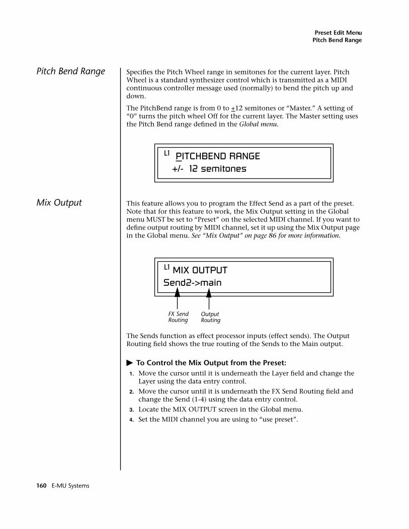
Preset Edit MenuPitch Bend Range
Pitch Bend Range Specifies the Pitch Wheel range in semitones for the current layer. Pitch Wheel is a standard synthesizer control which is transmitted as a MIDI continuous controller message used (normally) to bend the pitch up and down.
The PitchBend range is from 0 to +12 semitones or “Master.” A setting of “0” turns the pitch wheel Off for the current layer. The Master setting uses the Pitch Bend range defined in the Global menu.
Mix Output This feature allows you to program the Effect Send as a part of the preset. Note that for this feature to work, the Mix Output setting in the Global menu MUST be set to “Preset” on the selected MIDI channel. If you want to define output routing by MIDI channel, set it up using the Mix Output page in the Global menu. See “Mix Output” on page 86 for more information.
The Sends function as effect processor inputs (effect sends). The Output Routing field shows the true routing of the Sends to the Main output.
� To Control the Mix Output from the Preset:1. Move the cursor until it is underneath the Layer field and change the
Layer using the data entry control.
2. Move the cursor until it is underneath the FX Send Routing field and change the Send (1-4) using the data entry control.
3. Locate the MIX OUTPUT screen in the Global menu.
4. Set the MIDI channel you are using to “use preset”.
L1 PITCHBEND RANGE +/- 12 semitones
L1 MIX OUTPUTSend2->main
OutputRouting
FX SendRouting
160 E-MU Systems
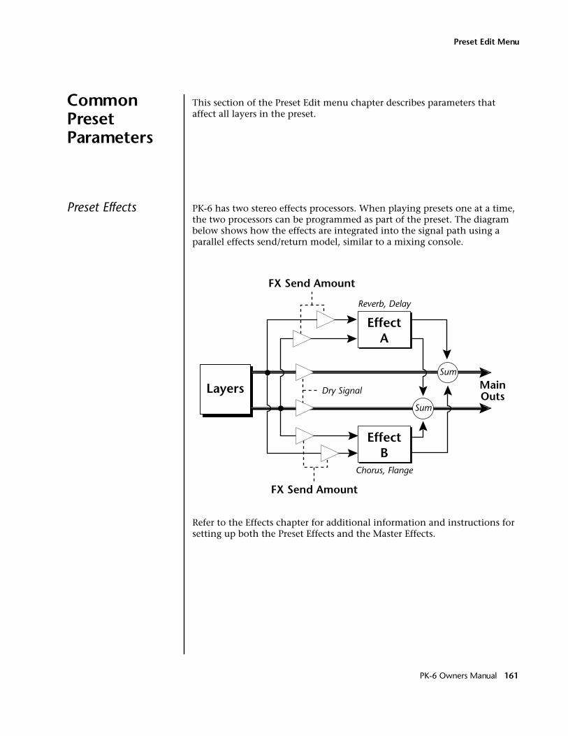
Preset Edit Menu
Common PresetParameters
This section of the Preset Edit menu chapter describes parameters that affect all layers in the preset.
Preset Effects PK-6 has two stereo effects processors. When playing presets one at a time, the two processors can be programmed as part of the preset. The diagram below shows how the effects are integrated into the signal path using a parallel effects send/return model, similar to a mixing console.
Refer to the Effects chapter for additional information and instructions for setting up both the Preset Effects and the Master Effects.
EffectA
Sum
Sum
MainOuts
EffectB
FX Send Amount
FX Send Amount
Layers
Reverb, Delay
Chorus, Flange
Dry Signal
PK-6 Owners Manual 161
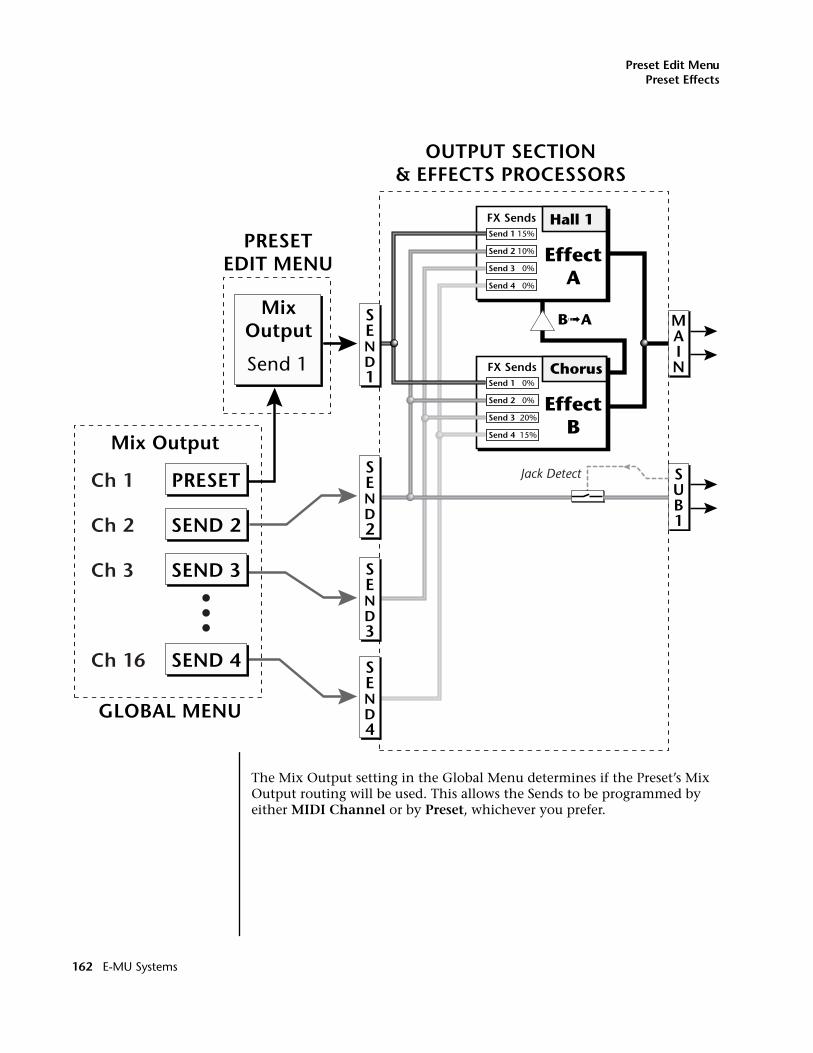
Preset Edit MenuPreset Effects
The Mix Output setting in the Global Menu determines if the Preset’s Mix Output routing will be used. This allows the Sends to be programmed by either MIDI Channel or by Preset, whichever you prefer.
SUB1
MAIN
OUTPUT SECTION& EFFECTS PROCESSORS
FX Sends Hall 1
EffectA
FX Sends Chorus
EffectB
B➟A
Jack DetectPRESET
MixOutput
Mix Output
Send 1
Send 1 15%
Send 2 10%
Send 3 0%
Send 4 0%
Send 1 0%
Send 2 0%
Send 3 20%
Send 4 15%
GLOBAL MENU
PRESETEDIT MENU
Ch 1
SEND 2Ch 2
SEND 3Ch 3
SEND 4Ch 16
SEND1
SEND2
SEND3
SEND4
162 E-MU Systems
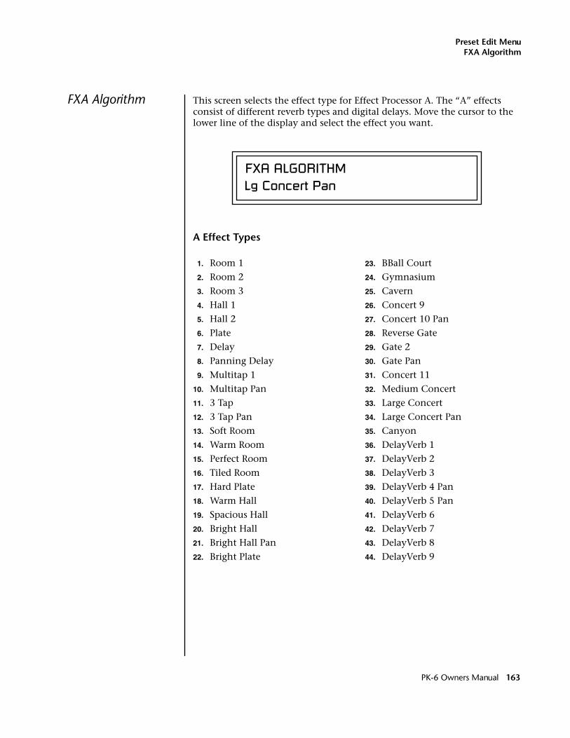
Preset Edit MenuFXA Algorithm
FXA Algorithm This screen selects the effect type for Effect Processor A. The “A” effects consist of different reverb types and digital delays. Move the cursor to the lower line of the display and select the effect you want.
A Effect Types
FXA ALGORITHMLg Concert Pan
1. Room 1
2. Room 2
3. Room 3
4. Hall 1
5. Hall 2
6. Plate
7. Delay
8. Panning Delay
9. Multitap 1
10. Multitap Pan
11. 3 Tap
12. 3 Tap Pan
13. Soft Room
14. Warm Room
15. Perfect Room
16. Tiled Room
17. Hard Plate
18. Warm Hall
19. Spacious Hall
20. Bright Hall
21. Bright Hall Pan
22. Bright Plate
23. BBall Court
24. Gymnasium
25. Cavern
26. Concert 9
27. Concert 10 Pan
28. Reverse Gate
29. Gate 2
30. Gate Pan
31. Concert 11
32. Medium Concert
33. Large Concert
34. Large Concert Pan
35. Canyon
36. DelayVerb 1
37. DelayVerb 2
38. DelayVerb 3
39. DelayVerb 4 Pan
40. DelayVerb 5 Pan
41. DelayVerb 6
42. DelayVerb 7
43. DelayVerb 8
44. DelayVerb 9
PK-6 Owners Manual 163
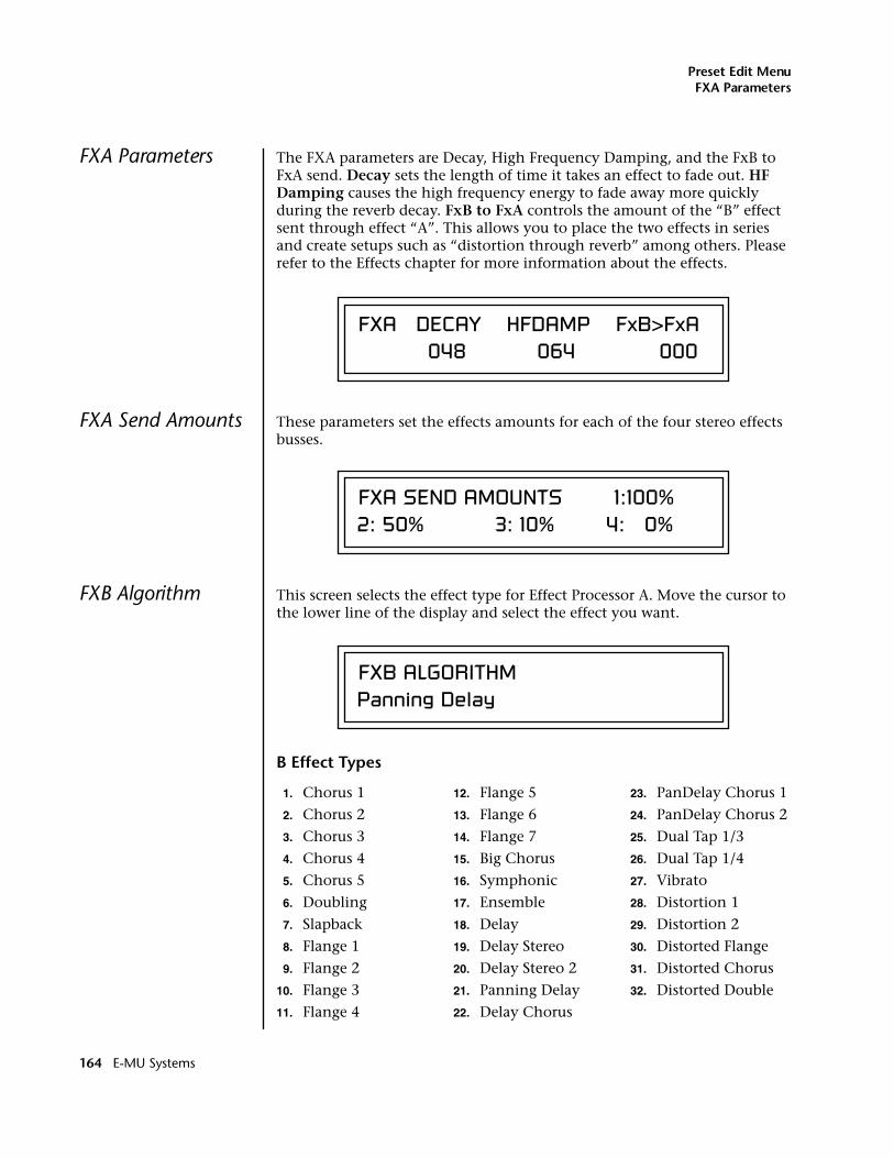
Preset Edit MenuFXA Parameters
FXA Parameters The FXA parameters are Decay, High Frequency Damping, and the FxB to FxA send. Decay sets the length of time it takes an effect to fade out. HF Damping causes the high frequency energy to fade away more quickly during the reverb decay. FxB to FxA controls the amount of the “B” effect sent through effect “A”. This allows you to place the two effects in series and create setups such as “distortion through reverb” among others. Please refer to the Effects chapter for more information about the effects.
FXA Send Amounts These parameters set the effects amounts for each of the four stereo effects busses.
FXB Algorithm This screen selects the effect type for Effect Processor A. Move the cursor to the lower line of the display and select the effect you want.
B Effect Types
FXA DECAY HFDAMP FxB>FxA 048 064 000
FXA SEND AMOUNTS 1:100% 2: 50% 3: 10% 4: 0%
FXB ALGORITHMPanning Delay
1. Chorus 1
2. Chorus 2
3. Chorus 3
4. Chorus 4
5. Chorus 5
6. Doubling
7. Slapback
8. Flange 1
9. Flange 2
10. Flange 3
11. Flange 4
12. Flange 5
13. Flange 6
14. Flange 7
15. Big Chorus
16. Symphonic
17. Ensemble
18. Delay
19. Delay Stereo
20. Delay Stereo 2
21. Panning Delay
22. Delay Chorus
23. PanDelay Chorus 1
24. PanDelay Chorus 2
25. Dual Tap 1/3
26. Dual Tap 1/4
27. Vibrato
28. Distortion 1
29. Distortion 2
30. Distorted Flange
31. Distorted Chorus
32. Distorted Double
164 E-MU Systems
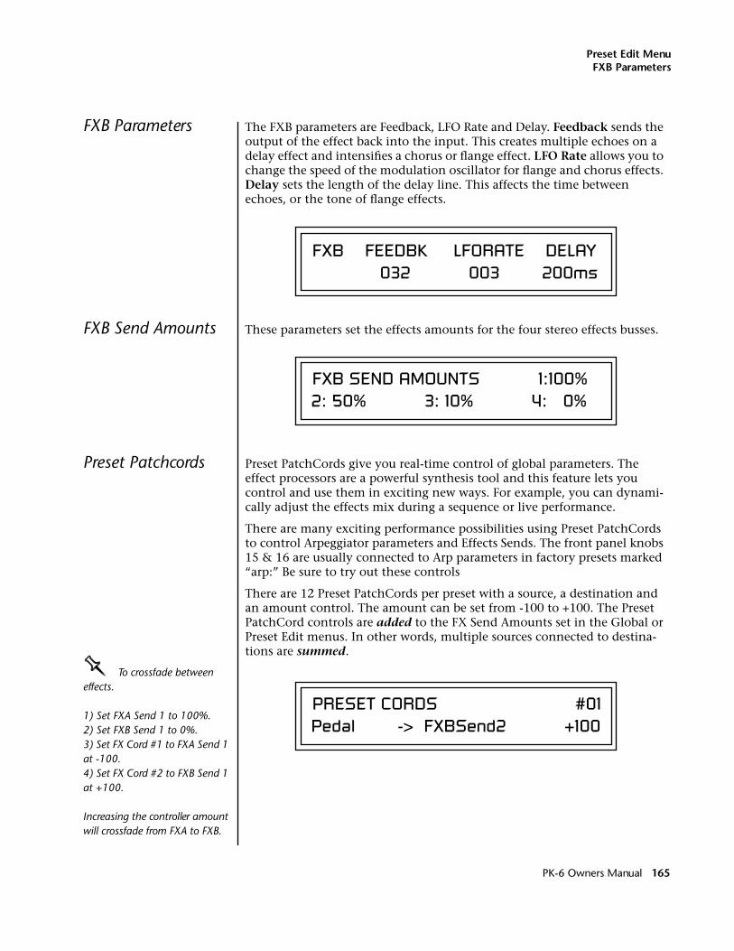
Preset Edit MenuFXB Parameters
FXB Parameters The FXB parameters are Feedback, LFO Rate and Delay. Feedback sends the output of the effect back into the input. This creates multiple echoes on a delay effect and intensifies a chorus or flange effect. LFO Rate allows you to change the speed of the modulation oscillator for flange and chorus effects. Delay sets the length of the delay line. This affects the time between echoes, or the tone of flange effects.
FXB Send Amounts These parameters set the effects amounts for the four stereo effects busses.
Preset Patchcords Preset PatchCords give you real-time control of global parameters. The effect processors are a powerful synthesis tool and this feature lets you control and use them in exciting new ways. For example, you can dynami-cally adjust the effects mix during a sequence or live performance.
There are many exciting performance possibilities using Preset PatchCords to control Arpeggiator parameters and Effects Sends. The front panel knobs 15 & 16 are usually connected to Arp parameters in factory presets marked “arp:” Be sure to try out these controls
There are 12 Preset PatchCords per preset with a source, a destination and an amount control. The amount can be set from -100 to +100. The Preset PatchCord controls are added to the FX Send Amounts set in the Global or Preset Edit menus. In other words, multiple sources connected to destina-tions are summed.
OOOO To crossfade between effects.
1) Set FXA Send 1 to 100%.2) Set FXB Send 1 to 0%.3) Set FX Cord #1 to FXA Send 1 at -100.4) Set FX Cord #2 to FXB Send 1 at +100.
Increasing the controller amount will crossfade from FXA to FXB.
FXB FEEDBK LFORATE DELAY 032 003 200ms
FXB SEND AMOUNTS 1:100% 2: 50% 3: 10% 4: 0%
PRESET CORDS #01Pedal -> FXBSend2 +100
PK-6 Owners Manual 165
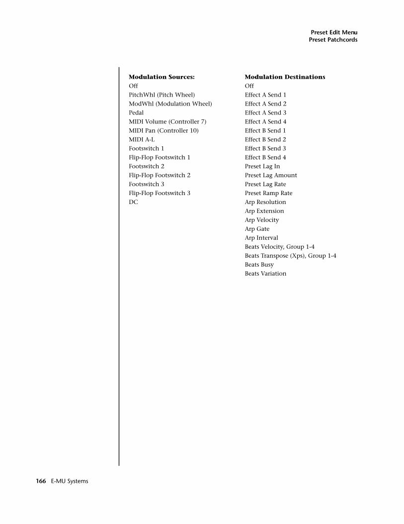
Preset Edit MenuPreset Patchcords
Modulation Sources: Modulation DestinationsOff Off
PitchWhl (Pitch Wheel) Effect A Send 1
ModWhl (Modulation Wheel) Effect A Send 2
Pedal Effect A Send 3
MIDI Volume (Controller 7) Effect A Send 4
MIDI Pan (Controller 10) Effect B Send 1
MIDI A-L Effect B Send 2
Footswitch 1 Effect B Send 3
Flip-Flop Footswitch 1 Effect B Send 4
Footswitch 2 Preset Lag In
Flip-Flop Footswitch 2 Preset Lag Amount
Footswitch 3 Preset Lag Rate
Flip-Flop Footswitch 3 Preset Ramp Rate
DC Arp Resolution
Arp Extension
Arp Velocity
Arp Gate
Arp Interval
Beats Velocity, Group 1-4
Beats Transpose (Xps), Group 1-4
Beats Busy
Beats Variation
166 E-MU Systems
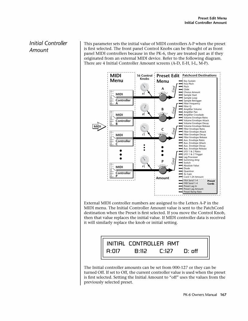
Preset Edit MenuInitial Controller Amount
Initial Controller Amount
This parameter sets the initial value of MIDI controllers A-P when the preset is first selected. The front panel Control Knobs can be thought of as front panel MIDI controllers because in the PK-6, they are treated just as if they originated from an external MIDI device. Refer to the following diagram. There are 4 Initial Controller Amount screens (A-D, E-H, I-L, M-P).
External MIDI controller numbers are assigned to the Letters A-P in the MIDI menu. The Initial Controller Amount value is sent to the PatchCord destination when the Preset is first selected. If you move the Control Knob, then that value replaces the initial value. If MIDI controller data is received it will similarly replace the knob or initial setting.
The Initial controller amounts can be set from 000-127 or they can be turned Off. If set to Off, the current controller value is used when the preset is first selected. Setting the Initial Amount to “off” uses the values from the previously selected preset.
Patchcord Destinations16 ControlKnobs
+-
MIDIMenu
Preset EditMenu
A
B
C
P
MIDI
Amount
+-
+-
+-
A
B
C
P
Cor
dC
ord
Cor
dC
ord
Key SustainFine PitchPitchGlideChorus AmountSample StartSample LoopSample RetriggerFilter FrequencyFilter QAmplifier VolumeAmplifier PanAmplifier CrossfadeVolume Envelope RatesVolume Envelope AttackVolume Envelope DecayVolume Envelope ReleaseFilter Envelope RatesFilter Envelope AttackFilter Envelope DecayFilter Envelope ReleaseAux. Envelope RatesAux. Envelope AttackAux. Envelope DecayAux. Envelope ReleaseLFO 1 & 2 RatesLFO 1 & 2 TriggerLag ProcessorSumming AmpSwitchAbsolute ValueDiodeQuantizer4x GainCord 1-24 Amount
FXA Send 1-4 FXB Send 1-4Preset Lag InPreset Lag AmountPreset Ramp Rate
PresetCords
012 MIDI
ControllerA
31
95
64
012 MIDI
ControllerP
31
95
64
012 MIDI
ControllerC
31
95
64
012 MIDI
ControllerB
31
95
64
INITIAL CONTROLLER AMTA:017 B:112 C:127 D: off
PK-6 Owners Manual 167
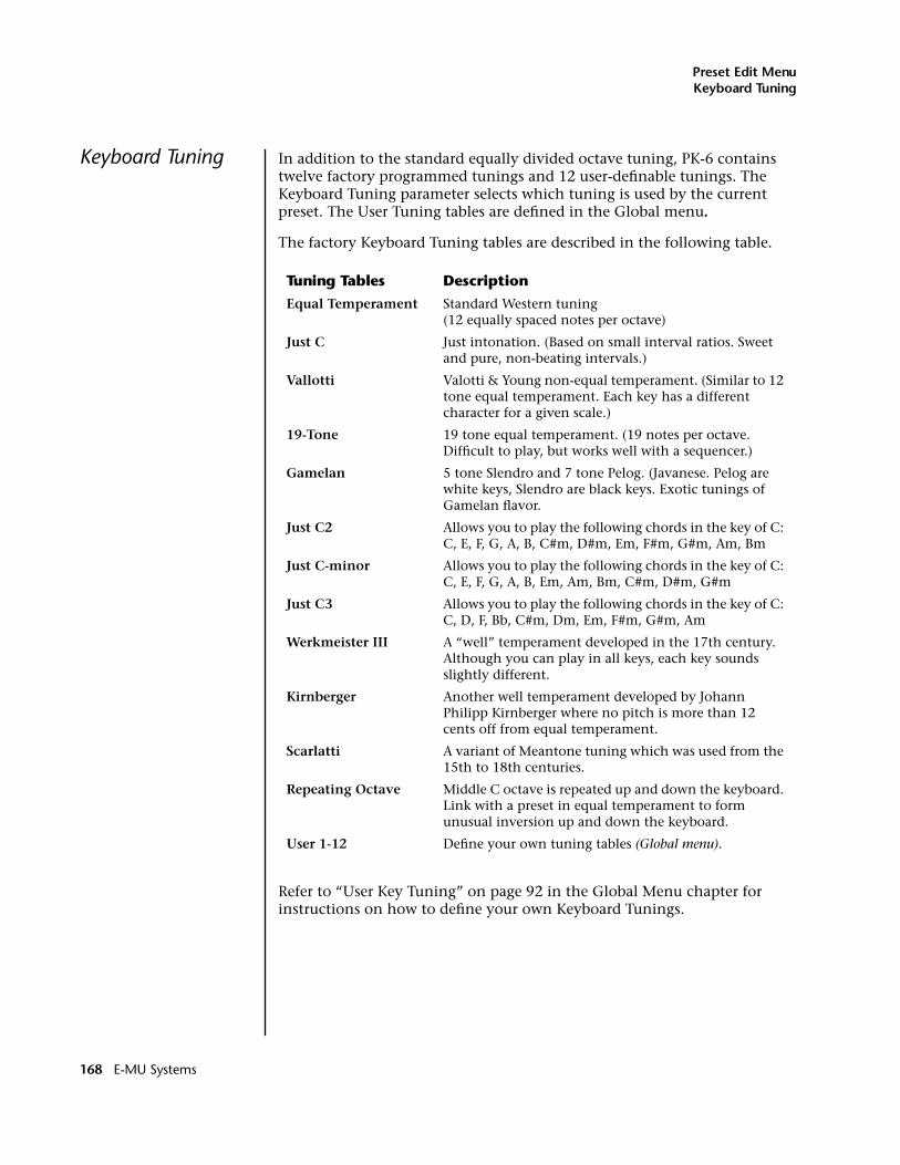
Preset Edit MenuKeyboard Tuning
Keyboard Tuning In addition to the standard equally divided octave tuning, PK-6 contains twelve factory programmed tunings and 12 user-definable tunings. The Keyboard Tuning parameter selects which tuning is used by the current preset. The User Tuning tables are defined in the Global menu.
The factory Keyboard Tuning tables are described in the following table.
Refer to “User Key Tuning” on page 92 in the Global Menu chapter for instructions on how to define your own Keyboard Tunings.
Tuning Tables Description
Equal Temperament Standard Western tuning (12 equally spaced notes per octave)
Just C Just intonation. (Based on small interval ratios. Sweet and pure, non-beating intervals.)
Vallotti Valotti & Young non-equal temperament. (Similar to 12 tone equal temperament. Each key has a different character for a given scale.)
19-Tone 19 tone equal temperament. (19 notes per octave. Difficult to play, but works well with a sequencer.)
Gamelan 5 tone Slendro and 7 tone Pelog. (Javanese. Pelog are white keys, Slendro are black keys. Exotic tunings of Gamelan flavor.
Just C2 Allows you to play the following chords in the key of C: C, E, F, G, A, B, C#m, D#m, Em, F#m, G#m, Am, Bm
Just C-minor Allows you to play the following chords in the key of C: C, E, F, G, A, B, Em, Am, Bm, C#m, D#m, G#m
Just C3 Allows you to play the following chords in the key of C: C, D, F, Bb, C#m, Dm, Em, F#m, G#m, Am
Werkmeister III A “well” temperament developed in the 17th century. Although you can play in all keys, each key sounds slightly different.
Kirnberger Another well temperament developed by Johann Philipp Kirnberger where no pitch is more than 12 cents off from equal temperament.
Scarlatti A variant of Meantone tuning which was used from the 15th to 18th centuries.
Repeating Octave Middle C octave is repeated up and down the keyboard. Link with a preset in equal temperament to form unusual inversion up and down the keyboard.
User 1-12 Define your own tuning tables (Global menu).
168 E-MU Systems
Preset Edit MenuKeyboard Tuning
The Just C Tuning TablesWell Tempered and Just were standard keyboard tunings up until the 20th-century when the current “equal tempered” scale became prevalent. In an equal tempered scale, the octave is equally divided into 12 parts. In Just or Well Tempered scales, the 12 notes are separately tuned to produce pure chords. However, in Just tunings you are limited to playing certain chords and if you play the wrong chord it may sound very BAD!
PK-6 implements the MIDI Tuning Dump protocol which allows you to create tuning tables on your personal computer and download them via MIDI. There are several computer applications available on the internet which let you create and download tuning tables via MIDI.
PK-6 allows you to modulate between keys by providing you 12 user tuning tables. Tuning tables can be changed as you play using a program change (create several presets with the same sound and different tuning tables), by MIDI SysEx command (using a programmable MIDI footswitch or other device), or using a continuous controller (link 2 presets and crossfade between them using a controller).
The Just C2, Just C min, Just C3 Tuning TablesThese new tuning tables take the concept of just intonation a step beyond previous E-MU products. Fully explaining the mysteries of just intonation is beyond the scope of this manual, but the subject is covered exhaustively in Hermann Helmholtz’s On the Sensations of Tone, available at most libraries and bookstores.
The new tables are called Just C2, Just C3, and Just C Minor. Try playing in the key of C/Cm using each table. You’ll quickly discover both the wonders and the frustrations of just intonation! In Just C, for example, you’ll find that the chords C, Em, F, G, and Am sound beautiful. If you hold one of these chords, you’ll hear no “beating”. After playing for a few minutes, switch back to Equal Temperament for a rude awakening!
At this point you might wonder why anyone would use Equal Temper-ament to begin with. For the answer to that question, play a D, Dmi, or Bb chord!.The intervallic ratios that make the C & G chords sound so pure make the D chord sound horribly out of tune. That's why we had to include Just C3. In this tuning, D, Dmi and Bb sound in tune, but the G chord will sound wrong.
Each of the 4 tables allows you to play a different group of common chords in just intonation. Sadly, there is no single 12 note tuning that will allow all of the common chords to be in tune, and of course that's why they invented the equal temperament tuning system that we use today.
Just CPlay these chords: C, E, F, G, A, Cm, C#m, Em, F#m, Gm, Am
Just C2Play these chords: C, E, F, G, A, B, C#m, D#m, Em, G#m, Am, Bm
Just C2 minorPlay these chords: C, Db, D, Eb, G, Ab, Cm, Em, Fm, Gm
Just C3Play these chords: C, D, F, Bb, C#m, Dm, Em, F#m, G#m, Am
PK-6 Owners Manual 169
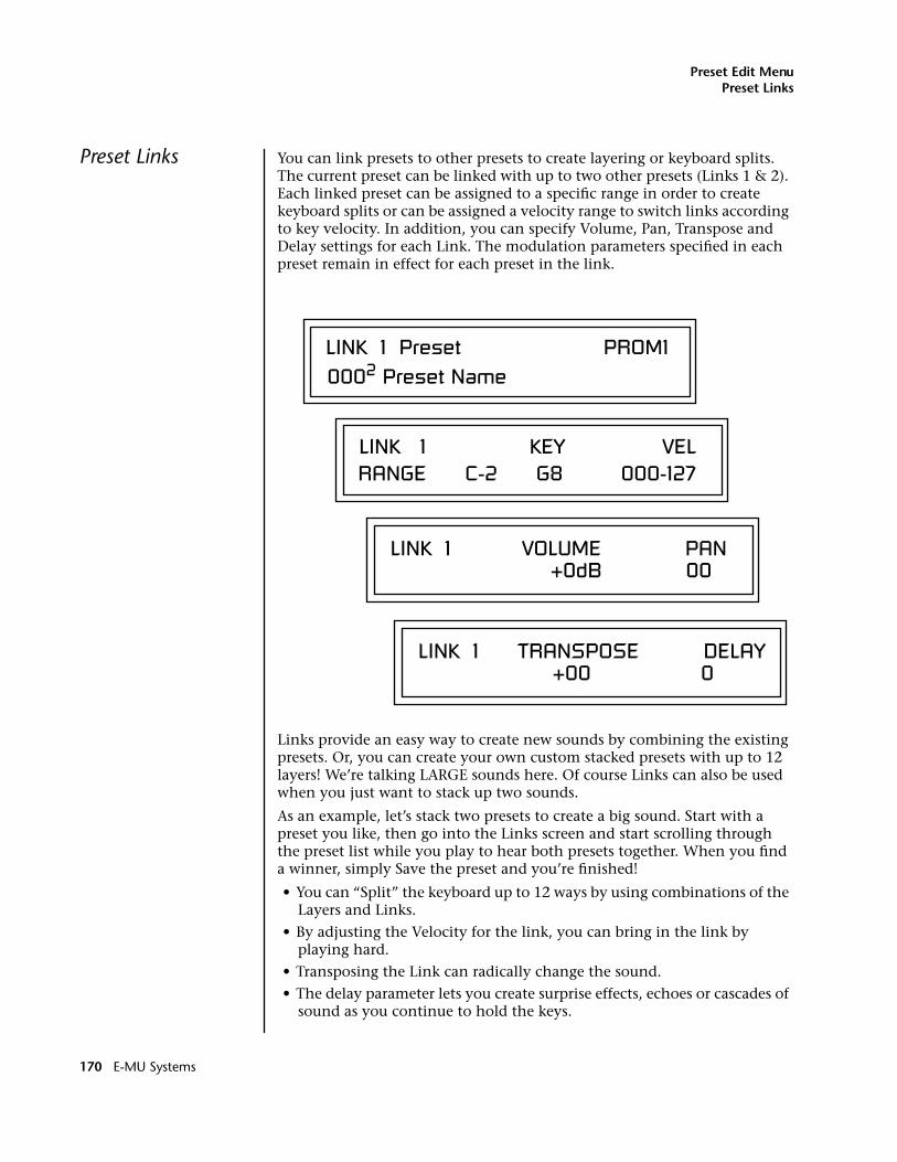
Preset Edit MenuPreset Links
Preset Links You can link presets to other presets to create layering or keyboard splits. The current preset can be linked with up to two other presets (Links 1 & 2). Each linked preset can be assigned to a specific range in order to create keyboard splits or can be assigned a velocity range to switch links according to key velocity. In addition, you can specify Volume, Pan, Transpose and Delay settings for each Link. The modulation parameters specified in each preset remain in effect for each preset in the link.
Links provide an easy way to create new sounds by combining the existing presets. Or, you can create your own custom stacked presets with up to 12 layers! We’re talking LARGE sounds here. Of course Links can also be used when you just want to stack up two sounds.
As an example, let’s stack two presets to create a big sound. Start with a preset you like, then go into the Links screen and start scrolling through the preset list while you play to hear both presets together. When you find a winner, simply Save the preset and you’re finished!
• You can “Split” the keyboard up to 12 ways by using combinations of the Layers and Links.
• By adjusting the Velocity for the link, you can bring in the link by playing hard.
• Transposing the Link can radically change the sound.
• The delay parameter lets you create surprise effects, echoes or cascades of sound as you continue to hold the keys.
LINK 1 Preset PROM10002 Preset Name
LINK 1 KEY VELRANGE C-2 G8 000-127
LINK 1 VOLUME PAN +0dB 00
LINK 1 TRANSPOSE DELAY +00 0
170 E-MU Systems
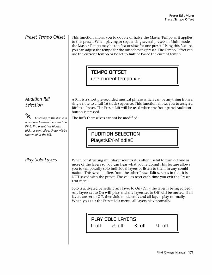
Preset Edit MenuPreset Tempo Offset
Preset Tempo Offset This function allows you to double or halve the Master Tempo as it applies to this preset. When playing or sequencing several presets in Multi mode, the Master Tempo may be too fast or slow for one preset. Using this feature, you can adjust the tempo for the misbehaving preset. The Tempo Offset can use the current tempo or be set to half or twice the current tempo.
Audition Riff Selection
A Riff is a short pre-recorded musical phrase which can be anything from a single note to a full 16-track sequence. This function allows you to assign a Riff to a Preset. The Preset Riff will be used when the front panel Audition button is pressed.
OOOO Listening to the Riffs is a quick way to learn the sounds in PK-6. If a preset has hidden tricks or controllers, these will be shown off in the Riff.
The Riffs themselves cannot be modified.
Play Solo Layers When constructing multilayer sounds it is often useful to turn off one or more of the layers so you can hear what you’re doing! This feature allows you to temporarily solo individual layers or listen to them in any combi-nation. This screen differs from the other Preset Edit screens in that it is NOT saved with the preset. The values reset each time you exit the Preset Edit menu.
Solo is activated by setting any layer to On (On = the layer is being Soloed). Any layers set to On will play and any layers set to Off will be muted. If all layers are set to Off, then Solo mode ends and all layers play normally. When you exit the Preset Edit menu, all layers play normally.
TEMPO OFFSETuse current tempo x 2
AUDITION SELECTIONPlays:KEY-MiddleC
PLAY SOLO LAYERS1: off 2: off 3: off 4: off
PK-6 Owners Manual 171
Preset Edit MenuPlay Solo Layers
172 E-MU Systems
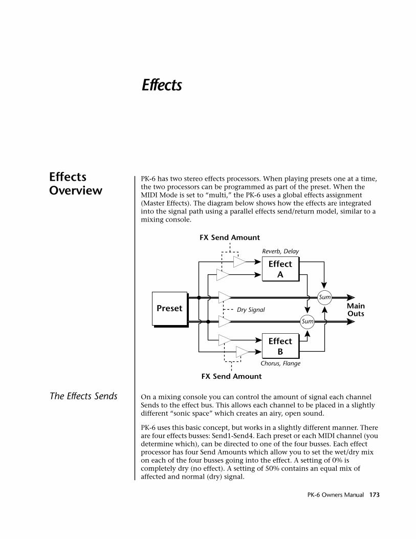
Effects
Effects Overview
PK-6 has two stereo effects processors. When playing presets one at a time, the two processors can be programmed as part of the preset. When the MIDI Mode is set to “multi,” the PK-6 uses a global effects assignment (Master Effects). The diagram below shows how the effects are integrated into the signal path using a parallel effects send/return model, similar to a mixing console.
The Effects Sends On a mixing console you can control the amount of signal each channel Sends to the effect bus. This allows each channel to be placed in a slightly different “sonic space” which creates an airy, open sound.
PK-6 uses this basic concept, but works in a slightly different manner. There are four effects busses: Send1-Send4. Each preset or each MIDI channel (you determine which), can be directed to one of the four busses. Each effect processor has four Send Amounts which allow you to set the wet/dry mix on each of the four busses going into the effect. A setting of 0% is completely dry (no effect). A setting of 50% contains an equal mix of affected and normal (dry) signal.
EffectA
Sum
Sum
MainOuts
EffectB
FX Send Amount
FX Send Amount
Preset
Reverb, Delay
Chorus, Flange
Dry Signal
PK-6 Owners Manual 173
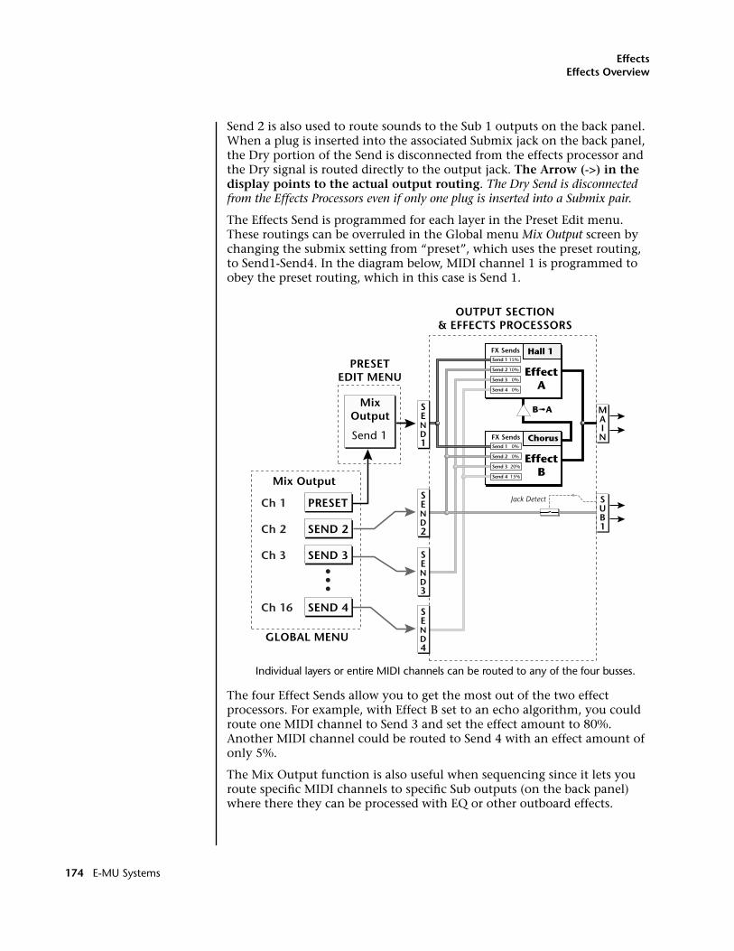
EffectsEffects Overview
Send 2 is also used to route sounds to the Sub 1 outputs on the back panel. When a plug is inserted into the associated Submix jack on the back panel, the Dry portion of the Send is disconnected from the effects processor and the Dry signal is routed directly to the output jack. The Arrow (->) in the display points to the actual output routing. The Dry Send is disconnected from the Effects Processors even if only one plug is inserted into a Submix pair.
The Effects Send is programmed for each layer in the Preset Edit menu. These routings can be overruled in the Global menu Mix Output screen by changing the submix setting from “preset”, which uses the preset routing, to Send1-Send4. In the diagram below, MIDI channel 1 is programmed to obey the preset routing, which in this case is Send 1.
Individual layers or entire MIDI channels can be routed to any of the four busses.
The four Effect Sends allow you to get the most out of the two effect processors. For example, with Effect B set to an echo algorithm, you could route one MIDI channel to Send 3 and set the effect amount to 80%. Another MIDI channel could be routed to Send 4 with an effect amount of only 5%.
The Mix Output function is also useful when sequencing since it lets you route specific MIDI channels to specific Sub outputs (on the back panel) where there they can be processed with EQ or other outboard effects.
SUB1
MAIN
OUTPUT SECTION& EFFECTS PROCESSORS
FX Sends Hall 1
EffectA
FX Sends Chorus
EffectB
B➟A
Jack DetectPRESET
MixOutput
Mix Output
Send 1
Send 1 15%
Send 2 10%
Send 3 0%
Send 4 0%
Send 1 0%
Send 2 0%
Send 3 20%
Send 4 15%
GLOBAL MENU
PRESETEDIT MENU
Ch 1
SEND 2Ch 2
SEND 3Ch 3
SEND 4Ch 16
SEND1
SEND2
SEND3
SEND4
174 E-MU Systems
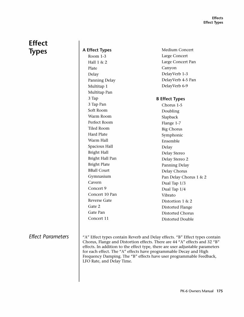
EffectsEffect Types
Effect Types
Effect Parameters “A” Effect types contain Reverb and Delay effects. “B” Effect types contain Chorus, Flange and Distortion effects. There are 44 “A” effects and 32 “B” effects. In addition to the effect type, there are user adjustable parameters for each effect. The “A” effects have programmable Decay and High Frequency Damping. The “B” effects have user programmable Feedback, LFO Rate, and Delay Time.
A Effect TypesRoom 1-3
Hall 1 & 2
Plate
Delay
Panning Delay
Multitap 1
Multitap Pan
3 Tap
3 Tap Pan
Soft Room
Warm Room
Perfect Room
Tiled Room
Hard Plate
Warm Hall
Spacious Hall
Bright Hall
Bright Hall Pan
Bright Plate
BBall Court
Gymnasium
Cavern
Concert 9
Concert 10 Pan
Reverse Gate
Gate 2
Gate Pan
Concert 11
Medium Concert
Large Concert
Large Concert Pan
Canyon
DelayVerb 1-3
DelayVerb 4-5 Pan
DelayVerb 6-9
B Effect TypesChorus 1-5
Doubling
Slapback
Flange 1-7
Big Chorus
Symphonic
Ensemble
Delay
Delay Stereo
Delay Stereo 2
Panning Delay
Delay Chorus
Pan Delay Chorus 1 & 2
Dual Tap 1/3
Dual Tap 1/4
Vibrato
Distortion 1 & 2
Distorted Flange
Distorted Chorus
Distorted Double
PK-6 Owners Manual 175
EffectsEffect Types
DecayThe Decay parameter is used when setting “A” type effects. Decay sets the length of time it takes an effect to fade out. When setting up reverb effects, Decay controls the room size and the reflectivity of the room. For larger room sizes and greater reflectivity, set the Decay value higher. When setting up delay effects, the Decay parameter controls how many echoes are produced or how long the echoes last. The greater the value, the more echoes and longer lengths of time. The Decay value range is from 0 through 90.
High Frequency DampingThe HF Damping parameter is used when setting “A” type effects. High Frequency energy tends to fade away first as a sound is dissipated in a room. the HF Damping parameter adjusts the amount of damping applied to the signal’s high frequency elements which, in turn, changes the characteristics of the room. Rooms with smooth, hard surfaces are more reflective and have less high frequency damping. Rooms filled with sound absorbing materials, such as curtains or people, have more high frequency damping. The value range for High Frequency Damping is from 0 through 127.
FeedbackThe Feedback parameter is used when setting “B” type effects. The Chorus and Flange effects have a controllable feedback loop after the delay element. Feeding back a small amount of the signal intensifies the effect by creating multiple cancellations or images. Higher feedback values increase the amount of the Feedback loop. The Feedback value range is from 0 to 127.
LFO RateThe LFO Rate parameter is used when setting “B” type effects. Both Chorus and Flange effects use a Low Frequency Oscillator (LFO) to animate the effect. LFO applied to a chorus effect creates the slight changes necessary for a realistic choral effect. Applied to a flanger effect, the LFO moves the comb filter notches and adds animation to the sound. The LFO Rate value range is from 0 to 127.
DelayFlanging, chorus and echoes are all based on a delay line where the signal is delayed by some time period and then mixed back with the unaltered signal. This parameter specifies the how much time passes before you hear the delayed signal. On some effects, this value cannot be changed. In this case, the field contains a dash. The Delay value range is from 0ms to 635ms.
Synchronize the delay time to the master clock by setting the delay time below zero. The delay time can be set to any of the standard clock divisors (listed on page 60) in order to lock the echos to the beat of the song.
176 E-MU Systems
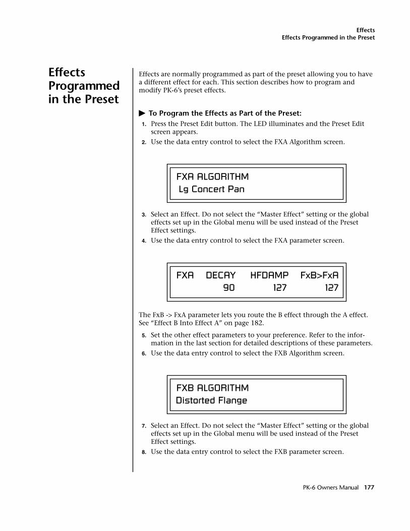
EffectsEffects Programmed in the Preset
Effects Programmed in the Preset
Effects are normally programmed as part of the preset allowing you to have a different effect for each. This section describes how to program and modify PK-6’s preset effects.
� To Program the Effects as Part of the Preset:1. Press the Preset Edit button. The LED illuminates and the Preset Edit
screen appears.
2. Use the data entry control to select the FXA Algorithm screen.
3. Select an Effect. Do not select the “Master Effect” setting or the global effects set up in the Global menu will be used instead of the Preset Effect settings.
4. Use the data entry control to select the FXA parameter screen.
The FxB -> FxA parameter lets you route the B effect through the A effect. See “Effect B Into Effect A” on page 182.
5. Set the other effect parameters to your preference. Refer to the infor-mation in the last section for detailed descriptions of these parameters.
6. Use the data entry control to select the FXB Algorithm screen.
7. Select an Effect. Do not select the “Master Effect” setting or the global effects set up in the Global menu will be used instead of the Preset Effect settings.
8. Use the data entry control to select the FXB parameter screen.
FXA ALGORITHM Lg Concert Pan
FXA DECAY HFDAMP FxB>FxA 90 127 127
FXB ALGORITHMDistorted Flange
PK-6 Owners Manual 177
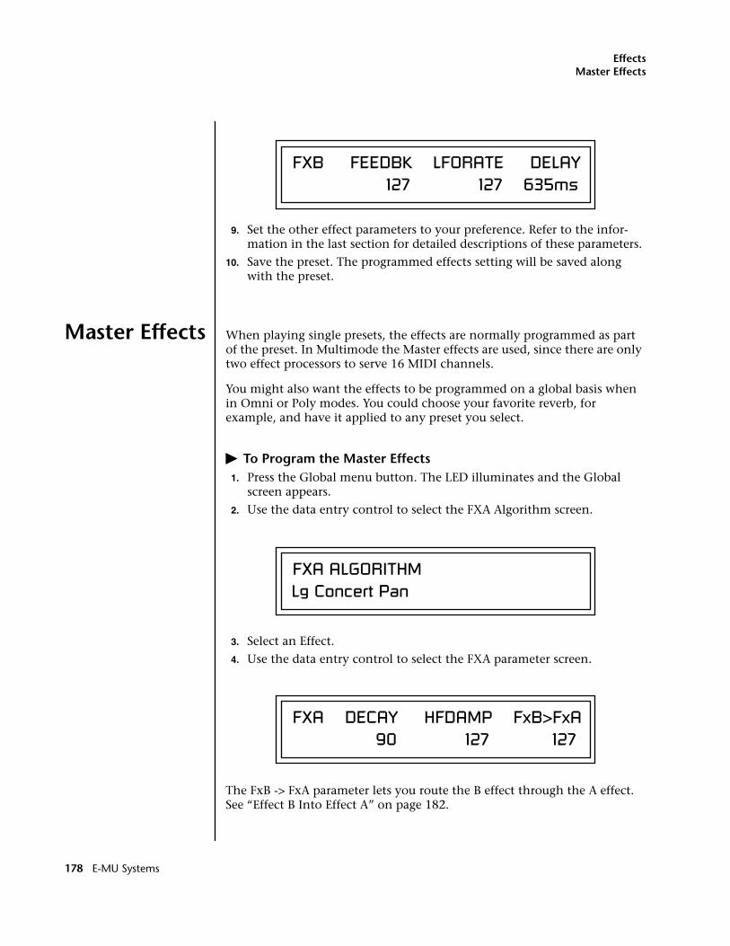
EffectsMaster Effects
9. Set the other effect parameters to your preference. Refer to the infor-mation in the last section for detailed descriptions of these parameters.
10. Save the preset. The programmed effects setting will be saved along with the preset.
Master Effects When playing single presets, the effects are normally programmed as part of the preset. In Multimode the Master effects are used, since there are only two effect processors to serve 16 MIDI channels.
You might also want the effects to be programmed on a global basis when in Omni or Poly modes. You could choose your favorite reverb, for example, and have it applied to any preset you select.
� To Program the Master Effects 1. Press the Global menu button. The LED illuminates and the Global
screen appears.
2. Use the data entry control to select the FXA Algorithm screen.
3. Select an Effect.
4. Use the data entry control to select the FXA parameter screen.
The FxB -> FxA parameter lets you route the B effect through the A effect. See “Effect B Into Effect A” on page 182.
FXB FEEDBK LFORATE DELAY 127 127 635ms
FXA ALGORITHMLg Concert Pan
FXA DECAY HFDAMP FxB>FxA 90 127 127
178 E-MU Systems
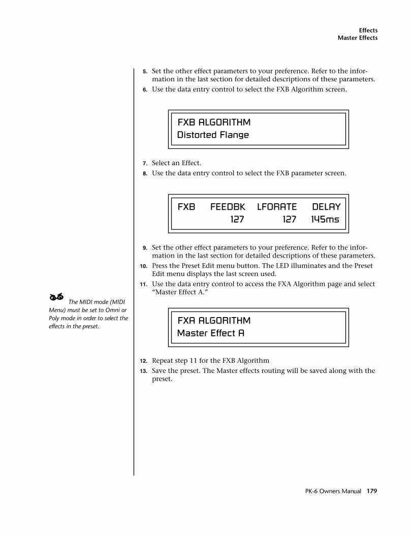
EffectsMaster Effects
5. Set the other effect parameters to your preference. Refer to the infor-mation in the last section for detailed descriptions of these parameters.
6. Use the data entry control to select the FXB Algorithm screen.
7. Select an Effect.
8. Use the data entry control to select the FXB parameter screen.
9. Set the other effect parameters to your preference. Refer to the infor-mation in the last section for detailed descriptions of these parameters.
10. Press the Preset Edit menu button. The LED illuminates and the Preset Edit menu displays the last screen used.
11. Use the data entry control to access the FXA Algorithm page and select “Master Effect A.”
____ The MIDI mode (MIDI Menu) must be set to Omni or Poly mode in order to select the effects in the preset.
12. Repeat step 11 for the FXB Algorithm
13. Save the preset. The Master effects routing will be saved along with the preset.
FXB ALGORITHMDistorted Flange
FXB FEEDBK LFORATE DELAY 127 127 145ms
FXA ALGORITHMMaster Effect A
PK-6 Owners Manual 179
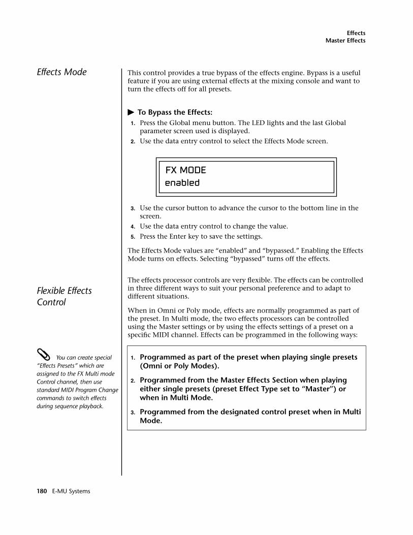
EffectsMaster Effects
Effects Mode This control provides a true bypass of the effects engine. Bypass is a useful feature if you are using external effects at the mixing console and want to turn the effects off for all presets.
� To Bypass the Effects:1. Press the Global menu button. The LED lights and the last Global
parameter screen used is displayed.
2. Use the data entry control to select the Effects Mode screen.
3. Use the cursor button to advance the cursor to the bottom line in the screen.
4. Use the data entry control to change the value.
5. Press the Enter key to save the settings.
The Effects Mode values are “enabled” and “bypassed.” Enabling the Effects Mode turns on effects. Selecting “bypassed” turns off the effects.
Flexible Effects Control
The effects processor controls are very flexible. The effects can be controlled in three different ways to suit your personal preference and to adapt to different situations.
When in Omni or Poly mode, effects are normally programmed as part of the preset. In Multi mode, the two effects processors can be controlled using the Master settings or by using the effects settings of a preset on a specific MIDI channel. Effects can be programmed in the following ways:
You can create special “Effects Presets” which are assigned to the FX Multi mode Control channel, then use standard MIDI Program Change commands to switch effects during sequence playback.
1. Programmed as part of the preset when playing single presets (Omni or Poly Modes).
2. Programmed from the Master Effects Section when playing either single presets (preset Effect Type set to “Master”) or when in Multi Mode.
3. Programmed from the designated control preset when in Multi Mode.
FX MODEenabled
180 E-MU Systems
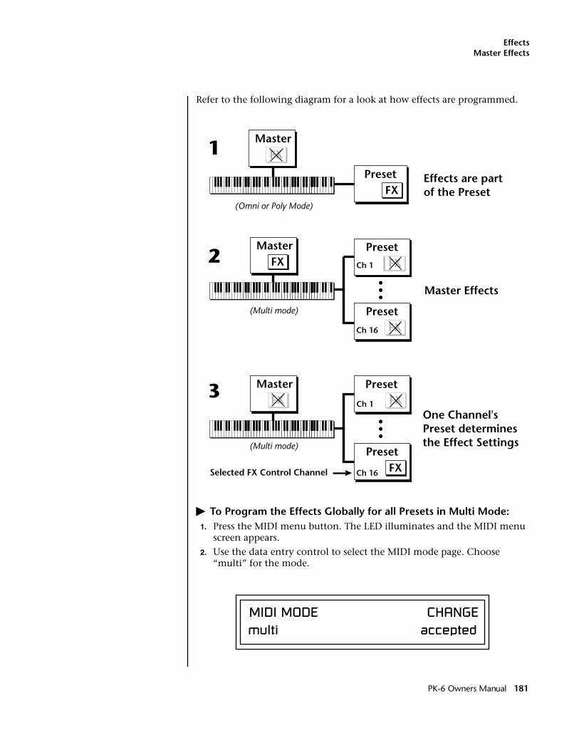
EffectsMaster Effects
Refer to the following diagram for a look at how effects are programmed.
� To Program the Effects Globally for all Presets in Multi Mode:1. Press the MIDI menu button. The LED illuminates and the MIDI menu
screen appears.
2. Use the data entry control to select the MIDI mode page. Choose “multi” for the mode.
PresetFX
MasterFX
Effects are partof the Preset
1
(Omni or Poly Mode)
MasterFX
Preset
Ch 16
Master Effects
PresetFXCh 1
2
(Multi mode)
PresetFX
Preset
FX
FX
Master
Ch 16
Ch 1
Selected FX Control Channel
One Channel'sPreset determinesthe Effect Settings
3
(Multi mode)
FX
MIDI MODE CHANGEmulti accepted
PK-6 Owners Manual 181
EffectsMaster Effects
3. Move the cursor to the Multi mode Effects Control page using the data entry control.
4. Set the Effect Control channel to use master settings using the data entry control.
5. Press the Enter key to save the settings and return to the main screen.
Using the Effects Channel Settings in Multi ModeIn Multi mode, the two effects processors can be controlled from the Master Effects settings or they can follow the effects settings of the preset on a special MIDI channel. The effect settings on this special channel will be applied to all the other MIDI channels. This allows the effects to be changed during a sequence simply by changing the preset on a specified MIDI channel.
� To Program the Effects by Channel Number in Multi Mode:1. Press the MIDI menu button. The LED illuminates and the MIDI menu
screen appears.
2. Use the data entry control to select the MIDI mode page. Choose “multi” for the mode.
3. Move the cursor to the Multi mode Effects Control field using the data entry control
4. Set the Effect Control to “preset on Channel #” (where # is replaced by the actual channel number from 1 through 16) using the data entry control.
5. Press Enter to save the settings and return to the main screen.
Effect B Into Effect A The output of effects processor B can be routed into effects processor A. This connects the effects in series instead of their normal parallel configu-ration. Two effects connected in series sound very different than the same two effects in parallel. For example, a chorus patched through reverb can turn a bland string section into a lush wall of sound. The B –>A amount can also be controlled for even more flexibility.
� To Send the Output of Effect B through Effect A:In this example, 100% of Effect B will be sent into Effect A.
1. Access the FXA parameter screen (in either the Global or Preset Edit menus) that contains the FXB –>FXA parameter.
FX MULTIMODE CONTROLuse master settings
182 E-MU Systems
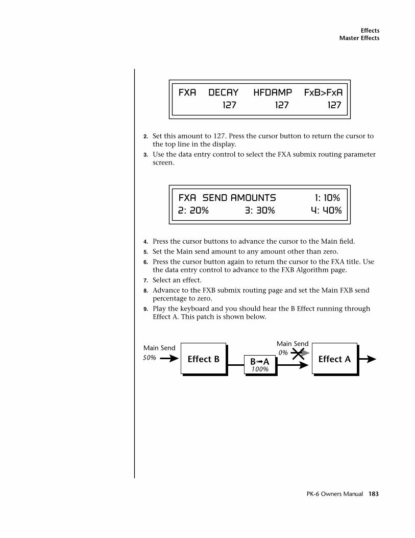
EffectsMaster Effects
2. Set this amount to 127. Press the cursor button to return the cursor to the top line in the display.
3. Use the data entry control to select the FXA submix routing parameter screen.
4. Press the cursor buttons to advance the cursor to the Main field.
5. Set the Main send amount to any amount other than zero.
6. Press the cursor button again to return the cursor to the FXA title. Use the data entry control to advance to the FXB Algorithm page.
7. Select an effect.
8. Advance to the FXB submix routing page and set the Main FXB send percentage to zero.
9. Play the keyboard and you should hear the B Effect running through Effect A. This patch is shown below.
FXA DECAY HFDAMP FxB>FxA 127 127 127
FXA SEND AMOUNTS 1: 10% 2: 20% 3: 30% 4: 40%
Effect BMain Send
Main Send
Effect A50%
100%
0%B➟A
PK-6 Owners Manual 183
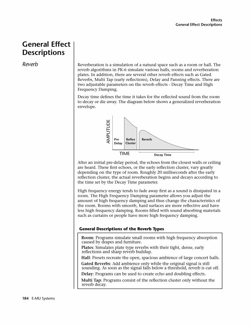
EffectsGeneral Effect Descriptions
General Effect Descriptions
Reverb Reverberation is a simulation of a natural space such as a room or hall. The reverb algorithms in PK-6 simulate various halls, rooms and reverberation plates. In addition, there are several other reverb effects such as Gated Reverbs, Multi Tap (early reflections), Delay and Panning effects. There are two adjustable parameters on the reverb effects - Decay Time and High Frequency Damping.
Decay time defines the time it takes for the reflected sound from the room to decay or die away. The diagram below shows a generalized reverberation envelope.
After an initial pre-delay period, the echoes from the closest walls or ceiling are heard. These first echoes, or the early reflection cluster, vary greatly depending on the type of room. Roughly 20 milliseconds after the early reflection cluster, the actual reverberation begins and decays according to the time set by the Decay Time parameter.
High frequency energy tends to fade away first as a sound is dissipated in a room. The High Frequency Damping parameter allows you adjust the amount of high frequency damping and thus change the characteristics of the room. Rooms with smooth, hard surfaces are more reflective and have less high frequency damping. Rooms filled with sound absorbing materials such as curtains or people have more high frequency damping.
TIME
AM
PLIT
UD
E
PreDelay
ReverbReflexCluster
Decay Time
General Descriptions of the Reverb Types
Room: Programs simulate small rooms with high frequency absorption caused by drapes and furniture.Plates: Simulates plate type reverbs with their tight, dense, early reflections and sharp reverb buildup.Hall: Presets recreate the open, spacious ambience of large concert halls.Gated Reverbs: Add ambience only while the original signal is still sounding. As soon as the signal falls below a threshold, reverb is cut off.Delay: Programs can be used to create echo and doubling effects.
Multi Tap: Programs consist of the reflection cluster only without the reverb decay.
184 E-MU Systems
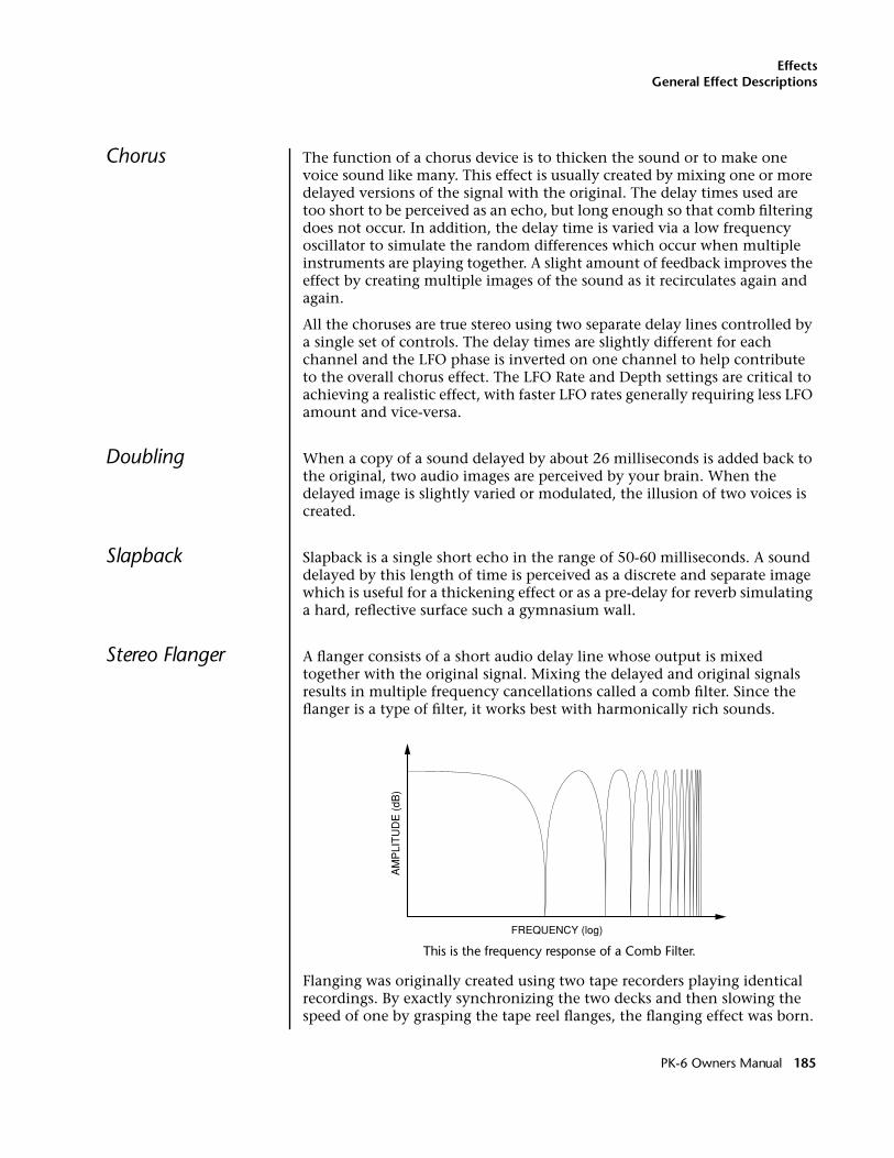
EffectsGeneral Effect Descriptions
Chorus The function of a chorus device is to thicken the sound or to make one voice sound like many. This effect is usually created by mixing one or more delayed versions of the signal with the original. The delay times used are too short to be perceived as an echo, but long enough so that comb filtering does not occur. In addition, the delay time is varied via a low frequency oscillator to simulate the random differences which occur when multiple instruments are playing together. A slight amount of feedback improves the effect by creating multiple images of the sound as it recirculates again and again.
All the choruses are true stereo using two separate delay lines controlled by a single set of controls. The delay times are slightly different for each channel and the LFO phase is inverted on one channel to help contribute to the overall chorus effect. The LFO Rate and Depth settings are critical to achieving a realistic effect, with faster LFO rates generally requiring less LFO amount and vice-versa.
Doubling When a copy of a sound delayed by about 26 milliseconds is added back to the original, two audio images are perceived by your brain. When the delayed image is slightly varied or modulated, the illusion of two voices is created.
Slapback Slapback is a single short echo in the range of 50-60 milliseconds. A sound delayed by this length of time is perceived as a discrete and separate image which is useful for a thickening effect or as a pre-delay for reverb simulating a hard, reflective surface such a gymnasium wall.
Stereo Flanger A flanger consists of a short audio delay line whose output is mixed together with the original signal. Mixing the delayed and original signals results in multiple frequency cancellations called a comb filter. Since the flanger is a type of filter, it works best with harmonically rich sounds.
This is the frequency response of a Comb Filter.
Flanging was originally created using two tape recorders playing identical recordings. By exactly synchronizing the two decks and then slowing the speed of one by grasping the tape reel flanges, the flanging effect was born.
PK-6 Owners Manual 185
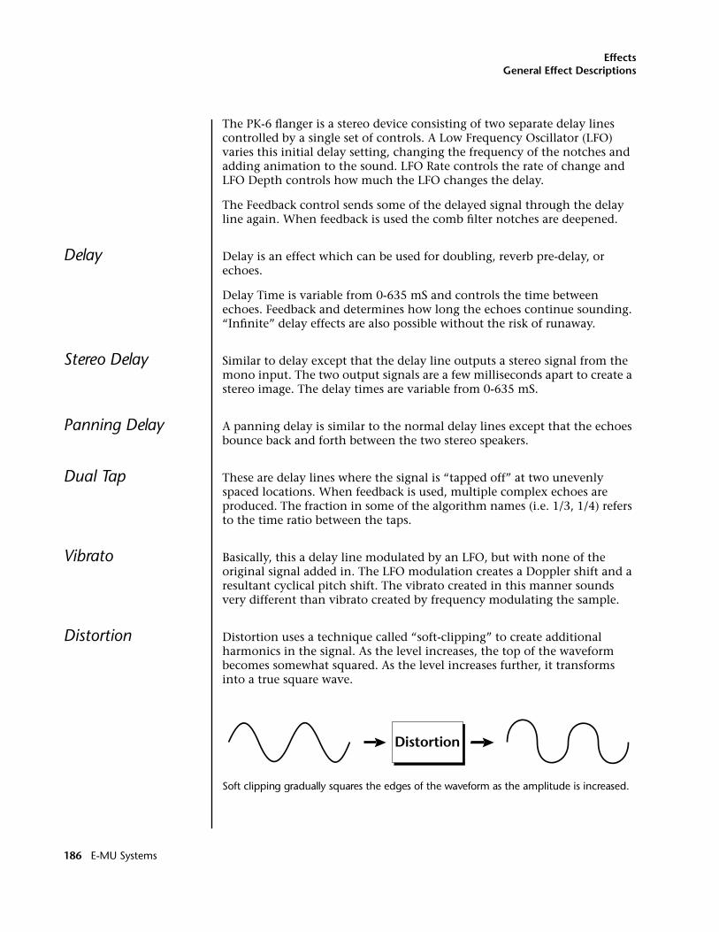
EffectsGeneral Effect Descriptions
The PK-6 flanger is a stereo device consisting of two separate delay lines controlled by a single set of controls. A Low Frequency Oscillator (LFO) varies this initial delay setting, changing the frequency of the notches and adding animation to the sound. LFO Rate controls the rate of change and LFO Depth controls how much the LFO changes the delay.
The Feedback control sends some of the delayed signal through the delay line again. When feedback is used the comb filter notches are deepened.
Delay Delay is an effect which can be used for doubling, reverb pre-delay, or echoes.
Delay Time is variable from 0-635 mS and controls the time between echoes. Feedback and determines how long the echoes continue sounding. “Infinite” delay effects are also possible without the risk of runaway.
Stereo Delay Similar to delay except that the delay line outputs a stereo signal from the mono input. The two output signals are a few milliseconds apart to create a stereo image. The delay times are variable from 0-635 mS.
Panning Delay A panning delay is similar to the normal delay lines except that the echoes bounce back and forth between the two stereo speakers.
Dual Tap These are delay lines where the signal is “tapped off” at two unevenly spaced locations. When feedback is used, multiple complex echoes are produced. The fraction in some of the algorithm names (i.e. 1/3, 1/4) refers to the time ratio between the taps.
Vibrato Basically, this a delay line modulated by an LFO, but with none of the original signal added in. The LFO modulation creates a Doppler shift and a resultant cyclical pitch shift. The vibrato created in this manner sounds very different than vibrato created by frequency modulating the sample.
Distortion Distortion uses a technique called “soft-clipping” to create additional harmonics in the signal. As the level increases, the top of the waveform becomes somewhat squared. As the level increases further, it transforms into a true square wave.
Soft clipping gradually squares the edges of the waveform as the amplitude is increased.
186 E-MU Systems
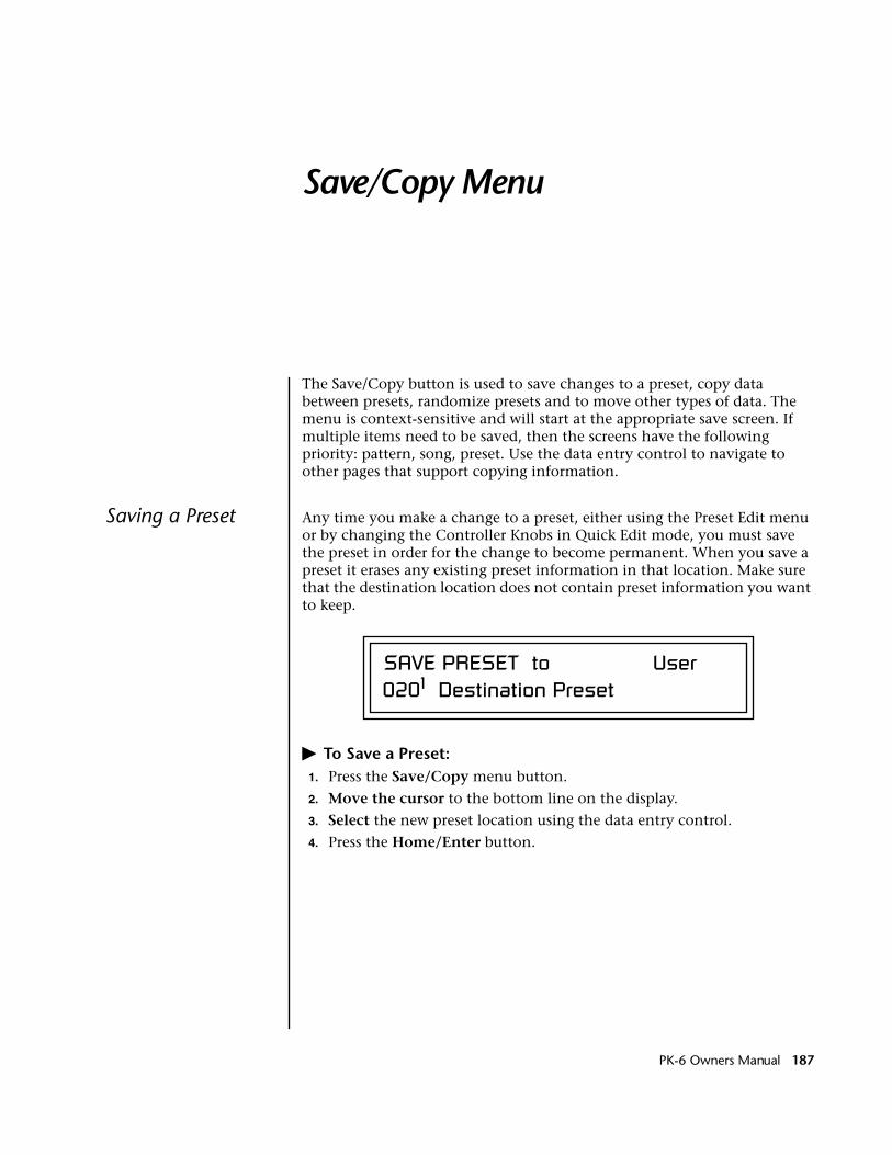
Save/Copy Menu
The Save/Copy button is used to save changes to a preset, copy data between presets, randomize presets and to move other types of data. The menu is context-sensitive and will start at the appropriate save screen. If multiple items need to be saved, then the screens have the following priority: pattern, song, preset. Use the data entry control to navigate to other pages that support copying information.
Saving a Preset Any time you make a change to a preset, either using the Preset Edit menu or by changing the Controller Knobs in Quick Edit mode, you must save the preset in order for the change to become permanent. When you save a preset it erases any existing preset information in that location. Make sure that the destination location does not contain preset information you want to keep.
� To Save a Preset:1. Press the Save/Copy menu button.
2. Move the cursor to the bottom line on the display.
3. Select the new preset location using the data entry control.
4. Press the Home/Enter button.
SAVE PRESET to User0201 Destination Preset
PK-6 Owners Manual 187
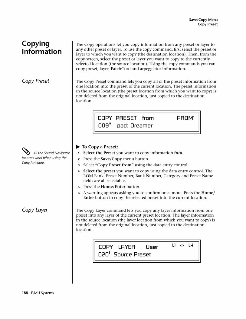
Save/Copy MenuCopy Preset
Copying Information
The Copy operations let you copy information from any preset or layer to any other preset or layer. To use the copy command, first select the preset or layer to which you want to copy (the destination location). Then, from the copy screen, select the preset or layer you want to copy to the currently selected location (the source location). Using the copy commands you can copy preset, layer, PatchCord and arpeggiator information.
Copy Preset The Copy Preset command lets you copy all of the preset information from one location into the preset of the current location. The preset information in the source location (the preset location from which you want to copy) is not deleted from the original location, just copied to the destination location.
� To Copy a Preset: All the Sound Navigator features work when using the Copy functions.
1. Select the Preset you want to copy information into.
2. Press the Save/Copy menu button.
3. Select “Copy Preset from” using the data entry control.
4. Select the preset you want to copy using the data entry control. The ROM Bank, Preset Number, Bank Number, Category and Preset Name fields are all selectable.
5. Press the Home/Enter button.
6. A warning appears asking you to confirm once more. Press the Home/Enter button to copy the selected preset into the current location.
Copy Layer The Copy Layer command lets you copy any layer information from one preset into any layer of the current preset location. The layer information in the source location (the layer location from which you want to copy) is not deleted from the original location, just copied to the destination location.
COPY PRESET from PROM10093 pad: Dreamer
COPY LAYER User L1 -> L4
0201 Source Preset
188 E-MU Systems
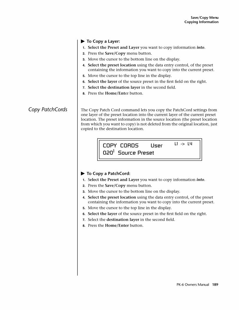
Save/Copy MenuCopying Information
� To Copy a Layer:1. Select the Preset and Layer you want to copy information into.
2. Press the Save/Copy menu button.
3. Move the cursor to the bottom line on the display.
4. Select the preset location using the data entry control, of the preset containing the information you want to copy into the current preset.
5. Move the cursor to the top line in the display.
6. Select the layer of the source preset in the first field on the right.
7. Select the destination layer in the second field.
8. Press the Home/Enter button.
Copy PatchCords The Copy Patch Cord command lets you copy the PatchCord settings from one layer of the preset location into the current layer of the current preset location. The preset information in the source location (the preset location from which you want to copy) is not deleted from the original location, just copied to the destination location.
� To Copy a PatchCord:1. Select the Preset and Layer you want to copy information into.
2. Press the Save/Copy menu button.
3. Move the cursor to the bottom line on the display.
4. Select the preset location using the data entry control, of the preset containing the information you want to copy into the current preset.
5. Move the cursor to the top line in the display.
6. Select the layer of the source preset in the first field on the right.
7. Select the destination layer in the second field.
8. Press the Home/Enter button.
COPY CORDS User L1 -> L4
0201 Source Preset
PK-6 Owners Manual 189
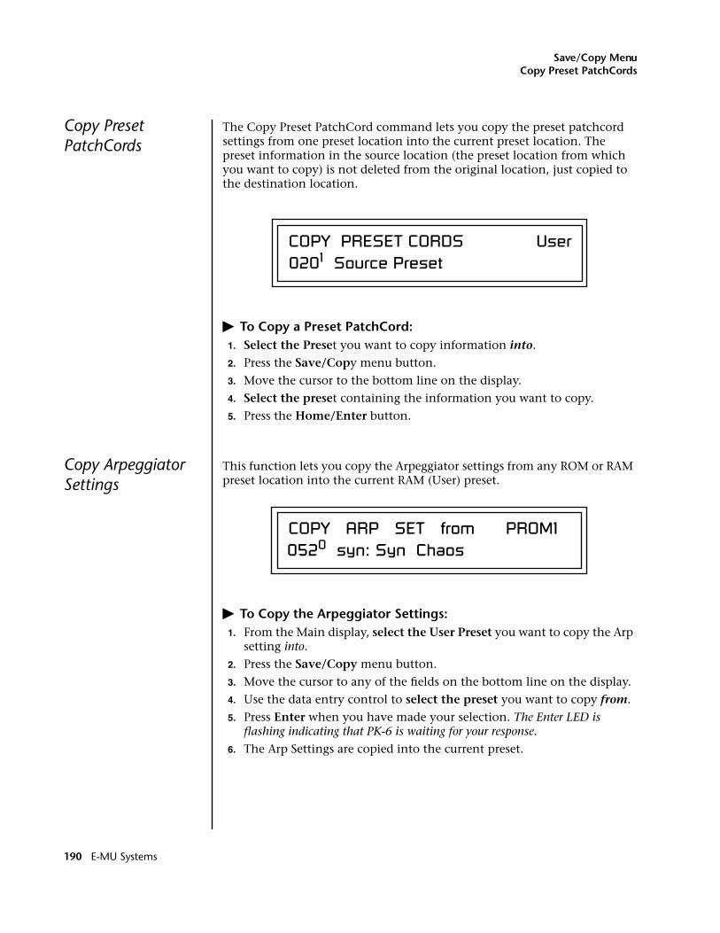
Save/Copy MenuCopy Preset PatchCords
Copy PresetPatchCords
The Copy Preset PatchCord command lets you copy the preset patchcord settings from one preset location into the current preset location. The preset information in the source location (the preset location from which you want to copy) is not deleted from the original location, just copied to the destination location.
� To Copy a Preset PatchCord:1. Select the Preset you want to copy information into.
2. Press the Save/Copy menu button.
3. Move the cursor to the bottom line on the display.
4. Select the preset containing the information you want to copy.
5. Press the Home/Enter button.
Copy Arpeggiator Settings
This function lets you copy the Arpeggiator settings from any ROM or RAM preset location into the current RAM (User) preset.
� To Copy the Arpeggiator Settings:1. From the Main display, select the User Preset you want to copy the Arp
setting into.
2. Press the Save/Copy menu button.
3. Move the cursor to any of the fields on the bottom line on the display.
4. Use the data entry control to select the preset you want to copy from.
5. Press Enter when you have made your selection. The Enter LED is flashing indicating that PK-6 is waiting for your response.
6. The Arp Settings are copied into the current preset.
COPY PRESET CORDS User 0201 Source Preset
COPY ARP SET from PROM10520 syn: Syn Chaos
190 E-MU Systems
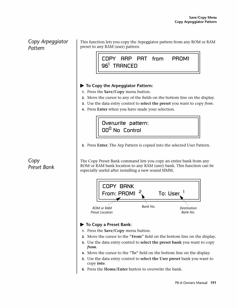
Save/Copy MenuCopy Arpeggiator Pattern
Copy Arpeggiator Pattern
This function lets you copy the Arpeggiator pattern from any ROM or RAM preset to any RAM (user) pattern.
� To Copy the Arpeggiator Pattern:1. Press the Save/Copy menu button.
2. Move the cursor to any of the fields on the bottom line on the display.
3. Use the data entry control to select the preset you want to copy from.
4. Press Enter when you have made your selection.
5. Press Enter. The Arp Pattern is copied into the selected User Pattern.
CopyPreset Bank
The Copy Preset Bank command lets you copy an entire bank from any ROM or RAM bank location to any RAM (user) bank. This function can be especially useful after installing a new sound SIMM.
� To Copy a Preset Bank:1. Press the Save/Copy menu button.
2. Move the cursor to the “From” field on the bottom line on the display.
3. Use the data entry control to select the preset bank you want to copy from.
4. Move the cursor to the “To” field on the bottom line on the display.
5. Use the data entry control to select the User preset bank you want to copy into.
6. Press the Home/Enter button to overwrite the bank.
COPY ARP PAT from PROM1961 TRANCED
Overwrite pattern:000 No Control
COPY BANKFrom: PROM1 2 To: User 1
ROM or RAMPreset Location
Bank No. Destination Bank No.
PK-6 Owners Manual 191
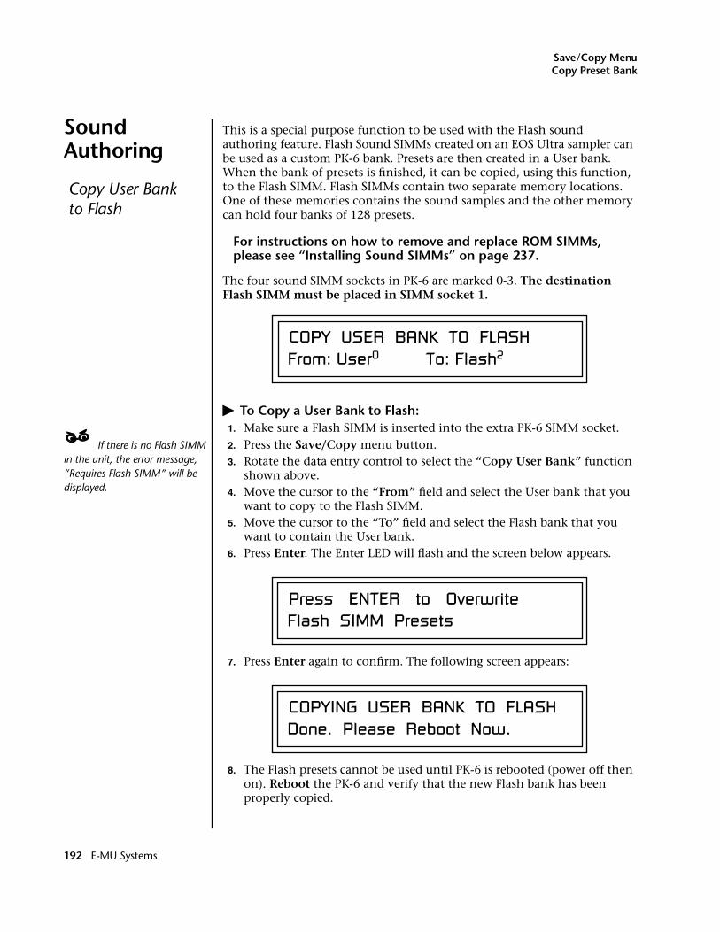
Save/Copy MenuCopy Preset Bank
Sound Authoring
This is a special purpose function to be used with the Flash sound authoring feature. Flash Sound SIMMs created on an EOS Ultra sampler can be used as a custom PK-6 bank. Presets are then created in a User bank. When the bank of presets is finished, it can be copied, using this function, to the Flash SIMM. Flash SIMMs contain two separate memory locations. One of these memories contains the sound samples and the other memory can hold four banks of 128 presets.
For instructions on how to remove and replace ROM SIMMs, please see “Installing Sound SIMMs” on page 237.
The four sound SIMM sockets in PK-6 are marked 0-3. The destination Flash SIMM must be placed in SIMM socket 1.
� To Copy a User Bank to Flash:1. Make sure a Flash SIMM is inserted into the extra PK-6 SIMM socket.
____ If there is no Flash SIMM in the unit, the error message, “Requires Flash SIMM” will be displayed.
2. Press the Save/Copy menu button.3. Rotate the data entry control to select the “Copy User Bank” function
shown above.4. Move the cursor to the “From” field and select the User bank that you
want to copy to the Flash SIMM.5. Move the cursor to the “To” field and select the Flash bank that you
want to contain the User bank.6. Press Enter. The Enter LED will flash and the screen below appears.
7. Press Enter again to confirm. The following screen appears:
8. The Flash presets cannot be used until PK-6 is rebooted (power off then on). Reboot the PK-6 and verify that the new Flash bank has been properly copied.
Copy User Bank to Flash
COPY USER BANK TO FLASHFrom: User0 To: Flash2
Press ENTER to OverwriteFlash SIMM Presets
COPYING USER BANK TO FLASHDone. Please Reboot Now.
192 E-MU Systems
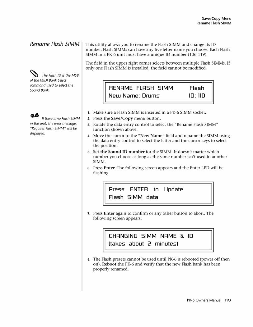
Save/Copy MenuRename Flash SIMM
Rename Flash SIMM This utility allows you to rename the Flash SIMM and change its ID number. Flash SIMMs can have any five letter name you choose. Each Flash SIMM in a PK-6 unit must have a unique ID number (106-119).
The field in the upper right corner selects between multiple Flash SIMMs. If only one Flash SIMM is installed, the field cannot be modified.
The Flash ID is the MSB of the MIDI Bank Select command used to select the Sound Bank.
1. Make sure a Flash SIMM is inserted in a PK-6 SIMM socket.____ If there is no Flash SIMM in the unit, the error message, “Requires Flash SIMM” will be displayed.
2. Press the Save/Copy menu button.
3. Rotate the data entry control to select the “Rename Flash SIMM” function shown above.
4. Move the cursor to the “New Name” field and rename the SIMM using the data entry control to select the letter and the cursor keys to select the position.
5. Set the Sound ID number for the SIMM. It doesn’t matter which number you choose as long as the same number isn’t used in another SIMM.
6. Press Enter. The following screen appears and the Enter LED will be flashing.
7. Press Enter again to confirm or any other button to abort. The following screen appears:
8. The Flash presets cannot be used until PK-6 is rebooted (power off then on). Reboot the PK-6 and verify that the new Flash bank has been properly renamed.
RENAME FLASH SIMM Flash New Name: Drums ID: 110
Press ENTER to UpdateFlash SIMM data
CHANGING SIMM NAME & ID(takes about 2 minutes)
PK-6 Owners Manual 193
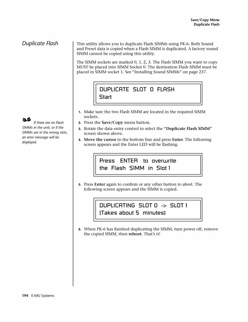
Save/Copy MenuDuplicate Flash
Duplicate Flash This utility allows you to duplicate Flash SIMMs using PK-6. Both Sound and Preset data is copied when a Flash SIMM is duplicated. A factory sound SIMM cannot be copied using this utility.
The SIMM sockets are marked 0, 1, 2, 3. The Flash SIMM you want to copy MUST be placed into SIMM Socket 0. The destination Flash SIMM must be placed in SIMM socket 1. See “Installing Sound SIMMs” on page 237.
1. Make sure the two Flash SIMM are located in the required SIMM sockets.
____ If there are no Flash SIMMs in the unit, or if the SIMMs are in the wrong slots, an error message will be displayed.
2. Press the Save/Copy menu button.
3. Rotate the data entry control to select the “Duplicate Flash SIMM” screen shown above.
4. Move the cursor to the bottom line and press Enter. The following screen appears and the Enter LED will be flashing.
5. Press Enter again to confirm or any other button to abort. The following screen appears and the SIMM is copied.
6. When PK-6 has finished duplicating the SIMM, turn power off, remove the copied SIMM, then reboot. That’s it!
DUPLICATE SLOT 0 FLASH Start
Press ENTER to overwritethe Flash SIMM in Slot 1
DUPLICATING SLOT 0 -> SLOT 1(Takes about 5 minutes)
194 E-MU Systems
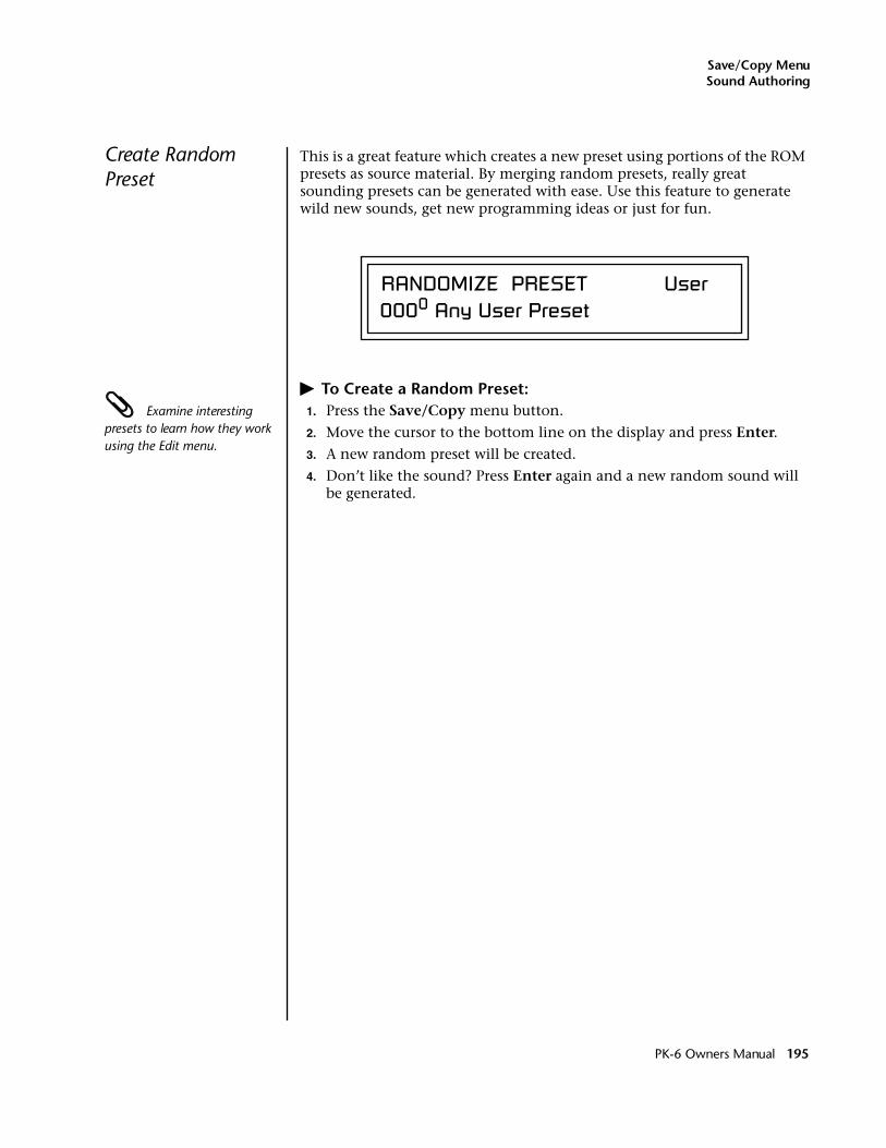
Save/Copy MenuSound Authoring
Create Random Preset
This is a great feature which creates a new preset using portions of the ROM presets as source material. By merging random presets, really great sounding presets can be generated with ease. Use this feature to generate wild new sounds, get new programming ideas or just for fun.
� To Create a Random Preset: Examine interesting presets to learn how they work using the Edit menu.
1. Press the Save/Copy menu button.
2. Move the cursor to the bottom line on the display and press Enter.
3. A new random preset will be created.
4. Don’t like the sound? Press Enter again and a new random sound will be generated.
RANDOMIZE PRESET User0000 Any User Preset
PK-6 Owners Manual 195
Save/Copy MenuCreate Random Preset
196 E-MU Systems
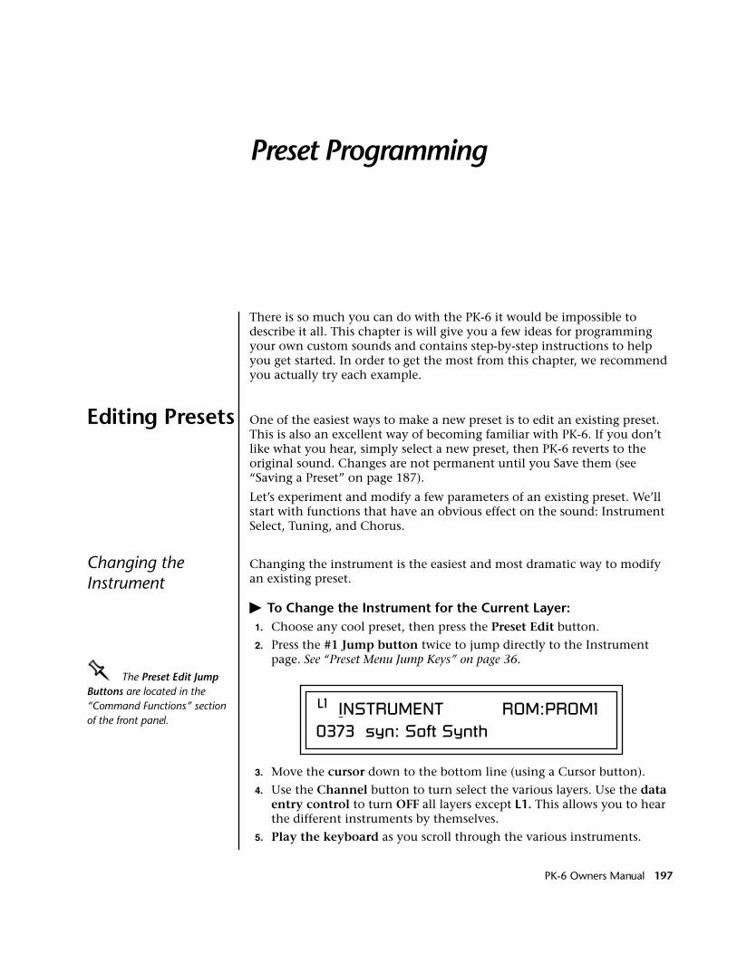
Preset Programming
There is so much you can do with the PK-6 it would be impossible to describe it all. This chapter is will give you a few ideas for programming your own custom sounds and contains step-by-step instructions to help you get started. In order to get the most from this chapter, we recommend you actually try each example.
Editing Presets One of the easiest ways to make a new preset is to edit an existing preset. This is also an excellent way of becoming familiar with PK-6. If you don’t like what you hear, simply select a new preset, then PK-6 reverts to the original sound. Changes are not permanent until you Save them (see “Saving a Preset” on page 187).
Let’s experiment and modify a few parameters of an existing preset. We’ll start with functions that have an obvious effect on the sound: Instrument Select, Tuning, and Chorus.
Changing the Instrument
Changing the instrument is the easiest and most dramatic way to modify an existing preset.
� To Change the Instrument for the Current Layer:1. Choose any cool preset, then press the Preset Edit button.
2. Press the #1 Jump button twice to jump directly to the Instrument page. See “Preset Menu Jump Keys” on page 36.
OOOO The Preset Edit Jump Buttons are located in the “Command Functions” section of the front panel.
3. Move the cursor down to the bottom line (using a Cursor button).
4. Use the Channel button to turn select the various layers. Use the data entry control to turn OFF all layers except L1. This allows you to hear the different instruments by themselves.
5. Play the keyboard as you scroll through the various instruments.
L1 INSTRUMENT ROM:PROM10373 syn: Soft Synth
PK-6 Owners Manual 197
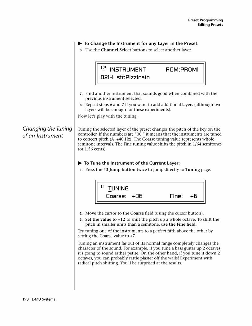
Preset ProgrammingEditing Presets
� To Change the Instrument for any Layer in the Preset:6. Use the Channel Select buttons to select another layer.
7. Find another instrument that sounds good when combined with the previous instrument selected.
8. Repeat steps 6 and 7 if you want to add additional layers (although two layers will be enough for these experiments).
Now let’s play with the tuning.
Changing the Tuning of an Instrument
Tuning the selected layer of the preset changes the pitch of the key on the controller. If the numbers are “00,” it means that the instruments are tuned to concert pitch (A=440 Hz). The Coarse tuning value represents whole semitone intervals. The Fine tuning value shifts the pitch in 1/64 semitones (or 1.56 cents).
� To Tune the Instrument of the Current Layer:1. Press the #3 Jump button twice to jump directly to Tuning page.
2. Move the cursor to the Coarse field (using the cursor button).
3. Set the value to +12 to shift the pitch up a whole octave. To shift the pitch in smaller units than a semitone, use the Fine field.
Try tuning one of the instruments to a perfect fifth above the other by setting the Coarse value to +7.
Tuning an instrument far out of its normal range completely changes the character of the sound. For example, if you tune a bass guitar up 2 octaves, it's going to sound rather petite. On the other hand, if you tune it down 2 octaves, you can probably rattle plaster off the walls! Experiment with radical pitch shifting. You'll be surprised at the results.
L2 INSTRUMENT ROM:PROM10214 str:Pizzicato
L1 TUNING Coarse: +36 Fine: +6
198 E-MU Systems
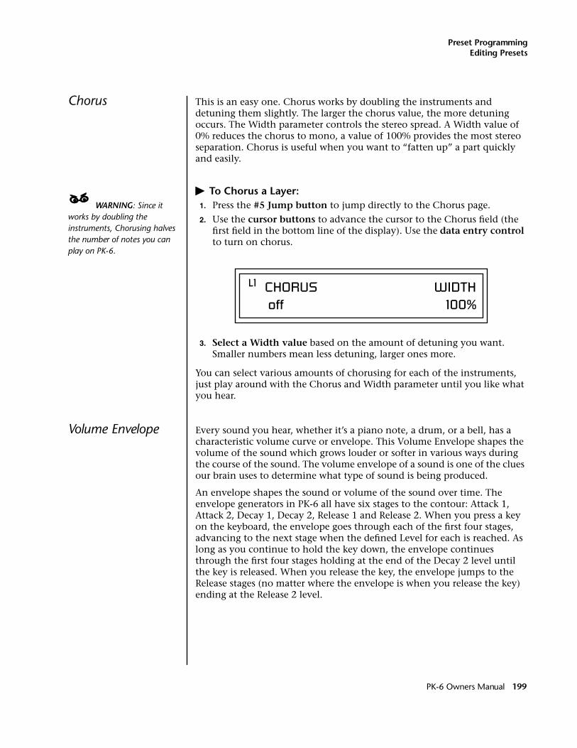
Preset ProgrammingEditing Presets
Chorus This is an easy one. Chorus works by doubling the instruments and detuning them slightly. The larger the chorus value, the more detuning occurs. The Width parameter controls the stereo spread. A Width value of 0% reduces the chorus to mono, a value of 100% provides the most stereo separation. Chorus is useful when you want to “fatten up” a part quickly and easily.
� To Chorus a Layer:____ WARNING: Since it works by doubling the instruments, Chorusing halves the number of notes you can play on PK-6.
1. Press the #5 Jump button to jump directly to the Chorus page.
2. Use the cursor buttons to advance the cursor to the Chorus field (the first field in the bottom line of the display). Use the data entry control to turn on chorus.
3. Select a Width value based on the amount of detuning you want. Smaller numbers mean less detuning, larger ones more.
You can select various amounts of chorusing for each of the instruments, just play around with the Chorus and Width parameter until you like what you hear.
Volume Envelope Every sound you hear, whether it’s a piano note, a drum, or a bell, has a characteristic volume curve or envelope. This Volume Envelope shapes the volume of the sound which grows louder or softer in various ways during the course of the sound. The volume envelope of a sound is one of the clues our brain uses to determine what type of sound is being produced.
An envelope shapes the sound or volume of the sound over time. The envelope generators in PK-6 all have six stages to the contour: Attack 1, Attack 2, Decay 1, Decay 2, Release 1 and Release 2. When you press a key on the keyboard, the envelope goes through each of the first four stages, advancing to the next stage when the defined Level for each is reached. As long as you continue to hold the key down, the envelope continues through the first four stages holding at the end of the Decay 2 level until the key is released. When you release the key, the envelope jumps to the Release stages (no matter where the envelope is when you release the key) ending at the Release 2 level.
L1 CHORUS WIDTH off 100%
PK-6 Owners Manual 199
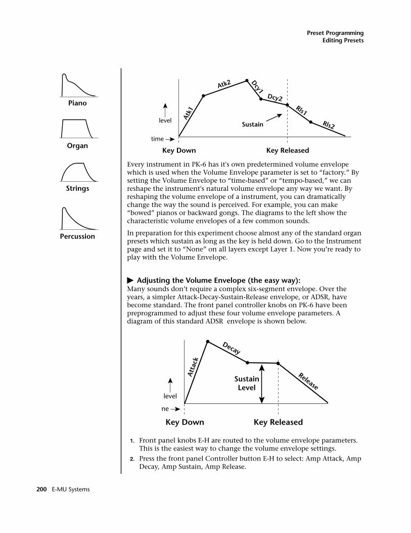
Preset ProgrammingEditing Presets
Every instrument in PK-6 has it's own predetermined volume envelope which is used when the Volume Envelope parameter is set to “factory.” By setting the Volume Envelope to “time-based” or “tempo-based,” we can reshape the instrument's natural volume envelope any way we want. By reshaping the volume envelope of a instrument, you can dramatically change the way the sound is perceived. For example, you can make “bowed” pianos or backward gongs. The diagrams to the left show the characteristic volume envelopes of a few common sounds.
In preparation for this experiment choose almost any of the standard organ presets which sustain as long as the key is held down. Go to the Instrument page and set it to “None” on all layers except Layer 1. Now you’re ready to play with the Volume Envelope.
� Adjusting the Volume Envelope (the easy way):Many sounds don’t require a complex six-segment envelope. Over the years, a simpler Attack-Decay-Sustain-Release envelope, or ADSR, have become standard. The front panel controller knobs on PK-6 have been preprogrammed to adjust these four volume envelope parameters. A diagram of this standard ADSR envelope is shown below.
1. Front panel knobs E-H are routed to the volume envelope parameters. This is the easiest way to change the volume envelope settings.
2. Press the front panel Controller button E-H to select: Amp Attack, Amp Decay, Amp Sustain, Amp Release.
Atk1
Atk2 Dcy1
Dcy2Rls1
Rls2
Key Down Key Released
Sustain
time
level
Att
ack
Decay
Release
Key Down Key Released
SustainLevel
me
level
Percussion
Piano
Organ
Strings
200 E-MU Systems
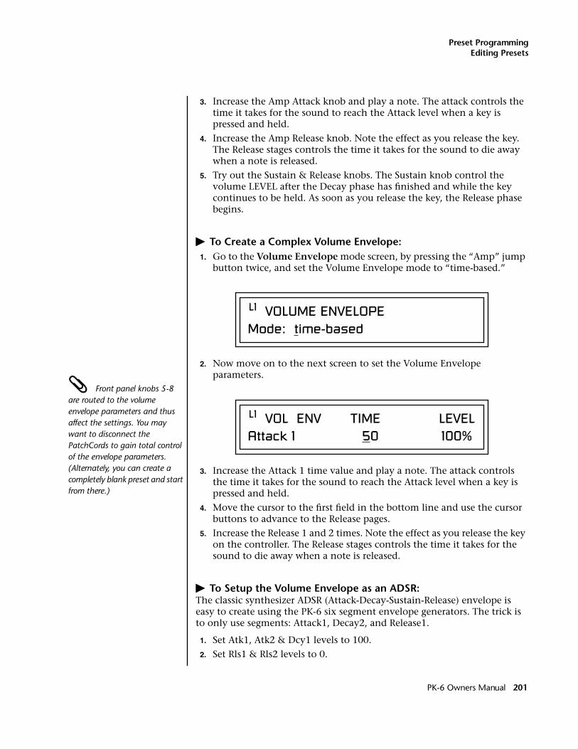
Preset ProgrammingEditing Presets
3. Increase the Amp Attack knob and play a note. The attack controls the time it takes for the sound to reach the Attack level when a key is pressed and held.
4. Increase the Amp Release knob. Note the effect as you release the key. The Release stages controls the time it takes for the sound to die away when a note is released.
5. Try out the Sustain & Release knobs. The Sustain knob control the volume LEVEL after the Decay phase has finished and while the key continues to be held. As soon as you release the key, the Release phase begins.
� To Create a Complex Volume Envelope:1. Go to the Volume Envelope mode screen, by pressing the “Amp” jump
button twice, and set the Volume Envelope mode to “time-based.”
2. Now move on to the next screen to set the Volume Envelope parameters.
Front panel knobs 5-8 are routed to the volume envelope parameters and thus affect the settings. You may want to disconnect the PatchCords to gain total control of the envelope parameters. (Alternately, you can create a completely blank preset and start from there.)
3. Increase the Attack 1 time value and play a note. The attack controls the time it takes for the sound to reach the Attack level when a key is pressed and held.
4. Move the cursor to the first field in the bottom line and use the cursor buttons to advance to the Release pages.
5. Increase the Release 1 and 2 times. Note the effect as you release the key on the controller. The Release stages controls the time it takes for the sound to die away when a note is released.
� To Setup the Volume Envelope as an ADSR:The classic synthesizer ADSR (Attack-Decay-Sustain-Release) envelope is easy to create using the PK-6 six segment envelope generators. The trick is to only use segments: Attack1, Decay2, and Release1.
1. Set Atk1, Atk2 & Dcy1 levels to 100.
2. Set Rls1 & Rls2 levels to 0.
L1 VOLUME ENVELOPEMode: time-based
L1 VOL ENV TIME LEVELAttack 1 50 100%
PK-6 Owners Manual 201
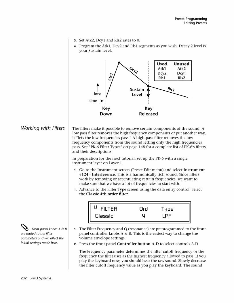
Preset ProgrammingEditing Presets
3. Set Atk2, Dcy1 and Rls2 rates to 0.
4. Program the Atk1, Dcy2 and Rls1 segments as you wish. Decay 2 level is your Sustain level.
Working with Filters The filters make it possible to remove certain components of the sound. A low pass filter removes the high frequency components or put another way, it “lets the low frequencies pass.” A high-pass filter removes the low frequency components from the sound letting only the high frequencies pass. See “PK-6 Filter Types” on page 148 for a complete list of PK-6’s filters and their descriptions.
In preparation for the next tutorial, set up the PK-6 with a single instrument layer on Layer 1.
1. Go to the Instrument screen (Preset Edit menu) and select Instrument #124 - Interference. This is a harmonically rich sound. Since filters work by removing or accentuating certain frequencies, we want to make sure that we have a lot of frequencies to start with.
1. Advance to the Filter Type screen using the data entry control. Select the Classic 4th order filter.
Front panel knobs A & B are routed to the filter parameters and will affect the initial settings made here.
1. The Filter Frequency and Q (resonance) are preprogrammed to the front panel controller knobs A & B. This is the easiest way to change the volume envelope settings.
2. Press the front panel Controller button A-D to select controls A-D
The Frequency parameter determines the filter cutoff frequency or the frequency the filter uses as the highest frequency allowed to pass. If you play the keyboard now, you should hear the raw sound. Slowly decrease the filter cutoff frequency value as you play the keyboard. The sound
Atk
1
Dcy2
Rls1
KeyDown
KeyReleased
SustainLevel
time
level
UsedAtk1Dcy2Rls1
UnusedAtk2Dcy1Rls2
L1 FILTER Ord Type Classic 4 LPF
202 E-MU Systems
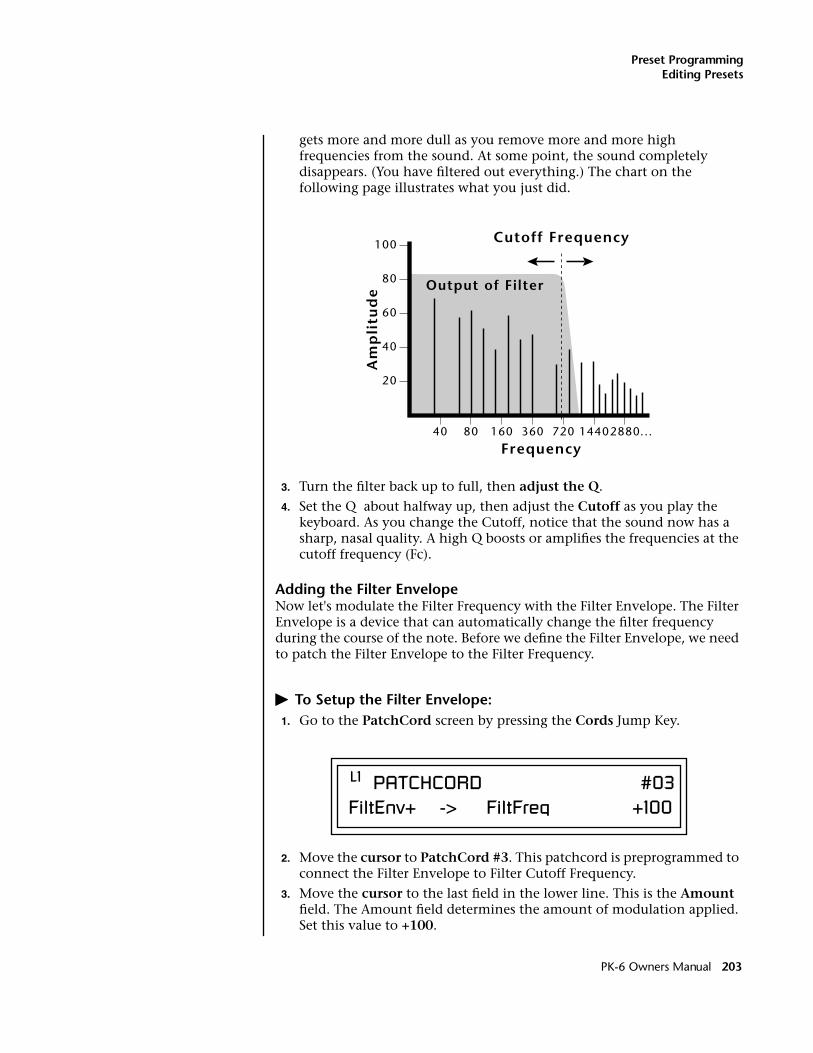
Preset ProgrammingEditing Presets
gets more and more dull as you remove more and more high frequencies from the sound. At some point, the sound completely disappears. (You have filtered out everything.) The chart on the following page illustrates what you just did.
3. Turn the filter back up to full, then adjust the Q.
4. Set the Q about halfway up, then adjust the Cutoff as you play the keyboard. As you change the Cutoff, notice that the sound now has a sharp, nasal quality. A high Q boosts or amplifies the frequencies at the cutoff frequency (Fc).
Adding the Filter EnvelopeNow let's modulate the Filter Frequency with the Filter Envelope. The Filter Envelope is a device that can automatically change the filter frequency during the course of the note. Before we define the Filter Envelope, we need to patch the Filter Envelope to the Filter Frequency.
� To Setup the Filter Envelope:1. Go to the PatchCord screen by pressing the Cords Jump Key.
2. Move the cursor to PatchCord #3. This patchcord is preprogrammed to connect the Filter Envelope to Filter Cutoff Frequency.
3. Move the cursor to the last field in the lower line. This is the Amount field. The Amount field determines the amount of modulation applied. Set this value to +100.
20
40
60
80
100
40 80 160 360 720 14402880
Frequency...
Am
pli
tud
e Output of Filter
Cutoff Frequency
L1 PATCHCORD #03FiltEnv+ -> FiltFreq +100
PK-6 Owners Manual 203
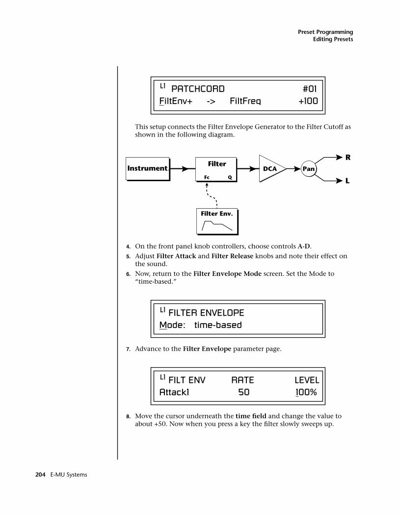
Preset ProgrammingEditing Presets
This setup connects the Filter Envelope Generator to the Filter Cutoff as shown in the following diagram.
4. On the front panel knob controllers, choose controls A-D.
5. Adjust Filter Attack and Filter Release knobs and note their effect on the sound.
6. Now, return to the Filter Envelope Mode screen. Set the Mode to “time-based.”
7. Advance to the Filter Envelope parameter page.
8. Move the cursor underneath the time field and change the value to about +50. Now when you press a key the filter slowly sweeps up.
L1 PATCHCORD #01FiltEnv+ -> FiltFreq +100
R
L
PanInstrumentFilter
DCA
Filter Env.
Fc Q
L1 FILTER ENVELOPEMode: time-based
L1 FILT ENV RATE LEVELAttack1 50 100%
204 E-MU Systems
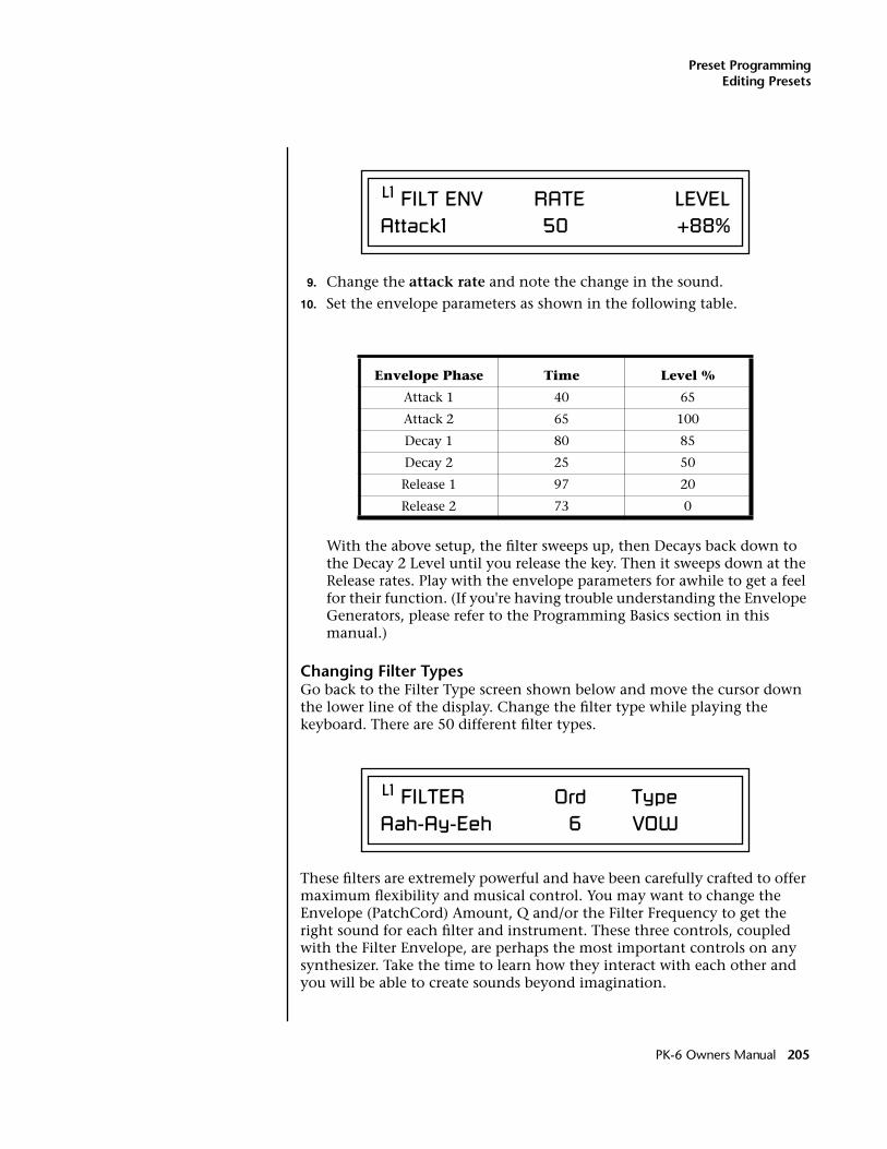
Preset ProgrammingEditing Presets
9. Change the attack rate and note the change in the sound.
10. Set the envelope parameters as shown in the following table.
With the above setup, the filter sweeps up, then Decays back down to the Decay 2 Level until you release the key. Then it sweeps down at the Release rates. Play with the envelope parameters for awhile to get a feel for their function. (If you're having trouble understanding the Envelope Generators, please refer to the Programming Basics section in this manual.)
Changing Filter TypesGo back to the Filter Type screen shown below and move the cursor down the lower line of the display. Change the filter type while playing the keyboard. There are 50 different filter types.
These filters are extremely powerful and have been carefully crafted to offer maximum flexibility and musical control. You may want to change the Envelope (PatchCord) Amount, Q and/or the Filter Frequency to get the right sound for each filter and instrument. These three controls, coupled with the Filter Envelope, are perhaps the most important controls on any synthesizer. Take the time to learn how they interact with each other and you will be able to create sounds beyond imagination.
Envelope Phase Time Level %
Attack 1 40 65
Attack 2 65 100
Decay 1 80 85
Decay 2 25 50
Release 1 97 20
Release 2 73 0
L1 FILT ENV RATE LEVELAttack1 50 +88%
L1 FILTER Ord Type Aah-Ay-Eeh 6 VOW
PK-6 Owners Manual 205
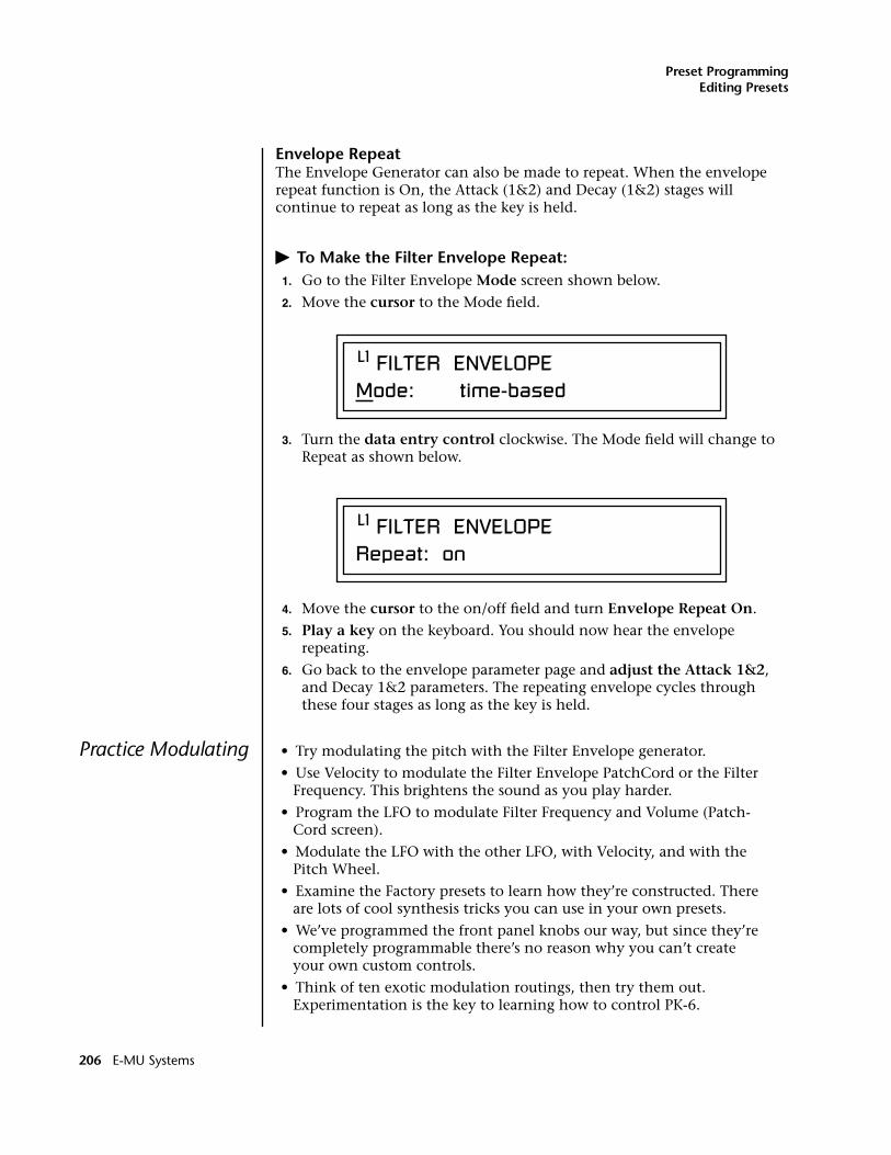
Preset ProgrammingEditing Presets
Envelope RepeatThe Envelope Generator can also be made to repeat. When the envelope repeat function is On, the Attack (1&2) and Decay (1&2) stages will continue to repeat as long as the key is held.
� To Make the Filter Envelope Repeat:1. Go to the Filter Envelope Mode screen shown below.
2. Move the cursor to the Mode field.
3. Turn the data entry control clockwise. The Mode field will change to Repeat as shown below.
4. Move the cursor to the on/off field and turn Envelope Repeat On.
5. Play a key on the keyboard. You should now hear the envelope repeating.
6. Go back to the envelope parameter page and adjust the Attack 1&2, and Decay 1&2 parameters. The repeating envelope cycles through these four stages as long as the key is held.
Practice Modulating • Try modulating the pitch with the Filter Envelope generator.
• Use Velocity to modulate the Filter Envelope PatchCord or the Filter Frequency. This brightens the sound as you play harder.
• Program the LFO to modulate Filter Frequency and Volume (Patch-Cord screen).
• Modulate the LFO with the other LFO, with Velocity, and with the Pitch Wheel.
• Examine the Factory presets to learn how they’re constructed. There are lots of cool synthesis tricks you can use in your own presets.
• We’ve programmed the front panel knobs our way, but since they’re completely programmable there’s no reason why you can’t create your own custom controls.
• Think of ten exotic modulation routings, then try them out. Experimentation is the key to learning how to control PK-6.
L1 FILTER ENVELOPE Mode: time-based
L1 FILTER ENVELOPE Repeat: on
206 E-MU Systems

Preset ProgrammingEditing Presets
Troubleshooting A common source of confusion when working with the filter envelope is that the Attack or Release parameters might not seem to be working correctly. If you are not getting the expected result, try to analyze the situation. There will be many times when you will have to stop for a minute and think, “What am I trying to do and why isn't it working?” When this happens (and it will), don't panic. Troubleshooting is a normal part of the synthesis process. Simply examine the various parameters and try to be as analytical as possible as you solve the problem. The solution is usually simple. (“The filter is already wide open and can't open any more.” or “Another PatchCord is connecting something to the parameter and affecting it.”) Learning to play any instrument takes a little patience and practice.
Referring to the diagram below which shows the PK-6 signal flow, notice that the DCA comes after the Filter. The DCA controls the final volume of the sound, so if the filter's release is longer than the release for the DCA, you won't hear it, because the DCA has already shut off the sound.
You’re getting the general idea by now. Remember not to select a new preset before saving the current one or all your changes will be lost (the preset reverts to the last saved version). If you want to save your creation, select the Save/Copy menu and select a destination preset location for your masterpiece, then press Enter.
Because you can save your work, it’s worth spending time to get the sound just right. When designing sounds you become an instrument builder as well as a musician. With PK-6 you can design the custom radical instru-ments you’ve always wanted!
R
L
PanInstrument DCAZ-PlaneFilter
PK-6 Owners Manual 207
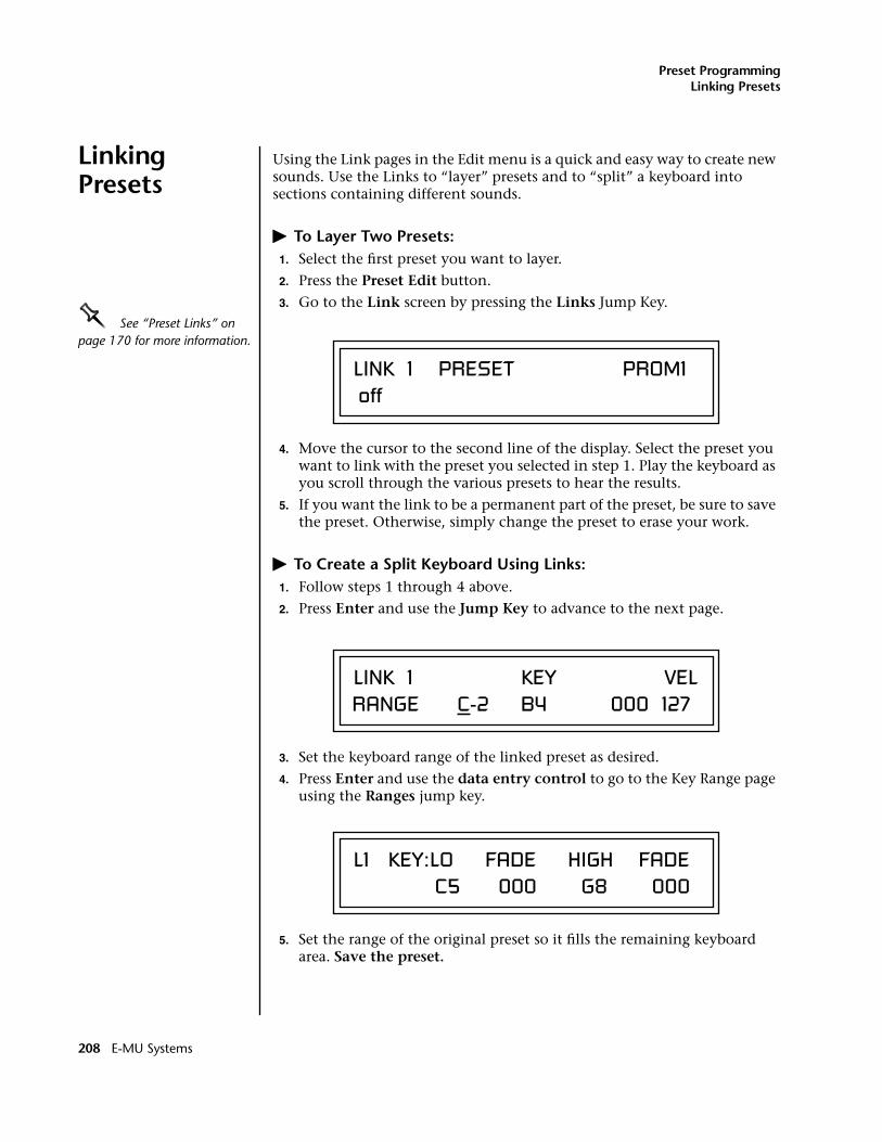
Preset ProgrammingLinking Presets
Linking Presets
Using the Link pages in the Edit menu is a quick and easy way to create new sounds. Use the Links to “layer” presets and to “split” a keyboard into sections containing different sounds.
� To Layer Two Presets:1. Select the first preset you want to layer.
2. Press the Preset Edit button.
3. Go to the Link screen by pressing the Links Jump Key.OOOO See “Preset Links” on page 170 for more information.
4. Move the cursor to the second line of the display. Select the preset you want to link with the preset you selected in step 1. Play the keyboard as you scroll through the various presets to hear the results.
5. If you want the link to be a permanent part of the preset, be sure to save the preset. Otherwise, simply change the preset to erase your work.
� To Create a Split Keyboard Using Links:1. Follow steps 1 through 4 above.
2. Press Enter and use the Jump Key to advance to the next page.
3. Set the keyboard range of the linked preset as desired.
4. Press Enter and use the data entry control to go to the Key Range page using the Ranges jump key.
5. Set the range of the original preset so it fills the remaining keyboard area. Save the preset.
LINK 1 PRESET PROM1 off
RANGE C-2 B4 000 127 LINK 1 KEY VEL
C5 000 G8 000 L1 KEY:LO FADE HIGH FADE
208 E-MU Systems
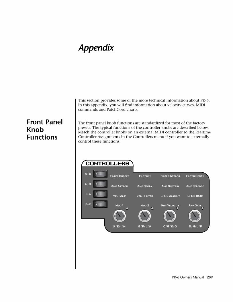
Appendix
This section provides some of the more technical information about PK-6. In this appendix, you will find information about velocity curves, MIDI commands and PatchCord charts.
Front Panel Knob Functions
The front panel knob functions are standardized for most of the factory presets. The typical functions of the controller knobs are described below. Match the controller knobs on an external MIDI controller to the Realtime Controller Assignments in the Controllers menu if you want to externally control these functions.
PK-6 Owners Manual 209
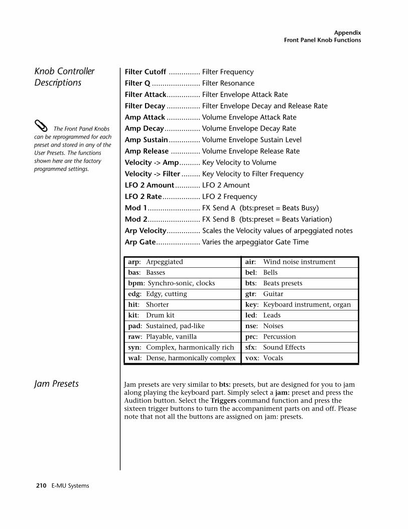
AppendixFront Panel Knob Functions
Knob Controller Descriptions
Filter Cutoff ............... Filter Frequency
Filter Q ....................... Filter Resonance
Filter Attack................ Filter Envelope Attack Rate
Filter Decay ................ Filter Envelope Decay and Release Rate
Amp Attack ................ Volume Envelope Attack Rate
The Front Panel Knobs can be reprogrammed for each preset and stored in any of the User Presets. The functions shown here are the factory programmed settings.
Amp Decay................. Volume Envelope Decay Rate
Amp Sustain ............... Volume Envelope Sustain Level
Amp Release .............. Volume Envelope Release Rate
Velocity -> Amp.......... Key Velocity to Volume
Velocity -> Filter ......... Key Velocity to Filter Frequency
LFO 2 Amount ............ LFO 2 Amount
LFO 2 Rate.................. LFO 2 Frequency
Mod 1......................... FX Send A (bts:preset = Beats Busy)
Mod 2......................... FX Send B (bts:preset = Beats Variation)
Arp Velocity................ Scales the Velocity values of arpeggiated notes
Arp Gate..................... Varies the arpeggiator Gate Time
Jam Presets Jam presets are very similar to bts: presets, but are designed for you to jam along playing the keyboard part. Simply select a jam: preset and press the Audition button. Select the Triggers command function and press the sixteen trigger buttons to turn the accompaniment parts on and off. Please note that not all the buttons are assigned on jam: presets.
arp: Arpeggiated air: Wind noise instrument
bas: Basses bel: Bells
bpm: Synchro-sonic, clocks bts: Beats presets
edg: Edgy, cutting gtr: Guitar
hit: Shorter key: Keyboard instrument, organ
kit: Drum kit led: Leads
pad: Sustained, pad-like nse: Noises
raw: Playable, vanilla prc: Percussion
syn: Complex, harmonically rich sfx: Sound Effects
wal: Dense, harmonically complex vox: Vocals
210 E-MU Systems
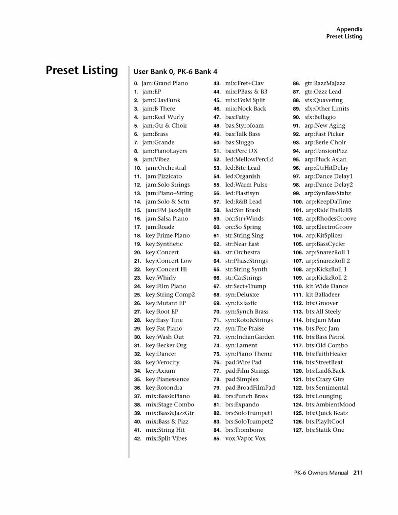
AppendixPreset Listing
Preset Listing User Bank 0, PK-6 Bank 4
0. jam:Grand Piano1. jam:EP2. jam:ClavFunk3. jam:B There4. jam:Reel Wurly5. jam:Gtr & Choir6. jam:Brass7. jam:Grande8. jam:PianoLayers9. jam:Vibez10. jam:Orchestral11. jam:Pizzicato12. jam:Solo Strings13. jam:Piano+String14. jam:Solo & Sctn15. jam:FM JazzSplit16. jam:Salsa Piano17. jam:Roadz18. key:Prime Piano19. key:Synthetic20. key:Concert21. key:Concert Low22. key:Concert Hi23. key:Whirly24. key:Film Piano25. key:String Comp226. key:Mutant EP27. key:Root EP28. key:Easy Tine29. key:Fat Piano30. key:Wash Out31. key:Becker Org32. key:Dancer33. key:Verocity34. key:Axium35. key:Pianessence36. key:Rotondra37. mix:Bass&Piano38. mix:Stage Combo39. mix:Bass&JazzGtr40. mix:Bass & Pizz41. mix:String Hit42. mix:Split Vibes
43. mix:Fret+Clav44. mix:PBass & B345. mix:F&M Split46. mix:Nock Back47. bas:Fatty48. bas:Styrofoam49. bas:Talk Bass50. bas:Sluggo51. bas:Perc DX52. led:MellowPercLd53. led:Bite Lead54. led:Organish55. led:Warm Pulse56. led:Plastisyn57. led:R&B Lead58. led:Sin Brash59. orc:Str+Winds60. orc:So Spring61. str:String Sing62. str:Near East63. str:Orchestra64. str:PhaseStrings65. str:String Synth66. str:CatStrings67. str:Sect+Trump68. syn:Deluxxe69. syn:Exlastic70. syn:Synch Brass71. syn:Koto&Strings72. syn:The Praise73. syn:IndianGarden74. syn:Lament75. syn:Piano Theme76. pad:Wire Pad77. pad:Film Strings78. pad:Simplex79. pad:BroadFilmPad80. brs:Punch Brass81. brs:Expando82. brs:SoloTrumpet183. brs:SoloTrumpet284. brs:Trombone85. vox:Vapor Vox
86. gtr:RazzMaJazz87. gtr:Ozzz Lead88. sfx:Quavering89. sfx:Other Limits90. sfx:Bellagio91. arp:New Aging92. arp:Fast Picker93. arp:Eerie Choir94. arp:TensionPizz95. arp:Pluck Asian96. arp:GtrHitDelay97. arp:Dance Delay198. arp:Dance Delay299. arp:SynBassStabz100. arp:KeepDaTime101. arp:RideTheBell$102. arp:RhodesGroove103. arp:ElectroGroov104. arp:KitSplicer105. arp:BassCycler106. arp:SnarezRoll 1107. arp:SnarezRoll 2108. arp:KickzRoll 1109. arp:KickzRoll 2110. kit:Wide Dance111. kit:Balladeer112. bts:Groover113. bts:All Steely114. bts:Jam Man115. bts:Perc Jam116. bts:Bass Patrol117. bts:Old Combo118. bts:FaithHealer119. bts:StreetBeat120. bts:Laid&Back121. bts:Crazy Gtrs122. bts:Sentimental123. bts:Lounging124. bts:AmbientMood125. bts:Quick Beatz126. bts:PlayItCool127. bts:Statik One
PK-6 Owners Manual 211
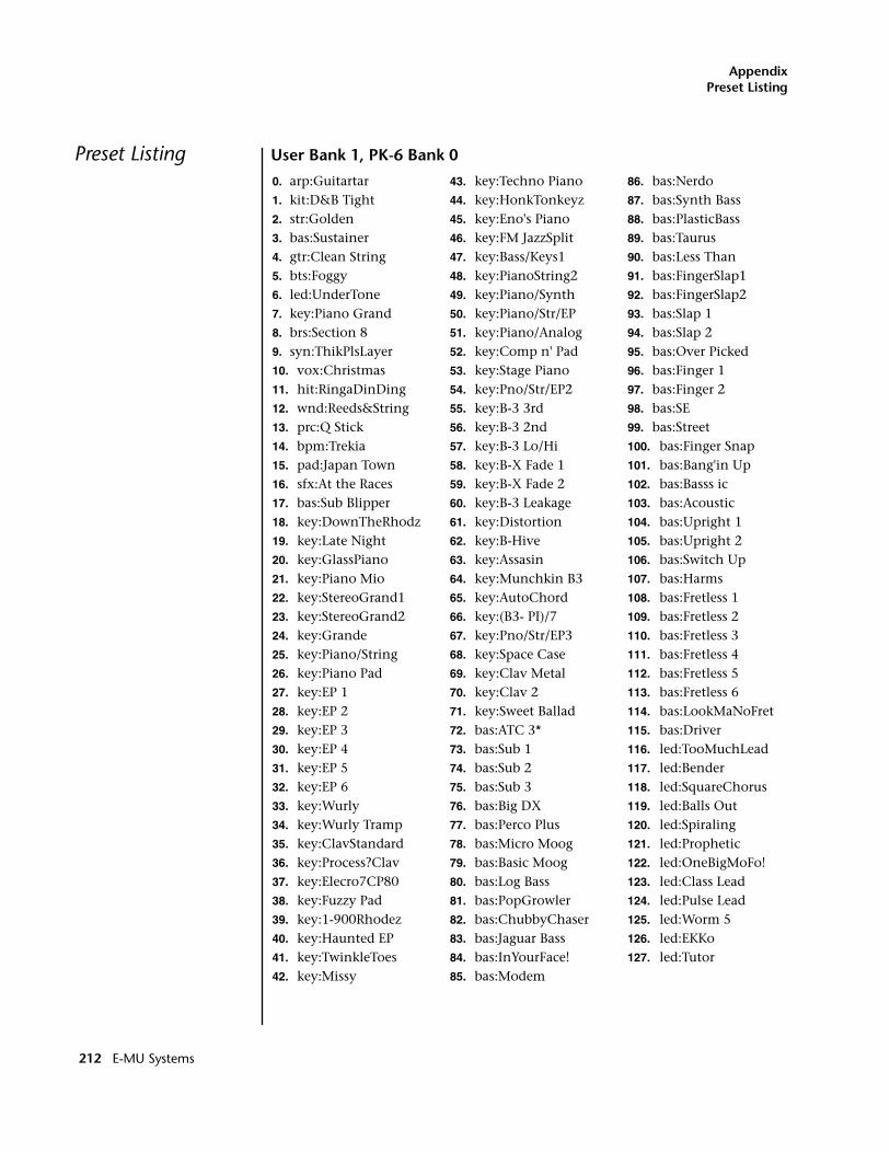
AppendixPreset Listing
Preset Listing User Bank 1, PK-6 Bank 0
0. arp:Guitartar1. kit:D&B Tight2. str:Golden3. bas:Sustainer4. gtr:Clean String5. bts:Foggy6. led:UnderTone7. key:Piano Grand8. brs:Section 89. syn:ThikPlsLayer10. vox:Christmas11. hit:RingaDinDing12. wnd:Reeds&String13. prc:Q Stick14. bpm:Trekia15. pad:Japan Town16. sfx:At the Races17. bas:Sub Blipper18. key:DownTheRhodz19. key:Late Night20. key:GlassPiano21. key:Piano Mio22. key:StereoGrand123. key:StereoGrand224. key:Grande25. key:Piano/String26. key:Piano Pad27. key:EP 128. key:EP 229. key:EP 330. key:EP 431. key:EP 532. key:EP 633. key:Wurly34. key:Wurly Tramp35. key:ClavStandard36. key:Process?Clav37. key:Elecro7CP8038. key:Fuzzy Pad39. key:1-900Rhodez40. key:Haunted EP41. key:TwinkleToes42. key:Missy
43. key:Techno Piano44. key:HonkTonkeyz45. key:Eno's Piano46. key:FM JazzSplit47. key:Bass/Keys148. key:PianoString249. key:Piano/Synth50. key:Piano/Str/EP51. key:Piano/Analog52. key:Comp n' Pad53. key:Stage Piano54. key:Pno/Str/EP255. key:B-3 3rd56. key:B-3 2nd57. key:B-3 Lo/Hi58. key:B-X Fade 159. key:B-X Fade 260. key:B-3 Leakage61. key:Distortion62. key:B-Hive63. key:Assasin64. key:Munchkin B365. key:AutoChord66. key:(B3- PI)/767. key:Pno/Str/EP368. key:Space Case69. key:Clav Metal70. key:Clav 271. key:Sweet Ballad72. bas:ATC 3*73. bas:Sub 174. bas:Sub 275. bas:Sub 376. bas:Big DX77. bas:Perco Plus78. bas:Micro Moog79. bas:Basic Moog80. bas:Log Bass81. bas:PopGrowler82. bas:ChubbyChaser83. bas:Jaguar Bass84. bas:InYourFace!85. bas:Modem
86. bas:Nerdo87. bas:Synth Bass88. bas:PlasticBass89. bas:Taurus90. bas:Less Than91. bas:FingerSlap192. bas:FingerSlap293. bas:Slap 194. bas:Slap 295. bas:Over Picked96. bas:Finger 197. bas:Finger 298. bas:SE99. bas:Street100. bas:Finger Snap101. bas:Bang'in Up102. bas:Basss ic103. bas:Acoustic104. bas:Upright 1105. bas:Upright 2106. bas:Switch Up107. bas:Harms108. bas:Fretless 1109. bas:Fretless 2110. bas:Fretless 3111. bas:Fretless 4112. bas:Fretless 5113. bas:Fretless 6114. bas:LookMaNoFret115. bas:Driver116. led:TooMuchLead117. led:Bender118. led:SquareChorus119. led:Balls Out120. led:Spiraling121. led:Prophetic122. led:OneBigMoFo!123. led:Class Lead124. led:Pulse Lead125. led:Worm 5126. led:EKKo127. led:Tutor
212 E-MU Systems
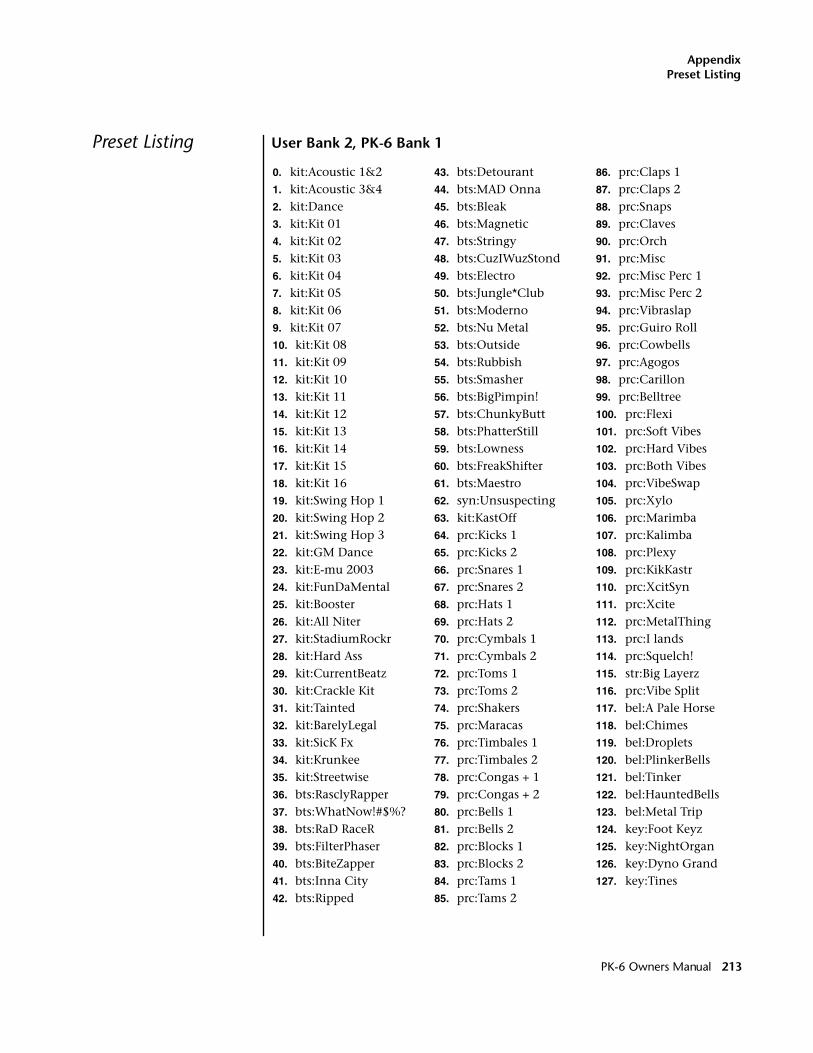
AppendixPreset Listing
Preset Listing User Bank 2, PK-6 Bank 1
0. kit:Acoustic 1&21. kit:Acoustic 3&42. kit:Dance3. kit:Kit 014. kit:Kit 025. kit:Kit 036. kit:Kit 047. kit:Kit 058. kit:Kit 069. kit:Kit 0710. kit:Kit 0811. kit:Kit 0912. kit:Kit 1013. kit:Kit 1114. kit:Kit 1215. kit:Kit 1316. kit:Kit 1417. kit:Kit 1518. kit:Kit 1619. kit:Swing Hop 120. kit:Swing Hop 221. kit:Swing Hop 322. kit:GM Dance23. kit:E-mu 200324. kit:FunDaMental25. kit:Booster26. kit:All Niter27. kit:StadiumRockr28. kit:Hard Ass29. kit:CurrentBeatz30. kit:Crackle Kit31. kit:Tainted32. kit:BarelyLegal33. kit:SicK Fx34. kit:Krunkee35. kit:Streetwise36. bts:RasclyRapper37. bts:WhatNow!#$%?38. bts:RaD RaceR39. bts:FilterPhaser40. bts:BiteZapper41. bts:Inna City42. bts:Ripped
43. bts:Detourant44. bts:MAD Onna45. bts:Bleak46. bts:Magnetic47. bts:Stringy48. bts:CuzIWuzStond49. bts:Electro50. bts:Jungle*Club51. bts:Moderno52. bts:Nu Metal53. bts:Outside54. bts:Rubbish55. bts:Smasher56. bts:BigPimpin!57. bts:ChunkyButt58. bts:PhatterStill59. bts:Lowness60. bts:FreakShifter61. bts:Maestro62. syn:Unsuspecting63. kit:KastOff64. prc:Kicks 165. prc:Kicks 266. prc:Snares 167. prc:Snares 268. prc:Hats 169. prc:Hats 270. prc:Cymbals 171. prc:Cymbals 272. prc:Toms 173. prc:Toms 274. prc:Shakers75. prc:Maracas76. prc:Timbales 177. prc:Timbales 278. prc:Congas + 179. prc:Congas + 280. prc:Bells 181. prc:Bells 282. prc:Blocks 183. prc:Blocks 284. prc:Tams 185. prc:Tams 2
86. prc:Claps 187. prc:Claps 288. prc:Snaps89. prc:Claves90. prc:Orch91. prc:Misc92. prc:Misc Perc 193. prc:Misc Perc 294. prc:Vibraslap95. prc:Guiro Roll96. prc:Cowbells97. prc:Agogos98. prc:Carillon99. prc:Belltree100. prc:Flexi101. prc:Soft Vibes102. prc:Hard Vibes103. prc:Both Vibes104. prc:VibeSwap105. prc:Xylo106. prc:Marimba107. prc:Kalimba108. prc:Plexy109. prc:KikKastr110. prc:XcitSyn111. prc:Xcite112. prc:MetalThing113. prc:I lands114. prc:Squelch!115. str:Big Layerz116. prc:Vibe Split117. bel:A Pale Horse118. bel:Chimes119. bel:Droplets120. bel:PlinkerBells121. bel:Tinker122. bel:HauntedBells123. bel:Metal Trip124. key:Foot Keyz125. key:NightOrgan126. key:Dyno Grand127. key:Tines
PK-6 Owners Manual 213
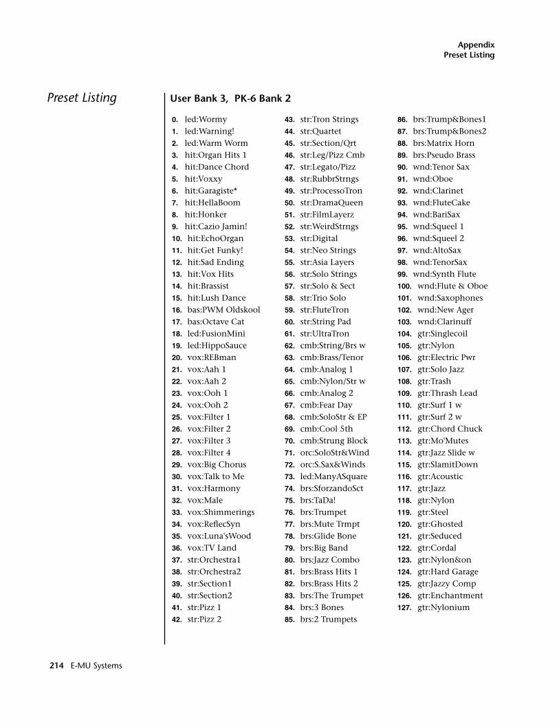
AppendixPreset Listing
Preset Listing User Bank 3, PK-6 Bank 2
0. led:Wormy1. led:Warning!2. led:Warm Worm3. hit:Organ Hits 14. hit:Dance Chord5. hit:Voxxy6. hit:Garagiste*7. hit:HellaBoom8. hit:Honker9. hit:Cazio Jamin!10. hit:EchoOrgan11. hit:Get Funky!12. hit:Sad Ending13. hit:Vox Hits14. hit:Brassist15. hit:Lush Dance16. bas:PWM Oldskool17. bas:Octave Cat18. led:FusionMini19. led:HippoSauce20. vox:REBman21. vox:Aah 122. vox:Aah 223. vox:Ooh 124. vox:Ooh 225. vox:Filter 126. vox:Filter 227. vox:Filter 328. vox:Filter 429. vox:Big Chorus30. vox:Talk to Me31. vox:Harmony32. vox:Male33. vox:Shimmerings34. vox:ReflecSyn35. vox:Luna'sWood36. vox:TV Land37. str:Orchestra138. str:Orchestra239. str:Section140. str:Section241. str:Pizz 142. str:Pizz 2
43. str:Tron Strings44. str:Quartet45. str:Section/Qrt46. str:Leg/Pizz Cmb47. str:Legato/Pizz48. str:RubbrStrngs49. str:ProcessoTron50. str:DramaQueen51. str:FilmLayerz52. str:WeirdStrngs53. str:Digital54. str:Neo Strings55. str:Asia Layers56. str:Solo Strings57. str:Solo & Sect58. str:Trio Solo59. str:FluteTron60. str:String Pad61. str:UltraTron62. cmb:String/Brs w63. cmb:Brass/Tenor64. cmb:Analog 165. cmb:Nylon/Str w66. cmb:Analog 267. cmb:Fear Day68. cmb:SoloStr & EP69. cmb:Cool 5th70. cmb:Strung Block71. orc:SoloStr&Wind72. orc:S.Sax&Winds73. led:ManyASquare74. brs:SforzandoSct75. brs:TaDa!76. brs:Trumpet77. brs:Mute Trmpt78. brs:Glide Bone79. brs:Big Band80. brs:Jazz Combo81. brs:Brass Hits 182. brs:Brass Hits 283. brs:The Trumpet84. brs:3 Bones85. brs:2 Trumpets
86. brs:Trump&Bones187. brs:Trump&Bones288. brs:Matrix Horn89. brs:Pseudo Brass90. wnd:Tenor Sax91. wnd:Oboe92. wnd:Clarinet93. wnd:FluteCake94. wnd:BariSax95. wnd:Squeel 196. wnd:Squeel 297. wnd:AltoSax98. wnd:TenorSax99. wnd:Synth Flute100. wnd:Flute & Oboe101. wnd:Saxophones102. wnd:New Ager103. wnd:Clarinuff104. gtr:Singlecoil105. gtr:Nylon106. gtr:Electric Pwr107. gtr:Solo Jazz108. gtr:Trash109. gtr:Thrash Lead110. gtr:Surf 1 w111. gtr:Surf 2 w112. gtr:Chord Chuck113. gtr:Mo'Mutes114. gtr:Jazz Slide w115. gtr:SlamitDown116. gtr:Acoustic117. gtr:Jazz118. gtr:Nylon119. gtr:Steel120. gtr:Ghosted121. gtr:Seduced122. gtr:Cordal123. gtr:Nylon&on124. gtr:Hard Garage125. gtr:Jazzy Comp126. gtr:Enchantment127. gtr:Nylonium
214 E-MU Systems
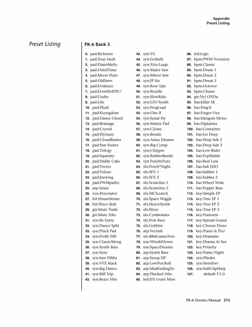
AppendixPreset Listing
Preset Listing PK-6 Bank 3
0. pad:Richness1. pad:Your Fault2. pad:PianoMeltz3. pad:OutofTime4. pad:Moon Flute5. pad:OldSaws6. pad:Evidence7. pad:EvenMoEPIC!8. pad:Under9. pad:Life10. pad:Phatt11. pad:Keyngdom12. pad:Dance Chord13. pad:Brassage14. pad:Crystal15. pad:Elysium16. pad:CloudBuster17. pad:Star Seeker18. pad:Trilogy19. pad:Squirmy20. pad:Paddy Cake21. pad:Vector22. pad:Velour23. pad:Jarreing24. pad:PWMpathy25. arp:Azian26. vox:Percolator27. hit:HouseStrum28. hit:Disco Stab29. gtr:Mute Trails30. gtr:Mute 5ths31. syn:Re Entry32. syn:Dance Split33. syn:Pluck Pad34. syn:Profit 50035. syn:ClassicMoog36. syn:Synth Bass37. syn:Sync38. syn:Saw Fifths39. syn:VFX Stack40. syn:Big Dance41. syn:Riff Trip42. syn:Brazz 5ths
43. syn:VS44. syn:Goliath45. syn:Xtra Large46. syn:Major Saw47. syn:Minor Saw48. syn:JP Six49. syn:Row Tate50. syn:Rezelle51. syn:SlowRide52. syn:LFO Synth53. syn:FrogLead54. syn:Ubu II55. syn:Serial Fly56. syn:Matrix Pad57. syn:CZone58. syn:Benda59. syn:Asian Dreams60. syn:Big Comp61. syn:Chipper62. syn:RubberBands63. syn:PeachyFuzz64. sfx:Porch*Night65. sfx:SFX 166. sfx:SFX 267. sfx:Scratches 168. sfx:Scratches 269. sfx:MCScratch70. sfx:Space Wiggle71. sfx:HeavySynth72. sfx:Slicer73. sfx:Cymbolater74. sfx:Post Razz75. sfx:Goblins76. arp:Vectrek77. sfx:8BitGameOver78. nse:WinditDown79. nse:SpaceDreams80. arp:Synth Bass81. arp:Syrup HP82. arp:LowPercRoll83. arp:MadEndingYo84. arp:Plucked 5ths85. led:DX Gone Mini
86. led:Lego87. bpm:PWM Voxation88. bpm:Classic89. bpm:Drum 190. bpm:Drum 291. bpm:Drum 392. bpm:Octover93. bpm:Chaser94. gtr:Nyl ONDa95. bas:Killer SE96. bas:Fing'd97. bas:Finger Oxx98. bas:Hangem Mono99. bas:Hiptainer100. bas:Container101. bas:Go Deep102. bas:Drop Sub 2103. bas:Drop Sub 3104. bas:Low Rider105. bas:PopSlidah106. bas:Real Low107. bas:Sub H2O108. bas:Subber 1109. bas:Subber 2110. bas:Wheel Wide111. bas:Pepper Bass112. key:Simple EP113. key:Tine EP 1114. key:Tine EP 2115. key:Tine EP 3116. key:Pianostic117. key:Spread Grand118. key:Chorus Dyno119. key:Piano & Pizz120. key:Dramatic121. key:Drama At Sea122. key:Polarity123. key:Piano Night124. syn:Pliedes125. syn:Sensitive126. syn:SoftClipHarp127. default V1.0
PK-6 Owners Manual 215
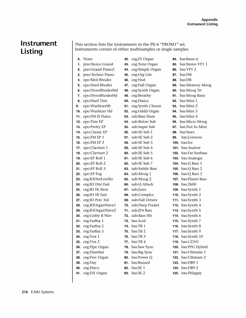
AppendixInstrument Listing
Instrument Listing
This section lists the instruments in the PK-6 “PROM1” set.Instruments consist of either multisamples or single samples.
0. None 1. pno:Stereo Grand2. pno:Grand Piano23. pno:Techno Piano4. epo:Med Rhodes5. epo:Hard Rhodes6. epo:DynoRhodesMd7. epo:DynoRhodesHd8. epo:Hard Tine
9. epo:WurlitzerSft10. epo:Wurlitzer Hd11. epo:FM El Piano 12. epo:Tine EP13. epo:Pretty EP14. epo:Classic EP15. epo:FM EP 116. epo:FM EP 217. epo:Clavinet 118. epo:Clavinet 219. epo:EP Roll 120. epo:EP Roll 221. epo:EP Roll 322. epo:EP Fog23. org:B3DistLowSlo24. org:B3 Dist Fast25. org:B3 Hi Slow26. org:B3 Hi Fast27. org:B3 Perc 3rd 28. org:B3OrganWave129. org:B3OrganWave230. org:Gritty B Wav31. org:Farfisa 132. org:Farfisa 233. org:Farfisa 334. org:Vox 135. org:Vox 236. org:Pipe Organ 37. org:Drawbar38. org:Perc Organ39. org:Day40. org:Disco 41. org:DX Organ
42. org:JX Organ43. org:Tone Organ44. org:Simple Organ45. org:Org Lite46. org:Nod47. org:Full Organ48. org:Synth Organ 49. org:Breathy50. org:Dance51. org:Synth Cheeze52. org:Oddd Organ53. sub:Bass Hum54. sub:Below Sub55. sub:Super Sub56. sub:SE Sub 157. sub:SE Sub 258. sub:SE Sub 359. sub:SE Sub 460. sub:SE Sub 561. sub:SE Sub 662. sub:SE Sub 763. sub:Subtle Bass 64. sub:Moog 165. sub:Moog 266. sub:Q Attack67. sub:Juno68. sub:Complex69. sub:Full Octave 70. sub:Deep Pocket 71. sub:JP4 Bass72. sub:Bass Hit73. bas:Acid74. bas:TB 175. bas:TB 276. bas:TB 377. bas:TB 478. bas:Saw Sync79. bas:Big Sync80. bas:Power Q81. bas:Buzzed82. bas:SE 183. bas:SE 2
84. bas:Basss ic85. bas:Stereo VP1 186. bas:VP1 287. bas:FM88. bas:DB89. bas:Memory Moog90. bas:Moog Tri91. bas:Moog Basic92. bas:Mini 193. bas:Mini 294. bas:Mini 395. bas:Mini 496. bas:Micro Moog97. bas:Not So Mini 98. bas:Sawz99. bas:Lowness100. bas:Ice 101. bas:Analow102. bas:Fat Sunbass 103. bas:Analogic104. bas:Q Bass 1105. bas:Q Bass 2106. bas:Q Bass 3107. bas:Planet Bass 108. bas:2600109. bas:Synth 1110. bas:Synth 2111. bas:Synth 3112. bas:Synth 4113. bas:Synth 5114. bas:Synth 6115. bas:Synth 7116. bas:Synth 8117. bas:Synth 9118. bas:Synth 10119. bas:CZ101120. bas:PPG Hybrid121. bas:Ultimate 1122. bas:Ultimate 2123. bas:DB9 1124. bas:DB9 2125. bas:Phlappy
216 E-MU Systems
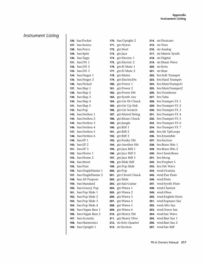
AppendixInstrument Listing
Instrument Listing126. bas:Pocket127. bas:Sonics128. bas:Perco129. bas:Spitt130. bas:Tapp131. bas:DX 1132. bas:DX 2133. bas:DX 3134. bas:Finger 1135. bas:Finger 2136. bas:Picked137. bas:Slap 1138. bas:Slap 2139. bas:Slap 3140. bas:Slap 4141. bas:Slap 5142. bas:Pop 143. bas:Fretless 1144. bas:Fretless 2145. bas:Fretless 3146. bas:Fretless 4147. bas:Fretless 5148. bas:Fretless 6149. bas:EP 1150. bas:EP 2151. bas:EP 3152. bas:Home 1153. bas:Home 2154. bas:Street155. bas:Pure156. bas:Fing&Harms 1157. bas:Fing&Harms 2158. bas:All Purpose 159. bas:Standard160. bas:Gruzzy Pop161. bas:Pop Slide 1 162. bas:Pop Slide 2 163. bas:Pop Slide 3 164. bas:Pop Slide 4 165. bas:Organ Bass 1166. bas:Organ Bass 2167. bas:Acoustic168. bas:Harmonics169. bas:Upright 1
170. bas:Upright 2171. gtr:Nylon172. gtr:Steel173. gtr:Jazz174. gtr:Electric 1175. gtr:Electric 2176. gtr:El Mute 1177. gtr:El Mute 2178. gtr:Mutes179. gtr:ElectricDis 180. gtr:Power 1181. gtr:Power 2182. gtr:Power Hit183. gtr:Synth Axe184. gtr:Gtr Hi Chuck185. gtr:Gtr Up Strk 186. gtr:Gtr Scratch 187. gtr:Muted String188. gtr:Klean Chuck 189. gtr:Jangle190. gtr:Riff 1191. gtr:Riff 2192. gtr:Riff 3193. gtr:Funky Hit194. gtr:Another Hit 195. gtr:Jazz Riff 1 196. gtr:Jazz Riff 2 197. gtr:Jazz Riff 3 198. gtr:Slide Riff199. gtr:Pop Slide200. gtr:Pop 201. gtr:Chord Chuck 202. gtr:Slide203. gtr:Sad Guitar204. gtr:Wawa 1205. gtr:Wawa 2206. gtr:Wawa 3207. gtr:Wawa 4208. gtr:Wawa 5209. gtr:Wawa 6210. gtr:Heavy Hit211. gtr:Heavy Dive212. str:Solo Quartet213. str:Section
214. str:Pizzicato215. str:Tron216. str:Analog217. str:Matrix Synth218. str:Digital219. str:Sham Wave220. str:Koto221. str:Sitar222. brs:Soft Trumpet223. brs:Hard Trumpet224. brs:MuteTrumpet1225. brs:MuteTrumpet2226. brs:Trombone227. brs:Tuba228. brs:Trumpet FX 1229. brs:Trumpet FX 2230. brs:Trumpet FX 3231. brs:Trumpet FX 4232. brs:Trumpet FX 5233. brs:Trumpet FX 6234. brs:Trumpet FX 7235. brs:Alt TptLoops236. brs:Ensemble237. brs:Section238. brs:Brass Hits 1239. brs:Brass Hits 2240. brs:ClassicBrass241. brs:Moog242. brs:Prophet 5243. brs:5th Wave244. wnd:Ocarina245. wnd:Pan Flute246. wnd:Flute247. wnd:Synth Flute 248. wnd:Clarinet249. wnd:Oboe250. wnd:English Horn251. wnd:Soprano Sax 252. wnd:Alto Sax253. wnd:Tenor Sax254. wnd:Sax Wave255. wnd:Bari Sax 1256. wnd:Bari Sax 2257. wnd:Sax Riff
PK-6 Owners Manual 217
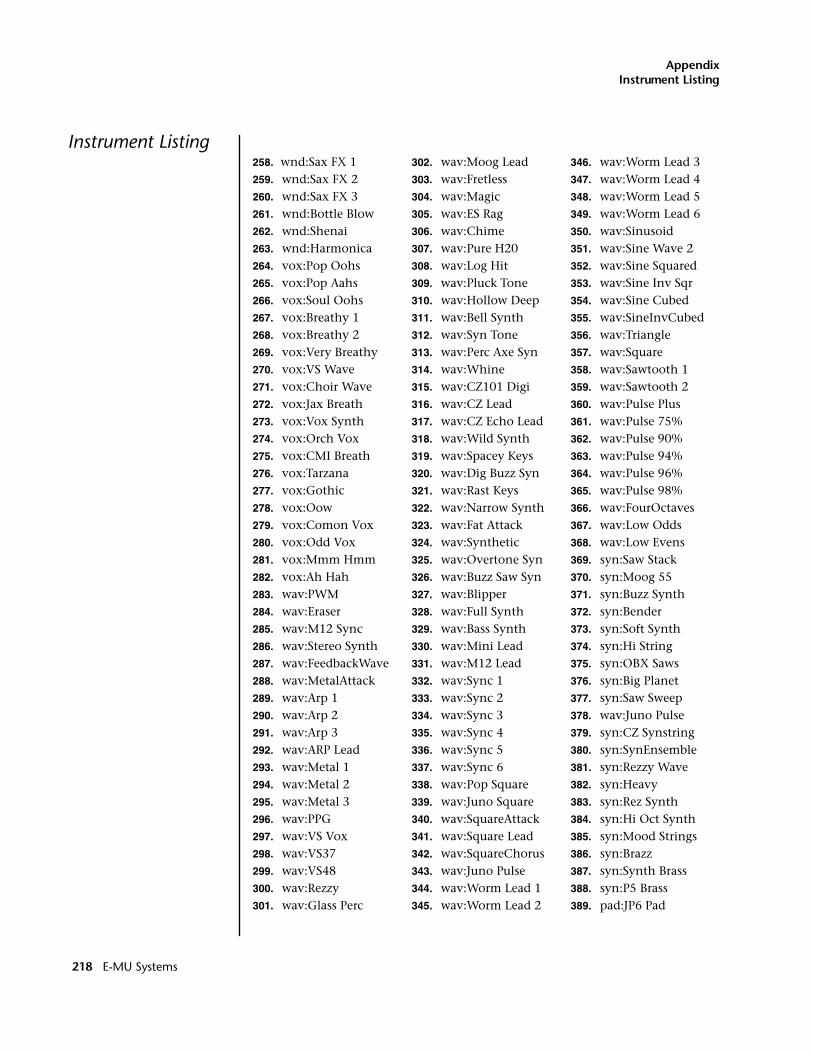
AppendixInstrument Listing
Instrument Listing258. wnd:Sax FX 1259. wnd:Sax FX 2260. wnd:Sax FX 3261. wnd:Bottle Blow 262. wnd:Shenai263. wnd:Harmonica264. vox:Pop Oohs265. vox:Pop Aahs266. vox:Soul Oohs267. vox:Breathy 1268. vox:Breathy 2269. vox:Very Breathy270. vox:VS Wave271. vox:Choir Wave272. vox:Jax Breath273. vox:Vox Synth274. vox:Orch Vox275. vox:CMI Breath276. vox:Tarzana277. vox:Gothic278. vox:Oow 279. vox:Comon Vox280. vox:Odd Vox281. vox:Mmm Hmm282. vox:Ah Hah283. wav:PWM284. wav:Eraser285. wav:M12 Sync286. wav:Stereo Synth287. wav:FeedbackWave288. wav:MetalAttack 289. wav:Arp 1290. wav:Arp 2291. wav:Arp 3292. wav:ARP Lead293. wav:Metal 1294. wav:Metal 2295. wav:Metal 3296. wav:PPG 297. wav:VS Vox298. wav:VS37299. wav:VS48300. wav:Rezzy301. wav:Glass Perc
302. wav:Moog Lead303. wav:Fretless304. wav:Magic305. wav:ES Rag306. wav:Chime307. wav:Pure H20308. wav:Log Hit309. wav:Pluck Tone310. wav:Hollow Deep311. wav:Bell Synth312. wav:Syn Tone313. wav:Perc Axe Syn314. wav:Whine315. wav:CZ101 Digi316. wav:CZ Lead317. wav:CZ Echo Lead318. wav:Wild Synth319. wav:Spacey Keys320. wav:Dig Buzz Syn321. wav:Rast Keys322. wav:Narrow Synth323. wav:Fat Attack324. wav:Synthetic325. wav:Overtone Syn326. wav:Buzz Saw Syn327. wav:Blipper328. wav:Full Synth329. wav:Bass Synth330. wav:Mini Lead331. wav:M12 Lead332. wav:Sync 1333. wav:Sync 2334. wav:Sync 3335. wav:Sync 4336. wav:Sync 5337. wav:Sync 6338. wav:Pop Square339. wav:Juno Square340. wav:SquareAttack341. wav:Square Lead 342. wav:SquareChorus343. wav:Juno Pulse344. wav:Worm Lead 1345. wav:Worm Lead 2
346. wav:Worm Lead 3347. wav:Worm Lead 4348. wav:Worm Lead 5349. wav:Worm Lead 6350. wav:Sinusoid351. wav:Sine Wave 2352. wav:Sine Squared353. wav:Sine Inv Sqr354. wav:Sine Cubed355. wav:SineInvCubed356. wav:Triangle357. wav:Square358. wav:Sawtooth 1359. wav:Sawtooth 2360. wav:Pulse Plus361. wav:Pulse 75%362. wav:Pulse 90%363. wav:Pulse 94%364. wav:Pulse 96%365. wav:Pulse 98%366. wav:FourOctaves367. wav:Low Odds368. wav:Low Evens369. syn:Saw Stack370. syn:Moog 55371. syn:Buzz Synth372. syn:Bender373. syn:Soft Synth374. syn:Hi String375. syn:OBX Saws376. syn:Big Planet377. syn:Saw Sweep378. wav:Juno Pulse379. syn:CZ Synstring380. syn:SynEnsemble 381. syn:Rezzy Wave382. syn:Heavy383. syn:Rez Synth384. syn:Hi Oct Synth385. syn:Mood Strings386. syn:Brazz387. syn:Synth Brass 388. syn:P5 Brass389. pad:JP6 Pad
218 E-MU Systems
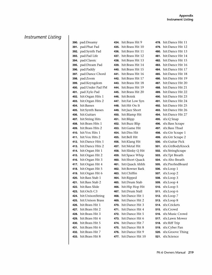
AppendixInstrument Listing
Instrument Listing390. pad:Dreamy391. pad:Phat Pad392. pad:Synth Pad393. pad:Pad Life394. pad:Classic395. pad:Dream Pad396. pad:Paddy397. pad:Dance Chord398. pad:Zoom399. pad:Keyngdom400. pad:Under Pad FM401. pad:Xylo Pad402. hit:Organ Hits 1403. hit:Organ Hits 2404. hit:Basses405. hit:Synth Basses406. hit:Guitars407. hit:String Hits 408. hit:Brass Hits 1409. hit:Brass Hits 2410. hit:Vox Hits 1411. hit:Vox Hits 2412. hit:Dance Hits 1413. hit:Dance Hits 2414. hit:Organ Hit 1415. hit:Organ Hit 2416. hit:Organ Hit 3417. hit:Organ Hit 4418. hit:Organ Hit 5419. hit:Organ Hit 6420. hit:Bass Stab 1421. hit:Bass Stab 2422. hit:Bass Slide423. hit:Orch C3424. hit:UnisonString425. hit:Unison Brass426. hit:Brass Hit 1427. hit:Brass Hit 2428. hit:Brass Hit 3429. hit:Brass Hit 4430. hit:Brass Hit 5431. hit:Brass Hit 6432. hit:Brass Hit 7433. hit:Brass Hit 8
434. hit:Brass Hit 9435. hit:Brass Hit 10436. hit:Brass Hit 11437. hit:Brass Hit 12438. hit:Brass Hit 13439. hit:Brass Hit 14440. hit:Brass Hit 15441. hit:Brass Hit 16442. hit:Brass Hit 17443. hit:Brass Hit 18444. hit:Brass Hit 19445. hit:Brass Hit 20446. hit:Boink447. hit:Fat Low Syn 448. hit:Hit On It449. hit:Jazz Short450. hit:Blamp Hit451. hit:Blipp452. hit:Buzz Blip453. hit:Game Hit454. hit:Diss Hit455. hit:Bell Hit456. hit:Klang Hit457. hit:Metal Hit458. hit:Slinky Q Hit459. hit:Space Whip460. hit:Short Quack461. hit:Quack Ahhh462. hit:Bowser Bark 463. hit:Chiffin464. hit:Ripped465. hit:Drum Stab466. hit:Hip Hop Hit 467. hit:Drum Stall468. hit:Dance Hit 1469. hit:Dance Hit 2470. hit:Dance Hit 3471. hit:Dance Hit 4472. hit:Dance Hit 5473. hit:Dance Hit 6474. hit:Dance Hit 7475. hit:Dance Hit 8476. hit:Dance Hit 9477. hit:Dance Hit 10
478. hit:Dance Hit 11479. hit:Dance Hit 12480. hit:Dance Hit 13481. hit:Dance Hit 14482. hit:Dance Hit 15483. hit:Dance Hit 16484. hit:Dance Hit 17485. hit:Dance Hit 18486. hit:Dance Hit 19487. hit:Dance Hit 20488. hit:Dance Hit 21489. hit:Dance Hit 22490. hit:Dance Hit 23491. hit:Dance Hit 24492. hit:Dance Hit 25493. hit:Dance Hit 26494. hit:Dance Hit 27495. sfx:Q Snap496. sfx:Bass Scrape497. sfx:Bass Thud498. sfx:Gtr Scrape 1499. sfx:Gtr Scrape 2500. sfx:Guitar Pick 501. sfx:GtrBodyKnock502. sfx:StringScrape503. sfx:Tpt Breath504. sfx:Alto Breath 505. sfx:PnoSndBoard 506. sfx:Loop 1507. sfx:Loop 2508. sfx:Loop 3509. sfx:Loop 4510. sfx:Loop 5511. sfx:Loop 6512. sfx:Loop 7513. sfx:Loop 8514. sfx:Crickets515. sfx:Crowd516. sfx:Music Crowd 517. sfx:Lawn Mower518. sfx:Riff Trip519. sfx:Cyber Pan520. sfx:Groove Thing521. sfx:Science
PK-6 Owners Manual 219
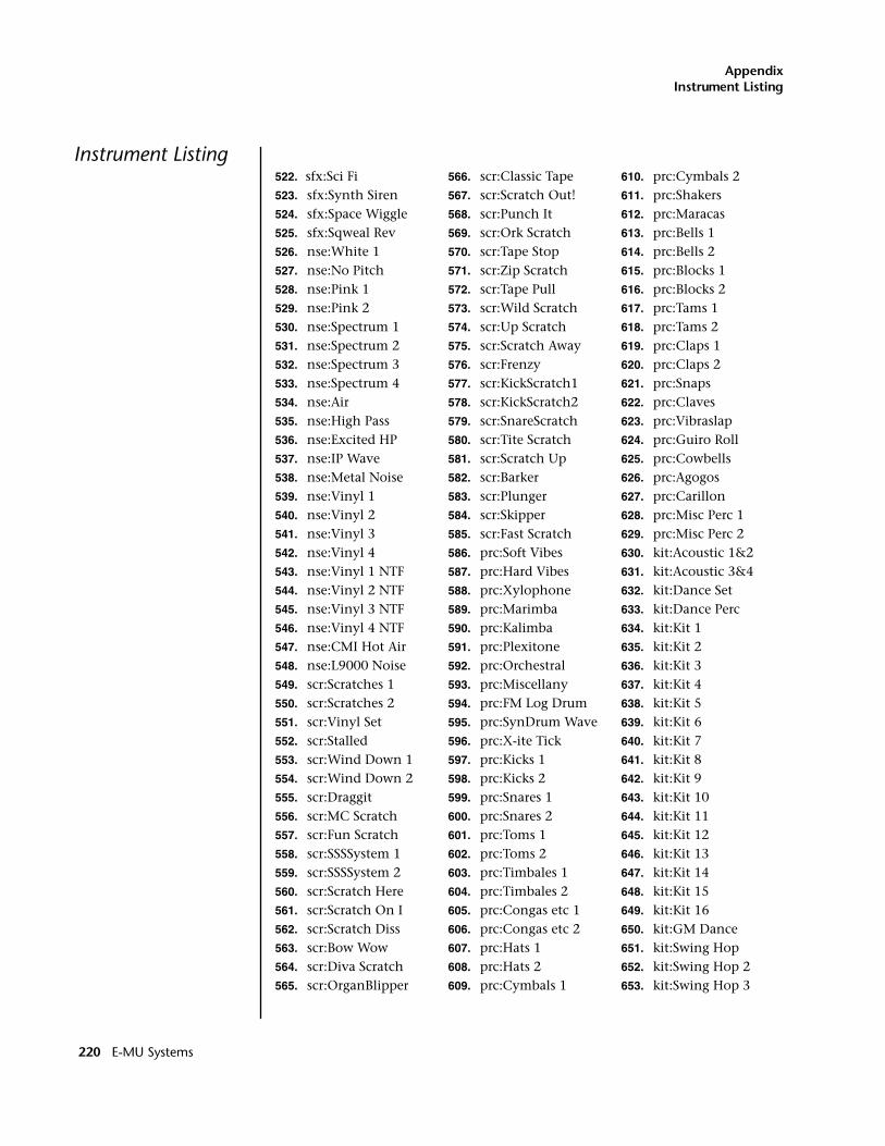
AppendixInstrument Listing
Instrument Listing522. sfx:Sci Fi523. sfx:Synth Siren524. sfx:Space Wiggle525. sfx:Sqweal Rev526. nse:White 1527. nse:No Pitch528. nse:Pink 1529. nse:Pink 2530. nse:Spectrum 1531. nse:Spectrum 2532. nse:Spectrum 3533. nse:Spectrum 4534. nse:Air 535. nse:High Pass536. nse:Excited HP537. nse:IP Wave538. nse:Metal Noise 539. nse:Vinyl 1540. nse:Vinyl 2541. nse:Vinyl 3542. nse:Vinyl 4543. nse:Vinyl 1 NTF544. nse:Vinyl 2 NTF545. nse:Vinyl 3 NTF546. nse:Vinyl 4 NTF547. nse:CMI Hot Air548. nse:L9000 Noise549. scr:Scratches 1550. scr:Scratches 2551. scr:Vinyl Set552. scr:Stalled553. scr:Wind Down 1554. scr:Wind Down 2555. scr:Draggit556. scr:MC Scratch557. scr:Fun Scratch558. scr:SSSSystem 1 559. scr:SSSSystem 2 560. scr:Scratch Here561. scr:Scratch On I562. scr:Scratch Diss563. scr:Bow Wow564. scr:Diva Scratch565. scr:OrganBlipper
566. scr:Classic Tape567. scr:Scratch Out!568. scr:Punch It569. scr:Ork Scratch 570. scr:Tape Stop571. scr:Zip Scratch 572. scr:Tape Pull573. scr:Wild Scratch574. scr:Up Scratch575. scr:Scratch Away576. scr:Frenzy577. scr:KickScratch1578. scr:KickScratch2579. scr:SnareScratch580. scr:Tite Scratch581. scr:Scratch Up582. scr:Barker583. scr:Plunger584. scr:Skipper585. scr:Fast Scratch586. prc:Soft Vibes587. prc:Hard Vibes588. prc:Xylophone589. prc:Marimba590. prc:Kalimba591. prc:Plexitone592. prc:Orchestral593. prc:Miscellany594. prc:FM Log Drum595. prc:SynDrum Wave596. prc:X-ite Tick597. prc:Kicks 1598. prc:Kicks 2599. prc:Snares 1600. prc:Snares 2601. prc:Toms 1602. prc:Toms 2603. prc:Timbales 1604. prc:Timbales 2605. prc:Congas etc 1606. prc:Congas etc 2607. prc:Hats 1608. prc:Hats 2609. prc:Cymbals 1
610. prc:Cymbals 2611. prc:Shakers612. prc:Maracas613. prc:Bells 1614. prc:Bells 2615. prc:Blocks 1616. prc:Blocks 2617. prc:Tams 1618. prc:Tams 2619. prc:Claps 1620. prc:Claps 2621. prc:Snaps622. prc:Claves623. prc:Vibraslap624. prc:Guiro Roll625. prc:Cowbells626. prc:Agogos627. prc:Carillon628. prc:Misc Perc 1629. prc:Misc Perc 2630. kit:Acoustic 1&2631. kit:Acoustic 3&4632. kit:Dance Set633. kit:Dance Perc634. kit:Kit 1635. kit:Kit 2636. kit:Kit 3637. kit:Kit 4638. kit:Kit 5639. kit:Kit 6640. kit:Kit 7641. kit:Kit 8642. kit:Kit 9643. kit:Kit 10644. kit:Kit 11645. kit:Kit 12646. kit:Kit 13647. kit:Kit 14648. kit:Kit 15649. kit:Kit 16650. kit:GM Dance651. kit:Swing Hop652. kit:Swing Hop 2653. kit:Swing Hop 3
220 E-MU Systems
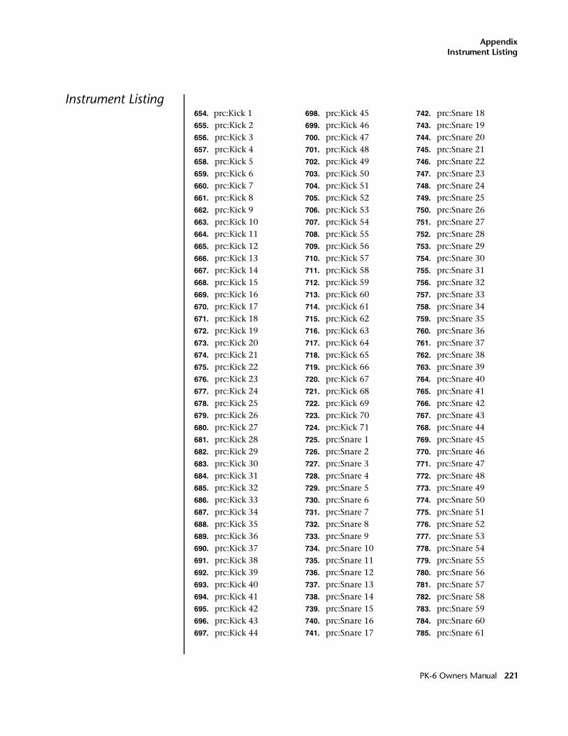
AppendixInstrument Listing
Instrument Listing654. prc:Kick 1 655. prc:Kick 2656. prc:Kick 3657. prc:Kick 4658. prc:Kick 5659. prc:Kick 6660. prc:Kick 7661. prc:Kick 8662. prc:Kick 9663. prc:Kick 10664. prc:Kick 11665. prc:Kick 12666. prc:Kick 13667. prc:Kick 14668. prc:Kick 15669. prc:Kick 16670. prc:Kick 17671. prc:Kick 18672. prc:Kick 19673. prc:Kick 20674. prc:Kick 21675. prc:Kick 22676. prc:Kick 23677. prc:Kick 24678. prc:Kick 25679. prc:Kick 26680. prc:Kick 27681. prc:Kick 28682. prc:Kick 29683. prc:Kick 30684. prc:Kick 31685. prc:Kick 32686. prc:Kick 33687. prc:Kick 34688. prc:Kick 35689. prc:Kick 36690. prc:Kick 37691. prc:Kick 38692. prc:Kick 39693. prc:Kick 40694. prc:Kick 41695. prc:Kick 42696. prc:Kick 43697. prc:Kick 44
698. prc:Kick 45699. prc:Kick 46700. prc:Kick 47701. prc:Kick 48702. prc:Kick 49703. prc:Kick 50704. prc:Kick 51705. prc:Kick 52706. prc:Kick 53707. prc:Kick 54708. prc:Kick 55709. prc:Kick 56710. prc:Kick 57711. prc:Kick 58712. prc:Kick 59713. prc:Kick 60714. prc:Kick 61715. prc:Kick 62716. prc:Kick 63717. prc:Kick 64718. prc:Kick 65719. prc:Kick 66720. prc:Kick 67721. prc:Kick 68722. prc:Kick 69723. prc:Kick 70724. prc:Kick 71725. prc:Snare 1726. prc:Snare 2727. prc:Snare 3728. prc:Snare 4729. prc:Snare 5730. prc:Snare 6731. prc:Snare 7732. prc:Snare 8733. prc:Snare 9734. prc:Snare 10735. prc:Snare 11736. prc:Snare 12737. prc:Snare 13738. prc:Snare 14739. prc:Snare 15740. prc:Snare 16741. prc:Snare 17
742. prc:Snare 18743. prc:Snare 19744. prc:Snare 20745. prc:Snare 21746. prc:Snare 22747. prc:Snare 23748. prc:Snare 24749. prc:Snare 25750. prc:Snare 26751. prc:Snare 27752. prc:Snare 28753. prc:Snare 29754. prc:Snare 30755. prc:Snare 31756. prc:Snare 32757. prc:Snare 33758. prc:Snare 34759. prc:Snare 35760. prc:Snare 36761. prc:Snare 37762. prc:Snare 38763. prc:Snare 39764. prc:Snare 40765. prc:Snare 41766. prc:Snare 42767. prc:Snare 43768. prc:Snare 44769. prc:Snare 45770. prc:Snare 46771. prc:Snare 47772. prc:Snare 48773. prc:Snare 49774. prc:Snare 50775. prc:Snare 51776. prc:Snare 52777. prc:Snare 53778. prc:Snare 54779. prc:Snare 55780. prc:Snare 56781. prc:Snare 57782. prc:Snare 58783. prc:Snare 59784. prc:Snare 60785. prc:Snare 61
PK-6 Owners Manual 221
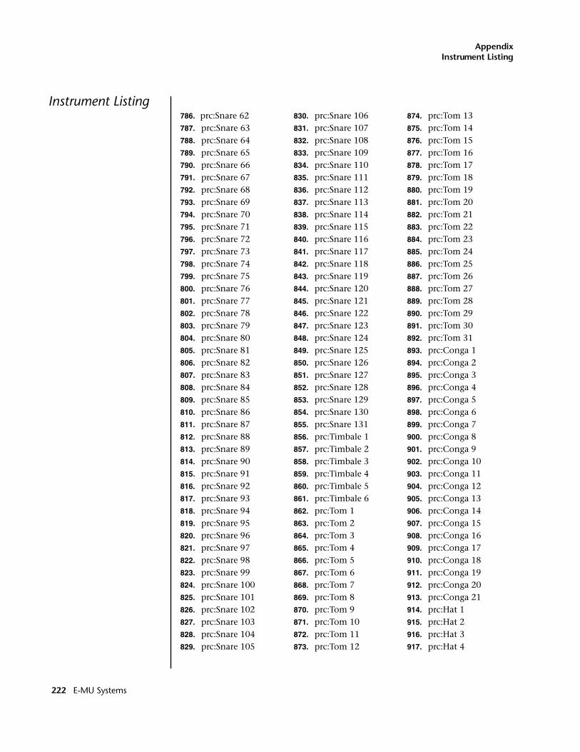
AppendixInstrument Listing
Instrument Listing786. prc:Snare 62787. prc:Snare 63788. prc:Snare 64789. prc:Snare 65790. prc:Snare 66791. prc:Snare 67792. prc:Snare 68793. prc:Snare 69794. prc:Snare 70795. prc:Snare 71796. prc:Snare 72797. prc:Snare 73798. prc:Snare 74799. prc:Snare 75800. prc:Snare 76801. prc:Snare 77802. prc:Snare 78803. prc:Snare 79804. prc:Snare 80805. prc:Snare 81806. prc:Snare 82807. prc:Snare 83808. prc:Snare 84809. prc:Snare 85810. prc:Snare 86811. prc:Snare 87812. prc:Snare 88813. prc:Snare 89814. prc:Snare 90815. prc:Snare 91816. prc:Snare 92817. prc:Snare 93818. prc:Snare 94819. prc:Snare 95820. prc:Snare 96821. prc:Snare 97822. prc:Snare 98823. prc:Snare 99824. prc:Snare 100825. prc:Snare 101826. prc:Snare 102827. prc:Snare 103828. prc:Snare 104829. prc:Snare 105
830. prc:Snare 106831. prc:Snare 107832. prc:Snare 108833. prc:Snare 109834. prc:Snare 110835. prc:Snare 111836. prc:Snare 112837. prc:Snare 113838. prc:Snare 114839. prc:Snare 115840. prc:Snare 116841. prc:Snare 117842. prc:Snare 118843. prc:Snare 119844. prc:Snare 120845. prc:Snare 121846. prc:Snare 122847. prc:Snare 123848. prc:Snare 124849. prc:Snare 125850. prc:Snare 126851. prc:Snare 127852. prc:Snare 128853. prc:Snare 129854. prc:Snare 130855. prc:Snare 131856. prc:Timbale 1857. prc:Timbale 2858. prc:Timbale 3859. prc:Timbale 4860. prc:Timbale 5861. prc:Timbale 6862. prc:Tom 1863. prc:Tom 2864. prc:Tom 3865. prc:Tom 4866. prc:Tom 5867. prc:Tom 6868. prc:Tom 7869. prc:Tom 8870. prc:Tom 9871. prc:Tom 10872. prc:Tom 11873. prc:Tom 12
874. prc:Tom 13875. prc:Tom 14876. prc:Tom 15877. prc:Tom 16878. prc:Tom 17879. prc:Tom 18880. prc:Tom 19881. prc:Tom 20882. prc:Tom 21883. prc:Tom 22884. prc:Tom 23885. prc:Tom 24886. prc:Tom 25887. prc:Tom 26888. prc:Tom 27889. prc:Tom 28890. prc:Tom 29891. prc:Tom 30892. prc:Tom 31893. prc:Conga 1894. prc:Conga 2895. prc:Conga 3896. prc:Conga 4897. prc:Conga 5898. prc:Conga 6899. prc:Conga 7900. prc:Conga 8901. prc:Conga 9902. prc:Conga 10903. prc:Conga 11904. prc:Conga 12905. prc:Conga 13906. prc:Conga 14907. prc:Conga 15908. prc:Conga 16909. prc:Conga 17910. prc:Conga 18911. prc:Conga 19912. prc:Conga 20913. prc:Conga 21914. prc:Hat 1915. prc:Hat 2916. prc:Hat 3917. prc:Hat 4
222 E-MU Systems
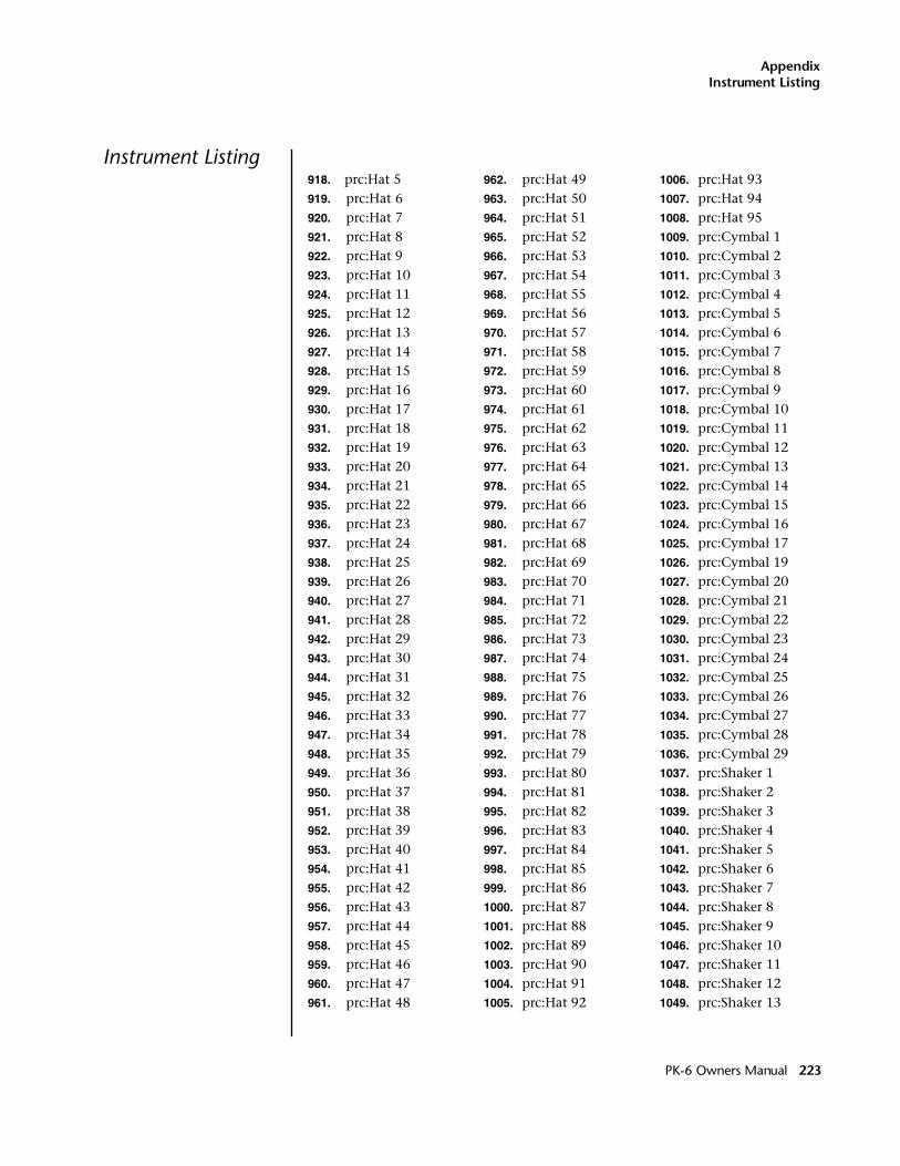
AppendixInstrument Listing
Instrument Listing918. prc:Hat 5919. prc:Hat 6920. prc:Hat 7921. prc:Hat 8922. prc:Hat 9923. prc:Hat 10924. prc:Hat 11925. prc:Hat 12926. prc:Hat 13927. prc:Hat 14928. prc:Hat 15929. prc:Hat 16930. prc:Hat 17931. prc:Hat 18932. prc:Hat 19933. prc:Hat 20934. prc:Hat 21935. prc:Hat 22936. prc:Hat 23937. prc:Hat 24938. prc:Hat 25939. prc:Hat 26940. prc:Hat 27941. prc:Hat 28942. prc:Hat 29943. prc:Hat 30944. prc:Hat 31945. prc:Hat 32946. prc:Hat 33947. prc:Hat 34948. prc:Hat 35949. prc:Hat 36950. prc:Hat 37951. prc:Hat 38952. prc:Hat 39953. prc:Hat 40954. prc:Hat 41955. prc:Hat 42956. prc:Hat 43957. prc:Hat 44958. prc:Hat 45959. prc:Hat 46960. prc:Hat 47961. prc:Hat 48
962. prc:Hat 49963. prc:Hat 50964. prc:Hat 51965. prc:Hat 52966. prc:Hat 53967. prc:Hat 54968. prc:Hat 55969. prc:Hat 56970. prc:Hat 57971. prc:Hat 58972. prc:Hat 59973. prc:Hat 60974. prc:Hat 61975. prc:Hat 62976. prc:Hat 63977. prc:Hat 64978. prc:Hat 65979. prc:Hat 66980. prc:Hat 67981. prc:Hat 68982. prc:Hat 69983. prc:Hat 70984. prc:Hat 71985. prc:Hat 72986. prc:Hat 73987. prc:Hat 74988. prc:Hat 75989. prc:Hat 76990. prc:Hat 77991. prc:Hat 78992. prc:Hat 79993. prc:Hat 80994. prc:Hat 81995. prc:Hat 82996. prc:Hat 83997. prc:Hat 84998. prc:Hat 85999. prc:Hat 861000. prc:Hat 871001. prc:Hat 881002. prc:Hat 891003. prc:Hat 901004. prc:Hat 911005. prc:Hat 92
1006. prc:Hat 931007. prc:Hat 941008. prc:Hat 951009. prc:Cymbal 11010. prc:Cymbal 21011. prc:Cymbal 31012. prc:Cymbal 41013. prc:Cymbal 51014. prc:Cymbal 61015. prc:Cymbal 71016. prc:Cymbal 81017. prc:Cymbal 91018. prc:Cymbal 101019. prc:Cymbal 111020. prc:Cymbal 121021. prc:Cymbal 131022. prc:Cymbal 141023. prc:Cymbal 151024. prc:Cymbal 161025. prc:Cymbal 171026. prc:Cymbal 191027. prc:Cymbal 201028. prc:Cymbal 211029. prc:Cymbal 221030. prc:Cymbal 231031. prc:Cymbal 241032. prc:Cymbal 251033. prc:Cymbal 261034. prc:Cymbal 271035. prc:Cymbal 281036. prc:Cymbal 291037. prc:Shaker 11038. prc:Shaker 21039. prc:Shaker 31040. prc:Shaker 41041. prc:Shaker 51042. prc:Shaker 61043. prc:Shaker 71044. prc:Shaker 81045. prc:Shaker 91046. prc:Shaker 101047. prc:Shaker 111048. prc:Shaker 121049. prc:Shaker 13
PK-6 Owners Manual 223
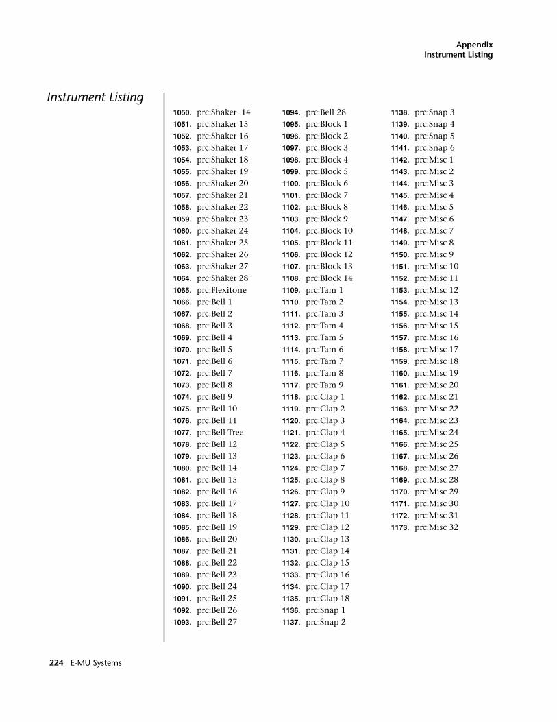
AppendixInstrument Listing
Instrument Listing1050. prc:Shaker 141051. prc:Shaker 151052. prc:Shaker 161053. prc:Shaker 171054. prc:Shaker 181055. prc:Shaker 191056. prc:Shaker 201057. prc:Shaker 211058. prc:Shaker 221059. prc:Shaker 231060. prc:Shaker 241061. prc:Shaker 251062. prc:Shaker 261063. prc:Shaker 271064. prc:Shaker 281065. prc:Flexitone1066. prc:Bell 11067. prc:Bell 21068. prc:Bell 31069. prc:Bell 41070. prc:Bell 51071. prc:Bell 61072. prc:Bell 71073. prc:Bell 81074. prc:Bell 91075. prc:Bell 101076. prc:Bell 111077. prc:Bell Tree1078. prc:Bell 121079. prc:Bell 131080. prc:Bell 141081. prc:Bell 151082. prc:Bell 161083. prc:Bell 171084. prc:Bell 181085. prc:Bell 191086. prc:Bell 201087. prc:Bell 211088. prc:Bell 221089. prc:Bell 231090. prc:Bell 241091. prc:Bell 251092. prc:Bell 261093. prc:Bell 27
1094. prc:Bell 281095. prc:Block 11096. prc:Block 21097. prc:Block 31098. prc:Block 41099. prc:Block 51100. prc:Block 61101. prc:Block 71102. prc:Block 81103. prc:Block 91104. prc:Block 101105. prc:Block 111106. prc:Block 121107. prc:Block 131108. prc:Block 141109. prc:Tam 11110. prc:Tam 21111. prc:Tam 31112. prc:Tam 41113. prc:Tam 51114. prc:Tam 61115. prc:Tam 71116. prc:Tam 81117. prc:Tam 91118. prc:Clap 11119. prc:Clap 21120. prc:Clap 31121. prc:Clap 41122. prc:Clap 51123. prc:Clap 61124. prc:Clap 71125. prc:Clap 81126. prc:Clap 91127. prc:Clap 101128. prc:Clap 111129. prc:Clap 121130. prc:Clap 131131. prc:Clap 141132. prc:Clap 151133. prc:Clap 161134. prc:Clap 171135. prc:Clap 181136. prc:Snap 11137. prc:Snap 2
1138. prc:Snap 31139. prc:Snap 41140. prc:Snap 51141. prc:Snap 61142. prc:Misc 11143. prc:Misc 21144. prc:Misc 31145. prc:Misc 41146. prc:Misc 51147. prc:Misc 61148. prc:Misc 71149. prc:Misc 81150. prc:Misc 91151. prc:Misc 101152. prc:Misc 111153. prc:Misc 121154. prc:Misc 131155. prc:Misc 141156. prc:Misc 151157. prc:Misc 161158. prc:Misc 171159. prc:Misc 181160. prc:Misc 191161. prc:Misc 201162. prc:Misc 211163. prc:Misc 221164. prc:Misc 231165. prc:Misc 241166. prc:Misc 251167. prc:Misc 261168. prc:Misc 271169. prc:Misc 281170. prc:Misc 291171. prc:Misc 301172. prc:Misc 311173. prc:Misc 32
224 E-MU Systems
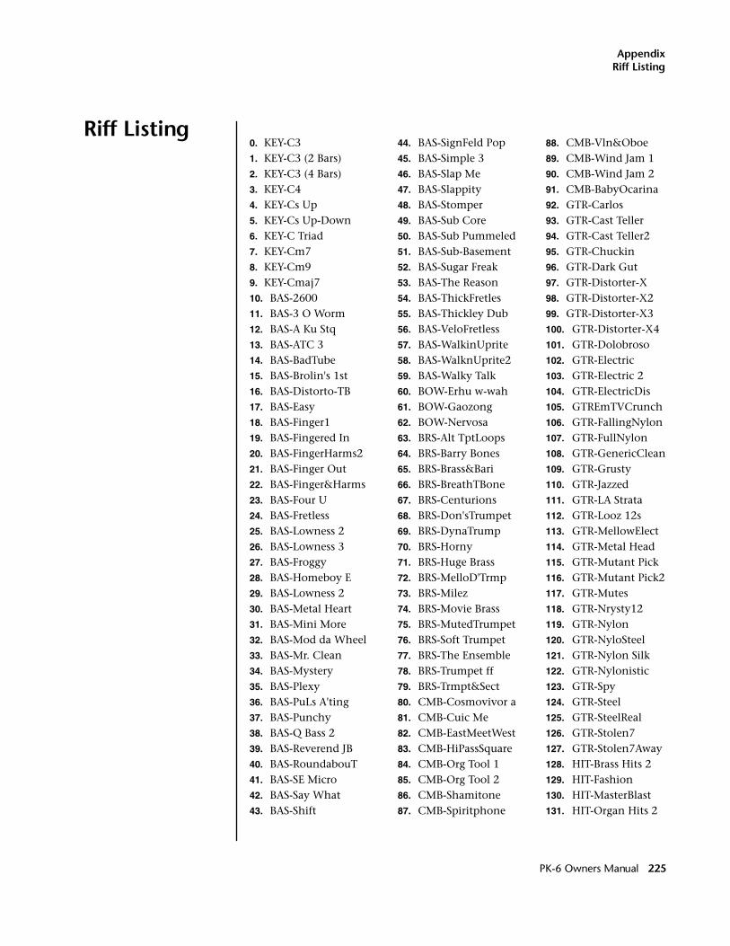
AppendixRiff Listing
Riff Listing0. KEY-C31. KEY-C3 (2 Bars)2. KEY-C3 (4 Bars)3. KEY-C44. KEY-Cs Up5. KEY-Cs Up-Down6. KEY-C Triad7. KEY-Cm78. KEY-Cm99. KEY-Cmaj710. BAS-260011. BAS-3 O Worm12. BAS-A Ku Stq13. BAS-ATC 314. BAS-BadTube15. BAS-Brolin's 1st16. BAS-Distorto-TB17. BAS-Easy18. BAS-Finger119. BAS-Fingered In20. BAS-FingerHarms221. BAS-Finger Out22. BAS-Finger&Harms23. BAS-Four U24. BAS-Fretless25. BAS-Lowness 226. BAS-Lowness 327. BAS-Froggy28. BAS-Homeboy E29. BAS-Lowness 230. BAS-Metal Heart31. BAS-Mini More32. BAS-Mod da Wheel33. BAS-Mr. Clean34. BAS-Mystery35. BAS-Plexy36. BAS-PuLs A'ting37. BAS-Punchy38. BAS-Q Bass 239. BAS-Reverend JB40. BAS-RoundabouT41. BAS-SE Micro42. BAS-Say What43. BAS-Shift
44. BAS-SignFeld Pop45. BAS-Simple 346. BAS-Slap Me47. BAS-Slappity48. BAS-Stomper49. BAS-Sub Core50. BAS-Sub Pummeled51. BAS-Sub-Basement52. BAS-Sugar Freak53. BAS-The Reason54. BAS-ThickFretles55. BAS-Thickley Dub56. BAS-VeloFretless57. BAS-WalkinUprite58. BAS-WalknUprite259. BAS-Walky Talk60. BOW-Erhu w-wah61. BOW-Gaozong62. BOW-Nervosa63. BRS-Alt TptLoops64. BRS-Barry Bones65. BRS-Brass&Bari66. BRS-BreathTBone67. BRS-Centurions68. BRS-Don'sTrumpet69. BRS-DynaTrump70. BRS-Horny71. BRS-Huge Brass72. BRS-MelloD'Trmp73. BRS-Milez74. BRS-Movie Brass75. BRS-MutedTrumpet76. BRS-Soft Trumpet77. BRS-The Ensemble78. BRS-Trumpet ff79. BRS-Trmpt&Sect80. CMB-Cosmovivor a81. CMB-Cuic Me82. CMB-EastMeetWest83. CMB-HiPassSquare84. CMB-Org Tool 185. CMB-Org Tool 286. CMB-Shamitone87. CMB-Spiritphone
88. CMB-Vln&Oboe89. CMB-Wind Jam 190. CMB-Wind Jam 291. CMB-BabyOcarina92. GTR-Carlos93. GTR-Cast Teller94. GTR-Cast Teller295. GTR-Chuckin96. GTR-Dark Gut97. GTR-Distorter-X98. GTR-Distorter-X299. GTR-Distorter-X3100. GTR-Distorter-X4101. GTR-Dolobroso102. GTR-Electric103. GTR-Electric 2104. GTR-ElectricDis105. GTREmTVCrunch106. GTR-FallingNylon107. GTR-FullNylon108. GTR-GenericClean109. GTR-Grusty110. GTR-Jazzed111. GTR-LA Strata112. GTR-Looz 12s113. GTR-MellowElect114. GTR-Metal Head115. GTR-Mutant Pick116. GTR-Mutant Pick2117. GTR-Mutes118. GTR-Nrysty12119. GTR-Nylon120. GTR-NyloSteel121. GTR-Nylon Silk122. GTR-Nylonistic123. GTR-Spy124. GTR-Steel125. GTR-SteelReal126. GTR-Stolen7127. GTR-Stolen7Away128. HIT-Brass Hits 2129. HIT-Fashion130. HIT-MasterBlast131. HIT-Organ Hits 2
PK-6 Owners Manual 225
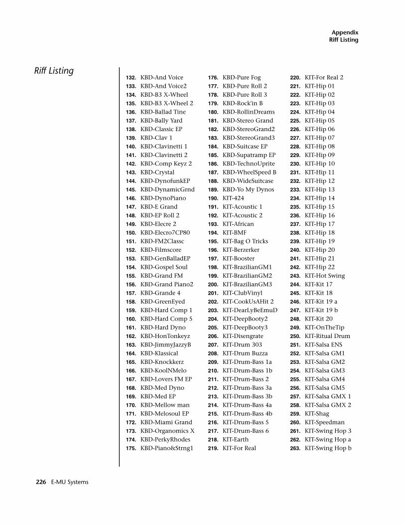
AppendixRiff Listing
Riff Listing132. KBD-And Voice133. KBD-And Voice2134. KBD-B3 X-Wheel135. KBD-B3 X-Wheel 2136. KBD-Ballad Tine137. KBD-Bally Yard138. KBD-Classic EP139. KBD-Clav 1140. KBD-Clavinetti 1141. KBD-Clavinetti 2142. KBD-Comp Keyz 2143. KBD-Crystal144. KBD-DynofunkEP145. KBD-DynamicGrnd146. KBD-DynoPiano147. KBD-E Grand148. KBD-EP Roll 2149. KBD-Elecre 2150. KBD-Elecro7CP80151. KBD-FM2Classc152. KBD-Filmscore153. KBD-GenBalladEP154. KBD-Gospel Soul155. KBD-Grand FM156. KBD-Grand Piano2157. KBD-Grande 4158. KBD-GreenEyed159. KBD-Hard Comp 1160. KBD-Hard Comp 5161. KBD-Hard Dyno162. KBD-HonTonkeyz163. KBD-JimmyJazzyB164. KBD-Klassical165. KBD-Knockkerz166. KBD-KoolNMelo167. KBD-Lovers FM EP168. KBD-Med Dyno169. KBD-Med EP170. KBD-Mellow man171. KBD-Melosoul EP172. KBD-Miami Grand173. KBD-Organomics X174. KBD-PerkyRhodes175. KBD-Piano&Strng1
176. KBD-Pure Fog177. KBD-Pure Roll 2178. KBD-Pure Roll 3179. KBD-Rock'in B180. KBD-RollinDreams181. KBD-Stereo Grand182. KBD-StereoGrand2183. KBD-StereoGrand3184. KBD-Suitcase EP185. KBD-Supatramp EP186. KBD-TechnoUprite187. KBD-WheelSpeed B188. KBD-WideSuitcase189. KBD-Yo My Dynos190. KIT-424191. KIT-Acoustic 1192. KIT-Acoustic 2193. KIT-African194. KIT-BMF195. KIT-Bag O Tricks196. KIT-Berzerker197. KIT-Booster198. KIT-BrazilianGM1199. KIT-BrazilianGM2200. KIT-BrazilianGM3201. KIT-ClubVinyl202. KIT-CookUsAHit 2203. KIT-DearLyBeEmuD204. KIT-DeepBooty2205. KIT-DeepBooty3206. KIT-Disengrate207. KIT-Drum 303208. KIT-Drum Buzza209. KIT-Drum-Bass 1a210. KIT-Drum-Bass 1b211. KIT-Drum-Bass 2212. KIT-Drum-Bass 3a213. KIT-Drum-Bass 3b214. KIT-Drum-Bass 4a215. KIT-Drum-Bass 4b216. KIT-Drum-Bass 5217. KIT-Drum-Bass 6218. KIT-Earth219. KIT-For Real
220. KIT-For Real 2221. KIT-Hip 01222. KIT-Hip 02223. KIT-Hip 03224. KIT-Hip 04225. KIT-Hip 05226. KIT-Hip 06227. KIT-Hip 07228. KIT-Hip 08229. KIT-Hip 09230. KIT-Hip 10231. KIT-Hip 11232. KIT-Hip 12233. KIT-Hip 13234. KIT-Hip 14235. KIT-Hip 15236. KIT-Hip 16237. KIT-Hip 17238. KIT-Hip 18239. KIT-Hip 19240. KIT-Hip 20241. KIT-Hip 21242. KIT-Hip 22243. KIT-Hot Swing244. KIT-Kit 17245. KIT-Kit 18246. KIT-Kit 19 a247. KIT-Kit 19 b248. KIT-Kit 20249. KIT-OnTheTip250. KIT-Ritual Drum251. KIT-Salsa ENS252. KIT-Salsa GM1253. KIT-Salsa GM2254. KIT-Salsa GM3255. KIT-Salsa GM4256. KIT-Salsa GM5257. KIT-Salsa GMX 1258. KIT-Salsa GMX 2259. KIT-Shag260. KIT-Speedman261. KIT-Swing Hop 3262. KIT-Swing Hop a263. KIT-Swing Hop b
226 E-MU Systems
AppendixRiff Listing
Riff Listing264. KIT-Tribal House265. KIT-World GM266. LED-Apple Eater267. LED-Blue Danube268. LED-Ethereosity269. LED-Freakus270. LED-inBottles271. LED-Post 90's DM272. LED-Q Snapper273. LED-Quacker274. LED-Sci-Fi B275. LED-Shiner276. LED-Soft Slip277. LED-Weezy Lead278. LED-Worm279. LED-Worm 2280. LED-Worm Up281. LED-Wormwood282. LED-Zimppler283. ORC-Combo284. ORC-Orchestra285. ORG-Blues286. ORG-Classical 1287. ORG-Classical 2288. ORG-Funk289. ORG-Fusion290. ORG-Gospel 1291. ORG-Gospel 2292. ORG-Gospel 3293. ORG-Jazz 1294. ORG-Jazz 2295. ORG-Latin 1296. ORG-Latin 2297. ORG-Tech 1298. ORG-Tech 2299. ORG-Variation 1300. ORG-Variation 2301. ORG-Variation 3302. ORG-Variation 4303. ORG-Variation 5304. ORG-Ballad305. PAD-Airborn306. PAD-Exotic 1307. PAD-Exotic 2
308. PAD-Exo Pad 2309. PAD-Exotic 3310. PAD-Exotic 4311. PAD-Exotic 5312. PAD-Exo Pad 1313. PAD-Ganic314. PAD-Highway315. PAD-Infants316. PAD-Infants2317. PAD-MetalBeats318. PAD-My Hero319. PAD-Pad Life320. PAD-Paddy321. PAD-Phat322. PAD-Sophia323. PLK-Celtic Harp324. PLK-SegDomraMut1325. PLK-Dulcolin326. PRC-Acidphone327. PRC-Balifon Ntrl328. PRC-BasBuBaliMar329. PRC-Blokba a330. PRC-Brazil Drums331. PRC-Celtic Perc332. PRC-Claves333. PRC-Congas334. PRC-Congas 2335. PRC-DmbkMbongo336. PRC-Cymbals337. PRC-HarpFantasy338. PRC-Hats 1339. PRC-Kalimba 2340. PRC-Limbafon341. PRC-Log On342. PRC-Marimba343. PRC-Metalofon344. PRC-Multipizz345. PRC-Pandebal346. PRC-Plexitone347. PRC-Progress a348. PRC-Shakers349. PRC-Snare 1350. PRC-Snare 2351. PRC-Steel Drum
352. PRC-Sweet Mar353. PRC-TV Spy Vibes354. PRC-Velo Vibes355. PRC-Velo Vibes 2356. PRC-Xylophone357. SFX-MetalScience358. SFX-Oh No Its359. SFX-P57K-009360. STR-AbbeyStrngs361. STR-AbbeyStrngs2362. STR-Allin a Pizz363. STR-AllinaPizz 2364. STR-AllinaPizz 3365. STR-ArcotremPizz366. STR-Dyna-heim367. STR-ExtremeStrng368. STR-Fiddle369. STR-Filmscore370. STR-HindooKurdoo371. STR-Japanman372. STR-Kult E Vatn373. STR-Orchestra 1374. STR-Orchestra 2375. STR-Pizzicati376. STR-SitarTalk377. STR-Solo Quartet378. STR-StrSection379. STR-Strg + Choir380. STR-Swoon381. STR-Texture382. STR-TronStrings383. STR-Velo Marcato384. STR-Victrola385. SYN-Bender386. SYN-Brazz387. SYN-Ensemblist388. SYN-Euro Wave389. SYN-Festival390. SYN-Hydraine391. SYN-ProfitMargin392. SYN-Silk OBXsaws393. SYN-Sync Trance394. SYN-Syntax On2395. SYN-Synthall AT
PK-6 Owners Manual 227
AppendixRiff Listing
Riff Listing396. SYN-ThinTecPulse397. SYN-Z&C Leeder398. VOX-Ahhs399. VOX-Frozen Time400. VOX-Lo-Fi Ether401. VOX-MauzeWowz402. VOX-Mist403. VOX-NewAge Oohs404. VOX-Odd Boys405. VOX-Pop Oohs406. VOX-Slo Lunarvox407. VOX-Spiritworld408. VOX-SynthSing409. VOX-Voxicord410. WAV-Lowtronics411. WAV-M12412. WAV-Metal 2413. WAV-vs37414. WND-A-Sax415. WND-Alto Saxo416. WND-Amazone417. WND-Bottle Blow418. WND-Breather419. WND-Chamber Orc420. WND-Clarinet421. WND-Clarinet 2422. WND-Eurasion423. WND-Ethnic Reed424. WND-Fieldberries425. WND-Flute426. WND-FluteScape427. WND-Harmonica428. WND-Nuages429. WND-Oboe430. WND-Ocarina a431. WND-Ocarina b432. WND-Pan Flute433. WND-Pastoral434. WND-Real Flute435. WND-Real Flute 2436. WND-Shenaidelic437. WND-Synth Flute438. WND-T-Sax439. WND-Virtuaccord440. WND-Wind Fingers
441. BTS-BigPimpin442. BTS-BiteZapper443. BTS-Bleak444. BTS-ChunkyButt445. BTS-CuzIWasStond446. BTS-Detourant447. BTS-Electro448. BTS-FilterPhaser449. BTS-Foggy450. BTS-FreakShifter451. BTS-InnaCity452. BTS-JungleClub453. BTS-Lowness454. BTS-MAD Donna455. BTS-Maestro456. BTS-Magnetic457. BTS-Moderno458. BTS-NuMetal459. BTS-Outside460. BTS-PhatterStill461. BTS-RadRacer462. BTS-RascllyRappr463. BTS-Ripped464. BTS-Rubbish465. BTS-Smasher466. BTS-Stringy467. BTS-WhatNow468. BTS-AllSteeley469. BTS-BassPatrol470. BTS-CrazyGtrs471. BTS-FaithHealer472. BTS-Groover473. BTS-Jam Man474. BTS-OldCombo475. BTS-PercJam476. BTS-StatikOne477. BTS-StreetBeat478. BTS-AmbientMood479. BTS-B There480. BTS-ClavFunk481. BTS-EP 1482. BTS-FM JazzSplit483. BTS-Gtr&Choir484. BTS-LoungingNOT485. BTS-Piano 1
486. BTS-Piano 2487. BTS-Piano 3488. BTS-Play It Cool489. BTS-Quick Beatz490. BTS-RealWurly491. BTS-Rhodes 1492. BTS-Rhodes 2493. BTS-Sentimental494. BTS-Vibes 1495. BTS-Vibes 2496. BTS-Pizz497. BTS-Solo&Sectn498. BTS-Laid&Back499. BTS-Clav On500. BTS-Grande501. BTS-GtrChoir502. BTS-PercB3503. BTS-PnoLyr504. BTS-PnoStrng505. BTS-RhodzR&B506. BTS-RhodzJzz507. BTS-SoloSctn508. BTS-Vibes 3509. BTS-JB Clav510. BTS-Butter511. BTS-PnoSalsa512. BTS-Pnosongo513. BTS-Orc514. BTS-NooagePizz515. BTS-EP 2516. BTS-Blues517. BTS-ChaCha518. BTS-Fireball519. BTS-Gospel520. BTS-Island521. BTS-latenite522. BTS-Minblues523. BTS-Presto524. BTS-Samba525. BTS-Sheek526. BTS-Slunk527. BTS-Stringy 2528. BTS-Tomrock529. BTS-SheekLead
228 E-MU Systems
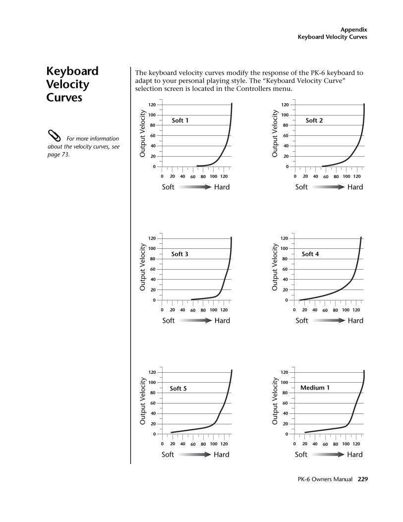
AppendixKeyboard Velocity Curves
Keyboard Velocity Curves
The keyboard velocity curves modify the response of the PK-6 keyboard to adapt to your personal playing style. The “Keyboard Velocity Curve” selection screen is located in the Controllers menu.
For more information about the velocity curves, see page 73.
Soft 1
0
20
40
60
80
100
120
0 20 40 60 80 100 120
Out
put
Vel
ocity
Soft Hard
Soft 2
0
20
40
60
80
100
120
0 20 40 60 80 100 120
Out
put
Vel
ocity
Soft Hard
Soft 3
0
20
40
60
80
100
120
0 20 40 60 80 100 120
Out
put
Vel
ocity
Soft Hard
0
20
40
60
80
100
120
0 20 40 60 80 100 120
Out
put
Vel
ocity
Soft 4
Soft Hard
0
20
40
60
80
100
120
0 20 40 60 80 100 120
Out
put
Vel
ocity
Soft 5
Soft Hard
0
20
40
60
80
100
120
0 20 40 60 80 100 120
Out
put
Vel
ocity
Medium 1
Soft Hard
PK-6 Owners Manual 229
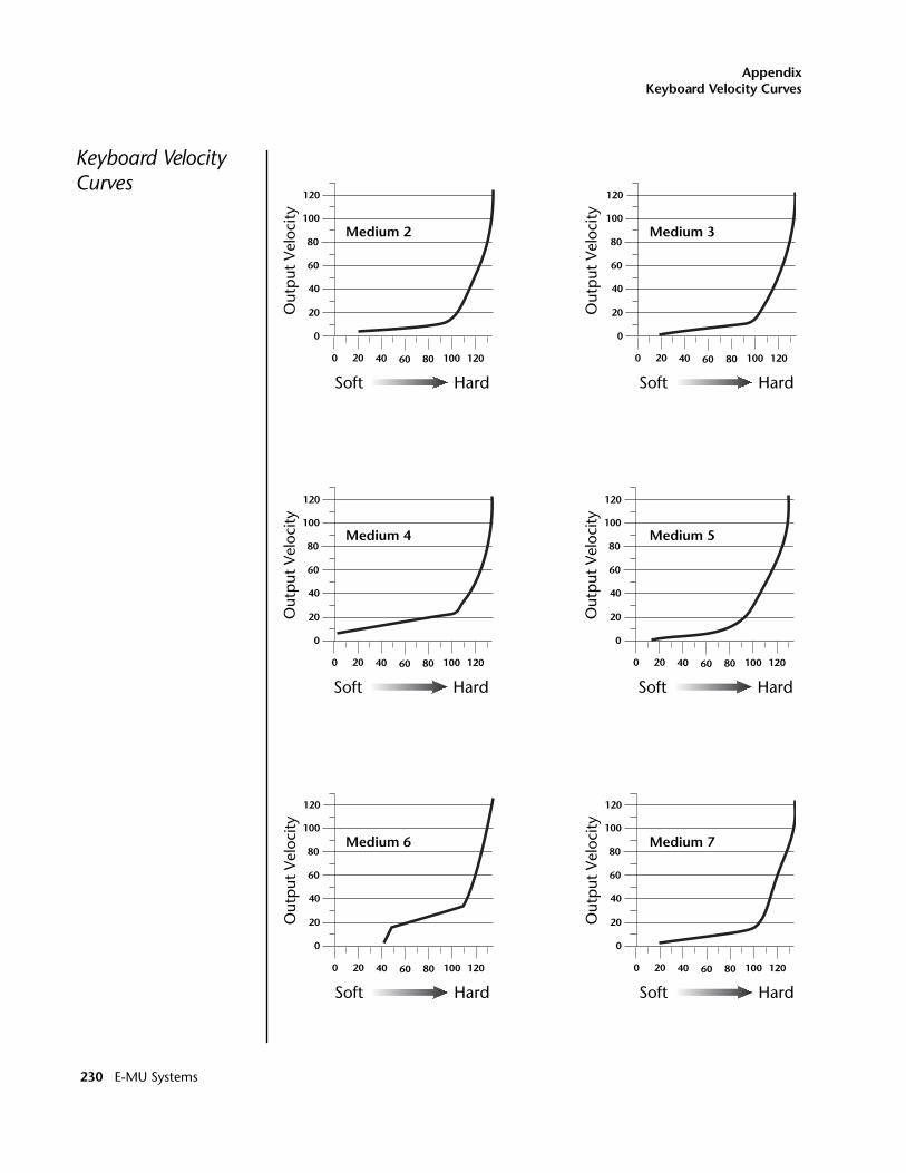
AppendixKeyboard Velocity Curves
Keyboard Velocity Curves
0
20
40
60
80
100
120
0 20 40 60 80 100 120
Out
put
Vel
ocity
Medium 2
Soft Hard
0
20
40
60
80
100
120
0 20 40 60 80 100 120
Out
put
Vel
ocity
Medium 3
Soft Hard
0
20
40
60
80
100
120
0 20 40 60 80 100 120
Out
put
Vel
ocity
Medium 4
Soft Hard
0
20
40
60
80
100
120
0 20 40 60 80 100 120
Out
put
Vel
ocity
Medium 5
Soft Hard
0
20
40
60
80
100
120
0 20 40 60 80 100 120
Out
put
Vel
ocity
Medium 6
Soft Hard
0
20
40
60
80
100
120
0 20 40 60 80 100 120
Out
put
Vel
ocity
Medium 7
Soft Hard
230 E-MU Systems
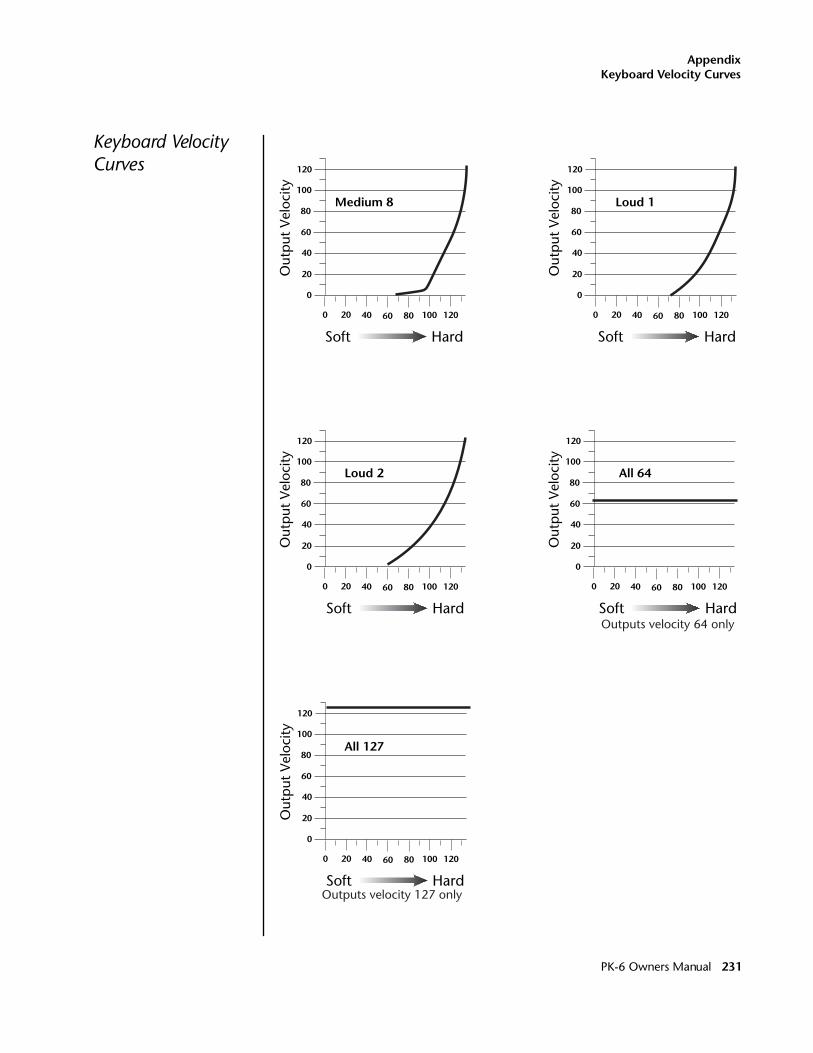
AppendixKeyboard Velocity Curves
Keyboard Velocity Curves
0
20
40
60
80
100
120
0 20 40 60 80 100 120
Out
put
Vel
ocity
Medium 8
Soft Hard
0
20
40
60
80
100
120
0 20 40 60 80 100 120
Out
put
Vel
ocity
Loud 1
Soft Hard
0
20
40
60
80
100
120
0 20 40 60 80 100 120
Out
put
Vel
ocity
Loud 2
Soft Hard
0
20
40
60
80
100
120
0 20 40 60 80 100 120
Out
put
Vel
ocity
All 64
Outputs velocity 64 onlySoft Hard
0
20
40
60
80
100
120
0 20 40 60 80 100 120
Out
put
Vel
ocity
All 127
Outputs velocity 127 onlySoft Hard
PK-6 Owners Manual 231
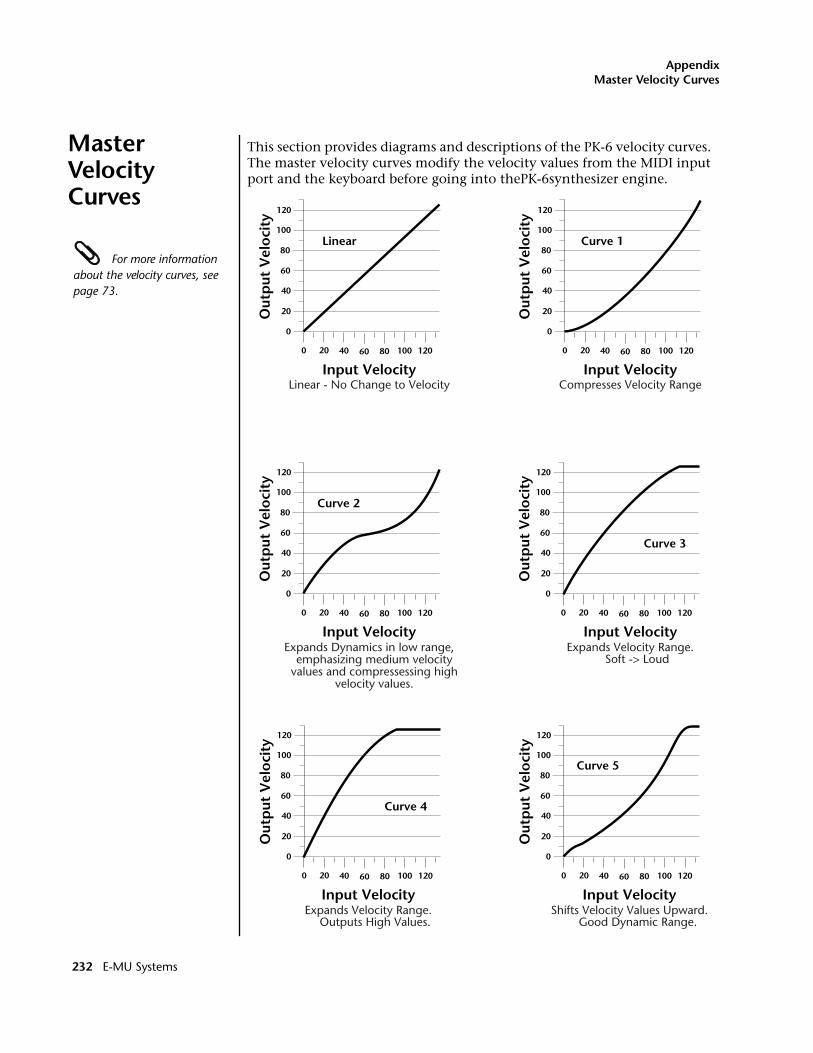
AppendixMaster Velocity Curves
Master Velocity Curves
This section provides diagrams and descriptions of the PK-6 velocity curves. The master velocity curves modify the velocity values from the MIDI input port and the keyboard before going into thePK-6synthesizer engine.
For more information about the velocity curves, see page 73.
Curve 1
0
20
40
60
80
100
120
0 20 40 60 80 100 120
Out
put
Vel
oci
ty
Curve 2
0
20
40
60
80
100
120
0 20 40 60 80 100 120
Out
put
Vel
oci
ty
0
20
40
60
80
100
120
0 20 40 60 80 100 120
Out
put
Vel
oci
tyCurve 3
0
20
40
60
80
100
120
0 20 40 60 80 100 120
Out
put
Vel
oci
ty
Curve 4
Linear
0
20
40
60
80
100
120
0 20 40 60 80 100 120
Out
put
Vel
oci
ty
0
20
40
60
80
100
120
0 20 40 60 80 100 120
Out
put
Vel
oci
ty
Curve 5
Input VelocityLinear - No Change to Velocity
Input VelocityCompresses Velocity Range
Input Velocity Input Velocity
Input Velocity Input Velocity
Expands Dynamics in low range, emphasizing medium velocity
values and compressessing high velocity values.
Expands Velocity Range. Soft -> Loud
Expands Velocity Range. Outputs High Values.
Shifts Velocity Values Upward. Good Dynamic Range.
232 E-MU Systems
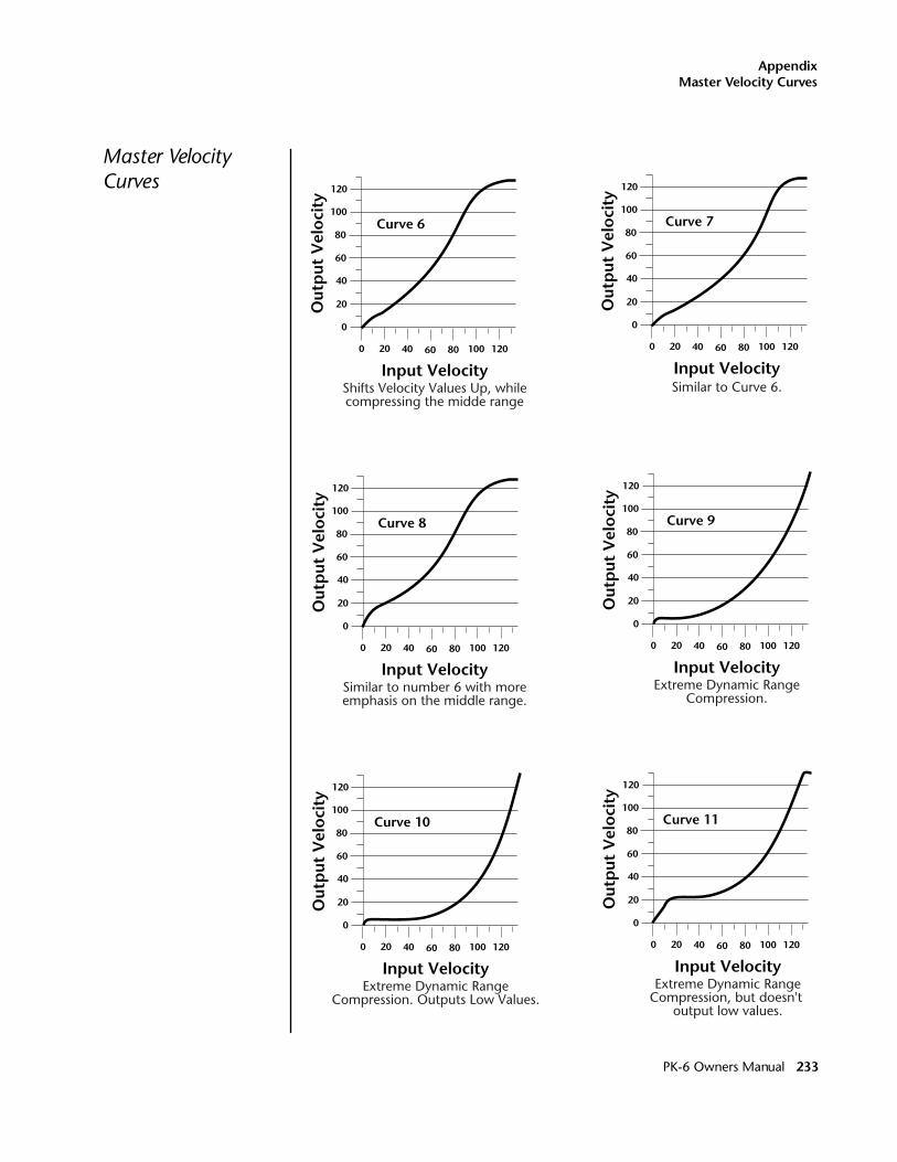
AppendixMaster Velocity Curves
Master Velocity Curves
0
20
40
60
80
100
120
0 20 40 60 80 100 120
Out
put
Vel
oci
ty
Curve 6
0
20
40
60
80
100
120
0 20 40 60 80 100 120
Out
put
Vel
oci
ty
Curve 7
0
20
40
60
80
100
120
0 20 40 60 80 100 120
Out
put
Vel
oci
ty
Curve 8
0
20
40
60
80
100
120
0 20 40 60 80 100 120
Out
put
Vel
oci
ty
Curve 10
0
20
40
60
80
100
120
0 20 40 60 80 100 120
Out
put
Vel
oci
ty
Curve 11
Input Velocity Input Velocity
Input Velocity
0
20
40
60
80
100
120
0 20 40 60 80 100 120
Out
put
Vel
oci
ty
Curve 9
Input Velocity
Input Velocity Input Velocity
Shifts Velocity Values Up, whilecompressing the midde range
Similar to Curve 6.
Similar to number 6 with moreemphasis on the middle range.
Extreme Dynamic RangeCompression.
Extreme Dynamic RangeCompression. Outputs Low Values.
Extreme Dynamic RangeCompression, but doesn't
output low values.
PK-6 Owners Manual 233
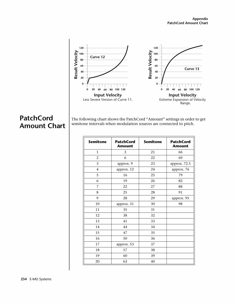
AppendixPatchCord Amount Chart
PatchCord Amount Chart
The following chart shows the PatchCord “Amount” settings in order to get semitone intervals when modulation sources are connected to pitch.
0
20
40
60
80
100
120
0 20 40 60 80 100 120
Res
ult
Vel
oci
ty
Curve 12
0
20
40
60
80
100
120
0 20 40 60 80 100 120
Res
ult
Vel
oci
ty
Curve 13
Input Velocity Input VelocityLess Severe Version of Curve 11. Extreme Expansion of Velocity
Range.
Semitone PatchCord Amount
Semitone PatchCord Amount
1 3 21 66
2 6 22 69
3 approx. 9 23 approx. 72.5
4 approx. 12 24 approx. 76
5 16 25 79
6 19 26 82
7 22 27 88
8 25 28 91
9 28 29 approx. 95
10 approx. 31 30 98
11 35 31
12 38 32
13 41 33
14 44 34
15 47 35
16 50 36
17 approx. 53 37
18 57 38
19 60 39
20 63 40
234 E-MU Systems
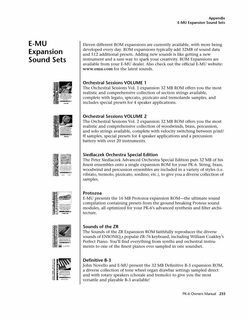
AppendixE-MU Expansion Sound Sets
E-MU Expansion Sound Sets
Eleven different ROM expansions are currently available, with more being developed every day. ROM expansions typically add 32MB of sound data and 512 additional presets. Adding new sounds is like getting a new instrument and a sure way to spark your creativity. ROM Expansions are available from your E-MU dealer. Also check out the official E-MU website: www.emu.com for the latest sounds.
Orchestral Sessions VOLUME 1The Orchestral Sessions Vol. 1 expansion 32 MB ROM offers you the most realistic and comprehensive collection of section strings available, complete with legato, spiccato, pizzicato and tremolande samples, and includes special presets for 4 speaker applications.
Orchestral Sessions VOLUME 2 The Orchestral Sessions Vol. 2 expansion 32 MB ROM offers you the most realistic and comprehensive collection of woodwinds, brass, percussion, and solo strings available, complete with velocity switching between p/mf/ff samples, special presets for 4 speaker applications and a percussion battery with over 20 instruments.
Siedlaczek Orchestra Special Edition The Peter Siedlaczek Advanced Orchestra Special Edition puts 32 MB of his finest ensembles onto a single expansion ROM for your PK-6. String, brass, woodwind and percussion ensembles are included in a variety of styles (i.e. vibrato, tremolo, pizzicato, sordino, etc.), to give you a diverse collection of samples.
ProtozoaE-MU presents the 16 MB Protozoa expansion ROM—the ultimate sound compilation containing presets from the ground breaking Proteus sound modules, all optimized for your PK-6’s advanced synthesis and filter archi-tecture.
Sounds of the ZR The Sounds of the ZR Expansion ROM faithfully reproduces the diverse sounds of ENSONIQ‚s popular ZR-76 keyboard, including William Coakley’s Perfect Piano. You’ll find everything from synths and orchestral instru-ments to one of the finest pianos ever sampled in one soundset.
Definitive B-3John Novello and E-MU present the 32 MB Definitive B-3 expansion ROM, a diverse collection of tone wheel organ drawbar settings sampled direct and with rotary speakers (chorale and tremolo) to give you the most versatile and playable B-3 available!
PK-6 Owners Manual 235
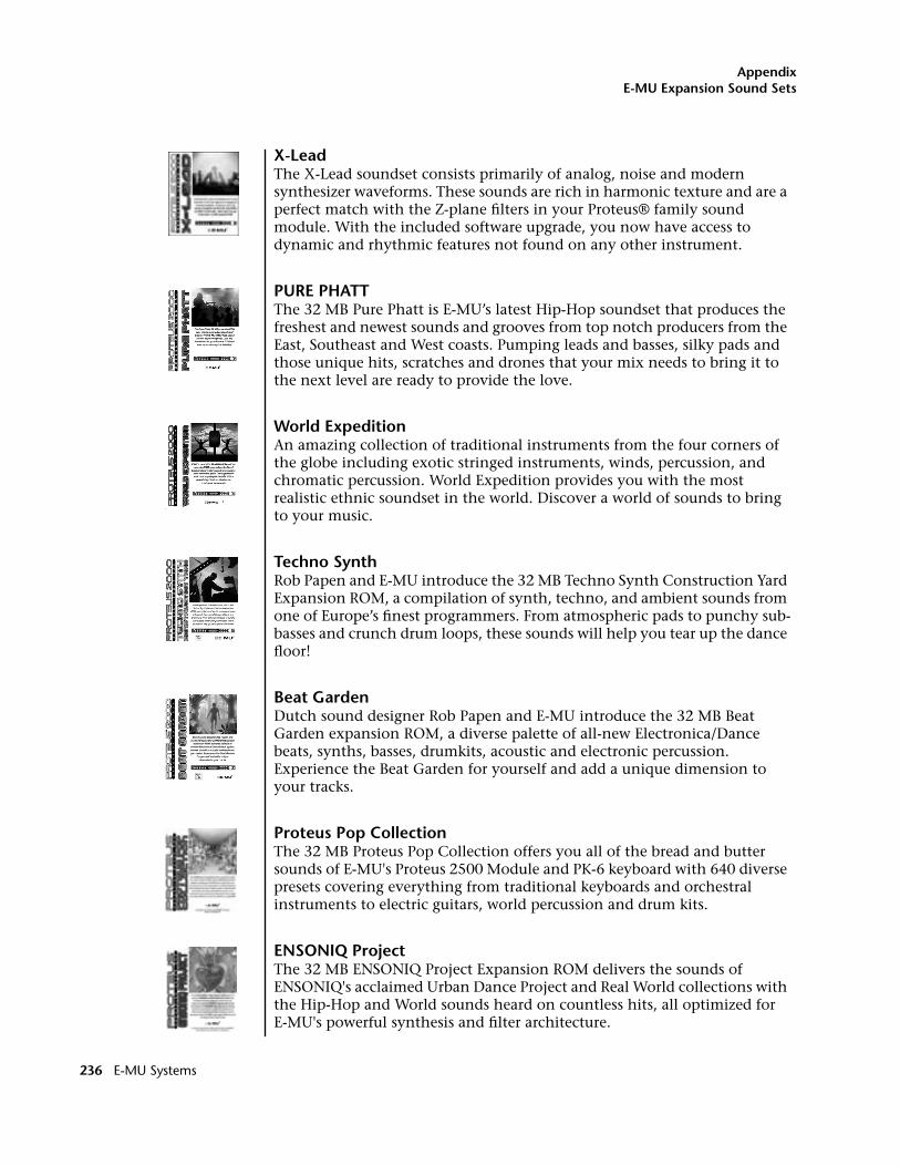
AppendixE-MU Expansion Sound Sets
X-LeadThe X-Lead soundset consists primarily of analog, noise and modern synthesizer waveforms. These sounds are rich in harmonic texture and are a perfect match with the Z-plane filters in your Proteus® family sound module. With the included software upgrade, you now have access to dynamic and rhythmic features not found on any other instrument.
PURE PHATTThe 32 MB Pure Phatt is E-MU’s latest Hip-Hop soundset that produces the freshest and newest sounds and grooves from top notch producers from the East, Southeast and West coasts. Pumping leads and basses, silky pads and those unique hits, scratches and drones that your mix needs to bring it to the next level are ready to provide the love.
World ExpeditionAn amazing collection of traditional instruments from the four corners of the globe including exotic stringed instruments, winds, percussion, and chromatic percussion. World Expedition provides you with the most realistic ethnic soundset in the world. Discover a world of sounds to bring to your music.
Techno SynthRob Papen and E-MU introduce the 32 MB Techno Synth Construction Yard Expansion ROM, a compilation of synth, techno, and ambient sounds from one of Europe’s finest programmers. From atmospheric pads to punchy sub-basses and crunch drum loops, these sounds will help you tear up the dance floor!
Beat GardenDutch sound designer Rob Papen and E-MU introduce the 32 MB Beat Garden expansion ROM, a diverse palette of all-new Electronica/Dance beats, synths, basses, drumkits, acoustic and electronic percussion. Experience the Beat Garden for yourself and add a unique dimension to your tracks.
Proteus Pop CollectionThe 32 MB Proteus Pop Collection offers you all of the bread and butter sounds of E-MU's Proteus 2500 Module and PK-6 keyboard with 640 diverse presets covering everything from traditional keyboards and orchestral instruments to electric guitars, world percussion and drum kits.
ENSONIQ ProjectThe 32 MB ENSONIQ Project Expansion ROM delivers the sounds of ENSONIQ's acclaimed Urban Dance Project and Real World collections with the Hip-Hop and World sounds heard on countless hits, all optimized for E-MU's powerful synthesis and filter architecture.
236 E-MU Systems
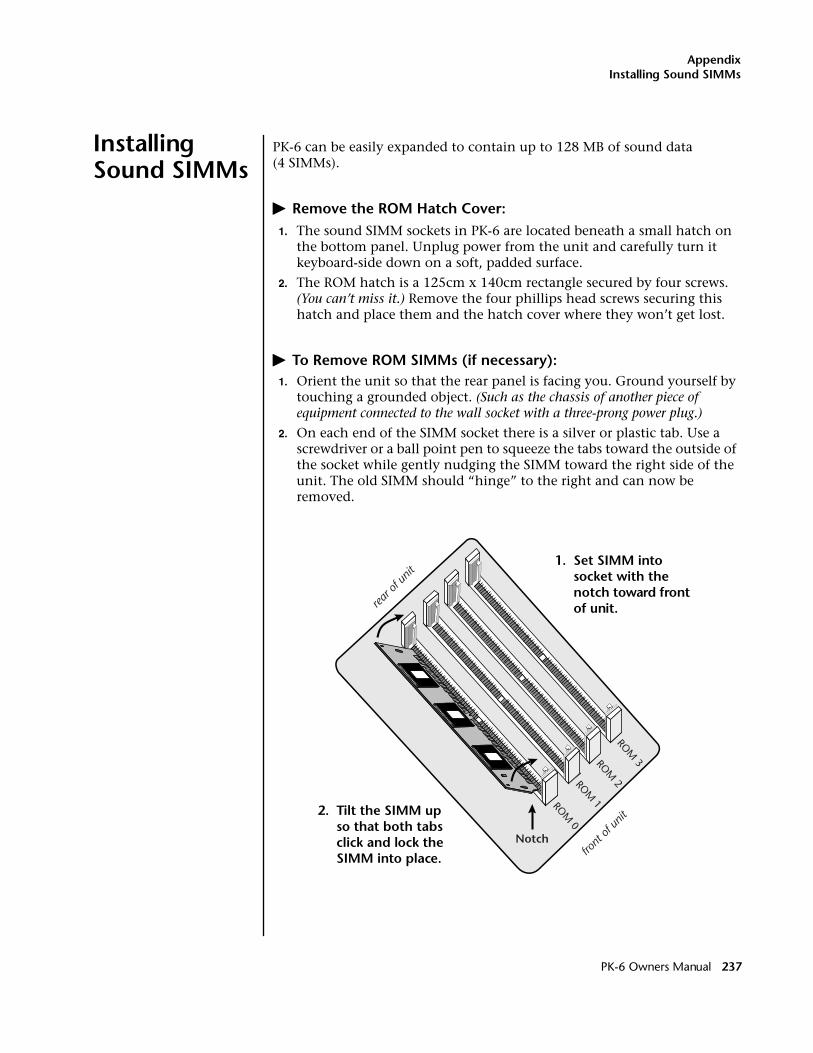
AppendixInstalling Sound SIMMs
Installing Sound SIMMs
PK-6 can be easily expanded to contain up to 128 MB of sound data (4 SIMMs).
� Remove the ROM Hatch Cover:1. The sound SIMM sockets in PK-6 are located beneath a small hatch on
the bottom panel. Unplug power from the unit and carefully turn it keyboard-side down on a soft, padded surface.
2. The ROM hatch is a 125cm x 140cm rectangle secured by four screws. (You can’t miss it.) Remove the four phillips head screws securing this hatch and place them and the hatch cover where they won’t get lost.
� To Remove ROM SIMMs (if necessary):1. Orient the unit so that the rear panel is facing you. Ground yourself by
touching a grounded object. (Such as the chassis of another piece of equipment connected to the wall socket with a three-prong power plug.)
2. On each end of the SIMM socket there is a silver or plastic tab. Use a screwdriver or a ball point pen to squeeze the tabs toward the outside of the socket while gently nudging the SIMM toward the right side of the unit. The old SIMM should “hinge” to the right and can now be removed.
ROM 3ROM
2ROM 1ROM
0
Notch
rear o
f unit
front
of un
it2. Tilt the SIMM up so that both tabs click and lock the SIMM into place.
1. Set SIMM into socket with the notch toward front of unit.
PK-6 Owners Manual 237
AppendixInstalling Sound SIMMs
� Install a New ROM SIMM1. Ground yourself by touching a grounded object, then remove the
memory SIMM modules from the static protected packaging.
2. Notice that one end of the SIMM connector is notched. This notch should be oriented towards the keyboard side of the unit. Install the SIMM closest to the LEFT side first. (When the rear of the unit is closest to you.)
3. Gently set the SIMM deep into the SIMM socket at a 45º angle with the notch toward the keyboard. Without forcing the insertion, let the board rest in the socket as deep as it will go. It should rest naturally in place at this 45° angle. See the following diagrams.
4. While applying a slight downward pressure on the top of the SIMM to keep it from popping out of the socket, tilt the SIMM board into a vertical position. You should hear an audible click. Make sure both sides of the silver tabs have latched.
� Reassemble the Unit5. Replace the hatch cover and the four screws. The screws are all
identical.
� Test ItThe installation is almost finished.
1. Turn the unit right-side up and plug in the power cord.
2. Turn on power.
3. Place the cursor under the ROM field of the Main screen and turn the data entry control to verify that the new sound ROM has been recog-nized.
4. Play the presets on the new ROM banks and verify that they sound OK.
Problems?1. Disconnect power immediately.
2. Open the unit, and try re-seating the ROM SIMMs. Take care that the RAM SIMMs are properly installed in the sockets. If you’re still having problems, return the unit to its original configuration and call EMU / ENSONIQ Customer Service at (831) 438-1921. Telephone support hours are 8:00-5:00 PST, Monday through Friday.
238 E-MU Systems
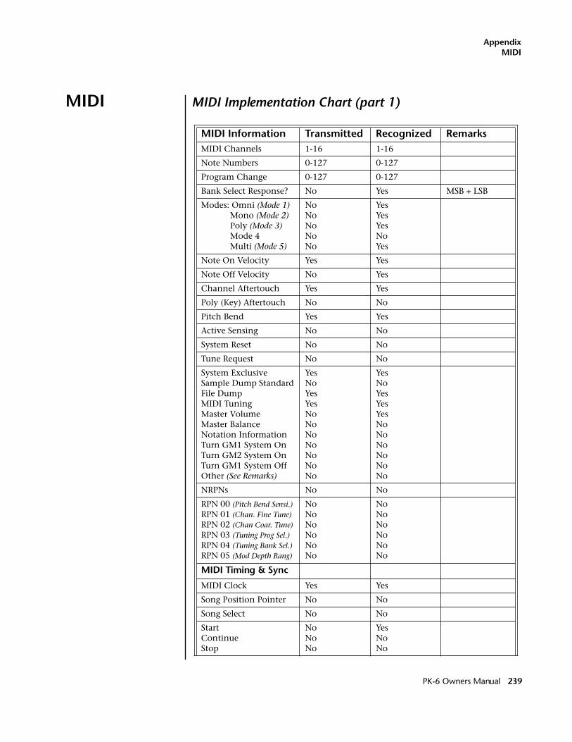
AppendixMIDI
MIDI MIDI Implementation Chart (part 1)
MIDI Information Transmitted Recognized RemarksMIDI Channels 1-16 1-16
Note Numbers 0-127 0-127
Program Change 0-127 0-127
Bank Select Response? No Yes MSB + LSB
Modes: Omni (Mode 1) Mono (Mode 2) Poly (Mode 3) Mode 4 Multi (Mode 5)
NoNoNoNoNo
YesYesYesNoYes
Note On Velocity Yes Yes
Note Off Velocity No Yes
Channel Aftertouch Yes Yes
Poly (Key) Aftertouch No No
Pitch Bend Yes Yes
Active Sensing No No
System Reset No No
Tune Request No No
System ExclusiveSample Dump StandardFile DumpMIDI TuningMaster VolumeMaster BalanceNotation InformationTurn GM1 System OnTurn GM2 System OnTurn GM1 System OffOther (See Remarks)
YesNoYesYesNoNoNoNoNoNoNo
YesNoYesYesYesNoNoNoNoNoNo
NRPNs No No
RPN 00 (Pitch Bend Sensi.)RPN 01 (Chan. Fine Tune)RPN 02 (Chan Coar. Tune)RPN 03 (Tuning Prog Sel.)RPN 04 (Tuning Bank Sel.)RPN 05 (Mod Depth Rang)
NoNoNoNoNoNo
NoNoNoNoNoNo
MIDI Timing & Sync
MIDI Clock Yes Yes
Song Position Pointer No No
Song Select No No
StartContinueStop
NoNoNo
YesNoNo
PK-6 Owners Manual 239
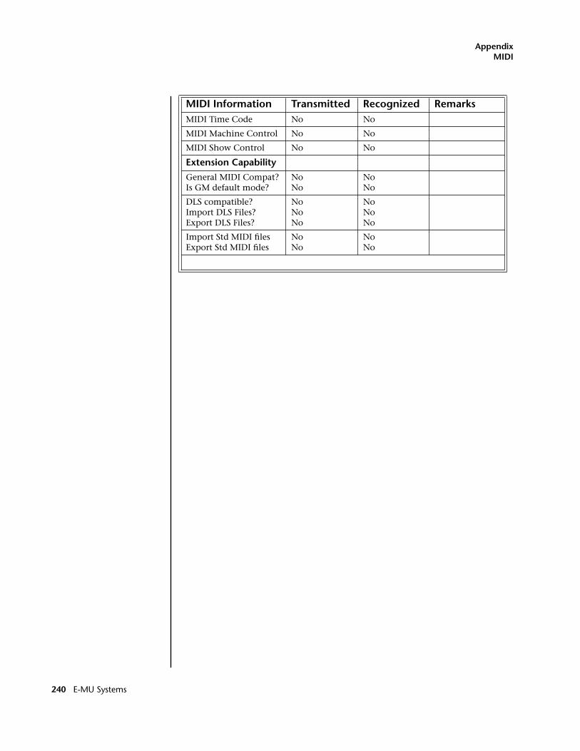
AppendixMIDI
MIDI Time Code No No
MIDI Machine Control No No
MIDI Show Control No No
Extension Capability
General MIDI Compat?Is GM default mode?
NoNo
NoNo
DLS compatible?Import DLS Files?Export DLS Files?
NoNoNo
NoNoNo
Import Std MIDI filesExport Std MIDI files
NoNo
NoNo
MIDI Information Transmitted Recognized Remarks
240 E-MU Systems
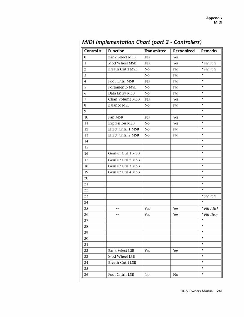
AppendixMIDI
MIDI Implementation Chart (part 2 - Controllers)Control # Function Transmitted Recognized Remarks
0 Bank Select MSB Yes Yes
1 Mod Wheel MSB Yes Yes * see note
2 Breath Cntrl MSB No No * see note
3 No No *
4 Foot Cntrl MSB Yes No *
5 Portamento MSB No No *
6 Data Entry MSB No No *
7 Chan Volume MSB Yes Yes *
8 Balance MSB No No *
9 *
10 Pan MSB Yes Yes *
11 Expression MSB No Yes *
12 Effect Cntrl 1 MSB No No *
13 Effect Cntrl 2 MSB No No *
14 *
15 *
16 GenPur Ctrl 1 MSB *
17 GenPur Ctrl 2 MSB *
18 GenPur Ctrl 3 MSB *
19 GenPur Ctrl 4 MSB *
20 *
21 *
22 *
23 * see note
24 *
25 ™ Yes Yes * Filt Attck
26 ™ Yes Yes * Filt Decy
27 *
28 *
29 *
30 *
31 *
32 Bank Select LSB Yes Yes *
33 Mod Wheel LSB *
34 Breath Cntrl LSB *
35 *
36 Foot Cntrlr LSB No No *
PK-6 Owners Manual 241
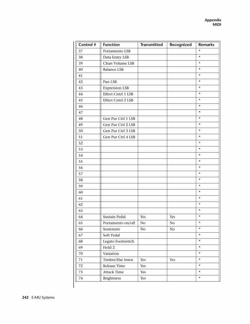
AppendixMIDI
37 Portamento LSB *
38 Data Entry LSB *
39 Chan Volume LSB *
40 Balance LSB *
41 *
42 Pan LSB *
43 Expression LSB *
44 Effect Cntrl 1 LSB *
45 Effect Cntrl 2 LSB *
46 *
47 *
48 Gen Pur Ctrl 1 LSB *
49 Gen Pur Ctrl 2 LSB *
50 Gen Pur Ctrl 3 LSB *
51 Gen Pur Ctrl 4 LSB *
52 *
53 *
54 *
55 *
56 *
57 *
58 *
59 *
60 *
61 *
62 *
63 *
64 Sustain Pedal Yes Yes *
65 Portamento on/off No No *
66 Sostenuto No No *
67 Soft Pedal *
68 Legato Footswitch *
69 Hold 2 *
70 Variation *
71 Timbre/Har Inten Yes Yes *
72 Release Time Yes *
73 Attack Time Yes *
74 Brightness Yes *
Control # Function Transmitted Recognized Remarks
242 E-MU Systems
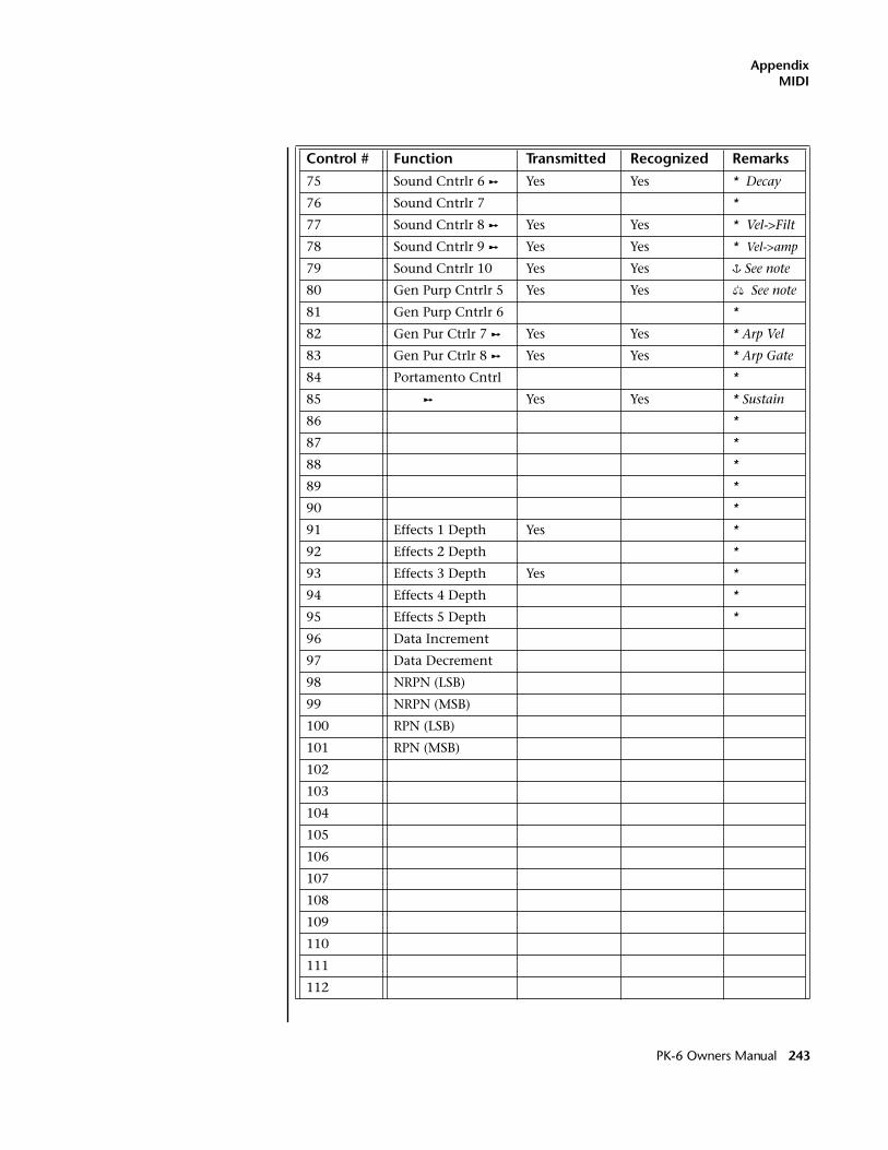
AppendixMIDI
75 Sound Cntrlr 6 ™ Yes Yes * Decay
76 Sound Cntrlr 7 *
77 Sound Cntrlr 8 ™ Yes Yes * Vel->Filt
78 Sound Cntrlr 9 ™ Yes Yes * Vel->amp
79 Sound Cntrlr 10 Yes Yes � See note
80 Gen Purp Cntrlr 5 Yes Yes � See note
81 Gen Purp Cntrlr 6 *
82 Gen Pur Ctrlr 7 ™ Yes Yes * Arp Vel
83 Gen Pur Ctrlr 8 ™ Yes Yes * Arp Gate
84 Portamento Cntrl *
85 ™ Yes Yes * Sustain
86 *
87 *
88 *
89 *
90 *
91 Effects 1 Depth Yes *
92 Effects 2 Depth *
93 Effects 3 Depth Yes *
94 Effects 4 Depth *
95 Effects 5 Depth *
96 Data Increment
97 Data Decrement
98 NRPN (LSB)
99 NRPN (MSB)
100 RPN (LSB)
101 RPN (MSB)
102
103
104
105
106
107
108
109
110
111
112
Control # Function Transmitted Recognized Remarks
PK-6 Owners Manual 243
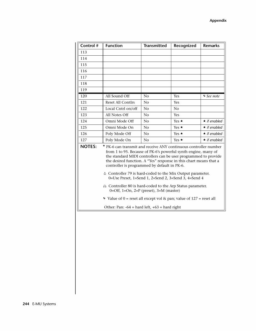
AppendixMIDI
113
114
115
116
117
118
119
120 All Sound Off No Yes � See note
121 Reset All Contlrs No Yes
122 Local Cntrl on/off No No
123 All Notes Off No Yes
124 Omni Mode Off No Yes � � if enabled
125 Omni Mode On No Yes � � if enabled
126 Poly Mode Off No Yes � � if enabled
127 Poly Mode On No Yes � � if enabled
NOTES: * PK-6 can transmit and receive ANY continuous controller number from 1 to 95. Because of PK-6’s powerful synth engine, many of the standard MIDI controllers can be user programmed to provide the desired function. A “Yes” response in this chart means that a controller is programmed by default in PK-6.
� Controller 79 is hard-coded to the Mix Output parameter. 0=Use Preset, 1=Send 1, 2=Send 2, 3=Send 3, 4=Send 4
� Controller 80 is hard-coded to the Arp Status parameter. 0=Off, 1=On, 2=P (preset), 3=M (master)
� Value of 0 = reset all except vol & pan; value of 127 = reset all
Other: Pan: -64 = hard left, +63 = hard right
Control # Function Transmitted Recognized Remarks
244 E-MU Systems
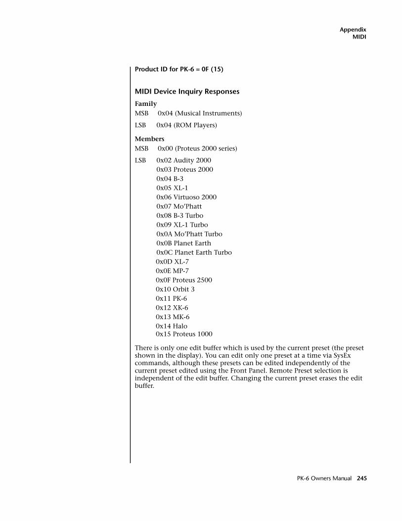
AppendixMIDI
Product ID for PK-6 = 0F (15)
MIDI Device Inquiry Responses
FamilyMSB 0x04 (Musical Instruments)
LSB 0x04 (ROM Players)
MembersMSB 0x00 (Proteus 2000 series)
LSB 0x02 Audity 20000x03 Proteus 20000x04 B-30x05 XL-10x06 Virtuoso 20000x07 Mo’Phatt0x08 B-3 Turbo0x09 XL-1 Turbo0x0A Mo’Phatt Turbo0x0B Planet Earth0x0C Planet Earth Turbo0x0D XL-70x0E MP-70x0F Proteus 25000x10 Orbit 30x11 PK-60x12 XK-60x13 MK-60x14 Halo0x15 Proteus 1000
There is only one edit buffer which is used by the current preset (the preset shown in the display). You can edit only one preset at a time via SysEx commands, although these presets can be edited independently of the current preset edited using the Front Panel. Remote Preset selection is independent of the edit buffer. Changing the current preset erases the edit buffer.
PK-6 Owners Manual 245
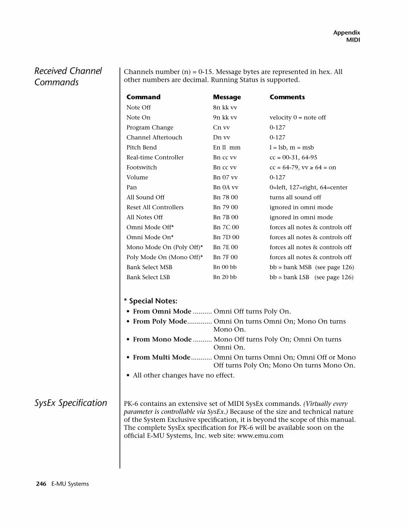
AppendixMIDI
Received Channel Commands
Channels number (n) = 0-15. Message bytes are represented in hex. All other numbers are decimal. Running Status is supported.
* Special Notes:• From Omni Mode .......... Omni Off turns Poly On.
• From Poly Mode............. Omni On turns Omni On; Mono On turns Mono On.
• From Mono Mode .......... Mono Off turns Poly On; Omni On turns Omni On.
• From Multi Mode ........... Omni On turns Omni On; Omni Off or Mono Off turns Poly On; Mono On turns Mono On.
• All other changes have no effect.
SysEx Specification PK-6 contains an extensive set of MIDI SysEx commands. (Virtually every parameter is controllable via SysEx.) Because of the size and technical nature of the System Exclusive specification, it is beyond the scope of this manual. The complete SysEx specification for PK-6 will be available soon on the official E-MU Systems, Inc. web site: www.emu.com
Command Message Comments
Note Off 8n kk vv
Note On 9n kk vv velocity 0 = note off
Program Change Cn vv 0-127
Channel Aftertouch Dn vv 0-127
Pitch Bend En ll mm l = lsb, m = msb
Real-time Controller Bn cc vv cc = 00-31, 64-95
Footswitch Bn cc vv cc = 64-79, vv ≥ 64 = on
Volume Bn 07 vv 0-127
Pan Bn 0A vv 0=left, 127=right, 64=center
All Sound Off Bn 78 00 turns all sound off
Reset All Controllers Bn 79 00 ignored in omni mode
All Notes Off Bn 7B 00 ignored in omni mode
Omni Mode Off* Bn 7C 00 forces all notes & controls off
Omni Mode On* Bn 7D 00 forces all notes & controls off
Mono Mode On (Poly Off)* Bn 7E 00 forces all notes & controls off
Poly Mode On (Mono Off)* Bn 7F 00 forces all notes & controls off
Bank Select MSB Bn 00 bb bb = bank MSB (see page 126)
Bank Select LSB Bn 20 bb bb = bank LSB (see page 126)
246 E-MU Systems
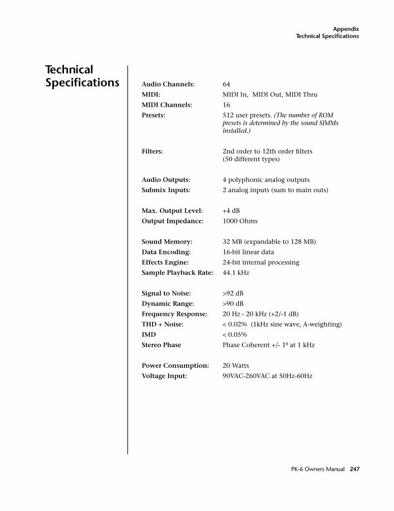
AppendixTechnical Specifications
Technical Specifications Audio Channels: 64
MIDI: MIDI In, MIDI Out, MIDI Thru
MIDI Channels: 16
Presets: 512 user presets. (The number of ROM presets is determined by the sound SIMMs installed.)
Filters: 2nd order to 12th order filters(50 different types)
Audio Outputs: 4 polyphonic analog outputs
Submix Inputs: 2 analog inputs (sum to main outs)
Max. Output Level: +4 dB
Output Impedance: 1000 Ohms
Sound Memory: 32 MB (expandable to 128 MB)
Data Encoding: 16-bit linear data
Effects Engine: 24-bit internal processing
Sample Playback Rate: 44.1 kHz
Signal to Noise: >92 dB
Dynamic Range: >90 dB
Frequency Response: 20 Hz - 20 kHz (+2/-1 dB)
THD + Noise: < 0.02% (1kHz sine wave, A-weighting)
IMD < 0.05%
Stereo Phase Phase Coherent +/- 1º at 1 kHz
Power Consumption: 20 Watts
Voltage Input: 90VAC-260VAC at 50Hz-60Hz
PK-6 Owners Manual 247
AppendixWarranty
Warranty Please read this warranty, as it gives you specific legal rights.
Limited Warranty This product is warranted, to the original consumer purchaser, to be free of all defects in workmanship and materials for a period of one (1) year (warranty period is two (2) years in the European Union, effective Jan-1-2002), from the date of such purchase from an authorized E-MU/ ENSONIQ dealer, provided that: (a) the Warranty Registration Card is filled out and returned to E-MU / ENSONIQ within 14 days of the purchase date; (b) the E-MU / ENSONIQ service center is provided a copy of the consumer purchaser’s sales receipt; and (c) E-MU / ENSONIQ has confirmed the validity of the subject unit's serial number.
Warranty Restrictions
Specifically, but without limitation, E-MU / ENSONIQ does not provide warranty service for:
• Damages due to improper or inadequate maintenance, accident, abuse, misuse, alteration, unauthorized repairs, tampering, or failure to follow normal operating procedures as outlined in the owner’s manual;
• Deterioration or damage of the cabinet;
• Damages occurring during any shipment of the unit;
• Any unit which has been modified by anyone other than E-MU / ENSONIQ.
• Any unit with an invalid or wholly or partially obliterated serial number.
NO OTHER EXPRESS OR IMPLIED WARRANTY IS MADE, AND E-MU / ENSONIQ SPECIFICALLY DISCLAIMS ANY IMPLIED WARRANTY OF MERCHANTABILITY, SATISFACTORY QUALITY, AND FITNESS FOR A PARTICULAR PURPOSE. E-MU / ENSONIQ’S LIABILITY UNDER WARRANTY IS LIMITED TO REPAIR OR REPLACEMENT OF THE UNIT, OR REFUND, AT EMU’S OPTION. IN NO EVENT WILL E-MU / ENSONIQ BE LIABLE FOR LOSS OF REVENUE OR SAVINGS, LOSS OF TIME, INTER-RUPTION OF USE, OR ANY OTHER CONSEQUENTIAL, INDIRECT, INCIDENTAL, SPECIAL OR EXEMPLARY DAMAGES.
The foregoing will apply notwithstanding the failure of essential purpose of any remedy provided herein. Some jurisdictions do not allow the exclusion of implied warranties or conditions, or limitations on how long an implied warranty or condition may last, so the above limitations may not apply. This warranty gives you specific legal rights. You may have other rights which vary from jurisdiction to jurisdiction.
248 E-MU Systems
AppendixWarranty
How To Obtain Warranty Service
All E-MU / ENSONIQ products are manufactured with the highest standards of quality. If you find that your unit does require service, it may be done by any authorized E-MU / ENSONIQ service center. If you are unable to locate a service center in your area, please contact EMU’s Service Department at (831) 438-1921. They will either refer you to an authorized service center in your area or ask that you return your unit to the E-MU / ENSONIQ factory.
When returning your unit to the E-MU / ENSONIQ factory, you will be issued a Return Merchandise Authorization (RMA) number. Please label all cartons, shipping documents and correspondence with this number.E-MU / ENSONIQ suggests you carefully and securely pack your unit for return to the factory. (Do not send the power cord or operation manual.) Send the unit to E-MU Systems, Inc., 1600 Green Hills Road, Scotts Valley, CA 95066. You must pre-pay shipping charges to E-MU / ENSONIQ. E-MU / ENSONIQ will pay return shipping charges. You will be responsible for any damage or loss sustained during shipment in any direction.
3/99
PK-6 Owners Manual 249
AppendixWarranty
Notes
250 E-MU Systems
IndexSymbols
Index
Symbols“+” modulation polarity 158“±” modulation polarity 158
Numerics19-tone tuning 1681-bar trigger 512-pole filters 1204-pole filters 1206-pole filters 120
AA effect types 175, 176Absolute Value Processor 109AC Receptacle 14ADSR Envelopes 201Aftertouch
calibration 80mono 101on/off 74
AlgorithmFXA 177, 178FXB 177, 179master FXA 89master FXB 90
All Layers 129, 131All Notes Off, MIDI 31All Sound Off, MIDI command 31Alternate Tunings 92, 168Amount
patchcord 124, 157Amplifier 141Amplitude 148, 201
envelope 142modulation 100
Arpeggiator 39button 31channel 39controllers 58
copy pattern 191copy settings 190, 191delay 63, 64extension 58extension count 62extension interval 62factory patterns 60gate 58
time 61guided tour 24interval 58key offset 68key range 66keyboard thru 65latch mode 65master parameters 58MIDI out 56MIDI song start 56modes 57, 59note value 60, 64pattern 57, 60
naming 70speed 60
resolution 58status 59user patterns 67velocity 58, 61
Assign Group 146Attack
envelope 143, 152, 159, 205Audition
beats 46button 32preset 20riff 171
Auxiliary Envelope 103, 152
BB Effect Types 175, 176Balance 123Band-Pass Filter 119, 148Bandwidth 121Bank Number 21, 37Bank Select Display 31Banks 21
selecting 37selecting via MIDI 38
Base Tempo 82Basic Channel 46
setting keyboard & wheels to 72Basic Setup 14Basics, programming 99Beats 43, 46
busy 49
PK-6 Owners Manual 251
IndexC
control knob 23channel 46initial setup 47keys layout 51keys offset 52part chart 23part group 54part transpose 53part velocity 52played using trigger buttons 44, 76playing 22playing on a different MIDI
channel 23presets, selecting 22riffs 44variation 50
control knob 23velocity group 1-4 49xpose group 1-4 49
Bend Range 84Breath Controller 80Bts Busy 49Button
+/- channel 29arpeggiator/beats 31audition 31compare 31controllers 31cursor 30demo mode 35global 30home/enter 32, 43, 71, 83, 93main 34MIDI 31MIDI panic 31mix screen 34mode select 36multi 34preset edit 32save/copy 32, 187
CCalibrate Controllers 80Category
instrument 40preset 40
Center Frequency 121Change
filter type 205MIDI preset 95preset 21, 37
Channel+/- buttons 29aftertouch on/off 74arpeggiator 39
MIDI enable 94pan 39selection, MIDI 37volume 38
Chorus 175, 185width 199
Chorus, effect 185Chorusing 144, 199Clear Beats Part 44, 45Clock
divisor 101MIDI output enable 94modulation 107sync delay time to 176using external MIDI 82
Coarse Tuning 141, 198Comb Filter 149Comb Filter, effect 176, 185Command Buttons
external preset selection 78preset menu jump keys 36selecting presets 77trigger mode 36
Command Functions 36Compare Button 31Connection Instructions 14Continuous Controller 124Contour, envelope 101, 143Control
data entry 29effects multi mode 88keys 45volume 29
Controllerassigning real-time 94calibration 80footswitch 14, 15, 80knobs 32, 33, 79, 125
modes 32menu 71menu button 31MIDI 79, 124MIDI #10 39MIDI #7 38, 124MIDI real-time 124quick edit 33realtime assignment 79realtime knobs 32standardized MIDI numbers 80tempo 81trigger buttons 72
Copylayers 188patchcord 189preset 188
252 E-MU Systems
IndexD
preset banks 191preset patchcords 190
Crossfaderandom 102ranges 137
Current Tempo 82Cursor
buttons 30definition 30
Curveglide 147keyboard velocity 73master velocity 85volume 199
Cutoff Frequency 119, 202
DDamping, high frequency 176, 184Data Entry Control 29DC Offset, example 116DCA 123, 207Decay
effect A 90effects 176envelope 199
Default Assignment, beats 45Delay
arpeggiator 63, 64effect B 91effects 175, 176, 186
sync to master clock 176layer 144LFO 156master FXB 91preset link 170
Demo Sequences 19, 35Descending Arpeggiator 57Destinations, modulation 108, 159Device ID 96Diode Processor 110Display, viewing angle 92Distortion Effect 175, 186Double & Detune 144, 199Doubling, effect 185Dual Channel Beats 46Dual Tap, delay effect 186Duration, arp pattern 69Dynamic Filter 117Dynamic Range 247
EEcho Thru, Local Control on/off 72Edit All Layers Enable 92Edit Section 30Editing
arp user patterns 67presets 197
EffectsA type 175B into effect A 182B submix routing 91B type 175busses 173by channel number 182channel number setup 182chorus 185decay 176delay 176, 186description 184diagram 161, 162, 164distortion 186doubling 185dual tap delay 186feedback 176, 186flanger 185FXA decay 90FXA HF damping 90FXB feedback 91FxB->FxA 90, 177global 181HF damping 176LFO rate 91, 176master 173, 178, 181
A algorithm 89B algorithm 90FxB->FxA 178LFO rate 91
mode, bypass 180multi mode control 88, 180panning delay 186patchcords 165preset 161, 177processor 173programming in the preset 177returns 17reverb 184routing diagram 87send amounts 173sends 86slapback 185stereo delay 186submix routing, A 90, 164, 165type A 89, 163, 175, 176type B 91, 164, 176vibrato 186wrong effect playing with beats 24
PK-6 Owners Manual 253
IndexF
Enablecontrollers menu 71MIDI channels 94quick-edit mode 79
Enter Button 32Envelope
ADSR, programming 201attack 143, 152, 159auxiliary 152decay 199filter 151, 203, 204, 206generator 101, 103
example 120mode, factory 200mode, filter 204release 199repeat 206repeating 104reverberation 184volume 142, 143, 199, 201
Equal Temperment Tuning 168Errors, data transmission 97Extension
count, arpeggiator 62interval, arpeggiator 62
External Clock, MIDI 82
FFactory
envelope mode 200patterns, arpeggiator 60
Fc 150, 202Feedback 176, 186
FXB 91Fills, beats 44Filter
2-pole 1204-pole 1206-pole 120bandpass 119, 148changing type 205comb 149, 176definition 118dynamic 117envelope 103, 151, 203, 204
attack 205envelope generator 151, 206envelope mode 204frequency 150, 151, 159, 202highpass 118, 202lowpass 118mode 204morph 122notch 119parametric 121
pole 120programming 202Q 150, 202swept EQ 121troubleshooting 207tutorial 117type 202, 205
changing 205Z-plane 122, 123, 148
Fine Tuning 141, 198Fingered Glide. solo mode 146First Key, modulation 112Flanger Effect 175, 185Flashing Arp/Beats LED 82Flip-Flop Processor 110Foot Pedal
calibration 80Footswitch 80, 101
connecting 14, 15programming 74
Free Running LFO 154Frequency
filter 151, 159center 121cutoff 119
instrument 140, 141Frequency Modulation 100Front Panel Knobs 32, 209FX Cords 165FXA Algorithm 177, 178FXA Parameters 164FXB -> FXA 177, 178, 182FXB Algorithm 164, 177, 179
master 90FXB Parameters 165FXB Submix Routing 91
GGain Processor 110Gamelan Tuning 168Gate 101
time 61Generator
envelope 101filter envelope 151, 206noise & random 101volume envelope 142
Glide 147curve 147key 101rate 101, 147
Globalbutton 30controller assignments 79
254 E-MU Systems
IndexH
effects 178, 181menu 83
Grooves, beat 44Group
assigning channels to a 146beats 44
HHigh Frequency Damping 90, 176, 184Highpass Filter 118, 202Home Position 21Home/Enter Button 32, 43, 71, 83, 93
IImplementation Chart, MIDI 239, 241Initial
pan position 141volume 141
Instrument 123, 197category 40listing 228selecting 132
Inverting LFO Waves 106
JJam Presets 210Jump Buttons
preset edit menu 36using 197
Just C Tuning 168description 169
Just Intonation 168
KKey
glide 101layout, beats 51offset, arpeggiator 68range
arpeggiator 66keyboard 134preset link 170
sync, arpeggiator 63transpose 140trigger 51tuning 92velocity 101
Keyboardbeats trigger layouts 44key 101layering & splitting 208pressure 101
range 133, 134semitone transpose 72splitting 208thru, arpeggiator 65transpose 140
on/off 145tuning 168
19-tone 168equal temperment 168gamelan 168just C 168Kirnberger 168repeating octave 168Scarlatti 168Vallotti 168Werkmeister III 168
velocity curve 73velocity curve diagrams 229
Keyboard/Knob Channel 72Kirnberger Tuning 168Knob
controller 125keyboard channel 72typical functions 209
Knob Preset Quick-Edit 79Knobs Output MIDI 94
LLag Amount, preset lag 111Lag Processor 109Latch
beats part 51keys in beats 44mode, arpeggiator 65triggers 36
Layercopy 188definition 130instrument 99presets 208selecting 131
Legato 145LFO 153
effect B 91flanger 186key sync 154master FXB rate 91rate 176rate, effect 91tricks & tips 154trigger 106variation 156waveforms 105waveshape 153
Linking Presets 170, 208
PK-6 Owners Manual 255
IndexM
Local Control On/Off 72, 74, 75Looping Envelopes 104Low Frequency Oscillator 101, 105, 153
delay 156free running 154sync 153, 154variation 156
Lowpass Filter 118example 120
MMain Button 34Master
arpeggiator 24parameters 58
bend range 84clock
current tempo 82modulation 106sync delay time to 176
effects 88, 173, 178, 181FXA algorithm 89FXB algorithm 90riff 46, 54tempo, offset 171velocity curve 85volume control 29
Melody Solo Modehigh 145last 145low 145
MIDIA-P assignments 79bank select display 20, 31channel
routing outputs by 86tempo controller 81
channel inc/decusing a footswitch 74
channel selection 37clock
output enable 94continuous controller
assignment 79continuous controllers 101, 124controller #7 38device ID 96enable 94external clock 82footswitch assign 74, 80implementation chart 239, 241in channels 94input channels 94knob transmit 94menu button 31
mode 94, 173multi mode 98note triggers 36, 75, 76omni mode 98out, arp/beats 56out, knob enable 94pan control #10 39panic button 31poly mode 98real-time controllers 124receive program change 95received channel commands 246receiving sysex data 98recording sysex data 98send sysex data 98sequencer, recording into an
external 72song start 56standardized controller numbers 80sysex packet delay 97sysex, send/receive 97, 98velocity
curve input 85curve output 73
Minimoog, solo mode 146Mix Output 160
description 86function 174programmed in the preset 160
Mix Screen 34Mod Wheel 101Mode
arpeggiator 59latch 65
controller 32effects 180factory envelope 200filter envelope 204MIDI 94, 173mono 246multi 98, 173, 246non-transpose 145omni 98, 180, 246poly 98, 180, 246solo 145time-based envelope 204
Modulation 158amplitude 100clock 107
delay time 176definition 100destinations 108note-on 108polarity 158processors 109, 113random 102
256 E-MU Systems
IndexN
routing 157sources 101sources & destinations 159wheel 80
calibration 80Momentary Footswitch 14Mono Aftertouch 101Mono A-I, assign group 146Mono Mode 246Morph Filter 122Multi Button 34Multi Channel
arpeggiators 26Multi Mode 98, 173, 246
effects control 88Multichannel Volume/Pan Control 34Multiple Trigger, solo mode 145Multisetup
definition 34, 41name 42restoring 41saving 42send/receive 97
Mute Beats 44, 45
NName
multisetup 42preset 130user arp pattern 70
Noise & Random Generators 101Non-Transpose Mode 145Notch Filter 119Note Value
arpeggiator 60, 64Note-On Modulation 108
OOffset, arpeggiator key 68Omni Mode 98, 180, 246Output
jack 14, 15, 16jacks 17mix 86, 160, 174mono 14routing 160
Overall Tuning, adjusting 84
PPacket Delay, MIDI sysex 97Pan 123
channel 39
initial 141preset link 170
Panic Button, MIDI 31Panning Delay, effect 186Parametric Filters 121Part, beat 44Patchcord 102, 157
amount 124, 157copy 189example 113routing 108
Patternarpeggiator 57, 60
naming 70repeat 69speed 60user 67velocity 69
inc/decusing a footswitch 74
Pedal 101connection 14, 15programming 75wiring diagram 15
Performance Controllers 32, 36, 101Pink Noise, example 115Pitch Wheel 101
calibration 80master bend range 84range 160
Pitch, shifting 198Pitchbend Range 160Play
solo layers 171trigger buttons 76, 77, 78
Polaritymodulation & LFO 158ramp rate 112
Pole, filter 120Poly All, assign group 146Poly Mode 98, 180, 246Poly, assign group 146Portamento 147Power Consumption 247Power Switch 14, 29Preset
architecture 130audition 20category 21, 40change enable 95changing 21copy 188edit button 32editing 197effects 161, 177
PK-6 Owners Manual 257
IndexQ
links 170, 171, 208menu jump buttons 36MIDI changes 95naming 130random 195selecting 20, 37selecting via command buttons 36,
77tempo offset 171user 97view screen 37
Preset Lag Processor 111Preset Ramp Processor 111Processor
4x gain 110absolute value 109diode 110effect 173flip-flop 110modulation 113preset lag 111preset ramp 111quantizer 110
Program Changereceive enable 95
Program->Preset Map 95send/receive 97
Programmable Knobs 79Programming Basics 99
QQ 119, 149, 150, 202, 205Quantized, arp sync 63Quantizer 110, 116
example 115Quick Edit
enabling 79mode 33
RRamp Rate 112Random
creating presets 195crossfade 102crosswitch 138generator, noise and 101modulation sources 102
Rangearp extension count 62key 133, 134keyboard 133pitchbend 160velocity 135
Rateeffect, LFO 91, 176glide 147LFO 154master FXB LFO 91
Rate/Level Envelopes 103Realtime Control of Arps 58Realtime Controller 72
assignment 79, 94crossfading 137tutorial 124
Realtime Crossfade 137Receive Program Change 95Receiving MIDI SysEx Data 98Record
MIDI sysex data 98Rectifier 109Release
envelope 199velocity 101
Rename, arpeggiator pattern 70Repeat
arpeggiator pattern 69Resonance, filter 119, 149, 150, 205Restoring Multisetups 41
via MIDI command 41Return Signal 16Reverb 175, 184
envelope 184Riff
assignment 171controllers 55list 225playing 20, 31tempo 55
ROM Card Identifier 21Routing
FXA submix 90, 164, 165FXB submix 91modulation 157output 86, 160, 173
SSave
arp menu parameters 41arp parameters 43controllers menu parameters 41global menu parameters 41MIDI menu parameters 41multiple arp setup 28multisetup 42preset 187preset/volume/pan/arp
assignments 41
258 E-MU Systems
IndexT
Save/Copybutton 32, 187menu 187
ScalingMIDI Velocity In 85MIDI Velocity Out 73
Scarlatti Tuning 168Screen View Buttons 34Screen Viewing Angle 92Selecting
menus with jump buttons 197presets 20, 37
using command buttons 36, 77Semitone
transpose keyboard by 72Send
amount 173FXA 90, 164, 165FXB 91
effect 86preset effect 160
Setupbasic 14performance 15studio 16
Signal Path 123, 173Slapback 185Solo Layer 171Solo Mode 145Sound Navigator 40
selecting instruments 132Sound Start 144Sources, modulation 159Specifications, technical 247Split Keyboard 170, 208
using links 208Stack
layers 135presets 170
Standardized MIDI Controller Numbers 80, 241
Start/Stop Beats 44, 45Step-By-Step Preset Programming 197Stereo Delay, effect 186Stolen Voices 146Studio Setup 16Sub Output Jacks 17Submix Routing
FXB 91Summing Amp 109, 110Summing Nodes 100Swept EQ Filter 121Switch Processor 109, 113
Syncarp key 63delay effect to master clock 176LFO 153, 154MIDI song start 56
Synth Solo Modehigh 146last 145low 146
System Exclusivedevice ID 96packet delay 97send arp data 66send data 98
TTap Tempo 82
using a footswitch 74Technical Specifications 247Tempo
base 82change via MIDI controller 81controller 81offset 171
Tempo-based Envelope 104, 142, 151, 200
Timearpeggiator gate 61master FXB delay 91
Time-based Envelope 103, 142, 151, 200, 204
Transmission Errors 97Transmit MIDI Clock 94Transmit MIDI, knob 94Transpose 84, 140, 141
arpeggiator 62beat part 53keyboard 72preset link 170
Trig Hold, beats 45Trigger Buttons 75, 76
controlling multiple arps 22, 26Trigger Channel 46Trigger Key 44Trigger Mode 36, 76, 77, 78Troubleshooting 207Tune 84Tuning 141, 198
19-tone 168coarse 198equal temperment 168fine 198gamelan 168just C 168
PK-6 Owners Manual 259
IndexU
key 92keyboard 168Kirnberger 168repeating octave 168Scarlatti 168Vallotti 168Werkmeister 168
Tutorialarpeggiator 24beats 22filter 117synth programming 197
UUnlatch Beats Part 51User
banks 21key tuning 92presets 97tuning tables 92
User Patternarpeggiator 67naming 70repeat 69velocity 69
VVallotti Tuning 168Variation
beats 50LFO 156
Velocityarpeggiator 61crossfade 135, 136curve, keyboard 73curve, master 85key 101keyboard curve charts 229master curve charts 232preset link 170release 101user pattern 69
Vibrato, effect processor 186Viewing Angle, screen 92Voices, stolen 146Volume
channel 38control 29control #7 38curve 199envelope 103, 123, 142, 143, 199, 201preset link 170
WWaveform
inverting 106LFO 105
Werkmeister Tuning 168Wheel
modulation 101pitch 101
Width, chorus 199
ZZ-Plane Filter 122, 123, 148
260 E-MU Systems