planetary plug-in gearboxes by liebherr plug-in gearboxes by liebherr ... planetary plug-in...
TRANSCRIPT

Planetary Plug-in Gearboxes by LiebherrSeries-production Gearboxes

2
Planetary plug-in gearboxes by LiebherrLiebherr has been developing, designing and manufac-turing high-performance, versatile planetary plug-in gear-boxes for over 60 years. They are characterised by their outstanding quality and excellent reliability. Tens of thou-sands of planetary gearboxes leave the Liebherr plant in Biberach/Riss, Germany, every year, and successfully stand up to the hostile operating conditions in machinery and equipment of customers both inside and outside the Liebherr group of companies.
Liebherr offers its customer a series-produced range of planetary plug-in gearboxes that can be used for a wide range of applications. Furthermore, individual solutions can also be produced to meet special requirements.
The gearboxes are designed using the very latest devel-opment and calculation methods. Extensive testing facil-ities and an in-house materials laboratory form the basis for ongoing development and even greater improvement. As a result, Liebherr planetary plug-in gearboxes are char-acterised by maximum torque density with low installation space requirements. Liebherr planetary gearboxes are noted for very high torque density in a small space. The planetary plug-in gearboxes are also designed for simple installation and maximum ease of maintenance.
Since the Group was established, Liebherr’s strategy has been to focus on a high degree of vertical integration. For example, customers can be offered hydraulic and elec-tric motors which are matched to the drives and designed and manufactured at the company’s own development and production departments.
PEG 250
PEG 900PEG 1000 *PEG 1100 *
PEG 300 PEG 350PEG 400

3
Planetary plug-in gearboxes by LiebherrProduct rangeThe series includes 14 gearbox sizes from the PEG 250 to the PEG 1100. The coaxial planetary gearboxes can be offered as two, three or four-stage models with a wide range of different gear ratios. The maximum dynamic torque is about 1,000,000 Nm. The standard gearboxes designed for installation in winches can be adapted both for electric and for hydraulic motors.
Areas of application• Construction machinery, e.g. hydraulic excavators and drills• Cranes, e.g. construction and mobile cranes• Mining equipment, e.g. mining excavators• Maritime applications, e.g. port, ship and offshore cranes• Specialised machines and equipment
PEG 600
PEG 650PEG 700 *
PEG 800
PEG 450PEG 500
PEG 550
* pictured with optional spur gear stage

M
4
Technical designR
ated
toot
h ro
ot te
nsio
n
Load-change number
Gearbox designThe plug-in gearboxes are calculated and designed on the basis of the usual standards. In addition to the decades of experience in transmission engineer-ing, the designers at Liebherr are also supported by measurements made on the company's own high-frequency pulsator test stands and FZG-torque change devices.
Gearbox structureAll sun gears and planet gears are case-hardened and ground. They have also been optimised to minimise circumferential backlash and have minimal play. The nitrided inner gears are made of high-strength tempered steel, which is also used for the forged planet carriers. Well-devised design principles ensure uniform load distribution of the individual stages, resulting in a high power density. In addition, the gearboxes are characterised by an integral design optimised to reduce the number of components to a minimum, thereby also minimising the number of sealing points.
MaterialsAll torque-bearing gearbox components are made of top-quality case-hardened and tempered steels which are certified to the Liebherr works standard. This standard, which goes beyond the currently applicable industrial standards, is based on Liebherr's decades of experience in a broad range of different ap-plication areas. The works standard also includes “3.1” material certification to DIN EN 10204.
Assembly position and outputThe gearboxes are designed for horizontal installation in winch drums. A redun-dant winch design with a gearbox inserted on both sides of the drum is also available on request. They are fixed to the framework and drum of the winch at defined fastening holes. The number of holes and the hole diameter can be found in the table of dimensions for every size. The torque is transmitted to the winch drum by the internal gear wheels.
BearingsThe main bearings for the winch drum are integrated into the planetary plug-in gearboxes. They offer maximum support in a very small space. The thrust bearings of the winch drum can be designed as a simple floating bearing with spherical roller bearings.
SealsPermanent, proven sealing systems guarantee a long service life. If it is neces-sary to replace the shaft seal after long hours of operation, this is easily con-ducted externally with the larger gearboxes. It is not necessary to disassemble the gearbox.
EfficiencyLiebherr planetary gearboxes have an efficiency of 0.98 per gear stage.

5
Holding brake / parking brakeGearboxes with hydraulic drive are supplied with an integrated holding brake as standard. It is designed as a wet-running, hydraulically-released, springop-erated multi disc brake. Gearboxes with electrical drive can also be supplied with an integrated holding brake, e.g. an electromagnetically actuated spring-loaded brake.
Motor attachmentLiebherr planetary plug-in gearboxes are designed for operation both with hydraulic motors and with electric motors. If requested by the customer, the gearboxes can be prepared for motor attachment or can be supplied as a complete unit with the drive already installed. Hydraulic or electric motors from Liebherr are recommended if a particularly compact design is required. The gearboxes can, however, be adapted to allow all motor types from other manufacturers to be fitted.
Optional:Drive with multiple hydraulic motorsIf the gearbox is to be driven by up to four smaller hydraulic motors instead of one larger motor, a spur gearbox can be added to the drive on request.
LubricationThe gearbox components are protected against wear and corrosion by immer-sion lubrication. Oil changes, required at defined intervals, are easily carried out on the motor side.
Permissible oil temperaturesLiebherr planetary plug-in gearboxes drives can be used at ambient tempera-tures down to -20°C. The oil temperature must not exceed +90°C. On request, gearboxes for lower or higher temperature ranges can also be supplied. Size PEG 500 and above are fitted with ports for external oil coolers as standard for very efficient cooling of the complete gearbox at high outside temperatures and/or extended operating time.
Certification of gearboxOn request, acceptance by one of the standard certification organisations such as ABS (American Bureau of Shipping), Det Norske Veritas (DNV), Germanischer Lloyd (GL) or Lloyds Register of Shipping (LRS) is available.

D0 D6 j6D5 h7
N1 x D7
N2 x D8
D4D2D1
L1L2
L3
L5
L6
L7
6
Sizes and dimensions
General diagram Fit (winch frame) Type 1
1) Reference torque based on M5/L2/T5 at an output speed of 15 rpm and a dynamic load (application: rope winch)
2) Always note the dimensions in the installation drawing sent before the order. They are decisive.
3) Strength class 10.9 for fastening screws
Tstat = static output torqueD0 = minimum winding diameter for the first rope layerFmax = maximum possible rope tension forceD0-8 = diameterL1-7 = lengthN1,2 = number of fastening holes
Technical data of the series model range
Output torques Rated data for winch drum Connection dimensions for winch drum Connection dimensions for winch frame Weight
Tdyn, r 1) Tstat D0 Fmax D1 D2 D6 j6 N2 x D8
3) L1 L5 L6 D3 js6 D4 2) D5 h7 N1 x D7
2) 3) L2 L3 L4 L7 3-stage design.
Approx. value Centering Ø Centering Ø Centering Ø Approx. value
[Nm] [Nm] [mm] [kN] [mm] [mm] [mm] 1 x [mm] [mm] [mm] [mm] [mm] [mm] [mm] 1 x [mm] [mm] [mm] [mm] [mm] [kg]
PEG 250 6,000 9,600 Ø 360 33 Ø 335 Ø 310 Ø 295 24 x Ø 11 249.5 15 10 Ø 225 Ø 200 28 x M12 52 45 24 100
PEG 300 9,000 14,400 Ø 410 44 Ø 395 Ø 367 Ø 345 16 x Ø 13,5 226 14 10 Ø 265 Ø 240 22 x M12 51 46 24 130
PEG 350 23,000 36,800 Ø 450 102 Ø 432 Ø 395 Ø 360 20 x Ø 17,5 281 16 17 Ø 270 Ø 240 14 x M16 67 62 32 170
PEG 400 33,000 52,800 Ø 500 132 Ø 480 Ø 445 Ø 410 16 x Ø 17,5 358 21 16 Ø 310 Ø 280 22 x M16 50 45 32 260
PEG 450 50,000 80,000 Ø 560 179 Ø 530 Ø 500 Ø 470 30 x Ø 17,5 347.5 27.5 10 Ø 375 Ø 330 22 x M20 62.5 57.5 35 360
PEG 500 73,000 116,800 Ø 600 243 Ø 570 Ø 540 Ø 505 45 x Ø 17,5 398 25 18 Ø 370 Ø 330 28 x M20 69 59 40 410
PEG 550 103,000 164,800 Ø 680 303 Ø 645 Ø 605 Ø 560 24 x Ø 26 413 24 18 Ø 460 Ø 395 27 x M24 59 55 48 560
PEG 600 127,000 203,200 Ø 720 353 Ø 685 Ø 630 Ø 570 30 x Ø 33 469.5 30 25 Ø 460 Ø 410 23 x M27 63 59 52 680
PEG 650 151,000 241,600 Ø 730 414 Ø 685 Ø 650 Ø 610 36 x Ø 22 500 61 12 Ø 560 Ø 520 23 x M27 87 81 51 840
PEG 700 218,000 348,800 Ø 820 532 Ø 785 Ø 743 Ø 670 46 x Ø 26 434 64 20 Ø 600 Ø 545 28 x M24 128 115 40 1,400
PEG 800 286,000 457,600 Ø 960 596 Ø 920 Ø 850 Ø 760 33 x Ø 44 546 55 40 Ø 710 Ø 660 22 x M36 155 147 64 1,750
PEG 900 445,000 712,000 Ø 1,050 848 Ø 1,010 Ø 940 Ø 855 36 x Ø 39 617 60 45 Ø 800 Ø 740 34 x M36 172 162 72 2,300
PEG 1000 631,000 1,009,600 Ø 1,110 1,137 Ø 1,065 Ø 1,010 Ø 960 45 x Ø 36 725 59 60 Ø 780 Ø 675 22 x M36 122 105 72 2,600
PEG 1100 944,000 1,510,400 Ø 1,210 1,560 Ø 1,158 Ø 1,100 Ø 1,045 60 x Ø 36 821.5 101 40.5 Ø 840 Ø 695 22 x M42 162 144 84 3,600

MD6 j6D3 j6
N1 x D7
N2 x D8
D4D2D1
L1
L4
L3
L5
L6
L7
7
Gearbox design diagramFit (winch frame) Type 2
Technical data of the series model range
Output torques Rated data for winch drum Connection dimensions for winch drum Connection dimensions for winch frame Weight
Tdyn, r 1) Tstat D0 Fmax D1 D2 D6 j6 N2 x D8
3) L1 L5 L6 D3 js6 D4 2) D5 h7 N1 x D7
2) 3) L2 L3 L4 L7 3-stage design.
Approx. value Centering Ø Centering Ø Centering Ø Approx. value
[Nm] [Nm] [mm] [kN] [mm] [mm] [mm] 1 x [mm] [mm] [mm] [mm] [mm] [mm] [mm] 1 x [mm] [mm] [mm] [mm] [mm] [kg]
PEG 250 6,000 9,600 Ø 360 33 Ø 335 Ø 310 Ø 295 24 x Ø 11 249.5 15 10 Ø 225 Ø 200 28 x M12 52 45 24 100
PEG 300 9,000 14,400 Ø 410 44 Ø 395 Ø 367 Ø 345 16 x Ø 13,5 226 14 10 Ø 265 Ø 240 22 x M12 51 46 24 130
PEG 350 23,000 36,800 Ø 450 102 Ø 432 Ø 395 Ø 360 20 x Ø 17,5 281 16 17 Ø 270 Ø 240 14 x M16 67 62 32 170
PEG 400 33,000 52,800 Ø 500 132 Ø 480 Ø 445 Ø 410 16 x Ø 17,5 358 21 16 Ø 310 Ø 280 22 x M16 50 45 32 260
PEG 450 50,000 80,000 Ø 560 179 Ø 530 Ø 500 Ø 470 30 x Ø 17,5 347.5 27.5 10 Ø 375 Ø 330 22 x M20 62.5 57.5 35 360
PEG 500 73,000 116,800 Ø 600 243 Ø 570 Ø 540 Ø 505 45 x Ø 17,5 398 25 18 Ø 370 Ø 330 28 x M20 69 59 40 410
PEG 550 103,000 164,800 Ø 680 303 Ø 645 Ø 605 Ø 560 24 x Ø 26 413 24 18 Ø 460 Ø 395 27 x M24 59 55 48 560
PEG 600 127,000 203,200 Ø 720 353 Ø 685 Ø 630 Ø 570 30 x Ø 33 469.5 30 25 Ø 460 Ø 410 23 x M27 63 59 52 680
PEG 650 151,000 241,600 Ø 730 414 Ø 685 Ø 650 Ø 610 36 x Ø 22 500 61 12 Ø 560 Ø 520 23 x M27 87 81 51 840
PEG 700 218,000 348,800 Ø 820 532 Ø 785 Ø 743 Ø 670 46 x Ø 26 434 64 20 Ø 600 Ø 545 28 x M24 128 115 40 1,400
PEG 800 286,000 457,600 Ø 960 596 Ø 920 Ø 850 Ø 760 33 x Ø 44 546 55 40 Ø 710 Ø 660 22 x M36 155 147 64 1,750
PEG 900 445,000 712,000 Ø 1,050 848 Ø 1,010 Ø 940 Ø 855 36 x Ø 39 617 60 45 Ø 800 Ø 740 34 x M36 172 162 72 2,300
PEG 1000 631,000 1,009,600 Ø 1,110 1,137 Ø 1,065 Ø 1,010 Ø 960 45 x Ø 36 725 59 60 Ø 780 Ø 675 22 x M36 122 105 72 2,600
PEG 1100 944,000 1,510,400 Ø 1,210 1,560 Ø 1,158 Ø 1,100 Ø 1,045 60 x Ø 36 821.5 101 40.5 Ø 840 Ø 695 22 x M42 162 144 84 3,600

8
Selection of gearbox size
Operating class Ti * T2 T3 T4 T5 T6 T7 T8
Mean running time per day in hours (h) in relation to one year 0.25 – 0.5 0.5 – 1 1 – 2 2 – 4 4 – 8 8 – 16 > 16
Life-time in hours (h) when operating for 8 years with 200 days per year up to 800 up to 1,600 up to 3,200 up to 6,300 up to 12,500 up to 25,000 up to 50,000
Load spectrum Li* Drive unit class with application factor k
L1 light Maximum load is the exception, otherwise low loads M1 0.66 M2 0.73 M3 0.81 M4 0.89 M5 1.00 M6 1.13 M7 1.27
L2 medium About the same proportions of low, medium and high loads M2 0.73 M3 0.81 M4 0.89 M5 1.00 M6 1.13 M7 1.27 M8 1.39
L3 heavy Loads are always close to the maximum load M3 0.81 M4 0.89 M5 1.00 M6 1.13 M7 1.27 M8 1.39 M8 1.70
L4 very heavy Always maximum load M4 0.89 M5 1.00 M6 1.13 M7 1.27 M8 1.39 M8 1.70 M8 2.10
Tdyn,max x k <– Tdyn,r
Tdyn,max Required maximum dynamic output torque
k Application factor
Tdyn,r Reference torque (dynamic)
The dynamic torques specified in the reference table are based on the load spectrum L2 and operating class T5 in accordance with the guidelines issued by FEM*. They were calculated for a rotational speed of 15 rpm at the winch drum. To select the appropriate gearbox size, the
torque required for the application in question must be multiplied by the application factor k given below. The result is used to select the appropriate gearbox size from the table on page 6, 7. The reference torque of the gear-box must be greater than the calculated torque. It is rec-ommended to select both the operating class appropri-ate to the application, and the correct load condition in accordance with the FEM directives.
* FEM-Federation Europeenne de la Manutention Section I, Rules for the design of hoisting appliances, 3rd edition 1998

9
Selection of gear ratios
* Other gear ratios available on request
Gear ratios – 2-stage version
PEG 250 – 20 23 26 30 35 43
PEG 300 – 20 23 26 30 35 43
PEG 350 – – – 20 23 27 33
PEG 400 20 22 24 26 29 33 39
PEG 450 – 21 23 26 29 33 40
PEG 500 – – – – 21 24 28
PEG 550 – – – – 21 24 28
PEG 600
On request
PEG 650
PEG 700
PEG 800
PEG 900
PEG 1000
PEG 1100
Gear ratios – 3-stage version
PEG 250 104 114 128 137 148 162 180 204 237 287 – –
PEG 300 104 114 128 137 148 162 180 204 237 287 – –
PEG 350 61 66 73 83 89 97 106 118 135 – – –
PEG 400 51 53 58 62 66 71 77 84 94 106 – –
PEG 450 44 50 54 60 64 68 74 80 88 99 113 128
PEG 500 44 50 57 61 66 73 81 92 – – – –
PEG 550 45 51 56 62 71 76 84 93 104 121 – –
PEG 600 56 62 70 81 89 99 112 129 – – – –
PEG 650 61 68 76 88 96 107 120 138 161 – – –
PEG 700 53 59 66 70 76 82 91 101 116 138 154 –
PEG 800 63 70 79 85 93 102 114 130 157 – – –
PEG 900 70 76 84 96 112 123 138 157 185 – – –
PEG 1000 63 70 74 78 84 90 98 108 121 138 164 –
PEG 1100 58 63 71 82 98 110 125 146 – – – –
Gear ratios – 4-stage version
PEG 250
On request
PEG 300
PEG 350
PEG 400
PEG 450
PEG 500
PEG 550
PEG 600
PEG 650
PEG 700 175 192 216 248 270 297 332 426 477 545 – –
PEG 800 232 252 278 313 337 365 400 445 505 – – –
PEG 900 208 227 251 284 332 365 407 463 561 669 850 –
PEG 1000 255 302 330 368 420 455 498 552 624 723 – –
PEG 1100 178 195 216 244 286 314 351 400 440 575 693 889

10
When choosing the gearbox size, not only are the torque required for the application and the drive mechanism group important, but also the number of lifts under full load, which the rope winch is expected to cope with throughout its anticipated service life. The full load lifts themselves do not have an influence on the gearing and bearings of the gear-box, but they have an effect on the structural components, such as the planetary supports, bolts and drive shaft.
In order to determine the maximum possible number of full load lifts, the required torque must be multiplied by the lift load coefficient for the respective application. The result has to be put into relation to the reference torque of the selected gearbox size.
If the calculated deviation factor is lower than 0.8, the struc-tural components of the gearbox are fatigue resistant and an infinite number of full load lifts can be executed.
If the result is higher, the maximum number of lifts must be taken into consideration or a larger gearbox must be selected.
fT =
fT Deviation factor from reference torque Tdyn,r
Ψ Lift load coefficient (vibration coefficient)*
Tdyn,max x ΨTdyn,r
*Liebherr recommends the FEM guideline FEM 1.001 2.2.2.1.1 or EN 13001-2 4.2.2.2.1 for calculation of the lift load coefficient Ψ
Possible number of lifts under load
2,500
2,000
1,500
1,000
Num
ber o
f ful
l loa
d lif
ts [x
100
0]
over
rope
win
ch’s
ser
vice
life
Deviation factor fT
500
00.8
90 65 48 36 27 20
1.0 1.2 1.4 1.6 1.8 2.0
1,100
2,000
700440
280 190 130

11
Quotation request forplanetary plug-in gearboxes
* Liebherr recommends to design according to the guidelines of the FEM (Fédération Européenne de la Manutention) Section I, Rules for the design of hoisting appliances** incl. all influencing factors
Designed as wet-running, hydraulically-released, spring-loaded multiple disc brake
Design data
Motor data
Please send to: Liebherr-Components AG Postfach 222, CH-5415 Nussbaumen / AG Fax +41 56 296 43 01 [email protected]
Company
Contact person
Department
Postal address
Telephone Fax
Date
Application
Machine / Type
Required amount
Delivery date
Hydraulic motor
Manufacturer
Type
Displacement [l/min]
Pressure differential [bar]
Electric motor
Manufacturer
Type
Power [kW]
Speed [rpm]
Starting torque [Nm]
Duty cycle [%]
Holding brake (for hydraulic motor)*
Include in delivery yes no
Min. air pressure [bar]
Max. air pressure [bar]
Max. accumulation pressure [bar]
Miscellaneous
Design size selection according to the Liebherr “Series model range” brochure
SizePEG 250
PEG 300
PEG 350
PEG 400
PEG 450
PEG 500
PEG 550
PEG 600
PEG 650
PEG 700
PEG 800
PEG 900
PEG 1000
PEG 1100
Reference torque Tdyn,r [Nm] 6,000 9,000 23,000 33,000 50,000 73,000 103,000 127,000 151,000 218,000 286,000 445,000 631,000 944,000
Please tick selected size
Selected ratio
Operating dataNominal dyn.output torque Tdyn,nom
Max. dyn. output torque**Tdyn,max
Staticoutput torqueTstat
Torque [Nm]
Speed [rpm]
Classification according to FEM*
Max. cable pull Fmax [kN]
at rope layer diameter DL [mm]
Rope speed at max. cable pull vF[m/min]
Liebherr-Component Technologies
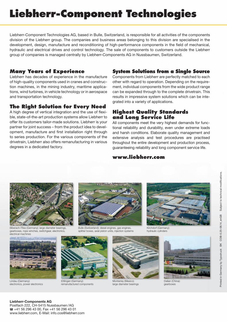
Liebherr-Component Technologies AG, based in Bulle, Switzerland, is responsible for all activities of the components division of the Liebherr group. The companies and business areas belonging to this division are specialised in the development, design, manufacture and reconditioning of high-performance components in the field of mechanical, hy draulic and electrical drives and control technology. The sale of components to customers outside the Liebherr group of companies is managed centrally by Liebherr-Components AG in Nussbaumen, Switzerland.
Biberach / Riss (Germany): large diameter bearings, gearboxes, rope winches, switchgear, electronics, electrical machines
Lindau (Germany): electronics, power electronics
Bulle (Switzerland): diesel engines, gas engines, splitter boxes, axial piston units, injection systems
Ettlingen (Germany): remanufactured components
Kirchdorf (Germany): hydraulic cylinders
Monterrey (Mexico): large diameter bearings
Many Years of ExperienceLiebherr has decades of experience in the manufacture of high-quality components used in cranes and construc-tion machines, in the mining industry, maritime applica-tions, wind turbines, in vehicle technology or in aerospace and transportation technology.
The Right Solution for Every NeedA high degree of vertical integration and the use of flexi-ble, state-of-the-art production systems allow Liebherr to offer its customers tailor-made solutions. Liebherr is your partner for joint success – from the product idea to devel-opment, manufacture and first installation right through to series production. For the various components of the drivetrain, Liebherr also offers remanufacturing in various degrees in a dedicated factory.
System Solutions from a Single SourceComponents from Liebherr are perfectly matched to each other with regard to operation. Depending on the require-ment, individual components from the wide product range can be expanded through to the complete drivetrain. This results in impressive system solutions which can be inte-grated into a variety of applications.
Highest Quality Standards and Long Service Life All components meet the very highest demands for func-tional reliability and durability, even under extreme loads and harsh conditions. Elaborate quality management and extensive analysis and test procedures are practised throughout the entire development and production process, guaranteeing reliability and long component service life.
www.liebherr.com
Dalian (China): gearboxes
Pri
nted
in G
erm
any
by
Typ
od
ruck
B
K
CO
B-0
.25
-08.
14_e
nGB
S
ubje
ct t
o te
chni
cal m
od
ifica
tions
.
Liebherr-Components AGPostfach 222, CH-5415 Nussbaumen / AG +41 56 296 43 00, Fax +41 56 296 43 01www.liebherr.com, E-Mail: [email protected]