planning and layout of small-stream diversions
TRANSCRIPT

Planning and layout of Small-Stream diverSionS
FOREST SERVICE
DEP A RTMENT OF AGRICU L T UR
E
United States Department of AgricultureForest Service
National Technology & Development Program • 2500—Watershed, Soil & Air Mgmt • 1325 1801—SDTDC • March 2013

Non-Discrimination Policy
The U.S. Department of Agriculture (USDA) prohibits discrimination against its customers, employees, and applicants for employment on the bases of race, color, national origin, age, disability, sex, gender identity, religion, reprisal, and where applicable, political beliefs, marital status, familial or parental status, sexual orientation, or all or part of an individual’s income is derived from any public assistance program, or protected genetic information in employment or in any program or activity conducted or funded by the Department. (Not all prohibited bases will apply to all programs and/or employment activities.)
To File and Employment Complaint
If you wish to file an employment complaint, you must contact your agency’s EEO Counselor (click the hyperlink for list of EEO Counselors) within 45 days of the date of the alleged discriminatory act, event, or in the case of a personnel action. Additional information can be found online at http://www.ascr.usda.gov/complaint_filing_file.html.
To File a Program Complaint
If you wish to file a Civil Rights program complaint of discrimination, complete the USDA Program Discrimination form, found online at http://www.ascr.usda.gov/complaint_filing_cust.html, or at any USDA office, or call (866) 632-9992 to request the form. You may also write a letter containing all of the information requested in the form. Send your completed complaint form or letter to us by mail at U.S. Department of Agriculture, Director, Office of Adjudication, 1400 Independence avenue, S.W., Washington, D.C. 20250-9410, by fax (202) 690-7442 or email at [email protected].
Persons with Disabilities
Individuals who are deaf, hard of hearing or have speech disabilities and you wish to file either an EEO or program complaint please contact USDA through the Federal Relay Service at (800) 877-8339 or (800) 845-6136 (in Spanish).
Persons with disabilities who wish to file a program complaint, please see information above on how to contact us by mail directly or by email. If you require alternative means of communication for program information (e.g., Braille, large print, audiotape, etc.) please contact USDA’s TARGET Center at (202) 720-2600 (voice and TDD).
The Forest Service, an agency of the U.S. Department of Agriculture (USDA), has developed this information for the guidance of its employees, its contractors, and its cooperating Federal and State agencies. The Forest Service assumes no responsibility for the interpretation or use of this information by anyone except its own employees. The use of trade, firm, or corporation names is for the information and convenience of the reader. Such use does not constitute an official endorsement or approval of any product or service to the exclusion of others that may be suitable.
The U.S. Department of Agriculture (USDA) prohibits discrimination in all its programs and activities on the basis of race, color, national origin, age, disability, and where applicable, sex, marital status, familial status, parental status, religion, sexual orientation, genetic information, political beliefs, reprisal, or because all or part of an individual’s income is derived from any public assistance program. (Not all prohibited bases apply to all programs.) Persons with disabilities who require alternative means for communication of program information (Braille, large print, audiotape, etc.) should contact USDA’s TARGET Center at (202) 720-2600 (voice and TDD). To file a complaint of discrimination, write USDA, Director, Office of Civil Rights, 1400 Independence Avenue, S.W., Washington, D.C. 20250-9410, or call (800) 795-3272 (voice) or (202) 720-6382 (TDD). USDA is an equal opportunity provider and employer.
Planning and layout of Small-Stream diverSionS
by
Dan S. AxnessMcMillen LLC, Boise, ID
with
Kim ClarkinSan Dimas Technology and Development Center, San Dimas CA


v
Acknowledgements ........................................................................................................................... vii
Chapter 1—Introduction 1.1 Purpose of the guide .............................................................................................................. 1
1.2 Anatomy of a diversion ........................................................................................................... 3
1.3 Why are we concerned about diversions? ............................................................................. 4
Chapter 2—Site Assessment and Objectives ................................................................................. 15
2.1 Step 1: Background information ........................................................................................... 16
2.2 Step 2: Evaluate existing conditions and identify site constraints ........................................ 18
2.3 Step 3: Survey the site ........................................................................................................ 22
2.4 Step 4: Set objectives ........................................................................................................... 29
Chapter 3—Headgates ...................................................................................................................... 35
3.1 Headgate types .................................................................................................................... 36
3.2 Headgate sizing ................................................................................................................... 44
Chapter 4—Diversion Structures: Weirs, Pumps, Infiltration Galleries 4.1 Weirs .................................................................................................................................... 45
4.1.1 Types of check structures ........................................................................................ 55
4.2 Pump stations ....................................................................................................................... 87
4.2.1 Types of pumps ........................................................................................................ 91
4.2.2 Pump operation and maintenance ........................................................................... 92
4.3 Infiltration galleries ............................................................................................................... 93
4.3.1 Infiltration gallery operation and maintenance ......................................................... 96
4.4 Toxic materials ...................................................................................................................... 96
4.5 Diversion structure applicability ............................................................................................ 97
Chapter 5—Fish Protection at Diversions 5.1 Fish screens and fish screen bypass systems ................................................................... 105
5.1.1 Fixed-plate screens .................................................................................................110
5.1.1.1 Cleaning systems for fixed-plate screens ...................................................112
5.1.2 Moving screens .......................................................................................................114
5.1.3 End-of-pipe screens ................................................................................................117
Table of Contents

vi
Planning and Layout of Small-Stream Diversions
5.1.4 Screen comparisons ...............................................................................................117
5.1.5 Common causes of screen failure .......................................................................... 123
5.1.6 Fish-screen bypasses ............................................................................................ 123
5.2 Upstream fish passage ....................................................................................................... 124
5.2.1 Relocating the diversion ......................................................................................... 124
5.2.2 Seminatural, open-channel fishways designed for a target fish ............................. 126
5.2.3 Fish ladders ............................................................................................................ 127
5.2.3.1 Denil and Alaska steep-pass fish ladders ................................................. 127
5.2.3.2 Pool-and-weir fish ladders ......................................................................... 128
5.2.3.3 Vertical-slot fish ladders ............................................................................ 130
Chapter 6—Flow Measurement ...................................................................................................... 133
6.1 Sharp-crested weirs ........................................................................................................... 135
6.2 Measuring flumes ............................................................................................................... 138
6.3 Submerged orifices ............................................................................................................ 143
Chapter 7—Operations, Monitoring, and Maintenance Plan ....................................................... 147
Glossary/Bibliography .................................................................................................................... 153
Appendix A—Site Assessment Checklist ..................................................................................... 159
Appendix B—Automating River Diversions .................................................................................. 167
SCADA systems for diversions .................................................................................................. 169
Constraints for automation and SCADA systems ...................................................................... 174
References ................................................................................................................................ 177

vii
Acknowledgements
This guide owes its existence to Dave Gloss, hydrologist on the Medicine Bow National Forest. In 2006, as a result of his work with irrigation diversions and their effects, he suggested the need for a technical guide to structures “capable of achieving desired stream flows below diversions.” The guide attempts to accomplish that objective by sharing experience with the diversion components that can, when properly designed and managed, regulate flows and protect stream and riparian resources. Other people with years of experience in diversion design also saw the need and engaged in the project. Rob Sampson and Clare Prestwich (U.S. Department of Agriculture, Natural Resources Conservation Service [NRCS]); Jeanine Castro (U.S. Department of the Interior, U.S. Fish and Wildlife Service); and Bob Kenworthy and Tim Page (U.S. Department of Agriculture, Forest Service) helped define the initial focus and organization. Rob Sampson’s review improved the guide’s handling of “nature-like” versus hydraulic design. Clare Prestwich coauthored appendix B, with additional help on that appendix from Stephen Smith and Peter Robinson. Kozmo Ken Bates also offered perspective on common diversion problems.
The following people responded to questions or helped improve the draft by reviewing and critiquing it:
Jeanne Rumps, Idaho Department of Fish and Game
Jean Thomas, National Water Rights and Uses
Mark Moulton, Sawtooth National Recreation Area
Bob Kenworthy, Tim Page, and Jim Nutt, Intermountain Region Adjudication Team
Bill Goodman, Intermountain Region Watershed Program
Christine Dingman, Ashley National Forest
Charles Condrat, Wasatch-Cache National Forest
Dave Gloss, Medicine Bow National Forest
Kathryn Boyer, NRCS West National Technical Support Center
Warren Colyer, Trout Unlimited
Rob Sampson, USDA NRCS, Idaho
Clarence Prestwich, USDA NRCS, Portland
Morton D. McMillen, McMillen LLC
Stephen W. Smith, Regenesis Management Group
Stan Bradshaw, Trout Unlimited
Peter M. Robinson, NRCS West National Technical Support Center
viii
Planning and Layout of Small-Stream Diversions
We are very grateful to those who contributed illustrations:
Christine Dingman, Ashley National Forest
Mark Moulton, Sawtooth National Recreation Area
Kathleen Frizel, Bureau of Reclamation
Jim Nutt, Intermountain Region, Instream Flow Program
Anne Marie Emory Miller, Henry’s Fork Foundation
Darrin Miller, U.S. Geological Survey
Warren Colyer, Trout Unlimited
Kozmo Ken Bates, Engineering Consultant, Olympia, WA
Matt Woodard, Trout Unlimited
Brian Hamilton, Bureau of Reclamation
Roger Ford, USDA NRCS, New Mexico
Graphics by Deborah Mucci, Forest Service, National Technology and Development Program, and Gerald Gregory.

1
Chapter 1—Introduction
Many surface water diversions are located on streams within the boundaries of the National Forest System of the Forest Service, an agency of the U.S. Department of Agriculture. These diversions serve many different uses, including crop and pasture irrigation; single home, tract, industrial, or municipal water supply; and hydropower. They are one part of our infrastructure that increasingly is stressing aquatic populations and habitats (Northcote 1998). To help protect stream ecosystems, more efficient water management and more attention to aquatic species passage at surface water diversions are becoming critical.
This guide serves as a reference for Forest Service personnel and water users evaluating options for diversion infrastructure and management on streams less than about 50 feet wide. Topics include layout, operation, and maintenance of structures for water diversion; water control and measurement; and structures for fish protection (fishways, ladders, screens). We will describe the pros and cons of different structure types, their maintenance requirements, relative construction costs, and common failure modes. The guide should give Forest Service field staff and water users the information they need to plan diversion systems that meet users’ water needs while protecting aquatic and riparian habitats and organisms to the greatest possible degree.
Figure 1.1—Jerry Bird, Forest Service Intermountain Region Ditch Bill program manager, and Peter Frick, diverter, discussing an existing diversion and possible upgrades. Wise River Ranger District, Beaverlodge National Forest, 2009.
1.1 PurPoSe of the guide
Cha
pter
1—
Intr
oduc
tion

2
Planning and Layout of Small-Stream Diversions
Forest Service staff should keep in mind that diversions entail several levels of authority and responsibility, both private and governmental. In the West, the water-rights holder, the local water master, and the State water resources agency are always involved. Other State and/or Federal regulatory and land management agencies may be involved, depending on the diversion’s location. For example, State wildlife management authorities; U.S. Department of the Interior, U.S. Fish and Wildlife Service; and U.S. Department of Commerce, National Oceanic Atmospheric Administration, National Marine Fisheries Service may all have authority in different situations.
Western State water laws provide water-right holders with a right to divert water in priority. Western water laws do not, however, provide access to the water with the water right. Rather, access to the water across the land of another is provided under State realty laws. In the case of Federal lands, access can only be provided under Federal law. Federal laws may mandate the imposition of terms and conditions to protect the Federal estate, including the aquatic and riparian resources and their dependent wildlife, such as fish, amphibians, and other aquatic species.
It has long been Forest Service policy that special use permits authorizing water diversion facilities located on National Forest System lands incorporate stipulations to protect aquatic habitat and/or maintain stream channel stability (Witte 2001). In fact, the Forest Land Policy and Management Act of 1976 requires such stipulations. The act states that before issuing an authorization for facilities to impound, store, transport, or distribute water on public lands, the Forest Service and U.S. Department of the Interior, Bureau of Land Management must impose terms and conditions that…”minimize damage to scenic and esthetic values and fish and wildlife habitat and otherwise protect the environment” (43 U.S.C. 1765). In addition, the Endangered Species Act requires Federal agencies to ensure that any action they authorize “...is not likely to jeopardize the continued existence of any endangered species or threatened species or result in the destruction or adverse modification of [designated critical] habitat.”
Diversion structures change the nature of a stream by ponding and diverting some water. Ideally, they are designed to remove water from the channel while passing sediment, woody debris, and fish beyond the structure. Most structures are effective in removing water, but they occasionally block sediment movement, accumulate debris, block fish passage in the main channel, entrain fish in the diversion ditch, or dewater the stream entirely.

3
Chapter 1—Introduction
Forest Service staff and water users can use this guide to assess existing diversions, identify problems at a site, and identify possible types of structural and operational improvements that might solve those problems. The guide is intended to facilitate interactions with a professional engineer/designer by familiarizing readers with diversion components and issues. It is not a substitute for an engineer experienced in diversion design. Diversions that provide the appropriate amount of water without burdensome operation and maintenance requirements AND adequately protect the aquatic system will almost always require design tailored to the site by an experienced engineer.
Diversions are comprised of some combination of the following (figure 1.2):
■ Diversion structure (e.g., dam, weir, and so forth).
■ Headgate, pump, or other water intake structure.
■ Ditch or pipe conveying diverted water to the point of use.
■ Fish screen and bypass channel returning fish to the stream.
■ Fishway for upstream fish passage.
■ Water measurement (and sometimes recording) device.
Where the control structure is located down-ditch (common, particularly in older structures), a wasteway channel is often included through which surplus water is returned to the source.
Figure 1.2—Typical layout and components of a diversion. This drawing demonstrates how the various parts of a diversion are located and related to each other. Not every diversion has all components.
1.2 anatomy of a diverSion

4
Planning and Layout of Small-Stream Diversions
In this guide, chapters 3 through 6 provide an overview of the common types of all of these components, the benefits and disadvantages of each, and sites or situations where each might best be used to limit detrimental effects on the aquatic environment. This information should help identify the best options for individual sites. Chapter 7 provides an overview of operations, monitoring, and maintenance actions commonly associated with diversion structures.
Chapter 2 describes the first steps in planning for new or upgraded diversions. These steps include gathering historical and environmental background information about the site and evaluating current conditions and problems.
Many diversions on National Forest System lands have been in place for decades and are still using manual techniques for water control. Many are in remote locations where headgates—if they exist—may or may not be adjusted in response to changing runoff, and ditch failures may not be noticed for days or weeks. Some diversions take water from streams with threatened and endangered species, and effects on the aquatic system are of high concern for that reason.
Diversions that are not well designed and operated can damage streams, aquatic and riparian habitats, and aquatic organisms in very important ways. None, one, or any combination of the following types of effects may be important at any specific site.
■ A diversion dam backwaters streamflow and can cause sediment deposition, especially if the dam is not removed or if sediment is not sluiced during high flows (figure 1.3). Upstream of the dam in the depositional area, the stream may be locally shallower and more prone to flood adjacent lands. The riparian water table may be higher. This could have two different effects: it could lengthen the duration of saturated, anaerobic conditions in the root zone, stunting growth, and diminishing the vitality of the riparian vegetation; or it could improve water availability, increasing the vigor of riparian vegetation (Bohn and King 2000). Local streambed material may be finer and more uniform than in the undisturbed channel, burying diverse, formerly aerobic habitats. In unentrenched reaches, where streambanks are not heavily vegetated, or where riparian shrubs have lost their ability to armor the banks, the channel may widen and/or shift position across the valley floor.
1.3 Why are We concerned about diverSionS?
Stream channel morphology and stability

5
Chapter 1—Introduction
Figure 1.3—Santa Margarita River O’Neil diversion weir at Camp Pendleton, CA. This steel pile dam is in a river with very high sediment load. Heavily vegetated sediment accumulations upstream and downstream are visible in this photo, which was taken shortly after a moderate flood had disturbed the channel. Photo by Kathleen Frizel, Bureau of Reclamation.
■ Streambed scour caused by water plunging over the dam crest (figure 1.4) can undermine and destabilize a poorly built dam. If the downcutting destabilizes the dam (for example, a nonengineered dam built of streambed materials) and a zone of channel bed erosion migrates upstream as a headcut, the dam and diversion inlet also must be moved upstream. In some cases, this has occurred many times, as the water user seeks the elevation needed to allow gravity flow into the ditch. Bates (2006) identified this as a relatively common reason for stream-reach dewatering in the Sawtooth National Recreation Area, and recommended that points of diversion be moved downstream where possible.
6
Planning and Layout of Small-Stream Diversions
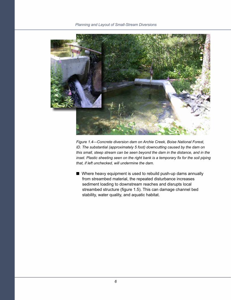
Figure 1.4—Concrete diversion dam on Archie Creek, Boise National Forest, ID. The substantial (approximately 5 foot) downcutting caused by the dam on this small, steep stream can be seen beyond the dam in the distance, and in the inset. Plastic sheeting seen on the right bank is a temporary fix for the soil piping that, if left unchecked, will undermine the dam.
■ Where heavy equipment is used to rebuild push-up dams annually from streambed material, the repeated disturbance increases sediment loading to downstream reaches and disrupts local streambed structure (figure 1.5). This can damage channel bed stability, water quality, and aquatic habitat.

7
Chapter 1—Introduction
Figure 1.5—Push-up wing dam, Salmon River, ID. Runoff from a wildfire area upstream is causing the turbidity here.

8
Planning and Layout of Small-Stream Diversions
■ Dams can be undermined by downcutting or piping, or toppled by the pressure of water. Dam failure, together with the headcutting likely to occur afterward, can produce enough sediment to affect aquatic habitat and water quality for some distance downstream.
■ Summer water temperatures can increase in slow-moving backwaters upstream of diversion dams. In the main channel downstream of the point of diversion, water temperature can increase dramatically when flow is so low that the exposed streambed heats up.
■ The decrease in instream flow due to water diversion reduces the area and depth of instream aquatic habitats (figure 1.6). It may also decrease the water available to downstream riparian vegetation, potentially affecting its vigor and productivity.
Figure 1.6—(A) Diversion for small hydropower project dramatically reduces flow in the channel at the right. Trail Creek, Middle Fork Ranger District, Salmon Challis National Forest, 2007. (B) Idaho’s Beaver Creek, dewatered by multiple irrigation diversions upstream, August 2001.
a
b
Water and aquatic habitat quality at risk

9
Chapter 1—Introduction
■ Where flow into the ditch was not well controlled in the past, there are cases where most streamflow now flows in the former ditch and the headgate has been moved downstream. This isolates a section of the natural channel, leaving it with little or no water at low flows (figure 1.7).
Figure 1.7—Hypothetical history of a poorly controlled diversion. The ditch captured the stream when the old headgate failed to prevent high flows from entering the ditch. The current stream channel is dry, and all flow is now in the former ditch, which is high on the valley sideslope. The current channel downstream of the diversion dam is therefore steep and could be impassable to fish that might be migrating upstream.
Aquatic organisms
10
Planning and Layout of Small-Stream Diversions
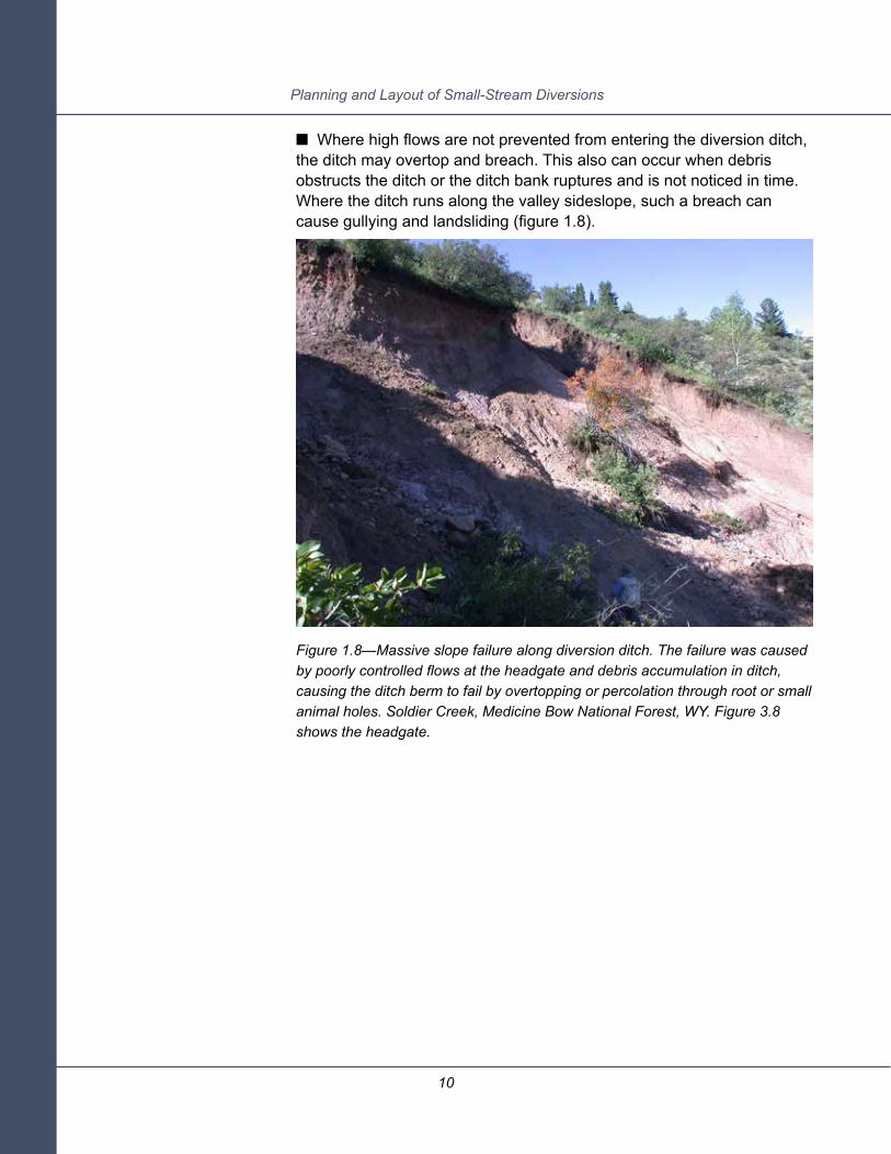
■ Where high flows are not prevented from entering the diversion ditch, the ditch may overtop and breach. This also can occur when debris obstructs the ditch or the ditch bank ruptures and is not noticed in time. Where the ditch runs along the valley sideslope, such a breach can cause gullying and landsliding (figure 1.8).
Figure 1.8—Massive slope failure along diversion ditch. The failure was caused by poorly controlled flows at the headgate and debris accumulation in ditch, causing the ditch berm to fail by overtopping or percolation through root or small animal holes. Soldier Creek, Medicine Bow National Forest, WY. Figure 3.8 shows the headgate.

11
Chapter 1—Introduction
■ Some diversion dams impede the upstream movement of swimming and crawling species (Schmetterling and Adams 2004), preventing fish and other aquatic organisms from finding spawning sites, food, refuge from warm water temperatures, and so forth (figure 1.9).
Figure 1.9—This diversion dam was a barrier to upstream passage of fish, including the chinook salmon shown here. The dam has since been removed. Alturas Lake Creek, ID.

12
Planning and Layout of Small-Stream Diversions
■ Fish can enter or be swept into the ditch and may be unable to return to the main channel (Gale et al. 2008) (figure 1.10).
Figure 1.10—(A) The unscreened Cross Cut Canal in the Henry’s Fork Snake River watershed entrains both game and nongame fish. Before the headgate is closed at the end of the crop season, the Henry’s Fork Foundation sweeps the ditch to salvage fish that would otherwise be stranded. In 2009, 116 rainbow, brook, and brown trout as well as 593 whitefish were salvaged from the first 100 meters below the headgate and returned to the river. (B) Juvenile salmonids were entrained in this ditch and stranded when the headgate was closed for the season, Salmon River, ID.
a
b

13
Chapter 1—Introduction
■ Small fish and other aquatic species can be swept onto and pinned against the surface of some types of fish screens. Boreal toads, which float downstream in summer, have been found dead in front of fish screens in Montana (Adams et al. 2005).
■ Fish in the main channel downstream of the diversion can be stranded when a headgate is opened if instream water elevations drop abruptly.
Some of the effects discussed above are direct, others are indirect, and all may be cumulative. Whether they are important or not depends, as always, on the situation. Where adverse effects are important, planners should determine what is necessary to protect aquatic and other resources, and then work with water users to achieve those goals. The diversion may need upgrades to improve water control, water use efficiency, or reduce effects on aquatic biota. Within the limits defined by Federal law, regulation, and policy, planners should try to optimize the Federal terms and conditions granting the access in a manner most beneficial for all.
Diversions are more than just the dam or diversion structure. They are interrelated systems of structures and management actions. General best management practices for protection of water quality at diversions and conveyances are outlined in “The Forest Service National Core Best Management Practices” (U.S. Department of Agriculture, Forest Service 2009). Each site, however, will have its own set of stream/site/water user characteristics and needs, and best practices will be to some degree site specific. Planning the best solution for each site requires understanding the aquatic, riparian, hydraulic, and management contexts. Then, an interdisciplinary team including the water user can select the structures, identify objectives, design the layout, and devise an operating plan that achieves the objectives. Again, for most diversions, an experienced diversion engineer on the team will be essential.
Summary


15
Chapter 2—Site Assessment and Objectives
15
This chapter guides users through a site assessment for evaluating diversion condition or considering modifications. The process can be broken into the following steps:
1. In the office, gather background information about the site.
a. Historical information about management of the existing diversion and other associated diversions.
b. Aquatic ecology.
i. Habitats upstream and downstream.
ii. Aquatic species use of those habitats: timing, importance, known issues.
c. Watershed hydrology and land uses (U.S. Geological Survey Stream Stats, impaired water body listing, watershed studies).
d. Projected future changes in water, sediment, woody debris loadings.
2. At the site, evaluate the current condition of the diversion installation and the channel. Identify site constraints and opportunities. Do this with the diverter, if possible.
3. Survey site topography and hydraulic infrastructure paying particular attention to existing water levels and historic watermarks.
4. Set objectives for the upgrade. Do this with an interdisciplinary team including the diverter and any other interested parties.
The background information (1) places the diversion in its management and environmental context. You will need it to interpret what you see in the field. It also is needed to develop well-founded objectives for any upgrade and to plan a structure that disrupts the aquatic system as little as possible.
The condition assessment (2) identifies and documents observable design and operations issues associated with the diversion. The site survey (3) produces basic channel data for the area above, at, and below the diversion that enables you to envision possible alternative improvements and helps in estimating their cost. Diversion structure improvements commonly benefit both fish and other aquatic organisms and water users, but they may be expensive and require outside funding. Together, the site survey and condition assessment can constitute documentation for applying for financial assistance for the upgrade,
Cha
pter
2—
Sit
e A
sses
smen
t an
d O
bjec
tive
s

16
Planning and Layout of Small-Stream Diversions
as well as communicating with a prospective engineer/designer. Most water users can take advantage of professional engineering design and financial assistance from the U.S. Department of Agriculture, Natural Resources Conservation Service (NRCS). Conservation district staff and qualified consulting engineers also can provide assistance.
In steps 1 through 3, one develops a familiarity with site history, resources and operations/maintenance issues, and current site conditions. From that base, a team can articulate a set of objectives for the site and the diversion upgrade in collaboration with the water user. The objectives will deal with multiple resource and operations and maintenance issues, which may conflict. The site survey and information on site constraints will help the team identify realistically implementable alternatives and recommend an optimal alternative. Alternatives often include moving the point of diversion, consolidating points of diversion to reduce maintenance, and improving water-use technology to reduce water demand.
Any in-channel work requires background information about the watershed, the history of the site, and the resources affected or at risk. Examples of this type of information are described by the Forest Service Stream-Simulation Working Group (FSSSWG 2008, chapter 4), and it is embedded in the preparation for stream restoration projects described in “Stream Corridor Restoration” (Federal Interagency Stream Corridor Working Group 2003). Some of the questions this work can answer include:
1. What are the social and natural resource values at or affected by the site? Values might include threatened and endangered aquatic species, critical aquatic habitats, other water supply infrastructure and cultural resources, nearby infrastructure, homes, and so forth.
2. What is the general geology and soil type (especially the soil texture—sandy, silty, clayey, rocky) in the area of the diversion?
3. What is the hydrologic regime (amount and timing of high and low flows, diversion flows)?
4. How frequently does the stream overflow onto its flood plain. If it does, risks, such as inundating the ditch headworks and eroding fill around the headgate, may become design considerations.
2.1 SteP 1: background information

17
Chapter 2—Site Assessment and Objectives
5. Does the stream transport large amounts of bed material that can deposit upstream of a dam?
6. What are the watershed-scale risk factors, if any? Risk factors might be such things as:
a. A large portion of the watershed was recently burned, or is at risk of burning.
b. The stream was destabilized by a large flood event and is still recovering.
c. Road development is increasing the tendency for flooding dur-ing summer thunderstorms.
d. The stream channel is actively downcutting downstream of the diversion, and the zone of active erosion is moving up-stream.
7. What natural or manmade fish movement barriers exist, particu-larly in streams with migratory fish?
Other useful background information for diversion planning includes:
1. What can you find out about the diversion’s management history? Agency records might show chronic ditch breakouts, permitting issues, changes in ownership, complaints about flooding caused by a temporary dam being left in place during high flow season, and so forth. The National Forest System Water Rights and Uses database should contain administrative data about the site and also may include some historical condition information.
2. What is the amount and timing of the diversion’s water use, and who owns the right?
3. Are there land ownership issues? Land ownership may be com-plex and/or property markers may be absent or imprecise near the point of diversion. Many diversions are near national forest bound-aries, and confidently determining land ownership may require a survey.
4. What other diversions and water rights exist upstream and down-stream? How do they relate to each other (including land owner-ship) and to conditions within the drainage and adjacent drainag-es? Understanding the big picture of water use in the drainage is

18
Planning and Layout of Small-Stream Diversions
crucial to planning effective improvements. For example, different points of diversion serving the same areas may be an opportunity for consolidation. Improved efficiency at one diversion may not im-prove aquatic habitat conditions if downstream junior water-rights holders increase their use.
5. How does the available water supply relate to irrigation or other water uses?
Keep in mind that streams may gain flow in some reaches (from natural sources or irrigation returns, and so forth) and lose flow in other reaches. A simple accounting of mean flow during the diversion season versus diverted flow may not present a realistic picture of water availability at any one point of diversion.
A reconnaissance walkthrough familiarizes you with the site and allows the diverter to explain how (s)he manages it, as well as operations and maintenance problems and needs for improvement. Use the opportunity to identify and talk over common problems, such as those in table 2.1. If the Forest Service Water Rights and Uses Site Visit form has been updated recently, this step may have been partly accomplished in the course of filling out that form.
Figure 2.1 —Where a permanent diversion structure is narrower than the bankfull channel, flow accelerating across the structure often scours a plunge pool immediately downstream, frequently causing bank erosion and fish passage problems. Cottonwood Creek, ID.
2.2 SteP 2: evaluate exiSting conditionS and identify Site conStraintS
Words and phrases shown in bold are
defined in the glossary.

19
Chapter 2—Site Assessment and Objectives
evi
denc
e
Silt
, san
d, a
nd g
rave
l for
m a
bar
ups
tream
of t
he s
truct
ure.
Sed
imen
t fills
the
conv
eyan
ce
ditc
h. S
edim
ent b
urie
s th
e w
ater
con
trol g
ates
or s
topl
ogs.
Cha
nnel
cap
acity
may
be
low
, ca
usin
g fre
quen
t ove
rban
k flo
odin
g.
Rec
onst
ruct
ion
of p
ushu
p da
ms
or a
ny o
ther
mai
nten
ance
of i
nstre
am s
truct
ures
with
hea
vy
equi
pmen
t can
cau
se a
n in
crea
se in
sed
imen
t loa
ding
. Loo
k fo
r diff
eren
ces
in s
edim
ent
depo
sitio
n be
twee
n up
stre
am a
nd d
owns
tream
reac
hes.
You
may
find
larg
er o
r mor
e ac
tive
bars
alo
ng th
e ba
nks
or m
idch
anne
l dow
nstre
am o
f the
div
ersi
on.
Som
etim
es a
mid
chan
nel g
rave
l bar
form
s do
wns
tream
of t
he d
iver
sion
stru
ctur
e, c
ausi
ng
eros
ion
on o
ne o
r bot
h ba
nks.
Dow
nstre
am c
hann
el b
otto
m is
sig
nific
antly
low
er th
an u
pstre
am c
hann
el b
otto
m, i
ndic
atin
g ch
anne
l inc
isio
n. A
dditi
on o
f sta
biliz
atio
n ro
ck, d
ebris
, or s
ever
al c
oncr
ete-
slab
lifts
or p
ours
is
an
indi
catio
n of
mai
nten
ance
act
iviti
es to
add
ress
this
issu
e. C
hann
el b
ed im
med
iate
ly
dow
nstre
am o
f che
ck s
truct
ure
may
be
coar
ser (
i.e.,
larg
er ro
ck) t
han
unaf
fect
ed s
tream
re
ache
s. T
his
can
happ
en w
hen
a da
m tr
aps
fine
sedi
men
t ups
tream
. By
the
time
the
dam
po
ol fi
lls w
ith s
edim
ent a
nd s
edim
ent b
egin
s to
mov
e do
wns
tream
, the
dow
nstre
am re
ach
may
ha
ve s
cour
ed a
nd d
eepe
ned
so m
uch
that
fine
sed
imen
t can
no
long
er b
e re
tain
ed.
Whe
re th
e di
vers
ion
stru
ctur
e is
nar
row
er th
an th
e ba
nkfu
ll ch
anne
l, or
whe
re w
ater
falls
from
an
exc
essi
ve h
eigh
t, a
scou
r hol
e m
ay h
ave
form
ed d
owns
tream
(figu
re 2
.1).
A he
adcu
t or n
ickp
oint
dow
nstre
am th
at is
mig
ratin
g up
stre
am c
an d
esta
biliz
e th
e di
vers
ion
by
low
erin
g st
ream
bed
elev
atio
n an
d un
derm
inin
g th
e st
ruct
ure.
Evi
denc
e of
a h
eadc
ut is
a lo
cal
stee
peni
ng o
f cha
nnel
gra
dien
t. D
epen
ding
on
how
con
solid
ated
or c
ohes
ive
the
bed
mat
eria
l is
, a h
eadc
ut m
ay e
xten
d ov
er a
dis
tanc
e of
sev
eral
cha
nnel
wid
ths
or it
may
be
rela
tivel
y ab
rupt
.
Pro
blem
Sedi
men
t dep
ositi
on.
Incr
ease
d se
dim
ent l
oadi
ng
to d
owns
trea
m c
hann
el.
Late
ral c
hann
el in
stab
ility
.
Eros
ion/
chan
nel i
ncis
ion/
head
cuts
/ str
eam
bed
scou
r/be
d de
grad
atio
n.
Tabl
e 2.
1—C
omm
on p
robl
ems
obse
rved
at d
iver
sion
stru
ctur
es

20
Planning and Layout of Small-Stream Diversions
Pro
blem
Stre
am c
hann
el d
ewat
ered
.
Elev
ated
wat
er te
mpe
ratu
re.
Lack
of r
ipar
ian
vege
tatio
n.
Acc
umul
atio
n of
shr
ubs,
tr
ees,
and
deb
ris a
long
ditc
h.
Aqu
atic
ani
mal
pas
sage
up
stre
am a
nd d
owns
trea
m.
Deb
ris o
r sed
imen
t ac
cum
ulat
ion
at d
iver
sion
.
evi
denc
e
The
dive
rsio
n m
ay re
mov
e m
ost o
f the
wat
er fr
om th
e st
ream
cha
nnel
, lea
ving
the
chan
nel
dow
nstre
am d
ewat
ered
for m
iles.
Veg
etat
ion
may
be
encr
oach
ing
in th
e do
wns
tream
cha
nnel
. In
som
e ca
ses,
sub
stan
tial d
ewat
erin
g on
ly o
ccur
s up
stre
am o
f a w
aste
way
or fi
sh b
ypas
s ch
anne
l out
let.
In th
is c
ase,
layo
ut a
nd/o
r hea
dgat
e ch
ange
s m
ay m
ake
it po
ssib
le to
redu
ce
the
amou
nt o
f wat
er d
iver
ted
abov
e th
e by
pass
to m
aint
ain
habi
tat a
nd a
quat
ic s
peci
es
pass
age.
Rem
oval
of l
arge
am
ount
s of
wat
er a
t a d
iver
sion
can
incr
ease
the
effe
ct o
f sol
ar e
xpos
ure
and
bed
heat
ing
on th
e re
mai
ning
wat
er, s
o th
at s
tream
tem
pera
ture
pro
gres
sive
ly in
crea
ses
dow
nstre
am o
f the
div
ersi
on. A
lso,
bac
kwat
erin
g m
ay c
ause
an
incr
ease
in s
tream
te
mpe
ratu
re a
bove
a d
am.
Ban
k di
stur
banc
e, e
rosi
on, h
igh
wat
er ta
bles
, or d
ewat
erin
g ca
n al
l wea
ken
bank
veg
etat
ion.
Th
is m
ay c
ontri
bute
to p
oor s
ecur
ity c
over
for fi
sh, p
oor f
orag
e ba
se (f
rom
inse
ct a
nd le
af
drop
), an
d el
evat
ed w
ater
tem
pera
ture
s.
Live
or d
ead
shru
bs, t
rees
, or d
ebris
obs
truct
ing
flow
s or
cat
chin
g de
bris
in d
itch.
Tre
es a
nd
deep
-roo
ted
shru
bs c
an c
ontri
bute
to le
aks
or b
reak
s in
ditc
hes
thro
ugh
hole
s le
ft w
hen
root
s di
e, tr
eeth
row
, sm
all a
nim
al b
urro
ws,
and
ice
dam
s in
sha
ded
area
s.
Div
ersi
ons
can
bloc
k sw
imm
ing
spec
ies
pass
age
in b
oth
upst
ream
and
dow
nstre
am
dire
ctio
ns. U
pstre
am p
assa
ge c
an b
e bl
ocke
d by
ver
tical
dro
ps th
at e
xcee
d th
e ju
mpi
ng a
bilit
y of
the
loca
l aqu
atic
spe
cies
or b
y st
ream
flow
that
is to
o fa
st o
r too
sha
llow
to s
wim
or c
raw
l th
roug
h (fi
gure
1.9
). D
owns
tream
pas
sage
can
be
bloc
ked
whe
n th
e di
vers
ion
rem
oves
all
of
the
wat
er fr
om th
e st
ream
cha
nnel
or w
hen
aqua
tic o
rgan
ism
s ar
e sw
ept i
nto
the
ditc
h w
ithou
t a
way
to re
ente
r the
mai
n ch
anne
l. P
iles
of s
edim
ent a
nd/o
r deb
ris in
vic
inity
of a
dam
.
Tabl
e 2.
1 —C
omm
on p
robl
ems
obse
rved
at d
iver
sion
stru
ctur
es (c
ontin
ued)

21
Chapter 2—Site Assessment and ObjectivesTa
ble
2.1 —
Com
mon
pro
blem
s ob
serv
ed a
t div
ersi
on s
truct
ures
(con
tinue
d)
Pro
blem
Inad
equa
te w
ater
con
trol
.
Ditc
h fa
ilure
s.
Fish
ent
rain
men
t in
ditc
h.
Ope
ratio
n an
d m
aint
enan
ce.
Vand
alis
m.
evi
denc
e
No
head
gate
.H
eadg
ate
not l
ocke
d.G
ullie
s do
wns
lope
from
ditc
h ov
erflo
w.
Stre
am c
hann
el d
iver
ted
dow
n di
tch.
Poo
rly c
ontro
lled
dive
rsio
n st
ruct
ures
and
hea
dgat
es o
ften
allo
w e
xces
s w
ater
to ru
n do
wn
the
ditc
h. T
he d
itch
may
ove
rtop
the
bank
s an
d er
ode
a gu
lly b
ack
to th
e st
ream
cha
nnel
(figu
re
3.1)
. Gul
lies
that
sta
rt at
or b
elow
the
ditc
h an
d re
pair
wor
k to
ditc
h ba
nks
are
stro
ng in
dica
tors
th
at o
verto
ppin
g or
pip
ing
has
occu
rred
or i
s on
goin
g. U
nscr
eene
d di
vers
ions
are
like
ly to
ent
rain
fish
. Som
etim
es, p
artic
ular
ly w
hen
a di
vers
ion
is
bein
g sh
ut d
own,
fish
can
be
seen
con
greg
atin
g ju
st d
owns
tream
of t
he h
eadg
ate
unab
le to
re
ente
r the
mai
n ch
anne
l (fig
ure
1.10
a).
Tarp
s, h
ay b
ales
, pla
stic
, and
boa
rds
left
in a
ll ye
ar lo
ng a
re e
vide
nce
of o
pera
tion
and
mai
nten
ance
pro
blem
s. S
palle
d or
ero
ded
conc
rete
, rot
ten
woo
d, a
nd c
orro
ded
or b
ent m
etal
al
so a
re e
vide
nce
of p
robl
ems.
Dis
cuss
ions
with
irrig
ator
s of
ten
reve
al o
ngoi
ng o
pera
tion
and
mai
nten
ance
issu
es w
hich
may
requ
ire fr
eque
nt m
aint
enan
ce a
ctiv
ities
.
Infla
tabl
e bl
adde
r dam
s ha
ve o
ccas
iona
lly b
een
slas
hed.
Div
ersi
on o
utle
ts a
re p
lugg
ed b
y de
bris
and
tarp
s.

22
Planning and Layout of Small-Stream Diversions
Site Constraints. Almost all diversion structures have constraints related to the existing site topography, geology, land ownership, and other site infrastructure, among other things. It is important to identify where site constraints occur and what limitations they may place on improvements to the diversion structure. Site constraints can be obvious, such as where bedrock is exposed in the streambed, or they may be more subtle. Not uncommonly, a road may run upslope of and parallel to the stream, and one or more road drainage culverts may directly contribute to the diversion ditch. Runoff from side drainages and hillslopes also may be captured by the ditch, possibly delivering water and sediment that can damage fish screens and water measurement devices, even potentially block or overflow the ditch. Solving this kind of problem might involve relocating the fish screen or diversion structure or rerouting the road drainage.
Downstream conditions that can constrain diversion upgrades include a downstream headcut actively eroding the channel bed or fine-grained bed material likely to erode when subjected to water plunging over a dam. Another example is an undersized road-crossing culvert some distance downstream that backs water up far enough to reach the diversion during high flows. Backwatering the site can reduce the velocity of water sweeping debris off the screen, plugging the screen and reducing the amount of water diverted.
Potential upstream constraints include important features that cannot be inundated by backwater caused by the diversion, such as other diversion structures, homes, roads, or vegetation. Table 2.2 lists a number of common site constraints.
A basic set of measurements provides enough information to identify major issues, establish objectives, develop one or more conceptual designs to achieve those objectives, estimate approximate cost, and support an application for financial assistance for the upgrade.
For the survey, establish a temporary but stable benchmark (a location that can be relocated and measured from at a later date). Common temporary benchmarks include a paint mark on a large rock or diversion structure corner, a stake or pin, or a nail in a post or tree.
2.3 SteP 3: Survey the Site

23
Chapter 2—Site Assessment and Objectives
Potential Constraint on Diversion Location, Layout, and/or Design
Bedrock is the most obvious site constraint. It is expensive to cut/excavate and therefore controls the shape of the structures built on it. Boulder structures are challenging to stabilize on bedrock. Sand, silt, and clay also offer engineering challenges. Sandy and silty materials are susceptible to erosion and seepage, while clayey soils can exert tremendous forces against walls. Ground water returning to the surface can cause localized erosion around a diversion structure or ditch, destabilizing the structures.
A stream that is well connected to a wide flood plain (e.g., some Rosgen C or E channels) may need a diversion structure that tolerates overtopping and flooding. A diversion structure in a channel constrained in a steeper canyon (Rosgen A or B) may not need to tolerate overtopping, but instream wood and large amounts of sediment transported during flood events may influence structure selection.
Gauging stations, bridges, buildings, water control structures, fish screens, and ladders all may constrain the footprint of the diversion system.
Land ownership may limit access for construction and/or maintenance. Adjacent landowners may not allow moving a diversion structure onto their land.
Relocating a ditch or diversion structure may not be feasible where a historic structure or site would be disturbed. In addition, certain irrigation supply systems have historic importance, which may complicate permitting for improvement projects.
Weak vegetation (overgrazed, weed infested, no trees where needed) affects diversion-system design where the area is susceptible to erosion from overbank flooding and localized runoff. Such areas need a planting and/or vegetation management plan to improve the vegetation’s ability to control erosion.
Protecting habitat and security of threatened and endangered species and species of concern sometimes warrants methods that limit site access, timing of work, and the diversion footprint.
Table 2.2—Common diversion installation constraints
Condition
Geology/Soils
Stream Type
Structures
Land Ownership
Archaeology
Vegetation
Aquatic and Terrestrial Biota

24
Planning and Layout of Small-Stream Diversions
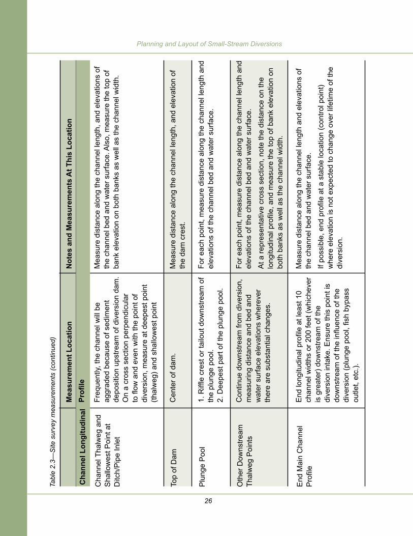
Channel bed and water surface elevations along the channel and ditch are key pieces of data for this preliminary survey. When elevations are plotted against distance along the channel, the resulting longitudinal profile indicates slope, important changes in slope, and the direction of waterflow (figure 2.2). The full range of flow conditions—low to high—is important to document on the longitudinal profile and on a plan view sketch. Use a nearby gauging station if available, a Stream Stats estimate for ungauged sites, or enlist the help of the landowner/diverter to estimate water surface elevations during low and very high flows. Look for clues, such as sediment deposited during high flows, or changes in vegetation type that might indicate a different frequency of inundation. Even if the diversion is not operable during high flows, flood elevations are important because the installation must be designed to avoid floodwaters entering the diversion ditch. Measuring the elevation of the stream bottom and the stream water surface elevation when the diversion is operating provides the information needed to calculate the control gate size capable of delivering the desired diversion flow.
In the main channel, the longitudinal profile connects points along the thread of deepest flow (the thalweg). If possible, start and end the profile at control points downstream and upstream of the diversion. Control points are locations where streambed elevation is unlikely to change, such as a rock outcropping, culvert, or another diversion structure. Channel bed elevation data should be gathered for at least 10 channel widths upstream and downstream or 200 feet, whichever is greater. Sketch the surveyed section, and annotate survey points.
At various points along the longitudinal profile, measure channel widths and elevation of the top of the banks. Measuring low and high streambank elevations and channel widths provides information needed to calculate wall heights and provide sufficient flow capacity in the structure.
Table 2.3 describes what to measure and where, and figure 2.2 identifies the survey points in a typical diversion. A site assessment form is included in appendix A.

25
Chapter 2—Site Assessment and ObjectivesTa
ble
2.3—
Site
sur
vey
mea
sure
men
ts
Not
es a
nd M
easu
rem
ents
At T
his
Loca
tion
If po
ssib
le, b
egin
pro
file
at a
sta
ble
loca
tion
(con
trol p
oint
) w
here
ele
vatio
n is
not
exp
ecte
d to
cha
nge
over
life
time
of th
e di
vers
ion.
Mea
sure
the
chan
nel b
ed e
leva
tion
at th
e de
epes
t poi
nt a
cros
s th
e ch
anne
l (th
alw
eg) a
nd th
e w
ater
sur
face
at t
hat p
oint
.
For e
ach
poin
t, m
easu
re d
ista
nce
alon
g th
e ch
anne
l len
gth
and
elev
atio
ns o
f the
cha
nnel
bed
and
wat
er s
urfa
ce.
Obs
erve
and
not
e be
d m
ater
ial s
izes
and
app
aren
t mob
ility
. A
re th
ere
fresh
sur
face
s on
any
gra
vels
, cob
bles
, or b
ould
ers?
O
r are
vis
ible
sur
face
s w
eath
ered
? Is
the
bed
mat
eria
l im
bric
ated
?
At a
cro
ss s
ectio
n w
here
ban
k he
ight
is re
pres
enta
tive
of
the
reac
h, n
ote
the
dist
ance
on
the
long
itudi
nal p
rofil
e, a
nd
mea
sure
the
top-
of-b
ank
elev
atio
n on
bot
h ba
nks.
Als
o m
easu
re c
hann
el w
idth
s at
thes
e cr
oss
sect
ions
(top
-of-b
ank
to
top-
of-b
ank)
.
Iden
tify
loca
tions
whe
re h
igh
wat
erm
arks
are
vis
ible
on
or n
ear
the
bank
s. T
hese
mig
ht b
e de
bris
line
s or
hig
h w
ater
mar
ks
on a
wal
l, fe
nce,
or t
rees
. Des
crib
e th
e hi
gh w
ater
mar
ks a
nd
mea
sure
thei
r ele
vatio
n. L
ando
wne
rs a
nd w
ater
use
rs m
ay b
e ab
le to
offe
r inf
orm
atio
n ab
out t
he h
ighe
st w
ater
see
n at
the
site
.
Cha
nnel
Lon
gitu
dina
l
Sta
rt M
ain
Cha
nnel
P
rofil
e
Oth
er U
pstre
am P
oint
s
Mea
sure
men
t Loc
atio
n
Profi
le
As
a ru
le o
f thu
mb,
beg
in lo
ngitu
dina
l pr
ofile
at l
east
10
chan
nel w
idth
s or
200
feet
(whi
chev
er is
gre
ater
) up
stre
am o
f the
div
ersi
on in
take
. E
nsur
e th
is p
oint
is u
pstre
am o
f the
in
fluen
ce o
f the
div
ersi
on.
Con
tinue
dow
nstre
am to
war
d di
vers
ion,
taki
ng m
easu
rem
ents
w
here
ver t
here
are
sub
stan
tial b
ed
elev
atio
n ch
ange
s or
mor
phol
ogic
al
chan
ges
with
in th
e st
ream
(poo
ls,
riffle
s, ru
ns, e
tc.).
Be
sure
to m
easu
re
at fi
shw
ay e
ntra
nce,
byp
ass
outle
t, or
oth
er k
ey p
oint
s re
late
d to
the
inst
alla
tion.
26
Planning and Layout of Small-Stream DiversionsTa
ble
2.3—
Site
sur
vey
mea
sure
men
ts (c
ontin
ued)
Not
es a
nd M
easu
rem
ents
At T
his
Loca
tion
Mea
sure
dis
tanc
e al
ong
the
chan
nel l
engt
h, a
nd e
leva
tions
of
the
chan
nel b
ed a
nd w
ater
sur
face
. Als
o, m
easu
re th
e to
p of
ba
nk e
leva
tion
on b
oth
bank
s as
wel
l as
the
chan
nel w
idth
.
Mea
sure
dis
tanc
e al
ong
the
chan
nel l
engt
h, a
nd e
leva
tion
of
the
dam
cre
st.
For e
ach
poin
t, m
easu
re d
ista
nce
alon
g th
e ch
anne
l len
gth
and
elev
atio
ns o
f the
cha
nnel
bed
and
wat
er s
urfa
ce.
For e
ach
poin
t, m
easu
re d
ista
nce
alon
g th
e ch
anne
l len
gth
and
elev
atio
ns o
f the
cha
nnel
bed
and
wat
er s
urfa
ce.
At a
repr
esen
tativ
e cr
oss
sect
ion,
not
e th
e di
stan
ce o
n th
e lo
ngitu
dina
l pro
file,
and
mea
sure
the
top
of b
ank
elev
atio
n on
bo
th b
anks
as
wel
l as
the
chan
nel w
idth
.
Mea
sure
dis
tanc
e al
ong
the
chan
nel l
engt
h an
d el
evat
ions
of
the
chan
nel b
ed a
nd w
ater
sur
face
.
If po
ssib
le, e
nd p
rofil
e at
a s
tabl
e lo
catio
n (c
ontro
l poi
nt)
whe
re e
leva
tion
is n
ot e
xpec
ted
to c
hang
e ov
er li
fetim
e of
the
dive
rsio
n.
Mea
sure
men
t Loc
atio
n Pr
ofile
Freq
uent
ly, th
e ch
anne
l will
be
aggr
aded
bec
ause
of s
edim
ent
depo
sitio
n up
stre
am o
f div
ersi
on d
am.
On
a cr
oss
sect
ion
perp
endi
cula
r to
flow
and
eve
n w
ith th
e po
int o
f di
vers
ion,
mea
sure
at d
eepe
st p
oint
(th
alw
eg) a
nd s
hallo
wes
t poi
nt
Cen
ter o
f dam
.
1. R
iffle
cres
t or t
ailo
ut d
owns
tream
of
the
plun
ge p
ool.
2. D
eepe
st p
art o
f the
plu
nge
pool
.
Con
tinue
dow
nstre
am fr
om d
iver
sion
, m
easu
ring
dist
ance
and
bed
and
w
ater
sur
face
ele
vatio
ns w
here
ver
ther
e ar
e su
bsta
ntia
l cha
nges
.
End
long
itudi
nal p
rofil
e at
leas
t 10
chan
nel w
idth
s or
200
feet
(whi
chev
er
is g
reat
er) d
owns
tream
of t
he
dive
rsio
n in
take
. Ens
ure
this
poi
nt is
do
wns
tream
of t
he in
fluen
ce o
f the
di
vers
ion
(plu
nge
pool
, fish
byp
ass
outle
t, et
c.).
Cha
nnel
Lon
gitu
dina
l
Cha
nnel
Tha
lweg
and
S
hallo
wes
t Poi
nt a
t D
itch/
Pip
e In
let
Top
of D
am
Plu
nge
Poo
l
Oth
er D
owns
tream
Th
alw
eg P
oint
s
End
Mai
n C
hann
el
Pro
file

27
Chapter 2—Site Assessment and Objectives
Mea
sure
men
t Loc
atio
n
Ele
vatio
n th
at c
ontro
ls w
ater
ent
erin
g th
e di
tch
or p
ipe.
Dim
ensi
ons
of h
eadg
ate
or d
itch
inle
t.
100
feet
to 2
00 fe
et d
owns
tream
of
head
gate
.
Not
es a
nd M
easu
rem
ents
At T
his
Loca
tion
Mea
sure
pip
e or
hea
dgat
e in
vert
or d
itch
botto
m, w
ater
su
rface
, and
top
of b
ank
elev
atio
ns.
Als
o m
easu
re a
vera
ge d
itch
wid
th (t
op-o
f-ban
k to
top-
of-b
ank)
ab
out 2
0 fe
et d
owns
tream
of h
eadg
ate
or p
ipe
outle
t.
Leng
th, h
eigh
t, di
amet
er o
f hea
dgat
e.
Mea
sure
ditc
h bo
ttom
, wat
er s
urfa
ce, a
nd to
p of
ban
k el
evat
ions
.
Als
o m
easu
re d
itch
wid
th (t
op-o
f-ban
k to
top-
of-b
ank)
.
Tabl
e 2.
3—S
ite s
urve
y m
easu
rem
ents
(con
tinue
d)
Div
ersi
on D
itch
Ditc
h In
let
Ditc
h In
let/H
eadg
ate
Ditc
h S
lope

28
Planning and Layout of Small-Stream Diversions
Figu
re 2
.2—
Exa
mpl
e pl
an a
nd lo
ngitu
dina
l pro
file
of e
xist
ing
dive
rsio
n st
ruct
ure.
Thi
s pl
an v
iew
sho
ws
cont
our l
ines
from
a to
tal-s
tatio
n su
rvey
, bu
t a c
aref
ul s
ketc
h in
dica
ting
surv
ey p
oint
s an
d an
y ot
her i
mpo
rtant
feat
ures
is a
ll th
at is
nee
ded
at th
e pl
anni
ng s
tage
. Add
to th
e sk
etch
ob
serv
atio
ns o
f hig
h flo
w li
nes,
ero
sion
, sed
imen
tatio
n, a
nd s
o fo
rth.

29
Chapter 2—Site Assessment and Objectives
While collecting elevation data, consider diversion structure design alternatives. Is the ditch steep enough to place a fish screen and/or water measurement device? What kind of diversion structure might be built that will deliver the water and provide fish passage while limiting backwatering, sediment deposition, upstream flooding, and channel instability?
Here is one example of a change that works in some circumstances.
If the channel has degraded (eroded vertically) downstream of the diversion, finding another site may be worthwhile. Upstream, the stream water surface is higher, so that a lower diversion dam can produce the head needed to deliver water to the ditch or pipeline. Moving diversions upstream (especially on steeper streams) can be an effective method of reducing problems with fish passage and erosion by reducing the elevation difference across the diversion structure. Often, piping the ditch for some distance downstream of the point of diversion allows for a lower diversion structure because a pipe has less resistance to flow than an unmaintained ditch, so the diversion can function with lower head. Piping also allows you to backfill the ditch, which reduces the risk of stream capture by the ditch.
There are tradeoffs, however; moving a ditch intake upstream lengthens the ditch and the length of dewatered stream channel. Whether the tradeoff is worthwhile will depend on how much the ditch would be lengthened, how much the stream is dewatered, and how much the new location would reduce fish passage or other problems. Land ownership also can change along the channel and this may make a move infeasible.
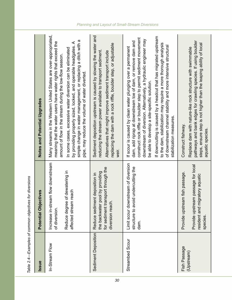
Depending on site conditions and management goals, objectives for the diversion installation may include any of the objectives listed on table 2.4. This is not an exhaustive list; an interdisciplinary team including the irrigator should assess the issues and set site-specific objectives. Some objectives may conflict with each other, and may need prioritization. Examples in table 2.4 include issues and objectives related to the stream, aquatic organisms, and operation and maintenance. Operation and maintenance issues should and do influence the objectives of diversion structure upgrades.
2.4 SteP 4: Set objectiveS
30
Planning and Layout of Small-Stream Diversions
Not
es a
nd P
oten
tial U
pgra
des
Man
y st
ream
s in
the
Wes
tern
Uni
ted
Sta
tes
are
over
-app
ropr
iate
d,
mea
ning
that
the
wat
er u
sers
hav
e w
ater
righ
ts th
at e
xcee
d th
e am
ount
of fl
ow in
the
stre
am d
urin
g th
e lo
w-fl
ow s
easo
n.
In s
ome
case
s, e
xces
sive
wat
er d
iver
sion
can
be
elim
inat
ed
by p
rovi
ding
pro
perly
siz
ed, l
ocke
d, a
nd o
pera
ble
head
gate
s. A
si
mpl
e ch
ange
in w
ater
man
agem
ent,
or re
plac
ing
a di
tch
with
a
pipe
, may
redu
ce th
e vo
lum
e of
wat
er d
iver
ted.
Sed
imen
t dep
ositi
on u
pstre
am is
cau
sed
by s
low
ing
the
wat
er a
nd
redu
cing
the
stre
am p
ower
ava
ilabl
e to
tran
spor
t sed
imen
t.
Alte
rnat
ives
that
mig
ht im
prov
e se
dim
ent t
rans
port
incl
ude
repl
acin
g th
e da
m w
ith a
rock
riffl
e, b
ould
er s
tep,
or a
djus
tabl
e w
eir.
If sc
our i
s ca
used
by
clea
n w
ater
plu
ngin
g ov
er a
per
man
ent
dam
, add
ripr
ap a
t dow
nstre
am to
e of
dam
, or r
emov
e da
m a
nd
cons
truct
rock
riffl
e or
bou
lder
ste
p to
per
mit
sedi
men
t mov
emen
t do
wns
tream
of d
iver
sion
. Alte
rnat
ivel
y, a
hyd
raul
ic e
ngin
eer m
ay
be a
ble
to d
evel
op a
site
-spe
cific
sol
utio
n.
If do
wnc
uttin
g is
cau
sed
by a
hea
dcut
that
has
mig
rate
d up
stre
am
to th
e da
m, s
tabi
lizat
ion
may
requ
ire a
mor
e th
orou
gh a
naly
sis
of d
owns
tream
cha
nnel
sta
bilit
y an
d m
ore
inte
nsiv
e st
ruct
ural
st
abili
zatio
n m
easu
res.
Con
stru
ct fi
shw
ay.
Rep
lace
dam
with
nat
ure-
like
rock
stru
ctur
e w
ith s
wim
mab
le
path
way
s an
d ba
nk e
dges
for c
raw
ling
spec
ies.
If u
sing
bou
lder
st
eps,
ens
ure
step
is n
ot h
ighe
r tha
n th
e le
apin
g ab
ility
of l
ocal
aq
uatic
spe
cies
.
Issu
e
In-S
tream
Flo
w
Sed
imen
t Dep
ositi
on
Stre
ambe
d S
cour
Fish
Pas
sage
(U
pstre
am)
Pote
ntia
l Obj
ectiv
es
Incr
ease
in-s
tream
flow
dow
nstre
am
of d
iver
sion
.
Red
uce
degr
ee o
f dew
ater
ing
in
affe
cted
stre
am re
ach
Red
uce
sedi
men
t dep
ositi
on in
th
e ba
ckw
ater
poo
l by
prov
idin
g fo
r sed
imen
t tra
nspo
rt th
roug
h th
e di
vers
ion
reac
h.
Lim
it sc
our d
owns
tream
of d
iver
sion
st
ruct
ure
to a
void
und
ercu
tting
the
dam
.
Pro
vide
ups
tream
fish
pas
sage
.
Pro
vide
ups
tream
pas
sage
for l
ocal
re
side
nt a
nd m
igra
tory
aqu
atic
sp
ecie
s.
Tabl
e 2.
4—E
xam
ples
of c
omm
on o
bjec
tives
for d
iver
sion
s
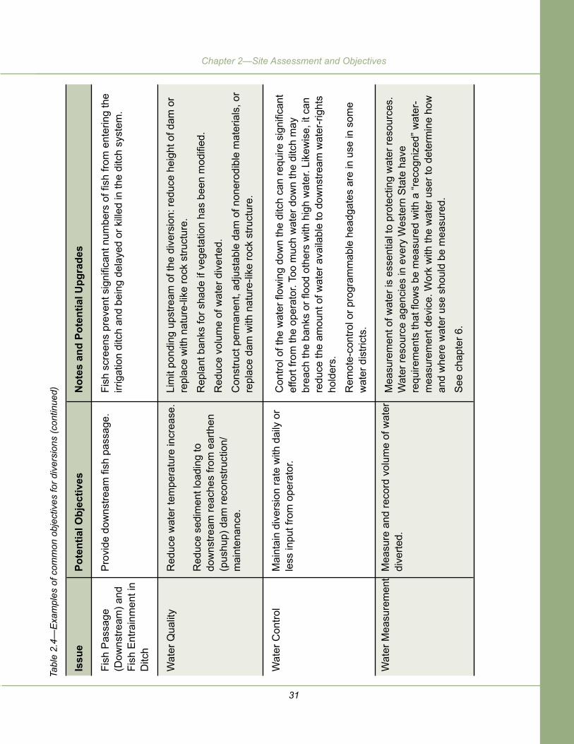
31
Chapter 2—Site Assessment and Objectives
Issu
e
Fish
Pas
sage
(D
owns
tream
) and
Fi
sh E
ntra
inm
ent i
n D
itch
Wat
er Q
ualit
y
Wat
er C
ontro
l
Wat
er M
easu
rem
ent
Pote
ntia
l Obj
ectiv
es
Pro
vide
dow
nstre
am fi
sh p
assa
ge.
Red
uce
wat
er te
mpe
ratu
re in
crea
se.
Red
uce
sedi
men
t loa
ding
to
dow
nstre
am re
ache
s fro
m e
arth
en
(pus
hup)
dam
reco
nstru
ctio
n/m
aint
enan
ce.
Mai
ntai
n di
vers
ion
rate
with
dai
ly o
r le
ss in
put f
rom
ope
rato
r.
Mea
sure
and
reco
rd v
olum
e of
wat
er
dive
rted.
Not
es a
nd P
oten
tial U
pgra
des
Fish
scr
eens
pre
vent
sig
nific
ant n
umbe
rs o
f fish
from
ent
erin
g th
e irr
igat
ion
ditc
h an
d be
ing
dela
yed
or k
illed
in th
e di
tch
syst
em.
Lim
it po
ndin
g up
stre
am o
f the
div
ersi
on: r
educ
e he
ight
of d
am o
r re
plac
e w
ith n
atur
e-lik
e ro
ck s
truct
ure.
Rep
lant
ban
ks fo
r sha
de if
veg
etat
ion
has
been
mod
ified
.
Red
uce
volu
me
of w
ater
div
erte
d.
Con
stru
ct p
erm
anen
t, ad
just
able
dam
of n
oner
odib
le m
ater
ials
, or
repl
ace
dam
with
nat
ure-
like
rock
stru
ctur
e.
Con
trol o
f the
wat
er fl
owin
g do
wn
the
ditc
h ca
n re
quire
sig
nific
ant
effo
rt fro
m th
e op
erat
or. T
oo m
uch
wat
er d
own
the
ditc
h m
ay
brea
ch th
e ba
nks
or fl
ood
othe
rs w
ith h
igh
wat
er. L
ikew
ise,
it c
an
redu
ce th
e am
ount
of w
ater
ava
ilabl
e to
dow
nstre
am w
ater
-rig
hts
hold
ers.
Rem
ote-
cont
rol o
r pro
gram
mab
le h
eadg
ates
are
in u
se in
som
e w
ater
dis
trict
s.
Mea
sure
men
t of w
ater
is e
ssen
tial t
o pr
otec
ting
wat
er re
sour
ces.
W
ater
reso
urce
age
ncie
s in
eve
ry W
este
rn S
tate
hav
e re
quire
men
ts th
at fl
ows
be m
easu
red
with
a “r
ecog
nize
d” w
ater
-m
easu
rem
ent d
evic
e. W
ork
with
the
wat
er u
ser t
o de
term
ine
how
an
d w
here
wat
er u
se s
houl
d be
mea
sure
d.
See
cha
pter
6.
Tabl
e 2.
4—E
xam
ples
of c
omm
on o
bjec
tives
for d
iver
sion
s (c
ontin
ued)

32
Planning and Layout of Small-Stream Diversions
Issu
e
Deb
ris a
nd/o
r S
edim
ent R
emov
al
Free
zing
Con
ditio
ns
Div
ersi
on D
urab
ility
Pote
ntia
l Obj
ectiv
es
Pro
vide
saf
e an
d ec
onom
ical
ap
proa
ches
to re
mov
e de
bris
and
/or
sedi
men
t.
Pro
vide
saf
e an
d ec
onom
ical
ap
proa
ch to
ope
rate
div
ersi
on d
urin
g fre
ezin
g co
nditi
ons.
Pro
vide
a d
iver
sion
stru
ctur
e th
at is
fle
xibl
e an
d ca
n ad
just
to d
ynam
ic
stre
am c
ondi
tions
.
Not
es a
nd P
oten
tial U
pgra
des
Deb
ris re
mov
al a
nd s
edim
ent r
emov
al c
an b
e a
sign
ifica
nt im
pact
to
the
stre
am a
nd th
e op
erat
or. S
edim
ent r
emov
al re
quire
s su
bsta
ntia
l han
d la
bor o
r mov
ing
equi
pmen
t to
the
site
to e
xcav
ate
and
disp
ose
of th
e ex
cess
sed
imen
t. In
som
e lo
cale
s th
ese
oper
atio
ns w
ill re
quire
per
mits
, cau
sing
del
ays
and
addi
tiona
l co
sts.
Pre
vent
ion/
redu
ctio
n of
deb
ris a
ccum
ulat
ion
is a
hig
h pr
iorit
y.
Deb
ris re
mov
al c
an b
e da
nger
ous;
it m
ay re
quire
hea
vy e
quip
men
t an
d ca
n be
exp
ensi
ve.
Alte
rnat
ives
incl
ude
mod
ifyin
g th
e di
vers
ion
to p
ass
sedi
men
t and
de
bris
. Dep
endi
ng o
n ot
her o
bjec
tives
, a ro
ck w
eir o
r roc
k ra
mp
may
ser
ve th
is p
urpo
se.
Som
e di
vers
ions
del
iver
wat
er d
urin
g th
e w
inte
r to
fill r
eser
voirs
, de
liver
sto
ck w
ater
, and
del
iver
wat
er to
low
er e
leva
tions
, whi
ch
may
hav
e irr
igat
ion
need
s.
Avoi
d in
stal
ling
devi
ces
susc
eptib
le to
free
zing
or i
cing
. Oth
erw
ise,
de
velo
p an
ope
ratio
n an
d m
aint
enan
ce p
lan
that
incl
udes
sea
sona
l re
mov
al o
f scr
eens
or o
ther
por
tions
of t
he s
truct
ure
that
wou
ld b
e da
mag
ed b
y fre
ezin
g or
icin
g.
The
dive
rsio
n st
ruct
ure
shou
ld b
e re
sist
ant t
o fir
e, v
anda
lism
, be
aver
s, a
nd th
e ef
fect
of t
ree
root
s an
d ot
her v
eget
atio
n.
Idea
lly, c
onst
ruct
a d
iver
sion
stru
ctur
e th
at m
imic
s st
ruct
ures
in th
e na
tura
l cha
nnel
, suc
h as
a b
ould
er w
eir o
r roc
k rif
fle, O
R
cons
truct
a p
erm
anen
t, ad
just
able
dam
stru
ctur
e.
Tabl
e 2.
4—E
xam
ples
of c
omm
on o
bjec
tives
for d
iver
sion
s (c
ontin
ued)

33
Chapter 2—Site Assessment and Objectives
Issu
e
Freq
uenc
y of
R
equi
red
Ope
ratio
n an
d M
aint
enan
ce
Act
ions
Pote
ntia
l Obj
ectiv
es
Pro
vide
a s
tabl
e di
vers
ion
that
re
quire
s ad
just
men
t as
infre
quen
tly
as p
ossi
ble.
Not
es a
nd P
oten
tial U
pgra
des
Con
cret
e an
d st
eel d
iver
sion
stru
ctur
es ra
rely
nee
d m
ajor
ad
just
men
t or r
epai
r if d
esig
ned
prop
erly.
Roc
k an
d w
ood
(log/
tree)
div
ersi
ons
are
flexi
ble
stru
ctur
es th
at o
ften
need
som
e ye
arly
ad
just
men
t to
fit th
e si
te o
r pre
vent
leak
age.
Whi
le th
e di
vers
ion
stru
ctur
e (d
am) i
tsel
f may
nee
d in
frequ
ent
adju
stm
ent,
the
head
gate
and
any
fish
pro
tect
ion
devi
ces
will
ne
ed a
djus
tmen
t and
/or c
lean
ing
at a
freq
uenc
y de
term
ined
by
the
stre
am’s
wat
er, s
edim
ent,
and
debr
is re
gim
e. A
ny d
iver
sion
sho
uld
be c
heck
ed fo
r mai
nten
ance
nee
ds a
fter a
sto
rm ru
noff
even
t.
Tabl
e 2.
4—E
xam
ples
of c
omm
on o
bjec
tives
for d
iver
sion
s (c
ontin
ued)


35
Chapter 3—Headgates
Headgates control the amount of flow entering diversion ditches or pipes conveying water to a downstream use. The headgate type, features, and operation also influence the amount of sediment and debris entering the ditch. Headgates are generally located at the head of the ditch or pipe. Occasionally, a headgate is located some distance down-ditch from the point of diversion. In these cases, a wasteway will be nearby—a channel or pipe dropping from the ditch in front of the headgate down to the main channel to convey any excess water back to the main channel.
Headgate-type structures also can be used to measure the volume rate of flow being diverted. For this purpose, a weir, flume, or orifice would be located downstream of the headgate and any fish screen and bypass structures.
Most headgates on small diversions are hand operated and, during periods when main-channel flow is changing rapidly (e.g., spring in the northern U.S.), they may need to be adjusted daily. During more stable flow periods, however, the gate opening usually remains fixed even if flow in the main channel increases, as during a summer storm. Figure 3.1 shows what can happen to a ditch when it overflows because the headgate was not adjusted in time. Larger diversions, such as major canals run by water districts, are increasingly moving toward automated gates with electronically controlled actuators that open or close the gate (see appendix B). The gates may be controlled remotely by an operator looking at real-time flow data from a gauge in the main channel.
Some are programmed to maintain a set water surface elevation (and corresponding flow rate) in the ditch, and these respond automatically when ditch flow changes.
Cha
pter
3—
Hea
dgat
es

36
Planning and Layout of Small-Stream Diversions
Figure 3.1—The ditch near the top of this slope overflowed a number of years ago and eroded this gully. The eroded material filled the narrow valley bottom and rerouted the stream, causing substantial damage to this salmon-bearing stream (Moulton 2006). Fourth of July Creek, ID.
Most headgates used at stream diversions are submerged orifice gates (figure 3.2a) where the inlet is below the water surface. They usually consist of a rectangular or circular plate that slides on rails or pivots around a hinge point. An advantage of submerged orifice gates is that the through-flow increases slowly with increases in upstream water surface elevation. In contrast, at weir gates where water flows over the top of a control surface, the amount of water flowing over the weir increases rapidly as upstream water surface elevation rises.
3.1 headgate tyPeS

37
Chapter 3—Headgates
Figure 3.2—(A) Orifice headgate. (B) Weir gate.
Weirs are overflow structures (figure 3.2b) that are used commonly as diversion structures in the main channel. They are uncommon as headgates, however, because keeping the ditch flow as consistent as possible is usually a high priority for operators. For that purpose, the submerged orifice is the preferable type of gate. The submerged orifice also enables a water-rights holder located downstream of other water users to continue diverting even when flow in the main channel is extremely low. The location of an orifice gate below the water surface (figure 3.2a) increases the likelihood of sediment entering the ditch. If sediment is a problem, a weir may be placed in front of the orifice gate to limit the amount of sediment entering the orifice.
Weir gates often are placed at the head of a lateral wasteway to control the volume of flow in the ditch. If ditch flow increases over a set water surface elevation, water will overflow the weir, and a more constant flow is maintained in the ditch. This setup might be used where, for example, the ditch is long and receives runoff from hillslopes and small drainages along its route (figure 3.3).
Table 3.1 highlights advantages and disadvantages of weir and orifice gates with respect to a number of common problems. Note that detailed site designs can mitigate the disadvantages of either type. Weir gates are uncommon as diversion headgates.
ba

38
Planning and Layout of Small-Stream Diversions
HIL
LSLO
PE
AN
D R
OA
D R
UN
OFF
DIV
ER
TED
INTO
DIT
CH
Figu
re 3
.3—
Som
e di
tche
s re
ceiv
e ru
noff
wat
er fr
om u
pslo
pe ro
ads
and
ditc
hes,
and
som
e in
terc
ept t
ribut
ary
chan
nels
. Her
e, a
wei
r gat
e m
aint
ains
a c
onsi
sten
t flow
in th
e di
tch
by a
llow
ing
over
flow
into
a la
tera
l was
tew
ay th
at re
join
s th
e tri
buta
ry a
sho
rt di
stan
ce d
owns
tream
.

39
Chapter 3—Headgates
Table 3.1—Comparing the characteristics of weir and orifice headgates
Water Control
Water Measurement
Ditch Capacity
Sediment Intake
Debris Intake
In-Stream Flow
Portability
Orifice Gate
Flow through the orifice gate increases slowly with increases in water surface elevation. A bypass or secondary gate to control flow into the ditch generally is not needed.
The orifice gate can be used to measure/estimate the flow into the ditch with two measurements of water surface elevation: upstream and downstream of the gate opening.
Fish screen and downstream ditch are protected by a mild increase in ditch flows with increased stream discharge.
These gates typically entrain a larger amount of coarse sediment because they remove water from the lower portion of the water column where the majority of the bedload is transported.
Floating debris does not generally move through the orifice. However, when it accumulates at the opening, it is not easily removed because it is below the water surface.
Weir Gate (stoplogs or dam boards)
Flow over the weir gate increases rapidly with increases in water surface elevation. This requires a bypass or wasteway and potentially a downstream orifice in the ditch to control flow into the ditch.
The weir gate can be used to measure/estimate the flow into the ditch with one upstream measurement of water surface elevation.
Fish screen and downstream ditch are at risk because of large increases in ditch flows with increased stream discharge.
These gates limit the amount of sediment entering the ditch because they remove water from the top of the water column.
Floating debris catches on the weir blade at low flows, but passes over the weir easily at moderate and higher flows. Debris is easily removed from the gate.
Both gates may be constructed to leave a set amount of flow in the stream by setting the minimum gate elevation higher than the diversion structure crest or overflow.
Virtually all metal or wood gates can be constructed offsite, in multiple pieces if necessary, and transported to the site

40
Planning and Layout of Small-Stream Diversions
Cost
Availability
Weir Gate (stoplogs or dam boards)
Generally, the gate must be bolted directly to a wall, which results in a higher cost.
Weir gates are readily available through gate fabricators. Stoplog boards are available at hardware stores and lumber yards.
Orifice Gate
The gate can be bolted directly to a diversion intake pipe for a much lower cost.
Orifice gates are available off-the-shelf very economically up to approximately 24 inches in diameter (canal gates) from manufacturers such as Waterman, Fresno, and Golden Harvest.
Table 3.1—Comparing the characteristics of weir and orifice headgates (continued)

41
Chapter 3—Headgates
There are many styles of orifice headgates. Usually, the gates are bolted to a smooth vertical wall (concrete or steel, figures 3.4 and 3.5). They can be sealed quite adequately with gaskets, caulking, or grout. Mounting an orifice headgate on the end of a pipe, however, is the least expensive and easiest way to install a headgate (figure 3.6). In smaller sizes, commercial orifice headgates are relatively inexpensive. Several manufacturers make durable cast iron gates that bolt onto pipes or walls in standard pipe sizes.
Figure 3.4—Measuring the height of water above the invert of an orifice gate on North Brush Creek, Medicine Bow National Forest, WY.
Figure 3.5—Modular headgate on Fourth of July Creek, Salmon River watershed, ID.

42
Planning and Layout of Small-Stream Diversions
Figure 3.6—Headgate mounted on pipe with concrete headwall and wingwalls, Rock Creek, Bear Lake watershed, WY. A fish screen is in the background.
Sometimes the headgate plate is moved manually and held in place with a chain, but generally the mechanism that moves the plate holds it in position and controls the amount of flow going through or over the headgate. Most headgates are operated using a coarse-threaded (acme) rod and a cast iron hand wheel (figure 3.6). However, some water users fabricate their own gates from material on hand (plate steel) with little or no out-of-pocket cost. The lifting mechanism is often a horizontal pipe wrapped with chain or cable. When the pipe is turned by hand (with a handle) the cable or chain wraps around the cylinder, shortening and raising the gate (figure 3.7).
Another type of locally fabricated headgate uses wood instead of metal. Wooden boards (stoplogs) are cut to fit down into vertical slots. Stoplogs are very inexpensive and can function as a weir (water over the top) or an orifice (water from below the surface). Adjustments can be as small as 1-inch increments. Stoplogs larger than 3 by 8 inches, or longer than 4 feet, can be very difficult to remove, and constitute an operational problem. Usually, spans larger than 4 feet require 3- to 4-inch-thick stoplogs.

43
Chapter 3—Headgates
Figure 3.7—Hand-operated windlass headgate, Baker Valley, OR.
Figure 3.8—Stoplog weir headgate on Soldier Creek, Medicine Bow National Forest, North Platte watershed, WY. The plastic sheeting indicates the problem occurring with leakage through and under the closed headgate. To the right is a rock weir check structure.

44
Planning and Layout of Small-Stream Diversions
Radial gates are discussed in the next chapter. They can be used as headgates as seen in figure 1.10a, as diversion gates in the main channel, and even as water measurement structures. We mention them here to warn readers about their potential harm to fish, especially when used as a diversion gate. In figure 1.10a, you can see the metal bars across the back of the gate. If fish are trying to move upstream, they may try to jump the barrier. Frequently, they land on these bars and die.
Head loss across a gate in an open ditch is the difference between the water surface elevations upstream and downstream of the headgate. Designers attempt to limit head loss across the gate in order to leave as much head as possible for any fish screen and to convey water down the ditch to the user. They also limit velocity across the gate to limit sediment and debris from entering the ditch. These objectives control the size of the headgate. In general, sizing the headgate for a velocity of approximately 3 to 5 feet per second will provide a conservative (large) estimate of headgate size that is adequate for preliminary planning. Table 3.2 provides estimates of headgate size for various flows. The actual size of the headgate will be determined by the engineer who designs the final system or upgrade.
Table 3.2—Flow and velocity through round and rectangular orifice gates of various sizes
Water Depth Measured From The Bottom Of The Orifice Round Rectangular Headgate Headgate Headgate Opening Flow Velocity Height/ Cubic Feet Diameter width Depth feet per (inches) (inches) (inches) per second second 8 4 by 12 17 1.7 5.0
12 9 by 12 13 2.9 3.7
15 8 by 24 24 6.9 5.6
18 12 by 24 27 10.4 5.9
24 12 by 36 33 20.0 6.4
3.2 headgate Sizing

45
Chapter 4—Diversion Structures
Gravity-flow diversions usually require an instream structure to elevate the water surface in the main channel and allow water to flow into the ditch. Normally, we think of the various types of dams or weirs that perform this function, but pumps and infiltration galleries also deliver water to the ditch and are included here. This chapter describes how each of these structures works, the pros and cons of constructing, operating, and maintaining them, and compares their effects on the aquatic system as well as their relative cost.
Weirs are engineered structures designed to raise and protect the streambed elevation, forcing water over the weir crest and into an operating diversion. They can be permanent or adjustable and full span (crossing the entire channel width) or partial span. In this section, we include engineered rock riffles, which can function as permanent check structures in a diversion setting. Dams constructed from streambed sediments (pushup dams, section 4.1.1) also function to raise the water surface elevation so that water flows into a diversion ditch, but they are not engineered for stability and are good candidates for an upgrade.
Permanent weirs raise the minimum water surface (see sidebar) and force some or all of the water in the channel to flow over the structure throughout the year. They are generally constructed of:
● Rock riprap.
● Logs/timbers.
● Concrete and steel (figure 4.1).
Figure 4.1—Permanent concrete weir drop structure on Fall River, tributary of Henry’s Fork Snake River, ID. Photo courtesy of Henry’s Fork Foundation, Ashton, ID.
4.1 Weirs
The minimum water surface elevation is the lowest point in the crest
of the weir structure. If the water surface is
above this elevation, the stream is flowing. If the diversion inlet is lower than this elevation, it is physically possible for
the diversion to capture all the water in the
stream. If higher, some flow will always remain in
the stream.
Cha
pter
4—
Div
ersi
on S
truc
ture
s

46
Planning and Layout of Small-Stream Diversions
Adjustable weirs raise the minimum water surface temporarily. The operator can manipulate the structure to achieve variable minimum water surface elevations.
Adjustable weirs may be constructed of rock riprap, logs/timbers, or concrete and steel with the adjustable portion consisting of:
● Stoplogs placed in slots or stanchions (moveable slots) (figure 4.2).
● Air bladders (large inflatable composite rubber bags).
● Tilting weir gates (adjustable, hinged panels that tilt up or down to adjust the water surface elevation).
● Rising weir gates (adjustable panels that slide up and down to adjust the water surface elevation).
Figure 4.2—Adjustable stoplog weir, Pole Creek diversion, Sawtooth National Recreation Area, ID. Flashboards control water surface elevation behind dam and waterflow to the diversion (left behind wingwall) and fish ladder (right). The structure has a concrete pad upstream and brace downstream to avoid sliding or overturning.
All weirs have the potential to affect water quality by increasing water temperature, because they slow water and create upstream backwater. The degree of impact depends on the degree of solar exposure and residence time in the pool.

47
Chapter 4—Diversion Structures
Permanent full-span weirs constitute a point along the stream channel where streambed elevation is nonadjustable. This can create problems in a dynamic and frequently adjusting stream system, as most channels are. Sediment in transport accumulates upstream of the weir; plunging flow over the weir or an upstream-migrating headcut can lower the channel downstream of the structure (figure 4.3). Most adjustable weirs also affect channel dynamics in this way, because they have a permanent sill supporting adjustable panels, stoplogs, or gates. The effect is usually less than for permanent weirs, though, because during high flows, the weir can be lowered to the permanent sill or floor, which can be much lower than the crest of a permanent weir (table 4.1).
Figure 4.3 —Very high velocity water running down this concrete apron caused substantial local scour where the apron met the stream, and another flatter apron was added. Now, the channel has downcut below the second apron. This site is also affected by system-wide channel incision, which has been stopped by the diversion structure. Lower Cub River diversion, Bear Lake watershed, ID.
Table 4.1 compares characteristics of permanent and adjustable weirs. Because adjustable weirs can be manipulated as conditions change, they have the potential to be less risky to water quality, fish passage, and channel stability than permanent weirs. However, actual effects depend on how timely the adjustments are. In turn, that frequently depends on site accessibility and how easy it is to manipulate dam boards or other adjustment mechanisms. The water quality effects shown in

48
Planning and Layout of Small-Stream Diversions
Des
ign
Con
cern
s
Hea
dcut
Mig
ratio
n
Cha
nnel
Sta
bilit
y:
Dow
nstre
am S
cour
P
oten
tial
Cha
nnel
Sta
bilit
y:
Sed
imen
t A
ccum
ulat
ion
Perm
anen
t , N
onad
just
able
W
eirs
(inc
ludi
ng b
ould
er w
eirs
)
Can
cau
se d
owns
tream
sco
ur
beca
use
of th
e pl
ungi
ng fl
ow o
ver
the
cres
t dur
ing
high
flow
s. T
his
is
mag
nifie
d if
the
stru
ctur
e co
nstri
cts
flow
wid
th. S
cour
can
be
cont
rolle
d by
goo
d de
sign
, suc
h as
apr
ons
or
embe
dded
foun
datio
n ro
cks.
Not
e th
at a
pron
s of
ten
are
barr
iers
to
fish
mov
emen
t.
Ext
ent o
f sed
imen
t dep
ositi
on
upst
ream
dep
ends
on
heig
ht
of w
eir a
nd d
esig
n. S
edim
ent
accu
mul
atio
n m
ay s
tress
the
bank
s, a
nd c
ould
cau
se e
rosi
on if
th
e st
ream
cha
nnel
tend
s to
shi
ft la
tera
lly. R
isk
of o
utfla
nkin
g is
gr
eate
r tha
n fo
r adj
usta
ble
wei
rs.
Engi
neer
ed R
ock
Riffl
es
Can
be
desi
gned
to li
mit
loca
l sc
our a
nd s
top
head
cuts
usi
ng
larg
e (s
omet
imes
ver
y la
rge)
fo
unda
tion
rock
s em
bedd
ed
in w
ell-s
orte
d in
terlo
ckin
g ro
ck
mat
rix.
Sim
ilar t
o pe
rman
ent w
eirs
. Fl
atte
ns u
pstre
am c
hann
el
grad
ient
like
a p
erm
anen
t w
eir a
nd re
tain
s co
arse
bed
-lo
ad m
ater
ial s
imila
rly. F
ine
sedi
men
ts a
re li
kely
to p
ass
thro
ugh
the
mor
e pe
rmea
ble
rock
riffl
e.
Adj
usta
ble
Wei
rs
Hav
e le
ss p
oten
tial f
or
dow
nstre
am s
cour
IF m
inim
um
wat
er s
urfa
ce e
leva
tion
is lo
wer
ed
durin
g hi
gh fl
ows.
Gen
eral
ly e
xper
ienc
e fe
wer
pr
oble
ms
with
sed
imen
t ac
cum
ulat
ion
beca
use
less
ba
ckw
ater
ing
occu
rs d
urin
g hi
gh fl
ow (a
ssum
ing
stru
ctur
e is
ad
just
ed to
low
er m
inim
um w
ater
su
rface
ele
vatio
n du
ring
high
flo
ws)
.
Per
man
ent w
eirs
and
adj
usta
ble
wei
rs w
ith p
erm
anen
t sill
s ca
n pr
even
t he
adcu
ts fr
om m
igra
ting
upst
ream
pas
t the
div
ersi
on, t
here
by p
rote
ctin
g an
y va
luab
le h
abita
t and
/or s
truct
ures
from
stre
am c
hann
el in
cisi
on.
Stru
ctur
es m
ay re
quire
sev
eral
ste
ps/w
eirs
to p
rovi
de u
pstre
am a
quat
ic
orga
nism
pas
sage
.
the
tabl
e va
ry d
epen
ding
on
how
eas
y th
e w
eir i
s fo
r ope
rato
rs to
adj
ust.
Like
wis
e, e
ffect
s on
fish
pas
sage
out
side
the
dive
rsio
n se
ason
als
o de
pend
on
whe
ther
the
wat
er le
vel c
ontro
ls a
re a
ctua
lly re
mov
ed a
fter d
iver
sion
end
s.
Tabl
e 4.
1—C
ompa
rison
of e
nviro
nmen
tal e
ffect
s an
d ot
her c
hara
cter
istic
s of
per
man
ent a
nd a
djus
tabl
e w
eirs
and
eng
inee
red
rock
riffl
es

49
Chapter 4—Diversion Structures
Des
ign
Con
cern
s
Wat
er Q
ualit
y:
Tem
pera
ture
and
S
edim
ent
Incr
ease
in R
ipar
ian
Gro
und
Wat
er L
evel
s U
pstre
am o
f the
Wei
r
Incr
ease
in F
lood
P
oten
tial U
pstre
am
of W
eir
Perm
anen
t , N
onad
just
able
W
eirs
(inc
ludi
ng b
ould
er w
eirs
)
Tem
pera
ture
incr
ease
due
to
pool
ing
upst
ream
of d
iver
sion
st
ruct
ure
depe
nds
on s
olar
ex
posu
re a
nd fl
ow v
eloc
ity th
roug
h th
e po
ol. R
isk
of in
trodu
cing
or
mob
ilizi
ng s
edim
ent i
s le
ss th
an
for a
djus
tabl
e w
eirs
as
long
as
the
wei
r is
not o
utfla
nked
.
Are
hig
her a
nd lo
nger
last
ing.
E
ffect
s on
pla
nt a
nd a
nim
al
com
mun
ities
can
be
bene
ficia
l or
detri
men
tal d
epen
ding
on
spec
ies,
an
d on
wet
land
obj
ectiv
es a
t the
si
te.
Whe
re th
e di
vers
ion
is lo
cate
d on
a fr
eque
ntly
ove
rtopp
ed fl
ood
plai
n, th
e ex
tent
and
dur
atio
n of
flo
odin
g is
like
ly to
incr
ease
mor
e th
an if
the
wei
r wer
e ad
just
able
.
Adj
usta
ble
Wei
rs
Hav
e po
tent
ial f
or lo
wer
or l
ess
frequ
ent t
empe
ratu
re in
crea
ses
beca
use
pool
siz
e is
adj
usta
ble.
W
hen
chec
k he
ight
is lo
wer
ed,
sedi
men
t may
be
mob
ilize
d su
dden
ly, re
leas
ing
a se
dim
ent
wav
e do
wns
tream
.
Hav
e lo
wer
and
sho
rter d
urat
ion
than
for p
erm
anen
t wei
rs b
ecau
se
min
imum
wat
er s
urfa
ce e
leva
tion
over
the
wei
r can
be
low
ered
du
ring
high
flow
s.
Hav
e le
ss ri
sk o
f inc
reas
ed
flood
ing
durin
g hi
gh fl
ows
IF g
ate
elev
atio
n is
adj
uste
d, lo
wer
ing
wat
er s
urfa
ce e
leva
tion.
Engi
neer
ed R
ock
Riffl
es
Sim
ilar t
o pe
rman
ent w
eirs
.
Sim
ilar t
o pe
rman
ent w
eirs
.
Sim
ilar t
o pe
rman
ent w
eirs
.
Tabl
e 4.
1—C
ompa
rison
of e
nviro
nmen
tal e
ffect
s an
d ot
her c
hara
cter
istic
s of
per
man
ent a
nd a
djus
tabl
e w
eirs
and
eng
inee
red
rock
riffl
es
(con
tinue
d)

50
Planning and Layout of Small-Stream Diversions
Des
ign
Con
cern
s
Ups
tream
Aqu
atic
O
rgan
ism
Pas
sage
Pre
fere
ntia
l Del
iver
y of
Irrig
atio
n Fl
ow
or A
n A
gree
d U
pon
Min
imum
Inst
ream
Fl
ow
Rem
ote
or H
ard-
to-
Acc
ess
Loca
tions
Perm
anen
t , N
onad
just
able
W
eirs
(inc
ludi
ng b
ould
er w
eirs
)
Can
be
hydr
aulic
ally
des
igne
d to
pr
ovid
e aq
uatic
org
anis
m p
assa
ge
at s
ome
flow
s, o
r to
serv
e as
a
barr
ier o
ver a
rang
e of
flow
s w
ithou
t ope
rato
r int
erve
ntio
n
The
min
imum
wat
er s
urfa
ce
elev
atio
n (to
p of
wei
r stru
ctur
e) c
an
be s
et p
erm
anen
tly.
May
be
pref
erab
le s
ince
no
pow
er o
r ope
rato
r man
ipul
atio
n is
re
quire
d. G
ener
ally
requ
ire le
ss
mai
nten
ance
.
Adj
usta
ble
Wei
rs
Com
pare
d to
non
adju
stab
le w
eirs
, m
ay p
rovi
de a
bet
ter o
ppor
tuni
ty
for a
quat
ic s
peci
es p
assa
ge
outs
ide
the
dive
rsio
n se
ason
IF
dam
ele
vatio
n is
low
ered
to
min
imum
.
Can
be
adju
sted
to p
rovi
de a
quat
ic
orga
nism
pas
sage
or t
o se
rve
as
a ba
rrie
r dep
endi
ng o
n flo
w a
nd
seas
on. I
t is
easi
er to
pro
vide
pa
ssag
e ov
er a
wid
e ra
nge
of
flow
s w
ith a
n ad
just
able
che
ck
stru
ctur
e.
The
min
imum
wat
er s
urfa
ce (t
op o
f w
eir s
truct
ure)
can
be
man
ipul
ated
ac
cord
ing
to ir
rigat
ion
need
s an
d pe
rmit
agre
emen
ts.
Som
e sy
stem
s re
quire
pow
er fo
r ai
r com
pres
sors
, hyd
raul
ic p
umps
, an
d ot
her m
achi
nes
to a
djus
t the
he
ight
of t
he p
anel
s.
Engi
neer
ed R
ock
Riffl
es
Like
ly to
pas
s a
wid
er ra
nge
of
aqua
tic o
rgan
ism
s th
an w
eirs
, bu
t dep
ends
on
how
clo
sely
th
ey m
imic
nat
ural
stru
ctur
es in
lo
cal c
hann
el.
Sam
e as
per
man
ent w
eirs
.
Sam
e as
per
man
ent w
eirs
.
Tabl
e 4.
1—C
ompa
rison
of e
nviro
nmen
tal e
ffect
s an
d ot
her c
hara
cter
istic
s of
per
man
ent a
nd a
djus
tabl
e w
eirs
and
eng
inee
red
rock
riffl
es
(con
tinue
d)
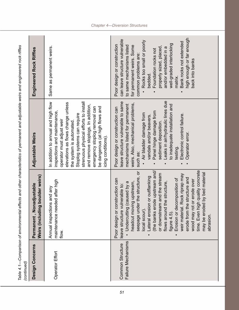
51
Chapter 4—Diversion Structures
Des
ign
Con
cern
s
Ope
rato
r Effo
rt
Com
mon
Stru
ctur
e Fa
ilure
Mec
hani
sms
Perm
anen
t , N
onad
just
able
W
eirs
(inc
ludi
ng b
ould
er w
eirs
)
Ann
ual i
nspe
ctio
ns a
nd a
ny
mai
nten
ance
nee
ded
afte
r hig
h flo
w.
Poo
r des
ign
or c
onst
ruct
ion
can
leav
e st
ruct
ure
vuln
erab
le to
:•
Und
ercu
tting
(cau
sed
by a
he
adcu
t mov
ing
upst
ream
, se
epag
e un
der t
he s
truct
ure,
or
loca
l sco
ur).
• La
tera
l ero
sion
or o
utfla
nkin
g (th
e ba
nks
erod
e up
stre
am a
nd/
or d
owns
tream
and
the
stre
am
flow
s ar
ound
the
stru
ctur
e,
figur
e 4.
5).
• E
rosi
on o
r dec
ompo
sitio
n of
w
eir m
ater
ial.
Roc
k rip
rap
may
er
ode
from
the
stru
ctur
e an
d w
ood
may
rot o
r ero
de o
ver
time.
Eve
n hi
gh q
ualit
y co
ncre
te
may
be
erod
ed b
y be
d m
ater
ial
abra
sion
.
Adj
usta
ble
Wei
rs
In a
dditi
on to
ann
ual a
nd h
igh
flow
in
spec
tions
and
mai
nten
ance
, op
erat
or m
ust a
djus
t wei
r el
evat
ions
as
flow
s ch
ange
unl
ess
the
syst
em is
aut
omat
ed.
Sto
plog
sys
tem
s ca
n re
quire
st
renu
ous
phys
ical
effo
rts to
inst
all
and
rem
ove
stop
logs
. In
addi
tion,
em
erge
ncy
stop
log
rem
oval
can
be
dan
gero
us (a
t hig
h flo
ws
and
icin
g co
nditi
ons)
.
Poo
r des
ign
or c
onst
ruct
ion
can
leav
e st
ruct
ure
vuln
erab
le to
sam
e m
echa
nism
s lis
ted
for p
erm
anen
t w
eirs
. Als
o, m
echa
nica
l pro
blem
s,
such
as:
• A
ir bl
adde
r dam
age
from
va
ndal
s an
d/or
bea
vers
.•
Pan
el h
inge
dam
age
from
se
dim
ent d
epos
ition
.•
Leak
s in
air/
hydr
aulic
line
s du
e to
inad
equa
te in
stal
latio
n an
d te
stin
g.•
Ele
ctro
nic
cont
rol f
ailu
re.
• O
pera
tor e
rror
.
Engi
neer
ed R
ock
Riffl
es
Sam
e as
per
man
ent w
eirs
.
Poo
r des
ign
or c
onst
ruct
ion
can
leav
e st
ruct
ure
vuln
erab
le
to s
ame
mec
hani
sms
liste
d fo
r per
man
ent w
eirs
. Som
e co
mm
on p
robl
ems
are:
• R
ocks
too
smal
l or p
oorly
be
dded
.•
Foun
datio
n ro
cks
not
prop
erly
siz
ed, p
lace
d,
and/
or e
mbe
dded
in a
w
ell-g
rade
d in
terlo
ckin
g m
atrix
. •
Ban
k ro
cks
not e
xten
ded
high
eno
ugh
or fa
r eno
ugh
back
into
ban
ks
Tabl
e 4.
1—C
ompa
rison
of e
nviro
nmen
tal e
ffect
s an
d ot
her c
hara
cter
istic
s of
per
man
ent a
nd a
djus
tabl
e w
eirs
and
eng
inee
red
rock
riffl
es
(con
tinue
d)

52
Planning and Layout of Small-Stream Diversions
In streams that transport large amounts of sediment, such as many channels in the desert Southwest, sediment accumulation can rapidly make weirs nonfunctional by filling the pool upstream. Sediment sluice gates can be built into the structure to deal with this problem (figure 4.4). Sudden releases of sediment through the structure during low flow can harm downstream aquatic habitat by burying gravels and macroinvertebrates.
Full-span weirs obstruct upstream passage for nonjumping aquatic organisms until and unless the crest (or floor slab in the case of adjustable weirs) is submerged in high flows so that water no longer plunges over it. Even then, many weirs remain upstream passage barriers due to high velocities and turbulence. Downstream movement, which is often passive, is impeded when fish and other organisms are entrained in diversion ditches or when they fall over the crest of a structure to land on a hard apron below (figure 4.1). To reduce the effects on aquatic species, check structures themselves can often be designed to be passable or fish ladders can be constructed around them. Fish screens can be placed on ditches. Refer to chapter 5: Fish Protection at Diversions.

53
Chapter 4—Diversion Structures
Figu
re 4
.4—
Nat
ural
Res
ourc
es C
onse
rvat
ion
Ser
vice
des
ign
draw
ing
for t
he S
an F
ranc
isco
de
Pau
da d
iver
sion
dam
, Tao
s S
oil a
nd W
ater
C
onse
rvat
ion
Dis
trict
, 200
5. T
his
dive
rsio
n si
te h
ad c
hron
ic p
robl
ems
with
sed
imen
t filli
ng in
beh
ind
the
dam
so
that
wat
er c
ould
not
be
dive
rted.
To
fix th
at p
robl
em, t
he s
luic
e pi
pe is
set
1-fo
ot lo
wer
in e
leva
tion
than
the
ditc
h in
take
, to
slui
ce s
edim
ent f
rom
abo
ve to
bel
ow th
e da
m.

54
Planning and Layout of Small-Stream Diversions
Common structure failure mechanisms are listed in table 4.1. Good structure selection and design can prevent many of these problems. For example, many adjustable weir failures are caused by mechanical problems, often due to lack of maintenance or operator error. These failures can be avoided or limited by selecting and designing a system that conforms to the operator’s ability and willingness to maintain it. In addition, using products from proven manufacturers helps avoid these problems.
Many structure failures are caused by interactions between the structure and the channel (figure 4.5). Understanding channel processes and designing for them can help avoid many problems. For example, a good design will specify floodwater elevations and flow paths to ensure that overbank floodwaters will safely flow around the structure and drop back into the channel in designated areas. Downstream activities, such as gravel mining, channel straightening or diking, can cause headcutting that may affect structures as a nickpoint moves upstream. Protecting the banks and the channel with riprap, vegetation, and other measures helps to prevent or treat these problems.
Figure 4.5—Nonadjustable log weir on Fourth of July Creek, Sawtooth National Recreation Area. This watershed burned after the diversion structures were installed. Note that high flows have already begun to outflank the structure.
55
Chapter 4—Diversion Structures
Properly designed weirs typically do not experience structural failures, such as overturning or sliding. Proper design includes keying the structure into the bed with deep cutoff walls to prevent undermining or overturning. Massive slabs are used where needed to prevent sliding. All weirs need to be keyed into the bank, and most require bank hardening (riprap, wingwalls) to avoid outflanking.
All weirs are subject to a variety of hazards, such as beaver activity, vandalism, ice, and channel erosion and outflanking during high flows. Like all instream structures, they require inspection and maintenance periodically to check for and remove debris accumulations that otherwise would reduce functioning and/or stability. Routine monitoring and maintenance also ensure that the structure does not fail due to material decomposition or erosion.
4.1.1 Types of check structures Following is a gallery of weir types, with some explanation about their utility and problems. See table 4.2 at the end of this chapter, which gives some of the flow and other environmental variables that control their applicability.
Permanent weirs: Rock weirs. Rock riffles. Rock vanes or barbs (partial span). Log weirs. Concrete/steel weirs.
Adjustable weirs: Stoplog weirs. Air-bladder weirs. Adjustable weir gates. Push-up dams, nonengineered dams.
Streambed intake structures (not a check structure)
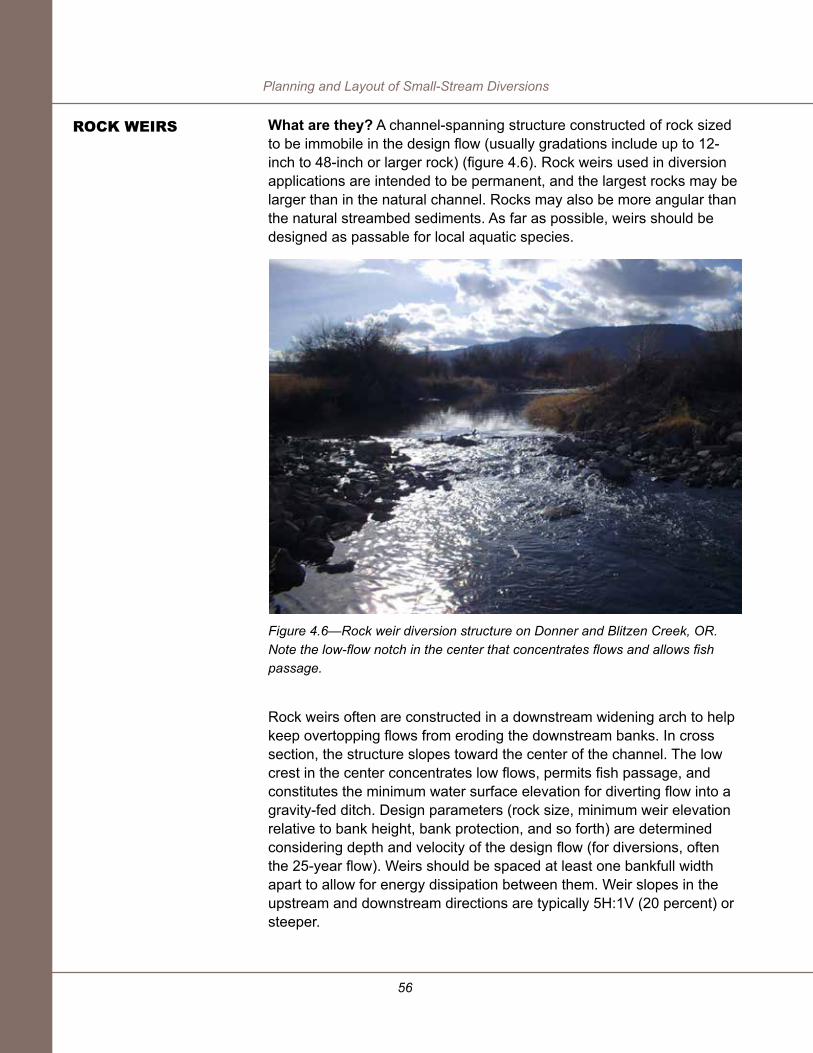
56
Planning and Layout of Small-Stream Diversions
What are they? A channel-spanning structure constructed of rock sized to be immobile in the design flow (usually gradations include up to 12-inch to 48-inch or larger rock) (figure 4.6). Rock weirs used in diversion applications are intended to be permanent, and the largest rocks may be larger than in the natural channel. Rocks may also be more angular than the natural streambed sediments. As far as possible, weirs should be designed as passable for local aquatic species.
Figure 4.6—Rock weir diversion structure on Donner and Blitzen Creek, OR. Note the low-flow notch in the center that concentrates flows and allows fish passage.
Rock weirs often are constructed in a downstream widening arch to help keep overtopping flows from eroding the downstream banks. In cross section, the structure slopes toward the center of the channel. The low crest in the center concentrates low flows, permits fish passage, and constitutes the minimum water surface elevation for diverting flow into a gravity-fed ditch. Design parameters (rock size, minimum weir elevation relative to bank height, bank protection, and so forth) are determined considering depth and velocity of the design flow (for diversions, often the 25-year flow). Weirs should be spaced at least one bankfull width apart to allow for energy dissipation between them. Weir slopes in the upstream and downstream directions are typically 5H:1V (20 percent) or steeper.
rOCK Weirs

57
Chapter 4—Diversion Structures
Rock weirs also can be designed to mimic natural boulder steps (figure 4.7a) or as cross vanes (figure 4.7b). Detailed design information for rock weirs and cross vanes is available from the NRCS (2001), NRCS (2008), California Department of Fish and Game (2008), and Rosgen (2001), among others.
Figure 4.7—(A) Constructed rock steps raise the water surface to headgate elevation at Three Forks Ranch on the Little Snake River, ID. (B) Cross-vane diversion structure, Wigwam Fishing Club, South Fork Platte River, CO.
B
A

58
Planning and Layout of Small-Stream Diversions
Where are they generally used? Step-pool and pool-riffle channels. The stream should be moderately well confined—enough that adding weirs does not increase overbank flood frequency beyond a tolerable point. Sites with at least moderate bank stability are ideal; noncohesive (sandy, silty) soils require a filter between the weir rocks and the much finer soil to avoid piping and bank erosion. Generally, the filter is a layer of gravel or geotextile filter fabric.
Considerations. Some rock weirs are nonporous, but most are porous, raising the minimum water surface elevation while allowing some flow between the rocks. One of the risks associated with porous rock weirs is that because of the leakage, minimum water surface elevation may be lower than intended, so that less water flows into the diversion ditch. Another risk is that water flowing around or under the structure may cause piping or erosion of the soils in which the weir rocks are embedded. If severe, this process can lead to structural instability and failure, which can cause fish passage, sedimentation, and water delivery problems.
Pros
Rock structures are more likely to permit aquatic species passage than smoother concrete or metal structures because the rougher rock surface may provide some slower flow pathways near the banks or between rocks. The height of a rock weir can be limited to the jump height achievable by a target fish. In steeper channels, one or a series of rock weirs can be designed to mimic the structure and height of rock steps in the natural channel so that aquatic species are likely able to move upstream through them.
Water leaking through the rocks may permit smaller organisms to swim or crawl between rocks.
Bank vegetation can grow in and between the rocks, and help stabilize the structure. It may also help to moderate water temperature.
Inexpensive if rock is locally available.
Cons
Nonadjustable: Like any structure that raises streambed elevation permanently, may cause streamflow to overtop the banks at lower flows (i.e., more frequently) than normal. Consequences might include increased bank erosion, flooding the diversion works, eroding the ditch
Water leaking between the rocks can reduce efficiency of the diversion and the amount of water available for any fish screen and bypass. This problem can be managed by sealing the structure and maintaining it regularly (see Installation). Leakage also can deter larger fish from swimming upstream if water depth over the weir crest is low.
Rocks may shift during high flows, requiring maintenance.
Structure pools water upstream, which can increase its temperature. This disadvantage is true to varying degrees for all structures that impound water.

59
Chapter 4—Diversion Structures
Installation. Installation cost depends on the availability of rock and ease of access to the site. Sealing leaks between the rocks can be challenging; plastic membranes, geotextiles, and mixtures of smaller gravel and fines are used. Sealing leaks can be important for routing enough flow to the diversion, especially if water is being provided for a fish screen/bypass system. Rock weirs can be constructed by hand and with winches if materials are onsite or can be hauled in with all-terrain vehicles (ATVs).
Streambank and streambed erosion risks can be reduced by keying rock weirs deeply into the bed and banks. Bank keys should extend well into the banks and to an elevation above bankfull to avoid outflanking. Also, footer rocks must be sized properly and placed deep enough to prevent weir-crest rocks from rolling into downstream scour holes.
Operation and Maintenance. Annual inspections are needed to ensure continued structure stability and to avoid bank erosion and other problems due to occasional rock shifting or rolling during high flows or ice events. Replacing boulders that have moved, sealing leaks that have opened, and/or removing accumulated debris may all require heavy equipment.
What are they? A permanent channel-spanning structure constructed of rock that is sized to be immobile in the design flow (usually 12-inch to 48-inch or larger rock). The rock is placed as a sloping blanket along the length and width of the streambed downstream of the point of diversion, with the goal of raising the water surface elevation at the point of diversion (figure 4.8). A series of engineered riffles is often needed to raise the water surface sufficiently.
Engineered riffles are not identical to natural riffles; rock sizes are larger for stability, pathways for organism passage may be less diverse or different in character, and turbulence may be higher. The crest may include larger rocks than average, to ensure it retains its elevation and the riffle does not move. Slopes in the downstream direction are typically 20:1 or 5 percent. The riffle cross section has a low point (thalweg) to concentrate low flows for fish passage, and rock should extend up the bank to at least bankfull elevation. Engineered riffles are sometimes placed in channels without natural riffles. Aquatic species passage should not be taken for granted.
eNGiNeereD rOCK riFFLes

60
Planning and Layout of Small-Stream Diversions
Figure 4.8—(A) Constructed rock riffles on Upper Rock Creek, Bear Lake watershed, WY. (B) Rock ramp—essentially the same as a rock riffle—constructed in 2007 on the Salmon River, ID.
B
A

61
Chapter 4—Diversion Structures
Where are they generally used? Pool-riffle streams where water surface elevation does not have to be raised very much to force water into the diversion. Ideally, the riffle fits into the stream’s pool-riffle spacing; that is, it might simply raise and stabilize an existing riffle. A rock riffle might be considered a desirable control structure in channels with low banks and channel slopes up to about 4 percent. See USDA, NRCS 2007b for an example design.
Installation. Like all rock check structures, installation cost depends on the availability of rock and ease of access to the site. Sealing leaks between the rocks can be challenging; plastic membranes and geotextiles have been used, but with time they tend to become exposed and break down. Most installations now use only well-sorted mixtures of smaller gravel and fines. Sealing leaks can be important for routing enough flow to the diversion, especially if water is being provided for a fish screen/bypass system. Rock riffles can be constructed by hand and with winches if rock is onsite or rock can be hauled in with ATVs.
Pros
Depending on the degree of similarity to natural streambed structures in the channel, may pass a variety of endemic aquatic organisms. Like rock weirs, engineered riffles can be designed (using hydraulic methods) to pass a target fish within a certain flow range.
Inexpensive if rock is available locally and the site has good access for equipment. With your own equipment, a rock riffle on a small stream can be built in a couple of hours. Strict precision with elevations is not necessary.
Bank vegetation can grow in the rocks, and help stabilize the structure. It may also help to moderate water temperature.
Water leaking through the rocks may permit smaller organisms to swim or crawl between rocks.
Cons
Nonadjustable: Like any structure that raises streambed elevation permanently, may cause streamflow to overtop the banks at lower flows (i.e. more frequently) than normal. Consequences might include increased bank erosion, flooding the diversion works, eroding the ditch.
Water leaking between the rocks can reduce efficiency of the diversion and the amount of water available for any fish screen and bypass. This problem can be managed by sealing the structure and maintaining it regularly (see Installation below). Leakage also can deter larger fish from swimming upstream if water depth over the crest is low.

62
Planning and Layout of Small-Stream Diversions
Streambank erosion risks can be reduced by keying rock deeply into gravelly, sandy, or silty banks. Bank keys in these materials should extend well into the banks and to an elevation above bankfull to avoid outflanking. In tough clayey soils that resist erosion, avoid disturbing the soil, and protect the banks with rock placed like riprap. Ensure the center of the riffle is low to provide a low-flow thalweg for aquatic organism passage.
Streambed erosion—a potential risk at rock weirs—is also a risk at riffles even though water does not plunge over the structure. Both types of structures must be constructed to effectively dissipate energy and limit downstream scour.
Operation and Maintenance. Annual inspections are needed to ensure continued structure stability and avoid bank erosion and other problems due to occasional rock shifting or rolling during high flows or ice events. Replacing rocks that have moved, sealing persistent leaks, and/or removing accumulated debris may all require heavy equipment. More frequent debris removal from the top of the riffle may be necessary at sites where a lot of water is being diverted and the stream is moving debris.
What are they? These rock structures span only part of the channel cross section. When used as diversion checks, they raise the water surface in the vicinity of the bank where the diversion is located, and permit free flow and aquatic species passage across the rest of the channel (figure 4.9). They are usually constructed pointing upstream at an angle from the bank (USDA, NRCS 2007a) and sloping down from the bank. This helps keep water overflowing the barb away from the downstream near-bank area, avoiding bank scour. Like other rock structures, the rock is sized to be immobile in the design flow (usually 12-inch to 48-inch or larger rock).
On streams with mild slopes less than 1 percent, vanes generally should block no more than one-fourth to one-third of the bankfull channel width. On steeper streams, a barb generally needs to extend across the thalweg to influence water surface elevation enough that water flows into the diversion. Such a structure may block low flow entirely, in which case it is functioning as a weir, or it may simply raise minimum water surface elevation while allowing some flow between the rocks or around the end of the structure.
rOCK BArBs/VANes

63
Chapter 4—Diversion Structures
Figure 4.9—Rock barbs bracket a diversion channel on the Uncompahgre River, south of Montrose, UT. The barbs were placed to protect the headgate (not pictured).
Where are they generally used? Barbs are used where the amount of water diverted is small compared with instream flow, and a relatively small increase in water surface elevation in the bank vicinity is needed to supply the ditch. This means they are most useful on mildly sloping streams (<~0.5 percent) with relatively high irrigation season flows. They are not useful where a diversion takes all or most of the flow. They are best used on wider streams where the vane will not deflect water into the opposite bank at moderate to high flows.

64
Planning and Layout of Small-Stream Diversions
Installation. Like all rock structures, installation cost depends on the availability of rock and ease of access to the site. Sealing leaks between the rocks can be challenging; plastic membranes, geotextiles, and mixtures of smaller gravel and fines are used. Sealing leaks can be important for routing enough flow to the diversion, especially if water is being provided for a fish screen/bypass system. Cross vanes can be constructed by hand and with winches if materials are onsite or rock can be hauled in with ATVs.
Operation and Maintenance. Annual inspections are needed to ensure continued structure stability and avoid bank erosion and other problems due to occasional rock shifting or rolling during high flows or ice events. Replacing boulders that have moved, sealing leaks that have opened, and/or removing accumulated debris may all require heavy equipment.
Pros
Does not block entire channel cross section, and provides free upstream aquatic organism passage as well as downstream sediment and debris movement.
Bank vegetation can grow in the rocks, and help stabilize the structure. Angled construction helps avoid bank erosion downstream.
Cons
Nonadjustable: Like any structure that raises streambed elevation permanently, may cause streamflow to overtop the banks at lower flows than normal. This is less likely than for rock weirs and riffles because the structure spans only part of the channel.
Like other rock structures, must be keyed into the bed and banks for stability. Keying rocks in to bankfull elevation requires substantial bank disturbance.

65
Chapter 4—Diversion Structures
What are they? One or more logs or timbers spanning the entire stream, and long enough to pass bankfull flow (at a minimum) between the banks. Logs may be pinned together, or cabled or chained to ballast—a large, heavy object buried in the streambed or bank that acts as an anchor keeping the logs from floating away. Like rock and concrete weirs, log weirs should have a low-flow notch or slope toward the middle of the channel. Constructing them in a V-shape in cross section and plan view (V pointing upstream) forces water to converge in the channel center, and reduces the tendency to accumulate sediment and become vulnerable to outflanking. This also reduces the tendency for water to eddy around the downstream banks, which could erode them and lead to outflanking. Log weirs should be keyed deeply into bed and banks to avoid outflanking and undercutting. Typically, two logs are stacked to help avoid undercutting as water plunges over the weir crest (figure 4.10).
To facilitate upstream fish passage, construct log (like rock) weirs in steps no higher than local fish can jump. Permanent weirs should generally not be used where local fish species do not jump, because they prevent upstream movement until high flows submerge the drop. Possible turbulence below the drop may also affect fish passage. Crawling aquatic species have to travel around or over the entire weir.
Figure 4.10—Two log weirs installed as diversion checks on Fourth of July Creek, Sawtooth National Recreation Area, ID. This is the same installation pictured in figure 4.5.
PerMANeNT LOG Weirs

66
Planning and Layout of Small-Stream Diversions
Installing no fewer than three log weirs in series is advisable to prevent scour from undermining the weir or increasing the drop height. The reason is that setting weirs precisely to the intended elevation is difficult, and some scour can be expected. Scour holes can be especially deep in fine-grained materials. To stabilize grade through the diversion reach and ensure that each upstream weir is backwatered by the weir downstream, set the weir furthest downstream at current streambed elevation. It is less expensive to put in several weirs initially than to go back after some downcutting has occurred and add additional controls.
Where are they generally used? Availability and portability generally influence the choice of logs or timbers for a diversion dam. A permanent log weir might be the structure of choice in a remote area where logs are easily available from adjacent uplands. For small streams without road access, small logs can be hauled in cost effectively using ATVs.
Log weirs require banks that are more stable than those where a rock or concrete structure might be placed (see table 4.2). Whereas rock can adjust (individual rocks roll or shift) when the streambed or bank erodes slightly, logs cannot. Also, they are not impermeable like concrete or steel, and water flowing between the individual logs or timbers can cause piping in poorly consolidated fine-grained soils, possibly undermining the structure. Filter fabric can be used to help limit piping, but if the fabric tears, soil can erode through the holes.

67
Chapter 4—Diversion Structures
Pros
Logs are often available nearby in forested areas. Small logs and other construction materials are light enough to move using ATVs.
Usually inexpensive.
Cons
Nonadjustable: Like any structure that raises streambed elevation permanently, may cause streamflow to overtop the banks at lower flows than normal.
Banks must be high enough to support bank keys, and logs must be keyed deeply into the banks for stability. Streambed excavation is required to bury ballast.
Porous. Leaks are a challenge to seal.
Uniform, straight logs may be hard to find.
Failure prone if not properly designed for the site and carefully constructed.
Installation. Log or timber weirs require design just like any other weir type, and they are not trivial to build. Placing the logs so that they are lower in the channel center and angled upstream is important, and requires care during construction; getting this wrong raises the risk of outflanking. Placing two or three layers of geotextile upstream of the structure (figure 4.11) is important to avoid undercutting and piping. Bank stabilization measures, such as additional stacked logs, log cribs, or rock riprap are necessary. Keying in log weirs generally requires less bank disturbance than for rock structures because logs are straight and narrow relative to most rocks. A notch into the bank the width of an excavator bucket is all that is needed to key them in well. The streambed is disturbed if ballast is buried to prevent logs from floating away, but the extent of disturbance is less than for rock or concrete weirs. Installation in flowing water is difficult since the logs float.
Operation and Maintenance. Inspections are needed after high flows to check for bank erosion, accumulated debris, or other problems that could endanger structure stability. Log weirs also should be inspected annually for bank and bed erosion, seepage and leaks, and the condition of mechanical fasteners (pins, clamps, cables, etc.). Plan for some maintenance or repair annually.
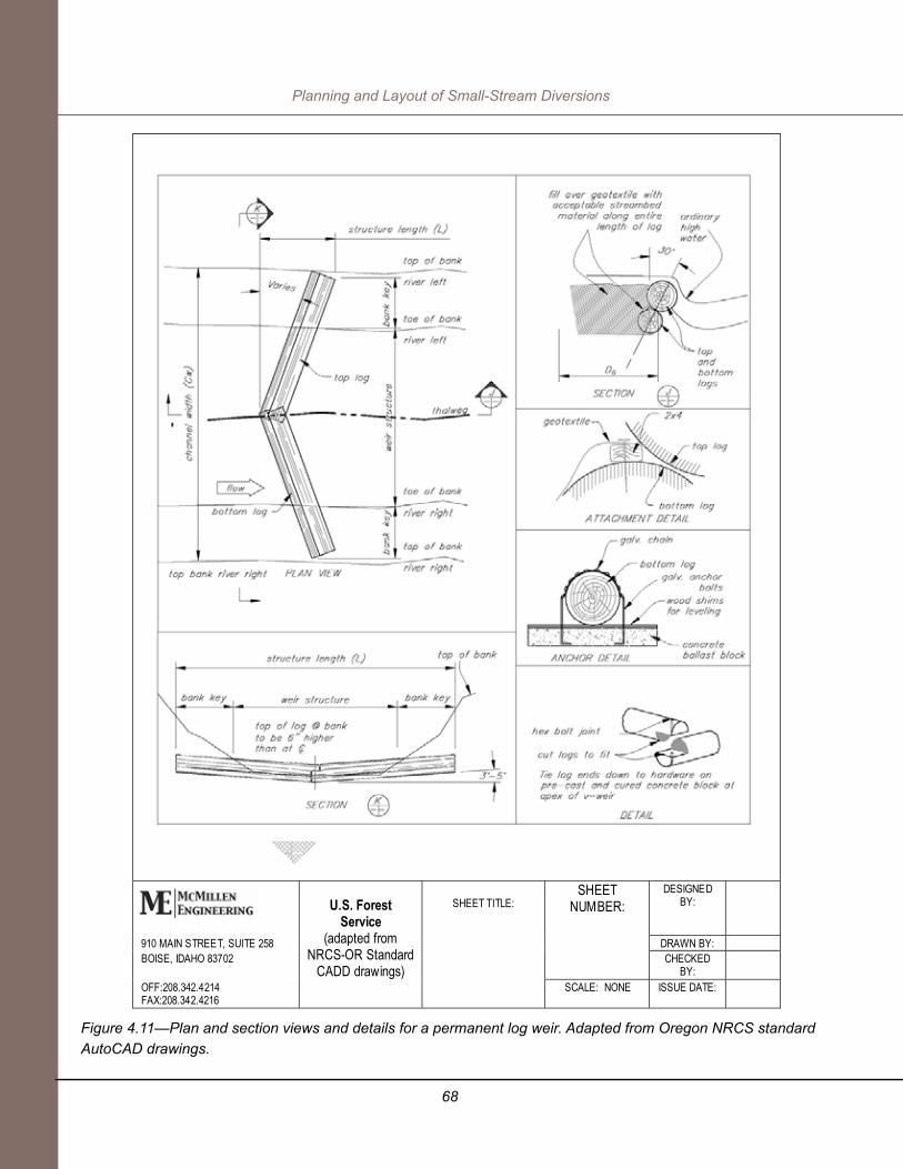
68
Planning and Layout of Small-Stream Diversions
Figure 4.11—Plan and section views and details for a permanent log weir. Adapted from Oregon NRCS standard AutoCAD drawings.
DESIGNED BY:
910 MAIN STREET, SUITE 258 DRAWN BY: BOISE, IDAHO 83702
SHEET NUMBER:
CHECKED BY:
OFF:208.342.4214 FAX:208.342.4216
U.S. Forest Service
(adapted from NRCS-OR Standard
CADD drawings)
SHEET TITLE:
SCALE: NONE ISSUE DATE:

69
Chapter 4—Diversion Structures
What are they? Concrete and steel weirs are permanent channel-spanning structures of concrete wall or steel piles or panels. These are the strongest, most durable, and least porous check structures. Unless there is a separate fishway, the entire streamflow passes over the crest, so the weir should have a low-flow notch and other design features to concentrate low flows and provide for upstream fish passage.
Smooth concrete walls or steel panels accelerate flow velocity and increase downstream scour potential. The streambed and banks downstream must be protected from high velocity flows by concrete aprons, riprap, and/or energy dissipaters, such as boulder clusters on the bed. On banks, riprap and vegetative interplantings are generally used for erosion control. Note that in figure 4.12, the weir steps are V-ed upstream to help direct the flow and avoid bank erosion.
Figure 4.12—Steel weir, Ochoco Creek, Crook County, OR. Note the low-flow notches in the center designed to concentrate flows and allow fish passage. The structure has multiple low steps to facilitate juvenile fish passage and dissipate energy.
Where are they generally used? Concrete structures are solid and uniform compared to log or rock structures, so they can be designed strong enough to raise water level higher than either log or rock structures can. They are used commonly on larger streams, or where a diverter has the right to take most or all of the remaining water in the stream. In this case, concrete or steel may be preferable from the standpoint of upstream fish passage, because seepage through more porous materials like rock or logs would reduce the amount of flow available for an upstream passage facility and fish screen.
CONCreTe Or sTeeL Weirs

70
Planning and Layout of Small-Stream Diversions
Concrete and steel may be more desirable where soils are porous and/or highly erodible, and where durability is important. Design methods and material properties are well defined for these human-made materials, and the structure’s final properties are predictable and reliable. They can be constructed with cutoff walls and massive aprons to reliably avoid sliding, overturning, and undermining.
Installation. These structures tend to be more costly than other options, both because of materials costs and mitigating the risks to the stream channel and aquatic organisms. Construction requires dewatering the worksite, which can be challenging. Large structures require good access for concrete mixing trucks. Concrete, steel, or aluminum for very small structures (streams narrower than about 10 feet) could be brought in on ATVs and the concrete could be mixed onsite.
Operation and maintenance. These weirs generally require no more than periodic checks for debris accumulation and damage from debris battering, bank erosion, or downstream scour. As long as repairs are made in a timely way, the structures are highly reliable.
Pros
Strong, solid structures with predictable material properties. They may be a good choice in erodible soil materials.
Not as porous as rock or log weirs, so at very low flows, more water is available for fish passage. Very low flows can be concentrated through a notch.
Durable with regular maintenance.
Cons
Nonadjustable; stream may change location or elevation, and structure doesn’t conform.
If fish passage is not designed into the structure, fish moving upstream when water plunges over the crest will either have to jump or a fish ladder will have to be provided. Aprons impede fish jumping, and fish moving downstream may be hurt when they fall onto a solid apron.

71
Chapter 4—Diversion Structures
What are they? Short stoplogs (2-foot to 12-foot boards or tubes) are placed in slots or stanchions attached to the floor of the weir (figures 4-13 and 4-2). Installation and removal of the stoplogs adjusts the water surface elevation. Incremental change is generally 2 to 6 inches.
Figure 4.13—Stoplog diversion dam on Elk Creek, Sawtooth National Recreation Area, ID. (A) The dam had a central notch for upstream-migrating adult salmonid spawners, but passage for adults was not assured and passage for juveniles was believed to be nonexistent (Moulton 2010). The diversion is in back and to the right of the dam, unseen in this photo. (B) To improve fish passage and habitat, the dam was removed in 2009 and replaced by a well.
ADJUsTABLe sTOPLOG Weirs
B
A

72
Planning and Layout of Small-Stream Diversions
Where are they generally used? Adjustable dams are used where it is not possible or desirable to construct a permanent bed-elevation control high enough to divert water throughout the diversion season. Adjustable dams allow raising the minimum water surface elevation as flows decrease over the summer to continue delivering water to the diversion. Stoplog dams can be manipulated by hand, so they are used in remote locations without power or automation. Their low cost also makes them attractive: they can be constructed of readily available—sometimes even surplus—materials. However, it can be quite dangerous to manipulate the boards during high flows when water pressure holds them in place, and often stoplogs are not removed in a timely way.
Installation. The structure is comprised of bed and bank keys, floor slab and walls of concrete or wood, stoplog slots or stanchions, and the stoplogs. Construction generally requires dewatering and bed and bank excavation. For small installations, materials may be portable using ATVs.
Pros
Water surface elevation does not have to be permanently raised, and flow during much of the year can be nearer normal than is possible with nonadjustable weirs. See also table 4.2.
These are common, easily understandable structures. It is relatively easy for landowners to understand and approve of modifications, such as leaving out one or two boards for fish passage.
Can be constructed with readily available—sometimes leftover materials—making them inexpensive.
Cons
Due to the difficulty of removing saturated boards with water pressure against them, boards are sometimes not removed in the fall. The resulting overflow can cause scour and sediment deposition during the next flood event, creating an additional maintenance need.
Notches may not provide adequate passage for fish or other aquatic species.
When dam boards are finally removed, a concentrated wave of sediment may be released to settle out on the streambed somewhere downstream.

73
Chapter 4—Diversion Structures
Operation and maintenance. Dam boards should be adjusted weekly or more frequently when flow is fluctuating. The site must be accessible enough for the operator to make adjustments to the weir when floods occur. The operator also must be committed to vigilance and timely response during a runoff event that could cause damage to the structure, channel, or ditch. Failure to remove dam boards before high flows can lead to problems with downstream bed scour, bank erosion, fish passage, sediment accumulation behind the dam, and ditch breaching and consequent gullying (figures 1.8 and 3.1).
Inspections are needed after high flows to check for bank erosion, accumulated debris, or other problems that could endanger structure stability. Weirs also should be inspected annually for bank and bed erosion, seepage and leaks, and the overall structure condition. Plan for some maintenance or repair annually.
What are they? Rubber air bladders are placed on concrete or wood floor slabs, and are protected by hinged steel panels that cover the air bladder at all flows (figures 4.14 and 4.15). The air bladder is inflated using an air compressor, raising the steel panels that control water surface elevation. Elevation adjustments can be made in fractions of an inch. At large diversions, these systems can be automated to adjust dam height as flow in the main river changes. This allows the structure to maintain constant flow in the diversion.
Figure 4.14—Air-bladder diversion dam on Ochoco Creek, OR. A fish ladder is located to the left of the photo. The structure is reinforced at the ends with rock riprap to limit erosion around the concrete wingwalls. Longer wingwalls than shown
here would help avoid seepage and outflanking. A concrete apron prevents bed scour at the overfall, and could affect downstream-migrating aquatic organisms.
Air-BLADDer Weirs

74
Planning and Layout of Small-Stream Diversions
Figu
re 4
.15—
Sch
emat
ic d
raw
ing
of a
djus
tabl
e ai
r-bla
dder
wei
r.

75
Chapter 4—Diversion Structures
Adjustable dams are used where it is not possible or desirable to construct a permanent bed-elevation control high enough to divert water throughout the diversion season. Adjustable dams allow you to raise the water surface elevation as flows decrease over the summer to continue delivering water to the diversion. Air bladders can be inflated mechanically directly by the operator onsite or remotely, or they can be adjusted automatically. The inflation system requires electrical power at the site.
Fine sediment can plug the weir’s hinges so that the panel has difficulty opening. Air-bladder weirs are less sensitive to this problem than other adjustable or tilting weirs because the bladder exerts pressure over the whole panel area, resulting in large forces that can overcome some sand embedded in the hinge. Nonetheless, air-bladder weirs would not be the first choice of structure type in channels that transport large amounts of sand and silt-size sediment.
Pros
Water surface elevation does not have to be permanently raised, and flow during much of the year can be nearer normal than is possible with nonadjustable weirs.
Less dangerous than hand-placed stoplogs and more likely to adjust in a timely way, because no manual manipulation is needed.
Compared to stoplog weirs, more likely to seal tightly, allowing more water to be sent through a constructed fish ladder and/or a fish screen/bypass system.
Cons
Grid electricity or a generator and engine are required onsite to run the air compressor. Solar panels do not generate enough power. Power is not required all the time—only when water surface elevation needs to be changed.
Upstream fish passage requires an off-stream facility: a fishway, such as a ladder or a side channel.
If construction is not done well, experience shows that pipes running to the bladder develop small leaks, creating the need to run the air compressor frequently.
See also table 4.1, which lists advantages and disadvantages of adjustable versus permanent diversion structures.

76
Planning and Layout of Small-Stream Diversions
In areas with active beaver colonies, air bladders are at risk of being chewed. Both beavers and human vandals have caused failures by puncturing air bladders. A way of reducing their susceptibility to punctures is to have ceramic chips or rods mixed in with the rubber material during fabrication.
Installation. The structure is comprised of bed and bank keys, floor slab and walls of (usually) concrete, an air bladder, air compressor, and a steel panel. Construction generally requires dewatering and bed and bank excavation. Precision construction is required to create a level surface and allow for sealing the bladder tightly to the walls and floor. The plumbing serving the bladder should be installed carefully and sealed to avoid leaks developing later.
Operation and maintenance. The operator must conduct startup and ongoing maintenance of the air compressor. If the air compressor is operating frequently even when the water level is not changing, check for leaks in the airlines to the bladder. The weir plate also should be checked annually for sediment accumulation at the hinge, and cleaned if necessary. Check the bladder for small punctures.
Inspections are needed after high flows to check for bank erosion, accumulated debris, or other problems that could endanger structure stability. Weirs also should be inspected annually for bank and bed erosion, seepage around the outside walls, and overall structure condition. Plan for some maintenance or repair annually.
What are they? This category includes several types of adjustable weirs that are seen rarely on national forests, but might occasionally be encountered, especially at large diversions. In general, these weirs mostly have been replaced by air bladder weirs, which are easier to manipulate and more reliable.
One type of adjustable weir gate slides up and down between vertical walls on either side of the channel. It might be on tracks, or simply set against concrete walls. Hydraulic or air cylinders, lead screws, or winches might move the gate.
Tilting weirs (figure 4.16) have a panel that is hinged or attached to a tube that rotates. The hinge or tube is attached to the floor of the structure. The panel is raised or lowered by means of a cable winch or torque tube to change the water surface elevation.
ADJUsTABLe Weir GATes

77
Chapter 4—Diversion Structures
Figu
re 4
.16—
Sch
emat
ic d
raw
ing
of ti
lting
wei
r with
con
cret
e si
ll an
d w
ingw
alls
.

78
Planning and Layout of Small-Stream Diversions
Radial gates (figure 4.17) are curved plates—commonly of corrugated galvanized steel—that rotate around a hinge on the weir sidewall, and are raised by a cable winch. This type of adjustable gate is highly undesirable for fish because when closed or only slightly open, upstream-migrating fish may attempt unsuccessfully to jump the gate and they may be stranded after landing on the horizontal bars or shelves visible in the photo.
Figure 4.17—Radial gates at lower Cub River diversion, Bear Lake watershed, ID. These gates are open now, but when closed, they raise the upstream water surface elevation by about 2½ feet.
Where are they generally used? Adjustable-gate weirs that slide vertically are more appropriate for taller check structures where there is enough fall across the weir to keep it clear of sediment that would prevent the gate from closing. Because they do not take up much channel length, they are more likely to be used where the water surface elevation must be raised up high.
Tilting-weir gates are susceptible to hinge damage from fine sediment, and they require problematic synchronized lifters on both sides of the channel. They are rarely used for these reasons.
In salmonid habitats, radial gates are used rarely now because of the harm they cause to migrating adult fish.

79
Chapter 4—Diversion Structures
Installation. Because these weirs are set in concrete walls, installation issues are similar to those for concrete weirs. They are more complex because power must be supplied, and gate actuator mechanisms also must be installed unless the gate is hand manipulated.
Operation and maintenance. For vertical sliders and radial weirs, debris must be removed from the floor so that the weir can seal. All adjustable weir gates require annual startup maintenance, winch maintenance, bearing and gear lubrication, and cables checked for fraying.
Pros
Mechanically adjustable.
Like other weir styles, flow over the crest increases rapidly with increasing upstream head. Therefore, these are good for maintaining a relatively constant upstream water surface elevation and ditch flow even when instream flow increases greatly.
Radial gates are well-balanced and easy to lift. They work well with high sediment loads because the hinges are out of the water.
Radial gates can be moved easily using a hoist setup.
Cons
Poor in streams with high sediment loads because sediment resting on weir floor can prevent gate from closing. Fine sediment can bind hinges of tilting weirs.
Radial gates are quite dangerous for upstream migrating fish because they attract fish and encourage them to jump at the back of the gate.

80
Planning and Layout of Small-Stream Diversions
Pushup dams and pole-and-tarp dams are some of the most common check structures at farm diversions. Pole-and-tarp dams are hand built using whatever materials are handy to raise the water surface elevation high enough to run it into the ditch (figures 4.18 and 4.19). Pushup diversion dams are constructed by hand or heavy equipment from streambed or streamside rock and gravel. Wingdams are one example common on the Salmon River and its tributaries (figure 4.20). They are quasi-permanent nonengineered barbs that extend at an acute angle from the streambank across as much as 75 percent of the channel width.
These check structures have serious disadvantages. For example, the headgate is often some distance down the ditch, and the ditch upstream of the headgate can be overtaxed by large volumes of water, especially when the stream is running high. Fish are also diverted into the ditches supplied by these diversion structures, and fish screens and safe bypasses back to the stream are generally not provided.
Figure 4.18—Check structure using logs to support a plastic tarp on the Medicine Bow National Forest, WY. The ditch is to the left out of the photo. This check structure is not removed at the end of the season.
NONeNGiNeereD CHeCK sTrUCTUres
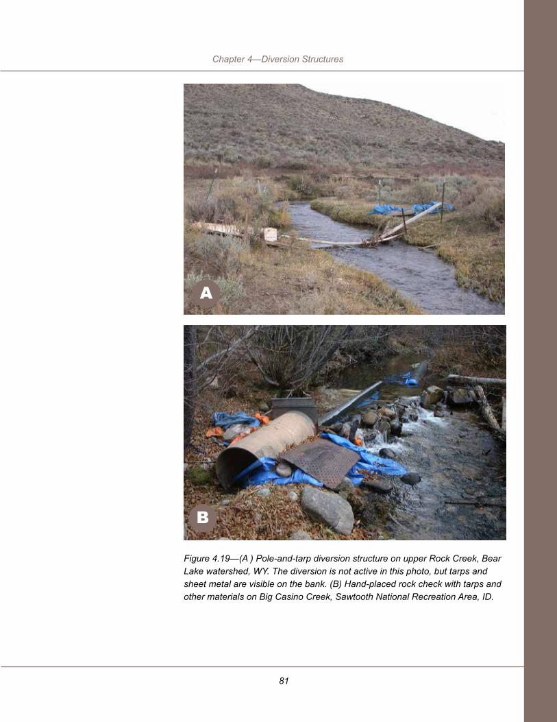
81
Chapter 4—Diversion Structures
Figure 4.19—(A ) Pole-and-tarp diversion structure on upper Rock Creek, Bear Lake watershed, WY. The diversion is not active in this photo, but tarps and sheet metal are visible on the bank. (B) Hand-placed rock check with tarps and other materials on Big Casino Creek, Sawtooth National Recreation Area, ID.
B
A

82
Planning and Layout of Small-Stream Diversions
Figure 4.20—Bulldozer-constructed wingdam with diverted water in foreground. East Fork Salmon River, ID. This diversion was replaced and combined with another diversion in a Bureau of Reclamation project aimed at reducing harm to anadromous and resident fish species in 2003. Photo courtesy of Brian Hamilton, Bureau of Reclamation, Salmon, ID.
Using a bulldozer or excavator to construct a pushup dam disrupts the streambed on at least an annual basis, and if the dam washes out in a summer storm, disturbance can be more frequent. Pushup dams often are not removed after the diversion season, but are allowed to erode during high flows. Water quality effects of dam washouts may or may not be important, depending on the system.
Pushing streambed materials around loosens the streambed and mobilizes sediment for transport. The disturbed streambed materials are more prone to erosion and the streambed may scour, creating a zone of scour that moves upstream and can require the wingdams to be extended in a continuing cycle. Direct streambed disturbance may be much less of an issue with hand-built pole-and-tarp dams.
Leakage is an operational problem with these dams. It may reduce the amount of water diverted, as well as the amount of water available to operate a fish screen and bypass fishway. Often, straw or plastic is added to pushup dams to seal them.

83
Chapter 4—Diversion Structures
Pushup dams are being replaced in many locations where water conservation, channel stability, and aquatic ecosystem functioning are management goals. Figure 4.21 shows the structure that replaced the pushup dam in figure 4.20. It is a rock weir with two drops sized to permit passage of endemic fish species.
Figure 4.21—Two diversions, including the pushup dam in figure 4.20, were consolidated into one on the East Fork Salmon River. The new diversion structure is an A-weir with two rock weir drop structures for salmonid fish passage. Photo courtesy of Brian Hamilton, Bureau of Reclamation, Salmon, ID.
What are they? An open pipe or narrow box embedded in the streambed with a downstream-sloping grating across the opening for water to enter (figure 4.22). Streambed intake structures differ from infiltration galleries in that they are open at streambed elevation, whereas pipes feeding an infiltration gallery are buried in the streambed. The structure may or may not span the entire streambed. Water runs by gravity through a valve to the distribution infrastructure—a pump sump, ditch, or pipe. The structure slopes toward the bank steeply enough to sweep any coarse sediment to a sump that can be cleaned out or to a sediment sluice gate if the amount of trapped sediment is high. Perforated-plate or wedge-wire fish screens may be secured on top of the grating to protect fish from being sucked into the diversion. Screens also help keep gravel out of the diversion.
sTreAMBeD iNTAKe sTrUCTUres

84
Planning and Layout of Small-Stream Diversions
These structures work well only where there is plenty of flow that will not be diverted. The gratings tend to take in water so fast that, in shallow water, most of the surface flow may enter the top of the opening and return back out again at the downstream side of the grating, leaving the middle section dry or nearly dry (figure 4.23). Downstream-migrating fish may be able to negotiate the narrow dry patch by flopping and rolling but when leaves and twigs are allowed to accumulate there, fish may be blocked and die. Such structures require diligent maintenance to keep them clear of debris. For these reasons, streambed intake structures are often frowned upon by regulators.
Figure 4.22—Streambed grated intake structure in Boundary Wildlife Management Area, Boundary Creek, ID, operating at low winter flow. This structure is operated by hand to maintain instream flows; no water is diverted at flows less than 50 cubic feet per second (cfs). Permissible diversion rates vary depending on flow in the main channel, and the maximum permissible rate is 20 cfs.

85
Chapter 4—Diversion Structures
Figure 4.23—Streambed water intake and fish screen on Clear Creek, near Halfway, OR. This structure is a corrugated metal pipe with rectangular holes cut in the top that are covered by a grating. The grating slopes downstream 6 inches in 2 feet (25 percent) so that flow across the top will sweep it clear of debris. This works as long as the grating is submerged, but at low flows, all streamflow may enter at the top and resurface near the bottom, creating a problem for debris and fish passage. Note the piece of culvert at the far side of the stream channel. It acts as a low dam narrowing the channel so that water flows toward the diversion structure. An opening for upstream fish passage can be seen between the two structures.
A different type of gravity intake structure—an end-of-pipe intake screen—can work in limited situations (figure 5.11), where the diversion takes only a small fraction of streamflow. This device sits on or slightly above the streambed where water is reliably deep enough, perhaps in a midstream pool or deep glide. Unlike streambed intake structures that are swept by the flow, passive end-of-pipe screens require frequent checking to remove debris. To avoid that, many end-of-pipe screens include air or water backwash cleaning systems. These screens can effectively prevent fish from entering the ditch or conveyance pipe if they are designed properly. See section 5.1.3.

86
Planning and Layout of Small-Stream Diversions
Where are they generally used? Streambed intake structures have been tried, but not used extensively in the Pacific and Inland Northwest States because of regulatory agency objections to possible ‘take’ of listed fish that could occur if the grating is not kept clear of debris. In other States, they may be useful at sites where plenty of high-velocity bypass flow is available to sweep debris from the screen and/or keep the entire structure submerged at all flows. Like all permanent diversion structures, they require engineering design and construction supervision.
Installation. Like other instream structures, streambed intakes require instream construction permits, dewatering (critical to the success of any instream concrete structure), and accurate elevation control to set structure at correct grade.
Operation and maintenance. If the structure is designed properly to handle local variability in flow and sediment loading, little operation and maintenance attention is needed. If no fish screen is installed, sediments smaller than the grating openings are likely to fall in or become wedged in the openings. If a fish screen with 3/32-inch openings is installed, sand grains stuck in the openings can generally be removed by pressure washing or by breaking the grains off with a shovel.
Pros
Do not block streamflow; do not cause water quality or channel stability problems associated with ponding or sediment and wood accumulation as upstream of a dam, or with streambed erosion downstream.
Easy to prevent fish entrainment by placing approved screen materials on top of grating.
Assuming good design and installation, requires little effort to operate and maintain.
Cons
All surface flow may enter at top of grate, leaving midsection dry. Even if most flow resurfaces at downstream end of grate, downstream-migrating fish may come in contact with the grating.
If maintenance is needed, it would be instream work, possibly requiring a permit depending on State law.

87
Chapter 4—Diversion Structures
Pumps are used to raise water to a higher elevation or pressure. They can be placed in a pool in the channel, but instream placements are vulnerable to sediment and debris accumulations. Whether they are placed inchannel or off, pumps nearly always require an intake screen to protect aquatic organisms and the pump itself. One of the principal considerations for locating pump stations is the need for electric power.
For a permanent pump station, a screen is placed at the bank toe (figure 4.24) or on the streambed (figure 4.22). Water entering the screen is conveyed by gravity to a sump located adjacent to the bank. The bottom of the sump and the pump suction should be located several feet below the low water surface elevation to access water at all design flows. Installing a permanent, screened pump station requires heavy-equipment access to the site, dewatering, and some inchannel excavation.
Figure 4.24—Bank screen protecting pump station located behind bank, Kalapuya (also spelled Calapooia) River, near Brownsville, OR.
4.2 PUMP sTATiONs
The pump suction is the end of the pipe where water is drawn into the
pump.

88
Planning and Layout of Small-Stream Diversions
Pumps and/or generators also can be located on the streambank, connected to moveable screens and pipes that are moved as flow in the source channel changes (figure 4.25). Such a pump station may have almost no permanent impact on the channel itself, and it affords great flexibility in operation. However, the operator needs to be extremely careful about keeping track of flow changes. Nonfloating equipment may need to be moved rapidly to protect it from flooding or being washed away. Likewise the pump could burn out if water level drops leaving the intake dry. This kind of pump station is appropriate on big, relatively flat rivers where there is plenty of water depth and flow is not fast or turbulent enough to make the pump and screen gyrate or swing, which could disrupt water delivery.
Figure 4.25—Streambank pump with floating screened pump suction on Bear River, UT. Photo courtesy of Warren Colyer, Trout Unlimited.
AdvantagesPumps have several advantages over other types of diversion control structures.
● Water surface elevation in the stream does not have to be raised for a pump station intake.
● Temporary or removable pump intakes may be taken out of the stream to protect from ice and debris damage.

89
Chapter 4—Diversion Structures
● Total diversion flow is not changed significantly by normal variations of instream water depth. (Therefore, diverted flow does not change much during storm-runoff periods.)
● Pump suction screens are an off-the-shelf item preapproved for use in several Northwest States.
● Pumps can be lowered to follow water as the streamflow decreases.
DisadvantagesPumps also have several disadvantages compared to other types of structures.
● Continuous power requirements (either electricity or fuel).
● Removable pump stations may be hard to reinstall at high flows (occasionally spring runoff occurs when crops require significant irrigation).
● Pumps require maintenance that the irrigator may not be qualified to perform (i.e., motor rewinding, seal replacement).
● Pumps are subject to damage from flooding.
How pump stations failTypical failure modes include:
● Mechanical Failure
■ Bearing and shaft wear due to abrasive sediment load (sand).
■ Impeller wear (sand).
■ A hole in the screen can allow debris into the pump causing impeller damage.
■ Screen can plug and the pump can burn out.
■ Pump is damaged by cavitation (because pump is placed too far above the water surface).
● Stream Mechanics/Site Design Errors
■ Sump fills with sediment.
■ Pump suction location is damaged by streambank erosion.
■ Pump is flooded at high water or pump suction is high and dry at low water.

90
Planning and Layout of Small-Stream Diversions
In mountain rivers transporting sand and silt, pumps frequently fail when the pool they are placed in fills with sediment, and the sand wears out the pump bearings and impeller. Beware of constructing a weir or crossvane in such a stream with the idea of creating a deep enough hole for a pump. Sediment deposition is likely to create problems there.
These failures can be avoided or treated by designing systems tailored to site conditions. For example, designers should select a pump and screen that can tolerate sand if the stream transports large amounts of sand. The screen should be durable, and it should be protected by a trash rack or other protective structure if the screen might otherwise be subject to damage from debris. The pump location should be protected from erosion and flooding. Using pump and screen designs from proven manufacturers and vendors will help in avoiding some of these problems. Also, designers should try to assure that the pump installation will not require more diligent inspection and maintenance than the operator is able and willing to supply.
Figure 4.26 shows how stream adjustment can sabotage a pump installation. A log-crib diversion dam, a remnant of which can be seen in the foreground, was removed to facilitate fish passage on the Kalapuya River in Oregon. A pump station replaced the dam; its screen is visible on the left in the process of being cleaned by waterburst. Dam removal planners had predicted the main thread of flow in the restored channel would be at the outside of this gentle bend, near the screen. However, the thalweg is currently located away from the screen, and the screen may not receive flow at the driest time of the year.
Figure 4.26—Kalapuya River pump station and river context. See text for explanation.
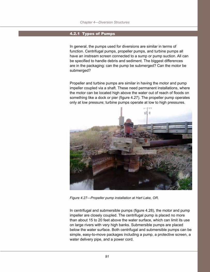
91
Chapter 4—Diversion Structures
4.2.1 Types of Pumps
In general, the pumps used for diversions are similar in terms of function. Centrifugal pumps, propeller pumps, and turbine pumps all have an instream screen connected to a sump or pump suction. All can be specified to handle debris and sediment. The biggest differences are in the packaging: can the pump be submerged? Can the motor be submerged?
Propeller and turbine pumps are similar in having the motor and pump impeller coupled via a shaft. These need permanent installations, where the motor can be located high above the water out of reach of floods on something like a dock or pier (figure 4.27). The propeller pump operates only at low pressure; turbine pumps operate at low to high pressures.
Figure 4.27—Propeller pump installation at Hart Lake, OR.
In centrifugal and submersible pumps (figure 4.28), the motor and pump impeller are closely coupled. The centrifugal pump is placed no more than about 15 to 20 feet above the water surface, which can limit its use on large rivers with very high banks. Submersible pumps are placed below the water surface. Both centrifugal and submersible pumps can be simple, easy-to-move packages including a pump, a protective screen, a water delivery pipe, and a power cord.

92
Planning and Layout of Small-Stream Diversions
Figure 4.28—Submersible pump on skids to raise it off the streambed. Mounted to the pump housing is a fish screen cleaned by a water-backwash system.
4.2.2 Pump Operation and Maintenance
When the pump and screen are operating properly flow in the diversion is very reliable and uniform. However, one of the disadvantages of pumps is their need for consistent attention to operation and maintenance. Pump and motor maintenance includes replacing seals and/or packing, and bearing and shaft replacement. Approximately every 20 years the motor will need to be rewound.
Operation costs are quite inexpensive. Per horsepower-day, electric pumps use about $15 to $20 per kilowatt hour and diesel pumps use about 1 to 1.5 gallons of diesel fuel.
Stationary pump stations require removing sediment from the screen and sump (with backwash, sluicing, suction, or excavation). Moveable pump stations require removing the pumps at the end of the irrigation season and reinstalling them at the beginning of the next season. Replacement of the pumps during high flow can be very challenging.

93
Chapter 4—Diversion Structures
Pumps can catch fire and be damaged by vandals, beavers, and other nuisances. They also can be damaged by lightning, low voltage, flooding, and overheating. A sunshade can safeguard the installation by preventing overheating due to sun exposure. Sunshades can decrease operating temperatures 20 °F or more.
Infiltration galleries are notoriously difficult and expensive to install, and they are appropriate only at limited sites. Even at an appropriate site, design and construction can be complicated. They are not recommended unless the owner is willing to commit significant resources, and to undertake diligent maintenance. In the Pacific Northwest, the National Marine Fisheries Service considers them experimental (NMFS 2008).
Infiltration galleries consist of a series of perforated pipes or conduits installed below the local water table, either directly below the streambed or off channel (figure 4.31). Typically, water is conveyed to a pump intake or sump. Only sites with poorly-graded coarse subsurface materials are suitable for infiltration galleries. Low permeability materials that limit the rate of subsurface flow into the pipes are a common cause of failure.
Infiltration galleries are at high risk of clogging in most streams. This is true even where the pipes are surrounded by a gravel filter to prevent the buildup of fine sediment that can clog the pipes. Commonly, the filter is a poorly sorted mix of coarse gravel, open-graded enough that fine sediment can move with the flow through the system and into the ditch. This kind of filter does pose a risk to fish fry, since some fry may be smaller than the largest pores and can also be swept through the system. Although some infiltration galleries are equipped with air or water backwash systems to clean out the pipes and reset the gravel filter, these systems require significant organization and effort to work effectively. In addition to plugging by fine sediment, algae and moss growth can plug the pipe openings, and greatly increase the risk and required size of the infiltration gallery.
Infiltration galleries that use steel pipe or other materials that are not corrosion resistant are particularly susceptible to plugging. Corrosion raises blisters (carbuncles or tubercles) on rust-prone surfaces that can cause plugging, as can calcium deposits from carbonate-rich water.
4.3 iNFiLTrATiON GALLeries

94
Planning and Layout of Small-Stream Diversions
Figure 4.29—Drawing of an infiltration gallery that delivers water to a vault and irrigation pipe. Backflushing equipment must have access to the vault to clear each pipe on a regular basis.

95
Chapter 4—Diversion Structures
Advantages● Water collected by infiltration galleries is typically of better quality
than surface water collection as it has been filtered by streambed sediments.
● Infiltration galleries are less likely to experience vandalism or theft than aboveground systems due to the system being below grade.
● Infiltration galleries do not impact the transport of sediment as much as aboveground structures.
● Infiltration galleries present no obstacle to upstream fish passage and very few obstacles to downstream fish passage (i.e., no need for fish screens).
Disadvantages
● Installation is difficult and expensive; regulators tend to view them skeptically because of experience with many failed systems.
● Installation requires disturbing the streambed or riparian area.
● Effectiveness is highly dependent on site and stream conditions; design usually requires a geotechnical investigation.
● Appropriate sites are limited to poorly graded coarse sediments with little fine sediment in transport; may require design modifica-tions during construction to fit site conditions.
● Infiltration galleries have a history of failing when they are installed improperly in low permeability alluvium or in streams with heavy fine sediment loads or algae growth.
● Installation costs tend to be higher and maintenance work is generally more difficult due to the system being below grade. Maintenance includes backflushing with air or water to remove fine sediments and algae.
● The infiltration gallery system must be carefully designed to avoid taking too much water and dropping instream flow levels below ac-ceptable limits.
● Infiltration galleries are best suited for low volume or intermittent diversions.

96
Planning and Layout of Small-Stream Diversions
How Infiltration Galleries FailInfiltration galleries may fail for several reasons. These include:
● Clogged perforated pipe or surrounding gravels (fine sediment, organic materials, algae, corrosion products).
● Limited permeability of surrounding alluvium.
● Eroded streambed exposes infiltration gallery.
4.3.1 Infiltrationgalleryoperationandmaintenance
Maintenance costs can be very high for poorly located, designed, or installed infiltration galleries. Sediment removal and pipe replacement are the primary maintenance costs.
Assuming the site is suitable for an infiltration gallery, a well designed and constructed installation may operate for years without any significant excavation and repair. However, periodic (usually at least annual) backflushing with air or water is required to remove fine sediment buildup, and these backflushing operations tend to be quite large and relatively expensive ventures. The frequency of sediment removal varies considerably, depending on site soils and the quantity of fine sediment present.
Daily operating costs for infiltration galleries that are properly located and designed are relatively low. Once installed, the infiltration gallery should function without operator input or intense supervision. The main operating cost for the system would be in the pump operation.
Some adjustable weirs and all pumps use lubricants, fluids, and fuels for operation and to provide backup power. Head gate lead screws, chains, gear boxes, bearings, and operators also use them, as do the moving parts of fish screens. Batteries also may be part of a diversion installation. To protect the stream and riparian area, diesel or gasoline-powered installations should have containment structures around fuel tanks, fuel lines, and engines. Oil-lubricated pumps (propeller and turbine) should use oils approved for use in and around streams (or food) by the U. S. Environmental Protection Agency. Oils also must be approved for use by the pump manufacturer.
4.4 TOxiC MATeriALs

97
Chapter 4—Diversion Structures
In virtually all installations, some of the materials used may be toxic to aquatic organisms prior to curing or hardening (uncured/soft concrete, uncured epoxy paint, resins). During installation, water should be kept away from these materials until they harden. They are safe for aquatic organisms after hardening. If pressure treated wood might be used for an upgrade, investigate whether its use in water bodies is regulated in your area or State. It is toxic to aquatic organisms prior to curing.
Diversions do not contribute to water pollution so long as adequate care is taken to prevent water from contacting petroleum products, batteries, and toxic materials prior to curing.
Table 4.2 indicates the appropriate range of channel and flow characteristics for each type of structure. The numerical ranges are based on several assumptions:
● The design flow is contained within the channel upstream of the diversion structure; that is, the design flow does not overflow the flood plain.
● The channel is no wider than 50 feet. Many of the structures can be designed for larger channels.
The weir system referred to in several entries means a single structure composed of several weirs, each designed low enough that endemic species can jump or swim across them. The total height limit of a weir system is based on experience and judgment, considering the risk of failure during large floods. For permanent log and rock structures, weirs are limited to about a 6-foot drop height, while for the stronger concrete and steel structures, the limit is 12 feet because their risk of failure is lower. Also, 12 feet is a practical limit on the height of a structure before a geotechnical feasibility study needs to be done as part of the design. Adjustable weir heights are intermediate because they are normally placed on a concrete sill that lowers their risk of failure to something approaching an all-concrete weir. When estimating an acceptable structure height at individual sites, planners should evaluate both the consequences of possible failure as well as the risks. If the diversion requires a higher structure, consider moving the point of diversion upstream. Figure 4.30 shows a weir system—a pool and chute installation (A), which replaced a concrete drop structure impassable to endemic fish (B). See section 5 for an introduction to upstream fish passageways such as this. More detailed information about fishways can be found in Bates and Love (in preparation).
4.5 DiVersiON sTrUCTUre APPLiCABiLiTy

98
Planning and Layout of Small-Stream Diversions
Figure 4.30—(A) Fish-passable pool and weir diversion structure constructed in 2008 on East Fork Birch Creek, OR. (B) The old check structure at the same site.
B
A

99
Chapter 4—Diversion Structures
Stru
ctur
e Ty
pe
Roc
k W
eir
(full
wid
th)
Roc
k R
amp
(full
wid
th)
Cro
ss
Vane
/ Bar
b (p
artia
l w
idth
)
Log/
Tim
ber
Wei
r1
Con
cret
e/S
teel
Wei
r
Sto
p Lo
g
Air
Bla
dder
Tilti
ng W
eir
Cha
nnel
W
idth
(ft
)
4 to
50
4 to
50
4 to
50
4 to
50
4 to
50
2 to
50
Up
to 5
0
8 to
50
Max
imum
D
rop
Acr
oss
Div
ersi
on
Stru
ctur
e(ft
)
6 ft.
tota
l ac
ross
a
serie
s of
wei
rs
(a w
eir
syst
em)
2 ft.
(dro
p m
easu
red
at b
ank)
6 ft.
as
part
of a
wei
r sy
stem
12 ft
. as
part
of a
w
eir s
yste
m
8 ft.
10 ft
.
Ban
k H
eigh
t(ft
)
3 to
16
Cha
nnel
Sl
ope
(%)
0.1
to 5
0.1
to 1
0
0.1
to 5
Req
uire
d B
ank
Stab
ility
Med
ium
Med
ium
+
Low
Low
Ran
ge o
f In
stre
am
Flow
s(c
fs)
10 to
6,0
00
50 to
6,0
00
2 to
2,5
00
2 to
10,
000
10 to
6,0
00
2 to
2,5
00
Qdi
vert
ed/
Qin
stre
am(%
)
90 75 95 100
90 95
Acc
epta
ble
Sedi
men
t Lo
ad
Hig
h
Hig
h
Med
ium
Size
of
Pass
able
D
ebris
(w
ood)
Permanent Weirs Adjustable Weirs
Tabl
e 4.
2—D
iver
sion
stru
ctur
e su
itabl
ity fo
r var
ious
site
cha
ract
eris
tics

100
Planning and Layout of Small-Stream DiversionsPumpsSt
ruct
ure
Type
Cen
trifu
gal
Prop
elle
r
Turb
ine
Cha
nnel
W
idth
(ft
)
Up
to 5
0
8 to
50
Max
imum
D
rop
Acr
oss
Div
ersi
on
Stru
ctur
e(ft
)
10
Max
imum
lif
t <30
Max
imum
lif
t VE
RY
HIG
H
Ban
k H
eigh
t(ft
)
3 to
16
Ban
k sh
ould
be
hig
h en
ough
to
pro
tect
el
ectri
cal
pane
ls a
nd
cont
rols
fro
m
flood
ing.
Cha
nnel
Sl
ope
(%)
<2 <2
Req
uire
d B
ank
Stab
ility
Hig
h,
beca
use
of th
e si
gnifi
cant
in
fra-
stru
ctur
e in
vest
men
t at
pum
p st
atio
ns
Hig
h,
beca
use
of th
e si
gnifi
cant
in
fra-
stru
ctur
e in
vest
men
t at
pum
p st
atio
ns
Ran
ge o
f In
stre
am
Flow
s
Suf
ficie
nt
dept
h is
re
quire
d fo
r pum
p op
erat
ion.
P
ump
mus
t be
prot
ecte
d fro
m
flood
ing.
Suf
ficie
nt
dept
h is
re
quire
d fo
r pum
p op
erat
ion.
Qdi
vert
ed/
Qin
stre
am(%
)
90 90
Acc
epta
ble
Sedi
men
t Lo
ad
Silt
/cla
y lo
ad: L
ow to
M
ediu
mS
and
load
: Lo
w (s
and
da
mag
es
bear
ings
an
d im
pelle
r).
Hig
h
Silt
/cla
y lo
ad: L
ow to
M
ediu
mS
and
load
: Lo
w (s
and
da
mag
es
bear
ings
an
d im
pelle
r).
Size
of
Pass
able
D
ebris
(w
ood)
¾” a
ndle
ss
4” a
ndle
ss
Tabl
e 4.
2—D
iver
sion
stru
ctur
e su
itabl
ity fo
r var
ious
site
cha
ract
eris
tics
(con
tinue
d)

101
Chapter 4—Diversion StructuresInfiltration Gallery
Stru
ctur
e Ty
pe
Sub
- m
ersi
ble
Infil
tratio
n G
alle
ry
Cha
nnel
W
idth
(ft
)
8 to
50
Max
imum
D
rop
Acr
oss
Div
ersi
on
Stru
ctur
e(ft
)
Max
imum
lif
t ver
y
high
Dep
ends
on
site
Ban
k H
eigh
t(ft
)
Ban
k
shou
ld b
e hi
gh
enou
gh
to p
rote
ct
elec
trica
l pa
nels
and
co
ntro
ls
from
flo
odin
g
<12
Ban
k ex
cava
tion
is re
quire
d to
con
nect
th
e ga
llery
to
the
pum
p.
>12
Exc
avat
ion
is
impr
actic
al.
Cha
nnel
Sl
ope
(%)
<2 >0.2
Req
uire
d B
ank
Stab
ility
Hig
h,
beca
use
of th
e si
gnifi
cant
in
fra-
stru
ctur
e in
vest
men
t at
pum
p st
atio
ns.
Hig
h,
beca
use
of th
e si
gnifi
cant
in
fra-
stru
ctur
e in
vest
men
t in
gal
lery
an
d pu
mp.
Ran
ge o
f In
stre
am
Flow
s
Suf
ficie
nt
dept
h is
re
quire
d fo
r pum
p op
erat
ion
Any
Qdi
vert
ed/
Qin
stre
am(%
)
90
Acc
epta
ble
Sedi
men
t Lo
ad
Silt
/cla
y lo
ad: L
ow to
M
ediu
mS
and
load
: Lo
w (s
and
da
mag
es
bear
ings
an
d
impe
ller)
.
Low
—cl
ays,
or
gani
cs,
and
othe
r fin
es c
an
plug
the
grav
el fi
lter.
Size
of
Pass
able
D
ebris
(w
ood)
¾” a
nd
less
Tabl
e 4.
2—D
iver
sion
stru
ctur
e su
itabl
ity fo
r var
ious
site
cha
ract
eris
tics
(con
tinue
d)Pumps

102
Planning and Layout of Small-Stream Diversions
Maximum drop across a diversion structure. For a stable rock weir, series of weirs, ramp or riffle experience shows that 6 feet is the largest safe drop before a retaining structure would be needed. If a diversion requires a higher check, consider moving the point of diversion upstream, or use a concrete or steel structure. The limit of 12 feet for a concrete or steel structure is a practical limit on the height of a structure before a geotechnical feasibility study should be done as part of the design. For pumps, this column is the maximum lift height. Single weirs should be limited to heights endemic swimming species can jump.
Bank height. Where banks are lower than 3 feet, overflow is likely to be frequent, putting the diversion at risk of being outflanked during high flows. Banks higher than 16 feet require very long bank keys (as a general rule, a bank key is twice as long as the bank is high). That amount of excavation could cause an unacceptable amount of disturbance to the riparian area. For infiltration galleries, 20 feet is a rule of thumb beyond which the amount of bank excavation required to connect the gallery to the pump or ditch would be impractical.
Channel slope. Where several weirs are constructed in series to allow for fish passage, individual weir fills coalesce on slopes steeper than the indicated upper limit, and the structure would effectively become a rock riffle or ramp. For pumps in channels steeper than indicated, it can be difficult to establish and maintain a sump for the pump, or sufficient water depth for the pump suction.
StructureStabilityTable(T4.2)Notes

103
Chapter 4—Diversion Structures
Required bank stability. The terms used to describe required bank stability are relative. Required bank stability is designated intermediate or medium for rock structures because when minor erosion occurs, individual rocks can move and adjust to the new bank conformation. Wood structures should be placed where banks have medium or higher stability because they cannot adjust like rock, yet are permeable so that surrounding soil materials are subject to erosion. Low bank stability is acceptable for concrete and steel structures because they are impermeable and nearly nonerodible.
Range of instream flows. Lower limits reflect the permeability of each structure type; the more permeable the structure, the higher the flow must be to permit effective diversion. Upper limits reflect the strength or durability of each structure type during high flows.
Maximum percent instream flow possible to divert. For weirs, this depends on permeability of the dam. For any screened diversion, whether weir or pump station, some bypass flow is required to sweep the screen clear of debris.
Acceptable sediment load. This refers to the ability of the structural materials to withstand abrasion and battering by sediment in transport, or deposition of fine sediment in hinges. It does not address the issue of sedimentation in the backwater pool upstream of the structure.


105
Chapter 5—Fish Protection at Diversions
Diversions can affect fish and fish habitat in a variety of ways. For example, they reduce the amount of water in the stream, which reduces the available aquatic habitat; the smaller amount of water in contact with streambed gravels exposed to the sun can increase water temperature downstream; diversions also may increase sediment loading if they contribute to accelerated bank or bed erosion. Techniques for limiting some of these effects have been discussed in the previous sections dealing with the components of diversion infrastructure.
Diversions also directly affect fish movement in both the upstream and downstream directions. This chapter describes commonly used fish screens and bypass systems—technologies used to protect fish moving downstream from becoming entrained and trapped in the ditch or pipe. The second part of the chapter discusses fish ladders, natural channel design, and other methods of providing passage around the diversion for fish moving upstream.
Before considering fish passage improvements at a diversion, take a big picture look at water availability and other risks for fish in the system. Is there enough water for fish to fulfill their lifecycle needs? In the case of migratory fish, are there other barriers downstream? If there are unresolved Endangered Species Act issues that could result in elimination or reduction of the diversion, is an investment in fish passage warranted?
Fish screens are structures that physically prevent fish from moving into the diversion ditch (figure 5.1). Other barrier or fish guidance systems exist, such as electro-shock barriers, air bubble curtains, and louver panels, but these systems rely on fish avoidance and are generally considered experimental by fish and wildlife agencies (NMFS 2008) (see sidebar, Behavioral Barriers).
Screening fish from diversions is more difficult than one would think, because organic materials (twigs, algae, leaves, fine organic particles) in the water tend to clog the small screen openings. Screens are designed to have a large total open area—large enough that as water accelerates to go through the screen openings, fish will not be pinned to the surface. If part of the screen is blocked by debris, water accelerates more to get through the restricted open area, increasing the risk of pinning fish to the screen. Therefore, a cleaning mechanism is an essential part of screen design and operation (figure 5.2). Passive screens—those without any cleaning mechanism—exist but are sized considerably larger because of the tendency to clog. Generally, passive screens are used only where: (1) the stream is steep so that sweeping water velocity past the screen is fast enough to keep it clear and/or (2) where debris in the stream is scarce.
5.1 FISH SCREENS AND FISH SCREEN BYPASS SYSTEMS
Cha
pter
5—
Fish
Pro
tect
ion
at D
iver
sion
s

106
Planning and Layout of Small-Stream Diversions
Figure 5.1—Looking downstream at double rotary drum screen installation on Fourth of July Creek diversion, Salmon River Basin, ID.
Figure 5.2—Rotating-drum screen coated with aspen leaves in the fall. The screen’s rotation should lift the leaves over and wash them off the downstream side, but clogging occurred fast here. Flow passing through the drum decreased so rapidly that the paddlewheel stopped, stopping the drum rotation. After this photo was taken, a water measurement flume located downstream of the screen was removed. The screen gained 6 inches of head as a result, and the problem is considered fixed. Fish Haven Creek, tributary to Bear Lake, ID. October 2009.
Behavioral BarriersAir-bubble curtains—
formed when compressed air is released through small holes in a pipe or
conduit—tend to guide fish away or past entrances to diversions. Louvers are bar-shaped pieces placed like overlapping
shingles. Water that flows through the louvers must
turn more than 90 degrees into the diversion and
fish are expected to pass them by. Information on
electro-shock barriers can be found at <http://www.smith-root.com/barriers>.
107
Chapter 5—Fish Protection at Diversions
Fish screens are placed at or near the head of the diversion ditch to separate fish and debris from the diverted water, and protect fish from injury or entrainment in the ditch. Screens placed in the ditch return fish and debris to the stream channel via a bypass channel or pipe, which should reenter the channel at a safe discharge point downstream of the diversion structure (see figure 1.2).
During the site assessment, consider what type of screen might be used and where it might be located (also see section 5.1.5). As you will see in this chapter, screens have different tolerances for incoming debris and water level variations, and they vary in the amount of bypass flow needed to sweep debris away (table 5.1). Generally, they must be located at a point on the ditch where a bypass can be constructed to take fish back to the main channel.
Occasionally, screens are placed at the head of a diversion ditch without need for a bypass, but this only works where plenty of water exists to sweep fish, debris, and sediment away from the screen. Great care is needed with screen design and operation in these locations because debris and sediment can clog the screen and interrupt diversion operations. These screens also are at risk of damage by floating debris, unless a trash rack is placed in front of them. In addition, the velocity at which water enters the screen must be low enough to protect fish from being pinned to the screen. Flow in many small streams in the West is over-allocated; and at downstream sites, flow remaining in the channel may be insufficient to sweep a point-of-diversion screen effectively. Cleaning can be done by hand, but the consistent attention needed is usually more than most water users are able to maintain.
If a screen is located on an active flood plain, the potential for a flood to overtop it is an additional design consideration. There are many other design elements that the design engineer will bring into the mix. Here we discuss only those items that planners and water users should think about as they assess a site for ways to protect aquatic resources and maintain or improve diversion stability. Consult the Washington Department of Fish and Wildlife (WDFW) “Fish Protection Screen Guidelines for Washington State” (WDFW 2000) for detailed information about screens commonly used in the west, as well as assessment, location, and design. WDFWs guide was written to ensure compliance with the National Marine Fisheries Service screening criteria for anadromous salmonids, but it contains a wealth of information and is a good starting point for understanding fish screens and considering how to protect fish in other locations as well.

108
Planning and Layout of Small-Stream Diversions
In the context of small diversions, fish screens
can seem costly to install and maintain. The water user’s priority is likely to be the consistency and
reliability of diversion flow rather than fish protection.
Where the protection of fish populations is a resource management goal, State and Federal
agencies generally provide assistance with screen
design, installation, and occasionally even
maintenance.
Some considerations for selecting a screen
1. Is there a type of screen familiar and accepted by the local irrigation community?
2. How much flow will be screened? Some types of manufactured screens are available for capacities under 10 cubic feet per second (cfs).
3. How much bypass flow is available to screen the water? Screens vary in their needs for bypass flow. Moving screens require the least bypass flow—only enough to convey the fish back to the channel. Bypass flow can be as low as 0.6 cfs for rotary-drum screens. Passive screens can require bypassing as much as 40 percent or more of the screened (diverted) flow.
4. Will the water serve a sprinkler or siphon-tube irrigation system? These systems cannot tolerate the leaves and small debris that moving screens allow into the diversion. If moving screens are used, the water will need to be screened again. On the other hand, if the screened water flows a long distance in an open ditch, it would need to be screened again anyway.
Criteria governing the size of screen openings exist only for anadromous fish (NMFS 2008), but the same criteria have been adopted by several Western States for resident fisheries. The NMFS criterion for opening size (1.75 millimeters) protects salmonids as small as fry from passing through the screen. The criterion is not small enough to protect fry of all fish species; sucker fry, for example, are smaller. Even where screening is not mandated by law, if you elect to screen, it’s recommended you use the NMFS criteria for both screen size and approach velocity. The low approach velocity (0.4 feet per second directly toward the screen) protects the screen from small twigs and sediment being caught in the screen openings. Debris can still plaster the screen temporarily (figure 5.2), but it can usually be removed by sweeping or floating it off. Openings larger than the NMFS criteria increase the potential for floating material to clog the openings, which requires time-consuming manual cleaning.

109
Chapter 5—Fish Protection at Diversions
Screens are either fixed in place, or they move as part of the cleaning process. A fixed screen is sealed in place and does not move, although brushes or other cleaning components may move over it. In a moving screen, seals and brushes close gaps between the moving screen and its housing, preventing the fish from entering the diversion ditch through those gaps.
Fixed screens include:
● Plate screens cleaned by bursts of air (air burst) or water (water backwash).
Figure 5.3—Pressure backwash flat plate fish screen at the end of a pump suction. This intake is in a channel undergoing reconstruction after an impoundment was removed. Garden Creek, Bonneville County, ID. Photo courtesy of Matt Woodard, Trout Unlimited.
● Plate screens cleaned by brushes (common in California).
● Plate screens cleaned by water flowing over and off the screen.
Moving screens include:
● Rotary-drum screens (commonly installed in the Pacific Northwest) (figure 5.2).
● Traveling-belt screens (common in municipal and industrial water intakes).

110
Planning and Layout of Small-Stream Diversions
Table 5.1 in section 5.1.4 compares different types of screens with respect to various characteristics that affect screen selection. Table 5.2 summarizes installation and operations and maintenance needs and the effort required for each type.
5.1.1 Fixed-plate ScreensFixed screens can be vertical, inclined, or horizontal. They have the advantage of being able to work over a wide range of flows, but they need substantial bypass flow to carry away the debris cleaned off the screen surface. They have smaller space requirements than moving screens and generally can be fit into whatever shape is required by the diversion site layout. They also can be designed to avoid entraining fish even when overtopped during a flood; either the walls of the screen can extend above the expected flood elevation, or the screen can be covered to prevent fish from washing in.
Horizontal flat-plate screens (figure 5.4) are passive; that is, there is no cleaning mechanism other than the sweeping flow itself. The surface area of a passive screen is determined by the desired diversion rate (i.e., the rate of water inflow through the screen) and by the acceptable water velocity through (normal to) the screen vis-a-vis fish impingement. As a rule of thumb, the area of a passive screen should be at least 15 to 20 ft2 per cfs diverted. Again, the National Oceanic and Atmospheric Administration NMFS criteria (1.75 mm (1/16 inch) holes or slots) are recommended even where screening is not regulated. The criteria minimize fish entrapment, and they also help keep the plugging potential down.

111
Chapter 5—Fish Protection at Diversions
Figure 5.4—Horizontal flat-plate screen. Upper Fish Haven Creek, Bear Lake, ID. (A) Photo was taken during installation. The view is upstream looking toward the headgate. In this Farmers’ Conservation Alliance screen, the partially shadowed screen is on the left, with some debris on top. Boards in the middle control how much flow exits toward the diversion ditch, which is out of sight behind the photographer. (B) This view is looking downstream. When the screen is functioning, fish pass over the screen, and out the bypass pipe seen in the background, right. These screens require substantial bypass flow. At least 6 inches of fast-moving water is needed to protect the fish from scraping on the screen, and to sweep the screen of debris.
A
fish bypass outlet
B

112
Planning and Layout of Small-Stream Diversions
5.1.1.1Cleaningsystemsforfixed-platescreens
Vertical and inclined screens can be passive or they can be cleaned by air burst, water backwash, or wiper systems, all of which require power. For wipers, the most common power sources are a paddlewheel turned by the water flowing in the ditch (figure 5.5) and, for larger diversions, electric power from the grid or the sun. Paddlewheel-driven cleaning systems must have enough flow to continuously turn the paddlewheel or the screen can plug and fail to allow water into the diversion. Flat ditches (in wetlands and other flat gradient systems) require special attention to water velocities and available energy to drive paddlewheel systems. If a site does not provide the energy needed to operate the wipers, fish will be impinged on the screen as it clogs, and diversion flow will decrease or stop.
Figure 5.5—Inclined-plate fish screen cleaned by wipers powered by a paddlewheel, Thomas Fork, Bear Lake County, ID. Flow is away from the photographer. This screen serves a 40 cfs diversion. Design and construction cost $150,000 in 2008.
Debris damage to wipers is a common way for them to fail.

113
Chapter 5—Fish Protection at Diversions
Air-burst and water-backwash systems (figure 5.6) have high power requirements, and screens that use them are more costly to install than paddlewheels. This is not only because of the need to install a solar or grid power supply; the air compressor or water pump also can be costly. Pressure water-backwash screens for up to 5 cfs are available commercially.
Figure 5.6—Water-burst backwash system operating on one of several screens at bank toe on Kalapuya River, OR. This screen feeds water to a pump sump for the Brownsville municipal water system. This screen also is pictured in figures 4.24 and 4.26.

114
Planning and Layout of Small-Stream Diversions
5.1.2 Moving Screens
Moving screens—either rotary-drum (figures 5.7 and 5.8) or traveling-belt screens (figure 5.9)—clean themselves as they move. These screens do not need as much bypass flow to carry debris away as fixed screens do, because they are cleaned by water flowing through them. As the drum or belt turns, it carries debris caught on the upstream side over the top of the screen, where it washes off, and continues down the diversion. If the water distribution system at the point of use cannot tolerate debris (e.g., sprinklers, drip), a second screen would be required.
Figure 5.7—Three-bay rotary-drum screen on Salmon River, ID, 2008. Each water wheel powers one drum screen. These permanent concrete installations were common in Idaho until the less expensive, prefabricated versions were developed.

115
Chapter 5—Fish Protection at Diversions
Figure 5.8—Rotary-drum fish screen on Elk Creek, Salmon River Basin, ID. This type of modular setup with a trash-rack and rotary-drum screen powered by a paddlewheel is very common in mountain streams in Idaho and other Western States in anadromous fish habitat.

116
Planning and Layout of Small-Stream Diversions
Figure 5.9—Traveling-belt fish screen, Lytle Creek, San Bernardino County, CA, protects a municipal water intake.
Rubber seals or brushes—next to and touching the edges of the moving component—keep fish from getting past the drum or belt. One of the most common ways moving screens fail is by cracks or holes developing in the seals and allowing fish through the screen. The bearings and seals in moving screens last much longer if they are not exposed to silt and sand. Installing a sump in the ditch upstream of the screen to trap the sediment, or placing the screen above the floor of the structure both can reduce the screen’s exposure to fine sediment.
The rotary-drum screen only works when water levels are within a restricted range, so it requires more water control than other screens. The usual method of flow control is a submerged orifice headgate at the point of diversion. Rotating drums are more expensive to install than fixed screens, but they are probably the most well-developed and reliable screening technology in common use today. They are preferred by State fisheries agencies in Washington, Idaho, and Oregon. At least one provider (located in Idaho) can supply prefabricated rotating-drum screens for up to 10 cfs.

117
Chapter 5—Fish Protection at Diversions
5.1.3 End-of-pipe Screens
End-of-pipe screens usually are used with pumps. Self-cleaning pump screens (air or water backwash systems) can be highly reliable, and some are designed for fish screening (figures 4.28 and 5.3). Generally, the only maintenance these screens require is replacing a bearing every 1 to 2 years.
Passive end-of-pipe screens for up to 1 cfs are available commercially. They are useful where only a small fraction of streamflow is diverted. Passive screens located near the stream bottom tend to plug or become buried, and can be damaged by abrasion. They are generally suspended above the streambed to protect them (figure 5.10).
Figure 5.10—End-of-pipe fish screen, Williams Creek, Sawtooth National Recreation Area, ID. This appears to serve a gravity diversion rather than a pump.
5.1.4 Screen Comparisons

118
Planning and Layout of Small-Stream Diversions
Type
of
Scre
en
Air-
Bur
st
Bac
kwas
h
Wat
er
Bac
kwas
h
Wip
er
Scr
een
Bedl
oad
Fine
s Si
lt an
d Sa
nd
Scre
en
can
be s
et
abov
e th
e flo
or. (
Very
G
ood)
Varia
ble
Wat
er
Surfa
ce
Elev
atio
n
Tole
rate
la
rge
varia
bility
in
inco
min
g flo
w.
(Ver
y G
ood)
Floa
ting
Tras
h
Floa
ting
debr
is
mus
t be
bypa
ssed
w
ith
signi
fican
t by
pass
flo
ws.
H
andl
es
wel
l with
si
gnifi
cant
by
pass
flo
ws.
(F
air)
Lim
ited
Spac
e
Can
be
fit
to n
early
an
y sh
ape.
(V
ery
Goo
d)
Head
Los
s Ac
ross
Sc
reen
Sy
stem
Scre
en
oper
ates
w
ell w
ith
low
hea
d di
ffere
ntia
l. (V
ery
Goo
d)
Scre
en
oper
ates
wel
l w
ith lo
w h
ead
diffe
rent
ial.
Driv
e sy
stem
use
s ap
prox
imat
ely
the
sam
e en
ergy
as
a ro
tary
dru
m
syst
em.
Sub
Free
zing
Cond
ition
s
Can
be
set u
p to
op
erat
e in
fre
ezin
g co
nditio
ns.
(Goo
d)
Can
be
set u
p to
op
erat
e in
fre
ezin
g co
nditio
ns
(Sto
p w
iper
ar
ms–
use
as a
pas
sive
fixed
-pla
te
scre
en).
(Poo
r)
Shor
t Du
ratio
n Fl
oods
Can
be
se
tup
to
prot
ect fi
sh
in a
floo
d sit
uatio
n.(V
ery
Goo
d)
Ener
gy
Requ
irem
ent
Hig
h
Low
Wid
espr
ead
Acce
ptan
ce
of F
ish
and
Wild
life
Agen
cies
Yes
Pacifi
c N
orth
wes
t an
d
Cal
iforn
ia
Tabl
e 5.
1—A
dvan
tage
s an
d di
sadv
anta
ges
of d
iffer
ent s
cree
n ty
pes.
The
“goo
d” a
nd “p
oor”
labe
ls ra
te e
ach
scre
en ty
pe in
com
paris
on to
the
othe
rs fo
r eac
h va
riabl
e in
the
tabl
e
FIXE
D P
LATE
SC
REE
NS

119
Chapter 5—Fish Protection at Diversions
Type
of
Scre
en
Hor
izon
tal
Flat
Pla
te
Pas
sive
en
d-of
-pip
e sc
reen
Bedl
oad
Fine
s Si
lt an
d Sa
nd
Can
ac
cum
ulat
e gr
ains
of
sand
in
scre
en; s
and
mus
t be
rem
oved
to
prot
ect fi
sh.
(Fai
r)
Mus
t be
susp
ende
d ab
ove
the
stre
am
botto
m to
pr
even
t ac
cum
ulat
ion
of s
edim
ent.
(Fai
r)
Varia
ble
Wat
er
Surfa
ce
Elev
atio
n
Fish
pr
otec
tion
depe
nds
on
wat
er d
epth
ov
er s
cree
n.(V
aria
ble
ratin
g de
pend
ing
on s
tate
re
quire
men
ts
for w
ater
de
pth
over
sc
reen
.)
Mus
t be
subm
erge
d.
(Goo
d in
de
ep p
ools.
)
Floa
ting
Tras
h
Floa
ting
debr
is
mus
t be
bypa
ssed
w
ith
signi
fican
t by
pass
flo
ws.
H
andl
es
trash
w
ell w
ith
sign
ifica
nt
bypa
ss
flow
s.
(Fai
r)
Lim
ited
Spac
e
Can
be
fit
to n
early
an
y sh
ape.
(V
ery
Goo
d)
Gen
eral
ly
very
sm
all
and
easy
to
fit in
to
varie
ty o
f st
ream
loca
tions
.(V
ery
good
)
Head
Los
s Ac
ross
Sc
reen
Sy
stem
Ope
rate
s w
ell
with
0.
1 ft
ac
ross
sc
reen
. (V
ery
Goo
d)
Ope
rate
s
wel
l with
0.
1 ft
head
lo
ss a
cros
s sc
reen
(Ver
y go
od)
Sub
Free
zing
Cond
ition
s
Ope
rate
s w
ell u
nder
fre
ezin
g co
nditio
ns
as lo
ng a
s w
ater
is
mov
ing
over
sc
reen
.(G
ood)
Goo
d
Shor
t Du
ratio
n Fl
oods
Ope
rate
s w
ell.
Con
tinue
s
to p
rote
ct
fish.
(Ver
y G
ood)
Enclo
sed
scre
enco
ntin
ues
to p
rote
ctfis
h.(V
ery
good
)
Ener
gy
Requ
irem
ent
Low
(Ver
y go
od)
Non
e ex
cept
ha
nd
clean
ing.
(Ver
y go
od)
Wid
espr
ead
Acce
ptan
ce
of F
ish
and
Wild
life
Agen
cies
No.
O
ne ty
pe is
pa
tent
ed a
nd
acce
pted
w
ith s
pecia
l co
nditio
ns in
O
rego
n.
Cas
e
by c
ase.
Tabl
e 5.
1—A
dvan
tage
s an
d di
sadv
anta
ges
of d
iffer
ent s
cree
n ty
pes.
The
“goo
d” a
nd “p
oor”
labe
ls ra
te e
ach
scre
en ty
pe in
com
paris
on to
the
othe
rs fo
r eac
h va
riabl
e in
the
tabl
e (c
ontin
ued)
FIXE
D P
LATE
SC
REE
NS

120
Planning and Layout of Small-Stream Diversions
Type
of
Scre
en
Rot
ary
Dru
m
Trav
elin
g B
elt
Bedl
oad
Fine
s Si
lt an
d Sa
nd
Mus
t hav
e a
sum
p in
th
e di
tch
and/
or
a ra
ised
sc
reen
(5
-6 in
ches
) an
d a
free
flow
ing
bypa
ss.
(Fai
r)
Varia
ble
Wat
er
Surfa
ce
Elev
atio
n
If ov
erto
pped
, fis
h ca
n
pass
ove
r th
e dr
um.
(Poo
r)
Very
Goo
d
Floa
ting
Tras
h
Pass
es
over
dru
m.
(Ver
y G
ood)
Car
ried
ov
er b
elt.
(V
ery
Goo
d)
Lim
ited
Spac
e
Con
figur
atio
n ca
n be
ad
just
ed to
fit
mos
t sit
es.
(Fai
r)
Appl
icatio
n is
limite
d to
de
ep w
ater
(n
ot s
hallo
w
ditc
hes)
. Sc
reen
can
be
ver
y co
mpa
ct
whe
n w
ater
is
deep
.(G
ood)
Head
Los
s Ac
ross
Sc
reen
Sy
stem
Rota
ry d
rum
ca
n op
erat
e un
der h
ead
drop
of
appr
oxim
ately
0.
2 ft.
(G
ood)
0.1
ft.
(Goo
d)
Sub
Free
zing
Cond
ition
s
Dru
m m
ust
be ra
ised
in
exte
nded
su
b-fre
ezin
g co
nditio
ns.
(Poo
r)
Belt m
ust
be ra
ised
in
exte
nded
su
b-fre
ezin
g co
nditio
ns.
(Poo
r)
Shor
t Du
ratio
n Fl
oods
Will
not
prot
ect
fish
whe
n ov
erto
pped
. (F
air)
Can
be
se
t up
to
prot
ect fi
sh
in a
floo
d sit
uatio
n. (V
ery
Goo
d)
Ener
gy
Requ
irem
ent
Low
pow
er
requ
irem
ents
ca
n be
met
by
padd
lew
heel
, gr
id, o
r sol
ar
elec
tric
drive
s.
(Goo
d)
Gen
eral
ly
sola
r or A
C
elec
tric
drive
. (F
air)
Wid
espr
ead
Acce
ptan
ce
of F
ish
and
Wild
life
Agen
cies
Pacifi
c N
orth
wes
t
Mod
erat
ely
wel
l ac
cept
ed
in P
acific
N
orth
wes
t an
d
Cal
iforn
ia.
Tabl
e 5.
1—A
dvan
tage
s an
d di
sadv
anta
ges
of d
iffer
ent s
cree
n ty
pes.
The
“goo
d” a
nd “p
oor”
labe
ls ra
te e
ach
scre
en ty
pe in
com
paris
on to
the
othe
rs fo
r eac
h va
riabl
e in
the
tabl
e (c
ontin
ued)
MO
VIN
G S
CR
EEN
S

121
Chapter 5—Fish Protection at Diversions
Table 5.2 provides additional information about installation costs, operations and maintenance requirements, and susceptibility to damage from ice and from sediment and debris loading. Note that diversion installations are also frequently at risk from vandalism, beaver and other animal activity, tree root growth, and sometimes wildfire.
If maintenance is neglected, any screen can plug with debris, decreasing the diversion flow and putting fish at risk of impingement. Ideally, fish screens should function without operator input for 12 hours or more; however, on days when the stream is moving lots of sediment and debris, most screens can benefit from attention more than once per day. Screens in recently burned watersheds may need even more frequent attention. Typical screens designed and installed by State fish and wildlife agencies function for several days without operator input.
Table 5.2—Screen installation, operation and maintenance
INSTALLATION OPERATION AND MAINTENANCE
ScreenType
Air-Burst Backwash
Water Backwash
Wiper Screen
Horizontal Flat Plate Screen
Comparativecost
Medium
Medium
Challenges
Dewatering may be
required in areas with
high ground water tables.
Power requirements.
Dewatering may be
required in areas with
high ground water tables.
Complicated systems.
Space/easement
restrictions.
Portability
Portability depends on
(1) Screen size (how much flow will be screened).
(2) Weight of materials used
(concrete, steel, plastic, wood, aluminum).
Maintenanceneeds
Remove debris from front
of screen or bypass
Backwash machine bearings
require annual maintenance.
Remove debris from front
of screen or bypass.
Lubricate bearings weekly.
Remove debris from bypass.
Susceptibilityto damage
Resistant.
Susceptible to large debris.
Sediment deposition: screen must be removed to clear sediment.

122
Planning and Layout of Small-Stream Diversions
Table 5.2—Screen installation, operation and maintenance (continued)
INSTALLATION OPERATION AND MAINTENANCE
ScreenType
Rotary Drum
Traveling Belt Screen
End-of-Pipe Screen with Backwash
Passive End-of-Pipe
Screen
Comparativecost
Medium
Low
Challenges
Dewatering may be
required in areas with
high ground water tables.
Complicated systems.
Space/easement
restrictions.
Installing during high
flows.
Portability
Portability depends on
(1) Screen size (how much flow will be screened).
(2) Weight of materials used
(concrete, steel, plastic, wood, aluminum).
Very portable.
Maintenanceneeds
Remove debris.
Weekly lubrication.
Weekly lubrication and debris removal
can protect pump from burnout.
Check frequently for
debris removal needs.
Susceptibilityto damage
Sediment deposition: screen must be removed to clear sediment.
Icing.
May wash away during high flows.

123
Chapter 5—Fish Protection at Diversions
5.1.5 Common Causes of Screen Failure In general, most fish screen failures are caused by power failures or mechanical defects, such as:
● Debris damage to cleaning mechanism.
● Holes allowing fish past screen.
● Inadequate fall in the water surface to drive paddlewheel systems.
Operator error or inattention and lack of timely maintenance contribute to screen failures. Where screen functioning is dependent on water level, for example, the operator may be unable to adjust the headgate as frequently as needed, especially during summer storms. An example of operator error occurred on a mountain stream during a storm event, when the operator closed the headgate slightly to avoid drawing too much water into the ditch. The smaller opening created a large head difference that sucked in sediment and buried the screen.
Designers can limit failures by designing systems appropriate to the operator’s abilities and interests. In addition, using screens from proven suppliers will assist in avoiding these problems. State fish and wildlife agencies often have screen shops of their own, as well as lists of recommended suppliers for off-the-shelf screens.
5.1.6 Fish-screen BypassesThe function of the screen bypass is to return fish and water to the main channel. Fish bypass design has been standardized for anadromous fish screens meeting NOAA NMFS criteria (NMFS 2008). The bypass design parameters include the minimum conduit size, minimum bend radii, maximum velocity, as well as other features that protect fish as they approach and pass through the bypass.
Fish-screen bypasses are either open channels or pipes. Pipes are inexpensive and allow equipment and people easier access to the area between the screen and the stream. They also protect fish from predation from above (birds) and are less prone to freezing. It can be difficult to install a pipe so that water velocity is slow and deep enough to float fish without injury or stress, yet fast enough to transport sediment through the pipe. Sediment deposition in pipes is a common problem, as is floating debris. Nonetheless, pipes are much more common bypasses. The bypass pipe from a horizontal screen is visible in figure 5.5 (b), center right. The pipe outlets into a small pool, constructed for the purpose.

124
Planning and Layout of Small-Stream Diversions
Upstream fish passage is an important component of fish stock health. Adult anadromous fish migrate long distances to spawn, and resident fish may move large or small distances to mate, find food, escape undesirable flow or temperature conditions, and recolonize areas depopulated by flood or other catastrophes. Diversion structures can block upstream movement of some or all species and life stages of fish either because the drop across the weir or dam is too high to jump, or water velocity is too fast. Each barrier either prevents access to habitat, or stresses the fish that do pass successfully. In numerous cases, fish have been observed swimming into habitat long blocked by a barrier almost as soon as it was removed. Diversions also can prevent or impede upstream fish passage when flows passing downstream of the diversion are diminished to a point where upstream movement is impossible (see figure 1.9). Even passable diversions can contribute to an eventual passage problem downstream via their cumulative effect on diminished streamflow.
The ideal diversion does not require a channel-spanning dam structure to divert water into a ditch or pipe. Where the water surface does not have to be elevated more than 2 feet, the control structure itself may be made passable for many fish. Rock ramps similar in slope and bed character to natural reaches on the same stream, and rock or log weirs similar in height to natural steps are most likely passable by fish accustomed to moving around in that stream (see section 4.1.1). Many diversions do require a taller structure, however, and upstream passage should be provided wherever possible. Keep in mind that off-channel fishways require water, typically 1 to 2 cfs.
Upstream passage may be provided by a constructed fish ladder, a constructed open channel, or by an altered location or height of the diversion structure. What type of strategy or structure will fit and do the job depends on the total elevation drop, the target species, and the space available to accommodate a fishway or ladder.
5.2.1 Relocating the Diversion Where the downstream channel has scoured or incised so fish cannot pass, a diversion can be relocated upstream if space and access permissions allow. An upstream location would be higher in elevation, and might be able to supply water to the ditch without the need to construct a channel-spanning dam that would block fish movement.
5.2 UPSTREAM FISH PASSAGE
125
Chapter 5—Fish Protection at Diversions
There are some potentially harmful or inconvenient aspects to this option.
● The ditch or pipe lengthens, increasing disturbed riparian area, the length of dewatered stream channel, and risks associated with possible lack of maintenance (e.g., ditch breakouts).
● If the current diversion dam is removed, a nickpoint may migrate upstream to the new point of diversion, beginning the entire cycle of diversion relocation again. Potential channel downcutting can often be mitigated with control structures, such as rock riffles or weirs.
In some cases, relocations can include combining points of diversion and/or piping the diverted water to the place of use to conserve water. Both strategies have positive effects that may outweigh the risks mentioned above. Note that if a point of diversion is changed, the State must be contacted. The altered point of diversion will need to be recognized in the water right.
All of the following types of engineered fish passage structures are located to one side of the main stream channel or adjacent to it. For fish to locate the downstream entrance to the fishway, the entry point should be very near the diversion dam or weir, and the amount of flow should be adequate to attract fish to the fishway. Fish may be unable to locate fishways at dams where fishway flow is small compared to flow over the dam or where the outlet is not at the dam. Care is needed in designing the entrances and exits of upstream passageways; failures are not infrequently due to undercutting and erosion at connection points to the stream.
The following information about fishways is a very brief introduction to help readers recognize types of fishways encountered in the field. A fishway engineer should help to determine what style of fishway, if any, might be appropriate for upgrading a specific site. Good references for further reading about fishways are NMFS (2008) and WDFW (2000), and CDFG (2009).

126
Planning and Layout of Small-Stream Diversions
5.2.2 Seminatural Open-channel Fishways Designed for a Target FishThese are side channels that generally are constructed with rock and/or wood to emulate a mountain stream or cascade. Typically, grade is limited to 5 percent because sufficient resting areas (low-velocity pools or eddies) are difficult to achieve in steeper constructed channels. If the elevation difference across the diversion is too great for a straight channel at 5 percent or less, the site must have enough space to construct a longer channel (figure 5.11). Constructed channels have been used to provide passage around elevation drops of up to 15 feet. Depending on how similar the fishway is to reaches on the project stream, many species may be able to pass it, including fish that don’t jump, and species, such as lamprey, eels, crayfish, and salamanders.
Figure 5.11—Newly constructed open-channel fishway around diversion dam on Thomas Fork, a tributary of Bear Lake, ID. The dam in this photo is 6 feet high, and it backs water up 4 miles. Fishway grade is 3 percent. Stoplogs control flow in the fishway. During the first 2 years of monitoring, this new channel passed not only target salmonid species, but also several native fish species generally considered to be less adept swimmers, including sculpins, suckers, chubs, and over 15,000 speckled dace and redside shiners (Colyer 2010).
Channel stability for an open-channel fishway depends in part on bank-stabilizing vegetation. Vegetation also is important as a source of cover for fish as they move through the fishway. The first few years, vegetation probably will need protection from browsing wildlife, fire, and flood.
127
Chapter 5—Fish Protection at Diversions
Virtually all engineered fishways require water-control structures to maintain flow within the passable range for the fishway. Compared to pool-and-weir fish ladders, nature-like open channel fishways generally are wider with sloping banks, so their capacity is larger. They tend to be passable over a larger range of upstream water surface elevations and may require less careful flow control than ladders. Nonetheless, they do require flow control to avoid high, impassable velocities and channel erosion.
5.2.3 Fish Ladders Fish ladders can pass a wide range of salmonid fishes, and with special attention (corner detailing, no abrupt edges, etc.), they can also pass lamprey. For the pool-and-weir and steep-pass ladders, adding an orifice at the bottom of each weir can allow the passage of nonleaping or bottom-swimming fishes.
Like open channels, ladders can function with a wide range of sediment loads. Often, moveable gates or orifices are placed near the bottom of the ladder channels to pass sediment. However, ladder functioning is highly susceptible to woody debris blockages. Debris can block fish passage and it can be difficult to remove. Fish ladders require either a water supply without much woody debris or daily maintenance to clear debris from the weir boards or trash rack if there is one.
A challenge in fish ladder design is matching the ladder with upstream and downstream water surface elevations over the range of flows for the diversion season. If the designer’s estimates of main-channel water surface elevation at different flows are wrong, the ladder may dry up or drown at low and high flows.
5.2.3.1DenilandAlaskaSteeppassFishLaddersThese ladders are used mostly in Alaska and in the Northeastern United States. They are useful for steep stream gradients and can be prefabricated and transported to the site. The design was developed empirically, and testing has verified passability for salmonids. Lamprey successfully passed the temporary Denil ladder on the Clackamas River in Oregon during construction at the Rivermill dam (figure 5.12), and carp are known to have swum up a Denil on the Malheur Refuge in eastern Oregon. In general, however, these ladders do not provide adequate upstream passage for nongame native fish species, such as sculpins, minnows, or suckers.

128
Planning and Layout of Small-Stream Diversions
Denil and Alaska steeppass ladders are usually placed on grades between 16 percent and 25 percent, and range from 2 feet to 4 feet in width. Blades attached to the walls generate turbulence and create low velocity pathways that salmonid fishes use to swim up the ladder.
Figure 5.12—Denil steeppass fish ladder. This ladder functioned during reconstruction work at the Rivermill dam on the Clackamas River, OR.
Prefabricated steeppass ladders are sometimes flown into sites in the Alaskan backcountry. They also can be constructed onsite from wood, concrete, steel, or aluminum. They require frequent and diligent maintenance anytime debris is moving in the stream.
5.2.3.2Pool-and-weirFishLaddersIn these structures, water plunges or cascades through a series of weirs and pools, designed so the target fish can jump or swim through them at a controlled flow. Energy is dissipated (and velocity controlled) by turbulence generated as waterfalls over each weir. Pool-and-weir ladders are built of concrete, steel, or wood. They can be as narrow as 2 feet, or they can occupy the full channel width. Typically, grade is limited to 10 percent because on steeper grades, building pools that effectively dissipate energy but do not collect sediment is difficult. These ladders are quite common, and they are usually site-specific designs constructed onsite. Often the weir plates have orifices that allow nonjumping or juvenile fish to move between the pools (figure 5.13).

129
Chapter 5—Fish Protection at Diversions
Pool-and-weir fish ladders are very sensitive to variation in water surface elevations upstream and downstream of the structure. Such variations change the height of jumps across each weir and the volume and velocity of flow in the ladder. Flow is usually controlled by removable dam boards or stoplogs.
Figure 5.13—Pool-and-weir fish ladder built for spring-spawning Bonneville cutthroat trout, Cub River, tributary of Bear River, ID. (A) General view of the ladder looking downstream. Ladder is nearly dewatered at this time. (B) Looking upstream from the ladder entrance. When the ladder is functioning, the 1-foot weirs are overtopped and water plunges into the pools between them. Note the offset orifices cut into the bottom flashboard, which permit whitefish to swim through and rest in eddies behind the weirs. This ladder serves the diversion dam pictured in figure 4.3; its concrete wall is visible in the center-right of that picture.
BA

130
Planning and Layout of Small-Stream Diversions
5.2.3.3Vertical-slotfishladdersVertical-slot ladders are similar to pool-and-weir ladders except that the weir plate does not extend across the entire width. Fish swim through a slot between two vertical weir segments or between the weir and the wall. Behind the weir are one or more eddies in which fish can rest. Again, grade typically is limited to 10 percent.
Vertical-slot ladder configurations are set for specific flow conditions, species, and life stages. They work through wide ranges of upstream and downstream water surface elevations; that is, waterflow through them does not have to be carefully controlled as with the steep-pass and pool-and-weir ladders. They use large volumes of water (usually not less than 30 cfs), so they are limited to larger diversions (figure 5.14).
Figure 5.14—Vertical-slot fish ladder, Santiam Water Control District diversion canal, OR.
Accessing diversion sites with heavy construction equipment and concrete trucks is a frequent problem, especially in narrow tributary valleys without a road near the site. Some types of fish passages can be constructed by hand or using materials brought in by ATV, as indicated in table 5.3.

131
Chapter 5—Fish Protection at Diversions
Fish
way
Ty
pe
Poo
l-and
-Wei
r
Den
il an
d
Ala
ska
Ste
ep
pass
Verti
cal S
lot
Com
para
tive
Inst
alla
tion
Cos
ts
Hig
h
Med
ium
Hig
h
Inst
alla
tion
Cha
lleng
es
Dew
ater
ing.
ac
cess
for
conc
rete
truc
k.
Dew
ater
ing.
Pre
cisi
on
inst
alla
tion.
The
ex
act s
hape
of
the
wei
rs is
ve
ry im
porta
nt.
Mos
t suc
cess
ful
with
con
cret
e.
Dew
ater
ing.
Port
abili
ty
For s
mal
l ap
plic
atio
ns, c
an b
e pr
efab
ricat
ed o
r bui
lt on
site
of w
ood
or
stee
l.
Por
tabl
e fo
r man
y sm
all a
pplic
atio
ns.
They
are
not
ver
y he
avy
and
can
be c
arrie
d by
two
peop
le. I
n A
lask
a,
they
are
flow
n in
to
back
coun
try b
y pl
ane
or h
elic
opte
r.
Not
ver
y
porta
ble.
Mai
nten
ance
R
equi
rem
ents
Rem
ove
and
rein
stal
l sto
plog
s se
ason
ally.
Rem
ove
and
rein
stal
l bla
des
annu
ally
and
re
mov
e de
bris
da
ily.
Rem
ove
debr
is
at le
ast w
eekl
y.
Impa
cts
due
to
lack
of
O&
M
Sed
imen
t and
de
bris
acc
umul
ate
and
can
bloc
k fis
h.
Woo
d ea
sily
ac
cum
ulat
es o
n bl
ades
, and
can
tra
p an
d bl
ock
fish.
Th
is is
a m
ore
acut
e pr
oble
m fo
r st
eepp
asse
s th
an
for p
ool-a
nd-w
eir
fishw
ays.
Sim
ilar t
o
stee
ppas
s la
dder
s.
Susc
eptib
ility
to
D
amag
e
Sto
plog
s/bl
ades
can
be
stol
en, e
aten
by
beav
ers,
and
bu
rned
.
Low
Low
Tabl
e 5.
3—Fi
shw
ay In
stal
latio
n an
d op
erat
ions
and
mai
nten
ance

132
Planning and Layout of Small-Stream Diversions
Fish
way
Ty
pe
Con
stru
cted
C
hann
el—
Sem
i-nat
ural
O
pen
Cha
nnel
Fi
shw
ay
Com
para
tive
Inst
alla
tion
Cos
ts
Med
ium
Inst
alla
tion
Cha
lleng
es
Dew
ater
ing.
A
cces
s fo
r roc
k an
d de
bris
re
mov
al.
Port
abili
ty
Cou
ld b
e co
nstru
cted
with
a
smal
l exc
avat
or
depe
ndin
g on
ch
anne
l siz
e.
Mai
nten
ance
R
equi
rem
ents
Wee
kly
or m
ore
ofte
n; a
djus
t flow
to
pro
porti
on
wat
er b
etw
een
the
stre
am, t
he
cons
truct
ed
chan
nel,
and
the
ditc
h.
Impa
cts
due
to
lack
of
O&
M
Cha
nnel
may
take
to
o m
uch
wat
er
from
div
ersi
on.
Dow
nstre
am fi
sh
mov
emen
t may
be
impa
ired
by d
ebris
ac
cum
ulat
ion
in
fishw
ay.
Susc
eptib
ility
to
D
amag
e
Sta
biliz
ing
bank
ve
geta
tion
can
be d
amag
ed
by fi
re, fl
ood,
va
ndal
ism
, and
be
aver
s.
Tabl
e 5.
3—Fi
shw
ay In
stal
latio
n an
d op
erat
ions
and
mai
nten
ance
(con
tinue
d)

133
Chapter 6—Flow Measurement
Measuring the volume of water actually being diverted is increasingly important as demands on surface water multiply. The need for in-stream water for aquatic habitat and channel maintenance—virtually unrecognized when Western water law was set up—is a frequent point of contention especially where endangered or threatened aquatic species are present. Water measurement may or may not be required by the water master or other State authority. Flow measurement structures generally are installed downstream of the fish screen and its bypass, if present.
One of the challenges in ditch-flow measurement where the ditch is fairly flat (i.e., where there is not much head to deliver the water to the point of use) is that flow measurement devices expend some head. Available head at a site frequently drives the choice of measurement device. This chapter discusses three types of flow measurement devices commonly used in diversions.
● Sharp-crested weirs.
● Flumes.
● Submerged orifices.
Other flow measurement methods include current meters, acoustic flow measurement devices, and tracers. This guide does not discuss these methods because they are uncommon in ordinary field situations and require special equipment. They are used in unique cases, or for large canals. They all require an open-channel control section.
An open-channel control section and staff gauge is a common method of measuring flow rate at stream-gauging stations. The control section is a straight, uniform, stable reach where flow rate (discharge) can be related reliably to water surface elevation (stage) (figure 6.1). The resulting stage-discharge rating can change if sediment deposits on the ditch bed, if the ditch scours, or if vegetation growth affects ditch flow. The rating should be recalibrated at several flows every year. This method could be useful for ditches with insufficient head (elevation drop) for measurements with a hydraulic structure. However, it is not used commonly for ditch-flow measurements because it requires instruments (current meter), expertise, and a substantial investment of time to maintain the rating. Some diversions do use them as indicators, but generally State water departments prefer the accuracy of measurement structures.
Cha
pter
6—
Flow
Mea
sure
men
t

134
Planning and Layout of Small-Stream Diversions
Figure 6.1—Open-channel control section and staff gauge at USGS gauging site on an unnamed tributary of Bertrand Creek, near Lynden, WA (not a diversion ditch). Photo courtesy of Darrin Miller, USGS, Sedro-Wooley WA. This control section is not ideal because of its location downstream of a bend. Preferably, the control reach should be located on a straight section where downstream conditions are relatively unchanging.
The U.S. Department of the Interior’s Bureau of Reclamation “Water Measurement Manual” (USBR 2001) is the standard reference for all water measurement devices including those described in this guide.
The information that follows is enough to select an appropriate type of measurement device if the existing one is dysfunctional or if none exists. It is not enough to design and construct a flume, weir, or orifice. Generally, a flume, weir, or orifice is designed by an engineer for the specific site and range of flow rates, and constructed to specifications. All measurement devices must be constructed and installed to specifications, or they will not be accurate (see for example Heiner 2009). The U.S. Department of Agriculture, Natural Resources Conservation Service or State cooperative extension services may be able to help private landowners. The Bureau of Reclamation helps irrigation districts with water measurement design, and it also has developed public access software (WinFlume) for designing flumes (Bureau of Reclamation 2009), although WinFlume does not produce
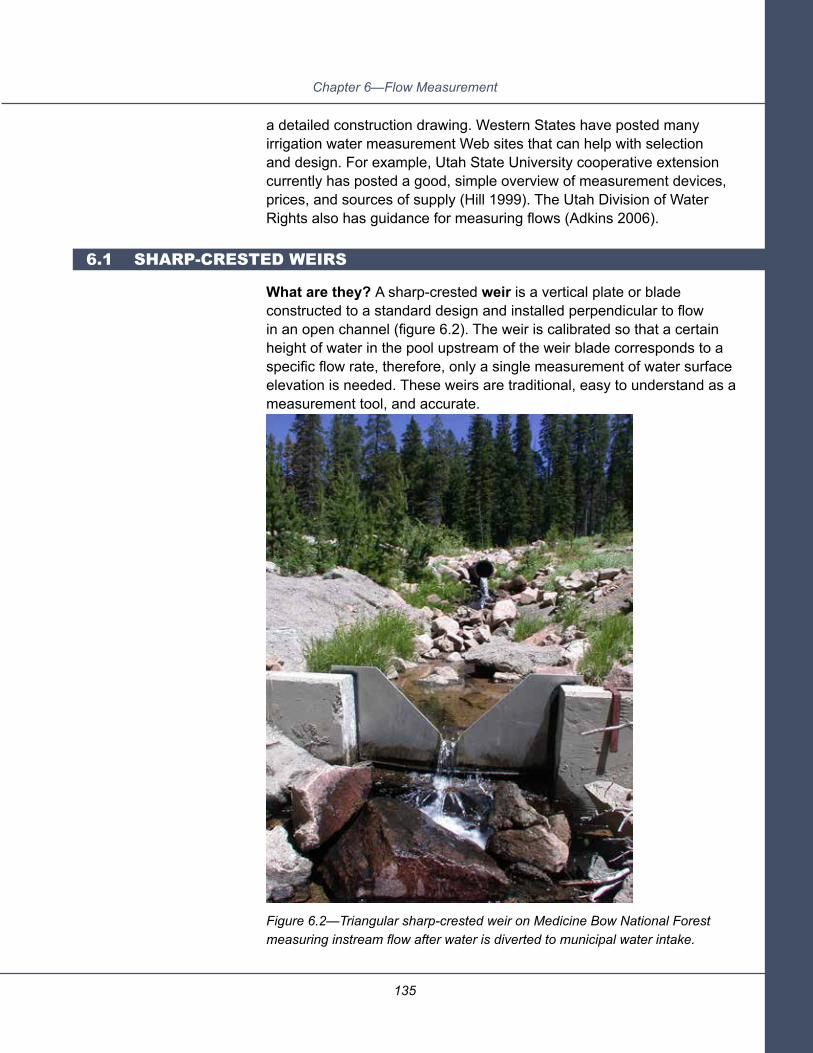
135
Chapter 6—Flow Measurement
a detailed construction drawing. Western States have posted many irrigation water measurement Web sites that can help with selection and design. For example, Utah State University cooperative extension currently has posted a good, simple overview of measurement devices, prices, and sources of supply (Hill 1999). The Utah Division of Water Rights also has guidance for measuring flows (Adkins 2006).
What are they? A sharp-crested weir is a vertical plate or blade constructed to a standard design and installed perpendicular to flow in an open channel (figure 6.2). The weir is calibrated so that a certain height of water in the pool upstream of the weir blade corresponds to a specific flow rate, therefore, only a single measurement of water surface elevation is needed. These weirs are traditional, easy to understand as a measurement tool, and accurate.
Figure 6.2—Triangular sharp-crested weir on Medicine Bow National Forest measuring instream flow after water is diverted to municipal water intake.
6.1 SHARP-CRESTED WEIRS

136
Planning and Layout of Small-Stream Diversions
The most common types of sharp-crested weirs are rectangular (figure 6.3), triangular (figure 6.2), and trapezoidal (Cipoletti). All have walls (bulkheads) between which the weir blade is set vertically. The weir blade has a fixed opening cut in its top edge (L in figure 6.3). This opening is called the weir notch; its bottom edge is the weir crest. The weir blade projects away from the bulkhead a minimum of two measuring depths (H in figure 6.3). Generally, a staff gauge is placed upstream of the weir blade 2 to 4 feet for reading water surface elevation at the correct point (greater than 3 times H from the weir blade). Flow in the approach pool must be uniform (no rapid constriction or expansion of flow), tranquil (no turbulence), and no faster than 0.5 feet per second over the entire range of measured flow. This effectively limits the use of sharp-crested weirs to mildly sloping, unlined ditches.
A major disadvantage of the sharp-crested weir is that water must fall freely over the weir, and the downstream water surface elevation must be at least 2 inches below the weir crest, generally at least 6 inches below the upstream water surface elevation. This means a substantial amount of head is lost across the weir.
Figure 6.3—Rectangular sharp-crested weir. Inset: detail of sharp-crested weir. The crest of a sharp-crested weir is narrow along the direction of flow and the falling water does not cling to the downstream edge of the blade.
HEAD WALL
STAFF GAUGE AT 3-4 HFROM WEIR
WEIR BLADE

137
Chapter 6—Flow Measurement
The different types of sharp-crested weirs can measure somewhat different flow rates. Table 6.1, at the end of the chapter, compares flow rates measurable by structures up to 5 feet wide. Although rectangular and trapezoidal weirs can be of any width, the “Water Measurement Manual” limits triangular weirs to a maximum width of 2.5 feet.
Where are they used? Sharp-crested weirs commonly are used at measuring points in unlined ditches where there is enough slope to lose 6 inches or so over the weir. The design is standardized, but dimensions are designed specifically for the site and the range of measured flows.
Sharp-crested weirs are very accurate at low flows, but they are not suitable for measuring large flows because they are easily submerged when the downstream water surface approaches the weir crest. Debris can be caught on the crest and sediment tends to deposit upstream of the weir. They do not work well in pipes or lined canals because the velocity of water approaching the weir must be less than 0.5 foot per second.
Installation. Sharp-crested weirs can be constructed of wood, aluminum, steel, or concrete. Metal installations are commonly prefabricated and can be hauled to the site on an ATV. Wood and concrete structures also can be prefabricated; however, this is not as commonly done. To be accurate, the weir must be constructed with the specified angles and dimensions. A common problem observed is the use of 2-inch boards for the crest, rather than a sharply beveled edge (Pearson 2002).
Care must be taken during installation to avoid seepage under or around the structure. The weir must be vertical and level across the top, and there must be an adequate difference in upstream and downstream water surface elevation to allow the weir to function properly. The ditchbanks must be high enough to prevent the ditch from overtopping upstream of the weir. Downstream scour protection is needed to protect the ditch bed and banks from the turbulence caused by water spilling over the weir crest. Bank erosion and undercutting are two of the common modes of weir failure.

138
Planning and Layout of Small-Stream Diversions
Operation and maintenance. If the staff gauge has a water level recorder, little operator attention is required except to ensure that sediment and debris are removed from the approach pool. Accurate measurements require that the approach section be clean (for tranquil, uniform, low velocity flow), so post-flood maintenance is essential. Weir measurement accuracy also depends on the weir plate being plumb and level. For that reason, weirs are vulnerable to vandalism, and measurements can be put at risk by tree roots and ice that may shift the weir.
What are they? Measuring flumes are shaped, open-channel flow sections that force flow to accelerate by converging the sidewalls, raising the bottom, or a combination of both. This causes the flow to pass through critical depth, which creates a unique water surface profile within the flume for each flow rate. As long as the crest is not backwatered, a single water-depth measurement upstream of the crest—at a distance three times the height of water over the crest—provides the flow measurement.
The most common flumes used to measure diversion flows are long-throated (also called broad-crested weirs or ramp flumes) and short-throated or Parshall flumes. Several specialized structures, such as H-flumes, cutthroat flumes, Palmer-Bowles flumes, flat-bottomed trapezoidal flumes, and special sediment-passing flumes are used under special circumstances. The “Water Measurement Manual” (Bureau of Reclamation 2001) contains information on these specialized weirs and their applications.
In long-throated flumes, the approach channel floor (invert) ramps up to a flat sill or crest extending across the entire structure (figure 6.4). At the end of the sill, a vertical drop or a gradual downstream ramp returns flow to normal depth. Short-throated or Parshall flumes have a series of segments with different floor slopes and wall angles that force the water through critical depth (figure 6.5). Because they are complex and less accurate than long-throated flumes, Parshall flumes are not recommended for new installations except where required due to laws or compact agreements.
6.2 MEASURING FLUMES

139
Chapter 6—Flow Measurement
Figure 6.4—Long-throated flume. (A) drawing. (B) Salmon Falls Canal, west of Rogerson, ID. (C) Twin Falls main canal below Milner Dam, ID.
B
A
C
STAFF GAUGE

140
Planning and Layout of Small-Stream Diversions
Figure 6.5—Parshall flume (A) drawing. (B) Parshall flume in an unnamed irrigation lateral west of Terrebonne, OR.
B
A
GAUGE
GAUGE
GAUGE

141
Chapter 6—Flow Measurement
Flumes have several advantages over sharp-crested weirs:
1. A wide range (0.03 to over 3,000 cfs) of flows can be measured us-ing various flume sizes.
2. For a given head drop, a flume can measure a wider range of flows than a sharp-crested weir.
3. Flume head loss is less than approximately one-fourth of that re-quired to operate a sharp-crested weir of the same control width.
4. The gradual convergence sections encourage the passage of sedi-ment and floating debris.
Where are they generally used? Long-throated (ramp) flumes can be used on both lined and unlined ditches, although in unlined ditches a sharp-crested weir or orifice would likely be less expensive to construct and install. They are less complex than short-throated flumes, can have customized cross sectional shapes, and are more accurate (±2 percent compared to ±5 percent for short-throated flumes).
For flumes, as for weirs, approach flow should be tranquil and uniform. Approach velocity should be higher than for sharp-crested weirs—between 1 and 3 feet per second. Ramp flumes are less sensitive to backwatering than other devices, so they might be appropriate where water surface elevation in the ditch varies, such as where the farmer puts in a ditch plug to irrigate a field. Ramp flumes also can be designed to fit in pipes or in ditches of various cross-section shapes, which saves the installer from having to reshape the ditch to accommodate the flume. The upstream banks must be high enough to prevent overtopping, and scour protection is needed downstream, especially when using short-throated flumes.
Accurate flow measurement requires free flow across the structure. If downstream backwater (in flat landscapes or where flow resistance increases downstream) comes close to drowning critical depth in the flume, two head measurements are required to quantify flow, resulting in significant loss of accuracy compared to free-flow measurement techniques.

142
Planning and Layout of Small-Stream Diversions
Installation. Flume designs are standardized, and customized prefabricated units with calibration tables can be ordered commercially (see for example, NuWay flumes). More commonly, flumes are made to specified dimensions by a fabrication shop. Computer programs such as WinFlume can be used to calibrate long-throated flumes. However, most flumes can be designed quickly and more easily by an engineer for the specific conditions of the site: bank height, slope, and range of flows to measure.
Flumes can be constructed of wood, concrete, galvanized sheet metal, or other materials. They can be prefabricated and hauled on an ATV, and small structures can even be completely constructed offsite and placed in one piece. Like weirs, flumes have moderate-to-high installation costs. They may be somewhat more expensive to construct because they are longer than weirs and require more material. If installation is done separately from other work, and an excavator is mobilized, a steel flume for a 3-foot ditch might cost as much as $3,000.
One problem observed with owner-fabricated units is that structure dimensions may be slightly off, which reduces measurement accuracy. Flumes must also be level to measure flow accurately, so precision is important during installation. The staff gauge location also is critical to accuracy.
Flumes require bank and streambed protection to avoid undercutting and lateral erosion. They also should have collars or antiseep walls to reduce seepage through the banks adjacent to the structure, and ensure that as much as possible of the diverted flow is measured.
Operation and maintenance. Requirements are reading and recording the staff gauge to keep the flow record, and clearing the approach pool of sediment and debris. Sediment and debris collecting in the approach section are common causes of inaccurate readings. Flumes should be checked annually to ensure they remain level.

143
Chapter 6—Flow Measurement
What are they? A submerged orifice is an opening below the water surface through which water flows (see section 3, headgates). Orifices constructed for use as flow measuring devices are well-defined, sharp-edged openings in a wall or bulkhead. For irrigation use, circular or rectangular orifices commonly are placed in vertical surfaces perpendicular to the direction of flow (figure 6.6). One type of ditch headgate—a sliding gate on the end of a smooth or corrugated pipe (ARMCO)—has been empirically calibrated as a measurement device, a meter gate (Cadena and Magallanez 2005). Observation wells or cylinders on either side of the meter gate provide upstream and downstream head measurement. Meter gates typically are purchased as separate systems from commercial suppliers who supply tables for flow rate determination (Bureau of Reclamation 2001).
Figure 6.6—Rectangular submerged orifice drawing.
Submerged orifices measure relatively large flows with little head loss (i.e., only a small drop in water surface). This allows them to conserve delivery head in comparison to the losses associated with flumes or weirs.
6.3 SUBMERGED ORIFICES
STAFF GAUGE A
STAFF GAUGE B
144
Planning and Layout of Small-Stream Diversions
To determine the flow rate, the size and shape of the orifice and the change in water surface elevation across the flume must be known (figure 6.6). Two head measurements (upstream and downstream) are required. Commercial devices come with calibration tables that show flow for any combination of upstream and downstream water surface elevation. If the orifice is operating in a free flow situation (i.e., not submerged), then only an upstream head measurement is required.
Where are they generally used? Orifices conserve available head and are useful in situations where insufficient fall is present for weir flow measurements. They also require less space than weirs or flumes. The water should be screened or fairly clean of debris since orifices are prone to plugging with debris.
Installation. Installation involves excavating the ditch, constructing wingwalls and headwalls, setting and leveling the structure, and backfilling and stabilizing the installation. Verify that the orifice as installed reads as designed, that is, measure the flow with a different method and compare it with the discharge listed on the calibration table for the head difference. Calibrating the orifice is vital, since field conditions must match closely those assumed in orifice design.
Typically, stand-alone orifices are more expensive and less accurate than sharp-crested weirs and some long-throated flumes. Naturally, the expense depends on the availability of material and construction equipment. An orifice measuring device can be quite inexpensive where it is included with another system component, such as in figure 6.7, where it is part of the fish screen.

145
Chapter 6—Flow Measurement
Figure 6.7—A rectangular orifice flow measurement component is designed into this modular vertical flat plate fish screen, designed by Pat Schille, and constructed at the Yakima, WA, screen shop.
Operation and Maintenance. Orifice measurements are more time-consuming and require somewhat more effort than weir or flume measurements: you have to read water surface elevation on both sides of the orifice, figure the difference, and then read the flow from the calibration table.

146
Planning and Layout of Small-Stream Diversions
Orifices are the water measuring structures most susceptible to debris accumulations. They are less likely than a weir or flume to accumulate sediment. Accumulations of either debris or sediment upstream of the orifice can alter flow conditions and result in inaccurate measurements, so regularly clearing debris and sediment from the area is an important operational chore. If the orifice is completely blocked, the structure can overtop and even fail.
Table 6.1 is a comparison of measurable flow ranges and head loss for structures approximately 4- to 5-feet wide. All structures except for triangular weirs can be made much larger and can measure larger flows. Recalibration is necessary for flow measurement in cases where structures vary from standard size and configuration.
StructureType
Rectangular Weir (contracted)2
Triangular Weir
Cipoletti (trapezoidal) Weirs
Short-Throated Flume(Parshall flume)
Long-Throated Flume (broad-crested weir)3
Submerged Rectangular Orifice4
Maximum Flow(cfs)
33.5
4.3
33.5
85.6
64
4.38
Minimum Flow(cfs)
0.12
0.5
0.13
2.22
7.6
0.49
Minimum Head Loss
(ft)1
0.05
0.05
0.05
0.33
0.13
0.1
Sharp-crested weirs
Broad-crested weirs
Submerged orifices
Table 6.1—Comparison of measurable flow ranges and head loss for structures approximately 4- to 5-feet wide
1 Minimum headloss across the weir for an accurate measurement with a single upstream measurement (weirs and flumes).
2 Flows for sharp-crested weirs are shown for head above weir crest of 1.99 ft. Weir width, excluding wingwalls, is approximately 4 ft.
3 Channel side slopes of 1.5:1, bottom width of 2.0 ft, maximum canal depth of 4.0 ft.4 Orifice cross-sectional area of 1.0 ft2 and head differential from 0.01 ft to 0.80 ft.

147
Chapter 7—Operations, Monitoring, and Maintenance Plan
An operations, monitoring, and maintenance (OM&M) plan should be prepared in conjunction with any diversion upgrade and/or permit renewal. The purpose of the OM&M plan is to identify clearly what actions are required to maintain effective and efficient operations that limit the diversion’s impact on the stream channel, riparian area, water quality, and aquatic species. The plan should address infrastructure requirements, routine maintenance needs, hazards, and environmental factors. Examples might be actions to deal with corrosive or unstable soils, corrosive water, storage of fuels and lubricants, the effects of recent fires or floods, aquatic species movement needs, winter shutdown, spring runoff, and summer storm adjustments. Typically, the engineer/designer or manufacturer of a system will provide a basic OM&M plan.
Table 7.1 presents general summaries of required activities for each component of a diversion facility. These summaries may be useful as a basis for constructing your own OM&M plan, which should be geared specifically to the site, the installation, its recent history, and to the water user’s needs and interests.
Cha
pter
7—
Ope
rati
ons,
Mon
itor
ing,
and
Mai
nten
ance
Pla
n

148
Planning and Layout of Small-Stream Diversions
OM
&M
act
ions
requ
ired
Ann
ually
Fill
conv
eyan
ce s
yste
m
with
wat
er a
t beg
inni
ng
of s
easo
n; d
ewat
er
at e
nd o
f sea
son.
Cle
an o
ut s
edim
ent
accu
mul
atio
ns.
Insp
ect f
or a
nd re
pair
dam
age
from
ani
mal
s,
ice,
van
dals
, fire
, floo
d,
tree
root
s, e
xces
sive
ve
geta
tion
grow
th,
and
so fo
rth.
Insp
ect f
or e
xpos
ed o
r er
oded
ban
ks: r
epai
r an
d re
seed
.
Syst
em
Com
pone
nt
Wat
er
Con
veya
nce
to
Use
r (di
tch,
pip
e,
cana
l)
Dai
ly
Adj
ust h
eadg
ate
to
mai
ntai
n de
sire
d flo
w
and
requ
ired
freeb
oard
(d
aily
che
cks
and
adju
stm
ents
like
ly
need
ed in
spr
ing
or
whe
n flo
ws
vary
).
Wee
kly
Insp
ect f
or a
nd re
pair
dam
age
caus
ed b
y an
imal
s (b
eave
rs,
grou
nd s
quirr
els,
an
d so
forth
).
Insp
ect m
echa
nica
l ap
purte
nanc
es (w
aste
w
ays
and
gate
s) a
nd
repa
ir as
nee
ded.
Mon
thly
/Per
iodi
cally
Insp
ect f
or e
xces
s ve
geta
tion
grow
th;
clea
r if n
eede
d.
Insp
ect f
or a
nd
repa
ir da
mag
e fro
m
unco
ntro
lled
stor
m
runo
ff.
Che
ck fr
eebo
ard
durin
g m
axim
um w
ater
di
vers
ions
—m
ay b
e ne
eded
dai
ly in
spr
ing.
Tabl
e 7.
1—O
M&
M a
ctio
ns re
quire
d

149
Chapter 7—Operations, Monitoring, and Maintenance Plan
Ann
ually
Adj
ust a
nd ti
ghte
n op
erat
or b
olts
.
Cle
ar o
ut s
edim
ent
accu
mul
atio
ns.
Insp
ect f
or a
nd re
pair
dam
age
from
ice,
va
ndal
s, fi
re, fl
ood,
tree
ro
ots,
mos
s bu
ild-u
p, a
nd
so fo
rth.
Che
ck s
eal a
nd re
pair
as
need
ed to
pre
vent
wat
er
from
ent
erin
g di
tch
whe
n cl
osed
.
Insp
ect f
or a
nd re
pair
dam
age
from
ice,
va
ndal
s, fi
re, fl
ood,
tree
ro
ots,
mos
s bu
ildup
, and
so
forth
.
Rep
air a
ny e
rode
d ba
nks
(esp
ecia
lly in
dow
nstre
am
scou
r poo
l).
Syst
em
Com
pone
nt
Hea
dgat
e
Div
ersi
on
Stru
ctur
e
Dai
ly
Adj
ust a
nd c
ontro
l flow
.
Che
ck fo
r deb
ris
accu
mul
atio
n.
Adj
ust s
topl
og o
r gat
e po
sitio
n to
mai
ntai
n re
quire
d di
vers
ion
flow
.
Wee
kly
Che
ck fo
r and
rem
ove
debr
is a
nd s
edim
ent
accu
mul
atio
ns.
Insp
ect f
or a
nd re
pair
dam
age
caus
ed b
y an
imal
s (b
eave
rs, g
roun
d sq
uirr
els,
and
so
forth
).
Insp
ect f
or a
nd re
mov
e se
dim
ent a
nd d
ebris
ac
cum
ulat
ions
.
Rec
ord
chan
ges
mad
e to
st
oplo
g or
gat
e op
erat
ing
setti
ngs.
Insp
ect f
or a
nd re
pair
dam
age
caus
ed b
y an
imal
s (b
eave
rs, g
roun
d sq
uirr
els,
and
so
forth
)
Mon
thly
/Per
iodi
cally
Insp
ect f
or a
nd c
lear
ex
cess
veg
etat
ion
grow
th.
Insp
ect f
or a
nd re
pair
dam
age
caus
ed b
y w
eath
er.
Lubr
icat
e ga
te s
tem
(le
adas
crew
) sem
i an
nual
ly.
Insp
ect f
or a
nd c
lear
ex
cess
veg
etat
ion
grow
th.
Tabl
e 7.
1—O
M&
M a
ctio
ns re
quire
d (c
ontin
ued)
OM
&M
act
ions
requ
ired

150
Planning and Layout of Small-Stream Diversions
Ann
ually
Insp
ect f
or h
igh
velo
city
ar
eas.
The
app
roac
h ch
anne
l may
hav
e ch
ange
d, a
lterin
g ho
w
wat
er e
nter
s th
e sc
reen
.
Syst
em
Com
pone
nt
Fish
Scr
een
Not
e: In
man
y ca
ses,
an
agen
cy o
r or
gani
zatio
n pr
ovid
es
the
fish
scre
en o
r fis
hway
. Ens
ure
the
dive
rter a
nd a
genc
y ac
know
ledg
e an
y po
tent
ial c
onfli
cts
and
agre
e on
how
to
oper
ate
the
dive
rsio
n.
Dai
ly
Rem
ove
float
ing
debr
is
from
scr
een
surfa
ce.
Che
ck to
ens
ure
clea
ning
sy
stem
is o
pera
ting
as
need
ed.
Che
ck s
cree
n fo
r da
mag
e.
Che
ck fr
eebo
ard
durin
g m
axim
um w
ater
di
vers
ions
.
Insp
ect b
ypas
s pi
pelin
e en
tranc
e to
ens
ure
it is
free
from
deb
ris a
nd
sedi
men
t blo
ckag
e an
d ha
s ad
equa
te fl
ow.
Wee
kly
Che
ck fo
r fish
pas
sing
ov
er, t
hrou
gh, o
r aro
und
scre
en; r
epai
r as
need
ed.
Lubr
icat
e be
arin
gs a
nd
mec
hani
cal c
ompo
nent
s of
the
scre
en c
lean
er.
Insp
ect f
or a
nd re
mov
e se
dim
ent a
ccum
ulat
ions
.
Insp
ect f
or a
nd re
pair
dam
age
caus
ed b
y an
imal
s (b
eave
rs, g
roun
d sq
uirr
els,
and
so
forth
).
Adj
ust fl
ow th
roug
h sc
reen
if n
eces
sary
and
en
sure
flow
is d
istri
bute
d as
eve
nly
as p
ossi
ble
acro
ss th
e sc
reen
.
Mon
thly
/Per
iodi
cally
Insp
ect f
or a
nd c
lear
ex
cess
veg
etat
ion
grow
th.
Tabl
e 7.
1—O
M&
M a
ctio
ns re
quire
d (c
ontin
ued)
OM
&M
act
ions
requ
ired

151
Chapter 7—Operations, Monitoring, and Maintenance Plan
Ann
ually
Rep
air a
ny e
rosi
on o
n en
tranc
e an
d ex
it po
ol
bank
s.
Insp
ect f
or a
nd re
pair
dam
age
caus
ed b
y ic
e,
vege
tatio
n (tr
ee ro
ots,
m
oss
build
up),
flood
s,
vand
als,
or fi
re.
Che
ck d
evic
e is
leve
l.
Syst
em
Com
pone
nt
Fish
way
(ups
tream
pa
ssag
e)
Wat
er
Mea
sure
men
t D
evic
es
Dai
ly
Insp
ect fi
shw
ay e
ntra
nce
to e
nsur
e it
is fr
ee fr
om
debr
is a
nd s
edim
ent
bloc
kage
.
Insp
ect o
utfa
ll an
d m
easu
re fl
ow ra
te to
en
sure
suf
ficie
nt fl
ow
dept
h an
d di
scha
rge
pool
de
pth
are
prov
ided
for
fish
pass
age.
Che
ck fo
r and
rem
ove
debr
is c
augh
t in
upst
ream
ap
proa
ch re
ach
or o
n cr
est o
f dev
ice.
Wee
kly
Insp
ect f
or a
nd re
pair
dam
age
caus
ed b
y an
imal
s (b
eave
rs, g
roun
d sq
uirr
els,
and
so
forth
).
Che
ck fo
r sed
imen
t ac
cum
ulat
ion
in u
pstre
am
appr
oach
reac
h (d
epos
its w
ill in
crea
se
wat
er s
urfa
ce e
leva
tion
and
inte
rfere
with
flow
m
easu
rem
ent).
Rem
ove
as n
eede
d.
Insp
ect f
or a
nd re
pair
dam
age
caus
ed b
y an
imal
s (b
eave
rs,
grou
nd s
quirr
els)
.
Mon
thly
/Per
iodi
cally
Rem
ove
exce
ss
vege
tatio
n.
Rem
ove
exce
ss
vege
tatio
n.
Tabl
e 7.
1—O
M&
M a
ctio
ns re
quire
d (c
ontin
ued)
OM
&M
act
ions
requ
ired


153
Glossary/Bibliography
An anchor: a heavy object buried in the streambed and chained to a log or other weir component to stabilize it and prevent it from floating away.
The bankfull channel is the channel width, depth, or area filled with water just as rising water spills onto the flood plain. Bankfull flow is often described as a channel-forming flow because it is a frequently occurring high flow that, in many channels, transports the most sediment and correlates with channel size (Emmett and Wolman 2001). See Forest Service Stream System Technology Center DVD: “Identifying Bankfull Stage in the Eastern and Western United States.”
For any open channel cross section, each flow rate has two depths: a higher depth at subcritical flow and a lower depth at faster supercritical flow. Critical depth is the boundary between the two. Critical depth is important in flow measurements because a single depth measurement uniquely defines water velocity. Many flow measurement structures are designed to force water to critical depth through a known cross sectional area, so that flow rate can be read off a calibration table.
Fines include fine gravel, sand, silt, and clay.
Head describes the energy in a mass of water. For diversion planning purposes, it can be thought of as the elevation of the water surface above a reference level, such as the channel bed, the ditch bed, the floor of a hydraulic structure, or the point of water use. Velocity and pressure are also components of head, but they can usually be neglected in diversion planning.
For the purposes of diversion planning, head loss is the decrease in water surface elevation between two points (section 3.2).
A structure is outflanked when water runs around it instead of over or through it. This may happen during a flood if the streamwater surface rises higher than the walls of the structure.
Piping is erosion caused by water percolating through soil (or an earthen dam). This type of erosion results in small tunnels inside the soil mass (soil pipes), which enlarge as water progressively concentrates and removes more soil particles.
A mixture of rocks is poorly graded when the rocks are uniform in size. Because the particles are all similar in size, smaller particles are not present to fill the spaces between them, so these mixtures have continuous pore spaces through which water can move relatively rapidly. Meaning is the same as well sorted.
Ballast
Bankfull channel
Critical depth
Fines
Head
Head loss
Outflanked
Piping
Poorly graded
Glo
ssar
y/B
iblio
grap
hy

154
Planning and Layout of Small-Stream Diversions
Thalweg
Unentrenched (channels)
Uniform (flow)
A thalweg is a line connecting the deepest points in the channel from upstream to downstream along the streambed (see figure 2.2).
Entrenchment refers to vertical confinement of a channel (Rosgen 1994). Unentrenched channels have wide flood plains where floodwaters can spread out, slow down, and drop their sediment and debris loads. Unentrenched channels often meander across a relatively flat valley floor, and erosion on the outsides of meander bends can cause these channels to shift location and alignment. Streambanks are often low and erodible where vegetation has been removed.
Uniform flow is straight, without expansions, contractions, or turbulence.

155
Glossary/Bibliography
Adams, S.B; Schmetterling, D.A.; Young, M.K. 2005. Instream movements by boreal toads. Herpatology Review 26(1): 27-33.
Adkins, G. B. 2006. Flow measurement devices. Utah Division of Water Rights. Online at <http://waterrights.utah.gov/distinfo/measurement_devices.pdf>. Accessed 4/23/2010.
Bates, K.K. 2006. Assessment of diversion related structures within the Sawtooth National Recreation Area. Prepared for the Sawtooth National Recreation Area and USDA Forest Service. Boise, ID: U.S. Department of Agriculture, Forest Service, Intermountain Region,
Instream Flow Group.
Bates, K.K.; Love, M. (in preparation). Modifying culverts for fish passage. San Dimas, CA: U.S. Department of Agriculture, Forest Service, National Technology and Development Program.
Bohn, C,C.; King, J.G. 2000. Stream channel responses to stream flow diversion on small streams of the Snake River drainage, Idaho. RMRS-RP-20. Ogden, UT: U.S. Department of Agriculture, Forest Service, Rocky Mountain Research Station.
Bureau of Reclamation. 2001. Water measurement manual. 3rd edition. Washington, DC: U.S. Government Printing Office. Online at <http://www.usbr.gov/pmts/hydraulics_lab/pubs/wmm/>. Accessed 4/23/2010.
Bureau of Reclamation. 2009. The WinFlume Home Page. <http://www.usbr.gov/pmts/hydraulics_lab/winflume/>. Accessed 4/23/2010.
Cadena, F.; Magallanez, H. 2005. Analytical solution for circular gates as flow metering structures. J Irrigation and Drainage 131(5): 451-456.
California Department of Fish and Game. 2009. Fish passage design and implementation. Part XII of the California salmonid stream habitat restoration manual. Online at <http://www.dfg.ca.gov/fish/REsources/HabitatManual.asp>. Accessed 4/23/2010.
Colyer, W. 2010. Personal communication. September 14, 2010.
Emmett, W.W.; Wolman, M.G. 2001. Effective discharge and gravel bed rivers. Earth Surface Processes and Landforms. 26: 1369-1380.
A
B
E
C

156
Planning and Layout of Small-Stream Diversions
Federal Interagency Stream Restoration Working Group. 2001. Stream corridor restoration: principles, practices, and processes. U.S. Department of Agriculture, Natural Resources Conservation Service National Engineering Handbook 653. Online at <http://www.nrcs.usda.gov/technical/stream_restoration/>. Accessed 5/17/2010.
Forest Service Stream-Simulation Working Group. 2008. Stream simulation: an ecological approach to providing passage for aquatic organisms at road-stream crossings. San Dimas, CA: U.S. Department of Agriculture, Forest Service, National Technology and Development Program. Online at <http://www.stream.fs.fed.us/fishxing/aop_pdfs.html>. Accessed 4/23/2010.
Gale, S.B.; Zale, A.V. 2008. Effectiveness of fish screens to prevent entrainment of westslope cutthroat trout into irrigation canals. North American Journal of Fisheries Management. 28(5): 1541-1553.
Heiner, B.J. 2009. Parshall flume staff gauge location and entrance wingwall discharge calibration corrections. Logan, UT: Utah State University, Department of Civil and Environmental Engineering. Master’s Thesis. Online at <http://digitalcommons.usu.edu/
etd/480>. Accessed 3/3/10.
Hill, R. 1999. How good is your water measurement? Logan, UT: Utah State University Cooperative Extension AG/BIE/WM/01. Online at <http://extension.usu.edu/files/publications/publication/AG_BIE_WM_01.pdf>. Accessed 4/23/2010.
Moulton, M. 2010. Personal communication. Review comments transmitted via email to K. Clarkin 6/10/2010.
National Oceanic and Atmosphere Administration, National Marine Fisheries Service. 2008. Anadromous salmonid passage facility design. Portland, OR: National Marine Fisheries Service, Northwest Region.
Northcote, T.G. 1998. Migratory behavior of fish and its significance to movement through riverine fish passage facilities. In Fish Migration and Fish Bypasses. 1998. Jungwirth, M.; Schmutz, S.; Weiss, S., eds. Oxford, England: Fishing News Books, Oxford, England.
Pearson, K.E. 2002. Irrigation water measurement. Agronomy Note #348. Bozeman, MT: Montana State University Extension. Online at <http://agnotes.org/AgNotes/docs/348.htm>. Accessed 4/23/2010.
P
NM
H
G
F

157
Glossary/Bibliography
Rosgen, D. L. 1994. A classification of natural rivers. Catena. 22: 169-199.
Rosgen, D. L. 2001. The cross-vane, W-weir, and J-hook vane structures: their description, design and application to stream stabilization and river restoration. Fort Collins, CO: Wildland Hydrology Inc. Online at <http://www.wildlandhydrology.com/assets/cross-vane.pdf>. Accessed 4/24/2010.
Schmetterling, D.A.; Adams, S.B. 2004. Summer movements within the fish community of a small montane stream. North American Journal of Fisheries Management 24:1163-72.
U.S. Department of Agriculture, Forest Service. 2003. Identifying bankfull stages in the eastern and western United States. DVD. Fort Collins, CO: U.S. Department of Agriculture, Forest Service, Rocky Mountain Research Station, Stream Systems Technology Center.
U.S. Department of Agriculture, Forest Service, Watershed, Fish, Wildlife, and Rare Plants Staff. [In preparation]. Water rights and uses site visit field guide. Washington, DC.
U.S. Department of Agriculture, Natural Resources Conservation Service. 2001. Design of rock weirs. Engineering Technical Note 13. Online at <ftp://ftp-fc.sc.egov.usda.gov/ID/technical/technotes/engineering/eng_tn13.pdf>. Accessed 4/23/2010.
U.S. Department of Agriculture, Natural Resources Conservation Service. 2007a. Flow-changing techniques. National Engineering Handbook Part 654-Technical Supplement 14H. Online at <http://directives.sc.egov.usda.gov/OpenNonWebContent.aspx?content=17817.wba>. Accessed 12/21/10.
U.S. Department of Agriculture, Natural Resources Conservation Service. 2007b. Grade control structures. National Engineering Handbook Part 654-Technical Supplement 14G. Online at <http://directives.sc.egov.usda.gov/OpenNonWebContent.aspx?content=17816.wba>. Accessed 12/21/10.
Washington Department of Fish and Wildlife. [2000 draft] Fish protection screen guidelines for Washington State. Online at <http://wdfw.wa.gov/hab/ahg/screen51.pdf>. Accessed 4/21/2010.
Washington Department of Fish and Wildlife. [2000 draft] Fishway guidelines for Washington State. Online at <http://wdfw.wa.gov/hab/ahg/fishguid.pdf>. Accessed 4/23/2010.
Witte, L. G. 2001. Still no water for the woods. Salt Lake City, UT: ALI-ABA Federal Lands Law Conference. Oct 19, 2001.
R
SU
W


Appendix A—Site Assessment Checklists
159
DIVERSION STRUCTURE SITE DATA CHECKLIST
Diversion Name: _________________________ Stream: ________________________________
Site ID: _________________________________ Tributary to: _____________________________
Prepared By: ____________________________ Date: __________________________________
Weather: _______________________________ Time: __________________________________
Location(lat/long): ________________________ Map Reference: _________________________
Water Right Owner: _______________________ Phone No.:______________________________
Owner’s Address: __________________________________________________________________
_________________________________________________________________________________
_________________________________________________________________________________
Water Right No.: ___________________________________________________________________
Total Possible Diversion Flow: ________________________________________________________
Type of Diversion: __________________________________________________________________
_________________________________________________________________________________
_________________________________________________________________________________
Diversion Condition: ________________________________________________________________
_________________________________________________________________________________
_________________________________________________________________________________
In-stream Fish Passage Issues: _______________________________________________________
_________________________________________________________________________________
_________________________________________________________________________________
App
endi
x A
—S
ite
Ass
essm
ent
Che
cklis
t

160
Planning and Layout of Small-Stream Diversions
Available Written Comments/key points for field visit Information
Site Assessment
Design Report
Construction Drawings
O&M Plan
Watershed Plan
TMDL Study
Grant Application
1 Indicate items available and check if reviewed.
41

Appendix A—Site Assessment Checklists
161
INFR
AS
TR
UC
TU
RE
OB
SE
RV
AT
ION
S
Stru
ctur
e Ty
pe (d
escr
ibe)
Pr
esen
t/Eva
luat
ed6
Con
ditio
n D
escr
iptio
n an
d Ph
oto
No.
Div
ersi
on S
truct
ure
Fish
Scr
een
Fish
Byp
ass
Wat
er M
easu
ring
Dev
ice
Flow
Con
trol
Oth
er
6 If s
truct
ure
is p
rese
nt b
ut n
ot e
valu
ated
= P
; if s
truct
ure
was
eva
luat
ed =
E

162
Planning and Layout of Small-Stream Diversions
Prob
lem
Sed
imen
t Dep
ositi
on
Ero
sion
/Hea
dcut
s S
tream
Bed
Sco
ur/D
egra
datio
n
Late
ral C
hann
el In
stab
ility
Ditc
h Fa
ilure
s
Aqu
atic
Ani
mal
Pas
sage
Ups
tream
and
D
owns
tream
Ope
ratio
n an
d M
aint
enan
ce
Oth
er:
Con
ditio
n
Geo
logy
/Soi
ls
Stre
am T
ype
Stru
ctur
es
Land
Ow
ners
hip
Arc
haeo
logy
Vege
tatio
n
Aqu
atic
and
terr
estri
al b
iota
Evid
ence
Pot
entia
l con
stra
int o
n di
vers
ion
loca
tion,
layo
ut a
nd/o
r des
ign
See
list
of c
omm
on c
onst
rain
ts in
tabl
e 2.
2
See
list
of c
omm
on p
robl
ems
in ta
ble
2.1
SIT
E C
ON
DIT
ION
S

Appendix A—Site Assessment Checklists
163
FLO
W
Fl
ow C
ondi
tion
Div
erte
d Fl
ow
Met
hod
of D
eter
min
atio
n St
ream
Flo
w
Met
hod
of D
eter
min
atio
n
S
ite V
isit
Flow
M
ax D
iver
sion
Flo
w
S
tock
Wat
er F
low
H
igh
Run
off F
low
7
7 Div
ersi
on d
esig
ners
typi
cally
use
the
25-y
ear fl
ow a
s th
e hi
gh d
esig
n flo
w. T
he re
curr
ence
inte
rval
can
be
high
er if
reso
urce
pr
otec
tion
war
rant
s.
SIT
E S
KE
TCH
Incl
ude
dow
nstre
am a
nd u
pstre
am s
urve
y en
dpoi
nts,
cha
nnel
alig
nmen
t, ch
anne
l fea
ture
s (p
ools
, sed
imen
t acc
umul
atio
n),
dive
rsio
n st
ruct
ure/
dam
, ditc
h/pi
pe e
ntra
nce
and
alig
nmen
t, fis
h sc
reen
, byp
ass,
wat
er m
easu
rem
ent s
truct
ure,
cro
ss s
ectio
n lo
catio
ns.

164
Planning and Layout of Small-Stream Diversions
DIVERSION SITE SURVEY
This survey data form includes the minimum number of points needed for planning upgrades at a site with no existing fish screen or bypass channel. The form should be expanded (or data taken in a field book) to accommodate other points that may be important to describe your site. For a typical diversion site, the graphic shows the general area where each point would be taken; locations may vary for different types of diversions. See table 2.3 in chapter 2 for explanation of points.
Temporary benchmark(s): Elevation________ Description:____________________________________
Longitudinal Profile Notes Measurement Points BS FS (water depth (thalweg) (+) HI (-) Elevation for survey point)Beginning of Profile: Downstream
Downstream Cross Section
Pool Tail-out/Riffle crest
Pool Maximum Depth
Thalweg Below Dam
Dam Crest
Immediately Above Dam
Opposite Ditch
Ditch Entrance/Headgate
Ditch Bank at Headgate, Right/Left
Upstream Cross Section
End of Profile (Upstream)
Ditch, 100-200 ft Down Ditch from Headgate
Ditch Bank 100-200 ft Down Ditch From Headgate, Right/Left

Appendix A—Site Assessment Checklists
165
Downstream Cross Section at LP _______’
Longitudinal Profile Notes Measurement Points BS FS (water depth (thalweg) (+) HI (-) Elevation for survey point)
Left Endpoint
Top Left Bank
Bottom Left Bank
Left Edge of Water
Thalweg
Right Edge of Water
Bottom Right Bank
Top Right Bank
Right Endpoint
Upstream Cross Section at LP _______’
Left Endpoint
Top Left Bank
Bottom Left Bank
Left Edge of Water
Thalweg
Right Edge of Water
Bottom Right Bank
Top Right Bank
Right Endpoint

166
Planning and Layout of Small-Stream Diversions
Other Survey Observations
Headgate Size _____________________________________________________________________
Ditch Width _______________________________________________________________________
High Water Elevations Where Measured (Distance on LP)
_________________ ________________
_________________ ________________
_________________ ________________
_________________ ________________
TYPICAL SITE PLAN WITH MINIMUM LONGITUDINAL PROFILE SURVEY POINTS

Appendix B—Automating River Diversions
167
Demand for water in and from national forests continues to increase; and water temperature, water quality, and in-stream and riparian habitats are being managed with increasing care and administrative oversight.
The emerging need to improve management of surface-water diversions to maintain desired in-stream flows clearly is apparent.
Flow management criteria in the future will not only need to specify the amount of water diverted under a water right, but also the amount left in the stream. How might these water management criteria be met? Hand-controlled ditch gates and onsite flow measurement by reading a gauge may be effective enough in some cases; however, traditional methods may not permit rapid enough response to flow changes in the river where:
● Water is scarce.
● Withdrawals must be coordinated with multiple users.
● Habitat for threatened or endangered aquatic species is at risk.
● Ditch overtopping would do environmental damage.
New irrigation systems also require flexible water delivery. In the past, water users typically received a constant flow rate on a predetermined schedule, and this was often adequate for managing their surface irrigation systems. However, as the variety of irrigation systems has increased, the need for more flexible flow management, both in timing and quantity, has become apparent. For example, end guns on center pivot systems turn on and off, and microirrigation systems irrigate different-sized fields on schedules based on the weather (evapotranspiration rates and precipitation).
A river diversion typically has several primary functions, including:
● On/off control of water.
● Flow rate control.
● Flow rate measurement.
● Volumetric measurement (Burt 2010).
App
endi
x B
—A
utom
atin
g R
iver
Div
ersi
ons

168
Planning and Layout of Small-Stream Diversions
Automating the functions of an irrigation turnout is becoming increasingly common, as the available technology improves, and as farmers’ management practices require additional flexibility. Remote control and monitoring of flow rates throughout a whole system is also possible. Automation does not necessarily imply complexity, as shown in figure B.1 (an example of a float control).
A float control maintains a constant water level upstream or downstream of the head gate (figure B.1). With the downstream water level at the pivot axis, the gate is balanced so that the moment caused by the center of gravity about the hinge is equal to the moment caused by the upthrust of the float. Any change in the water level alters this stability, causing the gate to rotate. The resulting increase or decrease in discharge restores the water level to the pivot centerline. The float control requires no power and little maintenance as long as the diversion is screened to keep trash from interfering with gate operation.
One disadvantage of the float gate from the water user’s perspective is the difficulty in changing the setting or making adjustments. Also the flow rate can vary as the gate adjusts to maintain the desired upstream or downstream water level. For more information, see flap-gate design information from the Irrigation Training and Research Center (ITRC 2007).
Figure B.1—Automatic float gate used to maintain constant water level on the inlet screen for the Hood River Canal Diversion, Hood River, OR. Only the closer gate is operating, and it is adjusting to keep the upstream (on left) water level the same. The float or ballast is the round tube at the end of the levered gate.

Appendix B—Automating River Diversions
169
Another simple automated setup for flow monitoring might be a water level sensor on a flume or weir with a datalogger that is downloaded by hand.
More complex automated systems improve the flexibility and responsiveness of diversion management with remote monitoring and headgate-control functions. Supervisory Control and Data Acquisition (SCADA) systems are used in industry to monitor and control complex processes for manufacturing plants, power grids, and pipelines. As water-user demands and regulatory requirements continue to rise, irrigation districts and other water users have begun to deploy SCADA systems to better manage water withdrawals and distributions. Some systems also aim to make the system transparent to all users by providing real-time flow monitoring data via the Internet (see, for example, the Sevier River Water Users Association Virtual River Basin 2011).
The costs associated with installing SCADA components will probably limit their application for small diversions on National Forest System lands for some time. However, that may no longer be true for larger installations. The technology is changing rapidly, and as electronic components come down further in cost, increase their functionality, and become more robust for field use, the economic feasibility of remote monitoring and control will increase. At a minimum, these systems are worth knowing about as potential future tools.
Unlike the independent systems described above, many SCADA systems include data transmission to a base station computer for remote monitoring and/or control. Several levels of SCADA systems can be generally identified (Smith and Magnuson 2005):
● Monitor only (likely lowest cost).
● Monitor and manual remote control.
● Local automated control.
● Full gate or canal automation (likely highest cost).
SCADA systems for diversions

170
Planning and Layout of Small-Stream Diversions
A monitoring-only system might consist of an onsite water-level sensor (pressure transducer or ultrasonic water-level sensor), RTU device, and power source (figure B.2). Data are transmitted to the base station, and conversion of water level to flow information might be done by software provided with the sensor, by the RTU, or by the central system. It is increasingly common for sensors to include datalogging or RTU functions, and many can also transmit data to the office computer at set intervals. Regardless of the system components, a backup battery should be installed in case of power failure. This kind of system requires the water user to travel to the site to manipulate the ditch gate by hand.
Figure B.2—Broad-crested weir on the Twin Falls main canal, Murtaugh, ID. This is the main measuring device for the Twin Falls Irrigation District. It is remotely monitored by telemetry and is powered by solar panels. Telemetered data from this site is used to adjust upstream head gates to regulate flow to a setpoint that is monitored at this weir. A setpoint is simply the target gauge reading or flow that is required.
Remote Terminal Unit
A remote terminal unit (RTU) is the electronic
component of a SCADA system—a computer—located at the diversion
site. RTU is a widely used, generic term that covers many different devices.
Functions an RTU may have include datalogging and storage, communicating
with the central office computer (base station),
and controlling the various sensors or controllers at
the site. They are generally programmed to interrogate
the sensors or other instruments at the site at preprogrammed intervals.
They may store that information until the base station calls to download
it, or they may update the base station regularly automatically. Some can transmit settings changes
requested by the base station to attached devices
(e.g., a gate controller/actuator).

Appendix B—Automating River Diversions
171
A monitoring and manual remote control system would add a gate actuator (motor and cable system that moves the gate up and down and a position sensor) and controller functionality. This means the RTU receives information from the sensor and sends commands to the actuator (figure B.3). Together with the water-level sensor, this system allows the operator in the office to remotely open or close the gate and to monitor changes in water level.
Figure B.3—Automatic gate at Twin Falls main canal, Murtaugh, ID. From left to right---solar panel and antenna; three boxes containing the RTU; regular screw type gate with the actuator, and a cover over the gate stem. The tube running along the back of the concrete head wall goes to a water surface level sensor that measures how much water is flowing through the gate.

172
Planning and Layout of Small-Stream Diversions
A local automated control system has all of the above plus an RTU programmed to maintain a constant flow by moving the gate up or down to a setpoint in response to a water level reading (figure B.4). The controlling water level is commonly in the ditch, but it could also be in the stream itself, if criteria were based on streamflow rather than ditchflow. This is referred to as ‘local control’ because all the components needed to measure and control ditchflow are onsite and responding to preprogrammed criteria or setpoints. Flow targets and adjustment criteria can be changed remotely if necessary. Data might be stored in the base station computer with some backup storage capacity onsite.
Figure B.4—SCADA components for Middle Cub River diversion, ID. From left to right: the breaker panel for alternating current grid power, the flow meter local readout (blue), and the RTU. The RTU reads the flow from the flowmeter and adjusts the automated gate to maintain the flow at the programmed setpoint. Note the telephone: The irrigation district can call in to the RTU and check the flows, gate position, and make adjustments to the flow setpoint without visiting the site.

Appendix B—Automating River Diversions
173
Some irrigation districts have wireless communication systems that enable users or ditchriders to view real-time flows throughout the system from their office, home, or truck (Burt et al. 2007). Webcams also are installed frequently to enable users to visually check the position and condition of the gates (e.g., trash buildup). Remote monitoring and control systems are customized depending on the user’s information and control needs. Generally irrigation SCADA systems are comprised of some combination of the following components, several of which may be housed in the RTU:
● Water level measurement sensor/flow calculation software/datalogger.
● Motorized gate, gate actuator, gate position sensor.
● Remote computer, central system (office computer), and software allowing secure access to remote computer.
● Human-machine interface: user interface software that enables communication, control, and display of system status and monitoring results (figure B.5).
● Telecommunication equipment: radio, cell phone, satellite phone, telephone line.
● Power supply (12 volt direct current or 110 volt alternating current).
Figure B.5—One of the monitoring and control panels for the Hood River canal SCADA system. This panel shows real-time pressure measurements and flows from three sources to the power plant.
174
Planning and Layout of Small-Stream Diversions
Constraints for automation and SCADA systemsCommunication. Transmitting data is likely to be more difficult on forest lands than in agricultural environments. Generally, equipment relying on line-of-sight (radio) cannot be used, and many wireless dead zones may exist. Several options are available for communications at remote sites. One is meteor burst communications, which is a radio propagation mode that exploits the ionized trails of meteors during atmospheric entry to establish brief communications paths between sites. This is the method that is used by the USDA Natural Resources Conservation Service (NRCS) for its remote Snowtel sites. NRCS assists water users in setting up and using meteor burst communications.
Other possible methods are commercial satellite phone services, the geostationary operational environmental satellite (GOES) communications used by the U.S. Geological Survey and other government agencies, and frequency-hopping spread spectrum radios that may or may not require a frequency license and are used in conjunction with repeater stations. The GOES system requires an unobstructed view of the southern horizon. To receive data from GOES, a water user would need to enter into an agreement with a Federal agency, most likely the USDA Forest Service or USDA Natural Resources Conservation Service, U.S. Geological Survey, or the Bureau of Land Management.
Power Supply. A power supply can be another thorny issue when no power lines are available. Some automatic gates (e.g., float gates) require no power. Others can be run from solar panels (figure B.2). Many remote weather sites are powered by solar panels and glass-mat battery combinations, which would be very applicable for many diversion sites. Sites requiring more power could consider fuel cells, methanol generators, or other types of generators. Cost of the various power supplies are from $1,200 for a 50-watt solar panel and two glass-mat batteries up to tens of thousands of dollars. Most systems should be able to use a solar panel and battery setup unless they are operating many controls or doing frequent transmitting.

Appendix B—Automating River Diversions
175
System design and setup. Currently, turnkey SCADA systems rarely are available (however, see the Rubicon SCADAConnect system). Individual components are available but operators need to understand how to apply them to their specific situation, or they need to find someone knowledgeable enough to piece the various components together. People who specialize in setting up SCADA systems are called integrators because they combine components from different suppliers into an integrated monitoring/communication/power/control system. They also provide local support for the built system over time, which can be quite important.
Cost. SCADA costs (2010) vary widely, depending on the purpose, the approach to communication, scale, and instrumentation requirements. Costs depend strongly on specific site characteristics. As a hypothetical example, consider a remote diversion with a single gate located in a small valley with a good view of the southern horizon. Line of sight is restricted but could be maintained with two additional repeaters. The options are:
1. Automate the gate and set it for specific flow rate. Equipment would include a power supply, gate sensor, gate actuator set to maintain the desired flow rate, and probably a datalogger.
2. Monitor remotely without any automation. Equipment: datalogger, transmitter, power supply, communication method.
3. Automate the gate with remote monitoring and manual remote control. In addition to equipment required for options 1 and 2, an RTU collects and sends data, receives commands, and makes gate adjustments.
Option 1: An automated (not float) gate costs between $5,000 and $5,500 per gate installed.
Option 2: Remote monitoring only. Dollar amounts in this example only include setting up and using the referenced communication method.

176
Planning and Layout of Small-Stream Diversions
Method Equipment and Monthly Access Installation Cost FeeSatellite modem $7,500 $40
GOES Satellite1,2 $4,800 $30
Meteor Burst2 $9,075
Broad spectrum Radio3 $16,175
1 Requires a clear view of the southern horizon.2 Requires agreement with government agency.3 Includes the cost of two repeaters.
Option 3: Monitoring plus control. The broad spectrum radio is the only method that would approximate real time control and feedback. Some equipment can be used for both monitoring and automation/control. The cost range is approximately $19,000 to $22,000, depending on the number of repeaters needed.
Option 3 is the system most irrigation companies use if they use SCADA systems. Naturally, the cost increases as the scale increases. For irrigation districts that monitor and control dozens of gates with custom software, SCADA installation and setup can run into the hundreds of thousands of dollars. Complex systems like this also need people skilled in operating and maintaining mechanical and electronic equipment, and knowledgeable about the software that controls them.
SCADA technology and its application to diversion control are changing rapidly. Devices are coming out with more monitoring, control, and communication features, and costs are decreasing. In the future, automatic or remotely controlled flow control systems are likely to be more and more critical for serving off-channel water users while achieving the in-stream flow regimes needed to maintain riparian vegetation and aquatic wildlife populations.

Appendix B—Automating River Diversions
177
REFERENCESBurt, C.; Piao, X.; Gaudi, F. 2007. SCADA information umbrellas for irrigation districts. In SCADA and related technologies for irrigation district modernization II, Proc 2007 USCID Water Management Conference. U.S. Committee on Irrigation and Drainage, Denver CO.
Burt, C. 2010. Irrigation district turnouts. ITRC Report R 10-002, San Luis Obispo, CA.
Crookston, M. A.; Halley, A. A.; Caves, J. R. 2007. Irrigation flow measurement equipment demonstration and comparison. In Gibbens, G. A., Anderson, S. S. (editors) SCADA and related technologies for irrigation district modernization II. U.S. Committee on Irrigation and Drainage, Denver, CO.
ITRC. 2007. ITRC flap gate design program. Report R 07-001. San Luis Obispo, CA: California Polytechnic University, Irrigation Training and Research Center. Online at <http://www.itrc.org/reports/flapgate.htm>. Accessed 5/18/2011.
Sevier River Water Users Association. 2011. Sevier River Water Users Association Virtual River Basin. (Web site) <http://www.sevierriver.org>. Accessed 3/14/11.
Smith, S. W.; Magnuson, D. O. 2005. Moderately priced SCADA implementation. Boulder, CO: Ditch and Reservoir Company Alliance (DARCA), Ditch Company Handbook 2007.


