planning principles for the design of service workshops in ... principles_service... · planning...
TRANSCRIPT

Version 1.7 1
BMW Service MINI Service
Planning principles for the design of service workshops in the dealer organization.
Compendium for builders, workshop planners, architects, building services planners and structural engineers.
Retail Equipment, Building and Equipment Consulting, BV-43 Workshop planning
November 2014 Version 1.7

Version 1.7 2 Inhaltsverzeichnis
Editor: Jens Vorwerk Retail Equipment, Building and Equipment Consulting, BV-43 Phone: +49/89/382-41580 Fax: +49/89/382-7041580
E-Mail: [email protected] Source: www.bmwgroup-wep.com

Version 1.7 3
Contents.
Contents. ........................................................................................................... 3
List of diagrams. ............................................................................................... 5
List of illustrations. ........................................................................................... 8
Glossary. ........................................................................................................... 9
Explanation of symbols. ................................................................................. 11
1 Introduction. ............................................................................................. 12
2 General requirements for the workshop area. ......................................... 13
3 Space concept.......................................................................................... 16
3.1 Space concept requirements. ........................................................... 16
3.1.1 Service consultant at the vehicle. ................................................. 16
3.1.2 Portal car wash. .................................................................................. 20
3.1.3 Multifunctional hall. .......................................................................... 22
3.1.4 Vehicle preparation. .......................................................................... 25
3.1.5 Compressor room with compressed air system. ...................... 27
3.1.6 Workshop Supervisor's office. ....................................................... 33
3.1.7 Information room. .............................................................................. 35
3.1.8 Collection point for residual materials and accident vehicles. 37
3.1.9 Warranty parts store. ........................................................................ 39
3.2 Space concept for mechanical service. ............................................ 41
3.2.1 Workbay for mechanical repairs. ................................................... 41
3.2.2 Workbay for mechanical repairs (pit solution). .......................... 43
3.2.3 Inspection line. ................................................................................... 46
3.2.4 Test benches. ..................................................................................... 48 3.2.4.1 Brake test stand. .............................................................................. 49
3.2.4.2 Shock absorber test stand. .......................................................... 50
3.2.4.3 Brake and shock absorber test stand. ...................................... 51
3.2.5 Wheel alignment workbay. .............................................................. 53
3.2.6 Combined workbays. ........................................................................ 56 3.2.6.1 Headlight adjustment bay. ............................................................ 56
3.2.6.2 ACC adjustment bay. ...................................................................... 59
3.2.6.3 Combined workbay for headlight and ACC adjustment. .... 61
3.2.7 Programming workbay. .................................................................... 63
3.2.8 High-voltage workbay (BMW i). ..................................................... 65
3.2.9 Emissions testing room and engine diagnosis workbay. ....... 70
3.2.10 High-security vehicle workbay. ..................................................... 71
3.2.11 Rolls-Royce workbay. ...................................................................... 73
3.2.12 Oil storage room. ............................................................................... 75
3.2.13 Assembly and machinery room (Unit repair). ............................. 77
3.2.14 Special tool cabinet and test cable cupboard. .......................... 79
3.3 Space concept for body service........................................................ 81
3.3.1 Body workbays................................................................................... 81
3.3.2 Removed parts and tools. ................................................................ 83
3.4 Space concept for paint service. ...................................................... 84
3.4.1 Paint preparation workbay. ............................................................. 85
3.4.2 Painting and drying booth. .............................................................. 86
3.4.3 Painting and drying booth with additional drying booth. ....... 88

Version 1.7 4
3.4.4 Paint finish workbay. ........................................................................ 91
3.4.5 Paint store for day's requirements and paint mixing room. .. 92
3.4.6 Spot-Repair workbay. ...................................................................... 93
4 Notes on installation and assembly......................................................... 94
4.1 Installation of hoist. ........................................................................... 94
4.1.1 Installation of underfloor hoist in floor. ....................................... 94
4.1.2 Underfloor hoist in multi-storey buildings. ................................ 98
4.1.3 Underfloor hoist installed subsequently on lower floor. ...... 101
4.2 Installation of two-post hoist. ......................................................... 108
4.3 Level adjustment of wheel alignment hoist. ................................... 109
4.4 Pits for test benches and hoists. .................................................... 110
4.5 Pits in the painting area. ................................................................. 115
4.5.1 Painting and drying booth. ........................................................... 115
4.5.2 Paint preparation bays. ................................................................. 125
4.6 Surface-mounted exhaust emission extractor. .............................. 128
4.7 Underfloor exhaust emission extractor, installation in floor. ......... 132
4.8 Underfloor exhaust emission extractor, installation in ceiling. ..... 136
4.9 Multifunctional hall. ......................................................................... 140
4.10 Portal car wash. ............................................................................... 142
4.11 Roof passages. ................................................................................ 146
5 Workshop waste water treatment. ........................................................ 147
5.1 Sludge trap. ..................................................................................... 148
5.2 Light materials separator. ............................................................... 148
5.3 Coalescence separator. .................................................................. 148
5.4 Sampling shaft. ................................................................................ 149
5.5 Combinations. ................................................................................. 149
5.6 Extensions. ...................................................................................... 149
Version 1.7 5
List of diagrams.
Diagram 1: Explanation of symbols, German .............................................................. 11
Diagram 2: Explanation of symbols, English ................................................................ 11
Diagram 3: Representation of hall heights, ceiling and wall-mounted equipment .... 13
Diagram 4: Representation of workbay for Service consulting. ................................. 16 Diagram 5: Representation of workbay for Service consulting with brake-tester and headlight adjustment. ................................................................................................... 17
Diagram 6: Representation of portal car wash. ........................................................... 20
Diagram 7: Representation of multifunctional hall. ..................................................... 22
Diagram 8: Schematic diagram of workbay for vehicle preparation after a portal car wash. .............................................................................................................................. 25 Diagram 9: Representation of compressor room with compressed air system with dual-piston compressor. ............................................................................................... 27
Diagram 10: Compressor room with compressed air system with screw-type compressor. .................................................................................................................. 28
Diagram 11: Schematic compressed air ring main. .................................................... 31
Diagram 12: Wall view of compressed air line network. ............................................. 32
Diagram 13: Representation of Supervisor's office. ................................................... 33
Diagram 14: Representation of information room. ...................................................... 35
Diagram 15: Representation of collection point for residual materials and damaged vehicles. ......................................................................................................................... 37
Diagram 16: Representation of warranty parts store. ................................................. 39
Diagram 17: Representation of workbays for mechanical repairs. ............................. 41
Diagram 18: Representation of workbays for mechanical repairs (pit solution). ....... 43
Diagram 19: Representation of workbays for mechanical repairs (pit solution). ....... 43
Diagram 20: Representation of inspection line (top view). ......................................... 46
Diagram 21: Representation of inspection line (side view). ........................................ 46
Diagram 22: Side view of test benches with height difference. ................................. 48
Diagram 23: Representation of brake test stand. ....................................................... 49
Diagram 24: Representation of shock absorber test stand. ....................................... 50
Diagram 25: Representation of brake and shock absorber test stand. ..................... 51
Diagram 26: Representation of workbay for wheel alignment. .................................. 53
Diagram 27: Representation of workbay for wheel alignment with BMW KDS Hunter II (side view). .................................................................................................................. 54
Diagram 28: Representation of workbay for headlight adjustment (top view). .......... 56
Diagram 29: Representation of workbay for headlight adjustment (side view). ........ 56
Diagram 30: Representation of workbay for headlight adjustment (rear view). ......... 57 Diagram 31: Schematic diagram of workbay for headlight adjustment (side view/downhill gradient). ................................................................................................. 57
Diagram 32: Representation of workbay for ACC adjustment (top view). ................. 59
Diagram 33: Representation of workbay for ACC adjustment (side view). ................ 59
Diagram 34: Representation of workbay for ACC adjustment (front view). ............... 60
Diagram 35: Representation of workbay for headlight/ACC adjustment (top view). . 61
Diagram 36: Representation of workbay for headlight/ACC adjustment (side view). 61
Diagram 37: Representation of workbay for headlight/ACC adjustment (rear view). 62
Diagram 38: Representation of workbay for programming. ....................................... 63
Diagram 39: Schematic diagram of high-voltage workbay. ........................................ 67
Diagramm 40: Darstellung Arbeitsbereich Hebebühne. ............................................. 69
Diagramm 41: Schematic diagram of minimum space requirement for high-voltage battery, electric motor, REx, combustion engine (shaded in red). .............................. 69

Version 1.7 6
Diagram 42: Representation of emissions testing room. ........................................... 70
Diagram 43: Schematic diagram of workbay for high-security vehicle repair. .......... 71
Diagram 44: Representation of workbay for Rolls-Royce cars. ................................. 73
Diagram 45: Representation of oil storage room. ....................................................... 75
Diagram 46: Representation of assembly and machinery room. ............................... 77
Diagram 47: Representation of special tool cabinet and test cable cupboard. ........ 79
Diagram 48: Representation of workbay for body processes. ................................... 81
Diagram 49: Representation of removed parts and tools room................................. 83
Diagram 50: Representation of function bays in the paint service area. ................... 84
Diagram 51: Representation of workbay for paint preparation (section). .................. 85
Diagram 52: Representation of painting and drying booth (section). ........................ 86
Diagram 53: Representation of painting and drying booth with additional drying booth. ............................................................................................................................ 88
Diagram 54: Representation of paint finish workplace (section). ............................... 91
Diagram 55: Representation of paint store for day's requirements and paint mixing room (section). .............................................................................................................. 92
Diagram 56: Representation of Spot repair workbay (section). ................................. 93
Diagram 57: Positioning the empty box in the pit. ...................................................... 95
Diagram 58: Sealing the pit. ......................................................................................... 95
Diagram 59: Laying empty pipes. ................................................................................ 96
Diagram 60: Preparing flooring. ................................................................................... 97
Diagram 61: Positioning the empty box in the ceiling. ............................................... 99
Diagram 62: Laying empty pipes. .............................................................................. 100
Diagram 63: Setting the core holes. .......................................................................... 102
Diagram 64: Installation of the hoist. ......................................................................... 103
Diagram 65: Installed arrangement of the load-bearing equipment for underfloor hoist. ............................................................................................................................ 104
Diagram 66: Drawing in perspective of underfloor hoist. ......................................... 105
Diagram 67: Cutaway drawing and top view of two-post hoist ............................... 108
Diagram 68: Dimensions for level adjustment of wheel alignment hoist ................ 109
Diagram 69: Preparing base concrete pit. ................................................................ 111
Diagram 70: Alignment of angle iron frame. ............................................................. 111
Diagram 71: Preparing floor structure. ...................................................................... 112
Diagram 72: Preparing inside of pit. .......................................................................... 112
Diagram 73: Operating principle for painting. ........................................................... 116
Diagram 74: Operating principle for drying. .............................................................. 117 Diagram 75: Construction work to be performed by client for booths in plinth arrangement................................................................................................................ 118
Diagram 76: Painting booth setup for plinth arrangements ..................................... 119 Diagram 77: Construction work to be performed by client for booths in standard arrangement................................................................................................................ 120
Diagram 78: Assembly of angle iron frame for booths in standard arrangement. .. 121
Diagram 79: Preparation of floor structure for booths in standard arrangement. ... 122
Diagram 80: Painting booth setup for standard arrangements. ............................... 123
Diagram 81: Top view and cutaway drawing of the air duct for paint preparation bays. ............................................................................................................................ 125
Diagram 82: Top view of paint preparation bays. ..................................................... 126
Diagram 83: Schematic diagram of surface-mounted exhaust emission extractors. ..................................................................................................................................... 129 Diagram 84: Schematic diagram of exhaust emission extractor, workshop with suction rail. .................................................................................................................. 129

Version 1.7 7
Diagram 85: Preparation of the underfloor pipes with inspection shaft. ..................133
Diagram 86: Preparation of the floor slab. .................................................................133
Diagram 87: Preparation of the floor structure with floor connections. ...................133
Diagram 88: Preparation of the suction and extractor pipes. ...................................134
Diagram 89: Fully underfloor exhaust emission extractor, installation in floor. ........134
Diagram 90: Openings in floor for installation in ceiling. ...........................................136
Diagram 91: Use of hose bearing for installation in ceiling. ......................................136
Diagram 92: Preparation of flooring for installation in ceiling....................................137
Diagram 93: Stub pipes for installation in ceiling. .....................................................137
Diagram 94: Exhaust gas hose for installation in ceiling. ..........................................138
Diagram 95: Manifold with extractor pipes for installation in ceiling. .......................138
Diagram 96: Foundations plan for multifunction hall. ...............................................140
Diagram 97: Layout plan of multifunction hall. ..........................................................141
Diagram 98: Foundations plan for portal car wash. ..................................................142
Diagram 99: Layout plan of portal car wash. .............................................................143
Diagram 100: Front view of portal car wash. .............................................................144
Diagram 101: Side view of portal car wash. ..............................................................145
Diagram 102: Representation of waste water treatment. .........................................147

Version 1.7 8
List of illustrations.
Fig. 1: Wall-mounted equipment. ................................................................................ 15
Fig. 2: Ceiling-mounted equipment............................................................................. 15
Fig. 3: Drive-on piston-type hoist flush with floor. ...................................................... 18
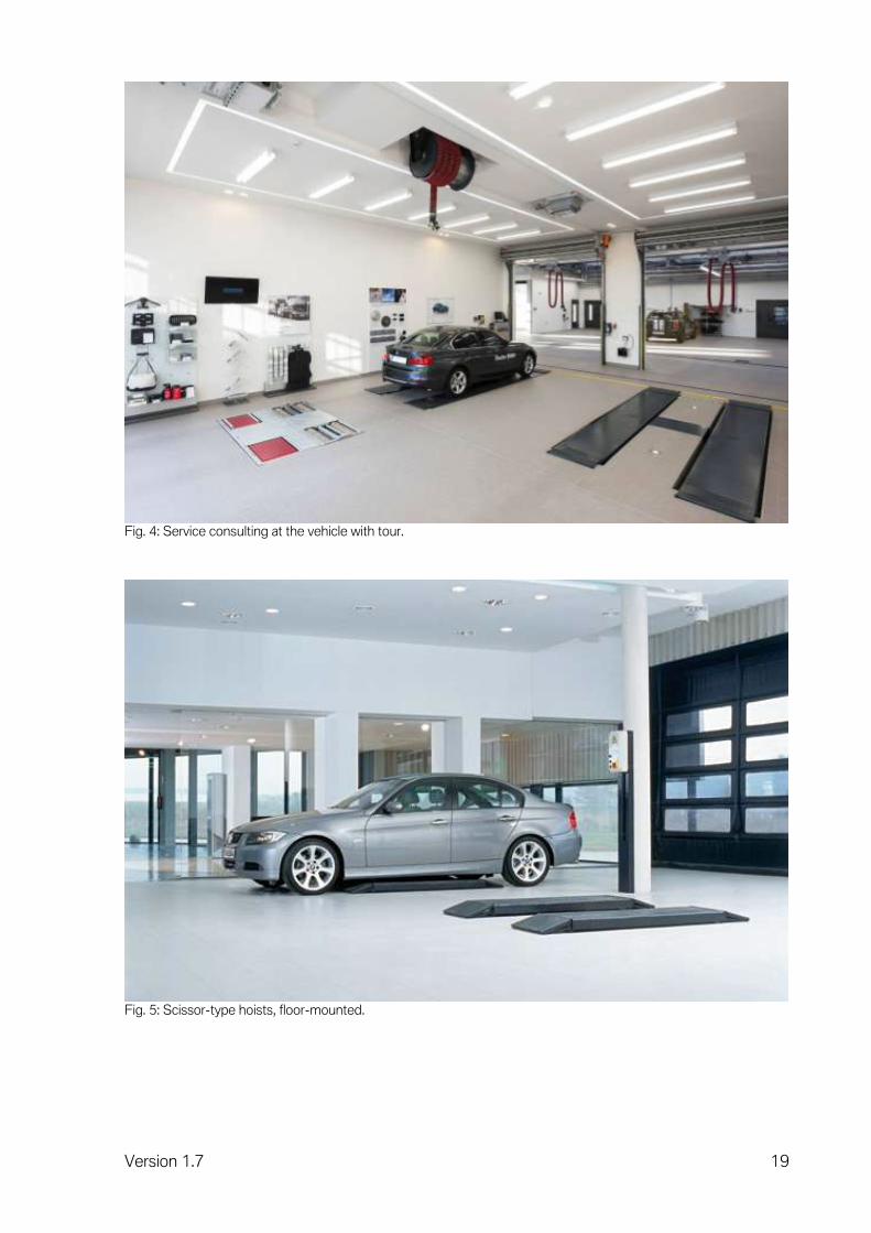
Fig. 4: Service consulting at the vehicle with tour. ..................................................... 19
Fig. 5: Scissor-type hoists, floor-mounted. ................................................................. 19
Fig. 6: Multifunctional hall............................................................................................. 24
Fig. 7: Wall-mounted equipment in multifunctional hall. ............................................ 24
Fig. 8: Compressor room with dual-piston compressor. ............................................ 29
Fig. 9: Information room. .............................................................................................. 36
Fig. 10: Collection point for damaged vehicles. .......................................................... 38
Fig. 11: Shelf system in warranty parts store. ............................................................. 40
Fig. 12: Warranty parts store. ....................................................................................... 40
Fig. 13: Mechanical workshop with two-piston vehicle hoists. .................................. 44
Fig. 14: Mechanical workshop with two-post vehicle hoists. ..................................... 45
Fig. 15: Brake test stand in combination with shock absorber test stand ................ 52
Fig. 16: BMW KDS Beissbarth II. ................................................................................. 55
Fig. 17: BMW KDS New Generation. .......................................................................... 55
Fig. 18: Headlight adjustment bay. .............................................................................. 58
Fig. 19: Programming. .................................................................................................. 64
Fig. 20: Workshop cabinet for IT equipment at the workbay. .................................... 64
Fig. 21: Oil storage room.............................................................................................. 76
Fig. 22: Assembly and machinery room. ..................................................................... 78
Fig. 23: Modular cupboard system with vertical drawer. ............................................ 80
Fig. 24: Painting and drying booth. .............................................................................. 87
Fig. 25: Painting and drying booths with additional drying booths in the longitudinal direction and assemblies installed above them. ......................................................... 90
Fig. 26: Empty box in enclosed pit. ............................................................................. 96
Fig. 27: Floor view of underfloor hoist. ...................................................................... 106
Fig. 28: Ceiling view of underfloor hoist. ................................................................... 106
Fig. 29: Underfloor hoist for mechanical repairs. ..................................................... 107
Fig. 30: Finished pit before installation of the test benches. ................................... 113
Fig. 31: Installed test benches (brake and shock absorber test stand). .................. 114
Fig. 32: Scissors-type lifting platform. ....................................................................... 114
Fig. 33: Paint preparation bays. ................................................................................. 127
Fig. 34: Suction rail with hose and exhaust socket. .................................................. 131
Fig 35: Suction rail with hose and exhaust socket. .................................................. 131

Version 1.7 9
Glossary.
A AIII Classification of water-polluting fluids ACC Active Cruise Control Ampere (A) Unit of electrical current strength AU Statutory emissions test (Germany)
B bar Unit of pressure
C Cat6 Classification of network cables to EN 50288 Celsius (C) Unit of temperature
D Dätwyler Unipatch modular S2/8 Product name for network outlets Diagnostic head Gateway for data transfer DIN Deutsches Institut für Normung (German Institute
for Standardisation) DN Nominal diameter
E EN European Standard
F Feet (ft) Unit of length. One foot is equivalent to 30.48 cm
G GT-1 Group Tester 1
H Hertz (Hz) Physical unit of frequency
I ICOM IEC IMIB
Integrated Communication Optical Module International Electrotechnical Commission Integrated Measurement Interface Box
ISID ISSS ISAP IT
Integrated Service Information Display Integrated Software Service Station Integrated Service Access Point Information Technology

Version 1.7 10
K KDS Kilopond (kp) Kilowatt (kW)
Kinematic diagnostic system Unit of weight force Unit of power
L LAN Local area network Litre (l) Unit of capacity lux Unit of illuminance
N NEMA National Electrical Manufacturers Association
O OPS Optical programming system OPPS Optical testing and programming system
P PC Personal computer PVC Polyvinyl chloride for flooring
Q Quante RJ 45 Modular Qmax Product name for network outlets
S SEG Headlight adjustment device Sectional gate Gate with rotatable sections ST Special tool
V VOC Volatile organic compounds Volt (V) Unit of electrical tension

Version 1.7 11
Explanation of symbols.
Diagram 1: Explanation of symbols, German
Diagram 2: Explanation of symbols, English
Version 1.7 12
1 Introduction.
Foreword on planning principles. The investment in the service area of a car dealership or service shop represents a significant portion of its overall outlay. In both new and converted buildings, planning mistakes can permanently undermine the profitability of service operations and customer satisfaction. Mistakes can arise if there is insufficient coordination between the vehicles to be serviced, the service processes, the workshop equipment and the way the floor, walls and ceiling of the workshop hall are laid out. The task of workshop planning is to prevent such mistakes and create an optimum basis. This document explains the basic principles that apply when planning workshops for motor vehicle maintenance work by BMW Group Service. All aspects of how to configure a needs-based motor vehicle workshop are described systematically and in detail. The location, size, technical equipment and building interfaces of all the customary functional units are shown. BMW Group vehicles and workshop equipment that is specific to the BMW Group serve as the basis for the design of the functional areas and individual workplaces. This workshop planning manual will enable building owners, workshop planners, architects, engineering services planners and stress analysts to make use of BMW Service Workshop Planning's findings from the outset. Details can be called up or entire functional units designed according to requirements. Applying these planning principles systematically will go a long way towards promoting the smooth interaction of BMW Group vehicle and Service technology in everyday workshop situations. Last but not least, the occupational safety and ergonomic aspects of planning play a key role in motivating Service personnel and encouraging them to perform well. These planning principles do not cover country-specific factors (such as the climate, rules governing the execution of buildings, directives, safety specifications). Any such differences are to be taken into account by the local planners. The dimensions of the workbays and ancillary rooms discussed below are for a small Service establishment of the BMW Group and should therefore be fundamentally regarded as the minimum requirements. All data and dimensions contained in the workshop planning manual are correct and valid at the time of publication. However, the latest plans should always be requested from the manufacturer before starting detailed planning. The workshop planning manual will be updated on an ongoing basis. The latest version is always binding.
Version 1.7 13
2 General requirements for the workshop area.
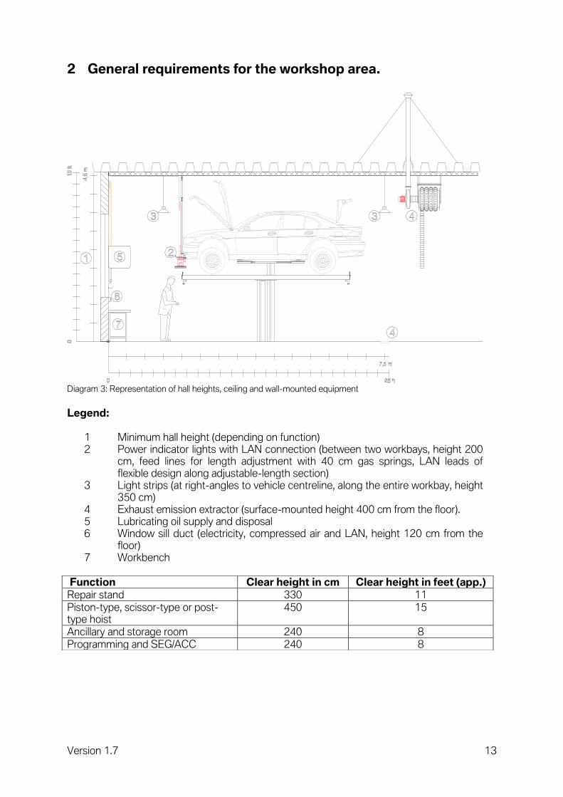
Diagram 3: Representation of hall heights, ceiling and wall-mounted equipment
Legend:
1 Minimum hall height (depending on function) 2 Power indicator lights with LAN connection (between two workbays, height 200
cm, feed lines for length adjustment with 40 cm gas springs, LAN leads of flexible design along adjustable-length section)
3 Light strips (at right-angles to vehicle centreline, along the entire workbay, height 350 cm)
4 Exhaust emission extractor (surface-mounted height 400 cm from the floor). 5 Lubricating oil supply and disposal 6 Window sill duct (electricity, compressed air and LAN, height 120 cm from the
floor) 7 Workbench
Function Clear height in cm Clear height in feet (app.)
Repair stand 330 11
Piston-type, scissor-type or post-type hoist
450 15
Ancillary and storage room 240 8
Programming and SEG/ACC 240 8

Version 1.7 14
All dimensions are clear dimensions incl. all installations (ventilation, heating, power, sanitation, etc.). The workshop floor must be able to withstand a pressure of 150 N/mm². A straightening bench incl. accessories and the vehicle add up to more than 11.000 pounds. Distributed over three rollers, this results in forces in excess of 57 N/mm². Therefore, it is recommended to have a full brick floor laid with the vibration process. The load assumption for a workshop floor is at least 10 KN/m². The strength category of the concrete floor for vehicle hoist workbays should be C25/30. Technical equipment:
Power indicator lights Unit
Voltage V 240/110, 400/440
Frequency Hz 50/60
Compressed air mm Inner diameter at least 8
Network outlets Dätwyler Unipatch modular S2/8 (at least Cat6) Quante RJ 45 Modular Qmax (at least Cat6)
Lighting Unit
Mechanical workshop lux 800
Service advice lux 800
Body lux 800
Painting area lux 1000
Programming area lux 500
Units compartment (Unit repair)
lux 500
Ancillary rooms lux 300
If required, install additional light strips along vehicle's centreline outside the vehicle's contours (incl. with doors open). Roof passages: Required for exhaust emission extractors, for painting booths and for welding smoke and grinding dust extractors.
Planning procedure Responsible
Defining roof passages Workshop service
Defining size Workshop service
Defining exact location Client
Execution procedure Responsible
Preparing the roof opening Client
Preparing the necessary anchor points Client
Defining the minimum height of extractor pipes Client
Preparing the extractor pipe with roof collar and deflector hood
Workshop service
Preparing the anchor cables Workshop service
Roof seal Client

Version 1.7 15
Fig. 1: Wall-mounted equipment.
Fig. 2: Ceiling-mounted equipment.

Version 1.7 16
3 Space concept.
3.1 Space concept requirements.
3.1.1 Service consultant at the vehicle.
Workbay for Service advice at the vehicle. Ideal for diagnosis during checking-in and visual inspection in the customer's presence, to determine the extent of work required. 90% of the required servicing is identified during the Service advice. During a detailed customer consultation, approx. 30 minutes of working time + approx. € 50 parts turnover can also be generated*. The Service advice must be directly accessible from the reception office and have a direct route to the showroom. The Service advice at the vehicle can also be implemented as a tour with direct access to the workshop. An underfloor hoist with tracks and wheel alignment hoist is recommended as a vehicle hoist, in order to check the wheel play and steering with the customer. In Service advice a brake test stand or a headlight adjustment device can also be considered.
Diagram 4: Representation of workbay for Service consulting.
*(Quelle = http://www.atr.de/uploads/media/blinklicht_3-2008.pdf).

Version 1.7 17
Diagram 5: Representation of workbay for Service consulting with brake-tester and headlight adjustment.
Legend:
1 Drive-on piston-type hoist flush with floor and wheel alignment hoist. 2 Control unit for hoist. 3 Energy supply. 4 Floor lights. 5 Exhaust emission extractor (surface-mounted). 6 Drainage channel. 7 Sectional gate (width 350 cm, height 300 cm). 8 Tyre inflator. 9 Hand basin. 10 Brake tester with display. 11 Headlight adjustment device/ACC adjustment device.
Room dimensions in cm in feet (approx.)
Length, width, height 1000, 500, 450 33, 16, 15
Technical equipment
Unit
Power sockets V/Hz 220/50 or 110/60
Network outlets Dätwyler Unipatch modular S2/8 (at least Cat6) Quante RJ 45 Modular Qmax (at least Cat6)
Compressed air bar 8

Version 1.7 18
Note. Before construction work starts, it is essential to check the various detailed specifications in the manufacturers' installation instructions and foundation plans. The current national specifications are to be observed when choosing the installation location. We recommend the installation of mirrors so that the entire surrounding area remains in view when the hoist is being lowered. Markings and possibly also warning signals should also be envisaged (accident prevention).
Fig. 3: Drive-on piston-type hoist flush with floor.
Version 1.7 19
Fig. 4: Service consulting at the vehicle with tour.
Fig. 5: Scissor-type hoists, floor-mounted.

Version 1.7 20
3.1.2 Portal car wash.
Separate hall for vehicle body washing. Also suitable for underbody washing with appropriate accessories. Self-service portal car wash versions operated by the customer must comply with special legislation (e.g. supervising personnel). As a rule, the car is washed before the handover to service, in order to detect any paint damage in good time. The washing time is about 10 min/car. A portal car wash would be a worthwhile investment if manual washing is too expensive or is slower than 6 cars/hour. Washing in a portal car wash uses less water than washing by hand. Conveyor car washes can cope with about 50 cars/hour, cost four times as much and are only worthwhile given sufficient capacity utilisation.
Diagram 6: Representation of portal car wash.

Version 1.7 21
Legend:
1 Multifunctional hall. 2 Piston-type hoist protected against water splashes and surges. 3 Control unit for hoist. 4 Grid (length 600 cm, width 400 cm), covering entire floor area of hall if possible. 5 Ancillary room (length 500 cm, width 200 cm, height 240 cm). 6 High-pressure cleaners. 7 Shelves for cleaning materials. 8 Water treatment system. 9 Control unit for portal car wash. 10 Portal car wash. 11 Drainage channel. 12 Energy supply (2x).
- Water tap. - Power socket (240 V/50 Hz or 110 V/60 Hz). - Power socket (400 V/50 Hz or 240 V/60 Hz). - Permanent wiring (400 V/50Hz or 240 V/60 Hz). - Compressed air coupling.
13 Switch cabinets. 14 Sectional gate (width 400 cm, height 350 cm). 15 Hand basin.
Room dimensions in cm in feet (approx.)
Length, width, height 1000, 450, 450 32, 15, 15
Note. Before construction work starts, it is necessary to check the various detailed specifications in the manufacturers' installation instructions and foundation plans. To avoid a risk of slipping (e.g. formation of ice) at the entrance to the portal car wash, we recommend the use of surface grids.
Version 1.7 22
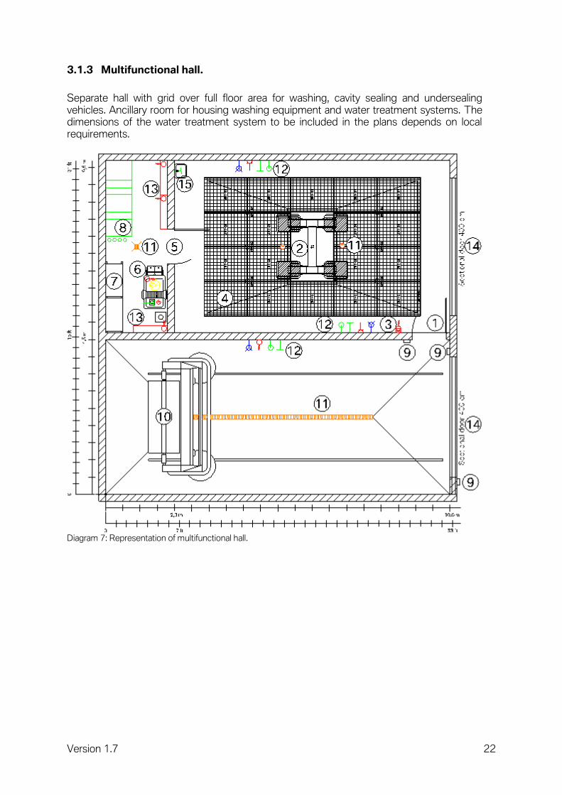
3.1.3 Multifunctional hall.
Separate hall with grid over full floor area for washing, cavity sealing and undersealing vehicles. Ancillary room for housing washing equipment and water treatment systems. The dimensions of the water treatment system to be included in the plans depends on local requirements.
Diagram 7: Representation of multifunctional hall.

Version 1.7 23
Legend:
1 Multifunctional hall. 2 Piston-type hoist protected against water splashes and surges. 3 Control unit for hoist. 4 Grid (length 600 cm, width 400 cm), covering entire floor area of hall if possible. 5 Ancillary room (length 500 cm, width 200 cm, height 240 cm). 6 High-pressure cleaners. 7 Shelves for cleaning materials. 8 Water treatment system. 9 Control unit for portal car wash. 10 Portal car wash. 11 Drainage channel. 12 Energy supply (2x).
- Water tap. - Power socket (240 V/50 Hz or 110 V/60 Hz). - Power socket (400 V/50 Hz or 240 V/60 Hz). - Permanent wiring (400 V/50Hz or 240 V/60 Hz). - Compressed air coupling.
13 Switch cabinets. 14 Sectional gate (width 400 cm, height 350 cm). 15 Hand basain.
Room dimensions in cm in feet (approx.)
Length, width, height 800, 500, 450 26, 16, 15
Note. A grid over the full floor area of the multifunctional hall is recommended for the following reasons:
Neat appearance of workshop.
Reduced risk of accidents and slipping.
Less cleaning work.
Simpler building work.
Lower installation costs.
No accumulated water on floor. To avoid a risk of slipping (e.g. formation of ice) at the entrance to the multifunctional hall, we recommend the use of surface grids.
Version 1.7 24
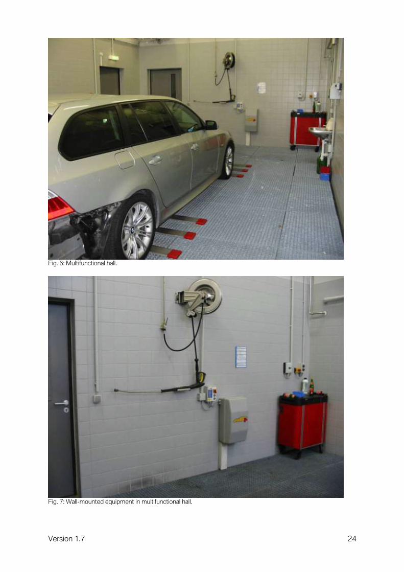
Fig. 6: Multifunctional hall.
Fig. 7: Wall-mounted equipment in multifunctional hall.

Version 1.7 25
3.1.4 Vehicle preparation.
Workbays for preparing new vehicles, used cars and vehicles before or after a workshop visit. The hall should be located in close proximity to the car wash or multifunctional hall, so that freshly washed vehicles can be prepared directly. The workbay for vehicle preparation should not be in the workshop, in order to avoid contamination at the vehicle. Regardless of the weather conditions, there must be a connection to the vehicle showroom area and to the new vehicle delivery from the workbay for vehicle preparation. This can be effected in the building, or outside with weather protection (roof). With a washing time of 10 minutes/vehicle in a portal car wash and subsequent preparation time of approx. 20 minutes/vehicle, 2 to 3 workbays suffice for vehicle preparation, in order to satisfy the continuity of a portal car wash. At least 1 workbay for vehicle preparation is required if using washing halls with hand basins.
Diagram 8: Schematic diagram of workbay for vehicle preparation after a portal car wash.
Legend:
1 Workbay for vehicle preparation. 2 Cabinets for cleaning agents. 3 Vacuum cleaner. 4 Hand basin. 5 Power supply.
- 2x sockets (240 V/50 Hz or 110 V/60 Hz). 6 Multifunctional hall. 7 Portal car wash. 8 Drainage channel.

Version 1.7 26
Room dimensions in cm in feet (approx.)
Length, width, height 700, 450, 250 23,15,8
Technical equipment
Unit
Power sockets V/Hz 240/50 or 110/60
Lighting lux 900 – 1.000
Note. Room lighting with 900 to 1,000 lux is recommended, in order to be able to better identify possible surface damage on the vehicle during the preparation of new vehicles. The floor can be designed as a concrete surface, chemically compacted, R11, anti-slip.

Version 1.7 27
3.1.5 Compressor room with compressed air system.
Room for installation of the compressed air compressor. The minimum pressure in the workshop must be at least 8 bar at the tapping point. The maximum compressed air pressure should be 10 bar. The volumetric flow is dependent on the size of the company and the consumers. An exact calculation is therefore necessary. Compressor types: Screw or piston-type compressor (depending on consumption). Plan in a cooling air supply and air outlet aperture. The air inlet aperture must be dimensioned to reflect the air intake rate. The thermal output corresponds approximately to the wattage of the compressor. The room temperature must be between ±0 and +35 degrees Celsius. The room illumination requires min. 300 lux.
Diagram 9: Representation of compressor room with compressed air system with dual-piston compressor.
Legend:
1 Piston-type compressor with pressure reservoir. 2 Refrigeration dryer. 3 Oil and water separator with connection to sewer system. 4 Compressed air line.

Version 1.7 28
Diagram 10: Compressor room with compressed air system with screw-type compressor.
Legend:
1 Screw-type compressor. 2 Pressure reservoir. 3 Refrigeration dryer. 4 Oil and water separator with connection to sewer system. 5 Compressed air line.
Room dimensions in cm in feet (approx.)
Length, width, height 300, 300, 250 10, 10, 8
Technical equipment
Unit
Permanent wiring V/Hz 400/50 or 220/60
Permanent wiring V/Hz 240/50 or 110/60
Lighting lux 300
Note. Door opening at least 1.2 m wide. Plan in soundproofing measures. In the room a distance of at least 60 cm to the system should be taken into consideration from two sides for servicing.

Version 1.7 29
Fig. 8: Compressor room with dual-piston compressor.
Compressor. Piston or screw-type compressors are suitable for workshop use. Piston-type compressors are suitable up to a delivery rate of 1000 litres/min. Screw-type compressors are more appropriate for higher delivery rates. The precise air consumption rate is determined by adding together all compressed air consumers, taking into account how long the individual devices are used for. The critical factor determining the compressor's size is the delivery rate, not the air intake rate. Unlike screw-type compressors, piston-type compressors are not suitable for continuous use. The ideal compressor system consists of two compressors each achieving at least 80 % of the required delivery rate, operating alternately. Such an arrangement means that the workshop can continue to function without interruptions even if one compressor is faulty or if maintenance work is being carried out. Pressure reservoir. The pressure reservoir prevents the compressors from cutting in when consumers prompt minor pressure fluctuations. Its size should correspond roughly to one minute's air consumption. The compressed air cools down in the pressure reservoir, causing some of the moisture in the compressed air to condense and be precipitated. This condensate must be drained off automatically or manually at regular intervals (depending on the levels occurring). The compressed air lines should not be included in the reservoir capacity.

Version 1.7 30
Refrigeration dryer. The moisture present in the compressed air can damage pneumatic equipment. Moisture in compressed air also causes defects during the painting process. The task of the refrigeration dryer is to cool down the compressed air sufficiently for virtually all the moisture in it to condense and be precipitated. It is important to dimension the refrigeration dryer correctly. The compressed air used in a paint shop should always be passed through a refrigeration dryer. Oil and water separator . The compressed air also contains small amounts of lubricating oil from the compressor as well as water and suspended particles. For environmental reasons, the lubricating oil should be removed from the water before it is discharged into the sewer network. This task is performed by the oil and water separator. All the condensate arising (from the pressure reservoir and refrigeration dryer) should be passed through the oil and water separator. Fine filter. The fine filter traps the suspended particles in the compressed air. These suspended particles cause defects in the vehicle painting process. This filter should be present at least before the tapping point for painting air. Compressed air line. Takes the form of a ring main (ND 35 mm) with gate valves for shutting down the compressed air ring main temporarily for maintenance and repair work while workshop operations continue. The ring main should be laid with a slight incline and have a vertical pipe with drain tap at its lowest point. This incline means that any condensate will collect in the vertical section of pipe and can then be drained off at the tap. The stub pipes (ND 10) should connect with the top side of the ring main and lead to the workbay after a 180 degree elbow. By being connected with the ring main from above, no condensate can enter the stub pipe. Where possible, the pipe material should have smooth inner walls made from any type of material,however no products containing silicone. Stainless steel pipes are recommended. Do not use hemp seals when assembling the entire pipe network due to the tendency of this type of connection to dry out and thus cause leaks. Divide up larger workshops into several ring mains (mechanical workshop, body shop and paint shop), each with a separate supply from the compressor system. Comply with the pressure vessel ordinance ("Directive 87/404/EEC for simple pressure vessels"): max. pressure content product (pressure times volume; P*V) must not exceed 10,000 bar*litres. Service unit. The service units are located at the workbay end of the stub pipes and comprise a pressure regulator, lubricator, water separator and quick connectors. The pressure regulator can be used to restrict the compressed air supply e.g. for painting. The lubricator blends oil into the compressed air. This is only required for lubricating the gears in the pneumatic equipment. Blending in oil improves the functioning and operating life of the pneumatic equipment. The water separator is not necessary if the compressed air is passed through a sufficiently large refrigeration dryer. The quick connectors are fitted between the individual devices so that the appropriate amount of compressed air can be used as required. Use only quick connectors that first bleed only the compressed air line when operated, and then release the quick connector as a second step. This prevents the line from being pressurised suddenly and in an uncontrolled way, placing the operator at risk of injury.

Version 1.7 31
Diagram 11: Schematic compressed air ring main.
Legend:
1 Compressor system. 2 Gate valves (ball valves).

Version 1.7 32
Diagram 12: Wall view of compressed air line network.
Legend:
1 Ring main run at incline. 2 Stub pipe with stop valve. 3 Service unit. 4 Window sill duct for electricity, compressed air and data lines and sockets. 5 Water drain tap.

Version 1.7 33
3.1.6 Workshop Supervisor's office.
This room is the Workshop Supervisor's regular place of work. It is equipped as an office, taking account of the workshop environment (PVC floor and easy-to-clean surfaces).
Diagram 13: Representation of Supervisor's office.
Legend:
1 Network-compatible PC. 2 Filing cabinets. 3 Chair and desk.

Version 1.7 34
Room dimensions in cm in feet (approx.)
Length, width, height 300, 300, 240 10, 10, 8
Technical equipment
Unit
Power sockets V/Hz 240/50 or 110/60
Permanent wiring V/Hz 240/50 or 110/60
Network outlets Dätwyler Unipatch modular S2/8 (at least Cat6) Quante RJ 45 Modular Qmax (at least Cat6)
Note. This room should ideally be located at a central point in the workshop. In smaller establishments, it can be combined with Service Reception. The room illumination must be min. 300 lux.

Version 1.7 35
3.1.7 Information room.
This room contains the entire range of workshop literature, for consultation by the workshop personnel. There must be a phone and a fax machine. It is equipped as an office, taking account of the workshop environment (PVC floor and easy-to-clean surfaces). A window to provide visual contact between the information room and workshop area is advisable.
Diagram 14: Representation of information room.
Legend:
1 ISSS programming station. 2 Network-compatible PC. 3 Filing cabinets. 4 Chair and desk.

Version 1.7 36
Room dimensions in cm in feet (approx.)
Length, width, height 250, 300, 240 8, 10, 8
Technical equipment
Unit
Power sockets V/Hz 240/50 or 110/60
Network outlets Dätwyler Unipatch modular S2/8 (at least Cat6) Quante RJ 45 Modular Qmax (at least Cat6)
Note. This room should ideally be located at a central point in the workshop. The room illumination must be min. 500 lux.
Fig. 9: Information room.

Version 1.7 37
3.1.8 Collection point for residual materials and accident vehicles.
For the proper storage of residual materials and accident vehicles. Store residual materials and damaged vehicles in such a way that no polluting substances can leak out. Damaged vehicles in addition need to be stored such that the theft of parts is prevented and the vehicles' value is not impaired by weathering (rain, snow etc.).
Diagram 15: Representation of collection point for residual materials and damaged vehicles.
Legend:
1 Lattice roll-up gate. 2 Mesh fence. 3 Residual materials.
Room dimensions in cm in feet (approx.)
Length, width, height 600, 1000, 240 20, 33, 8

Version 1.7 38
Form. Liquid-tight floor, lockable, with weather protection. Note. This area should be easily accessible from the workshop, but may be structurally separated from the building. Access for damaged vehicles should be straightforward. It must be possible for a waste disposal contractor to collect residual materials. The room illumination must be min. 300 lux.
Fig. 10: Collection point for damaged vehicles.

Version 1.7 39
3.1.9 Warranty parts store.
For storing removed parts for subsequent inspection or returning in settlement of warranty claims.
Diagram 16: Representation of warranty parts store.
Room dimensions in cm in feet (approx.)
Length, width, height 300, 250, 240 10, 8, 8
Note. Lockable room with 1.2 m access door. The conditions for storage rooms apply. The room illumination must be min. 300 lux.

Version 1.7 40
Fig. 11: Shelf system in warranty parts store.
Fig. 12: Warranty parts store.

Version 1.7 41
3.2 Space concept for mechanical service.
3.2.1 Workbay for mechanical repairs.
General workbay for maintenance and repair work. A combination with other functions (headlight adjustment bay, ACC adjustment bay, etc.) is possible. Basically should be planned at least one battery charger for two workbays.
Diagram 17: Representation of workbays for mechanical repairs.

Version 1.7 42
Legend:
1 Fresh oil supply, old oil disposal (at central point between 4 workbays). 2 Workbench with vice. 3 Mobile tool trolley with set of tools. 4 Power supply.
- Hoist actuation. 5 Hoist (piston-type, scissor-type or post-type hoist). 6 Exhaust emission extractor (surface-mounted). 7 Power indicator lights with LAN connection (in each case between two workbays). 8 Power supply.
- Socket (240 V/50 Hz or 110 V/60 Hz). - Compressed air plug-in coupling . - LAN connection (2x).
Room dimensions in cm in feet (approx.)
Length, width, height 700, 360/380, 450 23, 12/13, 15
Note. The workbay width varies depending on the type of hoist. Where underfloor hoists are used, a width of 360 cm (approx. 12 feet) is needed, and a width of 380 cm (approx. 13 feet) for surface-mounted hoists. For workbays with vehicle hoists, which are located directly at a wall, an additional distance of 30 cm (12 inches) from the workbay to the wall must be observed. The ceiling anchor points for the power indicator lights must be configured with a minimum retaining force of 2 kN. The compressed air line is routed between 240V –/ and the LAN connection.

Version 1.7 43
3.2.2 Workbay for mechanical repairs (pit solution).
General workbay for maintenance and repair work, as a garage workbay (pit solution).
Diagram 18: Representation of workbays for mechanical repairs (pit solution).
Diagram 19: Representation of workbays for mechanical repairs (pit solution).
Version 1.7 44
Legend:
1 Fresh oil supply, old oil disposal (at central point between 4 workbays). 2 Workbench with vice. 3 Mobile tool trolley with set of tools. 4 Energy supply.
- Hoist controls. - Power socket (240 V/50 Hz or 110 V/60 Hz). - Compressed air coupling. - LAN connection (2x).
5 Hoist (piston-type, scissor-type or post-type hoist). 6 Exhaust emission extractor (surface-mounted). 7 Power indicator lights with LAN connection (in each case between two workbays). 8 Sectional gate 9,8 feet.
Raumdimensionen in cm in feet (ca.)
Länge, Breite, Höhe 800, 400, 450 26, 13, 15
Note. The sectional gate must run directly under the ceiling at a height of 14,8 feet when open. If an exhaust emission extractor above the floor (hose reel) is used, it must either be attached to the wall or the ceiling at a sufficient distance from the sectional gate.
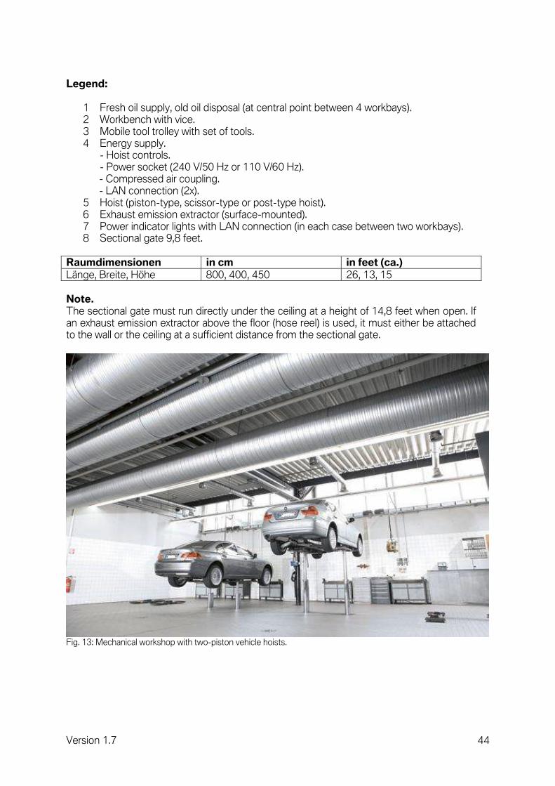
Fig. 13: Mechanical workshop with two-piston vehicle hoists.

Version 1.7 45
Fig. 14: Mechanical workshop with two-post vehicle hoists.

Version 1.7 46
3.2.3 Inspection line.
Separate hall for inspection of the entire vehicle.
Diagram 20: Representation of inspection line (top view).
Diagram 21: Representation of inspection line (side view).

Version 1.7 47
Legend:
1 Hoist. 2 Shock absorber test stand. 3 Brake test stand. 4 Display for shock absorber and brake test stand. 5 Power indicator lights with LAN connection. 6 Hoist controls. 7 Headlight adjustment device/ACC adjustment device. 8 Tyre inflator. 9 Workbenches. 10 Sectional gate 3.5 x 3.0 m (side view). 11 Energy supply.
- Power socket (220 V/50 Hz or 110 V/60 Hz). - LAN connection. - Compressed air coupling.
12 Exhaust emission extractor (suction rail). 13 Drainage channel. 14 Light strips (side view).
Room dimensions in cm in feet (approx.)
Length, width, height 1150, 450, 450 38, 15, 15
Note. Before construction work starts, it is necessary to check the various detailed specifications in the manufacturers' installation instructions and foundation plans. The specifications and directives of the industrial accident insurers and the requirements of the Workplaces Ordinance must be observed when choosing the location. Siting outdoors is not recommended as use will be severely weather-dependent. When using a brake test stand, ensure that the vehicle hoist is installed in front of the brake test stand and is even with the floor level, and not higher than the brake test stand (+ 8 cm/3 inches).

Version 1.7 48
3.2.4 Test benches.
The various test benches are explained in the following chapters. The following floor conditions are to be observed in siting these test benches. A level workshop floor before and after the test benches, across the maximum wheelbase of all models, is recommended. The maximum permitted variation in height of the workshop floor before the test benches may not exceed 12% over a maximum length of 75 cm. This means that the maximum height difference is 8 cm/ 3 inches.
Diagram 22: Side view of test benches with height difference.
Version 1.7 49
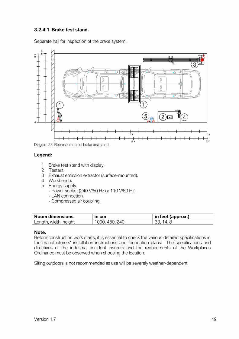
3.2.4.1 Brake test stand.
Separate hall for inspection of the brake system.
Diagram 23: Representation of brake test stand.
Legend:
1 Brake test stand with display. 2 Testers. 3 Exhaust emission extractor (surface-mounted). 4 Workbench. 5 Energy supply.
- Power socket (240 V/50 Hz or 110 V/60 Hz). - LAN connection. - Compressed air coupling.
Room dimensions in cm in feet (approx.)
Length, width, height 1000, 450, 240 33, 14, 8
Note. Before construction work starts, it is essential to check the various detailed specifications in the manufacturers' installation instructions and foundation plans. The specifications and directives of the industrial accident insurers and the requirements of the Workplaces Ordinance must be observed when choosing the location. Siting outdoors is not recommended as use will be severely weather-dependent.

Version 1.7 50
3.2.4.2 Shock absorber test stand.
Separate hall for inspecting the vehicle suspension and shock absorbers with rubber mounts in an installed condition. Combinations with other test bays (e.g. brake tester) are possible.
Diagram 24: Representation of shock absorber test stand.
Legend:
1 Shock absorber test stand with display. 2 Energy supply.
- Power socket (240 V/50 Hz or 110 V/60 Hz). - Permanent wiring (400 V/50 Hz or 220 V/60 Hz). - Compressed air coupling.
3 Exhaust emission extractor (surface-mounted).
Room dimensions in cm in feet (approx.)
Length, width, height 1000, 400, 240 33, 13, 8
Note. Before construction work starts, it is necessary to check the various detailed specifications in the manufacturers' installation instructions and foundation plans.

Version 1.7 51
3.2.4.3 Brake and shock absorber test stand.
Separate hall for inspecting the brake system, vehicle suspension and shock absorbers with rubber mounts in an installed condition.
Diagram 25: Representation of brake and shock absorber test stand.
Legend:
1 Brake and shock absorber test stand with display. 2 Testers. 3 Exhaust emission extractor (surface-mounted). 4 Workbench. 5 Energy supply.
- Power socket (240 V/50 Hz or 110 V/60 Hz). - LAN connection. - Compressed air coupling.
Room dimensions in cm in feet (approx.)
Length, width, height 1000, 450, 240 33, 14, 8
Note. Before construction work starts, it is necessary to check the various detailed specifications in the manufacturers' installation instructions and foundation plans. The brake tester should be installed before the shock absorber tester, in the direction of access. If the brakes are tested to the point of locking (in the case of parking brake), the vehicle will move backwards out of the brake tester and would otherwise come to rest on the shock absorber tester's plates. If the shock absorber tester were in the automatic mode, it would start up unintentionally, causing a variety of problems.

Version 1.7 52
Fig. 15: Brake test stand in combination with shock absorber test stand

Version 1.7 53
3.2.5 Wheel alignment workbay.
Workbay for wheel alignment with BMW KDS. Combinations with other workbays are possible.
Diagram 26: Representation of workbay for wheel alignment.
Legend:
1 BMW KDS trolley. 2 BMW KDS New Generation with camera technology. 3 Tool trolley. 4 Four-post, scissor-type of piston-type hoist. 5 Exhaust emission extractor (surface-mounted). 6 Power indicator lights with LAN connection. 7 Energy supply.
- Compressed air. - Power socket 240 V/50 Hz. - LAN connection.
Room dimensions in cm in feet (approx.)
Length, width, height 700, 450, 450 23, 15, 15

Version 1.7 54
Note. Wheel alignment compatible hoist necessary.
Hoist Requirement Dimension
All hoists Effective length of track At least 4,400 mm
Effective width of (fixed) track At least 630 mm
Space betw. tracks 900-950 mm
Diagram 27: Representation of workbay for wheel alignment with BMW KDS Hunter II (side view).

Version 1.7 55
Fig. 16: BMW KDS Beissbarth II.
Fig. 17: BMW KDS New Generation.

Version 1.7 56
3.2.6 Combined workbays.
3.2.6.1 Headlight adjustment bay.
In order to be able to guarantee high measuring and setting accuracy of the headlight adjustment, it is necessary to observe defined preconditions at the headlight adjustment area. The evenness and the downhill gradient of the headlight adjustment area must be determined using measurements and taken into consideration when erecting the workbay. A workbay with the max. floor tolerances defined below is required for headlight adjustment.
Diagram 28: Representation of workbay for headlight adjustment (top view).
Diagram 29: Representation of workbay for headlight adjustment (side view).

Version 1.7 57
Diagram 30: Representation of workbay for headlight adjustment (rear view).
Diagram 31: Schematic diagram of workbay for headlight adjustment (side view/downhill gradient).
Legend:
1 Headlight adjustment device with floor rails. 2 Tyre inflator. 3 Energy supply.
- Power socket (240 V/50 Hz or 110 V/60 Hz). - Compressed air coupling. - LAN connection.
4 Exhaust emission extractor (surface-mounted). 5 Light strip (side view).
Room dimensions in cm in feet (approx.)
Length, width, height 700, 360, 240 23, 12, 8

Version 1.7 58
1. The distance between the headlight adjustment device and the front edge of the vehicle is defined by the equipment manufacturer (approx. 30 cm).
2. The distance between the wall and headlight adjustment device should be min. 80 cm.
3. A tolerance of 4 mm is allowed where the workbay is even in a longitudinal and transverse direction. (see Fig. 30).
4. The permissible downhill gradient in a longitudinal and transverse direction of a headlight adjustment area can be max. 15 mm per metre. This corresponds to a downhill gradient of 1.5%. (see Fig. 31).
Note. For track-guided adjustment devices, during the assembly of the tracks ensure that the front guide rail and the rear track are mounted parallel to each other. Fault-free running of the headlight adjustment device is thus guaranteed. We recommend combining this workplace with the ACC adjustment bay.
Fig. 18: Headlight adjustment bay.

Version 1.7 59
3.2.6.2 ACC adjustment bay.
A workbay with the max. floor tolerances defined below is required for the Active Cruise Control (ACC) system.
Diagram 32: Representation of workbay for ACC adjustment (top view).
Diagram 33: Representation of workbay for ACC adjustment (side view).

Version 1.7 60
Diagram 34: Representation of workbay for ACC adjustment (front view).
Legend:
1 ACC adjustment device with floor rail. 2 Tyre inflator. 3 Energy supply.
- Power socket (240 V/50 Hz or 110 V/60 Hz). - Compressed air coupling.
4 Exhaust emission extractor (surface-mounted). 5 Light strip (side view).
Room dimensions in cm in feet (approx.)
Length, width, height 700, 360, 240 23, 12, 8
1. Distance between wall and floor rail at least 80 cm. 2. Distance between ACC adjustment device and front edge of vehicle
(120 cm +/- 5 cm). 3. Maximum floor unevenness
under ACC adjustment device (1 mm). under vehicle (10 mm).
4. Max. angle of area under vehicle. 5. Downward sloping area max. 3 degrees. 6. Upward sloping area max. 1 degree. 7. Within the area under vehicle, maximum height differences less than 10 mm.
Note. We recommend combining this workplace with the headlight adjustment bay.

Version 1.7 61
3.2.6.3 Combined workbay for headlight and ACC adjustment.
A workbay with the max. floor tolerances defined below is required for adjustment of the main headlights and the Active Cruise Control (ACC) system. The maximum requirements for the individual workbays may not simply be combined.
Diagram 35: Representation of workbay for headlight/ACC adjustment (top view).
Diagram 36: Representation of workbay for headlight/ACC adjustment (side view).

Version 1.7 62
Diagram 37: Representation of workbay for headlight/ACC adjustment (rear view).
Legend:
1 Headlight adjustment device with floor rails. 2 Tyre inflator. 3 Energy supply.
- Power socket (240 V/50 Hz or 110 V/60 Hz). - Compressed air coupling. - LAN connection.
4 Exhaust emission extractor (surface-mounted). 5 Light strip (side view). 6 ACC adjustment device.
Room dimensions in cm in feet (approx.)
Length, width, height 700, 360, 240 23, 12, 8
1. Distance between headlight adjustment device and vehicle's
front edge 30 cm. 2. Distance between wall and headlight adjustment device at least 80 cm. 3. Distance between ACC adjustment device and wall at least 60 cm. 4. Note max. tolerances for floor (see views).
Note. The ACC adjustment device is only compatible with the track-mounted BMW headlight adjustment device. Both devices use a track for the headlight adjustment device.

Version 1.7 63
3.2.7 Programming workbay.
Workbay for programming vehicles. These tasks can also be carried out in other workbays, but could then block them for several hours.
Diagram 38: Representation of workbay for programming.
Legend:
1 Energy supply. - Power sockets 240 V/110 V (3x). - LAN connection (2x), networked with the Software Service Station. - Compressed air coupling.
2 Battery charger. 3 Power indicator lights with LAN connection. 4 ISID incl. workshop trolley. 5 Exhaust emission extractor (surface-mounted).
Room dimensions in cm in feet (approx.)
Length, width, height 700, 300, 240 23, 10, 8
Note. Workbays must have weather protection and the ambient temperature may not fall below +10 degrees Celsius. The ISID is networked with the ISSS.

Version 1.7 64
Fig. 19: Programming.
Fig. 20: Workshop cabinet for IT equipment at the workbay.

Version 1.7 65
3.2.8 High-voltage workbay (BMW i). The scope of the workbay described here corresponds to a mechanical workbay. In order to be able to guarantee safe work at the high-voltage components of the BMW i vehicles, certain requirements of the workbays must be observed. Ideally, two workbays located in close proximity must be planned for the repair of BMW i vehicles. These workbays must be equipped with corresponding barriers (e.g. barrier tape). One workbay must be equipped with a suitable vehicle hoist (see "Requirements of vehicle hoists" in this chapter). The second workbay can be optionally equipped with a vehicle hoist. The high-voltage components are generally removed from the vehicle at one workbay and repaired at the second workbay. The following system and function checks, service and repair work on the electronics, mechanics and high-voltage components can be carried out at the high-voltage workbay.
System checks and work on the vehicle electrical system & high-voltage/traction (e.g. brake, chassis and suspension, interior equipment).
Exchange of high-voltage components.
Adaptation of the state of charge (SOC) of the new high-voltage battery modules to the existing modules.
Repair/Check of the high-voltage battery (at a separate workbay or in the Unit Repair Room).
Mechanical work and work on the 12 V vehicle electrical system. Taking into consideration suitable vehicle hoists (see "Requirements of vehicle hoists" in this chapter), there are no special requirements of the workbay for mechanical work (without removing assemblies) and work on the 12 V vehicle electrical system. Body work. All repair work on the body, both on CFRP (carbon fibre reinforced plastic) and aluminum components, is not carried out at the high-voltage workbay. This repair work is only carried out at body workbays with the necessary equipment such as explosion-proof vacuum cleaner (extra protection) and the carbon body tool. When choosing the BMW i body workbay, ensure that no flying sparks reach the carbon and aluminum components from other workbays. This is why the workbay should be positioned in a restricted area of the workshop or protected by corresponding partition walls. High-voltage charging option. If repair work is to be performed at the vehicle while the high-voltage battery is charging, it is imperative to observe the information in the corresponding repair instructions! The high-voltage battery can only be charged using a high-voltage charger. When choosing a suitable place for charging, bear in mind that a high-voltage battery may take several hours until it is fully charged. This is why a place should be selected which does not interfere with the workshop operation. Charging can be performed at conventional programming workbays, if there is a wall-mounted high-voltage charger. The high-voltage charger can have one or two connections (each 40 A) for charging. If high voltage is charged at a programming workbay, the number of programming workbays in a workshop must be supplemented accordingly.

Version 1.7 66
High-voltage storage. High-voltage batteries are not transported or stored. Only high-voltage modules can be transported. No high-voltage modules are stored in the dealer organisation. In the event of a repair, the high-voltage modules are ordered from the nearest supplier (RDC, CDC) and installed after arriving in the workshop. Disposal. In the case of faulty high-voltage batteries, a distinction is made between "transportable" and "non-transportable". A suitable qualified electrician on-site or Technical Support is informed in the case of non-transportable high-voltage batteries (identification through diagnosis query template). The electrician or Technical Support organises the transport. Non-transportable high-voltage batteries must be stored in a trough (acid-resistant, non-flammable, leak proof) and protected against weather influences, in order to prevent penetration of electrolyte in the soil. Non-transportable high-voltage batteries must be stored temporarily outside at a marked location (the distance to buildings, vehicles and other combustible materials is market-specific). The non-transportable high-voltage batteries remain there until they are collected by a professional authority.

Version 1.7 67
Diagram 39: Schematic diagram of high-voltage workbay.

Version 1.7 68
Legend:
1 Workbench with vice. 2 Mobile tool trolley with tool set. 3 Power supply.
Socket (240 V/50 Hz or 110 V/60 Hz).
Compressed air quick connector.
LAN connection (2x). 4 Vehicle hoist. 5 Energy module with LAN connection (between two workbays). 6 Mobile elevating platform with special fixture for high-voltage components. 7 A/C service device. 8 Charging/Discharging device for cell modules. 9 End of Service tester. 10 Barrier posts and barrier tape (Tensa barriers).
Room dimensions in cm in feet (approx.)
length, width, height 700, 380, 450 23, 12, 15
Note. Workbays for high-voltage components must be protected against weather conditions. It is also important to ensure that no flying sparks reach the high-voltage components from other workbays. This is why the workbays should be positioned in a restricted area of an existing workshop where possible. Requirements of vehicle hoists. All swivel arm vehicle hoists, which satisfy the BMW specifications, in 2-post or 2-piston version, are generally suitable for BMW i vehicles. Vehicle hoists with flat carriers are only suitable if the fixtures have longitudinal and transverse adjustment (X/Y adjustment) and the necessary dimensions are observed. Which dimensions for which type of vehicle hoist, suitable for which BMW i vehicle, can be found in the document "Workbay requirement for BMW i electric and hybrid cars", see SI No.: 00 42 13 (046) or: ASAP (Aftersales Assistance Portal) > Construction and installation advice.
> Workshop equipment. > Downloads.
For unobstructed positioning of the mobile elevating platform, these vehicle hoists cannot have any thresholds between the posts or pistons (see area shaded in red in Fig. 40).

Version 1.7 69
Diagramm 40: Darstellung Arbeitsbereich Hebebühne.
The minimum space requirement for the removal of the high-voltage batteries, the electric motor and the combustion engine under the raised vehicle is 140 cm x 340 cm (55.12 inches x 133.86 inches).
Diagramm 41: Schematic diagram of minimum space requirement for high-voltage battery, electric motor, REx, combustion engine (shaded in red).

Version 1.7 70
3.2.9 Emissions testing room and engine diagnosis workbay.
Separate hall for performing emissions testing and engine tuning. In view of the considerable noise and exhaust emissions generated, the specifications of the industrial accident insurers are to be complied with. It is of only limited suitability for use as a repair workbay.
Diagram 42: Representation of emissions testing room.
Legend:
1 Sectional gate (width 300 cm, height 300 cm). 2 Hoist. 3 Tool trolley. 4 Workbench with vice. 5 Energy supply.
- Power socket (240 V/50 Hz or 110 V/60 Hz). - LAN connection. - Compressed air coupling.
6 Control unit for hoist. 7 Emission tester. 8 Power indicator lights with LAN connection. 9 Exhaust emission extractor (surface-mounted or underfloor), higher-performance. 10 Drainage channel.
Room dimensions in cm in feet (approx.)
Length, width, height 800, 400, 450 26, 13, 15
Note. Before construction work starts, it is necessary to check the various detailed specifications in the manufacturers' installation instructions and foundation plans.

Version 1.7 71
3.2.10 High-security vehicle workbay. Workbay for maintenance and repair work on high-security vehicles.
Diagram 43: Schematic diagram of workbay for high-security vehicle repair.

Version 1.7 72
Legend:
1 Workbench with vice. 2 Tool trolley. 3 Vehicle hoist (5 t). 4 Energy module with LAN connection. 5 Exhaust emission extractor (surface-mounted). 6 Sectional gate 300 cm - 350 cm. 7 Safety door (only for authorised individuals). 8 Shelf or cabinet for storing tool. 9 Battery charger. 10 Power supply.
Socket (240 V/50 Hz or 110 V/60 Hz).
Compressed air quick connector.
LAN connection (2x).
Room dimensions in cm in feet (approx.)
length, width, height 800, 900, 450 26, 29, 15
Note. Before commencement of construction, the installation instructions and foundation plans of the manufacturer must be observed in the planning phase due to the different detailed versions. Repairs to high-security vehicles must be carried out in separate, lockable rooms of the workshop. The rooms are only accessible to authorised individuals. The rooms for high-security vehicles contain at least two workbays. One workbay must be equipped with a vehicle hoist (load capacity 5 t). The second workbay is used for the glass repair or also the closure of high-security vehicles before or after the repair. The wheel alignment (vehicle hoist with load capacity 5 t), as well as work at the tyre, can be carried out in the mechanical workshop. The wheel load capacity of the workshop floor, as well as the navigable areas (also grid), must be able to withstand a load of at least 1,200 kg.

Version 1.7 73
3.2.11 Rolls-Royce workbay.
General workbay for maintenance and repair work on Rolls-Royce cars. Basically, this workbay is equipped like a mechanical workbay for BMW cars. The differences are:
- Workbay dimensions 4.50 m x 8 m. - Hoists to be used (under floor/2-piston). - Driveway from 7 m to 8 m.
Diagram 44: Representation of workbay for Rolls-Royce cars.

Version 1.7 74
Legend:
1 Workbench with vice. 2 Tool trolley. 3 Power supply.
- Control unit for hoist. - Power socket (240 V/50 Hz or 110 V/60 Hz). - Compressed air coupling. - LAN connection (2x).
4 Hoist . 5 Exhaust emission extractor (above floor). 6 Power indicator lights with LAN connection. 7 Minimum set of special tools for Rolls-Royce (incl. test cables).
Room dimensions in cm in feet (approx.)
Length, width, height 800, 450, 450 26, 15, 15
Note. The KDS II from Beissbarth must be used for wheel alignment. A 4-post hoist must be used (in the Rolls-Royce version) as the KDS platform.

Version 1.7 75
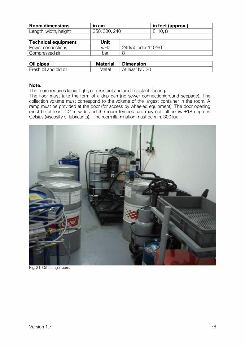
3.2.12 Oil storage room.
All class AIII water-polluting fluids (oil, antifreeze etc.) are stored in this room.
Diagram 45: Representation of oil storage room.
Legend:
1 Oil tank. 2 Oil barrels. 3 Wheeled oil equipment. 4 Power supply.
- Power socket (240 V/50 Hz or 110 V/60 Hz). - Compressed air coupling.
Version 1.7 76
Room dimensions in cm in feet (approx.)
Length, width, height 250, 300, 240 8, 10, 8
Technical equipment Unit
Power connections V/Hz 240/50 oder 110/60
Compressed air bar 8
Oil pipes Material Dimension
Fresh oil and old oil Metal At least ND 20
Note. The room requires liquid-tight, oil-resistant and acid-resistant flooring. The floor must take the form of a drip pan (no sewer connection/ground seepage). The collection volume must correspond to the volume of the largest container in the room. A ramp must be provided at the door (for access by wheeled equipment). The door opening must be at least 1.2 m wide and the room temperature may not fall below +18 degrees Celsius (viscosity of lubricants). The room illumination must be min. 300 lux.
Fig. 21: Oil storage room.
Version 1.7 77
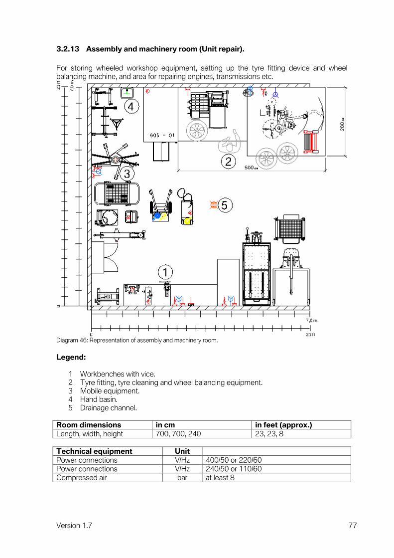
3.2.13 Assembly and machinery room (Unit repair).
For storing wheeled workshop equipment, setting up the tyre fitting device and wheel balancing machine, and area for repairing engines, transmissions etc.
Diagram 46: Representation of assembly and machinery room.
Legend:
1 Workbenches with vice. 2 Tyre fitting, tyre cleaning and wheel balancing equipment. 3 Mobile equipment. 4 Hand basin. 5 Drainage channel.
Room dimensions in cm in feet (approx.)
Length, width, height 700, 700, 240 23, 23, 8
Technical equipment Unit
Power connections V/Hz 400/50 or 220/60
Power connections V/Hz 240/50 or 110/60
Compressed air bar at least 8

Version 1.7 78
Note. This area can take the form of either an open-plan space or an enclosed room. Door opening if enclosed room at least 8,2 feet wide. Provide energy and compressed air supply at regular intervals along the walls. The room illumination must be min. 500 lux. The size of Assembly and machinery room (Unit repair) will be increase concerning dealer size as follow:
BMW XS S M L XL XXL
Work bays 3 – 4 5 – 8 9 – 12 13 – 16 17 – 20 21 – 25
Unit repair 49 m² 49 m² 49 m² 60 m² 65 m² 70 m²
Fig. 22: Assembly and machinery room.
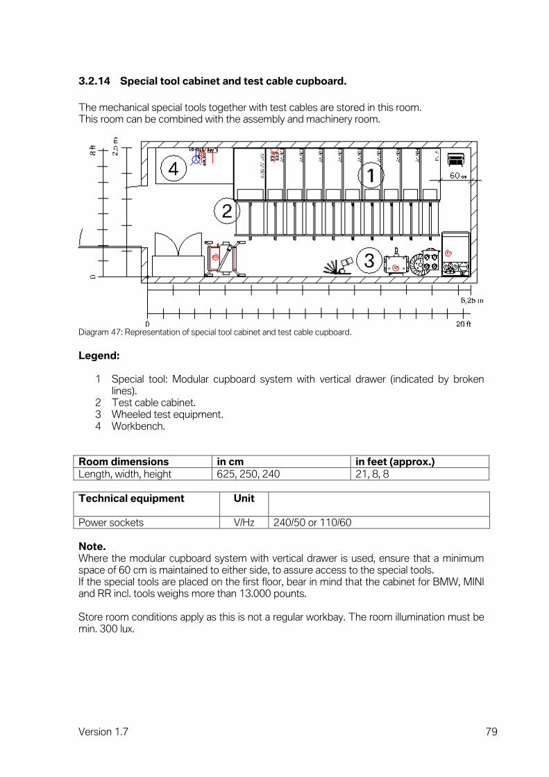
Version 1.7 79
3.2.14 Special tool cabinet and test cable cupboard.
The mechanical special tools together with test cables are stored in this room. This room can be combined with the assembly and machinery room.
Diagram 47: Representation of special tool cabinet and test cable cupboard.
Legend:
1 Special tool: Modular cupboard system with vertical drawer (indicated by broken lines).
2 Test cable cabinet. 3 Wheeled test equipment. 4 Workbench.
Room dimensions in cm in feet (approx.)
Length, width, height 625, 250, 240 21, 8, 8
Technical equipment
Unit
Power sockets V/Hz 240/50 or 110/60
Note. Where the modular cupboard system with vertical drawer is used, ensure that a minimum space of 60 cm is maintained to either side, to assure access to the special tools. If the special tools are placed on the first floor, bear in mind that the cabinet for BMW, MINI and RR incl. tools weighs more than 13.000 pounts. Store room conditions apply as this is not a regular workbay. The room illumination must be min. 300 lux.

Version 1.7 80
Fig. 23: Modular cupboard system with vertical drawer.

Version 1.7 81
3.3 Space concept for body service.
3.3.1 Body workbays.
General workbay for body processes.
Diagram 48: Representation of workbay for body processes.

Version 1.7 82
Legend:
1 Grinding dust extractor arm. 2 Workbench with vice. 3 Mobile tool trolley with set of tools. 4 Energy supply.
- Hoist controls. - Power socket (240 V/50 Hz or 110 V/60 Hz). - Three-phase current socket 400V/32A and 16A. - Compressed air coupling. - LAN connection (2x).
5 Hoist (piston-type or post-type hoists). 6 Exhaust emission extractor (surface-mounted). 7 Welding smoke extractor arm. 8 Straightening bench.
Room dimensions in cm in feet (approx.)
Length, width, height 700, 380, 450 23, 13, 15
Note. Install soundproofing on walls and ceilings. When processing aluminium parts, a separate extractor for explosive dusts is required. This aluminium workbay must in addition be separated from the other workbays by partitions or curtains. In order to avoid dirt from body workbays reaching neighbouring workshop areas, body workbays must be separated from the mechanical or paint workbays.

Version 1.7 83
3.3.2 Removed parts and tools.
For the storage of parts removed during repairs and of tools not currently required.
Diagram 49: Representation of removed parts and tools room.
Legend:
1 Trolley. 2 Storage trolley, body. 3 Mobile devices.
Room dimensions in cm in feet (approx.)
Length, width, height 300, 800, 240 10, 26, 8
Note. Lockable room with 2.5 m access door. Store room conditions apply in this room. 10 m2 per body workbay should be provided for removed parts. The room illumination must be min. 300 lux.

Version 1.7 84
3.4 Space concept for paint service.
The diagram below shows a specimen paint service area. All the necessary functions are visualised in their context, to assure an efficient working process.
Diagram 50: Representation of function bays in the paint service area.
Legend:
1 Painting preparation. 2 Machinery room. 3 Painting and drying booth. 4 Paint store for day's requirements. 5 Paint mixing room. 6 Paint finish.
The individual functions of a paint service area are described in detail in the following sub-chapters.

Version 1.7 85
3.4.1 Paint preparation workbay.
Workbay for preparing vehicles properly for painting. Vehicles can be filled, ground and masked off. If an extractor is installed, filler can also be sprayed on.
Diagram 51: Representation of workbay for paint preparation (section).
Legend:
1 Every workbay (1) with grid (600 cm x 380 cm), sheet tray and paint mist separator mat.
2 Grinding dust extractor arm (incl. power indicator lights) with vacuum cleaner. 3 Painter's work trolley. 4 Extractor for several workbays. 5 Extractor duct. 6 Power supply. 7 Socket (240 V/50 Hz or 110 V/60 Hz). 8 Three phase AC current socket 400V/16A. 9 Compressed air quick connector.
Room dimensions in cm in feet (approx.)
Length, width, height 700, 380, 350 23, 12, 12
Note. The ratio between the paint preparation workbay and the painting booth is 3:1. At least three paint preparation workbays are needed in order to use a painting and drying booth without additional dryer to full capacity. The load of the grid must be designed with 1,000 kg/wheel (minimum 700 kg/wheel).

Version 1.7 86
3.4.2 Painting and drying booth.
For spraying and painting all types of vehicle paints.
Diagram 52: Representation of painting and drying booth (section).
Legend:
1 Painting and drying booth. - Compressed air supply line with fine filter and activated charcoal filter (8 bar).
2 Machinery room (at least 2.75 x 5 m) with service door (2.5 x 2 m). - Connection for heating medium (gas, oil or hot water etc.). - Power connection (400 V/50 Hz). - Air inlet aperture in roof (1 x 1 m). - Air outlet aperture in roof (1 x 1 m). - Exhaust gas pipe ND 150 mm. - Solvent pipe ND 150 mm.
Room dimensions in cm in feet (approx.)
Length, width, height 700, 400, 450 23, 13, 15
Note. Observe national specifications, fire protection and emission regulations and VOC specifications. There must be a gap of at least 6 cm between the outer wall of the painting booth and the building wall to permit assembly. A full-surface floor recess of at least 30 cm (ideally 90 cm) for base filters and air ducts should be provided beneath the painting booth and heater. For spray booths, which work without a floor recess (or were installed subsequently), ensure that the ramp angle is not greater than 8°. In the event of a structure of 30 cm (with ramp angle of 8°), the ramp would be 213 cm long!

Version 1.7 87
All components of the painting booth, and particularly the insulated walls, should be made from non-flammable materials (mineral fibres, not foam).
The load of the grid must be designed with 1,000 kg/wheel (minimum 700 kg/wheel).
Procedure for painting and drying booth for one vehicle Approx. time
1 Bringing the vehicle into the painting and drying booth 5 min
2 Cleaning the surface to be painted 5 min
3 Applying paint and intermediate drying at 20 degrees Celsius 30 min
4 Heating up to 90 degrees Celsius (air temperature) 5 min
5 Drying at 80 degrees Celsius (air temperature) 40 min
6 Cooling down to 20 degrees Celsius and moving the vehicle out of the painting and drying booth
5 min
Total duration of a painting process per vehicle 90 min
The number of painting and drying booths required therefore depends on the desired daily throughput, as each painting and drying booth can be expected to handle five painting throughputs in eight hours. A heat recovery system in the painting and drying booth can only be run in the air extraction mode (painting), not in the air recirculation mode (drying). Thanks to the high total time operating in the air extraction mode (painting), the outlay for a heat recovery system is recouped relatively quickly.
Fig. 24: Painting and drying booth.
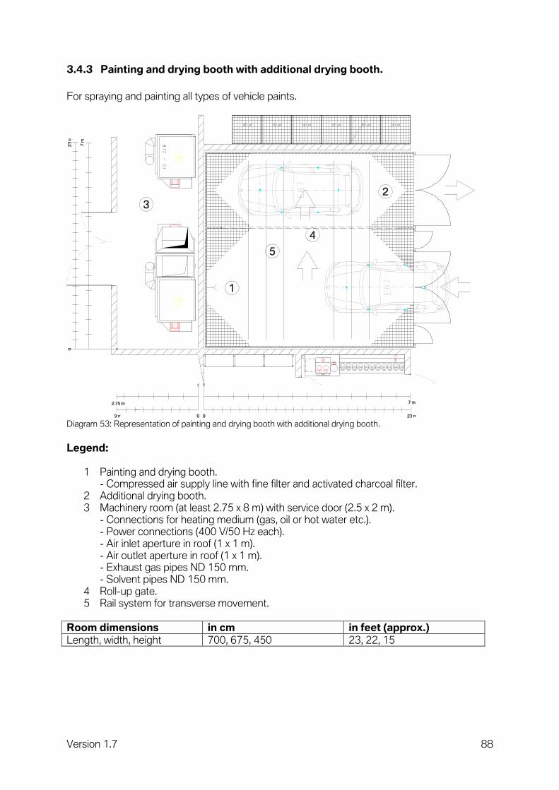
Version 1.7 88
3.4.3 Painting and drying booth with additional drying booth.
For spraying and painting all types of vehicle paints.
Diagram 53: Representation of painting and drying booth with additional drying booth.
Legend:
1 Painting and drying booth. - Compressed air supply line with fine filter and activated charcoal filter.
2 Additional drying booth. 3 Machinery room (at least 2.75 x 8 m) with service door (2.5 x 2 m).
- Connections for heating medium (gas, oil or hot water etc.). - Power connections (400 V/50 Hz each). - Air inlet aperture in roof (1 x 1 m). - Air outlet aperture in roof (1 x 1 m). - Exhaust gas pipes ND 150 mm. - Solvent pipes ND 150 mm.
4 Roll-up gate. 5 Rail system for transverse movement.
Room dimensions in cm in feet (approx.)
Length, width, height 700, 675, 450 23, 22, 15

Version 1.7 89
Note. Observe national specifications, fire protection and emission regulations and VOC specifications. There must be a gap of at least 6 cm between the outer wall of the painting booth and the building wall to permit assembly. A full-surface floor recess of at least 30 cm (ideally 90 cm) for base filters and air ducts should be provided beneath the painting booth and heater. For spray booths, which work without a floor recess (or were installed subsequently), ensure that the ramp angle is not greater than 8°. In the event of a structure of 30 cm (with ramp angle of 8°), the ramp would be 213 cm long! All components of the painting booth, and particularly the insulated walls, should be made from non-flammable materials (mineral fibres, not foam). The load of the grid must be designed with 1,000 kg/wheel (minimum 700 kg/wheel). We recommend additional drying booths with space for two vehicles. Because of the reduced technical outlay required (only drying system), an additional drying booth is cheaper than an additional painting and drying booth. The painting and drying booth always operates at 20 degrees and the dryer always at 80 degrees Celsius (air temperature), avoiding heating-up and cooling-down phases.
Procedure for painting and drying booth plus drying booth for one vehicle.
Approx. time
1 Bringing the vehicle into the painting and drying booth 5 min
2 Cleaning the surface to be painted 5 min
3 Applying paint and intermediate drying at 20 degrees Celsius 30 min
4 Bringing the vehicle into the drying booth 5 min
5 Drying at 80 degrees Celsius (air temperature) 40 min
6 Moving the vehicle out of the drying booth 5 min
Total duration of a painting process per vehicle 90 min
The total duration of a painting process is identical, whether with a painting and drying booth or with a painting and drying booth with additional drying booth. However, as the pure "waiting time" during drying can be used for painting the next vehicle in the case of a painting and drying booth with additional drying booth (see subsequent process), the throughput rises to a maximum of 11 painting throughputs in eight hours. Compared with operating two separate painting and drying booths, this permits a higher throughput even though the booth technology occupies less space and the outlay and energy consumption are lower, by virtue of the fact that the heating-up and cooling-down phases are avoided. The painting preparation workbays should be adapted to take account of this.

Version 1.7 90
Process for painting and drying booth with additional drying booth Approx. time
1 Bringing the first vehicle into the painting and drying booth 5 min
2 Cleaning the surface to be painted on the first vehicle 5 min
3 Applying paint and intermediate drying of the first vehicle at 20 degrees Celsius
30 min
4 Bringing the first vehicle into the additional drying booth 5 min
5 Bringing the second vehicle into the painting and drying booth 5 min
6 Cleaning the surface to be painted on the second vehicle 5 min
7 Applying paint and intermediate drying of the second vehicle at 20 degrees Celsius
30 min
8 Moving the first vehicle out of the additional drying booth and bringing the second vehicle into the additional drying booth
5 min
9 Bringing the third vehicle into the painting and drying booth 5 min
10 Cleaning the surface to be painted on the third vehicle 5 min
11 Applying paint and intermediate drying of the third vehicle at 20 degrees Celsius
30 min
The required number of painting and drying booths with additional drying booth (also available as double dryers for two vehicles) therefore depends on the desired daily throughput. A heat recovery system can only be run in the air extraction mode (painting), not in the air recirculation mode (drying). Thanks to the high overall time operating in the air extraction mode (painting), the outlay for a heat recovery system is recouped rapidly if its capacity is used sufficiently.
Fig. 25: Painting and drying booths with additional drying booths in the longitudinal direction and assemblies
installed above them.

Version 1.7 91
3.4.4 Paint finish workbay.
Workbay for finishing vehicles properly after painting. Vehicles can be polished and cleaned.
Diagram 54: Representation of paint finish workplace (section).
Legend:
1 Mobile work trolley. 2 Shelf for various utensils. 3 Power indicator lights. 4 Power supply.
- Socket (240 V/50 Hz or 110 V/60 Hz). - Compressed air quick connector.
Room dimensions in cm in feet (approx.)
Length, width, height 700, 380, 240 23, 12, 8

Version 1.7 92
3.4.5 Paint store for day's requirements and paint mixing room.
This room serves as the store for the paint required for the current day and is where the paint for the painting process is mixed. The paint mixing room also houses the spray guns, cleaning equipment and a solvent recovery system.
Diagram 55: Representation of paint store for day's requirements and paint mixing room (section).
Legend:
1 Shelves. 2 Paint mixing system. 3 Solvent recovery system. 4 Spray gun cleaning systems (water-based and solvent-based paints). 5 Paint weigher.
Room dimensions in cm in feet (approx.)
Length, width, height 700, 250, 240 23, 8, 8
Technical equipment Unit
Power sockets V/Hz 240/50 or 110/60
Permanent wiring V/Hz 400/50 or 220/60
Note. These rooms are located centrally in the painting zone and require explosion-proof installations and ventilation. The room temperature may not fall below +5 degrees Celsius (water-based paints) or exceed 25°C.

Version 1.7 93
3.4.6 Spot-Repair workbay.
In this workbay, cosmetic repairs are performed on and in the vehicle. Basically, the workbay corresponds to a mechanical workbay. The main requirements on the workbay are:
- It must be shielded and clean. - It must be adequately illuminated (daylight quality / 1,000 lux).
Diagram 56: Representation of Spot repair workbay (section).
Legend:
1 Workbench with vice. 2 Mobile tool trolley with set of tools. 3 Energy supply
- Hoist controls. - Power socket (240 V/50 Hz or 110 V/60 Hz). - Compressed air coupling. - LAN connection.
4 Hoist (piston-type, scissor-type or post-type hoist). 5 Exhaust emission extractor (surface-mounted). 6 Power indicator lights with LAN connection (in each case between two workbays).
Room dimensions in cm in feet (approx.)
Length, width, height 700, 360/380, 450 23, 12/13, 15
Note. Dependent from the type of hoist the width of workbay may be different. When using under floor hoist a width of approx. 12 feet is essential. When using surface-mounted hoist a width of approx. 13 feet is essential.

Version 1.7 94
4 Notes on installation and assembly.
4.1 Installation of hoist.
4.1.1 Installation of underfloor hoist in floor.
Basic details. When laying the base slab, the foundations for the underfloor hoists must likewise be laid. The slope angle required in the structure can be minimised by using additional lost supporting shuttering (A), depending on requirements. The following diagrams show cutaway drawings where this additional supporting shuttering (A) is used. We recommend the use of steel boxes that serve as lost shuttering. This reduces the scope for building faults. The dimensions of the steel box vary according to the type and make of the hoist. The application of force to the base slab varies depending on make and type. The drawing shown here features a product by the J. A. Becker company. Before starting construction work, always request up-to-date plans from the manufacturer. Application of force to the floor. The entire forces may be applied via the support frame (2) or the base of the box (1). Accuracy. The entire technology for the hoist is installed in the steel box. The box must be positioned very accurately along all three axes (x, y and z). If the maximum permitted tolerances are exceeded, it will no longer be possible to install the hoisting system in the box as the hoist would emerge from the floor at an angle. Max. slant of the box along all axes: 1 mm/m Max. height tolerance in relation to finished floor: 0 … +3 mm Max. slant of the support frame along all axes: 1 mm/m Setting. The box is delivered by the hoist manufacturer and set by the construction company. When setting the box, we recommend that this work be supervised by the hoist manufacturer or its site representative. Empty pipe. Depending on hoist type, one or more empty pipes for the electricity cable, control lines or hydraulic lines must be laid between the box and the location of the hoist controls. These empty pipes must be laid using a pull-through wire and with ideally large radii. The radii should be larger than 50 cm.

Version 1.7 95
Working procedure (suggestion):
Diagram 57: Positioning the empty box in the pit.
Positioning the complete box (1) and support frame (2) with the aid of iron rail (4) and support blocks (5). Exact alignment in the pit along all 3 axes. Set any lost shuttering (A) that is required in the pit. Positioning monitored by the hoist manufacturer. The reinforcement (3) supplied by the manufacturer is in the box. Fill lower area of hoist at least with lean concrete (6).
Diagram 58: Sealing the pit.
Fill the pit with lean concrete (8) up to the top edge of the box. Incorporate any reinforcing steel meshes (7) required by the hoist manufacturer. The reinforcing steel meshes reduce the foundation pressure on the box.

Version 1.7 96
Fig. 26: Empty box in enclosed pit.
Diagram 59: Laying empty pipes.
Laying of the empty pipes (9) of the dimensions required by the hoist manufacturer, with pull-through wire, to the planned installed location of the control unit by the construction company. Preparation of the base slab by the construction company.
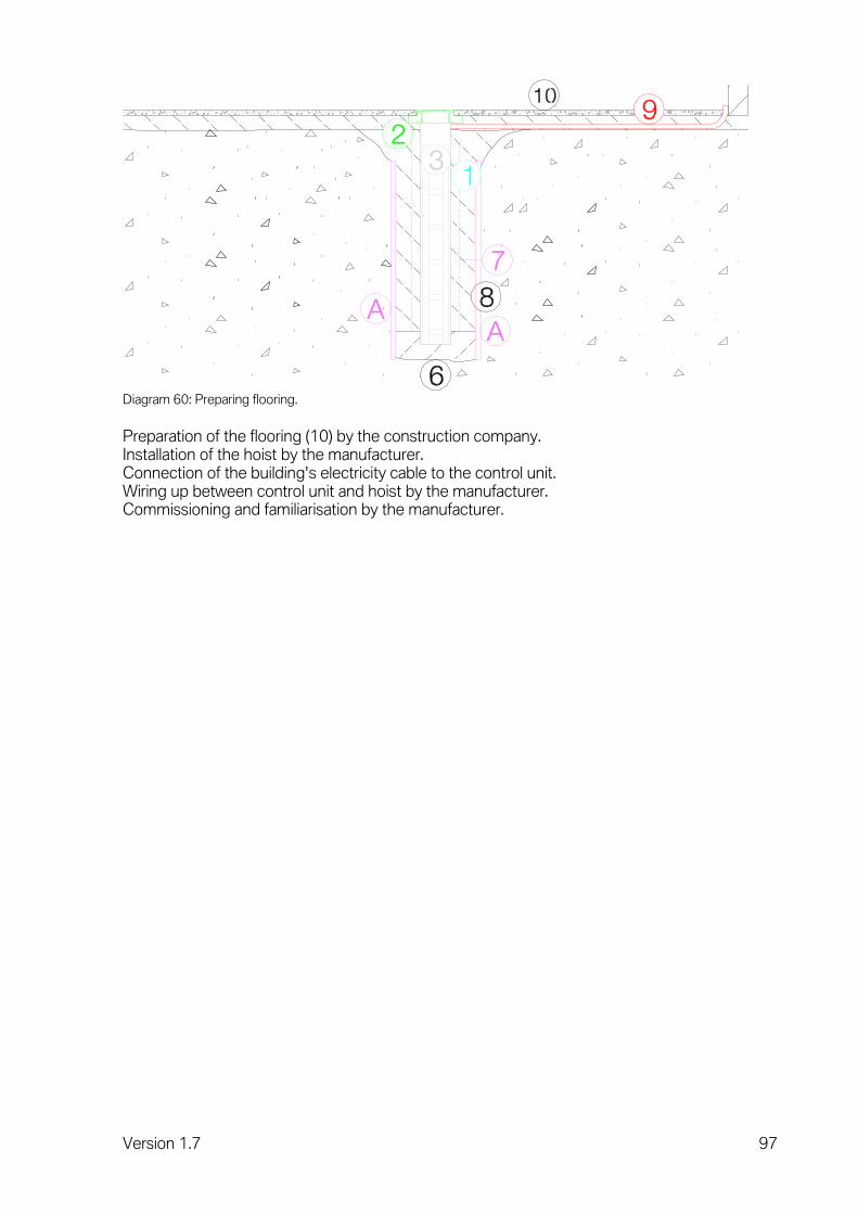
Version 1.7 97
Diagram 60: Preparing flooring.
Preparation of the flooring (10) by the construction company. Installation of the hoist by the manufacturer. Connection of the building's electricity cable to the control unit. Wiring up between control unit and hoist by the manufacturer. Commissioning and familiarisation by the manufacturer.

Version 1.7 98
4.1.2 Underfloor hoist in multi-storey buildings.
Basic details. When laying the floor, the foundations for underfloor hoists must likewise be laid. We recommend the use of steel boxes that serve as lost shuttering. This reduces the scope for building faults. The dimensions of the steel boxes vary according to the type and make of the hoists. The drawing shown here features a telescopic product by the J. A. Becker company. Before starting construction work, always request the latest plans from the manufacturer. Accuracy. The entire technology for the hoist is installed in the steel box. The box must be positioned very accurately along all three axes x, y and z as well as in terms of height. If the maximum permitted tolerances are exceeded, it will no longer be possible to install the hoisting system in the box as the hoist would emerge from the floor at an angle. Max. slant of the box along all axes: 1 mm/m Max. height tolerance in relation to finished floor: 0 … +3 mm Max. slant of the support frame along all axes: 1 mm/m Setting. The box is delivered by the hoist manufacturer and set by the construction company. When setting the box, we recommend that this work be supervised by the hoist manufacturer or its site representative. Empty pipe. Depending on hoist type, one or more empty pipes for the electricity cable, control lines or hydraulic lines must be laid between the box and the location of the hoist controls. These empty pipes must be laid using a pull-through wire and with ideally large radii. The radii should be larger than 50 cm.

Version 1.7 99
Working procedure (suggestion): When preparing the ceiling shuttering (1), an opening that is slightly larger than the hoist box (2) is left. Lower the hoist box (2) into this opening until the adjusting screws (A) rest on the ceiling shuttering.
Diagram 61: Positioning the empty box in the ceiling.
Align the cassette along all three axes and height-wise by means of the adjusting screws, according to the specifications. Close the ceiling shuttering up to the box (2). Lay the empty pipe from the box to the location of the control unit.

Version 1.7 100
Diagram 62: Laying empty pipes.
Prepare the floor. Prepare the flooring. Manufacturer to affix fire protection cladding (3) as required to the outside of the box (2). Installation of hoist by manufacturer. Wiring up of control unit and hoist by the manufacturer. Power (4) connected by engineering services to the hoist's control unit. Familiarisation and commissioning by the manufacturer.

Version 1.7 101
4.1.3 Underfloor hoist installed subsequently on lower floor.
Basic details. The subsequent installation of underfloor hoists in multi-storey buildings used to be a very complex procedure that was difficult to carry out. With the advent of fully hydraulic, synchronised telescopic hoists, subsequent installation has become much more straightforward. At an overall height of approx. 1.3 m and a full stroke of 1.8 m, core holes measuring 2 x 350 mm and 1 x 200 mm in diameter are required. A 70 x 70 cm section of the floor structure is removed around the two 350 mm holes. Once an angle frame with internal measurements of 65 x 65 cm has been assembled at a depth of 35 cm and the floor tiled up to this angle frame, the preparatory building work has been completed. When the hoist has been installed by the manufacturer and the building's power supply connected to the control panel, the hoist is ready for use. All the customary load-bearing equipment has been used on this hoist. All the piston spacings recommended by BMW of 1350, 1500, 1700 and 2300 mm can be achieved.

Version 1.7 102
Working procedure (suggestion):
Diagram 63: Setting the core holes.
Preparing the core holes (1 = 350 mm) and (2 = 200 mm). The hoist is subsequently installed in the two larger holes (1). The control panel will eventually be erected over hole (2). Remove the floor structure around the core holes. Secure an angle frame with the internal measurements 65 x 65 cm precisely over the centre of the holes. The upper edge of the angle frame is flush with the finished floor. Inside the angle frame, prepare a solid surface at a level 35 mm lower (measured from the finished floor). The entire weight of the hoist and vehicle will eventually rest on this surface.

Version 1.7 103
Diagram 64: Installation of the hoist.
Installation of the hoist (4) with hydraulic lines (5) and control panel (6) by the manufacturer. Power supply connected to control panel by engineering services.

Version 1.7 104
Diagram 65: Installed arrangement of the load-bearing equipment for underfloor hoist.
Installation of the chosen load-bearing equipment (7) by the manufacturer. Commissioning and familiarisation by the manufacturer.

Version 1.7 105
Diagram 66: Drawing in perspective of underfloor hoist.

Version 1.7 106
Fig. 27: Floor view of underfloor hoist.
Fig. 28: Ceiling view of underfloor hoist.

Version 1.7 107
Fig. 29: Underfloor hoist for mechanical repairs.

Version 1.7 108
4.2 Installation of two-post hoist.
We recommend that the following conditions (floor quality, floor thickness etc.) be met for setting up all kinds of surface mounted hoists.
Diagram 67: Cutaway drawing and top view of two-post hoist
Minimum dimension of floor slab for a hoist 400 x 500 cm. Floor structure (tiles etc.) 1 .. 6 cm (1). Minimum thickness of floor slab 25 cm (2). Floor slab grade (DIN 1045) C25/30. Retaining bolts - supplied by manufacturer (3). Minimum retaining force of the individual bolts 30 kN.

Version 1.7 109
4.3 Level adjustment of wheel alignment hoist.
The tracks must be levelled by the equipment manufacturer or distributor using an optical levelling instrument (e.g.: Zeiss, Nikon, Leica ….).
The track must be level at the contact point of the turning and sliding plates. The turning and sliding plates must make contact across their entire surface.
The level adjustment of wheel alignment hoist needs to be adjusted loaded with a wheel load of 1000 kp. Equally the adjustment can also be done with a massive vehicle.
Maximum height difference of tracks: (level adjustment in lowest hoist position and at same working height (a))
Working height a
Approx. 1800 mm
Transversally Δhq
max. 0.5 mm
Longitudinally Δhl max. 1.0 mm
Diagonally Δhd max. 1.0 mm
Levelness of tracks A/B max. 0.5 mm
Key to dimensions:
Diagram 68: Dimensions for level adjustment of wheel alignment hoist
Note. Before construction work starts, it is essential to check the various detailed specifications in the manufacturers' installation instructions and foundation plans. The specifications and directives of the industrial accident insurers and the requirements of the Workplaces Ordinance must be observed when choosing the location.

Version 1.7 110
4.4 Pits for test benches and hoists.
This description applies to all types of test bench (e.g. brake or shock absorber tester) as well as to scissor-type hoists that are installed flush with the floor. The description is based on a brake tester made by Beissbarth. Basic details: The test benches and hoists consist of a machine group erected in this pit, and a control and display terminal on a floor stand. Both components are connected to each other by power cables, data lines and hydraulic lines running through an empty pipe located in the floor. All supply lines (electricity, compressed air and data lines) arrive at the control and display terminal. The pits for the machine group require drainage so that liquids can run off and do not cause the technology to malfunction. Two parallel floor pits are required for scissor-type hoists. These two pits must be precisely positioned in relation to one another (height, parallelism and spacing). The installed locations of the machine group and display terminal are defined in the layout plan.

Version 1.7 111
Working procedure (suggestion):
Diagram 69: Preparing base concrete pit.
Preparing the base concrete pit (1). The details supplied by the equipment manufacturers for these pits are finished dimensions. The dimensions in the unfinished state must be correspondingly larger. Preparation of the drain (2) with the dimensions and location required by the equipment manufacturer. Workshop effluent must always be passed through light material separators. Lay empty pipe (3) with the dimensions and location required by the equipment manufacturer, between the pit and the installed location of control and display terminals. Minimum radii of empty pipes 50 cm.
Diagram 70: Alignment of angle iron frame.
Align the height and position of the angle iron frame (4) over the pit and locate it. The upper edge of the finished floor corresponds to the upper edge of the angle iron frame (4). The angle iron frame (4) is at the same height all round. Check that the angle iron frame (4) is square. For hoists, both angle iron frames (4) required need to be aligned very precisely in terms of height, parallelism and spacing. The max. deviation is 3 mm.
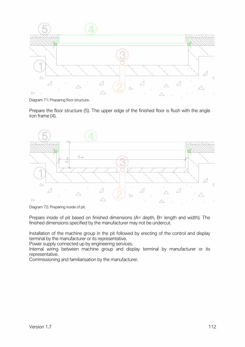
Version 1.7 112
Diagram 71: Preparing floor structure.
Prepare the floor structure (5). The upper edge of the finished floor is flush with the angle iron frame (4).
Diagram 72: Preparing inside of pit.
Prepare inside of pit based on finished dimensions (A= depth, B= length and width). The finished dimensions specified by the manufacturer may not be undercut. Installation of the machine group in the pit followed by erecting of the control and display terminal by the manufacturer or its representative. Power supply connected up by engineering services. Internal wiring between machine group and display terminal by manufacturer or its representative. Commissioning and familiarisation by the manufacturer.

Version 1.7 113
Interface description:
Subject Configuration Delivery
Preparing the inside of the pit / empty pipes
Performed by client Performed by client
Angle iron frame Supplier / manufacturer Supplier / manufacturer
Floor structure Performed by client Performed by client
Hoist / test rig Manufacturer Manufacturer
Fig. 30: Finished pit before installation of the test benches.
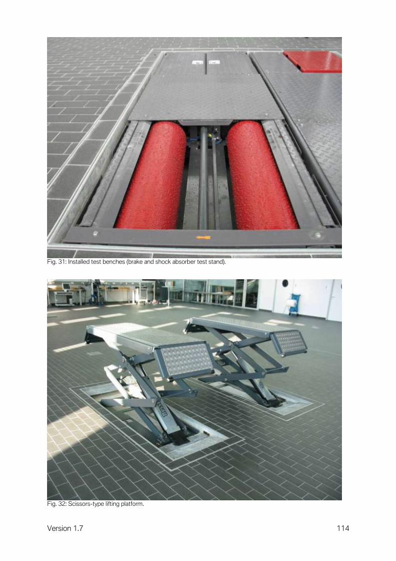
Version 1.7 114
Fig. 31: Installed test benches (brake and shock absorber test stand).
Fig. 32: Scissors-type lifting platform.

Version 1.7 115
4.5 Pits in the painting area.
4.5.1 Painting and drying booth.
Basic details. All tasks involving solvent-based substances can be performed in the painting booth. For reasons of cost, we recommend that fillers and primers should be processed in evacuated preparation bays, and that only high-quality tasks involving top coats and clear coats should be performed in a painting booth. The assemblies for the painting booth can be installed either next to or above the painting booth; note that an internal ceiling height of seven metres is required for overhead installation. A painting booth fundamentally operates in two different modes. In the painting/air extraction operating mode, the painting booth is supplied with fresh air which is heated if necessary. In the drying/air recirculation operating mode, the painting booth is supplied principally with heated outgoing air. Both operating modes are described in detail below. A distinction is made between two non-manufacturer-specific versions of painting booth. Plinth arrangement: A plinth arrangement refers to a painting booth that is installed in a 30 cm deep pit with no sealing between it and the pit. The sole purpose of the pit is to allow vehicles to be driven along the flat into the finished painting booth. These booths can also be placed on an existing floor, though a ramp is then needed for access by vehicles. Advantage: Preparatory construction work required for the pit is straightforward Disadvantage: Poor air routing coupled with shorter base filter service life
making high-quality work more difficult, higher cost of operation Standard arrangement: A standard arrangement means a painting booth that requires a 90 cm deep pit that can then be installed precisely above it. The painting booth and pit represent a unit, so the execution of the pit needs to be very precise. The dimensions, angles and height of the pit's continuous edge must be very accurate. Disadvantage: Preparatory construction work required for the pit is more involved Advantage: Optimum air routing coupled with longer base filter service life,
producing high-quality results, lower cost of operation

Version 1.7 116
Operating principle in painting/air extraction operating mode.
Diagram 73: Operating principle for painting.
The fresh air drawn in (5) (approx 24,000 m3/h) is filtered and then heated up to approx. +20 degrees Celsius and led into the painting booth at roof level. It is broadly distributed there and led into the booth. The paint particles are filtered out by the base filters, and after the air has been passed through the heat exchanger (4) (winter mode) it flows out of the building via the outgoing air duct (6). The base filter, heat exchanger and adjustable flaps create a deliberate backpressure, creating a slight overpressure in the booth that prevents unfiltered air from the paint shop's working areas from entering.

Version 1.7 117
Operating principle in drying/air recirculation mode.
Diagram 74: Operating principle for drying.
Outgoing and incoming air ducts are largely closed. The air from the base zone of the painting booth is heated up further (approx. +80 degrees Celsius) and some fresh air is led back into the painting booth at roof level.
Connection ratings Output Medium
Heating approx. 250 kW Gas, oil or hot water
Electricity up to 20 kW 400 V
Compressed air supply line 400 l/min ND 10 mm

Version 1.7 118
Working procedure for booth in plinth arrangement (suggestion):
Diagram 75: Construction work to be performed by client for booths in plinth arrangement.
Prepare a 30 cm deep pit (1) of the dimensions required by the manufacturer. Prepare the necessary roof openings (2) for outgoing air duct, incoming air duct and combustion air duct. Prepare any roof anchoring points needed.

Version 1.7 119
Diagram 76: Painting booth setup for plinth arrangements
Preparation of the entire painting booth (3) with all roof assemblies (4-9) by the manufacturer. Running all energy media to heating unit (heating energy, electricity, compressed air). Running the compressed air line into the painting booth. Power supply and heating energy connected up by engineering services. Commissioning and familiarisation by the manufacturer. Dimension (A) corresponds at least to the max. possible depth of snow on the roof or to the official stipulations.

Version 1.7 120
Working procedure for booth in standard arrangement (suggestion):
Diagram 77: Construction work to be performed by client for booths in standard arrangement.
Prepare a 90 cm deep pit (1) of the dimensions required by the manufacturer. The painting booth is erected over this pit and the heating unit in a separate room. The manufacturer's dimensions quoted are finished dimensions. The surface of this pit must be dust-resistant. Prepare the necessary roof openings (2) for outgoing air duct, incoming air duct and combustion air duct. Prepare any roof anchoring points needed.

Version 1.7 121
Diagram 78: Assembly of angle iron frame for booths in standard arrangement.
Assembly of the angle iron frame (3) supplied by the manufacturer above the pit. These angle iron frames must be positioned very precisely in respect of their angle and height. We recommend that the manufacturer supervises this work.
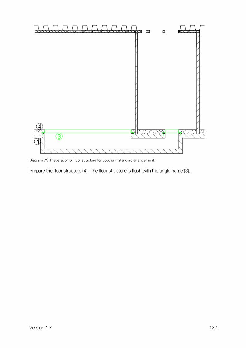
Version 1.7 122
Diagram 79: Preparation of floor structure for booths in standard arrangement.
Prepare the floor structure (4). The floor structure is flush with the angle frame (3).

Version 1.7 123
Diagram 80: Painting booth setup for standard arrangements.
Preparation of the entire painting booth with all roof assemblies by the manufacturer. Running all energy media to heating unit (heating energy, electricity and compressed air). Running the compressed air line into the painting booth. Power supply and heating energy connected up by engineering services. Commissioning and familiarisation by the manufacturer. Dimension (A) corresponds at least to the max. possible depth of snow on the roof or to the official stipulations.

Version 1.7 124
Interface description:
No. Topic Supplier Assembly
1 Pit Client Client
2 Roof openings Client Client
3 Angle iron frames Client Client
4 Floor structure Client Client
5 Painting booth Booth manufacturer Booth manufacturer
6 Heating unit Booth manufacturer Booth manufacturer
7 Outgoing air duct Booth manufacturer Booth manufacturer
8 Incoming air duct Booth manufacturer Booth manufacturer
9 Combustion air flue Booth manufacturer Booth manufacturer
10 Anchoring for air ducts Booth manufacturer Booth manufacturer
11 Roof collar Booth manufacturer Booth manufacturer
12 Roof seal Client Client
13 Anchoring points Client Client

Version 1.7 125
4.5.2 Paint preparation bays.
The base materials for painting (filler and primer) can be processed and all dry grinding work performed at a paint preparation bay. For this, we recommend a full-surface grid with extraction and a central extractor to which grinding tools can be connected directly. A grid prevents build-ups of dust on the floor, and all the adverse consequences of this. Fully or partly transparent roller curtains are useful for separating off the individual workbays. High-quality lighting is essential.
Diagram 81: Top view and cutaway drawing of the air duct for paint preparation bays.

Version 1.7 126
Legend: 1 = angle iron frame to serve as grid surround. 2 = air ducts for extraction. 3 = grid. 4 = substructure for grid.
Diagram 82: Top view of paint preparation bays.
5 = extractor for up to four paint preparation bays. 6 = roller curtains between the workbays.
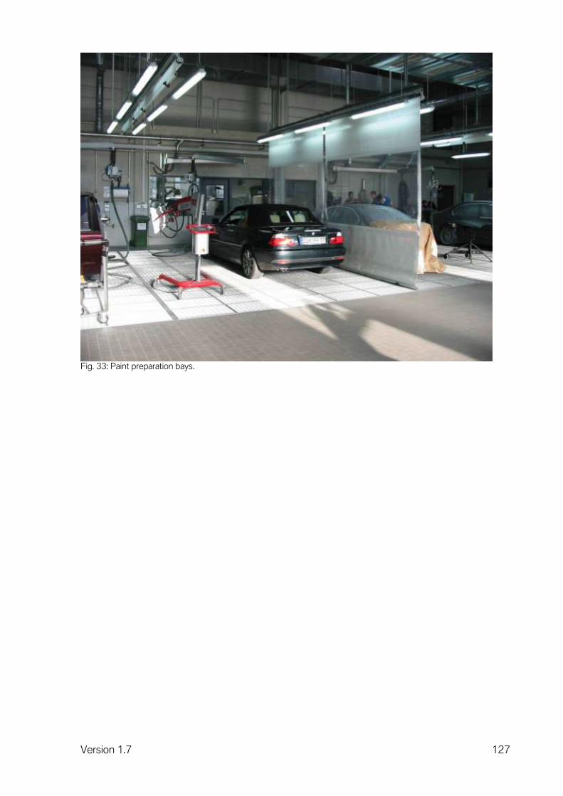
Version 1.7 127
Fig. 33: Paint preparation bays.

Version 1.7 128
4.6 Surface-mounted exhaust emission extractor. Exhaust emission extractor in the workshop for working with running engine (near idling operation). Exhaust gas is always emitted when a combustion engine is running! There is a risk when there are hazardous substances in the air in the breathing area of the employees. Therefore, use exhaust emission extractors when working with a running engine. The legal requirements in the exhaust emission area must be observed. In general, a distinction is made between underfloor and surface-mounted exhaust emission extractors. Underfloor exhaust emission extractors are described in chapter 4.7. At the moment it is mainly surface-mounted exhaust emission extractors that are being considered in the BMW workshops being planned. Possible surface-mounted exhaust emission extractors are:
Hose reel (wall- or ceiling-mounted). Suitable for one to two workbays.
Suction rail with trolley. Suitable for several workbays.
The optimal assembly height of a suction rail or hose reel is approx. 4 m / 13 feet (lower edge) and must be coordinated with the lighting fittings. The distance between the suction rail and the centre of the vehicle hoist should be 3.5 m / 11,5 feet. The hose length is 5 m / 16 feet. For suction rails longer than 12 m / 39 feet, it is recommended to position the ventilator in the centre of the suction rail. Suction rails are available in lengths up to 40 m / 131 feet. The hose should be temperature-resistant for mechanical workbays up to 200 °C. For applications of the exhaust emission extractor during exhaust-gas tests, hoses with a temperature resistance of up to 600°C are required, depending on market-specific legal regulations. If there are several trolleys in a system, then automatic throttle valves are considered, which are controlled by the weight of the suction hose or the operation of the balancer. The extraction is only performed where it is needed. A separate suction rail with suitable ventilator should be installed for the right and left side of the workshop, in order to be able to use the system flexibly and economically. For larger central systems, the use of a frequency inverter may be recommended (energy saving). The corresponding volumetric flows must be considered in the workshop operation for each passenger car:
Service/Repair: 350 m³/h – 450 m³/h (hose = 100 mm / 4 inches)
Testing stations or exhaust-gas test: 700 m³/h – 1,200 m³/h (hose = 150 mm / 6 inches) (motorbike 100 m³/h – 350 m³/h) The simultaneity factor is important for the calculation of the extraction quantity/ventilator power. We are assuming a simultaneity factor of 50%. This means that at 10 possible extraction points a maximum of 5 are running simultaneously. An extraction point must be considered at approx. 50% of all mechanical workbays. However, at least two extraction points are required, in order to satisfy twin-pipe exhaust systems.
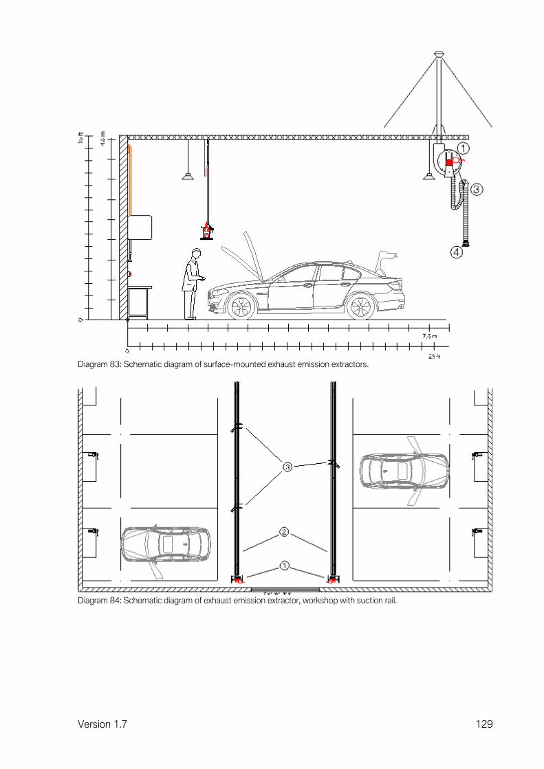
Version 1.7 129
Diagram 83: Schematic diagram of surface-mounted exhaust emission extractors.
Diagram 84: Schematic diagram of exhaust emission extractor, workshop with suction rail.

Version 1.7 130
Legend:
1 Ventilator. 2 Suction rail. 3 Trolley unit with balancer and hose (5 m / 16 feet). 4 Collection element (exhaust sockets or funnel).
Technical equipment Unit
Permanent wiring V/Hz 400/50 or 240/60
Note. The exhaust gases are guided via an intake pipe to the ventilator, and from there are directed outwards over the roof into the open air via the pressure line. The market-specific legal regulations must be observed. Interface description.
No. Topic Supplier Assembly
1 Suction rail or hose reel Manufacturer Client/Supplier
2 Ventilator with consoles Manufacturer Client/Supplier
3 Pressure line, roof duct and deflector hood
Manufacturer Client/Supplier
4 Power supply at the ventilator and current lead from the fan to the button
Client Client

Version 1.7 131
Fig. 34: Suction rail with hose and exhaust socket.
Fig 35: Suction rail with hose and exhaust socket.

Version 1.7 132
4.7 Underfloor exhaust emission extractor, installation in floor.
Basic details. Before the floor slab is prepared, the pipe network for the entire extractor system must be installed. There is a free choice of material, although the stub pipe should be made of a heat-resistant material (up to min. 160° C), so that inserted hot extractor hoses will not stick fast. The pipe network starts with a floor connection behind every workbay. The hose bearing is beneath the floor connection. After the hose bearing, there is a stub pipe at least 3 metres long with a minimum diameter of 125 mm. This stub pipe is laid as a straight piece, with no elbows and with smooth pipe transitions. The stub pipe serves as the storage location for the exhaust gas hose, with the extractor funnel located in the hose bearing to prevent the exhaust gas hose from slipping too far down. The stub pipe is made from temperature-resistant material so that hot (max. +120 degrees Celsius) exhaust gas hoses do not become stuck to it when pushed in. All stub pipes lead into a manifold with a diameter of at least 150 mm. The manifold leads into an inspection shaft. The entire pipe network is laid sloping downwards towards the inspection shaft. The shaft is liquid-tight and at least 50 cm deeper than the end of the manifold. This allows liquids and foreign bodies to collect in the shaft without influencing the functioning of the system. The suction pipe leads from the top of this collection shaft to the fan, and the exhaust gases are then led outside through the roof via the pressure pipe. We recommend connecting a maximum of ten workbays to one fan. Larger systems may produce an unacceptable level of noise due to the higher extracting performance and the floor covers may be very difficult to open. The exhaust gas fan should be installed in an ancillary room to keep the noise level down. The exhaust gas fan is connected directly to the power supply by engineering services. A power line is installed by the client between the electric fan and the switch. The roof seal for the pressure pipe is provided by the client.

Version 1.7 133
Working procedure (suggestion):
1.
Diagram 85: Preparation of the underfloor pipes with inspection shaft.
Preparation of the inspection shaft (1) with connection for suction pipe (4). Laying the stub pipes and manifold (2) with hose bearing (3).
2.
Diagram 86: Preparation of the floor slab.
Preparation of the floor slab.
3.
Diagram 87: Preparation of the floor structure with floor connections.
Preparation of the floor structure including laying the floor connections (5) and angle frame for the inspection shaft cover (6).

Version 1.7 134
4.
Diagram 88: Preparation of the suction and extractor pipes.
Preparation of the suction pipes (7) and installation of the fan (8) with brackets. Preparation of the pressure pipe (9) with roof passage and deflector hood Preparation of the roof seal. Height of deflector hood above roof must be at least snow depth, or to satisfy official requirements.
Diagram 89: Fully underfloor exhaust emission extractor, installation in floor.

Version 1.7 135
Interface description:
No. Topic Supplier Assembly
1 Inspection shaft Client Client
2 Stub pipe, manifold Client Client
3 Hose bearing Workshop service Client
4 Pipe elbow and suction pipe Client Client
5 Floor connections Workshop Equipment Client
6 Inspection shaft cover Client/Manufacturer Client
7 Suction pipe Manufacturer Client/Supplier
8 Fan with brackets Manufacturer Client/Supplier
9 Pressure pipe, roof passage and deflector hood
Manufacturer Client/Supplier
10 Power connection to fan and power line from fan to operating switch
Client Client

Version 1.7 136
4.8 Underfloor exhaust emission extractor, installation in ceiling.
Working procedure (suggestion):
Diagram 90: Openings in floor for installation in ceiling.
Behind every workbay there is an opening (1) in the floor measuring approx. 27 x 27 cm.
Diagram 91: Use of hose bearing for installation in ceiling.
The hose bearing (2) is set in this floor opening and the gap between the hose bearing and floor opening filled with concrete by the client.

Version 1.7 137
Diagram 92: Preparation of flooring for installation in ceiling.
When the flooring is prepared by the client, the floor cover is set flush with the tiles, over the hose bearing.
Diagram 93: Stub pipes for installation in ceiling.
After the hose bearing, there is a stub pipe (4) at least 3 metres long with a minimum diameter of 125 mm. This stub pipe is laid as a straight piece, with no elbows or transitions. The entire pipe network must be made from fireproof material and be laid sloping downwards towards the pipe (7).
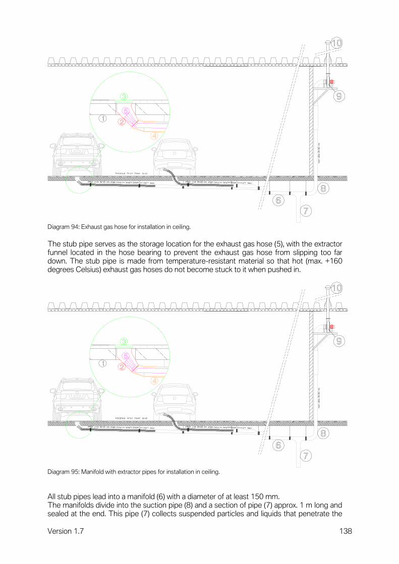
Version 1.7 138
Diagram 94: Exhaust gas hose for installation in ceiling.
The stub pipe serves as the storage location for the exhaust gas hose (5), with the extractor funnel located in the hose bearing to prevent the exhaust gas hose from slipping too far down. The stub pipe is made from temperature-resistant material so that hot (max. +160 degrees Celsius) exhaust gas hoses do not become stuck to it when pushed in.
Diagram 95: Manifold with extractor pipes for installation in ceiling.
All stub pipes lead into a manifold (6) with a diameter of at least 150 mm. The manifolds divide into the suction pipe (8) and a section of pipe (7) approx. 1 m long and sealed at the end. This pipe (7) collects suspended particles and liquids that penetrate the

Version 1.7 139
pipe system, to ensure that they do not interfere with the system's functioning. The suction pipe leads to the fan (9). The exhaust gases are led outside by the fan, passing through the roof via the pressure pipe and deflector hood (10). The roof opening is made and sealed by the client. We recommend connecting a maximum of ten workbays to one fan. Larger systems may produce an unacceptable level of noise due to the higher extracting performance and the floor covers may be very difficult to open. The entire pipe network is laid sloping downwards towards the pipe (7). Height of deflector hood above roof must be at least snow depth, or to satisfy official requirements. Interface description:
No. Topic Supplier Assembly
1 Floor Client Client
2 Hose bearing Manufacturer Client
3 Floor connection Manufacturer Client
4 Stub pipes Client Client
5 Extractor hose Manufacturer Client/Supplier
6 Manifold Client Client
7 Blind pipe Client Client
8 Suction pipe Manufacturer Client/Supplier
9 Fan with brackets Manufacturer Client/Supplier
10 Pressure pipe with roof collar Manufacturer Client/Supplier
11 Deflector hood Manufacturer Client/Supplier

Version 1.7 140
4.9 Multifunctional hall.
Request up-to-date plans from the manufacturer before starting detailed planning. Working procedure (suggestion):
Diagram 96: Foundations plan for multifunction hall.
- Setting the hoist box (2), see Installation of hoist 4.1.
- Preparation of the drain (1) to the petrol trap or water treatment system.
- Preparation of the petrol and oil-resistant floor slab with settling pit (3).
- Preparation of the full-surface grid that can rest directly on the floor.
Requirements for surface of grid:
- Smooth. - Mesh dimension approx. 3 x 3 cm. - Load capacity 1000 kp per wheel.

Version 1.7 141
Diagram 97: Layout plan of multifunction hall.
- Assembly of the hoist (9) and control stand (7) with internal wiring by the
manufacturer.
- Electrical connection (7) by engineering services.
- Energy supply with connections (6) by engineering services(electrical installation must be suitable for wet room and be hose-proof).
- Assembly of sectional gate (8).
- Delivery and assembly of the high-pressure cleaner (5) in the ancillary room (4) that is for the storage of cleaning equipment and cleaning agents. An extractor flue must be provided for the high-pressure cleaner.
- Commissioning of and familiarisation with the hoist by the manufacturer. Interface description.
Topic Supplier Assembly
Pit preparation Client Client
Hoist steel box Manufacturer Client
Hoist Manufacturer Manufacturer
Operating unit Manufacturer Manufacturer
Grid Client Client
Flue Client Client

Version 1.7 142
4.10 Portal car wash.
Diagram 98: Foundations plan for portal car wash.
Working procedure (suggestion):
- Preparation of the drainage channel (3) of the dimensions required by the manufacturer, incl. angle frame and grid cover.
- Preparation of the drain (1) from the drainage channel to the petrol trap or water
treatment system.
- Preparation of the floor rails (2) for subsequent assembly of the portal car wash rails (upper edge of rails flush with the finished floor).
- Preparation of the hall floor sloping downwards from the walls to the drainage
channel (note manufacturer's details of slope).
- Installation of grid
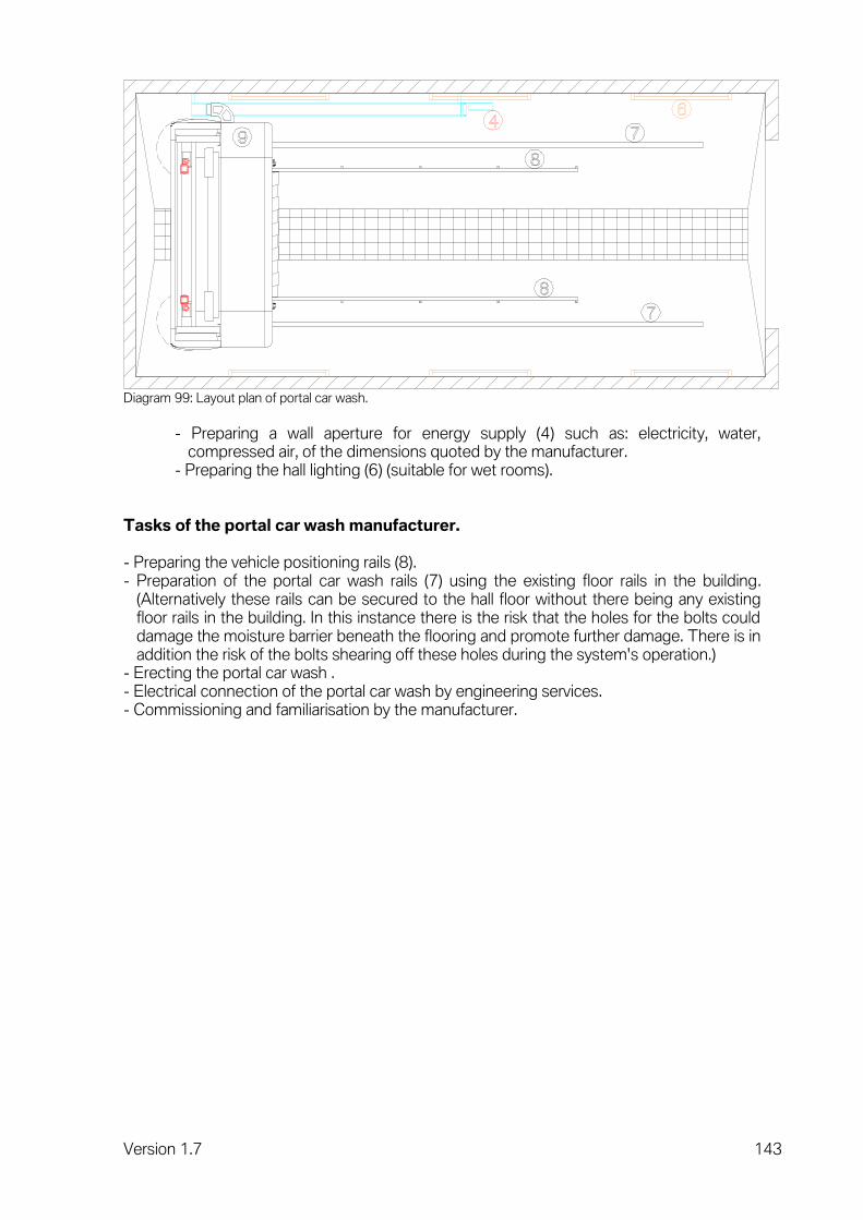
Version 1.7 143
Diagram 99: Layout plan of portal car wash.
- Preparing a wall aperture for energy supply (4) such as: electricity, water,
compressed air, of the dimensions quoted by the manufacturer. - Preparing the hall lighting (6) (suitable for wet rooms).
Tasks of the portal car wash manufacturer. - Preparing the vehicle positioning rails (8). - Preparation of the portal car wash rails (7) using the existing floor rails in the building.
(Alternatively these rails can be secured to the hall floor without there being any existing floor rails in the building. In this instance there is the risk that the holes for the bolts could damage the moisture barrier beneath the flooring and promote further damage. There is in addition the risk of the bolts shearing off these holes during the system's operation.)
- Erecting the portal car wash . - Electrical connection of the portal car wash by engineering services. - Commissioning and familiarisation by the manufacturer.
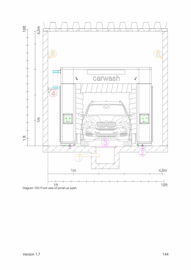
Version 1.7 144
Diagram 100: Front view of portal car wash.

Version 1.7 145
Diagram 101: Side view of portal car wash.
Interface description.
No. Topic Supplier Assembly
1 Drain Client Client
2 Floor rails Client Client
3 Drainage channel Client Client
4 All energy supply lines Client Client
5 Sectional gate Client Client
6 Hall lighting Client Client
7 Rails for portal car wash Manufacturer Manufacturer
8 Vehicle positioning rail Manufacturer Manufacturer
9 Portal car wash with energy rail Manufacturer Manufacturer
Note. Waste water legislation varies considerably from country to country and must be complied with. An ancillary room for pumps, chemical containers etc. must be provided. The size of this room depends considerably on the supplementary equipment chosen for the portal car wash and on national specifications calling for settling tanks and other technical features.

Version 1.7 146
4.11 Roof passages.
Required for exhaust emission extractors, for painting booths and for welding smoke extractors and grinding dust extractors.
Planning procedure Responsible
Defining roof passages Workshop service
Defining size Workshop service
Defining exact location Client
Execution procedure Responsible
Preparing the roof opening Client
Preparing the necessary anchor points Client
Defining the minimum height of extractor pipes Client
Preparing the extractor pipe with roof collar and deflector hood Client/Supplier
Preparing the anchor cables Client/Supplier
Roof seal Client

Version 1.7 147
5 Workshop waste water treatment. Workshop waste water may be contaminated with light materials (e.g. oil, petrol), suspended particles (e.g. dust, sand, abraded metal) and chemicals (e.g. brake fluid, screenwash). Waste water contaminated in this way may not seep into the ground or be discharged into the public sewer network without first being treated. There are workshops without a waste water pipe network. At such workshops, the liquids occurring are sucked up from the floor by treatment equipment and disposed of. Avoiding/reducing waste water can eliminate the need for treatment systems or minimise the requirements. In regions where high amounts of water drip onto the floor (e.g. melt water from snow on vehicles), such solutions may prove inadequate. In many countries there are precise specifications stating the maximum permitted levels of contamination in waste water. These specifications serve as the basis when designing and dimensioning waste water treatment systems. The basic components of a waste water treatment system for workshop waste water are listed below and their operating principles explained. These components must be dimensioned to reflect the level of waste water occurring. Depending on the maximum permitted residual level of contamination in the waste water, further treatment and filtration modules may need to be added. Waste water from a car dealership (office area, kitchen area, sanitation area, etc.) may not be mixed with the workshop waste water in the same pipework system. It may be advisable to install separate pipework systems within the same workshop area, e.g. to allow the water from a car wash to be recycled. Each type of waste water requires a different cleaning system. The more the various types are kept apart, the easier their subsequent treatment will be.
Diagram 102: Representation of waste water treatment.

Version 1.7 148
Legend:
1 Sludge trap. 2 Light materials separator. 3 Coalescence separator. 4 Drain with float closure. 5 Sampling shaft.
The individual operating principles are explained in the following chapters.
5.1 Sludge trap.
Suspended particles that are heavier than water settle in the sludge trap. This trap uses the gravity principle. It is consequently necessary to ensure that the waste water remains in this tank for as long as possible. A sufficiently large tank reduces the flow rate and ensures that the waste water remains in the tank for the desired period of time. While the heavy suspended particles settle on the base of the tank, the light particles float to the top and are carried into the light materials separator along with the waste water. The fact that the light materials float upwards in the sludge trap also increases the effectiveness of the light materials separator. The settled suspended particles must be drained off and disposed of properly at regular intervals.
5.2 Light materials separator.
Substances that are lighter than water are trapped in this tank. This trap uses the gravity principle. The longer the waste water remains in this tank, the more light material floats to the top and can be trapped. The drain for this tank is close to its base, as a result of which only the heavier waste water can drain off. The light materials mixture floating on the water must be extracted and disposed of properly at regular intervals. If it is not removed regularly, the layer of light materials will become increasingly thick and the water level will fall, causing the float to close the drain.
5.3 Coalescence separator.
Minute droplets of oil take an extremely long time to float to the top. The task of the coalescence separator is to combine these minute droplets of oil so that the larger droplet can float upwards faster. The coalescence separator consists of a large number of corrugated plates arranged closely together. When the waste water flows past these plates, the minute droplets of oil cling to the plates' surface and are combined with other droplets of oil, enabling them to float to the top. Droplets of oil combine with minute suspended particles to form a very fine sludge between the plates, gradually impairing the effect of the coalescence separator. To remove this very fine sludge, the plate system must be removed and washed down with a high-pressure cleaner.

Version 1.7 149
5.4 Sampling shaft.
The waste water discharged can be sampled in this shaft and residual levels of contamination measured.
5.5 Combinations.
The sludge trap and light materials separator can be grouped together in a single tank.
5.6 Extensions.
Substances dissolved in the water (e.g. salts) or chemicals cannot be filtered out by gravity. Biological or chemical filtration systems are needed to filter out these substances. The decision on whether to install such an additional system and its planning should be entrusted to a specialist company. The normal approach is to install the components mentioned further above first, and then to add further components if required.