planning whole-body humanoid locomotion, reaching, and manipulation · planning whole-body humanoid...
TRANSCRIPT

Planning Whole-body Humanoid Locomotion,Reaching, and Manipulation
Eiichi Yoshida, Claudia Esteves, Oussama Kanoun, Mathieu Poirier, AnthonyMallet, Jean-Paul Laumond and Kazuhito Yokoi
Abstract In this article we address the planning problem of whole-body motions byhumanoid robots. The presented approach benefits from two cutting edges of recentadvancement in robotics: powerful probabilistic geometric and kinematic motionplanning and advanced dynamic motion control for humanoids. First, we introducea two-stage approach that combines these two techniques for collision-free simul-taneous locomotion and upper-body task. Then a whole-body motion generationmethod is presented for reaching including steps based on generalized inverse kine-matics. The third example is planning of whole-body manipulation of large objectby “pivoting”, by making use of the precedent results. Finally, an integrated experi-ment is shown in which the humanoid robot interacts with its environment throughperception. The humanoid robot platform HRP-2 is used as the platform to validatethe results.
1 Introduction
As the progress in the hardware of humanoid robot has recently been accelerated,a number of applications is now expected. Their anthropomorphic shape is advan-
Eiichi Yoshida and Kazuhito YokoiCNRS-AIST JRL (Joint Robotics Laboratory), UMI 3218/CRT, National Institute of AdvancedIndustrial Science and Technology (AIST), Umezono 1-1-1, Tsukuba, Ibaraki, 305-8568, Japan,e-mail: {e.yoshida,Kazuhito.Yokoi}@aist.go.jp
Claudia EstevesFacultad de Matematicas, Universidad de Guanajuato, Guanajuato, 36000 Gto., Mexico. e-mail:[email protected]
Oussama Kanoun, Mathieu Poirier, Anthony Mallet and Jean-Paul LaumondLAAS-CNRS, 7 avenue du Colonel Roche, F-31077 Toulouse, and Universite de Toulouse ; UPS,INSA, INP, ISAE ; LAAS ; F-31077 Toulouse, France.e-mail: {okanoun, mpoirier, mallet, jpl}@laas.fr
1

2 E. Yoshida, et al.
tageous in moving in environments designed for humans, using the machines ortools designed for humans, and also performing interactions and assistive tasks forhumans. For the humanoid to execute effective tasks, the whole-body motion coor-dination is indispensable. The humanoid motion is characterized by its redundancyand underactuation. The former is obvious, as humanoid robots have usually morethan thirty degrees of freedom. The latter means the “base frame” of a humanoidrobot, for example its waist, can only be controlled indirectly by articulated legs,unlike wheeled mobile robots. In this article, in order to tackle this planning prob-lem of whole-body humanoid motions, we present the approaches that combine theprobabilistic geometric/kinematic motion planning and the dynamic motion gener-ation as follows. At the planning stage, the global humanoid motion is modeled bya kind of vehicle with the bounding volume that is fully actuated to plan the ba-sic path. It is then transformed into dynamically executable humanoid motion bythe dynamic motion generator. The whole-body humanoid motions handled in thisarticle include collision-free locomotion, reaching and manipulation.
In the rest of this section, we briefly introduce the basic planning tools and thesoftware and hardware platform which is the common part throughout this article.In Section 2, a two-stage approach for collision-free locomotion is presented. Thenwe address the dynamic whole-body motion generation by taking the example ofreaching including stepping in Section 3. The whole-body manipulation is then dealtwith in Section 4 by benefiting from both the collision-free path planning techniqueand whole-body motion generation. An experiment that integrates the planning andperception is described in Section 5 by using the humanoid robot HRP-2 beforeconcluding the article.
1.1 Basic motion planning methods
For complex robotic systems like humanoid robots, it is reasonable to employ ef-ficient algorithms based on probabilistic planning methods such as diffusing meth-ods like Rapidly-exploring Random Trees (RRT) [11, 23] or sampling method likeProbabilistic RoadMap (PRM) [17] and all their variants (see [4, 22] for recentoverviews). In those methods, the path search is usually made in the configurationspace such as the joint angles. The probabilistic methods compute a graph called aroadmap whose nodes are collision-free configurations chosen at random and whoseedges model the existence of collision-free local paths between two nodes.
In probabilistic planning method, the graph is built incrementally by shootingconfigurations at random. Configurations and local paths between them are includedin the graph as soon as they are collision-free. This construction of the graph iscalled the learning phase. Once the graph is built, then the query phase consistsin first adding both starting and goal configurations of the given problem to theroadmap, and then search the graph for a path.
On the other hand, in diffusing methods the graph is built gradually by expand-ing the tree from the start and/or goal configurations. After a configuration is ran-

Planning Whole-body Humanoid Locomotion, Reaching, and Manipulation 3
domly generated, the nearest configuration is identified. Then a new configurationis computed that advances by a given distance from the nearest node to towardsthe randomly generated one. If this new configuration and the local path to it arecollision-free, then they are added to the graph as a new node and a new edge. Thisdiffusion is repeated until a path is found that connects the start and goal configura-tions.
In this way, the probabilistic motion planner eventually finds collision-free pathsas connected components of the roadmap, which is proven as probabilistic com-pleteness. There are several important components in implementing this probabilis-tic motion planning: collision checkers, steering methods and path optimizers. Col-lision checkers validate configurations and paths. Any available free or commerciallibraries can be used for this function. A “steering method” is a method that com-putes an admissible path from an initial configuration to final one in the absence ofobstacle. In this article, dedicated steering methods are devised depending on theplanning problems. Finally, since paths planned by probabilistic motion plannersare often redundant, a “path optimizer” is necessary to remove the redundant partsto obtain a shorter path. For instance, we can employ the “adaptive shortcut” pathoptimization algorithm proposed by [11].
As described later in Section 2, we generally adopt a two-stage approach forwhole-body motion planning. At the first stage, the basic geometric and kinematicmotion planner described here is applied to collision-free path planning for a simpli-fied model of the humanoid, like its bounding volume. This is because the compu-tation cost would be too high if random sampling is directly applied to the complexdynamic system with many degrees of freedom.
1.2 Hardware and software platform
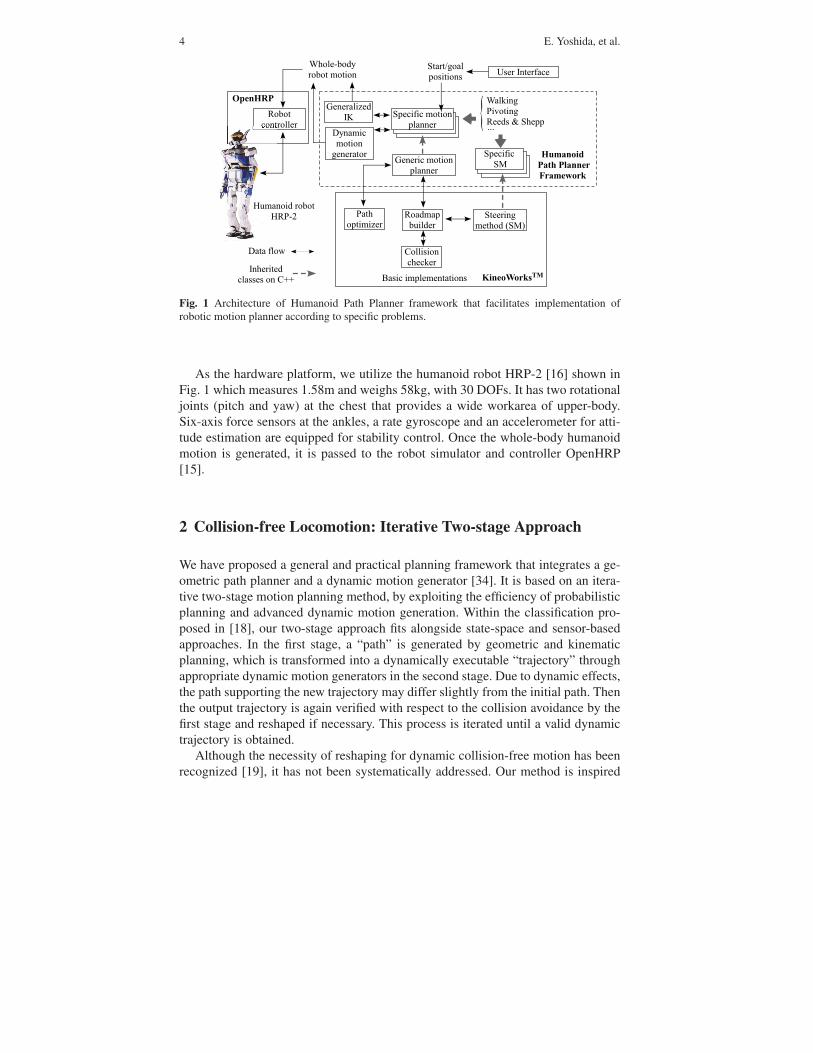
We implement motion planners presented in this article in a common softwareframework “Humanoid Path Planner” [36] on the basis of the motion planningsoftware kit KineoWorksTM [21] as shown in Fig. 1. As illustrated lower part inFig. 1, this software kit provides the basic methods of planning like PRM or RRTas “roadmap builders”, as well as the aforementioned basic functions of collisionchecking mechanism, a template of steering method and path optimizers.
The object-oriented architecture allows the users to define the specific plannerdepending on the tackled problem as an inherited class of a general robot motionplanner. The planner takes care of interaction with basic functions introduced in1.1. The problem-specific components, especially steering methods for walking andmanipulation are inherited from the template including basic functions. Since thebasic interface of class definition of the general framework is common, it is rela-tively easy to implement those problem specific parts once the planning problem isdefined.
The HPP framework also includes a walking pattern generator presented in Sec-tion 2 and a dynamic whole-body motion generator in Section 3.
4 E. Yoshida, et al.
������������ � ����
���������� ���������
�������������
� ��������� ��������
���������� ���������
�����������
������ ����������������
�� ���� ������������!��
"� ��� ���#��
����������
$���%���&����� ��� ���
� �� '������� ����
��������
��������������
���������
���� ���
���� �
��� ����
(������ ������
�������#���
�)
�&������
�� ����
������ ��
$�!����
"�*� ����
������+�����,,,
-������������ �
-�"%.
Fig. 1 Architecture of Humanoid Path Planner framework that facilitates implementation ofrobotic motion planner according to specific problems.
As the hardware platform, we utilize the humanoid robot HRP-2 [16] shown inFig. 1 which measures 1.58m and weighs 58kg, with 30 DOFs. It has two rotationaljoints (pitch and yaw) at the chest that provides a wide workarea of upper-body.Six-axis force sensors at the ankles, a rate gyroscope and an accelerometer for atti-tude estimation are equipped for stability control. Once the whole-body humanoidmotion is generated, it is passed to the robot simulator and controller OpenHRP[15].
2 Collision-free Locomotion: Iterative Two-stage Approach
We have proposed a general and practical planning framework that integrates a ge-ometric path planner and a dynamic motion generator [34]. It is based on an itera-tive two-stage motion planning method, by exploiting the efficiency of probabilisticplanning and advanced dynamic motion generation. Within the classification pro-posed in [18], our two-stage approach fits alongside state-space and sensor-basedapproaches. In the first stage, a “path” is generated by geometric and kinematicplanning, which is transformed into a dynamically executable “trajectory” throughappropriate dynamic motion generators in the second stage. Due to dynamic effects,the path supporting the new trajectory may differ slightly from the initial path. Thenthe output trajectory is again verified with respect to the collision avoidance by thefirst stage and reshaped if necessary. This process is iterated until a valid dynamictrajectory is obtained.
Although the necessity of reshaping for dynamic collision-free motion has beenrecognized [19], it has not been systematically addressed. Our method is inspired

Planning Whole-body Humanoid Locomotion, Reaching, and Manipulation 5
by a technique for key frame editing in the context of computer animation [8]. Thisapproach places more emphasis on the gradual transition from the colliding trajec-tory by maintaining the motion timing in constrained environments. In this work wealso emphasize the practical aspect of our approach through realistic simulationsand experiments.
2.1 Two-stage planning framework
The proposed general framework of dynamic collision-free motion planning basedon the two-stage planning method is illustrated in Fig. 2. It outputs dynamiccollision-free trajectories from the inputs of initial and goal configurations togetherwith the geometry information of the environment. The resulting dynamic trajecto-ries should be ready to be given to low-level robot controllers.
The path planner finds a geometric and kinematic collision-free path in 3D at thefirst stage (upper part of Fig. 2). Any available planning method can be used for thispart. We utilize PRM in our case for the first stage. Then in the second stage, thedynamic motion generator to transform the given path into dynamically executablerobot trajectory (lower part in Fig. 2). A dedicated dynamic controller can be putdepending on the application.
Fig. 2 Two-stage motionplanning framework. In thefirst stage the geometric andkinematic planner plan thecollision-free path that istransformed into dynamicmotion in the second stage.If collisions are detected thepath is sent back to the firststage. This process is repeateduntil a collision-free dynamictrajectory is obtained.
����������������
���������
(������&��� ���
��
/��� ������
�
$��� ���� ����+������ � ���
���0���
&
��������������� �
����������
���������������
�������������������������
�
�����������1�������2
!���������������
��� 3� �
� �� �'�������� ����4�*�������
�&����������������� ���
���� �� 1��!��
�
$��� ���� ����+������ � ���
��0��

6 E. Yoshida, et al.
The generated trajectory may deviate from the planned path due to robot dynam-ics, which may cause unpredicted collision with obstacles. The reshaper is placedin the first stage as a mechanism that interacts with the dynamic motion generatoriteratively to remove those local collisions. Practically, if the collisions are detectedin the dynamic trajectory, the colliding portion is locally deformed by increasing the“tolerance” of the obstacle for the robot to move away from the obstacles.
If the dynamically colliding local paths become blocked by the “grown” obsta-cles, a replanning process is activated. In this process, the path planner searches foranother path that avoids the blocked passage.
We utilize here a functional decomposition of the robot body that has alreadybeen applied to motion planning for virtual mannequins [6]. At the first stage, therobot is modeled as a geometric parallelepiped bounding box (Fig. 3). Only that boxand the object to be manipulated are considered with respect to collision avoidance.The robot motion is expressed by the planar position and orientation of its waistr(x,y,θ) (3 DOF) and the object motion by its position and orientation Ro(xo,Θ o)(6 DOF) with respect to a global coordinate system Σ0. The configuration space tobe searched is then 9-dimensioned.
In our case, the robot path is planned as Dubins curves composed of line seg-ments and arcs of a circle [5]. Given the configuration of the robot waist and object,the joint angles (qu) of the upper-body motion are derived by using inverse kinemat-ics described later.
Fig. 3 Humanoid modeled byrectangle box with a bar. Inthe first stage the geometricand kinematic path plannergenerates collision-free pathfor the 9 DOF system includ-ing robot waist (r, 3DOF) andobject (Ro, 6DOF).
�����0��0���
�����0����
�
�
Σ5
Planning Whole-body Humanoid Locomotion, Reaching, and Manipulation 7
2.2 Second Stage: Smooth Path Reshaping
Then at the second stage, the planned motions r and qu are given to the dynamicpattern generator [13] of humanoid robots to transform the input planar path intoa dynamically executable motion. The walking pattern generator is based on pre-view control of zero moment point (ZMP) proposed by Kajita et. al [13]. The refer-ence ZMP trajectory is derived from the foot placements obtained from the plannedplaner robot path. Based on preview control of ZMP position for an invert pendu-lum model, this method is able to generate dynamically stable biped walking motionthat always maintains the ZMP inside the support polygon formed by the foot (feet).Moreover, the pattern generator can combine upper-body motion qu as auxiliary in-put to compute the mixed whole-body motion.
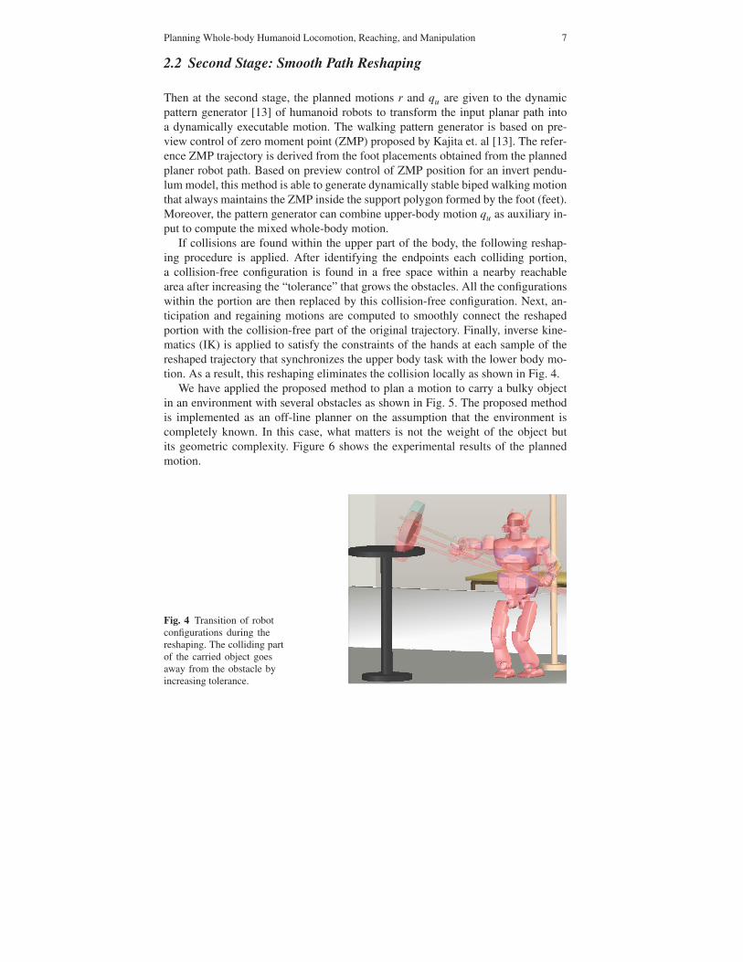
If collisions are found within the upper part of the body, the following reshap-ing procedure is applied. After identifying the endpoints each colliding portion,a collision-free configuration is found in a free space within a nearby reachablearea after increasing the “tolerance” that grows the obstacles. All the configurationswithin the portion are then replaced by this collision-free configuration. Next, an-ticipation and regaining motions are computed to smoothly connect the reshapedportion with the collision-free part of the original trajectory. Finally, inverse kine-matics (IK) is applied to satisfy the constraints of the hands at each sample of thereshaped trajectory that synchronizes the upper body task with the lower body mo-tion. As a result, this reshaping eliminates the collision locally as shown in Fig. 4.
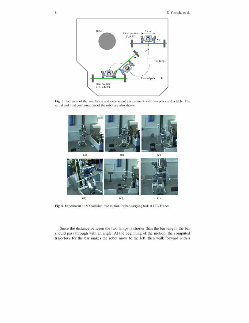
We have applied the proposed method to plan a motion to carry a bulky objectin an environment with several obstacles as shown in Fig. 5. The proposed methodis implemented as an off-line planner on the assumption that the environment iscompletely known. In this case, what matters is not the weight of the object butits geometric complexity. Figure 6 shows the experimental results of the plannedmotion.
Fig. 4 Transition of robotconfigurations during thereshaping. The colliding partof the carried object goesaway from the obstacle byincreasing tolerance.
8 E. Yoshida, et al.
�
�
67��1������ ������ �����50�50�5 �
1�����
8������� �����9,70�.,90�5 �
"������� �
Fig. 5 Top view of the simulation and experiment environment with two poles and a table. Theinitial and final configurations of the robot are also shown.
(a) (b) (c)
(d) (e) (f)
Fig. 6 Experiment of 3D collision-free motion for bar-carrying task at JRL-France
Since the distance between the two lamps is shorter than the bar length, the barshould pass through with an angle. At the beginning of the motion, the computedtrajectory for the bar makes the robot move to the left, then walk forward with a
Planning Whole-body Humanoid Locomotion, Reaching, and Manipulation 9
certain angle to path through the gap (Fig. 6a,b). Here the motion of the upper partof the robot is computed using a generalized inverse kinematics and the chest ismoved consequently to complete both tasks.
This example also shows that the complete 3D geometry of the object has beenconsidered in the collision-detection and path planning procedure and no boundingbox has been used (see Fig. 6d) where the concave part of the disk and the bar isclose to the lamp. The complete trajectory execution time is around 28 sec.
3 Reaching: Generalized Inverse Kinematic Approach
We here address the problem of how to re-position the humanoid body when per-forming reaching or grasping tasks for a target far away. The proposed methodis based on reshaping the support polygon of the humanoid robot to increase itsworkarea by coupling generalized inverse kinematics and dynamic walking patterngenerator [35]. While using inverse kinematics, the global motion is guaranteed tobe dynamically stable. Such a property is a direct consequence of ZMP control pro-vided by the pattern generator we use.
The generation of whole-body dynamic motion is closely related to motion plan-ning. Whereas the motion planning takes charge of global plan from initial to goalconfigurations, a whole-body motion generation concerns how to make valid localmotions by taking account of several constraints. So it is important in order to cre-ate feasible dynamic trajectories from motions that have been provided by the globalmotion planner.
Khatib and his colleagues have been working on dynamic motion generation forhumanoid robots by using task specification in operational space approach [27]. Intheir work a hierarchical controller synthesizes whole-body motion based on prior-itized behavioral primitives including postures and other tasks in a reactive manner.Kajita et al. proposed a “resolved momentum control” to achieve specified momen-tum by whole-body motion [14]. Mansard et al. [24] proposed a task sequencingscheme to achieve several tasks including walking and reaching at the same time.
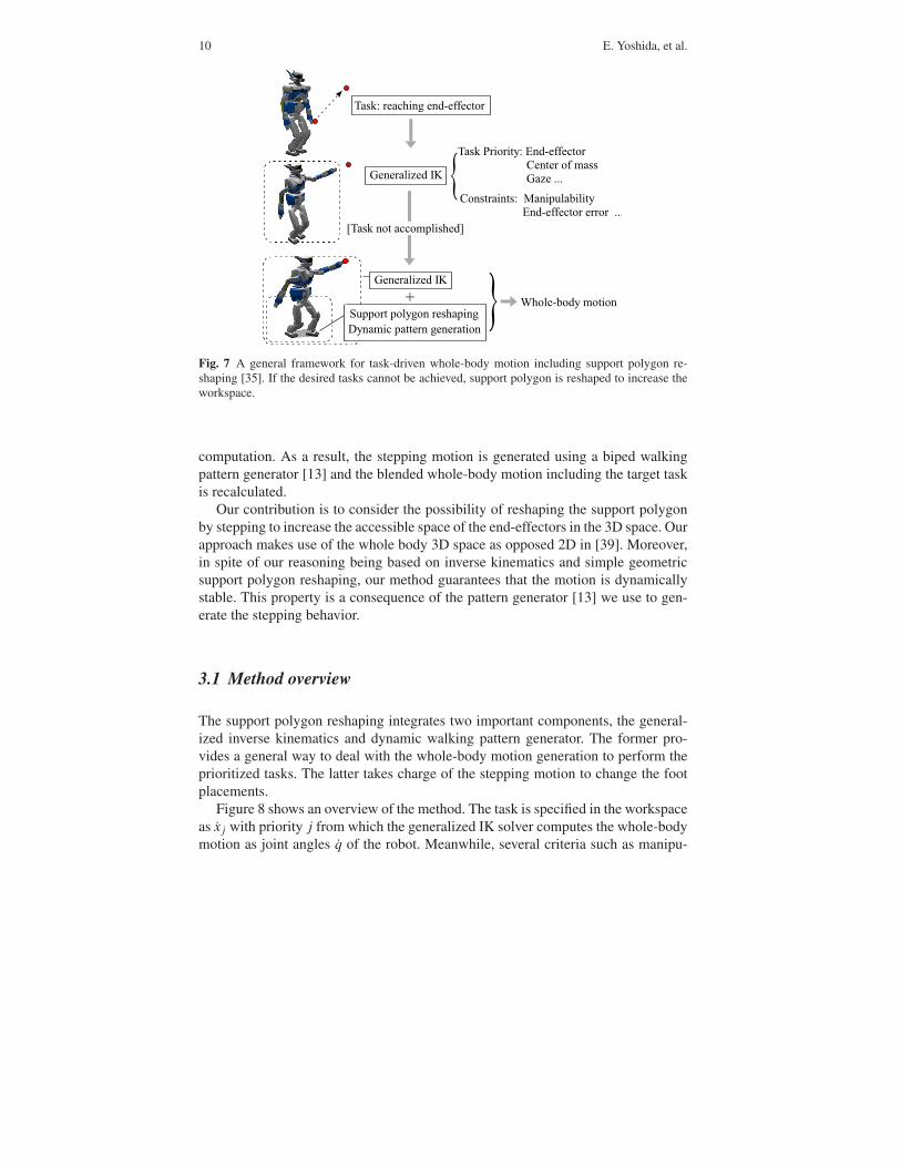
Figure 7 illustrates the proposed motion generation framework with an exampleof a reaching task [35]. Priorities are given to the target task as well as to other taskssuch as the position of center of mass (CoM). We employ generalized inverse kine-matics to generate a whole-body motion for those tasks based on the given priorities[25]. During the motion, several constraints are monitored which are expressed bysuch measures as manipulability for whole-body, end-effector errors from target, orjoint limits.
If the task cannot be achieved because those monitored constraints are not satis-fied, a reshaping planner of support polygon is activated automatically to increaseaccessible space of the robot, keeping the inverse kinematics working to achievethe tasks. The reshaping is performed based on geometric planning to deform thesupport polygon in the direction required by the specified task. Thanks to the usageof free-floating base, the changes in support phase can be easily integrated in the
10 E. Yoshida, et al.
1��!:�������������%����� ��
�������#����)
1��!�"����� &:�4��%����� ������������� ��������������������#��,,,
���� ���� �:����������� &���� �����4��%����� ����������,,,
���� ��&������������
;1��!��� �����������<
�������#����)
� $���%���&��� ���
�&������� ���������� ���
Fig. 7 A general framework for task-driven whole-body motion including support polygon re-shaping [35]. If the desired tasks cannot be achieved, support polygon is reshaped to increase theworkspace.
computation. As a result, the stepping motion is generated using a biped walkingpattern generator [13] and the blended whole-body motion including the target taskis recalculated.
Our contribution is to consider the possibility of reshaping the support polygonby stepping to increase the accessible space of the end-effectors in the 3D space. Ourapproach makes use of the whole body 3D space as opposed 2D in [39]. Moreover,in spite of our reasoning being based on inverse kinematics and simple geometricsupport polygon reshaping, our method guarantees that the motion is dynamicallystable. This property is a consequence of the pattern generator [13] we use to gen-erate the stepping behavior.
3.1 Method overview
The support polygon reshaping integrates two important components, the general-ized inverse kinematics and dynamic walking pattern generator. The former pro-vides a general way to deal with the whole-body motion generation to perform theprioritized tasks. The latter takes charge of the stepping motion to change the footplacements.
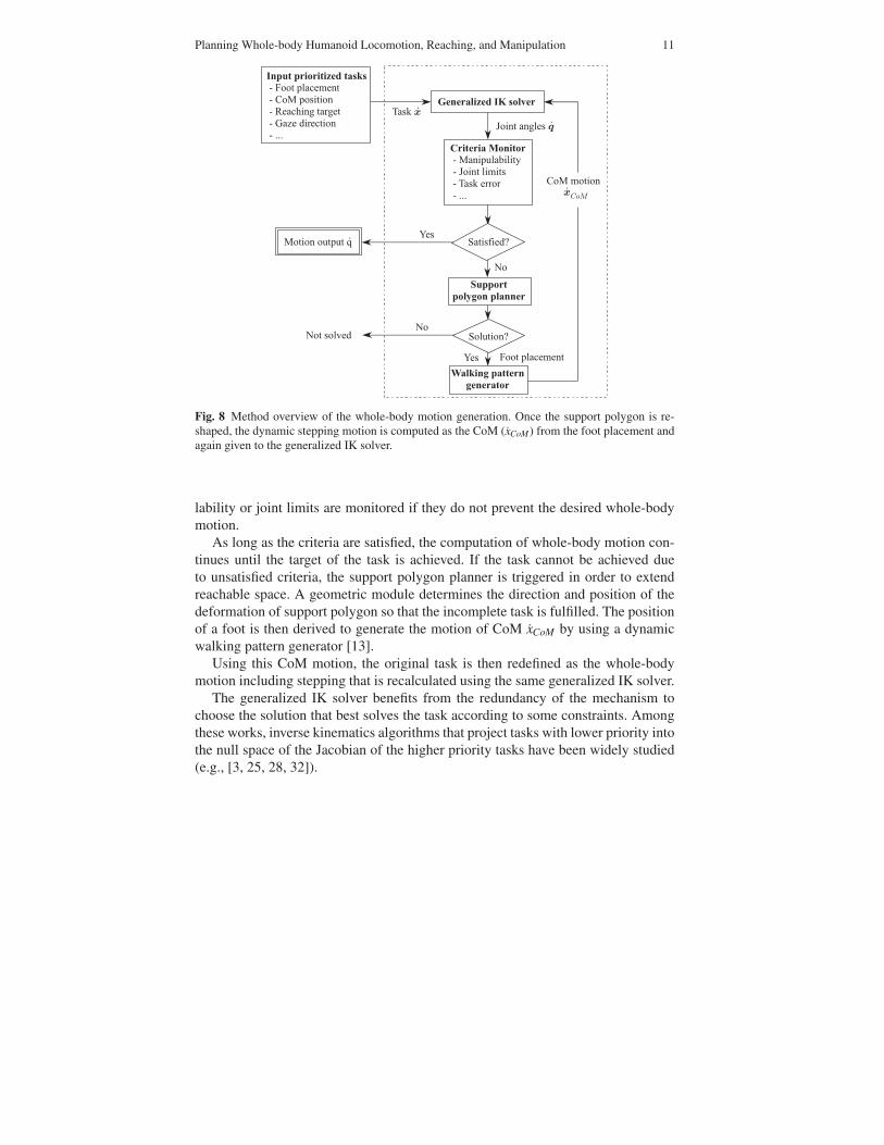
Figure 8 shows an overview of the method. The task is specified in the workspaceas x j with priority j from which the generalized IK solver computes the whole-bodymotion as joint angles q of the robot. Meanwhile, several criteria such as manipu-
Planning Whole-body Humanoid Locomotion, Reaching, and Manipulation 11
"�������#���$����%���
!�����������������%���������� &��%�/��� ���� ���%�1��!��������%�,,,�
���������������
���������
1��!��,
/��� ��������,
=�
&�������
���������������
$�������������#�������%�8�� ������� ��%�������� �����%���������� ���� ��%���#������� �����%�,,,�
�� ������2
��� ���2
>��
=�=� ���*��
�� ������ � �?�,
>�� 8�� �������
������ ����,����
�
Fig. 8 Method overview of the whole-body motion generation. Once the support polygon is re-shaped, the dynamic stepping motion is computed as the CoM (xCoM) from the foot placement andagain given to the generalized IK solver.
lability or joint limits are monitored if they do not prevent the desired whole-bodymotion.
As long as the criteria are satisfied, the computation of whole-body motion con-tinues until the target of the task is achieved. If the task cannot be achieved dueto unsatisfied criteria, the support polygon planner is triggered in order to extendreachable space. A geometric module determines the direction and position of thedeformation of support polygon so that the incomplete task is fulfilled. The positionof a foot is then derived to generate the motion of CoM xCoM by using a dynamicwalking pattern generator [13].
Using this CoM motion, the original task is then redefined as the whole-bodymotion including stepping that is recalculated using the same generalized IK solver.
The generalized IK solver benefits from the redundancy of the mechanism tochoose the solution that best solves the task according to some constraints. Amongthese works, inverse kinematics algorithms that project tasks with lower priority intothe null space of the Jacobian of the higher priority tasks have been widely studied(e.g., [3, 25, 28, 32]).
12 E. Yoshida, et al.
3.2 Generalized inverse kinematics for whole-body motion
3.2.1 Inverse Kinematics for Prioritized Tasks
Let us consider a task x j with priority j in the workspace and the relationship be-tween the joint angle velocity q is described using Jacobian matrix, like x j = J jq.For the tasks with the first priority, using pseudoinverse J#
1, the joint angles thatachieves the task is given:
q1 = J#1x1 +(In − J#
1J1)y1 (1)
where y1, n and In are an arbitrary vector, the number of the joints and identitymatrix of dimension n respectively.
For the task with second priority x2, the joint velocities q2 is calculated as follows[25]:
q2 = q1 + J#2(x2 − J2q1)+(In − J#
1J1)(In − J#2J2)y2
where J2 ≡ J2(In − J#1J1) (2)
where y2 is an arbitrary vector of dimension n. It can be extended to the task of jth
( j ≥ 2) priority in the following formula [3, 28].
q j = q j−1 + J#j(x j − J jq j−1)+N jy j (3)
N j ≡ N j−1(In − J#j J j), J j ≡ J j(In − J#
j−1J j−1)
3.2.2 Monitoring Task Execution Criteria
While the motion is being computed by the generalized IK, several properties aremonitored.
One of the important measures is the manipulability [40] defined as:
w ≡√
det{JJT} (4)
This measure is continuously tracked during the motion generation as well as otherssuch as joint angle limits or end-effector errors from the target. If it becomes belowa certain value, it means that it is difficult to achieve the task.
Joint limit constraints can be taken into account by introducing a selection diag-onal matrix S = diag{S1, . . .Sn} (Si = 0 or 1 ) to be multiplied to Jacobian to selectthe activated joints if the corresponding joint reaches a limit angle. The selectionmatrix is In if all the joints are used to achieve the task.
As shown in Figure 8, when one or more monitored measures go out of the admis-sible range to prevent the task from being achieved, the support polygon reshapingis launched to extend the accessible space as detailed next.
Planning Whole-body Humanoid Locomotion, Reaching, and Manipulation 13
3.2.3 Support polygon Reshaping
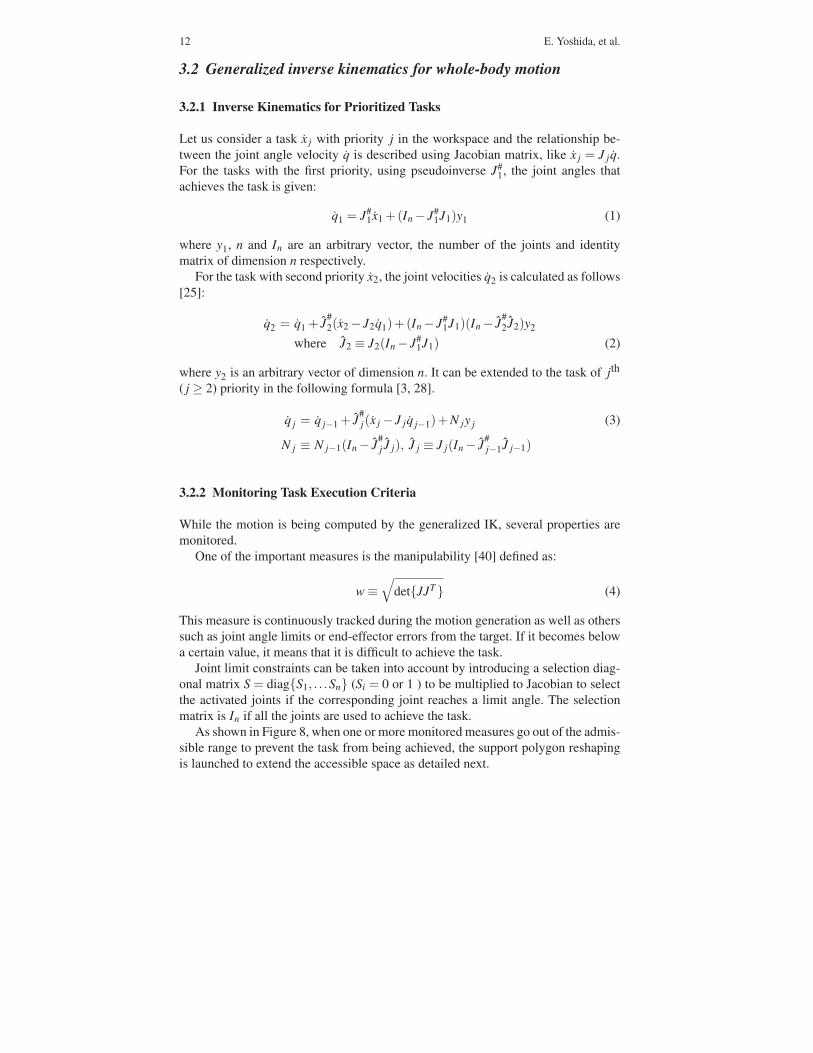
Figure 9 shows the proposed support polygon reshaping scheme. This simple algo-rithm allows the humanoid robot to make a step motion, keeping a large margin ofaccessible area for the task by facing the upper body to the target direction.
Then the CoM motion xCoM is computed from the new foot position by the walk-ing pattern generator based on the preview control of ZMP [13]. The basic idea is tocalculate the CoM motion by anticipating the desired future ZMP positions derivedfrom the footsteps.
Finally the original task is redefined as another problem of whole-body task us-ing this newly generated CoM motion with an additional task of CoM, which isrepresented by CoM Jacobian [29]. The same generalized IK solver framework isused to incorporate the motion required for the task and the stepping motion in thewhole-body level.
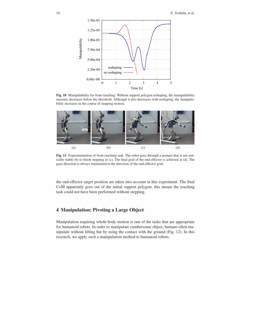
The manipulability measure of the arm during the forward reaching task is pro-vided in Fig. 10. Without reshaping, the arm approaches singular configurationwhere the manipulability becomes lower than the threshold at 2.3[s] and the com-putation keeping the same support polygon is discarded. The reshaping starts at thismoment to recalculate the overall whole-body motion including stepping motion.We can see the manipulability regains higher value at the final position.
3.3 Results
We have conducted experiments of the generated motion using a humanoid plat-form HRP-2 for front and sideways reaching tasks that requires stepping as shownin Fig 11. As can be seen, the robot successfully performed the desired reachingtask through whole-body motion that unifies reaching task and stepping motion bykeeping dynamic balance. Note that the tasks of keeping gaze direction towards
1���� ���� ���
"���������� ������� �����
�
φ�@��
=� ���� �������
�������� ���� �
����� � ����φ�
φ @�5
���� ��&���
��� ��
�������
Fig. 9 Support polygon reshaping method
14 E. Yoshida, et al.
��5,55��55
��.,75�%5A
��7,55�%5A
��6,75�%5A
��9,55�%5B
��9,.7�%5B
��9,75�%5B
�5 �9 �. �B �A �7
1����;�<
��������
�����������
��������� &
Fig. 10 Manipulability for front reaching. Without support polygon reshaping, the manipulabilitymeasure decreases below the threshold. Although it also decreases with reshaping, the manipula-bility increases in the course of stepping motion.
�1���� �
(a) (b) (c) (d)
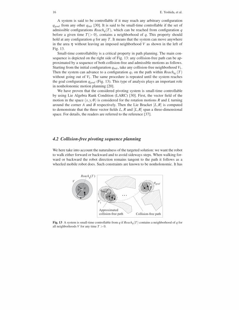
Fig. 11 Experimentation of front reaching task. The robot goes through a posture that is not stat-ically stable (b) to finish stepping in (c). The final goal of the end effector is achieved at (d). Thegaze direction is always maintained in the direction of the end-effector goal.
the end-effector target position are taken into account in this experiment. The finalCoM apparently goes out of the initial support polygon: this means the reachingtask could not have been performed without stepping.
4 Manipulation: Pivoting a Large Object
Manipulation requiring whole-body motion is one of the tasks that are appropriatefor humanoid robots. In order to manipulate cumbersome object, humans often ma-nipulate without lifting but by using the contact with the ground (Fig. 12). In thisresearch, we apply such a manipulation method to humanoid robots.

Planning Whole-body Humanoid Locomotion, Reaching, and Manipulation 15
There are several task-specific whole-body motions that have been intensivelyinvestigated: pushing [12, 9, 31], and lifting [10], and pivoting [33, 37]. Currently,many researchers are intensively working to integrate those recent developmentswith global motion planner.
Among them, the pivoting manipulation has several advantages such as precisepositioning, stability and adaptability over other methods like pushing or lifting. Forthose reasons, pivoting based manipulation has potential of widening the capacityof manipulation of humanoid robots.
We introduce here a whole-body motion planner that allows a humanoid robotto autonomously plan a pivoting strategy that accounts for the various constraints:collision avoidance, legs-arms coordination and stability control.
The motion planning algorithm we propose consider a two-stage approach: a firstcollision-free path is computed, and then it is iteratively approximated by a sequenceof pivoting motions.
4.1 Pivoting and small-time controllability
The robot starts inclining the box to realize a single contact point between the boxand the floor. The contact point is a corner of the box. Then the robot performs arotation of the box around the vertical axis on that corner. Then it sets the objecthorizontally along the box edge. Such an edge is said to be the supporting edge. Wehere model the problem of 3D box pivoting as the problem of pivoting a 2D segmentaround its endpoints.
���� ��������
C
�
3� ��0���
�
�
�
�
θ(a) (b)
Fig. 12 Supporting edge and pivoting problem modeling. (a) The pivoting sequence is plannedusing rotation of the endpoints of this edge. (b) The 3D pivoting problem is reduced to how todisplace a line segment on vertices A or B.
16 E. Yoshida, et al.
A system is said to be controllable if it may reach any arbitrary configurationqgoal from any other qinit [30]. It is said to be small-time controllable if the set ofadmissible configurations Reachq(T ), which can be reached from configuration qbefore a given time T (> 0), contains a neighborhood of q. This property shouldhold at any configuration q for any T . It means that the system can move anywherein the area η without leaving an imposed neighborhood V as shown in the left ofFig. 13.
Small-time controllability is a critical property in path planning. The main con-sequence is depicted on the right side of Fig. 13: any collision-free path can be ap-proximated by a sequence of both collision-free and admissible motions as follows.Starting from the initial configuration qinit , take any collision-free neighborhood V1.Then the system can advance to a configuration q1 on the path within Reachq1(T )without going out of V1. The same procedure is repeated until the system reachesthe goal configuration qgoal (Fig. 13). This type of analysis plays an important rolein nonholonomic motion planning [20].
We have proven that the considered pivoting system is small-time controllableby using Lie Algebra Rank Condition (LARC) [30]. First, the vector field of themotion in the space (x,y,θ) is considered for the rotation motions R and L turningaround the corner A and B respectively. Then the Lie Bracket [L,R] is computedto demonstrate that the three vector fields L, R and [L,R] span a three-dimensionalspace. For details, the readers are referred to the reference [37].
4.2 Collision-free pivoting sequence planning
We here take into account the naturalness of the targeted solution: we want the robotto walk either forward or backward and to avoid sideways steps. When walking for-ward or backward the robot direction remains tangent to the path it follows as awheeled mobile robot does. Such constraints are known to be nonholonomic. It has
η
���� ����
9
�������%������ �
9
����
C��D��� ����������%������ �
Fig. 13 A system is small-time controllable from q if Reachq(T ) contains a neighborhood of q forall neighborhoods V for any time T > 0.
Planning Whole-body Humanoid Locomotion, Reaching, and Manipulation 17
been recently demonstrated that they account for the natural human locomotion [2].Our motion planning point of view then benefits from well experienced approachesin nonholonomic motion planning [4, 20, 22]. Among them we have chosen theprobabilistic sampling approach with a steering method computing Reeds and Sheppcurves [26], composed of arc of a circle and straight line segments. Reeds and Sheppcurves possess a geometric property accounting for small-time controllability, a crit-ical property for the planning method completeness.
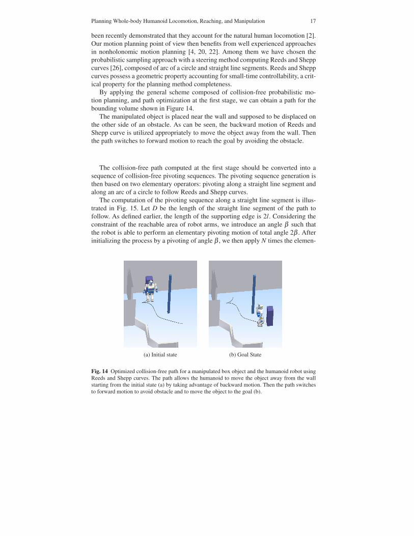
By applying the general scheme composed of collision-free probabilistic mo-tion planning, and path optimization at the first stage, we can obtain a path for thebounding volume shown in Figure 14.
The manipulated object is placed near the wall and supposed to be displaced onthe other side of an obstacle. As can be seen, the backward motion of Reeds andShepp curve is utilized appropriately to move the object away from the wall. Thenthe path switches to forward motion to reach the goal by avoiding the obstacle.
The collision-free path computed at the first stage should be converted into asequence of collision-free pivoting sequences. The pivoting sequence generation isthen based on two elementary operators: pivoting along a straight line segment andalong an arc of a circle to follow Reeds and Shepp curves.
The computation of the pivoting sequence along a straight line segment is illus-trated in Fig. 15. Let D be the length of the straight line segment of the path tofollow. As defined earlier, the length of the supporting edge is 2l. Considering theconstraint of the reachable area of robot arms, we introduce an angle β such thatthe robot is able to perform an elementary pivoting motion of total angle 2β . Afterinitializing the process by a pivoting of angle β , we then apply N times the elemen-
(a) Initial state (b) Goal State
Fig. 14 Optimized collision-free path for a manipulated box object and the humanoid robot usingReeds and Shepp curves. The path allows the humanoid to move the object away from the wallstarting from the initial state (a) by taking advantage of backward motion. Then the path switchesto forward motion to avoid obstacle and to move the object to the goal (b).

18 E. Yoshida, et al.
Fig. 15 Transforming astraight line segment pathinto a pivoting sequence. Thepivoting sequence is plannedusing rotation of the end-points of the supporting edge.During the regular sequence,rotations of same angles arerepeated before adjustmentsequence that positions theline segment at the endpoint.
��
β
.β
���������?�����C�E�� ��� ���?�����
�
tary pivoting motion of angle 2β , N being defined as the greater integer verifyingD > 2Nl sinβ . The same principle applies to the arcs of a circle.
We should notice that the rotation angle β may be tuned for obstacle avoidancepurpose. Indeed, the first stage of the algorithm provides a collision-free path thatguarantees collision-freeness for the sliding supporting edge. As this rotation angledecreases, the final swept volume of the generated pivoting sequence converges toinitial one swept by the supporting edge when sliding along the Reeds and Shepppath. This property accounts for the small-time controllability of the pivoting sys-tem we have considered in Section 4.1. The 3D collision detection can be done byestimating the swept volume of the object attached to the supporting edge duringthe rotational motion.
As a consequence, the two-stage strategy we have developed inherits from theprobabilistic completeness of the motion planner used at the first stage. The ap-proximation scheme by on pivoting sequence generation does not introduce anyincompleteness thanks to small-time controllability.
4.3 Whole-body motion generation and experiments
The Reeds and Shepp curve and the pivot sequence generation are implemented asproblem-specific steering methods shown in Fig. 1. After the pivoting sequence isgenerated, it should be realized by the humanoid robot by using its two arms. Thehumanoid motion should be generated in such a way that constraints like dynamicbalancing and arm manipulation motion are satisfied at the same time. Moreover,stepping motion should be added in order to continue the manipulation when nec-essary.
For this purpose we adopt the dynamic whole-body motion generation in Sec-tion 3. Since all the joints are involved to make those complicated combined mo-

Planning Whole-body Humanoid Locomotion, Reaching, and Manipulation 19
tions, we can expect better performance in the sense of reachable space than a func-tional decomposition utilized in [33].
The method is illustrated in Fig. 16. There is a motion manager that a whole-body motion manager receives the desired hand trajectories and keeps track of thecurrent robot configuration. Then it computes the trajectories or constraints that aresupplied to the generalized IK solver. The solver is also given trajectories of feet orCoM as well as their position and orientation constraints as prioritized tasks. Withthose inputs, the generalized IK solver computes the whole-body motion as jointangle trajectories.
When the pivoting rotation requires large horizontal displacement, a steppingmotion is planned at the same time of the hand motion. The stepping foot is deter-mined depending on the rotation direction. Then the new foot position is computedin such a way that the foot keeps its orientation in parallel with the base Reeds andShepp curves with an appropriate distance to the object. The same dynamic whole-body motion generator presented in Section 3 is applied to compute the coordinatedarm and foot-stepping motions.
We have conducted the experiments with the humanoid robot platform HRP-2 inthe environment shown in Fig. 14 for whole-body motion planning for pivoting of abox-shape object.
The execution time of the entire pivoting sequence is 281 seconds, which cor-responds to 56200 command outputs at the rate of 5ms for each of 30 joints. The
(��%���&������ ����$��� ������ � �����,,,�
,
$���%���&��� ������*��� � ���������#����)�
$���%���&��� �����������-����
��E�� ��&
/��� ��������� �
,
"�*� ������ ������?����� 3�E�� �
��� ���
3 �������� ���� �
� ������� ���
=��%� ������� ���
�������� ���� �,
���� ��E�� ��&�8�� � ��E�� ��&�
,
Fig. 16 Usage of generalized inverse kinematics utilized for whole-body motion for pivoting basedmanipulation.
20 E. Yoshida, et al.
computation time was 291.7 seconds with a PC of Intel Core2 Duo CPU at 2.13GHz,which is comparable to the actual task execution time.
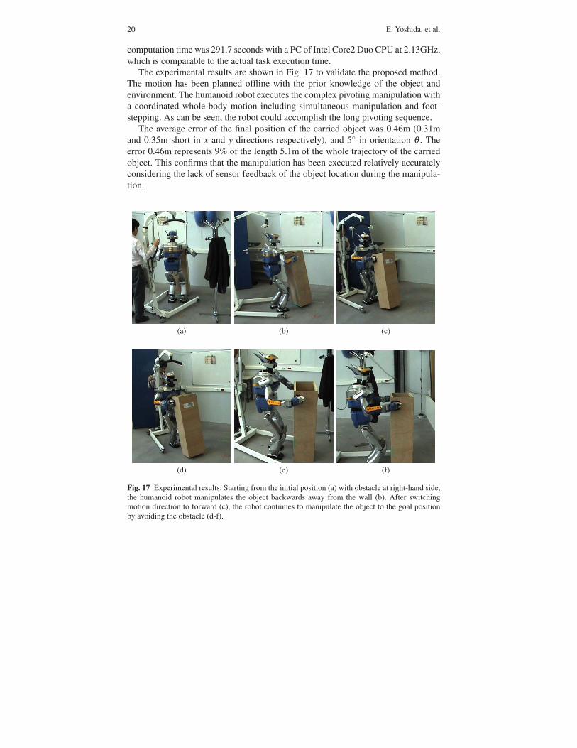
The experimental results are shown in Fig. 17 to validate the proposed method.The motion has been planned offline with the prior knowledge of the object andenvironment. The humanoid robot executes the complex pivoting manipulation witha coordinated whole-body motion including simultaneous manipulation and foot-stepping. As can be seen, the robot could accomplish the long pivoting sequence.
The average error of the final position of the carried object was 0.46m (0.31mand 0.35m short in x and y directions respectively), and 5◦ in orientation θ . Theerror 0.46m represents 9% of the length 5.1m of the whole trajectory of the carriedobject. This confirms that the manipulation has been executed relatively accuratelyconsidering the lack of sensor feedback of the object location during the manipula-tion.
(a) (b) (c)
(d) (e) (f)
Fig. 17 Experimental results. Starting from the initial position (a) with obstacle at right-hand side,the humanoid robot manipulates the object backwards away from the wall (b). After switchingmotion direction to forward (c), the robot continues to manipulate the object to the goal positionby avoiding the obstacle (d-f).
Planning Whole-body Humanoid Locomotion, Reaching, and Manipulation 21
4.4 Regrasp planning
So far we developed the whole-body manipulation method on the assumption thatthe robot can carry the object without changing the grasping points. However, whenthere are narrow spaces, the robot should sometimes release the object and hold itwith another position according to the situation.
We here provide a humanoid robot with more flexibility in whole-body pivotingmanipulation by including regrasp planning. The robot releases the object when itcannot go further towards the goal position and grasp it again to continue manipu-lation.
The difficulty resides in finding narrow passages for the robot and object togetherand in combining the paths with different grasping positions to plan a manipulationmotion to achieve the goal. We here address the regrasp planning problem for piv-oting manipulation through a roadmap-multiplexing approach [38].
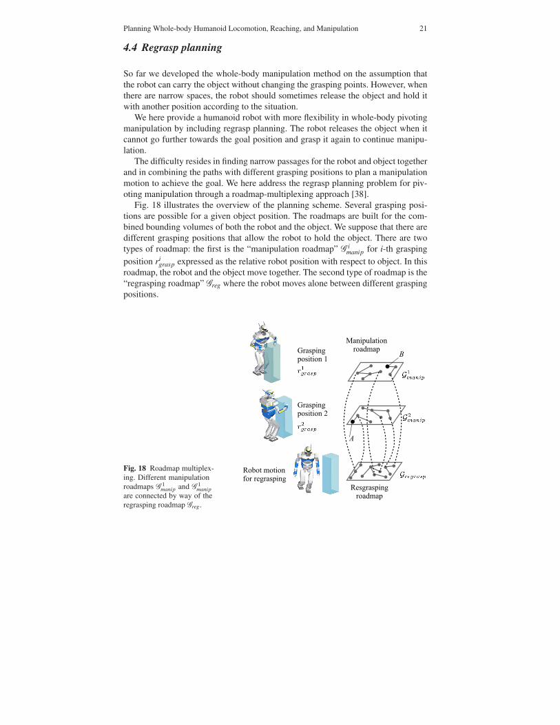
Fig. 18 illustrates the overview of the planning scheme. Several grasping posi-tions are possible for a given object position. The roadmaps are built for the com-bined bounding volumes of both the robot and the object. We suppose that there aredifferent grasping positions that allow the robot to hold the object. There are twotypes of roadmap: the first is the “manipulation roadmap” G i
manip for i-th graspingposition ri
grasp expressed as the relative robot position with respect to object. In thisroadmap, the robot and the object move together. The second type of roadmap is the“regrasping roadmap” Greg where the robot moves alone between different graspingpositions.
Fig. 18 Roadmap multiplex-ing. Different manipulationroadmaps G 1
manip and G 1manip
are connected by way of theregrasping roadmap Greg.

22 E. Yoshida, et al.
(a) Initial position (e)
(b) (f)
(c) (g)
(d) (h) Goal position
Fig. 19 Simulation result of regrasp planning. Starting from initial position (a), the humanoid robotmakes pivoting sequences (b) first puts the object to the entry of passage (c). It leaves the objectand walks freely by combining forward and sideways walking (d) to regrasp the object on theother side (e). Then the robot goes towards another narrow passage (f) and make another regraspsequence (g) to arrive at the goal (h).
As can be seen in the figure, manipulation roadmaps G 1manip and G 2
manip for dif-ferent grasping positions are interconnected via the regrasping roadmap Greg. For
Planning Whole-body Humanoid Locomotion, Reaching, and Manipulation 23
instance, the path from A to B is possible only by alternating the different graspingpositions.
Figure 19 shows the result of regrasp planning. The humanoid robot HRP-2should carry a box-share object from the initial position (Fig. 19a) to its goal(Fig. 19h). The humanoid robot displaces the object at the entry of a narrow pas-sage (Fig. 19b, c). Then it releases the object and walk to the other side of the wall(Fig. 19d). By combining backward and forward manipulation, the humanoid goesto another narrow passage (Fig. 19e, f). After another regrasping, the object is car-ried to the goal position (Fig. 19g, h).
5 Motion in Real World: Integrating with Perception
In this section the presented motion planning methods are integrated with percep-tion, principally vision, to make actions in the real world. This integration allows therobot to execute such commands as “go to the yellow table” and “take the orangeball.”
5.1 Object recognition and localization
The HRP-2 robot is equipped with two pairs of firewire digital color cameras, con-figured as two independent stereo-vision camera pairs. We here utilize standard stateof the art components to implement a simple function of object recognition and lo-calization.
For the detection, the model of the objects to be detected are previously learnedusing two dimensional histogram in the {Hue,Saturation} color space by taking asample image with a color space.
The object detection is performed by back projecting the object histogram ontoa video image. The back projection image is obtained by replacing each {H,S,V}pixel value by the corresponding value in the histogram, leading to a probabilityimage where each pixel value is the probability of that pixel to belong to the objectmodel. The Continuously Adaptive Mean SHIFT CamShift algorithm then locatesthe object center and orientation in the back projection image.
A stereo-vision algorithm by pixel correlation is applied on the stereo imagepairs, and produces a dense three dimensional image of the current scene. Eventhough pixel correlation is known to give poor results in indoor environments, theobjects to localize are sufficiently textured so that precise enough 3D points can beobtained in the vicinity of the objects.

24 E. Yoshida, et al.
Detection of the object
Detection of the table
Fig. 20 Table and Object detection. Left images show the HSV image and right images are the backprojection of the table color model in the source image. Rectangle is the result of the execution ofthe CAMSHIFT algorithm on the back projection image.
5.2 Coupling the motion planner with perception
The motion planners presented in previous sections are integrated with the visionsystem so that the robot can execute a task composed of navigation and object grasp-ing.
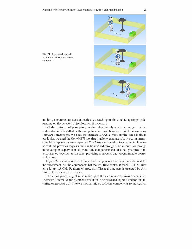
For navigation, we apply the same type of two-stage motion planner for navi-gation planning presented in Section 2. At the first stage, a collision-free smoothlocomotion path is calculated for the approximated bounding box. It is desirable forthe robot to walk forward in order to look at the object and to take it. This preferencecan be modeled as a nonholonomic constraint in the same way as in Section 2 and 4and we can benefit from well-developed planning method of a smooth path for car-like robot [20]. Then the path is transformed into dynamic humanoid locomotion atthe second stage by applying the dynamic walking patter generator in the same wayas in Section 2. This navigation planner allows the humanoid robot to go in front ofthe visually located colored table several meters away by avoiding known obstaclesas shown in Figure 21.
Finally, the whole-body motion generator presented in Section 3 is used for thegrasping task. Given the object location from the vision system, the whole-body
Planning Whole-body Humanoid Locomotion, Reaching, and Manipulation 25
Fig. 21 A planned smoothwalking trajectory to a targetposition
motion generator computes automatically a reaching motion, including stepping de-pending on the detected object location if necessary.
All the software of perception, motion planning, dynamic motion generation,and controller is installed on the computers on board. In order to build the necessarysoftware components, we used the standard LAAS control architectures tools. Inparticular, we used the GenoM [7] tool that is able to generate robotics components.GenoM components can encapsulate C or C++ source code into an executable com-ponent that provides requests that can be invoked through simple scripts or throughmore complex supervision software. The components can also be dynamically in-terconnected together at run-time, providing a modular and programmable controlarchitecture.
Figure 22 shows a subset of important components that have been defined forthe experiment. All the components but the real-time control (OpenHRP [15]) runson a Linux 1.8 GHz Pentium-M processor. The real-time part is operated by Art-Linux [1] on a similar hardware.
The vision processing chain is made up of three components: image acquisition(camera), stereo-vision by pixel correlation (stereo) and object detection and lo-calization (hueblob). The two motion-related software components for navigation

26 E. Yoshida, et al.
Fig. 22 Software components running onboard the robot.
and whole-body motion generation are implemented as components walk and gikrespectively. Finally, an interface component (hrp2) makes the connection with theOpenHRP software and bridges the CORBA communication bus of OpenHRP to theGenoM communication bus (Posix Real-Time communication library on Figure 22).
All these components define requests that can be invoked by a human operator,by supervision software or by the natural language processing system.
5.3 Experiments
We have conducted experiments to validate the integrated system. The humanoidrobot is given a task to take a colored ball and put it at another place. The task is de-composed into several generic action commands, such as detection and localizationof a learned object, locomotion to a location, and hand reaching to a position in 3D,with other simple tasks like turning on the spot and gripper opening and closing.
A simple supervision system that can invoke the actions with scripts is utilizedto manage the robot behavior easily. Each action can report failures (e.g. failure ingrasping an object). It is thus possible to implement error recovery strategies byanalyzing the reports of the actions. In the following experiment, each action isassociated with a vocal command to allow the user to give a sequence of commandsto the robot in an interactive manner.
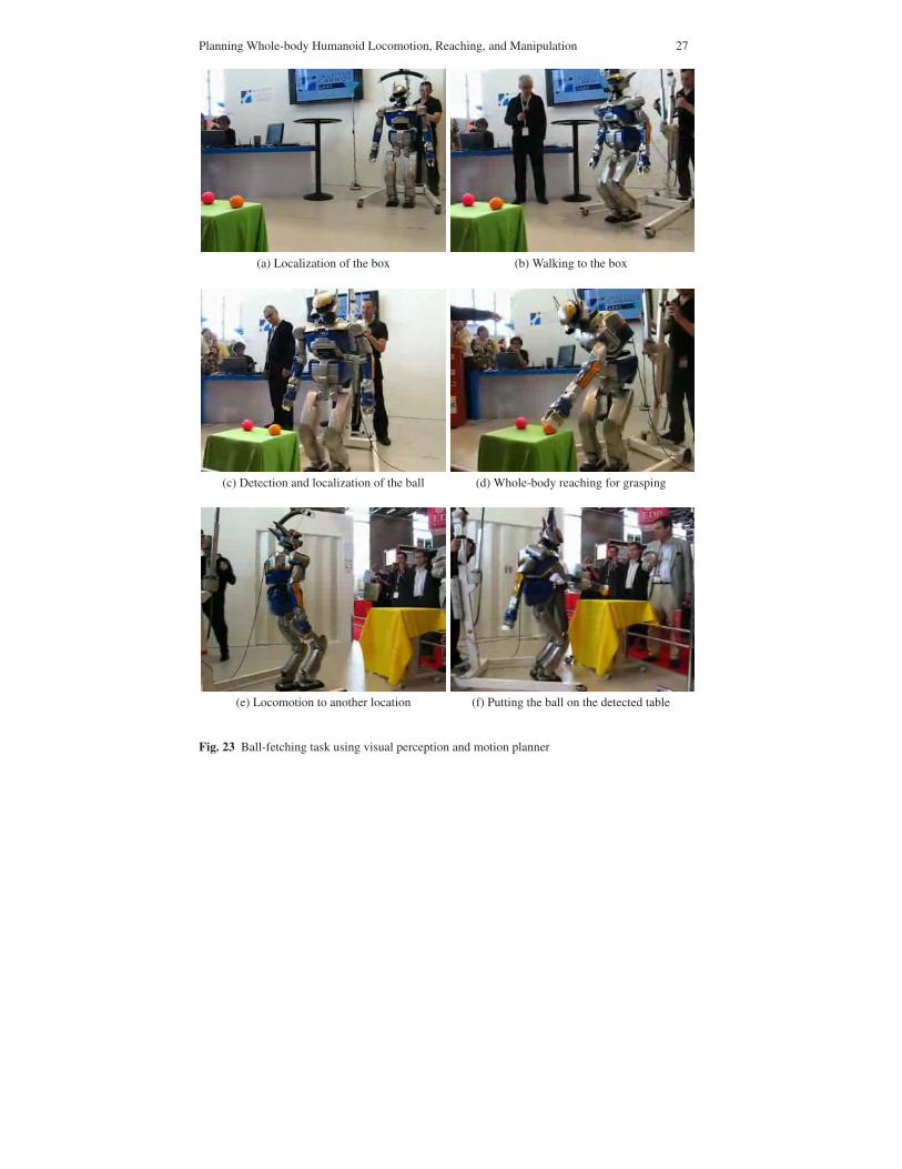
Figure 23 shows snapshots of experiments. Since the ball is too far away to bedetected with camera at the initial position, the humanoid robot first localizes thegreen box on which the balls are placed (Fig 23a). The robot walks with a smoothtrajectory in front of the box (Fig 23b) and localizes precisely the colored ball tograsp (Fig 23c). Then the whole-body reaching motion is executed to grasp the ball
Planning Whole-body Humanoid Locomotion, Reaching, and Manipulation 27
(a) Localization of the box (b) Walking to the box
(c) Detection and localization of the ball (d) Whole-body reaching for grasping
(e) Locomotion to another location (f) Putting the ball on the detected table
Fig. 23 Ball-fetching task using visual perception and motion planner
28 E. Yoshida, et al.
(Fig 23d). After turning, the robot is told to detect a colored table and walks towardsit always with a smooth trajectory (Fig 23e). Finally it puts the ball on the table againwith whole-body motion (Fig 23f).
This experiment was conducted more than ten times in an exposition in frontof the public using vocal interaction by a human operator. Since the location ofthe robots and objects are different at every demonstration, it happened that therobot failed to grasp with unexpected disturbances or localization errors. However,the task could be executed again successfully thanks to the generality of the actioncommands, by just repeating the same action command. As a result, all the demoswere successful including those retries. This validates the reliability of the proposedmotion planner, the integrated perception system and also the robustness of taskexecution framework.
6 Conclusion
In this article, we have presented research results on whole-body motion planningfrom several aspects: collision-free locomotion with upper-body motion, whole-body reaching and manipulation. To cope with the redundancy and underactuationof humanoid robots, we have integrated probabilistic motion planning and dynamicmotion generation of humanoid robots. The results have been validated by the hu-manoid robot platform HRP-2.
In our future developments, we keep pursuing our aim of improving the auton-omy of the humanoid robots by increasing the variety of their motions and thus byenriching the possible behaviors. Besides this motion autonomy, we will also haveto address the reactivity in the real environments. In the last part of this article wedemonstrated an example of closed perception-behavior loop. However, fast andprecise environment recognition as well as reactive motion planning scheme stillneeds to be investigated for the humanoid robot to adapt to more complex situa-tions. We will address those problems in our future work.
References
1. ART linux. http://sourceforge.net/projects/art-linux2. Arechavaleta, G., Laumond, J.P., Hicheur, H., Berthoz, A.: An optimality principle governing
human walking. IEEE Trans. on Robotics 24(1), 5 – 14 (2008)3. Baerlocher, P., Boulic, R.: An inverse kinematics architecture enforcing and arbitrary number
of strict priority levels. The Visual Computer 20, 402–417 (2004)4. Choset, H., Lynch, K., Hutchinson, S., Kantor, G., Burgard, W., Kavraki, L., Thrun, S.: Prin-
ciples of Robot Motion: Theory, Algorithms, and Implementation. MIT Press (2006)5. Dubins, L.E.: On curves of minimal length with a constraint on average curvature and pre-
scribed initial and terminal positions and tangents. American Journal of Mathematics 79,497–516 (1957)
Planning Whole-body Humanoid Locomotion, Reaching, and Manipulation 29
6. Esteves, C., Arechavaleta, G., Pettre, J., Laumond, J.P.: Animation planning for virtual char-acters cooperation. ACM Trans. on Graphics 25(2), 319–339 (2006)
7. Fleury, S., Herrb, M., Chatila, R.: Genom: a tool for the specification and the implementationof operating modules in a distributed robot architecture. In: Proc. 1997 IEEE Int. Conf. onIntelligent Robots and Systems, pp. 842 – 849 (1997)
8. Gleicher, M.: Comparing constraint-based motion editing method. Graphical Models 63, 107–134 (2001)
9. Harada, H., Kajita, S., Kanehiro, F., Fujiwara, K., Kaneko, K., Yokoi, K., Hirukawa, H.: Real-time planning of humanoid robot’s gait for force controlled manipulation. In: Proc. 2004 IEEEInt. Conf. on Robotics and Automation, pp. 616–622 (2004)
10. Harada, H., Kajita, S., Saito, H., Morisawa, M., Kanehiro, F., Fujiwara, K., Kaneko, K.,Hirukawa, H.: A humanoid robot carrying a heavy object. In: Proc. 2005 IEEE Int. Conf.on Robotics and Automation, pp. 1712–1717 (2005)
11. Hsu, D., Latombe, J.C., Sorkin, S.: Placing a robot manipulator amid obstacles for optimizedexecution. In: Proc. 1999 Int. Symp. on Assembly and Task Planning, pp. 280–285 (1999)
12. Hwang, Y., Konno, A., Uchiyama, M.: Whole body cooperative tasks and static stability eval-uations for a humanoid robot. In: Proc. 2003 IEEE/RSJ Int. Conf. on Intelligent Robots andSystems, pp. 1901–1906 (2003)
13. Kajita, S., Kanehiro, F., Kaneko, K., Fujiwara, K., Harada, K., Yokoi, K., Hirukawa, H.: Bipedwalking pattern generation by using preview control of zero-moment point. In: Proc. 2003IEEE Int. Conf. on Robotics and Automation, pp. 1620–1626 (2003)
14. Kajita, S., Kanehiro, F., Kaneko, K., Fujiwara, K., Harada, K., Yokoi, K., Hirukawa, H.: Re-solved momentum control: Humanoid motion planning based on the linear and angular mo-mentum. In: Proc. 2993 IEEE/RSJ Int. Conf. on Intelligent Robots and Systems, pp. 1644–1650 (2003)
15. Kanehiro, F., Hirukawa, H., Kajita, S.: OpenHRP: Open architecture humanoid robotics plat-form. Int. J. of Robotics Research 23(2), 155–165 (2004)
16. Kaneko, K., Kanehiro, F., Kajita, S., Hirukawa, H., Kawasaki, T., M. Hirata, K.A., Isozumi,T.: The humanoid robot HRP-2. In: Proc. 2004 IEEE Int. Conf. on Robotics and Automation,pp. 1083–1090 (2004)
17. Kavraki, L., Svestka, P., Latombe, J.C., Overmars, M.: Probabilistic roadmaps for path plan-ning in high-dimensional configuration spaces. IEEE Trans. on Robotics and Automation12(4), 566–580 (1996)
18. Kuffner, J.: Motion planning with dynamics. Physiqual (1998)19. Kuffner, J., Kagami, S., Nishiwaki, K., Inaba, M., , Inoue: Dynamically-stable motion plan-
ning for humanoid robots. Autonomous Robots 12(1), 105–118 (2002)20. Laumond, J.P. (ed.): Robot Motion Planning and Control, Lectures Notes in Control and In-
formation Sciences, vol. 229. Springer (1998)21. Laumond, J.P.: Kineo cam: a success story of motion planning algorithms. IEEE Robotics &
Automation Magazine 13(2), 90–93 (2006)22. LaValle, S.: Planning Algorithm. Cambridge University Press (2006)23. LaValle, S., Kuffner, J.: Rapidly-exploring random trees: Progress and prospects. In: K.M.
Lynch, D. Rus (eds.) Algorithmic and Computational Robotics: New Directions, pp. 293–308.A K Peters (2001)
24. Mansard, N., Stasse, O., Chaumette, F., Yokoi, K.: Visually-guided grasping while walking ona humanoid robot. In: Proc. 2007 IEEE Int. Conf. on Robotics and Automation, pp. 3042–3047(2007)
25. Nakamura, Y.: Advanced Robotics: Redundancy and Optimization. Addison-Wesley Long-man Publishing, Boston (1991)
26. Reeds, J.A., Shepp, R.A.: Optimal paths for a car that goes both forwards and backwards.Pacific Journal of Mathematics 145(2), 367–393 (1990)
27. Sentis, L., Khatib, O.: Synthesis of whole-body behaviors through hierarchical control of be-havioral primitives. Int. J. of Humanoid Robotics 2(4), 505–518 (2005)

30 E. Yoshida, et al.
28. Siciliano, B., Slotine, J.J.E.: A general framework for managing multiple tasks in highly re-dundant robotic systems. In: Proc. IEEE Int. Conf. on Advanced Robotics, pp. 1211–1216(1991)
29. Sugihara, T., Nakamura, Y., Inoue, H.: Realtime humanoid motion generation through zmpmanipulation based on inverted pendulum control. In: Proc. 2002 IEEE Int. Conf. on Roboticsand Automation, pp. 1404–1409 (2002)
30. Sussmann, H.: Lie brackets, real analyticity and geometric control. In: R. Brockett, R. Mill-man, H. Sussmann (eds.) Differential Geometric Control Theory, Progress in Mathematics,vol. 27, pp. 1–116. Michigan Technological University, Birkhauser (1982)
31. Takubo, T., Inoue, K., Sakata, K., Mae, Y., Arai, T.: Mobile manipulation of humanoid robots– control method for com position with external force –. In: Proc. 2004 IEEE/RSJ Int. Conf.on Intelligent Robots and Systems, pp. 1180–1185 (2004)
32. Yamane, K., Nakamura, Y.: Natural motion animation through constraining and deconstrain-ing at will. IEEE Trans. on Visualization and Computer Graphics 3(9), 352–360 (2003)
33. Yoshida, E., Blazevic, P., Hugel, V., Yokoi, K., Harada, K.: Pivoting a large object: whole-bodymanipulation by a humanoid robot. J. of Applied Bionics and Biomechanics 3(3), 227–235(2006)
34. Yoshida, E., Esteves, C., Belousov, I., Laumond, J.P., Sakaguchi, T., Yokoi, K.: Planning 3Dcollision-free dynamic robotic motion through iterative reshaping. IEEE Trans. on Robotics24(5), 1186–1198 (2008)
35. Yoshida, E., Kanoun, O., Esteves, C., Laumond, J.P., Yokoi, K.: Task-driven support polygonreshaping for humanoids. In: Proc. 2006 IEEE-RAS Int. Conf. on Humanoid Robots, pp.827–832 (2006)
36. Yoshida, E., Mallet, A., Lamiraux, F., Kanoun, O., Stasse, O., Poirier, M., Dominey, P.F.,Laumond, J.P., Yokoi, K.: “give me the purple ball” – he said to HRP-2 N.14. In: Proc. 2006IEEE-RAS Int. Conf. on Humanoid Robots (2007)
37. Yoshida, E., Poirier, M., Laumond, J.P., Alami, R., Yokoi, K.: Pivoting based manipulationby humanoids: a controllability analysis. In: Proc. 2007 IEEE/RSJ Int. Conf. on IntelligentRobots and Systems, pp. 1130–1135 (2007)
38. Yoshida, E., Poirier, M., Laumond, J.P., Kanoun, O., Lamiraux, F., Alami, R., Yokoi, K.:Regrasp planning for pivoting manipulation by a humanoid robot. In: Proc. 2009 IEEE Int.Conf. on Robotics and Automation (2009). To appear
39. Yoshida, H., Inoue, K., Arai, T., , Mae, Y.: Mobile manipulation of humanoid robots - a methodof adjusting leg motion for improvement of arm’s manipulability. In: Proc. 2001 IEEE/ASMEInt. Conf. on Advanced Intelligent Mechatronics, pp. 266–271 (2001)
40. Yoshikawa, T.: Manipulability of robotic mechanisms. Int. J. Robotics Research 4(2), 3–9(1985)