planning your autoclave installation · autoclave from sucking water back from the drain as it...
TRANSCRIPT

This document is the intellectual property of Priorclave Ltd, it is company confidential and must not be copied in full or part, or communicated to any other party.
H:\Technical\MANUALS\Planning your autoclave installation V11.docx Issue 11 11/01/2019 Page 1 of 17
Planning your autoclave installation
Introduction
This document has been compiled by Priorclave to assist in the planning, siting and installation of your autoclave. It is primarily intended for use by Architects and building services professionals during new build and major refurbishment situations where the location of and provision of services to the autoclave can be considered anew.
On occasions, this guide will be supplied directly to the purchaser or user of the autoclave, in such circumstances the requirements detailed herein may make the autoclave installation seem a daunting task. Please feel free to contact Priorclave technical staff at any time for assistance.
In cases of the replacement of existing autoclaves where the location is pre-determined it may prove difficult to provide for all of the requirements contained herein. In all cases Priorclave technical staff will be pleased to discuss individual installations. It should be noted however that the location and services for an existing autoclave may well prove inadequate for a new unit due to changes in specification, and legislation etc. since the commissioning of the old unit.
This document is the intellectual property of Priorclave Ltd, it is company confidential and must not be copied in full or part, or communicated to any other party.
H:\Technical\MANUALS\Planning your autoclave installation V11.docx Issue 11 11/01/2019 Page 2 of 17
Contents Introduction ........................................................................................................................................... 1
Contents ................................................................................................................................................. 2
Section 1 General considerations for the Autoclave Location .................................................................. 3
1.1 Maintenance access: ................................................................................................................................ 3
Diagram 1 - Plan view of a typical Autoclave Installation – Against a wall: .................................................. 3
1.2 Heat emission:.......................................................................................................................................... 3
1.3 Steam emission: ....................................................................................................................................... 4
1.4 Floor loading: ........................................................................................................................................... 4
1.5 Extractor Hoods: ...................................................................................................................................... 4
Section 2: Autoclave Connection to site Utilities ..................................................................................... 5
2.1 Drainage and exhaust gas ventilation - General: ..................................................................................... 5
Diagram 2 - REAR view of a typical autoclave connection requirement: ...................................................... 6
Diagram 3 - Single Autoclave Installation: ..................................................................................................... 7
Diagram 4 - Multiple autoclaves in a single location:.................................................................................... 7
Diagram 5 - Cold drain connection examples:............................................................................................... 8
Table 1 - Connection Sizes by Model: (Please refer to Diagram 2) ............................................................... 9
2.2 Exhaust filtration: ..................................................................................................................................... 9
2.3 Air intake filtration: ................................................................................................................................ 10
2.4 Safety valve: ........................................................................................................................................... 10
2.5 Steam Supply & Connection - Steam and Dual Steam/Electric models only: ....................................... 10
Diagram 6 - Sample Steam Set: ................................................................................................................... 11
2.6 Electrical supply: .................................................................................................................................... 12
Section 3 - Water supplies and backflow prevention ............................................................................. 13
3.1 Water Supply (Water Fittings) regulations: ........................................................................................... 13
3.2 Autoclaves with automatic water fill systems, and liquid ring vacuum pumps .................................... 13
3.3 Autoclaves with water cooled condensers ............................................................................................ 13
3.4 Water Supplies - General ....................................................................................................................... 14
Section 4 Provision of space and access for accessories ......................................................................... 14
4.1 Autoclaves with drain condensers ......................................................................................................... 14
4.2 Autoclaves with exhaust filtration ......................................................................................................... 14
Important Notes: ......................................................................................................................................... 15
Section 5 Delivery and access ................................................................................................................ 15
5.1 General considerations .......................................................................................................................... 15
5.2 Measuring for access ............................................................................................................................. 16
5.3 Standard delivery ................................................................................................................................... 16
5.4 Specialist delivery ................................................................................................................................... 16
5.5 Two stage removal and delivery ............................................................................................................ 16
5.6 Safety ..................................................................................................................................................... 17

This document is the intellectual property of Priorclave Ltd, it is company confidential and must not be copied in full or part, or communicated to any other party.
H:\Technical\MANUALS\Planning your autoclave installation V11.docx Issue 11 11/01/2019 Page 3 of 17
Section 1 General considerations for the Autoclave Location
1.1 Maintenance access:
British Standard BS 2646 Part2 states that autoclaves should have a one metre clear space all round to allow for service access but we recognise that this can be difficult to provide so we would recommend a minimum of 500mm clear space all round. If it is not possible to provide this all round it may be acceptable to provide space to one side only provided the autoclave service connections can be made such that the autoclave (if size permits) can be moved without difficulty. In the case of all pipe connections provision should be made to ensure that rigid pipework can be readily disconnected.
A space to the rear of the autoclave of up to 300mm can be required to accommodate pipework connections. This will reduce for more simple installations such as autoclaves without vacuum systems. For autoclaves with drain condensers this space should be increased to 500mm. The requirements for most additional items are described later.
When multiple autoclaves are installed or where auxiliary equipment such as water softeners are fitted these minimum access spaces must be observed and maintained.
Diagram 1 - Plan view of a typical Autoclave Installation – Against a wall:
1.2 Heat emission:
Regardless of insulation arrangements etc. employed to reduce the temperature of the autoclave outer casing, all autoclaves will emit heat into the work area. For the comfort of staff it is recommended that autoclaves are installed in air conditioned areas. Heat output from the autoclave will vary at different stages of the cycle. For the purpose of calculating loading placed on the air conditioning system by the autoclave it should be adequate to allow for a figure of one third of the total heater power of the autoclave, although the actual output will vary according to the autoclave settings used.
Autoclave
Water Tank Min 300mm
Door
Wall
Min 500mmm
Min 500mm

This document is the intellectual property of Priorclave Ltd, it is company confidential and must not be copied in full or part, or communicated to any other party.
H:\Technical\MANUALS\Planning your autoclave installation V11.docx Issue 11 11/01/2019 Page 4 of 17
Air cooled autoclaves cool more quickly in a cool room, and therefore high ambient temperatures increase autoclave cycle times. This can become particularly problematic if the ambient temperature exceeds 35oC
1.3 Steam emission:
If correctly installed as described below, there should be no steam emitted to the work area during operation, there may however be some steam emitted when the autoclave door is opened.
Under most circumstances the thermal cooling lock will prevent the door from being opened until most of the steam in the chamber has condensed, however under certain circumstances such as when the thermal cooling lock override is used significant amounts of steam can be released.
Consideration should be given to how this steam may affect smoke and heat detectors etc.
1.4 Floor loading:
A 700 litre autoclave weighs in the region of 1000kg. Particularly in the case of refurbishment of an older building it will be necessary to consider the strength of the floor on which the autoclave is located.
It is sometimes, although rarely, necessary to fill the autoclave vessel with water at some stage during its life span in order to conduct a hydrostatic pressure test. It may be prudent to take account of this additional weight when considering the floor loading. In normal use larger autoclaves can be loaded with considerable additional weight.
1.5 Extractor Hoods:
An extractor hood fitted above the autoclave will eliminate any potential remaining difficulties related to steam emission, and will also be beneficial in reducing heat build-up. Autoclaves used for processing waste materials may produce unpleasant odours, the autoclaving of waste plastic ware may also produce potentially harmful fumes, the effects of these will also be minimised by an extractor hood. An air flow rate of 0.5M3/sec is often specified for a medium sized autoclave, although this should be considered along with the hood size. It is possible to provide an output from the autoclave to boost fan speed immediately prior to door opening.
The minimum practical size of extractor hood for an autoclave is around 1 metre square. In the case of top loading autoclaves this should be positioned directly above the autoclave. In the case of front loading autoclaves the hood should extend beyond the front of the autoclave by approximately 700mm. This will be sufficient to minimise steam and fume emission into the work area, but it may also be desirable to extend the area of the hood to cover the entire autoclave to reduce the amount of heat released into the room. In the case of direct steam heated autoclaves it may also be advisable to arrange the hood or incoming steam supply in such a way as to cover the incoming steam supply pipework and reducing valves etc. This will further assist in the elimination of heat build-up within the work area.
This document is the intellectual property of Priorclave Ltd, it is company confidential and must not be copied in full or part, or communicated to any other party.
H:\Technical\MANUALS\Planning your autoclave installation V11.docx Issue 11 11/01/2019 Page 5 of 17
Section 2: Autoclave Connection to site Utilities
2.1 Drainage and exhaust gas ventilation - General:
Autoclaves used for processing laboratory waste must be provided with a drainage connection as described below. This is a requirement of British Standard 2646. A connection will also be required if the autoclave is fitted with any Free-steaming or Vacuum options. The hazard groups below are as defined by the Advisory Committee on Dangerous pathogens as published in Categorisation of Pathogens According to Hazard and Categories of Containment.
Extract from BS2646 Part 2 1990
7.2 Drainage system
“The drainage system from the autoclave should prevent dispersion of splashes and steam into the working area. For autoclaves designed for a make-safe process, discharge should be directed to a sealed discharge system; the system should lead by direct connection to a building drain or catchment tank.
An open tun-dish is not suitable for the discharge line of a laboratory autoclave which is to be used for a MAKE-SAFE processes.
The sealed discharge system should be vented to a high level by a pipe not less than 30mm diameter. The vent pipe should be directed outside the building. Steam should not emit from the vent pipe.”
From the Scope of BS2646:
“This Part of BS2646 gives guidance on the planning for, and installation in laboratories of, autoclaves for the sterilization of materials and equipment, including those which may be contaminated with organisms categorised as Hazard Groups 1, 2 or 3. It does not cover the installation of autoclaves used for material contaminated with organisms categorised as Hazard Group 4, for which complete containment of condensate is considered to be essential.”
A further comment in a later clause adds…
“In certain circumstances, e.g. special research activities involving high concentration and/or large volumes of agents in Hazard group 3, additional safeguards may be required. The advice of the Health and Safety Executive should be sought in each such case. Further containment than that detailed above, (Generally as described below in this case.) filtration or heat treatment of discharge is only necessary for autoclaves used to process material contaminated with organisms in Hazard Group 4.”
In case of any doubt the full text of BS2646 should be consulted.
The autoclave requires a sealed connection to a trapped building drain. This drain should be provided with a heat resistant vent pipe of 30mm minimum diameter vented freely to atmosphere at a safe location outside the building. Care must be taken in the design of the drainage connection to ensure that an air break will be preserved at all times to prevent the autoclave from sucking water back from the drain as it cools. Excessive back pressure produced by restrictions in the vent pipe may impair the function of the autoclave.
Priorclave Autoclave outlet connections fall in to two categories: Hot waste ‘VENT’ and Cold clean drain
2.1.1 Hot Waste ‘VENT’ Outlet: (Connection point B in Diagram 2)

This document is the intellectual property of Priorclave Ltd, it is company confidential and must not be copied in full or part, or communicated to any other party.
H:\Technical\MANUALS\Planning your autoclave installation V11.docx Issue 11 11/01/2019 Page 6 of 17
This is an outlet that exhausts air and steam from a vessel during the cycle (either during the heat-up / air purging stage of the cycle or the post-dwell or cooling stage). These will comprise the main Autoclave VENT outlet and the Vacuum Pump Outlet (if a vacuum pump is fitted).
With this outlet, there is a potential for steam to be expelled at up to 136oC (depending on the cycle type programmed in to the autoclave), so it is very important that the room drain system can withstand temperatures up to this value for a prolonged period of time.
If possible, it is always advisable to connect the autoclave to a drain to cut down on the amount of steam discharged into the laboratory. A compression fitting should be incorporated in the drain-pipe in an easily accessible location to enable easy disconnection for maintenance purposes.
Diagram 2 - REAR view of a typical autoclave connection requirement: This is a general illustration only – individual types and styles of autoclave may be different in
detail to this diagram
D Treated water INLET
A Safety Valve OUTLET
E
Water Tank Overflow OUTLET
Air INLET and Filter (Optional)
G H Steam INLET from Building Steam Supply (Optional)
Mains water INLET (Optional)
F
Overflow OUTLET C B Vent / Exhaust OUTLET
All drain piping should head downward towards the drain to prevent water collecting in the pipe.
In the case of autoclaves with pulsed Free-steaming, vacuum drying or vacuum cooling it may be advisable to fit a drain condenser to cool the autoclave discharge, and condense the steam.
The drain and vent pipe should be in place prior to commencement of installation by Priorclave. It will then be possible to make connections from the autoclave directly into the drainage services provided.
The point where connection from the autoclave to the drainage system is made should be within 2 metres of the autoclave. The location of individual connections is shown on the installation drawings.
Auto Water Fill Tank (optional)
This document is the intellectual property of Priorclave Ltd, it is company confidential and must not be copied in full or part, or communicated to any other party.
H:\Technical\MANUALS\Planning your autoclave installation V11.docx Issue 11 11/01/2019 Page 7 of 17
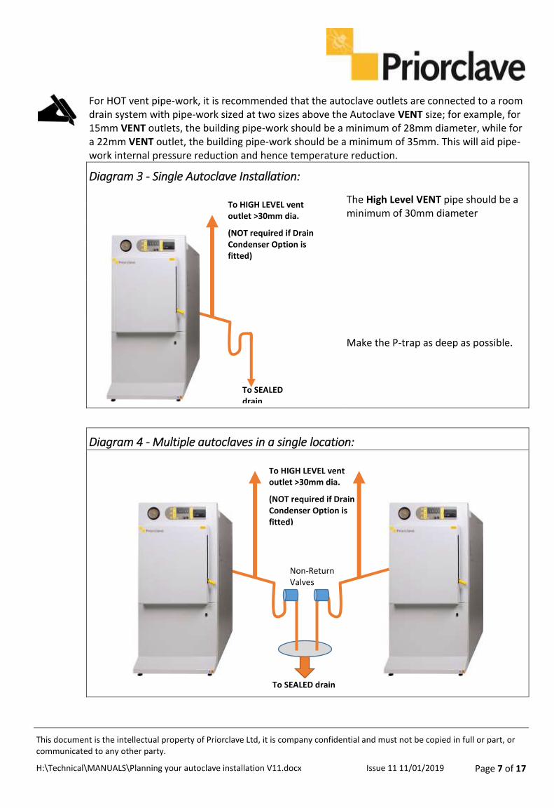
For HOT vent pipe-work, it is recommended that the autoclave outlets are connected to a room drain system with pipe-work sized at two sizes above the Autoclave VENT size; for example, for 15mm VENT outlets, the building pipe-work should be a minimum of 28mm diameter, while for a 22mm VENT outlet, the building pipe-work should be a minimum of 35mm. This will aid pipe-work internal pressure reduction and hence temperature reduction.
Diagram 3 - Single Autoclave Installation:
The High Level VENT pipe should be a minimum of 30mm diameter
Make the P-trap as deep as possible.
Diagram 4 - Multiple autoclaves in a single location:
To HIGH LEVEL vent outlet >30mm dia.
(NOT required if Drain Condenser Option is fitted)
To SEALED drain
To HIGH LEVEL vent outlet >30mm dia.
(NOT required if Drain Condenser Option is fitted)
To SEALED drain
Non-Return Valves
This document is the intellectual property of Priorclave Ltd, it is company confidential and must not be copied in full or part, or communicated to any other party.
H:\Technical\MANUALS\Planning your autoclave installation V11.docx Issue 11 11/01/2019 Page 8 of 17
If more than one autoclave is to be installed at a single location then the services described need to be provided for each autoclave. If more than one autoclave is utilising the same drain and/or vent arrangement, then there may be problems due to cross flow of effluent between autoclaves. For example if one autoclave is being loaded by the operator whilst the other is in the Free-steaming stage, then it may be possible for hot air and steam being discharged by one autoclave to enter the other presenting a hazard to the operator. If common services are to be shared it is essential that these are sufficiently isolated from one another to prevent cross flow.
2.1.2 Cold drain: Connection points C, D and E in Diagram 2)
There may be a small number of water tanks and drip trays fitted within the Autoclave. Any over-flows or water outlets from these components are connected together to provide drain points from the Autoclave.
A separate drain is advised for the connection of water tank and drip tray outlets. This can be connected to any room drain system as the water is generally cold, clean and at low pressure. Any drain pipe material is adequate for this type of outlet.
This may be a common connection to the same drainage system as above, but in such cases a sufficient level of isolation (such as a deep trap) is required to prevent the cross flow of steam between the drains.
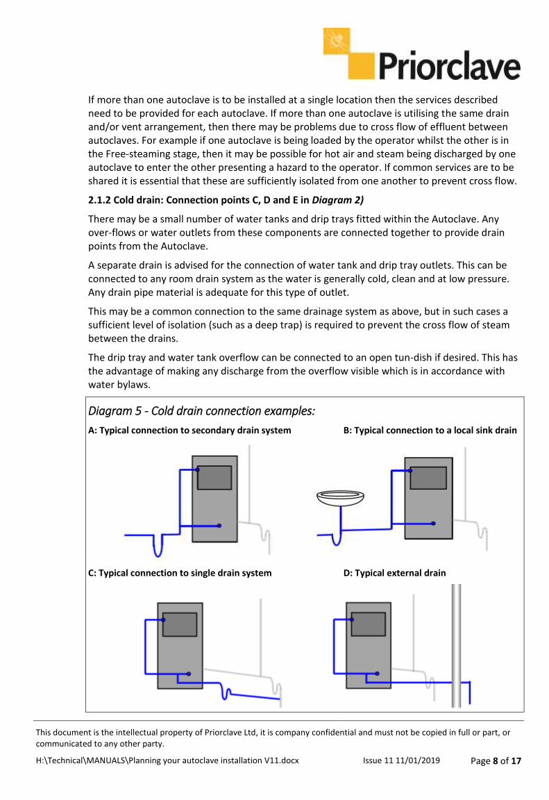
The drip tray and water tank overflow can be connected to an open tun-dish if desired. This has the advantage of making any discharge from the overflow visible which is in accordance with water bylaws.
Diagram 5 - Cold drain connection examples:
A: Typical connection to secondary drain system B: Typical connection to a local sink drain
C: Typical connection to single drain system D: Typical external drain

This document is the intellectual property of Priorclave Ltd, it is company confidential and must not be copied in full or part, or communicated to any other party.
H:\Technical\MANUALS\Planning your autoclave installation V11.docx Issue 11 11/01/2019 Page 9 of 17
Table 1 - Connection Sizes by Model: (Please refer to Diagram 2)
Connection Point Model Connection Required
Safety Valve A Compact 15mm QCS Series 15mm 320L+ QCS (Q63) 22mm RSC Series 22mm
VENT Outlet B Compact (40L) 15mm (60L) 22mm QCS Series 22mm 320L +QCS (Q63) 22mm RSC Series 28mm
Overflow Outlet C Compact
(40L) 15mm (60L) 22mm QCS Series 22mm 320L +QCS (Q63) 22mm RSC Series 28mm
Cold Water Inlet D Compact ½” BSP Male ALL Other Models ¾” BSP Male
Treated Water INLET E All Models 15mm
Vacuum Water Inlet F Compact Not Applicable QCS Series 15mm RSC 22mm
Air Filter G ALL models ½” BSP Female
Direct Steam Inlet H Compact Not Applicable ALL Other Models ½” BSP Male
2.2 Exhaust filtration:
If levels of containment of effluent greater than those described above are required it is possible to fit an exhaust filtration system. In such cases all deliberate discharge from the autoclave vessel is passed through a filter with a validated absolute removal capability to particles sizes of 0.01 microns in gas, and 0.2 microns in liquid.
Depending on specification filter mediums are either of the sintered borosilicate glass or PTFE membrane types. The filter is either mounted inside the autoclave chamber or in a sealed housing outside the autoclave chamber.
Regular filter replacement is essential throughout the life of the autoclave. The details of the requirement, or otherwise, for exhaust filtration are beyond the scope of this document and should be discussed with Priorclave technical personnel. It is not usual to filter discharge from the autoclave safety valve.

This document is the intellectual property of Priorclave Ltd, it is company confidential and must not be copied in full or part, or communicated to any other party.
H:\Technical\MANUALS\Planning your autoclave installation V11.docx Issue 11 11/01/2019 Page 10 of 17
2.3 Air intake filtration: Connection point G Diagram 2
In the case of an autoclave used for the making safe of laboratory waste the drainage provisions described earlier should be adequate.
In the case of autoclaves used for processes in which the product is required to be sterile at the end of the cycle it should be noted that air will return to the chamber via the vent pipework, and will carry with it some airborne contamination. If this is a concern the fitting of an air intake filtration system should be considered. The Priorclave part number for this is PC/INT/000. This device ensures that all air returned to the chamber at the end of the cycle is passed through a filter with an absolute removal capability for particle sizes down to 0.02 micron.
2.4 Safety valve: Connection point A Diagram 2
All pressure vessels within an autoclave are fitted with an over pressure safety valve to protect the autoclave from over pressurisation. This valve will emit large volumes of steam in the event of the autoclave exceeding its maximum working pressure. It is a requirement during safety valve function and routine testing to be able to see and hear if the safety valve has operated.
It is Priorclave’s preferred policy to direct the safety valve outlet to discharge to the floor at the rear of the autoclave in line with recommendations made within the HSE Guidance Note, PM73 – Safety at Autoclaves which states “the Safety Valve outlet should be visible and / or audible and cannot injure any person.”
Under no circumstances should any isolating valve or device be fitted to the drainage point of the Safety Valve, thereby inhibiting its ability to act correctly in the event of a fault.
See also BS3970 part 1 1990, sections 7.2.4 and 7.2.5.
2.5 Steam Supply & Connection - Steam and Dual Steam/Electric models only: Connection point H
Diagram 2
These types of autoclave require a dry saturated steam supply regulated to approximately 3bar/45psig supplied via a 100 mesh strainer. A suitable pressure reducing valve should be provided along with 2 x 100mm pressure gauges showing regulated and unregulated pressure, these should be located within view of the intended site of the autoclave. A condensate trap set should be located in the supply within 1 metre of the connection to the autoclave. If required for the satisfactory operation of the reducing valve a condensate trap set should be located in the supply to the pressure reducing valve. If a steam quality test port is required this should be incorporated into the supply pipework.
The autoclave will be supplied with a flexible steam hose of one metre in length. The steam supply should be terminated with a 1/2” BSP/ DN15 female thread within 1M of the connection to the autoclave to permit connection of the flexible hose. Hoses in two and three metre lengths can be supplied at no additional charge if requested, however the shorter length is recommended for better appearance and reduced condensate accumulation. Longer hose lengths must be specified in writing to your nominated Priorclave project manager prior to delivery of the autoclave. Delivery and repeat visit charges may be incurred if this is not done.

This document is the intellectual property of Priorclave Ltd, it is company confidential and must not be copied in full or part, or communicated to any other party.
H:\Technical\MANUALS\Planning your autoclave installation V11.docx Issue 11 11/01/2019 Page 11 of 17
Diagram 6 - Sample Steam Set:
Example only – please check with your Maintenance Department or Building Management for any additional requirements.
Sep
arat
or
Approx. 300mm
Ap
pro
x. 1
00
0m
m
Flo
at T
rap
Stra
iner
STEA
M IN
Pre
ssu
re
Red
uci
ng
Val
ve
Air
Ven
t
Pre
ssu
re G
auge
(w
ith
sh
ut-
off
) P
ress
ure
Gau
ge
(wit
h s
hu
t-o
ff)
Sigh
t G
lass
/ C
hec
k V
alve
Sto
p-V
alve
Sto
p-V
alve

This document is the intellectual property of Priorclave Ltd, it is company confidential and must not be copied in full or part, or communicated to any other party.
H:\Technical\MANUALS\Planning your autoclave installation V11.docx Issue 11 11/01/2019 Page 12 of 17
A manual isolation valve should be fitted to the steam inlet line (a DN15 isolation valve is supplied with the autoclave).
Diagram 6 shows a typical, but by no means definitive example of a reducing valve and trap set arrangement, which could be used to serve a single autoclave. Priorclave can provide assistance in planning a steam arrangement for a whole suite of autoclaves if required.
In the case of removal of an existing autoclave consideration should be given to which parts of the steam supply are integral to the old autoclave. It is possible that some parts may need to be retained, and re-mounted to suit the new autoclave.
2.6 Electrical supply:
2.6.1 – Compact Models and Non-Vacuum External Steam Models (13A)
When supplied within the UK these will be supplied with a wired standard fused UK plug.
It is important to note that the earth bonding of the plug and cable arrangement is tested before dispatch from the factory, if it is necessary to remove the plug to make alternative arrangements for connection the installation will require re-testing.
2.6.2 – QCS Series models for Single Phase Connection
The electrical supply as per the required specification should be terminated in an industrial socket to BS 4343 (IEC/EN 60309-2), which should be located on the wall to the rear of the autoclave within two metres of the connection to the autoclave. The socket should be of the 1P + N & E type rated at 32 Amps.
If not provided as part of the industrial socket a suitable means of isolation is required to be located in a position where it can easily be accessed to terminate power to the autoclave when necessary.
The socket and isolator should be installed and tested in accordance with current IEEE Wiring Regulations. If existing electrical services from a previous installation are used this should be examined and tested in accordance with the above regulations by a qualified electrician.
If installation is ordered the autoclave is supplied with a plug suitable for connecting to a socket of the above specification. This is connected by a three metre flexible cable to the rear of the autoclave.
It is important to note that the earth bonding of the plug and cable arrangement is tested before dispatch from the factory, if it is necessary to remove the plug to make alternative arrangements for connection the installation will require re-testing.
2.6.3 – All other Models
The electrical supply as per the required specification should be terminated in an industrial socket to BS 4343 (IEC/EN 60309-2), which should be located on the wall to the rear of the autoclave within two metres of the connection to the autoclave. The socket should be of the 3P + N & E type rated at 16, 32 or 63 Amps dependent upon the autoclave specification.
If not provided as part of the industrial socket a suitable means of isolation is required to be located in a position where it can easily be accessed to terminate power to the autoclave when necessary.

This document is the intellectual property of Priorclave Ltd, it is company confidential and must not be copied in full or part, or communicated to any other party.
H:\Technical\MANUALS\Planning your autoclave installation V11.docx Issue 11 11/01/2019 Page 13 of 17
The socket and isolator should be installed and tested in accordance with current IEEE Wiring Regulations. If existing electrical services from a previous installation are used this should be examined and tested in accordance with the above regulations by a qualified electrician.
If installation is ordered the autoclave is supplied with a plug suitable for connecting to a socket of the above specification. This is connected by a three metre flexible cable to the rear of the autoclave.
It is important to note that the earth bonding of the plug and cable arrangement is tested before dispatch from the factory, if it is necessary to remove the plug to make alternative arrangements for connection the installation will require re-testing.
Section 3 - Water supplies and backflow prevention
3.1 Water Supply (Water Fittings) regulations:
Note: The fluid categories below relate only to the above regulations, and are in no way connected with the containment categories previously discussed with reference to drainage and containment of pathogens.
It is mandatory that the completed installation complies with current Water Supply (Water Fittings) regulations. This will be dependent on factors outside of the autoclave such as the layout of the water supply provided. The location and usage of the autoclave will determine the fluid category for which backflow prevention measures are to be taken, however it is suggested in the guidance notes to the above regulations that all laboratories in industrial and commercial installations are considered category 5. Prevention measures suitable for fluids in this category may therefore need to be considered.
The backflow prevention measures already provided within the autoclave are as follows:
3.2 Autoclaves with automatic water fill systems, and liquid ring vacuum pumps
Water is fed to the autoclave vessel and vacuum pump via a header tank with air gap and circular overflow, which is classified type AF. This alone will provide backflow prevention measures suitable for fluids up to category 4. Provided that the supply to the autoclave is delivered via a header tank with similar prevention means elsewhere in the building the installation will form an air gap with interposed cistern of type AUK, which is suitable for fluids up to category 5. Separate header tanks for each of these functions are provided allowing the automatic water fill tank to be fed from a treated water supply, and the vacuum pump to be fed from an untreated supply to economize on the use of treated water if required. Considerations for the use of treated water are discussed later.
3.3 Autoclaves with water cooled condensers
For installations falling into lower fluid categories it will be possible to use mechanical means to prevent back flow such as a verifiable single, or non-verifiable double check valve. For higher fluid categories non mechanical means such as break tanks must be applied. Due to the pressure and flow rates required for the condensers to work effectively it is not practical to provide header tanks locally to the autoclave. The condenser will work more effectively when more cooling water flow is achieved across the condenser, therefore the more head of water that can be provided the better.

This document is the intellectual property of Priorclave Ltd, it is company confidential and must not be copied in full or part, or communicated to any other party.
H:\Technical\MANUALS\Planning your autoclave installation V11.docx Issue 11 11/01/2019 Page 14 of 17
Arrangements to meet the backflow prevention requirements will therefore need to be made at a high level. If a water feed from a suitable header tank arrangement to satisfy the regulations cannot be provided it will be necessary to take other measure such as the provision of a break tank and pump arrangement locally to the autoclave.
3.4 Water Supplies - General
All water supplies should be terminated on the wall to the rear of the autoclave, at a point within one metre of the point of connection to the autoclave.
In hard water areas it will be necessary to use softened water for the supplies to the autoclave to prevent scaling of the autoclave vessel and heating elements.
Hard water can also reduce the life span of liquid ring vacuum pumps and drain condensers when fitted, however the cost of supplying treated water to these may be considered prohibitive, and if this is the case, then a second water supply will be required.
If the autoclave is to be connected to a distilled or de-mineralised water supply care should be taken to guard against the corrosion of copper pipework due to excessive purity of the water supply.
The water level detection system of most autoclaves is operated on a conductivity-based system, due to this feed water requires a minimum conductivity level of 100 micro Seimens.
Water supply pressure should be in the range of 3.0 to 4.0bar.
Water supply flow rate should be 0.5m3/hr
Section 4 Provision of space and access for accessories
4.1 Autoclaves with drain condensers
Drain condensers are fitted internally or to the rear panel of front loading autoclaves, and require sufficient space to be allowed for pipework to enter the condenser. Drain condensers for top loading autoclaves may be supplied as separate units and consideration should be given to where the condenser is to be located as it may not be practical to site this to the rear of the autoclave. Drain condensers may operate at high temperature depending on final settings, and effectiveness of the cooling water supply.
Consideration should be given to heat hazards when deciding on the location of a condenser.
For externally mounted condensers, once all pipework is complete the condenser will occupy a space of approximately 300 x 500mm.
4.2 Autoclaves with exhaust filtration
The location of exhaust filters will vary according to the individual specification of the autoclave. In the case of rectangular vessel autoclave the filter is sometimes fitted inside the autoclave vessel, and in such cases further consideration of the filter location is not necessary.
In the case of top loading and smaller front loading autoclaves it is not possible to locate the filter inside the vessel due to space constraints and limitations of currently available filter mediums. It is then necessary for the filter to be located in a separate pressure vessel outside of the autoclave.

This document is the intellectual property of Priorclave Ltd, it is company confidential and must not be copied in full or part, or communicated to any other party.
H:\Technical\MANUALS\Planning your autoclave installation V11.docx Issue 11 11/01/2019 Page 15 of 17
External exhaust filter housings are located to the upper rear of the autoclave, and protrude from the left-hand side as viewed from the front of the autoclave by up to 200mm. In normal circumstances the filter housing will fit into the 300mm space already provided to the rear of the autoclave. Special arrangements for the location of exhaust filters can be made on request.
It is normal for exhaust filter housing to reach temperatures in excess of 100oC, therefore consideration should be given to heat hazards when deciding on the location of an autoclave with an exhaust filter. Provision should be made to protect personnel from heat hazards whist maintaining adequate access for filter replacement. A minimum height of 500mm is required above the top of the filter housing for replacement of the filter.
Important Notes:
Provision should be made to guard or insulate pipes exiting the autoclave where these may present a heat hazard.
If the services described in this document and from the acknowledgement questionnaire sent at the time of order are not available on the day of commencement of installation it may not be possible to complete the installation as scheduled.
Charges for repeat visits may be incurred if it is necessary to re-install to modified services.
Section 5 Delivery and access
5.1 General considerations
When considering the location for a new autoclave it is obviously necessary to consider how the autoclave will be transported to the point of installation. In the case of replacement of older autoclaves of similar dimensions it may be wrong to assume that as the old unit has been in place for some time a suitable delivery route must exist. It may be that an existing autoclave was delivered via a route which was only available for a limited period whilst construction work was underway, or that subsequent building work has led to a previously existing route becoming unavailable.
Also it is not uncommon for a certain amount of building in place to occur, meaning that old autoclaves may require some dismantling before removal.
Priorclave will be pleased to arrange for site surveys to be conducted by ourselves, or specialist subcontractors. We are able to assist in the planning of delivery and siting, and removal of redundant autoclaves. In some circumstances we may charge for site surveys.
For all deliveries suitable protection should be provided to prevent damage to floor coverings and interior decoration and fittings. Unless specified this will not be provided as part of the delivery.
Before attempting to move a newly delivered autoclave within a building on the built-in castors it is essential to check these for damage or entrained debris as this is likely to cause damage to floor coverings. The castors fitted to the autoclaves are intended for moving the autoclaves over interior floor surfaces, and damage is likely to occur if attempts are made to move autoclaves over rougher exterior surfaces such as concrete and paved areas. In some cases it

This document is the intellectual property of Priorclave Ltd, it is company confidential and must not be copied in full or part, or communicated to any other party.
H:\Technical\MANUALS\Planning your autoclave installation V11.docx Issue 11 11/01/2019 Page 16 of 17
may be preferable to use skates, or a suitable trolley to move the autoclave, or to put down protective sheeting.
5.2 Measuring for access
When measuring access routes to plan delivery of your autoclave, critical points such as turning tight corners, should be assessed using a two dimensional template of the autoclave. A tape measure will not provide adequate detail. 1:1 scale paper templates of each of our autoclaves are available for this purpose. In case of any doubt always err on the side of caution, any out of true errors in walls or floor will make will make access tighter than it will appear with the use of a two dimensional template. Most autoclaves are usually delivered with small items such as door handles, pipes and electrical isolators protruding from the rectangular dimensions quoted as external size. Arrangements can be made to have these removed for delivery.
5.3 Standard delivery
Our standard delivery method is by enclosed air sprung van with a large tail-lift. The delivery will be made by a minimum two-man crew, and delivery includes siting the autoclave at the point of installation. This assumes clear vehicle access to a level unloading site, or loading bay, and a flat route (including via elevator) to the point of installation. Vehicles are equipped with a limited amount of ramp building and staging equipment and stair-walking equipment is available for most sizes of autoclave.
It should be noted however that equipment will need to be allocated by special arrangement, and advanced notification will be required of any access difficulties. The delivery and positioning of smaller autoclaves up to around 200 litres in capacity is usually very simple, and will not require specialised planning or equipment.
It is however important for the purchaser to carefully plan the route from the point of delivery to the point of installation. It will be necessary to ensure that corridors, door frames and lifts etc. are suitable to allow access.
5.4 Specialist delivery
By special arrangement delivery can be made by a vehicle equipped with a vehicle mounted telescopic crane, and other more specialized lifting and moving equipment can be provided. This is usually only necessary for larger, heavier autoclaves, or situations where access is difficult. This will require advanced notification and a site survey, and will incur charges in excess of standard delivery rates. A job specific method statement will be provided for each such delivery.
Priorclave cannot accept responsibility for costs of building work or other modifications required in order to site autoclaves unless specifically agreed in writing. In the absence of a site survey conducted by ourselves or subcontractors we can accept no liability for costs incurred as a result of delivery being prevented by access difficulties. Whilst we will endeavour to take every care in assisting in the planning of the delivery and siting of the autoclave we cannot accept responsibility for costs incurred as a result of unforeseen circumstances.
5.5 Two stage removal and delivery
Often, particularly in the case of refurbishment, it is desirable for the redundant autoclave to be removed some time prior to the delivery of new equipment. This allows access for

This document is the intellectual property of Priorclave Ltd, it is company confidential and must not be copied in full or part, or communicated to any other party.
H:\Technical\MANUALS\Planning your autoclave installation V11.docx Issue 11 11/01/2019 Page 17 of 17
refurbishment work to be conducted, and modifications to services etc. to be performed. Priorclave will be pleased to arrange this for a modest additional charge. For a “rule of thumb” guide this will be approximately double the delivery charge for the new autoclave, assuming no dismantling is required.
All redundant autoclaves are disposed of in an environmentally acceptable manner, and as much material as possible is re-cycled.
5.6 Safety
All deliveries will be made by personnel trained in the use of all equipment required for completion of the delivery and positioning of the equipment. All personnel are equipped with high visibility clothing, and protective footwear and safety helmets. If any further safety equipment is required for a particular delivery advanced notification will be required. If delivery personnel are required to undergo a site safety induction advanced notification will be of benefit.
It is envisaged that sufficient manpower and equipment will be provided for delivery such that it will not be necessary for the purchaser’s staff, or contractors to become involved in the moving of the autoclave. However in circumstances where additional assistance is required it will be necessary for the appropriate protective equipment to be worn by anyone providing assistance, and for care to be taken to prevent personal injury. Priorclave can accept no responsibility for damage or injury sustained during manoeuvring of autoclaves.
The information and recommendations documented in “Planning your Autoclave Installation” are given in good faith and to be of assistance to the purchaser, and its contractors However Priorclave Ltd., Prior Group Holdings Ltd. and the members or staff of these companies accept no liability in respect of any loss or claim arising from errors and omissions in the information provided.
Any suggestions for inclusion or modification are welcome. This document is regularly updated and it is advisable to obtain updated copies prior to each installation.
© Copyright Priorclave 2019
Priorclave Ltd.
129-131 Nathan Way T. +44 (0)208 316 6620 [email protected] London SE28 0AB. F. +44 (0)208 855 0616 www.priorclave.co.uk