plans for experiment protection at lhc
DESCRIPTION
PLANS FOR EXPERIMENT PROTECTION AT LHC. Introduction: Lessons from the past The L arge H adron C ollider LHC protection strategy Beam interlock system Failure scenarios Risks for the Expts LHC Experiment protection Beam conditions monitors, etc. Detectors damage threshold - PowerPoint PPT PresentationTRANSCRIPT

Tw
epp2
009
M
assi
mili
ano
Fer
ro-L
uzzi
1
PLANS FOR EXPERIMENT PROTECTION AT LHC
Introduction:– Lessons from the past– The Large Hadron Collider
LHC protection strategy– Beam interlock system
Failure scenarios– Risks for the Expts
LHC Experiment protection– Beam conditions monitors, etc.
Detectors damage threshold– What do we know for silicon ?
Conclusion and outlook
Note: I won't address heavy ion beams
Special thanks to: Antonello di Mauro, Siegfried Wenig,
Richard Hall-Wilton, Richard Jacobsson, Jorg Wenninger, Rudiger Schmidt, Rob Appleby, Daniela Macina, etc.

Tw
epp2
009
M
assi
mili
ano
Fer
ro-L
uzzi
2
It happens ...
SppS: – 198x: electrostatic separators adjusted for 315 GeV, instead of injection energy of 26 GeV
=> UA2 gets beam injected repeatedly into detector, no fast feedback from the Expt LEP:
– 1991: Quad polarity switched... consecutive splashes into L3, damage to BGO lumimonitor (later, in 1992, further failures with damage to endcap calorimeter...)
– 1993: Quad failure ... Aleph loses fraction of VDET due to shorting of AC capacitor chips RHIC:
– 2000: Phobos: several missed aborts, lose 1-2% of their Si pad detector channels
(other RHIC experiments affected as well). HERA:
– 2002: damage caused to H1 Si pad and strip detectors (BST) and their electronics. Tevatron:
– 2002: asynchronous dump, CDF loses six ladders of vertex detector due to chip failure
Lessons: it does happen! better have a protection system in the experiment to trigger beam abort better have some sort of monitor during injection (fast feed back to machine!)
See J. Spalding in TeV4LHC April 2005

Tw
epp2
009
M
assi
mili
ano
Fer
ro-L
uzzi
3
Stored Energy of the LHC
360 MJ
A factor 2 in magnetic field A factor 7 in beam energy A factor 200 in stored energy!
A factor 2 in magnetic field A factor 7 in beam energy A factor 200 in stored energy!
4x72x1.1 1011p
2808x1.1 1011p
LHC 2009-2010target

Tw
epp2
009
M
assi
mili
ano
Fer
ro-L
uzzi
4
LHC colleagues performed a controlled experiment with 450 GeV beam shot into a stack target to benchmark simulations.
Copper:– melting point reached at
2.4x10¹² p
– clear damage at 4.8x10¹² p Good agreement with simulation
1.2 2.4 7.2 4.8 x10¹² protons
Definition for the LHC of a “safe” beam limit (setup beam, see later):
1012 protons at 450 GeV
1010 protons at 7 TeV (scaled from 450 GeV)
Note: tests as described above do not correspond to the most typical impact of beam, there is a safety margin on the 450 GeV “safe beam” for typical accelerator equipment.But what about experiments/detectors ?
Damage Potential of LHC Beams
about 3% of a full SPS batch
See V. Kain et al., Material damage test with 450 GeV LHC-type beam, Proc. of 2005 Part. Acc. Conf., Knoxville, Tennessee, and PhD Thesis by V. Kain, CERN-Thesis-2005-047

Tw
epp2
009
M
assi
mili
ano
Fer
ro-L
uzzi
5
The LHC and the Experiments
CMS/Totem:– near dump– roman pots
BEAMDUMP
BEAM CLEANING
BEAM CLEANING
RF
8.5 km8.5 km
LHCb and Alice:– just near injection point– experimental dipole
magnets + correctors– no TAS absorbers– LHCb VELO, similar to
"roman pots"
ATLAS/LHCf:– a cool place to be...

Tw
epp2
009
M
assi
mili
ano
Fer
ro-L
uzzi
6
Typical Insertion Region ( Region Around Experiment )
Here is CMS (same for ATLAS), symmetric at IP:
Here is LHCb (similar for ALICE): injection from SPS !
TAS = absorber to protect triplet from IP primaries NB: Q1-3 contain also some corrector dipoles
• No TAS• presence of dipole magnet + correctors MBXW...
cryomagnet
warm magnet
absorber/
collimator

Tw
epp2
009
M
assi
mili
ano
Fer
ro-L
uzzi
7
LHC Machine Protection
Beam modes:Beam modes: Outside these two beam modes,
movable detectors must be OUT In this state, they should move
OUT (but don't dump if not...)

Tw
epp2
009
M
assi
mili
ano
Fer
ro-L
uzzi
8
LHC “Passive„ Machine Protection : Collimators / Absorbers
Almost entirely cryogenic ring – more than 20 km of superconducting
magnets Quench limits impose collimation!
Lost protons must be intercepted with high efficiency before quench
instantaneous loss in a magnet (~10 m) required < 1010 p at 450 GeV, 106-7 at 7 TeV
– Unlike HERA, TEVATRON, RHIC... the LHC cannot be operated without collimators (except at injection with low intensity).
– At the LHC the collimators must define the aperture (primary + secondary) which has an important impact for Machine Protection: for most multi-turn failures the beam will hit collimators first !
Monitoring:– BLM’s on collimators, on magnets– BPM’s, etc.– Try avoiding quenches by setting dump
thresholds lower than quench values
EnergyGeV
Loss rate (10 h lifetime, 3x10¹⁴ p)
Quench limit (slow losses)
4508.3x109 p s-1
7x10⁸ p s-1 m-1
7000 8x10⁶ p s-1 m-1

Tw
epp2
009
M
assi
mili
ano
Fer
ro-L
uzzi
9
LHC “Active„ Machine Protection : Beam Interlocks
Beam Interlock System– Two redundant BeamPermit loops per
beam around the ring
– Beam Interlock Controller: Makes AND of several UserPermit signals More than 3000 LHC user devices of the BICs
(BLM's, BPM's, etc.) If UserPermit signal is false, then BeamPermit is
false => dump and block injection
BeamPresence– one flag per LHC ring
– at least 5 uA in the ring (fast AC BCT) ProbeBeam
– True if SPS intensity < limit limit = C x 1011 protons (C≤1)
– if BeamPresence and ProbeBeam are false, then cannot inject into LHC
SetUpBeam– based on LHC current, energy dependent:
True if < 1012 (5x10¹⁰) protons at 0.45 (7) TeV. If True, it allows masking some BIS inputs
General strategy:– inject probe bunch (5x10⁹ p)– if OK (circulating), inject higher intensity batch– on dump trigger => extract beam in < 0.3 ms
(1 turn 0.09 ms) Abort gap:
– continuously monitored, at least 3 us long
see LHC Design Report vol. 1
Main Ring

Tw
epp2
009
M
assi
mili
ano
Fer
ro-L
uzzi
10
Impossible Failure Scenarios ...
For the experiments, these are the worries:For the experiments, these are the worries:
Injection failures:– incomplete or unsynchronized kicker fire => mostly Alice & LHCb– wrong magnet settings in transfer line => mostly Alice & LHCb– wrong magnet settings in the LHC => everybody
Circulating beam failures: mostly caught by collimators– magnet failure / mishap => everybody– RF failure => everybody– collimator failure / mishap => everybody
Extraction failures:– underkick, unsynchronized beam dump => mostly CMS
Expect Expts to be protected by "early" cryomagnet quench protection
We'll see some specific examples later

Tw
epp2
009
M
assi
mili
ano
Fer
ro-L
uzzi
11
What kind of particle rates ?
In terms of estimating particle rates to a detector, the only simple (though quite unlikely) LHC failure scenario is– Suppose a batch is injected with wrong magnet settings near an
experiment (remember: a probe beam has < 1011 protons)
– The batch is shot straight into the detector without traversing much material (little showering, less than x10 multiplication), beam size ~ 0.3 mm
– Potentially, of order ~1013 p/cm2 (in <1ns) depending on the maximum value for the ProbeBeam and on the local shower multiplication
– Very high flux density, but very local (could be quite catastrophic if readout chips happen to be on the trajectory)
Other possible failures (with grazing, showering,...) require detailed MC simulations– Work in progress
– A few examples in the next slides

Tw
epp2
009
M
assi
mili
ano
Fer
ro-L
uzzi
12
Example 1: TAS Absorber Grazing Case in ATLAS
Studied wrong settings of MCBX, D1 and D2: due to presence of TAS absorber, pilot beam can never hit directly the Inner Detector.
Thus, most dangerous case is when wrong magnet setting is such that beam scrapes first TAS and hits second TAS.
If a 5x10⁹ bunch is lost in ATLAS due to a single wrongly set magnet, the estimated radiation dose delivered to the b-layer is estimated to be
< 5x10⁻³ Gy or
( Note: in terms of rate this is about 107
more than during a nominal bunch crossing, i.e. ~ 106 MIP/cm2)
ATLAS beam failures simulation:ATLAS beam failures simulation:See Dariusz Bocian, LHC Project Note 335
Specially searched forSpecially searched for two-magnet failures could deposit much more, but such failures are considered much less likely
Injection energy D1 magnet (wrong) setting (should be
about 6.4%)
Injection energy D1 magnet (wrong) setting (should be
about 6.4%)

Tw
epp2
009
M
assi
mili
ano
Fer
ro-L
uzzi
13
Example 2: Extraction Failure and Effect on IP5
Simulations for effect on CMS / IP5 due to unsynchronized abort and kicker prefire, see Drozhdin, Mokhov, Huhtinen, 1999 Particle Acc. Conference
– kicker prefire: one kicker module fires alone; should not happen (system designed such that a firing module fires the other modules)
– unsynchronized abort: quite likely to happen; kicker rise time ~3us => ~120 bunches swept
BEAMDUMP
BEAM CLEANING
Results (for Pixel detector): – Integrated doses not so dangerous, – but rates are!– Up to 108 times higher instantaneous
rates than during nominal running up to 108 x 106 MIP cm-2 s-1 !!
These results led to addition of movable and fixed collimators at IP6 (TCDQ, TCDS) to intercept the bulk of the mis-kicked beam

Tw
epp2
009
M
assi
mili
ano
Fer
ro-L
uzzi
14
Example 3: ALICE Beam Failures Simulation Studies
Effect of kicker failures during injectionEffect of kicker failures during injection See B. Pastirčák et al., Radiation from Misinjected Beam to LHC, ALICE Internal Note 2001-03
Failure scenarios: Failure scenarios: grazing: full batch (4.1x10¹³ p) missing the TDI beam stopper, worst case but very unlikely sweep: prefire of kicker modules, ≈ 20 bunches escape TDI, expected several times/year (?)
main contribution
Results:Results: Accumulated dose during 10 years due to "expected" misinjections is (for Si Pixel Detector and
electronics) about 1 krad (1% of total dose from primary collisions) Energy deposition maps per accident in Alice detector (vertical section):
"grazing" "sweep"
rad rad
cm cm
cm cm
Here, for Si, inner tracker: 100 rad ~ 109-10 MIP/cm2

Tw
epp2
009
M
assi
mili
ano
Fer
ro-L
uzzi
15
Example 4: Wrong Compensator Setting at Injection ( here beam2 IP8 )
Beam2, 450 GeV Wrong setting of MBXWH
(horizontal compensator) Beam can hit LHCb detector
1.0 to 0.55 of max B
Nominal 0.06 LHC Project Report 1174 “LHCb Injected Beam Accidents” R.B. Appleby LHC Project Report 1175 “ALICE Injected Beam Accidents” R.B. Appleby

Tw
epp2
009
M
assi
mili
ano
Fer
ro-L
uzzi
16
Example 5: wrong compensator or corrector settings at injection ( here beam1 IP8 )
Injected beam does not need to come from nearby injection line! Here beam 1 in LHCb (after almost one turn) Valid for all experiments at LHC
Beam1 450 GeVWrong MBXWH1.0 to 0.35 of max BNominal 0.06
Beam1 450 GeVWrong MCBXV1.0 to 0.3 of max BNominal 0.05
LHC Project Report 1174 “LHCb Injected Beam Accidents” R.B. Appleby LHC Project Report 1175 “ALICE Injected Beam Accidents” R.B. Appleby
Tw
epp2
009
M
assi
mili
ano
Fer
ro-L
uzzi
17
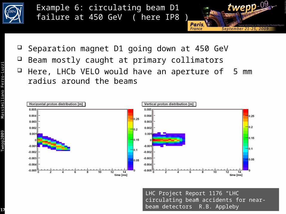
Example 6: circulating beam D1 failure at 450 GeV ( here IP8 )
Separation magnet D1 going down at 450 GeV Beam mostly caught at primary collimators Here, LHCb VELO would have an aperture of 5 mm radius around
the beams
LHC Project Report 1176 “LHC circulating beam accidents for near-beam detectors” R.B. Appleby

Tw
epp2
009
M
assi
mili
ano
Fer
ro-L
uzzi
18
Example 7: Wrong Local Bump
s/w interlocks will be in place
7 TeV/beamWrong (extreme) settings
in 2 MCBX correctors acting coherently
VELO aperture
Normal case
Take again IP8 / LHCbTake again IP8 / LHCb Beams separated in Y (vertical)
during filling, ramping, etc. – Typ. ~ 1 mm between beams
at 7 TeV before colliding
– Max. accessible separation at
7 TeV is a few mm Bump can be local, transparent
to rest of machine! – Example here at 7 TeV with two magnets
The lower the energy, the “easier” to make such a bump– At 450 GeV => accessible separation range amplified by factor 15.5, i.e.
up to few mm x15.5 !!

Tw
epp2
009
M
assi
mili
ano
Fer
ro-L
uzzi
19
LHC Experiment Interlocks
Beam_permit:Beam_permit: In each experiment, several systems
(typically 3 or 4) in “and” mode must be alive and deliver a User_permit
If one system remove the User_permit, it triggers a beam dump
Both beams are dumped Recovery procedure after post-mortem
data analysis
Injection_permitInjection_permit: Separate interlock based on same transmission hardware (signals to SPS extraction) Allows inhibiting injection into LHC, e.g. when
– Detector not ready for injection– Bad injection detected during a fill, requires stopping injection without dumping the stored beam
(emergency buttons are also implemented in some experiments…)
BCM+others
Romanpots
Magnet

Tw
epp2
009
M
assi
mili
ano
Fer
ro-L
uzzi
20
Typical LHC Experiment Protection System
One set of diamond sensors on each side of IP:– Stand-alone system using a few polycrystalline CVD diamond pads
– UPS powered, with few minutes autonomy
– Post-Mortem analysis capability
– FPGA-based dump logic: input: measured rates output: UserPermit signal
– Unmaskable input to local BIC
– On trigger, dump both beams
– Expected ready from "day 1"
– Must have high availability, reliability, efficiency
BCM (beam conditions monitor) must protect detectors against circulating beam failures
about 2 m
a few cm
CVD, 1 cm2
0.3-0.5 mm thick
IP
1 MIP ~ 1 fC

Tw
epp2
009
M
assi
mili
ano
Fer
ro-L
uzzi
21
ATLAS (1)
Beam Loss Monitors (BLMXD.01L1/R1.CH0N_ATLAS)– 2 x 6 pCVD diamond detectors (8 x 8 mm2)– z = ± 345 cm and r = 65 mm– 40 s integration time, pA to mA– Readout chain of LHC BLM system with modified BLMTC FPGA firmware
Abort signal at front panel Receive PM signal
Beam abort condition– 2 in a group of 3 detectors above threshold
BLM
SIDE C
Noise Collisions Thres. Damage~10 pA ~15 nA 50 nA (?) > 1 uA??
At nominal 1e34 cm-2 s-1

Tw
epp2
009
M
assi
mili
ano
Fer
ro-L
uzzi
22
See M. Mikuz et al., NIMA 579 (2007) 788-794
ATLAS (2)
Beam Conditions Monitors (BCM)– 2 x 4 pCVD diamond detectors (8 x 8 mm2)– z = ± 184 cm and r = 55 mm– Fast readout time– Single MIP sensitivity with sub-ns time resolution Time of flight measurement
distinguish collisions – background (ΔT(A/C) = 2d/c)
Beam abort condition (not used at start-up)– 3 sensors above high threshold ( 5 MIPS) AND – 4 sensors above low threshold (0.5 MIPS)
BCM
Pixel Detector
Beam Pipe
d
CAd/c = 184 cm/c = 12.2 ns = ~ 25ns / 2Monitor beam halo by out of time signals vs collisions

Tw
epp2
009
M
assi
mili
ano
Fer
ro-L
uzzi
23
CMS (1)
BCM1L• Leakage current monitor• Polycrystalline Diamond• Usage: Experiment protectionBCM1F• Bunch by bunch monitor• Single crystal Diamond• Usage: Pixel protection
BCM2• Leakage current monitor• Polycrystalline Diamond• Location: z=± 14.4m, r=29cm, 4.5cm• 8 stations in ϕ, 24 sensors total
see L. Fernandez-Hernando et al., NIMA 552 (2005) 183-188

Tw
epp2
009
M
assi
mili
ano
Fer
ro-L
uzzi
24
CMS (2)
Initially only 8 diamonds (4 per end) in inner ring on BCM2 will be “active” in asserting BEAM_PERMIT
BCM1L hardware will be connected to the ABORT from the beginning, however thresholds will NOT be set until after a suitable commissioning period with beam
BCM1L detectors and inner ring of BCM2 are at ca. 4.5cm radius, approximately the same as innermost layer of pixel detector
Initial threshold for BCM2: RS1 ~ 10 uA (40 us)
Thresholds are per diamond. No coincidence required.– Has been running stably for > 6 months, w/o spurious triggers
Noise Collisions Thres. Damage<10 pA ~15 nA 10 uA > 18 uA
At nominal 1e34 cm-2 s-1

Tw
epp2
009
M
assi
mili
ano
Fer
ro-L
uzzi
25
ALICE (1)
L
R
BCM CBCM Cz = -19 mz = -19 m8 diamond sensors8 diamond sensors
BCM A2BCM A2z = +13.5 mz = +13.5 m4 diamond sensors4 diamond sensors
BCM A1BCM A1z = +4.5 mz = +4.5 m4 diamond sensors4 diamond sensors
BLMsBLMs
VO-A VO-A scintillatorsscintillators
VO-C VO-C scintillatorsscintillators
RADMONRADMON

Tw
epp2
009
M
assi
mili
ano
Fer
ro-L
uzzi
26
ALICE (2)
RS2 [nA] RS32 [nA]
BCM A 500-750 30-50
BCM C 100 6
TDI sweep (pilot bunch 5 × 10⁹ p)
RS2 [nA] RS32 [nA]
BCM A 900-2700 55-170
BCM C 325 20
TDI grazing (pilot bunch 5 × 10⁹ p)
Injection test Aug 9-11 2008Beam through ALICE
BCM currents from FLUKA simulation of injection failures by B. Pastirčák (ALICE Int. Note 2001-03), updated in Nov 07
I [n
A]
time
The UserPermit is based on BCM-CFC-TELL1 chain as in LHCb.– Fast abort on RS2 (2x40s CFC integration frames) coincidences:
Dump beam if 3 of 4 adjacent diamond sensors show current > thrRS2 – Slow abort on RS32 (32x40s):
Sorting out the two highest and the lowest of 8 sensors, dump beam if RS32 > thrRS32
Current estimate for dump thresholds (to be x-checked …):– thrRS2 ~ 5000 nA , thrRS32 ~ 250 nA
Noise Collisions Thres. Damage<100 pA ~100 pA ~ 5 uA ~ mA

Tw
epp2
009
M
assi
mili
ano
Fer
ro-L
uzzi
27
LHCb (1)
Each BCM station composed of 4 or 8 CVD diamonds Mounted on the beam pipe, about 6 cm away from beam axis Asymmetric layout of BCM around IP (space availability) Diamonds readout: integrated rates in 40 us (later upgrade to 25 ns ?) Use stand-alone readout board for algorithm on dump trigger decision Simulations ongoing (relate VELO rates to BCM rates in failure
scenarios)
BCMBCM
VELOVELO
beam pipe supportbeam pipe support
diamondsdiamonds
Noise Collisions Thres. Damage<10 pA ~1 nA few uA > ?? uA

Tw
epp2
009
M
assi
mili
ano
Fer
ro-L
uzzi
28
LHCb's Special: Vertex Locator
+/-5 mm
30 mm
Beam
30 mm
Injection: no material at r<27 mm Velo open (OUT) During stable beam Velo closed (IN) Final position adjustable in y and in x to center beam
in the hole (axial geometry for RZ trigger !) It must be possible to adjust "beyond" nominal beam
axis (beam position not guaranteed...) Microswitches to detect Velo is OUT (both halves) Microswitches and hard stops to prevent crashes
5 mm radius5 mm radius
0.25 mm Al foil0.25 mm Al foil
21 r-phi Si modules per side21 r-phi Si modules per side
0.25 um CMOS ASICs (Beetle)0.25 um CMOS ASICs (Beetle)

Tw
epp2
009
M
assi
mili
ano
Fer
ro-L
uzzi
29
LHCb VELO Protection System
Microswitches in X on each half to check that VELO is in garage position (OUT)
Read out by PLC which generates Device_out signal
LHC flag Device_allowed transmitted via reliable network to the Expts. If False, movable devices must be in OUT position
If both LHC flag Device_allowed and VELO flag Device_out are false, then LHCb UserPermit is false => dump the beam, prevent injection
VELO motion is "slow", of order 0.1 mm/s
Can move over nominal beam axis and/or beam can move to the detector!
fast protection needed !
BCM must detect increase in rate (over normal minimum bias events) due to a possible beam-velo foil scraping,
must work for both beams
"IN" 5 mm"OUT" 30 mm
beam
BCM
VELOpos
Magnet
AND
Device_out = true Device_out = false
actual beamnominal beam axis

Tw
epp2
009
M
assi
mili
ano
Fer
ro-L
uzzi
30
Damage thresholds for detectors
What are the most exposed / most sensitive detectors ?
What are their damage thresholds ?
Why do we care ?
Detectors are designed, built and installed: but operation procedures can be changed– HV and LV on/off at injection or with “non-physics” circulating beam ?
Feedback to the machine– Definition of intensity limit at injection
Currently H/W 1011 protons and S/W 1010
Improvements on future detectors (at even higher beam intensities...)

Tw
epp2
009
M
assi
mili
ano
Fer
ro-L
uzzi
31
Risks for LHC Vertex Detectors
Problems with beam losses for the silicon:Problems with beam losses for the silicon: Heat deposit: not a problem ? (for the likely failures)
– Thermomechanicql effects ? Seeds for crqcks ? Extra radiation damage, eating up the "budget"
– not so critical: LHC Si detectors designed to sustain "huge" doses (few 1014 neq/cm2 ~ 10 Mrad) ;
– but watch out anyway! Sudden high rate can induce large voltage in the Si detector
– becomes essentially conductor => bias voltage boundary moves to another place... zap or no zap ?
e.g. SiO2 breaks at ~ 1V/nm
– direct hit to FE chip can be even worse (lose full chip, i.e. many channels... see CDF accidents)
The The keep-it-always-on-or-notkeep-it-always-on-or-not dilemma: dilemma: Keep detector always ON for stability ?
– no charge up effects, no temperature effects, etc. Reduce risk during injection by turning OFF HV ? (or
even LV off)? – unstable at turn-ON
Ubias Ubias
Si
insulator
What do we know about What do we know about LHC Expt Si detector and LHC Expt Si detector and resistance to high rates ?resistance to high rates ?
For comparison:• Atlas/CMS pixel (r=4.3cm): order of
0.02 MIP/cm2 per pp interaction• LHCb VELO: order of 0.5 MIP/cm2
per pp interaction• MIPs through pixel detectors due to
pp collisions in IP1/5 in a nominal year ~ 1017...18
• One nominal LHC bunch: 1011 p• Full nominal LHC beam: 3 x 10¹⁴ p

Tw
epp2
009
M
assi
mili
ano
Fer
ro-L
uzzi
32
High Particle Rate Tests On LHC Silicon Detectors
ATLAS and CMS tests at CERN PS beam: ATLAS and CMS tests at CERN PS beam: 24 GeV, 1 or few-bunch batch (bunch: 42 ns long, ~1011 p, separation 256 ns),
with peak bunch density of ~ 3x10¹⁰ p/cm2. Detectors biased and FE electronics ON
ATLAS: – See A. Andreazza, K. Einsweiler, C. Gemme,, L. Rossi, P. Sicho, NIM A 565 (2006) 50–54, Effect of
accidental beam losses on the ATLAS pixel detector
CMS:– See M. Fahrer, G. Dirkes, F. Hartmann, S. Heier, A. Macpherson, Th. Müller, Th. Weiler, NIM A518
(2004) 328–330, Beam-loss-induced electrical stress test on CMS Silicon Strip Modules
Laser tests (not exhaustive):Laser tests (not exhaustive): Atlas silicon strip: 1064 nm LASER (1 W)
– K. Hara,T. Kuwano, G. Moorhead, Y. Ikegami, T. Kohriki, S. Terada, Y. Unno, NIM A 541 (2005) 15–20, Beam splash effects on ATLAS silicon microstrip detectors evaluated using 1-w Nd:YAG laser
Atlas silicon strip sensors: LASER (2 types)– T. Dubbs, M. Harms, H. E-W. Sadrozinski, A. Seiden, M. Wilson, IEEE Trans. Nucl. Sci. NS47 (2000)
1902, Voltages on Silicon Microstrip Detectors in High Radiation Fields

Tw
epp2
009
M
assi
mili
ano
Fer
ro-L
uzzi
33
ATLAS High Particle Rate Test
Andreazza et al., NIM A 565 (2006) 50–54
« The results of the PS experiment therefore indicate that the loss of a LHC ‘‘pilot beam’’ of 5x10⁹ protons should not make any sizeable permanent damage to the performance of the ATLAS pixel detector. This accident will, very likely, require a reloading of the configuration parameters in a large fraction of the pixel detector. »
Tw
epp2
009
M
assi
mili
ano
Fer
ro-L
uzzi
34
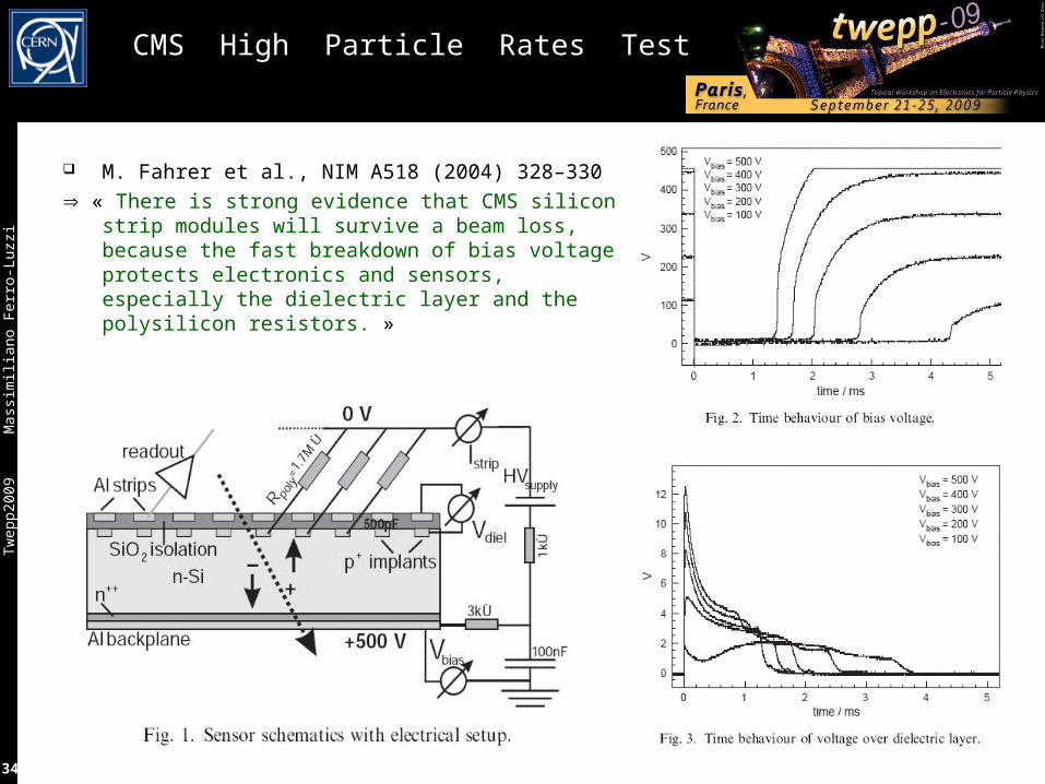
CMS High Particle Rates Test
M. Fahrer et al., NIM A518 (2004) 328–330
« There is strong evidence that CMS silicon strip modules will survive a beam loss, because the fast breakdown of bias voltage protects electronics and sensors, especially the dielectric layer and the polysilicon resistors. »

Tw
epp2
009
M
assi
mili
ano
Fer
ro-L
uzzi
35
A Recent LHCb VELO High Rate Test
VELO/LHCb "High Rate Test„VELO/LHCb "High Rate Test„It‘s hereIt‘s here
RestoResto22Main Main bldgbldg

Tw
epp2
009
M
assi
mili
ano
Fer
ro-L
uzzi
36
A Small Scale Experiment
Module mounted close to the PS booster (PSB) beam dump Proton beam of 1.4 GeV kinetic energy Intensity from 2e9 to 9e12 p/bunch 1 to 4 bunches (4 rings), we use a single bunch (ring 3) Beam spot size rms ~ 2-4 mm , bunch duration rms ~ 20-60 ns
Velo module

Tw
epp2
009
M
assi
mili
ano
Fer
ro-L
uzzi
37
The Victim: “Module 48”
LHCb/Velo spare from production•Back-to-back R & Phi sensors •2048 AC coupled n-on-n strips / side•16 FE chips (IBM 0.25 µm) per side, all configured but only 8 per side read out
Mounted in the beam line•Cooled to +1 ˚C (LV on) with vortex tube (8 bar compressed air)•Fluorescent screen to view the beam•Insert/retract from beam line•Remote control and read-out•Heavy radiation environment !
Backsplash at every beam dump ~ 1 kGy in a few months

Tw
epp2
009
M
assi
mili
ano
Fer
ro-L
uzzi
38
10 MΩ
GND probe
HV probe
Osc. GND
22 nF
1 kΩ
10 MΩ
10 pF
10 pF
Electrical model – static case
Al
SiO2
n
p+
n+
CDETRDET
CACRbias
CRC
QRCCRC
RRCRRC
HV bias (-300V)
HV return (GND)
QRC
RC filter
GND bonds (16x5)
pre-amp
CFB
Vfp
CG
protection diodes
bond wires
FE inputs (2048 channels)
VDD bonds (16x4)
LV (GND)
LV (VDD)
CLV
CDET = 1 nF/2048 ch. RDET = 1-100 MΩ/2048 ch.CAC = 250 nF/2048 ch.Rbias = 1 kΩ x 2048 ch.CRC = 10 nFRRC = 5 kΩCFB = 400 fF (per ch.)CG = 10 pF (per ch.)CLV = 32 x 100nF

Tw
epp2
009
M
assi
mili
ano
Fer
ro-L
uzzi
39
B11
B15 B14
B9
B8
B10
B13
B12
The measurement sequence - observables
Intensity steps: 2x10⁹, 2x10¹⁰, 2x10¹¹, 2x10¹² & 9x10¹² Each step: LV/HV off, LV on/HV off, LV on/HV 150 V & LV on/HV 300V Each beam ‘shot’ follows the same pattern
– A set of standard measurements I/V of both sensors Noise & pedestal data Test pulse data at +1.5, 0 and -150 V
– Insert the module, acquire during the shot 14 consecutive triggers of front-end data Voltage on hybrid GND and sensor bias via
oscilloscope Beam spot image via a a camera
– Repeat the same set of measurements Shots on two sensor positions Shots on five front-end chips
(here only LV on/off matters)

Tw
epp2
009
M
assi
mili
ano
Fer
ro-L
uzzi
40
Beam images
Beam line camera on fluorescent screen
Combined R-Φ sensor front-end data

Tw
epp2
009
M
assi
mili
ano
Fer
ro-L
uzzi
41
I/V curves
I/V curves in-situ between each shot– Superimpose temperature corrected I/V curves– Small increase probably due to accumulated dose– Rough estimate between first and last curve: ~3.5x10¹² 1-MeV-neq /cm2 (~1 kGy)
Work in progress– Correlate with radiation monitoring data
Leakage current increase ~ compatible with ~3.5e12 1MeVn_eq/cm2 seen by whole detector due to many bcksplashes from the dump

Tw
epp2
009
M
assi
mili
ano
Fer
ro-L
uzzi
42
Thermal image: No hot-spots
The majority of the shots hit this area

Tw
epp2
009
M
assi
mili
ano
Fer
ro-L
uzzi
43
Noise & Pedestals
Noise & pedestals measured in-situ between each shot– Plots show date taken towards the end of the program
– No change visible Detailed analysis is in progress
Tw
epp2
009
M
assi
mili
ano
Fer
ro-L
uzzi
44
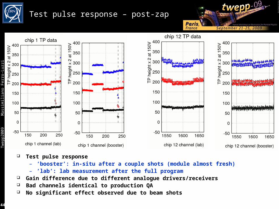
Test pulse response – post-zap
Test pulse response– ‘booster’: in-situ after a couple shots (module almost fresh)– ‘lab’: lab measurement after the full program
Gain difference due to different analogue drivers/receivers Bad channels identical to production QA No significant effect observed due to beam shots

Tw
epp2
009
M
assi
mili
ano
Fer
ro-L
uzzi
45
Voltage across the sensor vs. time
Oscilloscope measurements– Hybrid GND
– Backplane
– 1 sample / ns Ground reference arbitrary
– Huge ground bounce
– Large pick-up
– Plot Vbackplane-VhybridGND
Two distinct features– Sharp rising edge (50 ns)
– Slow charge-uptime [µs]

Tw
epp2
009
M
assi
mili
ano
Fer
ro-L
uzzi
46
The first 50 ns …
6 GV/s
time [µs]
2 GV/s
2.5 GV/s
Tw
epp2
009
M
assi
mili
ano
Fer
ro-L
uzzi
47
Shots on the FE chips
56 shots on the FE chips: 2x10⁹ – 2x10¹¹ p/bunch
No destructive latch-up– Design rules include structures to prevent latch-up– Seems to be effective!
SEU analysis in progress: none observed so far– Requires large energy deposited in small volume– Nuclear reactions necessary– Cross-section very low– Triple-redundant registers: corrected every 2 ns

Tw
epp2
009
M
assi
mili
ano
Fer
ro-L
uzzi
48
Summary of LHCb High Rate Test
The PS booster provided beam to emulate specific LHC beam injection failures– 200 ns shots (+/-2rms), 2x10⁹ to 9x10¹² protons in ~1cm2
A VELO strip module was subject to a large number of shots– Two positions on the sensor, five FE chips– Different conditions on LV and HV
Survived 9x10¹² p on sensor with 0, 150, 300 V bias, LV on or off Survived 2x10¹¹ p on the FE chip (LV on or off) No visible change in performance
– I/V curves, noise, pedestals, thermal imaging, … Saving graces ?
– The whole sensor responds as a unit– Large area sensor – many channels– CAC >> CRC (+CDET)– Protection diodes on the FE inputs– Triple-redundant registers in FE chips
Analysis & measurement still in progress

Tw
epp2
009
M
assi
mili
ano
Fer
ro-L
uzzi
49
Summary and Outlook
LHC is very different from what has been seen so far:– new (total beam) energy domain– cannot run without collimation (cryo/quenches)
Machine protection will play a key role (especially at turn-on)– passive (collimators) , active (beam interlocks, dump/inject)
Expts have developed own (to some extent, common) protection system– Beam Conditions Monitor (CVD diamonds) + other detectors => dump trigger– Should take care of circulating beam failures (redundant with machine protection)– Must have high availability, reliability, efficiency– Feed-back to stop injection is implemented– Close collaboration with machine colleagues
Not all possible failure scenarios for all IP's have been simulated or studied Not all exposed detectors have been stress-tested with high particle rates...
– Showed some recent results on LHCb/VELO damage threshold Full chain tests ongoing (some already done) Thresholds to be set and fine tuned with beam
Work in progressWork in progress

Tw
epp2
009
M
assi
mili
ano
Fer
ro-L
uzzi
50
Post-mortem – why did it survive?
Deposited energy (in 300 µm Si)
– 9x1012 x 24000 x 3.6 eV => 0.12 Joule in ~200 ns– Temperature increase in 1 cm2 x 0.3mm Si < ~ 2 ˚C – Maximum SPS injection train (288x1011): 0.4 Joule / 10 µs
Local energy store: the RC filter– 10 nF @ 300V => 0.5 mJ– Absorption volume critical
Massive ionisation in biased silicon– QRC(300V) = 3 µC
– Deposited charge @ 2x10⁹: 7.5 µC Possible transient damage
– Current through front-end– AC coupling diode– Voltage on front-end input– Fast HV ramp-down
vivum
HV bias reduced to 0 V