plasmarc cutting torches - esab.co.uk
TRANSCRIPT
Instruction Manual (EN)
PT-32EHPlasmarc Cutting Torches
0558003746
66
This equipment will perform in conformity with the description thereof contained in this manual and accompa-nying labels and/or inserts when installed, operated, maintained and repaired in accordance with the instruc-tions provided. This equipment must be checked periodically. Malfunctioning or poorly maintained equipment should not be used. Parts that are broken, missing, worn, distorted or contaminated should be replaced imme-diately. Should such repair or replacement become necessary, the manufacturer recommends that a telephone or written request for service advice be made to the Authorized Distributor from whom it was purchased.
This equipment or any of its parts should not be altered without the prior written approval of the manufacturer. The user of this equipment shall have the sole responsibility for any malfunction which results from improper use, faulty maintenance, damage, improper repair or alteration by anyone other than the manufacturer or a ser-vice facility designated by the manufacturer.
BE surE thIs INforMatIoN rEachEs thE opErator.You caN gEt Extra copIEs through Your supplIEr.
these INstructIoNs are for experienced operators. If you are not fully familiar with the principles of operation and safe practices for arc welding and cutting equipment, we urge you to read our booklet, “precautions and safe practices for arc Welding, cutting, and gouging,” form 52-529. Do Not permit untrained persons to install, operate, or maintain this equipment. Do Not attempt to install or operate this equipment until you have read and fully understand these instructions. If you do not fully understand these instructions, contact your supplier for further information. Be sure to read the safety precautions be-fore installing or operating this equipment.
cautIoN
usEr rEspoNsIBIlItY
rEaD aND uNDErstaND thE INstructIoN MaNual BEforE INstallINg or opEratINg.
protEct YoursElf aND othErs!
67
sEctIoN tItlE pagE
sEctIoN 1 safEtY ...............................................................................................................................................69
sEctIoN 2 DEscrIptIoN .......................................................................................................................................................................71 2.1 General .....................................................................................................................................................................................71 2.2 Scope ........................................................................................................................................................................................71 sEctIoN 3 INstallatIoN .....................................................................................................................................................................73 3.1 Fitting the PT-32EH Torch ..................................................................................................................................................73 3.2 Assembly .................................................................................................................................................................................74 sEctIoN 4 opEratIoN ...........................................................................................................................................................................75 4.1 Steel Heat Shield Guards ...................................................................................................................................................75 4.2 Cutting with the PT-32EH ..................................................................................................................................................76
sEctIoN 5 MaINtENaNcE ....................................................................................................................................................................81 5.1 Inspection and Cleaning of Consumables ..................................................................................................................81 5.2 Removing/Replacing Torch Head and Switch from Service Line ........................................................................82 sEctIoN 6 rEplacEMENt parts ......................................................................................................................................................83 6.1 General .....................................................................................................................................................................................83 6.2 Parts ..........................................................................................................................................................................................83
taBlE of coNtENts

68
taBlE of coNtENts
69
sEctIoN 1 safEtY prEcautIoNs
1.0 safety precautions
Users of ESAB welding and plasma cutting equipment have the ultimate responsibility for ensuring that anyone who works on or near the equipment observes all the relevant safety precautions. Safety precautions must meet the requirements that apply to this type of welding or plasma cutting equipment. The following recommendations should be observed in addition to the standard regulations that apply to the workplace.
All work must be carried out by trained personnel well acquainted with the operation of the welding or plasma cutting equipment. Incorrect operation of the equipment may lead to hazardous situations which can result in injury to the operator and damage to the equipment.
1. Anyone who uses welding or plasma cutting equipment must be familiar with: - its operation - location of emergency stops - its function - relevant safety precautions - welding and / or plasma cutting
2. The operator must ensure that: - no unauthorized person stationed within the working area of the equipment when it is started up. - no one is unprotected when the arc is struck.
3. The workplace must: - be suitable for the purpose - be free from drafts
4. Personal safety equipment: - Always wear recommended personal safety equipment, such as safety glasses, flame proof clothing, safety gloves. - Do not wear loose fitting items, such as scarves, bracelets, rings, etc., which could become trapped or cause burns.
5. General precautions: - Make sure the return cable is connected securely. - Work on high voltage equipment may only be carried out by a qualified electrician. - Appropriate fire extinquishing equipment must be clearly marked and close at hand. - Lubrication and maintenance must not be carried out on the equipment during operation.
70
sEctIoN 1 safEtY prEcautIoNs
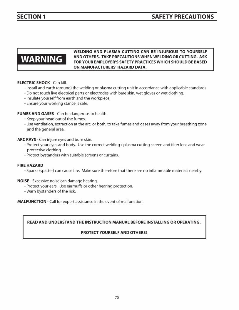
WElDINg aND plasMa cuttINg caN BE INJurIous to YoursElf aND othErs. taKE prEcautIoNs WhEN WElDINg or cuttINg. asK for Your EMploYEr’s safEtY practIcEs WhIch shoulD BE BasED oN MaNufacturErs’ haZarD Data.
ElEctrIc shocK - Can kill. - Install and earth (ground) the welding or plasma cutting unit in accordance with applicable standards. - Do not touch live electrical parts or electrodes with bare skin, wet gloves or wet clothing. - Insulate yourself from earth and the workpiece. - Ensure your working stance is safe.
fuMEs aND gasEs - Can be dangerous to health. - Keep your head out of the fumes. - Use ventilation, extraction at the arc, or both, to take fumes and gases away from your breathing zone and the general area.
arc raYs - Can injure eyes and burn skin. - Protect your eyes and body. Use the correct welding / plasma cutting screen and filter lens and wear protective clothing. - Protect bystanders with suitable screens or curtains.
fIrE haZarD - Sparks (spatter) can cause fire. Make sure therefore that there are no inflammable materials nearby.
NoIsE - Excessive noise can damage hearing. - Protect your ears. Use earmuffs or other hearing protection. - Warn bystanders of the risk.
MalfuNctIoN - Call for expert assistance in the event of malfunction.
rEaD aND uNDErstaND thE INstructIoN MaNual BEforE INstallINg or opEratINg.
protEct YoursElf aND othErs!
WarNINg
71
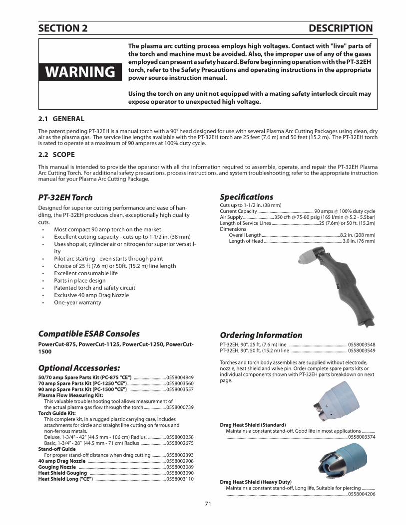
PT-32EH TorchDesigned for superior cutting performance and ease of han-dling, the PT-32EH produces clean, exceptionally high quality cuts.
Most compact 90 amp torch on the market•Excellent cutting capacity - cuts up to 1-1/2 in. (38 mm)•Uses shop air, cylinder air or nitrogen for superior versatil-•ityPilot arc starting - even starts through paint•Choice of 25 ft (7.6 m) or 50ft. (15.2 m) line length•Excellent consumable life•Parts in place design•Patented torch and safety circuit•Exclusive 40 amp Drag Nozzle•One-year warranty•
Ordering InformationPT-32EH, 90°, 25 ft. (7.6 m) line .................................................... 0558003548PT-32EH, 90°, 50 ft. (15.2 m) line .................................................. 0558003549
Torches and torch body assemblies are supplied without electrode, nozzle, heat shield and valve pin. Order complete spare parts kits or individual components shown with PT-32EH parts breakdown on next page.
sEctIoN 2 DEscrIptIoN
Optional Accessories:50/70 amp spare parts Kit (pc-875 "cE") ............................. 055800494970 amp spare parts Kit (pc-1250 "cE") ................................... 055800356090 amp spare parts Kit (pc-1500 "cE") ................................. 0558003557plasma flow Measuring Kit: This valuable troubleshooting tool allows measurement of the actual plasma gas flow through the torch .................... 0558000739torch guide Kit: This complete kit, in a rugged plastic carrying case, includes attachments for circle and straight line cutting on ferrous and non-ferrous metals. Deluxe, 1-3/4" - 42" (44.5 mm - 106 cm) Radius, ................ 0558003258 Basic, 1-3/4” - 28” (44.5 mm - 71 cm) Radius ....................... 0558002675stand-off guide For proper stand-off distance when drag cutting ............. 055800239340 amp Drag Nozzle ....................................................................... 0558002908gouging Nozzle ............................................................................... 0558003089heat shield gouging ..................................................................... 0558003090heat shield long ("cE") ................................................................ 0558003110
Drag heat shield (standard) Maintains a constant stand-off, Good life in most applications ............ .............................................................................................................. 0558003374
Drag heat shield (heavy Duty) Maintains a constant stand-off, Long life, Suitable for piercing ............ .............................................................................................................. 0558004206
2.1 gENEral
The patent pending PT-32EH is a manual torch with a 90° head designed for use with several Plasma Arc Cutting Packages using clean, dry air as the plasma gas. The service line lengths available with the PT-32EH torch are 25 feet (7.6 m) and 50 feet (15.2 m). The PT-32EH torch is rated to operate at a maximum of 90 amperes at 100% duty cycle.
2.2 scopE
This manual is intended to provide the operator with all the information required to assemble, operate, and repair the PT-32EH Plasma Arc Cutting Torch. For additional safety precautions, process instructions, and system troubleshooting; refer to the appropriate instruction manual for your Plasma Arc Cutting Package.
the plasma arc cutting process employs high voltages. contact with "live" parts of the torch and machine must be avoided. also, the improper use of any of the gases employed can present a safety hazard. Before beginning operation with the pt-32Eh torch, refer to the safety precautions and operating instructions in the appropriate power source instruction manual.
using the torch on any unit not equipped with a mating safety interlock circuit may expose operator to unexpected high voltage.
WarNINg
SpecificationsCuts up to 1-1/2 in. (38 mm)Current Capacity ................................................... 90 amps @ 100% duty cycleAir Supply ............................350 cfh @ 75-80 psig (165 l/min @ 5.2 - 5.5bar)Length of Service Lines ...........................................25 (7.6m) or 50 ft. (15.2m)Dimensions Overall Length .......................................................................8.2 in. (208 mm) Length of Head ....................................................................... 3.0 in. (76 mm)
Compatible ESAB Consolespowercut-875, powercut-1125, powercut-1250, powercut-1500
72
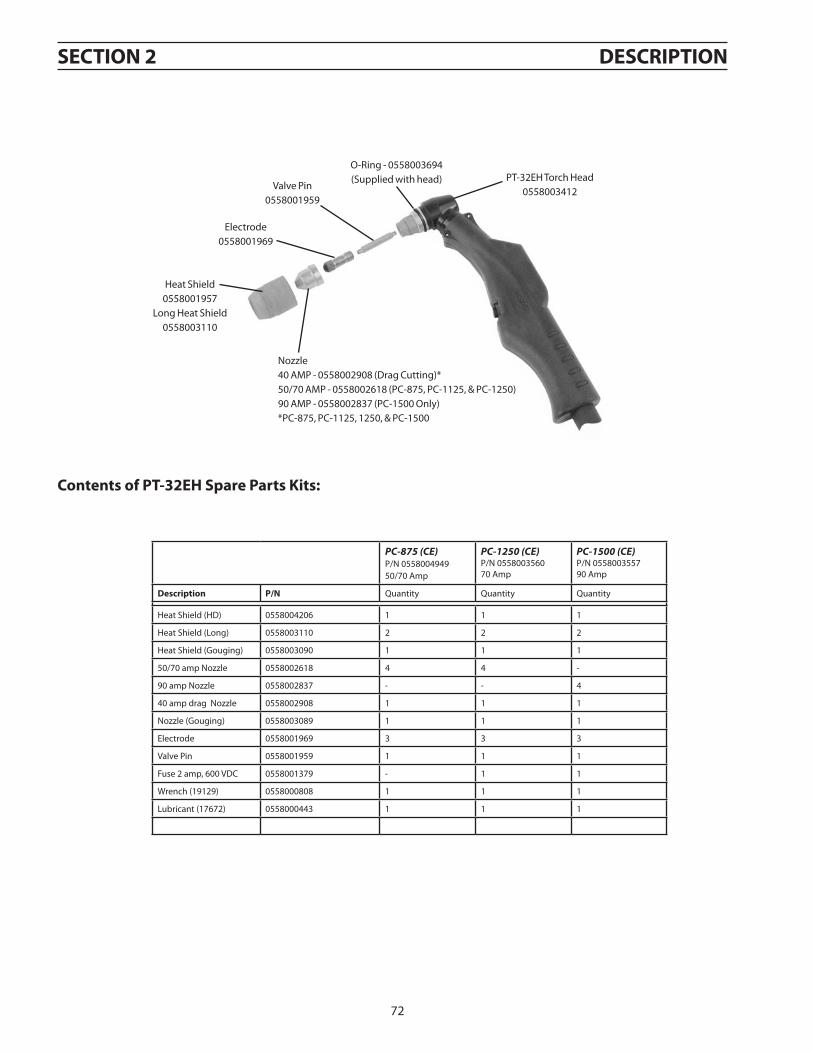
Heat Shield0558001957
Long Heat Shield0558003110
Valve Pin0558001959
O-Ring - 0558003694(Supplied with head)
Electrode0558001969
Nozzle40 AMP - 0558002908 (Drag Cutting)*50/70 AMP - 0558002618 (PC-875, PC-1125, & PC-1250)90 AMP - 0558002837 (PC-1500 Only)*PC-875, PC-1125, 1250, & PC-1500
PT-32EH Torch Head0558003412
contents of pt-32Eh spare parts Kits:
sEctIoN 2 DEscrIptIoN
PC-875 (CE) P/N 0558004949 50/70 Amp
PC-1250 (CE) P/N 0558003560 70 Amp
PC-1500 (CE) P/N 055800355790 Amp
Description p/N Quantity Quantity Quantity
Heat Shield (HD) 0558004206 1 1 1
Heat Shield (Long) 0558003110 2 2 2
Heat Shield (Gouging) 0558003090 1 1 1
50/70 amp Nozzle 0558002618 4 4 -
90 amp Nozzle 0558002837 - - 4
40 amp drag Nozzle 0558002908 1 1 1
Nozzle (Gouging) 0558003089 1 1 1
Electrode 0558001969 3 3 3
Valve Pin 0558001959 1 1 1
Fuse 2 amp, 600 VDC 0558001379 - 1 1
Wrench (19129) 0558000808 1 1 1
Lubricant (17672) 0558000443 1 1 1
73
sEctIoN 3 INstallatIoN
3.1 fIttINg thE pt-32Eh torch
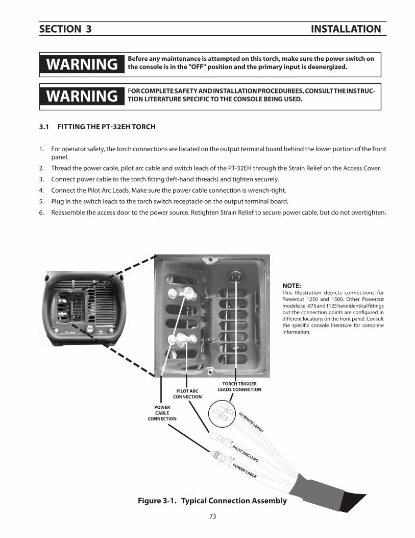
1. For operator safety, the torch connections are located on the output terminal board behind the lower portion of the front panel.
2. Thread the power cable, pilot arc cable and switch leads of the PT-32EH through the Strain Relief on the Access Cover.
3. Connect power cable to the torch fitting (left-hand threads) and tighten securely.
4. Connect the Pilot Arc Leads. Make sure the power cable connection is wrench-tight.
5. Plug in the switch leads to the torch switch receptacle on the output terminal board.
6. Reassemble the access door to the power source. Retighten Strain Relief to secure power cable, but do not overtighten.
poWEr caBlE
pIlot arc lEaD
(2) WhItE lEaDs
poWErcaBlE
coNNEctIoN
pIlot arccoNNEctIoN
torch trIggErlEaDs coNNEctIoN
figure 3-1. typical connection assembly
For coMplEtE safEtY aND INstallatIoN procEDurEEs, coNsult thE INstruc-tIoN lItEraturE spEcIfIc to thE coNsolE BEINg usED.
NotE:This Illustration depicts connections for Powercut 1250 and 1500. Other Powercut models; i.e., 875 and 1125 have identical fittings but the connection points are configured in different locations on the front panel. Consult the specific console literature for complete information.
Before any maintenance is attempted on this torch, make sure the power switch on the console is in the "off" position and the primary input is deenergized.WarNINg
WarNINg
74
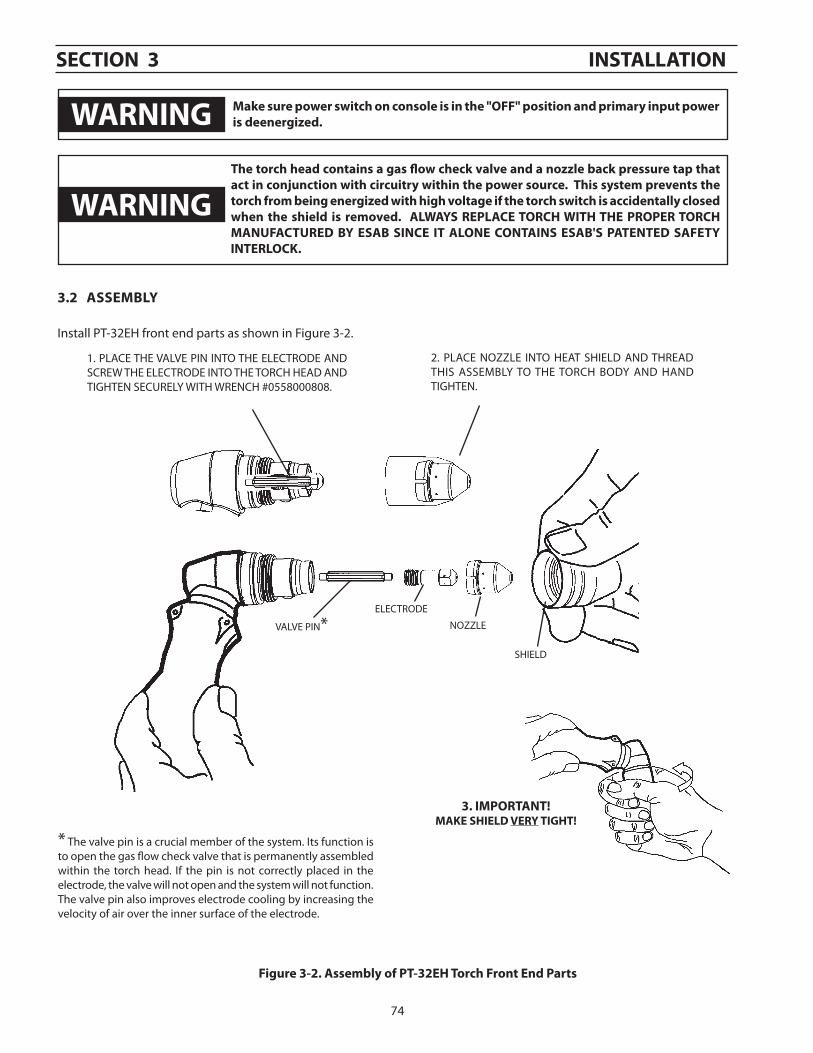
3.2 assEMBlY
Install PT-32EH front end parts as shown in Figure 3-2.
the torch head contains a gas flow check valve and a nozzle back pressure tap that act in conjunction with circuitry within the power source. this system prevents the torch from being energized with high voltage if the torch switch is accidentally closed when the shield is removed. alWaYs rEplacE torch WIth thE propEr torch MaNufacturED BY EsaB sINcE It aloNE coNtaINs EsaB's patENtED safEtY INtErlocK.
sEctIoN 3 INstallatIoN
* The valve pin is a crucial member of the system. Its function is to open the gas flow check valve that is permanently assembled within the torch head. If the pin is not correctly placed in the electrode, the valve will not open and the system will not function. The valve pin also improves electrode cooling by increasing the velocity of air over the inner surface of the electrode.
2. PLACE NOZZLE INTO HEAT SHIELD AND THREAD THIS ASSEMBLY TO THE TORCH BODY AND HAND TIGHTEN.
1. PLACE THE VALVE PIN INTO THE ELECTRODE AND SCREW THE ELECTRODE INTO THE TORCH HEAD AND TIGHTEN SECURELY WITH WRENCH #0558000808.
figure 3-2. assembly of pt-32Eh torch front End parts
SHIELD
VALVE PIN*ELECTRODE
NOZZLE
3. IMportaNt!MaKE shIElD VErY tIght!
WarNINg Make sure power switch on console is in the "off" position and primary input power is deenergized.
WarNINg
75
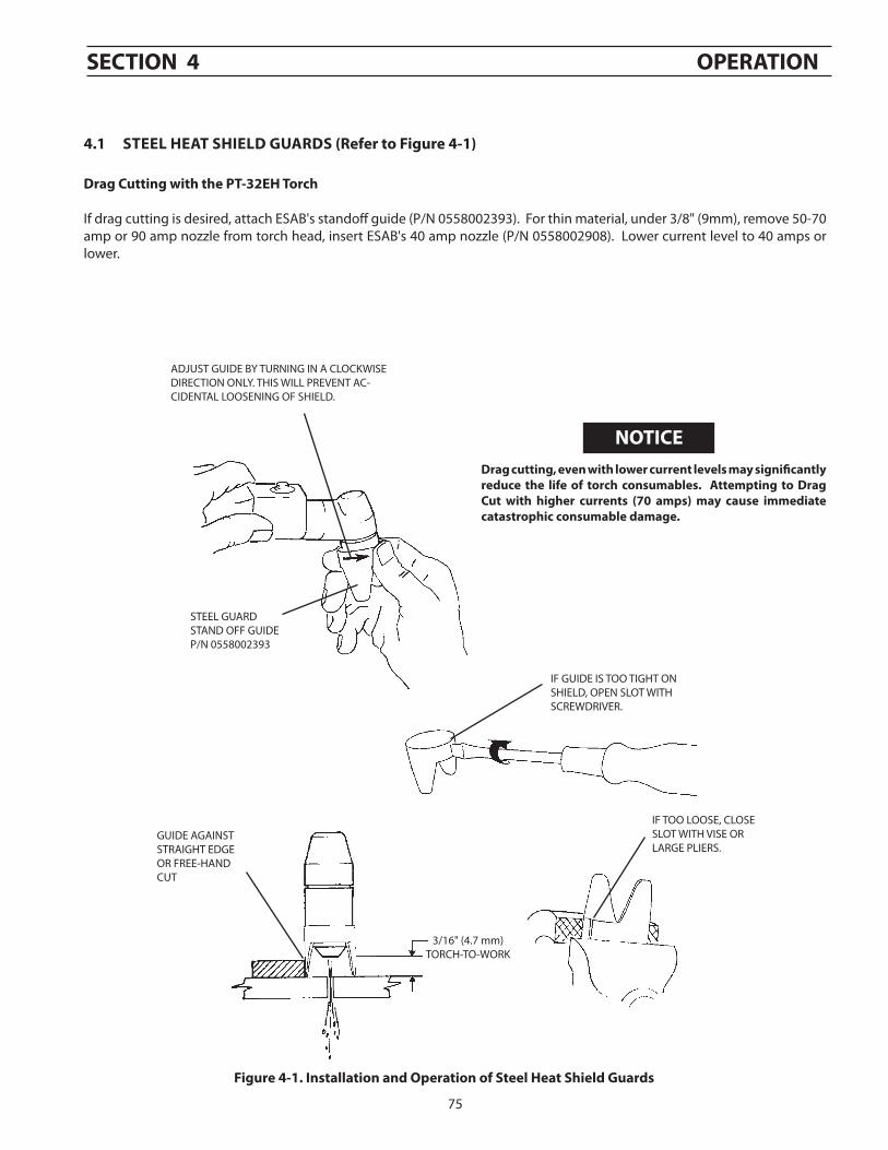
4.1 stEEl hEat shIElD guarDs (refer to figure 4-1)
ADJUST GUIDE BY TURNING IN A CLOCKWISE DIRECTION ONLY. THIS WILL PREVENT AC-CIDENTAL LOOSENING OF SHIELD.
STEEL GUARDSTAND OFF GUIDEP/N 0558002393
IF GUIDE IS TOO TIGHT ON SHIELD, OPEN SLOT WITH SCREWDRIVER.
IF TOO LOOSE, CLOSESLOT WITH VISE ORLARGE PLIERS.
3/16" (4.7 mm) TORCH-TO-WORK
GUIDE AGAINSTSTRAIGHT EDGEOR FREE-HANDCUT
figure 4-1. Installation and operation of steel heat shield guards
Drag cutting, even with lower current levels may significantly reduce the life of torch consumables. attempting to Drag cut with higher currents (70 amps) may cause immediate catastrophic consumable damage.
Drag cutting with the pt-32Eh torch
If drag cutting is desired, attach ESAB's standoff guide (P/N 0558002393). For thin material, under 3/8" (9mm), remove 50-70 amp or 90 amp nozzle from torch head, insert ESAB's 40 amp nozzle (P/N 0558002908). Lower current level to 40 amps or lower.
sEctIoN 4 opEratIoN
NotIcE
76
sEctIoN 4 opEratIoN
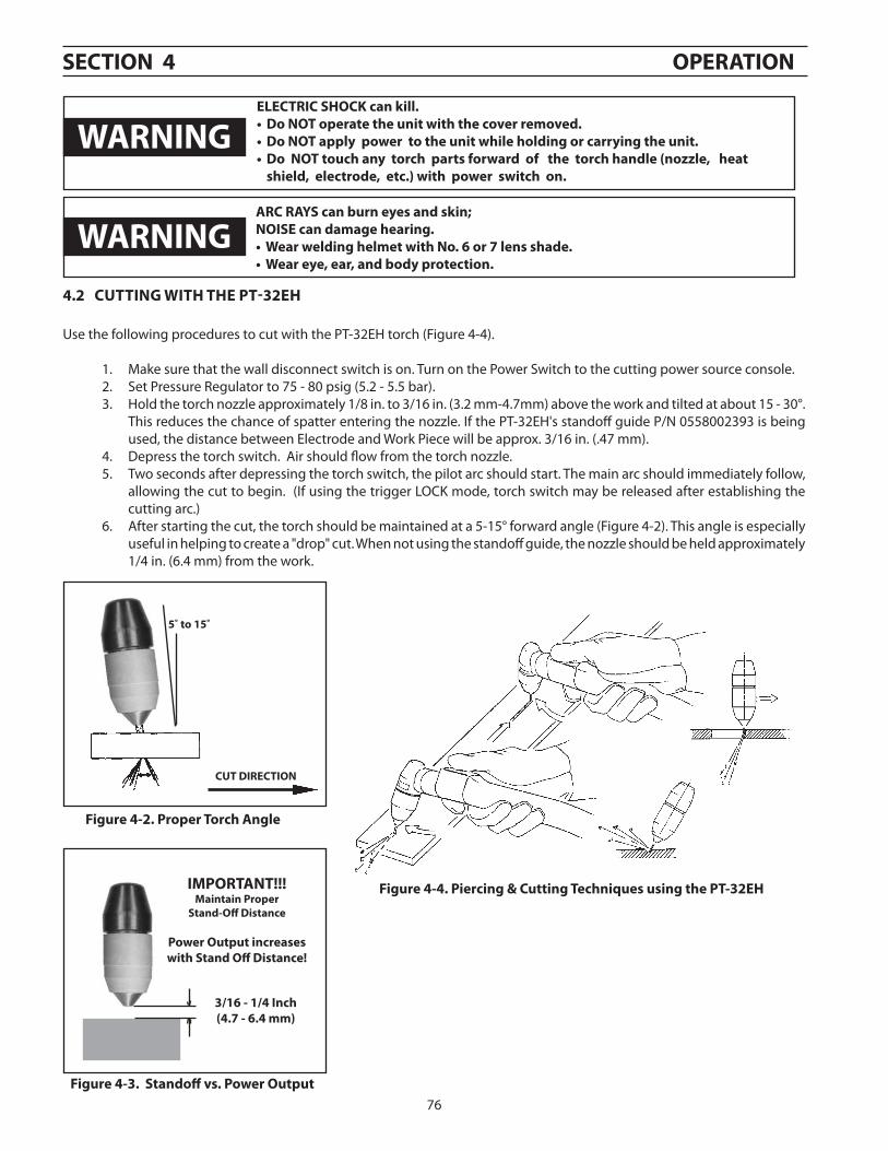
4.2 cuttINg WIth thE pt-32Eh
Use the following procedures to cut with the PT-32EH torch (Figure 4-4).
1. Make sure that the wall disconnect switch is on. Turn on the Power Switch to the cutting power source console.2. Set Pressure Regulator to 75 - 80 psig (5.2 - 5.5 bar).3. Hold the torch nozzle approximately 1/8 in. to 3/16 in. (3.2 mm-4.7mm) above the work and tilted at about 15 - 30°.
This reduces the chance of spatter entering the nozzle. If the PT-32EH's standoff guide P/N 0558002393 is being used, the distance between Electrode and Work Piece will be approx. 3/16 in. (.47 mm).
4. Depress the torch switch. Air should flow from the torch nozzle.5. Two seconds after depressing the torch switch, the pilot arc should start. The main arc should immediately follow,
allowing the cut to begin. (If using the trigger LOCK mode, torch switch may be released after establishing the cutting arc.)
6. After starting the cut, the torch should be maintained at a 5-15° forward angle (Figure 4-2). This angle is especially useful in helping to create a "drop" cut. When not using the standoff guide, the nozzle should be held approximately 1/4 in. (6.4 mm) from the work.
ElEctrIc shocK can kill.•DoNOToperatetheunitwiththecoverremoved.•DoNOTapplypowertotheunitwhileholdingorcarryingtheunit.•DoNOTtouchanytorchpartsforwardofthetorchhandle(nozzle,heat
shield, electrode, etc.) with power switch on.
figure 4-2. proper torch angle
figure 4-3. standoff vs. power output
IMportaNt!!!Maintain proper
stand-off Distance
power output increases with stand off Distance!
3/16 - 1/4 Inch(4.7 - 6.4 mm)
figure 4-4. piercing & cutting techniques using the pt-32Eh
cut DIrEctIoN
5˚ to 15˚
WarNINg
WarNINgarc raYs can burn eyes and skin;NoIsE can damage hearing.•WearweldinghelmetwithNo.6or7lensshade.•Weareye,ear,andbodyprotection.
77
sEctIoN 4 opEratIoN
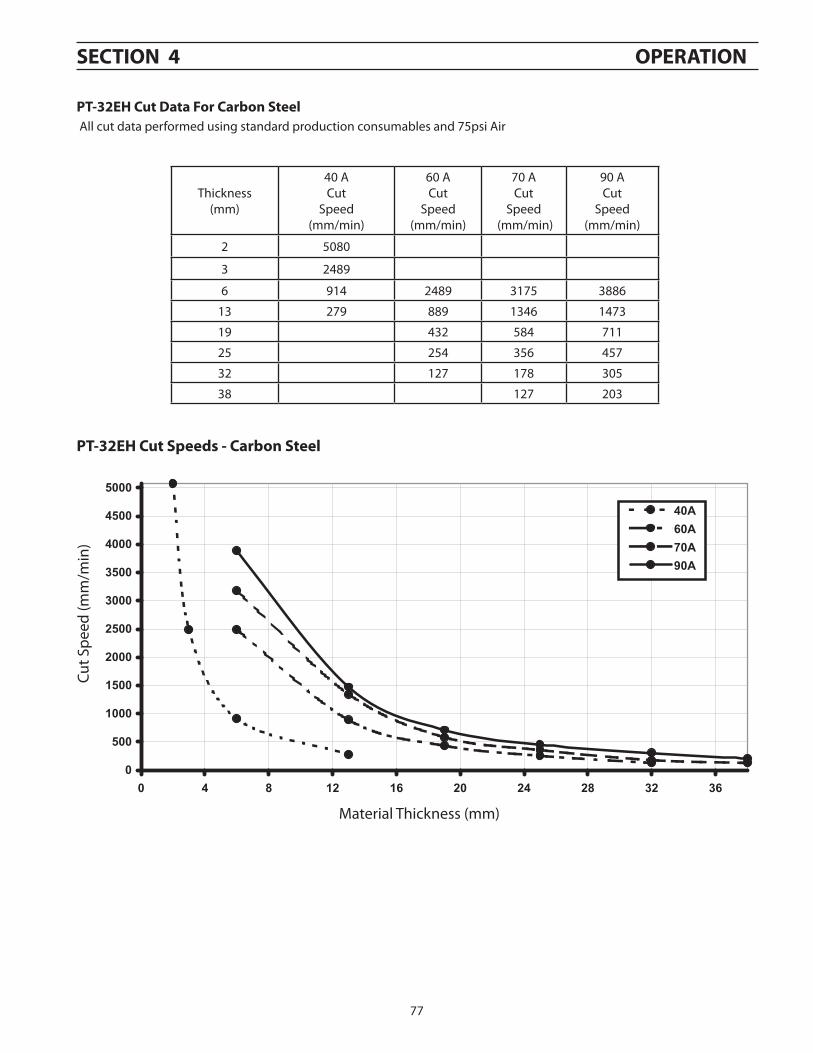
pt-32Eh cut speeds - carbon steel
Cut S
peed
(mm
/min
)
Material Thickness (mm)
Thickness(mm)
40 ACut
Speed (mm/min)
60 ACut
Speed (mm/min)
70 A Cut
Speed (mm/min)
90 ACut
Speed (mm/min)
2 5080
3 2489
6 914 2489 3175 3886
13 279 889 1346 1473
19 432 584 711
25 254 356 457
32 127 178 305
38 127 203
pt-32Eh cut Data for carbon steel All cut data performed using standard production consumables and 75psi Air
0
500
1000
1500
2000
2500
3000
3500
4000
4500
5000
0 4 8 12 16 20 24 28 32 36
40A60A70A90A
0
500
1000
1500
2000
2500
3000
3500
4000
4500
5000
0 4 8 12 16 20 24 28 32 36
40A60A70A90A
0
500
1000
1500
2000
2500
3000
3500
4000
4500
5000
0 4 8 12 16 20 24 28 32 36
40A60A70A90A
78
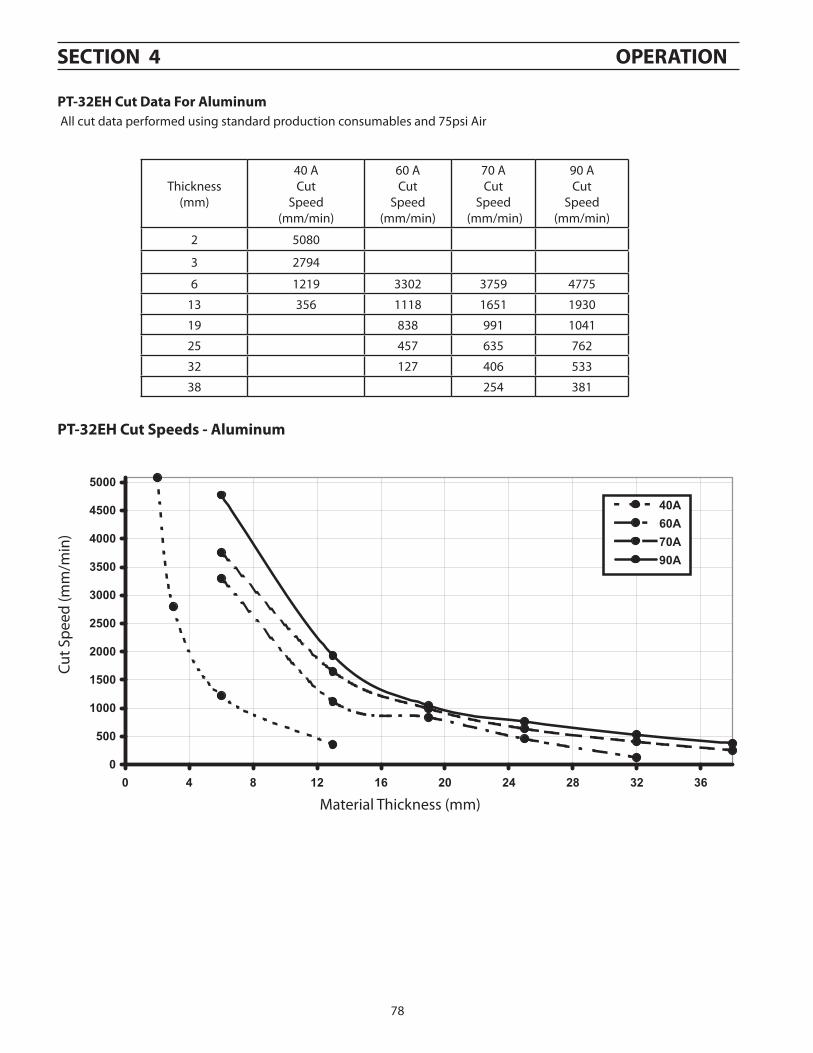
pt-32Eh cut speeds - aluminum
Thickness(mm)
40 ACut
Speed (mm/min)
60 ACut
Speed (mm/min)
70 A Cut
Speed (mm/min)
90 ACut
Speed (mm/min)
2 5080
3 2794
6 1219 3302 3759 4775
13 356 1118 1651 1930
19 838 991 1041
25 457 635 762
32 127 406 533
38 254 381
pt-32Eh cut Data for aluminum All cut data performed using standard production consumables and 75psi Air
0
500
1000
1500
2000
2500
3000
3500
4000
4500
5000
0 4 8 12 16 20 24 28 32 36
40A60A70A90A
0
500
1000
1500
2000
2500
3000
3500
4000
4500
5000
0 4 8 12 16 20 24 28 32 36
40A60A70A90A
0
500
1000
1500
2000
2500
3000
3500
4000
4500
5000
0 4 8 12 16 20 24 28 32 36
40A60A70A90A
Cut S
peed
(mm
/min
)
Material Thickness (mm)
sEctIoN 4 opEratIoN
79
Thickness(mm)
40 ACut
Speed (mm/min)
60 ACut
Speed (mm/min)
70 A Cut
Speed (mm/min)
90 ACut
Speed (mm/min)
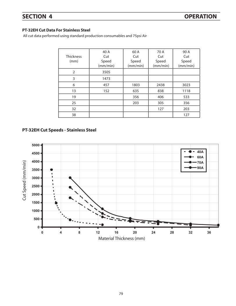
2 3505
3 1473
6 457 1803 2438 3023
13 152 635 838 1118
19 356 406 533
25 203 305 356
32 127 203
38 127
pt-32Eh cut Data for stainless steel All cut data performed using standard production consumables and 75psi Air
0
500
1000
1500
2000
2500
3000
3500
4000
4500
5000
0 4 8 12 16 20 24 28 32 36
40A60A70A90A
0
500
1000
1500
2000
2500
3000
3500
4000
4500
5000
0 4 8 12 16 20 24 28 32 36
40A60A70A90A
0
500
1000
1500
2000
2500
3000
3500
4000
4500
5000
0 4 8 12 16 20 24 28 32 36
40A60A70A90A
pt-32Eh cut speeds - stainless steel
Cut S
peed
(mm
/min
)
Material Thickness (mm)
sEctIoN 4 opEratIoN

80
sEctIoN 4 opEratIoN
81
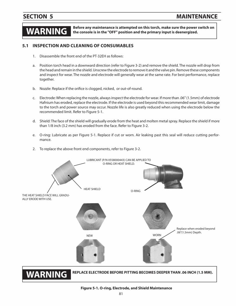
5.1 INspEctIoN aND clEaNINg of coNsuMaBlEs
1. Disassemble the front end of the PT-32EH as follows:
a. Position torch head in a downward direction (refer to Figure 3-2) and remove the shield. The nozzle will drop from the head and remain in the shield. Unscrew the electrode to remove it and the valve pin. Remove these components and inspect for wear. The nozzle and electrode will generally wear at the same rate. For best performance, replace together.
b. Nozzle: Replace if the orifice is clogged, nicked, or out-of-round.
c. Electrode: When replacing the nozzle, always inspect the electrode for wear. If more than .06" (1.5mm) of electrode Hafnium has eroded, replace the electrode. If the electrode is used beyond this recommended wear limit, damage to the torch and power source may occur. Nozzle life is also greatly reduced when using the electrode below the recommended limit. Refer to Figure 5-1.
d. Shield: The face of the shield will gradually erode from the heat and molten metal spray. Replace the shield if more than 1/8 inch (3.2 mm) has eroded from the face. Refer to Figure 3-2.
e. O-ring: Lubricate as per Figure 5-1. Replace if cut or worn. Air leaking past this seal will reduce cutting perfor-mance.
2. To replace the above front end components, refer to Figure 3-2.
HEAT SHIELD
figure 5-1. o-ring, Electrode, and shield Maintenance
LUBRICANT (P/N 0558000443) CAN BE APPLIED TO O-RING OR HEAT SHIELD.
THE HEAT SHIELD FACE WILL GRADU-ALLY ERODE WITH USE.
O-RING
rEplacE ElEctroDE BEforE pIttINg BEcoMEs DEEpEr thaN .06 INch (1.5 MM).
NEW
Replace when eroded beyond.06"(1.5mm) Depth.
WORN
sEctIoN 5 MaINtENaNcE
WarNINg Before any maintenance is attempted on this torch, make sure the power switch on the console is in the "off" position and the primary input is deenergized.
WarNINg
82
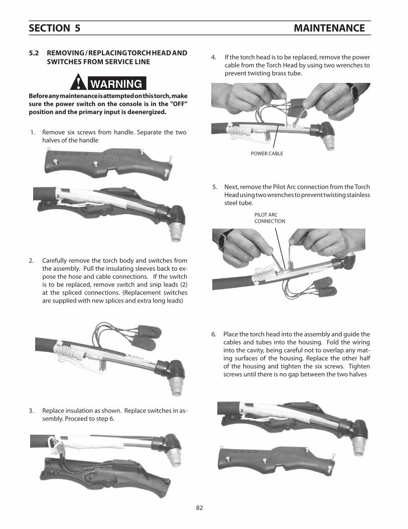
5.2 rEMoVINg / rEplacINg torch hEaD aND sWItchEs froM sErVIcE lINE
5. Next, remove the Pilot Arc connection from the Torch Head using two wrenches to prevent twisting stainless steel tube.
POWER CABLE
PILOT ARC CONNECTION
4. If the torch head is to be replaced, remove the power cable from the Torch Head by using two wrenches to prevent twisting brass tube.
sEctIoN 5 MaINtENaNcE
2. Carefully remove the torch body and switches from the assembly. Pull the insulating sleeves back to ex-pose the hose and cable connections. If the switch is to be replaced, remove switch and snip leads (2) at the spliced connections. (Replacement switches are supplied with new splices and extra long leads)
3. Replace insulation as shown. Replace switches in as-sembly. Proceed to step 6.
1. Remove six screws from handle. Separate the two halves of the handle
6. Place the torch head into the assembly and guide the cables and tubes into the housing. Fold the wiring into the cavity, being careful not to overlap any mat-ing surfaces of the housing. Replace the other half of the housing and tighten the six screws. Tighten screws until there is no gap between the two halves
Before any maintenance is attempted on this torch, make sure the power switch on the console is in the "off" position and the primary input is deenergized.
83
sEctIoN 6 rEplacEMENt parts
6.1 general
Always provide the serial number of the unit on which the parts will be used. The serial number is stamped on the unit nameplate.
To ensure proper operation, it is recommended that only genuine ESAB parts and products be used with this equipment. The use of non-ESAB parts may void your warranty.
Replacement parts may be ordered from your ESAB Distributor.
Be sure to indicate any special shipping instructions when ordering replacement parts.
Refer to the Communications Guide located on the back page of this manual for a list of customer service phone numbers.
6.2 ordering
Bill of material items that have blank part numbers are provided for customer information only. Hardware items should be available through local sources.
Note
6.0 replacement parts
84
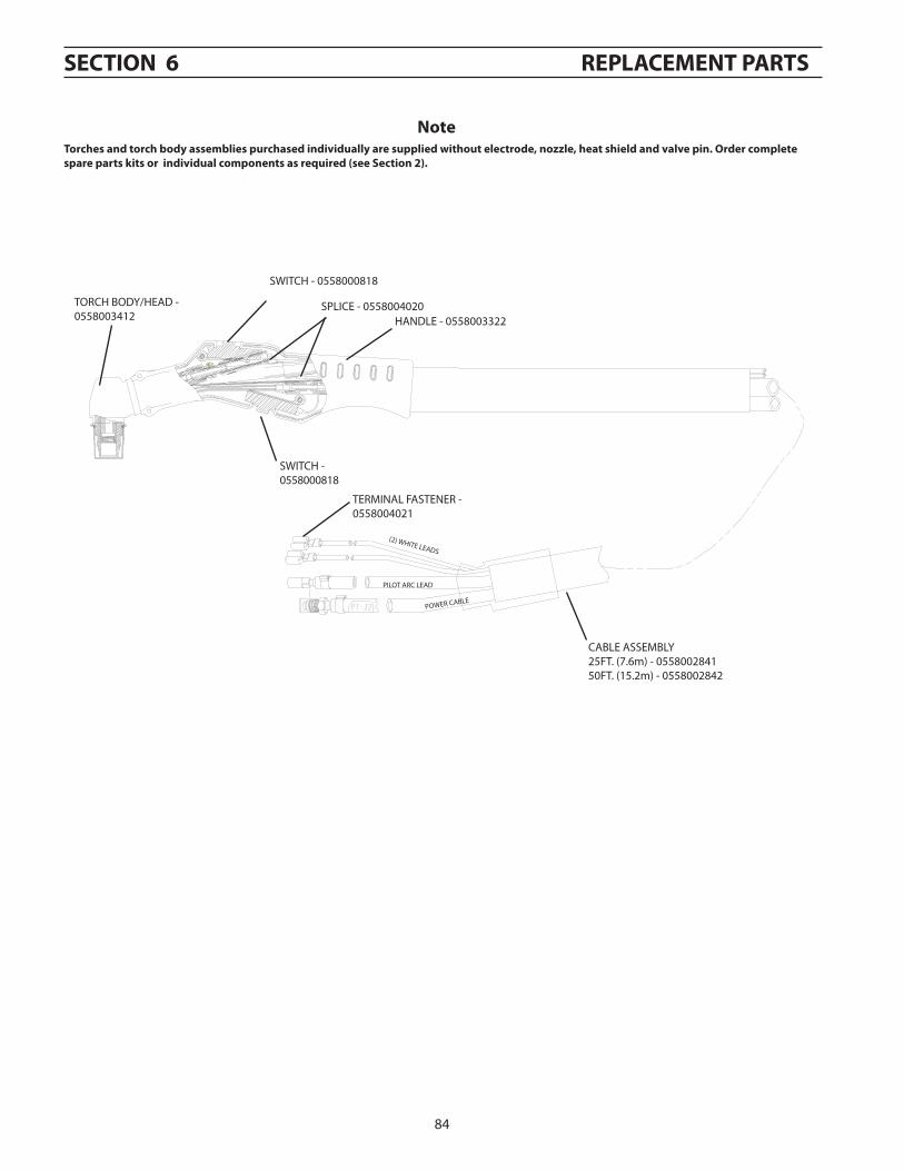
TORCH BODY/HEAD - 0558003412
SWITCH - 0558000818
HANDLE - 0558003322SPLICE - 0558004020
SWITCH -0558000818
TERMINAL FASTENER - 0558004021
(2) WHITE LEADS
PILOT ARC LEAD
POWER CABLE
CABLE ASSEMBLY25FT. (7.6m) - 055800284150FT. (15.2m) - 0558002842
torches and torch body assemblies purchased individually are supplied without electrode, nozzle, heat shield and valve pin. order complete spare parts kits or individual components as required (see section 2).
sEctIoN 6 rEplacEMENt parts
Note