plasmonic electromagnetically-induced transparency in symmetric structures
TRANSCRIPT

Plasmonic electromagnetically-inducedtransparency in symmetric structures
Xingri Jin,1 Yuehui Lu,1 Haiyu Zheng,1 YoungPak Lee,1,∗ Joo YullRhee2,4 and Won Ho Jang3
1Quantum Photonic Science Research Center and Department of Physics, HanyangUniversity, Seoul 133-791, Republic of Korea
2Department of Physics, Sungkyunkwan University, Suwon 440-746, Republic of Korea3Korea Communication Commission Radio Research Laboratory, Seoul 140-848, Republic of
∗Corresponding author: [email protected]
Abstract: A broken symmetry is generally believed to be a prerequisitefor plasmonic electromagnetically-induced transparency (EIT), since theasymmetry allows the excitation of the otherwise forbidden dark mode.Nevertheless, according to the picture of magnetic plasmon resonance(MPR)-mediated plasmonic EIT, we show that plasmonic EIT can beachieved even in symmetric structures, provided that we take into accountthe plasmonic modes beyond the fundamental ones. This not only sharpensour understanding of the existing concept, but also provides a profoundinsight into the plasmonic coherent interference in the near-field zone.
© 2010 Optical Society of America
OCIS codes: (160.3918) Metamaterials; (260.5740) Resonators; (260.2110) Electromagneticoptics.
References and links1. K.-J. Boller, A. Imamoglu, and S. E. Harris, “Observation of electromagnetically induced transparency,” Phys.
Rev. Lett. 66, 2593 (1991).2. S. E. Harris, “Electromagnetically induced transparency,” Phys. Today 50, 36 (1997).3. M. Fleischhauer, A. Imamoglu, and J. P. Marangos, “Electromagnetically induced transparency: optics in coher-
ent media,” Rev. Mod. Phys. 77, 633 (2005).4. M. D. Lukin, S. F. Yelin, and M. Fleischhauer, “Entanglement of atomic ensembles by trapping correlated photon
states,” Phys. Rev. Lett. 84, 4232 (2000).5. S. E. Harris and L. V. Hau, “Nonlinear optics at low light levels,” Phys. Rev. Lett. 82, 4611 (1999).6. L. V. Hau, S. E. Harris, Z. Dutton, and C. H. Behroozi, “Light speed reduction to 17 metres per second in an
ultracold atomicgas,” Nature (London) 397, 594 (1999).7. C. L. G. Alzer, M. A. G. Martinez, and P. Nussenzveig, “Classical analog of electromagnetically induced trans-
parency,” Am. J. Phys. 70, 37 (2002).8. T. Opatrny and D.-G. Welsch, “Coupled cavities for enhancing the cross-phase-modulation in electromagneti-
cally induced transparency,” Phys. Rev. A 64, 023805 (2001).9. D. D. Smith, H. Chang, K. A. Fuller, A. T. Rosenberger, and R. W. Boyd, “Coupled-resonator-induced trans-
parency,” Phys. Rev. A 69, 063804 (2004).10. A. Naweed, G. Farca, S. I. Shopova, and A. T. Rosenberger, “Induced transparency and absorption in coupled
whispering-gallery microresonators,” Phys. Rev. A 71, 043804 (2005).11. L. Maleki, A. B. Matsko, A. A. Savchenkov, and V. S. Ilchenko,“Tunable delay line with interacting whispering-
gallery-mode resonators,” Opt. Lett. 29, 626 (2004).12. Q. Xu, S. Sandhu, M. L. Povinelli, J. Shakya, S. Fan, and M. Lipson, “Experimental realization of an on-chip
all-optical analogue to electromagnetically induced transparency,” Phys. Rev. Lett. 96, 123901 (2006).13. S. Zhang, D. A. Genov, Y. Wang, M. Liu, and X. Zhang, “Plasmon-induced transparency in metamaterials,”
Phys. Rev. Lett. 101, 047401 (2008).
#127577 - $15.00 USD Received 27 Apr 2010; revised 4 Jun 2010; accepted 4 Jun 2010; published 7 Jun 2010(C) 2010 OSA 21 June 2010 / Vol. 18, No. 13 / OPTICS EXPRESS 13396
14. H. Xu, and B. S. Ham, “Plasmon-induced photonic switching in a metamaterial,” arXiv:0905.3102v4[quant-ph].
15. Y. Lu, H. Xu, N. T. Tung, J. Y. Rhee, W. H. Jang, B. S. Ham, and Y. P. Lee, “Role of mag-netic plasmon resonance in plasmonic electromagnetically-induced transparency,” arXiv:0906.4029v4[cond-mat.mtrl-sci].
16. N. Liu, L. Langguth, T. Weiss, J. Kastel, M. Fleischhauer, T. Pfau, and H. Giessen, “Plasmonic analogue ofelectromagnetically induced transparency at the Drude damping limit,” Nature Mater. 8, 758 (2009).
17. X.-R. Su, Z.-S. Zhang, L.-H. Zhang, Q.-Q. Li, C.-C. Chen, Z.-J. Yang, and Q.-Q. Wang, “Plasmonic interferencesand optical modulations in dark-bringt-dark plasmon resonators,” Appl. Phys. Lett. 96, 043113 (2010).
18. N. Papasimakis, V. A. Fedotov, N. I. Zheludev, and S. L. Prosvirnin, “Metamaterial analog of electromagneticallyinduced transparency,” Phys. Rev. Lett. 101, 253903 (2008).
19. N. Papasimakis, Y. H. Fu, V. A. Fedotov, S. L. Prosvirnin, D. P. Tsai, and N. I. Zheludev, “Metamaterial withpolarization and direction insensitive resonant transmission response mimicking electromagnetically inducedtransparency,” Appl. Phys. Lett. 94, 211902 (2009).
20. P. Tassin, L. Zhang, T. Koschny, E. N. Economou, and C. M. Soukoulis, “Low-Loss Metamaterials Based onClassical Electromagnetically Induced Transparency,” Phys. Rev. Lett. 102, 053901 (2009).
21. P. Tassin, L. Zhang, T. Koschny, E. N. Economou, and C. M. Soukoulis, “Planar designs for electromagneticallyinduced transparency in metamaterials,” Opt. Express 17, 5595 (2009).
22. R. Singh, C. Rockstuhl, F. Lederer, and W. L. Zhang, “Coupling between a dark and a bright eigenmode in aterahertz metamaterial,” Phys. Rev. B 79, 085111 (2009).
23. V. Yannopapas, E. Paspalakis, and N. V. Vitanov, “Electromagnetically induced transparency and slow light inan array of metallic nanoparticles,” Phys. Rev. B 80, 035104 (2009).
24. E. Prodan, C. Radloff, N. J. Halas, and P. Nordlander, “A hybridization model for the plasmon response ofcomplex nanostructures,” Science 302, 419 (2003).
25. F. Hao, Y. Sonnefraud, P. V. Dorpe, S. A. Maier, N. J. Halas, and P. Nordlander, “Symmetry breaking in plasmonicnanocavities: subradiant LSPR sensing and a tunable Fano resonance,” Nano Lett. 8, 3983 (2008).
26. G. Dolling, C. Enkrich, M. Wegener, C. M. Soukoulis, and S. Linden, “Simultaneous negative phase and groupvelocity of light in a metamaterial,” Science 312, 892 (2006).
27. S. Zhang, W. J. Fan, K. J. Malloy, S. R. J. Brueck, N. C. Panoiu, and R. M. Osgood, “Demonstration of metal-dielectric negative-index metamaterials with improved performance at optical frequencies,” J. Opt. Soc. Am. B23, 434 (2006).
28. L. Novotny, “Effective wavelength scaling for optical antennas,” Phys. Rev. Lett. 98, 266802 (2007).29. S. A. Maier, “The benefits of darkness,” Nature Mater. 8, 699 (2009).30. A. K. Sheridan, A. W. Clark, A. Glidle, J. M. Cooper, and D. R. S. Cumming, “Multiple plasmon resonances
from gold nanostructures,” Appl. Phys. Lett. 90, 143105 (2007).31. M. Burresi, D. van Oosten, T. Kampfrath, H. Schoenmaker, R. Heideman, A. Leinse, and L. Kuipers, “Probing
the magnetic field of light at optical frequencies,” Science 326, 550 (2009).32. T. Søndergaard, J. Beermann, A. Boltasseva, and S. I. Bozhevolnyi, “Slow-plasmon resonant-nanostrip antennas:
analysis and demonstration,” Phys. Rev. B 77, 115420 (2008).
Electromagnetically-induced transparency (EIT) results from a quantum interference effectinduced by the interaction between laser beams and atom ensembles under a two-photon res-onance condition [1, 2, 3]. This effect underlies many interesting ideas such as the transfer ofquantum correlations [4], nonlinear optical processes at low light levels, and ultraslow lightpropagation [5, 6]. Compared to EIT in atomic systems, plasmonic EIT in metamaterials hasthe advantages of room-temperature manipulability, large bandwidth, and the ability to inte-grate with nanoplasmonic circuits. A great deal of attention has therefore been paid to theclassical analogue of EIT based on mechanical oscillators, RLC circuits [7], optical resonators[8, 9, 10, 11, 12], optical dipole antennas [13, 14, 15, 16, 17], trapped-mode patterns [18, 19],split-ring resonators [20, 21, 22], and array of metallic nanoparticles [23].
Thanks to the merging of plasmonics and metamaterials, it is of great perspective to manip-ulate light by employing metal nanostructures in a unique way [13, 24]. The involvement ofoptical dipole antennas in the classical analogue of EIT is a specific example of this merging.Zhang et al. [13] first proposed the plasmon-induced transparency rendered by the couplingof bright and dark plasmonic modes, resembling a three-level atomic system. This was subse-quently developed as a tripod system manifesting the classical analogue of quantum coherenceswapping [14, 17]. Recently, Liu et al. [16] experimentally demonstrated plasmonic EIT at the
#127577 - $15.00 USD Received 27 Apr 2010; revised 4 Jun 2010; accepted 4 Jun 2010; published 7 Jun 2010(C) 2010 OSA 21 June 2010 / Vol. 18, No. 13 / OPTICS EXPRESS 13397

Drude damping limit using a stacked optical metamaterial composed of an upper gold strip anda lower pair of gold strips with a dielectric spacer. It was found that the asymmetry is a pre-requisite for the plasmonic EIT; in its absence, only a single absorption peak is visible, withoutany sign of an EIT-like effect, because of no evident coupling between bright and dark modes.Most of researchers also hold this view [16, 22, 25] explicitly or implicitly, since the dark modeis unlikely to be excited and the coupling is unavailable if the symmetry of the unit cell isunbroken.
In this work, we propose a scheme for the generation of plasmonic EIT even in symmetricstructures. This scheme depends on a minor modification of the symmetric structure describedin Ref. 16, in which EIT-like effect cannot be achieved. The underlying reasons are also eluci-dated in detail, based on the picture of magnetic plasmon resonance (MPR)-mediated plasmonicEIT.
Fig. 1. (a) Three-dimensional and (b) two-dimensional views of the unit cell. The geometricparameters are w = 80 nm, d = 100 nm, l1 = 346 nm, l2 = 790 nm, and s = 0. The verticaldistance between the upper gold strip and the lower pair of gold strips is denoted by hand the thickness t of each strip is 40 nm. The periodicity is 870 nm in both the x andy directions. The incident plane waves is irradiated along the z direction, and its electriccomponent, E, is parallel to the x direction.
As described in Ref. 16 and illustrated in Fig. 1, each unit cell consists of an upper gold stripas a bright mode, a pair of lower gold strips as a dark mode, and a dielectric spacer. In particu-lar, the parameter s represents lateral displacement; symmetric and asymmetric configurationstherefore have s = 0 and s 6= 0, respectively. Plasmonic EIT originates from the coupling ofbright and dark modes when the symmetry is broken [16, 22, 29]. In essence, the former servesas an optical dipole antenna, and the latter as a quadrupole antenna, when the cell is illuminatedperpendicularly and the electric field of the light is parallel to the upper strip. Here we do notrestrict ourselves to the fundamental modes, such as the dipole and the quadrupole modes, andthe higher order modes are also considered; in addition, our study is concentrated on the sym-metric structure, and similar geometric parameters are used with two major differences. Onedifference from that in Ref. 16 is that, for simplicity, the dielectric spacer and the substrate arenot taken into account; i.e., they are treated as air, which does not affect the EIT-like featureexcept for a blueshift and does not lead to any loss of generality in the discussion that follows.The other difference is that the pair of lower gold strips is elongated to 790 nm, about twicethe length of the strips described in Ref. 16. The reason for this elongation is that the higher
#127577 - $15.00 USD Received 27 Apr 2010; revised 4 Jun 2010; accepted 4 Jun 2010; published 7 Jun 2010(C) 2010 OSA 21 June 2010 / Vol. 18, No. 13 / OPTICS EXPRESS 13398

order modes could be excited as well as the fundamental mode. The numerical calculationsare carried out using the finite integration package (CST Microwave Studio). The permittivityof gold is described by the Drude model, with a plasmon frequency ωp of 2π × 2.175× 1015
rad/s and a collision frequency νc of 1.225×10¹⁴ Hz, three times larger than that of bulk gold[16, 26, 27].
160 180 200 220 240 260 280 300 3200.0
0.2
0.4
0.6
0.8
1.0
160 180 200 220 240 260 280 300 3200.0
0.2
0.4
0.6
h = 70 nm h = 85 nm h = 100 nm
Tran
smis
sion
Frequency (THz)
(a)
h = 70 nm h = 85 nm h = 100 nm
(b)
Abs
orpt
ion
Frequency (THz)
Fig. 2. (color online) (a) Transmission and (b) absorption spectra with various verticaldistances h. The black curves in (a) and (b) are obtained with the same parameters as inFig. 1 (h = 70 nm), except l2 = 315 nm.
Figure 2 displays the simulated transmission and absorption spectra for symmetric structureswith varying vertical distances h. The absorption spectra are calculated using formula A = 1−T−R, where T and R denote the transmission and the reflection, respectively. Astonishingly, theEIT-like feature completely disappears when the length of the lower pair is relatively small, l2 =315 nm, without varying the other parameters. In contrast, this feature clearly manifests itself atapproximately 240 THz when the lower pair is elongated to 790 nm. Obviously, the question ofwhether the plasmonic EIT can be excited depends on the length of the lower pair, as well as thestructural asymmetry. There is a seeming inconsistency with the conclusion in Ref. 16, in whichit was believed that the coupling wanes due to the structural symmetry. To answer this questionthen, the nature of the coupling must be deciphered. Lu et al. [15] provided a physical picturefor plasmonic EIT in which the phenomenon is considered as a result of plasmonic coherentinterference in the near-field zone based on the excitation of surface plasmon polaritons (SPPs)and MPR. The former occurs on the upper strip and behaves as an optical dipole antenna [28],while the latter is induced by the magnetic component of the dipole fields. According to thispicture, the disappearance of the EIT-like effect can be explained by the fact that, if the structureis symmetric, the magnetic components have the same magnitudes but in opposite directionson both sides of the upper strip, and thus the induced currents cancel each other out. Despitetheir opposite directions, however, in the absence of symmetry, the two magnetic componentscannot be equal and thus produce a current or quadrupole in the lower pair. This means that thepivot of the plasmonic EIT is determined by the excitement of the lower pair (i.e., dark mode).
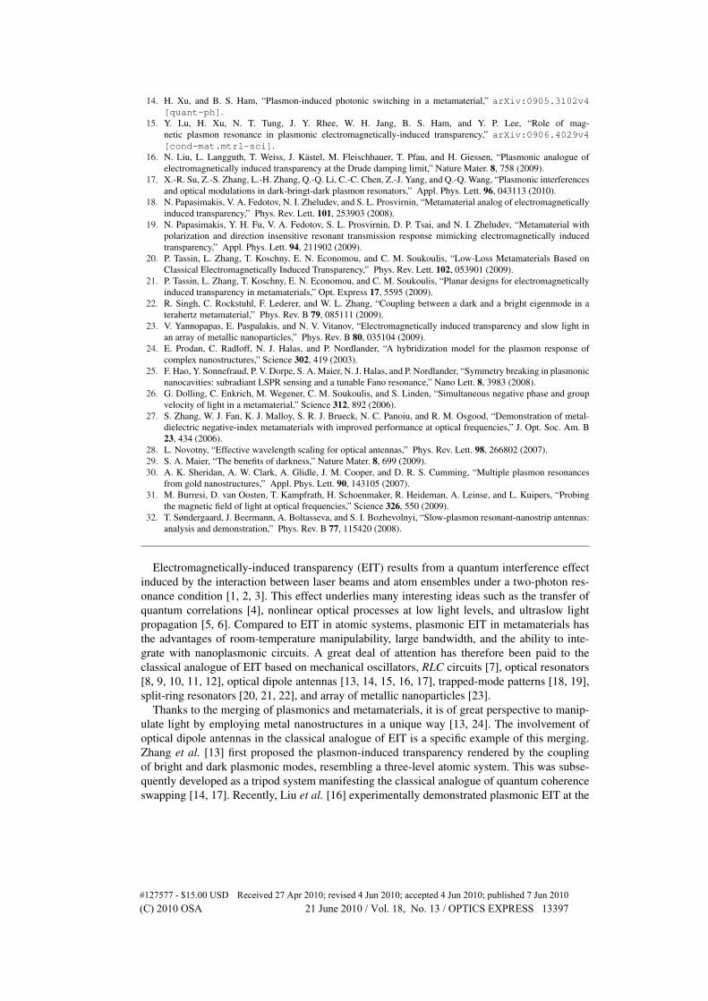
The point of importance is that the quadrupole cannot in general be excited by normal in-cidence because of its vanishing dipole moment (i.e., because it is dark). Thus, in order forthe quadrupole to become activated, highly angled illumination must be employed [13, 29]. Asshown in Fig. 3, two dark modes are magnetically excited at 120 and 240 THz when the planewave irradiates the elongated pair (790 nm) along the -y direction, without broken symmetryin either the incident field or the structure itself. The latter frequency is twice as high as the
#127577 - $15.00 USD Received 27 Apr 2010; revised 4 Jun 2010; accepted 4 Jun 2010; published 7 Jun 2010(C) 2010 OSA 21 June 2010 / Vol. 18, No. 13 / OPTICS EXPRESS 13399
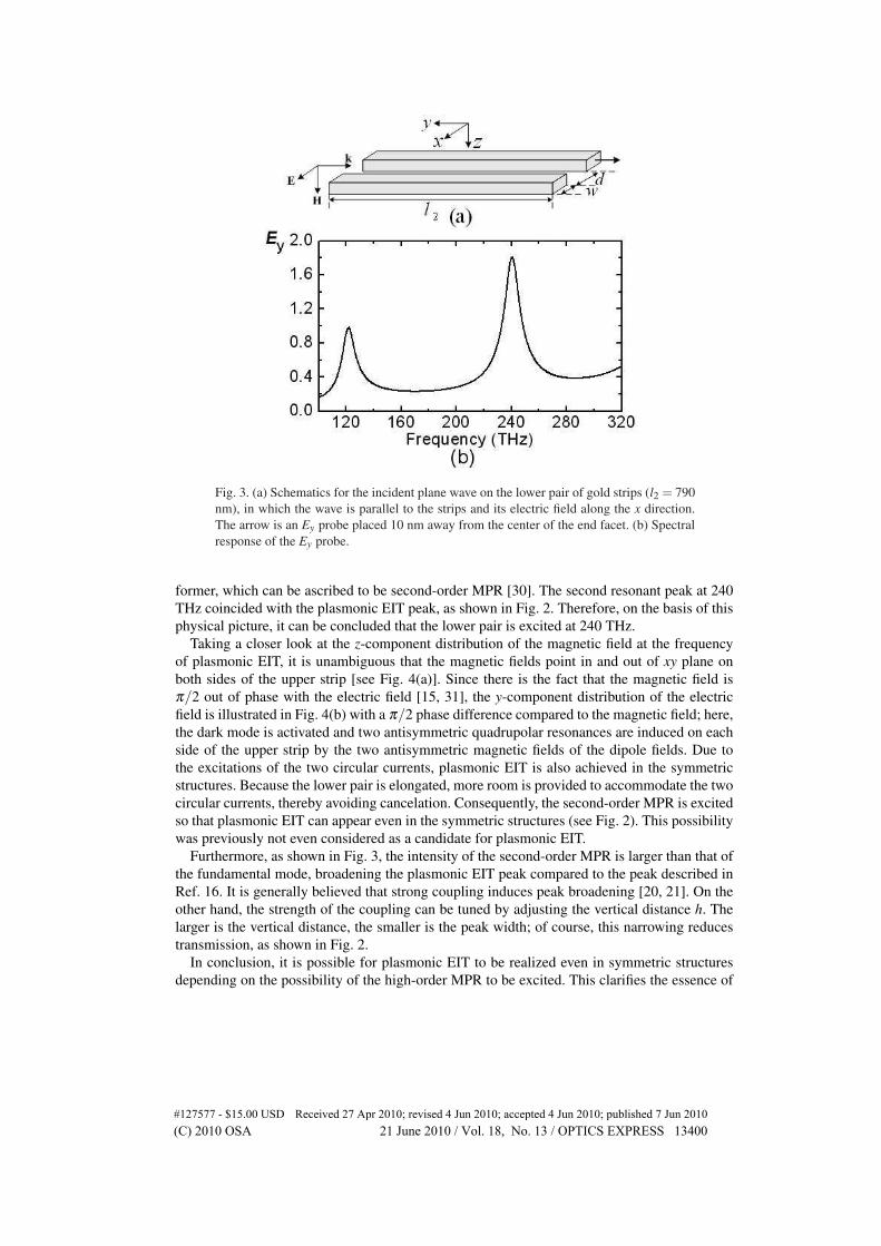
Fig. 3. (a) Schematics for the incident plane wave on the lower pair of gold strips (l2 = 790nm), in which the wave is parallel to the strips and its electric field along the x direction.The arrow is an Ey probe placed 10 nm away from the center of the end facet. (b) Spectralresponse of the Ey probe.
former, which can be ascribed to be second-order MPR [30]. The second resonant peak at 240THz coincided with the plasmonic EIT peak, as shown in Fig. 2. Therefore, on the basis of thisphysical picture, it can be concluded that the lower pair is excited at 240 THz.
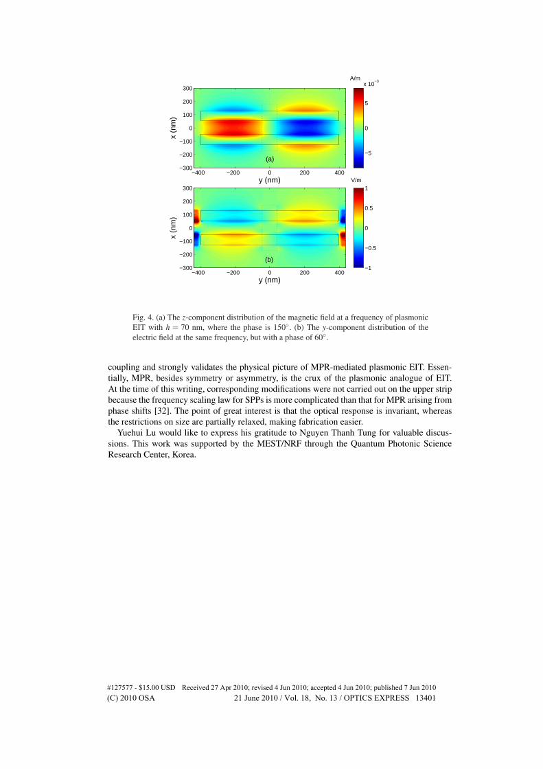
Taking a closer look at the z-component distribution of the magnetic field at the frequencyof plasmonic EIT, it is unambiguous that the magnetic fields point in and out of xy plane onboth sides of the upper strip [see Fig. 4(a)]. Since there is the fact that the magnetic field isπ/2 out of phase with the electric field [15, 31], the y-component distribution of the electricfield is illustrated in Fig. 4(b) with a π/2 phase difference compared to the magnetic field; here,the dark mode is activated and two antisymmetric quadrupolar resonances are induced on eachside of the upper strip by the two antisymmetric magnetic fields of the dipole fields. Due tothe excitations of the two circular currents, plasmonic EIT is also achieved in the symmetricstructures. Because the lower pair is elongated, more room is provided to accommodate the twocircular currents, thereby avoiding cancelation. Consequently, the second-order MPR is excitedso that plasmonic EIT can appear even in the symmetric structures (see Fig. 2). This possibilitywas previously not even considered as a candidate for plasmonic EIT.
Furthermore, as shown in Fig. 3, the intensity of the second-order MPR is larger than that ofthe fundamental mode, broadening the plasmonic EIT peak compared to the peak described inRef. 16. It is generally believed that strong coupling induces peak broadening [20, 21]. On theother hand, the strength of the coupling can be tuned by adjusting the vertical distance h. Thelarger is the vertical distance, the smaller is the peak width; of course, this narrowing reducestransmission, as shown in Fig. 2.
In conclusion, it is possible for plasmonic EIT to be realized even in symmetric structuresdepending on the possibility of the high-order MPR to be excited. This clarifies the essence of
#127577 - $15.00 USD Received 27 Apr 2010; revised 4 Jun 2010; accepted 4 Jun 2010; published 7 Jun 2010(C) 2010 OSA 21 June 2010 / Vol. 18, No. 13 / OPTICS EXPRESS 13400
y (nm)x
(nm
)
−400 −200 0 200 400−300
−200
−100
0
100
200
300
−5
0
5
x 10−3
y (nm)
x (n
m)
−400 −200 0 200 400−300
−200
−100
0
100
200
300
−1
−0.5
0
0.5
1
A/m
V/m
(a)
(b)
Fig. 4. (a) The z-component distribution of the magnetic field at a frequency of plasmonicEIT with h = 70 nm, where the phase is 150◦. (b) The y-component distribution of theelectric field at the same frequency, but with a phase of 60◦.
coupling and strongly validates the physical picture of MPR-mediated plasmonic EIT. Essen-tially, MPR, besides symmetry or asymmetry, is the crux of the plasmonic analogue of EIT.At the time of this writing, corresponding modifications were not carried out on the upper stripbecause the frequency scaling law for SPPs is more complicated than that for MPR arising fromphase shifts [32]. The point of great interest is that the optical response is invariant, whereasthe restrictions on size are partially relaxed, making fabrication easier.
Yuehui Lu would like to express his gratitude to Nguyen Thanh Tung for valuable discus-sions. This work was supported by the MEST/NRF through the Quantum Photonic ScienceResearch Center, Korea.
#127577 - $15.00 USD Received 27 Apr 2010; revised 4 Jun 2010; accepted 4 Jun 2010; published 7 Jun 2010(C) 2010 OSA 21 June 2010 / Vol. 18, No. 13 / OPTICS EXPRESS 13401