plaster in grilles · 2018-03-13 · plaster in grilles ahp plaster-in linear bar grille admp...
TRANSCRIPT
Plaster In GrillesAHP Plaster-in Linear Bar Grille ADMP Plaster-in Linear Diffuser ALSP Plaster-in Linear Slot Diffuser
1/1.5/B/1
TROX UK LtdCaxton WayThetfordNorfolk IP24 3SQ
Telephone +44 (0) 1842 754545Telefax +44 (0) 1842 763051e-mail [email protected]
2
Contents · Description
Description
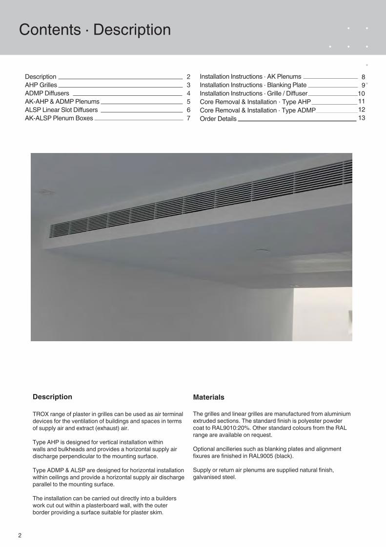
TROX range of plaster in grilles can be used as air terminal devices for the ventilation of buildings and spaces in terms of supply air and extract (exhaust) air.
Type AHP is designed for vertical installation within walls and bulkheads and provides a horizontal supply air discharge perpendicular to the mounting surface.
Type ADMP & ALSP are designed for horizontal installation within ceilings and provide a horizontal supply air discharge parallel to the mounting surface.
The installation can be carried out directly into a builders work cut out within a plasterboard wall, with the outer border providing a surface suitable for plaster skim.
Materials
The grilles and linear grilles are manufactured from aluminium extruded sections. The standard finish is polyester powder coat to RAL9010:20%. Other standard colours from the RAL range are available on request.
Optional ancilleries such as blanking plates and alignment fixures are finished in RAL9005 (black).
Supply or return air plenums are supplied natural finish, galvanised steel.
234567
DescriptionAHP GrillesADMP DiffusersAK-AHP & ADMP Plenums ALSP Linear Slot Diffusers AK-ALSP Plenum Boxes
111213
Installation Instructions · AK Plenums Installation Instructions · Blanking Plate Installation Instructions · Grille / DiffuserCore Removal & Installation · Type AHP Core Removal & Installation · Type ADMP Order Details
89
10
3
AHP Linear Bar Grilles
Type AHP'H
' - 4
/ 'L
' - 4
Construction · Dimensions · Materials
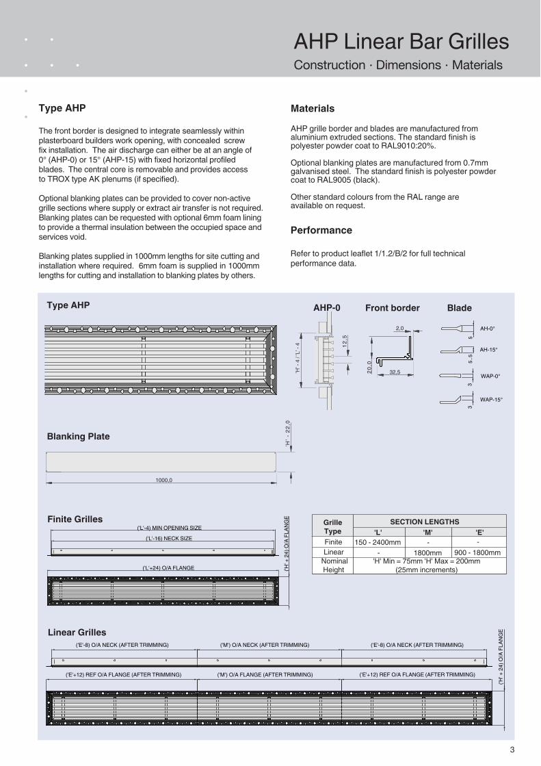
Type AHP
The front border is designed to integrate seamlessly within plasterboard builders work opening, with concealed screw fix installation. The air discharge can either be at an angle of 0° (AHP-0) or 15° (AHP-15) with fixed horizontal profiled blades. The central core is removable and provides access to TROX type AK plenums (if specified).
Optional blanking plates can be provided to cover non-active grille sections where supply or extract air transfer is not required. Blanking plates can be requested with optional 6mm foam lining to provide a thermal insulation between the occupied space and services void.
Blanking plates supplied in 1000mm lengths for site cutting and installation where required. 6mm foam is supplied in 1000mm lengths for cutting and installation to blanking plates by others.
Materials
AHP grille border and blades are manufactured from aluminium extruded sections. The standard finish is polyester powder coat to RAL9010:20%.
Optional blanking plates are manufactured from 0.7mm galvanised steel. The standard finish is polyester powder coat to RAL9005 (black).
Other standard colours from the RAL range are available on request.
AHP-0
12,5
Front border Blade
20,0
32,5
2,0
Blanking Plate
1000,0
'H' -
22,
0
('M') O/A FLANGE (AFTER TRIMMING)('E'+12) REF O/A FLANGE (AFTER TRIMMING)
('H' +
24)
O/A
FLA
NG
E
('E'-8) O/A NECK (AFTER TRIMMING)('M') O/A NECK (AFTER TRIMMING)('E'-8) O/A NECK (AFTER TRIMMING)
('L'-4) MIN OPENING SIZE
('H' +
24)
O/A
FLA
NG
E
('L'+24) O/A FLANGE
('L'-16) NECK SIZE
('E'+12) REF O/A FLANGE (AFTER TRIMMING)
Finite Grilles
Linear Grilles
Performance
Refer to product leaflet 1/1.2/B/2 for full technical performance data.
AH-15°
5.5
3
WAP-0°
WAP-15°
35
AH-0°
SECTION LENGTHSGrille TypeFiniteLinear
Nominal Height
'L' 'M' 'E' 150 - 2400mm
900 - 1800mm1800mm'H' Min = 75mm 'H' Max = 200mm
(25mm increments)
- --
4
ADMP Linear DiffusersConstruction · Dimensions · Materials
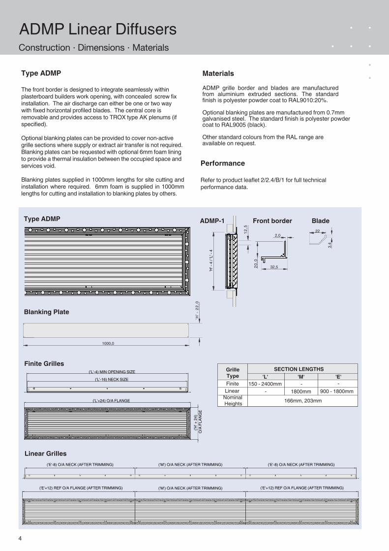
Type ADMP
The front border is designed to integrate seamlessly within plasterboard builders work opening, with concealed screw fix installation. The air discharge can either be one or two way with fixed horizontal profiled blades. The central core is removable and provides access to TROX type AK plenums (if specified).
Optional blanking plates can be provided to cover non-active grille sections where supply or extract air transfer is not required. Blanking plates can be requested with optional 6mm foam lining to provide a thermal insulation between the occupied space and services void.
Blanking plates supplied in 1000mm lengths for site cutting and installation where required. 6mm foam is supplied in 1000mm lengths for cutting and installation to blanking plates by others.
Materials
ADMP grille border and blades are manufactured from aluminium extruded sections. The standard finish is polyester powder coat to RAL9010:20%.
Optional blanking plates are manufactured from 0.7mm galvanised steel. The standard finish is polyester powder coat to RAL9005 (black).
Other standard colours from the RAL range are available on request.
Type ADMP'H
' - 4
/ 'L
' - 4
ADMP-1
12,5
22
3.4
Front border Blade
20,0
32,5
2,0
Blanking Plate
1000,0
'H' -
22,
0
('L'-4) MIN OPENING SIZE
('H
' + 2
4)
O/A
FLA
NG
E
('L'+24) O/A FLANGE
('L'-16) NECK SIZE
Finite Grilles
Linear Grilles
Performance
Refer to product leaflet 2/2.4/B/1 for full technical performance data.
SECTION LENGTHSGrille TypeFinite
LinearNominal Heights
'L' 'M' 'E' 150 - 2400mm
900 - 1800mm1800mm166mm, 203mm
- --
('E'-8) O/A NECK (AFTER TRIMMING)('M') O/A NECK (AFTER TRIMMING)('E'-8) O/A NECK (AFTER TRIMMING)
('M') O/A NECK (AFTER TRIMMING)('E'+12) REF O/A FLANGE (AFTER TRIMMING) ('E'+12) REF O/A FLANGE (AFTER TRIMMING)
5
AK-AHP & ADMP Plenum Boxes
'H' -
5,0
O/A
'D' +
22
270,0 O/A
148,0 I/S
32,0
O/A LENGTH ('L' - 5)
'LN' ACTIVE LENGTH('L' - 35,0)
Construction · Dimensions · Materials
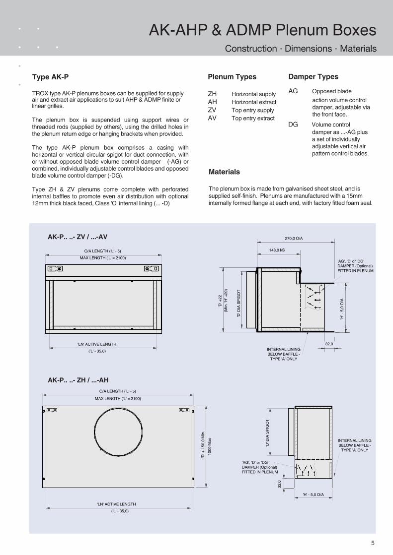
Type AK-P
TROX type AK-P plenums boxes can be supplied for supply air and extract air applications to suit AHP & ADMP finite or linear grilles.
The plenum box is suspended using support wires or threaded rods (supplied by others), using the drilled holes in the plenum return edge or hanging brackets when provided.
The type AK-P plenum box comprises a casing with horizontal or vertical circular spigot for duct connection, with or without opposed blade volume control damper (-AG) or combined, individually adjustable control blades and opposed blade volume control damper (-DG).
Type ZH & ZV plenums come complete with perforated internal baffles to promote even air distribution with optional 12mm thick black faced, Class 'O' internal lining (... -D)
Materials
The plenum box is made from galvanised sheet steel, and is supplied self-finish. Plenums are manufactured with a 15mm internally formed flange at each end, with factory fitted foam seal.
Plenum Types
ZH Horizontal supply AH Horizontal extract ZV Top entry supply AV Top entry extract
Damper Types
AG Opposed blade action volume control damper, adjustable via the front face.
DG Volume control damper as ...-AG plus a set of individually adjustable vertical air pattern control blades.
'H' - 5,0 O/A
32,0
'D' +
150
,0 M
in.
O/A LENGTH ('L' - 5)
'LN' ACTIVE LENGTH('L' - 35,0)
(Min
. 'H' +
20)
INTERNAL LINING BELOW BAFFLE -
TYPE 'A' ONLY
'D' D
IA S
PIG
OT
'D' D
IA S
PIG
OT
AK-P.. ..- ZV / ...-AV
AK-P.. ..- ZH / ...-AH
INTERNAL LINING BELOW BAFFLE -
TYPE 'A' ONLY
MAX LENGTH ('L' = 2100)
MAX LENGTH ('L' = 2100)
1000
Max
'AG', 'D' or 'DG'DAMPER (Optional) FITTED IN PLENUM
'AG', 'D' or 'DG'DAMPER (Optional) FITTED IN PLENUM
6
ALSP Linear Slot DiffusersConstruction · Dimensions · Materials
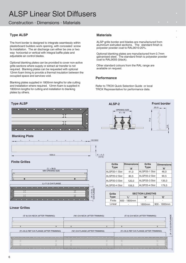
Type ALSP
The front border is designed to integrate seamlessly within plasterboard builders work opening, with concealed screw fix installation. The air discharge can either be one or two way horizontal or vertical with integral baffle plate and adjustable air control blades.
Optional blanking plates can be provided to cover non-active grille sections where supply or extract air transfer is not required. Blanking plates can be requested with optional 12mm foam lining to provide a thermal insulation between the occupied space and services void.
Blanking plates supplied in 1800mm lengths for site cutting and installation where required. 12mm foam is supplied in 1800mm lengths for cutting and installation to blanking plates by others.
Materials
ALSP grille border and blades are manufactured from aluminium extruded sections. The standard finish is polyester powder coat to RAL9010:20%.
Optional blanking plates are manufactured from 0.7mm galvanised steel. The standard finish is polyester powder coat to RAL9005 (black).
Other standard colours from the RAL range are available on request.
Type ALSP
OPENING SIZE
ALSP-2 Front border
Finite Grilles
Linear Grilles
Performance
Refer to TROX Quick Selection Guide or local TROX Representative for performance data.
'A' + 18
25,0
77,0
2,0
('L' + 38,0) MIN OPENING SIZE
('A' +
51,
0)
O/A
FLA
NG
E
(L+71,0) O/A FLANGE
('E'-8) O/A NECK (AFTER TRIMMING)('M') O/A NECK (AFTER TRIMMING)('E'-8) O/A NECK (AFTER TRIMMING)
('M') O/A FLANGE (AFTER TRIMMING)('E'+35,5) REF O/A FLANGE (AFTER TRIMMING)
('A' +
51,
0) O
/A F
LAN
GE
('E'+35,5) REF O/A FLANGE (AFTER TRIMMING)
1800,0 'A' + 4,0 (O/S)
100 MAX=====
Blanking Plate = ==
DimensionsGrille Type
ALSP20-1 SlotALSP20-2 Slot
ALSP20-3 Slot
ALSP20-4 Slot
'A'41,080,5
120,0
159,5
DimensionsGrille Type
ALSP25-1 SlotALSP25-2 Slot
ALSP25-3 Slot
ALSP25-4 Slot
'A'46,090,5
135,0
179,5
SECTION LENGTHSGrille TypeFiniteLinear
'L' 'M' 'E' 600 - 1800mm
900 - 1800mm1800mm- -
-
7
AK-ALSP Plenum BoxesConstruction · Dimensions · Materials
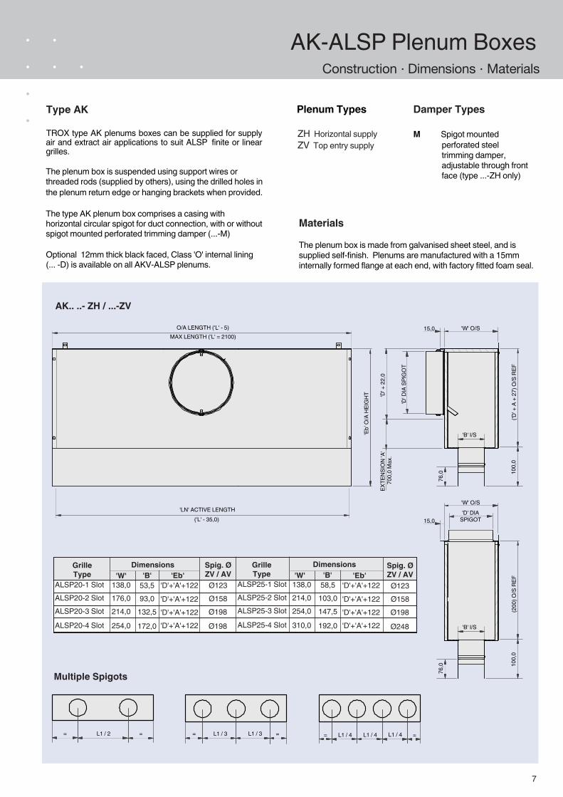
Type AK
TROX type AK plenums boxes can be supplied for supply air and extract air applications to suit ALSP finite or linear grilles.
The plenum box is suspended using support wires or threaded rods (supplied by others), using the drilled holes in the plenum return edge or hanging brackets when provided.
The type AK plenum box comprises a casing with horizontal circular spigot for duct connection, with or without spigot mounted perforated trimming damper (...-M)
Optional 12mm thick black faced, Class 'O' internal lining (... -D) is available on all AKV-ALSP plenums.
Materials
The plenum box is made from galvanised sheet steel, and is supplied self-finish. Plenums are manufactured with a 15mm internally formed flange at each end, with factory fitted foam seal.
Damper Types
M Spigot mounted perforated steel trimming damper, adjustable through front face (type ...-ZH only)
AK.. ..- ZH / ...-ZV
76,0
'B' I/S
100,
0('D
' + A
+ 2
7) O
/S R
EF
15,0 'W' O/S
'D' D
IA S
PIG
OT
'D' +
22,
0EX
TEN
SIO
N 'A
'70
0,0
Max
.
O/A LENGTH ('L' - 5)
'LN' ACTIVE LENGTH('L' - 35,0)
L1 / 2= = L1 / 3= =L1 / 3 L1 / 4= =L1 / 4 L1 / 4
Multiple Spigots
Plenum Types
DimensionsGrille Type
ALSP20-1 SlotALSP20-2 SlotALSP20-3 Slot
ALSP20-4 Slot
'W'138,0176,0214,0
254,0
DimensionsGrille Type
ALSP25-1 SlotALSP25-2 SlotALSP25-3 Slot
ALSP25-4 Slot
'B'53,593,0
132,5
172,0
'W'138,0214,0254,0
310,0
'B'58,5
103,0147,5
192,0
76,0
'B' I/S
100,
0(2
00) O
/S R
EF
15,0
'W' O/S'D' DIA
SPIGOT
Spig. ØZV / AV
Ø123Ø158Ø198
Ø198
Spig. ØZV / AV
Ø123Ø158Ø198
Ø248
ZH Horizontal supply ZV Top entry supply
MAX LENGTH ('L' = 2100)
'Eb'
O/A
HEI
GH
T
'Eb''D'+'A'+122
'D'+'A'+122'D'+'A'+122'D'+'A'+122
'Eb''D'+'A'+122
'D'+'A'+122'D'+'A'+122'D'+'A'+122
8
Installation Instructions
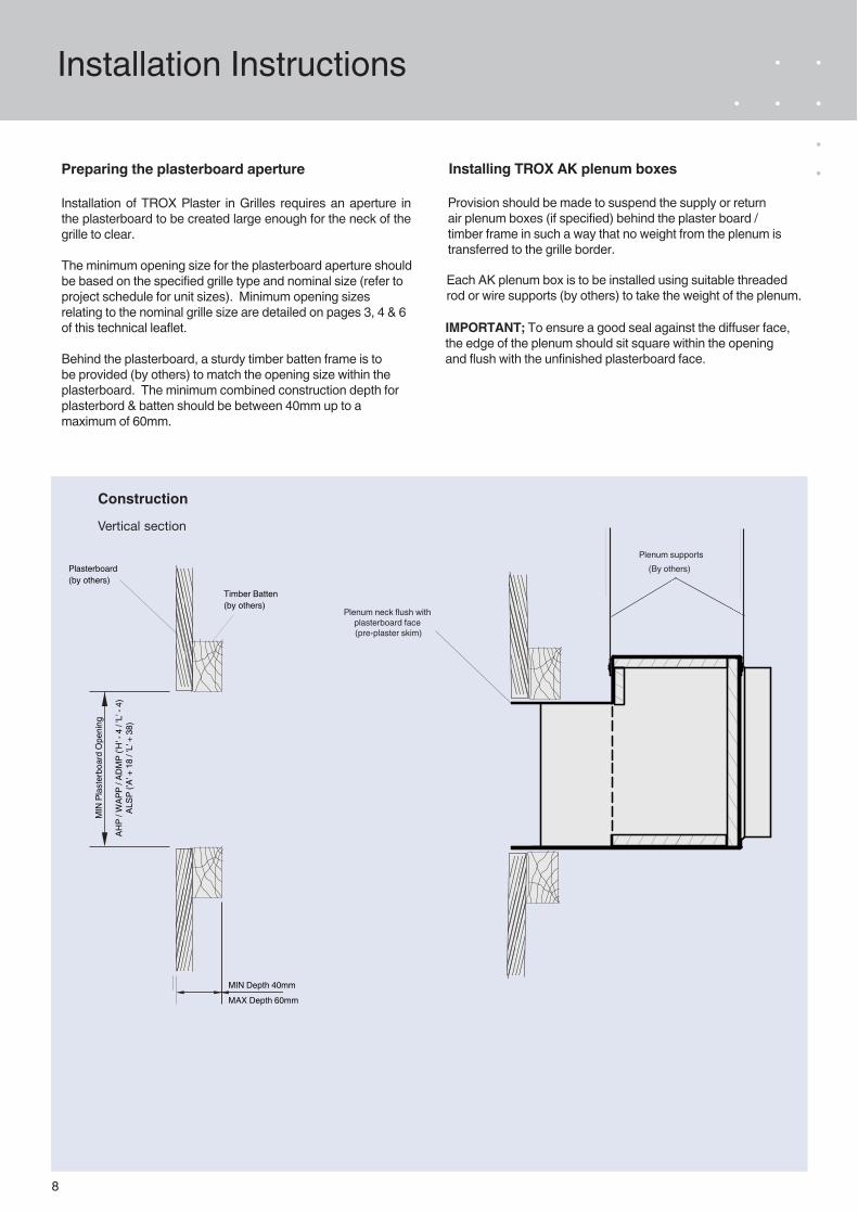
Preparing the plasterboard aperture
Installation of TROX Plaster in Grilles requires an aperture in the plasterboard to be created large enough for the neck of the grille to clear.
The minimum opening size for the plasterboard aperture should be based on the specified grille type and nominal size (refer to project schedule for unit sizes). Minimum opening sizes relating to the nominal grille size are detailed on pages 3, 4 & 6 of this technical leaflet.
Behind the plasterboard, a sturdy timber batten frame is to be provided (by others) to match the opening size within the plasterboard. The minimum combined construction depth for plasterbord & batten should be between 40mm up to a maximum of 60mm.
MIN
Pla
ster
boar
d O
peni
ng
Construction
Vertical section
Plasterboard (by others)
Timber Batten(by others)
MIN Depth 40mmMAX Depth 60mm
Plenum supports(By others)
Plenum neck flush with plasterboard face (pre-plaster skim)
Installing TROX AK plenum boxes
Provision should be made to suspend the supply or return air plenum boxes (if specified) behind the plaster board / timber frame in such a way that no weight from the plenum is transferred to the grille border.
Each AK plenum box is to be installed using suitable threaded rod or wire supports (by others) to take the weight of the plenum.
IMPORTANT; To ensure a good seal against the diffuser face, the edge of the plenum should sit square within the opening and flush with the unfinished plasterboard face.
AHP
/ WAP
P / A
DM
P ('H
' - 4
/ 'L
' - 4
)
ALSP
('A'
+ 1
8 / 'L
' + 3
8)
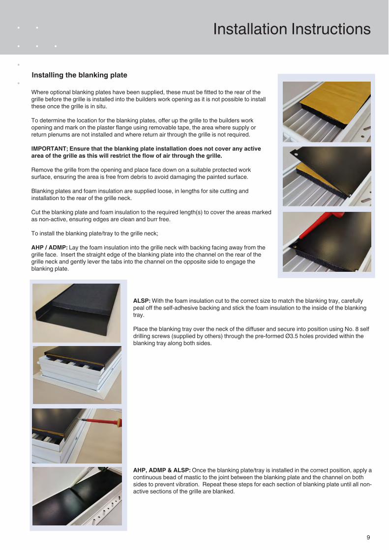
Where optional blanking plates have been supplied, these must be fitted to the rear of the grille before the grille is installed into the builders work opening as it is not possible to install these once the grille is in situ.
To determine the location for the blanking plates, offer up the grille to the builders work opening and mark on the plaster flange using removable tape, the area where supply or return plenums are not installed and where return air through the grille is not required.
IMPORTANT; Ensure that the blanking plate installation does not cover any active area of the grille as this will restrict the flow of air through the grille.
Remove the grille from the opening and place face down on a suitable protected work surface, ensuring the area is free from debris to avoid damaging the painted surface.
Blanking plates and foam insulation are supplied loose, in lengths for site cutting and installation to the rear of the grille neck.
Cut the blanking plate and foam insulation to the required length(s) to cover the areas marked as non-active, ensuring edges are clean and burr free.
To install the blanking plate/tray to the grille neck;
AHP / ADMP: Lay the foam insulation into the grille neck with backing facing away from the grille face. Insert the straight edge of the blanking plate into the channel on the rear of the grille neck and gently lever the tabs into the channel on the opposite side to engage the blanking plate.
9
Installation Instructions
Installing the blanking plate
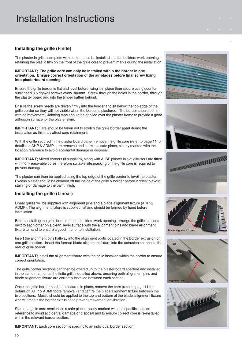
ALSP: With the foam insulation cut to the correct size to match the blanking tray, carefully peal off the self-adhesive backing and stick the foam insulation to the inside of the blanking tray.
Place the blanking tray over the neck of the diffuser and secure into position using No. 8 self drilling screws (supplied by others) through the pre-formed Ø3.5 holes provided within the blanking tray along both sides.
AHP, ADMP & ALSP: Once the blanking plate/tray is installed in the correct position, apply a continuous bead of mastic to the joint between the blanking plate and the channel on both sides to prevent vibration. Repeat these steps for each section of blanking plate until all non-active sections of the grille are blanked.
10
Installation Instructions
Installing the grille (Finite)
The plaster in grille, complete with core, should be installed into the builders work opening, retaining the plastic film on the front of the grille core to prevent marks during the installation.
IMPORTANT; The grille core can only be installed within the border in one orientation. Ensure correct orientation of the air blades before final screw fixing into plasterboard opening.
Ensure the grille border is flat and level before fixing it in place then secure using counter sunk head 3.5 drywall screws every 300mm. Screw through the holes in the border, through the plaster board and into the timber batten behind.
Ensure the screw heads are driven firmly into the border and sit below the top edge of the grille border so they will not visible when the border is plastered. The border should be firm with no movement. Jointing tape should be applied over the plaster frame to provide a good adhesion surface for the plaster skim.
IMPORTANT; Care should be taken not to stretch the grille border apart during the installation as this may affect core retainment.
With the grille secured in the plaster board panel, remove the grille core (refer to page 11 for details on AHP & ADMP core removal) and store in a safe place, clearly marked with the location reference to avoid accidental damage or disposal.
IMPORTANT; Mitred corners (if supplied), along with ALSP plaster in slot diffusers are fitted with non-removable cores therefore suitable site masking of the grille core is required to prevent damage.
The plaster can then be applied using the top edge of the grille border to level the plaster. Excess plaster should be cleaned off the inside of the grille & border before it dries to avoid staining or damage to the paint finish.
Installing the grille (Linear)
Linear grilles will be supplied with alignment pins and a blade alignment fixture (AHP & ADMP). The alignment fixture is supplied flat and should be formed by hand before installation.
Before installing the grille border into the builders work opening, arrange the grille sections next to each other on a clean, level surface with the alignment pins and blade allignment fixture to hand to ensure a good fit prior to installation.
Insert the alignment pins halfway into the alignment ports located in the border extrusion on one grille section. Insert the formed blade allignment fixture into the extrusion channel at the rear of grille border.
IMPORTANT; Install the allignment fixture with the grille installed within the border to ensure correct orientation.
The grille border sections can then be offered up to the plaster board aperture and installed in the same manner as the finite grilles detailed above, ensuring both allignment pins and blade allignment fixture are correctly installed between each section.
Once the grille border has been secured in place, remove the core (refer to page 11 for details on AHP & ADMP core removal) and centre the blade alignment fixture between the two sections. Mastic should be applied to the top and bottom of the blade allignment fixture where it meets the border extrusion to prevent movement or vibration.
Store the grille core sections in a safe place, clearly marked with the specific location reference to avoid accidental damage or disposal and to ensure correct core is re-installed within the relevant border section.
IMPORTANT; Each core section is specific to an individual border section.
Alignment pin
Blade alignment fixture
11
Installation Instructions
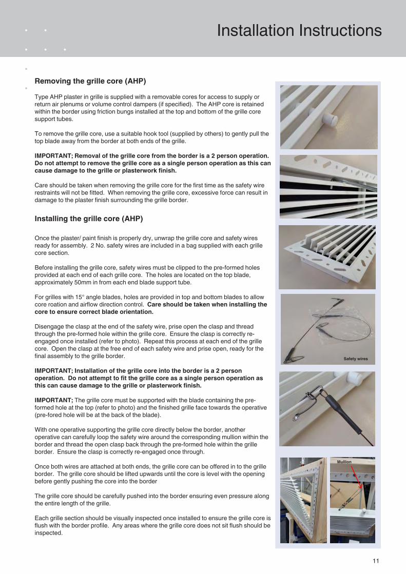
Installing the grille core (AHP)
Once the plaster/ paint finish is properly dry, unwrap the grille core and safety wires ready for assembly. 2 No. safety wires are included in a bag supplied with each grille core section.
Before installing the grille core, safety wires must be clipped to the pre-formed holes provided at each end of each grille core. The holes are located on the top blade, approximately 50mm in from each end blade support tube.
For grilles with 15° angle blades, holes are provided in top and bottom blades to allow core roation and airflow direction control. Care should be taken when installing the core to ensure correct blade orientation.
Disengage the clasp at the end of the safety wire, prise open the clasp and thread through the pre-formed hole within the grille core. Ensure the clasp is correctly re-engaged once installed (refer to photo). Repeat this process at each end of the grille core. Open the clasp at the free end of each safety wire and prise open, ready for the final assembly to the grille border.
IMPORTANT; Installation of the grille core into the border is a 2 person operation. Do not attempt to fit the grille core as a single person operation as this can cause damage to the grille or plasterwork finish.
IMPORTANT; The grille core must be supported with the blade containing the pre-formed hole at the top (refer to photo) and the finished grille face towards the operative (pre-fored hole will be at the back of the blade).
With one operative supporting the grille core directly below the border, another operative can carefully loop the safety wire around the corresponding mullion within the border and thread the open clasp back through the pre-formed hole within the grille border. Ensure the clasp is correctly re-engaged once through.
Once both wires are attached at both ends, the grille core can be offered in to the grille border. The grille core should be lifted upwards until the core is level with the opening before gently pushing the core into the border
The grille core should be carefully pushed into the border ensuring even pressure along the entire length of the grille.
Each grille section should be visually inspected once installed to ensure the grille core is flush with the border profile. Any areas where the grille core does not sit flush should be inspected.
Removing the grille core (AHP)
Type AHP plaster in grille is supplied with a removable cores for access to supply or return air plenums or volume control dampers (if specified). The AHP core is retained within the border using friction bungs installed at the top and bottom of the grille core support tubes.
To remove the grille core, use a suitable hook tool (supplied by others) to gently pull the top blade away from the border at both ends of the grille.
IMPORTANT; Removal of the grille core from the border is a 2 person operation. Do not attempt to remove the grille core as a single person operation as this can cause damage to the grille or plasterwork finish.
Care should be taken when removing the grille core for the first time as the safety wire restraints will not be fitted. When removing the grille core, excessive force can result in damage to the plaster finish surrounding the grille border.
Safety wires
Mullion
12
Installation Instructions
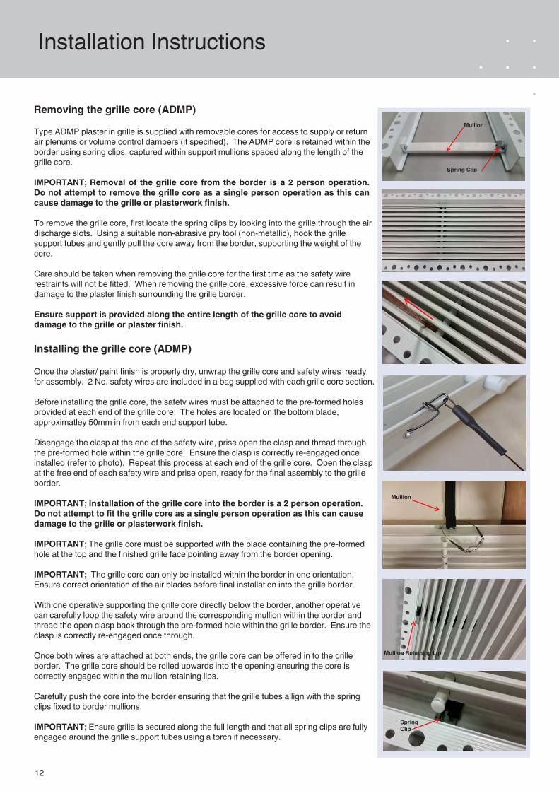
Removing the grille core (ADMP)
Type ADMP plaster in grille is supplied with removable cores for access to supply or return air plenums or volume control dampers (if specified). The ADMP core is retained within the border using spring clips, captured within support mullions spaced along the length of the grille core.
IMPORTANT; Removal of the grille core from the border is a 2 person operation. Do not attempt to remove the grille core as a single person operation as this can cause damage to the grille or plasterwork finish.
To remove the grille core, first locate the spring clips by looking into the grille through the air discharge slots. Using a suitable non-abrasive pry tool (non-metallic), hook the grille support tubes and gently pull the core away from the border, supporting the weight of the core.
Care should be taken when removing the grille core for the first time as the safety wire restraints will not be fitted. When removing the grille core, excessive force can result in damage to the plaster finish surrounding the grille border.
Ensure support is provided along the entire length of the grille core to avoid damage to the grille or plaster finish.
Installing the grille core (ADMP)
Once the plaster/ paint finish is properly dry, unwrap the grille core and safety wires ready for assembly. 2 No. safety wires are included in a bag supplied with each grille core section.
Before installing the grille core, the safety wires must be attached to the pre-formed holes provided at each end of the grille core. The holes are located on the bottom blade, approximatley 50mm in from each end support tube.
Disengage the clasp at the end of the safety wire, prise open the clasp and thread through the pre-formed hole within the grille core. Ensure the clasp is correctly re-engaged once installed (refer to photo). Repeat this process at each end of the grille core. Open the clasp at the free end of each safety wire and prise open, ready for the final assembly to the grille border.
IMPORTANT; Installation of the grille core into the border is a 2 person operation. Do not attempt to fit the grille core as a single person operation as this can cause damage to the grille or plasterwork finish.
IMPORTANT; The grille core must be supported with the blade containing the pre-formed hole at the top and the finished grille face pointing away from the border opening.
IMPORTANT; The grille core can only be installed within the border in one orientation. Ensure correct orientation of the air blades before final installation into the grille border.
With one operative supporting the grille core directly below the border, another operative can carefully loop the safety wire around the corresponding mullion within the border and thread the open clasp back through the pre-formed hole within the grille border. Ensure the clasp is correctly re-engaged once through.
Once both wires are attached at both ends, the grille core can be offered in to the grille border. The grille core should be rolled upwards into the opening ensuring the core is correctly engaged within the mullion retaining lips.
Carefully push the core into the border ensuring that the grille tubes allign with the spring clips fixed to border mullions.
IMPORTANT; Ensure grille is secured along the full length and that all spring clips are fully engaged around the grille support tubes using a torch if necessary.
Mullion
Mullion Retaining Lip
Spring Clip
Mullion
Spring Clip
13
Order Details
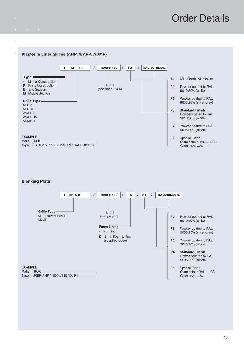
AHP-0AHP-15WAPP-0WAPP-15ADMP-1
A1 Mill Finish Aluminium
P0 Powder coated to RAL 9010:50% (white)
P2 Powder coated to RAL 9006:25% (silver grey)
P3 Standard Finish Powder coated to RAL 9010:20% (white)
P4 Powder coated to RAL 9005:20% (black)
P6 Special Finish State colour RAL..., BS... Gloss level ...%
L x H(see page 3 & 4)
TEEEEEEEEEEEEEEEEEEEEEEEEEEEEEEEEEEEEEEEZEEEEEEEEEEEEEEEEEEEEEEEEEEEEEEEEEEEEEEEU
Plaster In Liner Grilles (AHP, WAPP, ADMP)
F - AHP-15 / 1500 x 150 / P3 / RAL 9010:20%
EXAMPLEMake: TROXType: F-AHP-15 / 1500 x 150 / P3 / RAL9010:20%
Grille Type
Type - Linear ConstructionF Finite ConstructionE End SectionM Middle Section
P0 Powder coated to RAL 9010:50% (white)
P2 Powder coated to RAL 9006:25% (silver grey)
P6 Special Finish State colour RAL..., BS... Gloss level ...%
L x H(see page 3)
TEEEEEEEEEEEEEEEEEEEEEEEEEEEEEEEEEEEEEEEZEEEEEEEEEEEEEEEEEEEEEEEEEEEEEEEEEEEEEEEU
Blanking Plate
UKBP-AHP
EXAMPLEMake: TROXType: UKBP-AHP / 1000 x 150 / D / P4
/ 1000 x 150 / D / P4 / RAL9005:20%
P3 Powder coated to RAL 9010:20% (white)
P4 Standard Finish Powder coated to RAL 9005:20% (black)
- Not LinedD 12mm Foam Lining (supplied loose)
Foam Lining
AHP (covers WAPP)ADMP
Grille Type
14
Order Details
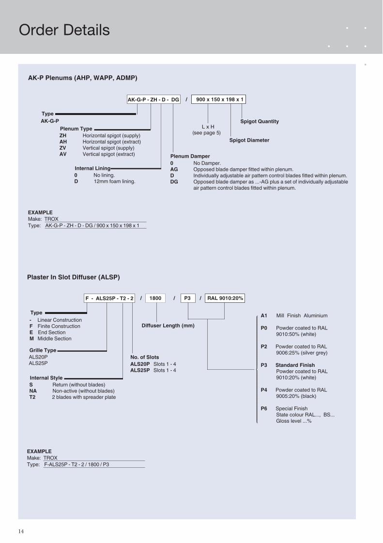
ZH Horizontal spigot (supply)AH Horizontal spigot (extract)ZV Vertical spigot (supply)AV Vertical spigot (extract)
L x H(see page 5)
AK-P Plenums (AHP, WAPP, ADMP)
AK-G-P - ZH - D - DG / 900 x 150 x 198 x 1
EXAMPLEMake: TROXType: AK-G-P - ZH - D - DG / 900 x 150 x 198 x 1
Plenum Type
Type AK-G-P
0 No lining.D 12mm foam lining.
Internal Lining0 No Damper.AG D DG
Opposed blade damper fitted within plenum.Individually adjustable air pattern control blades fitted within plenum. Opposed blade damper as ...-AG plus a set of individually adjustable air pattern control blades fitted within plenum.
Plenum Damper
Spigot Diameter
Spigot Quantity
ALS20PALS25P
A1 Mill Finish Aluminium
P0 Powder coated to RAL 9010:50% (white)
P2 Powder coated to RAL 9006:25% (silver grey)
P3 Standard Finish Powder coated to RAL 9010:20% (white)
P4 Powder coated to RAL 9005:20% (black)
P6 Special Finish State colour RAL..., BS... Gloss level ...%
Diffuser Length (mm)
TEEEEEEEEEEEEEEEEEEEEEEEEEEEEEEEEEEEEEEEZEEEEEEEEEEEEEEEEEEEEEEEEEEEEEEEEEEEEEEEU
Plaster In Slot Diffuser (ALSP)
F - ALS25P - T2 - 2 / 1800 / P3 / RAL 9010:20%
EXAMPLEMake: TROXType: F-ALS25P - T2 - 2 / 1800 / P3
Grille Type
Type - Linear ConstructionF Finite ConstructionE End SectionM Middle Section
EXAMPLEMake: TROXType: UKBP-AHP / 1150 x 150 / D / P4
S Return (without blades)NA Non-active (without blades)T2 2 blades with spreader plate
Internal Style
ALS20P Slots 1 - 4 ALS25P Slots 1 - 4
No. of Slots
15
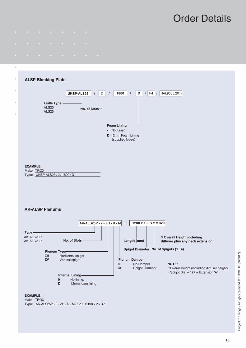
ALSP Blanking Plate
UKBP-ALS25
EXAMPLEMake: TROXType: UKBP-ALS25 / 2 / 1800 / D
/ 2 / 1800 / D / P4 / RAL9005:20%
- Not LinedD 12mm Foam Lining (supplied loose)
Foam Lining
No. of Slots
ZH ZV
Horizontal spigot Vertical spigot
Length (mm)
AK-ALSP Plenums
AK-ALS25P - 2 - ZH - D - M / 1200 x 198 x 2 x 320
EXAMPLEMake: TROXType: AK-ALS25P - 2 - ZH - D - M / 1200 x 198 x 2 x 320
Plenum Type
Type AK-ALS20PAK-ALS25P
0 No lining.D 12mm foam lining.
Internal Lining
0 No Damper.M Spigot Damper.
Plenum Damper
Spigot Diameter
1) Overall Height includingNo. of Slots diffuser plus any neck extension
No. of Spigots (1...4)
NOTE:1) Overall height (including diffuser height) = Spigot Dia. + 127 + Extension 'A'
Subj
ect t
o ch
ange
· Al
l rig
hts
rese
rved
© T
ROX
UK (0
6/20
17)
Order Details
ALS20ALS25
Grille Type