plate and box girder stiffener design in view …eeme.ntua.gr/proceedings/6th/3b_1.pdf · 286 plate...
TRANSCRIPT

286
PLATE AND BOX GIRDER STIFFENER DESIGN IN VIEW OF EU ROCODE 3 PART 1.5
Darko Beg Professor
University of Ljubljana, Faculty of Civil and Geodetic Engineering Ljubljana, Slovenia
Email: [email protected] 1. ABSTRACT In this paper two important issues related to stability problems of stiffeners in plate and box girders are discussed: torsional stability of open stiffeners and stability of transverse stiffeners. Both problems are closely related to the new Eurocode standard EN 1993-1-5 on stability of plated structures giving answers to some open questions not solved completely in the mentioned standard. Generally, transverse stiffeners are subjected to different loadings that tend to destabilize a stiffener. Most typical are deviation forces from longitudinal compression in the web, axial forces in the stiffener due to tension field action caused by shear forces in the web and axial forces in the stiffener from direct external loading acting on the stiffener as in the case of bearing stiffeners. Additionally to EN 1993-1-5 design rules a simplified design procedure for transverse stiffeners is proposed that includes second order effects and all relevant loadings. Based on extensive FEM simulations, criteria for preventing undesirable torsional instability of open stiffeners are also given taking into account beneficial effects of the bending stiffness of the plating and unfavourable effects of compression forces in the plating. 2. INTRODUCTION Transverse stiffeners of plate girders are usually designed as rigid stiffeners to provide adequate shear resistance and supports for longitudinal stiffeners. Traditionally the design of rigid stiffeners is based on the stiffness criterion – minimum required stiffness for the ideal elastic case increased to take account of initial imperfections, residual stresses and post-buckling behaviour of the panels between stiffeners. The other possibility, adopted in EN 1993-1-5 [1], is to design transverse stiffeners explicitly for strength and deformability and to consider all relevant loads acting on the stiffener, initial imperfections and second order effects. This approach is a bit more complex than the first one, but may lead to more accurate and more economical design of stiffeners.

287
Longitudinal stiffeners are dealt with only related to their torsional stability resistance that should be adequate to prevent premature buckling of the stiffeners and of the stiffened panel. Generally, the resistance of longitudinal stiffeners is incorporated in the resistance of longitudinally stiffened panels and the paper does not address this topic. More details on the stiffener design can be found in the commentary to the EN 1993-1-5 [2], prepared by the members of the project team that drafted the standard (the document is available free of charge on the following web page: eurocodes.jrc.it). For more reading see also [3] and [4]. 3. TRANSVERSE STIFFENERS 3.1 MINIMUM REQUIREMENTS FOR TRANSVERSE STIFFENERS According to EN 1993-1-5 transverse stiffeners should preferably provide rigid support for a plate with or without longitudinal stiffeners. They should be able to carry deviation forces from the adjacent compressed panels and be designed both for appropriate strength and stiffness. In principle, based on the second order elastic analysis, the following criteria should be satisfied: - maximum stress in the stiffener under design load should not exceed fy/γM1 - additional deflection should not exceed b/300
ymax
M1
f b, w
300σ ≤ ≤
γ (1)
where b is the plate width (see Fig. 1), fy is yield stress of the stiffener and γM1 is partial resistance factor for the stability case.
A
A
w0
1
2
EdN
NEd
adjacent transverse stiffenersstiffenerto be checked
A-A
NEd NEd
a a1 2
0w
B-B
w = min0
b300 300
a300a1 2, ,
B
B
ba
a
Fig. 1: Static scheme for transverse stiffener Any other relevant load acting on the stiffener (axial force in the stiffener – e.g. due to directly applied external force – or possible horizontal transverse loading on the stiffener –
288
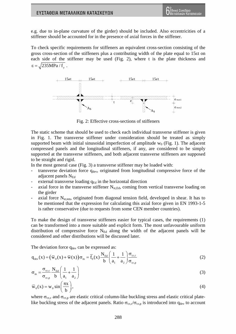
e.g. due to in-plane curvature of the girder) should be included. Also eccentricities of a stiffener should be accounted for in the presence of axial forces in the stiffener. To check specific requirements for stiffeners an equivalent cross-section consisting of the gross cross-section of the stiffeners plus a contributing width of the plate equal to 15εt on each side of the stiffener may be used (Fig. 2), where t is the plate thickness and
y235MPa / fε = .
sAsA
t
15 t 15 t 15 t15 t
e e
e
max1
max2
Fig. 2: Effective cross-sections of stiffeners The static scheme that should be used to check each individual transverse stiffener is given in Fig. 1. The transverse stiffener under consideration should be treated as simply supported beam with initial sinusoidal imperfection of amplitude w0 (Fig. 1). The adjacent compressed panels and the longitudinal stiffeners, if any, are considered to be simply supported at the transverse stiffeners, and both adjacent transverse stiffeners are supposed to be straight and rigid. In the most general case (Fig. 3) a transverse stiffener may be loaded with: - transverse deviation force qdev, originated from longitudinal compressive force of the
adjacent panels NEd - external transverse loading qEd in the horizontal direction - axial force in the transverse stiffener Nst,Ed, coming from vertical transverse loading on
the girder - axial force Nst,ten, originated from diagonal tension field, developed in shear. It has to
be mentioned that the expression for calculating this axial force given in EN 1993-1-5 is rather conservative (due to requests from some CEN member countries).
To make the design of transverse stiffeners easier for typical cases, the requirements (1) can be transformed into a more suitable and explicit form. The most unfavourable uniform distribution of compressive force NEd along the width of the adjacent panels will be considered and other distributions will be discussed later. The deviation force qdev can be expressed as:
( ) cr,cEddev 0 m 0
1 2 cr,p
N 1 1q (x) w (x) w(x) f (x)
b a a
σ = + σ = +
σ (2)
cr,c Edm
cr,p 1 2
N 1 1
b a a
σ σ = +
σ (3)
0 0
xw (x) w sin
b
π =
, (4)
where σcr,c and σcr,p are elastic critical column-like buckling stress and elastic critical plate-like buckling stress of the adjacent panels. Ratio σcr,c/σcr,p is introduced into qdev to account
289
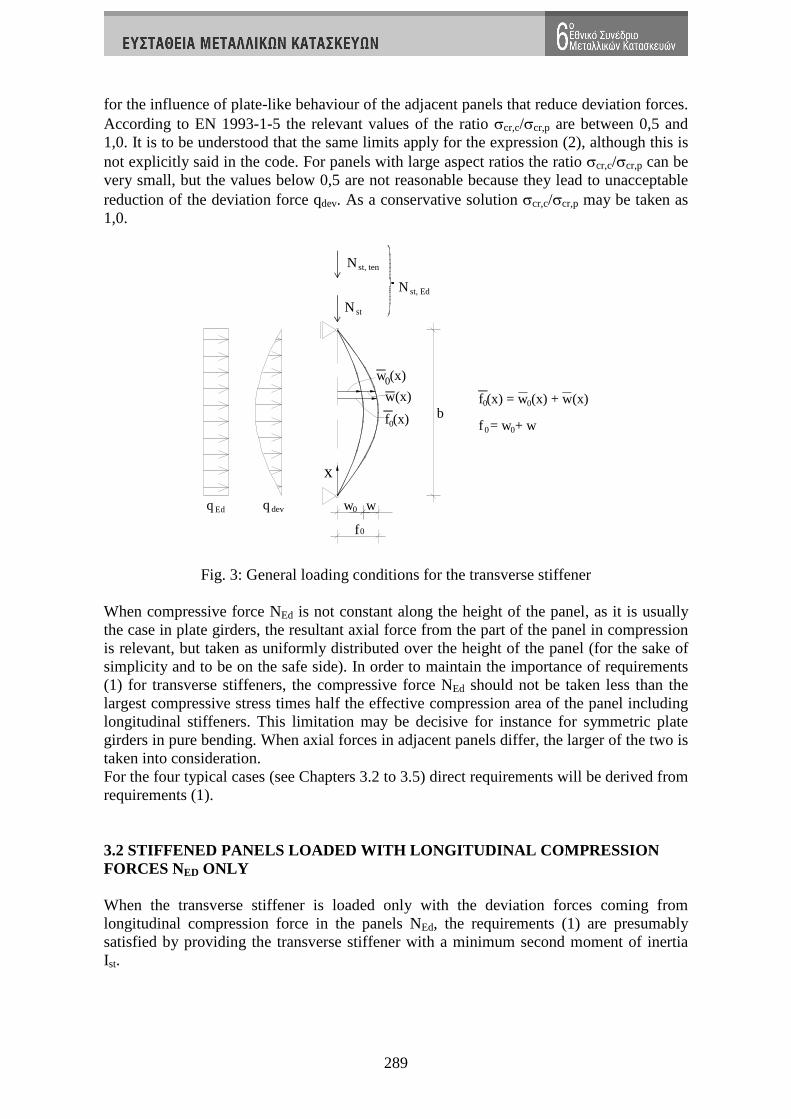
for the influence of plate-like behaviour of the adjacent panels that reduce deviation forces. According to EN 1993-1-5 the relevant values of the ratio σcr,c/σcr,p are between 0,5 and 1,0. It is to be understood that the same limits apply for the expression (2), although this is not explicitly said in the code. For panels with large aspect ratios the ratio σcr,c/σcr,p can be very small, but the values below 0,5 are not reasonable because they lead to unacceptable reduction of the deviation force qdev. As a conservative solution σcr,c/σcr,p may be taken as 1,0.
Nst, ten
N st
Edq w0devq w
f 0
w (x)0
w(x)
f (x)0b
f (x) = w (x) + w(x)0 0
f = w + w0 0
x
N st, Ed
Fig. 3: General loading conditions for the transverse stiffener When compressive force NEd is not constant along the height of the panel, as it is usually the case in plate girders, the resultant axial force from the part of the panel in compression is relevant, but taken as uniformly distributed over the height of the panel (for the sake of simplicity and to be on the safe side). In order to maintain the importance of requirements (1) for transverse stiffeners, the compressive force NEd should not be taken less than the largest compressive stress times half the effective compression area of the panel including longitudinal stiffeners. This limitation may be decisive for instance for symmetric plate girders in pure bending. When axial forces in adjacent panels differ, the larger of the two is taken into consideration. For the four typical cases (see Chapters 3.2 to 3.5) direct requirements will be derived from requirements (1). 3.2 STIFFENED PANELS LOADED WITH LONGITUDINAL COMPR ESSION FORCES NED ONLY When the transverse stiffener is loaded only with the deviation forces coming from longitudinal compression force in the panels NEd, the requirements (1) are presumably satisfied by providing the transverse stiffener with a minimum second moment of inertia Ist.
290
With NEd uniformly distributed over the width of the panel and 0w (x) taken as sine
function from Eq. (2), both the additional deflection w(x)and the deviation force qdev(x)
have also a sinusoidal shape. By taking this into consideration, maximum stress σmax and maximum additional deflection w can be calculated as:
2 2dev,0 maxmax max 0 m max
max 2 2st st st
q b eM e (w w) b e
I I I
+ σσ = = =
π π
(5)
4 4 2dev,0 0 m max4 4 2
st st max
q b (w w) b bw
EI EI Ee
+ σ σ= = =
π π π
(6)
where Mmax is maximum value of the bending moment in the stiffener caused by the deviation
force emax is the distance from the extreme fibre of the stiffener to the centroid of the stiffener
(see Fig. 2) qdev,0 =(wo+w)σm is the amplitude of the deviation force qdev(x). By introducing (6) into (5) a relation between Ist and σm can be determined:
4 2maxm
st 0 2max
EebI 1 w
E b
πσ = +
π σ (7)
or, with due account taken of (6), Ist can be expressed in terms of w 4
0mst
wbI 1
E w
σ = +
π . (8)
To get minimum allowable values for Ist, maximum allowable values of σmax=fy/γM1 and w=b/300 are introduced in (7) and (8), respectively. Because of (6) expressions (7) and (8) can be then merged in one condition given in EN 1993-1-5:
4
mst 0
b 300I 1 w u
E b
σ ≥ +
π (9)
2max M1
y
Eeu 1.
b300f
π γ= ≥ (10)
When u is less than 1,0, a displacement check is decisive and u is taken as 1,0 in (9), otherwise a strength check is in force. 3.3 STIFFENED PANELS LOADED WITH LONGITUDINAL COMPR ESSION FORCES NED AND AXIAL FORCES IN THE DOUBLE SIDED TRANSVERSE STIFFENER NST,ED (NST AND/OR NST,TEN) When in addition to the deviation forces the double sided transverse stiffener is loaded with an external axial force, then the deviation force is transformed into an additional axial force ∆Nst,Ed in the stiffener:
2m
st,Ed 2
bN
σ∆ =
π. (11)
The mechanical model is for this case shown in Fig. 3 (excluding qEd). The stiffener is loaded with a deviation force from longitudinal compression in the panels (NEd) and axial
291
force Nst,Ed in the stiffener, resulting from the tension field action (Nst,ten) and/or from the external loading (Nst). Equilibrium differential equation of the stiffener can be written as:
st xxxx st ,Ed 0 xx xx dev m 0EI w, N (w , w, ) q (x) (w w)+ + = = σ + (12)
or
st ,Ed2 2 2 2 2 2 mxxxx xx 0 0 xx
st st
Nw, w, w w w , , ,
EI EI
σ+ω −α = α −ω ω = α = (13)
Sine function x
w w sinb
π
= (14)
automatically fulfils all static and kinematic boundary conditions and can be taken as a suitable solution of (13). A free constant w is easily obtained from (13):
22 2
2
o o4 22 2
4 2
bw w Kw
b b
πω +α
= =
π π−ω −α
(15)
Constant K can be rewritten as follows: 2
42
4
K
b
β=π
−β
(16)
where 22
2 mst,Ed st,Ed st,Ed2 2
st
b(N N ) and N
EI b
σπβ = + ∆ ∆ =
π (17)
By introducing
st,Ed st,Ed st,EdN N NΣ = + ∆ (18)
and the Euler buckling strength of a stiffener 2
stcr,st 2
EIN
b
π
= (19)
the amplitudes of the additional deflection w and total deflection f are:
ocr,st
st ,Ed
1w w
N1
N
=
−Σ
(20)
o ost ,Ed
cr,st
1f w w w
N1
N
= + =Σ
−. (21)
Comparing (20) and (21) to the standard solution for the compressed imperfect bar, it is evident that the deviation force qdev coming from longitudinal compression in the web panels (NEd) can be replaced by the additional axial force ∆Nst,Ed=σmb2/π2 in the stiffener. ∆Nst,Ed is a small fraction of a longitudinal compression force NEd in the plate panels. This solution is very simple and easy to apply. When the distribution of the longitudinal compression stresses is not constant (i.e. web panel of a girder under bending moment), the results are on the safe side.
292
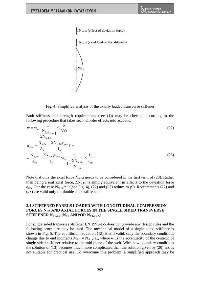
N (axial load on the stiffener)st, Ed
st, EdN (effect of deviation force)
w0
Fig. 4: Simplified analysis of the axially loaded transverse stiffener Both stiffness and strength requirements (see (1)) may be checked according to the following procedure that takes second order effects into account:
ocr,st
st,Ed
1 bw w
N 3001
N
= ≤−
Σ
(22)
st,Ed st ,Ed maxmax
st st
yst ,Ed st ,Ed maxo
st ,Edst st M1
cr,st
N N ef
A I
fN N e 1w
NA I1
N
Σσ = + =
Σ= + ≤
Σ γ−
(23)
Note that only the axial force Nst,Ed needs to be considered in the first term of (23). Rather than being a real axial force, ∆Nst,Ed is simply equivalent in effects to the deviation force qdev. For the case Nst,Ed = 0 (see Fig. 4), (22) and (23) reduce to (9). Requirements (22) and (23) are valid only for double sided stiffeners. 3.4 STIFFENED PANELS LOADED WITH LONGITUDINAL COMPR ESSION FORCES NED AND AXIAL FORCES IN THE SINGLE SIDED TRANSVERSE STIFFENER NST,ED (NST AND/OR NST,TEN) For single sided transverse stiffener EN 1993-1-5 does not provide any design rules and the following procedure may be used. The mechanical model of a single sided stiffener is shown in Fig. 5. The equilibrium equation (13) is still valid, only the boundary conditions change due to end moments MEN = Nst,Ed eo, where eo is the eccentricity of the centroid of single sided stiffener relative to the mid plane of the web. With new boundary conditions the solution of (13) becomes much more complicated than the solution given by (20) and is not suitable for practical use. To overcome this problem, a simplified approach may be

293
used, based on the expression for maximum displacements and stresses at mid height of double sided stiffeners (22) and (23).
w0
devq
w
f
w (x)0
w(x)
f (x)b
x
e0
N st, Ed
N st, Ed
Fig. 5: Mechanical model of a single sided stiffener In this simplification it is considered that Nst,Ed is related to the maximum eccentricity eo + wo and ∆Nst,Ed from deviation force only to wo. In this case expression (23) rewrites as follows
st,Ed maxmax st,Ed 0 st ,Ed 0
st,Ed st,Edst st
cr,st cr,st
N e 1 1N w N e
N NA I1 1
N N
σ = + Σ ⋅ + ⋅
Σ Σ − −
(24)
and after rearranging
( ) yst,Ed st,Ed max 0max m
st,Edst st M1
cr,st
fN N e w 11 q
NA I1
N
Σσ = + ⋅ + ≤
Σ γ−
(25)
where
st ,Ed 0m
st,Ed 0
N eq
N w=Σ
(26)
If the same amplification factor (1+qm) is applied to the displacements, equation (22) rewrites as follows:
( )0 mcr,st
st,Ed
1 bw w 1 q
N 3001
N
= + ≤−
Σ
(27)
Expressions (24) and (25) were tested against the solution of the equilibrium equation (13) and it was found [5], based on extensive parametric study, that safe and very accurate results are obtained, when in (25) qm is multiplied by a factor 1,11 and in (27) by a factor

294
1,25. The results of this parametric study that covered all important parameters (2431 cases) are summarized in the Table 1.
Moments Displacements total mx 2431 total mx 1< 329 total wx 2431 total
mx 1< 176
minx 0,982 minx 0,982
minx 0,989 minx 0,989
maxx 1,103 maxx 0,999
maxx 1,016 maxx 0,996
avgx 1,029 avgx 0,990
avgx 1,005 avgx 0,990
std dev 0,031 std dev 0,006 std div 0,006 std div 0,001
Table 1: Results of the parametric study – reliability check Parameters x in the Table 1 are ratios of the theoretical values of displacements or bending moments obtained from (13) and corresponding values given by simplified expressions (28) and (29). This means that single sided transverse stiffeners may be checked to fulfil the requirements (1) with the following simplified expressions:
( ) yst,Ed st,Ed max 0max m
st,Edst st M1
cr,st
fN N e w 11 1,11q
NA I1
N
Σσ = + ⋅ + ≤
Σ γ−
(28)
( )0 mcr,st
st,Ed
1 bw w 1 1,25q
N 3001
N
= + ≤−
Σ
(29)
At single sided stiffeners emax may be replaced with the distance from the web surface (opposite to the stiffener) to the stiffener centroid, if this distance is smaller than emax. This is due to the fact that the most unfavourable situation is present when the initial bow imperfection wo extends to the stiffener side of the web. In this case compression stresses from the axial force and from bending sum up at the web side of the stiffener. 3.5 GENERAL CASE In the most general case, where besides deviation forces qdev also transverse loading qEd and axial force Nst,Ed act on the stiffener, deviation force qdev shall be calculated explicitly and then used in the analysis of the stiffener. The numerical models for double and single sided stiffeners are shown in Fig. 6a and Fig. 6b, respectively. The deviation force qdev depends on the additional deflection w(x) that depends by itself on the loads NEd, Nst,Ed, qEd acting on the stiffener. For this reason an iterative procedure is required to calculate qdev.
Due to the assumed sinusoidal shape of the initial imperfections and assuming the sinusoidal shape also for the transverse loading qEd (for the sake of simplicity), the deviation force qdev writes:
( )dev m 0
xq (x) w w sin
b
π = σ +
(30)

295
where w is the additional deflection due to a deviation force that needs to be determined iteratively (effects of the second order theory) or conservatively be taken equal to the maximum additional deflection w = b/300. With this simplification, the iterative procedure is avoided, but certainly a displacement check has to be performed to assure that w(qdev, qEd, Nst,Ed) ≤ b/300. In most cases this simplification does not result in any significant increase in the stiffener cross-sectional size. Instead of the sinusoidal deviation force, EN 1993-1-5 proposes an equivalent uniformly distributed deviation force that causes the same maximum bending moment in the stiffener:
( )dev,eq m 0q w w4
π= σ + (31)
Actually, theoretically correct transformation parameter is 28 /π instead of / 4π , but the difference is only 3%. In the presence of axial force Nst,Ed the second order analysis should be performed even if w is taken as b/300.
0
N
ww q qEd
st,Ed
dev,Ed
N
q qEd
st,Ed
dev,Ed
Nst,Ed
w w0 e0
a) double sided stiffener b) single sided stiffener
Fig. 6: Transverse stiffener under general loading conditions This general approach is easily applicable to the first two cases where only longitudinal axial force in the adjacent panels (first case) and in addition axial force in the stiffeners (second case) are present. For the first case for instance qdev,eq may be calculated form (31) by taking w = b/300. From the corresponding bending moments and deflections requirements (1) may be checked. 4. TORSIONAL STABILITY OF OPEN LONGITUDINAL (AND TR ANSVERSE) STIFFENERES 4.1 INTRODUCTION Economical design of plate and box girders usually requires longitudinal stiffeners to be used in compression parts of webs and in lower flanges around internal supports of
296
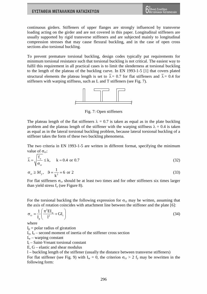
continuous girders. Stiffeners of upper flanges are strongly influenced by transverse loading acting on the girder and are not covered in this paper. Longitudinal stiffeners are usually supported by rigid transverse stiffeners and are subjected mainly to longitudinal compression stresses that may cause flexural buckling, and in the case of open cross sections also torsional buckling. To prevent premature torsional buckling, design codes typically put requirements for minimum torsional resistance such that torsional buckling is not critical. The easiest way to fulfil this requirement in all practical cases is to limit the slenderness at torsional buckling to the length of the plateau of the buckling curve. In EN 1993-1-5 [1] that covers plated structural elements the plateau length is set to λ= 0.7 for flat stiffeners and λ= 0.4 for stiffeners with warping stiffness, such as L and T stiffeners (see Fig. 7).
Fig. 7: Open stiffeners The plateau length of the flat stiffeners λ = 0.7 is taken as equal as in the plate buckling problem and the plateau length of the stiffener with the warping stiffness λ = 0.4 is taken as equal as in the lateral torsional buckling problem, because lateral torsional buckling of a stiffener takes the form of these two buckling phenomena. The two criteria in EN 1993-1-5 are written in different format, specifying the minimum value of σcr:
y
cr
fk, k 0.4 or 0.7λ = ≤ =
σ (32)
cr y 2
1f , 6 or 2
kσ ≥ ϑ ϑ = = (33)
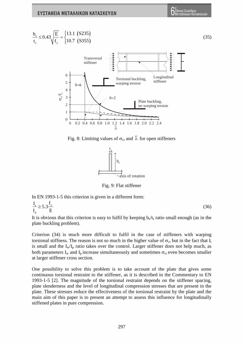
For flat stiffeners σcr should be at least two times and for other stiffeners six times larger than yield stress fy (see Figure 8). For the torsional buckling the following expression for σcr may be written, assuming that the axis of rotation coincides with attachment line between the stiffener and the plate [6]:
2w
cr t2p
EI1GI
I l
πσ = +
(34)
where Ip = polar radius of giratation Iy, Iz – second moment of inertia of the stiffener cross section Iw – warping constant It – Saint-Venant torsional constant E, G – elastic and shear modulus l – buckling length of the stiffener (usually the distance between transverse stiffeners) For flat stiffener (see Fig. 9) with Iw = 0, the criterion σcr > 2 fy may be rewritten in the following form:
297
( )
( )s
s y
13.1 S235b E0.43
10.7 S355t f
≤ =
(35)
0 0.2 0.4 0.6 0.8 1.0 1.2 1.4 1.6 1.82.0 2.2 2.4
1
2
3
4
5
6
0
λ
σcr
y/ f
ϑ=2
ϑ=6
Torsional buckling,warping torsion
Plate buckling,no warping torsion
Longitudinalstiffener
Transversalstiffener
Fig. 8: Limiting values of σcr and λ for open stiffeners
bs
ts
axis of rotation
Fig. 9: Flat stiffener In EN 1993-1-5 this criterion is given in a different form:
yt
p
fI5.3
I E≥ (36)
It is obvious that this criterion is easy to fulfil by keeping bs/ts ratio small enough (as in the plate buckling problem). Criterion (34) is much more difficult to fulfil in the case of stiffeners with warping torsional stiffness. The reason is not so much in the higher value of σcr but in the fact that It is small and the Iw/Ip ratio takes over the control. Larger stiffener does not help much, as both parameters Iw and Ip increase simultaneously and sometimes σcr even becomes smaller at larger stiffener cross section. One possibility to solve this problem is to take account of the plate that gives some continuous torsional restraint to the stiffener, as it is described in the Commentary to EN 1993-1-5 [2]. The magnitude of the torsional restraint depends on the stiffener spacing, plate slenderness and the level of longitudinal compression stresses that are present in the plate. These stresses reduce the effectiveness of the torsional restraint by the plate and the main aim of this paper is to present an attempt to assess this influence for longitudinally stiffened plates in pure compression.
298
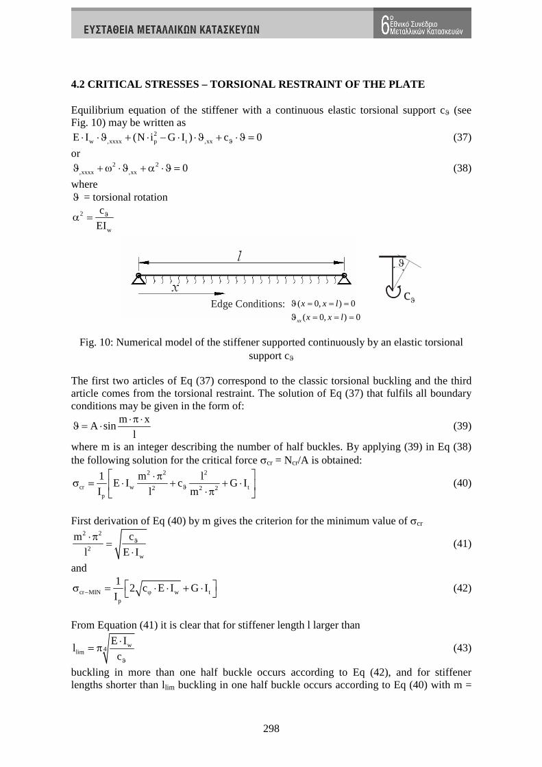
4.2 CRITICAL STRESSES – TORSIONAL RESTRAINT OF THE PLATE Equilibrium equation of the stiffener with a continuous elastic torsional support cϑ (see Fig. 10) may be written as
2w ,xxxx p t ,xxE I (N i G I ) c 0
ϑ⋅ ⋅ϑ + ⋅ − ⋅ ⋅ϑ + ⋅ϑ = (37)
or 2 2
,xxxx ,xx 0ϑ +ω ⋅ϑ +α ⋅ϑ = (38)
where ϑ = torsional rotation
2
w
c
EIϑ
α =
( 0, ) 0
( 0, ) 0xx
x x l
x x l
ϑ
ϑ
= = =
= = =
Edge Conditions:
ϑ
cϑ
Fig. 10: Numerical model of the stiffener supported continuously by an elastic torsional support cϑ
The first two articles of Eq (37) correspond to the classic torsional buckling and the third article comes from the torsional restraint. The solution of Eq (37) that fulfils all boundary conditions may be given in the form of:
m xA sin
l
⋅ π ⋅ϑ = ⋅ (39)
where m is an integer describing the number of half buckles. By applying (39) in Eq (38) the following solution for the critical force σcr = Ncr/A is obtained:
2 2 2
cr w t2 2 2p
1 m lE I c G I
I l mϑ ⋅ π
σ = ⋅ + + ⋅ ⋅π (40)
First derivation of Eq (40) by m gives the criterion for the minimum value of σcr
2 2
2w
cm
l E Iϑ
⋅ π
=
⋅
(41)
and
cr MIN w tp
12 c E I G I
I− ϕ σ = ⋅ ⋅ + ⋅ (42)
From Equation (41) it is clear that for stiffener length l larger than
w4lim
E Il
cϑ
⋅
= π (43)
buckling in more than one half buckle occurs according to Eq (42), and for stiffener lengths shorter than llim buckling in one half buckle occurs according to Eq (40) with m =
299
1. Initial torsional stiffness that is not affected by compression stresses may be determined by straight forward static analysis. For only one stiffener cϑ0 is given by
3
0
E tc
2 bϑ
⋅
=
⋅
(44)
and for a large number of equally spaced stiffeners by 3
0
E tc
3 bϑ
⋅
=
⋅
(45)
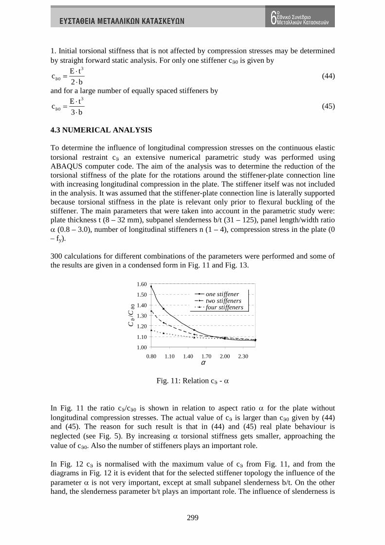
4.3 NUMERICAL ANALYSIS To determine the influence of longitudinal compression stresses on the continuous elastic torsional restraint cϑ an extensive numerical parametric study was performed using ABAQUS computer code. The aim of the analysis was to determine the reduction of the torsional stiffness of the plate for the rotations around the stiffener-plate connection line with increasing longitudinal compression in the plate. The stiffener itself was not included in the analysis. It was assumed that the stiffener-plate connection line is laterally supported because torsional stiffness in the plate is relevant only prior to flexural buckling of the stiffener. The main parameters that were taken into account in the parametric study were: plate thickness t (8 – 32 mm), subpanel slenderness b/t (31 – 125), panel length/width ratio α (0.8 – 3.0), number of longitudinal stiffeners n (1 – 4), compression stress in the plate (0 – fy). 300 calculations for different combinations of the parameters were performed and some of the results are given in a condensed form in Fig. 11 and Fig. 13.
1.00
1.10
1.20
1.30
1.40
1.50
1.60
0.80 1.10 1.40 1.70 2.00 2.30α
Cϑ /C
ϑ0
one stiffenertwo stiffenersfour stiffeners
Fig. 11: Relation cϑ - α In Fig. 11 the ratio cϑ/cϑ0 is shown in relation to aspect ratio α for the plate without longitudinal compression stresses. The actual value of cϑ is larger than cϑ0 given by (44) and (45). The reason for such result is that in (44) and (45) real plate behaviour is neglected (see Fig. 5). By increasing α torsional stiffness gets smaller, approaching the value of cϑ0. Also the number of stiffeners plays an important role. In Fig. 12 cϑ is normalised with the maximum value of cϑ from Fig. 11, and from the diagrams in Fig. 12 it is evident that for the selected stiffener topology the influence of the parameter α is not very important, except at small subpanel slenderness b/t. On the other hand, the slenderness parameter b/t plays an important role. The influence of slenderness is

300
summarized in Fig. 13. Regarding the compression stresses in the plate, as expected in all cases, elastic torsional stiffness reduces with increasing stress. Fig. 13 gives results for 1, 2 and 4 stiffeners at α = 2.0 for different slenderness parameters b/t. In the nondimensional form the influence of the number of the stiffeners is small and more pronounced only for small slenderness parameters b/t.
b/t = 31.25
0.00
0.20
0.40
0.60
0.80
1.00
0.00 0.20 0.40 0.60 0.80 1.00
σ/fy
Cϑ/
Cϑ,
max α = 0.80
α = 1.00α = 1.50α = 2.00α = 2.50
b/t = 58.82
0.00
0.20
0.40
0.60
0.80
1.00
0.00 0.20 0.40 0.60 0.80 1.00
σ/fy
Cϑ/
Cϑ
, ma
x
α = 0.80α = 1.00α = 1.50α = 2.00α = 2.50
b/t = 90.91
0.00
0.20
0.40
0.60
0.80
1.00
0.00 0.20 0.40 0.60 0.80 1.00σ/fy
Cϑ/
Cϑ
ma
x
α = 0.80α = 1.00α = 1.50α = 2.00α = 2.50
b/t = 125
0.00
0.20
0.40
0.60
0.80
1.00
0.00 0.20 0.40 0.60 0.80 1.00σ/fy
Cϑ/
Cϑ,
ma
xα = 0.80α = 1.00α = 1.50α = 2.00α = 2.50
Fig. 12: Relation cϑ - compression stress at different subpanel slenderness and values of α for one stiffener
α = 2.00α = 2.00α = 2.00α = 2.00
0.00
0.20
0.40
0.60
0.80
1.00
0.00 0.20 0.40 0.60 0.80 1.00σ/fy
Cϑ/
Cϑ,
max
b/t=125 one stiffener b/t=125 two stiffeners b/t=125 four stiffenersb/t=90.91 one stiffener b/t=90.91 two stiffeners b/t=90.91 four stiffenersb/t=58.82 one stiffener b/t=58.82 two stiffeners b/t=58.82 four stiffenersb/t=31.25 one stiffener b/t=31.25 two stiffeners b/t=31.25 four stiffeners
Fig. 13: Relation cϑ - compression force at α = 2 for 1, 2 and 4 stiffeners and different values of slenderness parameter b/t

301
4.4 ANALYTICAL EXPRESSIONS FOR C ϑ For a practical application simple analytical expressions were derived based on the results of numerical calculations. It is obvious that all the main parameters should be included in the analytical expressions:
y
bc c , ,
t fϑ ϑ
σ= α
(46)
Numerical results lead us to the conclusion that two separate functions should be used, one to describe dependence on α and the number of stiffeners, and the other to cover parameters b/t and σ/fy:
0 1 2y
bc c f ( ) f ,
t fϑ ϑ
σ= ⋅ α ⋅
. (47)
f1 differs with the number of stiffeners (see Fig. 11) and f2 can be assumed to be independent of the number of the stiffeners. Functions f1 and f2 were determined with the help of the computer code MATHEMATICA applying the least square method. For f1(α) the following solution was obtained
( )1 2
1 1f C
A Bα = + +
⋅α ⋅α
(48)
Coefficients A, B and C (rounded values) are listed in Table 1.
1 2 4
A 3,0000 5,0000 50,0000B 0,0000 0,0000 10,0000C 1,0000 1,0000 1,0000
Number of Stiffeners
Table 1: Values of coefficients A, B and C from f1(α) f2 (b/t, σ/fy) can be expressed as an exponential function. After some simplifications of the solution obtained by MATHEMATICA a possible solution may be
y
1 b
30,9 t f
2y
bf , e
t f
σ
− ⋅ ⋅ σ=
(49)
Final expressions for elastic torsional restraint are given in Table 2. In Fig. 14 and Fig. 15 a comparison between numerical and analytical values is shown and a good agreement is achieved for f1 (Fig. 14) and f2 (Fig. 15). A correlation diagram between all the numerical results and the derived analytical expressions is plotted in Fig. 16. A good correlation with safe-sided results is obtained. Further safe-sided simplification is possible by neglecting favourable plate behaviour shown in Fig. 11. f1 is then taken as equal to 1 and for all panel topologies the elastic torsional stiffness can be written as

302
y
1 b
30.9 t f
0c c e
σ− ⋅ ⋅
ϑ ϑ= ⋅ (50)
which is a very simple expression suitable for everyday engineering practice.
Number of stiffeners
cϑ
1 y
1 b330.9 t f
2 2
E t 11 e
2 b (1 ) 3
σ− ⋅ ⋅
⋅ + ⋅ ⋅ ⋅ − ν ⋅α
2 y
1 b330.9 t f
2 2
E t 11 e
2,5 b (1 ) 5
σ− ⋅ ⋅
⋅ + ⋅ ⋅ ⋅ − ν ⋅α
3 or more y
1 b3
30.9 t f
2 22
2
E t 1 11 e
h3 b (1 ) h10 505 b 25 b
σ− ⋅ ⋅
⋅ + + ⋅ ⋅ ⋅ − ν
⋅ α ⋅ ⋅ α ⋅ ⋅ ⋅
Table 2: Expressions for cϑ for different number of stiffeners
1.00
1.10
1.20
1.30
1.40
1.50
1.60
0.80 1.30 1.80 2.30
one stiffenerone stiffener - equationtwo stiffenerstwo stiffeners - equationfour stiffenersfour stiffeners - equation
α
c/c ϑ
ϑ0
0.00
0.20
0.40
0.60
0.80
1.00
0.00 0.20 0.40 0.60 0.80 1.00
b/t=31,25 b/t=31,25 - equationb/t=58,82 b/t=58,82 - equationb/t=90,91 b/t=90,91 - equationb/t=125,00 b/t=125,00 - equation
c/c ϑ
ϑ0
σ/fy
Fig. 14: Function f1 in comparison to numerical results
Fig. 15: Function f2 in comparison to numerical results

303
0.00
0.20
0.40
0.60
0.80
1.00
1.20
0.00 0.20 0.40 0.60 0.80 1.00 1.20
Numerical Results for cϑ
Ana
lytic
alex
pres
sion
for
c ϑ
One stiffener
Two stiffeners
Four stiffeners
Fig. 16: Correlation between numerical and analytical results 5. CONCLUSIONS The paper presents the design of rigid transverse stiffeners of plate girders according to Eurocode standard EN 1993-1-5. The background of the design rules from EN 1993-1-5 is presented and additional rules for single sided stiffeners are given. Although the design rules are based on strength and deformability checks taking account of second order effect and initial geometric imperfections, they can be presented in relatively simple formats, suitable for everyday design practice. The paper also gives information on how to prevent torsional buckling of longitudinal and transverse stiffeners. For this purpose based on extensive numerical study, simple analytical expressions are derived for elastic torsional stiffness of the plate that may be used in the calculation of the critical torsional buckling stress of a stiffener. By doing this a critical buckling stress may be increased significantly and the design criterion (33) may be fulfilled more easily. 6. REFERENCES
[1] CEN, EN 1993-1-5, Design of steel structures – Plated structural elements [2] B. JOHANSSON, R. MAQUOI, G. SEDLACEK, C. MUELLER, D. BEG,
“Commentary and worked examples to EN 1993-1-5 - Plated structural elements”, JRC Report 38239, EUR 22898 EN
[3] D. BEG, N. ALEKSIČ “Bending resistance of longitudinally stiffened plate girdes, 7th international conference on steel bridges, Guimaraes, 2008, pp. II-187 – II-196.
[4] C.R. HENDY, F. PRESTA “Transverse web stiffeners and shear moment interaction for steel plate girder bridges“,7th international conference on steel bridges, Guimaraes, 2008, pp. II-215 – II-230.
[5] J. DUJC “Transverse stiffeners of plate girder”, Diploma thesis, University of Ljubljana, Faculty of Civil and Geodetic Engineering, 2005
[6] F. SINUR “ Torsional resistance of longitudinal and transverse stiffeners of plate girders”, Diploma Thesis, University of Ljubljana, Faculty of Civil and Geodetic Engineering, 2006