plate-and-frame heat exchangers -...
TRANSCRIPT

This document is under review as revision to an API Standard; it is under consideration within an API technical committee but has not received all approvals required for publication. This document shall not be reproduced or circulated or quoted, in whole or in part, outside of API committee activities except with the approval of the Chairman of the committee having jurisdiction and staff of the API Standards Dept. Copyright API. All rights reserved.
Plate-and-frame Heat Exchangers API STANDARD 667 PROPOSED FIRST EDITION, XXXX 2018
FOR REVIEW & COMMENT ONLY;
NOT FOR DISTRIBUTION
This document is under review as revision to an API Standard; it is under consideration within an API technical committee but has not received all approvals required for publication. This document shall not be reproduced or circulated or quoted, in whole or in part, outside of API committee activities except with the approval of the Chairman of the committee having jurisdiction and staff of the API Standards Dept. Copyright API. All rights reserved.
Plate-and-frame Heat Exchangers
ii
Special Notes
API publications necessarily address problems of a general nature. With respect to particular circumstances, local, state, and federal laws and regulations should be reviewed.
Neither API nor any of API's employees, subcontractors, consultants, committees, or other assignees make any warranty or representation, either express or implied, with respect to the accuracy, completeness, or usefulness of the information contained herein, or assume any liability or responsibility for any use, or the results of such use, of any information or process disclosed in this publication. Neither API nor any of API's employees, subcontractors, consultants, or other assignees represent that use of this publication would not infringe upon privately owned rights.
API publications may be used by anyone desiring to do so. Every effort has been made by the Institute to assure the accuracy and reliability of the data contained in them; however, the Institute makes no representation, warranty, or guarantee in connection with this publication and hereby expressly disclaims any liability or responsibility for loss or damage resulting from its use or for the violation of any authorities having jurisdiction with which this publication may conflict.
API publications are published to facilitate the broad availability of proven, sound engineering and operating practices. These publications are not intended to obviate the need for applying sound engineering judgment regarding when and where these publications should be utilized. The formulation and publication of API publications is not intended in any way to inhibit anyone from using any other practices.
Any manufacturer marking equipment or materials in conformance with the marking requirements of an API standard is solely responsible for complying with all the applicable requirements of that standard. API does not represent, warrant, or guarantee that such products do in fact conform to the applicable API standard.
All rights reserved. No part of this work may be reproduced, translated, stored in a retrieval system, or transmitted by
any means, electronic, mechanical, photocopying, recording, or otherwise, without prior written permission from the
publisher. Contact the Publisher, API Publishing Services, 1220 L Street, NW, Washington, DC 20005.
Copyright © 2013 American Petroleum Institute
FOR REVIEW & COMMENT ONLY;
NOT FOR DISTRIBUTION

This document is under review as revision to an API Standard; it is under consideration within an API technical committee but has not received all approvals required for publication. This document shall not be reproduced or circulated or quoted, in whole or in part, outside of API committee activities except with the approval of the Chairman of the committee having jurisdiction and staff of the API Standards Dept. Copyright API. All rights reserved.
Plate-and-frame Heat Exchangers
iii
Foreword
Nothing contained in any API publication is to be construed as granting any right, by implication or otherwise,
for the manufacture, sale, or use of any method, apparatus, or product covered by letters patent. Neither
should anything contained in the publication be construed as insuring anyone against liability for
infringement of letters patent.
This document was produced under API standardization procedures that ensure appropriate notification and
participation in the developmental process and is designated as an API standard. Questions concerning the
interpretation of the content of this publication or comments and questions concerning the procedures under
which this publication was developed should be directed in writing to the Director of Standards, American
Petroleum Institute, 1220 L Street, NW, Washington, DC 20005. Requests for permission to reproduce or
translate all or any part of the material published herein should also be addressed to the director.
Generally, API standards are reviewed and revised, reaffirmed, or withdrawn at least every five years. A
one-time extension of up to two years may be added to this review cycle. Status of the publication can be
ascertained from the API Standards Department, telephone (202) 682-8000. A catalog of API publications
and materials is published annually by API, 1220 L Street, NW, Washington, DC 20005.
Suggested revisions are invited and should be submitted to the Standards Department, API, 1220 L Street,
NW, Washington, DC 20005, [email protected].
FOR REVIEW & COMMENT ONLY;
NOT FOR DISTRIBUTION

This document is under review as revision to an API Standard; it is under consideration within an API technical committee but has not received all approvals required for publication. This document shall not be reproduced or circulated or quoted, in whole or in part, outside of API committee activities except with the approval of the Chairman of the committee having jurisdiction and staff of the API Standards Dept. Copyright API. All rights reserved.
Plate-and-frame Heat Exchangers
iv
FOR REVIEW & COMMENT ONLY;
NOT FOR DISTRIBUTION
This document is under review as revision to an API Standard; it is under consideration within an API technical committee but has not received all approvals required for publication. This document shall not be reproduced or circulated or quoted, in whole or in part, outside of API committee activities except with the approval of the Chairman of the committee having jurisdiction and staff of the API Standards Dept. Copyright API. All rights reserved.
Plate-and-frame Heat Exchangers
v
Contents Page
Foreword ............................................................................................................................................................ iii
Introduction ...................................................................................................................................................... vii
1 Scope...................................................................................................................................................... 1
2 Normative References .......................................................................................................................... 1
3 Terms and Definitions .......................................................................................................................... 1
4 General ................................................................................................................................................... 6
5 Proposal Information Required ........................................................................................................... 6
6 Drawings and Other Data Requirements ............................................................................................ 8 6.1 Outline Drawings and Other Supporting Data ................................................................................... 8 6.2 Information Required After Outline Drawings Are Reviewed ........................................................... 9 6.3 Reports and Records ................................................................................ Error! Bookmark not defined.
7 Design ........................................................................................................ Error! Bookmark not defined. 7.1 General ................................................................................................................................................. 11 7.2 Design Temperature ........................................................................................................................... 11 7.3 Design Pressure .................................................................................................................................. 11 7.4 Fouling Margin .................................................................................................................................... 11 7.5 Corrosion Allowance .......................................................................................................................... 11 7.6 Components ........................................................................................................................................ 12 7.7 Connections ........................................................................................................................................ 13 7.8 Plate Gaskets ....................................................................................................................................... 16
8 Materials ............................................................................................................................................... 17 8.1 General ................................................................................................................................................. 17 8.2 Requirements for Carbon Steel in Sour or Wet Hydrogen Sulfide Service .................................. 17
9 Fabrication ........................................................................................................................................... 18 9.1 Welding ................................................................................................................................................ 18 9.2 Plate Gasket Installation..................................................................................................................... 19 9.3 Assembly ............................................................................................................................................. 20
10 Inspection and Testing ....................................................................................................................... 20 10.1 Quality Control .................................................................................................................................... 20 10.2 Hydrostatic Testing ............................................................................................................................. 21 10.3 Nameplates .......................................................................................................................................... 22
11 Preparation for Shipment ................................................................................................................... 22
Annex A (informative) Recommended Practice............................................................................................. 24 A.1 General ................................................................................................................................................. 24 A.2 Proposal Information Required ......................................................................................................... 24 A.3 Design .................................................................................................................................................. 25 A.4 Fabrication ........................................................................................................................................... 34 A.5 Nameplates-Guidance to 10.3.1 ......................................................................................................... 35 A.6 Protection for Shipment—Guidance to 11.2..................................................................................... 35
FOR REVIEW & COMMENT ONLY;
NOT FOR DISTRIBUTION

This document is under review as revision to an API Standard; it is under consideration within an API technical committee but has not received all approvals required for publication. This document shall not be reproduced or circulated or quoted, in whole or in part, outside of API committee activities except with the approval of the Chairman of the committee having jurisdiction and staff of the API Standards Dept. Copyright API. All rights reserved.
Plate-and-frame Heat Exchangers
vi
Annex B (informative) Plate-and-frame Heat Exchanger Checklist ............................................................. 36
Annex C (informative) Plate-and-frame Heat Exchanger Datasheets ......................................................... 38
Bibliography ..................................................................................................................................................... 46
FOR REVIEW & COMMENT ONLY;
NOT FOR DISTRIBUTION
This document is under review as revision to an API Standard; it is under consideration within an API technical committee but has not received all approvals required for publication. This document shall not be reproduced or circulated or quoted, in whole or in part, outside of API committee activities except with the approval of the Chairman of the committee having jurisdiction and staff of the API Standards Dept. Copyright API. All rights reserved.
Plate-and-frame Heat Exchangers
vii
Introduction
It is necessary that users of this standard be aware that further or differing requirements can be needed for individual applications. This standard is not intended to inhibit a vendor from offering, or the purchaser from accepting, alternative equipment or engineering solutions for the individual application. This can be particularly applicable where there is an innovative or developing technology. Where an alternative is offered, it is the responsibility of the vendor to identify any variations from this standard and provide details.
This standard has been re-numbered; it was previously published as API standard 662, part 1.
A recommended practice is included within this part of this standard (see Annex A).
This standard requires the purchaser to specify certain details and features.
A bullet () at the beginning of a paragraph or subsection indicates a requirement for the purchaser to make a decision or provide information (for information, a checklist is provided in Annex B).
In this standard, where practical, US Customary units are included in parentheses for information.
FOR REVIEW & COMMENT ONLY;
NOT FOR DISTRIBUTION

FOR REVIEW & COMMENT ONLY;
NOT FOR DISTRIBUTION

This document is under review as revision to an API Standard; it is under consideration within an API technical committee but has not received all approvals required for publication. This document shall not be reproduced or circulated or quoted, in whole or in part, outside of API committee activities except with the approval of the Chairman of the committee having jurisdiction and staff of the API Standards Dept. Copyright API. All rights reserved.
Plate-and-frame Heat Exchangers
1
Plate-and-frame Heat Exchangers
1 Scope
This standard gives requirements and recommendations for the mechanical design, materials selection, fabrication, inspection, testing, and preparation for shipment of plate-and-frame heat exchangers for use in petroleum, petrochemical and natural gas industries.
It is applicable to gasketed and semi-welded plate-and-frame heat exchangers.
This document does not cover the requirements for fully welded plate-and-frame, fully welded plate-block or plate-in-shell heat exchangers.
2 Normative References
The following referenced documents are indispensable for the application of this document. For dated references, only the edition cited applies. For undated references, the latest edition of the referenced document (including any amendments) applies.
ISO 8501-1 1, Preparation of steel substrates before application of paints and related products—Visual assessment of surface cleanliness —Part 1: Rust grades and preparation grades of uncoated steel substrates and of steel substrates after overall removal of previous coatings
3 Terms and Definitions
For the purposes of this document, the following terms and definitions apply.
3.1 channel Fluid flow passage created by two adjacent plates.
Note: see Figure 3.
3.2 cyclic service A process operation with periodic variation in temperature, pressure, and/or flow rate.
3.3 drip tray Tray that is able to collect droplets from an entire heat exchanger plate pack.
3.4 end plate Plate which prevent the fluids in a plate-and-frame heat exchanger from contacting the fixed and removable covers.
NOTE There are two end plates, one at each end of the plate-and-frame heat exchanger.
1 International Organization for Standardization, 1, ch. de la Voie-Creuse, Case postale 56, CH-1211 Geneva 20,
Switzerland, www.iso.org.
FOR REVIEW & COMMENT ONLY;
NOT FOR DISTRIBUTION
This document is under review as revision to an API Standard; it is under consideration within an API technical committee but has not received all approvals required for publication. This document shall not be reproduced or circulated or quoted, in whole or in part, outside of API committee activities except with the approval of the Chairman of the committee having jurisdiction and staff of the API Standards Dept. Copyright API. All rights reserved.
Plate-and-frame Heat Exchangers
2
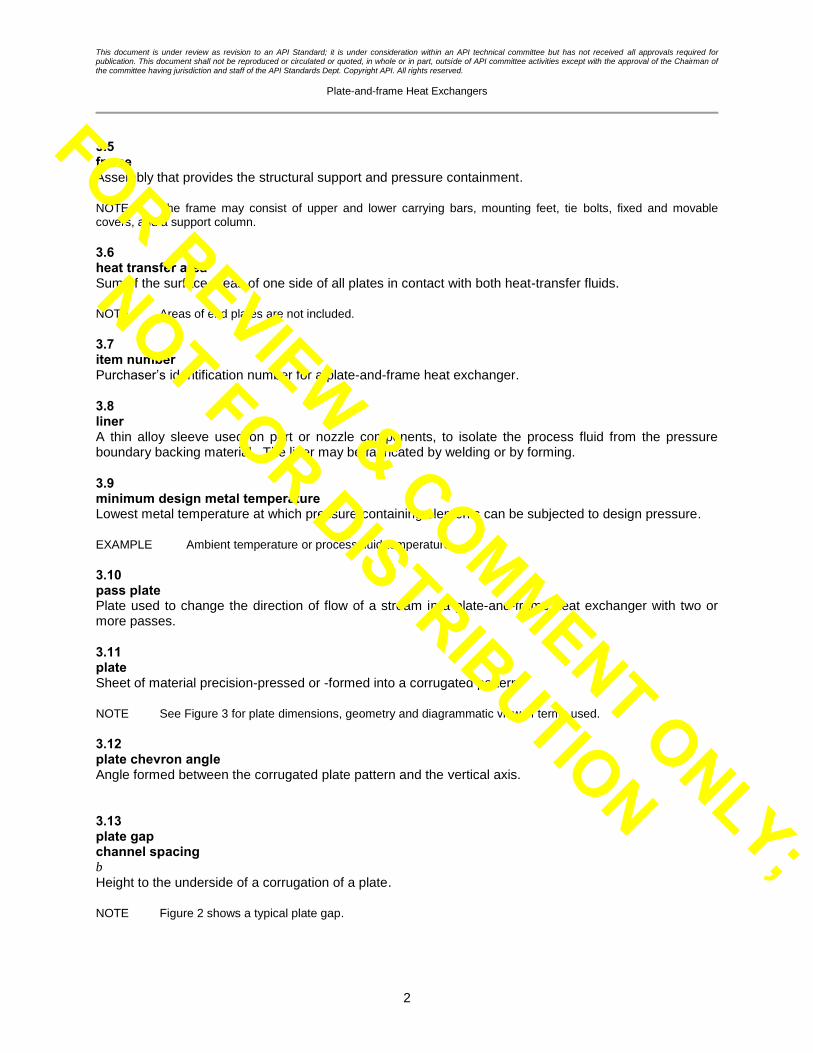
3.5 frame Assembly that provides the structural support and pressure containment.
NOTE The frame may consist of upper and lower carrying bars, mounting feet, tie bolts, fixed and movable covers, and a support column.
3.6 heat transfer area Sum of the surface areas of one side of all plates in contact with both heat-transfer fluids.
NOTE Areas of end plates are not included.
3.7 item number Purchaser’s identification number for a plate-and-frame heat exchanger.
3.8 liner A thin alloy sleeve used on port or nozzle components, to isolate the process fluid from the pressure boundary backing material. The liner may be fabricated by welding or by forming.
3.9 minimum design metal temperature Lowest metal temperature at which pressure-containing elements can be subjected to design pressure.
EXAMPLE Ambient temperature or process fluid temperature.
3.10 pass plate Plate used to change the direction of flow of a stream in a plate-and-frame heat exchanger with two or more passes.
3.11 plate Sheet of material precision-pressed or -formed into a corrugated pattern.
NOTE See Figure 3 for plate dimensions, geometry and diagrammatic view of terms used.
3.12 plate chevron angle Angle formed between the corrugated plate pattern and the vertical axis.
3.13 plate gap channel spacing b
Height to the underside of a corrugation of a plate.
NOTE Figure 2 shows a typical plate gap.
FOR REVIEW & COMMENT ONLY;
NOT FOR DISTRIBUTION

This document is under review as revision to an API Standard; it is under consideration within an API technical committee but has not received all approvals required for publication. This document shall not be reproduced or circulated or quoted, in whole or in part, outside of API committee activities except with the approval of the Chairman of the committee having jurisdiction and staff of the API Standards Dept. Copyright API. All rights reserved.
Plate-and-frame Heat Exchangers
3
3.14 plate pack Grouping of all plates contained within a frame.
3.15 plate-and-frame heat exchanger Assembly of a gasketed, semi-welded or welded plate pack and its supporting frame.
NOTE Figure 1 shows typical components of a plate-and-frame heat exchanger.
3.16 port Inlet or outlet opening in the plate.
3.17 pressure design code The recognized pressure vessel standard as specified or agreed by the purchaser.
EXAMPLE ASME BPVC Section VIII, EN 13445 (all parts).
3.18 semi-welded plate pair Two adjacent plates welded together where the weld replaces the function of a gasket.
NOTE Gaskets are used to seal adjacent semi-welded plate pairs.
3.19 shroud Removable covering for the top and sides of the plate pack of the plate-and-frame heat exchanger, which provides protection in the event of a spray leak or fire.
3.19 structural welding code The recognized structural welding code as specified or agreed by the purchaser.
3.20 tie bolt Used to compress plate pack, movable and fixed covers to contain pressure.
3.21 welded plate pack Plate pack where the gaskets have been replaced by welds.
FOR REVIEW & COMMENT ONLY;
NOT FOR DISTRIBUTION

This document is under review as revision to an API Standard; it is under consideration within an API technical committee but has not received all approvals required for publication. This document shall not be reproduced or circulated or quoted, in whole or in part, outside of API committee activities except with the approval of the Chairman of the committee having jurisdiction and staff of the API Standards Dept. Copyright API. All rights reserved.
Plate-and-frame Heat Exchangers
4
Key
1 mounting feet 6 tie bolts 2 plate pack 7 guide bar (bottom)
3 fixed cover 8 carrying bar (top) 4 movable cover 9 connections, studded or flanged
5 support column 10 tie nuts
Figure 1—Typical Single-pass Plate-and-frame Heat Exchanger
Colin Weil Comment #1: note that API have edited these figures. Seem ok
FOR REVIEW & COMMENT ONLY;
NOT FOR DISTRIBUTION

This document is under review as revision to an API Standard; it is under consideration within an API technical committee but has not received all approvals required for publication. This document shall not be reproduced or circulated or quoted, in whole or in part, outside of API committee activities except with the approval of the Chairman of the committee having jurisdiction and staff of the API Standards Dept. Copyright API. All rights reserved.
Plate-and-frame Heat Exchangers
5
Where b = p t
Key
b plate depth
b x 2 plate gap t plate thickness
p compressed pitch per plate
Figure 2—Plate Gap
Figure 3 — Plate Dimensions, Geometry and Diagrammatic View of Terms Used
KEY
1 Chevron angle, relative to vertical
2 Channel flow width (w), measured to the inside gasket edge
3 Port diameter,
4 Port center-to-center distance, horizontal
5 Port center-to-center distance, vertical
6 Single plate heat transfer area, shaded region
FOR REVIEW & COMMENT ONLY;
NOT FOR DISTRIBUTION

This document is under review as revision to an API Standard; it is under consideration within an API technical committee but has not received all approvals required for publication. This document shall not be reproduced or circulated or quoted, in whole or in part, outside of API committee activities except with the approval of the Chairman of the committee having jurisdiction and staff of the API Standards Dept. Copyright API. All rights reserved.
Plate-and-frame Heat Exchangers
6
4 General
4.1 The pressure design code shall be specified or agreed by the purchaser. Pressure components (i.e. covers, tie bolts, tie nuts and connections) shall comply with the pressure design code and the supplemental requirements in this standard.
4.2 The structural welding code shall be specified or agreed by the purchaser.
4.3 Annex A provides some recommended mechanical and design details for information. Annex A also includes some precautions for consideration when specifying fouling margin, fireproof shrouds and plate gaskets.
4.4 The vendor shall comply with the applicable local regulations specified by the purchaser.
4.5 The purchaser shall specify if the service is designated as sour in accordance with NACE MR0175 (all parts) for oil and gas production facilities and natural gas processing plants or is designated as wet hydrogen sulfide service in accordance with NACE MR0103 for other applications (e.g. petroleum refineries, LNG plants, and chemical plants), in which case all carbon steel materials and welds in contact with the process fluid shall meet the requirements of the applicable standard to mitigate potential for sulfide stress cracking (SSC). Identification of the complete set of materials, qualification, fabrication, and testing specifications to prevent in-service environmental cracking is the responsibility of the user (purchaser). See A.1.1 for guidance on sour or wet hydrogen sulfide service.
4.6 The purchaser shall specify if the requirements of 4.5, and the related clauses for H2S and sour service, shall be applied where carbon steel is isolated from process fluid contact by the use of liners.
4.7 The purchaser shall specify if cyclic service design is required.
4.8 If cyclic service is specified, the purchaser shall specify the type and magnitude of variation in pressure, temperature and flow rate, the time for the variation (hours, weeks, months, etc.) and the number of cycles or frequency for this variation expected during the life of the equipment. The extent and acceptance criteria of any required analysis shall be subject to the agreement of the purchaser. See A.3.2 for guidance on cyclic service.
5 Proposal Information Required
5.1 The vendor's proposal shall include, as a minimum, the following information:
a) data sheet;
b) preliminary general arrangement drawing including overall dimensional information and weight;
c) nozzle sizes and locations;
d) gasket material and attachment method;
e) plate material, thickness and dimensions;
f) number of plates.
5.2 For components that are not fully identified by Section 3, the vendor shall describe the details of construction and assembly.
FOR REVIEW & COMMENT ONLY;
NOT FOR DISTRIBUTION

This document is under review as revision to an API Standard; it is under consideration within an API technical committee but has not received all approvals required for publication. This document shall not be reproduced or circulated or quoted, in whole or in part, outside of API committee activities except with the approval of the Chairman of the committee having jurisdiction and staff of the API Standards Dept. Copyright API. All rights reserved.
Plate-and-frame Heat Exchangers
7
5.3 The vendor shall include a detailed description of any exception to the requirements of the purchaser's enquiry.
5.4 The first-time use of a plate-and-frame heat exchanger design, component or material by the vendor for the purchaser’s intended service shall be clearly indicated by the vendor.
5.5 The vendor shall state the anticipated life of the proposed gaskets in the specified service considering the operating pressures and temperatures. The vendor shall also state the anticipated life in storage and any special requirements for gasket storage required to maintain gasket shelf-life.
5.6 The vendor shall state the method of support used for the movable cover.
5.7 The vendor shall supply a recommended spare parts list for each plate-and-frame heat exchanger.
5.8 If a fireproof shroud is specified, the plate-and-frame heat exchanger vendor shall submit proof that the proposed design has passed suitable type testing.
5.9 The vendor shall guarantee the thermal and hydraulic performance of the exchangers offered.
5.10 When specified by the purchaser, the vendor shall provide the following data that will allow the purchaser to perform a thermal verification: See A.2.1 for additional guidance on thermal and hydraulic design. See Figure 3 for diagrammatic view of terms used.
a) Plate information:
1) chevron angle's used in the design;
2) heat transfer plate thickness;
3) heat transfer area per plate;
4) number of effective heat transfer plates;
5) plate material.
b) Port information:
1) port diameters;
2) port center-to-center distance, horizontal;
3) port center-to-center distance, vertical;
4) port arrangement, locations of inlets and outlets for hot and cold streams.
c) Plate pack information:
1) channel spacing for each stream;
2) channel width;
3) number of packs in series;
FOR REVIEW & COMMENT ONLY;
NOT FOR DISTRIBUTION

This document is under review as revision to an API Standard; it is under consideration within an API technical committee but has not received all approvals required for publication. This document shall not be reproduced or circulated or quoted, in whole or in part, outside of API committee activities except with the approval of the Chairman of the committee having jurisdiction and staff of the API Standards Dept. Copyright API. All rights reserved.
Plate-and-frame Heat Exchangers
8
4) number of packs in parallel;
5) number of hot fluid passes per pack;
6) number of cold fluid passes per pack;
7) number of channels in each hot fluid pass (can be different for each pass);
8) number of channels in each cold fluid pass (can be different for each pass);
9) flow configuration
i.) flow in first pass (countercurrent/cocurrent);
ii.) inlet port locations (same end/opposite end);
iii.) diagonal or parallel flow on each plate;
iv.) plate type(s) for the channel configuration in each pack.
5.11 The vendor shall supply the calculated pressure drop for the ports (combined inlet and outlet) as well as the overall pressure drop from nozzle-to-nozzle for each stream. See A.2.2.1 for additional guidance on port pressure drop.
5.12 The vendor shall provide port inlet and outlet flow velocities. See A.2.2.2 for additional guidance on the flow within ports.
5.13 The vendor shall provide details of connections including any lining, cladding and method of attachment to covers.
6 Drawings and Other Data Requirements
6.1 Outline Drawings and Other Supporting Data
6.1.1 The vendor shall submit, for review by the purchaser, outline drawings for each plate-and-frame heat exchanger unit. The drawings shall include the following information:
a) service, item number, project name and location, purchaser’s order number, vendor’s shop order number and other special identification numbers;
b) design pressure, test pressure, maximum design temperature, minimum design metal temperature and any restriction on testing or operation of the heat exchanger;
c) connection sizes, location, orientation, projection, direction of flow and, if flanged, the rating and facing including any lining, cladding and method of attachment to the covers;
d) dimensions and location of supports, including bolt holes and slots;
e) overall dimensions of the heat exchanger;
f) maximum and minimum compressed plate pack length (to ensure metal-to-metal plate contact);
FOR REVIEW & COMMENT ONLY;
NOT FOR DISTRIBUTION

This document is under review as revision to an API Standard; it is under consideration within an API technical committee but has not received all approvals required for publication. This document shall not be reproduced or circulated or quoted, in whole or in part, outside of API committee activities except with the approval of the Chairman of the committee having jurisdiction and staff of the API Standards Dept. Copyright API. All rights reserved.
Plate-and-frame Heat Exchangers
9
g) side clearance required for plate removal;
h) mass of the heat exchanger, empty and full of water;
i) mass of the heat exchanger at maximum plate capacity empty and full of water;
j) specified corrosion allowance for each side of the heat exchanger;
k) references to the applicable code and the purchaser’s specification;
l) requirements for NDE examination;
m) requirements for surface preparation and painting;
n) gasket materials and attachment method (e.g. glued, clip-on, etc.);
o) location of nameplates, lifting lugs, grounding lugs or other attachments;
p) location of center of gravity of the exchanger for empty and operating conditions;
q) material specifications and grades for all components;
r) forces and moments on connections as specified by the purchaser;
s) number of plates installed and maximum number of plates for specified frame;
6.1.2 The vendor shall provide bolt tightening procedures for review.
6.1.3 The vendor shall recommend the tools needed for the assembly and maintenance of the plate-and-frame heat exchanger.
6.1.4 The review of engineering documents by the purchaser shall not relieve the vendor of the responsibility of meeting the requirements of the purchase order.
6.2 Information Required After Outline Drawings Are Reviewed
6.2.1 Generic gasket details, including type and material, shall be provided.
6.2.2 Upon receipt of the purchaser’s review comments on the outline drawings, the vendor shall submit copies of all detailed (nonproprietary) drawings. These shall fully describe the heat exchanger and shall include at least the following information:
a) full views with dimensions and materials;
b) plate details, as specified in 5.10;
c) details of each pressure-retaining weld, including weld material, weld nominal thickness, weld location and applicable nondestructive examination method;
d) details of the weld joining semi-welded plate pairs, including weld location and applicable non-destructive examination;
FOR REVIEW & COMMENT ONLY;
NOT FOR DISTRIBUTION
This document is under review as revision to an API Standard; it is under consideration within an API technical committee but has not received all approvals required for publication. This document shall not be reproduced or circulated or quoted, in whole or in part, outside of API committee activities except with the approval of the Chairman of the committee having jurisdiction and staff of the API Standards Dept. Copyright API. All rights reserved.
Plate-and-frame Heat Exchangers
10
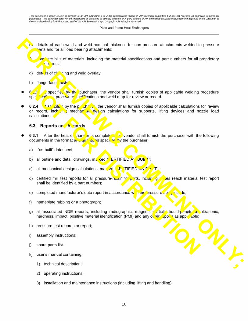
e) details of each weld and weld nominal thickness for non-pressure attachments welded to pressure parts and for all load bearing attachments;
f) complete bills of materials, including the material specifications and part numbers for all proprietary components;
g) details of cladding and weld overlay;
h) flange-face finish.
6.2.3 If specified by the purchaser, the vendor shall furnish copies of applicable welding procedure specifications, procedure qualifications and weld map for review or record.
6.2.4 If specified by the purchaser, the vendor shall furnish copies of applicable calculations for review or record, including mechanical design calculations for supports, lifting devices and nozzle load calculations.
6.3 Reports and Records
6.3.1 After the heat exchanger is completed, the vendor shall furnish the purchaser with the following documents in the format and quantities specified by the purchaser:
a) “as-built” datasheet;
b) all outline and detail drawings, marked “CERTIFIED AS-BUILT”;
c) all mechanical design calculations, marked "CERTIFIED AS-BUILT";
d) certified mill test reports for all pressure-retaining parts, including plates (each material test report shall be identified by a part number);
e) completed manufacturer’s data report in accordance with the pressure design code;
f) nameplate rubbing or a photograph;
g) all associated NDE reports, including radiographic, magnetic-particle, liquid-penetrant, ultrasonic, hardness, impact, positive material identification (PMI) and any other reports as applicable;
h) pressure test records or report;
i) assembly instructions;
j) spare parts list.
k) user’s manual containing:
1) technical description;
2) operating instructions;
3) installation and maintenance instructions (including lifting and handling)
FOR REVIEW & COMMENT ONLY;
NOT FOR DISTRIBUTION

This document is under review as revision to an API Standard; it is under consideration within an API technical committee but has not received all approvals required for publication. This document shall not be reproduced or circulated or quoted, in whole or in part, outside of API committee activities except with the approval of the Chairman of the committee having jurisdiction and staff of the API Standards Dept. Copyright API. All rights reserved.
Plate-and-frame Heat Exchangers
11
7 Design
7.1 General
7.1.1 The frame and tie bolts of the gasketed or semi-welded plate-and-frame heat exchanger shall be designed to permit the future installation of at least 20 % additional plates.
7.1.2 Gasketed plates shall be replaceable individually, and semi-welded plates in pairs, without having to remove any other plate.
7.1.3 The plate pack shall incorporate means for positive alignment of the plates and gaskets.
7.2 Design Temperature
7.2.1 The purchaser shall specify a maximum design temperature and a minimum design metal temperature.
7.2.2 The design temperatures shall be used for the design of all pressure-retaining components, including the gasket selection temperature. See A.3.3 for additional information on gasket selection.
7.3 Design Pressure
Unless otherwise specified or approved by the purchaser, the plate-and-frame heat exchanger shall be designed for design pressure on either side, with atmospheric pressure or, if specified, vacuum on the other side.
7.4 Fouling Margin
The purchaser shall specify a percentage fouling margin, F, calculated by
clean
service
1 100U
FU
(1)
where U is the heat transfer coefficient (overall thermal transmittance).
See A.3.4 for additional guidance on fouling margins.
7.5 Corrosion Allowance
7.5.1 Corrosion allowance shall not be added to heat transfer plate thickness. See A.3.5 for additional information.
7.5.2 The purchaser shall specify if the end plate thicknesses shall be increased to withstand erosion.
7.5.3 Depending upon the design details for nozzle connections, fixed and movable covers, and the sealing of the plate pack against these components, a suitable corrosion allowance should be applied to the wetted surfaces of these components if they are not otherwise provided in corrosion resistant materials and/or provided with a corrosion resistant lining or weld overlay.
FOR REVIEW & COMMENT ONLY;
NOT FOR DISTRIBUTION

This document is under review as revision to an API Standard; it is under consideration within an API technical committee but has not received all approvals required for publication. This document shall not be reproduced or circulated or quoted, in whole or in part, outside of API committee activities except with the approval of the Chairman of the committee having jurisdiction and staff of the API Standards Dept. Copyright API. All rights reserved.
Plate-and-frame Heat Exchangers
12
7.5.4 If weld overlay is used, the full overlay thickness shall be used only as corrosion allowance and not as the pressure retaining envelope.
7.5.5 Weld overlay shall have sufficient thickness to provide the specified chemical composition to a depth of at least 1.5 mm (1/16 in.) from the finished surface unless otherwise specified by the purchaser.
7.6 Components
7.6.1 Plates shall conform to the following:
a) the nominal thickness of gasketed plates before being pressed shall be sufficient to meet design conditions including suitability for handling without damage and to limit the risk of misalignment from plate deformation, but shall not be less than 0.5 mm (0.02 in.). See A.3.6 for additional information on minimum plate thickness.
b) the plates shall be fully supported by the carrying bar;
c) the plates shall be designed to meet the design conditions without the need of additional stiffeners attached to the plate;
d) the thickness of pass plates shall be sufficient to withstand the total stream pressure drop across the port area;
e) the wetted surfaces of supports for pass plates shall be of the same material as the plates;
f) all gasketed and semi-welded plates shall have permanently stamped identification for proper assembly;
g) end plates shall be reinforced when necessary for vacuum or other design conditions.
7.6.2 Fixed and movable covers shall conform to the following:
a) Covers designed with the use of stiffeners shall require approval of the purchaser;
b) Covers shall be furnished with slotted holes for tie bolts. The design shall mechanically restrain the tie bolts or nuts from turning.
c) For additional guidance on covers see A.3.7.
7.6.3 Tie bolts and nuts for gasketed and semi-welded plate packs shall conform to the following:
a) the nominal diameter of tie bolts shall be at least 16 mm (5/8 in.);
b) each tie bolt shall have one captive nut and at least one running nut. The length of each nut shall be greater than or equal to that of a heavy hexagonal type;
c) hardened steel washers shall be provided under all rotating nuts;
d) each tie bolt shall be supplied greased and with a plastic sleeve to protect it from the environment.
7.6.4 The carrying bar for gasketed and semi-welded plate-and-frame heat exchangers shall conform to the following:
FOR REVIEW & COMMENT ONLY;
NOT FOR DISTRIBUTION

This document is under review as revision to an API Standard; it is under consideration within an API technical committee but has not received all approvals required for publication. This document shall not be reproduced or circulated or quoted, in whole or in part, outside of API committee activities except with the approval of the Chairman of the committee having jurisdiction and staff of the API Standards Dept. Copyright API. All rights reserved.
Plate-and-frame Heat Exchangers
13
a) the bearing surface shall permit easy sliding of the plates and movable cover along the entire length of the carrying bar;
b) the carrying bar shall be designed to support at least 1.5 times the total mass of the movable cover and plate pack with the maximum number of plates filled with water (or the process fluid if its density is greater than that of water);
c) the carrying bar, guide bar and plates shall be designed to ensure that lateral movement of the plate pack will not cause the gaskets to leak.
7.6.5 Gasketed and semi-welded plate-and-frame heat exchangers shall have a support column with a mounting foot located at the movable cover end. A minimum of two mounting feet shall be provided at the fixed cover. The vendor shall design the supports for the external loads specified in the equipment datasheet or requisition documents.
7.6.6 If specified by the purchaser, plate-and-frame heat exchangers shall be equipped with a shroud to protect against spray leaks.
7.6.7 If specified by the purchaser, a suitable fire protection shroud shall be provided. The level of protection shall be specified by the purchaser. See A.3.8 for additional guidance on fireproof shrouds.
7.6.8 If specified by the purchaser, plate-and-frame heat exchangers shall be equipped with a drip tray.
7.6.9 All units shall have two grounding lugs, one connected at each end of the frame.
7.6.10 The heat exchanger shall be provided with suitable lifting lugs, holes or similar devices. The design of the lifting devices shall be based on at least two times the mass of the heat exchanger at maximum plate capacity.
7.6.11 Tools should be provided to facilitate efficient assembly and tensioning of the plate pack. These may consist of a pneumatic spanner with winch attached to the top carrying bar.
7.7 Connections
7.7.1 Connections shall be either studded or flanged design. For flanged designs, the attachment of the nozzle neck to the cover shall be welded. Typical connection geometries are shown in Figure 4. The examples shown are not to be construed as preferred types and actual geometries should be agreed with the purchaser.
FOR REVIEW & COMMENT ONLY;
NOT FOR DISTRIBUTION

This document is under review as revision to an API Standard; it is under consideration within an API technical committee but has not received all approvals required for publication. This document shall not be reproduced or circulated or quoted, in whole or in part, outside of API committee activities except with the approval of the Chairman of the committee having jurisdiction and staff of the API Standards Dept. Copyright API. All rights reserved.
Plate-and-frame Heat Exchangers
14
Figure 4 — Typical connection geometries
7.7.2 The use of studded and/or flanged connections shall be specified by the purchaser and included on the datasheet. The purchaser shall specify the required flange design code, e.g., ASME B16.5.
7.7.3 The flange gasket facings or the studded port liner facings, shall be specified by the purchaser and included on the datasheet.
7.7.4 Where flanged connections are used, a weld neck flange type shall be used. Slip-on or lap joint connections may only be used if agreed by the purchaser, but shall not be used in cyclic service.
7.7.5 Lined connections shall not be used in cyclic services which require a fatigue analysis.
7.7.6 For nozzles welded to cover plates, the purchaser shall specify whether the nozzles shall be set-on or set-in with fillet welds on the inside and the outside of the end cover.
a) Studded, lined c Set-on, lined e) Set-in, lined
b) Studded, unlined d) Set-on, unlined f) Set-in, unlined
FOR REVIEW & COMMENT ONLY;
NOT FOR DISTRIBUTION

This document is under review as revision to an API Standard; it is under consideration within an API technical committee but has not received all approvals required for publication. This document shall not be reproduced or circulated or quoted, in whole or in part, outside of API committee activities except with the approval of the Chairman of the committee having jurisdiction and staff of the API Standards Dept. Copyright API. All rights reserved.
Plate-and-frame Heat Exchangers
15
7.7.7 Drilled and tapped holes for studded connection bolts shall provide a minimum thread engagement of 1.25 times the stud diameter. The threaded holes shall not normally pass completely through the cover plate. A through hole may be provided when the thickness of the cover plate does not allow for the minimum thread engagement in a blind hole. When through holes are provided, the threaded length shall be such that the stud will not protrude from the back side of the cover.
7.7.8 For all pass arrangements the heat exchanger shall be drainable and ventable through the connections. When a reducer is used, eccentric reducers should be provided. For multi-pass units the vendor shall advise how the trapped fluids within the central channels can be removed. Note that the unit will not be completely vented or drained and residual fluids will still be present.
7.7.9 For alloy nozzles, the purchaser shall define requirements for either solid or lined connections, including any connections fitted into the nozzle necks.
7.7.10 For alloy-lined connections, the nominal thickness of the lining shall not be less than 1 mm (0.04 in.).
7.7.11 When specified by the purchaser, for alloy lined flanged connections a threaded tell-tale hole shall be provided on the bottom of the nozzle neck. See A.3.9 for additional guidance on tell-tall holes.
7.7.12 The projection of flanged connections shall allow through-bolting to be removed from either side of the flange.
7.7.13 All bolt holes for connections shall straddle centerlines.
7.7.14 Connection sizes of DN 32 (NPS 1 1/4), DN 65 (NPS 2 1/2), DN 90 (NPS 3 1/2) or DN 125 (NPS 5) shall not be used.
7.7.15 Nozzles located in the fixed cover shall be designed to withstand the simultaneous application of forces (F) and moments (M) in the corroded condition and applied at the nozzle neck to cover plate interface, as defined in Figure 5 and listed in Table 1, unless otherwise specified by the purchaser. Non-piped auxiliary connections, such as vents, drains, and cleaning connections, are excluded from this requirement. The type of analysis applied shall be specified or agreed with the purchaser. Nozzles located on movable covers cannot withstand the same loadings as applied to the fixed cover; allowable loads for these nozzles are to be agreed upon by the purchaser and vendor. See A.3.10 for additional guidance on nozzle loading.
FOR REVIEW & COMMENT ONLY;
NOT FOR DISTRIBUTION

This document is under review as revision to an API Standard; it is under consideration within an API technical committee but has not received all approvals required for publication. This document shall not be reproduced or circulated or quoted, in whole or in part, outside of API committee activities except with the approval of the Chairman of the committee having jurisdiction and staff of the API Standards Dept. Copyright API. All rights reserved.
Plate-and-frame Heat Exchangers
16
Table 1—Nozzle Allowable Forces and Moments at the Fixed Cover
Nom. size PN 20 (ASME rating 150)
PN 50 (ASME rating 300)
F M F M
DN (NPS) N (lbf) Nm (lbfft) N (lbf) Nm (lbfft)
≤ 50 ≤ (2) 416 (94) 152 (112) 546 (122) 160 (118)
80 (3) 730 (164) 460 (338) 960 (216) 492 (362)
100 (4) 954 (214) 716 (528) 1,256 (282) 776 (572)
150 (6) 1,552 (350) 1,500 (1,106) 2,044 (460) 1,680 (1,240)
200 (8) 2,192 (492) 2,472 (1,822) 2,886 (648) 2,862 (2,112)
250 (10) 2,866 (644) 3,618 (2,670) 3,772 (848) 4,334 (3,196)
300 (12) 3,568 (802) 4,942 (3,640) 4,694 (1,056) 6,112 (4,508)
350 (14) 4,292 (964) 6,440 (4,750) 5,648 (1,270) 8,216 (6,060)
400 (16) 3,038 (1,132) 8,120 (5,990) 6,628 (1,490) 10,666 (7,866)
450 (18) 5,802 (1,304) 9,986 (7,366) 7,636 (1,716) 13,484 (9,946)
500 (20) 6,584 (1,480) 12,042 (8,882) 8,664 (1,948) 16,692 (12,312)
NOTE The data above are based on the following equations:
5.2
1.05.7 2.12.1 DNPNDN F
5.2
102254 7.254.1DNPN DN
M
where F = Fx = Fy = Fz and M = Mx = My = Mz
7.8 Plate Gaskets
7.8.1 Gaskets shall be positioned in the grooves around the heat transfer surface and around the port holes of the plate as indicated in Figure 6. The gaskets shall be supported in the gasket groove(s) of the plates such that they are in full contact with the bottom of the groove and are supported on both sides to resist lateral displacement prior to gasket compression.
7.8.2 Gaskets shall be secured to the plate by glue, adhesive tape or by mechanical means. See A.3.11.7 and A.3.11.8 for additional information on the use of glued and glue-free gasket fixing.
7.8.3 Gaskets shall be compressed to achieve metal-to-metal contact between plates.
7.8.4 Each sealing gasket shall be one integral piece. When multi-piece gaskets are proposed, these shall be approved by the purchaser. For semi-welded plates multi-piece end plate gaskets and separate port gaskets may be used. For further information on the use of multi-piece gaskets see A.3.11.5.
FOR REVIEW & COMMENT ONLY;
NOT FOR DISTRIBUTION

This document is under review as revision to an API Standard; it is under consideration within an API technical committee but has not received all approvals required for publication. This document shall not be reproduced or circulated or quoted, in whole or in part, outside of API committee activities except with the approval of the Chairman of the committee having jurisdiction and staff of the API Standards Dept. Copyright API. All rights reserved.
Plate-and-frame Heat Exchangers
17
7.8.5 Through-flow port areas of the plates shall be double-gasketed and vented to the atmosphere such that cross-contamination of fluids cannot occur without readily detectable external evidence. For one-piece gaskets the vent shall be provided by a recess section of gasket and not a break. See Figure 6.
7.8.6 When the gasket material has not been specified by the purchaser, the vendor shall recommend a gasket material for the purchaser’s approval based on the operating conditions and fluid compositions. The purchaser shall specify the compositions of the fluids, including any trace components which may affect the gasket selection, including any alternate operating conditions (e.g. chemical cleaning, flushing, or upset operation). For further information, see A.3.11
8 Materials
8.1 General
8.1.1 All pressure-containing parts of carbon steel plate shall be manufactured from fully killed fine-grained steel unless otherwise approved by the purchaser.
8.1.2 Material for external parts that are welded directly to the pressure parts (such as lifting lugs, clips and supports) shall be of the same nominal composition as the material to which they are welded, with the exception of grounding lugs and nameplate.
8.1.3 The plate-contact surface of the guide bar and carrying bar for gasketed and semi-welded plate-and-frame heat exchangers shall be stainless steel.
8.1.4 All nameplates shall be austenitic stainless steel.
8.2 Requirements for Carbon Steel in Sour or Wet Hydrogen Sulfide Service
8.2.1 Materials shall be supplied in the normalized condition, unless otherwise approved by the purchaser. The acceptability of hot-formed material shall be subject to approval of the purchaser.
8.2.2 Pressure-retaining components shall be supplied with a Certified Material Test Report (CMTR). The CMTR shall include the unspecified elements chromium (Cr), columbium (Cb) [also known as niobium (Nb)]), nickel (Ni), vanadium (V), molybdenum (Mo), and copper (Cu) that are used in the formula to calculate the carbon equivalent (CE) as defined by NACE MR0175 (all parts) or NACE MR0103.
8.2.3 The maximum allowable carbon equivalent shall be agreed with the purchaser prior to purchase of materials for use in fabrication. Restrictions on other residual elements and micro-alloying elements can also apply depending on the severity of the service. The purchaser shall specify all such restrictions.
FOR REVIEW & COMMENT ONLY;
NOT FOR DISTRIBUTION

This document is under review as revision to an API Standard; it is under consideration within an API technical committee but has not received all approvals required for publication. This document shall not be reproduced or circulated or quoted, in whole or in part, outside of API committee activities except with the approval of the Chairman of the committee having jurisdiction and staff of the API Standards Dept. Copyright API. All rights reserved.
Plate-and-frame Heat Exchangers
18
Key
F force
l length of connection
M moment
Figure 5—Directions of Forces and Moments on Connections
Colin Weil Comment #2: Figures 3 and 4 have been moved a long way from the text they relate to?
9 Fabrication 9.1 Welding
9.1.1 All pressure-containing welding shall be in accordance with the pressure design code. Structural welding shall be in accordance with the structural welding code, unless otherwise specified by the purchaser.
9.1.2 Welds attaching set-on connections to cover plates shall be full penetration.
FOR REVIEW & COMMENT ONLY;
NOT FOR DISTRIBUTION

This document is under review as revision to an API Standard; it is under consideration within an API technical committee but has not received all approvals required for publication. This document shall not be reproduced or circulated or quoted, in whole or in part, outside of API committee activities except with the approval of the Chairman of the committee having jurisdiction and staff of the API Standards Dept. Copyright API. All rights reserved.
Plate-and-frame Heat Exchangers
19
9.1.3 Semi-welded plate pairs shall be laser welded in accordance with the pressure design code. See A.4.1 for additional information on definition of the semi-welded plate welding.
9.1.4 Welds attaching non-pressure attachments (such as lugs or structural steel supports) shall be continuous.
9.1.5 Repair-associated welding procedures shall be submitted to the purchaser for review before the start of the repair.
9.1.6 When specified by the purchaser for sour or wet hydrogen sulfide services the weld procedure qualifications shall include a micro-hardness survey performed on a weld cross-section, including the heat-affected zone, and transverse to the weld centerline. The micro-hardness testing and acceptance criteria shall be in accordance with NACE SP0472 or NACE MR0175 (all parts), as applicable.
9.2 Plate Gasket Installation
9.2.1 Gasket plate surfaces shall be thoroughly cleaned with solvent or detergent solution, and dried before gasketing
Key
1 through-flow port 2 leakage vent
3 double gaskets 4 port hole
Figure 6—Typical Plate Gasket
FOR REVIEW & COMMENT ONLY;
NOT FOR DISTRIBUTION

This document is under review as revision to an API Standard; it is under consideration within an API technical committee but has not received all approvals required for publication. This document shall not be reproduced or circulated or quoted, in whole or in part, outside of API committee activities except with the approval of the Chairman of the committee having jurisdiction and staff of the API Standards Dept. Copyright API. All rights reserved.
Plate-and-frame Heat Exchangers
20
9.2.2 All gaskets shall be checked for adhesion and deformation after curing. All deformed or loose gaskets shall be replaced and cured again.
9.3 Assembly
Each component shall be clearly and permanently identified for proper assembly in accordance with the detailed assembly instructions. See A.4.2 for additional information.
10 Inspection and Testing 10.1 Quality Control
10.1.1 The purchaser shall specify if the vendor is required to supply information about its quality control system and if this includes submission of a quality control plan.
10.1.2 The purchaser shall specify any requirement, and extent of, nondestructive testing of the heat transfer plates after forming, such as a light box, liquid penetrant testing, helium leakage testing or equivalent.
10.1.3 For semi-welded plate pairs the gasket seating area shall be visually examined after welding and cleaned of any weld splatter that may affect gasket seating.
10.1.4 For semi-welded plate pairs the purchaser shall specify the need for nondestructive testing of the welds by intermediate vacuum or helium leak tests. When performed, this test may satisfy the requirements as specified in 10.1.2 (when applied).
10.1.5 If set-on connections are used, the edge of the hole in the plate to which the connections are attached shall be examined for laminations by the magnetic-particle or liquid-penetrant method prior to and after completion of welding, and post weld heat treatment if applied. Indications found shall be cleared to sound metal and then back-welded.
10.1.6 If specified by the purchaser, after welding of set on connections, ultrasonic examination of the attachment welds and the cover shall be completed for at least 50 mm (2 in.) from the connection to the extent possible.
10.1.7 The purchaser shall specify whether all carbon steel plate in sour or wet hydrogen sulfide service shall be subjected to an ultrasonic lamination check (e.g. to EN 10160 grade S2E2 or ASME SA-578, acceptance level A supplementary requirement S1).
10.1.8 All finished carbon steel welds in sour or wet hydrogen sulfide service shall be examined on its inside surface by the wet-fluorescent magnetic particle method.
10.1.9 For pressure containing welds inspection and testing shall be performed in accordance with the pressure design code. The following additional requirements apply.
a) At least one spot-radiograph shall be made of each accessible butt-welded joint.
b) Weld porosity limits for spot radiographs shall be as stated in the pressure design code for fully radiographed joints.
10.1.10 Welds in liners shall be liquid-penetrant examined.
FOR REVIEW & COMMENT ONLY;
NOT FOR DISTRIBUTION

This document is under review as revision to an API Standard; it is under consideration within an API technical committee but has not received all approvals required for publication. This document shall not be reproduced or circulated or quoted, in whole or in part, outside of API committee activities except with the approval of the Chairman of the committee having jurisdiction and staff of the API Standards Dept. Copyright API. All rights reserved.
Plate-and-frame Heat Exchangers
21
10.1.11 Production weld-hardness testing of pressure-retaining welds shall be in accordance with the pressure design code, or the following requirements, whichever is the more stringent.
a) Welds in components made of carbon steel shall be hardness tested. Hardness testing of the heat affected zone shall be conducted if required by the pressure design code, or when specified by the purchaser.
b) If post weld heat treatment is required, examination shall be made after the post-weld heat treatment is completed.
c) Unless otherwise agreed between the vendor and purchaser, the weld hardness for carbon steel shall not exceed 225 HBW.
d) For carbon steel welds in sour or wet hydrogen sulfide service, production weld hardness shall be in accordance with NACE MR0175 (all parts) or NACE MR0103, as applicable.
e) Hardness readings shall be taken with a portable Brinell hardness tester. Other hardness testing techniques can be employed if approved by the purchaser. When access is available, tests shall be performed on the side of the weld in contact with the process fluid.
f) Each connection-to-component weld if the connection is DN 50 (NPS 2) or larger, shall be tested.
10.1.12 When weld deposit overlay is applied on pressure retaining components, production weld chemistry tests shall be performed at the specified depth as follows.
a) Weld overlay test samples (including weld overlay restoration) shall be taken at a depth of at least 1.5 mm (1/16 in.) from the finished surface, unless otherwise specified by the purchaser.
b) When weld overlay is applied on nozzle assemblies, at least one deposit analysis shall be made for each welding procedure used. Where multiple nozzle assemblies are manufactured with the same welding procedure, the deposit analysis shall be taken from the smallest diameter nozzle manufactured for each welding procedure.
c) Production test locations shall be restored after testing.
10.2 Hydrostatic Testing
10.2.1 The hydrostatic test shall be separately applied to the hot side and to the cold side with atmospheric pressure on the other side, in addition to a test with both sides simultaneously pressurized.
10.2.2 Each hydrostatic test shall be maintained for not less than 30 min after pressure stabilization.
10.2.3 For each hydrostatic test, two indicating gauges per side (or one indicating gauge and one recording gauge) shall be attached to the heat exchanger.
10.2.4 The water used for hydrostatic testing shall be potable.
10.2.5 The minimum water temperature for hydrostatic testing shall be 7 C (45 F).
10.2.6 The chloride content of the test water used for equipment with austenitic stainless steel materials that would be exposed to the test fluid, shall not exceed 50 mg/kg (50 parts per million by mass). Upon
FOR REVIEW & COMMENT ONLY;
NOT FOR DISTRIBUTION

This document is under review as revision to an API Standard; it is under consideration within an API technical committee but has not received all approvals required for publication. This document shall not be reproduced or circulated or quoted, in whole or in part, outside of API committee activities except with the approval of the Chairman of the committee having jurisdiction and staff of the API Standards Dept. Copyright API. All rights reserved.
Plate-and-frame Heat Exchangers
22
completion of the hydrostatic test, the equipment shall be promptly drained and cleared of residual test fluid.
10.2.7 At the discretion of the vendor and subject to the approval of the purchaser, a pneumatic test may be used in lieu of hydro-test for the welded side of semi-welded units to avoid complications with complete dry out of the welded chambers. Procedures, addressing both the application and safety concerns of pneumatic testing, shall be agreed between the purchaser and the vendor.
10.2.8 Any additional requirements for equipment drying or preservation shall be specified by the purchaser.
10.2.9 Paint or other external coatings shall not be applied over welds before the final pressure test, unless otherwise agreed by the purchaser.
10.3 Nameplates
10.3.1 A nameplate shall be permanently attached to the fixed cover of the heat exchanger. See A.5 for guidance when the heat exchanger contains a lining.
10.3.2 Standard nameplate data shall include:
a) vendor’s name and plate-and-frame heat exchanger serial number,
b) purchaser’s item number,
c) year built,
d) pressure design code and, if required, code stamping,
e) maximum design temperature and minimum design metal temperature,
f) maximum design pressure and, if applicable, vacuum,
g) hydrostatic test, and
h) mass (empty).
11 Preparation for Shipment
11.1 The heat exchanger shall be cleaned and all openings sealed before shipment.
11.2 All liquids used for cleaning or testing shall be drained from heat exchangers before shipment. See A.6 for additional information.
11.3 Heat exchangers shall be free of foreign matter prior to shipment.
11.4 Exposed flanged connections shall be protected by either of the following:
a) gasketed steel covers fastened by the greater of:
50 % of the required flange bolting, or
FOR REVIEW & COMMENT ONLY;
NOT FOR DISTRIBUTION

This document is under review as revision to an API Standard; it is under consideration within an API technical committee but has not received all approvals required for publication. This document shall not be reproduced or circulated or quoted, in whole or in part, outside of API committee activities except with the approval of the Chairman of the committee having jurisdiction and staff of the API Standards Dept. Copyright API. All rights reserved.
Plate-and-frame Heat Exchangers
23
four bolts.
b) commercially available plastic covers specifically designed for flange protection.
11.5 All flange-gasket and exposed machined surfaces shall be coated with an easily removable rust preventative.
11.6 All threaded connections shall be protected by metal plugs or caps of compatible material.
11.7 The purchaser shall specify if there are requirements for surface preparation and protection (e.g. painting).
11.8 Exposed threads of bolts shall be protected with an easily removable rust preventative to prevent corrosion during testing, shipping, and storage.
11.9 The purchaser shall specify if inert gas (e.g. nitrogen, argon) purge and fill is required. Positive pressure shall be indicated by a pressure gage. Gages shall be suitably protected from damage during transportation. The purchaser shall maintain the positive pressure of the inert gas during storage.
11.10 When an inert gas fill is used, the vendor shall apply a label or wired metal tag on all openings that states, “Contents are under <Inert gas> pressure and must be depressurized before opening.” All transport regulations must also be complied with.
FOR REVIEW & COMMENT ONLY;
NOT FOR DISTRIBUTION

This document is under review as revision to an API Standard; it is under consideration within an API technical committee but has not received all approvals required for publication. This document shall not be reproduced or circulated or quoted, in whole or in part, outside of API committee activities except with the approval of the Chairman of the committee having jurisdiction and staff of the API Standards Dept. Copyright API. All rights reserved.
Plate-and-frame Heat Exchangers
24
Annex A (informative)
Recommended Practice
A.1 General
This annex has been prepared to give advice to the designer. The advice is offered for guidance only.
The descriptions and the numbers following are those of subsections of the main body of this standard.
A.1.1 Sour or Wet Hydrogen Sulfide Service—Guidance to 4.5
NACE MR0103 establishes material requirements for resistance to sulfide stress cracking (SSC) in sour petroleum refining and related process environments which contain hydrogen sulfide either as a gas or dissolved in an aqueous (liquid-water) phase, with or without the presence of hydrocarbon. SSC is defined as cracking of a metal under the combined action of tensile stress and corrosion in the presence of water and hydrogen sulfide. Other forms of wet hydrogen sulfide cracking, environmental cracking, and severely corrosive and/or hydrogen charging conditions that can lead to failures by mechanisms other than SSC are outside the scope of NACE MR0103.
The high pH environments of refinery sour service differentiate these services from oil and gas production sour environments, which are covered by NACE MR0175 (all parts), because many wet sour streams in production facilities also contain carbon dioxide and hence exhibit a lower pH. In addition, chloride ion concentrations tend to be significantly lower in refinery sour services than in oil production sour services.
NACE MR0175 (all parts) provides requirements and recommendations for the selection and qualification of metallic materials for service in equipment used in oil and gas production and natural gas sweetening plants in hydrogen sulfide containing environments. Mechanisms of cracking that can be caused by hydrogen sulfide include sulfide stress cracking, stress corrosion cracking (SCC), hydrogen-induced cracking (HIC), step-wise cracking (SWC), stress-oriented hydrogen-induced cracking (SOHIC), soft zone cracking (SZC), and galvanically induced hydrogen stress cracking.
Factors affecting the susceptibility of metallic materials to cracking in oil and gas production facilities in hydrogen sulfide containing environments include the hydrogen sulfide partial pressure, in situ pH, the concentration of dissolved chlorides or other halides, the presence of elemental sulfur or other oxidant, temperature, galvanic effects, mechanical stress and the duration of contact with a liquid water phase.
A.2 Proposal Information Required
A.2.1 Thermal and hydraulic design-Guidance to 5.10
The thermal and hydraulic design of plate-and-frame heat exchangers is normally performed and guaranteed by the heat exchanger manufacturer. The empirical and semi-empirical heat transfer and pressure drop correlations used to support these designs are normally derived through proprietary research and testing programs which consider the unique plate geometries, test fluid transport properties, and both single and two-phase methods applied.
It is possible to estimate the thermal and hydraulic performance of plate-and-frame heat exchangers using commercial software. The accuracy of such analysis may differ from the manufacturer’s methods
FOR REVIEW & COMMENT ONLY;
NOT FOR DISTRIBUTION

This document is under review as revision to an API Standard; it is under consideration within an API technical committee but has not received all approvals required for publication. This document shall not be reproduced or circulated or quoted, in whole or in part, outside of API committee activities except with the approval of the Chairman of the committee having jurisdiction and staff of the API Standards Dept. Copyright API. All rights reserved.
Plate-and-frame Heat Exchangers
25
depending upon the specific service and specific plate geometry each manufacturer may use. The methods in commercial software are typically more generalized as they are based on experimental results across multiple plate manufacturers, rather than being tuned to a specific set of plates. Additionally, commercial software may not consider specific differences between different vendor plates such as plate distributor design.
While the end-user should always rely on the vendor for final design, commercial software is useful for initial scoping and feasibility studies (e.g. comparison of plate-and-frame to other equipment types). It may also be used for comparing relative performance of alternative plate-and-frame designs as well as providing a means of validation of the vendor design.
A.2.2 Sizing of inlet and outlet ports - Guidance to 5.11 and 5.12
A.2.2.1 The total pressure drop in the inlet and outlet ports (combined) should not exceed 25 % of the total pressure drop for each stream. Higher pressure drops in the ports will not allow for even flow distribution in each of the plate passages. Additionally, the pressure drop allotted for each stream is more effectively used to develop higher shear stress and heat transfer coefficients in each heat transfer passage rather than consume the pressure drop in the ports.
A.2.2.2 Port velocities on plate-and-frame heat exchangers are typically much higher than velocities used in tubular heat transfer equipment. High inlet velocities are actually required to insure proper flow distribution to all of the heat transfer plates. The ports act as distribution headers and the fluid is allocated to the appropriate plate gaps as the fluid progresses from the front of the unit toward the rear. The port velocity at the rear of the plate pack is much less than the port velocity at the inlet end of the unit. Therefore, deeper plate packs will require higher velocities at the port entrance than shallow plate packs.
The design port velocities can be as high as 7.5 m/s (24 ft/sec) for clean liquid services. Appropriate port velocities for other services such as vapor, two phase and liquids with solids shall be determined between the user and the manufacturer.
A.3 Design
A.3.1 Users should consider installing strainers upstream of the heat exchanger to limit particles to no more than 50 % of the nominal plate gap.
A.3.2 Cyclic Design—Guidance to 4.8
A.3.2.1 The following is guidance to assist in identifying a potential cyclic service application:
— 20 % variance in normal operating pressure, and/or;
— 20 % variance in process flow rate, and/or;
— variation in normal operating temperature that exceeds 110 °C (200 °F).
One cycle is where the variance occurs in a time frame of less than 24 h and the number of cycles exceeds 12 per year.
NOTE The variation in the normal operating temperature is suggested by API RP 571, Section 4.2.9.3 c),
Thermal Fatigue.
FOR REVIEW & COMMENT ONLY;
NOT FOR DISTRIBUTION

This document is under review as revision to an API Standard; it is under consideration within an API technical committee but has not received all approvals required for publication. This document shall not be reproduced or circulated or quoted, in whole or in part, outside of API committee activities except with the approval of the Chairman of the committee having jurisdiction and staff of the API Standards Dept. Copyright API. All rights reserved.
Plate-and-frame Heat Exchangers
26
A.3.2.2 For assistance in specifying cyclic conditions, it is suggested that the purchaser follow the guidance of ASME BPVC, Section VIII, Division 2, and complete a User Design Specification. Methodologies are also available in other pressure design codes, including EN 13445 (all parts).
A.3.2.3 The vendor can use the screening method provided in ASME BPVC, Section VIII, Division 2, to determine whether a fatigue analysis is required for the given cyclic loading. It is not recommended to use plate-and-frame heat exchangers in services where a fatigue analysis is necessary. Methodologies are also available in other pressure design codes including EN 13445 (all parts).
A.3.3 Design Temperature effect on Gaskets-Guidance to 7.2.2
A.3.3.1 As gaskets are a critical component whose failure can lead to a loss of pressure containment, their selection should be based on the specified maximum and minimum exchanger design temperatures. These design temperatures should be specified by the Purchaser and should be based on the expected range in operating temperatures, including start-up, shut-down and process upsets. The gasket should be selected for the process application and the vendor should provide details of the gasket material and operating limitations, including anticipated gasket life. The purchaser should inform the vendor of any operating, start-up, shut-down, process upsets or maintenance conditions that could influence the selection of the gaskets.
A.3.3.2 The effect of temperature on the plate gaskets should be considered because operating gaskets at high temperatures will greatly reduce the life of the gaskets. Additionally, low gasket temperatures can increase the hardness of the gaskets which will make sealing difficult and can cause the gaskets to become brittle.
A.3.3.3 Heat exchanger vendors normally supply gaskets that will provide an adequate service life for the specified fluids at the operating temperatures provided by the purchaser. However these gaskets may not be suitable for the design temperatures.
A.3.3.4 It is important for the purchaser to consider gasket life when setting the equipment design temperature especially if considering increasing to the limits of the flange rating or construction materials. There are many cases where these increased design temperatures exceed the temperature limit of the most effective sealing gasket material, or gasket life is reduced to a few cycles if exposed to these design temperatures.
A.3.3.5 The purchaser should be aware of the following gasket limitations when specifying design temperatures:
a) Depending on the grade of gasket used, prolonged operating temperatures of up to 150 to 180 °C (300 to 350 º F) are possible.
b) Exceeding the normal operating gasket temperature by up to 20 °C (35 °F) will not normally cause an immediate leak, but rather shorten the gasket life.
c) Service life and temperature is critical. Generally service life of gaskets can be doubled with each 10 °C (18 °F) reduction in exposure temperature. It is important for the operator and designer to understand the relationship between gasket life and temperature.
d) Gaskets in plate-and-frame heat exchangers undergo progressive compression set and ageing during operation. Satisfactory performance should be achieved providing that the pressure and temperature changes at start-up, or other operating changes, are made gradually. The aging process of the gaskets is accelerated at higher operating temperatures.
FOR REVIEW & COMMENT ONLY;
NOT FOR DISTRIBUTION

This document is under review as revision to an API Standard; it is under consideration within an API technical committee but has not received all approvals required for publication. This document shall not be reproduced or circulated or quoted, in whole or in part, outside of API committee activities except with the approval of the Chairman of the committee having jurisdiction and staff of the API Standards Dept. Copyright API. All rights reserved.
Plate-and-frame Heat Exchangers
27
e) At higher temperatures, some gaskets can experience “face-sticking”, where the sealing surface of the gasket physically adheres itself to the plate in front of it.
A.3.4 Fouling Margin-Guidance to 7.4
A.3.4.1 Conventional fouling-resistance values used with shell-and-tube heat exchangers should not be used in the thermal design of plate-and-frame heat exchangers. It is important to ensure that the addition of the extra margin is taken into account when checking the thermal design of the unit. The overall fouling margin to be applied shall be equal to the greater of that of the individual hot and cold fluids. Where both fluids have fouling margins exceeding 15 %, the overall fouling margin shall be 25 %. Recommended fouling margins for various services are included within Table A.1.
A.3.4.2 Wall shear-stress provides a good indication of fouling tendency in a plate-and-frame heat exchanger. Recommended minimum wall shear-stress for services are included within Table A.1.
A.3.4.3 Both the shear stress and fouling margin targets should be achieved at the exchanger’s design condition.
Table A.1 — Recommended targets for fouling margins and wall shear stress
Fouling Margin Wall Shear Stress (Minimum)
% Pa psi
Demineralized water 5 - -
Potable water 10 30 0.00435
Cooling tower water 15 50 0.00725
Dirty sea water 15 75 0.01088
Clear sea water 10 50 0.00725
Lubricating oil 10 30 0.00435
Crude oil 15 50 0.00725
Process streams, clean 10 30 0.00435
Process streams, dirtya 25 50 0.00725
Amine/Sulfinol solutionsb 15 50 0.00725
Steam 5 - -
Glycol/water solutions 10 30 0.00435
Condensing process
streams
10 - -
Evaporating process
streams
c c
Refrigerant – all phases 5 - -
a If the shear stress for the process fluid can achieve 75 Pa (0.01088 psi) the fouling margin may be reduced to 20 %.
b Rich amine streams which are subject to vapor break-out shall use the shear stress indicated for the all liquid region.
c To be agreed between the purchaser and vendor.
FOR REVIEW & COMMENT ONLY;
NOT FOR DISTRIBUTION

This document is under review as revision to an API Standard; it is under consideration within an API technical committee but has not received all approvals required for publication. This document shall not be reproduced or circulated or quoted, in whole or in part, outside of API committee activities except with the approval of the Chairman of the committee having jurisdiction and staff of the API Standards Dept. Copyright API. All rights reserved.
Plate-and-frame Heat Exchangers
28
A.3.4.4 It is desirable to increase the wall shear stress to reduce fouling tendency, but the user must note that adequate pressure drop needs to be available to achieve the required shear stress.
A.3.4.5 The fouling rate on the heat transfer surface is the difference between the deposition rate and removal rate. It is now understood that fouling can often be minimized by keeping a high fouling removal rate with higher fluid velocities. This is because a higher velocity generates higher shear stresses on the metal walls. This wall shear stress drives the fouling removal rate. In plate-and-frame heat exchangers the nominal channel velocities are typically low but have very high shear stresses.
A.3.4.6 The actual wall shear stress is unknown because of the presence of eddies away from the plate wall. Therefore a simplified shear stress is calculated as follows. The following formula of shear stress is for estimate purpose only. Shear stress values calculated by commercially available software may vary from API calculation method. User should consult with the supplier for the calculated value of the shear stress. See Figures 2 and 3 for diagrammatic view of terms used. Two worked example are included in Table A.2, one in SI and the other in US Customary units.
The basic relationship for shear stress is:
Fanning friction factor = (Shear stress) / (Velocity head)
This simplifies to:
L
dedPS
4 (A.1)
w
aL (A.2)
X
bde
2 (A.3)
12
NchNp
Aa (A.4)
where a is the single plate's heat transfer area [m
2 (ft
2)]
A is the total heat transfer area [m
2 (ft
2)]
b is the height to the underside of a corrugation of a plate, or (p – t) (See Figure 2) [mm (in.)] de is the hydraulic diameter [mm (in.)] dP is the channel pressure drop in the pass being analyzed, excludes port pressure drop [kPa (psi)] L is the developed heat transfer length of a channel [m (ft)] Nch is the number of flow channels per pass for each fluid Np is the number of passes
FOR REVIEW & COMMENT ONLY;
NOT FOR DISTRIBUTION

This document is under review as revision to an API Standard; it is under consideration within an API technical committee but has not received all approvals required for publication. This document shall not be reproduced or circulated or quoted, in whole or in part, outside of API committee activities except with the approval of the Chairman of the committee having jurisdiction and staff of the API Standards Dept. Copyright API. All rights reserved.
Plate-and-frame Heat Exchangers
29
p is the plate pitch when compressed (See Figure 2) [mm (in.)]
S is the shear stress [Pa (psi)] t is the plate thickness [mm (in.)] w is the channel flow width [mm (in.)] X is the enlargement factor that increases the heat transfer surface area for the plate corrugations when compared with a flat surface. Typically between 1.14 to 1.25, but a value of 1.17 is suggested if not otherwise stated as this should not introduce large errors. NOTE Port pressure drop is not easily estimated, this value needs to be supplied by the vendor or by software.
Based on equations (1) through (4) above, shear stress equation can be rearranged as follows:
Xa
wtpdPCS
2 (A.5) Where;
Constant C = 1 x 10⁻³
, for SI units
= 6.94 x 10⁻³
, for US Customary units
Table A.2 — Wall Shear Stress Two Worked Examples
SI Units US Customary Units Given parameters (by manufacturer):
Total number of passes: 3
t = 0.5 mm
p = 4.0 mm
w = 500 mm
a = 1.0 m2
Port pressure drop = 21 kPa
Total pressure drop = 120 kPa
X = 1.17 (suggested value if not given)
Given parameters (by manufacturer):
Total number of passes: 1
t = 0.0236 inch
p = 0.201 inch
w = 14.3 inch
a = 3.55 ft2
Port pressure drop = 0.058 psi
Total pressure drop = 1.91 psi
X = 1.17 (suggested value if not given)
dP = (Total pressure drop – Port pressure drop)
number of passes
dP = (120 – 21) / 3 = 33 kPa
dP = (Total pressure drop – Port pressure drop)
number of passes
dP = (1.91 – 0.058) / 1 = 1.85 psi
Xa
wtpdPCS
2
Xa
wtpdPCS
2
17.10.12
5005.00.433101 3S
17.155.32
3.140236.0201.085.11094.6 3S
S = 24.7 Pa S = 0.00392 psi (27 Pa)
FOR REVIEW & COMMENT ONLY;
NOT FOR DISTRIBUTION

This document is under review as revision to an API Standard; it is under consideration within an API technical committee but has not received all approvals required for publication. This document shall not be reproduced or circulated or quoted, in whole or in part, outside of API committee activities except with the approval of the Chairman of the committee having jurisdiction and staff of the API Standards Dept. Copyright API. All rights reserved.
Plate-and-frame Heat Exchangers
30
A.3.5 Corrosion Allowance-Guidance to 7.5.1
By the nature of their design with respect to formability and heat transfer function, the heat transfer plates are supplied in thicknesses that are typically less than 1 mm (1/32 in.). For this reason the material specified for these plates must be chosen such that the anticipated corrosion rate for the fluids contained and at the conditions of operation is negligible in order to ensure equipment performance and pressure integrity.
A.3.6 Components-Guidance to 7.6.1 a
There are certain conditions that affect the stability of the plate pack alignment. In these cases, the plate pack stability can be improved by increasing the thickness (before pressing) of the individual plates. Experience has shown that an increase from 0.5 mm to 0.6 mm (0.0197 in. to 0.0236 in.) thickness is sufficient in many cases. In extreme cases an increase to 0.7 mm (0.0276 in.) plate thickness can be required.
Following are factors to consider where increasing plate thickness may improve the stability of the plate pack:
a) Large plates e.g. with a face area (W x H) greater than 1.4 m2 (15ft2).
b) Plate packs with a large number of plates, e.g. greater than 300.
c) Titanium and other low strength material plates.
d) Specified gaskets with hardness greater than 85 IRHD.
e) Units that are subjected to frequent disassembly, e.g. more than once per year.
A.3.7 Components-Guidance to 7.6.2
Single-pass plate-and-frame heat exchangers should have all connections located in the fixed cover in order to ease maintenance and allow the unit to have additional plates added.
If nozzles are located on the movable cover, the design should use piping spools which allow for the retraction of the movable cover for maintenance and future addition of new plates.
A.3.8 Components-Guidance to 7.6.7
A.3.8.1 A fireproof shroud should:
a) be readily removable and replaceable for maintenance,
b) provide convenient access for observation, and
c) be fitted with a suitable vent connection.
A.3.8.2 If a fireproof shroud is required, a satisfactory type test should conform to the following:
a) type-tested on a plate-and-frame heat exchanger which contains kerosene under pressure with no flow;
FOR REVIEW & COMMENT ONLY;
NOT FOR DISTRIBUTION

This document is under review as revision to an API Standard; it is under consideration within an API technical committee but has not received all approvals required for publication. This document shall not be reproduced or circulated or quoted, in whole or in part, outside of API committee activities except with the approval of the Chairman of the committee having jurisdiction and staff of the API Standards Dept. Copyright API. All rights reserved.
Plate-and-frame Heat Exchangers
31
b) type-tested at a commercial size and possesses a minimum of 100 plates;
c) demonstrate by test the ability to limit the leakage to no more than 4 l/min (1 gpm) at design pressure or 1000 kPa (ga) (150 psig) minimum, whilst exposed to a hydrocarbon-spill fire. The test duration should be at least 1 h. The fire should envelop the unit on all sides, with flame temperatures
sustained above 760 C (1400 F). Temperature readings at the plate pack should be taken for information.
A.3.9 Connections-Guidance to 7.7.11
A threaded tell-tale hole can be used to provide a visual indication of leakage past the liner. They should be considered for process services in which rapid corrosion of the base metal can occur. When used, the size of the hole should be in accordance with the pressure design code, and the hole should be plugged prior to shipment. The plug should be removed after installation of the exchanger and fitted with a vent tube, if necessary, to allow for leakage to be detected from the outside of any insulation.
A.3.10 Connections-Guidance to 7.7.15
A.3.10.1 The nozzle loads from attached piping are seldom defined at the time of order placement for a plate-and-frame heat exchanger. In addition, the allowable nozzle loads for plate-and-frame heat exchangers are generally lower than the calculated loads for pipe or piping flanges. It is desirable in the design stage that the plate-and-frame heat exchanger vendor and piping designers work on agreed levels of nozzle loadings that can be taken by the plate-and-frame heat exchanger. When actual piping nozzle loads become available, these should be submitted to the vendor to confirm their acceptability.
A.3.10.2 Nozzle loads affect nozzle attachment design, size of the plate-and-frame heat exchanger's anchor bolts, and the design of the covers and carrier rails; consequently, excessive loads should not be specified. Plate-and-frame heat exchangers located in offshore structures or pre-assembled modules are usually required to withstand higher nozzle loadings than other facilities in which more flexible piping layouts are economical.
A.3.10.3 It is intended that the nozzle loads and moments given in this document be suitable for normal applications. The purchaser should consider their suitability where space is limited, such as in offshore structures or pre-assembled modules.
A.3.11 Plate Gaskets-Guidance to 7.8
A.3.11.1 A correctly designed gasket has a high enough sealing force to prevent leakage, but not too high in order to prevent gasket and gasket groove damages. To obtain highest performance, it is important that the plate and gasket are designed together. Gaskets can have many different profiles, not necessarily developed to match the plate it ends up on. “One size fits all” philosophy add risks to the design with respect to premature leakage, gasket damages or misaligned plate packs. An additional risk is the so called “cold leakage” which can be very short with a gasket profile not matching the plate. The tolerances for the gasket widths and other gasket properties like hardness etc. are proprietary information.
A.3.11.2 The purchaser should specify the composition of the process and/or utility fluids so that a proper gasket selection can be made. Particular attention should be paid to those constituents which are known to affect the suitability of elastomeric gasket materials including petroleum based fluids, acids, bases, ketones, solvents, ammonia, amines, hydrogen sulfide, as well as chlorinated, aromatic and nitro hydrocarbons. Consideration should be given to constituents which may be present during upset conditions or alternate operating conditions (e.g. chemical cleaning or flushing operations), as well as the operating temperatures during such operations.
FOR REVIEW & COMMENT ONLY;
NOT FOR DISTRIBUTION

This document is under review as revision to an API Standard; it is under consideration within an API technical committee but has not received all approvals required for publication. This document shall not be reproduced or circulated or quoted, in whole or in part, outside of API committee activities except with the approval of the Chairman of the committee having jurisdiction and staff of the API Standards Dept. Copyright API. All rights reserved.
Plate-and-frame Heat Exchangers
32
A.3.11.3 The vendor should recommend a gasket material for the approval of the purchaser based on either previous acceptable experience in similar applications or through the consultation of elastomeric gasket manufacturers and published chemical compatibility data for the gasket material and fluid combinations.
A.3.11.4 When no previous acceptable experience or gasket compatibility data exists, the proposed gasket should be subjected to an immersion test to measure gasket swelling, hardness and susceptibility to chemical attack. The test should be conducted at the anticipated operating temperature with a piece of the specified gasket material. The testing should be done with a sample of the process/utility fluid supplied by the purchaser, if available. If a sample of the fluid cannot be supplied, the purchaser and vendor may agree on a test fluid composition to be used that will provide for suitable accuracy for gasket selection. The test method should be in accordance with ASTM D471, “Standard Test Method for Rubber Property – Effect of Liquids” and ISO 1817, “Rubber, vulcanized or thermoplastic – Determination of the effect of liquids“.
The test method procedure, its duration and acceptance criteria, should be agreed by the purchaser and vendor. When no other criterion is available the following have been found suitable for most situations.
a) The typical duration of the test as one to two weeks;
b) a nominal gasket thickness comparable to that to be used within the unit;
c) The gasket hardness change should not exceed 10 IRHD (international rubber hardness degree);
d) volume change should not be more than 15 %.
A.3.11.5 The use of multi-piece gaskets in different materials should be avoided due to the risk that each piece can have a different compressibility and this can result in leakage. There can also be variations in shelf life which can impact on the gaskets physical properties. However when the fluids in a plate exchanger require different gasket materials it is then acceptable to use separate gaskets for the ports. Figure A.1 shows a typical configuration for these cases.
FOR REVIEW & COMMENT ONLY;
NOT FOR DISTRIBUTION

This document is under review as revision to an API Standard; it is under consideration within an API technical committee but has not received all approvals required for publication. This document shall not be reproduced or circulated or quoted, in whole or in part, outside of API committee activities except with the approval of the Chairman of the committee having jurisdiction and staff of the API Standards Dept. Copyright API. All rights reserved.
Plate-and-frame Heat Exchangers
33
Key
1 body gasket 2 port gasket
3 gap between the body and port gaskets, which also serves as a vent
Figure A.1 —Typical Configuration with Separate Port Gasket Material
A.3.11.6 Suitability of both gasket materials to the process fluid should be considered in case fluid seepage past the port gasket causes the plate gasket to be wetted by an incompatible fluid and vice versa. Although fluid cross-contamination will not occur due to having leakage vents between the port and plate gaskets, it is possible for the other gasket material to be wetted by the leaking fluid and affect gasket life in cases of severe incompatibility.
A.3.11.7 The following guidance and discussion is on the use of glue-free gaskets compared with glued-on gaskets.
a) Glued gaskets, including adhesive tape, advantages include:
1) if the unit requires to be opened and cleaned frequently. Gluing the gaskets to the plate can be helpful during frequent disassembly for cleaning as the gaskets will generally stay affixed to the plates during hydrostatic blasting. There is however, a practical limit to how often even a glued gasket system should be opened, hydro-blasted and reclosed and retightened before gasket damage will be witnessed on these systems as well and require gasket replacement due to the incremental loss in sealing forces after repeated opening and closing;
2) improved resistance to gasket displacement when subjected to upset process conditions;
3) if there is a risk of swelling of the gasket material from a chemical component in the process stream as it helps to retain the gasket shape;
4) if there are opportunities for contamination by particulates is possible as these could become wedged between the gasket grooves.
Key
1 Body gasket
2 Port gasket
3 Break / gap between the body and port gaskets
2
3
1
3
Key
1 Body gasket
2 Port gasket
3 Break / gap between the body and port gaskets
2
3
1
3
FOR REVIEW & COMMENT ONLY;
NOT FOR DISTRIBUTION
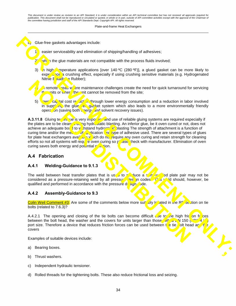
This document is under review as revision to an API Standard; it is under consideration within an API technical committee but has not received all approvals required for publication. This document shall not be reproduced or circulated or quoted, in whole or in part, outside of API committee activities except with the approval of the Chairman of the committee having jurisdiction and staff of the API Standards Dept. Copyright API. All rights reserved.
Plate-and-frame Heat Exchangers
34
b) Glue-free gaskets advantages include:
1) easier serviceability and elimination of shipping/handling of adhesives;
2) when the glue materials are not compatible with the process fluids involved;
3) in high temperature applications [over 140 ºC (280 ºF)], a glued gasket can be more likely to experience a crushing effect, especially if using crushing sensitive materials (e.g. Hydrogenated Nitrile Butadiene Rubber);
4) in remote areas where maintenance challenges create the need for quick turnaround for servicing the units or where the unit cannot be removed from the site;
5) lower capital cost reduction through lower energy consumption and a reduction in labor involved in supplying the glue-free gasket system which also leads to a more environmentally friendly operation (saving both energy and solvent recovery issues).
A.3.11.8 Gluing technique is very important and use of reliable gluing systems are required especially if the plates are to be cleaned using hydrostatic blasting. An inferior glue, be it oven cured or not, does not achieve an adequate bond to withstand hydrostatic blasting The strength of attachment is a function of curing time and/or the method of application and type of adhesive used. There are several types of glues for plate heat exchangers available which do not require any oven curing and retain strength for cleaning efforts so not all systems will require oven curing so please check with manufacturer. Elimination of oven curing saves both energy and potential pollution.
A.4 Fabrication
A.4.1 Welding-Guidance to 9.1.3
The weld between heat transfer plates that is used to produce a semi-welded plate pair may not be considered as a pressure-retaining weld by all pressure design codes. This weld should, however, be qualified and performed in accordance with the pressure design code.
A.4.2 Assembly-Guidance to 9.3
Colin Weil Comment #3: Are some of the comments below more suitably located in the RP section on tie bolts (related to 7.6.3)?
A.4.2.1 The opening and closing of the tie bolts can become difficult due to the high friction forces between the bolt head, the washer and the covers for units larger than those with a DN 150 (NPS 4 in.) port size. Therefore a device that reduces friction forces can be used between the tie bolt head and the covers
Examples of suitable devices include:
a) Bearing boxes.
b) Thrust washers.
c) Independent hydraulic tensioner.
d) Rolled threads for the tightening bolts. These also reduce frictional loss and seizing.
FOR REVIEW & COMMENT ONLY;
NOT FOR DISTRIBUTION

This document is under review as revision to an API Standard; it is under consideration within an API technical committee but has not received all approvals required for publication. This document shall not be reproduced or circulated or quoted, in whole or in part, outside of API committee activities except with the approval of the Chairman of the committee having jurisdiction and staff of the API Standards Dept. Copyright API. All rights reserved.
Plate-and-frame Heat Exchangers
35
A.4.2.2 It is imperative that the manufacturer’s installation procedures, including alignment tolerances and the use of compression bolts, bearing boxes, etc., be strictly followed in order to ensure a leak-free installation. Plate packs with a large number of plates and overall compression are particularly prone to misalignment of the plates, commonly referred to as ‘snaking’, when not properly tightened and can lead to premature leakage.
A.5 Nameplates-Guidance to 10.3.1
Any plate-and-frame heat exchanger that has a lining (e.g. in the nozzles) such as lead, rubber, glass, epoxy, etc. should have warnings printed on the outside of the unit saying “No welding permitted.”
A.6 Protection for Shipment—Guidance to 11.2
A.6.1 If water residues cannot be tolerated then equipment should be dried by one of the following
methods:
a) Blowing dry air or nitrogen, of relative humidity less than 15 % (usually dehumidified), through the heat exchanger and monitoring the outlet air until the relative humidity falls below 30 %.
b) Evacuating the heat exchanger with a vacuum pump to an absolute pressure of between 0.4 kPa (0.06 psi) and 0.5 kPa (0.075 psi).
A.6.2 After draining and drying, internal surfaces can be protected against corrosion by the addition of a desiccant (e.g. silica gel), by the addition of a volatile corrosion inhibitor, or by blanketing with an inert gas such as nitrogen [typically at gauge pressures up to 100 kPa (15 psi)].
FOR REVIEW & COMMENT ONLY;
NOT FOR DISTRIBUTION

This document is under review as revision to an API Standard; it is under consideration within an API technical committee but has not received all approvals required for publication. This document shall not be reproduced or circulated or quoted, in whole or in part, outside of API committee activities except with the approval of the Chairman of the committee having jurisdiction and staff of the API Standards Dept. Copyright API. All rights reserved.
Plate-and-frame Heat Exchangers
36
Annex B (informative)
Plate-and-frame Heat Exchanger Checklist
Completion of the checklist is the responsibility of the purchaser. This checklist is used for listing the purchaser’s specific requirements for which the paragraphs or subsections within this standard include a choice or which designate, by use of a bullet () in the margin, that a decision is required.
Subsection Requirement Item
4.1 Pressure design code. State required code.
4.2 Structural welding code. State required code.
4.4 Applicable local regulations. State local regulations
4.5 Sour service NACE Yes No
4.6 Sour service requirements applied? If yes specify per stream Yes (specify
per stream) No
4.7 Is cyclic design service required? If yes provide detailed
information.
Yes (provide
requirements) No
5.10 Vendor to provide data to allow thermal verification. Yes No
6.2.3 Copies required of applicable welding procedure specifications,
procedure qualifications and weld map.
For
review
For
record
Not
required
6.2.4 Copies required of mechanical design calculations for supports,
lifting and pulling devices.
For
review
For
record
Not
required
6.3.1 Specify the format and quantities for the listed final documents. Provide requirements.
7.2.1 Specify a maximum design temperature and a minimum design
metal temperature (MDMT) for hot and cold sides Complete on datasheet.
7.4 Specify fouling margin Complete on datasheet.
7.5.2 Specify if end plate thicknesses are to be increased to withstand
erosion
Yes No
7.6.6 Specify if shroud required to protect against spray leaks Yes No
7.6.7 Specify if a fire-protection shroud is required and, if so, level of
protection required Complete on datasheet.
7.6.8 Specify if drip tray required Yes No
7.7.2 Specify if studded and/or flanged connections required and also the required facings.
Complete on datasheet.
7.73 Specify the flange gasket facings or the studded port liner facings
Complete on datasheet.
FOR REVIEW & COMMENT ONLY;
NOT FOR DISTRIBUTION
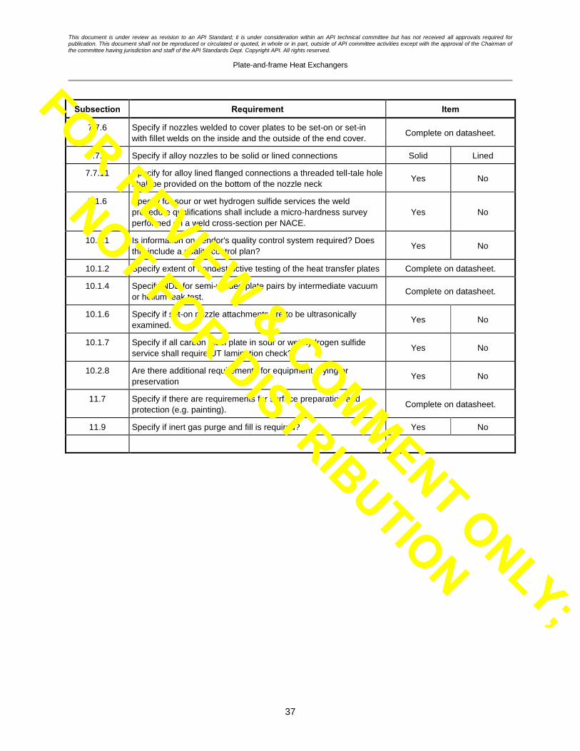
This document is under review as revision to an API Standard; it is under consideration within an API technical committee but has not received all approvals required for publication. This document shall not be reproduced or circulated or quoted, in whole or in part, outside of API committee activities except with the approval of the Chairman of the committee having jurisdiction and staff of the API Standards Dept. Copyright API. All rights reserved.
Plate-and-frame Heat Exchangers
37
Subsection Requirement Item
7.7.6 Specify if nozzles welded to cover plates to be set-on or set-in
with fillet welds on the inside and the outside of the end cover. Complete on datasheet.
7.7.9 Specify if alloy nozzles to be solid or lined connections Solid Lined
7.7.11 Specify for alloy lined flanged connections a threaded tell-tale hole
shall be provided on the bottom of the nozzle neck Yes No
9.1.6 Specify for sour or wet hydrogen sulfide services the weld
procedure qualifications shall include a micro-hardness survey
performed on a weld cross-section per NACE.
Yes No
10.1.1 Is information on vendor's quality control system required? Does
this include a quality control plan? Yes No
10.1.2 Specify extent of nondestructive testing of the heat transfer plates Complete on datasheet.
10.1.4 Specify NDE for semi-welded plate pairs by intermediate vacuum
or helium leak test. Complete on datasheet.
10.1.6 Specify if set-on nozzle attachments are to be ultrasonically
examined. Yes No
10.1.7 Specify if all carbon steel plate in sour or wet hydrogen sulfide
service shall require UT lamination check? Yes No
10.2.8 Are there additional requirements for equipment drying or
preservation Yes No
11.7 Specify if there are requirements for surface preparation and
protection (e.g. painting). Complete on datasheet.
11.9 Specify if inert gas purge and fill is required? Yes No
FOR REVIEW & COMMENT ONLY;
NOT FOR DISTRIBUTION

This document is under review as revision to an API Standard; it is under consideration within an API technical committee but has not received all approvals required for publication. This document shall not be reproduced or circulated or quoted, in whole or in part, outside of API committee activities except with the approval of the Chairman of the committee having jurisdiction and staff of the API Standards Dept. Copyright API. All rights reserved.
Plate-and-frame Heat Exchangers
38
Annex C (informative)
Plate-and-frame Heat Exchanger Datasheets
The following datasheets are provided to assist the designer, vendor and purchaser to specify the data necessary for the design of a plate-and-frame heat exchanger for petroleum and natural gas services.
Completion of the datasheets is a joint responsibility of the purchaser and the vendor. The purchaser (owner or contractor) is responsible for the process data, which define the purchaser’s explicit requirements.
After the exchanger has been fabricated, the vendor should complete the datasheets to make a permanent record that accurately describes the equipment “as-built.”
Editor note: should datasheets be redrafted into EXCEL spreadsheets?
Editor’s note: Will add data sheet page for cyclic service, copying the form and format of the API-660 standard.
FOR REVIEW & COMMENT ONLY;
NOT FOR DISTRIBUTION

This document is under review as revision to an API Standard; it is under consideration within an API technical committee but has not received all approvals required for publication. This document shall not be reproduced or circulated or quoted, in whole or in part, outside of API committee activities except with the approval of the Chairman of the committee having jurisdiction and staff of the API Standards Dept. Copyright API. All rights reserved.
Plate-and-frame Heat Exchangers
39
Company PLATE-AND-FRAME HEAT EXCHANGER DATASHEET (SI UNITS)
PROCESS
Engineering contractor
PO No.: Doc. No.: Page 1 of
Customer: Vendor:
Project: Order/enq. No.:
Location: Model:
Item No.: Serial No.:
Service:
01 CASE HOT SIDE COLD SIDE 02 Fluid
03 Total flow (kg/s)
04 Flow per exchanger (kg/s)
05 Design temperature (max.) (C)
06 Minimum design metal temp. (C)
07 Design pressure [kPa (ga)]
08 Pressure drop allow./calc.- (kPa) / /
09 Port calc. pressure drop inlet/outlet (kPa) / /
09 Wall temperature min./max. (C) / /
10 Fouling margin a (%)
11 OPERATING DATA INLET OUTLET INLET OUTLET
12 Liquid flow (kg/s)
13 Vapor flow (kg/s)
14 Noncondensables flow (kg/s)
15 Operating temperature (C)
16 Operating pressure [kPa (ga)]
17 LIQUID PROPERTIES
18 Density (kg/m3)
19 Specific heat capacity (kJ/kg·K)
20 Dynamic viscosity (mPa·s)
21 Thermal conductivity (W/m·K)
22 Surface tension (N/m)
23 VAPOR PROPERTIES
24 Density (kg/m3)
25 Specific heat capacity (kJ/kg·K)
26 Dynamic viscosity (mPa·s)
27 Thermal conductivity (W/m·K)
28 Relative molecular mass (kg/kmol)
29 Relative molecular mass,
noncondensables
(kg/kmol)
30 Dew point/bubble point (C)
31 Solids maximum size (mm)
32 Solids concentration (% volume)
33 Latent heat (kJ/kg)
34 Critical pressure [kPa (abs)]
35 Critical temperature (C)
36
37 Total heat exchanged (kW)
38 U a (W/m2·K) Clean condition: Service:
39 LMTD (C) /
40 Heat transfer area (m2)
41 Stream heat transfer coefficient (W/m2·K) a Fouling margin = [(Uclean /Uservice) – 1] 100 % where U = Overall heat transfer coefficient (thermal transmittance).
Rev. No. Revision Date Prepared by Reviewed by
FOR REVIEW & COMMENT ONLY;
NOT FOR DISTRIBUTION
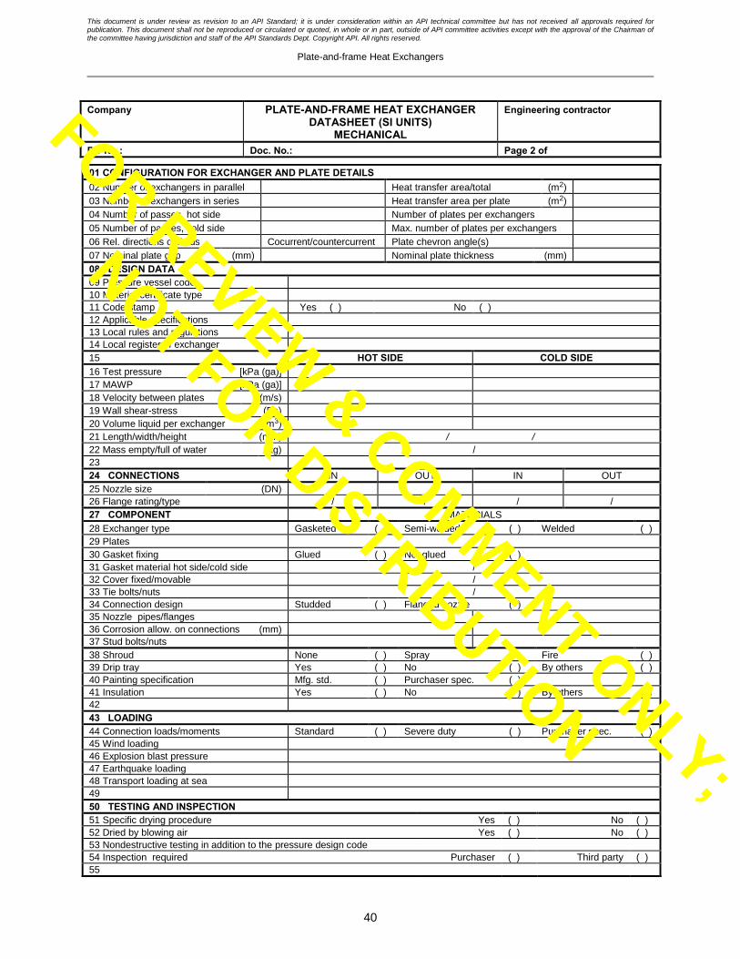
This document is under review as revision to an API Standard; it is under consideration within an API technical committee but has not received all approvals required for publication. This document shall not be reproduced or circulated or quoted, in whole or in part, outside of API committee activities except with the approval of the Chairman of the committee having jurisdiction and staff of the API Standards Dept. Copyright API. All rights reserved.
Plate-and-frame Heat Exchangers
40
Company PLATE-AND-FRAME HEAT EXCHANGER DATASHEET (SI UNITS)
MECHANICAL
Engineering contractor
PO No.: Doc. No.: Page 2 of
01 CONFIGURATION FOR EXCHANGER AND PLATE DETAILS 02 Number of exchangers in parallel Heat transfer area/total (m2)
03 Number of exchangers in series Heat transfer area per plate (m2)
04 Number of passes, hot side Number of plates per exchangers
05 Number of passes, cold side Max. number of plates per exchangers
06 Rel. directions of fluids Cocurrent/countercurrent Plate chevron angle(s)
07 Nominal plate gap (mm) Nominal plate thickness (mm)
08 DESIGN DATA 09 Pressure vessel code
10 Material certificate type
11 Code stamp Yes ( ) No ( )
12 Applicable specifications
13 Local rules and regulations
14 Local register of exchanger
15 HOT SIDE COLD SIDE 16 Test pressure [kPa (ga)]
17 MAWP [kPa (ga)]
18 Velocity between plates (m/s)
19 Wall shear-stress (Pa)
20 Volume liquid per exchanger (m3)
21 Length/width/height (mm) / /
22 Mass empty/full of water (kg) /
23
24 CONNECTIONS IN OUT IN OUT
25 Nozzle size (DN)
26 Flange rating/type / / / /
27 COMPONENT MATERIALS
28 Exchanger type Gasketed ( ) Semi-welded ( ) Welded ( )
29 Plates
30 Gasket fixing Glued ( ) Not glued ( )
31 Gasket material hot side/cold side /
32 Cover fixed/movable /
33 Tie bolts/nuts /
34 Connection design Studded ( ) Flanged nozzle ( )
35 Nozzle pipes/flanges
36 Corrosion allow. on connections (mm)
37 Stud bolts/nuts
38 Shroud None ( ) Spray ( ) Fire ( )
39 Drip tray Yes ( ) No ( ) By others ( )
40 Painting specification Mfg. std. ( ) Purchaser spec. ( )
41 Insulation Yes ( ) No ( ) By others ( )
42
43 LOADING
44 Connection loads/moments Standard ( ) Severe duty ( ) Purchaser spec. ( )
45 Wind loading
46 Explosion blast pressure
47 Earthquake loading
48 Transport loading at sea
49
50 TESTING AND INSPECTION 51 Specific drying procedure Yes ( ) No ( )
52 Dried by blowing air Yes ( ) No ( )
53 Nondestructive testing in addition to the pressure design code
54 Inspection required Purchaser ( ) Third party ( )
55
FOR REVIEW & COMMENT ONLY;
NOT FOR DISTRIBUTION

This document is under review as revision to an API Standard; it is under consideration within an API technical committee but has not received all approvals required for publication. This document shall not be reproduced or circulated or quoted, in whole or in part, outside of API committee activities except with the approval of the Chairman of the committee having jurisdiction and staff of the API Standards Dept. Copyright API. All rights reserved.
Plate-and-frame Heat Exchangers
41
Company PLATE-AND-FRAME HEAT EXCHANGER DATASHEET (SI UNITS)
PROCESS
Engineering contractor
PO No.: Doc. No.: Page 3 of
PHYSICAL PROPERTIES
(INCLUDING WATER IF PRESENT)
Temperature (C)
CASE Pressure [kPa (abs)]
Heat released (kW)
Mass fraction vapor
Mass fraction H2O in liquid
Density (kg/m3)
LIQUID
PHASE
Specific heat capacity (kJ/kg·K)
Dynamic viscosity (mPa·s)
Thermal conductivity (W/m·K)
Surface tension (N/m)
Vapor pressure [kPa (abs)]
Density (kg/m3)
VAPOR
PHASE
Specific heat (kJ/kg·K)
Dynamic viscosity (mPa·s)
Thermal conductivity (W/m·K)
Vapor pressure [kPa (abs)]
Relative molecular
mass
(kg/kmol)
Latent heat (kJ/kg)
Critical pressure [kPa (abs)]
Critical temperature (C)
NOTES:
Rev. No. Revision Date Prepared by Reviewed by
FOR REVIEW & COMMENT ONLY;
NOT FOR DISTRIBUTION

This document is under review as revision to an API Standard; it is under consideration within an API technical committee but has not received all approvals required for publication. This document shall not be reproduced or circulated or quoted, in whole or in part, outside of API committee activities except with the approval of the Chairman of the committee having jurisdiction and staff of the API Standards Dept. Copyright API. All rights reserved.
Plate-and-frame Heat Exchangers
42
Company PLATE-AND-FRAME HEAT EXCHANGER DATASHEET (US CUSTOMARY UNITS)
PROCESS
Engineering contractor
PO No.: Doc. No.: Page 1 of
Customer: Vendor:
Project: Order/enq. No.:
Location: Model:
Item No.: Serial No.:
Service:
01 CASE HOT SIDE COLD SIDE 02 Fluid
03 Total flow (lb/h)
04 Flow per exchanger (lb/h)
05 Design temperature (max.) (F)
06 Minimum design metal temp. (F)
07 Design pressure (psig)
08 Pressure drop allow./calc. (psi) / /
09 Wall temperature min./max. (F) / /
10 Fouling margin a (%)
11 OPERATING DATA INLET OUTLET INLET OUTLET
12 Liquid flow (lb/h)
13 Vapor flow (lb/h)
14 Noncondensables flow (lb/h)
15 Operating temperature (F)
16 Operating pressure (psig)
17 LIQUID PROPERTIES
18 Density (lb/ft3)
19 Specific heat capacity (BTU/lb R)
20 Dynamic viscosity (cP)
21 Thermal conductivity (BTU/ft·h·R)
22 Surface tension (Dynes/cm)
23 VAPOR PROPERTIES
24 Density (lb/ft3)
25 Specific heat capacity (BTU/lb·R)
26 Dynamic viscosity (cP)
27 Thermal conductivity (BTU/ft·h·R)
28 Relative molecular mass (lb/lb·mol)
29 Relative molecular mass,
noncondensables
(lb/lb·mol)
30 Dew point/bubble point (F)
31 Solids maximum size (in.)
32 Solids concentration (% volume)
33 Latent heat (BTU/lb)
34 Critical pressure (psia)
35 Critical temperature (F)
36
37 Total heat exchanged (BTU/h)
38 Ua (BTU/h·ft2·R) Clean condition: Service:
39 LMTD (F) /
40 Heat transfer area (ft2)
41 Stream heat transfer
coefficient
(BTU/h·ft2·R)
a Fouling margin = [(Uclean/Uservice)– 1] 100 % where U = Overall heat transfer coefficient (thermal transmittance).
Rev. No. Revision Date Prepared by Reviewed by
FOR REVIEW & COMMENT ONLY;
NOT FOR DISTRIBUTION

This document is under review as revision to an API Standard; it is under consideration within an API technical committee but has not received all approvals required for publication. This document shall not be reproduced or circulated or quoted, in whole or in part, outside of API committee activities except with the approval of the Chairman of the committee having jurisdiction and staff of the API Standards Dept. Copyright API. All rights reserved.
Plate-and-frame Heat Exchangers
43
Company PLATE-AND-FRAME HEAT EXCHANGER DATASHEET (US CUSTOMARY UNITS)
MECHANICAL
Engineering contractor
PO No.: Doc. No.: Page 2 of
01 CONFIGURATION FOR EXCHANGER AND PLATE DETAILS 02 Number of exchangers in parallel Heat transfer area/total (ft2)
03 Number of exchangers in series Heat transfer area per plate (ft2)
04 Number of passes, hot side Number of plates per exchanger
05 Number of passes, cold side Max. number of plates per exchanger
06 Rel. directions of fluids Cocurrent/countercurrent Plate chevron angle(s)
07 Nominal plate gap (in.) Nominal plate thickness (in.)
08 DESIGN DATA 09 Pressure vessel code
10 Material certificate type
11 Code stamp Yes ( ) No ( )
12 Applicable specifications
13 Local rules and regulations
14 Local register of exchanger
15 HOT SIDE COLD SIDE 16 Test pressure (psig)
17 MAWP (psig)
18 Velocity between plates (ft/s)
19 Wall shear-stress (psi)
20 Volume liquid per exchanger (ft3)
21 Length/width/height (in.)
22 Mass empty/full of water (lb) /
23
24 CONNECTIONS IN OUT IN OUT
25 Nozzle size (NPS)
26 Flange rating/type / / / /
27 COMPONENT MATERIALS
28 Exchanger type Gasketed ( ) Semi-welded ( ) Welded ( )
29 Plates
30 Gasket fixing Glued ( ) Not glued ( )
31 Gaskets hot side/cold side /
32 Cover fixed/movable /
33 Tie bolts/nuts /
34 Connection design Studded ( ) Flanged nozzle ( )
35 Nozzle pipes/flanges
36 Corrosion allow. on connections (in.)
37 Stud bolts/nuts
38 Shroud None ( ) Spray ( ) Fire ( )
39 Drip tray Yes ( ) No ( ) By others ( )
40 Painting specification Mfg. std. ( ) Purchaser spec. ( )
41 Insulation Yes ( ) No ( ) By others ( )
42
43 LOADING
44 Connection loads/moments Standard ( ) Severe duty ( ) Purchaser spec. ( )
45 Wind loading
46 Explosion blast pressure
47 Earthquake loading
48 Transport loading at sea
49
50 TESTING AND INSPECTION 51 Specific drying procedure Yes ( ) No ( )
52 Dried by blowing air Yes ( ) No ( )
53 Nondestructive testing in addition to the pressure design code
54 Inspection required Purchaser ( ) Third party ( )
55
FOR REVIEW & COMMENT ONLY;
NOT FOR DISTRIBUTION

This document is under review as revision to an API Standard; it is under consideration within an API technical committee but has not received all approvals required for publication. This document shall not be reproduced or circulated or quoted, in whole or in part, outside of API committee activities except with the approval of the Chairman of the committee having jurisdiction and staff of the API Standards Dept. Copyright API. All rights reserved.
Plate-and-frame Heat Exchangers
44
Company PLATE-AND-FRAME HEAT EXCHANGER DATASHEET (US CUSTOMARY UNITS)
PROCESS
Engineering contractor
PO No.: Doc. No.: Page 3 of
PHYSICAL PROPERTIES
(INCLUDING WATER IF PRESENT)
CASE Temperature (F)
Pressure (psia)
Heat released (BTU/h)
Mass fraction vapor
Mass fraction H2O in liquid
Density (lb/ft3)
LIQUID
PHASE
Specific heat
capacity
(BTU/lb·R)
Viscosity (cP)
Thermal
conductivity
(BTU/h·ft·R)
Surface tension (dyn/cm)
Vapor pressure (psia)
Density (lb/ft3)
VAPOR
PHASE
Specific heat
capacity
(BTU/lb·R)
Viscosity (cP)
Thermal
conductivity
(BTU/h·ft·R)
Vapor pressure (psia)
Relative molecular
mass
(lb/lb·mol)
Latent heat (BTU/lb)
Critical pressure (psia)
Critical temperature (F)
NOTES:
Rev. No. Revision Date Prepared by Reviewed by
FOR REVIEW & COMMENT ONLY;
NOT FOR DISTRIBUTION

FOR REVIEW & COMMENT ONLY;
NOT FOR DISTRIBUTION

This document is under review as revision to an API Standard; it is under consideration within an API technical committee but has not received all approvals required for
publication. This document shall not be reproduced or circulated or quoted, in whole or in part, outside of API committee activities except with the approval of the Chairman of
the committee having jurisdiction and staff of the API Standards Dept. Copyright API. All rights reserved.
Plate-and-frame Heat Exchangers
46
Bibliography
[1] EN 13445 2 (all parts), Unfired pressure vessels
[2] ASME Boiler and Pressure Vessel Code 3 , (BPVC) Section VIII: Rules for Construction of Pressure Vessels
[3] ASME Boiler and Pressure Vessel Code, (BPVC) Section VIII: Rules for Construction of Pressure Vessels; Division 2: Alternative Rules
[4] ASME B16.5,
2 Comité Européen de Normalisation, 36, rue de Stassart, B-1050 Brussels, Belgium, www.cen.eu.
3 ASME International, 3 Park Avenue, New York, New York 10016-5990, www.asme.org.
FOR REVIEW & COMMENT ONLY;
NOT FOR DISTRIBUTION