platform for enhanced light graphene interaction length
TRANSCRIPT
Platform for enhanced light–grapheneinteraction length and miniaturizing fiberstereo devicesJUN-LONG KOU,1,† JIN-HUI CHEN,1,† YE CHEN,1 FEI XU,1,* AND YAN-QING LU1,2
1National Laboratory of Solid State Microstructures and College of Engineering and Applied Sciences, Nanjing University, Nanjing 210093, China
2e-mail: [email protected]
*Corresponding author: [email protected]
Received 30 July 2014; revised 23 September 2014; accepted 1 October 2014 (Doc. ID 219967); published 31 October 2014
Sufficient light–matter interactions are important forwaveguide-coupled graphene optoelectronic devices.Subwavelength-diameter microfibers (MFs) with astrong evanescent field are attractive for graphene inte-gration in fiber optics system, which can be realized bycovering or wrapping a graphene sheet on a straight andthin MF. However, it is challenging to handle such athin MF and graphene for sufficient length and strengthof interaction. Using an MF-based lab-on-a-rod tech-nique, we present a platform for ultralong light–graphene interaction and design graphene-integratedhelical MF devices. Using this approach, we experimen-tally demonstrate polarization manipulation by wrap-ping an MF on a rod pretreated with a graphenesheet. The device can operate as not only a broadbandpolarizer but also a high-Q single-polarization resonatorby tuning the geometry of MF coils. By specializing therod surface and coil geometry, we believe the platformcould contribute to advancing the research for moregraphene–MF-integrated devices including modulatorsand photodetectors. © 2014 Optical Society of America
OCIS codes: (060.2310) Fiber optics; (060.2340) Fiber optics compo-
nents; (060.2420) Fibers, polarization-maintaining; (060.2370) Fiber
optics sensors.
http://dx.doi.org/10.1364/OPTICA.1.000307
Since the discovery of graphene, the optical properties of two-dimensional Dirac fermions have been studied extensively[1,2]. By utilizing properties such as linear optical absorption,saturable absorption, and the tunability of chemical potential
through doping or electrical gating, various broadband appli-cations [3], such as modulators [4,5], photon detectors [6,7],polarizers [8], and mode-lock lasers [9,10], have been realized.Most practical applications require graphene to be integratedwith existing photonic technology to attain sufficient interac-tion lengths between the graphene and optical field because theinteraction length is limited by the thickness of graphene fornormal incident light in conventional free-space optical sys-tems. This integration can be readily achieved by transferringand laminating graphene on top of waveguides [11]. In fiberoptics systems, side-polishing or flame-drawing techniques areemployed to obtain D-shaped fibers or microfibers (MFs)[8,12], which provide an accessible evanescent field. In par-ticular, MFs with a strong evanescent fields have attracted in-creasing attention. Hybrid graphene–microfiber (GMF)devices can be fabricated by covering or wrapping a graphenesheet on a straight, thin MF [13]. However, it is still challeng-ing to handle such a thin MF–graphene structure for sufficientlengths and strengths of interaction. Here, relying on theMF-based lab-on-a-rod technique, we present an alternativeapproach to integrate GMF devices by wrapping an MF ona graphene-coated rod, schematically shown in Fig. 1. Imple-mentation of the approach is simple and efficient because theprocess only involves coating a small piece of graphene onto arod. While maintaining a strong evanescent field, the GMFinteraction length can, in theory, be increased arbitrarily witha helical structure of multicoils. Another unique advantage isthe possible formation of resonators with strong coupling be-tween adjacent coils through adjustment of the spring pitches.The approach provides new opportunities for elaboration ofstereo GMF-integrated devices. Various all-fiber graphene de-vices are expected to be developed by employing such a flexibleplatform; such devices include electrical or optical modulators,photon detectors, and polarization controlling components(PCCs). In this work, we show the platform’s applicationto broadband polarization manipulation.
Letter Vol. 1, No. 5 / November 2014 / Optica 307
2334-2536/14/050307-04$15/0$15.00 © 2014 Optical Society of America
Polarization behavior has a profound impact on the perfor-mance of optical-fiber devices and systems [8,14]. To imple-ment optical-fiber devices in practical applications, controland manipulation of the polarization state of light is highlydesirable. All-fiber PCCs are more attractive because manipu-lating free-space PCCs during collimating, aligning, and (re)focusing is time consuming and labor intensive. However,conventional-fiber PCCs have to be carefully kept as straightas possible to prevent additional birefringence. This requiressplicing or connecting and careful assembly as well as align-ment to achieve the desired optical performance. It is alsodifficult to coil conventional-fiber PCCs well and form asingle-polarization microresonator. Moreover, miniaturizationof devices is important for large scale. One of theapparent advantages of our device is the compact footprintattributed to its coil configuration, which employs the stereostructure. Recently, we demonstrated a broadband single-polarization resonator based on a silver-film configuration[15]. Here, we take one step forward by mating MF with a2D graphene sheet, which interacts strongly with an in-planelightwave. Meanwhile, due to the unique dispersion propertyof graphene, the stereo device in this Letter exhibits intriguingresults that are not likely to be expected in the silver-film de-vices due to the tremendous difference in the fabricationmethod and polarization behavior. In particular, the extinctionratio (ER) is intensity dependent because of the special absorp-tion properties of graphene.
In this study, a stereo GMF-integrated platform and the so-called wrap-on-a-rod technique are used to enable the integra-tion and miniaturization of multifunctional GMF PCCs. Thekey to the technique lies in the graphene specialization of therod’s surface, which interacts strongly with the evanescent fieldpropagating outside the MF. By adjusting the neighboringdistance of the coils, a compact in-line polarizer or high-Qsingle-polarization resonator can be obtained. This stereographene-integrated resonator with unique 3D geometry elim-inates the requirement of separate couplers, which makes theresonator especially attractive for special applications, such as
gyroscopes and current sensors. This preliminary work couldlay the foundation for future lab-on-a-rod GMF devices.
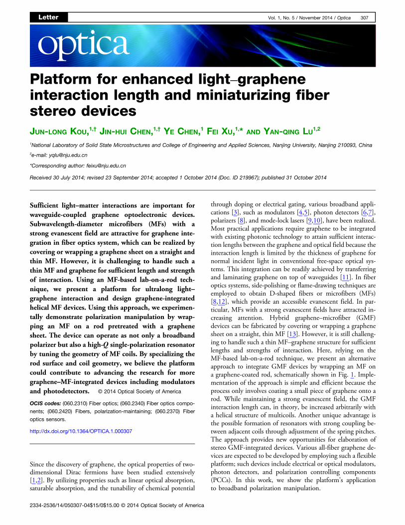
Figure 1 is a schematic of the GMF in-line polarizer (GMF-IP) or GMF single-polarization resonator (GMF-SR). Theonly difference between these lies in the distance (d, as labeledin Fig. 1) between neighboring coils. To prevent the loss in-duced by the relatively high-index rod (polymethyl methacry-late or PMMA, diameter is ∼2 mm), a thin layer of low-indexTeflon (Teflon AF 601S1-100-6, DuPont, tens of microme-ters in thickness, index is ∼1.31) was initially dip-coated onthe rod surface. A monolayer graphene sheet (ACS Material)grown by chemical vapor deposition (CVD) was then mechan-ically transferred onto the surface of the Teflon coating. Thelength of the graphene sheet was carefully tailored so that itcould be wrapped around the rod such that the opposite edgesmeet at the same line and do not overlap. Finally, an MF(∼3 μm in diameter) was tightly wrapped on the graphenesheet supported by the rod.
The broken symmetry with respect to the local y � 0 planecauses the nondegeneracy of the two fundamental modes inthis hybrid structure. Here, we define the mode with the dom-inant electric field component in the x direction (Ex) as an evenmode because Ex is symmetric to the mirror plane (x � 0plane, perpendicular to the local graphene plane). The othermode, mainly polarized in the y direction, is considered anodd mode. Because of the large evanescent field of the MF,a fraction of the light field penetrates the ambient environ-ment, including the graphene sheet. For intrinsic or slightlydoped graphene �jμj < hω∕4π�, an inter band transitiondominates the high-frequency dynamic conductivity withinthe range from visible to infrared (IR) [3]. Thus, the existenceof the graphene sheet contributes to the losses in differentmodes, causing the device to exhibit a contrasting ER.
We first studied the optical transmission properties of theGMF-IP, in which a distance (tens of micrometers) was main-tained between different coils of the MF to prevent mutualcoupling [16]. The ER was experimentally measured in thenear IR (NIR) range, from 1200 to 1650 nm. We chose thisrange because many high-order modes appear below 1200 nm,and the broadband light source (SuperK Versa, NKT) termi-nates near 1650 nm. By incorporating a linear polarizerfollowed by a half-wave plate between the source and thedevice, the polarization state of the incident light can be con-trolled by rotating the plate. As clearly shown in Fig. 2, maxi-mum transmission is achieved at θ � 90°, in which case theodd mode is excited, whereas minimum transmission occurs atθ � 0°. The device with a one-coil structure (meaning that theMF is in contact with the graphene sheet over ∼6.3 mm) givesan ER of ∼5 dB at 1310 nm and ∼8 dB at 1550 nm. As theoperating wavelength increases, the ER increases; this phe-nomenon will be explained below. To further increase ER,a longer MF was employed to form a two-coil [Fig. 3(a)] ormulticoil structure. As expected, ER nearly doubled whenthe contact between the MF and graphene was lengthenedto ∼12.6 mm. We note a dip in the output spectrum around1380 nm, which is possibly caused by the absorption loss ofthe extra OH groups released during hydrogen flame heating[17]. A control experiment was also performed on an MF
Fig. 1. Schematic of a graphene-based MF in-line polarizer with atwo-coil structure. The rod’s diameter is hundreds of times larger thanthat of the MF. The GMF interaction length can be extended nearlyindefinitely on a small piece of graphene by increasing the number ofhelical turns. R, radius of the rod; r, radius of the MF; θ, angle betweenthe incident polarization direction and the x axis. Two sets of local co-ordinates are shown, one at the input and the other in the middle. Thedominant component of the electric field for the even and odd modes ispolarized in the x and y directions, respectively.
Letter Vol. 1, No. 5 / November 2014 / Optica 308

wrapped on a rod pretreated only with Teflon coating, withouta graphene sheet. The results show no evident polarizing effect.
When adjacent coils of the MF are sufficiently close, theyform a high-Q resonator [18]. We carefully wrapped two MFcoils onto the graphene-coated rodwith the help of amicroscopeto ensure that the coils were close to each other, as illustratedin Fig. 3(b). The transmission spectra of GMF-SR for twoorthogonal modes (even and odd) are shown in Fig. 4. Theyclearly differ in output power because themodes suffer from dif-ferent propagation losses. From Fig. 4(b), we find that aroundthe telecommunicationwavelength of 1550 nm, the free spectralrange (FSR) and full width at half-maximum (FWHM) are ap-proximately 0.23 nm and 0.08 nm, respectively, indicating thatthe Q-factor approaches 2 × 10⁴. The difference in outputpower between the dips of the two modes is ∼11 dB, fromwhich we conclude that the device could work as a single-polari-zation resonator. In this manner, mutual coupling between dif-ferent modes could be well suppressed, which is especiallyattractive for certain specialized applications such as gyroscopesand current sensors. This functionality cannot be realized in aone-dimensional fiber system. The ER could be further im-proved if the MFs are drawn into even thinner structures.
To confirm the experimental results, we theoretically ana-lyzed the mode losses. In our simulations, the ultrathin gra-phene sheet was treated as a 1-nm-thick dielectric layer.The relative permittivity of graphene was obtained using the
relation ε � 1� iσ∕ε0ωd, where σ is the dynamical conduc-tivity determined from the Kubo formula, ε0 is the permittivityof vacuum, and ω is the operating frequency [3]. The theo-retical ER was obtained via �αeven − αodd�LMF, with αi(i � even or odd) being the attenuation constant of each modeand LMF being the length of the MF in contact with the gra-phene sheet. αi can be readily obtained from the imaginarypart of the propagation constants solved by the finite elementmethod. Figure 5(a) displays the results of ER versus operatingwavelength for GMF-IP. The trend of the experimental results
-28
-24
-20
-160
30
60
90
120
150180
210
240
270
300
330
-28
-24
-20
-16
Out
put
pow
er (
dB)
1550nm 1310nm
(a)
-50
-40
-30
-200
30
60
90
120
150180
210
240
270
300
330
-50
-40
-30
-20
Out
put
pow
er (
dB)
1550nm 1310nm
(b)
1200 1300 1400 1500 1600-33
-30
-27
-24
-21
-18
-15
Out
put
pow
er (
dB)
wavelength (nm)
even mode odd mode
(c)
1200 1300 1400 1500 1600
-50
-45
-40
-35
-30
-25
Out
put
pow
er (
dB)
wavelength (nm)
even mode odd mode
(d)
Fig. 2. Output power as a function of θ at 1310 and 1550 nm for (a) aone-coil structure and (b) a two-coil structure. The data were recorded byrotating the half-wave plate in 7.5° increments. Wavelength-dependentoutput power for (c) one-coil structure and (d) a two-coil structure. Theblack (red) line represents the data at θ � 0° (90°).
Fig. 3. (a) Optical microscope image of a two-coil MF wrapped on arod pretreated with Teflon coating and a graphene sheet. (b) Scanningelectron microscope image of two coils close to each other.
1530 1540 1550 1560
-40
-35
-30
-25
-20
Out
put
pow
er (
dB)
Wavelength (nm)
even mode odd mode
(a)
1549 1550 1551
-40
-35
-30
-25
-20
Out
put
pow
er (
dB)
wavelength (nm)
even mode odd mode
(b)
Fig. 4. (a) Transmission spectrum of the graphene-based resonator fortwo orthogonal modes. (b) Detailed expansion of the spectrum at around1550 nm.
1200 1300 1400 1500 1600
9
12
15
18
21
24
Ext
inct
ion
Rat
io (
dB)
Wavelength (nm)
Experimental Theoretical
(a)
1200 1300 1400 1500 1600 17000
5
10
15
20
25
30
35
η grap
hene
(×1
0-6)
Wavelength (nm)
even mode odd mode
(b)
Fig. 5. (a) Experimental and theoretical results of ER for GMF-IP.(b) Calculated time-averaged power flow ratio for power carried bythe graphene sheet as a function of wavelength.
Letter Vol. 1, No. 5 / November 2014 / Optica 309

follows that of the theory at high frequencies. However, mis-match appears at wavelengths below 1300 nm. This mismatchcan be attributed to the contribution of high-order modes andthe nonuniformity of MFs, both of which are neglected in ourcalculation. Moreover, ER increases with the wavelength,which is also observed in Ref. [8]. Another calculation was per-formed to obtain the time-averaged power flow ratio in thegraphene layer (ηgraphene), shown in Fig. 5(b). For the evenmode, we clearly see that as the wavelength increases,ηgraphene increases. For the odd mode, however, ηgraphene re-mains constant over the 450 nm wavelength range. Becausethe graphene sheet is a lossy medium, more energy will beattenuated when ηgraphene is high. This explains the increasingtendency of ER in Fig. 5(a).
For GMF-SR, the transmission spectrum of each mode canbe obtained (Fig. 6) through the following equation, whichincorporates loss [19]:
T i�e−4πRβ2;i�sin2�2πRκi�−2sin�2πRβ1;i�sin�2πRκi�e−2πRβ2;ie4πRβ2;i�sin2�2πRκi�−2sin�2πRβ1;i�sin�2πRκi�e2πRβ2;i
;
(1)
where β1;i and β2;i are the real and imaginary parts of the com-plex propagation constant, respectively, R is the radius of therod, and κi is the coupling coefficient for the correspondingmode. Here, a semi-theoretical method was employed. β1;iand β2;i were calculated by the finite element method, while2πRκeven � 0.15 and 2πRκodd � 1.0 were chosen to fit the ex-perimental results. These values of κi were selected on the basisof two aspects. On one hand, κi is dependent on polarization.On the other hand, κi is difficult to predict because it is sensitiveto both the distance between neighboring coils and the MF ra-dius. In the fitting, the insertion loss (Ii) of different modesresulting from coupling, connection, scattering, and bendingwas not included. The calculated FSR was ∼0.25 nm, whichis close to the experimentally observed value (∼0.23 nm). Theeven mode exhibits a lower transmission than the odd modebecause, in the even mode, the electric field, mainly polarizedin the x direction, interacts more with the graphene sheet.
In conclusion, we have presented a new platform for minia-turizing GMF-integrated stereo devices. The unique geometrypractically enables multiple light–graphene interaction lengthson a small piece of graphene, and the realization of a number ofGMF broadband devices, including microresonators. As an
example, we demonstrated the in-line manipulation of polari-zation with GMF-integrated devices. First, a GMF-IP wasshown to achieve an ER of 8 dB/coil. By employing a two-coilstructure, an ER as high as ∼16 dB was obtained over a450 nm bandwidth in the telecommunication wavelengthrange. Second, we took a step toward the realization of ahigh-Q graphene-based SR with excellent suppression of polari-zation noise and used a semi-empirical model to explain theresults. Similar results are expected with the use of RGB fibersin the visible range and endless single-mode photonic crystalfibers over the visible to NIR range. Moreover, our design alsogives insights into the realization of future lab-on-a-rod devicesand provides the general recipe for optoelectrical applicationson the integration of MFs with the fast rising 2D materials,including graphene and transition metal dichalcogenide.
FUNDING INFORMATION
National 973 program (2011CBA00205, 2012CB921803);National Science Fund for Distinguished Young Scholars(61225026); National Science Fund for Excellent YoungScientists Fund (61322503).
ACKNOWLEDGMENT
We thank Prof. Xiaoshun Jiang and Xuejing Zhang for helpwith numerical simulations.†These authors contributed equally to this work.
REFERENCES
1. F. Bonaccorso, Z. Sun, T. Hasan, and A. C. Ferrari, Nat. Photonics4, 611 (2010).
2. P. Avouris, Nano Lett. 10, 4285 (2010).3. Q. Bao and K. P. Loh, ACS Nano 6, 3677 (2012).4. M. Liu, X. Yin, E. Ulin-Avila, B. Geng, T. Zentgraf, L. Ju, F. Wang, and
X. Zhang, Nature 474, 64 (2011).5. M. Liu, X. Yin, and X. Zhang, Nano Lett. 12, 1482 (2012).6. F. Xia, T. Mueller, Y.-M. Lin, A. Valdes-Garcia, and P. Avouris, Nat.
Nanotechnol. 4, 839 (2009).7. T. Mueller, F. Xia, and P. Avouris, Nat. Photonics 4, 297 (2010).8. Q. Bao, H. Zhang, B. Wang, Z. Ni, C. H. Y. X. Lim, Y. Wang, D. Y.
Tang, and K. P. Loh, Nat. Photonics 5, 411 (2011).9. H. Zhang, Q. Bao, D. Tang, L. Zhao, and K. Loh, Appl. Phys. Lett. 95,
141103 (2009).10. Z. Sun, T. Hasan, F. Torrisi, D. Popa, G. Privitera, F. Wang, F.
Bonaccorso, D. M. Basko, and A. C. Ferrari, ACSNano 4, 803 (2010).11. S. J. Koester and L. Mo, IEEE J. Sel. Top. Quantum Electron. 20, 84
(2014).12. W. Li, B. Chen, C. Meng, W. Fang, Y. Xiao, X. Li, Z. Hu, Y. Xu, L.
Tong, H. Wang, W. Liu, J. Bao, and Y. R. Shen, Nano Lett. 14, 955(2014).
13. Z.-B. Liu, M. Feng, W.-S. Jiang, W. Xin, P. Wang, Q.-W. Sheng,Y.-G. Liu, D. N. Wang, W.-Y. Zhou, and J.-G. Tian, Laser Phys. Lett.10, 065901 (2013).
14. V. I. Kopp, V. M. Churikov, J. Singer, N. Chao, D. Neugroschl, andA. Z. Genack, Science 305, 74 (2004).
15. J.-H. Chen, Y. Chen, W. Luo, J.-L. Kou, F. Xu, and Y.-Q. Lu, Opt.Express 22, 17890 (2014).
16. J.-L. Kou, Y. Chen, F. Xu, and Y.-Q. Lu, Opt. Express 20, 28431(2012).
17. H. Osanai, T. Shioda, T. Moriyama, S. Araki, M. Horiguchi, T. Izawa,and H. Takata, Electron. Lett. 12, 549 (1976).
18. G. Brambilla, J. Opt. 12, 043001 (2010).19. M. Sumetsky, Opt. Express 12, 2303 (2004).
1549 1550 1551
-30
-25
-20
-15
-10
-5
Ti (
dB)
wavelength (nm)
even mode odd mode
Fig. 6. Calculated transmission of the GMF-SR based on a semi-theoretical method. Insertion loss resulting from coupling, connection,scattering, and bending was not taken into account here.
Letter Vol. 1, No. 5 / November 2014 / Optica 310