plc & scada report 5
TRANSCRIPT

ABSTRACT Industrial training is must for the every student perusing professional degree because the ultimate goal of every student is to get the information the industrial training helps us to get an idea of the things. We should know in order to get a job i.e. I have a good professional career. Industrial training teaches us lots of thing s. it helps us to know the kind of environment we would be getting in the industry and help us to get with the kind of environment. The totality the industrial teaches us industrial ethics. Some advance technical how and help us to acquire with industrial working style. Supervisory control and data acquisition (SCADA) allows a utility operator to monitor and control processes that are distributed among various remote sites. SCADA is a system for gathering real time data, controlling processes, and monitoring equipment from remote locations. As more companies are implementing an open SCADA architecture through the Internet to monitor critical infrastructure components such as power plants, oil and gas pipelines, chemical refineries, flood control dams, and waste and water systems, vital systems are becoming increasingly open to attack. This report provides an overview of SCADA, outlines several vulnerabilities of SCADA systems, presents data on known and possible threats, and provides particular remediation strategies for protecting these systems. PLCs are used in many different industries and machines such as packaging and semiconductor machines. Programs to control machine operation are typically stored in battery-backed or non-volatile memory. A programmable logic controller (PLC) or programmable controller is a digital computer used for automation of electromechanical processes, such as control of machinery on factory assembly lines, amusement rides, or lighting fixtures. PLCs are used in many industries and machines. Unlike general-purpose computers, the PLC is designed for multiple inputs and output arrangements, extended temperature ranges, immunity to electrical noise, and resistance to vibration and impact.

CONTENT
CHAPTER 1- AUTOMATION………………………………………
CHAPTER 2- SUPERVISORY CONTROL AND DATA ACQUISITION……
CHAPTER 3- PROGRAMABLE LOGIC CONTROLLER……………….
CHAPTER 4- LADDER LOGIC EXAMPLES…………………………
CHAPTER 5- PANEL DESIGNING/WIRING &INSTALLATION ……….
CHAPTER 6- PROJECT WORK………….
CONTAIN OF CHAPTER
DEFINATION OF automation
Type of automation
Block diagram
Benefits
Application
Maintenance
Programming
Controlling
DEFINATION of AUTOMATION
AUTOMATION
(DRIVED FROM) [GREEK WORD OF “AUTO (SELF) +”MOTUS” (MOVING) ]
“AUTOMATION AS OPPOSED TO HUMAN OPERATION OR CONTROL OF PROCESS ,EQUIPMENT OR A SYSTEM .”
-The diffination of automation is the use of machines and technlogy to make processes run on their without manpower.ex- work by conver belt&servo motor
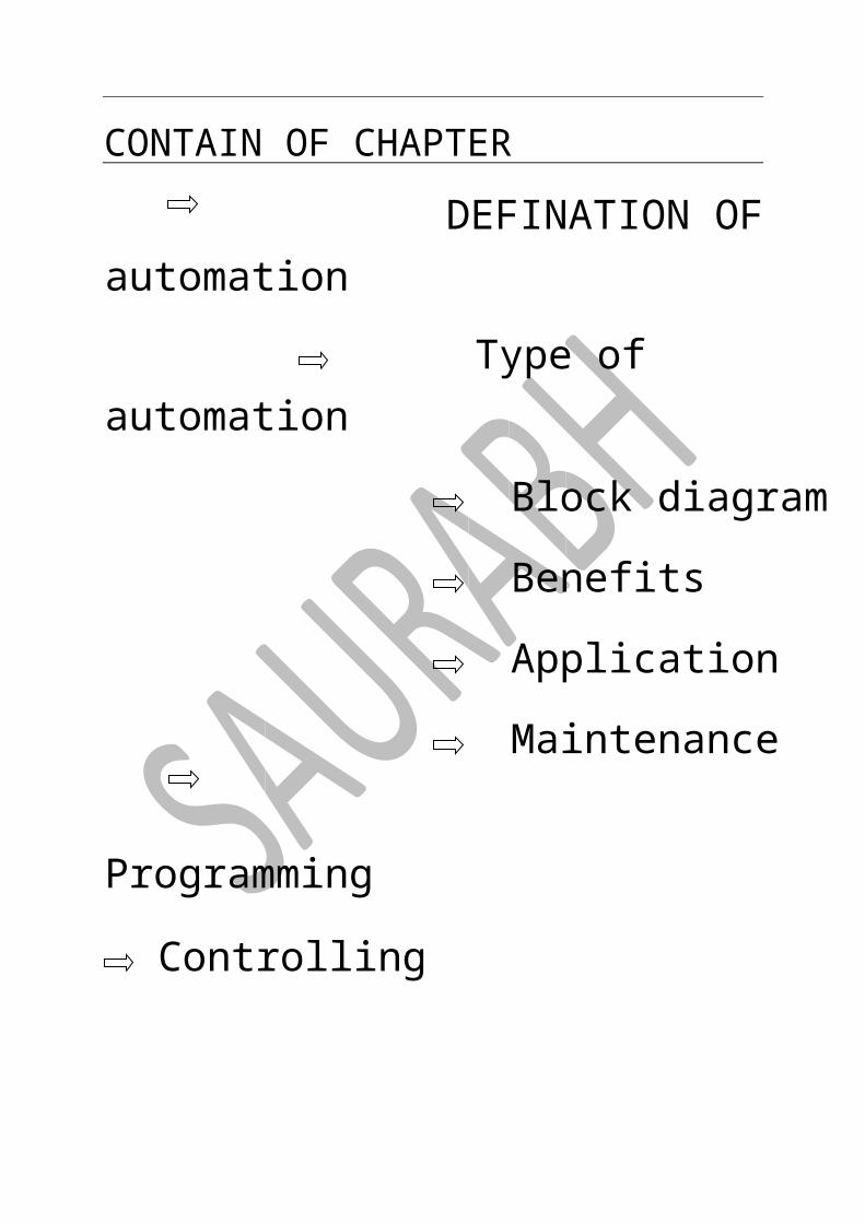
TYPE OF AUTOMATION & APPLICATIONS

Mainly automation are following types
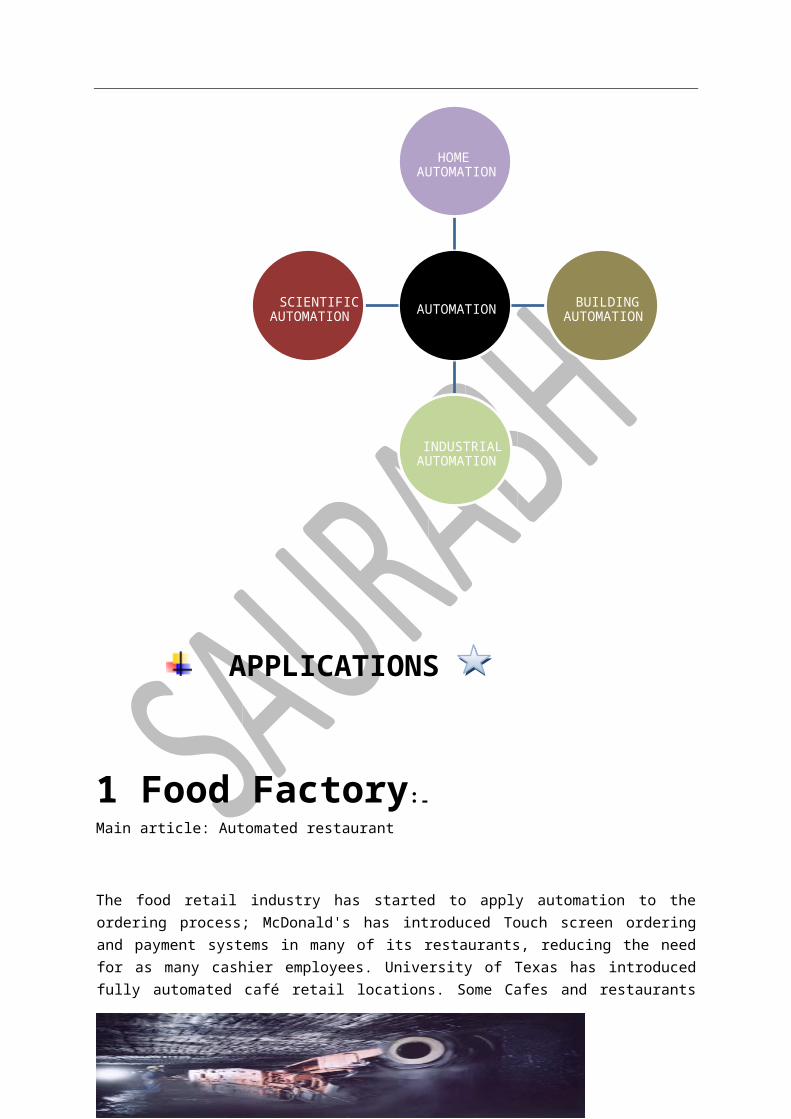
APPLICATIONS
1 Food Factory:- Main article: Automated restaurant
The food retail industry has started to apply automation to the ordering process; McDonald's has introduced Touch screen ordering and payment systems in many of its restaurants, reducing the
AUTOMATIONSCIENTIFIC
AUTOMATION INDUSTRIAL
AUTOMATIONBUILDING
AUTOMATIONHOME
AUTOMATION

need for as many cashier employees. University of Texas has introduced fully automated café retail locations. Some Cafes and restaurants have utilized mobile and tablet "apps" to make the ordering process more efficient by customersOrdering and paying on their device. Some restaurants have automated food delivery to customer’s tables using A Conveyor belt system. The use of robots is sometimes employed to replace waiting staff.
2 Automated Mining:-
Main article: Automated mining
Involves the removal of human labor from themining process. The mining industry is currently in the
transition towards Automation. Currently it can still require a large amount of human capital, particularly in the third world where labor costs are low so there is less incentive for increasing efficiency through automation
3 Automated Video Surveillance:- Main article: Surveillance.
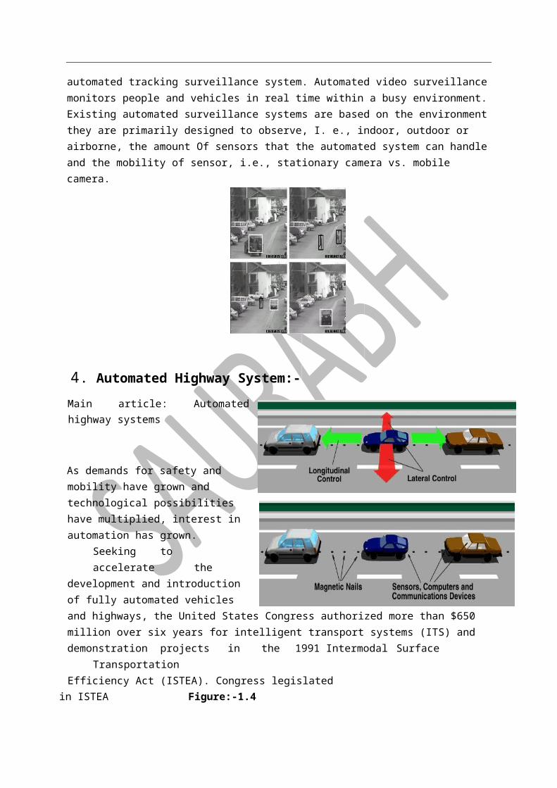
The Defense Advanced Research Projects Agency(DARPA) started the research and development of automated visual surveillance and monitoring (VSAM) program, between 1997 and 1999, and airborne video surveillance (AVS) programs, from 1998 to 2002. Currently, there is a major effort underway in the vision community to develop a fully automated tracking surveillance system. Automated video surveillance monitors people and vehicles in real time within a busy environment. Existing automated surveillance systems are based on the environment they are primarily designed to observe, I. e., indoor, outdoor or airborne, the amount Of sensors that the automated system can handle and the mobility of sensor, i.e., stationary camera vs. mobile camera.
4. Automated Highway System:-
Main article: Automated highway systems
As demands for safety and mobility have grown and technological possibilities have multiplied, interest in automation has grown. Seeking to
accelerate the development and introduction of fully automated vehicles and highways, the United States Congress authorized more than $650 million over six years for intelligent transport systems (ITS) and demonstration
projects in the 1991 Intermodal Surface Transportation Efficiency Act (ISTEA). Congress legislated
in ISTEA Figure:-1.4
that “the Secretary of Transportation shall develop an automated highway and vehicle prototype from which future fully automated intelligent vehicle-highway systems can be developed. Such development shall include research in human factors to ensure the success .
5 Automated Manufacturing:-
Main article: Numerical control
Automated manufacturing refers to the application of automation to produce things in the factory way. Most of the advantages of the automation Technology have its

influence in the manufacture. The main advantages of automated manufacturing higher consistency and quality, reduced lead times, Simplified production, reduced handling, improved work flow, and increased worker morale when a good implementation of the automation is made.
Figure:-1.5
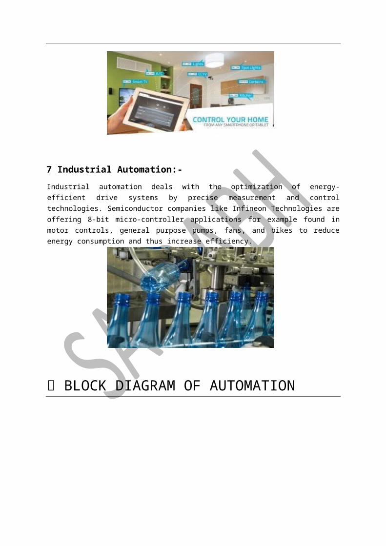
.6 Home Automation:-
Main article: Home automation
Home automation (also called domestics) designates An emerging practice of increased automation of household appliances and features in residential dwellings, particularly through electronic means that allow for things impracticable, overly expensive or Simply not possible in recent past decades.
Figure:- 1.6
7 Industrial Automation:-
Industrial automation deals with the optimization of energy-efficient drive systems by precise measurement and control technologies. Semiconductor companies like Infineon Technologies are offering 8-bit micro-controller applications for example found in motor controls, general purpose pumps, fans, and bikes to reduce energy consumption and thus increase efficiency.
BLOCK DIAGRAM OF AUTOMATION
GENERLY USED DEVICES
HARDWARE CONTROL
DEVICEFIELD
CONTROLHARDWARE
CONTROLSOFTWARE

PLC CNC PC BASED MICROPROCEESSOR ELECTRONIC LOGIC HARDWARE LOGIC MANUALY LOGIC
FIELD DEVICE
• SENSOR • PUMP
• MOTOR • VALVE etc.
SWITCH GEAR
RELAY SWITCHES
NO/NC SWITCH TOGGLE SWITCH
PROTOCOLS
PROTOCOLS –“GROUPS OF RULES AND INSTRUCTION IS CALLED PROTOCAL,ALSO EXCHANGE DATA IS CALLED PROTOCOLS.”
PROTOCOLS DEPEND ON-
SPEED LENGTH NODE CABLE NAME OF PROTOCOL-
RS232 RS485 ETHERNET
PROTOCOL &PARAMETER
S.N. PROTOCOL LENGTH SPEED NODE PLC 1. RS232 1.2M 19.2KBPS SINGLE ALLEN
BRADLY 2. RS485 1.2M 19.2KBPS SINGLE ALLEN
BRADLY 3 ETHERNET INFINITE 100MBPS INFINITE ALL 4. MPI 3.2M 100MBPS SINGLE SIEMENS 5. PROTIBUS INFINITE 100MBPS DOUBLE AB&SIMENS

CONTAIN OF CHAPTER
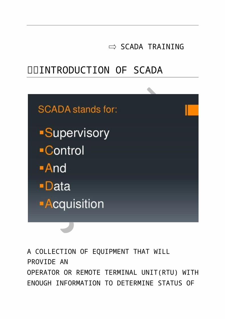
INTRODUCTION OF SCADA
HISTORY OF SCADA
OBJECTIVE OF SCADA
SCADA TRAINING INTRODUCTION OF SCADA

A COLLECTION OF EQUIPMENT THAT WILL PROVIDE AN OPERATOR OR REMOTE TERMINAL UNIT(RTU) WITH ENOUGH INFORMATION TO DETERMINE STATUS OF PERTICULAR PIECE OF EQUIPMENT AND ENTIRE SUBSTATION CAUSE ACTION TO MAKE PLACE REGARDING TO NEWORK BY COLLECTING INFORMATION FROM PLANT LIKE –VOLTAGE,CURRENT, FREQUENCY, POWER, CIRCUIT BREAKER STSTUS AND PERFORME ACTION.

HISTORY OF SCADA
OBJECTIVE OF SCADA

IMPORTANT POINTS
1.
PLC BRAND SOFTWARE ALLEN BRADLY R.S.VIEW(VS)
SIMENS WINE.(GERMAN)
WONDERWARE INTOUCH(KOREAN)
WONDERWARE SCADA INTERFACE WITH ALLEN BRADLY USING KYP SERVER
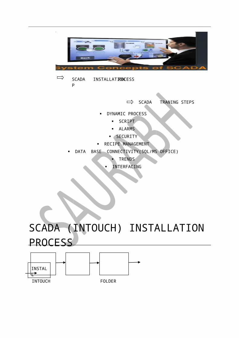
SCADA TRAINING
SCADA TRANING STEPS
DYNAMIC PROCESS SCRIPT ALARMS SECURITY
RECIPE MANAGEMENT DATA BASE CONNECTIVITY(SQL/MS OFFICE)
TRENDS
ROCESSSCADA INSTALLATION P
INTERFACING
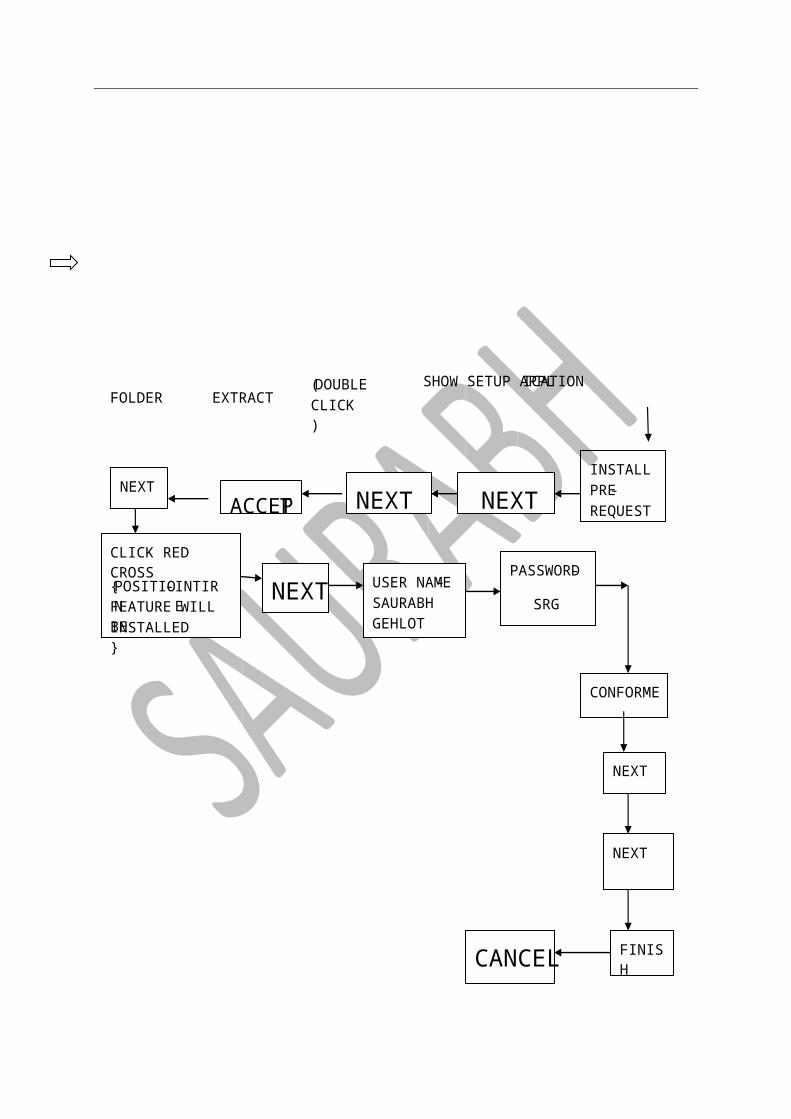
SCADA (INTOUCH) INSTALLATION PROCESS
INSTALL
INTOUCH FOLDER

CANCEL FINISH
NEXT
NEXT
CONFORME
SRG
-PASSWORD
GEHLOTSAURABH
-USER NAME NEXT INSTALLED}
FEATURE WILL BE INTIRE -POSITION{
CLICK RED CROSS
NEXTTACCEP
NEXT NEXT REQUEST
-PREINSTALL
CLICK)(DOUBLE
EXTRACT FOLDER
ICATION SHOW SETUP APPL

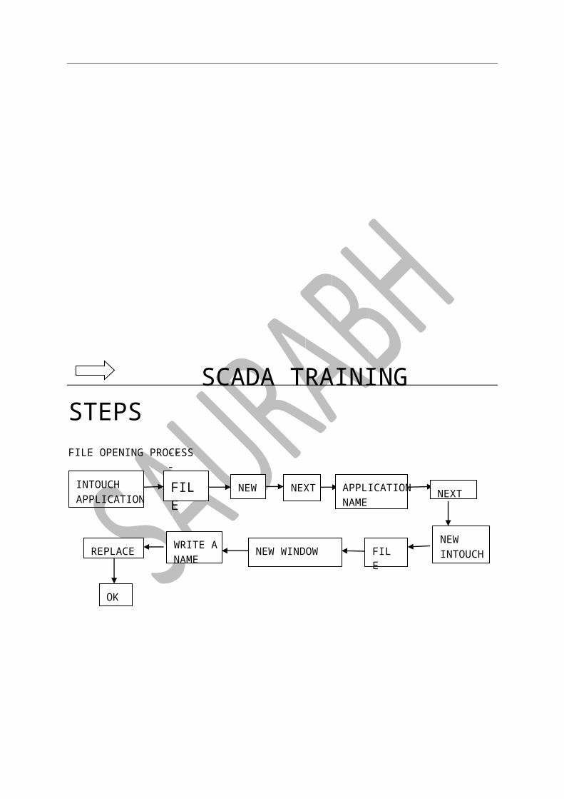
SCADA TRAINING STEPS
OK
REPLACE NAME
WRITE A NEW WINDOW FILE INTOUCH
NEW
NEXT NAME
APPLICATION NEXT NEW FILE APPLICATION
INTOUCH
---FILE OPENING PROCESS
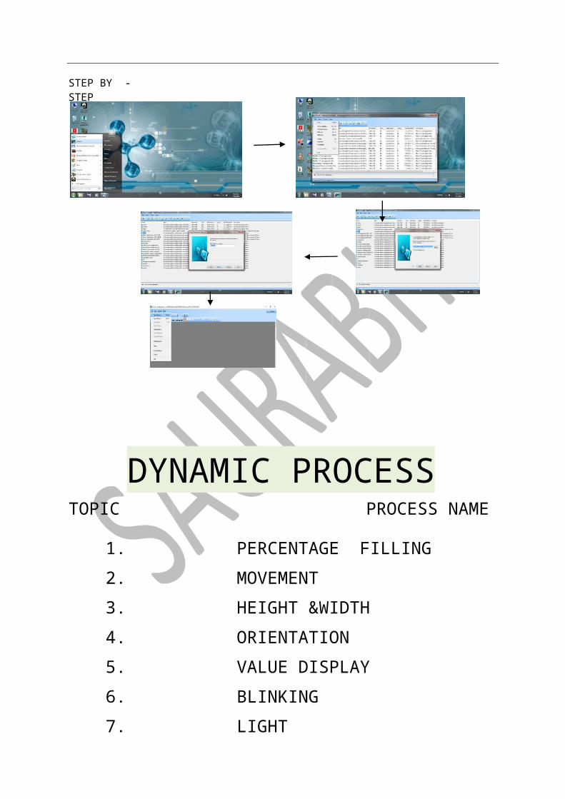
DYNAMIC PROCESS TOPIC PROCESS NAME
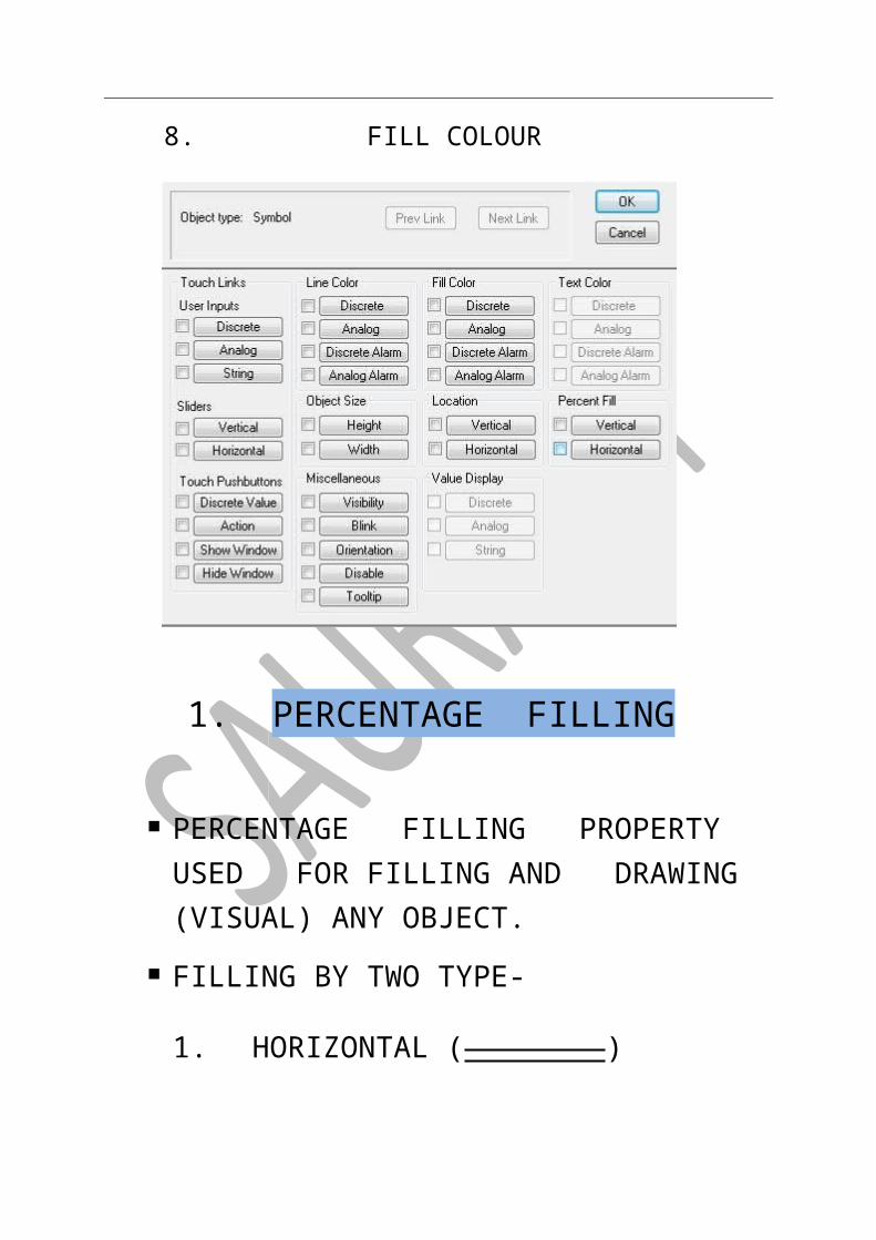
1. PERCENTAGE FILLING 2. MOVEMENT 3. HEIGHT &WIDTH 4. ORIENTATION 5. VALUE DISPLAY 6. BLINKING 7. LIGHT 8. FILL COLOUR
-STEP BY STEP
1. PERCENTAGE FILLING
PERCENTAGE FILLING PROPERTY USED FOR FILLING AND DRAWING (VISUAL) ANY OBJECT.
FILLING BY TWO TYPE- 1. HORIZONTAL ( ) 2. VERTICAL( ) NOTE- TAG NAME ARE MUST BE SAME OF OBJECT & SLIDER
SLIDER-
TASK 1 - ONE TANK FILLING
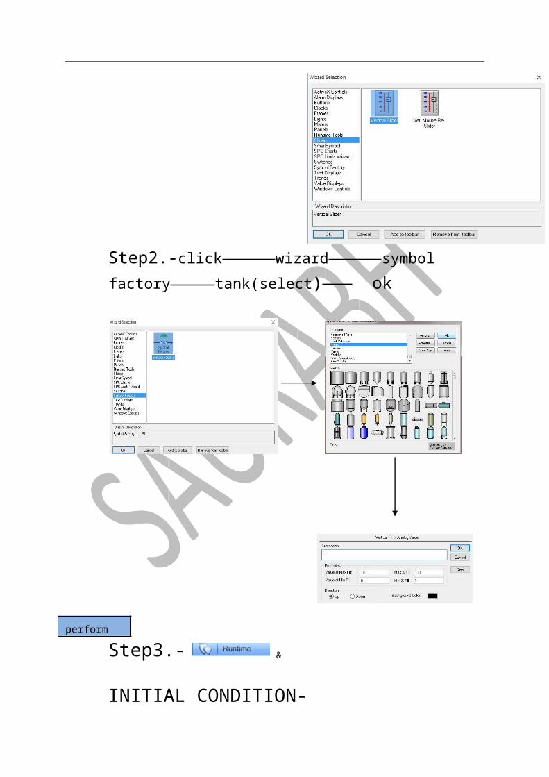
STEP1.- SELECT A SLIDER CLICK wizard( ) slider tag name(t)[memory real] save close
Step2.-click wizard symbol factory tank(select) ok
perform
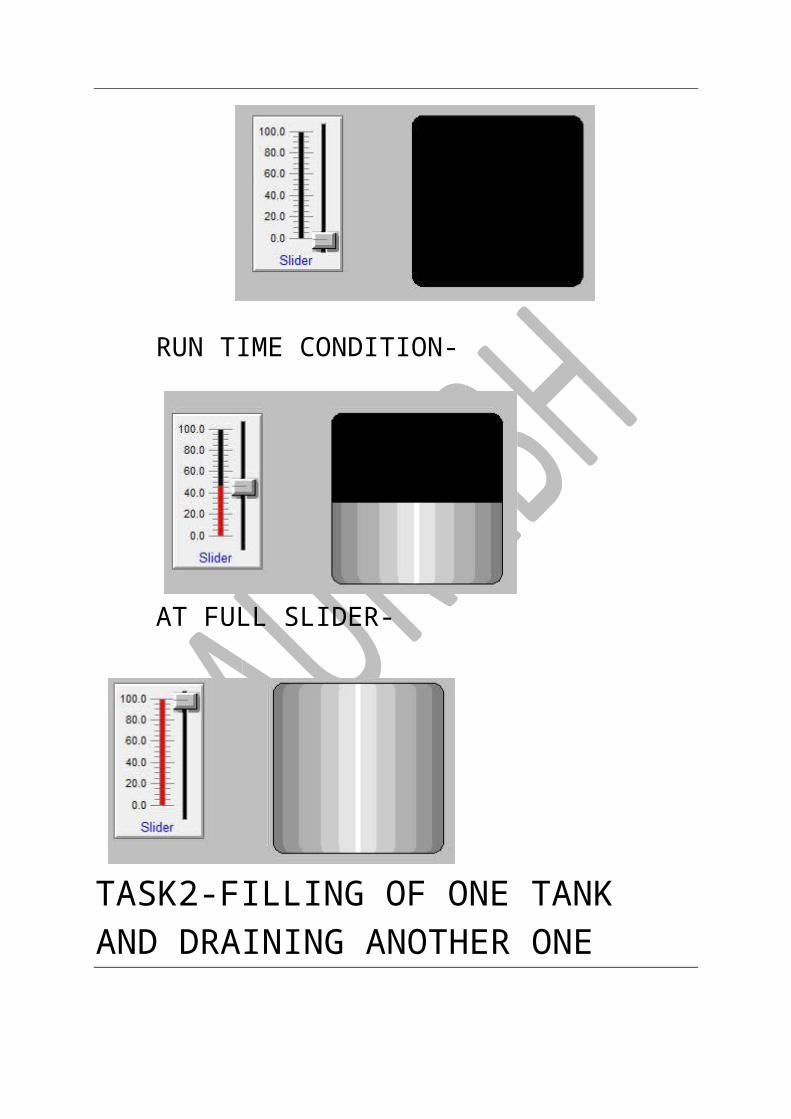
Step3.- & INITIAL CONDITION-
RUN TIME CONDITION-
AT FULL SLIDER-
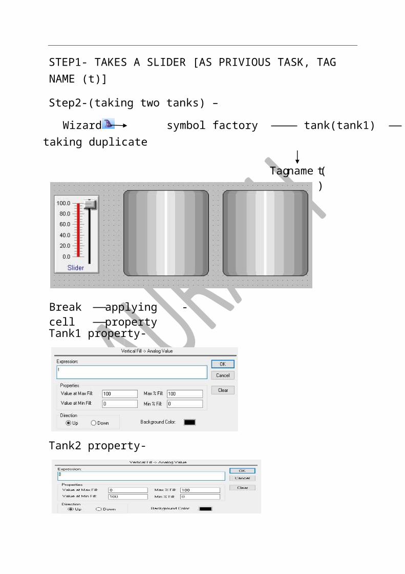
TASK2-FILLING OF ONE TANK AND DRAINING ANOTHER ONE
STEP1- TAKES A SLIDER [AS PRIVIOUS TASK, TAG NAME (t)]
Step2-(taking two tanks) –
Wizard symbol factory tank(tank1) taking duplicate

Tank1 property-
Tank2 property-
-applying property Break cell
t)name ( Tag
&
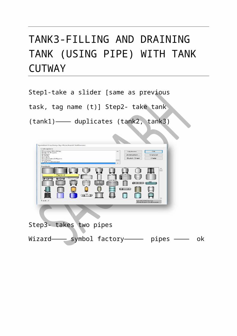
TANK3-FILLING AND DRAINING TANK (USING PIPE) WITH TANK CUTWAY
perform
& -Step3
Step1-take a slider [same as previous task, tag name (t)] Step2-
take tank (tank1) duplicates (tank2, tank3)
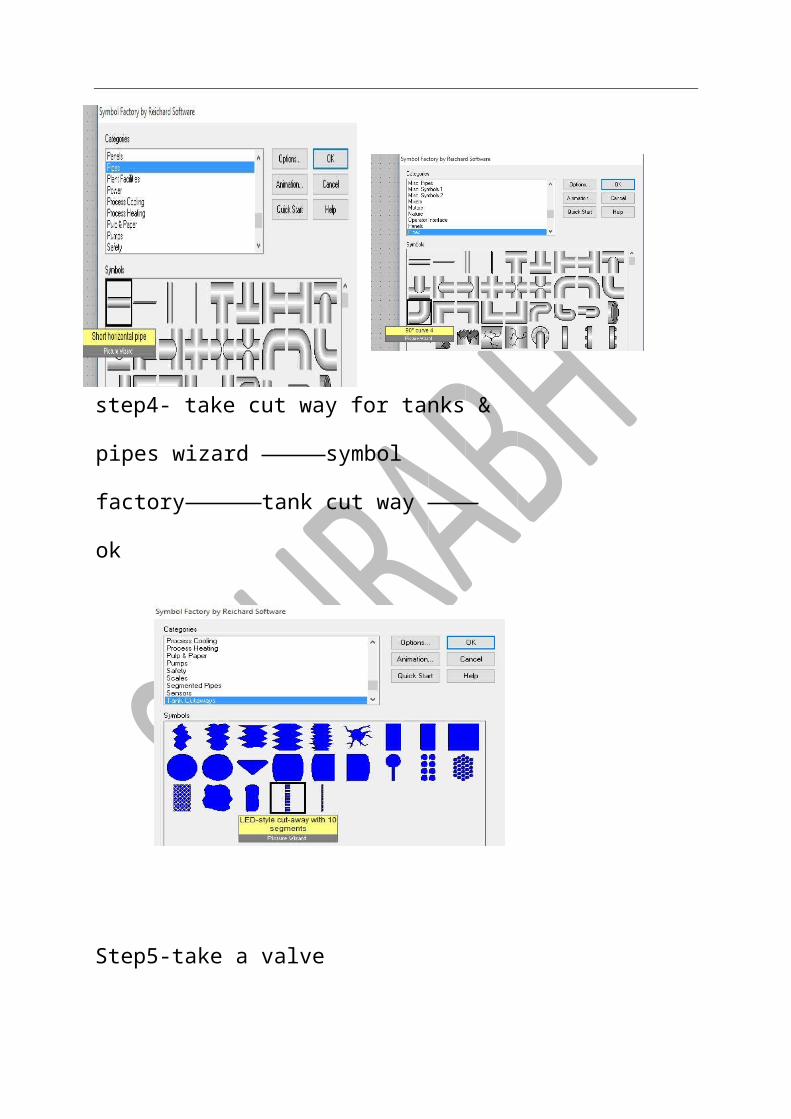
Step3- takes two pipes
Wizard symbol factory pipes ok
step4- take cut way for tanks & pipes wizard
symbol factory tank cut way ok
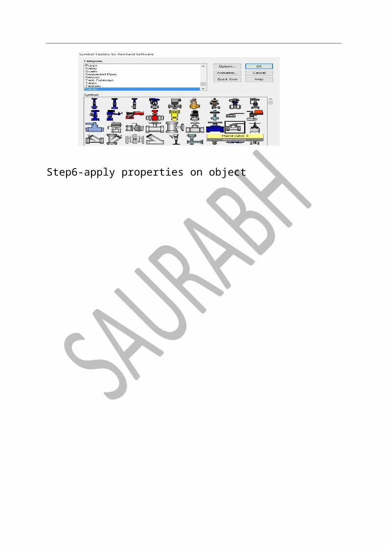
Step5-take a valve
Step6-apply properties on object

perform
Pipe cutway
Tank3 cut way
Tank1cutway
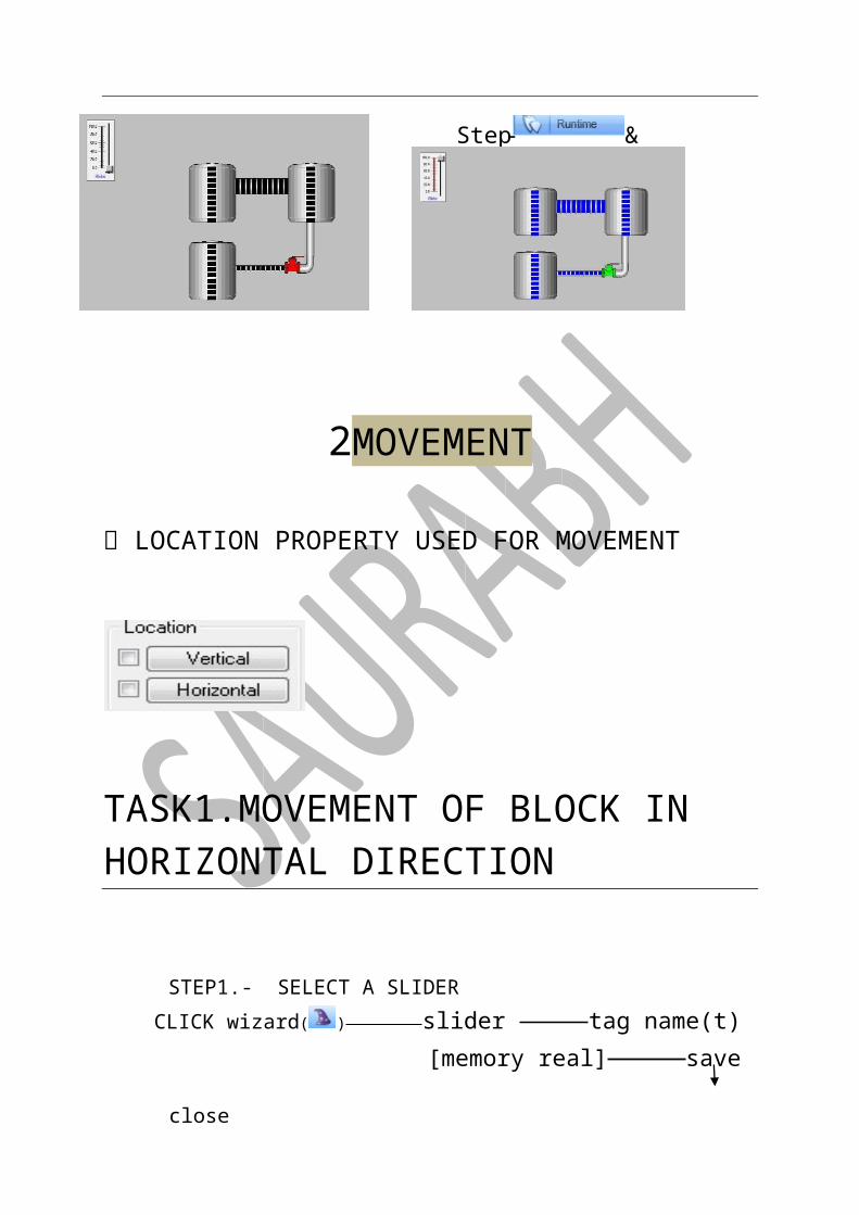
2MOVEMENT
LOCATION PROPERTY USED FOR MOVEMENT
TASK1.MOVEMENT OF BLOCK IN HORIZONTAL DIRECTION
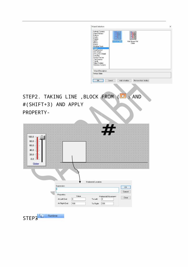
STEP1.- SELECT A SLIDER CLICK wizard( ) slider tag name(t)[memory real] save close
& -Step7
STEP2. TAKING LINE ,BLOCK FROM ( ) AND #(SHIFT+3) AND APPLY PROPERTY-
-STEP3
&
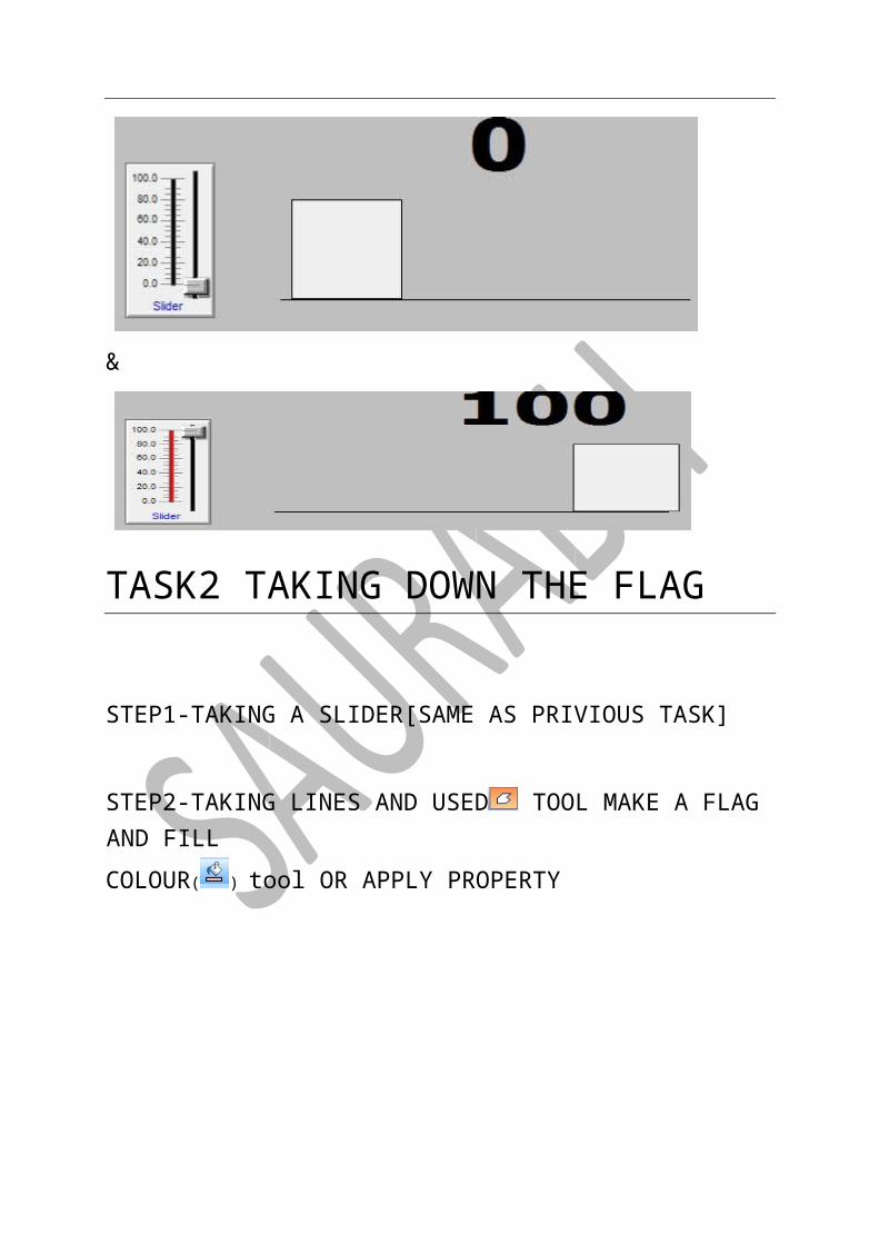
TASK2 TAKING DOWN THE FLAG
STEP1-TAKING A SLIDER[SAME AS PRIVIOUS TASK]
STEP2-TAKING LINES AND USED TOOL MAKE A FLAG AND FILL
COLOUR( ) tool OR APPLY PROPERTY

TASK3.MOVING BOX HORIZONTAL & VERTICAL
STEP1.TAKE A SLIDER[SAME AS PRIVIOUS TASK]
STEP2-TAKING LINE AND BOX BY AND TAKING #[MEMORY REAL]
AND APPLY PROPERTY (HORIZONTAL &VERTICAL)
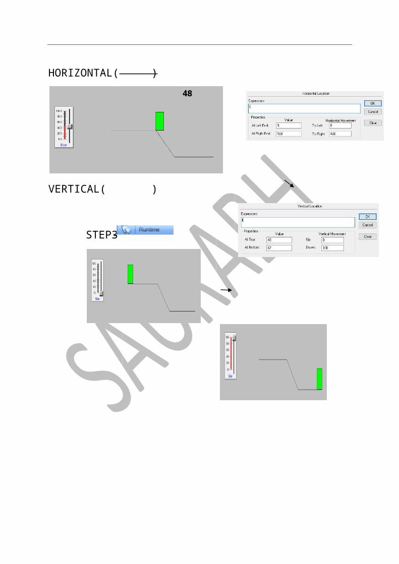
HORIZONTAL( )
VERTICAL( )
-STEP3
-STEP3
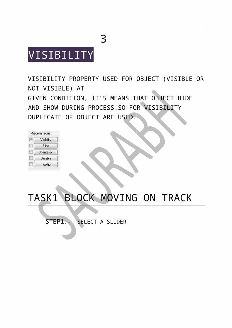
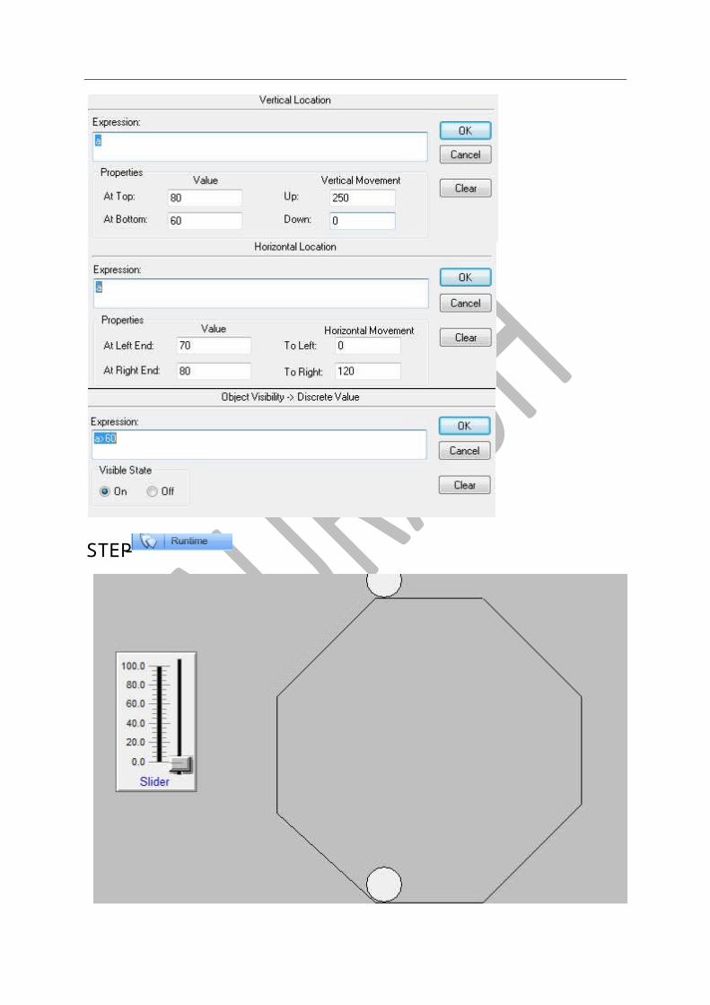
3 VISIBILITY
VISIBILITY PROPERTY USED FOR OBJECT (VISIBLE OR NOT VISIBLE) AT GIVEN CONDITION, IT’S MEANS THAT OBJECT HIDE AND SHOW DURING PROCESS.SO FOR VISIBILITY DUPLICATE OF OBJECT ARE USED.
TASK1 BLOCK MOVING ON TRACK
STEP1.- SELECT A SLIDER
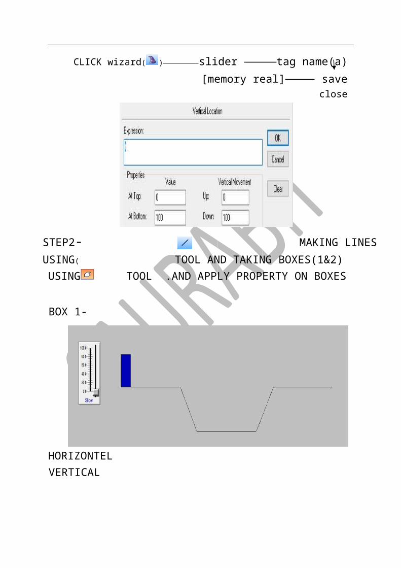
CLICK wizard( ) slider tag name(a)[memory real] save close
STEP2-MAKING LINES USING( TOOL AND TAKING BOXES(1&2)
USING TOOL .AND APPLY PROPERTY ON BOXES
BOX 1-
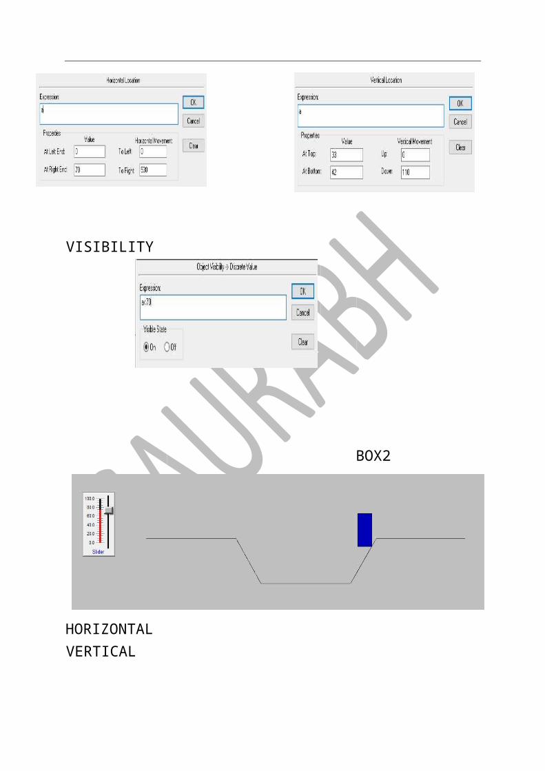
HORIZONTEL VERTICAL
VISIBILITY
BOX2

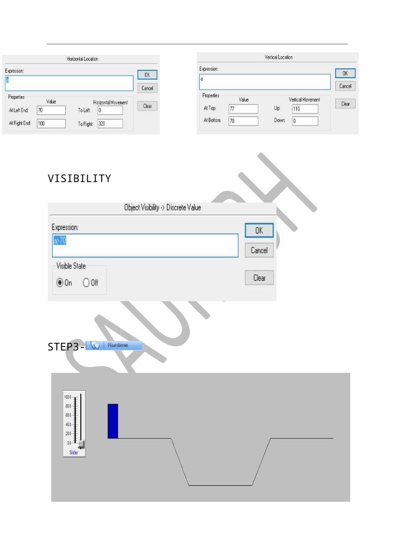
HORIZONTAL VERTICAL
VISIBILITY
STEP3-
&
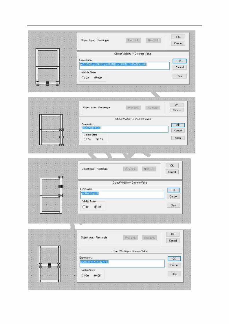
TASK2 SEVEN SEGMENT USING SLIDER STEP1- TAKE A SLIDER[SAME AS PERIVIOUS TASK,TAG NAME(P)]
STEP2-MAKING SQAURE, ARRANGE IN 8 FORM FOR SEVEN SEGMENT DISPLAY AND APPLY PROPERTY
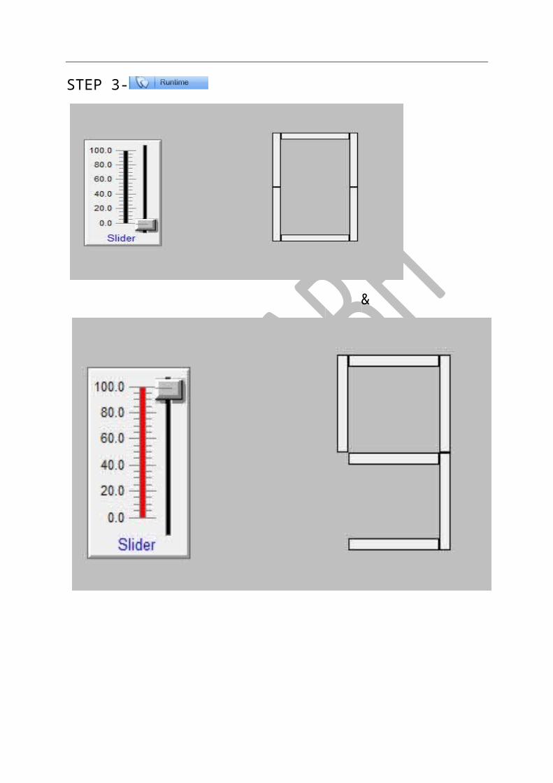
STEP 3-
&
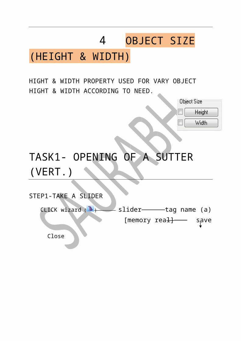
4 OBJECT SIZE (HEIGHT & WIDTH)
HIGHT & WIDTH PROPERTY USED FOR VARY OBJECT HIGHT & WIDTH ACCORDING TO NEED.
TASK1- OPENING OF A SUTTER (VERT.)
STEP1-TAKE A SLIDER
CLICK wizard ( ) slider tag name (a)[memory real] save Close
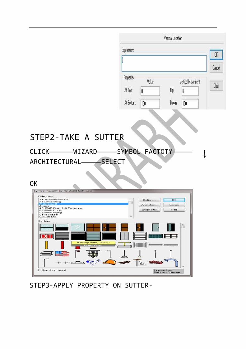
STEP2-TAKE A SUTTER CLICK WIZARD SYMBOL FACTOTY ARCHITECTURAL SELECT
OK

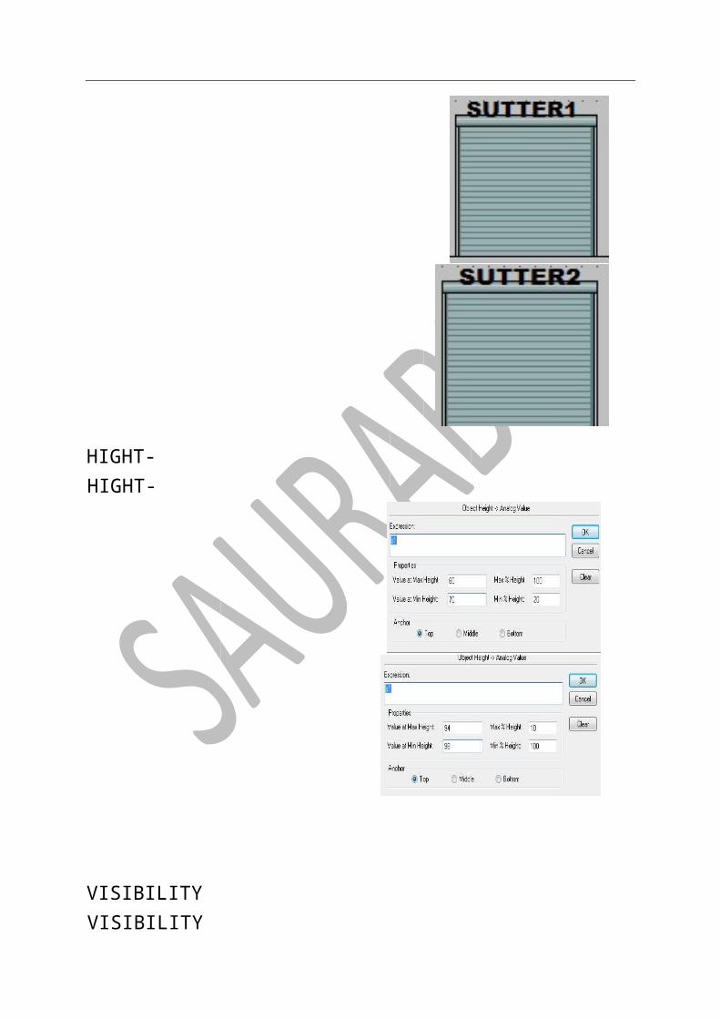
STEP3-APPLY PROPERTY ON SUTTER-
TASK2 CAR PARKING IN GARGE STEP1 SAME AS PRIVIOUS TASK[TAG NAME (S1),MEMORY REAL]
STEP2 TAKING A SUTTER [SAME AS PRIVIOUS ] AND
STEP4

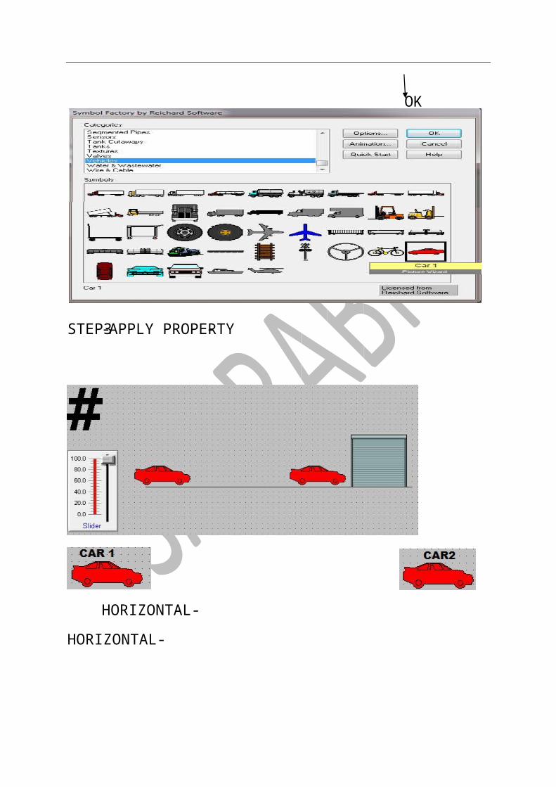
TAKING A CAR-
CLICK-WIZARD SYMBOLE FACTORY VEHICLES SELECT VEHICLE
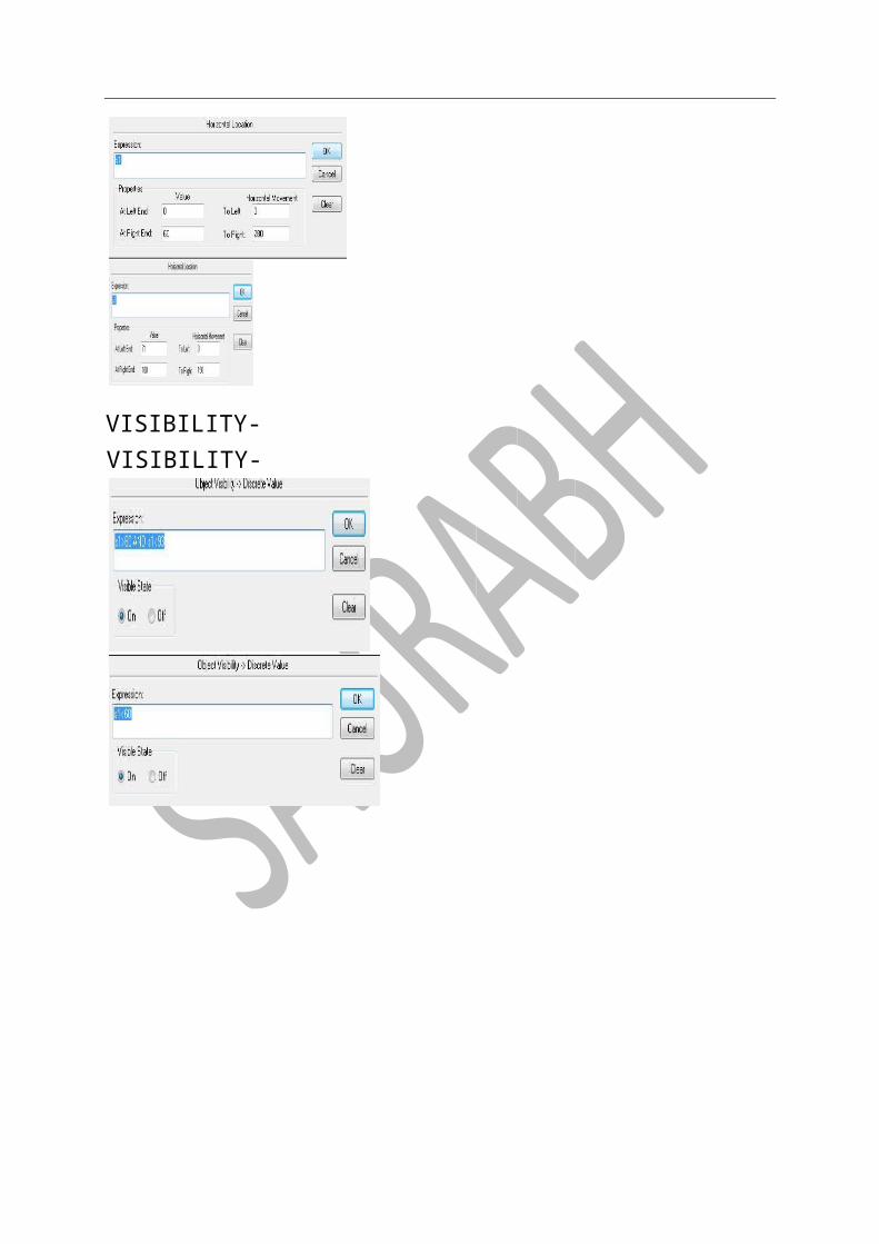
HORIZONTAL- HORIZONTAL-
-APPLY PROPERTY -STEP3
OK
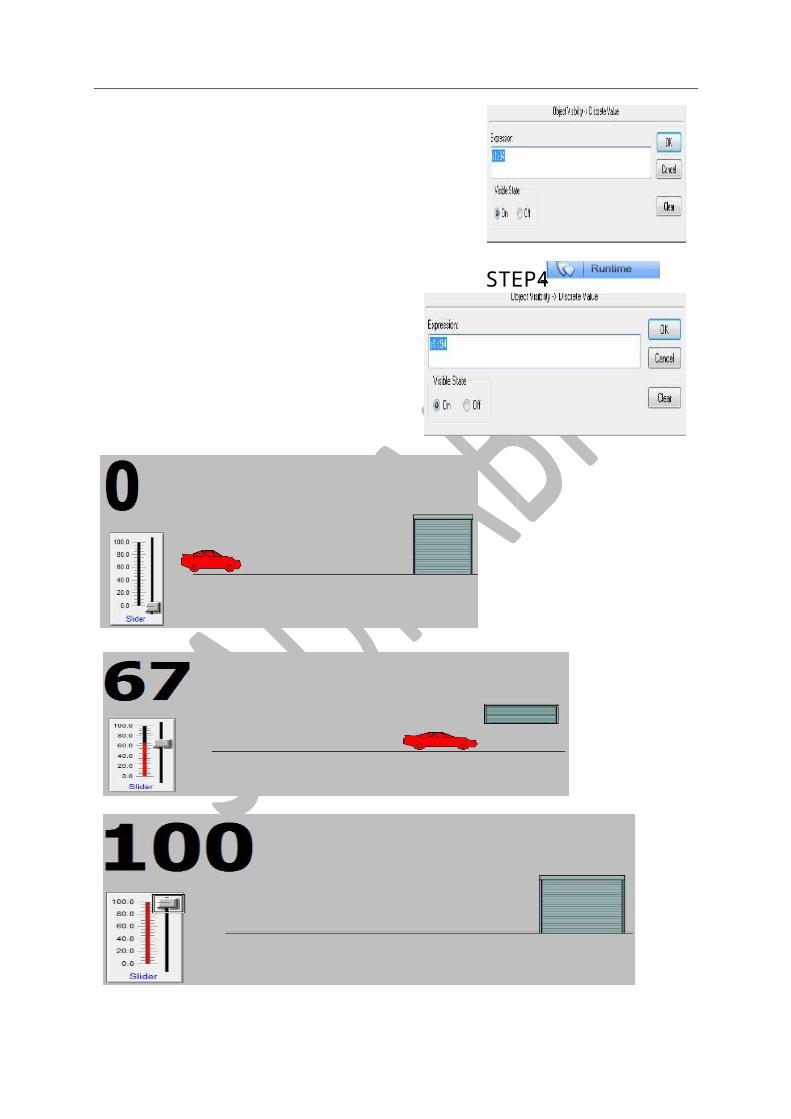
VISIBILITY- VISIBILITY-
HIGHT- HIGHT-
VISIBILITY VISIBILITY
TASK3 MOVING BALL USING HOOK
DRAWING PART-
STEP1-TAKE A SLIDER [SAME AS PREVIOUS STEP,TAG NAME(MP)]
-STEP4
STEP2- TAKE A BOX HOOK
WIZARD SYMBOLE FACTOTY INTOUCH OBJECTS BOX HOOK
TAKE A BALL-
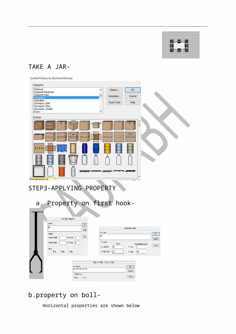
TAKE A JAR-
STEP3-APPLYING PROPERTY
a. Property on first hook-
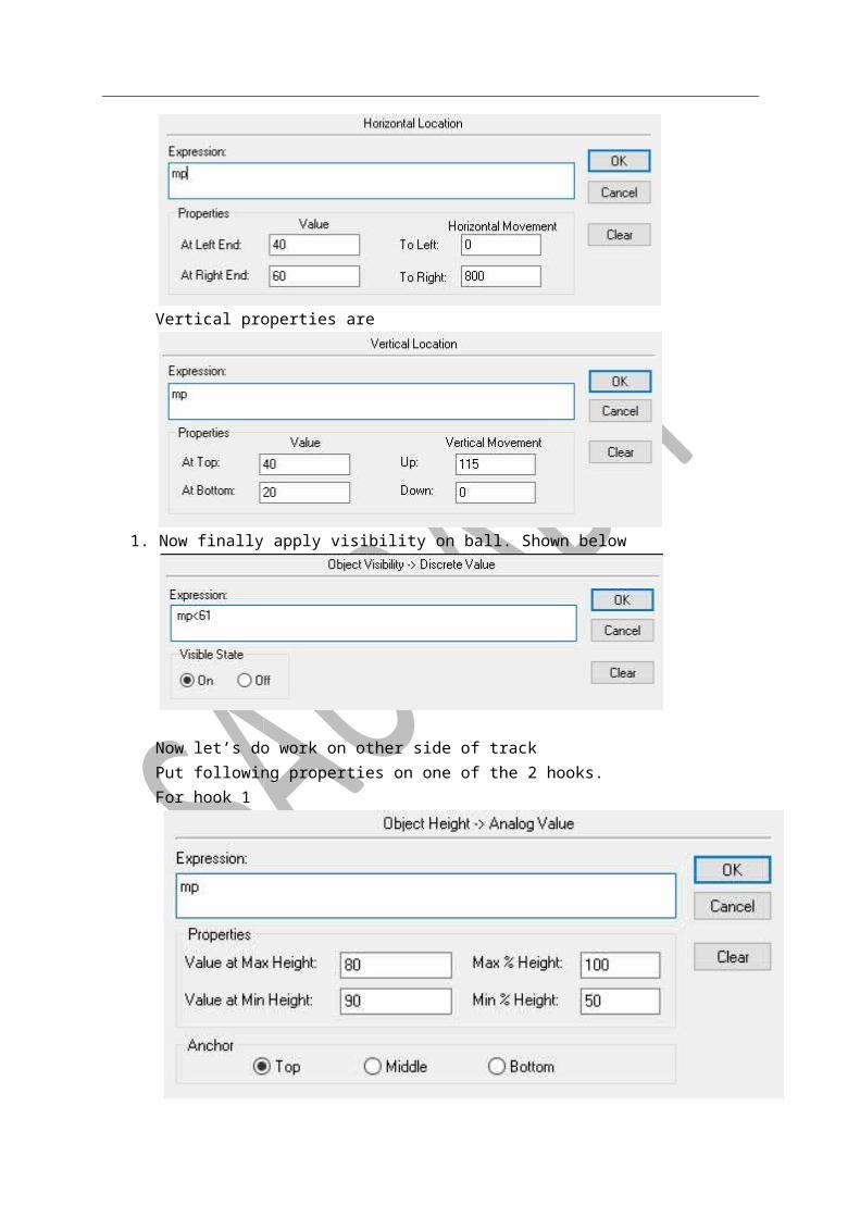
b.property on boll- Horizontal properties are shown below

Vertical properties are
1. Now finally apply visibility on ball. Shown below
Now let’s do work on other side of track Put following properties on one of the 2 hooks. For hook 1
For hook2
On ball-
Step-
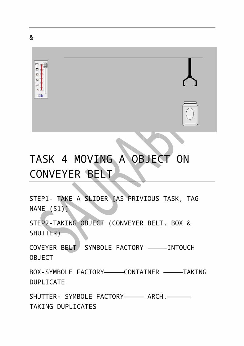
&
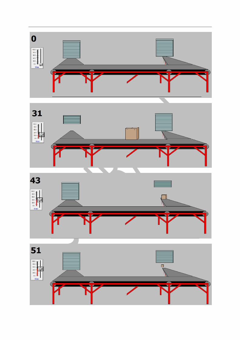
TASK 4 MOVING A OBJECT ON CONVEYER BELT
STEP1- TAKE A SLIDER [AS PRIVIOUS TASK, TAG NAME (S1)]
STEP2-TAKING OBJECT (CONVEYER BELT, BOX & SHUTTER)
COVEYER BELT- SYMBOLE FACTORY INTOUCH OBJECT
BOX-SYMBOLE FACTORY CONTAINER TAKING DUPLICATE
SHUTTER- SYMBOLE FACTORY ARCH. TAKING DUPLICATES
STEP3- DRAW AS SHOWN-[2 SHUTTER GROP OVERLAPE]
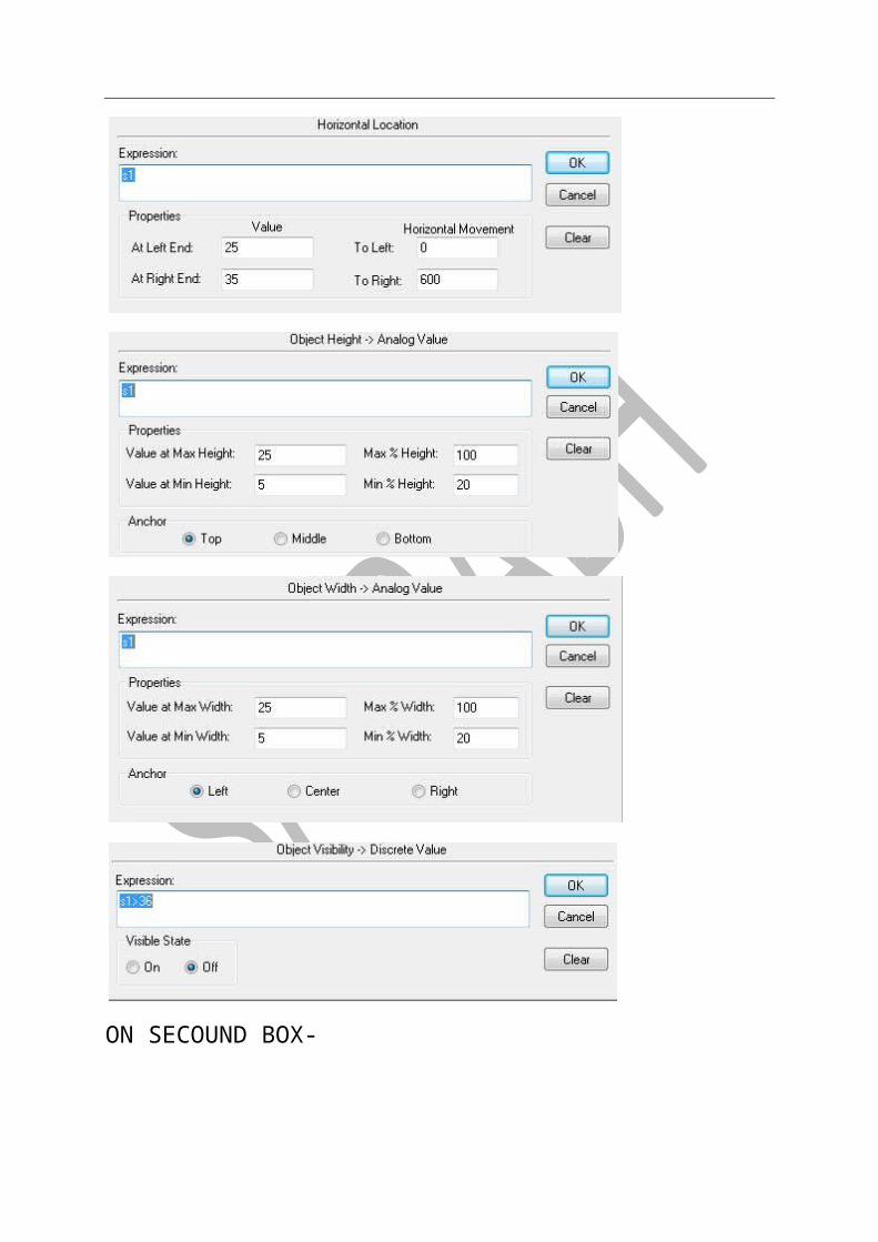
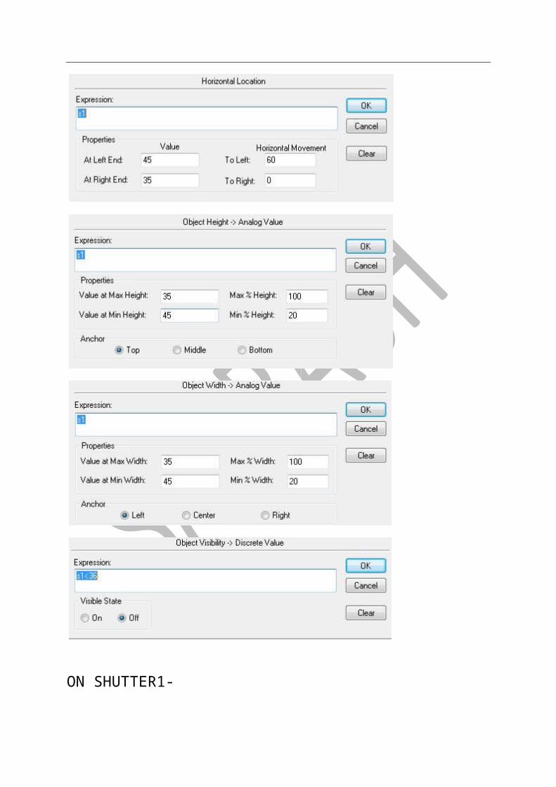
STEP4-APPLY PROPERTY-
ON FIRST BOX-
ON SECOUND BOX-

ON SHUTTER1-
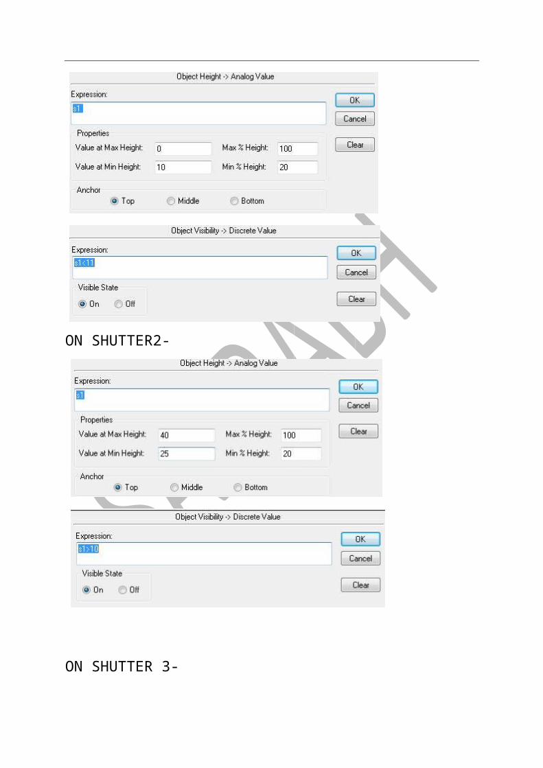
ON SHUTTER2-
ON SHUTTER 3-
ON SHUTTER4-
-STEP5


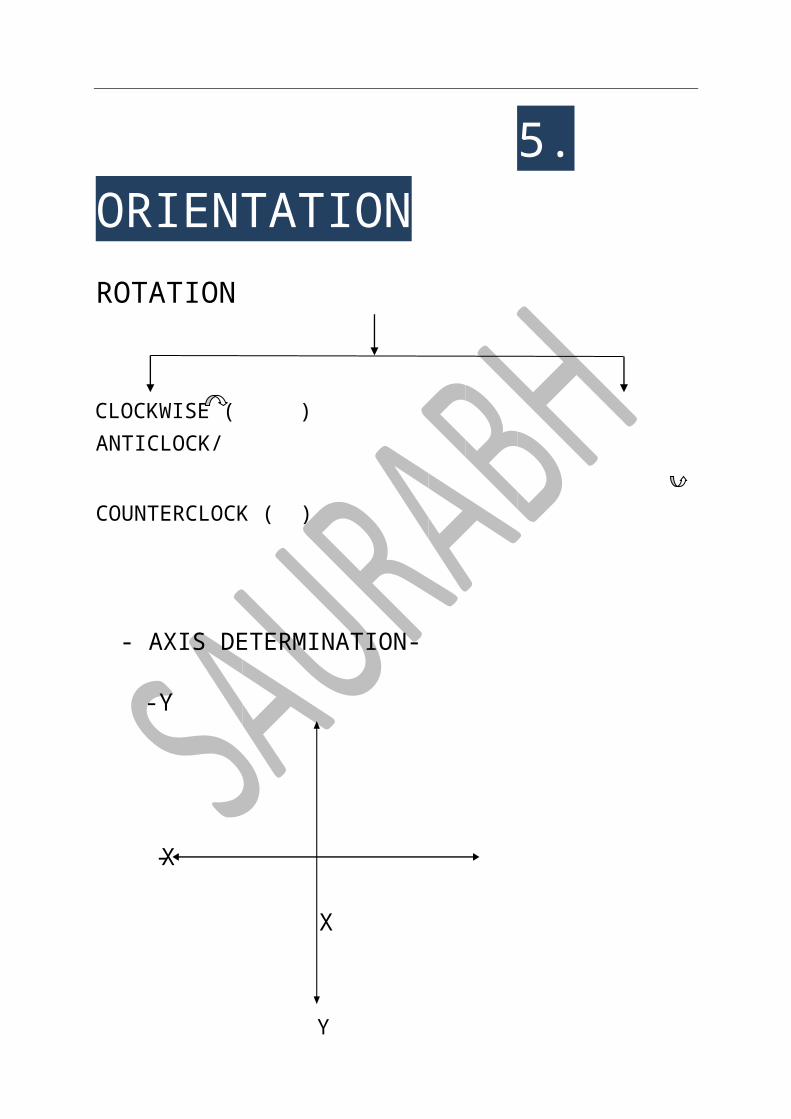
5. ORIENTATION ROTATION
CLOCKWISE ( ) ANTICLOCK/
COUNTERCLOCK ( )
- AXIS DETERMINATION- -Y
Y
X X-
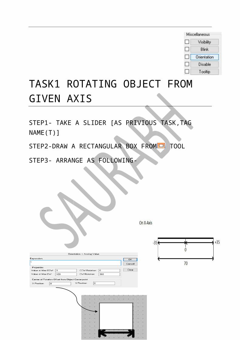
TASK1 ROTATING OBJECT FROM GIVEN AXIS
STEP1- TAKE A SLIDER [AS PRIVIOUS TASK,TAG NAME(T)]
STEP2-DRAW A RECTANGULAR BOX FROM TOOL
STEP3- ARRANGE AS FOLLOWING-

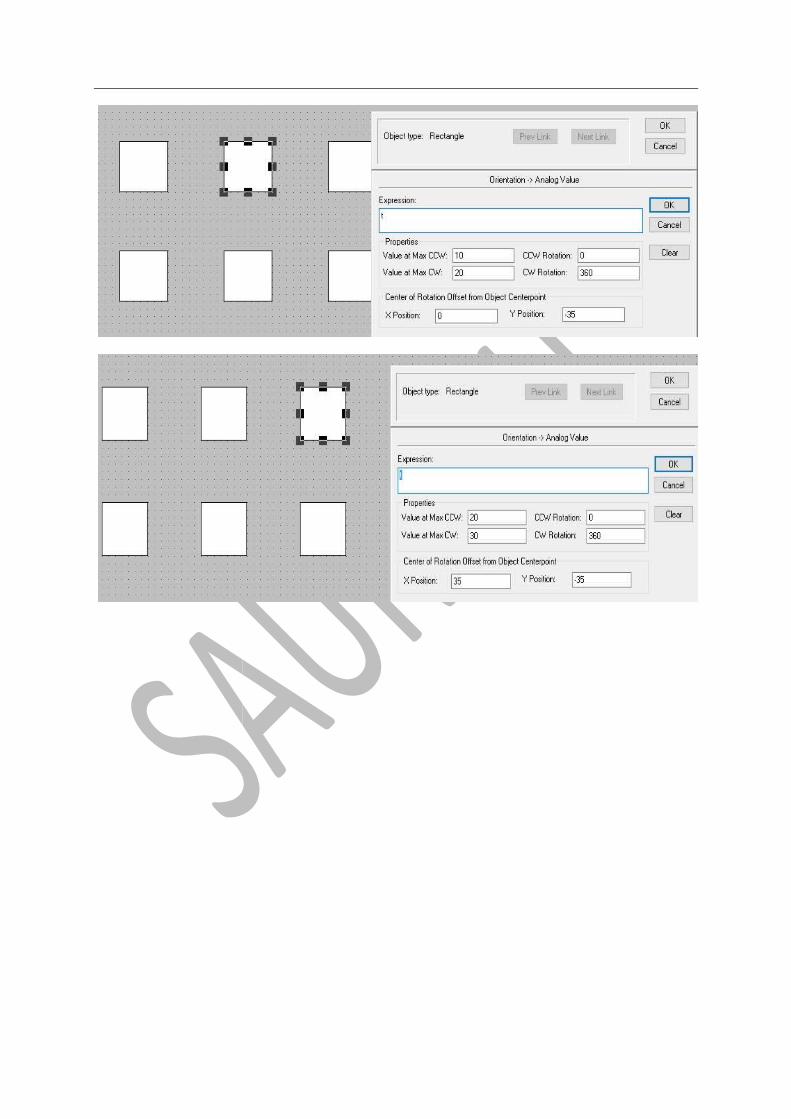
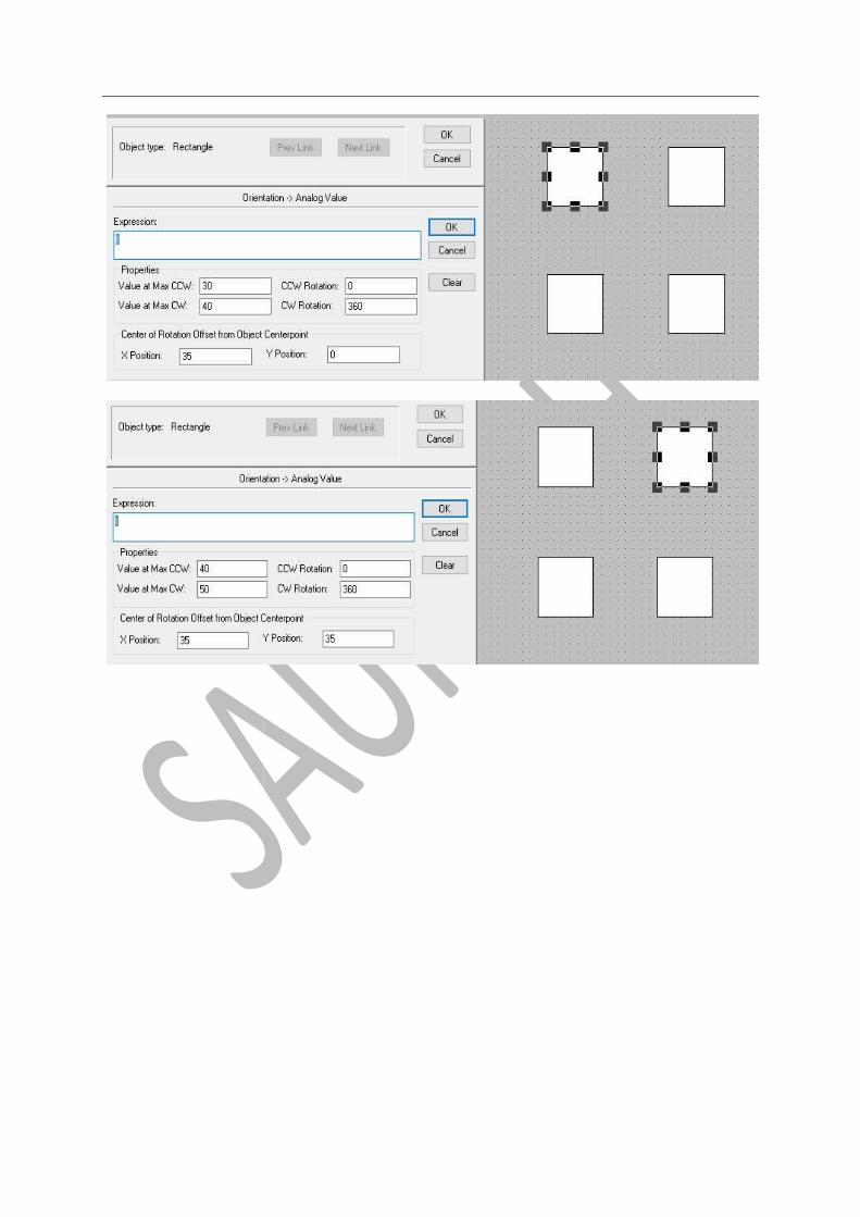
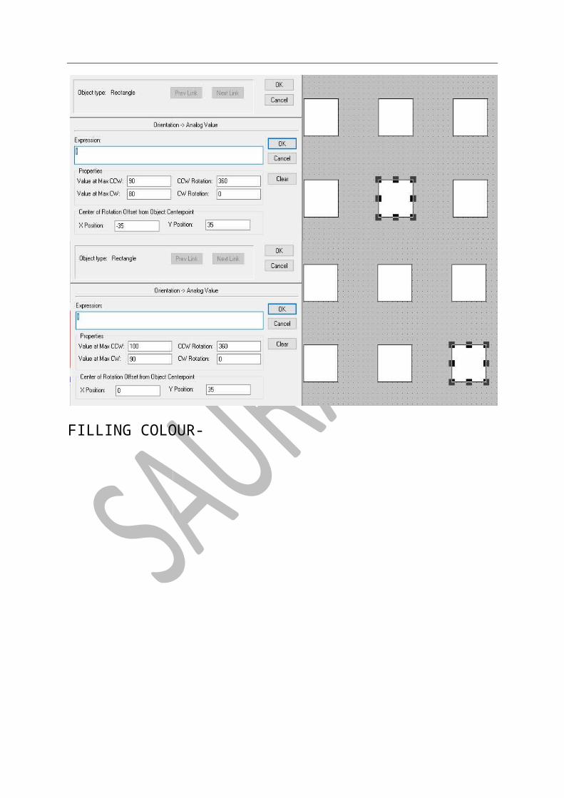
MEASURE OF BOX & APPLY PROPERTY -
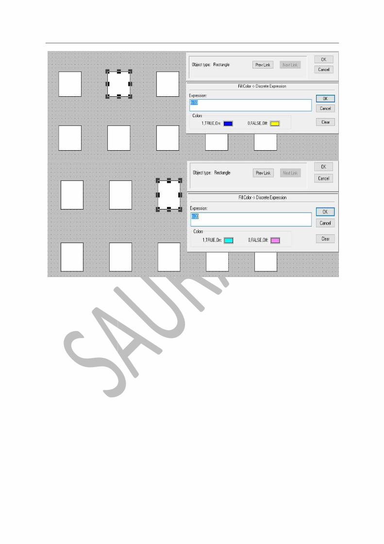
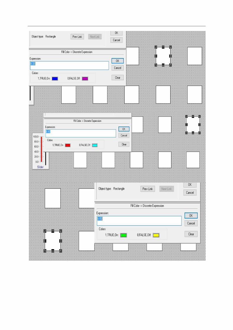
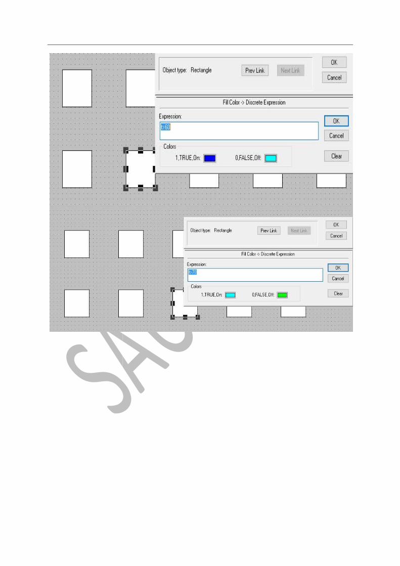
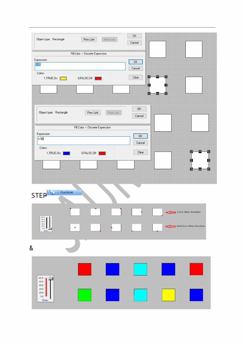
Task 2: Rotating 10 objects one by one at given points (with also change in color)
STEP1-TAKING A SLIDER [SAME AS PRIVIOUS TASK]
STEP2 –DRAW 10 OBJECT (SIMILAR SIZE) BY TOOL, FILL COLOUR AND ARRANGE IN FOLLOWING MANNER-
-STEP4
STEP3-APPLY PROPERTY-

FILLING COLOUR-

&
-STEP

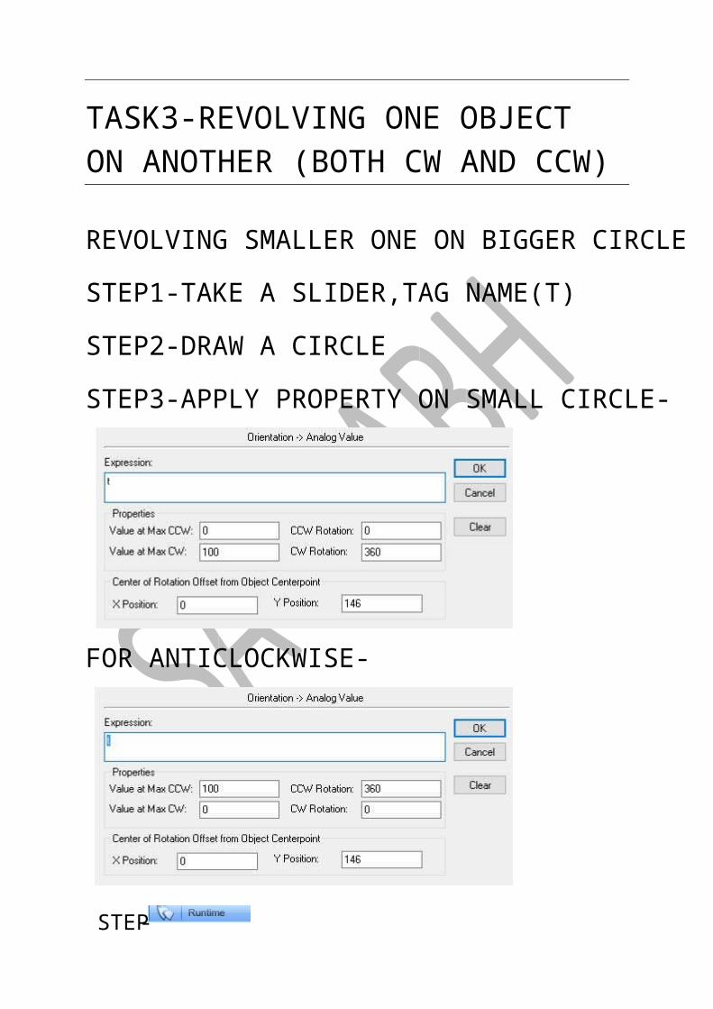
TASK3-REVOLVING ONE OBJECT ON ANOTHER (BOTH CW AND CCW)
REVOLVING SMALLER ONE ON BIGGER CIRCLE
STEP1-TAKE A SLIDER,TAG NAME(T)
STEP2-DRAW A CIRCLE
STEP3-APPLY PROPERTY ON SMALL CIRCLE-
FOR ANTICLOCKWISE-
-STEP
&
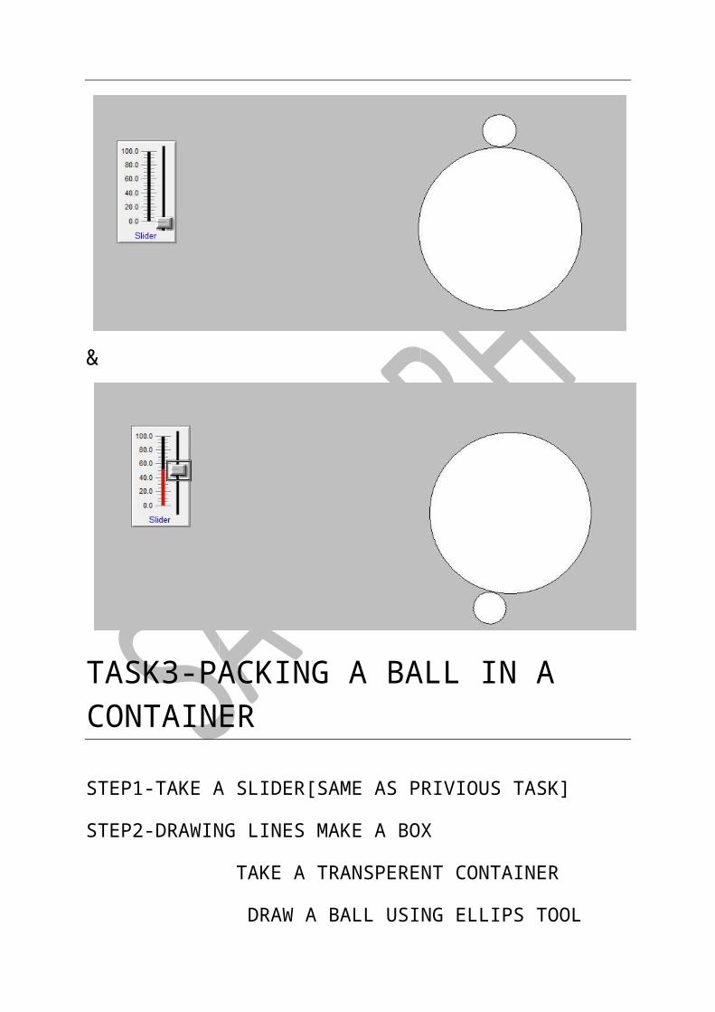
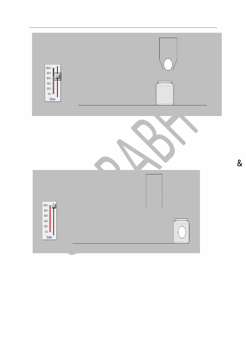
TASK3-PACKING A BALL IN A CONTAINER
STEP1-TAKE A SLIDER[SAME AS PRIVIOUS TASK]
STEP2-DRAWING LINES MAKE A BOX
TAKE A TRANSPERENT CONTAINER
DRAW A BALL USING ELLIPS TOOL
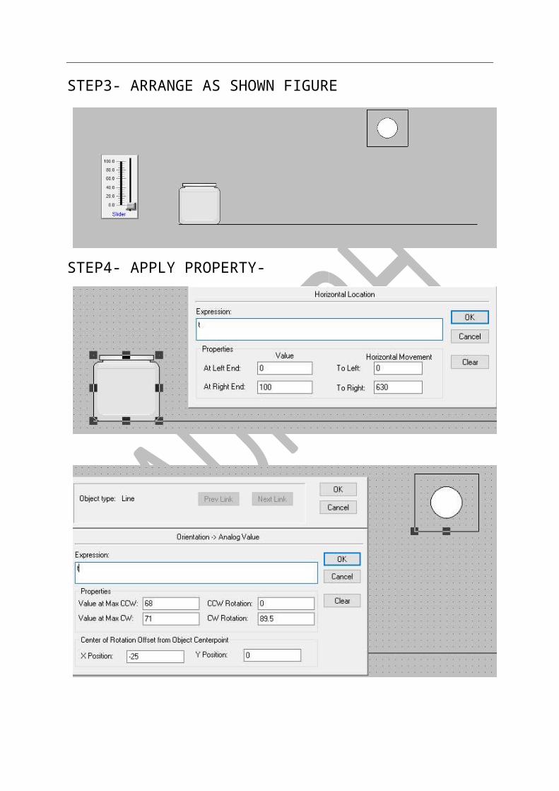
STEP3- ARRANGE AS SHOWN FIGURE
STEP4- APPLY PROPERTY-

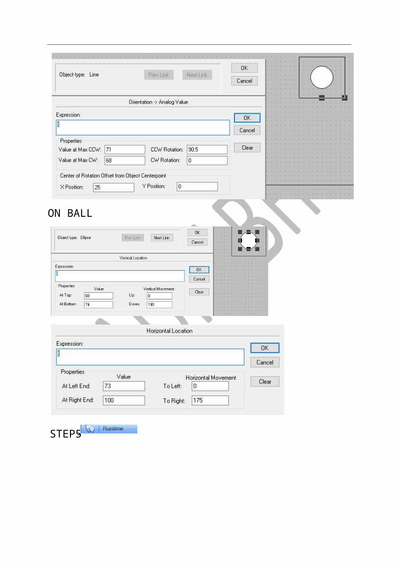
ON BALL
-STEP5
&
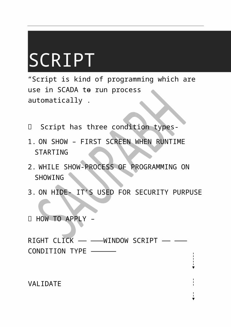
SCRIPT “Script is kind of programming which are use in SCADA to run process automatically”.
Script has three condition types-
1. ON SHOW – FIRST SCREEN WHEN RUNTIME STARTING
2. WHILE SHOW-PROCESS OF PROGRAMMING ON SHOWING
3. ON HIDE- IT’S USED FOR SECURITY PURPUSE
HOW TO APPLY –
RIGHT CLICK WINDOW SCRIPT CONDITION TYPE
VALIDATE
OK
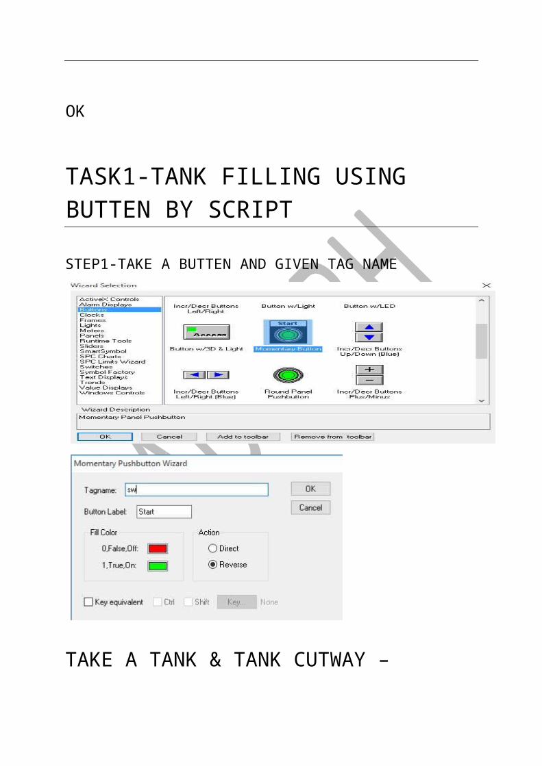
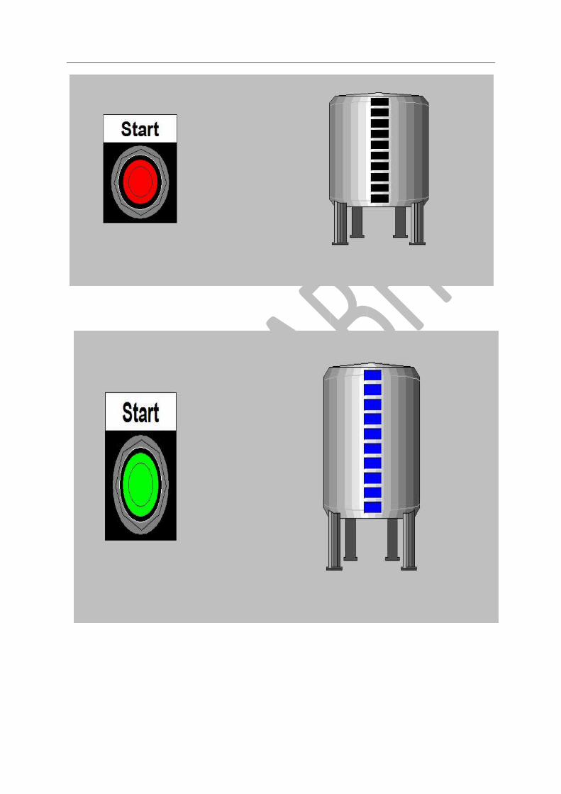
TASK1-TANK FILLING USING BUTTEN BY SCRIPT
STEP1-TAKE A BUTTEN AND GIVEN TAG NAME
TAKE A TANK & TANK CUTWAY –
SCRIPT WRITING-
3-STEP
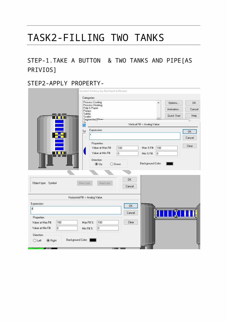
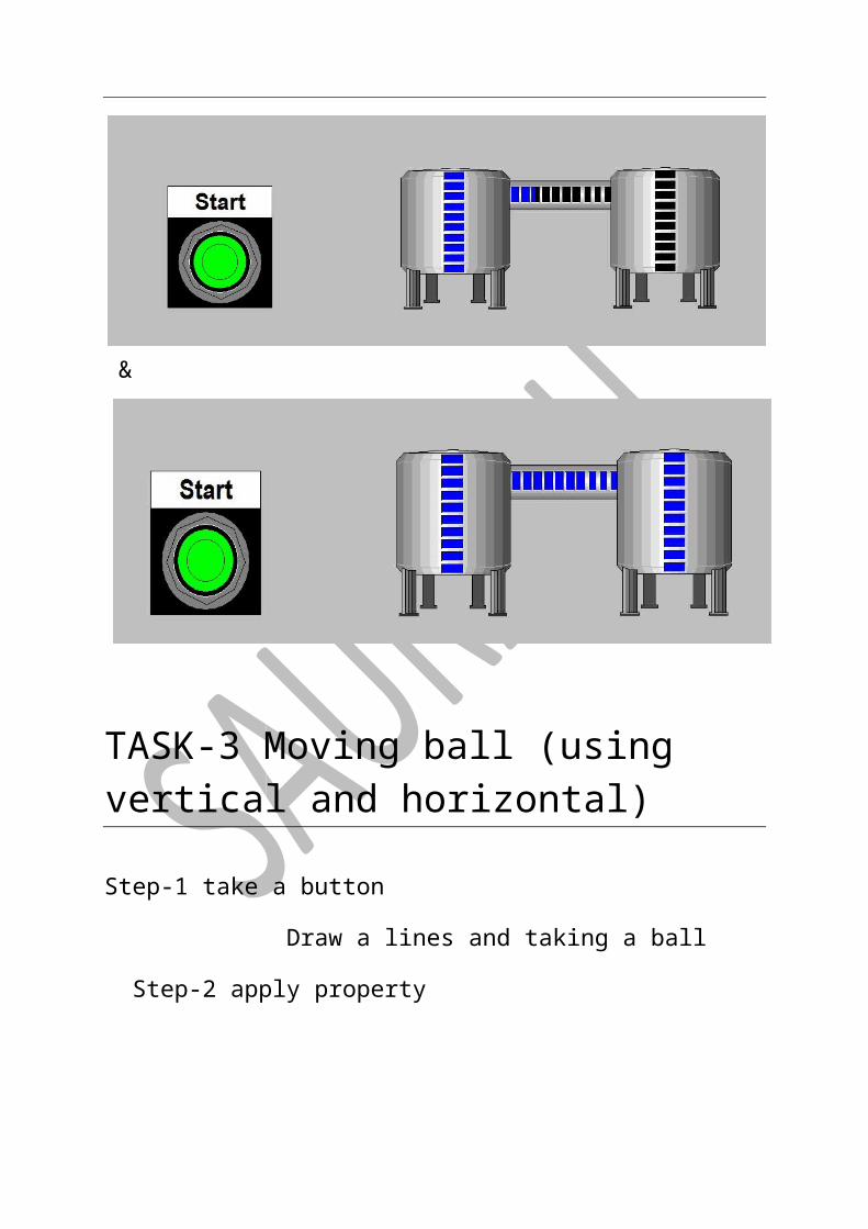
TASK2-FILLING TWO TANKS
STEP-1.TAKE A BUTTON & TWO TANKS AND PIPE[AS PRIVIOS]
STEP2-APPLY PROPERTY-
STEP3-SCRIPT
&
4-STEP
TASK-3 Moving ball (using vertical and horizontal)
Step-1 take a button
Draw a lines and taking a ball
Step-2 apply property
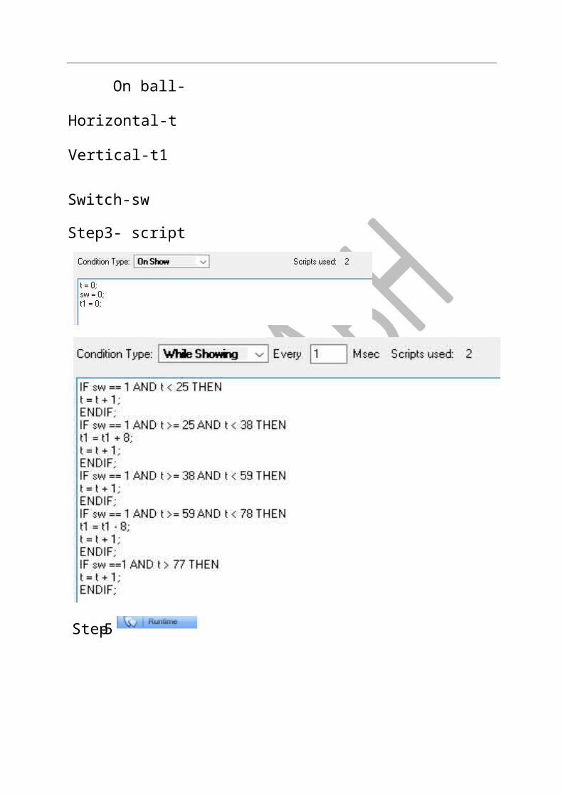
On ball-
Horizontal-t Vertical-t1
Switch-sw
Step3- script
5-Step
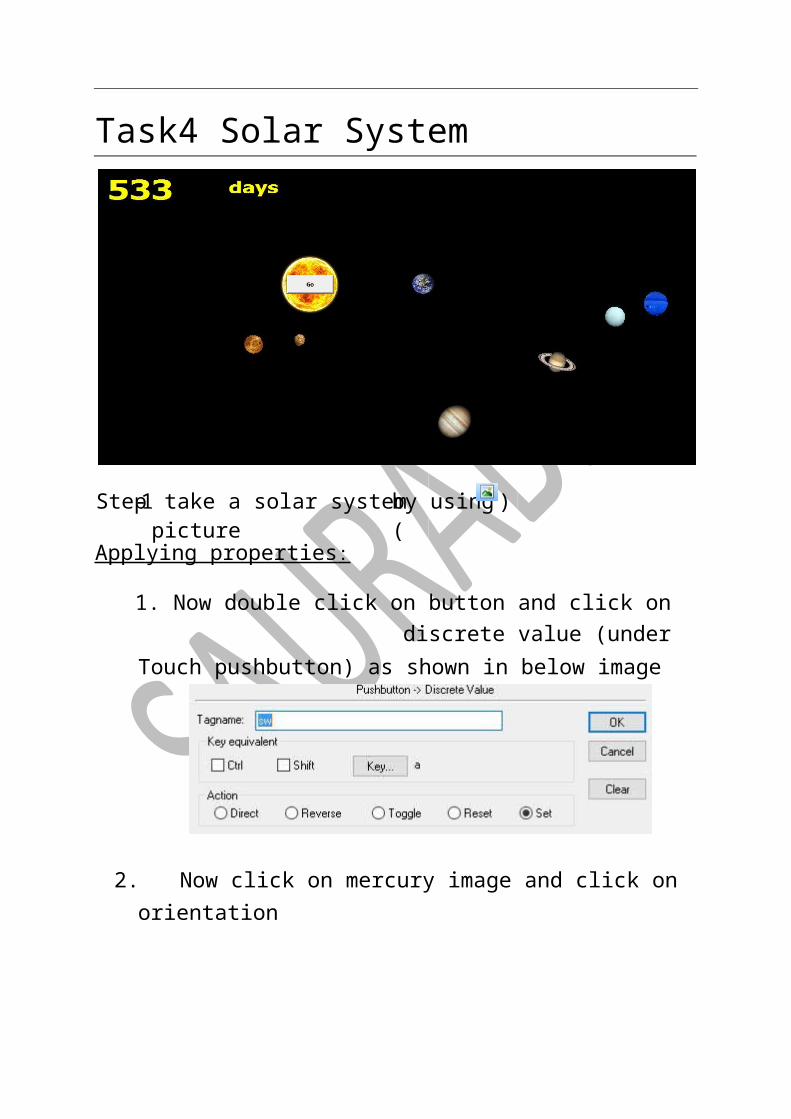
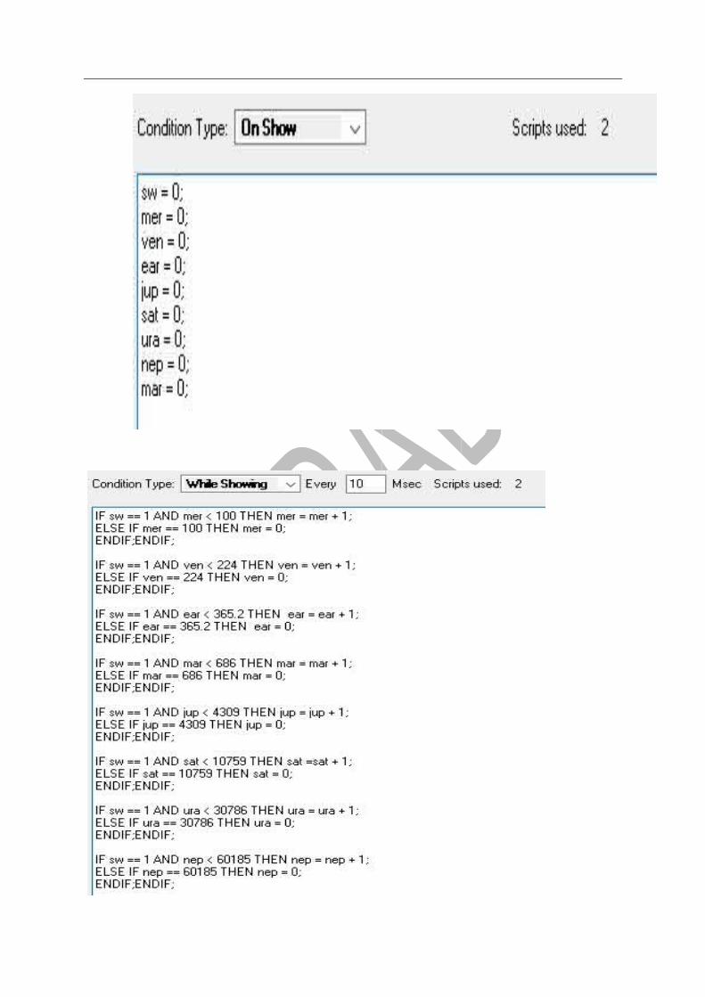
Task4 Solar System
Applying properties :
1. Now double click on button and click on discrete value (under Touch pushbutton) as shown in below image
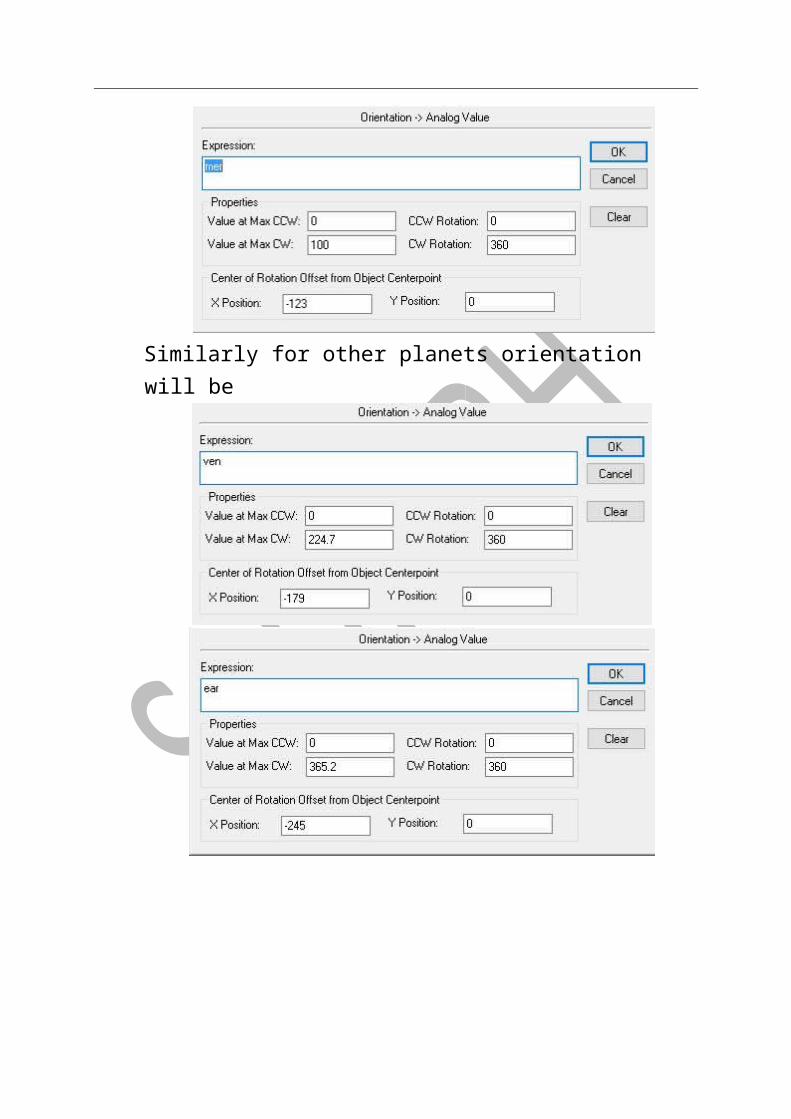
2. Now click on mercury image and click on orientation
)by using ( take a solar system picture 1-Step
Similarly for other planets orientation will be

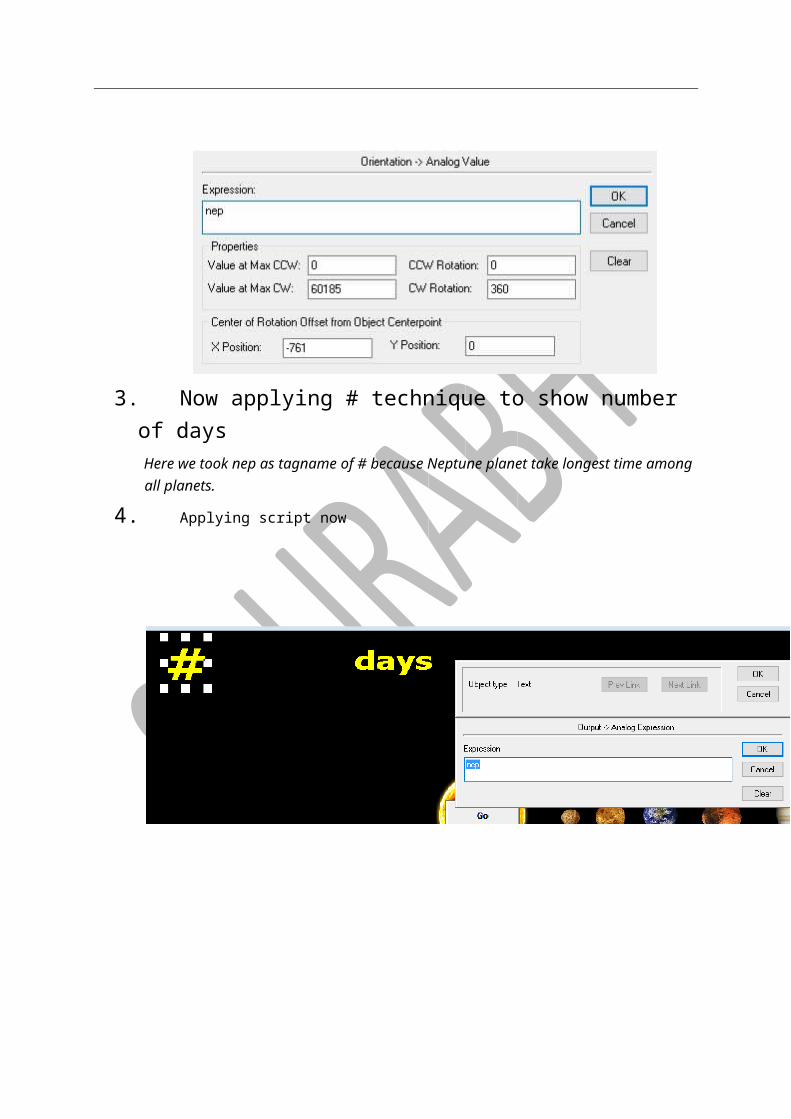
3. Now applying # technique to show number of days Here we took nep as tagname of # because Neptune planet take longest time among all planets.
4. Applying script now

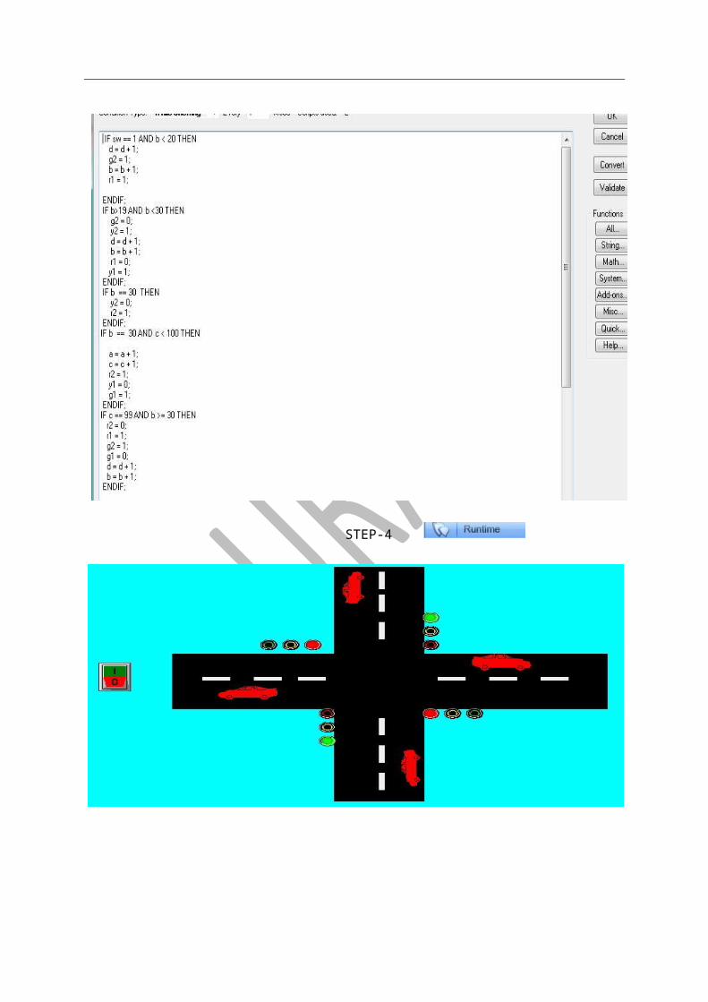
TASK-5 TRAFFIC SYSYEM WITH SINGLE CAR
STEP-1 TAKE A BUTTON, TAG NAME (SW)
STEP-2 MAKE A ROAD TRACK & TAKE A CAR
STEP-3 TAKE THREE LIGHTS
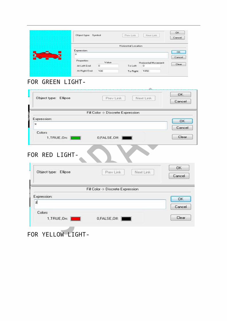
STEP-4 APPLY PROPERTY-
FOR CAR-
FOR GREEN LIGHT-
-Step
FOR RED LIGHT-
FOR YELLOW LIGHT-
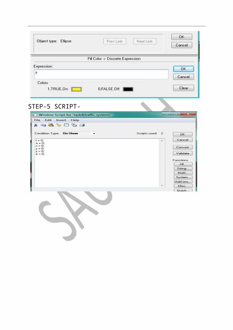
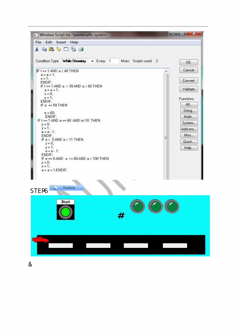
STEP-5 SCRIPT-
6-STEP

&
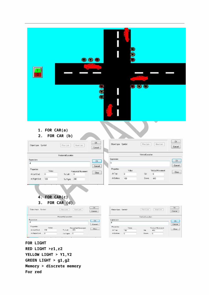
TASK-6 TRAFFIC SYSTEM FOR FOUR CARS
STEP-1 FIRST OF ALL WE CLICK ON THE WIZARD AND SELECT THE BUTTON > MOMENTRY AND DEFINE TAG NAME AS “SW” SAVE IN DISCRETE MEMORY AND CLOSE
DRAW THE ROAD AS LOOK LIKE BELOW AND SELECT THE CAR BY WIZARD > SYMBOL FACTORY > VEHICLES > CAR AND DEFINE THE TAG NAME FOR DIFFERENT PROPERTIES
CHOOSE THE LIGHT FOR TRAFFIC CONTROL BY WIZARD TOOL AS RED YELLOW AND GREEN LOOK LIKE AS BELOW
STEP-2 PROPERTIES ARE DEFINED AS FOLLOW
1. FOR CAR(a) 2. FOR CAR (b)
4. FOR CAR(c) 3. FOR CAR (d)
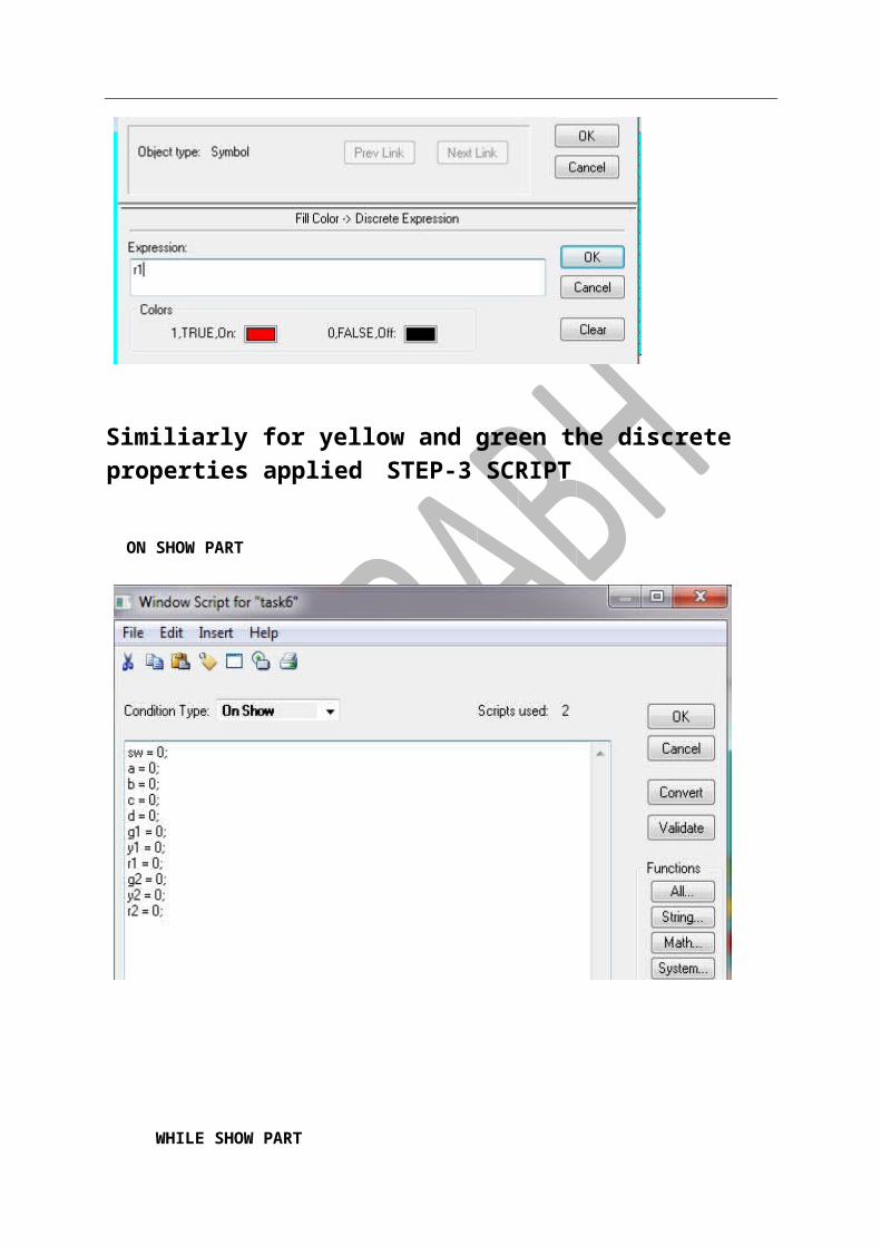
FOR LIGHT RED LIGHT >r1,r2 YELLOW LIGHT > Y1,Y2 GREEN LIGHT > g1,g2 Memory > discrete memory For red
Similiarly for yellow and green the discrete properties applied STEP-3 SCRIPT ON SHOW PART
WHILE SHOW PART

STEP-4
Recipe Management
Manufacturing industries build products according to repeatable procedures that use standardized quantities of raw materials. In essence, products are manufactured according to recipes. A recipe describes the raw materials, their quantities, and how they are combined to produce a finished product. In the most intuitive case, a bakery may follow a basic recipe that lists all ingredients and procedural steps to make cookies. (Recipe Manager is a supplementary component for the InTouch HMI that you can use to simplify the process of creating manufacturing recipes)
PROCESS-(GENRAL PROCESS TO MAKE AND SAVE FILE)
FILE PATHAND CONNECT BY NOW SCADA WORK
DESKTOP
FILE SAVE ON
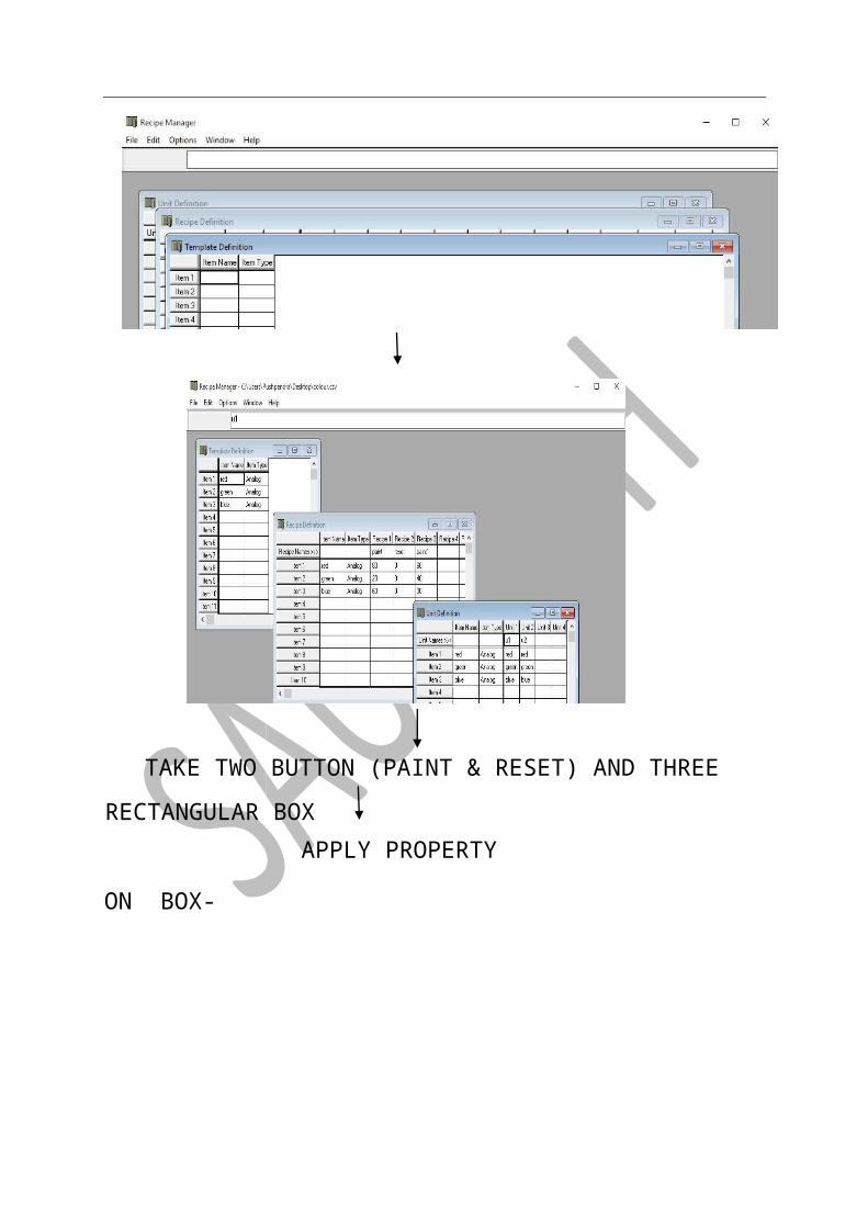
BL-ITEM2
RE-ITEM 1
U1-UNIT NAME DEFINATION
GO TO UNIT
0 ,0-RESET
100,200-REL RECIPE
FILL NAME OF
DEFINAIONGO TO RECIPE
ANALOG -ITEM TYPE
RED, BLUE -ITEM NAME
ITEM TYPENAME AND FILL ITEM
DEFINATIONTEMPLATION FIRST IS
DEFINATION OPENTHREE TYPE
NEW FILE MANAGER
RECIPE APPLICATION
FILLING THREE TANK)(-AS SHOWN
CLICK
CLICK CLICK
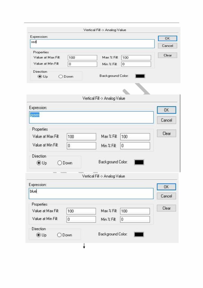
TAKE TWO BUTTON (PAINT & RESET) AND THREE RECTANGULAR
BOX APPLY PROPERTY

ON BOX-
Now double click on for paint button the click on Action (under Touch Pushbuttons). A new window
will pop-up then click on All (under functions in right lower corner
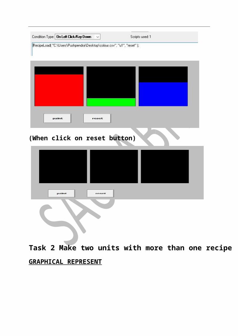
1. Now search for RecipeLoad and click on it
Above image is formate of recipe load. Now at place of FileName rename with file which is saved with its path and also with exact name and its extension. In unit name write unit as defined in recipe manager in unit definition and also for recipe name write same as defined in recipe definition.
Similarly do for reset button
(When click on reset button)
Task 2 Make two units with more than one recipe
GRAPHICAL REPRESENT
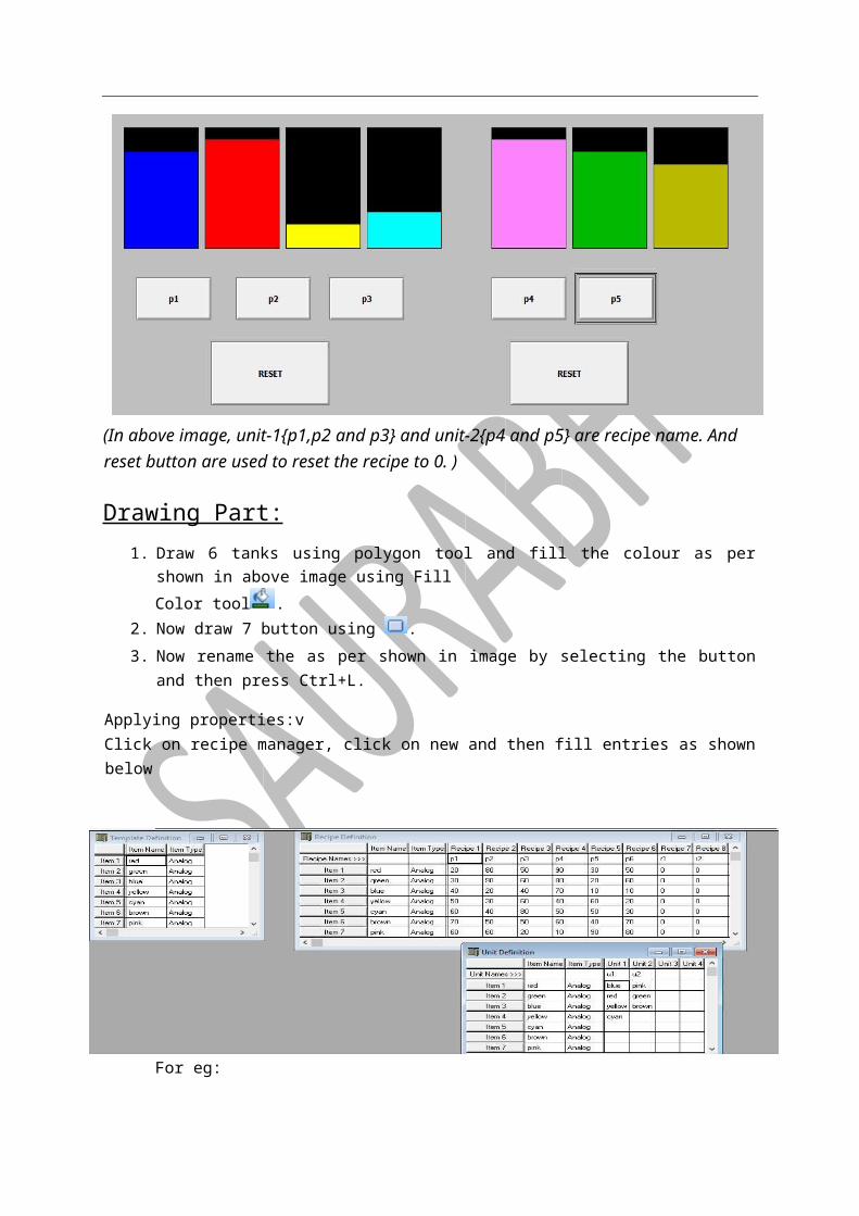
(In above image, unit-1{p1,p2 and p3} and unit-2{p4 and p5} are recipe name. And reset button are used to reset the recipe to 0. )
Drawing Part: 1. Draw 6 tanks using polygon tool and fill the colour as per shown in above image using Fill
Color tool . 2. Now draw 7 button using . 3. Now rename the as per shown in image by selecting the button and then press Ctrl+L.
Applying properties:v Click on recipe manager, click on new and then fill entries as shown below
For eg:

1. Double click on p1 button then click on action (under touch pushbuttons).
(*path may change according to pc to pc)
2. Similarly do with other buttons also.
3. Now simply run the project
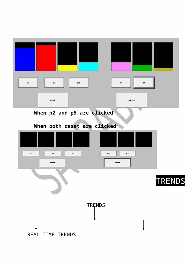
Output:(When p1 and p4 are clicked)
When p2 and p5 are clicked When both reset are clicked
TRENDS
(LIVE GRAPH) HISTORICAL TRENDS
(HISTORY PROCESS GRAPH)
REAL TIME TRENDS
TRENDS
TASK-1 REAL TIME TRENDS
Drawing part: 1. Firstly bring a slider from wizard. 2. Now draw a tank using rectangle tool.
3. Then with the help of real-time trend( ), draw a graph on window.
Applying properties: 1. Firstly define a tagname to vertical slider. And at time of deining Log data must be checked
and min and max value be place shown below.
2. Now define same tagname to the tank for the percent fill in the tank. 3. Then double click on the graph and then do as shown in below image
In above image time and sample are taken are equal as generally. In below pen, write the name of the tagname.
Initial State:
Final state:

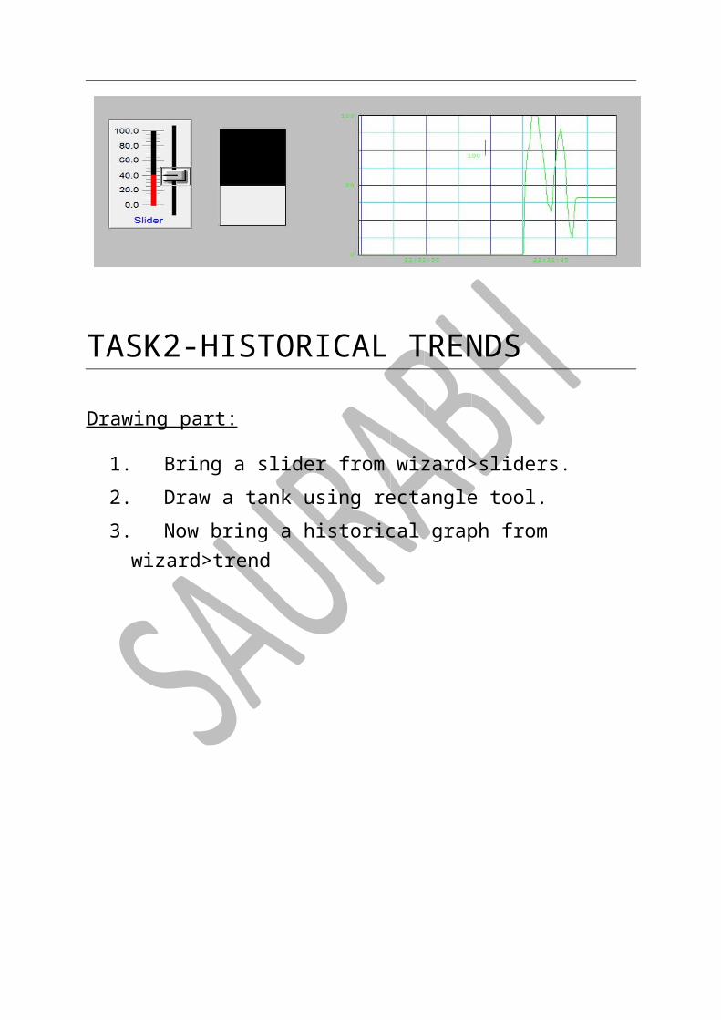
TASK2-HISTORICAL TRENDS
Drawing part:
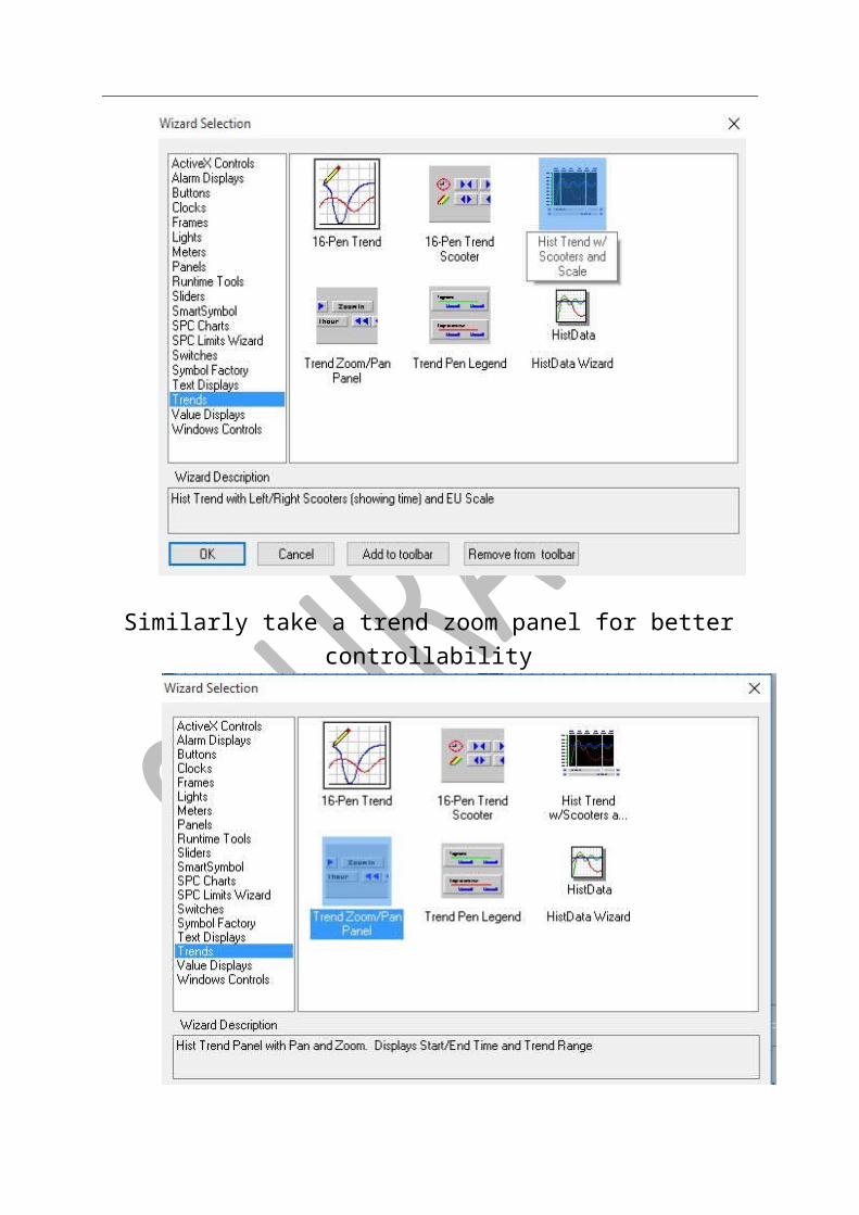
1. Bring a slider from wizard>sliders. 2. Draw a tank using rectangle tool. 3. Now bring a historical graph from wizard>trend
Similarly take a trend zoom panel for better controllability
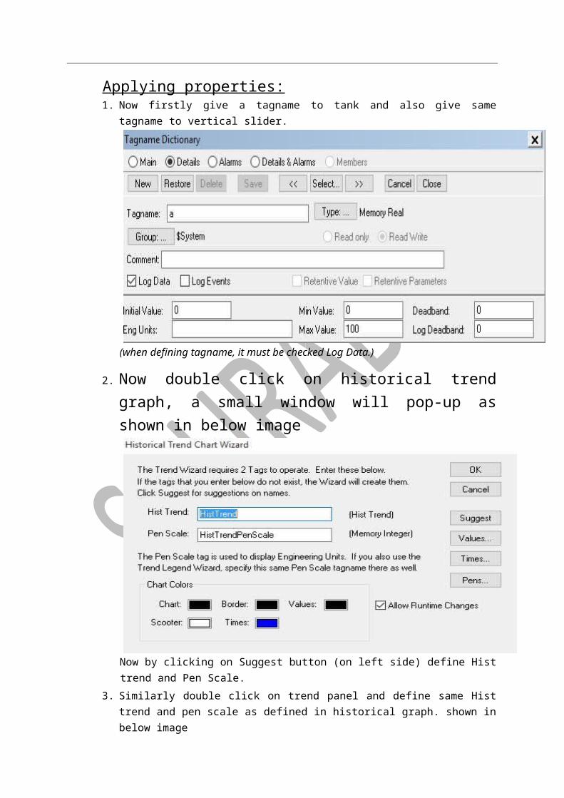
Applying properties: 1. Now firstly give a tagname to tank and also give same tagname to vertical slider.
(when defining tagname, it must be checked Log Data.)
2. Now double click on historical trend graph, a small window will pop-up as shown in below image
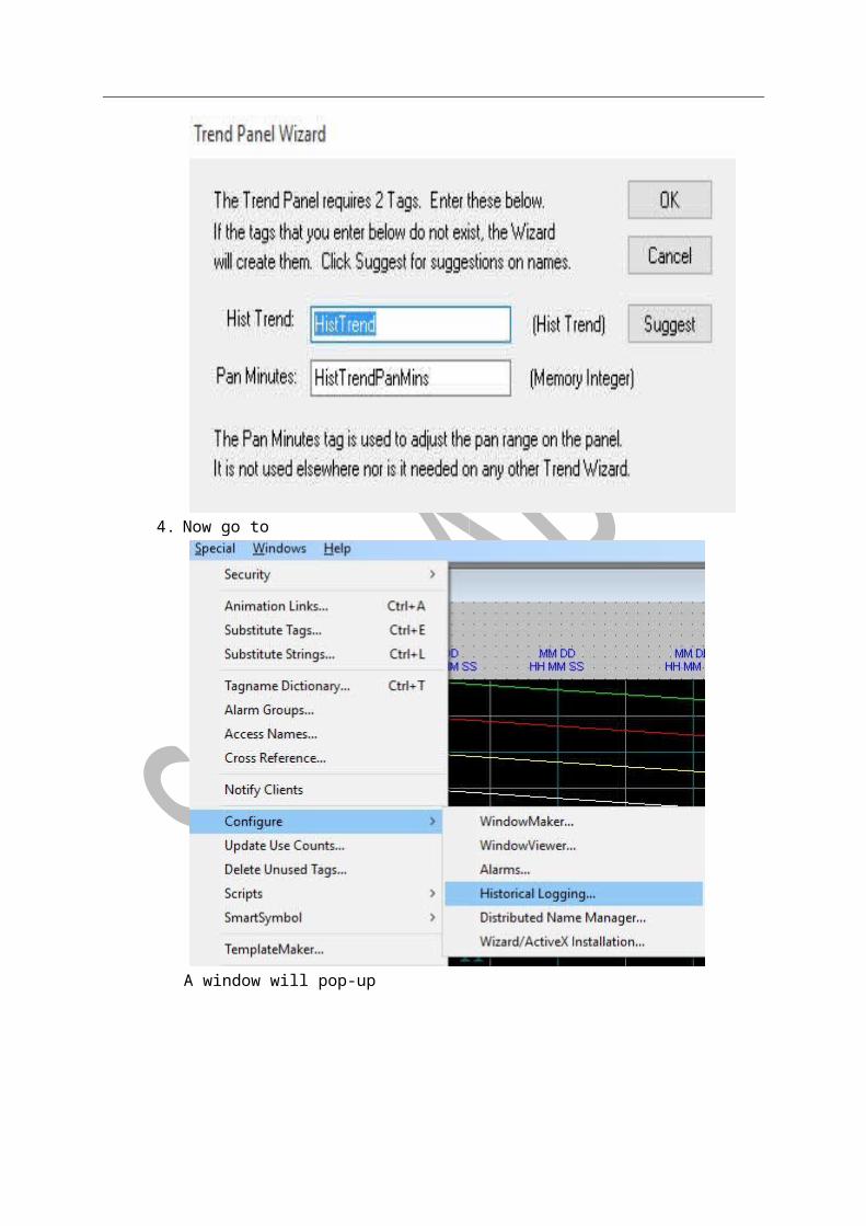
Now by clicking on Suggest button (on left side) define Hist trend and Pen Scale. 3. Similarly double click on trend panel and define same Hist trend and pen scale as defined
in historical graph. shown in below image
4. Now go to

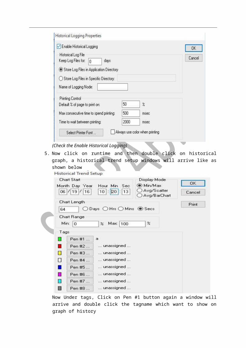
A window will pop-up
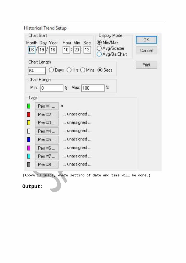
(Check the Enable Historical Logging) 5. Now click on runtime and then double click on historical graph, a historical trend setup
windows will arrive like as shown below
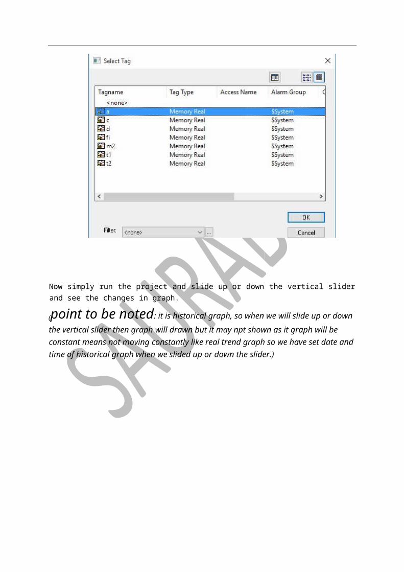
Now Under tags, Click on Pen #1 button again a window will arrive and double click the tagname which want to show on graph of history
Now simply run the project and slide up or down the vertical slider and see the changes in graph.
(point to be noted: it is historical graph, so when we will slide up or down the vertical slider then graph will drawn but it may npt shown as it graph will be constant means not moving constantly like real trend graph so we have set date and time of historical graph when we slided up or down the slider.)
(Above is image, where setting of date and time will be done.)
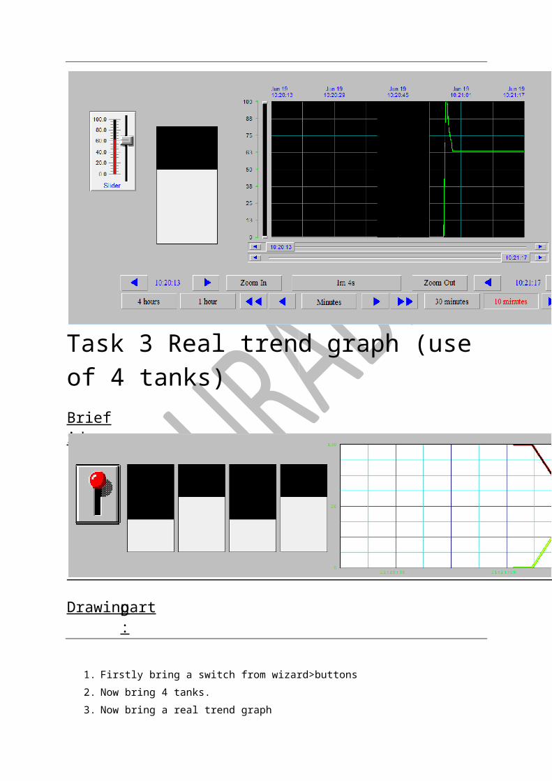
Output:

Task 3 Real trend graph (use of 4 tanks)
1. Firstly bring a switch from wizard>buttons
2. Now bring 4 tanks. 3. Now bring a real trend graph
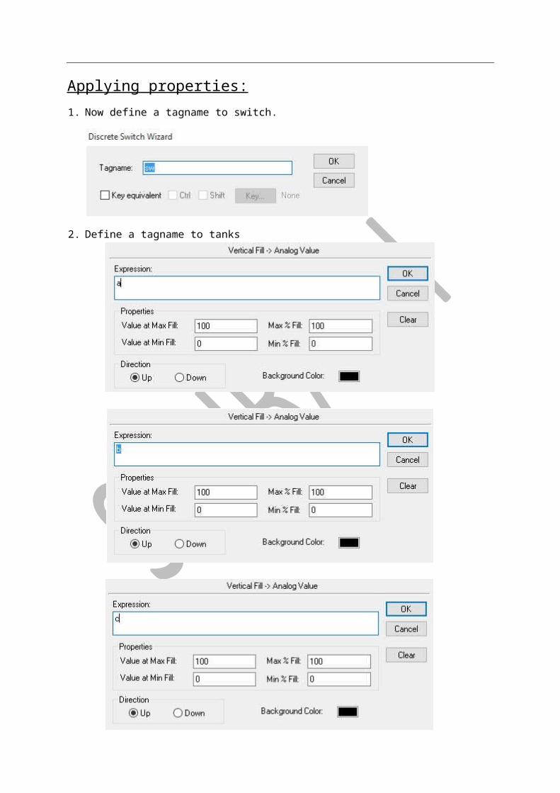
Applying properties: 1. Now define a tagname to switch.
part:Drawing
Brief idea:

2. Define a tagname to tanks
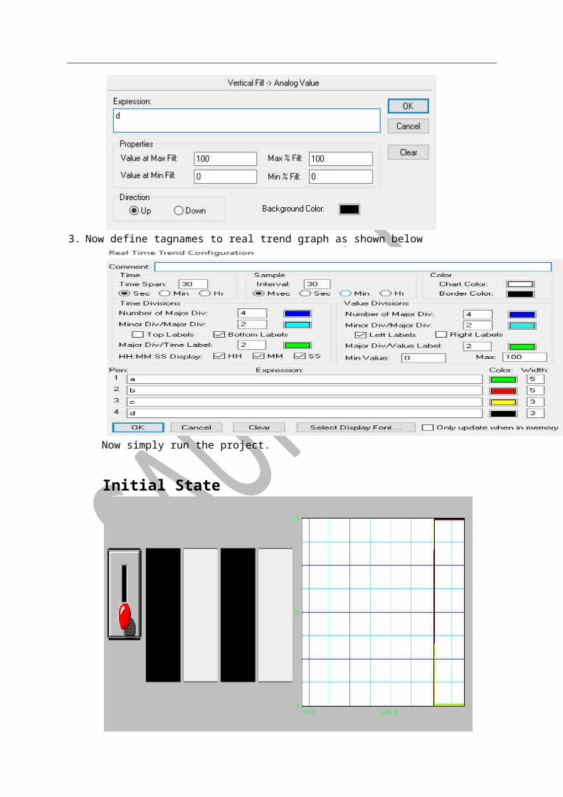
3. Now define tagnames to real trend graph as shown below
Now simply run the project.
Initial State

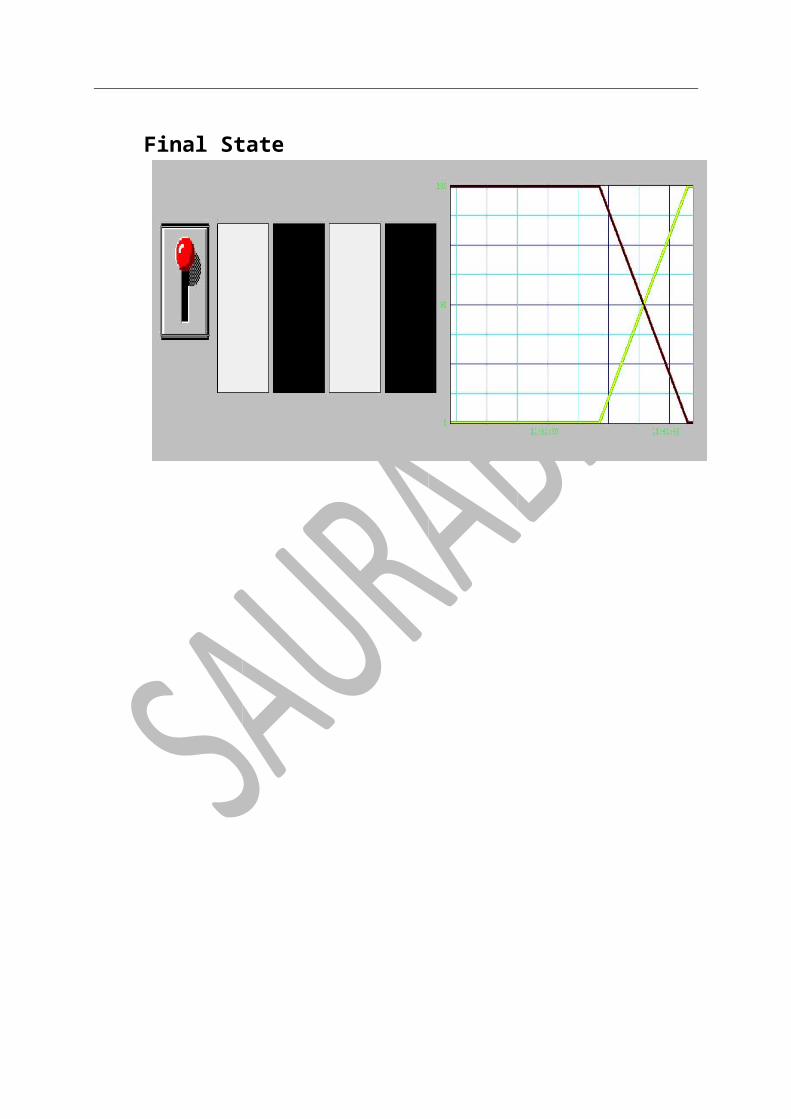
Final State
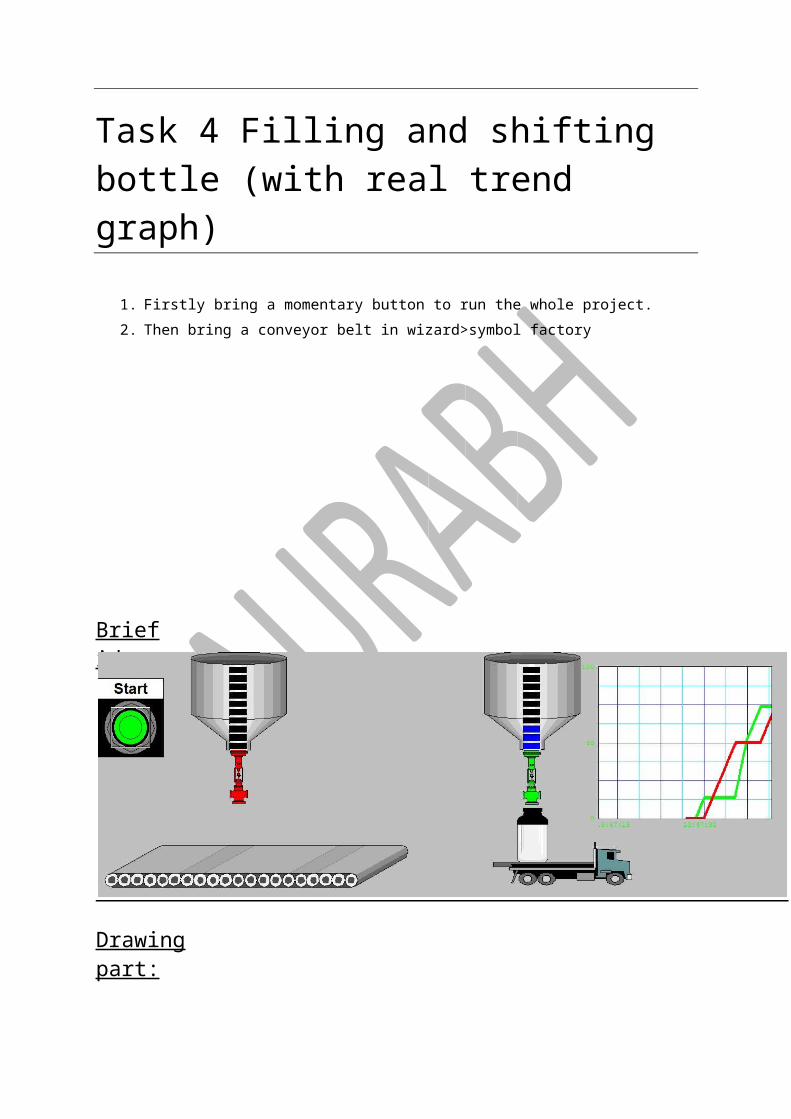
Task 4 Filling and shifting bottle (with real trend graph)
1. Firstly bring a momentary button to run the whole project. 2. Then bring a conveyor belt in wizard>symbol factory
Drawing part:
Brief idea:

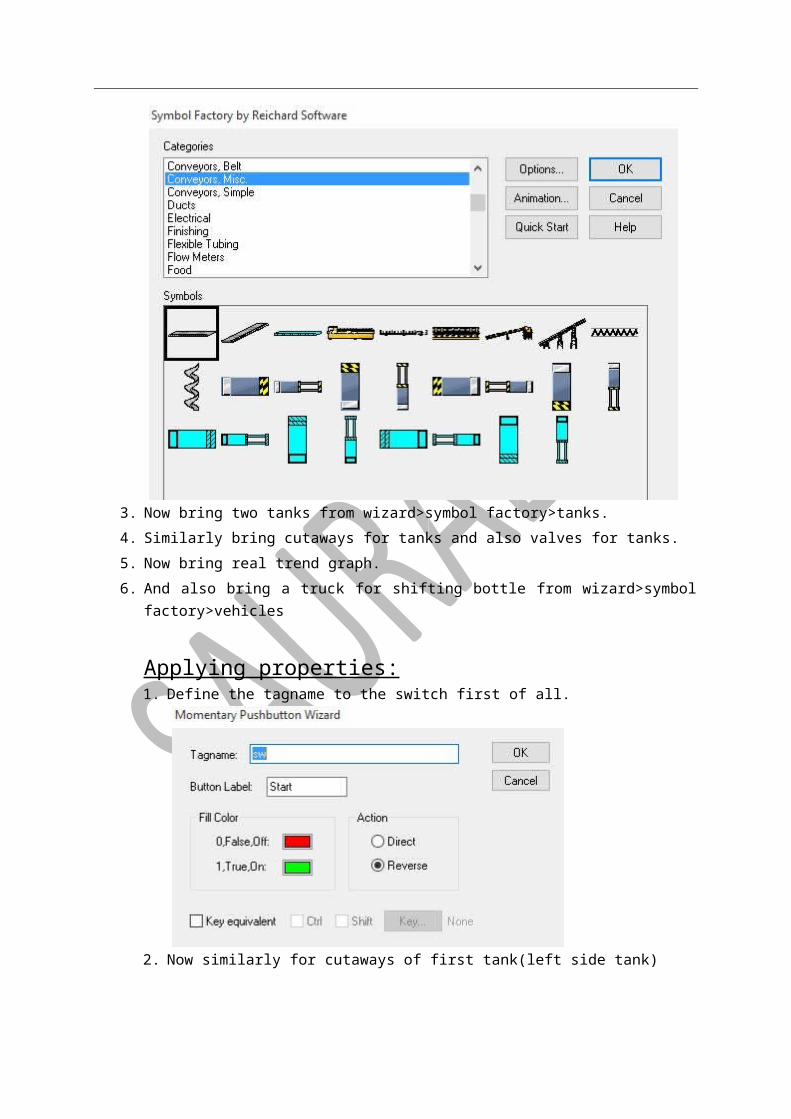
3. Now bring two tanks from wizard>symbol factory>tanks. 4. Similarly bring cutaways for tanks and also valves for tanks. 5. Now bring real trend graph. 6. And also bring a truck for shifting bottle from wizard>symbol factory>vehicles
Applying properties: 1. Define the tagname to the switch first of all.
2. Now similarly for cutaways of first tank(left side tank)
Cutaway from second tank (right side tank)
3. Now for valve of tank 1 then
Similarly for valve of tank 2
4. Now movement of truck will be
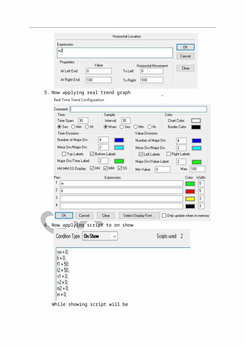
5. Now applying real trend graph
6. Now applying script to on show
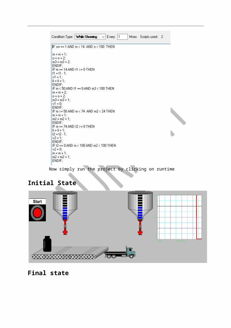
While showing script will be
Now simply run the project by clicking on runtime
Initial State
Final state
ALARMS
ALARMS ARE USED FOR SAFTY PURPOSE
STATUS- FOUR TYPE OF STATUS ARE USED –
I. LOLO STATUS II. LO STATUS III. HI STATUS IV. HI HI STATUS
TASK-1 ALARM USED BY SLIDER
STEP-1 TAKING A SLIDER (TAG NAME-S1) & FOUR CIRCULAR LIGHTS FROM WIZARD
STEP-2 TAKE A RECTANGAL (AS A TANK)
STEP-3 TAKE A BUTTON (FOR ACHKNOWLEDGEMENT)& ALARM DISPLAY
PROCESS FOR ALARM-
PROCESS FOR ACHKOWLEDEMENT-
LIGHTFOR ALL PROCESS
S1.LO ETC
-EXPRESSIONWRITE THE
IN LIGHT
DOWBLE CLICK
SAVE
&95-HIHI
80-HI
40-LO
20-LOLO
VALUETAKE THE
VALUEALARM GO TO THE
ALARMSDETAILS & CLICK IN
TAG NAME (S1)RECTANGULAR BOX SLIDER/ DOUBLE CLICK
OK NAME
WRITE A TAG
ACKFUNCTION CHOOSE
ALLFUNCTION GO TO
ACTIONCLICK TO
BOTTONPUSH TOUCH
ACKWRITE A
BUTTONTAKE A
DOUBLE CLICK CTRL+L
STEP-
NOTE= THE PROCESS OF ALARM ARE SAME FOR SCRIPT.
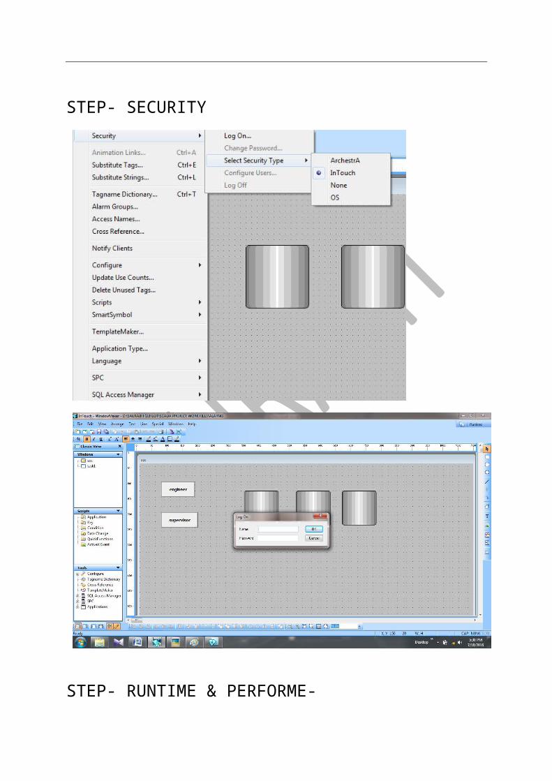
SECURITY
Security property used in SCADA for secure and work according to given access level
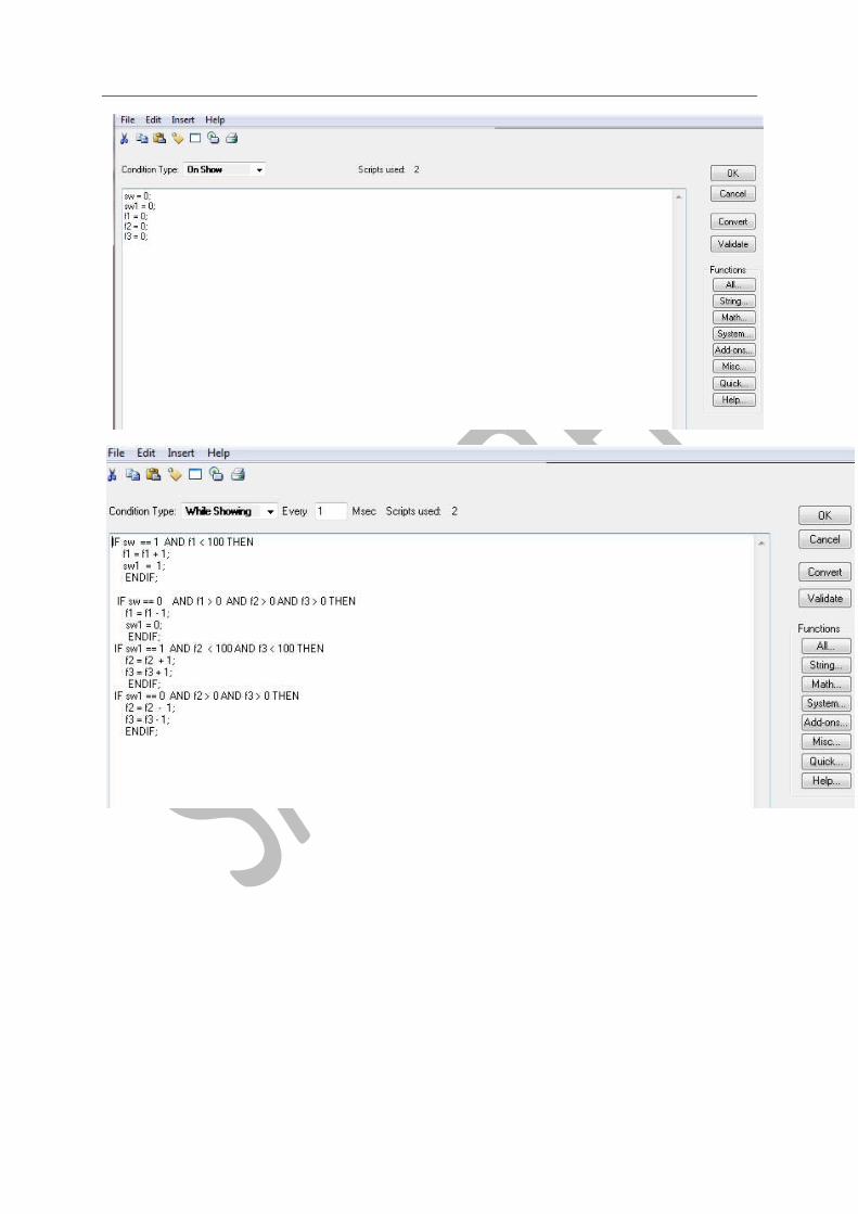
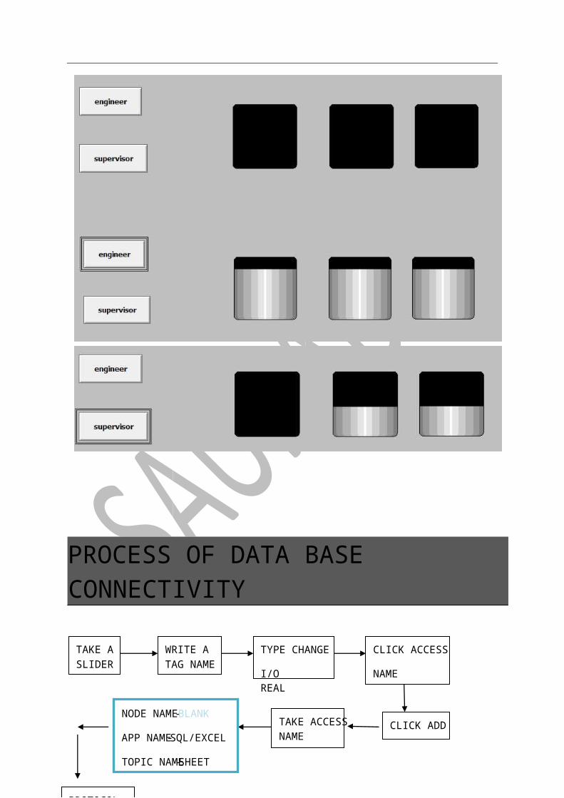
Process of security-(engineer control three tank and supervisor control two tank and engineer can work of supervisor)
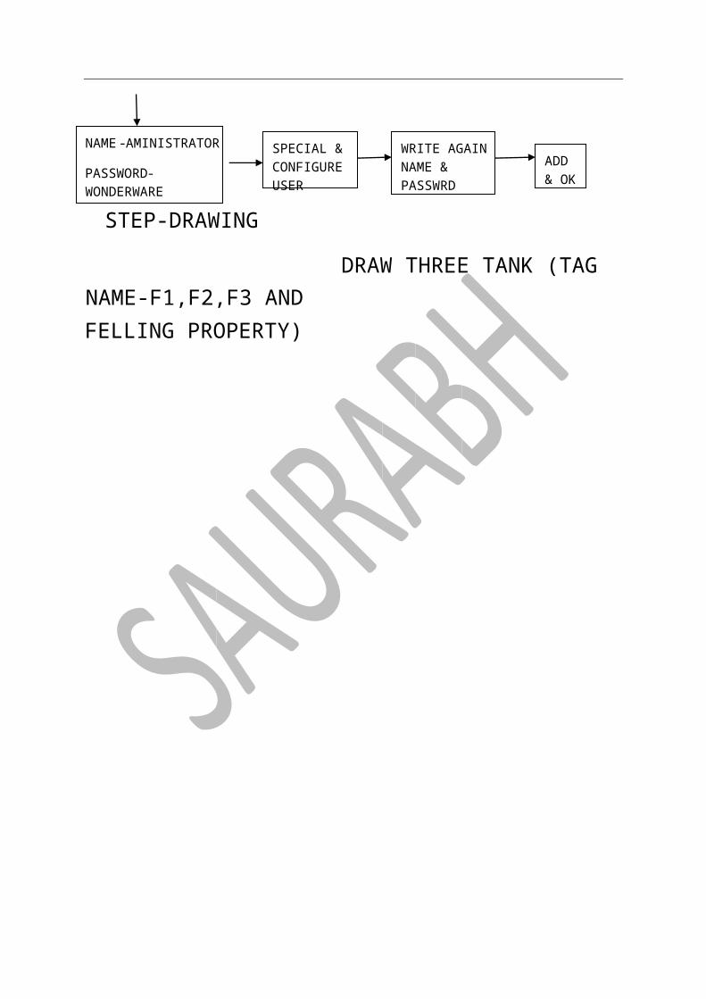
STEP-DRAWING
DRAW THREE TANK (TAG NAME-F1,F2,F3 AND FELLING PROPERTY)
PASSWORDENTER NAME & LOG ON SECURITY SPECIAL
TYPE INTOUCHSECURITY SELECT SECURITY SPECIAL
BUTTON
TAKE TWO
SUPERVISOR
ENGINEER
ADMIN
B
7777
8888
ACCESS LEAVEL 9999 –ACCESS LEAVEL
& OKADD
PASSWRDNAME & WRITE AGAIN
USERCONFIGURE SPECIAL &
WONDERWARE-PASSWORD
AMINISTRATOR -NAME
STEP-SCRIPT
STEP- SECURITY
STEP- RUNTIME & PERFORME-
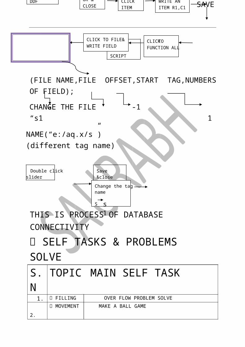
PROCESS OF DATA BASE CONNECTIVITY
GO TO WINDOW SCRIPT
CLICK TO FUNCTION ALL
CLICK TO FILE& WRITE FIELD
ITEM R1,C1WRITE AN
ITEMCLICK
CLOSEOK & DDF
-PROTOCOL
SHEET-TOPIC NAME
SQL/EXCEL-APP NAME
BLANK-NODE NAME
NAMETAKE ACCESS CLICK ADD
NAME
CLICK ACCESS
I/O REAL
TYPE CHANGE TAG NAME
WRITE A SLIDER
TAKE A
SAVE
(FILE NAME,FILE OFFSET,START TAG,NUMBERS OF FIELD);
CHANGE THE FILE -1 “s1” 1
NAME(“e:/aq.x/s”) (different tag name)
Double click slider Save &close
THIS IS PROCESS OF DATABASE CONNECTIVITY
SELF TASKS & PROBLEMS SOLVE S.N TOPIC MAIN SELF TASK 1. FILLING OVER FLOW PROBLEM SOLVE 2. MOVEMENT MAKE A BALL GAME 3. VISIBILITY,
ORINTATION, MOVEMENT
MAKING A PLANT WHICH USES LIFTING, PAKING & TRAVELLING
4. PLANT NUCLEAR & THERMEAL PLANT WORKING SHOW 5. SCRIPT PROBLEM SOLVES BY SCRIPT
NOTE- SOME MAIN TASK HAVE MANY CONTAIN SO EXPLAIN ONLY SMALLER TASK
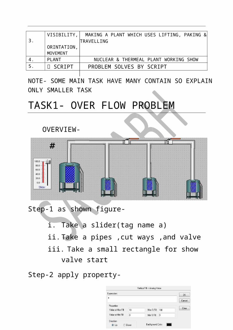
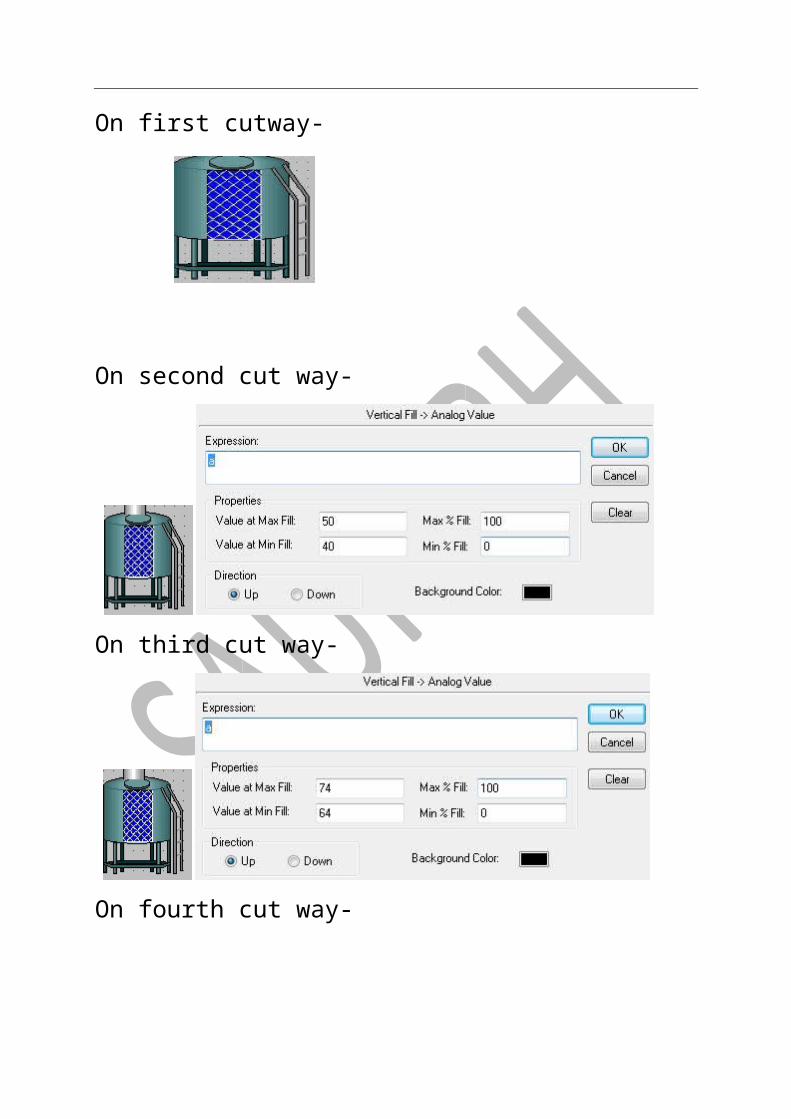
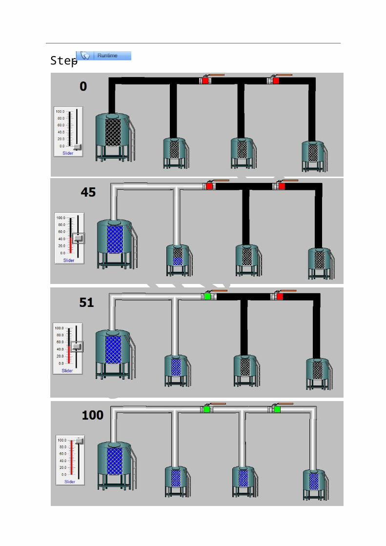
TASK1- OVER FLOW PROBLEM
OVERVIEW-
s1S
nameChange the tag

Step-1 as shown figure-
i. Take a slider(tag name a) ii. Take a pipes ,cut ways ,and valve iii. Take a small rectangle for show valve start
Step-2 apply property-
On first cutway-
On second cut way-
On third cut way-
On fourth cut way-
On first valve-
On second valve-
In pipes property according to tank filling and valve activate.
-Step

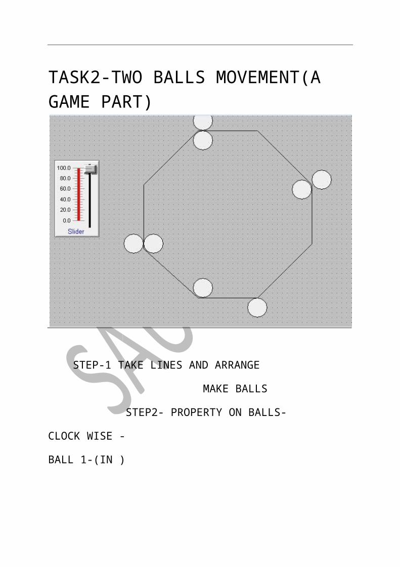
TASK2-TWO BALLS MOVEMENT(A GAME PART)
STEP-1 TAKE LINES AND ARRANGE
MAKE BALLS
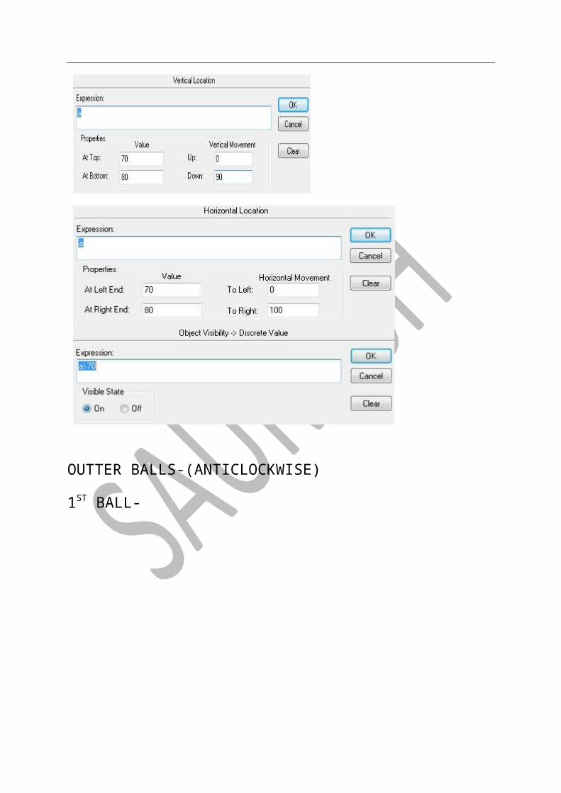
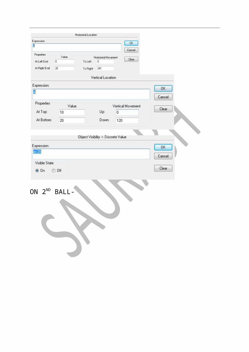
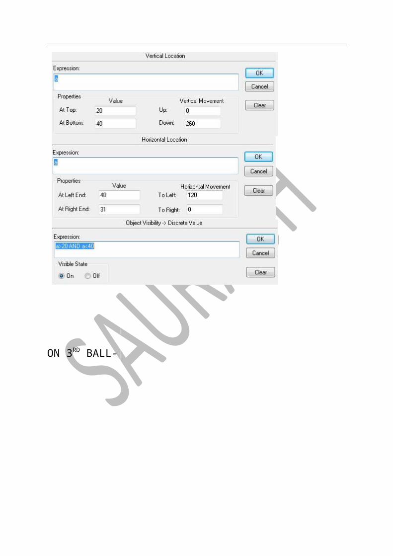
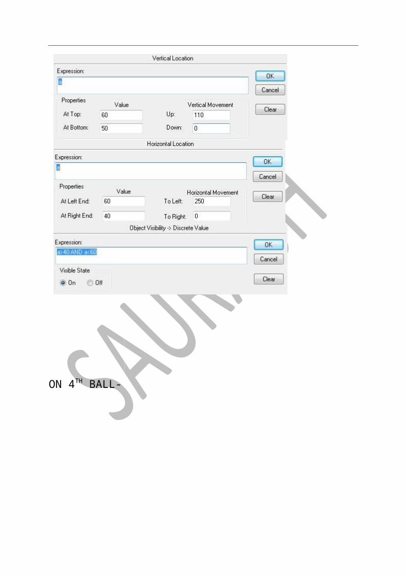
STEP2- PROPERTY ON BALLS-
CLOCK WISE -
BALL 1-(IN )

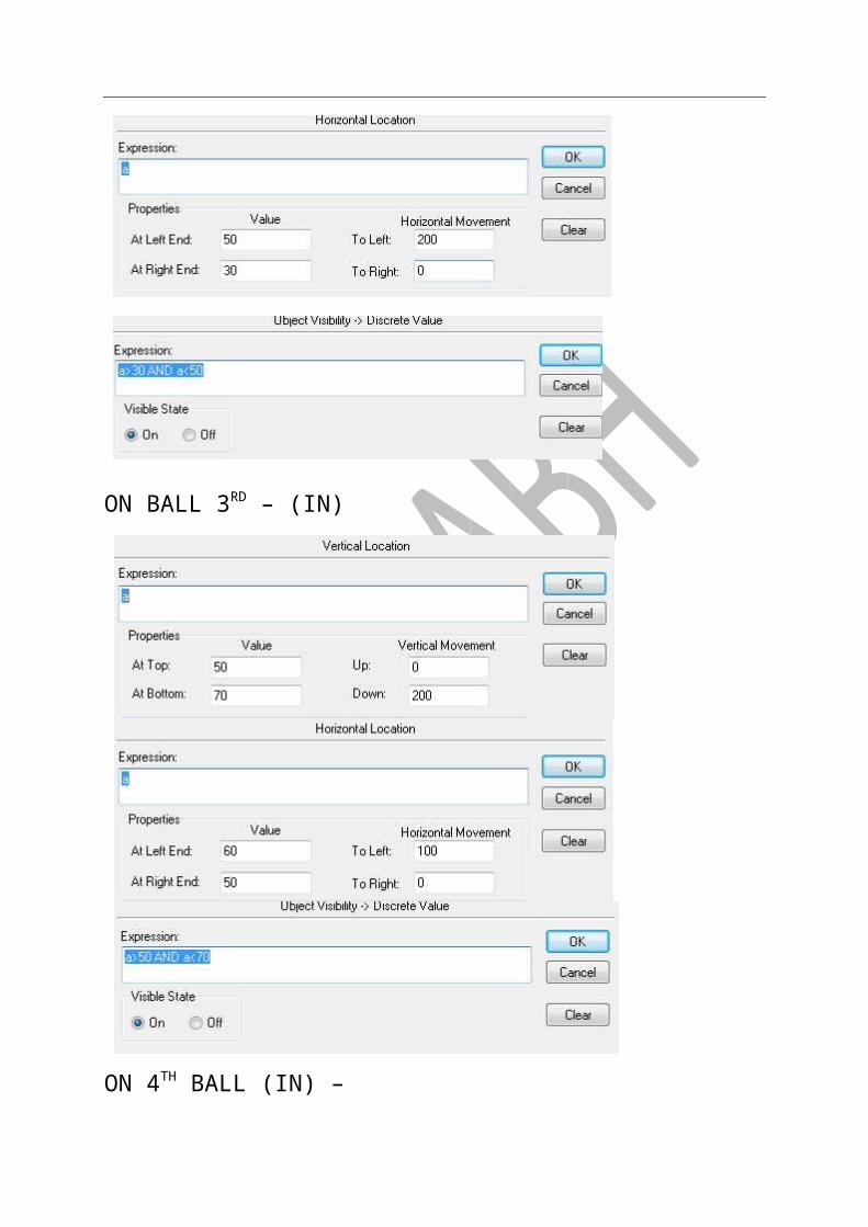
ON BALL-2ND (IN)

ON BALL 3RD – (IN)
ON 4TH BALL (IN) –

OUTTER BALLS-(ANTICLOCKWISE)
1ST BALL-

ON 2ND BALL-
ON 3RD BALL-

ON 4TH BALL-
-STEP
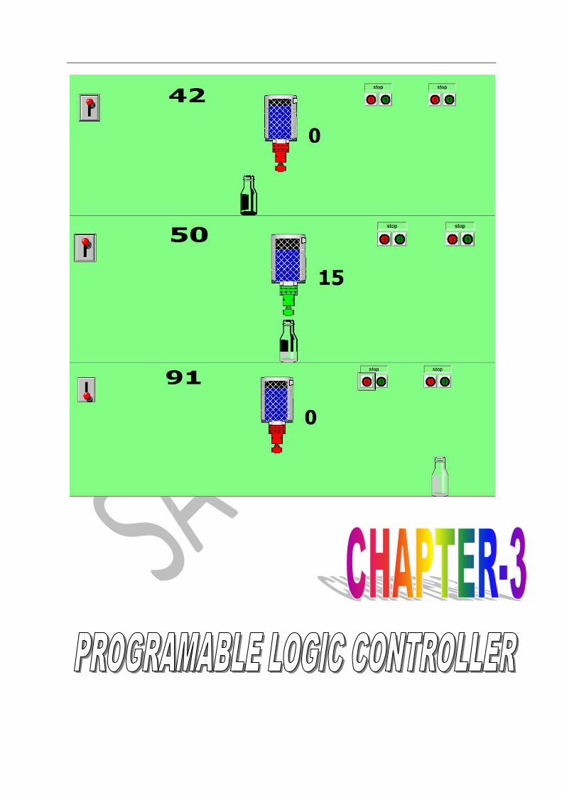
PROBLEM SOLVING TASK TASK-1 BOTEL FILLING PROCESS OF PLANT WITH AUTOMATED
AND MANUAL SYSTEM
SPECIALITY OF TASK- AFTER FILLING BOTEL TANK WILL AUTOMATIC FILL AGAIN
OVERVIEW OF TASK-
STEP1- TAKE MAIN SWITCH (TAG NAME t)
TAKE A TRANSPERENT BOTEL-
HORIZONTEL-n
VERTICAL-b
Step 2- tank cut way-(vertical property-a)
Valve discrete value =v (fill colored)
Step3- takes two switches for manually work(tag name j & k)
Step4- script-
Step-
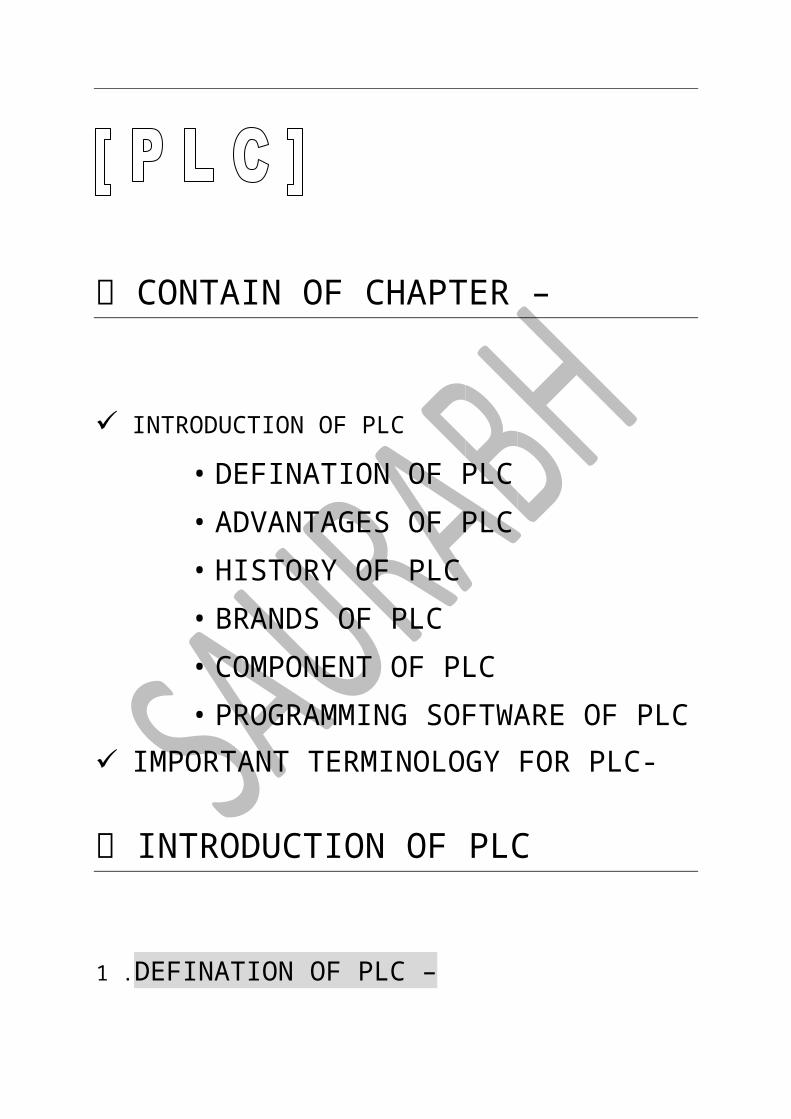
CONTAIN OF CHAPTER –
INTRODUCTION OF PLC • DEFINATION OF PLC • ADVANTAGES OF PLC • HISTORY OF PLC • BRANDS OF PLC • COMPONENT OF PLC • PROGRAMMING SOFTWARE OF PLC
IMPORTANT TERMINOLOGY FOR PLC- INTRODUCTION OF PLC
1 .DEFINATION OF PLC –

• ADVANTAGES OF PLC-
• HISTORY OF PLC-
• BRANDS OF PLC-
IMAGES OF LOGO-

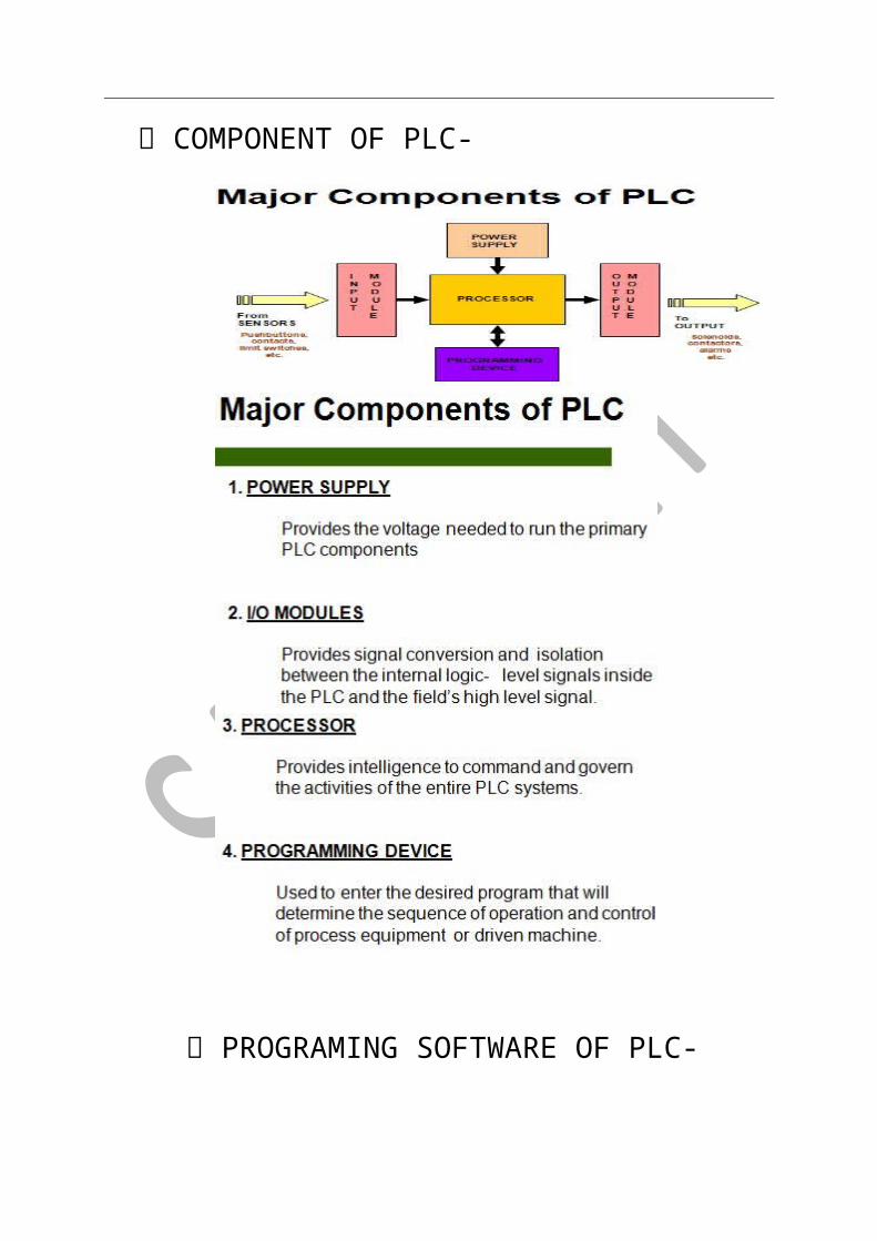
COMPONENT OF PLC-
PROGRAMING SOFTWARE OF PLC-
SOME IMPORTANT TERMINOLGY CATLOG NUMBER /MODEL NUMBER EXP. (ALLEN BRADLY) PLC-
DIFFERENCE B/W PLC & DCS –
PLC DCS
ITS WORK ON GUI SYSTEM ITS NOT WORK ON GUI SYSTEM
ITS WORK 0.2µC ITS WORK ON 0.5µC
MAINTENANCE COST IS LOW MAINTENCE COST IS HIGH WORK ON REAL TIME APPLICATION
NOT WORK ON REAL TIME APPLICATION
What is ladder logic programming? Ladder logic is a programming language that represents a program by a graphical diagram based on the circuit diagrams of relay-based logic hardware. It is primarily used to develop software for Programmable Logic Controllers (PLCs) used in industrial control applications
Points to Remember:
a. Whenever switches are to perform on operation, then the switches should be connected in parallel.
b. Whenever switches are to perform off operation, then switches should be connected in series.
c. The below table is very important as per hardware buttons used on PLC kit. By using the below table NO type button can be converted to NC type button and vice-versa.
Hardware Software Button require on PLC
NO NO NO NC NC NO NO NC NC NC NO NC
Key of table: NO- Normally open NC- Normally closed.
d. Switches can be interchange between NO and NC by using XIC and XIO respectively. Here XIC stands for examine If Close XIO stands for examine If Open
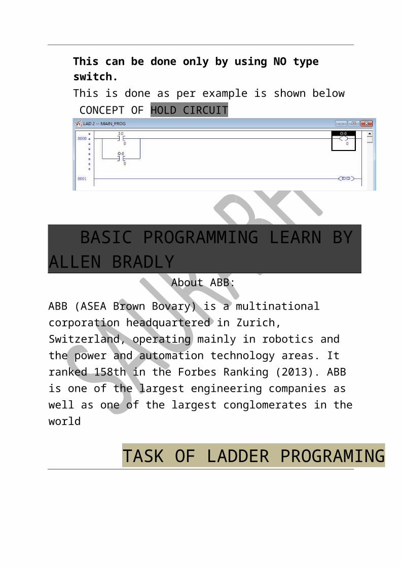
e. Whenever there is a requirement to hold a signal (for eg. Turn on of motor) then hold circuit is used. This can be done only by using NO type switch. This is done as per example is shown below CONCEPT OF HOLD CIRCUIT
BASIC PROGRAMMING LEARN BY ALLEN BRADLY About ABB:
ABB (ASEA Brown Bovary) is a multinational corporation headquartered in Zurich, Switzerland, operating mainly in robotics
and the power and automation technology areas. It ranked 158th in the Forbes Ranking (2013). ABB is one of the largest engineering companies as well as one of the largest conglomerates in the world
TASK OF LADDER PROGRAMING
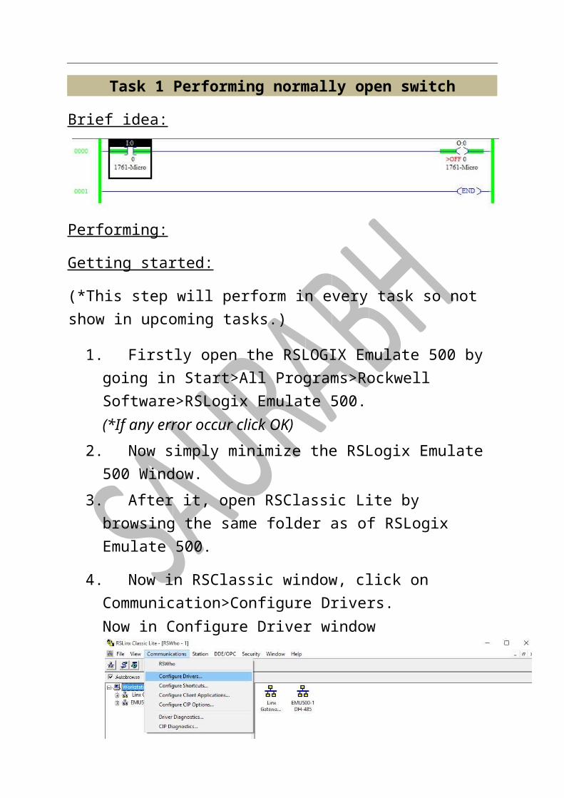
Task 1 Performing normally open switch
Brief idea:
Performing:
Getting started:
(*This step will perform in every task so not show in upcoming tasks.)
1. Firstly open the RSLOGIX Emulate 500 by going in Start>All Programs>Rockwell Software>RSLogix Emulate 500. (*If any error occur click OK)
2. Now simply minimize the RSLogix Emulate 500 Window. 3. After it, open RSClassic Lite by browsing the same folder as of
RSLogix Emulate 500.
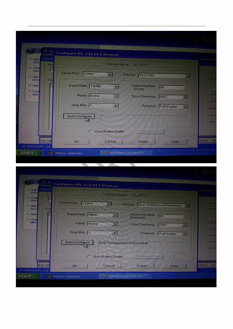
4. Now in RSClassic window, click on Communication>Configure Drivers. Now in Configure Driver window
If program will be performed by Allen Bradley PLC then select the PLC name or if program are performed using emulator then select as below option is selected.
(*Remember if any device is running then click on stop and delete the device and then perform above task.) After selecting the device then click on Add New then click twice OK. Then click on Close and then minimize the RSClassic window also. For running on PLC kit then steps are as follow:


5. Now after performing this, run the RSLogix Micro English again this will be found in same
directory.
Drawing rung:
1. Click on File > New and then select the PLC which we have to perform Ladder for. In our case, PLC is Build 1761 MicroLogix 1000.
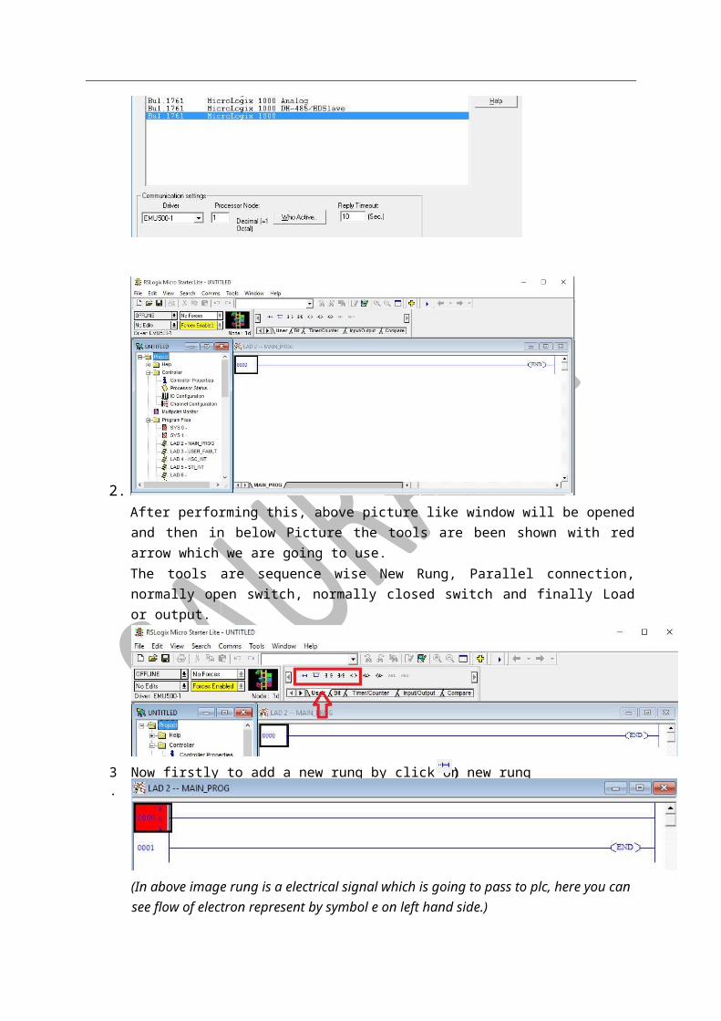
2. After performing this, above picture like window will be opened and then in below Picture the tools are been shown with red arrow which we are going to use. The tools are sequence wise New Rung, Parallel connection, normally open switch, normally closed switch and finally Load or output.
(In above image rung is a electrical signal which is going to pass to plc, here you can see flow of electron represent by symbol e on left hand side.)
4. Now simply put the normally open switch and the ouput or load by using respective buttons.
).Now firstly to add a new rung by click on new rung sign ( 3.
Now at place of question mark sign, double click to label them. Label the normally open switch as”I: 0.0/0” and label the output switch as “O: 0.0/0”. (Here I stand for input 0 stands for Slot Number again 0 stands for Word number and final 0 stands for Bit Number) So Syntax of labeling will be: Filename: SlotNumber.WordNumber/BitNumber After labeling
If you are using emulator rather than a PLC then only follow these steps:
a.

b.
5. Now go near Offline arrow and click on it
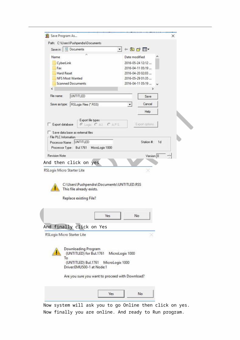
Click on save

And then click on yes
And finally click on Yes
Now system will ask you to go Online then click on yes. Now finally you are online. And ready to Run program.

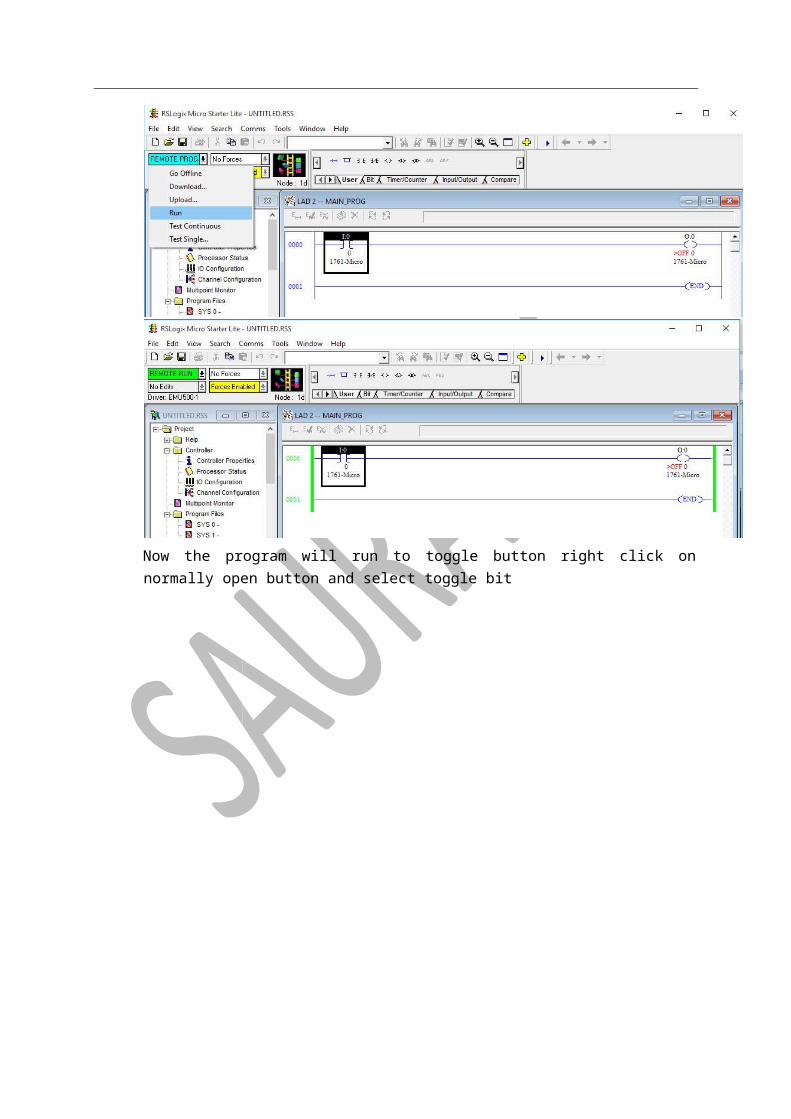
Now the program will run to toggle button right click on normally open button and select toggle bit

Final Result:
To draw normally closed circuit the circuit will be as shown below and procedure will as shown above
Task 2 Performing operation as Logic Gates
X Y OR AND NOR NAND Ex-OR Ex-NOR 0 0 0 0 1 1 0 1 0 1 1 0 0 1 1 0 1 0 1 0 0 1 1 0 1 1 1 1 0 0 0 1
Drawing rung: 1. Click on File > New and then select the PLC which we have to perform Ladder for. In our
case, PLC is Build 1761 MicroLogix 1000.

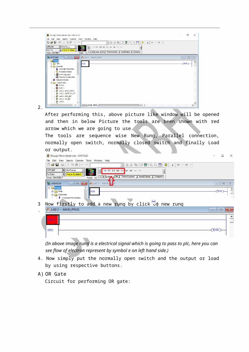
2. After performing this, above picture like window will be opened and then in below Picture the tools are been shown with red arrow which we are going to use. The tools are sequence wise New Rung, Parallel connection, normally open switch, normally closed switch and finally Load or output.
(In above image rung is a electrical signal which is going to pass to plc, here you can see flow of electron represent by symbol e on left hand side.)
4. Now simply put the normally open switch and the output or load by using respective buttons.
A) OR Gate Circuit for performing OR gate:
Now download the project in emulator and then run the project. The outputs are shown below:
).Now firstly to add a new rung by click on new rung sign ( 3.
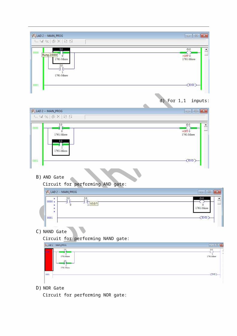
d) For 0,0 inputs:
b)
For 0,1 inputs:
c)
For 1,0 inputs:
d)
For 1,1 inputs:

B) AND Gate Circuit for performing AND gate:
C) NAND Gate Circuit for performing NAND gate:
D) NOR Gate Circuit for performing NOR gate:
E) Ex-OR Gate Circuit diagram for performing Ex-OR gate
F) Ex-NOR Gate
Task 3
Using 2 No and 2 Nc buttons, by clicking on 1- No then light will be on then turn off button is 2 – Nc and 1 – Nc button will glow the light and 2 – No button will turn off the light.
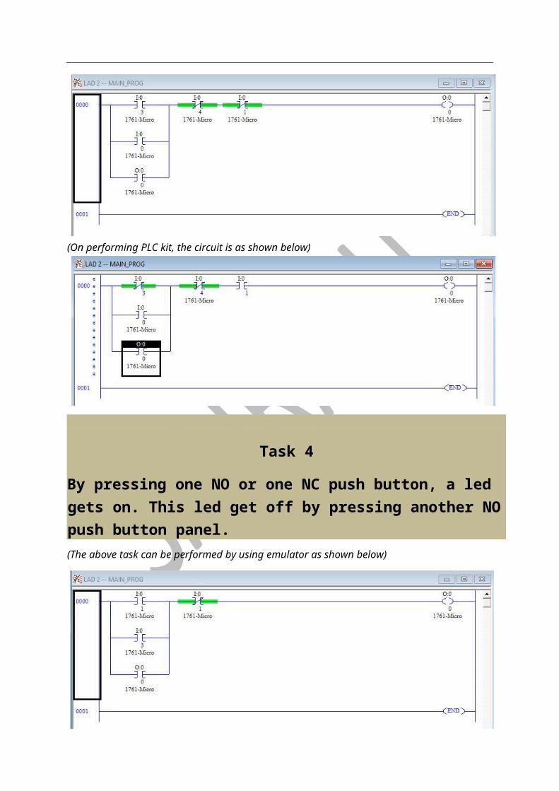
(On performing emulator circuit will be drawn as shown in below image)
(On performing PLC kit, the circuit is as shown below)
Task 4
By pressing one NO or one NC push button, a led gets on. This led get off by pressing another NO push button panel. (The above task can be performed by using emulator as shown below)
(The above task can be performed by using PLC Kit as shown in below image)
Task 4(a)
A motor get on from any of the 3 location by pressing No push buttons on the panel. This motor gets off by pressing Nc push button on the panel.

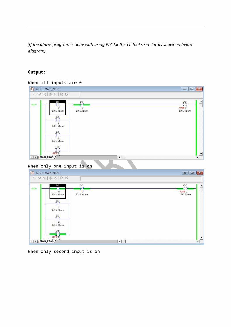
(Below diagram of circuit of program is drawn without using PLC kit i.e with RSLogix Emulator 500)
(If the above program is done with using PLC kit then it looks similar as shown in below diagram)
Output:
When all inputs are 0
When only one input is on

When only second input is on
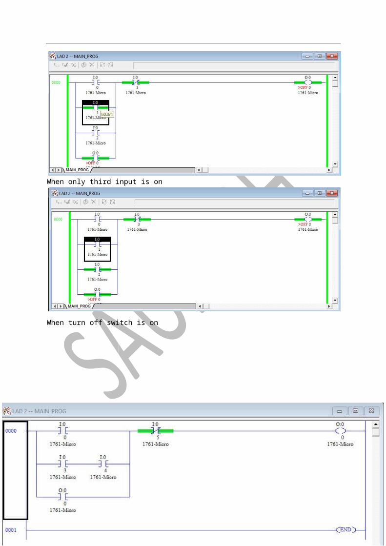
When only third input is on
When turn off switch is on
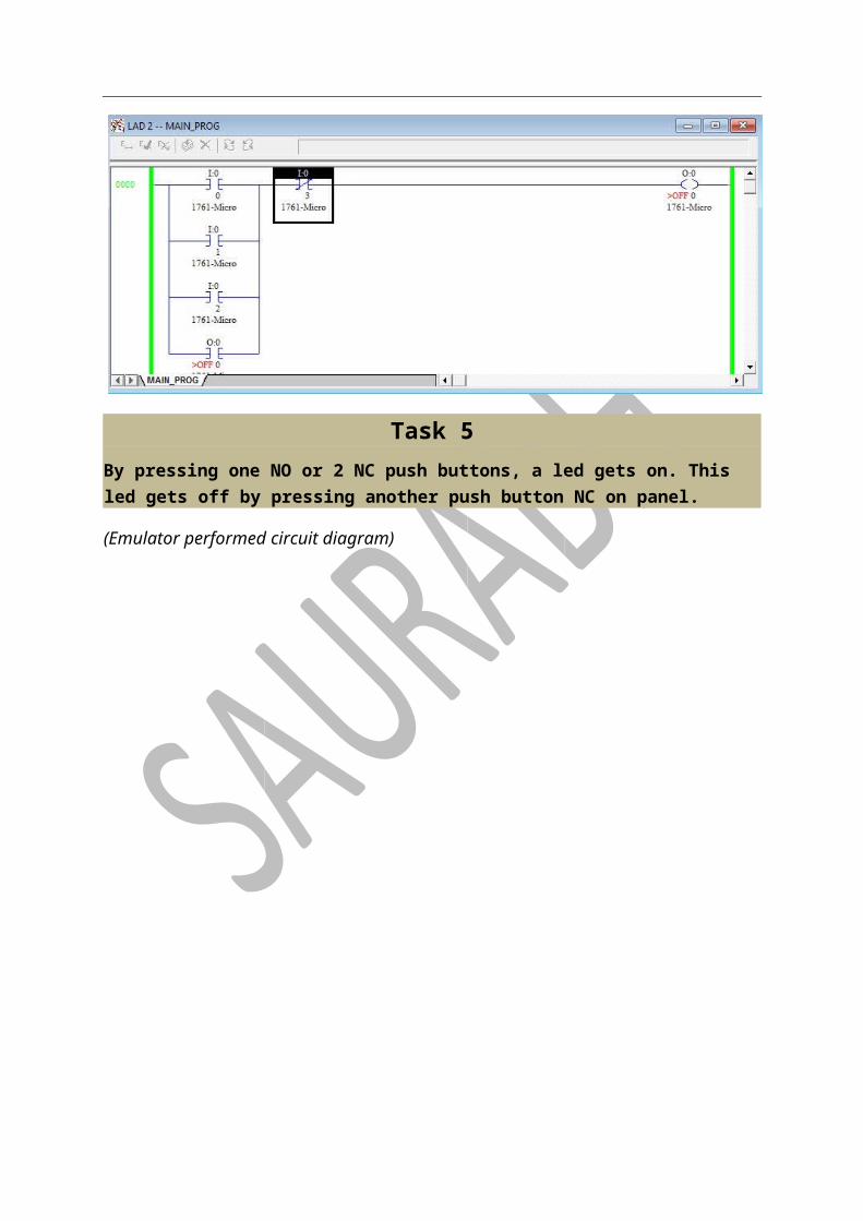
Task 5 By pressing one NO or 2 NC push buttons, a led gets on. This led gets off by pressing another push button NC on panel.
(Emulator performed circuit diagram)

(PLC kit performed circuit diagram)
Task 6 By pressing any one of the NC push button led gets on and by pressing any one NO from 2
NO button led gets off.
(When performing on emulator then circuit diagram as shown below)
(On performing on PLC kit then circuit will be)
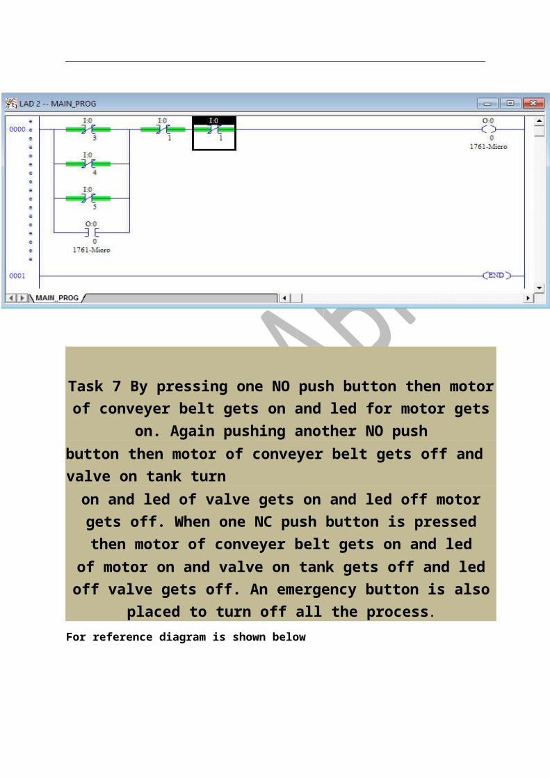
Task 7 By pressing one NO push button then motor of conveyer belt gets on and led for motor gets on. Again pushing another NO push
button then motor of conveyer belt gets off and valve on tank turn on and led of valve gets on and led off motor gets off. When one NC push button is pressed then motor of conveyer belt gets on and led of motor on and valve on tank gets off and led off valve gets off. An
emergency button is also placed to turn off all the process.
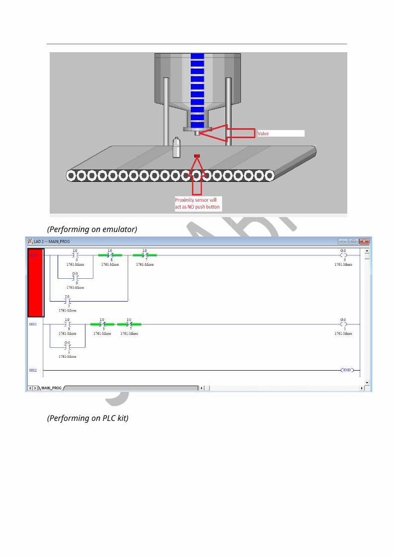
For reference diagram is shown below

(Performing on emulator)
(Performing on PLC kit)

Task 8 Reference Diagram:
Process:
There will be three sets of switches i.e. one set consist 2 buttons (ON/OFF).
When 1st button ON is pressed then motor of 1st conveyer belt is on and when OFF button is pressed then motor get off.
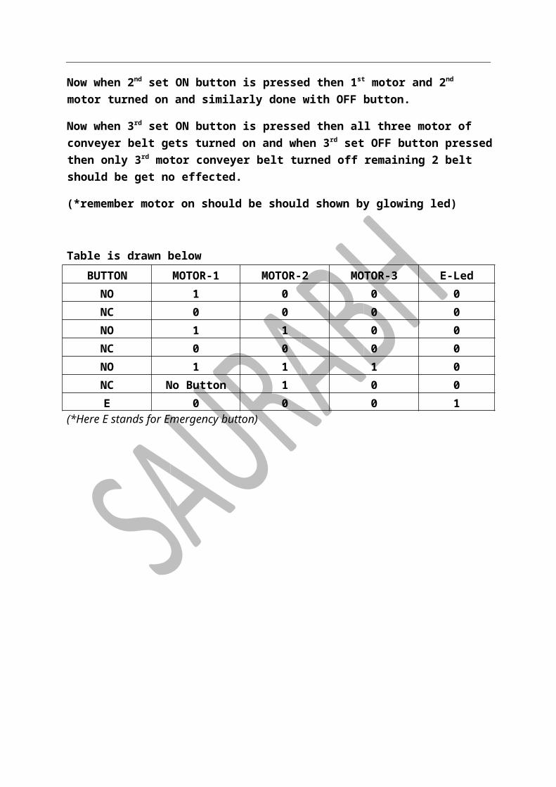
Now when 2nd set ON button is pressed then 1st motor and 2nd motor turned on and similarly done with OFF button.
Now when 3rd set ON button is pressed then all three motor of conveyer belt gets turned on and when 3rd set OFF button pressed then only 3rd motor conveyer belt turned off remaining 2 belt should be get no effected.
(*remember motor on should be should shown by glowing led)
Table is drawn below
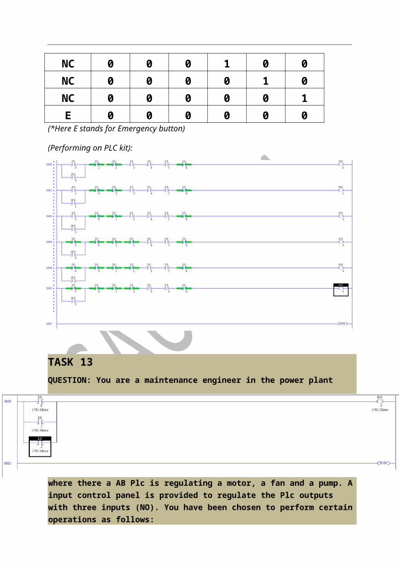
BUTTON MOTOR-1 MOTOR-2 MOTOR-3 E-Led NO 1 0 0 0 NC 0 0 0 0 NO 1 1 0 0 NC 0 0 0 0 NO 1 1 1 0 NC No Button 1 0 0 E 0 0 0 1
(*Here E stands for Emergency button)
(Performing on PLC kit)
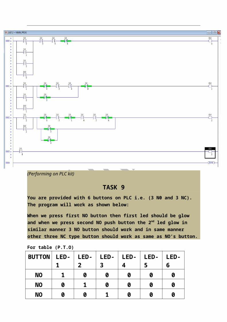
TASK 9 You are provided with 6 buttons on PLC i.e. (3 N0 and 3 NC). The program will work as shown below:
When we press first NO button then first led should be glow and when we press second NO push button the 2nd led glow in similar manner 3 NO button should work and in same manner other three NC type button should work as same as NO’s button.
For table (P.T.O)
BUTTON LED-1 LED-2 LED-3 LED-4 LED-5 LED-6 NO 1 0 0 0 0 0 NO 0 1 0 0 0 0 NO 0 0 1 0 0 0 NC 0 0 0 1 0 0 NC 0 0 0 0 1 0 NC 0 0 0 0 0 1 E 0 0 0 0 0 0
(*Here E stands for Emergency button)
(Performing on PLC kit):

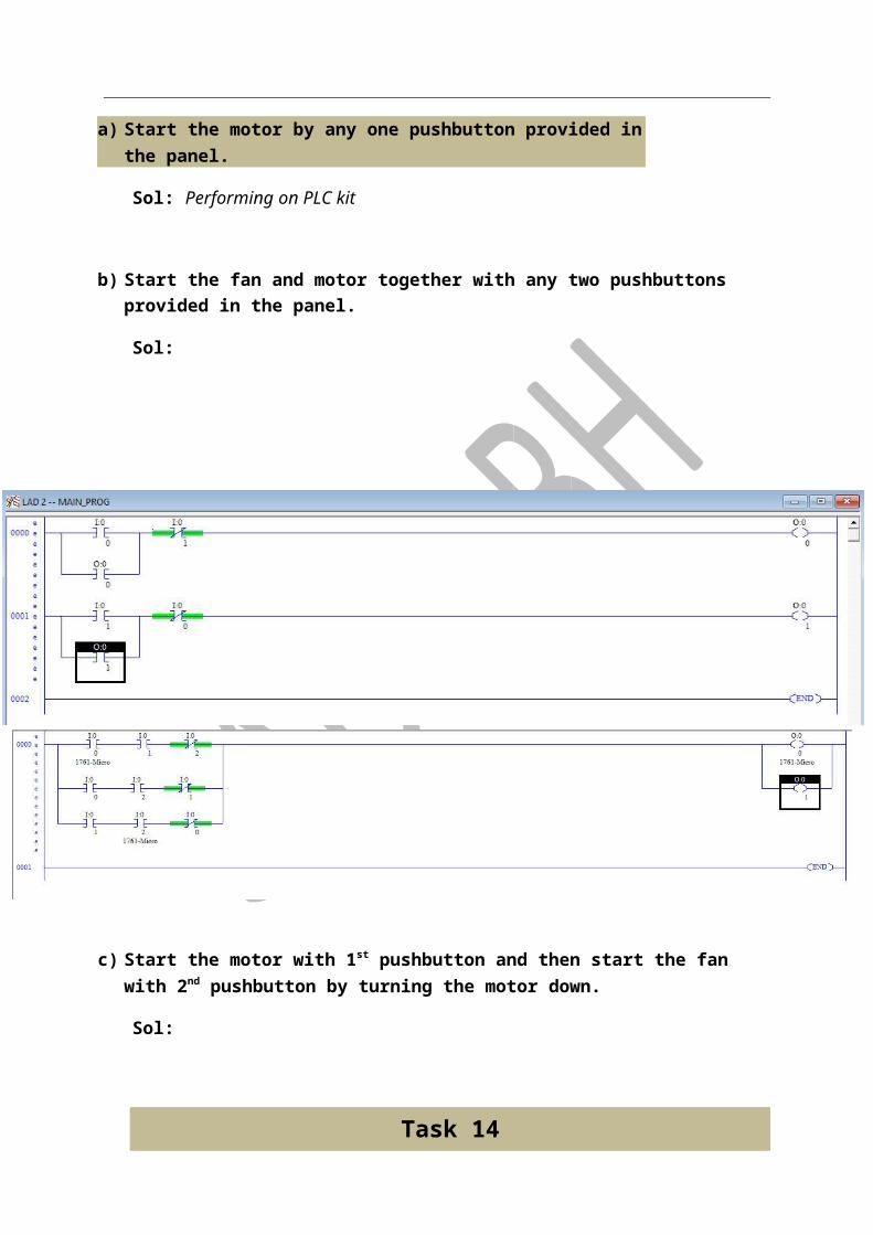
TASK 13 QUESTION: You are a maintenance engineer in the power plant where there a AB Plc is regulating a motor, a fan and a pump. A input control panel is provided to regulate the Plc outputs with three inputs (NO). You have been chosen to perform certain operations as follows:
a) Start the motor by any one pushbutton provided in the panel.
Sol: Performing on PLC kit
b) Start the fan and motor together with any two pushbuttons provided in the panel.
Sol:
c) Start the motor with 1st pushbutton and then start the fan with 2nd pushbutton by turning the motor down.
Sol:
Task 14

Question: Automation plant is manufacturing automobiles in regular basis and they need some logics to be developed so that manufacturing shouldn’t fall prey of any fault. The unit consists of the following outputs:-ENTRY, PROCESS and EXIT and with following inputs:- START,REGULATE and STOP. As a part of process team, you have been given duty to regulate the manufacturing unit. Your duties are as follows:
i) Start the plant with START button by switching the function of ENTRY and PROCESS. ii) REGULATE the unit by switching on the PROCESS iii) STOP the process by EXIT
Performing on PLC kit
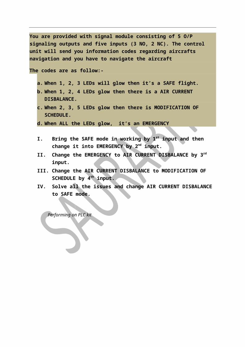
Task 15 Question: There are 5 lamps in a signaling unit of an aeronautical department which guide the aircrafts from ground. You are a signal officers working with the aeronautical department and you are responsible to navigate the aircraft in case of bad weather, aircraft malfunctions or later modification of schedule.
You are provided with signal module consisting of 5 O/P signaling outputs and five inputs (3 NO, 2 NC). The control unit will send you information codes regarding aircrafts navigation and you have to navigate the aircraft
The codes are as follow:-
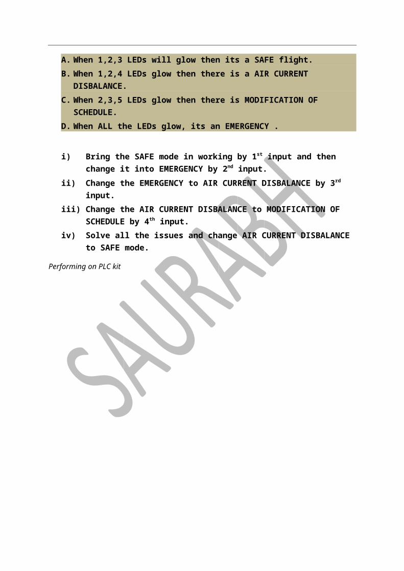
a. When 1, 2, 3 LEDs will glow then it’s a SAFE flight. b. When 1, 2, 4 LEDs glow then there is a AIR CURRENT DISBALANCE. c. When 2, 3, 5 LEDs glow then there is MODIFICATION OF SCHEDULE.
d. When ALL the LEDs glow, it’s an EMERGENCY
I. Bring the SAFE mode in working by 1st input and then change it into EMERGENCY by 2nd input.
II. Change the EMERGENCY to AIR CURRENT DISBALANCE by 3rd input. III. Change the AIR CURRENT DISBALANCE to MODIFICATION OF SCHEDULE by 4th
input. IV. Solve all the issues and change AIR CURRENT DISBALANCE to SAFE mode.
Performing on PLC kit

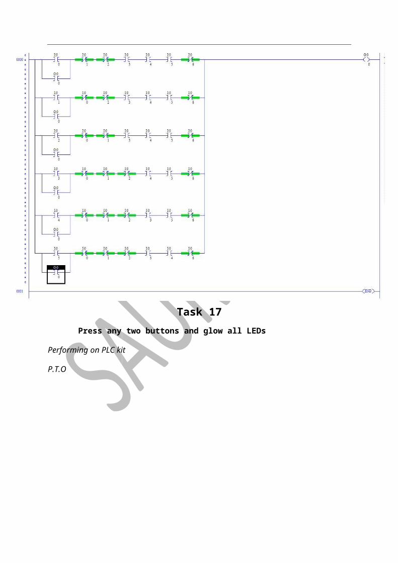
Task 16 Press any one of the six pushbuttons provided and glow the 1st LED.
Performing on PLC kit
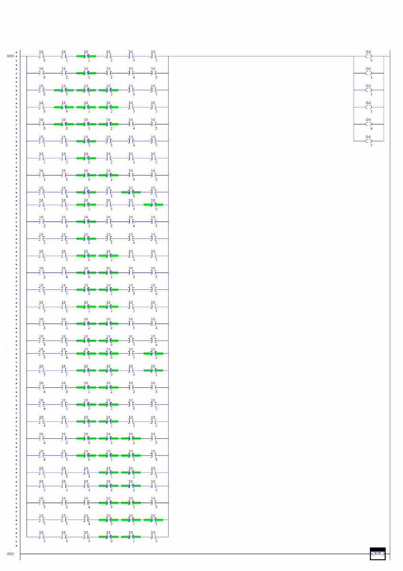
Task 17 Press any two buttons and glow all LEDs
Performing on PLC kit
P.T.O

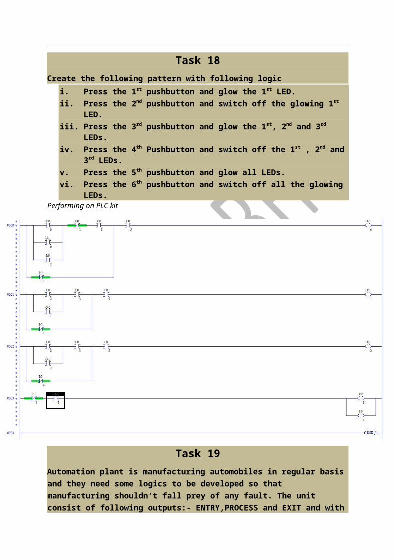
Task 18 Create the following pattern with following logic
i. Press the 1st pushbutton and glow the 1st LED. ii. Press the 2nd pushbutton and switch off the glowing 1st LED. iii. Press the 3rd pushbutton and glow the 1st, 2nd and 3rd LEDs. iv. Press the 4th Pushbutton and switch off the 1st , 2nd and 3rd LEDs. v. Press the 5th pushbutton and glow all LEDs. vi. Press the 6th pushbutton and switch off all the glowing LEDs.
Performing on PLC kit
Task 19 Automation plant is manufacturing automobiles in regular basis and they need some logics to be developed so that manufacturing shouldn’t fall prey of any fault. The unit consist of following outputs:- ENTRY,PROCESS and EXIT and with following inputs:- START, REGULATE and STOP. As a part of process team, you have been given duty to regulate the manufacturing unit. Your duties are as follows.
i. Start the plant with START button by switching the function to ENTRY and PROCESS.
ii. REGULATE the unit by switching on the process. iii. STOP the process by EXIT.
Performing on PLC kit
Task 20 There are 5 lamps in a SIGNALLING unit of an aeronautical department which guide the aircraft from ground. You are a signal officer working with the aeronautical department and you are responsible to navigate the aircrafts in case of the bad weather, aircraft malfunctions and later modification of schedule.
You are provided with signal module consisting of 5 O/P signalling outputs and five inputs (3 NO, 2 NC). The control unit will send you information codes regarding aircraft navigation and you have to navigate the aircraft.
The code is as follows:
A. When 1,2,3 LEDs will glow then its a SAFE flight. B. When 1,2,4 LEDs glow then there is a AIR CURRENT DISBALANCE. C. When 2,3,5 LEDs glow then there is MODIFICATION OF SCHEDULE. D. When ALL the LEDs glow, its an EMERGENCY .
i) Bring the SAFE mode in working by 1st input and then change it into EMERGENCY
by 2nd input. ii) Change the EMERGENCY to AIR CURRENT DISBALANCE by 3rd input. iii) Change the AIR CURRENT DISBALANCE to MODIFICATION OF SCHEDULE by 4th
input. iv) Solve all the issues and change AIR CURRENT DISBALANCE to SAFE mode.
Performing on PLC kit

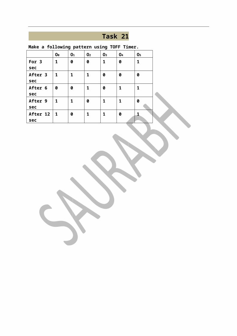
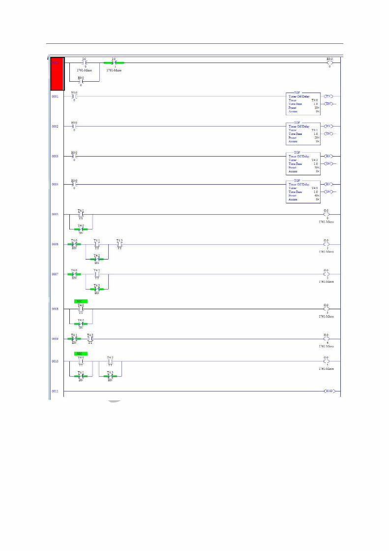
Task 21
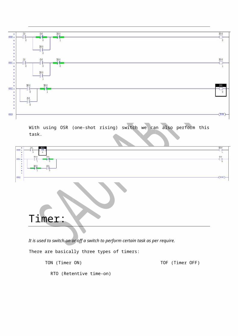
With using an NO button to perform on and off task with same button and use also same LED.
Performing on PLC kit
With using OSR (one-shot rising) switch we can also perform this task.
Timer:
It is used to switch on or off a switch to perform certain task as per require.
There are basically three types of timers:
TON (Timer ON) TOF (Timer OFF)
RTO (Retentive time-on)
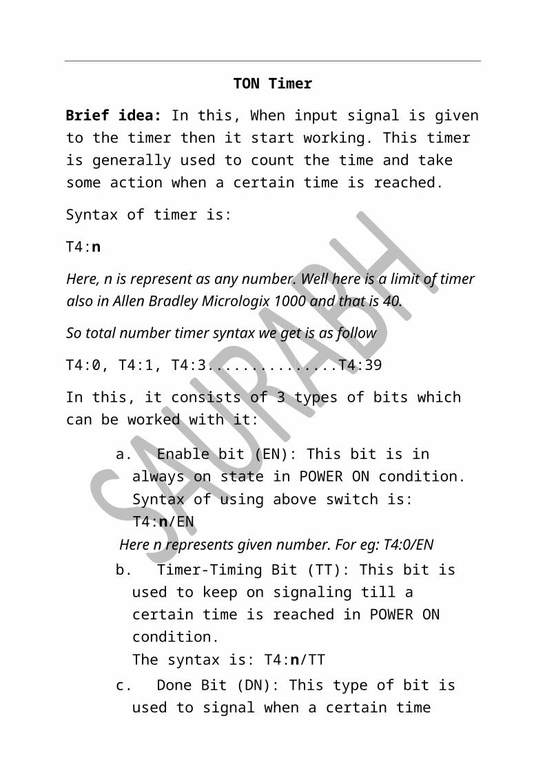
TON Timer
Brief idea: In this, When input signal is given to the timer then it start working. This timer is generally used to count the time and take some action when a certain time is reached.
Syntax of timer is:
T4:n
Here, n is represent as any number. Well here is a limit of timer also in Allen Bradley Micrologix 1000 and that is 40.
So total number timer syntax we get is as follow
T4:0, T4:1, T4:3...............T4:39
In this, it consists of 3 types of bits which can be worked with it:
a. Enable bit (EN): This bit is in always on state in POWER ON condition. Syntax of using above switch is: T4:n/EN Here n represents given number. For eg: T4:0/EN
b. Timer-Timing Bit (TT): This bit is used to keep on signaling till a certain time is reached in POWER ON condition. The syntax is: T4:n/TT
c. Done Bit (DN): This type of bit is used to signal when a certain time period is reached in POWER ON condition. It is generally used to notify when a set time period is reached. The syntax of DN bit is: T4:n/DN
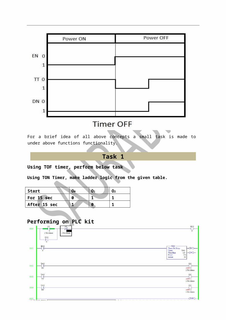
For a brief idea of all above concepts a small task is made to under above functions functionality.
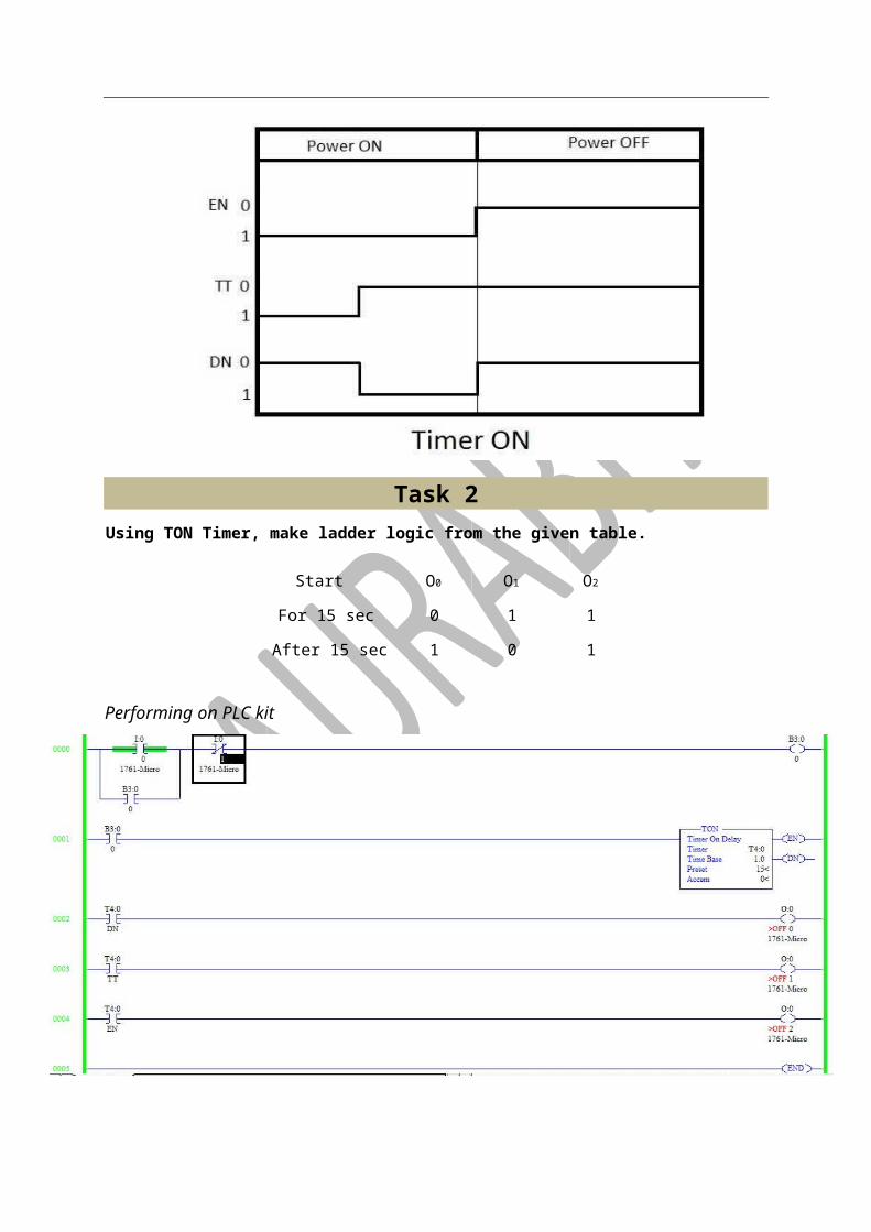
Task 1 Observing characteristics of TON type timer
Graph of TON timer
Task 2 Using TON Timer, make ladder logic from the given table.
Start O0 O1 O2
For 15 sec 0 1 1
After 15 sec 1 0 1
Performing on PLC kit

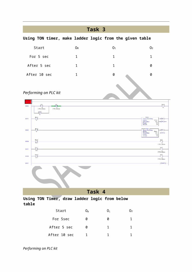
Task 3 Using TON timer, make ladder logic from the given table
Start O0 O1 O2
For 5 sec 1 1 1
After 5 sec 1 1 0
After 10 sec 1 0 0
Performing on PLC kit
Task 4 Using TON Timer, draw ladder logic from below table
Start O0 O1 O2
For 5sec 0 0 1
After 5 sec 0 1 1
After 10 sec 1 1 1
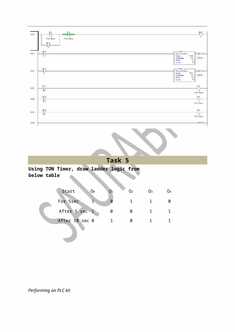
Performing on PLC kit
Task 5 Using TON Timer, draw ladder logic from below table
Start O0 O1 O2 O3 O4
For 5sec 1 0 1 1 0
After 5 sec 1 0 0 1 1
After 10 sec 0 1 0 1 1
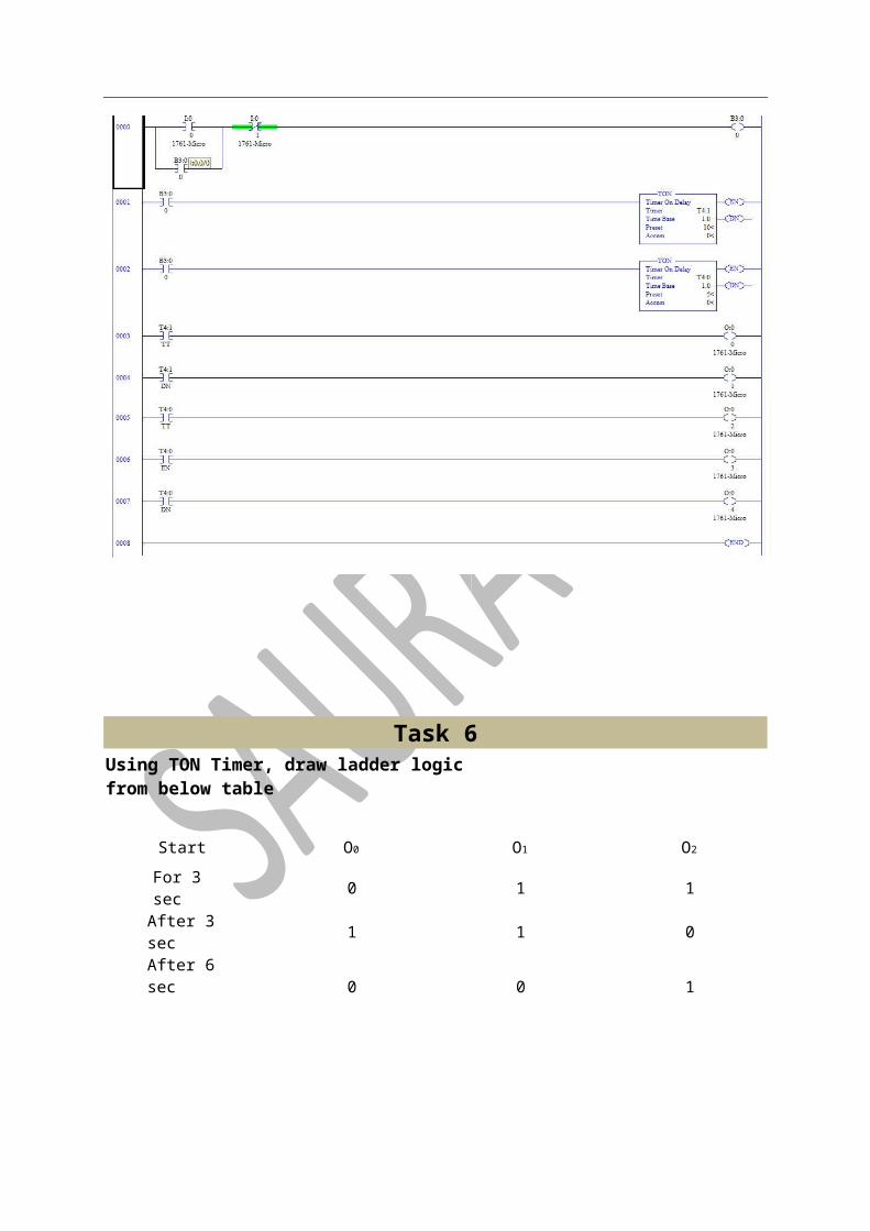
Performing on PLC kit
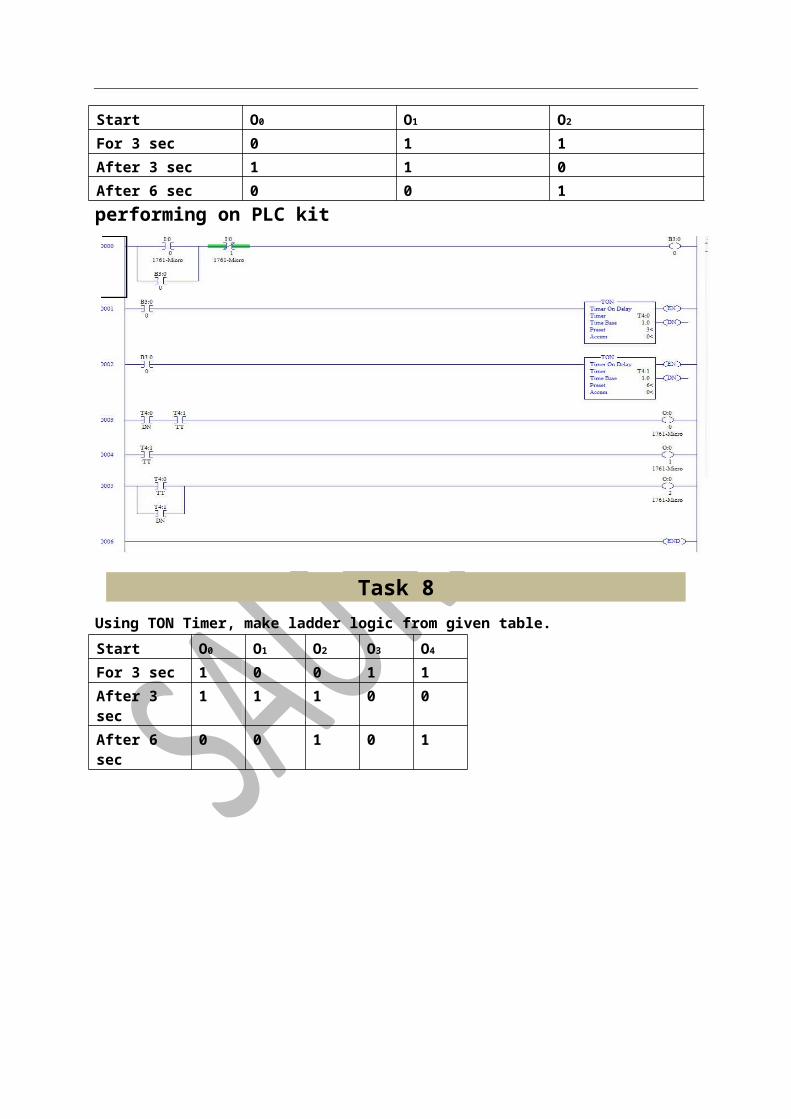
Task 6 Using TON Timer, draw ladder logic from below table
Start O0 O1 O2
For 3 sec 0 1 1

After 3 sec 1 1 0
After 6 sec 0 0 1
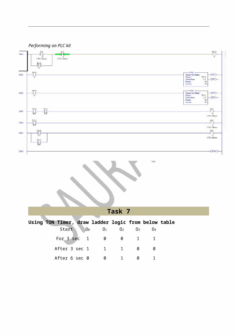
Performing on PLC kit
Task 7 Using TON Timer, draw ladder logic from below table
Start O0 O1 O2 O3 O4
For 3 sec 1 0 0 1 1
After 3 sec 1 1 1 0 0
After 6 sec 0 0 1 0 1
Performing on PLC kit
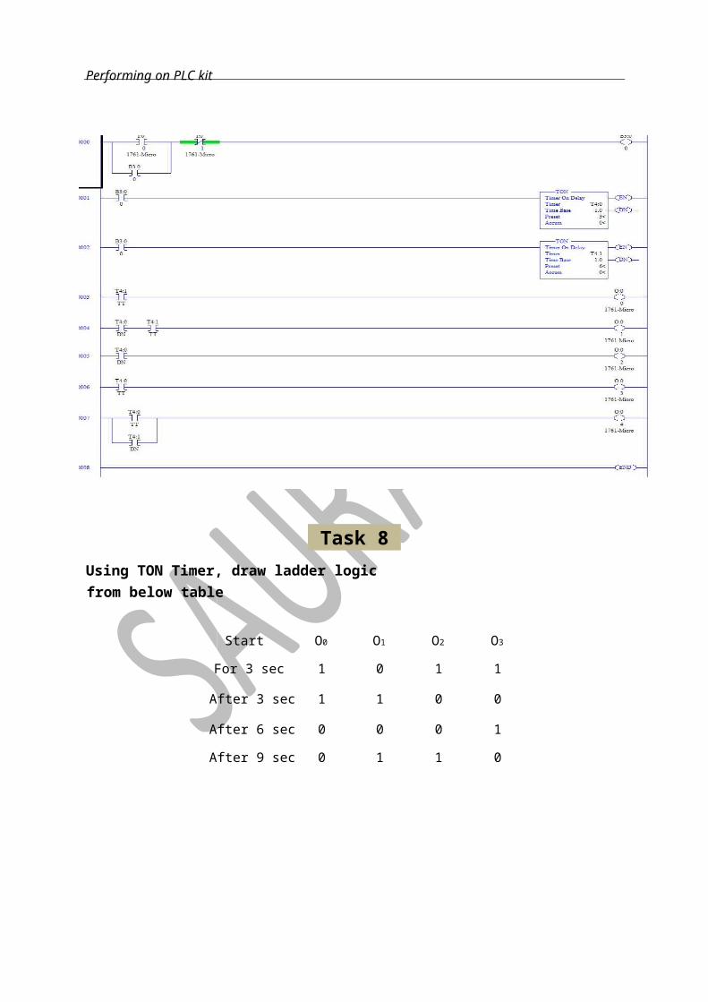
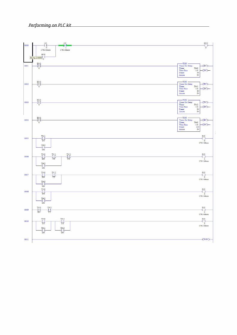
Task 8 Using TON Timer, draw ladder logic from below table
Start O0 O1 O2 O3
For 3 sec 1 0 1 1
After 3 sec 1 1 0 0
After 6 sec 0 0 0 1
After 9 sec 0 1 1 0
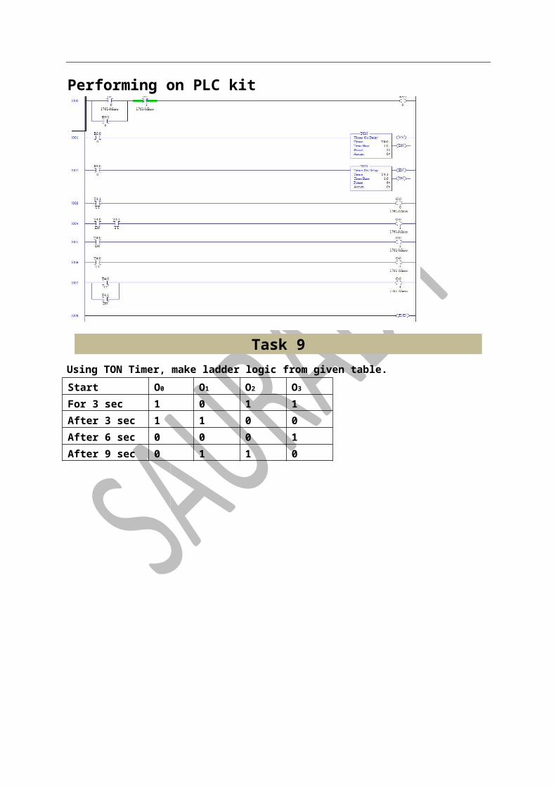
Performing on PLC kit
Task 9 Using TON Timer, draw ladder logic from below table
Start O0 O1 O2 O3 O4 O5
For 3 sec 1 0 0 1 0 1
After 3 sec 1 1 1 0 0 0
After 6 sec 0 0 1 0 1 1
After 9 sec 1 1 0 1 1 0
After 1 0 1 1 0 1
Performing on PLC kit
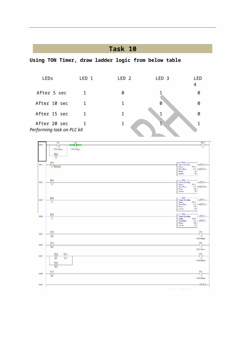
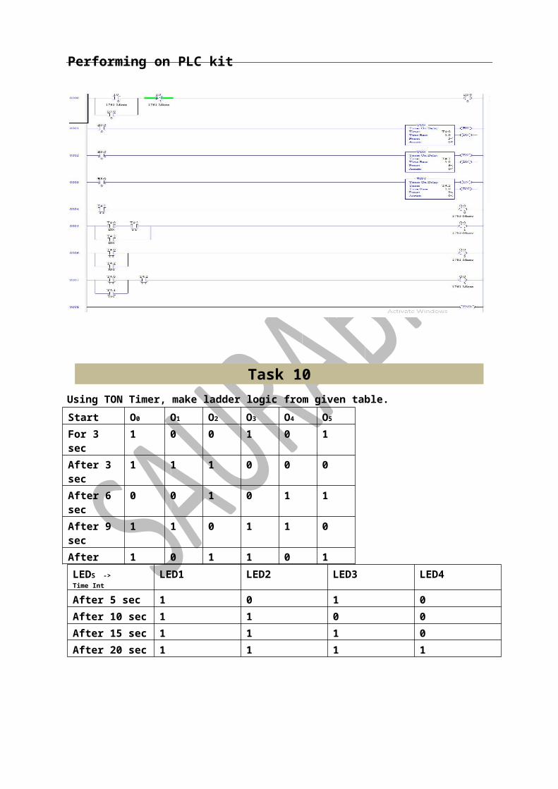
Task 10 Using TON Timer, draw ladder logic from below table
LEDs LED 1 LED 2 LED 3 LED 4
After 5 sec 1 0 1 0
After 10 sec 1 1 0 0
After 15 sec 1 1 1 0
After 20 sec 1 1 1 1 Performing task on PLC kit
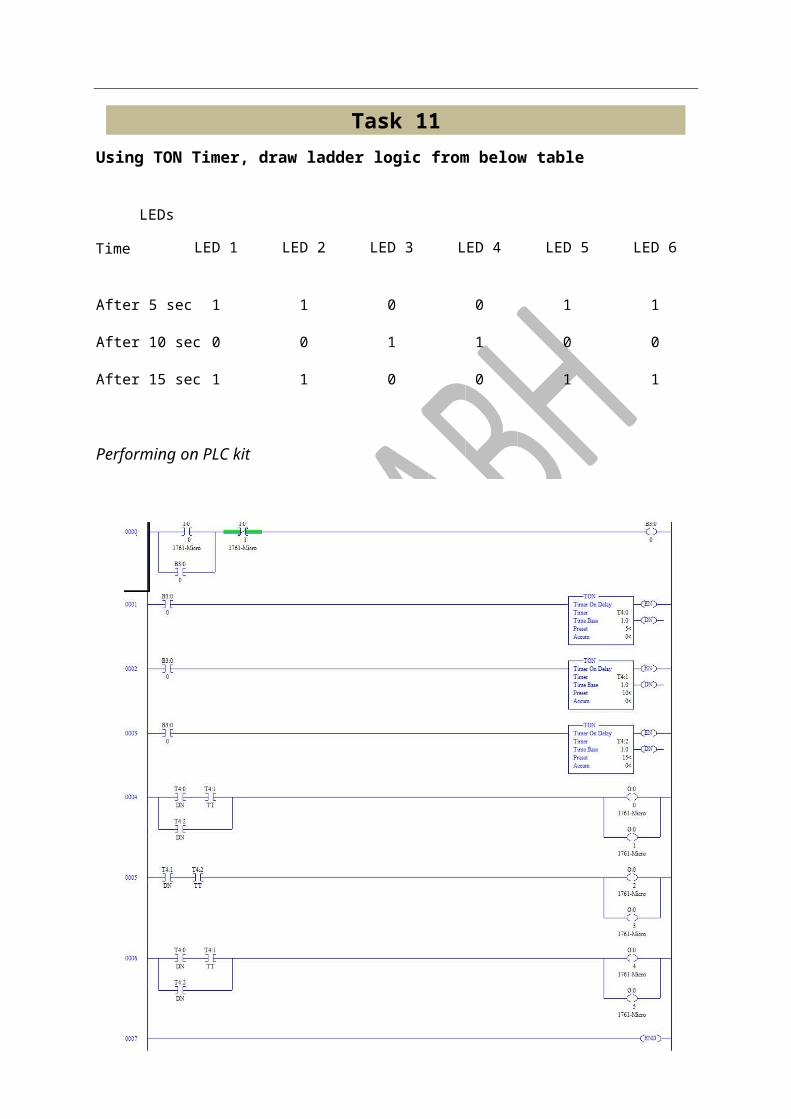
Task 11 Using TON Timer, draw ladder logic from below table

LED 1 LED 2 LED 3 LED 4 LED 5 LED 6
After 5 sec 1 1 0 0 1 1
After 10 sec 0 0 1 1 0 0
After 15 sec 1 1 0 0 1 1
Performing on PLC kit
Task 12 Using TON Timer, make TOFF Timer.
Performing on PLC kit
Time
LEDs
TOF Timer
Brief idea: In this, when timer is come in off state then it starts working. This timer is generally used to take action when after a certain period of time.
Syntax of timer is:
T4:n
Here, n is represent as any number. Well here is a limit of timer also in Allen Bradley Micrologix 1000 and that is 40.
So total number timer syntax we get is as follow
T4:0, T4:1, T4:3...............T4:39
In this, it consists of 3 types of bits which can be worked with it:
a. Enable bit (EN): This bit is in always on state in POWER ON condition. It work same as in TON timer. Syntax of using above switch is: T4:n/EN Here n represents given number. For eg: T4:0/EN
b. Timer-Timing Bit (TT): This bit is used to keep signalling till a certain time is reached in POWER OFF condition.
The syntax is: T4:n/TT c. Done Bit (DN): It is also keep on signalling till a certain time period is reached but it
also keep on signalling in Power ON condition which make it different from timer timing bit (TT Bit). It is generally used to notify when a set time period is reached. The syntax of DN bit is: T4:n/DN
Graph of TOFF Timer is shown below for better understanding:
For a brief idea of all above concepts a small task is made to under above functions functionality.
Task 1 Using TOF timer, perform below task
Using TON Timer, make ladder logic from the given table. Start O0 O1 O2
For 15 sec 0 1 1 After 15 sec 1 0 1
Performing on PLC kit
Task 4 Using TON Timer, make ladder logic from the given table.
Start O0 O1 O2
For 5 sec 1 1 1 After 5 sec 1 1 0 After 10 sec 1 0 0
Performing on PLC kit
Task 5 Using TON Timer, make ladder logic from the given table. Start O0 O1 O2
For 5sec 0 0 1 After 5 sec 0 1 1 After 10 sec 1 1 1
Performing on PLC kit
Task 6 Using TON Timer, make ladder logic from the given table. Start O0 O1 O2 O3 O4
For 5sec 1 0 1 1 0 After 5 sec 1 0 0 1 1 After 10 sec 0 1 0 1 1
Task 7
Using TON Timer, make ladder logic from given table. Start O0 O1 O2
For 3 sec 0 1 1 After 3 sec 1 1 0
Performing on plc kitPerforming on plc kitPerforming on plc kitPerforming on plc kitPerforming on plc kitPerforming on plc kitPerforming on plc kitPerforming on plc kitPerforming on plc kitPerforming on plc kitPerforming on plc kitPerforming on plc kitPerforming on plc kitPerforming on plc kitPerforming on plc kitPerforming on plc kitPerforming on plc kitPerforming on plc kitPerforming on plc kitPerforming on plc kitPerforming on plc kitPerforming on plc kitPerforming on plc kitPerforming on plc kitPerforming on plc kitPerforming on plc kitPerforming on plc kitPerforming on plc kitPerforming on plc kitPerforming on plc kitPerforming on plc kitPerforming on plc kitPerforming on plc kitPerforming on plc kitPerforming on plc kitPerforming on plc kitPerforming on plc kitPerforming on plc kitPerforming on plc kitPerforming on plc kitPerforming on plc kitPerforming on plc kitPerforming on plc kitPerforming on plc kitPerforming on plc kitPerforming on plc kitPerforming on plc kitPerforming on plc kitPerforming on plc kitPerforming on plc kitPerforming on plc kitPerforming on plc kitPerforming on plc kitPerforming on plc kitPerforming on plc kitPerforming on plc kitPerforming on plc kitPerforming on plc kitPerforming on plc kitPerforming on plc kitPerforming on plc kitPerforming on plc kitPerforming on plc kitPerforming on plc kitPerforming on plc kitPerforming on plc kitPerforming on plc kitPerforming on plc kitPerforming on plc kitPerforming on plc kitPerforming on plc kitPerforming on plc kitPerforming on plc kitPerforming on plc kitPerforming on plc kitPerforming on plc kitPerforming on plc kitPerforming on plc kitPerforming on plc kitPerforming on plc kitPerforming on plc kitPerforming on plc kitPerforming on plc kitPerforming on plc kitPerforming on plc kitPerforming on plc kitPerforming on plc kitPerforming on plc kitPerforming on plc kitPerforming on plc kitPerforming on plc kitPerforming on plc kitPerforming on plc kitPerforming on plc kitPerforming on plc kitPerforming on plc kitPerforming on plc kitPerforming on plc kitPerforming on plc kitPerforming on plc kitPerforming on plc kitPerforming on plc kitPerforming on plc kitPerforming on plc kitPerforming on plc kitPerforming on plc kitPerforming on plc kitPerforming on plc kitPerforming on plc kitPerforming on plc kitPerforming on plc kitPerforming on plc kitPerforming on plc kitPerforming on plc kitPerforming on plc kitPerforming on plc kitPerforming on plc kitPerforming on plc kitPerforming on plc kitPerforming on plc kitPerforming on plc kitPerforming on plc kitPerforming on plc kitPerforming on plc kitPerforming on plc kitPerforming on plc kitPerforming on plc kitPerforming on plc kitPerforming on plc kitPerforming on plc kitPerforming on plc kitPerforming on plc kitPerforming on plc kitPerforming on plc kitPerforming on plc kitPerforming on plc kitPerforming on plc kitPerforming on plc kitPerforming on plc kitPerforming on plc kitPerforming on plc kitPerforming on plc kitPerforming on plc kitPerforming on plc kitPerforming on plc kitPerforming on plc kitPerforming on plc kitPerforming on plc kitPerforming on plc kitPerforming on plc kitPerforming on plc kitPerforming on plc kitPerforming on plc kitPerforming on plc kitPerforming on plc kitPerforming on plc kitPerforming on plc kitPerforming on plc kitPerforming on plc kitPerforming on plc kitPerforming on plc kitPerforming on plc kitPerforming on plc kitPerforming on plc kitPerforming on plc kitPerforming on plc kitPerforming on plc kitPerforming on plc kitPerforming on plc kitPerforming on plc kitPerforming on plc kitPerforming on plc kitPerforming on plc kitPerforming on plc kitPerforming on plc kitPerforming on plc kitPerforming on plc kitPerforming on plc kitPerforming on plc kitPerforming on plc kitPerforming on plc kitPerforming on plc kitPerforming on plc kitPerforming on plc kitPerforming on plc kitPerforming on plc kitPerforming on plc kitPerforming on plc kitPerforming on plc kitPerforming on plc kitPerforming on plc kitPerforming on plc kitPerforming on plc kit
After 6 sec 0 0 1 performing on PLC kit
Task 8 Using TON Timer, make ladder logic from given table. Start O0 O1 O2 O3 O4
For 3 sec 1 0 0 1 1 After 3 sec 1 1 1 0 0 After 6 sec 0 0 1 0 1
Performing on PLC kit
Task 9 Using TON Timer, make ladder logic from given table.

Start O0 O1 O2 O3
For 3 sec 1 0 1 1 After 3 sec 1 1 0 0 After 6 sec 0 0 0 1 After 9 sec 0 1 1 0
Performing on PLC kit
Task 10 Using TON Timer, make ladder logic from given table. Start O0 O1 O2 O3 O4 O5
For 3 sec 1 0 0 1 0 1 After 3 sec 1 1 1 0 0 0 After 6 sec 0 0 1 0 1 1 After 9 sec 1 1 0 1 1 0 After 1 0 1 1 0 1
LEDS -> Time Int
LED1 LED2 LED3 LED4
After 5 sec 1 0 1 0 After 10 sec 1 1 0 0 After 15 sec 1 1 1 0 After 20 sec 1 1 1 1

Performing on PLC kit
Task 11
Make a following pattern using TON Timer.
Performing on PLC kit
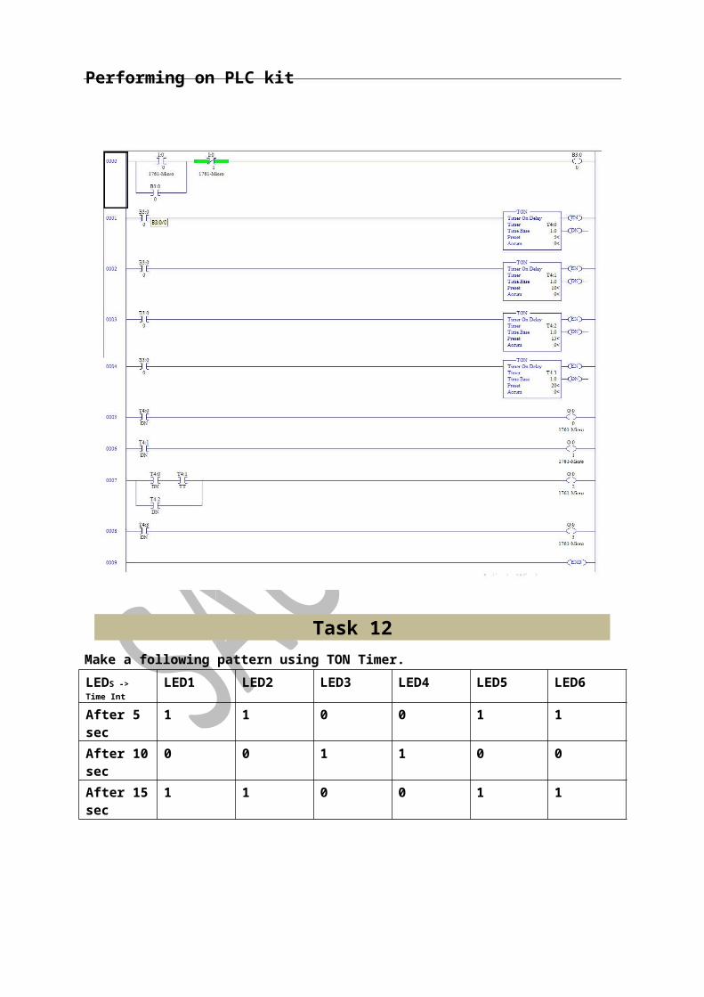
Task 12 Make a following pattern using TON Timer. LEDS -> Time Int
LED1 LED2 LED3 LED4 LED5 LED6
After 5 sec 1 1 0 0 1 1 After 10 sec 0 0 1 1 0 0 After 15 sec 1 1 0 0 1 1
Performing on PLC kit
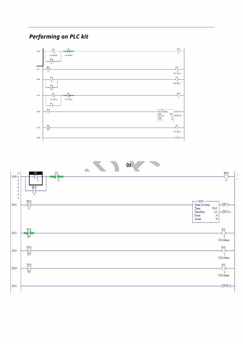
Task 13 Make TON Timer working as TOFF Timer.

Performing on PLC kit
Or
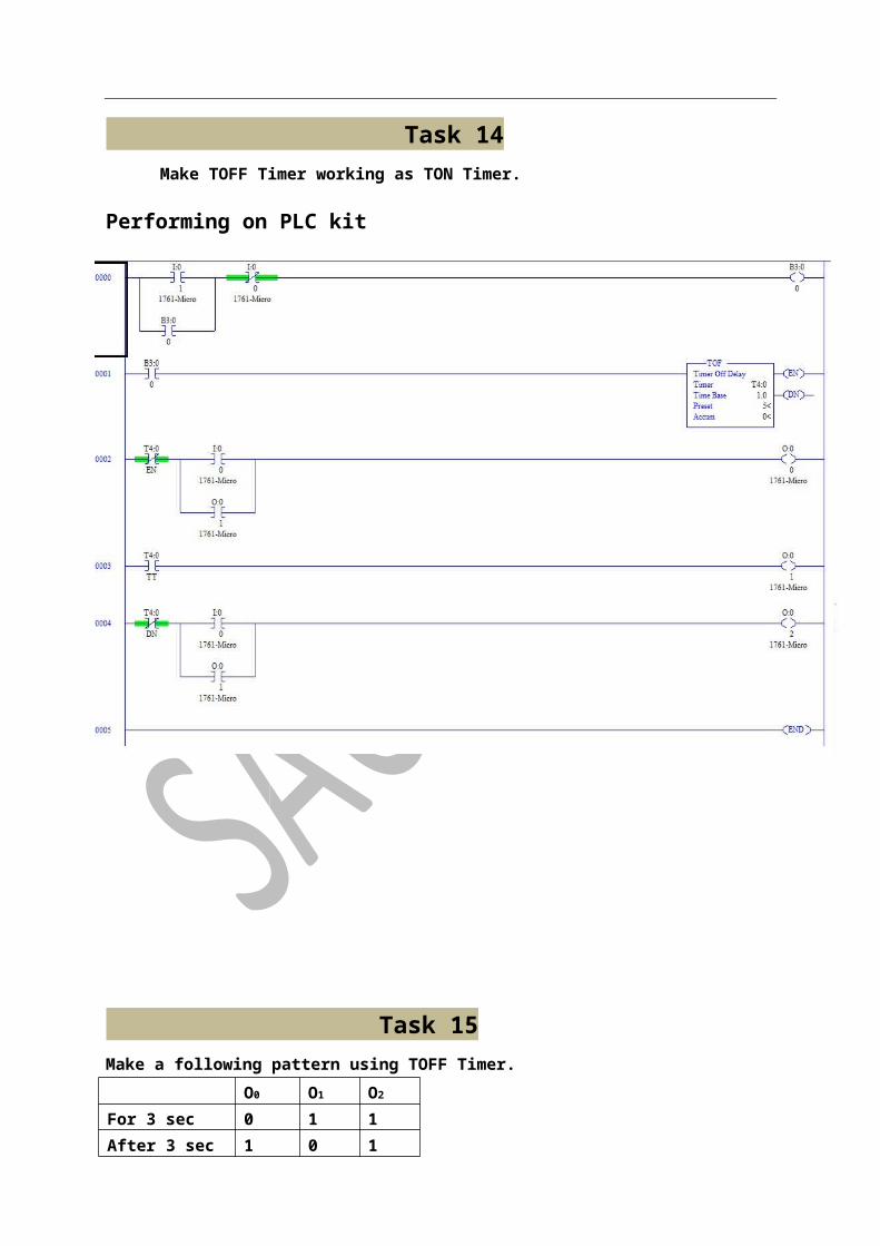
Task 14 Make TOFF Timer working as TON Timer.
Performing on PLC kit
Task 15 Make a following pattern using TOFF Timer. O0 O1 O2
For 3 sec 0 1 1 After 3 sec 1 0 1
Performing on PLC kit
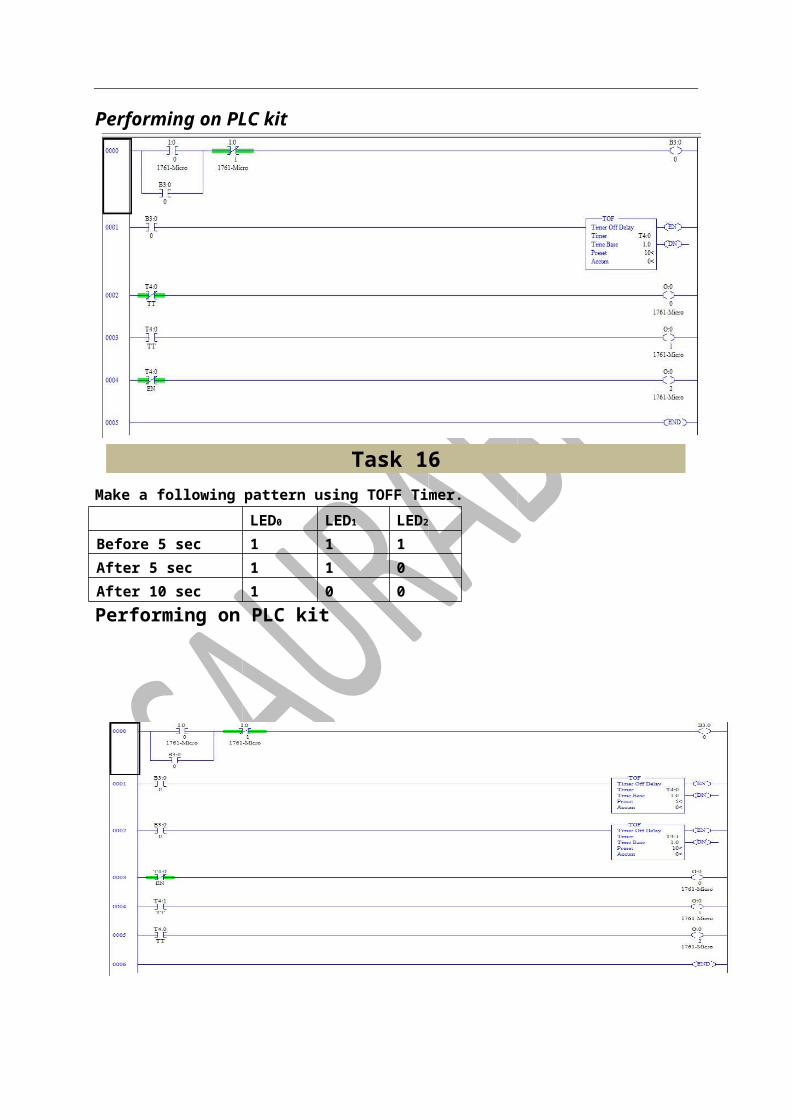
Task 16 Make a following pattern using TOFF Timer. LED0 LED1 LED2
Before 5 sec 1 1 1 After 5 sec 1 1 0 After 10 sec 1 0 0 Performing on PLC kit
Task 21 Make a following pattern using TOFF Timer. O0 O1 O2 O3 O4 O5
For 3 sec 1 0 0 1 0 1 After 3 sec 1 1 1 0 0 0 After 6 sec 0 0 1 0 1 1 After 9 sec 1 1 0 1 1 0 After 12 sec 1 0 1 1 0 1
Performing on PLC kitPerforming on PLC kitPerforming on PLC kitPerforming on PLC kitPerforming on PLC kitPerforming on PLC kitPerforming on PLC kitPerforming on PLC kitPerforming on PLC kitPerforming on PLC kitPerforming on PLC kitPerforming on PLC kitPerforming on PLC kitPerforming on PLC kitPerforming on PLC kitPerforming on PLC kitPerforming on PLC kitPerforming on PLC kitPerforming on PLC kitPerforming on PLC kitPerforming on PLC kitPerforming on PLC kitPerforming on PLC kitPerforming on PLC kitPerforming on PLC kitPerforming on PLC kitPerforming on PLC kitPerforming on PLC kitPerforming on PLC kitPerforming on PLC kitPerforming on PLC kitPerforming on PLC kitPerforming on PLC kitPerforming on PLC kitPerforming on PLC kitPerforming on PLC kitPerforming on PLC kitPerforming on PLC kitPerforming on PLC kitPerforming on PLC kitPerforming on PLC kitPerforming on PLC kitPerforming on PLC kitPerforming on PLC kitPerforming on PLC kitPerforming on PLC kitPerforming on PLC kitPerforming on PLC kitPerforming on PLC kitPerforming on PLC kitPerforming on PLC kitPerforming on PLC kitPerforming on PLC kitPerforming on PLC kitPerforming on PLC kitPerforming on PLC kitPerforming on PLC kitPerforming on PLC kitPerforming on PLC kitPerforming on PLC kitPerforming on PLC kitPerforming on PLC kitPerforming on PLC kitPerforming on PLC kitPerforming on PLC kitPerforming on PLC kitPerforming on PLC kitPerforming on PLC kitPerforming on PLC kitPerforming on PLC kitPerforming on PLC kitPerforming on PLC kitPerforming on PLC kitPerforming on PLC kitPerforming on PLC kitPerforming on PLC kitPerforming on PLC kitPerforming on PLC kitPerforming on PLC kitPerforming on PLC kitPerforming on PLC kitPerforming on PLC kitPerforming on PLC kitPerforming on PLC kitPerforming on PLC kitPerforming on PLC kitPerforming on PLC kitPerforming on PLC kitPerforming on PLC kitPerforming on PLC kitPerforming on PLC kitPerforming on PLC kitPerforming on PLC kitPerforming on PLC kitPerforming on PLC kitPerforming on PLC kitPerforming on PLC kitPerforming on PLC kitPerforming on PLC kitPerforming on PLC kitPerforming on PLC kitPerforming on PLC kitPerforming on PLC kitPerforming on PLC kitPerforming on PLC kitPerforming on PLC kitPerforming on PLC kitPerforming on PLC kitPerforming on PLC kitPerforming on PLC kitPerforming on PLC kitPerforming on PLC kitPerforming on PLC kitPerforming on PLC kitPerforming on PLC kitPerforming on PLC kitPerforming on PLC kitPerforming on PLC kitPerforming on PLC kitPerforming on PLC kitPerforming on PLC kitPerforming on PLC kitPerforming on PLC kitPerforming on PLC kitPerforming on PLC kitPerforming on PLC kitPerforming on PLC kitPerforming on PLC kitPerforming on PLC kitPerforming on PLC kitPerforming on PLC kitPerforming on PLC kitPerforming on PLC kitPerforming on PLC kitPerforming on PLC kitPerforming on PLC kitPerforming on PLC kitPerforming on PLC kitPerforming on PLC kitPerforming on PLC kitPerforming on PLC kitPerforming on PLC kitPerforming on PLC kitPerforming on PLC kitPerforming on PLC kitPerforming on PLC kitPerforming on PLC kitPerforming on PLC kitPerforming on PLC kitPerforming on PLC kitPerforming on PLC kitPerforming on PLC kitPerforming on PLC kitPerforming on PLC kitPerforming on PLC kitPerforming on PLC kitPerforming on PLC kitPerforming on PLC kitPerforming on PLC kitPerforming on PLC kitPerforming on PLC kitPerforming on PLC kitPerforming on PLC kitPerforming on PLC kitPerforming on PLC kitPerforming on PLC kitPerforming on PLC kitPerforming on PLC kitPerforming on PLC kitPerforming on PLC kitPerforming on PLC kitPerforming on PLC kitPerforming on PLC kitPerforming on PLC kitPerforming on PLC kitPerforming on PLC kitPerforming on PLC kitPerforming on PLC kitPerforming on PLC kitPerforming on PLC kitPerforming on PLC kitPerforming on PLC kitPerforming on PLC kitPerforming on PLC kitPerforming on PLC kitPerforming on PLC kitPerforming on PLC kitPerforming on PLC kitPerforming on PLC kitPerforming on PLC kitPerforming on PLC kitPerforming on PLC kitPerforming on PLC kit
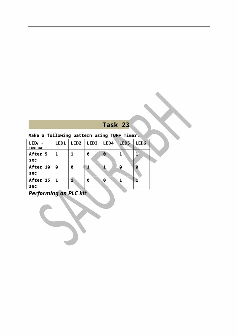
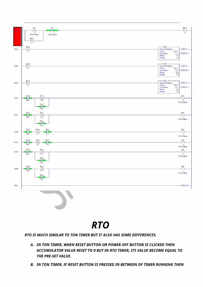
Task 23 Make a following pattern using TOFF Timer. LEDS -> Time Int
LED1 LED2 LED3 LED4 LED5 LED6
After 5 sec 1 1 0 0 1 1 After 10 sec 0 0 1 1 0 0 After 15 sec 1 1 0 0 1 1 Performing on PLC kit
RTO RTO IS MUCH SIMILAR TO TON TIMER BUT IT ALSO HAS SOME DIFFERENCES.
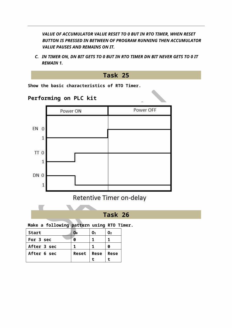
A. IN TON TIMER, WHEN RESET BUTTON OR POWER OFF BUTTON IS CLICKED THEN ACCUMULATOR VALUE RESET TO 0 BUT IN RTO TIMER, ITS VALUE BECOME EQUAL TO THE PRE-SET VALUE.
B. IN TON TIMER, IF RESET BUTTON IS PRESSED IN BETWEEN OF TIMER RUNNING THEN VALUE OF ACCUMULATOR VALUE RESET TO 0 BUT IN RTO TIMER, WHEN RESET BUTTON IS PRESSED IN BETWEEN OF PROGRAM RUNNING THEN ACCUMULATOR VALUE PAUSES AND REMAINS ON IT.
C. IN TIMER ON, DN BIT GETS TO 0 BUT IN RTO TIMER DN BIT NEVER GETS TO 0 IT REMAIN 1.
Task 25 Show the basic characteristics of RTO Timer.
Performing on PLC kit
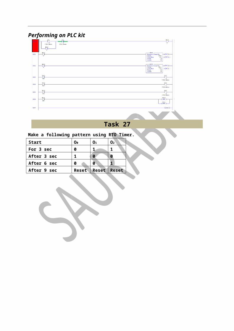
Task 26 Make a following pattern using RTO Timer. Start O0 O1 O2
For 3 sec 0 1 1 After 3 sec 1 1 0 After 6 sec Reset Reset Reset Performing on PLC kit

Task 27 Make a following pattern using RTO Timer. Start O0 O1 O2
For 3 sec 0 1 1 After 3 sec 1 0 0 After 6 sec 0 0 1 After 9 sec Reset Reset Reset
Task 28 Make a following pattern using RTO Timer. Start O0 O1 O2 O3 O4 O5
After 2 sec 0 1 1 1 0 1 After 4 sec 1 0 0 1 1 1 After 6 sec 0 0 1 0 1 0 After 8 sec 1 1 0 1 0 0 After 10 sec Reset Reset Reset Reset Reset Reset
Performing on PLC kitPerforming on PLC kitPerforming on PLC kitPerforming on PLC kitPerforming on PLC kitPerforming on PLC kitPerforming on PLC kitPerforming on PLC kitPerforming on PLC kitPerforming on PLC kitPerforming on PLC kitPerforming on PLC kitPerforming on PLC kitPerforming on PLC kitPerforming on PLC kitPerforming on PLC kitPerforming on PLC kitPerforming on PLC kitPerforming on PLC kitPerforming on PLC kitPerforming on PLC kitPerforming on PLC kitPerforming on PLC kitPerforming on PLC kitPerforming on PLC kitPerforming on PLC kitPerforming on PLC kitPerforming on PLC kitPerforming on PLC kitPerforming on PLC kitPerforming on PLC kitPerforming on PLC kitPerforming on PLC kitPerforming on PLC kitPerforming on PLC kitPerforming on PLC kitPerforming on PLC kitPerforming on PLC kitPerforming on PLC kitPerforming on PLC kitPerforming on PLC kitPerforming on PLC kitPerforming on PLC kitPerforming on PLC kitPerforming on PLC kitPerforming on PLC kitPerforming on PLC kitPerforming on PLC kitPerforming on PLC kitPerforming on PLC kitPerforming on PLC kitPerforming on PLC kitPerforming on PLC kitPerforming on PLC kitPerforming on PLC kitPerforming on PLC kitPerforming on PLC kitPerforming on PLC kitPerforming on PLC kitPerforming on PLC kitPerforming on PLC kitPerforming on PLC kitPerforming on PLC kitPerforming on PLC kitPerforming on PLC kitPerforming on PLC kitPerforming on PLC kitPerforming on PLC kitPerforming on PLC kitPerforming on PLC kitPerforming on PLC kitPerforming on PLC kitPerforming on PLC kitPerforming on PLC kitPerforming on PLC kitPerforming on PLC kitPerforming on PLC kitPerforming on PLC kitPerforming on PLC kitPerforming on PLC kitPerforming on PLC kitPerforming on PLC kitPerforming on PLC kitPerforming on PLC kitPerforming on PLC kitPerforming on PLC kitPerforming on PLC kitPerforming on PLC kitPerforming on PLC kitPerforming on PLC kitPerforming on PLC kitPerforming on PLC kitPerforming on PLC kitPerforming on PLC kitPerforming on PLC kitPerforming on PLC kitPerforming on PLC kitPerforming on PLC kitPerforming on PLC kitPerforming on PLC kitPerforming on PLC kitPerforming on PLC kitPerforming on PLC kitPerforming on PLC kitPerforming on PLC kitPerforming on PLC kitPerforming on PLC kitPerforming on PLC kitPerforming on PLC kitPerforming on PLC kitPerforming on PLC kitPerforming on PLC kitPerforming on PLC kitPerforming on PLC kitPerforming on PLC kitPerforming on PLC kitPerforming on PLC kitPerforming on PLC kitPerforming on PLC kitPerforming on PLC kitPerforming on PLC kitPerforming on PLC kitPerforming on PLC kitPerforming on PLC kitPerforming on PLC kitPerforming on PLC kitPerforming on PLC kitPerforming on PLC kitPerforming on PLC kitPerforming on PLC kitPerforming on PLC kitPerforming on PLC kitPerforming on PLC kitPerforming on PLC kitPerforming on PLC kitPerforming on PLC kitPerforming on PLC kitPerforming on PLC kitPerforming on PLC kitPerforming on PLC kitPerforming on PLC kitPerforming on PLC kitPerforming on PLC kitPerforming on PLC kitPerforming on PLC kitPerforming on PLC kitPerforming on PLC kitPerforming on PLC kitPerforming on PLC kitPerforming on PLC kitPerforming on PLC kitPerforming on PLC kitPerforming on PLC kitPerforming on PLC kitPerforming on PLC kitPerforming on PLC kitPerforming on PLC kitPerforming on PLC kitPerforming on PLC kitPerforming on PLC kitPerforming on PLC kitPerforming on PLC kitPerforming on PLC kitPerforming on PLC kitPerforming on PLC kitPerforming on PLC kitPerforming on PLC kitPerforming on PLC kitPerforming on PLC kitPerforming on PLC kitPerforming on PLC kitPerforming on PLC kitPerforming on PLC kitPerforming on PLC kitPerforming on PLC kitPerforming on PLC kitPerforming on PLC kitPerforming on PLC kitPerforming on PLC kitPerforming on PLC kitPerforming on PLC kitPerforming on PLC kitPerforming on PLC kitPerforming on PLC kitPerforming on PLC kitPerforming on PLC kitPerforming on PLC kitPerforming on PLC kitPerforming on PLC kitPerforming on PLC kitPerforming on PLC kitPerforming on PLC kitPerforming on PLC kit
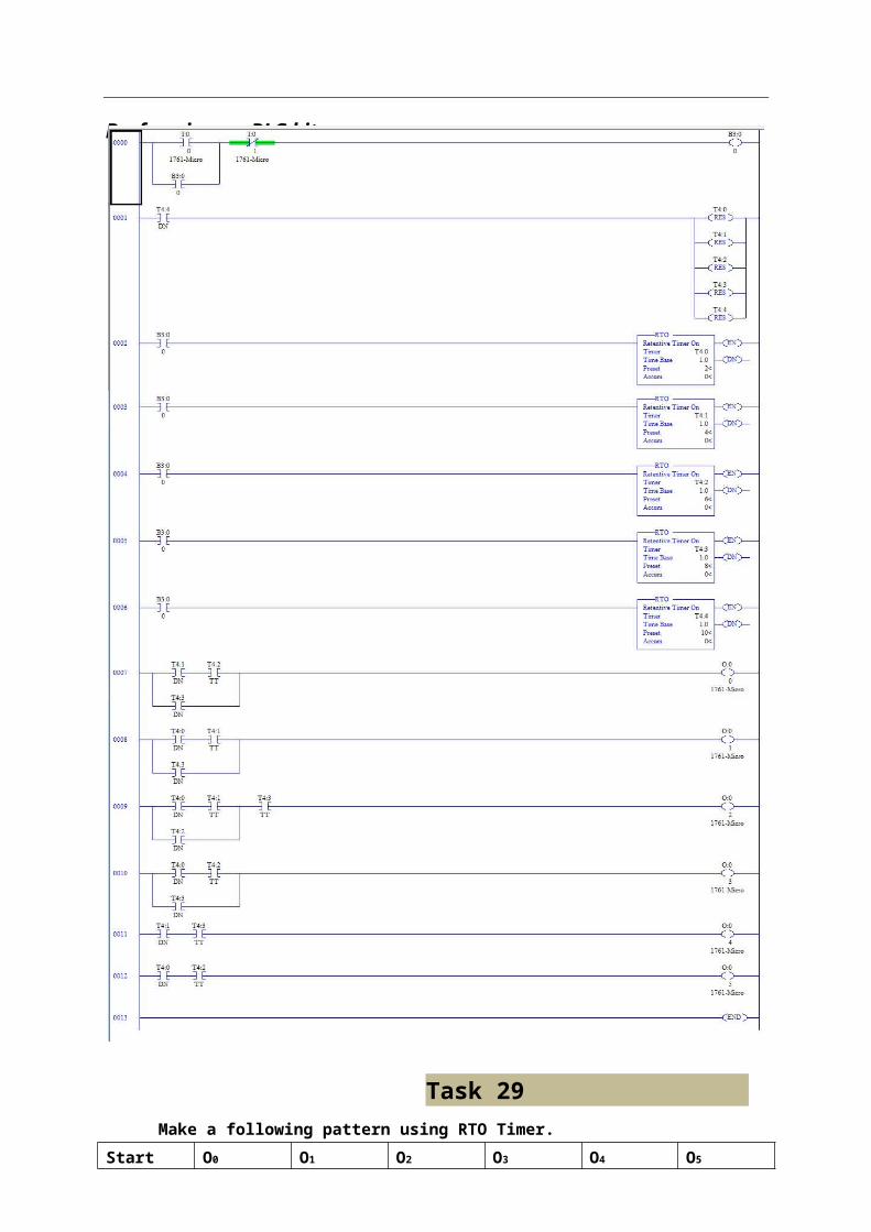
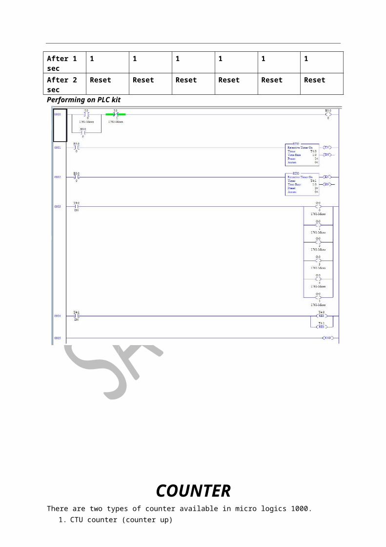
Task 29 Make a following pattern using RTO Timer.
Start O0 O1 O2 O3 O4 O5
After 1 sec 1 1 1 1 1 1
Performing on PLC kitPerforming on PLC kitPerforming on PLC kitPerforming on PLC kitPerforming on PLC kitPerforming on PLC kitPerforming on PLC kitPerforming on PLC kitPerforming on PLC kitPerforming on PLC kitPerforming on PLC kitPerforming on PLC kitPerforming on PLC kitPerforming on PLC kitPerforming on PLC kitPerforming on PLC kitPerforming on PLC kitPerforming on PLC kitPerforming on PLC kitPerforming on PLC kitPerforming on PLC kitPerforming on PLC kitPerforming on PLC kitPerforming on PLC kitPerforming on PLC kitPerforming on PLC kitPerforming on PLC kitPerforming on PLC kitPerforming on PLC kitPerforming on PLC kitPerforming on PLC kitPerforming on PLC kitPerforming on PLC kitPerforming on PLC kitPerforming on PLC kitPerforming on PLC kitPerforming on PLC kitPerforming on PLC kitPerforming on PLC kitPerforming on PLC kitPerforming on PLC kitPerforming on PLC kitPerforming on PLC kitPerforming on PLC kitPerforming on PLC kitPerforming on PLC kitPerforming on PLC kitPerforming on PLC kitPerforming on PLC kitPerforming on PLC kitPerforming on PLC kitPerforming on PLC kitPerforming on PLC kitPerforming on PLC kitPerforming on PLC kitPerforming on PLC kitPerforming on PLC kitPerforming on PLC kitPerforming on PLC kitPerforming on PLC kitPerforming on PLC kitPerforming on PLC kitPerforming on PLC kitPerforming on PLC kitPerforming on PLC kitPerforming on PLC kitPerforming on PLC kitPerforming on PLC kitPerforming on PLC kitPerforming on PLC kitPerforming on PLC kitPerforming on PLC kitPerforming on PLC kitPerforming on PLC kitPerforming on PLC kitPerforming on PLC kitPerforming on PLC kitPerforming on PLC kitPerforming on PLC kitPerforming on PLC kitPerforming on PLC kitPerforming on PLC kitPerforming on PLC kitPerforming on PLC kitPerforming on PLC kitPerforming on PLC kitPerforming on PLC kitPerforming on PLC kitPerforming on PLC kitPerforming on PLC kitPerforming on PLC kitPerforming on PLC kitPerforming on PLC kitPerforming on PLC kitPerforming on PLC kitPerforming on PLC kitPerforming on PLC kitPerforming on PLC kitPerforming on PLC kitPerforming on PLC kitPerforming on PLC kitPerforming on PLC kitPerforming on PLC kitPerforming on PLC kitPerforming on PLC kitPerforming on PLC kitPerforming on PLC kitPerforming on PLC kitPerforming on PLC kitPerforming on PLC kitPerforming on PLC kitPerforming on PLC kitPerforming on PLC kitPerforming on PLC kitPerforming on PLC kitPerforming on PLC kitPerforming on PLC kitPerforming on PLC kitPerforming on PLC kitPerforming on PLC kitPerforming on PLC kitPerforming on PLC kitPerforming on PLC kitPerforming on PLC kitPerforming on PLC kitPerforming on PLC kitPerforming on PLC kitPerforming on PLC kitPerforming on PLC kitPerforming on PLC kitPerforming on PLC kitPerforming on PLC kitPerforming on PLC kitPerforming on PLC kitPerforming on PLC kitPerforming on PLC kitPerforming on PLC kitPerforming on PLC kitPerforming on PLC kitPerforming on PLC kitPerforming on PLC kitPerforming on PLC kitPerforming on PLC kitPerforming on PLC kitPerforming on PLC kitPerforming on PLC kitPerforming on PLC kitPerforming on PLC kitPerforming on PLC kitPerforming on PLC kitPerforming on PLC kitPerforming on PLC kitPerforming on PLC kitPerforming on PLC kitPerforming on PLC kitPerforming on PLC kitPerforming on PLC kitPerforming on PLC kitPerforming on PLC kitPerforming on PLC kitPerforming on PLC kitPerforming on PLC kitPerforming on PLC kitPerforming on PLC kitPerforming on PLC kitPerforming on PLC kitPerforming on PLC kitPerforming on PLC kitPerforming on PLC kitPerforming on PLC kitPerforming on PLC kitPerforming on PLC kitPerforming on PLC kitPerforming on PLC kitPerforming on PLC kitPerforming on PLC kitPerforming on PLC kitPerforming on PLC kitPerforming on PLC kitPerforming on PLC kitPerforming on PLC kitPerforming on PLC kitPerforming on PLC kitPerforming on PLC kitPerforming on PLC kitPerforming on PLC kitPerforming on PLC kitPerforming on PLC kitPerforming on PLC kitPerforming on PLC kitPerforming on PLC kitPerforming on PLC kitPerforming on PLC kit
After 2 sec Reset Reset Reset Reset Reset Reset Performing on PLC kit
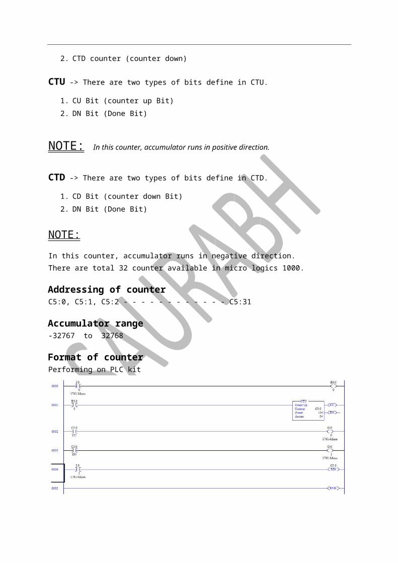
COUNTER There are two types of counter available in micro logics 1000.
1. CTU counter (counter up) 2. CTD counter (counter down)
CTU -> There are two types of bits define in CTU.
1. CU Bit (counter up Bit)

2. DN Bit (Done Bit)
NOTE: In this counter, accumulator runs in positive direction.
CTD -> There are two types of bits define in CTD.
1. CD Bit (counter down Bit) 2. DN Bit (Done Bit)
NOTE: In this counter, accumulator runs in negative direction. There are total 32 counter available in micro logics 1000.
Addressing of counter C5:0, C5:1, C5:2 - - - - - - - - - - - - C5:31
Accumulator range -32767 to 32768
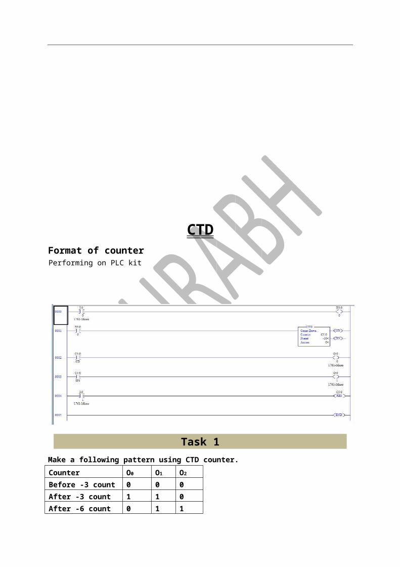
Format of counter Performing on PLC kit
Task 1 Make a following pattern using CTU counter. Counter O0 O1 O2
Before 3 count 0 0 0 After 3 count 1 1 0 After 6 count 0 1 1

Performing on PLC kit
Task 2Make a following pattern using CTU counter. Counter O0 O1 O2 O3
After 3 count 1 0 0 1 After 6 count 1 1 0 1 After 9 count 0 1 1 1
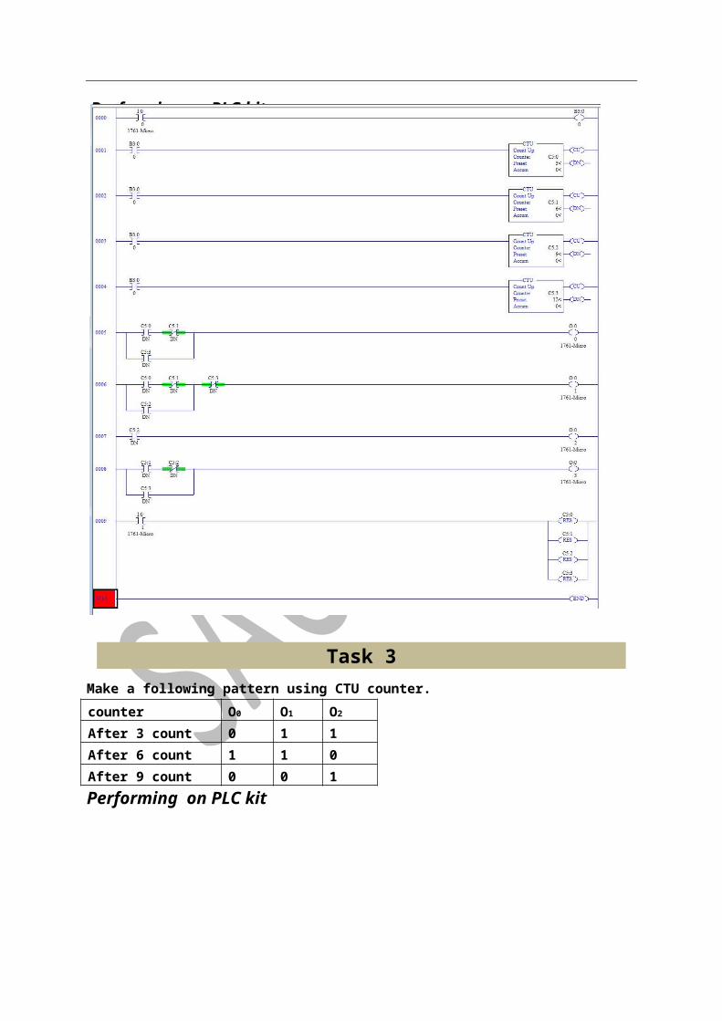
Task 3 Make a following pattern using CTU counter. counter O0 O1 O2
After 3 count 0 1 1 After 6 count 1 1 0 After 9 count 0 0 1 Performing on PLC kit
Performing on PLC kit

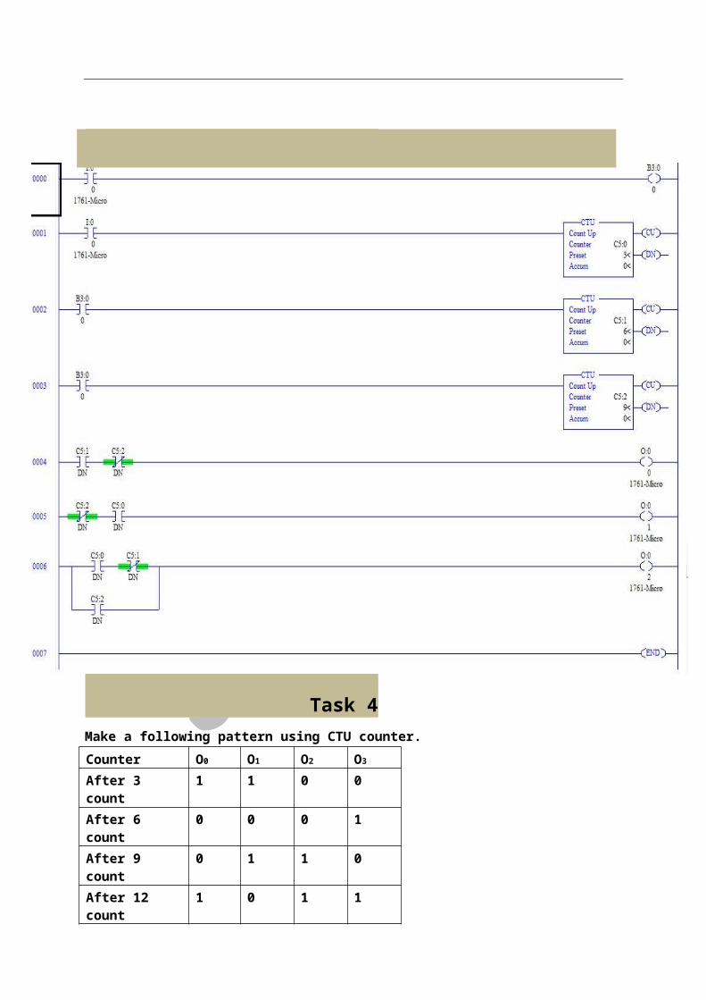
Task 4 Make a following pattern using CTU counter. Counter O0 O1 O2 O3
After 3 count 1 1 0 0 After 6 count 0 0 0 1 After 9 count 0 1 1 0 After 12 count 1 0 1 1 Performing on PLC kit

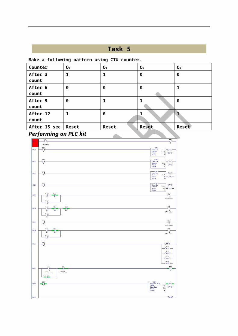
Task 5 Make a following pattern using CTU counter. Counter O0 O1 O2 O3
After 3 count 1 1 0 0 After 6 count 0 0 0 1
After 9 count 0 1 1 0 After 12 count 1 0 1 1 After 15 sec Reset Reset Reset Reset Performing on PLC kit
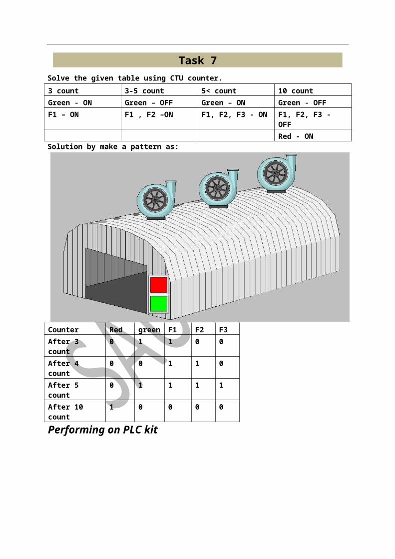
Task 7 Solve the given table using CTU counter. 3 count 3-5 count 5< count 10 count Green - ON Green – OFF Green – ON Green - OFF F1 – ON F1 , F2 –ON F1, F2, F3 - ON F1, F2, F3 - OFF Red - ON Solution by make a pattern as:
Counter Red green F1 F2 F3 After 3 count 0 1 1 0 0 After 4 count 0 0 1 1 0 After 5 count 0 1 1 1 1 After 10 count 1 0 0 0 0
Performing on PLC kit
CTD Format of counter Performing on PLC kit
Task 1 Make a following pattern using CTD counter. Counter O0 O1 O2
Before -3 count 0 0 0 After -3 count 1 1 0 After -6 count 0 1 1 Performing on PLC kit
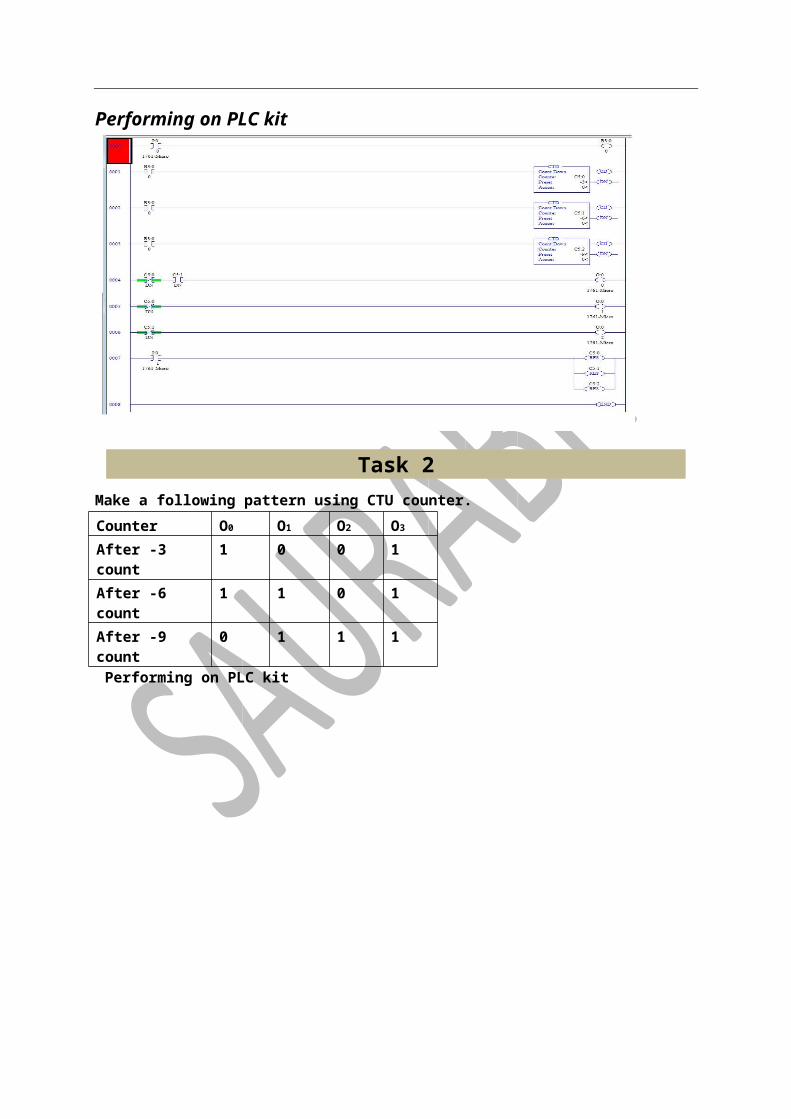
Task 2 Make a following pattern using CTU counter. Counter O0 O1 O2 O3

After -3 count 1 0 0 1 After -6 count 1 1 0 1 After -9 count 0 1 1 1 Performing on PLC kit
Task 3 Make a following pattern using CTD counter. Counter O0 O1 O2
After -3 count 0 1 1 After -6 count 1 1 0 After -9 count 0 0 1 Performing on PLC kit
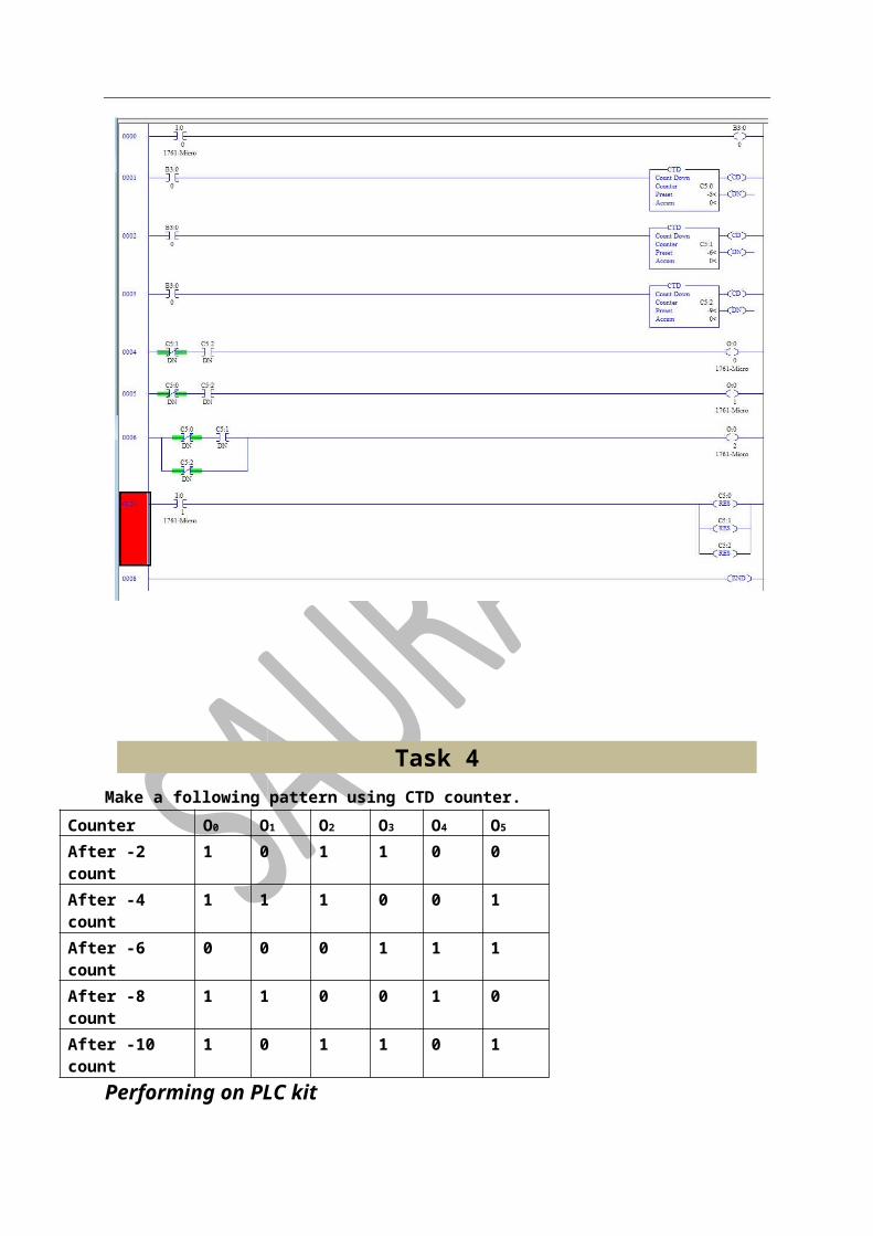
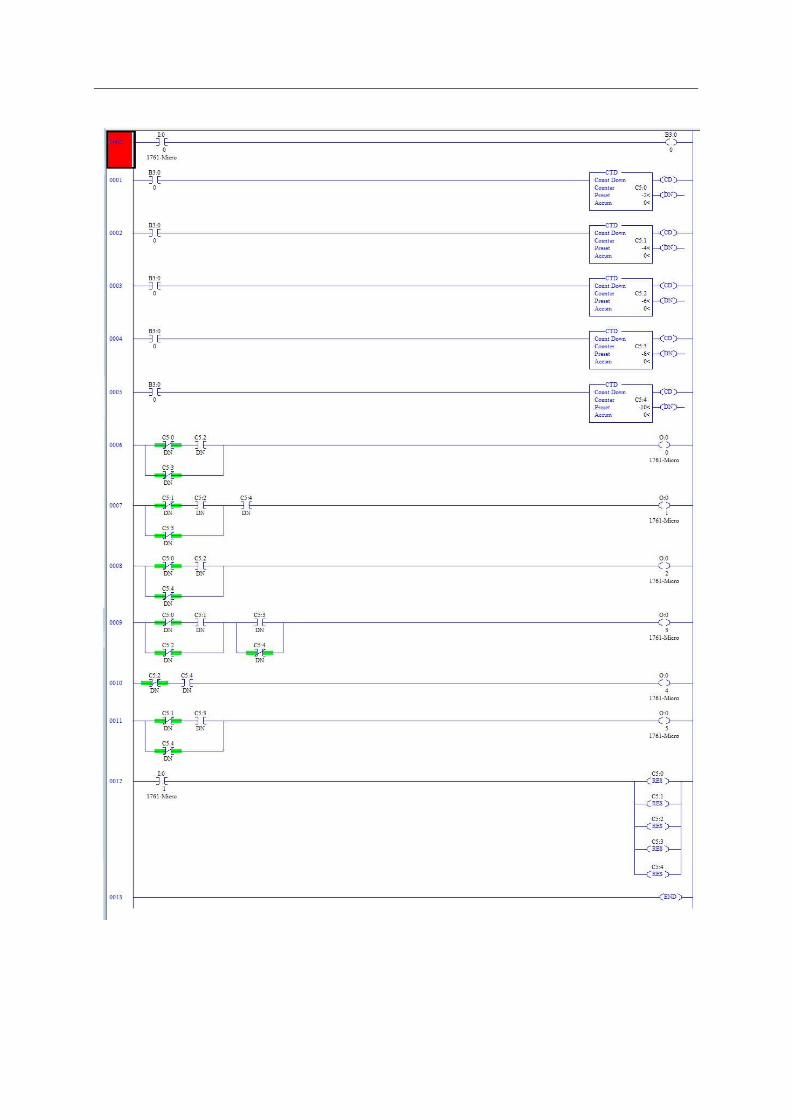
Task 4 Make a following pattern using CTD counter.
Counter O0 O1 O2 O3 O4 O5
After -2 count 1 0 1 1 0 0 After -4 count 1 1 1 0 0 1 After -6 count 0 0 0 1 1 1 After -8 count 1 1 0 0 1 0 After -10 count 1 0 1 1 0 1
Performing on PLC kit

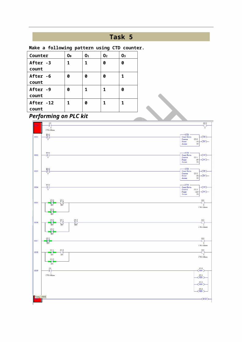
Task 5
Make a following pattern using CTD counter. Counter O0 O1 O2 O3
After -3 count 1 1 0 0 After -6 count 0 0 0 1 After -9 count 0 1 1 0 After -12 count 1 0 1 1 Performing on PLC kit
Task 6
Make a following pattern using CTD counter. Counter O0 O1 O2 O3
After -3 count 1 1 0 0 After -6 count 0 0 0 1 After -9 count 0 1 1 0 After -12 count 1 0 1 1 After 15 sec Reset Reset Reset Reset
Performing on PLC kit
PLC PANNEL COMPONENT
PLC PANNEL COMPONENT & TERMINOLOGY –
1. POWER SUPPLY- DC SUPPLY
o
• SMPS-SWITCH MODE POWER SUPPLY • 24VDC TO 48VDC • 1AMP,2AMP • CONNECTION-
SMPS
L N G +V -V
Ac transformer is used for ac supply
CHANNEL-
AC SUPPLY
IT’S USED FOR MOUNTING ALL COMPONENT
CONNECTOR-
CONNECTOR USED FOR DIVIDING POWER SUPPLY WHICH WILL COME FROM SMPS (SWITCH MODE POWER SUPPLY)
CONNECTION WITH SMPS-
O/P
RELAY –
• 24V DC TO 48V DC • 5PIN,8PIN,11PIN,14PIN • ELECTROSTATIC
• EMFT
LED –
CONNECTOR
I/P V-L N G +V
SMPS
• 24 V DC • 220 V AC
PUSH BUTTONS- RED NC (NORMALY CLOSED) GREEN NO (NORMALY OPEN)
CASING-
CASING IS USED FOR HIDDEN COMPLEXITY OF WIRING
ABOUT PLC -
INPUT MODULE
DIGITAL SINK & SOURCE
ANALOG
SPECIFIC WIRING
SINK CURRENT 1ST FLOW IN FIELD AFTER IN TERMINAL
SOURCE CURRENT 1ST FLOW IN PLC TERMINAL AFTER IN FIELD
NOTE-
90% INPUT WIRING SINK
10% LIMIT SWITCH SOURCE
ANALOGE MODULE-
• IT WORK ON C/N RATING • 0mA TO 4mA
• 0W TO 10W IMPORTANT POINTS
SCAN TIME – 0.2µSEC
MEMORY – RAM, EEPRAM
OPTO COUPLES – PHOTO DIODE AND PHOTO TRANSISTOR WITH NOT
GATE COMBINATION
INPUT OUTPUT
DIODE TRANSISTOR
BIT MEMORY
1 BIT – 0/1
1 BYTE – 8 BIT /0-7
1 WORD – 16 BIT /0-15
2 WORD – BIT 32 / 0-31
1 NIBBLE – 4 BIT /0-3
TYPE OF PLC
Compact plc external I/O card can’t be added
Modular plc external I/O CAN BE ADDED NOTE-
DIGITAL 16 I/O -16 CARD CAN BE EXTEND
ANALOG 8 I/O – 8 CARD CAN BE EXTEND
PLC PANNEL DISIGNING & WIRING FROM MY GROUP [MAKING ALLEN BRADLY PLC PANNEL] GROUP MEMBER – SAURABH GEHLOT
PARKASH CHAND
KAILASH SONI
RAM SINGH SODHA
MOHD.JAVED RAO
STEPS FOR MAKING PANNEL DESIGNING
STEP -1 MAKING A STEAL STRUCTURE OF PANNEL –
(IT’S DOEN BY WELDER MAN OR IRONWORKER)
DRILLING ACCORDING TO I/O
STEP-2 COLOURING THE PANNEL

STEP-3 ARRANGE DEVICES ACCORDING WIRINING
I-4 I-3 I-2 I-1 I-0
WIRING CONNECTION – (LOGIC)
SMPS ALLN BRADLY PLC
NC,SENS.) O/P MCB CONNECTOR RELAY I/P(NO&
-BACKWORD IMAGE
CONNECTION DIAGRAM-(LOGIC)
PANNEL CONECTION FROM GROUP –
FIRST CONNECTION OF INPUT (TOGGLE BUTTON) &
OUTPUT TERMINAL
INFORNT CONNECTION OF MCB, SMPS, CONNECTOR, RELAY& ALLEN BRADLY PLC
-

ALL CONNECTION COMPLETED -

PANNEL DESIGNING IS COMPLETED
PARLE – G PRODUCT LIMITED –
LOCATION AJMER EXPERIENCE –
• LEARN ABOUT BISCUIT MAKING • HIGHLY AUTOMATION SYSTEM • SAFLY WORKING ENVIORMENT
VISIT-2 AJMER GASES
LOCATION AJMER
EXPERINCE-
• HOW OXIGEN GASES FILLING IN CONTAINERS CYLENDER
• MANUALY WORKING SECTION-1

KNOWLEDGE ABOUT AUTOMATION PROCESS WORKING ON SCADA SOFTWARE(INTOUCH) KNOWLEDGE ABOUT WORKING OF PLC LEARNING OF LADDER PROGRAMMING OR
WORKING ON FOLLOWING PLC- - ALLEN BRADLY - MITSUBISHI ELECTRIC - SIMENS S7-1200