please note that the illustrations, colors and fonts may
TRANSCRIPT

1
PRECAUTIONSIMPORTANT! PLEASE READ
BEFORE PROCEEDING.Following the important precautions below will help ensure you
many years of trouble free use from your CS1x.
LOCATION• In order to avoid causing serious damage to
the CS1x, do not expose it to direct sunlight,high temperatures, excessive humidity,excessive dust or strong vibration.
• Always place the CS1x on a solid surface suchas a keyboard stand or a sturdy table or desk.
POWER SUPPLY• Turn the power switch off when the CS1x is
not in use.
• Use only the supplied PA-3B or an equivalentAC power adaptor. Use of an incompatibleadaptor may result in irreparable damage tothe CS1x, and could even pose a seriousshock hazard.
• The power adaptor should be unpluggedfrom the AC outlet if the CS1x is not to beused for an extended period of time.
• Unplug the CS1x during electrical storms.
• Avoid plugging the CS1x into the same ACoutlet as appliances with high powerconsumption such as electric heaters orovens. Also avoid using multiple-plugadapters since these can result in reducedsound quality and possibly even damage tothe instrument.
UNPLUG ALL INSTRUMENTSWHEN MAKING CONNECTIONS
• To avoid causing damage to the CS1x andother devices to which it is connected, suchas a sound system or MIDI instruments, turnoff the power and unplug all related devicesprior to connecting or disconnecting audioand MIDI cables.
ELECTRICAL INTERFERENCE• Avoid using the CS1x near televisions, radios
or other devices which generateelectromagnetic fields, since this may causethe CS1x to malfunction, and possiblygenerate interference noise in the otherdevices.
BACK-UP BATTERY• The CS1x contains a special long-life battery
that retains the contents of its User memorywhen the power is turned off. The back-upbattery should last for several years. When itneeds to be replaced, the message "BatteryLow" will appear in the display when thepower is turned on. When this happens, havethe backup battery replaced by qualifiedYamaha service personnel. Do not attemptto replace the backup battery yourself.
HANDLING AND TRANSPORT• Always handle the CS1x with care. Physical
shocks caused by dropping, bumping, orplacing heavy objects on it can result inserious damage to the CS1x.
• Never apply excessive force to the controls,connectors or other parts.
• Disconnect all cables before moving theCS1x. Always unplug cables by gripping theplug firmly, and not by pulling on the cable.
CLEANING• Never use chemical solvents or thinners to
clean the CS1x, since these will damage thefinish or dull the keys. Wipe the instrumentclean with a soft, dry cloth. If necessary, usea soft, clean cloth slightly moistened with a
diluted, mild detergent. Then wipe theinstrument thoroughly with a dry cloth.
• Avoid placing vinyl objects on top of theinstrument, since vinyl can stick to anddiscolor the surface.
DATA BACKUP• Yamaha recommends that you regularly save
your music data using an external MIDI datastorage device such as the Yamaha MDF2MIDI Data Filer. Yamaha cannot be heldresponsible for the accidental loss of CS1xdata.
SERVICE AND MODIFICATION• The CS1x contains no user serviceable parts,
so never open the case or tamper with theinternal circuitry in any way. Doing so mayresult in electrical shock or damage to theinstrument. Refer all servicing to qualifiedYamaha service personnel.
IMPORTANT NOTE
Yamaha cannot be held responsible for damageto the CS1x resulting from improper handlingor operation, or for the accidental loss of CS1xdata.
NOTICES
• The company names and product names inthis owner's manual are the trademarks orregistered trademarks of their respectivecompanies.
• The LCD screens as illustrated in this owner'smanual are for instructional purposes, and mayappear somewhat different from the screenswhich appear on your instrument.

2
In the beginning, there was the knob…
And the knob was good. Great, in fact.You could just reach out and grab it. Turn it left. And turn it right.
Interact with it in realtime.And there were knobs of all kinds. Knobs for changing the attack
and release times of a sound. Knobs for setting the cutoff filter andresonance. And knobs for controlling many other aspects of analogsynthesizer sounds.
By twisting a knob one way and another, a vast, practically endlessvariety of electronic sounds could be called forth. Fat sounds. Strangesounds. Beautiful sounds. Magical sounds.
It was the 1960s, and such was the power of the knob that musicwas changed forever.
And the term synthesizer became a household word.
But the knob was not perfect…
From the start the knob was brilliant and easy to grasp. It put themusician in complete control of the sound. And opened up a wholenew world of sonic exploration.
It was the 1970s, and some of the greatest recordings in music historywere being made. Analog "synths" were finding their way into the stages,studios and professional composing suites of the world.
But as simple, straightforward and powerful as analog synths were,they were also for the most part priced out of reach of the strugglingmusician. Plus they tended to be sensitive to slight fluctuations in electriccurrent which frequently wreaked havoc with pitch, thus making tuninginherently unstable.
And there was no reliable way to save panel settings and originalsounds except for tediously scrawling lists and notes with pencil andpaper.
Surely there must be a better way.Engineers the world over went to work searching for a better way,
and great strides were made in the development of more stable, lowercost, and more convenient technologies.
A breakthrough in electronic sound synthesis was imminent.
Then came the miracle of digital…
The beginning of the 1980s saw breakthroughs in digital synthesizertechnology which was to once again revolutionize modern music.
Musicians everywhere embraced affordable new technologies likeFM, which could accurately reproduce the sound characteristics ofacoustic and other instruments, and AWM (PCM), which relied on"samples" of actual instrument sounds to produce an amazing wealthof musical textures and sonic options.
The new spate of digital synthesizers were—on the outside—muchmore streamlined than analog synths, sporting a minimal array of buttonsand a display screen which provided information about each feature.
Overnight the knob was rendered virtually obsolete.Unstable tunings were a thing of the past. Memory was the future.Digital synths were—on the inside—more loaded than ever, as
hundreds of amazing acoustic and electronic sounds, or voices, couldbe stored and recalled at the touch of a button. Scores of new and excitingfeatures were available. Entire panel settings and configurations couldalso be stored for instant recall.
It was the digital revolution that made MIDI, GM, XG, sequencing,sampling, looping, multitimbral play, DSP effects and many otherbreakthroughs in electronic music technology possible.
Developments that have changed forever the way we teach, compose,
Introduction
2

3
on the panel.A collection of six rotary Sound Control Knobs are irresistible to the
touch—and provide instant sonic results when turned.Between the Sound Control Knobs, the clearly labeled panel switches,
and the back lit LCD, the current status of the CS1x is always crystalclear.
The numeric keypad and other buttons—including Scenes, or"snapshots" of knob positions—give you quick and easy access to anyparameter or setup you need, the moment you need it.
As such, the CS1x is an unprecedented realtime performanceinstrument.
The hundreds of great sounding AWM2 (Advanced Wave Memory2) instrument voices (created from high quality recordings of actualinstrument and other sounds), three digital effects units (with 11 Reverb,11 Chorus and 43 Variation type effects) and scores of other parameterscan be configured in an almost unlimited variety of ways and stored inmemory for instant recall.
Performances, or complete configurations of up to four Layers(voices) playing simultaneously, plus effect and other parameters, andMultis, or a configuration of up to 16 Parts and other parameters formultitimbral play (using an external sequencer or computer), provide aunique array of options which make the CS1x a handy synth for literallyany type of music situation.
Thirty-two notes of polyphony ensure that you always have enoughavailable notes to play even the most demanding arrangement.
The on-board arpeggiator which can generate various types ofautomatic arpeggios or be controlled by an external MIDI clock providesan extremely useful tool for spicing up your masterpieces—or settingthe dance floor on fire.
Go forth and multiply…
As simple—yet powerful—as the CS1x is on its own, it has alsobeen specially engineered to easily fit right into any type of expandedmusic system you wish to create.
General MIDI (GM) compatibility makes the CS1x an idealmultitimbral tone generator for accurately playing any of the manyStandard MIDI File or other commercially available GM music data usingan external sequencer.
XG compatibility makes the CS1x completely state of the art—conveniently able to take advantage of the expanded sound andexpressive capabilities that this exciting new format will offer in thecoming months and years.
A TO HOST terminal and HOST SELECT switch provides for directinterface with either PC and Macintosh computers, thus enabling youto easily jump right into the "desktop music" revolution without theneed for any additional peripheral interfacing equipment.
If you're a first-time synthesizer owner, the CS1x lets you expandyour music system at your own pace.
First you might want to add an affordable Yamaha QY seriessequencer and take advantage of the CS1x's powerful multitimbralcapabilities. With a QY sequencer you can record and play back up to16 music "parts", each on an independent MIDI channel—just like amultitrack recorder, but with virtually unlimited editing capabilities.
Next you might want to add the compact, low-cost Yamaha SU10sampler which lets you capture music phrases and other sounds to addan entirely unique dimension to your music.
Finally you might want to add a computer which will let you takeadvantage of the many different types of music software products nowavailable plus those yet to come.
With the CS1x at the heart of your system, you're ready to growyour own unique music system and take your musical capabilities as faras you want—naturally.
perform and listen to music.Global design standards ensured that music hardware and software
products made by different manufacturers could work togetherseamlessly.
But alas, digital did not create a perfect world.
Chaos reigned over the land…
As convenient, dynamic and accessible as digital synthesis was, stillit was not perfect. It had certain limitations, though different ones thananalog synthesis.
Streamlined panel layouts and the demise of the knob meant thatall those hundreds of great new features had to be organized and stackedin pages and subpages of hidden menus—which might mean severalpresses of one or more buttons just to find a feature, and several moreto actually manipulate it.
And the steep learning curve of many digital synthesizers became alegend unto itself. Alarmingly, the synth was on its way to becoming athing of science, rather than an intuitive musical instrument.
It was, therefore, inevitable that many would come to mournnostalgically for the days of simplicity—for the knob. For those warm,fat, wonderful analog sounds. For fewer hidden features.
And for a simpler, easier to use electronic instrument.There was a definite need for an analog-style digital synthesizer
that would have intuitive knobs plus all the benefits of digital memoriesand other convenient—especially interactive—features.
One that could satisfy even the most die-hard advocate of analog ordigital synthesis.
A perfectly versatile synthesizer as attractive to first-time synthowners as to desktop music hobbyists, serious amateurs, and evenseasoned professionals.
A powerful stand-alone performance instrument with hot dancemusic and other versatile voices, as suited for the cutting edge as for theclassics.
An ideal multitimbral MIDI component which could fit right intoeven the most sophisticated expanded system.
One with extremely modest pricing for such powerful utility.It was only a matter of time before the thunder of analog would
unite with the lightning of digital to once again challenge conventionand ultimately change the landscape of music possibilities yet once more.
And Yamaha heard their cries…
Fortunately Yamaha recognized that something new and significantmust be created to bring together the best of both analog and digitalworlds.
The result was the Yamaha Control Synthesizer CS1x.The CS1x takes the best of analog—simplicity of use, natural
interactivity, thick sound, and, of course, the knob—and unites it withthe best of digital—reliable pitch, plenty of memory, one-touch settingreconfigurations, hundreds of voices, MIDI, and much, much more—to begat a truly unique "control" synthesizer.
One with all the familiar concepts loved by both analog and digitalafficianados. One destined to satisfy even the most meticulous purist ineach camp.
Nothing to hide…
Perhaps the most striking—certainly refreshing—aspect of the CS1xControl Synthesizer is the way it wears its heart on its sleeve.
What you see is what you get: all features are self-evidently displayed3

4
CS1x MAINFEATURES
The CS1x is specially designed with an intuitive, interactive user interfacethrough lots of dedicated panel controls and sound editing features whichcan easily be manipulated in realtime during performance. Main featuresinclude:
• 6 Sound Control Knobs for direct access to key parameters of the currently
selected voice as you play, and 2 Scene memories for instant recall of
specified Sound Control Knob positions. You can use the Modulation
Wheel or a connected Foot Controller for continuous changes between
Scene 1 and Scene 2 parameter values.
• 480 GM- and XG-compatible AWM2 instrument voices and 11 drum
voices, or kits, in Multi Play mode. Additional voices are available in
Performance mode which can be assigned to the Performances.
• Performance mode with complete configurations of Layers (4 voices either
stacked or in sophisticated keyboard and velocity splits), digital effects
and other parameters. There are a total of 128 Preset Performances and
128 User Performances.
• Multi Play mode for multitimbral play of up to 16 different Parts (across
16 MIDI channels; when using an external sequencer), with 32-note
polyphony. TO HOST terminal and HOST SELECT switch allow direct
interface with IBM PC/AT or Apple Macintosh computers.
• 3 independent DSP digital effect units which can be used simultaneously—
Reverb (11 types), Chorus (11 types) and Variation (43 types).
• Arpeggiator with 30 types of arpeggiated chords and 10 timing subdivisions.
The Arpeggiator's tempo can also be controlled by an external MIDI
clock.

5
CONTENTS
The CS1x At A Glance .....................................6
Getting Started ............................................9
How The CS1x Generates Sound ................... 12
CS1x Main Operating Modes ........................ 14
Feature Reference ............ 20Performance Mode .....................................20
Common Edit 1 ........................................ 22
Common Edit 2 ....................................... 25
Layer Edit 1 ............................................. 27
Layer Edit 2 .............................................30
Layer Edit 3 ............................................. 31
Layer Edit 4 ............................................. 33
Multi Play Mode.......................................... 36
Utility Mode ...............................................40
Store Mode .................................................44
Factory Settings .........................................46
Appendix............................. 47Digital Effects ............................................ 47
About MIDI ................................................. 53
Specifications ............................................. 57
Troubleshooting ......................................... 58
Error Messages ........................................... 59
Index..........................................................60

6
THE CS1x AT AGLANCE
ATTACK
PHONES L/MONO
OUTPUT
R DC IN POWER FOOTVOLUME
FOOTCONTROLLER
FOOTSWITCH
TO HOSTINPUT HOST SELECT IN OUT
MIDI
THRU
AMP EGRELEASE ASSIGN 1/DATAVOLUME
CUTOFFFILTER
RESONANCE ASSIGN 2
2
MW/FC
1
SCENE
ARPEGGIO HOLD SHIFT
OCTAVEPART/LAYER/
+
PRESET USER
VWX
PROGRAM
+
PERFORMANCE STOREMULTI
PRESET USER ARPEGGIATOR
UTILITY 7
YZ'
8
&*
9MNO
4
PQR
5
STU
6DEF
1
GHI
2
JKL
NO/QUICK PC
YES
3ABC
0
SPACE
ENTER
PERFORMANCE MULTI
DEMO
STORE UTILITY
TYPE
BANK
P BENDRANGE
NOTESFT
ATKTIME
ATKTIME
MASTERTUNE
TEMPOARPEGGIATOR PERFORM
LEVELEFECT
PROGRAM
SYSTEM MIDI ASSIGN
PMOD
DETUNE
DCYTIME
DCYTIME
KBDTRANS
SUBDIVIDE
VOLUME
FMOD
REVTYPE
CUTOFFFC PORTA
VEL ASSIGN2
LFO
PEG
CHOTYPE
VARIEF
VARITYPE
SWITCH
VARIPARAM
TIME
VARIDATA
MWFMOD
LIMITLOW
TUNE
AEG
FEG
NOTE
SUSLEVEL
SUSLEVEL
VELCURVE
PAN
CUTOFF
LIMITHIGH
RELTIME
RELTIME
VELFIX
REVSEND
LIMITLOW
AMOD
INITLEVEL
TRANSCH
CHOSEND
LIMITHIGH
PMOD
ATKTIME
EFFECT
RCVCH
VARISEND
OFFSET
FMOD
ATKLEVEL
DEVICENO
CUTOFFFILTER
DEPTH
WAVE
DCYTIME
LOCAL
REZ
PARAM
SPEED
RELTIME
BULKDUMP
PERFORMNAME
POLY/MONO
ASSIGN1PARAM
DATA
PHASEINIT
RELLEVEL
CTRLNO
COMMON
LAYER
UTILITY
PITCH MODULATION
FrontPanel
! VOLUMETurn this knob to set the properlistening level whether usingheadphones or amplified speakers.
" SOUND CONTROLKNOBS
The six Sound Control Knobs giveyou direct access to key parametersof the current ly se lectedPerformance/voice. Turning anySound Control Knob to the left orright will offset the parameter valuesaccordingly (left for negative values,right for positive values) andproduce an immediate result; a letter"E" will appear next to thePerformance number in the LCD toindicate the original voice has beenedited. Each knob has a centerdetent which represents the originalvalue of the parameter.
• ATTACK (Knob 1) - This knobcontrols the initial attack time of thevoice. Turn it left for a faster attack
time; turn it right for a slower attacktime. (See page 30)
• RELEASE (Knob 2) - This knobcontrols the release time of the voice.Turn it left for a shorter release time;turn it right for a longer release time.(See page 32.)
• ASSIGN 1/DATA (Knob 3) - Thisknob has two functions. As anASSIGN 1 knob, you can assign oneof 28 parameters—includingPerformance Volume, ArpeggiatorTempo or Type, Portamento Time,and others—to control by turning it(see page 26). As a DATA entry knob,you can use it to quickly change theedit value of the currently selectededit parameter.
• CUTOFF (Knob 4) - This knobdetermines the cutoff frequency ofthe filter, or the frequency pointabove which other frequencies arefiltered out. Turn it left for a deeper,more rounded tone; turn it right fora thinner, brighter tone. (See page25.)
• RESONANCE (Knob 5) - This knobdetermines the amount of filterresonance or emphasis of the cutofffrequency. Turn it left to produce arelatively flat response; turn it rightto add overtones and make thesound more resonant. (See page 34.)
• ASSIGN 2 (Knob 6) - This knob canbe used to control any one of 28parameters which you can assign toit—including Volume, Note Shift,Pan, Chorus Send, and others. (Seepage 29.)
# SCENE 1 & 2Each Performance has two Scenememories which remember specificpositions of the six Sound ControlKnobs. (See page 16.)
• Simply press SCENE 1 or SCENE 2to instantly recall the specifiedsettings. An LED beside each SCENEbutton will light to indicate whichScene is currently active. You canstore your own Scenes in advanceusing Store mode. (See page 44.)
• By holding one SCENE button andthen pressing the other SCENEbutton, both LED's will light,indicating that you can use theModulation Wheel or a connectedFoot Controller for realtimecontinuous parameter changesbetween one Scene and the other.(See page 45.)
$ ARPEGGIATORPress this button to activate the on-board Arpeggiator, which lets youcreate automatic arpeggios simplyby playing a chord. An indicator willappear in the lower right area of theLCD when the Arpeggiator is on.(See page 22.)
• There are various Arpeggiator Typesa n d A r p e g g i a t o r T i m i n gSubdivisions. These, plus theArpeggiator Tempo, can be specifiedwith the Common Edit 1 menuparameters. (See page 23.)
• Pressing this button while holdingSHIFT will "hold" the arpeggiatedchord, or make it continue playingeven when you release the keys.Pressing this button again stops theArpeggiator. (See page 23.)
• An Arpeggiator Split function lets yousplit the keyboard at C3; the chordsyou play to the left of the split pointwill create arpeggiated chords, andthe notes and chords you play to theright of the split point will play asnormal. (See page 23.)
7
% SHIFTThis button lets you transpose theoctave up or down as well asactivate the Arpeggiator Hold andSplit functions. (See page 23.)
• To transpose the octave, hold theSHIFT button and press [–] (octavedown) or [+] (octave up)—locateddirectly beneath the SHIFT button.(See page 15.)
& PART/LAYER [–]/[+]These buttons let you select one ofthe four Layers in Performancemode (see page 14), or one of the16 Parts in Multi Play mode (seepage 17). Which Layer or Part iscurrently selected will be indicatedin the lower right area of the LCD.
' PRESETIn Performance mode, press thisbutton to activate the bank of 128Preset Performances. (See page 20.)
( USERIn Performance mode, press thisbutton to activate the bank of 128User Performances. (See page 20.)
) PROGRAM [–]/[+]Press one of these to step up ([+]) ordown ( [– ] ) th rough eachPerformance (in Performance mode)or voice (in Multi Play mode), oneat a time. (See page 20.)
* BACK LIT LCDThe LCD provides various types ofinformation which clearly indicatesthe current operating status of theCS1x, depending on which modeor other button on the front panelthat you press.
+ NUMERIC KEYPADThe numeric keypad has severalfunctions, depending on thecurrently selected mode.
• In Performance mode or Multi Playmode, you can use it to select aspecific Performance number orvoice number—by punching in thedesired number (1~128), thenpressing the ENTER button. (See page20.)
• In Quick Program Change mode,you can use it to select a specific
Performance (Performance mode)or voice (Multi Play mode) withinthe currently designated group of10—by simply punching in the lastdigit (0~9) of the desiredPerformance or voice number. (Seepage 21.)
• When editing parameters, you canuse it to quickly select a specificvalue—by punching in the desirednumber, then pressing ENTER. (Seepage 20.)
• When naming a User Performance,you can use it to select the letters ofthe name, as indicated above eachbutton. (See page 24.)
, [–]/NO/QUICK PCThis button has three functions.
• As a [–] button, you can use it toenter negative values when editingparameters using the numerickeypad. Press it before entering thenumber, followed by ENTER.
• In Performance mode or Multi Playmode, press it once to engage theQuick Program Change function.The hundredth and tenth digits ofthe Performance or voice numberwill be shown as bold charactersto indicate they are fixed whenQuick Program Change is active.Press the button again to turn offQuick Program Change. (See page21.)
• In Store mode, this button lets youdecline (NO) the store operation ifyou change your mind.
- ENTER/YESThis button has three functions.
• When selecting a Performancenumber (Performance mode) orvoice number (Multi Play mode)using the numeric keypad, youmust press ENTER to activate thechange. (See page 20.)
• When designating edit parametervalues using the numeric keypad,you must press ENTER to activatethe change. (See page 22.)
• In Store mode, this button lets youconfirm (YES) the store operation.(See page 44.)
. MODE SELECTSWITCHES
Press one of these to select thecurrent operating mode.
• PERFORMANCE - In Performancemode you can choose any of thePreset or User Performances, plusperform editing operations using theEdit Parameter Rotary Switch andParameter Value UP/DOWNbuttons. Press PERFORMANCE toenter Performance mode fromanother mode, or to reselect thePerformance select screen in theLCD after performing an editoperation in Performance mode.(See page 20.)
• MULTI - Press this button to enterMulti Play mode, which lets youdesignate up to 16 Parts formultitimbral play when using anexternal sequencer. Parameterswhich can be edited in Multi Playmode are printed in a row directlyabove the Parameter Value UP/DOWN buttons. (See page 36.)
• STORE - This button lets you storeUser Performances. as well asScenes. (See page 44.)
• UTILITY - Press this button to accessthose "system" parameters whichaffect the CS1x as a whole—such asMaster Tune, MIDI Transmit andReceive Channel numbers, LocalOn/Off, etc.—as printed directlybelow each Parameter Value UP/DOWN button. (See page 40.)
/ EDIT PARAMETERROTARY SWITCH
Turn this knob to select one of thesix menus of edit parameters inPerformance mode.
• COMMON - The Commonparameters (Common Edit 1, 2menus) are those parameters whichapply to the entire currently selectedPerformance; i.e., it doesn't matterwhich Layer is currently selected,since common parameters (exceptfor Portamento) apply to all layersequally. (See page 14.)
• LAYER - The Layer parameters (LayerEdit 1, 2, 3, 4 menus) are thoseparameters which affect only thecurrently selected Layer (1~4, asdesignated by the PART/LAYERbuttons) in a Performance. (See page14.)
0 PARAMETER VALUEUP/DOWN BUTTONS
These ten buttons are used to accessspecific parameters in Performance,Multi and Utility modes, as well aschange the values of the currentlyselected edit parameter.
• PERFORMANCE MODE - Afterselecting an Edit menu row with theEdit Parameter Rotary Switch, pressthe Parameter Value UP/DOWNbutton located beneath the desiredparameter once to access theparameter. The parameter name andcurrent value will appear in the LCD.Then press [UP] or [DOWN] toincrease or decrease the currentparameter value as desired. (Seepage 14.)
• MULTI PLAY MODE - Simply pressthe Parameter Value UP/DOWNbutton located beneath the desiredparameter as printed on the panel,directly above each button. Theparameter name and current valuewill appear in the LCD. Then press[UP] or [DOWN] to increase ordecrease the current parameter valueas desired. (See page 17.)
• UTILITY MODE - Simply press theParameter Value UP/DOWN buttonlocated above the desired parameteras printed on the panel, directlybelow each button. The parametername and current value will appearin the LCD. Then press [UP] or[DOWN] to increase or decrease thecurrent parameter value as desired.(See page 40.)
1 PITCHThe Pitch Wheel lets you bend thepitch up or down as you play. It isspring-loaded to automaticallyreturn to center position when youlet go of it. In Performance modeyou can designate the Pitch BendRange in the Common Edit 2 menu.(See page 25.)
2 MODULATIONThe Modulation Wheel lets youapply or set a designated amount ofvibrato or tremolo. You can set it toaffect filter cutoff, filter modulation,pitch modulation (Common Edit 2menu, see page 25), as well as othercontrollable parameters. (see page43.)

8
# TO HOSTThe TO HOST terminal lets youconnect the CS1x directly to a hostcomputer which does not have aMIDI interface. (See page 10.)
$ INPUTConnect an external audio source(such as a keyboard, or CD player)here using either a stereo or monomini plug, in order to mix its audiosignals with the CS1x's voices, foroutput from the CS1x without theneed for an external mixer.
% FOOTSWITCHAn optional Yamaha FC4 or FC5footswitch connected to this jackcan be used to control hold on/off,portamento on/off and others,determined by the Assign ControlChange Number setting in Utilitymode. (see page 43.)
& FOOT CONTROLLERAn optional Yamaha FC7 or FC9foot controller connected to this jackcan be used for control of filtermodulation, filter cutoff, and the
RearPanel
! MIDIMIDI IN, OUT and THRU terminalslet you connect other MIDI devicessuch as a MIDI keyboard, tonegenerator, sequencer, or computerwith a MIDI cable. (Set the HOSTSELECT switch to MIDI when usingthe MIDI terminals.) MIDI IN is forinput of MIDI data. MIDI OUT isfor output of MIDI data and for datadumps to another CS1x or MIDI datastorage device. MIDI THRU is for"daisy-chain" connection ofadditional MIDI instruments, as theMIDI data received at the CS1x'sMIDI IN terminal is passed alongunchanged to the CS1x's MIDITHRU terminal. (See page 9.)
" HOST SELECTThe HOST SELECT switch lets youdesignate the type of host computer.(See page 10.) Set it to MIDI fornormal MIDI transmission andreception when a host computer isnot connected.
Variation effect (Common Edit 2menu, see page 26), as well as theControl Change Number. (see page43.)
' FOOT VOLUMEAn optional Yamaha FC7 or FC9foot controller connected to this jackcan be used to regulate overallvolume.
( POWERPress this switch to turn the CS1xon and off.
) DC INConnect the supplied Yamaha PA-3B Power Adaptor here .(CAUTION: Do not attempt to usean AC adaptor other than theYamaha PA-3B or equivalent, sincethe use of an incompatible adaptormay cause irreparable damage tothe CS1x, and may even pose aserious shock hazard.)
MIDI
OUTTHRU IN MIDI Mac TO HOST INPUT SWITCH CONTROLLER
ASSIGNABLE
FOOT FOOTVOLUME
FOOTON OFF DC IN R L/MONO
OUTPUT PHONESPOWERPC-2 PC-1
HOST SELECT
THE CS1x AT A GLANCE
* OUTPUTThe stereo OUTPUT jacks let youconnect the CS1x to an externalstereo amplifier/speaker system.When using a mono system,connect it to the L/MONO jack.
+ PHONESThe PHONES jack lets you connecta set of stereo headphones forprivate listening.

9
GETTING STARTEDSetting Up Your CS1x
The CS1x With An ExternalSequencerThe illustration below shows how to use the CS1x with a Yamaha QYseries sequencer, which lets you take full advantage of the CS1x'smultitimbral capability to play up to 16 different musical instrument Partsat once.
You will need MIDI cables to make the proper connections.
1. Connect a MIDI cable from the CS1x's MIDI OUT terminal to thesequencer's MIDI In terminal, and connect another MIDI cable fromthe CS1x's MIDI IN terminal to the sequencer's MIDI Out terminal.
2. Set the HOST SELECT switch to MIDI.
QY300 etc...QY300 MUSIC SEQUENCER
MIDI IN
MIDIOUT
MIDI OUT
MIDI INHOST SELECT
PC-2 PC-1MIDI Mac
CS1x
In this case, the notes you play on the keyboard will be sent as MIDI noteevent data to a specified MIDI channel of the sequencer. By selectingdifferent channels, you can record each Part independently, while listeningto those Parts you've already recorded.
When recording Parts to an external sequencer, you need to turn thekeyboard Local setting to OFF (see page 42). When keyboard Local isturned off, the notes you play on the keyboard will not sound the CS1x'sinternal tone generator, but note and other performance event data willstill be sent from the MIDI OUT terminal.
Since the CS1x's internal tone generator will respond to note and otherdata it receives at the MIDI IN terminal, the notes you play on the keyboardwill be sent to the sequencer, then "echoed back" to the CS1x to play oneof the 16 Parts (depending on the current MIDI channel assignment).
For details about assigning CS1x MIDI channels, see page 41. For detailsabout assigning MIDI channels and other settings for the external devicessuch as a sequencer, consult the owner's manual of each.
The Control Synthesizer CS1x literally comes ready to play right out ofthe box.
Connect the supplied PA-3B DC power adaptor to the CS1x's DC INconnector on the rear panel. Then connect the adaptor to the nearestelectrical outlet.
Before switching on the power, connect any peripheral devices such asamplified speakers or MIDI instruments.
There are many ways to incorporate the CS1x into a simple or expandedmusic system. Below are a few examples to get you started.
CAUTION
• Do not attempt to use an AC adaptor other than the PA-3B. Use of anincompatible adaptor may result in irreparable damage to the CS1x, andcould even pose a serious shock hazard.
• Be sure to disconnect the power adaptor from the electrical outlet whenthe CS1x is not in use.
The CS1x By ItselfAt the simplest level, all you need to do is connect stereo headphones tothe PHONES jack located on the rear panel.
As a stand-alone performance instrument, simply connect the CS1x toamplified speakers, as follows:
For stereo use, connect one end of a pair of audio cables to the CS1x'sOUTPUT (L/MONO, R) jacks, and the other end to each amplifiedspeaker's input, as shown in the illustration below. (For mono use, connectone end of a single audio cable to the CS1x's L/MONO jack, and theother end to the amplified speaker's input.)
AMPLIFIEDSPEAKERS
R INPUTL
R OUTPUTPHONES L
CS1x
CAUTION
In order to avoid possible damage to the speakers or other connectedelectronic equipment, before switching on the power of any component,make sure the CS1x's volume level and the volume levels of the connectedequipment are set to minimum.
10
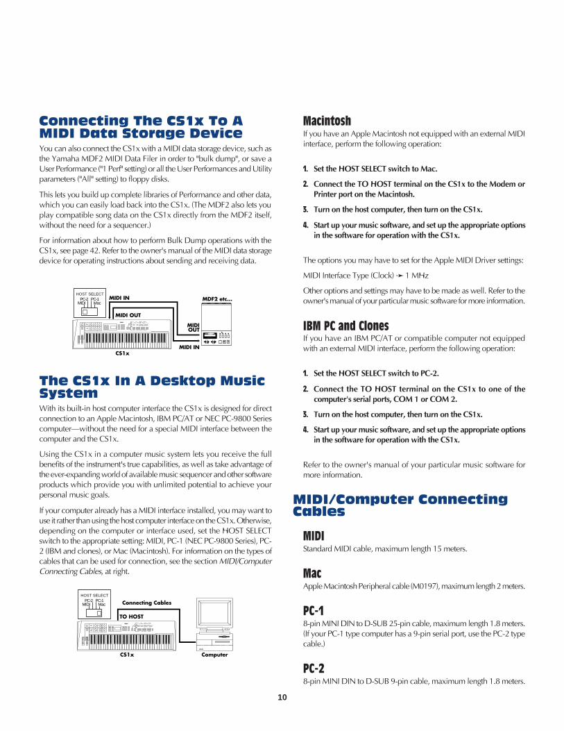
Connecting The CS1x To AMIDI Data Storage DeviceYou can also connect the CS1x with a MIDI data storage device, such asthe Yamaha MDF2 MIDI Data Filer in order to "bulk dump", or save aUser Performance ("1 Perf" setting) or all the User Performances and Utilityparameters ("All" setting) to floppy disks.
This lets you build up complete libraries of Performance and other data,which you can easily load back into the CS1x. (The MDF2 also lets youplay compatible song data on the CS1x directly from the MDF2 itself,without the need for a sequencer.)
For information about how to perform Bulk Dump operations with theCS1x, see page 42. Refer to the owner's manual of the MIDI data storagedevice for operating instructions about sending and receiving data.
MDR SEO JOB UTIL
MIDI
MDF2
MIDI DATA FILTER
CURSOR - FILE DATA +REC PAUSE START/STOP
TEMPO
MDF2 etc...
MIDI IN
MIDIOUT
MIDI OUT
MIDI INHOST SELECT
PC-2 PC-1MIDI Mac
CS1x
The CS1x In A Desktop MusicSystemWith its built-in host computer interface the CS1x is designed for directconnection to an Apple Macintosh, IBM PC/AT or NEC PC-9800 Seriescomputer—without the need for a special MIDI interface between thecomputer and the CS1x.
Using the CS1x in a computer music system lets you receive the fullbenefits of the instrument's true capabilities, as well as take advantage ofthe ever-expanding world of available music sequencer and other softwareproducts which provide you with unlimited potential to achieve yourpersonal music goals.
If your computer already has a MIDI interface installed, you may want touse it rather than using the host computer interface on the CS1x. Otherwise,depending on the computer or interface used, set the HOST SELECTswitch to the appropriate setting: MIDI, PC-1 (NEC PC-9800 Series), PC-2 (IBM and clones), or Mac (Macintosh). For information on the types ofcables that can be used for connection, see the section MIDI/ComputerConnecting Cables, at right.
TO HOST
Connecting CablesHOST SELECT
PC-2 PC-1MIDI Mac
ComputerCS1x
MacintoshIf you have an Apple Macintosh not equipped with an external MIDIinterface, perform the following operation:
1. Set the HOST SELECT switch to Mac.
2. Connect the TO HOST terminal on the CS1x to the Modem orPrinter port on the Macintosh.
3. Turn on the host computer, then turn on the CS1x.
4. Start up your music software, and set up the appropriate optionsin the software for operation with the CS1x.
The options you may have to set for the Apple MIDI Driver settings:
MIDI Interface Type (Clock) 1 MHz
Other options and settings may have to be made as well. Refer to theowner's manual of your particular music software for more information.
IBM PC and ClonesIf you have an IBM PC/AT or compatible computer not equippedwith an external MIDI interface, perform the following operation:
1. Set the HOST SELECT switch to PC-2.
2. Connect the TO HOST terminal on the CS1x to one of thecomputer's serial ports, COM 1 or COM 2.
3. Turn on the host computer, then turn on the CS1x.
4. Start up your music software, and set up the appropriate optionsin the software for operation with the CS1x.
Refer to the owner's manual of your particular music software formore information.
MIDI/Computer ConnectingCables
MIDIStandard MIDI cable, maximum length 15 meters.
MacApple Macintosh Peripheral cable (M0197), maximum length 2 meters.
PC-18-pin MINI DIN to D-SUB 25-pin cable, maximum length 1.8 meters.(If your PC-1 type computer has a 9-pin serial port, use the PC-2 typecable.)
PC-28-pin MINI DIN to D-SUB 9-pin cable, maximum length 1.8 meters.

11
PlayingArpeggiated
ChordsTake a moment and try out the Arpeggiator function, which createsautomatic arpeggios based on the chords you play. First select aPerformance with a fast attack, such as a percussive type sound. (Note:The Arpeggiator function only works in Performance mode.)
1. Press ARPEGGIATOR. An indicator will appear in the lower rightarea of the LCD.
2. Play a chord. The arpeggiated chord will begin playing, based on theArpeggiator Type, Tempo and Subdivide parameter settings.
3. Change the Arpeggiator Type, Tempo and Subdivide parameters usingthe Common Edit 1 menu. (See page 22.)
ARPEGGIO HOLD SHIFT
OCTAVEPART/LAYER/
+
PRESET USER
PROGRAM
+
Arpeggiator HoldThe handy Arpeggiator Hold function lets you play a chord to start theautomatic arpeggio, then take your hand off the keyboard—the arpeggiatedchord will play continuously in a loop. Play another chord and theautomatic arpeggios will change accordingly.
1. Hold SHIFT and press ARPEGGIATOR. The Arpeggiator indicator inthe LCD will start blinking.
2. Play a series of chords.
3. To stop the arpeggiated chords, press ARPEGGIATOR again.
Arpeggiator SplitThe Arpeggiator Split function greatly increases the performance capabilityof the CS1x. When Arpeggiator Split is engaged, any chord you play tothe left of the split point (B2 and below) will produce an arpeggiatedchord, while chords you play to the right of the split point will playnormally.
1. Press ARPEGGIATOR to activate the Arpeggiator function.
2. Set the Edit Parameter Rotary Switch to the Common Edit 1 menu.
3. Hold SHIFT and press the left-most Parameter Value UP/DOWNbutton (Arpeggiator Type parameter).
4. Pressing [UP] will turn on the Arpeggiator Split feature (the letter "S"will display in the LCD); pressing [DOWN] will turn it off.
Switching OnThe Power And
ProducingSound
Once all connections have been properly made, you're ready to switchon the power and start having fun with the CS1x.
1. Turn the volume of the CS1x to its minimum position.
2. Press the POWER switch, located on the rear panel.
3. After a brief greeting message, the CS1x will power up.
4. Gradually turn the VOLUME knob to the right while playing thekeyboard until you achieve a comfortable listening level.
Playing TheDemo Songs
Before you dive in and start exploring the many Performances and otherversatile features of the CS1x, you may want to listen to the preprogrammeddemonstration song.
The Demo provides a dynamic example of just how powerful the CS1xreally is. To play the Demo, perform the following operation:
1. In Performance mode, hold the PERFORMANCE button and pressthe MULTI button.
2. The word "DEMO" will appear in the LCD, and after a brief momentthe Demo song will begin, and continue playing.
3. To stop the Demo, simply press a mode button, such asPERFORMANCE.
PERFORMANCE MULTI
DEMO
STORE UTILITY
When the Demo mode is engaged, you can select a Demo song from thevarious Demo songs using the numeric keypad.

12
How The CS1xGenerates Sound
Oscillators, Filters AndAmplifiersSynthesizers rely on three key electronic components to imitate thesoundwaves of musical instrument voices, as well as create entirely newsounds.
In traditional analog synthesis the source sound pitch is generated by anoscillator, its tone is created by a filter, and its volume is determined byan amplifier.
AMPLIFIERSFILTERSOSCILLATORS
DETERMINESVOLUME
CREATESTONE
GENERATESPITCH
! The oscillator generates sound wave vibrations at controllable speeds,or frequencies, to create pitch. Synthesizer oscillators usually offer arange of frequencies between 20 Hz and 20kHz, which is the rangeof the audio spectrum that most human beings can hear. They alsousually offer various types of sound waveforms, such as sine, sawtooth,and others.
" Musical instrument sounds are made up of the basic tone that weclearly distinguish, plus additional harmonics, or overtones whichexist at each octave above the basic tone, but that we cannot distinctlyhear. The filter provides control over these harmonics. By manipulatingthe filter's cutoff frequency, which decides where to delete—or cutoff—the overtones, and resonance settings, you can thus determinethe tone.
# An amplifier controls the volume of the tone. An envelope generator(EG) determines the tone's volume over time, through attack, decay,sustain and release settings.
AWM2 WaveformsThe CS1x takes the familiar concepts and functions of analog synthesisand combines them with the state of the art in digital synthesis technology.
As such, it has hundreds of AWM2 waveforms, or digital recordings("samples"), of all types of musical instrument and other soundsprogrammed right inside—including everything from a violin bowscraping a string, to a mallet striking a marimba, to a breath blowingacross a flute mouthpiece.
An AWM2 waveform forms the fundamental tone source of a CS1x voice;the rest of the sound is contoured by the oscillator, filter and amplifiersettings. CS1x synthesis gives you enormous realtime and other controlover detailed aspects of all parameter settings.
In order to better understand what's actually happening to the sound asyou turn the Sound Control Knobs or modify other parameters, it is helpfulto first take a look at the key components which make up the physicalnature of sound.
The NatureOf Sound
What is sound? If we could see sounds they would look like waves ripplingthrough the air at a constant speed with high frequencies bunched closetogether and lower frequencies spread far apart.
Our ears are naturally designed to take these physical vibrations—orsound waves—moving through the air around us at high, mid and lowfrequencies, and interpret them as a dog barking across the street, someonepracticing a violin next door, a jet airplane screaming overhead, or rockmusic on the stereo in front of you.
GeneratingElectronic
SoundsThere are three basic elements which make up a sound:
• pitch, or how low or high it is
• tone, or what its overall quality is like
• amplitude, or how loud its volume level is
Before we take a look at how the CS1x generates and manipulates pitch,tone and amplitude, lets first take a look at how these elements applynaturally to acoustic musical instruments.
Acoustic musical instruments are specifically designed and carefully builtto produce precise sound characteristics when played—which is why aviolin always sounds like a violin, a piano always sounds like a piano,and a flute always sounds like a flute.
A musician playing a finely crafted violin will scrape the bow across thestring at a certain intensity to generate violin sound waves at a certainvolume level (amplitude), and produce low or high notes based onfingering positions (pitch). The vibrating strings and resonating wood, aswell as the playing style and technique of the musician, will determinethe overall quality of the violin's sound (tone).

13
CS1x SynthesisThe secret behind the CS1x's exceptional quality sound is its ability to create rich and complex sonic textures in Performances, which are made up ofLayers of up to four AWM2 voices—either sounding simultaneously or mapped to various note and velocity zones across the keyboard.
AMPLIFIERS EFFECTSFILTERS
AWM2 WAVEFORMBANK
PROGRAM NUMBER
CONTROLLER
OSCILLATORS
AWM2 VOICE
LEVEL
ATTACK LEVEL( ATK LEVEL )
RELEASE LEVEL( REL LEVEL )
TIME
RELEASE TIME( REL TIME )
BASIC KEYPLAYED
INITIAL LEVEL( INIT LEVEL )
ATTACK TIME( ATK TIME )
DECAY TIME( DCY TIME )
RELEASE TIME( REL TIME )
CUT OFFFREQUENCY
PITCH VOLUMETIME
LEVEL LEVEL
KEY ON KEY OFF
ATTACK TIME( ATK TIME )
DECAY TIME( DCY TIME )
TIMEATTACK TIME( ATK TIME )
DECAY TIME( DCY TIME )
SUSTAIN LEVEL( SUS LEVEL )
RELEASE TIME( REl TIME )
KEY ON KEY OFF KEY ON KEY OFF
LFO
SUSTAIN LEVEL(SUS LEVEL)
! AWM2 WAVEFORM - The fundamental sourceof the CS1x's sound is the sampled AWM2waveform. There are hundreds preprogrammed inROM which are used by the Performances.Available waveforms are organized in Banks. EachAWM2 waveform has its own Program Number.
" AWM2 VOICE - The AWM2 waveform combineswith the oscillator, filter and amplifier to make upa CS1x voice.
• PEG - The Pitch Envelope Generator controls howthe pitch changes over time.
INIT LEVEL (Initial Level) sets the initial pitch levelwhen a key is played.
ATK TIME (Attack Time) determines the timerequired for a sound to reach its Attack Level aftera note is played.
ATK LEVEL (Attack Level) sets the initially targetedlevel after a note is played.
DCY TIME (Decay Time) determines the timerequired for a sound to reach its basic pitch fromthe Attack Level while the key is held.
REL TIME (Release Time) determines the time ittakes for the basic pitch to reach the Release Levelafter the key has been released.
REL LEVEL (Release Level) sets the final targetedlevel after the key is released.
• FEG - The Filter Envelope Generator controls howthe timbre changes over time.
ATK TIME (Attack Time) determines the timerequired for a sound to reach its maximum cutofffrequency level when a note is played.
DCY TIME (Decay Time) determines the timerequired for a sound to reach its Sustain Level fromthe maximum level while the key is held.
SUS LEVEL (Sustain Level) sets the Sustain Level;the cutoff frequency will be maintained at this levelfor as long as the key is held.
REL TIME (Release Time) determines the time ittakes for the cutoff frequency to reach the levelpreset for each voice after the key has been released.
• AEG - The Amplitude Envelope Generator controlshow the volume changes over time.
ATK TIME (Attack Time) determines the timerequired for a sound to reach its maximum volumelevel when a note is played.
DCY TIME (Decay Time) determines the timerequired for a sound to reach its Sustain Level fromthe maximum volume level while the key is held.
SUS LEVEL (Sustain Level) sets the Sustain Level;the volume will be maintained at this level for aslong as the key is held.
REL TIME (Release Time) determines the time it
takes for a sound to sustain after the key has beenreleased.
# LFO - The Low Frequency Oscillator generates lowfrequency signals which can be used to modulatethe PEG, FEG and AEG.
• PMOD - The LFO can apply Pitch Modulation tothe PEG to create vibrato effects.
• FMOD - The LFO can apply Filter Modulation tothe FEG to create wah-wah types of effects.
• AMOD - The LFO can apply AmplitudeModulation to the AEG to create tremolo effects.
$ CONTROLLER - You can use several types ofcontrollers to manipulate various parameters inrealtime.
• MW - Use the Modulation Wheel to controlPMOD, FMOD, and Filter Cutoff.
• FC - Use the Foot Controller to control FMOD,Filter Cutoff, and Variation Effect.
• Use the Sound Control Knobs to control AEG AttackTime, Release Time, Filter Cutoff, and Resonance.The ASSIGN 1/2 knobs can be specified to controlone of any number of parameters. (See the lists onpages 27 and 29.)

14
CS1x MAINOPERATING
MODESThe CS1x has two main operating modes: Performance mode and MultiPlay mode. The chief distinction between each mode is as follows:
• Performance mode is primarily for realtime performance of Layers. Ithas six menus of Edit parameters.
• Multi Play mode is primarily for multitimbral playback of up to 16Parts when external MIDI devices are connected. It has one menu ofEdit parameters. You can also use the CS1x as a MIDI data inputdevice for an external sequencer.
Utility mode lets you modify System and MIDI parameters which affectboth Performance and Multi Play mode. (For more information aboutUtility mode, see page 40.)
Store mode lets you store your own User Performances and Scenes. (Formore information about Store mode, see page 44.)
PerformanceMode
If you're in a different mode, press the PERFORMANCE button to enterPerformance mode.
In Performance Play mode you can select a Performance from 128 PresetPerformances and 128 User Performances and begin playing.
A Performance is comprised of up to four "Layers", or AWM2 voicessounding at once—either playing simultaneously across the length of thekeyboard, or playing independently according to specified key andvelocity ranges.
There are many Performance parameters which you can edit by offsettingparameter values—i.e., adding to or subtracting from the values whichare preset for each voice. There are basically two ways to go about offsettingthe parameters—by turning the Sound Control Knobs, or using the EditParameter Rotary Switch and Parameter Value UP/DOWN buttons.
Changing any parameter will automatically engage Performance Editmode. (You can easily switch back Performance Play mode by pressingthe PERFORMANCE button or PROGRAM [–]/[+] button.)
ATTACKAMP EG
RELEASE ASSIGN 1/DATAVOLUME
CUTOFFFILTER
RESONANCE ASSIGN 2
2
MW/FC
1
SCENE
Turning the Sound Control Knobs will give you direct access to the AMPEG and FILTER parameters, thus providing analog-style realtime controlover key characteristics of the sound. You can also save up to two"snapshots" of knob positions in Scenes, which can be instantly recalledat the touch of a SCENE button.
Another way to edit a Performance is with the Edit Parameter RotarySwitch and Parameter Value UP/DOWN buttons. These give you controlover both "Common" parameters which affect all Layer voices equally,and "Layer" parameters which affect individual Layers, or AWM2 voices.
PERFORMANCE MULTI
DEMO
STORE UTILITY
TYPE
BANK
P BENDRANGE
NOTESFT
ATKTIME
ATKTIME
MASTERTUNE
TEMPOARPEGGIATOR PERFORM
LEVELEFECT
PROGRAM
SYSTEM MIDI ASSIGN
PMOD
DETUNE
DCYTIME
DCYTIME
KBDTRANS
SUBDIVIDE
VOLUME
FMOD
REVTYPE
CUTOFFFC PORTA
VEL ASSIGN2
LFO
PEG
CHOTYPE
VARIEF
VARITYPE
SWITCH
VARIPARAM
TIME
VARIDATA
MWFMOD
LIMITLOW
TUNE
AEG
FEG
NOTE
SUSLEVEL
SUSLEVEL
VELCURVE
PAN
CUTOFF
LIMITHIGH
RELTIME
RELTIME
VELFIX
REVSEND
LIMITLOW
AMOD
INITLEVEL
TRANSCH
CHOSEND
LIMITHIGH
PMOD
ATKTIME
EFFECT
RCVCH
VARISEND
OFFSET
FMOD
ATKLEVEL
DEVICENO
CUTOFFFILTER
DEPTH
WAVE
DCYTIME
LOCAL
REZ
PARAM
SPEED
RELTIME
BULKDUMP
PERFORMNAME
POLY/MONO
ASSIGN1PARAM
DATA
PHASEINIT
RELLEVEL
CTRLNO
COMMON
LAYER
UTILITY
Edit Parameter Rotary Switch
Parameter Value UP/DOWN Buttons
In Performance mode there are six Edit menus of Common and Layerparameters which can be accessed via the Edit Parameter Rotary Switchand modified with the Parameter Value UP/DOWN buttons.
Try changing the voice assignments to each Layer. This is a quick andeffective way to create an entirely new Performance, which you caneasily store as a User Performance.
Assigning voices to the Layers is simple. Choose the Layer (1~4) with thePART/LAYER [–]/[+] buttons, and select from a variety of AWM2instrument voices and drum voices using the Bank and ProgramParameters (Layer Edit 4, sixth row from the top).

15
next to the Performance number, to indicate
that the edited sound has not been stored.
• Offset AMP EG and FILTER parameters tochange the shape and tone of the sound asyou play by turning the Sound Control Knobs.
• Replace the Layer voice assignment, or editother Performance Common and Layerparameters, with the Edit Parameter RotarySwitch and Parameter Value UP/DOWNbuttons.
• Press ARPEGGIATOR to turn it ON, and playa chord to start the arpeggiated chords. SelectArpeggiator Type, Tempo and otherparameters from the Common Edit 1 menu.
STOREStore mode lets you store Scenes as well as
User Performances for later recall.
• Store your favorite Scenes, or "snapshots" ofSound Control Knob positions, in the currentlyselected Performance. (See page 44.)
• Store your own Performances in the 128 UserPerformance memories. (See page 44.)
PERFORMANCEPLAYPerformance Play mode lets you select a
Preset or User Performance for realtime play.
• Press the PERFORMANCE button to enterPerformance mode (if you're in a differentmode).
• Press either the PRESET or USER button toselect the Preset or User Performance bank.
• Choose a Performance with the PROGRAM[–]/[+] buttons.
• Use realtime control features as you play,including the Pitch Bend and ModulationWheels.
• Transpose the octave up or down by holdingSHIFT and pressing PART/LAYER [–]/[+]. Youcan transpose the pitch up ([+]) or down ([–])by as many as three octaves, depending onthe Performance. (The transpose value willalso be reflected in the Utility mode'sKeyboard Transpose function. NOTE:Maximum is ±3 octaves; however, when youraise or lower the pitch in semitones, forexample, three octaves cannot be achievedusing the SHIFT button.)
PERFORMANCE EDITMaking any adjustment—either intentionally
or inadvertently—to any parameter will
engage Performance Edit mode. When
exiting from the Performance Edit mode (by
pressing PERFORMANCE or PROGRAM
[–]/[+]), an "E" will be displayed in the LCD
BasicOperations InPerformanceMode
BasicOperations InPerformanceMode
15

16
Performance Structure
007006
005004
003002
001
VOICELayer 3
VOICE
001Performance Layer 4
Layer 2
VOICE
Preset Bank User Bank128 Performance
007006
005004
003002
001
128 Performance
Layer 1
VOICE
PERFORMANCE MULTI
DEMO
STORE UTILITY
TYPE
BANK
P BENDRANGE
NOTESFT
ATKTIME
ATKTIME
MASTERTUNE
TEMPOARPEGGIATOR PERFORM
LEVELEFECT
PROGRAM
SYSTEM MIDI ASSIGN
PMOD
DETUNE
DCYTIME
DCYTIME
KBDTRANS
SUBDIVIDE
VOLUME
FMOD
REVTYPE
CUTOFFFC PORTA
VEL ASSIGN2
LFO
PEG
CHOTYPE
VARIEF
VARITYPE
SWITCH
VARIPARAM
TIME
VARIDATA
MWFMOD
LIMITLOW
TUNE
AEG
FEG
NOTE
SUSLEVEL
SUSLEVEL
VELCURVE
PAN
CUTOFF
LIMITHIGH
RELTIME
RELTIME
VELFIX
REVSEND
LIMITLOW
AMOD
INITLEVEL
TRANSCH
CHOSEND
LIMITHIGH
PMOD
ATKTIME
EFFECT
RCVCH
VARISEND
OFFSET
FMOD
ATKLEVEL
DEVICENO
CUTOFFFILTER
DEPTH
WAVE
DCYTIME
LOCAL
REZ
PARAM
SPEED
RELTIME
BULKDUMP
PERFORMNAME
POLY/MONO
ASSIGN1PARAM
DATA
PHASEINIT
RELLEVEL
CTRLNO
COMMON
LAYER
UTILITY
LAYER EDIT
COMMON EDIT
REAL TIME EDIT with THE SOUND CONTROL KNOBS
STORE IN USER BANK
SAVE AS SCENE 1 or 2
ATTACKAMP EG
RELEASE ASSIGN 1/DATA
CUTOFFFILTER
RESONANCE ASSIGN 2
2
MW/FC
1
SCENE
! PERFORMANCE BANKS - The CS1x comes preprogrammed with128 Preset Performances and 128 User Performances. You can editthe Layers of the currently selected Performance and store it in a UserPerformance.
" LAYERS - A Performance consists of up to four Layers—each Layercan be assigned its own AWM2 voice. There are many Layer andCommon Performance parameters which can be edited.
# AMP EG/FILTER - Turning the Sound Control Knobs will affect allLayers equally by offsetting AMP EG parameters to control the shapeof the volume of the sound over time, and FILTER parameters to controlthe quality of the tone. In Edit mode you can assign which parametersthe ASSIGN 1 and ASSIGN 2 knobs will control.
$ COMMON EDIT 1~2 - These are "Common" parameters which affectall Layers in the Performance equally.
% LAYER EDIT 1~4 - These are "Layer" parameters which let you modifythe characteristics of each individual Layer. Select the Layer you wantto edit using the PART/LAYER [–]/[+] buttons.
Storing User PerformancesStoring your own User Performance is a quick and simple operation.
1. To store the current Performance, press the STORE button once.
2. Choose a User Performance number (1~128) using the numerickeypad.
3. Press ENTER.
A "Sure?" prompt will appear in the LCD. Press YES to store thePerformance. Press NO to abort the operation.
ScenesThere are two "Scene" memories dedicated to each Performance. Scenesare simply "snapshots" of specific positions of the Sound Control Knobs—instantly accessible via the SCENE buttons.
You can select one of the Scenes by pressing the SCENE 1 or SCENE2 button. Or you can hold one SCENE button and press the other,then use the Modulation Wheel or Foot Controller for realtimecontinuous parameter changes between one Scene and the other.The default controller is Modulation Wheel. The minimum positionof the controller is Scene1, and the maximum position is Scene 2.
Storing ScenesYou can easily store your own Scenes in a Performance—eithertemporarily or permanently.
To store a Scene temporarily in the currently selected Performance, holda SCENE button and press STORE.
This will store the Scene in the edit buffer as long as the current Performanceis selected, so that the original Scenes are protected. If you select anotherPerformance, any new Scenes will be lost.
To store a Scene permanently in a Performance, simply perform the Storeoperation for User Performances. (See Storing User Performances, above.)
17
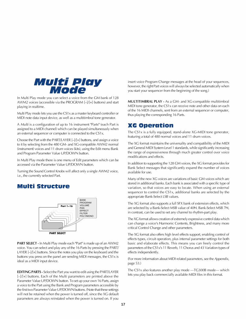
Multi PlayMode
In Multi Play mode you can select a voice from the GM bank of 128AWM2 voices (accessible via the PROGRAM [–]/[+] buttons) and startplaying in realtime.
Multi Play mode lets you use the CS1x as a master keyboard controller orMIDI note data input device, as well as a multitimbral tone generator.
A Multi is a configuration of up to 16 instrument "Parts" (each Part isassigned to a MIDI channel) which can be played simultaneously whenan external sequencer or computer is connected to the CS1x.
Choose the Part with the PART/LAYER [–]/[+] buttons, and assign a voiceto it by selecting from the 480 GM- and XG-compatible AWM2 normal(instrument) voices and 11 drum voices (kits), using the Edit menu Bankand Program Parameter Value UP/DOWN button.
In Multi Play mode there is one menu of Edit parameters which can beaccessed via the Parameter Value UP/DOWN button.
Turning the Sound Control Knobs will affect only a single AWM2 voice,i.e., the currently selected Part.
Multi Structure
76
54
32
1
Part 1~16
BANKPROGRAMVOLUMEPANEFFECTFILTERPOLY/MONO
PART SELECT
PART SELECT - In Multi Play mode each "Part" is made up of an AWM2voice. You can select and play any of the 16 Parts by pressing the PART/LAYER [–]/[+] buttons. Since the notes you play on the keyboard and thebuttons you press on the panel are sending MIDI messages, the CS1x isideal as a MIDI input device.
EDITING PARTS - Select the Part you want to edit using the PART/LAYER[–]/[+] buttons. Each of the Multi parameters are printed above theParameter Value UP/DOWN button. To set up your own 16 Parts, assigna voice to the Part using the Bank and Program parameters accessible bythe first two Parameter Value UP/DOWN buttons. (Note that these settingswill not be retained when the power is turned off, since the XG defaultparameters are always reinstated when the power is turned on. If you
insert voice Program Change messages at the head of your sequences,however, the right Part voices will always be selected automatically whenyou start your sequencer from the beginning of the song.)
MULTITIMBRAL PLAY - As a GM- and XG-compatible multitimbralMIDI tone generator, the CS1x can receive note and other data on eachof the 16 MIDI channels, sent from an external sequencer or computer,thus playing the corresponding 16 Parts.
XG OperationThe CS1x is a fully equipped, stand-alone XG-MIDI tone generator,featuring a total of 480 normal voices and 11 drum voices.
The XG format maintains the universality and compatibility of the MIDIand General MIDI System Level 1 standards, while significantly increasingthe range of expressiveness through much greater control over voicemodifications and effects.
In addition to supporting the 128 GM voices, the XG format provides forBank Select messages that significantly expand the number of voicesavailable for use.
Many of the new XG voices are variations of basic GM voices which arestored in additional banks. Each bank is associated with a specific type ofvariation, so that voices are easy to locate. When using an externalsequencer to control the CS1x, additional banks are selected by theappropriate Bank-Select LSB values.
The XG format also supports a full SFX bank of extension effects, whichare selected by a Bank-Select MSB value of 40H. Bank-Select MSB 7H,in contrast, can be used to set any channel to rhythm-part play.
The XG format allows creation of extremely expressive control data whichcan change a voice's Harmonic Contents, Brightness, and many morecritical Control Change and other parameters.
The XG format also offers high level effects support, enabling control ofeffects types, circuit operation, plus internal parameter settings for bothbasic and elaborate effects. This means you can freely control theparameters of the CS1x's 11 Reverb, 11 Chorus and 43 Variation types ofeffects independently.
(For more information about MIDI related parameters, see the Appendix,page 53.)
The CS1x also features another play mode —TG300B mode— whichlets you play back commercially available MIDI files in this format.

18


20
Selecting a Performance1. Use the numeric keypad (0 ~ 9) to select the Performance
number you want.
For more information about each Performance, see thePerformance List in the "Data List" book.
2. Press the ENTER button to confirm the Performance number(1~128). The Performance name and number you haveselected will display in the LCD. The Category name will beshown next to the Performance name.
Press the PROGRAM [+] button to select the next Performancenumber. Press the PROGRAM [-] button to select the previousPerformance number.
ARPEGGIO HOLD SHIFT
OCTAVEPART/LAYER/
+
PRESET USER
PROGRAM
+
VWX
7
YZ'
8
&*
9MNO
4
PQR
5
STU
6DEF
1
GHI
2
JKL
NO/QUICK PC
YES
3ABC
0
SPACE
ENTER
Performance Name
Category
Performance Number
NOTE
VWX
7
YZ'
8
&*
9MNO
4
PQR
5
STU
6DEF
1
GHI
2
JKL
NO/QUICK PC
YES
3ABC
0
SPACE
ENTER
Entering Performance ModePress the PERFORMANCE button. A [] mark will appear in theLCD below the word "PERFORMANCE".
Performance Play Mode
Selecting a BankThere are 2 banks, a Preset bank and a User bank. Each bankcontains 128 Performances.
Press the PRESET button or the USER button to select the bank you want.A [] mark will appear in the LCD above the word "PRESET" or "USER".
RPEGGIO HOLD SHIFT
OCTAVEPART/LAYER/
+
PRESET USER
PROGRAM
+
RPEGGIO HOLD SHIFT
OCTAVEPART/LAYER/
+
PRESET USER
PROGRAM
+
Preset Bank User Bank
007006
005004
003002
001
128 Performance
007006
005004
003002
001
128 Performance
PERFORMANCE STOREMULTI
PRESET USER ARPEGGIATOR
UTILITY
ERFORMANCE MULTI
DEMO
STORE UTILITY
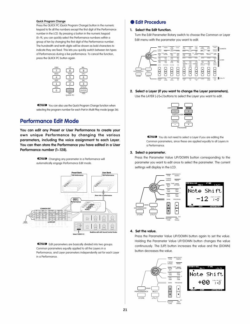
In Performance mode you can choose from 128 Preset and 128 User Performances. A Performance consists of a maximum of four layered sounds (voices). The Performance Edit function lets you easily edit each Layer within a Performance. The various parameters give you the flexibility to create a vast variety of sounds.
Following is a description of each function in the various modes.
21
Quick Program ChangePress the QUICK PC (Quick Program Change) button in the numerickeypad to fix all the numbers except the first digit of the Performancenumber in the LCD. By pressing a button in the numeric keypad(0~9), you can quickly select the Performance numbers within agroup of ten by changing the first digit of the Performance number.The hundredth and tenth digits will be shown as bold characters toindicate they are fixed. This lets you quickly switch between ten typesof Performances during a live performance. To cancel the function,press the QUICK PC button again.
You can also use the Quick Program Change function whenselecting the program number for each Part in Multi Play mode (page 36).
Performance Edit ModeYou can edit any Preset or User Performance to create yourown unique Performance by changing the variousparameters, including the voice assignment to each Layer.You can then store the Performance you have edited in a UserPerformance number (1~128).
Changing any parameter in a Performance willautomatically engage Performance Edit mode.
Edit parameters are basically divided into two groups:Common parameters equally applied to all the Layers in aPerformance, and Layer parameters independently set for each Layerin a Performance.
NOTE
Preset Bank User Bank
007006
005004
003002
001
128 Performance
007006
005004
003002
001
128 Performance
001Performance Layer 4
Layer 3Layer 2
Layer 1
VOICEVOICE
VOICEVOICE
PERFORMANCE MULTI
DEMO
STORE UTILITY
TYPE
BANK
P BENDRANGE
NOTESFT
ATKTIME
ATKTIME
MASTERTUNE
TEMPOARPEGGIATOR PERFORM
LEVELEFECT
PROGRAM
SYSTEM MIDI ASSIGN
PMOD
DETUNE
DCYTIME
DCYTIME
KBDTRANS
SUBDIVIDE
VOLUME
FMOD
REVTYPE
CUTOFFFC PORTA
VEL ASSIGN2
LFO
PEG
CHOTYPE
VARIEF
VARITYPE
SWITCH
VARIPARAM
TIME
VARIDATA
MWFMOD
LIMITLOW
TUNE
AEG
FEG
NOTE
SUSLEVEL
SUSLEVEL
VELCURVE
PAN
CUTOFF
LIMITHIGH
RELTIME
RELTIME
VELFIX
REVSEND
LIMITLOW
AMOD
INITLEVEL
TRANSCH
CHOSEND
LIMITHIGH
PMOD
ATKTIME
EFFECT
RCVCH
VARISEND
OFFSET
FMOD
ATKLEVEL
DEVICENO
CUTOFFFILTER
DEPTH
WAVE
DCYTIME
LOCAL
REZ
PARAM
SPEED
RELTIME
BULKDUMP
PERFORMNAME
POLY/MONO
ASSIGN1PARAM
DATA
PHASEINIT
RELLEVEL
CTRLNO
COMMON
LAYER
UTILITY
LAYER EDIT
COMMON EDIT
Realtime edit with Sound Control Knobs
Store into a Performance
Select SCENE 1/2
ATTACKAMP EG
RELEASE ASSIGN 1/DATA
CUTOFFFILTER
RESONANCE ASSIGN 2
2
MW/FC
1
SCENE
NOTE
NOTE
VWX
7
YZ'
8
&*
9MNO
4
PQR
5
STU
6DEF
1
GHI
2
JKL
NO/QUICK PC
YES
3ABC
0
SPACE
ENTER
Edit Procedure1. Select the Edit function.
Turn the Edit Parameter Rotary switch to choose the Common or LayerEdit menu with the parameter you want to edit.
2. Select a Layer (if you want to change the Layer parameters).Use the LAYER [-]/[+] buttons to select the Layer you want to edit.
You do not need to select a Layer if you are editing theCommon parameters, since these are applied equally to all Layers ina Performance.
3. Select a parameter.Press the Parameter Value UP/DOWN button corresponding to theparameter you want to edit once to select the parameter. The currentsettings will display in the LCD.
4. Set the value.Press the Parameter Value UP/DOWN button again to set the value.Holding the Parameter Value UP/DOWN button changes the valuecontinuously. The [UP] button increases the value and the [DOWN]button decreases the value.
PERFORMANCE MULTI
DEMO
STORE UTILITY
TYPE
BANK
P BENDRANGE
NOTESFT
ATKTIME
ATKTIME
MASTERTUNE
TEMPOARPEGGIATOR PERFORM
LEVELEFECT
PROGRAM
SYSTEM MIDI
PMOD
DETUNE
DCYTIME
DCYTIME
KBDTRANS
SUBDIVIDE
VOLUME
FMOD
REVTYPE
CUTOFFFC
VEL
LFO
PEG
CHOTYPE
VARIEF
VARITYPE
S
PMW
FMOD
LIMITLOW
TUNE
AEG
FEG
NOTE
DCYLEVEL
DCYLEVEL
VELCURVE
PAN
CUTOFF
LIMITHIGH
RELTIME
RELTIME
VELFIX
REVSEND
LIMITLOW
AMOD
INITLEVEL
TRANSCH
CHOSEND
LIMITHIGH
PMOD
ATKTIME
EFFECT
RCVCH
VARISEND
OFFSET
FMOD
ATKLEVEL
DEVICENO
C
D
PERFORMANCE MULTI
DEMO
STORE UTILITY
TYPE
BANK
P BENDRANGE
NOTESFT
ATKTIME
ATKTIME
MASTERTUNE
TEMPOARPEGGIATOR PERFORM
LEVELEFECT
PROGRAM
SYSTEM MIDI
PMOD
DETUNE
DCYTIME
DCYTIME
KBDTRANS
SUBDIVIDE
VOLUME
FMOD
REVTYPE
CUTOFFFC
VEL
LFO
PEG
CHOTYPE
VARIEF
VARITYPE
SW
VAPAR
MWFMOD
LIMITLOW
TUNE
AEG
FEG
NOTE
DCYLEVEL
DCYLEVEL
VELCURVE
PAN
CUTOFF
LIMITHIGH
RELTIME
RELTIME
VELFIX
REVSEND
LIMITLOW
AMOD
INITLEVEL
TRANSCH
CHOSEND
LIMITHIGH
PMOD
ATKTIME
EFFECT
RCVCH
VARISEND
OFFSET
FMOD
ATKLEVEL
DEVICENO
CU
DE
W
DT
LO
NOTE
ARPEGGIO HOLD SHIFT
OCTAVEPART/LAYER/
+
PRESET USER
PROGRAM
+
PERFORMANCE MULTI
DEMO
STORE UTILITY
TYPE
BANK
P BENDRANGE
NOTESFT
ATKTIME
ATKTIME
MASTERTUNE
TEMPOARPEGGIATOR PERFORM
LEVELEFECT
PROGRAM
SYSTEM MIDI ASSIGN
PMOD
DETUNE
DCYTIME
DCYTIME
KBDTRANS
SUBDIVIDE
VOLUME
FMOD
REVTYPE
CUTOFFFC PORTA
VEL ASSIGN2
LFO
PEG
CHOTYPE
VARIEF
VARITYPE
SWITCH
VARIPARAM
TIME
VARIDATA
MWFMOD
LIMITLOW
TUNE
AEG
FEG
NOTE
SUSLEVEL
SUSLEVEL
VELCURVE
PAN
CUTOFF
LIMITHIGH
RELTIME
RELTIME
VELFIX
REVSEND
LIMITLOW
AMOD
INITLEVEL
TRANSCH
CHOSEND
LIMITHIGH
PMOD
ATKTIME
EFFECT
RCVCH
VARISEND
OFFSET
FMOD
ATKLEVEL
DEVICENO
CUTOFFFILTER
DEPTH
WAVE
DCYTIME
LOCAL
REZ
PARAM
SPEED
RELTIME
BULKDUMP
PERFORMNAME
POLY/MONO
ASSIGN1PARAM
DATA
PHASEINIT
RELLEVEL
CTRLNO
COMMON
LAYER
UTILITY

22
To exit Performance Edit mode, press the PERFORMANCEbutton again or the PROGRAM [-]/[+] button. You can enter Multi Playmode directly from Performance mode by pressing the MULTI button.
Edit MarkOnce you have edited a Performance in any way, an edit mark (areversed type letter "E") will appear to the left of the Performancenumber. This mark indicates you have edited, but not stored thePerformance.
The edit mark will also appear simply by making a slightposition change to a Sound Control Knob (see page 6).
Description of Each Function
Common Edit 1 (applied to all Layers)This row provides functions and parameters which are commonto all Layers in a Performance, such as the Arpeggiator, and thePerformance Level, Effect and Name.
ARPEGGIATORThe Arpeggiator automatically creates arpeggiated chordsbased on the chords/melodies you play on the keyboard. Thereare three Arpeggiator parameters: TYPE, TEMPO and SUBDIVIDE.
TYPE TEMPO
SUBDIVIDE
PERFORMANCE MULTI
DEMO
STORE UTILITY
TYPE
BANK
P BENDRANGE
NOTESFT
ATKTIME
ATKTIME
TEMPOARPEGGIATOR PERFORM
LEVELEFECT
PROGRAM
SYSTEM MIDI ASSIGN
PMOD
DETUNE
DCYTIME
DCYTIME
SUBDIVIDE
VOLUME
FMOD
REVTYPE
CUTOFFFC PORTA
VEL ASSIGN2
LFO
PEG
CHOTYPE
VARIEF
VARITYPE
SWITCH
VARIPARAM
TIME
VARIDATA
MWFMOD
LIMITLOW
TUNE
AEG
FEG
NOTE
DCYLEVEL
DCYLEVEL
PAN
CUTOFF
LIMITHIGH
RELTIME
RELTIME
REVSEND
LIMITLOW
AMOD
INITLEVEL
CHOSEND
LIMITHIGH
PMOD
ATKTIME
EFFECTVARISEND
OFFSET
FMOD
ATKLEVEL
CUTOFFFILTER
DEPTH
WAVE
DCYTIME
REZ
PARAM
SPEED
RELTIME
PERFORMNAME
POLY/MONO
ASSIGN1PARAM
DATA
PHASEINIT
RELLEVEL
COMMON
LAYER
NOTE
Indicates you have edited, but not stored the Performance.
NOTEYou can also use the numeric keypad (0~9) or the DataEntry knob to change the value.
To change the value for all four Layers at one time, holdSHIFT and press the Parameter Value UP/DOWN button. When youpress SHIFT in Performance Edit mode, a letter "A" (All) will appear inthe LCD below the word "LAYER".
Each voice is preset with optimum settings for the parameters,and the value you set for any parameter will offset (add or subtract) thepreset value. If the value of a parameter exceeds the maximum orminimum limit available, the highest or lowest value will be used.
The actual value is the sum of the value displayed in theLCD and the value set by the Sound Control Knob.
The original voice can be restored and heard by returningto Performance Play mode and moving the Sound Control Knob to thecenter position.
You can replace the voices currently assigned to each Layerwith new voices or assign a voice to an empty Layer (up to fourvoices/Layers for a Performance).
5. Set the other parameters.As you continue pressing the other Parameter Value UP/DOWNbuttons, the other parameters will appear in the display. Set the otherparameters to your preference.
6. Store the Performance.When you have finished editing, store the Performance as a UserPerformance. For details about how to store a Performance, see page 44.
The edited contents will be retained in memory even if youturn the power off during an edit. The Performance you were editingwill still be selected the next time you turn the power on, and you willbe able to pick up from where you left off and continue editing thePerformance.
While editing a Performance, if you select anotherPerformance or press the PERFORMANCE button again to exitPerformance Edit mode before you have first stored the data as aUser Performance, your edited data will be lost. For details aboutstoring a User Performance, see page 44.
NOTE
NOTE
NOTE
NOTE
NOTE
PERFORMANCE MULTI
DEMO
STORE UTILITY
TYPE
BANK
P BENDRANGE
NOTESFT
ATKTIME
ATKTIME
MASTERTUNE
TEMPOARPEGGIATOR
PROGRAM
SYSTEM
PMOD
DETUNE
DCYTIME
DCYTIME
KBDTRANS
D
VO
F
LTUNE
AEG
FEGL
L
C
ARPEGGIO HOLD SHIFT
OCTAVEPART/LAYER/
+
PRESET USER
PROGRAM
+
NOTE
NOTE

23
To start the Arpeggiator, press the ARPEGGIATOR button to turn iton. A [ ] mark wil l appear in the LCD above the word"ARPEGGIATOR".
To turn the Arpeggiator off, press the ARPEGGIATOR buttonagain.
TYPE: Sets the type of arpeggio. You can choose from 30 types.For details about each type, see the Arpeggiator Type List in the"Data List" book.
Arpeggiator HoldThe Arpeggiator Hold function lets you play a chord to start theautomatic arpeggio, then take your hand off the keyboard; thearpeggiated chord will play continuously in a loop. Play anotherchord and the automatic arpeggios will change accordingly.
To activate the Arpeggiator Hold function, perform the following:
1. Hold SHIFT and press ARPEGGIATOR. The Arpeggiator indicator inthe LCD will start blinking.
2.Play a series of chords.
3.To stop the arpeggiated chords, press ARPEGGIATOR again.
Arpeggiator SplitIf you hold SHIFT and press the Parameter Value [UP] button whenthe TYPE parameter is displayed in the LCD, the Arpeggiator Splitfunction will be enabled, and a reversed type letter "S" will appearto the right of the Arpeggiator type.
The Split function splits the keyboard from C3 (indicated above thekeyboard with []) and will allow you to play the arpeggiated chordson the lower half (below C3) of the keyboard, and play a melody line onthe upper half (C3 and above).
To cancel the Split function, hold SHIFT and press the ParameterValue [DOWN] button.
TEMPO: Sets the tempo of the Arpeggiator. The range is MIDI, 40~ 240.
Settings:TEMPO: MIDI, 40 ~ 240 (beats per minute)
If you want to synchronize the tempo of the Arpeggiatorwith that of an external MIDI device, set the TEMPO parameter to MIDI.
SUBDIVIDE: Determines the basic note settings (how fine thetempo is divided) of the Arpeggiator.
The Arpeggiator data cannot be output as the MIDI messages.NOTE
Settings:SUBDIVIDE: 3/8= , 1/4= , 3/16= , 1/6= , 1/8= , 3/32= , 1/12= , 1/16= , 1/24= , 1/32=
NOTE
NOTE
PERFORM LEVELThis sets the volume of each Performance.
Settings:PERFORM LEVEL (Performance Level): 0~127
EFFECTThere are five effect parameters: REV TYPE (Reverb Type), CHOTYPE (Chorus Type), VARI TYPE (Variation Type), VARI PARAM(Variation Parameter) and VARI DATA (Variation Data).For more basic information on each effect, see page 47.
REV TYPE (Reverb Type): Sets the Reverb type. You can choosefrom 11 types. For more information about each Reverb type, seeEffect Type List on page 49.
CHO TYPE (Chorus Type): Sets the Chorus type. You can choosefrom 11 types. For more information about each Chorus type, seeEffect Type List on page 49.
VARI TYPE (Variation Type): Sets the Variation effect type. There are43 types to choose from. For more information about each Variationeffect type, see Effect Type List on page 49.
VARI PARAM (Variation Parameter): Selects the Variation effectparameters. Parameters will differ depending on the Variationeffect type selected in VARI TYPE.
Reverb Type Chorus Type
Variation ParameterVariation Type
Variation DataThe letter "P" (Parameter) or "d" (Data) displays to distinguish between the Variation Parameter and Variation Data screens.

24
PERFORM NAME (Performance Name)This lets you select the Category and name the User Performancesusing up to eight letters, numbers, symbols and characters.
1. Use the Parameter Value UP/DOWN button to move thecursor to the position at which you want to enter acharacter.
2. Move the cursor left-most if necessary (the word"Category" will appear instead of the Performancename) and use the numeric keypad (0~9) to select theCategory.
3. Move the cursor one position to the right (the currentcursor position will start blinking) and use the numerickeypad (0~9) to select the first letter, then right oneposition more and select the second letter, etc., until youcomplete your Performance name.
Settings:A B C D E F G H I J K L M N O P Q R S T U V W X Y Z ' a b c d e f gh i j k l m n o p q r s t u v w x y z 0 1 2 3 4 5 6 7 8 9 - / . , * & _(space)
PERFORMANCE MULTI
DEMO
STORE UTILITY
TYPE
BANK
P BENDRANGE
NOTESFT
ATKTIME
ATKTIME
MASTERTUNE
TEMPOARPEGGIATOR PERFORM
LEVELEFECT
PROGRAM
SYSTEM MIDI ASSIGN
PMOD
DETUNE
DCYTIME
DCYTIME
KBDTRANS
SUBDIVIDE
VOLUME
FMOD
REVTYPE
CUTOFFFC PORTA
VEL ASSIGN2
LFO
PEG
CHOTYPE
VARIEF
VARITYPE
SWITCH
VARIPARAM
TIME
VARIDATA
MWFMOD
LIMITLOW
TUNE
AEG
FEG
NOTE
SUSLEVEL
SUSLEVEL
VELCURVE
PAN
CUTOFF
LIMITHIGH
RELTIME
RELTIME
VELFIX
REVSEND
LIMITLOW
AMOD
INITLEVEL
TRANSCH
CHOSEND
LIMITHIGH
PMOD
ATKTIME
EFFECT
RCVCH
VARISEND
OFFSET
FMOD
ATKLEVEL
DEVICENO
CUTOFFFILTER
DEPTH
WAVE
DCYTIME
LOCAL
REZ
PARAM
SPEED
RELTIME
BULKDUMP
PERFORMNAME
POLY/MONO
ASSIGN1PARAM
DATA
PHASEINIT
RELLEVEL
CTRLNO
COMMON
LAYER
UTILITY
# LCD Category Name0 -- Not specified1 Pf Piano2 Cp Chromatic Percussion3 Or Organ4 Gt Guitar5 Ba Bass6 St Strings/Orchestral7 En Ensemble8 Br Brass9 Rd Reed10 Pi Pipe11 Ld Synth Lead12 Pd Synth Pad13 Fx Synth SFX14 Et Ethnic15 Pc Percussive16 Se Sound Effect17 Dr Drums18 Sc Synth Comping19 Vo Vocal20 Co Combination21 Wv Material Wave22 Sq Sequence
If you select EFFECT OFF in the Variation Type menu, thelayers which have the VARI SEND function set to ON will not sound.When you don't want to use the Variation Effect on the layers, set VARITYPE to Thru.
Variation effect works as an Insertion effect in Performancemode. For more information, see page 47.
For more information about each Variation effect parameter, seeEffect Parameter List on page 49.
VARI DATA (Variation Data): Sets the data (value) of theVariation effect parameter selected in VARI PARAM. For moreinformation about each Variation effect data, see the Effect DataAssign Table on page 51.
When VARI TYPE is turned off, VARI PARAM and VARI DATAwill be disabled.
The effect depth and other parameters can be controlledusing the ASSIGN 1 Sound Control Knob or a Foot Controller. Fordetails, see page 26.
For more information, see page 47.NOTE
NOTE
NOTE
NOTE
NOTE

25
Common Edit 2 (applied to all Layers)This row provides functions and parameters which are commonto all Layers in a Performance (except for "Portament"), includingthe settings for realtime controllers such as the Pitch Wheel,Modulation Wheel and Foot Controller.
P BEND RANGE (Pitch Bend Range)This sets the Pitch Bend range in semitones. The pitch can bebent up or down within the range set here by moving the PitchWheel.
Settings:-24 ~ +24 semitones
PERFORMANCE MULTI
DEMO
STORE UTILITY
BANK
NOTESFT
ATKTIME
ATKTIME
PROGRAM
DETUNE
DCYTIME
DCYTIME
VOLUME
VEL ASSIGN2
LFO
PEG
LIMITLOW
TUNE
AEG
FEG
NOTE
DCYLEVEL
DCYLEVEL
PAN
LIMITHIGH
RELTIME
RELTIME
REVSEND
LIMITLOW
AMOD
INITLEVEL
CHOSEND
LIMITHIGH
PMOD
ATKTIME
EFFECTVARISEND
OFFSET
FMOD
ATKLEVEL
CUTOFFFILTER
DEPTH
WAVE
DCYTIME
REZ
PARAM
SPEED
RELTIME
POLY/MONO
DATA
PHASEINIT
RELLEVEL
LAYER
TYPE
P BENDRANGE
TEMPOARPEGGIATOR PERFORM
LEVELEFECT
PMOD
SUBDIVIDE
FMOD
REVTYPE
CUTOFFFC PORTA
CHOTYPE
VARIEF
VARITYPE
SWITCH
VARIPARAM
TIME
VARIDATA
MWFMOD CUTOFF
PERFORMNAME
ASSIGN1PARAM
COMMON
MW (Modulation Wheel)This sets the control parameters of the Modulation Wheel. Thereare three parameters: PMOD (Pitch Modulation), FMOD (FilterModulation) and CUTOFF (Cutoff). The parameters set here canbe controlled with the Modulation Wheel to add vibrato ortremolo effects to the sound.
PMOD (Pitch Modulation): Sets the pitch modulation depthcreated by the LFO (Low Frequency Oscillator). The value set herewill determine the range of the pitch modulation by theModulation Wheel. Moving the Modulation Wheel up willincrease the depth of the pitch modulation, while moving itdown will decrease the depth.
FMOD (Filter Modulation): Sets the filter modulation depthcreated by the LFO (Low Frequency Oscillator). The value set herewill determine the range of the fi lter modulation by theModulation Wheel. Moving the Modulation Wheel up willincrease the depth of the filter modulation, while moving it downwill decrease the depth.
CUTOFF (Cutoff): Sets the range of the cutoff frequency pointsabove which the other frequencies are cut off. The value set herewill determine the range of the cutoff frequency points whenusing the Modulation Wheel. Moving the Modulation Wheel upwill raise the cutoff frequency point (i.e., make the voicebrighter), while moving it down will lower the cutoff point (i.e.,make the voice darker).
Settings:PMOD (Pitch Modulation): 0~127FMOD (Filter Modulation): 0~127CUTOFF: -64 ~ +63
Pitch Modulation Filter Modulation
Cutoff

26
PORTA (Portamento)This sets the Portamento function. Portamento continuouslychanges the pitch from one note to the next, thus letting youglide the pitch from one note to the next. There are twoparameters, SWITCH and TIME. Values can be set for each Layer.
SWITCH: Turns the Portamento on or off. (for each layer)
TIME: Sets the time it takes for the pitch to reach the next noteplayed. (for all layers)
Settings:SWITCH: on, offTIME: 0~127
ASSIGN1 PARAM (ASSIGN 1 Parameter)This determines which parameter will be controlled by theASSIGN 1 Sound Control Knob. You can choose from 28 types ofparameters.
The parameter assigned to the ASSIGN1 knob as the defaultdiffers depending on the Performance selected.
Settings:For details about each parameter, see the reference pages aslisted on the next page.
Switch Time
FC (Foot Control)This sets the parameters controlled by a Foot Controllerconnected to the FOOT CONTROLLER jack on the rear panel.There are three parameters: FMOD (Filter Modulation), CUTOFF,and VARI EF (Variation Effect).
FMOD (Filter Modulation): Sets the filter modulation depthcreated by the LFO (Low Frequency Oscillator). The value set herewill determine the range of the filter modulation by the FootController. Pressing the Foot Controller will increase the depth ofthe filter modulation.
CUTOFF: Sets the range of the cutoff frequency points abovewhich other frequencies are cut off. The value set here willdetermine the range of the cutoff frequency points by the FootController. Pressing the Foot Controller will raise the cutofffrequency point (i.e., make the voice brighter).
VARI EF (Variation Effect): Determines the Variation effect rangeset by the EFFECT parameters (page 23), controlled by the FootController.
For details about which parameters the Foot Controller cancontrol, see the Effect Parameter List on page 49.
Settings:FMOD (Filter Modulation): 0~127CUTOFF: -64 ~ +63VARI EF (Variation Effect): -64 ~ +63
NOTE
Filter Modulation Cutoff
Variation Effect

27
Parameters with an asterisk affect entire Layers in a Performance. Youcannot directly edit them from the LCD, but you can assign them to theASSIGN 1 knob.
You can also select each parameter by inputting the correspondingnumber using the numeric keypad.
Layer Edit 1 (independently applied to each Layer)The functions in this row provide various parameters mainlyrelated to the keyboard such as Tune, Note Limit and Velocity.The parameters can be set for each Layer in a Performance.
PERFORMANCE MULTI
DEMO
STORE UTILITY
BANK
NOTESFT
ATKTIME
ATKTIME
PROGRAM
DETUNE
DCYTIME
DCYTIME
VOLUME
VEL ASSIGN2
LFO
PEG
LIMITLOW
TUNE
AEG
FEG
NOTE
DCYLEVEL
DCYLEVEL
PAN
LIMITHIGH
RELTIME
RELTIME
REVSEND
LIMITLOW
AMOD
INITLEVEL
CHOSEND
LIMITHIGH
PMOD
ATKTIME
EFFECTVARISEND
OFFSET
FMOD
ATKLEVEL
CUTOFFFILTER
DEPTH
WAVE
DCYTIME
REZ
PARAM
SPEED
RELTIME
POLY/MONO
DATA
PHASEINIT
RELLEVEL
LAYER
# LCD0 off1 PerfLevel (Performance Level) (page 23)2 ArpgTempo (Arpeggiator Tempo) (page 23)3 ArpgType (Arpeggiator Type) (page 23)4 ArpgSubdiv (Arpeggiator Subdivide) (page 23)5 MWCutoff (MW Cutoff) (page 25)6 MWPModDpth (MW Pitch Modulation Depth) (page 25)7 MWFModDpth (MW Filter Modulation Depth) (page 25)8 PBRange (Pitch Bend Range) (page 25)9 FCCutoff (FC Cutoff) (page 26)
10 FCFModDpth (FC Filter Modulation Depth) (page 26)11 FCVariDpth (FC Variation Depth) (page 26)12 PortaTime (Portamento Time) (page 26)13 *FEGDcyTime (FEG Decay Time) (page 32)14 *AEGDcyTime (AEG Decay Time) (page 30)15 *ChoToRev (Chorus Send To Reverb)16 *VariCntrl (Variation Control)17 *RevChoSend (Reverb And Chorus Send)18 *ChorusSend (Chorus Send) (page 38)19 *ReverbSend (Reverb Send) (page 38)20 *Pan (page 38)21 *LFOSpeed (LFO Speed) (page 31)22 *LFOPMod (Vibrato Depth) (page 30)23 *VibDelay (Vibrato Delay)24 *LFOAMod (LFO Amplitude Modulation Depth) (page 30)25 *LFOFMod (LFO Filter Modulation Depth) (page 31)26 *FEGAtkTime (FEG Attack Time) (page 32)27 *FEGSusLvl (FEG Sustain Level) (page 32)28 *FEGVelSens (FEG Level Velocity Sensitivity)29 *Pitch (Oscillator Pitch)
TUNEThis sets the tuning of a Layer. There are two parameters, NOTESFT (Note Shift) and DETUNE.
NOTE SFT (Note Shift): Raises or lowers the pitch of the voice insemitones.
Settings:-24 ~ +24 (semitones)
DETUNE: Raises or lowers the pitch of the voice in f ineincrements or decrements (0.1 Hz each).
Settings:-12.8 Hz ~ +12.7 Hz
NOTEThis sets the range of notes that each Layer will play. There aretwo parameters, LIMIT LOW and LIMIT HIGH.
LIMIT LOW: Determines the low note limit, or the lowest notethat will be played by the voice.
LIMIT HIGH: Determines the high note limit, or the highest notethat will be played by the voice.
Settings:LIMIT LOW: C-2 ~ G8LIMIT HIGH: C-2 ~ G8
It is not possible to set the LIMIT LOW note above the LIMITHIGH note, or the LIMIT HIGH note below the LIMIT LOW note.
NOTE
C1 C2 C3 C4 C5 C6
36 48 60 72 84 96
CS1x Keyboard
Note Name
Note Number LIMIT LOW is set to C2 and LIMIT HIGH is set to C4. Range of notes that can be played.
• • • G8
• • • 127
C-2 • • •
0 • • •
Limit Low Limit High
Note Shift Detune
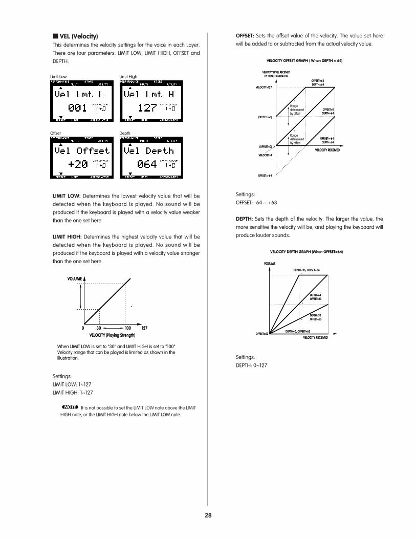
28
OFFSET: Sets the offset value of the velocity. The value set herewill be added to or subtracted from the actual velocity value.
Settings:OFFSET: -64 ~ +63
DEPTH: Sets the depth of the velocity. The larger the value, themore sensitive the velocity will be, and playing the keyboard willproduce louder sounds.
Settings:DEPTH: 0~127
VELOCITY DEPTH GRAPH (When OFFSET=64)
OFFSET=63
VOLUME
DEPTH=96, OFFSET=64
DEPTH=64OFFSET=63
DEPTH=32OFFSET=63
DEPTH=0, OFFSET=63
VELOCITY RECEIVED
VELOCITY OFFSET GRAPH ( When DEPTH = 64)
VELOCITY RECEIVED
OFFSET=-64DEPTH=64
VELOCITY LEVEL RECEIVEDBY TONE GENERATOR
(OFFSET=63)
(OFFSET=0)
OFFSET=-64
OFFSET=0DEPTH=64
OFFSET=63DEPTH=64
VELOCITY=127
VELOCITY=1
Rangedeterminedby offset
Rangedeterminedby offset
VEL (Velocity)This determines the velocity settings for the voice in each Layer.There are four parameters: LIMIT LOW, LIMIT HIGH, OFFSET andDEPTH.
LIMIT LOW: Determines the lowest velocity value that will bedetected when the keyboard is played. No sound will beproduced if the keyboard is played with a velocity value weakerthan the one set here.
LIMIT HIGH: Determines the highest velocity value that will bedetected when the keyboard is played. No sound will beproduced if the keyboard is played with a velocity value strongerthan the one set here.
Settings:LIMIT LOW: 1~127LIMIT HIGH: 1~127
It is not possible to set the LIMIT LOW note above the LIMITHIGH note, or the LIMIT HIGH note below the LIMIT LOW note.
NOTE
VELOCITY (Playing Strength)
VOLUME
0 30 100 127
When LIMIT LOW is set to "30" and LIMIT HIGH is set to "100"Velocity range that can be played is limited as shown in theillustration.
Limit Low Limit High
Offset Depth

29
ASSIGN2This sets the control parameter and knob sensitivity of theASSIGN 2 Sound Control Knob. It is possible to assign up to fourparameters from 28 types. It is also possible to set the sensitivity(control range of the knob) for each parameter.The parameter assigned to the ASSIGN2 knob as the defaultdiffers depending on the Performance selected.
1. Select the Layer.Press the LAYER [-]/[+] button to select the Layer to which youwant to assign a parameter.
2. Select the item (parameter type or sensitivity) you wantto edit and the assignment number which you want toassign the parameter to.
Press the Parameter Value [UP] button to select the item(parameter type or sensitivity) you want to edit, and theassignment number. Each t ime you press the (PARAM)Parameter Value [UP] button, the arrow cursor will move asshown in the following illustration.
Each time you press the (PARAM) Parameter [DOWN] button, thearrow cursor will move in the opposite direction.
3. Move the cursor to the Parameter type area and pressthe (DATA) Parameter UP/DOWN button to select theparameter type.
Settings:The following parameters can be assigned to assignmentnumber 1 ~ 4. For details about each parameter, see thereference pages as listed below.
When voices are not assigned to the Layers (Bank=Off),Parameter type and sensitivity will not display.
NOTE
Parameter type of assignment number 1 ↓↓↓↓↓↓↓↓
↑
Sensitivity of assignment number 1 ↑
Parameter type of assignment number 2 ↑
Sensitivity of assignment number 2 ↑
Parameter type of assignment number 3 ↑
Sensitivity of assignment number 3 ↑
Parameter type of assignment number 4 ↑
Sensitivity of assignment number 4 ↑
Parameter Type
Layer
Assignment NumberSensitivity
Parameter with an asterisk cannot be modified, but you can assign it tothe ASSIGN2 knob.
Each parameter can also be selected by inputting the number with thenumeric keypad.
4. Press the (PARAM) Parameter Value UP/DOWN button tomove the arrow cursor to the sensitivity area.
5. Press the (DATA) Parameter Value UP/DOWN button toset the knob sensitivity.
Settings:Parameters can be set between -32 and +32, for assignmentnumbers 1 ~ 4.
As an example, say you have selected the Volumeparameter and set the knob sensitivity to the positive value "+32". Thevolume is "0" when the knob is turned counter-clockwise to the farleft, and "127" when the knob is turned clockwise to the far right.If the knob sensitivity is set to the negative value "-32", the volume is"127" when the knob is turned to the far left and "0" when the knob isturned to the far right. If the sensitivity value is small, the control rangeof the knob will be narrowed and limited.
6. Repeat the above steps to set a different parameter/knobsensitivity value to each of the four assignment numbers.
When the PARAM screen is displayed, you can select theparameter type or change the sensivity using the Data Entry knob orthe numeric keypad.
NOTE
NOTE
# LCD0 off1 Volume (page 33)2 NoteShift (page 27)3 Detune (page 27)4 Pan (page 34)5 ChorusSend (page 38)6 ReverbSend (page 38)7 *Pitch (Oscillator Pitch)8 VelSnsDpth (Velocity Sensitivity Depth) (page 28)9 VelSnsOfst (Velocity Sensitivity Offset) (page 28)
10 Cutoff (Filter Cuttoff Frequency) (page 34)11 Resonance (page 34)12 AEGAtkTime (AEG Attack Time) (page 30)13 AEGDcyTime (AEG Decay Time) (page 30)14 AEGSusLvl (AEG Sustain Level) (page 30)15 AEGRelTime (AEG Release Time) (page 30)16 LFOSpeed (LFO Speed) (page 31)17 LFOAMod (LFO Amplitude Modulation Depth) (page 30)18 LFOPMod (LFO Pitch Modulation Depth) (page 30)19 LFOFMod (LFO Filter Modulation Depth) (page 31)20 FEGAtkTime (FEG Attack Time) (page 32)21 FEGDcyTime (FEG Decay Time) (page 32)22 FEGSusLvl (FEG Sustain Level) (page 32)23 FEGRelTime (FEG Release Time) (page 32)24 PEGInitLvl (PEG Initial Level) (page 32)25 PEGAtkTime (PEG Attack Time) (page 32)26 PEGAtkLvl (PEG Attack Level) (page 32)27 PEGDcyTime (PEG Decay Time) (page 32)28 PEGRelTime (PEG Release Time) (page 32)29 PEGRelLvl (PEG Release Level) (page 32)

30
Settings:ATK TIME (Attack Time): -63 ~ +63DCY TIME (Decay Time): -63 ~ +63SUS LEVEL (Sustain Level): -64 ~ +63REL TIME (ReleaseTime): -63 ~ +63
LFO (Low Frequency Oscillator)This sets the parameters for the LFO (Low Frequency Oscillator).The LFO is an oscillator that generates low frequency signalsused to modulate certain aspects of the sound such as pitch,volume or f i l ter level. There are six parameters: AMOD(Amplitude Modulation), PMOD (Pitch Modulation), FMOD (FilterModulation), WAVE, SPEED and PHASE INIT.
AMOD (Amplitude Modulation): Adds a cyclical change to thevolume level by applying LFO frequency modulations, to create atremolo effect. Larger values widen the range of the volumechange.
PMOD (Pitch Modulation): Adds a cyclical change to the pitchby applying LFO frequency modulations, to create a vibratoeffect. Larger values widen the range of the pitch change.
Amplitude Modulation Pitch Modulation
Filter Modulation Wave
Speed Phase Init
Key On Key Off
ATK TIME REL TIMEDCY TIME
SUSLEVEL
TIME
VOLUMELayer Edit 2 (independently applied to each Layer)The functions in this row provide parameters which are essentialin creating a voice, such as AEG (Amplitude Envelope Generator)and LFO (Low Frequency Oscillator). The parameters can be setfor each Layer in a Performance.
AEG (Amplitude Envelope Generator)This sets the AEG (Amplitude Envelope Generator). The AEG letsyou shape how the volume level changes over time, from whena key is hit, then released, and how the sound decays. There arefour parameters: ATK TIME (Attack Time), DCY TIME (Decay Time),SUS LEVEL (Sustain Level) and REL TIME (Release Time).
Each musical instrument has a unique envelope curvewhich plays an important role in determining its sound characteristics.The AEG simulates the change of the volume envelope curve overtime.
Depending on the voice selected, changing certainparameters may not produce a noticeable effect.
ATK TIME (Attack Time): Determines the time required for asound to reach its maximum volume level when a note isplayed.
DCY TIME (Decay Time): Determines the time required for asound to reach its Sustain Level from a maximum volume levelwhile the key is held.
SUS LEVEL (Sustain Level): Sets the Sustain Level. The volumewill be maintained at this level for as long as the key is held.
REL TIME (Release Time): Determines the time it takes for asound to sustain after the key has been released.
Attack Time Decay Time
Sustain Level Release Time
NOTE
NOTE
PERFORMANCE MULTI
DEMO
STORE UTILITY
BANK
ATKTIME
ATKTIME
PROGRAM
SYSTEM MIDI ASSIGN
DCYTIME
DCYTIME
VOLUME
LFO
PEG
AEG
FEG
SUSLEVEL
DCYLEVEL
PAN
RELTIME
RELTIME
REVSEND
AMOD
INITLEVEL
CHOSEND
PMOD
ATKTIME
EFFECTVARISEND
FMOD
ATKLEVEL
CUTOFFFILTER
WAVE
DCYTIME
REZ
SPEED
RELTIME
POLY/MONO
PHASEINIT
RELLEVEL
LAYER

31
FMOD (Filter Modulation): Adds a cyclical change to the filtercutoff frequency by applying LFO frequency modulations, tocreate wah-wah type effects. Larger values widen the range ofcutoff frequency change.
WAVE: Selects the LFO frequency signal used for modulation.You can select from the following types:
SPEED: Sets the speed of the LFO frequency modulation. Largervalues increase the speed.
PHASE INIT: Determines if the phase of the LFO frequencymodulation wave is reset or not when a note is played. Thereare three types: Free, Retr (Retrigger) and Elem (Element).
Free: The wave starts at the phase position where a note is played.
TIME
KEY ON
+
0
–
TIME
+
0
–
Retr (Retrigger): The wave starts at +/-0 phase position.
Phase whenkeyboard isplayed
KEY ON
Elem (Element): The wave starts from the default phase position (Free or Retr) for each element of the voices.
TIME
SLOW
FAST
TIME
TIMESaw (Sawtooth)
Tri (Triangle)
S&HTr (Sample & Hold = random)
*S&HTr = Adds random changes to the pitch. (NOTE: Triangle waves will be applied for the AMOD and FMOD. Triangle wave is applied even if you select S&HTr for PMOD, whencontrolling the PMOD with the Modulation Wheel.)
ELEM (Element)*Default settings of each element depending on the selected voice.
TIME
TIME
Settings:AMOD (Amplitude Modulation): -31 ~ +31PMOD (Pitch Modulation): -63 ~ +63FMOD (Filter Modulation): -15 ~ +15WAVE: Saw, Tri , S&HTr, ElemSPEED: -63 ~ +63PHASE INIT: Free, Retr, Elem
Layer Edit 3 (independently applied to each Layer)The functions in this row provide parameters which are essentialin creating a voice, such as FEG (Filter Envelope Generator) orPEG (Pitch Envelope Generator). The parameters can be set foreach Layer in a Performance.
FEG (Filter Envelope Generator)This sets the FEG (Filter Envelope Generator). The FEG lets youshape how the tone, or timbre, of the voice changes over time,from when a key is hit, then released, and how the sounddecays. There are four parameters: ATK TIME (Attack Time), DCYTIME (Decay Time), SUS LEVEL (Sustain Level) and REL TIME(Release Time).
Generally, filters change the timbre by passing signalswithin a specific frequency bandwidth and cutting others. The CS1xfeatures an LPF (Low Pass Filter) which passes the signals below thespecified frequency point (cutoff frequency) and cuts the signalsabove it (see page 34). The FEG simulates the change of the filterenvelope curve over time.
Depending on the voice selected, changing certainparameters may not produce a noticeable effect.
NOTE
NOTE
PERFORMANCE MULTI
DEMO
STORE UTILITY
BANK
ATKTIME
PROGRAM
SYSTEM MIDI ASSIGN
DCYTIME
VOLUME
PEGFEGSUS
LEVEL
PAN
RELTIME
REVSEND
INITLEVEL
CHOSEND
ATKTIME
EFFECTVARISEND
ATKLEVEL
CUTOFFFILTER
DCYTIME
REZ
RELTIME
POLY/MONO
RELLEVEL
LAYER

32
PEG (Pitch Envelope Generator)This sets the PEG (Pitch Envelope Generator). The PEG lets youshape how the pitch of the voice changes over time, from whena key is hit, then released, and how the sound decays. There aresix parameters: INIT LEVEL (Initial Level), ATK TIME (Attack Time),ATK LEVEL (Attack Level), DCY TIME (Decay Time), REL TIME(Release Time) and REL LEVEL (Release Level).
Since the PEG simulates the change of the pitch envelopecurve over time, you can create an SFX type effect and the slight pitchchange of a wind instrument.
Depending on the voice selected, changing certainparameters may not produce a noticeable effect.
INIT LEVEL (Initial Level): Sets the initial pitch level when a key isplayed.
ATK TIME (Attack Time): Determines the time required for asound to reach its Attack Level after a note is played.
ATK LEVEL (Attack Level): Sets the initially targeted level after anote is played.
DCY TIME (Decay Time): Determines the time required for a sound toreach its basic pitch from Attack Level while the key is held.
REL TIME (Release Time): Determines the time it takes for the basicpitch to reach the Release Level after the key has been released.
REL LEVEL (Release Level): Sets the last targeted level after thekey is released.
Initial Level Attack Time
Attack Level Decay Time
Release Time Release Level
NOTE
NOTE
ATK TIME (Attack Time): Determines the time required for asound to reach its maximum cutoff frequency level when a noteis played.
DCY TIME (Decay Time): Determines the time required for asound to reach its Sustain Level from a maximum level while thekey is held.
SUS LEVEL (Sustain Level): Sets the Sustain Level. The cutofffrequency will be maintained at this level for as long as the keyis held.
REL TIME (Release Time): Determines the time it takes for thecutoff frequency to reach the level preset for each voice after thekey has been released.
Settings:ATK TIME (Attack Time): -63 ~ +63DCY TIME (Decay Time): -63 ~ +63SUS LEVEL (Sustain Level): -64 ~ +63REL TIME (Release Time): -63 ~ +63
Key On
CUTOFFFREQUENCY
Key Off
ATK TIME REL TIMEDCY TIME
TIME
LEVEL
SUSLEVEL
Attack Time Decay Time
Sustain Level Release Time

33
Settings:INIT LEVEL (Initial Level): -64 ~ +63ATK TIME (Attack Time): -63 ~ +63ATK LEVEL (Attack Level: -64 ~ +63DCY TIME (Decay Time): -63 ~ +63REL TIME (Release Time): -63 ~ +63REL LEVEL (Release Level): -64 ~ +63
Layer Edit 4 (independently applied to each Layer)The functions in this row provide parameters which includefundamental settings such as voice assignment, volume andpanning settings for each Layer. The parameters can be set foreach Layer in a Performance.
BANKThis lets you select a Bank, each of which contains up to 128normal voices. To select a voice, you must first select a Banknumber, and then select a Program number in the PROGRAMparameter, explained below.
Settings: off, XG000, 001, 003, 006, 008, 012, 014, 016~020, 024,025, 027, 028, 032~043, 045, 064~072, 096~101, SFX, PRE 0~12(for Performance only)
PERFORMANCE MULTI
DEMO
STORE UTILITY
BANK PROGRAM
SYSTEM MIDI ASSIGN
VOLUME PAN REVSEND
CHOSEND
EFFECTVARISEND
CUTOFFFILTER
REZPOLY/MONO
LAYER
UTILITY
Key On
PITCH
INIT LEVEL
ATK LEVEL
REL LEVEL
Key Off
ATK TIME REL TIMEDCY TIME
TIME
LEVEL
Basic Pitch
Each bank can be selected directly by inputting the correspondingBank number using the numeric keypad.
For more information about Banks and Programs (voices),see the Voice List in the "Data List" book.
PROGRAMThis lets you select a voice, or program, from the Bank previouslyselected with the BANK parameter, explained above.
Settings:1~128
Note that the Program numbers here are 1~128 and theMIDI Program Change numbers are 0~127. To match the MIDIProgram Change number when switching programs using anexternal MIDI device, subtract a value of "1" from the Programnumber.
For more information about Banks and Programs (voices),see the Voice List in the "Data List" book.
VOLUMEThis sets the volume of each Layer. It is possible to assign adifferent volume setting for each Layer.
Settings:0~127
NOTE
NOTE
NOTE
MSB LSB Bank LCD Remarks0 0 0 XG000 XG0 1 1 XG001
0 101 101 XG10164 0 102 SFX XG63 0 103 PRE0 for Performance Only63 1 104 PRE1
63 7 110 PRE76363
812
111115
PRE8PRE12
- - 999 off
Bank Conversion Table for Voices Used in Performances
↓↓↓↓↓↓↓
↓↓↓↓
↓
↓↓↓
for Performance Only

34
The value of some Layers may forcibly be changed whenusing the Variation effect.
For more information, see page 47.
FILTERThis sets the filter parameters for each Layer. There are twoparameters, CUTOFF and REZ (Resonance).
Generally, filters change the timbre by passing signalswithin a specific frequency bandwidth and cutting others. The CS1xfeatures an LPF (Low Pass Filter) which passes the signals below thespecified frequency point (cutoff frequency) and cuts the signalsabove it.
Depending on the voice selected, changing certainparameters may not produce a noticeable effect.
CUTOFF: Determines the cutoff frequency of the filter, or thefrequency point above which other frequencies are filtered out.Higher settings result in brighter tones and lower settings resultin darker tones.
REZ (Resonance): Sets the amount of filter resonance oremphasis around the cutoff frequency. Higher settings producea higher resonant peak, while lower settings produce a relativelyflat response.
Settings:CUTOFF: -64 ~ +63REZ (Resonance): -64 ~ +63
FREQUENCY
VOLUME
CUTOFF FREQUENCY
RESONANCE
FREQUENCY
VOLUME
CUTOFF FREQUENCY
FREQUENCIES CUT
FREQUENCIES PASSED
NOTE
NOTE
Cutoff Resonance
NOTE
NOTE PANThis sets the panning (the left or right position in the stereospectrum) of each Layer. Different pannings can be set for eachLayer, thus providing for a richly textured stereo image (forstereo output).
Settings:Random, L63 (far left in the stereo image) to L01 to C00 (center inthe stereo image) to R01 to R63 (far right in the stereo image)
When set to "Random", the pan position of each Layer willalternate between left and right each time a Performance is played.
Some of the voices are preset and have a fixed panning of"left" in the lower register and "right" in the higher register. In such acase, you cannot modify the pan setting.
EFFECTThis sets the effect send (output) level of each Layer. There arethree parameters: REV SEND (Reverb Send), CHO SEND (ChorusSend) and VARI SEND (Variation Send). Each effect send level sethere will be output to the Reverb, Chorus, and Variation effectsections as previously selected (see page 23).
REV SEND (Reverb Send): Determines the send level of theReverb effect.
CHO SEND (Chorus Send): Determines the send level of theChorus effect.
VARI SEND (Variation Send): Enables or disables the output ofthe Variation effect.
Settings:REV SEND (Reverb Send): 0~127CHO SEND (Chorus Send): 0~127VARI SEND (Variation Send): OFF, ON
Reverb Send Chorus Send
Variation Send
NOTE
NOTE
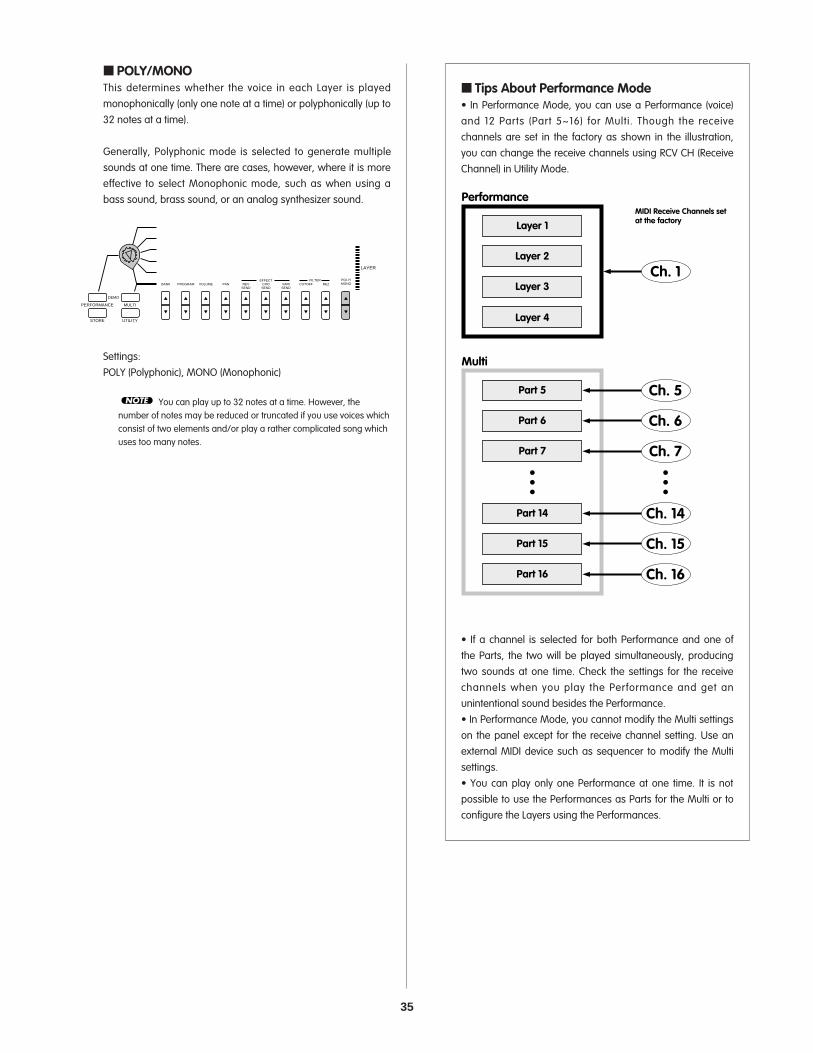
35
POLY/MONOThis determines whether the voice in each Layer is playedmonophonically (only one note at a time) or polyphonically (up to32 notes at a time).
Generally, Polyphonic mode is selected to generate multiplesounds at one time. There are cases, however, where it is moreeffective to select Monophonic mode, such as when using abass sound, brass sound, or an analog synthesizer sound.
Settings:POLY (Polyphonic), MONO (Monophonic)
You can play up to 32 notes at a time. However, thenumber of notes may be reduced or truncated if you use voices whichconsist of two elements and/or play a rather complicated song whichuses too many notes.
NOTE
PERFORMANCE MULTI
DEMO
STORE UTILITY
BANK PROGRAM
SYSTEM MIDI ASSIGN
VOLUME PAN REVSEND
CHOSEND
EFFECTVARISEND
CUTOFFFILTER
REZPOLY/MONO
LAYER
Tips About Performance Mode• In Performance Mode, you can use a Performance (voice)and 12 Parts (Part 5~16) for Multi. Though the receivechannels are set in the factory as shown in the illustration,you can change the receive channels using RCV CH (ReceiveChannel) in Utility Mode.
• If a channel is selected for both Performance and one ofthe Parts, the two will be played simultaneously, producingtwo sounds at one time. Check the settings for the receivechannels when you play the Performance and get anunintentional sound besides the Performance.• In Performance Mode, you cannot modify the Multi settingson the panel except for the receive channel setting. Use anexternal MIDI device such as sequencer to modify the Multisettings.• You can play only one Performance at one time. It is notpossible to use the Performances as Parts for the Multi or toconfigure the Layers using the Performances.
Performance
Layer 1
Layer 2
Layer 3
Layer 4
Ch. 1
Multi
Part 5
Part 6
Part 7
Ch. 5
Ch. 6
Ch. 7
Part 14
Part 15
Part 16
Ch. 14
Ch. 15
Ch. 16
MIDI Receive Channels set at the factory

36
Editing Procedures1. Select a Part.Use the PART [-]/[+] button to select the Part you want to edit.
2. Select the parameter.Press the Parameter Value UP/DOWN button corresponding tothe parameter you want to edit once to select the parameterand display the settings.
3. Set the value.Press the Parameter Value UP/DOWN button again to set thevalue. Holding the Parameter Value UP/DOWN button changesthe value continuously. The [UP] button increases the value andthe [DOWN] button decreases the value.
You can also use the numeric keypad (0~9) or the DataEntry knob to change the value.
To change the value for all Parts at one time, hold SHIFTand press the Parameter Value UP/DOWN button. When you pressSHIFT in Multi Part Edit, a letter "A" (All) will appear in the LCD belowthe word "PART".
Other parameters will appear in the LCD when you pressthe other Parameter Value UP/DOWN buttons. Continue setting theother parameters.
To exit from the Multi Part Edit, press the MULTI buttonagain. The display will return to the Voice name screen. You can alsoexit Multi Play mode by pressing the PERFORMANCE button to enterPerformance mode.
NOTE
NOTE
ARPEGGIO HOLD SHIFT
OCTAVEPART/LAYER/
+
PRESET USER
PROGRAM
+
NOTE
NOTE
PERFORMANCE MULTI
DEMO
STORE UTILITY
TYPE
BANK
P BENDRANGE
NOTESFT
ATKTIME
ATKTIME
TEMPOGG O O
LEVELC
PROGRAM
SYSTEM MIDI ASSIGN
PMOD
DETUNE
DCYTIME
DCYTIME
SUBDIVIDE
VOLUME
FMOD
REVTYPE
CUTOFFFC PORTA
VEL ASSIGN2
LFO
PEG
CHOTYPE
VARIEF
VARITYPE
SWITCH
VARIPARAM
TIME
VARIDATA
MWFMOD
LIMITLOW
TUNE
AEG
FEG
NOTE
DCYLEVEL
DCYLEVEL
PAN
CUTOFF
LIMITHIGH
RELTIME
RELTIME
REVSEND
LIMITLOW
AMOD
INITLEVEL
CHOSEND
LIMITHIGH
PMOD
ATKTIME
EFFECTVARISEND
OFFSET
FMOD
ATKLEVEL
CUTOFFFILTER
DEPTH
WAVE
DCYTIME
REZ
PARAM
SPEED
RELTIME
NAME
POLY/MONO
ASSIGN1PARAM
DATA
PHASEINIT
RELLEVEL
C
LA
ARPEGGIO HOLD SHIFT
OCTAVEPART/LAYER/
+
PRESET USER
PROGRAM
+Entering Multi Play ModePress the MULTI button. A [] mark will appear below theword "MULTI" in the LCD.
Playing the keyboard will play the voice of the Part currently displayedin the LCD. The Category name for the selected voice will be shownnext to the voice name.
You can also select a voice from the XG000 (GM) Bank by pressingthe PROGRAM [-]/[+] buttons.
When you enter Multi Play mode from Performance mode,the CS1x automatically resets the internal tone generator to XG ON(001 Grand Piano) status.
Multi Part EditYou can edit each Part in realtime. You can assign a voice to each Partand set the volume, pan and effect. These settings are temporary andcannot be stored. Therefore, entering Performance mode will clear this data.
76
54
32
1
Part 1-16
BANKPROGRAMVOLUMEPANEFFECTFILTERPOLY/MONO
NOTE
PERFORMANCE MULTI
DEMO
STORE UTILITY
Part Number
Voice NumberCategory
Program (Voice) Number
MIDI Data
PART 1~16
(1~16ch)
ExternalMIDI Sequencer
MULTI PART EDITXG voices, volume, pan,effect and other settings.
In Multi Play mode you can play up to 16 Parts using an external MIDI sequencer. This mode is mainly used when the CS1x is used as an XG-compatible tone generator or as a data input device in a computer music system. You can use any XG voice from the 480 normal voices and 11 drum voices. When playing back from or recording to an external sequencer, you can use the Multi Part Edit function to edit the volume and effect of each Part.

37
Description of Each Function BANKThis lets you select a Bank. Various normal voice bankscontaining up to 128 normal voices, a bank with different drumvoices (kits), plus SFX banks are available to choose from. Toselect a voice, you must first select a Bank number, and thenselect a Program number in the PROGRAM parameter,explained below.
Settings:off, XG000, 001, 003, 006, 008, 012, 014, 016~020, 024, 025, 027, 028,032~043, 045, 064~072, 096~101, SFX, SFXKIT, DRUM
Each bank can be selected directly by inputt ing thecorresponding number with the numeric keypad.
For more information about Banks and Programs (voices),see the XG Voice List in the "Data List" book.
PROGRAMThis lets you select a voice, or program, from the Bankpreviously selected with the BANK parameter, explained above.
Settings:1~128
Note that the Program numbers here are 1~128 and theMIDI Program Change numbers are 0~127. When switching programsusing an external MIDI device, subtract a value of "1" from theProgram number to match the MIDI Program Change number.
For more information about Banks and Programs (voices),see the XG Voice List in the "Data List" book.
NOTE
NOTE
NOTE
Bank Conversion Table for Multi
MSB LSB Bank LCD0 0 0 XG0000 1 1 XG001
↓↓↓↓
0 101 101 XG10164 0 102 SFX
126 0 126 SFXKIT127 0 127 DRUM
Off- - 999
It is also possible to change the Program number quickly byusing the Quick Program Change function, the same way as inPerformance mode. For details, see page 21.
Normal Voices and Drum VoicesThe available voices are divided into two groups: normal voicesand drum voices. In Multi Play mode you can select and play bothnormal and drum voices.
In general a "normal" voice is simply a pitched voice which can beplayed on a musical scale from low to high, such as a piano ortrumpet. In Multi Play mode there are 480 XG normal voices.
A "drum" voice is a complete set of drum and other percussionsounds, each sound having a fixed pitch. Each sound is assignedto a specific MIDI Note number which also corresponds to a key ona MIDI keyboard. In Multi Play mode there are 11 XG drum voices.For a list of the drum and percussion sound assignments to eachkey, see the XG Drum Voice List in the "Data List" book.
TG300B ModeThere are two tone generator modes: XG mode and TG300Bmode. Normally the CS1x plays in XG mode. However, itautomatically recognizes which mode to select based on incomingMIDI data, i.e., through MIDI System Exclusive messages that youcan program using an external MIDI sequencer.
In TG300B mode the CS1x will play multitimbral music data createdfor TG300B-compatible tone generators. TG300B mode alsoprovides compatibility with the GM System Level1 format.
In TG300B mode the CS1x can:• Play up to 16 Parts.• Choose from 579 Normal Voices and 10 Drum Voices.
VOLUMEThis sets the volume of each Part. Different volume levels can beset for each Part.
Settings:0~127
NOTE

38
REV SEND (Reverb Send): Determines the send level of theReverb effect.
CHO SEND (Chorus Send): Determines the send level of theChorus effect.
VARI SEND (Variation Send): Enables or disables the output ofthe Variation effect.
Settings:REV SEND (Reverb Send): 0~127CHO SEND (Chorus Send): 0~127VARI SEND (Variation Send): OFF, ON (or 0~127)
The Variation send parameters are OFF or ON when theVariation effect is used as the Insertion effect. They are 0~127 whenused as the System effect. Normally, the Variation effect works as anInsertion Effect when not receiving parameter change messages toswitch to System Effect from an external MIDI sequencer. For moreinformation about Insertion and System effects, see page 47.
FILTERThis sets the parameters of the filter for each Part. There are twoparameters, CUTOFF and REZ (resonance).
Generally, filters change the timbre by passing signals within aspecific frequency bandwidth and cutting others. The CS1xfeatures an LPF (Low Pass Filter) which passes the signals belowthe specified frequency point (cutoff frequency) and cuts thesignals above it.
Depending on the voice selected, changing certainparameters may not produce a noticeable effect.
CUTOFF: Determines the cutoff frequency of the filter, or thefrequency point above which other frequencies are filtered out.Higher settings result in brighter sounds and lower settingsresult in darker sounds.
REZ (Resonance): Sets the amount of filter resonance oremphasis around the cutoff frequency. Higher settings producea higher resonant peak, while lower settings produce a relativelyflat response.
Settings:CUTOFF: -64 ~ +63REZ (Resonance): -64 ~ +63
NOTE
4DEF
1ABC
0
Cutoff Resonance
NOTE
PANThis sets the panning (the left or right position in the stereospectrum) for each Part. Different pannings can be set for eachPart (for stereo output).
Settings:Random, L63 (far left in the stereo image) to L01 to C00 (center ofa stereo image) to R01 to R63 (far right in the stereo image)
When set to "Random", the panning of each Part willalternate between left and right each time a voice is played.
Some of the voices are preset and fixed to a panning of"left" in the lower register and "right" in the higher register. In such acase, you cannot modify the pan setting.
EFFECTThis sets the effect send (output) level for each Part. There arethree parameters: REV SEND (Reverb Send), CHO SEND (ChorusSend) and VARI SEND (Variation Send). You can change the effectsend level for each effect in realtime when you are playing backXG song data containing effect settings using an external MIDIdevice.
When you enter Multi Play mode (reset to XG ON) bypressing the MULTI button, each effect will be reset to the defaultsettings: Hall 1 (Reverb), Chorus 1 (Chorus) and Delay L,C,R (Variation).In this case, the Reverb send level is set to 64, and the Chorus andVariation send levels are set to 0.
Depending on the XG song data being played, the effect typesand their parameters used in the song may differ.
Note that the effect types and their parameters in thePerformance Edit mode have no relation to the effect settingshere.
Reverb Send Chorus Send
Variation Send
NOTE
NOTE
NOTE
39
POLY/MONOThis determines whether the voice in each Layer is playedmonophonically (only one note at a time) or polyphonically (up to32 notes at a time).
Generally, Polyphonic mode is selected to generate multiplesounds at one time. There are cases, however,where it is moreeffective to select Monophonic mode, such as when using abass sound, brass sound, or an analog synthesizer sound.
Settings:POLY (Polyphonic), MONO (Monophonic)
You can play up to 32 notes at a time. However, thenumber of notes may be reduced or truncated if you use voices whichconsist of two elements and/or play a rather complicated song whichuses too many notes.
Using the Multi Play Mode• Multi Play Mode is specifically aimed at playing CS1x as atone generator using the external device such as sequencer.Consequently, the changes made in Multi Play Mode aretemporary and cannot be stored.• The Arpeggiator function is not available in Multi PlayMode. It can only be applied to the Performances inPerformance Mode.
NOTE
PERFORMANCE MULTI
DEMO
STORE UTILITY
BANK PROGRAM
SYSTEM MIDI ASSIGN
VOLUME PAN REVSEND
CHOSEND
EFFECTVARISEND
CUTOFFFILTER
REZPOLY/MONO
U

40
Other parameters will appear in the LCD when you pressthe other Parameter Value UP/DOWN buttons. Continue setting theother parameters.
Press the PERFORMANCE button or the MULTI button to exitUtility mode and return to each respective mode.
It is not necessary to store changes made in the Utilitymode. The CS1x will remember any changes you make in this mode.
Description of Each FunctionSYSTEMThis sets the tuning and other keyboard settings for the CS1xtone generator. There are four parameters: MASTER TUNE, KBDTRANS (Keyboard Transpose), VEL CURVE (Velocity Curve) andVEL FIX (Velocity Fix).
MASTER TUNEThis tunes the CS1x's tone generator. Basic pitch is 440 Hz atnote A3. Master tuning can be adjusted 1 Hz at a time.
Settings:-102 Hz to 0 (A3=440 Hz) to +102 Hz
KBD TRANS (Keyboard Transpose)This lets you transpose the pitch in semitones. The transposevalue will also be reflected in the Octave Shift function on thepanel.
Settings:-36 to 0 (standard) to +36
This function setting is related to OCTAVE SHIFT on thepanel, the indication may be changed after using the OCTAVE SHIFTfunction.
NOTE
NOTE
NOTE
NOTE
Entering Utility ModePress the UTILITY button. A [] mark appears in the LCDbelow the word "UTILITY".
The LCD will display the parameter settings previouslyselected in Utility mode. The first time you press the UTILITY buttonafter turning the power on, the LCD will display the first page (MasterTune) in Utility mode.
Procedure1. Select the parameter.
Press the Parameter Value UP/DOWN button corresponding to theparameter you want to edit once to select the parameter and displaythe settings in the LCD.
2. Set the value.Press the Parameter Value UP/DOWN button again to set the value.Holding the Parameter Value UP/DOWN button changes the valuecontinuously. The [UP] button increases the value and the [DOWN]button decreases the value.
You can also use the numeric keypad (0~9) or the DataEntry knob to change the value.
NOTE
PERFORMANCE MULTI
DEMO
STORE UTILITY
BANK
TIME
MASTERTUNE
PROGRAM
SYSTEM MIDI
TIME
KBDTRANS
VOLUME
LEVEL
VELCURVE
PAN
TIME
VELFIX
REVSEND
LEVEL
TRANSCH
CHOSEND
TIMEEFFECT
RCVCH
VARISEND
LEVEL
DEVICENO
PERFORMANCE MULTI
DEMO
STORE UTILITY
BANK
TIME
MASTERTUNE
PROGRAM
SYSTEM MIDI
TIME
KBDTRANS
VOLUME
LEVEL
VELCURVE
PAN
TIME
VELFIX
REVSEND
LEVEL
TRANSCH
CHOSEND
TIMEEFFECT
RCVCH
VARISEND
LEVEL
DEVICENO
NOTE
PERFORMANCE MULTI
DEMO
STORE UTILITY
Parameter Name
SYSTEM SETTINGSMASTER TUNE
KBD TRANSVEL CURVE
VEL FIX
MIDI SETTINGSTRANS CH
RCV CHDEVICE NO
LOCALBULK DUMP
CS1x CS1x
MIDI
ASSIGN CONTROLCHANGER NUMBER
In Utility mode you can set the CS1x system and MIDI parameters.
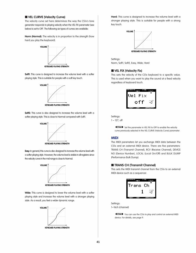
41
VEL CURVE (Velocity Curve)The velocity curve set here determines the way the CS1x's tonegenerator responds to playing velocity when the VEL FIX parameter (seebelow) is set to OFF. The following six types of curves are available:
Norm (Normal): The velocity is in proportion to the strength (howhard you play the keyboard).
Soft1: This curve is designed to increase the volume level with a softerplaying style. This is suitable for people with a soft key touch.
Soft2: This curve is also designed to increase the volume level with asofter playing style. This is close to Normal compared with Soft1.
Easy: In general, this curve is also designed to increase the volume level witha softer playing style. However, the volume level is stable in all registers sincethe velocity curve in the mid range is close to Normal.
Wide: This curve is designed to lower the volume level with a softerplaying style and increase the volume level with a stronger playingstyle. As a result, you feel a wider dynamic range.
KEYBOARD PLAYING STRENGTH
VOLUME
KEYBOARD PLAYING STRENGTH
VOLUME
KEYBOARD PLAYING STRENGTH
VOLUME
KEYBOARD PLAYING STRENGTH
VOLUME
KEYBOARD PLAYING STRENGTH
VOLUME
Hard: This curve is designed to increase the volume level with astronger playing style. This is suitable for people with a strongkey touch.
Settings:Norm, Soft1, Soft2, Easy, Wide, Hard
VEL FIX (Velocity Fix)This sets the velocity of the CS1x keyboard to a specific value.This is used when you want to play the sound at a fixed velocityregardless of keyboard touch.
Settings:1 ~ 127, off
Set the parameter in VEL FIX to OFF to enable the velocitycurve previously selected in the VEL CURVE (Velocity Curve) parameter.
MIDIThe MIDI parameters let you exchange MIDI data between theCS1x and an external MIDI device. There are five parameters:TRANS CH (Transmit Channel), RCV (Receive Channel), DEVICENO (Device Number), LOCAL (Local On/Off) and BULK DUMP(Performance Bulk Dump).
TRANS CH (Transmit Channel)This sets the MIDI transmit channel from the CS1x to an externalMIDI device such as a sequencer.
Settings:1~16ch (channel)
You can use the CS1x to play and control an external MIDIdevice. For details, see page 9.
NOTE
NOTE
KEYBOARD PLAYING STRENGTH
VOLUME

42
BULK DUMP (Performance Bulk Dump)This lets you send Performance data from the CS1x in bulk toanother CS1x or to the Yamaha MIDI Data Filer MDF2. This isconvenient for backing up, storing, or managing your importantPerformance data.
To enable transmission, first connect the MIDI devices. (Fordetails about setting up each device, see the respective owner'smanuals of the external MIDI devices.) It is necessary to match thedevice number of the CS1x with the device number of the externalMIDI device. (See the DEVICE NO parameter, above.)
Bulk Dump Send1.Select the type of data you want to send by pressing the
Parameter Value UP/DOWN button. You can select from thefollowing types:
1Perf: The Preset or User Performance data currently selected inPerformance mode.all: All of the User Performance data and the System data.
2.Press the ENTER/YES button to execute the bulk dumpoperation. "End" will appear in the LCD when the operation iscompleted, and the LCD will return to the original display.
Bulk Dump ReceiveThis lets you retrieve CS1x Performance data from an externaldevice, loading it back into the CS1x in bulk.
The data that can be received will differ depending on the mode.For details about the MIDI data format, see the "Data List" book.It is necessary to match the device number of the CS1x with thedevice number of the external MIDI device. (See the DEVICE NOparameter, above.)
VWX
7
YZ'
8
&*
9MNO
4
PQR
5
STU
6DEF
1
GHI
2
JKL
NO/QUICK PC
YES
3ABC
0
SPACE
ENTER
NOTE
RCV CH (Receive Channel)In Performance Mode, this sets the MIDI receive channel forcontrolling the CS1x with an external device such as a MIDIsequencer or computer.
In Multi Play mode, the CS1x resets the internal tone generator toXG ON (001 Grand Piano) status and automatically receives theexternal data.
Settings:LAYER A (Layer All for a Performance) = 1~16ch, Part 5~16 = 1~16, off
In Performance Mode, the receive channels can be used fora Performance and 12 Parts (Part 5~16) for Multi. However, you cannotuse the Insertion effect for Parts 5~16.
DEVICE NO (Device Number)This sets the MIDI device number. When transmitting or receivingsystem exclusive messages such as bulk dump or parameterchange messages with an external MIDI device, you must matchthe device numbers for both the CS1x and the external device.
Settings:1~16, all, off
LOCAL (Local On/Off)This determines whether the keyboard is connected to the CS1x'sinternal tone generator. When Local is set to OFF, the keyboard isdisconnected from the tone generator. The internal tonegenerator will not respond to the keyboard (no sound will beproduced), but it will respond to incoming MIDI data from anexternal device. However, the keyboard still transmits MIDImessages from the MIDI OUT jack.
For normal play, local should be set to ON.
Settings:on, off
EXTERNAL MIDI DEVICEMIDI OUT
MIDI INMIDI INMIDI OUT
LOCAL OFF
TONEGENERATOR KEYBOARD
NOTE
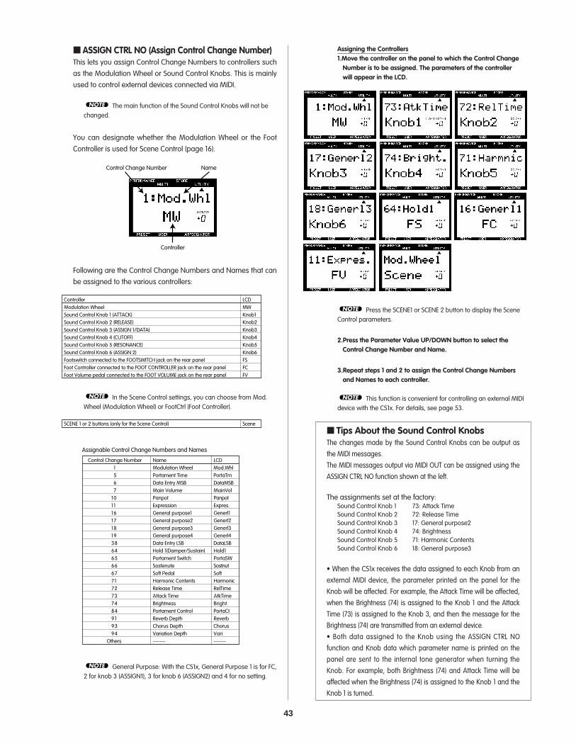
43
ASSIGN CTRL NO (Assign Control Change Number)This lets you assign Control Change Numbers to controllers suchas the Modulation Wheel or Sound Control Knobs. This is mainlyused to control external devices connected via MIDI.
The main function of the Sound Control Knobs will not bechanged.
You can designate whether the Modulation Wheel or the FootController is used for Scene Control (page 16).
Following are the Control Change Numbers and Names that canbe assigned to the various controllers:
In the Scene Control settings, you can choose from Mod.Wheel (Modulation Wheel) or FootCtrl (Foot Controller).
General Purpose: With the CS1x, General Purpose 1 is for FC,2 for knob 3 (ASSIGN1), 3 for knob 6 (ASSIGN2) and 4 for no setting.
NOTE
Control Change Number Name LCD1 Modulation Wheel Mod.Whl5 Portament Time PortaTm6 Data Entry MSB DataMSB7 Main Volume MainVol
10 Panpot Panpot11 Expression Expres.16 General purpose1 Generl117 General purpose2 Generl218 General purpose3 Generl319 General purpose4 Generl438 Data Entry LSB DataLSB64 Hold 1(Damper/Sustain) Hold165 Portament Switch PortaSW66 Sostenute Sostnut67 Soft Pedal Soft71 Harmonic Contents Harmonic72 Release Time RelTime73 Attack Time AtkTime74 Brightness Bright.84 Portament Control PortaCt91 Reverb Depth Reverb93 Chorus Depth Chorus94 Variation Depth Vari
Others ------- -------
Assignable Control Change Numbers and Names
SceneSCENE 1 or 2 buttons (only for the Scene Control)
NOTE
Controller LCDModulation Wheel MWSound Control Knob 1 (ATTACK) Knob1Sound Control Knob 2 (RELEASE) Knob2Sound Control Knob 3 (ASSIGN 1/DATA) Knob3Sound Control Knob 4 (CUTOFF) Knob4Sound Control Knob 5 (RESONANCE) Knob5Sound Control Knob 6 (ASSIGN 2) Knob6Footswitch connected to the FOOTSWITCH jack on the rear panel FSFoot Controller connected to the FOOT CONTROLLER jack on the rear panel FCFoot Volume pedal connected to the FOOT VOLUME jack on the rear panel FV
Control Change Number Name
Controller
NOTE
Assigning the Controllers1.Move the controller on the panel to which the Control Change
Number is to be assigned. The parameters of the controllerwill appear in the LCD.
Press the SCENE1 or SCENE 2 button to display the SceneControl parameters.
2.Press the Parameter Value UP/DOWN button to select theControl Change Number and Name.
3.Repeat steps 1 and 2 to assign the Control Change Numbersand Names to each controller.
This function is convenient for controlling an external MIDIdevice with the CS1x. For details, see page 53.
Tips About the Sound Control KnobsThe changes made by the Sound Control Knobs can be output asthe MIDI messages.The MIDI messages output via MIDI OUT can be assigned using theASSIGN CTRL NO function shown at the left.
The assignments set at the factory:Sound Control Knob 1 73: Attack TimeSound Control Knob 2 72: Release TimeSound Control Knob 3 17: General purpose2Sound Control Knob 4 74: BrightnessSound Control Knob 5 71: Harmonic ContentsSound Control Knob 6 18: General purpose3
• When the CS1x receives the data assigned to each Knob from anexternal MIDI device, the parameter printed on the panel for theKnob will be affected. For example, the Attack Time will be affected,when the Brightness (74) is assigned to the Knob 1 and the AttackTime (73) is assigned to the Knob 3, and then the message for theBrightness (74) are transmitted from an external device.• Both data assigned to the Knob using the ASSIGN CTRL NOfunction and Knob data which parameter name is printed on thepanel are sent to the internal tone generator when turning theKnob. For example, both Brightness (74) and Attack Time will beaffected when the Brightness (74) is assigned to the Knob 1 and theKnob 1 is turned.
NOTE
NOTE

44
3. Press the ENTER/YES button. “Sure?” will appear in the LCD.
To audition the sound, simply play the keyboard.
4. Press the YES/ENTER button again to execute the storingoperation. The display will return to the Performance Playmode screen after the data is stored.
Press the NO button to cancel the storing operation.
Pressing the PERFORMANCE button exits Store mode.
When storing a Performace, the position of each Sound Control Knob willalso be stored. Therefore, when selecting the stored User Performance inPerformance Play mode, the CS1x will produce the sound affected byeach Sound Control Knob position at that time. (Turning the Knob willrestore the sound with the current Sound Control Knob positions.)
Storing a SceneThere are two "Scene" memories dedicated to eachPerformance. This function is used to assign a Scene, or theposition of the six Sound Control Knobs, to the SCENE 1 orSCENE 2 button. This is convenient for live performances orrecording sessions, since it lets you access a particular settingsimply by pressing a button.
Two Scenes can be stored in each Performance.
Once you have stored a Scene to the edit buffer (temporarysave), to store the Scene data permanently you must perform thePerformance store operation, above. (Before executing the PerformanceStore operation to record the Scene as a part of the performance, turn allthe sound control knobs to their center positions.) Otherwise, you will losethe Scene settings if you select another Performance or enter Multi Playmode.
NOTE
NOTE
VWX
7
YZ'
8
&*
9MNO
4
PQR
5
STU
6DEF
1
GHI
2
JKL
NO/QUICK PC
YES
3ABC
0
SPACE
ENTER
You cannot enter Store mode from Multi Play mode orUtility mode.
Storing a Performance1. After editing a performance, press the STORE button to enter
Store mode.
2. Select the User Performance number in which you want tostore the Performance, using the numeric keypad (0~9),PROGRAM [-]/[+] buttons, or Data Entry knob.
If you write over an existing User Performance, the datapreviously stored there will be lost. To be safe, always store yourimportant data to an external device such as the Yamaha MIDI DataFiler MDF2. If you want, you can reset the User Performances back tothe original factory settings. For details, see Factory Settings, page 46.
To rename the Performance, select the Performance Nameparameter in Performance Edit mode (see page 24).
NOTE
ERFORMANCE MULTI
DEMO
STORE UTILITY
Preset Performance1~128
PERFORMANCE STORE
User Performance1~128
Edited PerformanceStore Destination
STORE
SCENE STORE
Scene 1Memory
6 Knob Position Scene 1/2
NOTE
In Store mode you can store edited Performances or Scenes in the CS1x's internal memory. To enter Store Mode, you must first be in Performance Mode.
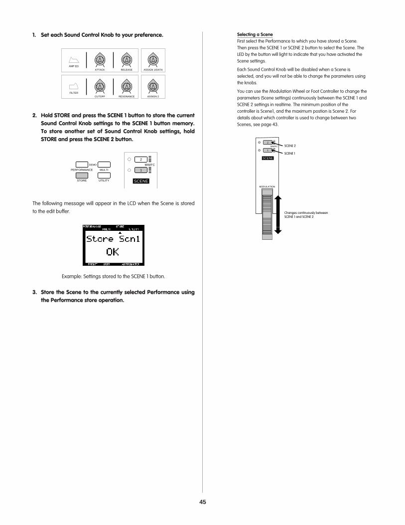
45
1. Set each Sound Control Knob to your preference.
2. Hold STORE and press the SCENE 1 button to store the currentSound Control Knob settings to the SCENE 1 button memory.To store another set of Sound Control Knob settings, holdSTORE and press the SCENE 2 button.
The following message will appear in the LCD when the Scene is storedto the edit buffer.
Example: Settings stored to the SCENE 1 button.
3. Store the Scene to the currently selected Performance usingthe Performance store operation.
PERFORMANCE MULTI
DEMO
STORE UTILITY
2
MW/FC
1
SCENE
ATTACKAMP EG
RELEASE ASSIGN 1/DATA
CUTOFFFILTER
RESONANCE ASSIGN 2
Selecting a SceneFirst select the Performance to which you have stored a Scene.Then press the SCENE 1 or SCENE 2 button to select the Scene. TheLED by the button will light to indicate that you have activated theScene settings.
Each Sound Control Knob will be disabled when a Scene isselected, and you will not be able to change the parameters usingthe knobs.
You can use the Modulation Wheel or Foot Controller to change theparameters (Scene settings) continuously between the SCENE 1 andSCENE 2 settings in realtime. The minimum position of thecontroller is Scene1, and the maximum postion is Scene 2. Fordetails about which controller is used to change between twoScenes, see page 43.
2
MW/FC
1
SCENE
MODULATION
SCENE 2
SCENE 1
Changes continuously betweenSCENE 1 and SCENE 2
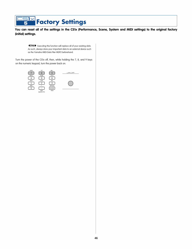
46
Executing this function will replace all of your existing data.As such, always store your important data to an external device suchas the Yamaha MIDI Data Filer MDF2 beforehand.
Turn the power of the CS1x off, then, while holding the 7, 8, and 9 keyson the numeric keypad, turn the power back on.
VWX
7
YZ'
8
&*
9MNO
4
PQR
5
STU
6DEF
1
GHI
2
JKL
NO/QUICK PC
YES
3ABC
0
SPACE
ENTER
ON OFF
NOTE
You can reset all of the settings in the CS1x (Performance, Scene, System and MIDI settings) to the original factory (initial) settings.

47
Type 1: ReverbReverb recreates the sounds of various environments by adding roomambiance through delays or reflections. There are 11 Reverb types tochoose from. (See page 49.)
Type 2: ChorusChorus creates a variety of rich, spacious-sounding effects which areespecially dramatic in stereo. There are 11 Chorus effect types, includingChorus and Flanger. (See page 49.)
Type 3: VariationVariation is a special section of various effects including Reverb andChorus, plus many others not found in the other sections, such asDistortion, Wah, and Auto Pan. There are 43 Variation effect types. (Seepage 49.)
System and Insertion EffectsThe CS1x effects sections can be designated as either System or Insertioneffects. Reverb and Chorus are always System effects, which means theycan be applied to any or all Parts. The Variation effect can also be aSystem effect, or it can be designated as an Insertion effect, which meansit can be dedicated to a specific Part.
Basically, CS1x System and Insertion effects work the same way as in asound mixer, as shown in the diagram at right. For example, Systemeffects can be applied to musical instruments (i.e., Parts) which areconnected to the various mixer channels; the amount of each Systemeffect is determined by channel "send" and system "return" level controls.An Insertion effect can be connected ("inserted") into the signal flow of aspecific channel in order to process the sound of that instrument (i.e.,Layer/Part) only.
With the CS1x, in Performance mode the Insertion effect (Variation) can beapplied to one or more of the four Layers, while in Multi Play mode it canonly be applied to a single Part.
The System and Insertion effect configurations can be controlled in detailby XG song data (signified by the XG mark) when the CS1x is in Multi Playmode.
Performance ModeThe diagram below shows the signal flow of the three effects when theCS1x is in Performance mode. In this case the Variation effect is fixed asthe Insertion effect.
The Variation Send On/Off switch ! determines which Layers theVariation effect is applied to. The Performance Layer Edit 4 menu EFFECTVARI SEND parameter turns the Variation effect ON/OFF for each Layer(see page 34).
The Variation effect wet/dry balance " determines the ratio of effected(wet) signal to original (dry) signal. The resulting Variation effect signal is
then sent to the Reverb effect via the Reverb send control #, and to the
Chorus effect via the Chorus send control $; the Send Chorus To Reverb
signal % can be controlled by the ASSIGN 1 knob. The Performance Layer
Edit 4 menu EFFECT REV SEND & and CHO SEND ' parameters determinethe respective Reverb and Chorus send levels applied to each Layer (see
page 34). Layers which are switched off !, as well as Parts 5~16, can stillhave System Reverb and Chorus effects applied to them.
100LEVEL
100LEVEL
100LEVEL
100LEVEL
100LEVEL
100LEVEL
100LEVEL
100LEVEL
100LEVEL
100LEVEL
100LEVEL
100LEVEL
100LEVEL
100LEVEL
100LEVEL
100LEVEL
100LEVEL
100LEVEL
100LEVEL
100LEVEL
100LEVEL
100LEVEL
100LEVEL
100LEVEL
100LEVEL
100LEVEL
100LEVEL
100LEVEL
100LEVEL
100LEVEL
100LEVEL
100LEVEL
100LEVEL
100LEVEL
100LEVEL
100LEVEL
100LEVEL
100LEVEL
100LEVEL
100LEVEL
100LEVEL
100LEVEL
L4
100LEVEL
100LEVEL
100LEVEL
100LEVEL
100LEVEL
100LEVEL
14 151 2 L116 L3L2
Multi Play ModePart 1-16
Performance ModeLayer 1-4
SYSTEM EFFECT
Reverb Effect
Chorus Effect
Variation EffectCan be used as either System or Insertion effect.
100LEVEL
100LEVEL
100LEVEL
100LEVEL
100LEVEL
100LEVEL
Insertion Effect Insertion Effect
The CS1x features three independent digital effects units, Reverb, Chorus and Variation, which can be applied to the voices in a variety of ways to provide a wide range of sound processing capabilities. In Performance mode you can choose the Reverb, Chorus and Variation effect types, as well as set additional parameters for the Variation effect. In Multi Play mode, system exclusive (MIDI) data programmed in a song sequence (of an external sequencer or computer) can change the various CS1x effect parameters at specific points in the song to greatly enhance the sound and impact of the playback.

48
The diagram below shows the signal flow of the three effects when theCS1x is in Multi Play mode and the Variation effect is designated as aSystem effect.
Each of the 16 Parts has a Dry send ! level which controls the amount of
original signal for each Part (page 38). Reverb send ", Chorus send #,
and Variation send $ levels control the amount of effect applied to eachPart, determined by the Multi Edit EFFECT REV SEND, CHO SEND and VARISEND parameters (between 0~127), respectively (page 38). Reverb return
%, Chorus return & and Variation return ' levels can also be controlledto determine the amount of each effect applied (page 38).
The Send Chorus to Reverb ( level is sent from the Chorus effect to the
Reverb effect (page 38). The Send Variation to Reverb ) and Send
Variation to Chorus * levels are sent from the Variation effect to theReverb and Chorus effects, respectively (page 38). These threeparameters let you make series and parallel effect configurations whichprovide enormous sound enhancement flexibility.
If you select Effect Off in the Variation Type menu, theLayers which have the VARI SEND function set to ON will not sound.When you don't want to use the Variation Effect on the Layers, set theVARI TYPE to Thru.
NOTE
Part 1
Part 2
Part 16
Rev
Cho
Vari
Rev Return Level
Cho Return
Vari Return
Vari to Rev
Vari to Cho
Cho to RevDry Send
Rev Send Cho Send Vari Send
Vari Send, Cho Send, Rev Send = 0~127
•XG effect set to System
Out
!
" # $
%
&
'
(
)
*
Part 1
Part 2
Part 3
Part 16
wet/dry
MULTI
Send Cho to Rev
Rev Return Level
Cho Return Level
Cho SendRev Send
Rev
•XG effect set to Insertion•Part 3 VARI SEND set to ON
Cho
OutVari
" #
%
&
$
!
Reverb and Chorus send levels for Layers with the VariationSend On/Off switch set to ON are determined by the highestnumbered Layer. For example, if Layers 1, 2 and 3 are switched on,then the Reverb and Chorus send level for Layer 3 will determine theamount of effect applied to each Layer.
In Performance mode effect send levels for Parts 5~16 (aswell as Layers 1~4) can be controlled by an external MIDI sequencer.The Variation effect cannot be applied to Parts 5~16.
Multi Play ModeThe diagram below shows the signal flow of the three effects when theCS1x is in Multi Play mode and the Variation effect is designated as anInsertion effect.
In Multi Play mode the various effect settings can becontrolled by MIDI system exclusive Parameter Change messages(received from an external sequencer or computer). The illustrations atright show the Reverb, Chorus and Variation send parameters whichcan be controlled from the CS1x panel. For details about the others,refer to each page number as listed in the following explanation.
When the CS1x is in Multi Play mode, the Variation Effect isautomatically reset as an Insertion Effect. If you want to set theVariation Effect as a System Effect, you need to send a parameterchange message to the CS1x from an external MIDI sequencer.
The Variation (Insertion) effect can be applied to any one of the 16 Parts ata time, designated by switching the Multi Edit EFFECT VARI SENDparameter to ON (page 38). The ratio of Variation effect (wet) signal to
original (dry) signal is determined by the wet/dry balance !, which inturn controls the amount of Variation effect signal applied to the Part(page 38).
Although only one Part at a time can have the Variation effect applied toit, all Parts, including the Part with Variation effect, can have Reverb and
Chorus applied, determined by the Reverb send " and Chorus send #level settings (between 0~127) of the Multi Edit EFFECT REV SEND and CHO
SEND parameters, respectively (page 38). Reverb return $ and Chorus
return % levels can also be controlled to determine the amount of each
effect applied. The Send Chorus to Reverb & level from the Chorus effectto the Reverb effect can also be controlled in a series, if you assign it to
the ASSIGN 1 knob (page 26); in this case, the Chorus return % levelshould be set to "0".
NOTE
NOTE
NOTE
NOTE
Layer 1on
PERFORMANCE
Layer 2on
Layer 3on
Layer 4off
wet/dry
Part 5
Part 16
Cho
Rev
Cho Send
Cho Send
Rev Send
Rev Send
OutKnobl (Cho to Rev)
(for each layer/part)
(for each layer/part)
!
!
!
!
"
#
$
%
&
'
Vari
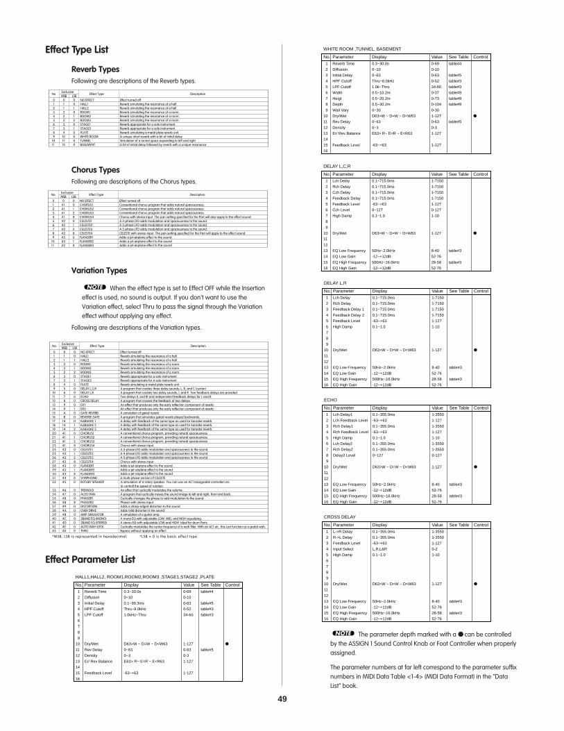
49
Effect Type List
Reverb TypesFollowing are descriptions of the Reverb types.
Chorus TypesFollowing are descriptions of the Chorus types.
Variation Types
When the effect type is set to Effect OFF while the Insertioneffect is used, no sound is output. If you don't want to use theVariation effect, select Thru to pass the signal through the Variationeffect without applying any effect.
Following are descriptions of the Variation types.
Effect Parameter List
No. Parameter Display Value See Table Control
HALL1,HALL2, ROOM1,ROOM2,ROOM3 ,STAGE1,STAGE2 ,PLATE
1 Reverb Time 0.3~30.0s 0-69 table#4
2 Diffusion 0~10 0-10
3 Initial Delay 0.1~99.3ms 0-63 table#5
4 HPF Cutoff Thru~8.0kHz 0-52 table#3
5 LPF Cutoff 1.0kHz~Thru 34-60 table#3
6
7
8
9
10 Dry/Wet D63>W ~ D=W ~ D<W63 1-127
11 Rev Delay 0~63 0-63 table#5
12 Density 0~3 0-3
13 Er/ Rev Balance E63> R~ E=R ~ E<R63 1-127
14
15 Feedback Level -63~+63 1-127
16
No.Exclusive
Effect Type DescriptionMSB LSB
0 0 0 NO EFFECT Effect turned off.1 1 0 HALL1 Reverb simulating the resonance of a hall.
Reverb simulating the resonance of a hall.2 1 1 HALL23 2 0 ROOM1 Reverb simulating the resonance of a room.
Reverb simulating the resonance of a room.Reverb simulating the resonance of a room.
4 2 1 ROOM25 2 2 ROOM36 3 0 STAGE1 Reverb approproate for a solo instrument.
Reverb approproate for a solo instrument.7 3 1 STAGE28 4 0 PLATE Reverb simulating a metal plate reverb unit.9 5 0 DELAY L,C,R A program that creates three delay sounds; L, R, and C (center).
10 6 0 DELAY L,R A program that creates two delay sounds; L and R. Two feedback delays are provided.11 7 0 ECHO Two delays (L and R) and independent feedback delays for L and R.12 8 0 CROSS DELAY A program that crosses the feedback of two delays.13 9 0 ER1 An effect that produces only the early reflection component of reverb.
An effect that produces only the early reflection component of reverb.14 9 1 ER215 A 0 GATE REVERB A simulation of gated reverb.16 B 0 REVERSE GATE A program that simulates gated reverb played backwords.17 14 0 KARAOKE 1 A delay with feedback of the same type as used for karaoke reverb.
A delay with feedback of the same type as used for karaoke reverb.A delay with feedback of the same type as used for karaoke reverb.
18 14 1 KARAOKE 219 14 2 KARAOKE 320 41 0 CHORUS1 A conventional chorus program, providing natural spaciousness.
A conventional chorus program, providing natural spaciousness.A conventional chorus program, providing natural spaciousness.
21 41 1 CHORUS222 41 2 CHORUS323 41 8 CHORUS4 Chorus with stereo input.24 42 0 CELESTE1 A 3-phase LFO adds modulation and spaciousness to the sound.
A 4-phase LFO adds modulation and spaciousness to the sound.A 5-phase LFO adds modulation and spaciousness to the sound.
25 42 1 CELESTE226 42 2 CELESTE327 42 8 CELESTE4 Chorus with stereo input.28 43 0 FLANGER1 Adds a jet-airplane effect to the sound.
Adds a jet-airplane effect to the sound.Adds a jet-airplane effect to the sound.
29 43 1 FLANGER230 43 8 FLANGER331 44 0 SYMPHONIC A multi-phase version of CELESTE.32 45 0 ROTARY SPEAKER A simulation of a rotary speaker. You can use an AC1 (assignable controller) etc.
to controll the speed of rotation.33 46 0 TREMOLO An effect that cyclically modulates the volume.34 47 0 AUTO PAN A program that cyclically moves the sound image to left and right, front and back.35 48 0 PHASER1 Cyclically changes the phase to add modulation to the sound.36 48 8 PHASER2 Phaser with stereo input.37 49 0 DISTORTION Adds a sharp-edged distortion to the sound.38 4A 0 OVER DRIVE Adds mild distortion ti the sound.39 4B 0 AMP SIMULATOR A simulation of a guitar amp.40 4C 0 3BAND EQ (MONO) A mono EQ with adjustable LOW, MID, and HIGH equalizing.41 4D 0 2BAND EQ (STEREO) A stereo EQ with adjustable LOW and HIGH. Ideal for drum Parts.42 4E 0 AUTO WAH (LFO) Cyclically modulates the center frequency of a wah filter. With an AC1 etc. this can function as a pedal wah.43
*MSB, LSB is represented in hexadecimal. *LSB = 0 is the basic effect type.
40 0 THRU Bypass without applying an effect.
NOTE
No.Exclusive
Effect Type DescriptionMSB LSB
0 0 0 NO EFFECT Effect turned off.1 41 0 CHORUS1 Conventional chorus program that adds natural spaciousness.
Conventional chorus program that adds natural spaciousness.Conventional chorus program that adds natural spaciousness.
2 41 1 CHORUS23 41 2 CHORUS34 41 8 CHORUS4 Chorus with stereo input. The pan setting specified for the Part will also apply to the effect sound.5 42 0 CELESTE1 A 3-phase LFO adds modulation and spaciousness to the sound.
A 3-phase LFO adds modulation and spaciousness to the sound.A 3-phase LFO adds modulation and spaciousness to the sound.
6 42 1 CELESTE27 42 2 CELESTE38 42 8 CELESTE4 CELESTE with stereo input. The pan setting specified for the Part will apply to the effect sound.9 43 0 FLANGER1 Adds a jet-airplane effect to the sound.
Adds a jet-airplane effect to the sound.Adds a jet-airplane effect to the sound.
10 43 1 FLANGER211 42 8 FLANGER3
No.Exclusive
Effect Type DescriptionMSB LSB
0 0 0 NO EFFECT Effect turned off.1 1 0 HALL1 Reverb simulating the resonance of a hall.
Reverb simulating the resonance of a hall.2 1 1 HALL23 2 0 ROOM1 Reverb simulating the resonance of a room.
Reverb simulating the resonance of a room.Reverb simulating the resonance of a room.
4 2 1 ROOM25 2 2 ROOM36 3 0 STAGE1 Reverb appropriate for a solo instrument.
Reverb appropriate for a solo instrument.7 3 1 STAGE28 4 0 PLATE Reverb simulating a metal plate reverb unit.9 10 0 WHITE ROOM A unique short reverb with a bit of initial delay.
10 11 0 TUNNEL Simulation of a tunnel space expanding to left and right.11 13 0 BASEMENT A bit of initial delay followed by reverb with a unique resonance.
The parameter depth marked with a can be controlledby the ASSIGN 1 Sound Control Knob or Foot Controller when properlyassigned.
The parameter numbers at far left correspond to the parameter suffixnumbers in MIDI Data Table <1-4> (MIDI Data Format) in the "DataList" book.
NOTE
1 L->R Delay 0.1~355.0ms 1-3550
2 R->L Delay 0.1~355.0ms 1-3550
3 Feedback Level -63~+63 1-127
4 Input Select L,R,L&R 0-2
5 High Damp 0.1~1.0 1-10
6
7
8
9
10 Dry/Wet D63>W ~ D=W ~ D<W63 1-127
11
12
13 EQ Low Frequency 50Hz~2.0kHz 8-40 table#3
14 EQ Low Gain -12~+12dB 52-76
15 EQ High Frequency 500Hz~16.0kHz 28-58 table#3
16 EQ High Gain -12~+12dB 52-76
No. Parameter Display Value See Table Control
CROSS DELAY
1 Lch Delay1 0.1~355.0ms 1-3550
2 Lch Feedback Level -63~+63 1-127
3 Rch Delay1 0.1~355.0ms 1-3550
4 Rch Feedback Level -63~+63 1-127
5 High Damp 0.1~1.0 1-10
6 Lch Delay2 0.1~355.0ms 1-3550
7 Rch Delay2 0.1~355.0ms 1-3550
8 Delay2 Level 0~127 0-127
9
10 Dry/Wet D63>W ~ D=W ~ D<W63 1-127
11
12
13 EQ Low Frequency 50Hz~2.0kHz 8-40 table#3
14 EQ Low Gain -12~+12dB 52-76
15 EQ High Frequency 500Hz~16.0kHz 28-58 table#3
16 EQ High Gain -12~+12dB 52-76
No. Parameter Display Value See Table Control
ECHO
1 Lch Delay 0.1~715.0ms 1-7150
2 Rch Delay 0.1~715.0ms 1-7150
3 Feedback Delay 1 0.1~715.0ms 1-7150
4 Feedback Delay 2 0.1~715.0ms 1-7150
5 Feedback Level -63~+63 1-127
6 High Damp 0.1~1.0 1-10
7
8
9
10 Dry/Wet D63>W ~ D=W ~ D<W63 1-127
11
12
13 EQ Low Frequency 50Hz~2.0kHz 8-40 table#3
14 EQ Low Gain -12~+12dB 52-76
15 EQ High Frequency 500Hz~16.0kHz 28-58 table#3
16 EQ High Gain -12~+12dB 52-76
No. Parameter Display Value See Table Control
DELAY L,R
1 Lch Delay 0.1~715.0ms 1-7150
2 Rch Delay 0.1~715.0ms 1-7150
3 Cch Delay 0.1~715.0ms 1-7150
4 Feedback Delay 0.1~715.0ms 1-7150
5 Feedback Level -63~+63 1-127
6 Cch Level 0~127 0-127
7 High Damp 0.1~1.0 1-10
8
9
10 Dry/Wet D63>W ~ D=W ~ D<W63 1-127
11
12
13 EQ Low Frequency 50Hz~2.0kHz 8-40 table#3
14 EQ Low Gain -12~+12dB 52-76
15 EQ High Frequency 500Hz~16.0kHz 28-58 table#3
16 EQ High Gain -12~+12dB 52-76
No. Parameter Display Value See Table Control
DELAY L,C,R
1 Reverb Time 0.3~30.0s 0-69 table#4
2 Diffusion 0~10 0-10
3 Initial Delay 0~63 0-63 table#5
4 HPF Cutoff Thru~8.0kHz 0-52 table#3
5 LPF Cutoff 1.0k~Thru 34-60 table#3
6 Width 0.5~10.2m 0-37 table#8
7 Heigt 0.5~20.2m 0-73 table#8
8 Depth 0.5~30.2m 0-104 table#8
9 Wall Vary 0~30 0-30
10 Dry/Wet D63>W ~ D=W ~ D<W63 1-127
11 Rev Delay 0~63 0-63 table#5
12 Density 0~3 0-3
13 Er/ Rev Balance E63> R~ E=R ~ E<R63 1-127
14
15 Feedback Level -63~+63 1-127
16
No. Parameter Display Value See Table Control
WHITE ROOM ,TUNNEL, BASEMENT

50
The parameter depth marked with a can be controlledby the ASSIGN 1 Sound Control Knob or Foot Controller when properlyassigned.
The parameter numbers at far left correspond to the parameter suffixnumbers in MIDI Data Table <1-4> (MIDI Data Format) in the "DataList" book.
NOTE
1 LFO Frequency 0.00~39.7Hz 0-127 table#1
2 LFO Depth 0~127 0-127
3 Phase Shift Offset 0~127 0-127
4 Feedback Level -63~+63 1-127
5
6 EQ Low Frequency 50Hz~2.0kHz 8-40 table#3
7 EQ Low Gain -12~+12dB 52-76
8 EQ High Frequency 500Hz~16.0kHz 28-58 table#3
9 EQ High Gain -12~+12dB 52-76
10 Dry/Wet D63>W ~ D=W ~ D<W63 1-127
11 Stage 6~10(phaser1) / 3~5(phaser2) 3-10
12 Diffusion Mono/Stereo 0-1
13 LFO Phase Difference -180~+180deg. 4-124 Phaser2
14
15
16
No. Parameter Display Value See Table Control
PHASER1, PHASER2
1 LFO Frequency 0.00~39.7Hz 0-127 table#1
2 L/R Depth 0~127 0-127
3 F/R Depth 0~127 0-127
4 PAN Direction L<->R,L->R,L<-R,Lturn,Rturn,L/R 0-5
5
6 EQ Low Frequency 50Hz~2.0kHz 8-40 table#3
7 EQ Low Gain -12~+12dB 52-76
8 EQ High Frequency 500Hz~16.0kHz 28-58 table#3
9 EQ High Gain -12~+12dB 52-76
10
11
12
13
14
15
16
No. Parameter Display Value See Table Control
AUTO PAN
1 LFO Frequency 0.00~39.7Hz 0-127 table#1
2 AM Depth 0~127 0-127
3 PM Depth 0~127 0-127
4
5
6 EQ Low Frequency 50Hz~2.0kHz 8-40 table#3
7 EQ Low Gain -12~+12dB 52-76
8 EQ High Frequency 500Hz~16.0kHz 28-58 table#3
9 EQ High Gain -12~+12dB 52-76
10
11
12
13
14 LFO Phase Difference -180~+180deg 4-124 resolution=3deg.
15 Input Mode mono/stereo 0-1
16
No. Parameter Display Value See Table Control
TREMOLO
1 LFO Frequency 0.00~39.7Hz 0-127 table#1
2 LFO Depth 0~127 0-127
3
4
5
6 EQ Low Frequency 50Hz~2.0kHz 8-40 table#3
7 EQ Low Gain -12~+12dB 52-76
8 EQ High Frequency 500Hz~16.0kHz 28-58 table#3
9 EQ High Gain -12~+12dB 52-76
10 Dry/Wet D63>W ~ D=W ~ D<W63 1-127
11
12
13
14
15
16
No. Parameter Display Value See Table Control
ROTARY SPEAKER
1 LFO Frequency 0.00~39.7Hz 0-127 table#1
2 LFO Depth 0~127 0-127
3 Delay Offset 0.0~50.0ms 0-127 table#2
4
5
6 EQ Low Frequency 50Hz~2.0kHz 8-40 table#3
7 EQ Low Gain -12~+12dB 52-76
8 EQ High Frequency 500Hz~16.0kHz 28-58 table#3
9 EQ High Gain -12~+12dB 52-76
10 Dry/Wet D63>W ~ D=W ~ D<W63 1-127
11
12
13
14
15
16
No. Parameter Display Value See Table Control
SYMPHONIC
1 LFO Frequency 0.00~39.7Hz 0-127 table#1
2 LFO Depth 0~127 0-127
3 Feedback Level -63~+63 1-127
4 Delay Offset 0.0~6.3ms 0-63 table#2
5
6 EQ Low Frequency 50Hz~2.0kHz 8-40 table#3
7 EQ Low Gain -12~+12dB 52-76
8 EQ High Frequency 500Hz~16.0kHz 28-58 table#3
9 EQ High Gain -12~+12dB 52-76
10 Dry/Wet D63>W ~ D=W ~ D<W63 1-127
11
12
13
14 LFO Phase Difference -180~+180deg 4-124 resolution=3deg.
15
16
No. Parameter Display Value See Table Control
FLANGER1,FLANGER2,FLANGER3
1 LFO Frequency 0.00~39.7Hz 0-127 table#1
2 LFO PM Depth 0~127 0-127
3 Feedback Level -63~+63 1-127
4 Delay Offset 0.0~50.0ms 0-127 table#2
5
6 EQ Low Frequency 50Hz~2.0kHz 8-40 table#3
7 EQ Low Gain -12~+12dB 52-76
8 EQ High Frequency 500Hz~16.0kHz 28-58 table#3
9 EQ High Gain -12~+12dB 52-76
10 Dry/Wet D63>W ~ D=W ~ D<W63 1-127
11
12
13
14
15 Input Mode mono/stereo 0-1
16
No. Parameter Display Value See Table Control
CHORUS1,2,3,4, CELESTE1,2,3,4
1 Delay Time 0~400.0ms 0-127 table#7
2 Feedback Level -63~+63 1-127
3 HPF Cutoff Thru~8.0kHz 0-52
4 LPF Cutoff 1.0k~Thru 34-60
5
6
7
8
9
10 Dry/Wet D63>W ~ D=W ~ D<W63 1-127
11
12
13
14
15
16
No. Parameter Display Value See Table Control
KARAOKE1,2,3
1 Type TypeA,TypeB 0-1
2 Room Size 0.1~7.0 0-44 table#6
3 Diffusion 0~10 0-10
4 Initial Delay 0.1~99.3ms 0-63 table#5
5 Feedback Level -63~+63 1-127
6 HPF Cutoff Thru~8.0kHz 0-52
7 LPF Cutoff 1.0k~Thru 34-60
8
9
10 Dry/Wet D63>W ~ D=W ~ D<W63 1-127
11 Liveness 0~10 0-10
12 Density 0~3 0-3
13 High Damp 0.1~1.0 1-10
14
15
16
No. Parameter Display Value See Table Control
GATE REVERB,REVERSE GATE
1 Type S-H, L-H, Rdm, Rvs, Plt, Spr 0-5
2 Room Size 0.1~7.0 0-44 table#6
3 Diffusion 0~10 0-10
4 Initial Delay 0.1~99.3ms 0-63 table#5
5 Feedback Level -63~+63 1-127
6 HPF Cutoff Thru~8.0kHz 0-52
7 LPF Cutoff 1.0k~Thru 34-60
8
9
10 Dry/Wet D63>W ~ D=W ~ D<W63 1-127
11 Liveness 0~10 0-10
12 Density 0~3 0-3
13 High Damp 0.1~1.0 1-10
14
15
16
No. Parameter Display Value See Table Control
EARLY REF1,EARLY REF2

51
The parameter depth marked with a can be controlledby the ASSIGN 1 Sound Control Knob or Foot Controller when properlyassigned.
The parameter numbers at far left correspond to the parameter suffixnumbers in MIDI Data Table <1-4> (MIDI Data Format) in the "DataList" book.
NOTE
1 LFO Frequency 0.00~39.7Hz 0-127 table#1
2 LFO Depth 0~127 0-127
3 Cutoff Frequency Offset 50Hz~14.0kHz 0-127 table#9
4 Resonance 1.0~12.0 10-120
5
6 EQ Low Frequency 50Hz~2.0kHz 8-40 table#3
7 EQ Low Gain -12~+12dB 52-76
8 EQ High Frequency 500Hz~16.0kHz 28-58 table#3
9 EQ High Gain -12~+12dB 52-76
10 Dry/Wet D63>W ~ D=W ~ D<W63 1-127
11
12
13
14
15
16
No. Parameter Display Value See Table Control
AUTO WAH
1 EQ Low Frequency 50Hz~2.0kHz 8-40 table#3
2 EQ Low Gain -12~+12dB 52-76
3 EQ High Frequency 500Hz~16.0kHz 28-58 table#3
4 EQ High Gain -12~+12dB 52-76
5
6
7
8
9
10
11
12
13
14
15
16
No. Parameter Display Value See Table Control
STEREO EQ(2-BAND)
1 EQ Low Gain -12~+12dB 52-76
2 EQ Mid Frequency 500Hz~10.0kHz 28-54 table#3
3 EQ Mid Gain -12~+12dB 52-76
4 EQ Mid Width 1.0~12.0 10-120
5 EQ High Gain -12~+12dB 52-76
6 EQ Low Frequency 50Hz~2.0kHz 8-40 table#3
7 EQ High Frequency 500Hz~16.0kHz 28-58 table#3
8
9
10
11
12
13
14
15
16
No. Parameter Display Value See Table Control
MONO EQ(3-BAND)
1 Drive 0~127 0-127
2 AMP Type Off,Stack,Combo,Tube 0-3
3 LPF Cutoff 1.0k~Thru 34-60 table#3
4 Output Level 0~127 0-127
5
6
7
8
9
10 Dry/Wet D63>W ~ D=W ~ D<W63 1-127
11 Edge(Clip Curve) 0~127 0-127 mild~sharp
12
13
14
15
16
No. Parameter Display Value See Table Control
GUITAR AMP SIMULATOR
1 Drive 0~127 0-127
2 EQ Low Frequency 50Hz~2.0kHz 8-40 table#3
3 EQ Low Gain -12~+12dB 52-76
4 LPF Cutoff 1.0k~Thru 34-60 table#3
5 Output Level 0~127 0-127
6
7 EQ Mid Frequency 500Hz~10.0kHz 28-54 table#3
8 EQ Mid Gain -12~+12dB 52-76
9 EQ Mid Width 1.0~12.0 10-120
10 Dry/Wet D63>W ~ D=W ~ D<W63 1-127
11 Edge(Clip Curve) 0~127 0-127 mild~sharp
12
13
14
15
16
No. Parameter Display Value See Table Control
DISTORTION,OVERDRIVE Effect Data Assign Table
Data Value
EQ FrequencyTable#3
Data Value0 THRU(20)1 222 253 284 325 366 407 458 509 56
10 6311 7012 8013 9014 10015 11016 12517 14018 16019 18020 20021 22522 25023 28024 31525 35526 40027 45028 50029 56030 63031 700
32 80033 90034 1.0k35 1.1k36 1.2k37 1.4k38 1.6k39 1.8k40 2.0k41 2.2k42 2.5k43 2.8k44 3.2k45 3.6k46 4.0k47 4.5k48 5.0k49 5.6k50 6.3k51 7.0k52 8.0k53 9.0k54 10.0k55 11.0k56 12.0k57 14.0k58 16.0k59 18.0k60 THRU(20.0k)
Data Value
Modulation Delay OffsetTable#2
Data Value Data Value Data Value0 0.01 0.12 0.23 0.34 0.45 0.56 0.67 0.78 0.89 0.9
10 1.011 1.112 1.213 1.314 1.415 1.516 1.617 1.718 1.819 1.920 2.021 2.122 2.223 2.324 2.425 2.526 2.627 2.728 2.829 2.930 3.031 3.1
32 3.233 3.334 3.435 3.536 3.637 3.738 3.839 3.940 4.041 4.142 4.243 4.344 4.445 4.546 4.647 4.748 4.849 4.950 5.051 5.152 5.253 5.354 5.455 5.556 5.657 5.758 5.859 5.960 6.061 6.162 6.263 6.3
64 6.465 6.566 6.667 6.768 6.869 6.970 7.071 7.172 7.273 7.374 7.475 7.576 7.677 7.778 7.879 7.980 8.081 8.182 8.283 8.384 8.485 8.586 8.687 8.788 8.889 8.990 9.091 9.192 9.293 9.394 9.495 9.5
96 9.697 9.798 9.899 9.9
100 10.0101 11.1102 12.2103 13.3104 14.4105 15.5106 17.1107 18.6108 20.2109 21.8110 23.3111 24.9112 26.5113 28.0114 29.6115 31.2116 32.8117 34.3118 35.9119 37.5120 39.0121 40.6122 42.2123 43.7124 45.3125 46.9126 48.4127 50.0
Data Value
LFO FrequencyTable#1
Data Value Data Value Data Value0 0.001 0.042 0.083 0.134 0.175 0.216 0.257 0.298 0.349 0.38
10 0.4211 0.4612 0.5113 0.5514 0.5915 0.6316 0.6717 0.7218 0.7619 0.8020 0.8421 0.8822 0.9323 0.9724 1.0125 1.0526 1.0927 1.1428 1.1829 1.2230 1.2631 1.30
32 1.3533 1.3934 1.4335 1.4736 1.5137 1.5638 1.6039 1.6440 1.6841 1.7242 1.7743 1.8144 1.8545 1.8946 1.9447 1.9848 2.0249 2.0650 2.1051 2.1552 2.1953 2.2354 2.2755 2.3156 2.3657 2.4058 2.4459 2.4860 2.5261 2.5762 2.6163 2.65
64 2.6965 2.7866 2.8667 2.9468 3.0369 3.1170 3.2071 3.2872 3.3773 3.4574 3.5375 3.6276 3.7077 3.8778 4.0479 4.2180 4.3781 4.5482 4.7183 4.8884 5.0585 5.2286 5.3887 5.5588 5.7289 6.0690 6.3991 6.7392 7.0793 7.4094 7.7495 8.08
96 8.4197 8.7598 9.0899 9.42
100 9.76101 10.10102 10.80103 11.40104 12.10105 12.80106 13.50107 14.10108 14.80109 15.50110 16.20111 16.80112 17.50113 18.20114 19.50115 20.90116 22.20117 23.60118 24.90119 26.20120 27.60121 28.90122 30.30123 31.60124 33.00125 34.30126 37.00127 39.70
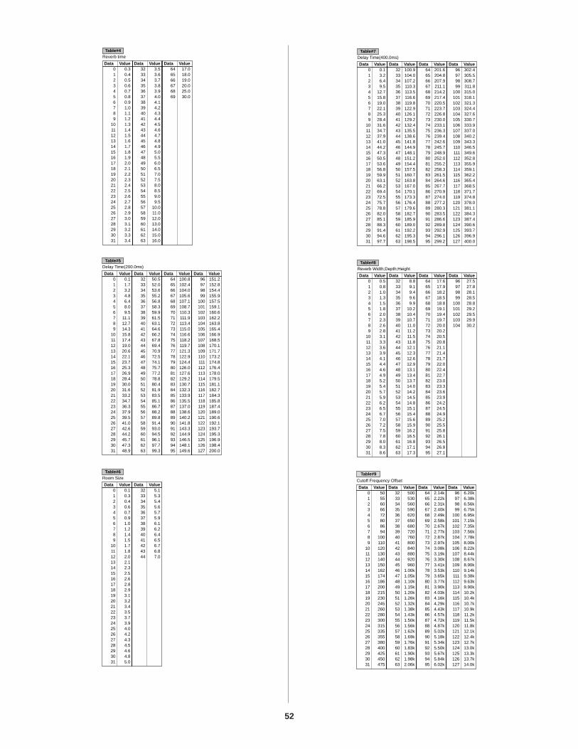
52
Cutoff Frequency Offset
Table#9
Data Value Data Value Data Value Data Value0 501 552 603 664 725 806 867 948 1009 110
10 12011 13012 14013 15014 16215 17416 18617 20018 21519 23020 24521 26022 28023 30024 31525 33526 35527 38028 40029 42530 45031 475
32 50033 53034 56035 59036 62037 65038 68039 72040 76041 80042 84043 88044 92045 96046 1.00k47 1.05k48 1.10k49 1.15k50 1.20k51 1.26k52 1.32k53 1.38k54 1.43k55 1.50k56 1.56k57 1.62k58 1.69k59 1.76k60 1.83k61 1.90k62 1.98k63 2.06k
64 2.14k65 2.22k66 2.31k67 2.40k68 2.49k69 2.58k70 2.67k71 2.77k72 2.87k73 2.97k74 3.08k75 3.19k76 3.30k77 3.41k78 3.53k79 3.65k80 3.77k81 3.90k82 4.03k83 4.16k84 4.29k85 4.43k86 4.57k87 4.72k88 4.87k89 5.02k90 5.18k91 5.34k92 5.50k93 5.67k94 5.84k95 6.02k
96 6.20k97 6.38k98 6.56k99 6.75k
100 6.95k101 7.15k102 7.35k103 7.56k104 7.78k105 8.00k106 8.22k107 8.44k108 8.67k109 8.90k110 9.14k111 9.38k112 9.63k113 9.90k114 10.2k115 10.4k116 10.7k117 10.9k118 11.2k119 11.5k120 11.8k121 12.1k122 12.4k123 12.7k124 13.0k125 13.3k126 13.7k127 14.0k
Data Value
Reverb Width;Depth;HeightTable#8
Data Value Data Value Data Value0 0.51 0.82 1.03 1.34 1.55 1.86 2.07 2.38 2.69 2.8
10 3.111 3.312 3.613 3.914 4.115 4.416 4.617 4.918 5.219 5.420 5.721 5.922 6.223 6.524 6.725 7.026 7.227 7.528 7.829 8.030 8.331 8.6
32 8.833 9.134 9.435 9.636 9.937 10.238 10.439 10.740 11.041 11.242 11.543 11.844 12.145 12.346 12.647 12.948 13.149 13.450 13.751 14.052 14.253 14.554 14.855 15.156 15.457 15.658 15.959 16.260 16.561 16.862 17.163 17.3
64 17.665 17.966 18.267 18.568 18.869 19.170 19.471 19.772 20.073 20.274 20.575 20.876 21.177 21.478 21.779 22.080 22.481 22.782 23.083 23.384 23.685 23.986 24.287 24.588 24.989 25.290 25.591 25.892 26.193 26.594 26.895 27.1
96 27.597 27.898 28.199 28.5
100 28.8101 29.2102 29.5103 29.9104 30.2
Data Value
Delay Time(400.0ms)Table#7
Data Value Data Value Data Value0 0.11 3.22 6.43 9.54 12.75 15.86 19.07 22.18 25.39 28.4
10 31.611 34.712 37.913 41.014 44.215 47.316 50.517 53.618 56.819 59.920 63.121 66.222 69.423 72.524 75.725 78.826 82.027 85.128 88.329 91.430 94.631 97.7
32 100.933 104.034 107.235 110.336 113.537 116.638 119.839 122.940 126.141 129.242 132.443 135.544 138.645 141.846 144.947 148.148 151.249 154.450 157.551 160.752 163.853 167.054 170.155 173.356 176.457 179.658 182.759 185.960 189.061 192.262 195.363 198.5
64 201.665 204.866 207.967 211.168 214.269 217.470 220.571 223.772 226.873 230.074 233.175 236.376 239.477 242.678 245.779 248.980 252.081 255.282 258.383 261.584 264.685 267.786 270.987 274.088 277.289 280.390 283.591 286.692 289.893 292.994 296.195 299.2
96 302.497 305.598 308.799 311.8
100 315.0101 318.1102 321.3103 324.4104 327.6105 330.7106 333.9107 337.0108 340.2109 343.3110 346.5111 349.6112 352.8113 355.9114 359.1115 362.2116 365.4117 368.5118 371.7119 374.8120 378.0121 381.1122 384.3123 387.4124 390.6125 393.7126 396.9127 400.0
Data Value
Room SizeTable#6
Data Value0 0.11 0.32 0.43 0.64 0.75 0.96 1.07 1.28 1.49 1.5
10 1.711 1.812 2.013 2.114 2.315 2.516 2.617 2.818 2.919 3.120 3.221 3.422 3.523 3.724 3.925 4.026 4.227 4.328 4.529 4.630 4.831 5.0
32 5.133 5.334 5.435 5.636 5.737 5.938 6.139 6.240 6.441 6.542 6.743 6.844 7.0
Data Value
Delay Time(200.0ms)Table#5
Data Value Data Value Data Value0 0.11 1.72 3.23 4.84 6.45 8.06 9.57 11.18 12.79 14.3
10 15.811 17.412 19.013 20.614 22.115 23.716 25.317 26.918 28.419 30.020 31.621 33.222 34.723 36.324 37.925 39.526 41.027 42.628 44.229 45.730 47.331 48.9
32 50.533 52.034 53.635 55.236 56.837 58.338 59.939 61.540 63.141 64.642 66.243 67.844 69.445 70.946 72.547 74.148 75.749 77.250 78.851 80.452 81.953 83.554 85.155 86.756 88.257 89.858 91.459 93.060 94.561 96.162 97.763 99.3
64 100.865 102.466 104.067 105.668 107.169 108.770 110.371 111.972 113.473 115.074 116.675 118.276 119.777 121.378 122.979 124.480 126.081 127.682 129.283 130.784 132.385 133.986 135.587 137.088 138.689 140.290 141.891 143.392 144.993 146.594 148.195 149.6
96 151.297 152.898 154.499 155.9
100 157.5101 159.1102 160.6103 162.2104 163.8105 165.4106 166.9107 168.5108 170.1109 171.7110 173.2111 174.8112 176.4113 178.0114 179.5115 181.1116 182.7117 184.3118 185.8119 187.4120 189.0121 190.6122 192.1123 193.7124 195.3125 196.9126 198.4127 200.0
Data Value
Reverb timeTable#4
Data Value Data Value0 0.31 0.42 0.53 0.64 0.75 0.86 0.97 1.08 1.19 1.2
10 1.311 1.412 1.513 1.614 1.715 1.816 1.917 2.018 2.119 2.220 2.321 2.422 2.523 2.624 2.725 2.826 2.927 3.028 3.129 3.230 3.331 3.4
32 3.533 3.634 3.735 3.836 3.937 4.038 4.139 4.240 4.341 4.442 4.543 4.644 4.745 4.846 4.947 5.048 5.549 6.050 6.551 7.052 7.553 8.054 8.555 9.056 9.557 10.058 11.059 12.060 13.061 14.062 15.063 16.0
64 17.065 18.066 19.067 20.068 25.069 30.0
MIDI Messages Transmitted/Received by the CS1xMIDI messages can be divided into two groups: Channel messages andSystem messages. Below is an explanation of the various types of MIDImessages which the CS1x can receive/transmit.
1. CHANNEL MESSAGESChannel messages are the data related to the performance on thekeyboard for the specific channel.
1.1 Note On/Note Off (Key On/Key Off)Messages which are generated when the keyboard is played.
Reception note range = C-2 (0) - G8 (127), C3 = 60
Velocity range = 1 - 127 (Only the Note On velocity is received)
Note On: Generated when a key is pressed.
Note Off: Generated when a key is released.
Each message includes a specific note number which corresponds to thekey which is pressed, plus a velocity value based on how hard the key isstruck.
1.2 Control ChangeControl Change messages let you select a voice bank, control volume,panning, modulation, portamento time, brightness and various othercontroller parameters, through specific Control Change numbers whichcorrespond to each of the various parameters.
1.2.1 Bank Select MSB (Control #000)Bank Select LSB (Control #032)
Messages which select variation voice bank numbers by combiningand sending the MSB and LSB from an external device.
MSB and LSB functions differently depending on the tone generatormode.
In XG mode, MSB numbers select voice type (Normal Voice or DrumVoice), and LSB numbers select voice banks.
In TG300B mode, LSB is fixed, and MSB numbers select voice banks.
(For more information about Banks and Programs, see Voice List inthe "Data List" book.)
A new bank selection will not become effective until the nextProgram Change message is received.
1.2.2 Modulation (Control #001)Messages which control vibrato depth using the Modulation Wheel.
Setting the value to 127 produces maximum vibrato and 0 results invibrato off.
1.2.3 Portamento Time (Control #005)Messages which control the duration of portamento, or a continuouspitch glide between successively played notes.
When the parameter 1.2.10 Portamento Switch is set to on, the valueset here can adjust the speed of pitch change.
Setting the value to 127 produces maximum portamento time and 0results in minimum portamento time.
1.2.4 Data Entry MSB (Control #006)Data Entry LSB (Control #038)
Messages which set the value for the parameter specified by1.2.23RPN MSB/LSB and 1.2.22 NRPN MSB/LSB.
Parameter value is determined by combining MSB and LSB.
1.2.5 Main Volume (Control #007)Messages which control the volume of each Part.
Setting the value to 127 produces maximum volume and 0 results involume off.
The messages 007 (Main Volume) or 011 (Expression) will betransmitted using an optional controller connected to the FOOTVOLUME jack on the rear panel if an appropriate setting is selected inthe Assign Control Number section in Utility mode.
1.2.6 Pan (Control #010)Messages which control the stereo panning position of each Part (forstereo output).
Setting the value to 127 positions the sound to the far right and 0positions the sound to the far left.
1.2.7 Expression (Control #011)Messages which control intonation expression of each Part duringperformance.
Setting the value to 127 produces maximum volume and 0 results involume off.
The messeges 007 (Main Volume) or 011 (Expression) will betransmitted using an optional controller connected to the FOOTVOLUME jack on the rear panel if an appropriate setting is selected inthe Assign Control Number section in Utility mode.
MIDI is an acronym that stands for Musical Instrument Digital Interface, which allows electronic musical instruments to communicate with each other, by sending and receiving compatible Note, Control Change, Program Change and various other types of MIDI data, or messages.The CS1x can control a MIDI device by transmitting note related data and various types of controller data. The CS1x can be controlled by the incoming MIDI messages which automatically determine tone generator mode, select MIDI channels, voices and effects, change parameter values, and of course play the voices specified for the various Parts.
53

54
1.2.8 General Purpose 1, 2, 3, 4(Control #016, 017, 018, 019)
Control #016 are messages which are transmitted by operating theconnected Foot Controller, used to control specific parameter such asvoice parameters and Variation effect parameters. Control #017 andControl #018 are messages which are transmitted by operating theASSIGN1 and ASSIGN2 knobs, respectively. Control #019 is undefined.
1.2.9 Hold1 (Control #064)Messages which control sustain on/off.
Setting the value between 64 - 127 turns the sustain on, between 0 -63 turns the sustain off.
1.2.10 Portamento Switch (Control #065)Messages which control portamento on/off.
Setting the value between 64 -127 turns the portamento on, between0 - 63 turns the portamento off.
1.2.11 Sostenuto (Control #066)Messages which control sostenuto on/off.
Holding specific notes and then pressing and holding the sostenutopedal will sustain those notes as you play subsequent notes, untilthe pedal is released.
Setting the value between 64 -127 turns the sostenuto on, between 0- 63 turns the sostenuto off.
1.2.12 Soft Pedal (Control #067)Messages which control soft pedal on/off.
Notes played while holding the soft pedal will be dampened.
Setting the value between 64 -127 turns the soft pedal on, between 0- 63 turns the soft pedal off.
1.2.13 Harmonic Content (Control #071)Messages which adjust the filter resonance set for each voice.
The value set here is an offset value which will be added to orsubtracted from the voice data.
Higher values will result in a more characteristic, resonant sound.
Depending on the voice, the effective range may be narrower thanthe range available for adjustment.
1.2.14 Release Time (Control #072)Messages which adjust the EG release time set for each voice.
The value set here is an offset value which will be added to orsubtracted from the voice data.
1.2.15 Attack Time (Control #073)Messages which adjust the EG attack time set for each voice.
The value set here is an offset value which will be added to orsubtracted from the voice data.
1.2.16 Brightness (Control #074)Messages which adjust the filter cutoff frequency set for each voice.
The value set here is an offset value which will be added to orsubtracted from the voice data.
Lower values will result in a softer sound.
Depending on the voice, the effective range may be narrower thanthe range available for adjustment.
1.2.17 Portamento Control (Control #084)Messages which apply a portamento between the currently-sounding note and the subsequent note.
Portamento Control is transmitted specifying the note-on key of thecurrently-sounding note.
Specify a Portamento Source Key number between 0 - 127.
When a Portamento Control message is received, the currentlysounding pitch will change with a Portamento Time of 0 to the nextnote-on key on the same channel.
For example, the following settings would apply a portamento fromnote C3 to C4.
90H 3CH 7FH C3 Note onB0H 54H 3CH Source key number set to C390H 48H 7FH C4 Note on (When C4 is on, C3 is raised by a
portamento to C4.)
1.2.18 Effect1 Depth (Reverb Send Level) (Control #091)Messages which adjust the send level for the Reverb effect.
1.2.19 Effect3 Depth (Chorus Send Level) (Control #093)Messages which adjust the send level for the Chorus effect.
1.2.20 Effect4 Depth (Variation Effect Send Level) (Control #094)
Messages which adjust the send level for the Variation effect.
If Variation effect uses System effect, this message sets the sendlevel for the Variation effect. If it uses Insertion effect, this setting isinvalid.
1.2.21 Data Increment (Control #096)Decrement (Control #097) for RPN
Messages which increase or decrease the MSB value of pitch bendsensitivity, fine tune, or coarse tune in steps of 1. You are required toassign one of those parameters using the RPN in the external devicein advance.
The data byte is ignored.
When the maximum value or minimum value is reached, the valuewill not be incremented or decremented further.
(Incrementing the fine tune will not cause the coarse tune to beincremented.)
1.2.22 NRPN (Non-Registered Parameter Number)LSB (Control #098)
NRPN (Non-Registered Parameter Number)MSB (Control #099)
Messages which adjust a voice's vibrato, filter, EG, drum setup orother parameter settings.
First send the NRPN MSB and NRPN LSB to specify the parameterwhich is to be controlled. Then use 1.2.4 Data Entry to set the value ofthe specified parameter.
Note that once the NRPN has been set for a channel, subsequentdata entry will be recognized as the same NRPN's value change.Therefore, after you use the NRPN, you should set a Null (7FH, 7FH)value to avoid an unexpected result.
The following NRPN numbers can be received.

55
1.2.23 RPN (Registered Parameter Number)LSB(Control #100)
RPN (Registered Parameter Number)MSB(Control #101)
Messages which offset, or add or subtract values from a Part's pitchbend sensitivity, tuning, or other parameter settings.
First send the RPN MSB and RPN LSB to specify the parameter whichis to be controlled. Then use 1.2.21 Data Increment/Decrement to setthe value of the specified parameter.
Note that once the RPN has been set for a channel, subsequent dataentry will be recognized as the same RPN's value change. Thereforeafter you use the RPN, you should set a Null (7FH, 7FH) value to avoidan unexpected result.
The following RPN numbers can be received.
1.2.24 Channel Mode MessagesThe following Channel Mode Messages can be received.
1.2.24.1 All Sounds Off (Control #120)Clears all sounds currently sounding on the specified channel.However, the status of channel messages such as Note On and HoldOn is maintained.
2nd BYTE 3rd BYTE MESSAGE120 0 All Sounds Off121 0 Reset All Controllers123 0 All Notes Off126 0 ~ 16 Mono127 0 Poly
RPN MSB RPN LSB PARAMETER00 00 Pitch Bend Sensitivity00 01 Fine Tune00 02 Coarse Tune7F 7F Null
NRPN MSB NRPN LSB PARAMETER01 08 Vibrato Rate01 09 Vibrato Depth01 0A Vibrato Delay01 20 Filter Cutoff Frequency01 21 Filter Resonance01 63 EG Attack Time01 64 EG Decay Time01 66 EG Release Time14 rr Drum Filter Cutoff Frequency15 rr Drum Filter Resonance16 rr Drum EG Attack Rate17 rr Drum EG Decay Rate18 rr Drum Pitch Coarse19 rr Drum Pitch Fine1A rr Drum Level1C rr Drum Pan1D rr Drum Reverb Send Level1E rr Drum Chorus Send Level1F rr Drum Variation Send Level
*rr = Note number for each drum voice instrument.
1.2.24.2 Reset All Controllers (Control #121)The values of the following controllers will be reset to the defaults.
1.2.24.3 All Notes Off (Control #123)Clears all notes currently on for the specified channel.
However, if Hold1 or Sostenuto is on, notes will continue soundinguntil these are turned off.
1.2.24.4 Mono (Control #126)Performs the same function as when an All Sounds Off message isreceived, and if the 3rd byte (mono number) is in the range of 0 - 16,sets the corresponding channel to Mono Mode (Mode 4 : m = 1).
1.2.24.5 Poly (Control #127)Performs the same function as when an All Sounds Off message isreceived, and sets the corresponding channel to Poly Mode (Mode 3).
1.3 Program ChangeMessages which determine which voice to select for each Part.
With a combination of Bank Select, you can select not only basicvoice numbers, but also variation voice bank numbers.
1.4 Channel AftertouchMessages which let you control the sounds by the pressure youapply to the keys after the initial striking of the keys, over the entirechannel.
1.5 Polyphonic Key PressureMessages which let you control the sounds by the pressure youapply to the keys after the initial striking of the keys, for eachindividual key.
1.6 Pitch BendPitch Bend messages are continuous controller messages that allowthe pitch of designated notes to be raised or lowered by a specifiedamount over a specified duration.
CONTROLLER VALUEPitch Bend Change 0 (center)Aftertouch 0 (off)Modulation 0 (off)Foot Controller 0 (min)Expression 127 (max)Hold1 0 (off)Portamento 0 (off)*Sostenuto 0 (off)Soft Pedal 0 (off)Portamento Control Cancels the Portamento source key numberRPN Number not specified; internal data will not changeNRPN
* In Performance mode, 1 (on).
Number not specified; internal data will not change

56
2. SYSTEM MESSAGESSystem messages are the data related to the overall system of the device.
2.1 System Exclusive MessagesSystem Exclusive messages control various functions of the CS1x,including master volume and master tuning, tone generator mode, effecttype and various other parameters.
2.1.1 General MIDI Mode OnWhen General MIDI mode on is received, the tone generator modewill be changed to XG mode.
When this happens, the CS1x will receive the MIDI messages whichare compatible with GM System Level 1, and consequently will notreceive NRPN and Bank Select messages.
Since approximately 50ms is required to execute this message, besure to leave an appropriate interval before the subsequentmessage.
F0 7E 7F 09 01 F7 (Hexadecimal)
2.1.2 Master VolumeWhen received, the Volume MSB will be effective for the SystemParameter.
F0 7F 7F 04 01 ll mm F7 (Hexadecimal)
* mm(MSB) = appropriate volume value, ll(LSB) = ignored
2.1.3 XG System OnWhen this data is received, the CS1x will switch to XG mode and allthe parameters will be initialized accordingly, and XG-compatiblemessages such as NRPN and Bank Select messages can bereceived.
Since approximately 50ms is required to execute this message, besure to leave an appropriate interval before the subsequentmessage.
F0 43 1n 4C 00 00 7E 00 F7 (Hexadecimal)
*n = device number
TG300B ResetF0 41 1n 42 12 40 00 7F 00 41 F7 (Hexadecimal)*n = device number
2.2 Active Sensing (Receive only)Once FE (Active Sensing) has been received, i f no MIDI data issubsequently received for longer than an interval of approximately300msec, the CS1x will perform the same function as when All SoundsOff, All Notes Off, and Reset All Controllers messages are received, andwill then return to a status in which FE is not monitored.
Refer to the MIDI Data Format in the "Data List" book for more informationon the various messages.

57
KEYBOARD 61 keys with Initial Touch
TONE GENERATOR AWM2 (Wave ROM 4.5MB)
POLYPHONY 32 notes
MULTI TIMBRE 16 (DVA)
PERFORMANCE 128 Presets, 128 Users
VOICE Normal Voice XG 480TG300B 579Voices For Performances
Drum Voice XG 11TG300B 10
ARPEGGIATOR 30
EFFECT Reverb 11Chorus 11Variation 43
CONTROLS POWER, VOLUME, PITCH, MODULATION, Sound Control Knobs 6, SCENE 1/2, Numeric Keypad, ENTER, Mode Select (PERFORMANCE, MULTI, STORE, UTILITY), ARPEGGIATOR, SHIFT/OCTAVE, PART/LAYER +/-, PRESET, USER, PROGRAM +/-, Edit Parameter Rotary Switch,Parameter Value Up/Down buttons 10
DISPLAY LCD (Back Lit)
TERMINALS PHONES(Stereo Phone), OUTPUT(Phone): L[MONO]/R, DC IN, FOOT VOLUME, FOOT CONTROLLER, FOOTSWITCH, INPUT, TO HOST, HOST SELECT, MIDI IN/OUT/THRU
POWER SUPPLY AC adaptor PA-3B
OUTPUT IMPEDANCE Line: 10kΩ, Phones: 33Ω
DIMENSIONS 976(W) ˛ 285(D) ˛ 103(H)mm (38 3/8" ˛ 11 1/4" ˛ 4 1/16")
WEIGHT 5.7kg (12 lbs., 9 oz.)
ACCESSORIES Yamaha AC Adaptor PA-3B
Owner's Manual, Data List
Specifications and descriptions in this owner's manual are for information purposes only. Yamaha Corp. reserves the right to change or modify products or specifications at any time without prior notice. Since specifications, equipment or options may not be the same in every locale, please check with your Yamaha dealer.

58
The following table provides troubleshooting hints and page references for some common problems. Most problems may besimply the result of incorrect settings. Before calling for professional service, refer to the troubleshooting advice below to seeif you can find and correct the cause of the problem.
No sound. Is the volume set appropriately? (Page 6)
When the Foot Controller is connected to the FOOT VOLUME jack, is the Foot Volume pressed down? (Page 8)
Are the volume settings for each Layer/Part appropriate? (Page 33, 37)
Are the effect settings appropriate? (Page 24, 49)
Is the Bank set to off? (Page 33, 37)
Is the receive channel set to off? (Page 42)
Is the audio equipment connected appropriately? (Page 9)
Is Local set to off? (Page 42)
If you are playing back song data using an external device, are the volume related settings for the song appropriate?
Are the Note Limit settings and/or Velocity Limit settings appropriate? (Page 27, 28)
No Arpeggiator sound. Are the settings for the Velocity Limit appropriate? Set Velocity Limit Low to "0" and Velocity Limit Hi to "127". (Page 28)
Distorted sounds. Are the effect settings appropriate? (Page 23, 34, 38)
Is the volume level set too loud?
Small sounds. Is the MIDI volume or MIDI expression set too low?
Wrong pitch. Are the tuning-related parameters set to "0"? Check the Note Shift setting (page 27), Detune setting (page 27),
Master Tuning (page 40) and Keyboard Transpose setting (page 40).
Sound is choppy and interrupted. The maximum polyphony of 32 notes (the number of notes that can be played simultaneously) has been exceeded. (Page 35, 39)
Sound Control Knobs do not work. Is a Scene key turned on? (Page 16)
Only one note sounds at a time. Is the play mode set to MONO? (Page 35, 39)
Cannot enter Store mode. Is Performance mode selected? (Page 44)
59
The following messages may appear during operation, indicating problems or incorrect operation. Follow the instructions inthe explanations below to remedy the problem.
Battery Low
The memory-backup battery is low; memory cannot be backed up. Store the necessary data to a MIDI data storagedevice such as Yamaha MIDI Data Filer MDF2, and have the battery changed by your local Yamaha dealer or any otherauthorized Yamaha service personnel.
Device No.=off Error
Cannot send MIDI bulk data since the Device Number is set to off.
Device Number Error
Cannot receive MIDI bulk data, due to improper Device Number setting. Match the device numbers for both the CS1x andthe external device.
TG-B Mode Error
When TG300B mode is accidentally selected by receiving a TG300B reset message from an external device, you cannotperform edit operations. Press PERFORMANCE or MULTI button to exit the TG300B mode.
Receiving
Displays when the CS1x receives the bulk data with the compatible format. Continue normal operation.
Rx Mode Error
Displays when receiving Performance bulk data in Multi Play mode or XG effect bulk in Performance mode.

60
[–]/NO/QUICK PC button ......................................................................................... 7
AAbout MIDI ............................................................................................................. 53AEG (Ampitude Envelope Generator) .................................................................. 30ARPEGGIATOR ................................................................................................... 11, 22ARPEGGIATOR button ............................................................................................... 6ASSIGN 1 PARAM (Parameter) .............................................................................. 26ASSIGN 2 ................................................................................................................ 29ASSIGN CTRL NO (Assign Control Change Number) .......................................... 43
BBANK ................................................................................................................ 33, 37BULK DUMP (Performance Bulk Dump) .............................................................. 42
CCommon Edit 1 ...................................................................................................... 22Common Edit 2 ...................................................................................................... 25
DDC IN jack ................................................................................................................. 8Demo Song .............................................................................................................. 11DEVICE NO (Device Number) ................................................................................ 42Drum Voices ........................................................................................................... 37
EEdit Parameter Rotary Switch .................................................................................. 7EFFECT ........................................................................................................ 23, 34, 38Effect Data Assign Table ........................................................................................ 51Effect Parameter List ............................................................................................. 49Effect Type List ........................................................................................................ 49Effects (System and Insertion) ................................................................................ 47ENTER/YES button ..................................................................................................... 7Error Messages ..................................................................................................... 59
FFactory Settings ..................................................................................................... 46FC (Foot Control) ..................................................................................................... 26FEG (Filter Envelope Generator) ............................................................................. 31FILTER ................................................................................................................ 34, 38FOOT CONTROLLER jack ........................................................................................... 8FOOT VOLUME jack .................................................................................................. 8FOOTSWITCH jack ..................................................................................................... 8
HHOST SELECT switch ................................................................................................. 8
IINPUT jack ................................................................................................................. 8
KKBD TRANS (Keyboard Transpose) ...................................................................... 40
LLayer Edit 1 .............................................................................................................. 27Layer Edit 2 ............................................................................................................. 30Layer Edit 3 .............................................................................................................. 31Layer Edit 4 ............................................................................................................. 33Layers ...................................................................................................................... 16LCD ............................................................................................................................ 7LFO (Low Frequency Oscillator) ............................................................................. 30LOCAL (Local On/Off) ............................................................................................. 42
MMASTER TUNE ........................................................................................................ 40MIDI ......................................................................................................................... 41MIDI terminals .......................................................................................................... 8Mode Select Switches .............................................................................................. 7MODULATION wheel ................................................................................................ 7
Multi ......................................................................................................................... 17Multi Part Edit ......................................................................................................... 36Multi Play Mode ............................................................................................... 17, 36Multi Structure ........................................................................................................ 17MW (Modulation Wheel) ....................................................................................... 25
NNOTE ........................................................................................................................ 27Normal Voices ........................................................................................................37Numeric Keypad ...................................................................................................... 7
OOUTPUT jacks ........................................................................................................... 8
PP BEND RANGE (Pitch Bend Range) ..................................................................... 25PAN ................................................................................................................... 34, 38Parameter Value UP/DOWN Buttons ..................................................................... 7PART/LAYER button ................................................................................................... 7PEG (Pitch Envelope Generator) ........................................................................... 32PERFORM LEVEL ..................................................................................................... 23PERFORM NAME .................................................................................................... 24Performance Edit mode ........................................................................................ 21Performance Mode ......................................................................................... 14, 20Performance Play mode ...................................................................................... 20Performance Structure ........................................................................................... 16PHONES jack ............................................................................................................. 8PITCH wheel ............................................................................................................. 7POLY/MONO .................................................................................................... 35, 39PORTA (Portamento) .............................................................................................. 26POWER switch ........................................................................................................... 8PRESET button ........................................................................................................... 7PROGRAM ........................................................................................................ 33, 37PROGRAM [–]/[+] button .......................................................................................... 7
QQuick Program Change ........................................................................................ 21
RRCV CH (Receive Channel) ................................................................................... 42
SSCENE 1 & 2 buttons ................................................................................................. 6Scenes .............................................................................................................. 16, 45SHIFT button .............................................................................................................. 7SOUND CONTROL KNOBS ....................................................................................... 6Store Mode ............................................................................................................ 44SYSTEM ................................................................................................................... 40
TTG300B Mode ........................................................................................................37TO HOST terminal ..................................................................................................... 8TRANS CH (Transmit Channel) ............................................................................... 41TUNE ........................................................................................................................ 27
UUSER button .............................................................................................................. 7Utility Mode ............................................................................................................ 40
VVEL (Velocity) ........................................................................................................... 28VEL CURVE (Velocity Curve) .................................................................................... 41VEL FIX (Velocity Fix) ................................................................................................ 41VOLUME ........................................................................................................... 33, 37VOLUME knob .......................................................................................................... 6
XXG Operation ......................................................................................................... 17

Die Einzelheiten zu Produkten sind bei Ihrer unten aufgeführten Nie-derlassung und bei Yamaha Vertragshändlern in den jeweiligenBestimmungsländern erhältlich.
Para detalles sobre productos, contacte su tienda Yamaha más cercanao el distribuidor autorizado que se lista debajo.
For details of products, please contact your nearest Yamaha or theauthorized distributor listed below.
Pour plus de détails sur les produits, veuillez-vous adresser à Yamahaou au distributeur le plus proche de vous figurant dans la liste suivante.
ITALYYamaha Musica Italia S.P.A., Combo DivisionViale Italia 88, 20020 Lainate (Milano), Italy Tel: 02-935-771
SPAINYamaha-Hazen Electronica Musical, S.A.Jorge Juan 30, 28001, Madrid, SpainTel: 91-577-7270
PORTUGALValentim de Carvalho CI SAEstrada de Porto Salvo, Paço de Arcos 2780 Oeiras,PortugalTel: 01-443-3398/4030/1823
GREECEPhilippe Nakas S.A.Navarinou Street 13, P.Code 10680, Athens, GreeceTel: 01-364-7111
SWEDENYamaha Scandinavia ABJ. A. Wettergrens Gata 1Box 30053S-400 43 Göteborg, SwedenTel: 031 89 34 00
DENMARKYS Copenhagen Liaison OfficeGeneratorvej 8B DK-2730 Herlev, DenmarkTel: 44 92 49 00
FINLANDWarner Music Finland OY/Fazer MusicAleksanterinkatu 11, P.O. Box 260SF-00101 Helsinki, FinlandTel: 0435 011
NORWAYNarud Yamaha ASGrini Næringspark 17N-1345 Østerås, NorwayTel: 67 14 47 90
ICELANDSkifan HFSkeifan 17 P.O. Box 8120IS-128 Reykjavik, IcelandTel: 525 5000
OTHER EUROPEAN COUNTRIESYamaha Europa GmbH.Siemensstraße 22-34, 25462 Rellingen, F.R. ofGermanyTel: 04101-3030
ASIAHONG KONG
Tom Lee Music Co., Ltd.11/F., Silvercord Tower 1, 30 Canton Road,Tsimshatsui, Kowloon, Hong KongTel: 730-1098
INDONESIAPT. Yamaha Music Indonesia (Distributor)PT. NusantikGedung Yamaha Music Center, Jalan Jend. GatotSubroto Kav. 4, Jakarta 12930, IndonesiaTel: 21-520-2577
KOREACosmos Corporation#131-31, Neung-Dong, Sungdong-Ku, SeoulKoreaTel: 02-466-0021~5
MALAYSIAYamaha Music Malaysia, Sdn., Bhd.16-28, Jalan SS 2/72, Petaling Jaya, Selangor, MalaysiaTel: 3-717-8977
PHILIPPINESYupangco Music Corporation339 Gil J. Puyat Avenue, P.O. Box 885 MCPO, Makati, Metro Manila, PhilippinesTel: 819-7551
SINGAPOREYamaha Music Asia Pte., Ltd.Blk 17A Toa Payoh #01-190 Lorong 7Singapore 1231Tel: 354-0133
TAIWANKung Hsue She Trading Co., Ltd.No. 322, Section 1, Fu Hsing S. Road, Taipei 106, Taiwan. R.O.C.Tel: 02-709-1266
THAILANDSiam Music Yamaha Co., Ltd.865 Phornprapha Building, Rama I Road, Patumwan, Bangkok 10330, ThailandTel: 2-215-3443
THE PEOPLE’S REPUBLIC OF CHINAAND OTHER ASIAN COUNTRIES
Yamaha Corporation, International Marketing DivisionNakazawa-cho 10-1, Hamamatsu, Japan 430Tel: 053-460-2317
AFRICAYamaha Corporation, International Marketing DivisionNakazawa-cho 10-1, Hamamatsu, Japan 430Tel: 053-460-2312
NORTH AMERICACANADA
Yamaha Canada Music Ltd.135 Milner Avenue, Scarborough, Ontario,M1S 3R1, CanadaTel: 416-298-1311
U.S.A.Yamaha Corporation of America 6600 Orangethorpe Ave., Buena Park, Calif. 90620,U.S.A.Tel: 714-522-9011
OCEANIAAUSTRALIA
Yamaha Music Australia Pty. Ltd.17-33 Market Street, South Melbourne, Vic. 3205,AustraliaTel: 3-699-2388
NEW ZEALANDMusic Houses of N.Z. Ltd.146/148 Captain Springs Road, Te Papapa,Auckland, New ZealandTel: 9-634-0099
COUNTRIES AND TRUST TERRITORIES IN PACIFIC OCEAN
Yamaha Corporation, International Marketing DivisionNakazawa-cho 10-1, Hamamatsu, Japan 430Tel: 053-460-2317
MIDDLE & SOUTH AMERICAMEXICO
Yamaha De Mexico S.A. De C.V.,Departamento de ventasJavier Rojo Gomez No.1149, Col. Gpe Del Moral, Deleg. Iztapalapa, 09300 Mexico, D.F.Tel: 686-00-33
BRASILYamaha Musical Do Brasil LTDA.Ave. Reboucas 2636, São Paulo, BrasilTel: 011-853-1377
PANAMAYamaha De Panama S.A.Edificio Interseco, Calle Elvira Mendez no.10, Piso 3, Oficina #105, Ciudad de Panama, PanamaTel: 507-69-5311
OTHER LATIN AMERICAN COUNTRIESAND CARIBBEAN COUNTRIES
Yamaha Music Latin America Corp. 6101 Blue Lagoon Drive, Miami, Florida 33126,U.S.A.Tel: 305-261-4111
MIDDLE EASTTURKEY/CYPRUS
Yamaha Europa GmbH.Siemensstraße 22-34, 25462 Rellingen, F.R. of GermanyTel: 04101-3030
OTHER COUNTRIESYamaha Corporation, International Marketing DivisionNakazawa-cho 10-1, Hamamatsu, Japan 430Tel: 053-460-2312
EUROPETHE UNITED KINGDOM
Yamaha-Kemble Music (U.K.) Ltd.Sherbourne Drive, Tilbrook, Milton Keynes, MK7 8BL, EnglandTel: 01908-366700
IRELANDDanfay Ltd.61D, Sallynoggin Road, Dun Laoghaire, Co. DublinTel: 01-2859177
GERMANY/SWITZERLANDYamaha Europa GmbH.Siemensstraße 22-34, 25462 Rellingen, F.R. of GermanyTel: 04101-3030
AUSTRIAYamaha Music AustriaSchleiergasse 20, A-1100 Wien AustriaTel: 0222-60203900
THE NETHERLANDSYamaha Music NederlandKanaalweg 18G, 3526KL, Utrecht, The NetherlandsTel: 030-2828411
BELGIUMYamaha Music BelgiumKeiberg Imperiastraat 8, 1930 Zaventem, BelgiumTel: 02-7258220
FRANCEYamaha Musique France, Division ProfessionnelleBP 70-77312 Marne-la-Valée Cedex 2, FranceTel: 01-64-61-4000
HEAD OFFICE Yamaha Corporation, Electronic Musical Instrument DivisionNakazawa-cho 10-1, Hamamatsu, Japan 430Tel: 053-460-2445SY11
120.q 97.6.3 2:52 PM y[W 1

ENVIRONMENTAL ISSUES:
Yamaha strives to produce products that are both user safe and envi-
ronmentally friendly. We sincerely believe that our products and the
production methods used to produce them, meet these goals.
In keeping with both the letter and the spirit of the law, we want you to
be aware of the following:
Battery Notice:
This product MAY contain a small non-rechargeable battery which (if
applicable) is soldered in place. The average life span of this type of
battery is approximately five years. When replacement becomes nec-
essary, contact a qualified service representative to perform the re-
placement.
This Product may also use "household" type batteries. Some of these
may be rechargeable. Make sure that the battery being charged is a
rechargeable type and that the charger is intended for the battery
being charged.
When installing batteries, do not mix old batteries with new, or with
batteries of a different type. Batteries MUST be installed correctly.
Mismatches or incorrect installation may result in overheating and
battery case rupture.
Warning:
Do not attempt to disassemble, or incinerate any battery. Keep all
batteries away from children. Dispose of used batteries promptly and
as regulated by the laws in your area.
Note: Check with any retailer of household type batteries in your area
for battery disposal information.
Disposal Notice:
Should this Product become damaged beyond repair, or for some
reason its useful life is considered to be at an end, please observe all
local, state, and federal regulations that relate to the disposal of prod-
ucts that contain lead, batteries, plastics, etc. If your dealer is unable
to assist you, Please contact Yamaha directly.
NAME PLATE LOCATION:
The name Plate is located on the bottom of the product. The model
number, serial number, power requirements, etc., are located on this
plate. You should record the model number, serial number, and the
date of purchase in the spaces provided below and retain this manual
as a permanent record of your purchase.
Model
Serial No.
Purchase Date
SPECIAL MESSAGE SECTION (USA)
This product utilizes batteries or an external power supply (adapter).
DO NOT connect this product to any power supply or adapter other
than one described in the manual, on the name plate, or specifically
recommended by Yamaha.
WARNING: Do not place this product in a position where anyone
could walk on, trip over, or roll anything over power or connecting
cords of any kind. The use of an extension cord is not recommended!
IF you must use an extension cord, the minimum wire size for a 25'
cord (or less) is 18 AWG. NOTE: The smaller the AWG number, the
larger the current handling capacity. For longer extension cords, con-
sult a local electrician.
This Product should be used only with the components supplied or; a
cart, rack, or stand that is recommended by Yamaha. If a cart, etc., is
used, please observe all safety markings and instructions that ac-
company the accessory product.
SPECIFICATIONS SUBJECT TO CHANGE:
The information contained in this manual is believed to be correct at
the time of printing. However, Yamaha reserves the right to change or
modify any of the specifications without notice or obligation to update
existing units.
This product, either alone or in combination with an amplifier and
headphones or speaker/s, may be capable of producing sound levels
that could cause permanent hearing loss. DO NOT operate for long
periods of time at a high volume level or at a level that is uncomfort-
able. If you experience any hearing loss or ringing in the ears, you
should consult an audiologist. IMPORTANT: The louder the sound,
the shorter the time period before damage occurs.
Some Yamaha products may have benches and/or accessory mount-
ing fixtures that are either supplied with the product or as optional
accessories. Some of these items are designed to be dealer as-
sembled or installed. Please make sure that benches are stable and
any optional fixtures (where applicable) are well secured BEFORE
using.
Benches supplied by Yamaha are designed for seating only. No other
uses are recommended.
NOTICE:
Service charges incurred due to lack of knowledge relating to how a
function or effect works (when the unit is operating as designed) are
not covered by the manufacturer's warranty, and are therefore the
owners responsibility. Please study this manual carefully and consult
your dealer before requesting service.
PLEASE KEEP THIS MANUAL92-BP
FCC INFORMATION (U.S.A)
1. IMPORTANT NOTICE: DO NOT MODIFY THIS UNIT!This product, when installed as indicated in the instructions contained in this manual, meets FCC requirements. Modifications not expresslyapproved by Yamaha may void your authority, granted by the FCC, to use the product.
2. IMPORTANT: When connecting this product to accessories and/or another product use only high quality shielded cables.
Cable/s supplied with this product MUST be used. Follow all installation instructions. Failure to follow instructions could void your FCCauthorization to use this product in the USA.3. NOTE: This product has been tested and found to comply with the requirements listed in FCC Regulations, Part 15 for Class "B" digital devices.Compliance with these requirements provides a reasonable level of assurance that your use of this product in a residential environment will notresult in harmful interference with other electronic devices. This equipment generates/uses radio frequencies and, if not installed and usedaccording to the instructions found in the user's manual, may cause interference harmful to the operation of other electronic devices. Compliancewith FCC regulations does not guarantee that interference will not occur in all installations. If this product is found to be the source of interference,which can be determined by turning the unit "OFF" and "ON", please try to eliminate the problem by using one of the following measures :
Relocate either this product or the device that is being affected by the interference.
Utilize power outlets that are on different branch (circuit breaker or fuse) circuits or install AC line filter/s.
In the case of radio or TV interference, relocate/reorient the antenna.
If the antenna lead-in is 300 ohm ribbon lead, change the lead-in to co-axial type cable.
If these corrective measures do not produce satisfactory results, please contact the your local retailer authorized to distribute this type of product.If you can not locate the appropriate retailer, please contact Yamaha Corporation of America, Electronic Service Division, 6600 OrangethorpeAve, Buena Park, CA 90620
The above statements apply ONLY to those products distributed by Yamaha Corporation of America or its subsidiaries.
ADVARSEL!Lithiumbatteri—Eksplosionsfare ved fejiatig håndtering.Udskiftning må kun ske med batteri af samme fabrikat og type.Levér det brugte batteri tilbage til leverandoren.
VARNINGExplosionsfara vid felaktigt batteribyte. Använd samma batteritypeller en ekvivalent typ som rekommenderas avapparattillverkaren. Kassera använt batteri enligt fabrikantensinstruktion.
VAROITUSParisto voi räjähtää, jos se on virheellisesti asennttu. Vaihdaparisto ainoastaan laitevalmistajan suosittelemaan tyyppiin.Hävitä käytetty paristo valmistajan ohjeiden mukaisesti.
NEDERLANDNETHERLAND
Dit apparaat bevat een lithium batterij voor geheugen back-up. This apparatus contains a lithium battery for memory back-up.
Raadpleeg uw leverancier over de verwijdering van de batterijop het moment dat u het apparaat ann het einde van delevensduur afdankt of de volgende Yamaha Service Afdeiing:
Yamaha Music Nederland Service AfdeiingKanaalweg 18-G, 3526 KL UTRECHTTel. 030-2828425
For the removal of the battery at the moment of the disposal atthe end of the service life please consult your retailer or YamahaService Center as follows:
Yamaha Music Nederland Service CenterAddress : Kanaalweg 18-G, 3526 KL UTRECHTTel : 030-2828425
Gooi de batterij niet weg, maar lever hem in als KCA. Do not throw away the battery. Instead, hand it in as small
chemical waste.