plenum slot and light troffer diffusers - nailor · plenum slot and light troffer diffusers...
TRANSCRIPT
C3
PLENUM SLOT AND LIGHT TROFFER DIFFUSERS
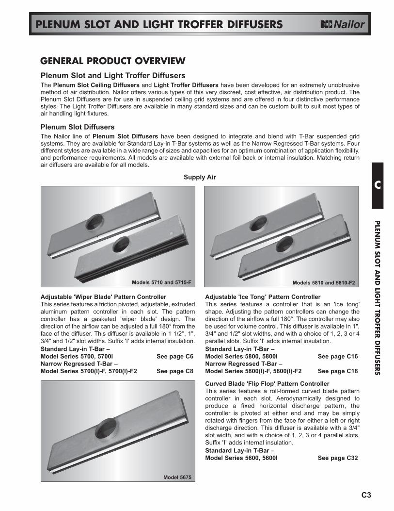
Adjustable 'Wiper Blade' Pattern ControllerThis series features a friction pivoted, adjustable, extrudedaluminum pattern controller in each slot. The patterncontroller has a gasketed 'wiper blade' design. Thedirection of the airflow can be adjusted a full 180° from theface of the diffuser. This diffuser is available in 1 1/2", 1",3/4" and 1/2" slot widths. Suffix 'I' adds internal insulation.Standard Lay-in T-Bar – Model Series 5700, 5700I See page C6Narrow Regressed T-Bar – Model Series 5700(I)-F, 5700(I)-F2 See page C8
Adjustable 'Ice Tong' Pattern ControllerThis series features a controller that is an 'ice tong'shape. Adjusting the pattern controllers can change thedirection of the airflow a full 180°. The controller may alsobe used for volume control. This diffuser is available in 1",3/4" and 1/2" slot widths, and with a choice of 1, 2, 3 or 4parallel slots. Suffix 'I' adds internal insulation.Standard Lay-in T-Bar – Model Series 5800, 5800I See page C16Narrow Regressed T-Bar – Model Series 5800(I)-F, 5800(I)-F2 See page C18
GENERAL PRODUCT OVERVIEW
Curved Blade 'Flip Flop' Pattern ControllerThis series features a roll-formed curved blade patterncontroller in each slot. Aerodynamically designed toproduce a fixed horizontal discharge pattern, thecontroller is pivoted at either end and may be simplyrotated with fingers from the face for either a left or rightdischarge direction. This diffuser is available with a 3/4"slot width, and with a choice of 1, 2, 3 or 4 parallel slots.Suffix 'I' adds internal insulation.Standard Lay-in T-Bar – Model Series 5600, 5600I See page C32
Plenum Slot and Light Troffer DiffusersThe Plenum Slot Ceiling Diffusers and Light Troffer Diffusers have been developed for an extremely unobtrusivemethod of air distribution. Nailor offers various types of this very discreet, cost effective, air distribution product. ThePlenum Slot Diffusers are for use in suspended ceiling grid systems and are offered in four distinctive performancestyles. The Light Troffer Diffusers are available in many standard sizes and can be custom built to suit most types ofair handling light fixtures.
Plenum Slot DiffusersThe Nailor line of Plenum Slot Diffusers have been designed to integrate and blend with T-Bar suspended gridsystems. They are available for Standard Lay-in T-Bar systems as well as the Narrow Regressed T-Bar systems. Fourdifferent styles are available in a wide range of sizes and capacities for an optimum combination of application flexibility,and performance requirements. All models are available with external foil back or internal insulation. Matching returnair diffusers are available for all models.
Models 5810 and 5810-F2
Model 5675
Models 5710 and 5715-F
Supply AirC
PLEN
UM
SLOT A
ND
LIGH
T TRO
FFER D
IFFUSER
S

C4
PLENUM SLOT AND LIGHT TROFFER DIFFUSERS
Return Air Plenums for 5800, 5700, 5600 SeriesThis series of return air plenums are designed to matchand compliment their supply air counterpart. The plenumsare for ductless return and include a light shield. Whererequired, extruded aluminum center tees will be used.Suffix 'I' adds internal insulation.Model Series – – 5700R(I), 5800R(I), 5600R(I) See page C36– 5700R(I)-F, 5800R(I)-F See page C38– 5700R(I)-F2, 5800R(I)-F2 See page C38
Models 5675R, 5810R-F and 5775R-F2
Model 59ND
N Series – Premium Performance, SupplyThis supply diffuser has a 3/4" slot that incorporates anextruded aluminum pattern controller for a fixedhorizontal discharge pattern. This plenum is alsoavailable with a down-blow section that incorporates twohinged pattern controllers to provide a vertical dischargepattern in addition to the horizontal discharge pattern.Suffix 'I' adds internal insulation.Horizontal Discharge – Models 59N, 59NI See page C45Horizontal/Vertical Discharge – Models 59ND, 59NDI See page C45
C
PLE
NU
M S
LOT
AN
D L
IGH
T TR
OFF
ER D
IFFU
SERS
N Series – Premium Performance, Supply/ReturnThe plenum slot diffusers in this series combines a returnair plenum attached to the side of the N Series HorizontalDischarge plenum or the combination Horizontal/VerticalDischarge plenum diffuser offered in the same series.Suffix 'I' adds internal insulation.Horizontal Discharge – Models 59NR, 59NRI See page C45Horizontal/Vertical Discharge – Models 59NDR, 59NDRI See page C45
Model 59NDR
C16
PLENUM SLOT DIFFUSERS
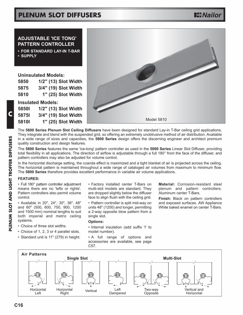
ADJUSTABLE 'ICE TONG'PATTERN CONTROLLER• FOR STANDARD LAY-IN T-BAR• SUPPLY
Uninsulated Models:5850 1/2" (13) Slot Width5875 3/4" (19) Slot Width5810 1" (25) Slot WidthInsulated Models:5850I 1/2" (13) Slot Width5875I 3/4" (19) Slot Width5810I 1" (25) Slot Width
FEATURES:• Full 180° pattern controller adjustmentmeans there are no 'lefts or rights'.Pattern controllers also permit volumecontrol.• Available in 20", 24", 30", 36", 48"and 60" (500, 600, 750, 900, 1200and 1500 mm) nominal lengths to suitboth imperial and metric ceilingsystems.• Choice of three slot widths.• Choice of 1, 2, 3 or 4 parallel slots.• Standard unit is 11" (279) in height.
• Factory installed center T-Bars onmulti-slot models are standard. Theyare dropped slightly below the diffuserface to align flush with the ceiling grid.• Pattern controller is split mid-way onunits 48" (1200) and longer, permittinga 2-way opposite blow pattern from asingle slot.Options:• Internal insulation (add suffix 'I' to model number).• A full range of options andaccessories are available, see pageC57.
Material: Corrosion-resistant steelplenum and pattern controllers.Aluminum center T-Bars.Finish: Black on pattern controllersand exposed surfaces. AW ApplianceWhite baked enamel on center T-Bars.
The 5800 Series Plenum Slot Ceiling Diffusers have been designed for standard Lay-in T-Bar ceiling grid applications.They integrate and blend with the suspended grid, so offering an extremely unobtrusive method of air distribution. Availablein a wide range of sizes and capacities, the 5800 Series design offers the discerning engineer and architect premiumquality construction and design features.The 5800 Series features the same 'ice-tong' pattern controller as used in the 5000 Series Linear Slot Diffuser, providingtotal flexibility in all applications. The direction of airflow is adjustable through a full 180° from the face of the diffuser, andpattern controllers may also be adjusted for volume control.In the horizontal discharge setting, the coanda effect is maximized and a tight blanket of air is projected across the ceiling.The horizontal pattern is maintained throughout a wide range of cataloged air volumes from maximum to minimum flow.The 5800 Series therefore provides excellent performance in variable air volume applications.
Air PatternsSingle Slot Multi-Slot
HorizontalLeft
HorizontalRight Vertical Left
DamperedTwo-wayOpposite
Vertical andHorizontal
Model 5810C
PLE
NU
M S
LOT
AN
D L
IGH
T TR
OFF
ER D
IFFU
SERS
C17
PLENUM SLOT DIFFUSERS
11"(279)
W
2SLOT
S
W
1SLOT
S
W
3SLOT
1/2" (13) TYP.
1 1/4" (32) TYP.
4SLOT
S
W
S
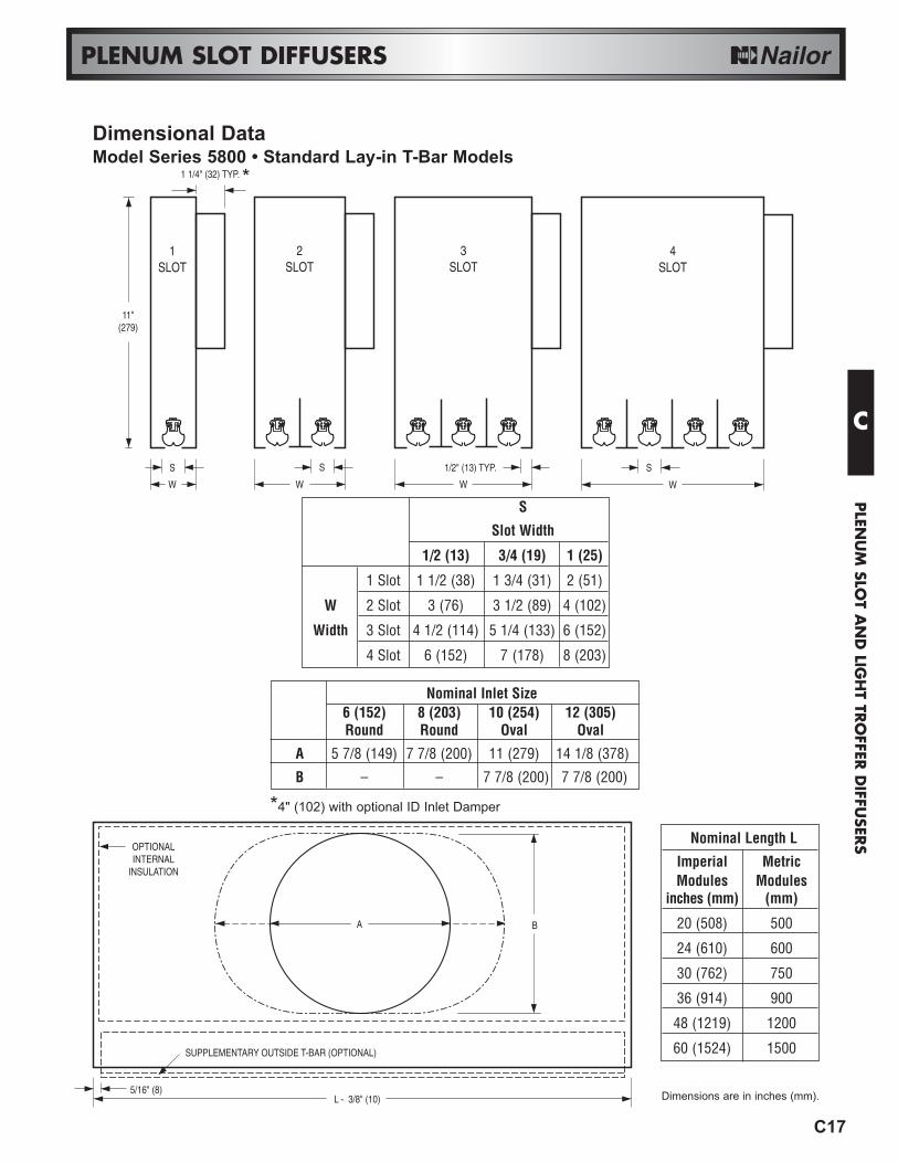
Slot Width
1/2 (13) 3/4 (19) 1 (25)
1 Slot 1 1/2 (38) 1 3/4 (31) 2 (51)
W 2 Slot 3 (76) 3 1/2 (89) 4 (102)
Width 3 Slot 4 1/2 (114) 5 1/4 (133) 6 (152)
4 Slot 6 (152) 7 (178) 8 (203)
Nominal Inlet Size 6 (152) 8 (203) 10 (254) 12 (305)Round Round Oval Oval
A 5 7/8 (149) 7 7/8 (200) 11 (279) 14 1/8 (378)
B – – 7 7/8 (200) 7 7/8 (200)
Dimensional DataModel Series 5800 • Standard Lay-in T-Bar Models
BA
L - 3/8" (10)
OPTIONALINTERNAL
INSULATION
5/16" (8)
SUPPLEMENTARY OUTSIDE T-BAR (OPTIONAL)
*4" (102) with optional ID Inlet Damper
Nominal Length L
Imperial MetricModules Modules
inches (mm) (mm)
20 (508) 500
24 (610) 600
30 (762) 750
36 (914) 900
48 (1219) 1200
60 (1524) 1500
*
Dimensions are in inches (mm).
C
PLEN
UM
SLOT A
ND
LIGH
T TRO
FFER D
IFFUSER
S

C18
Model 5810-F2
PLENUM SLOT DIFFUSERS
ADJUSTABLE 'ICE TONG'PATTERN CONTROLLER• FOR NARROW REGRESSED
T-BAR• SUPPLY
Straddle Mount Models:5850(I)-F 1/2" (13) Slot Width5875(I)-F 3/4" (19) Slot Width5810(I)-F 1" (25) Slot WidthFlat Face Center T-Bar Models:5850(I)-F2 1/2" (13) Slot Width5875(I)-F2 3/4" (19) Slot Width5810(I)-F2 1" (25) Slot Width• Suffix 'I' adds internal insulation
FEATURES:• Full 180° pattern controller adjustmentmeans there are no 'lefts or rights'.• Available in 24" or 48" (600 or 1200)nominal lengths to suit both imperialand metric ceiling systems.• A cross notch is supplied on 48"(1200) long units which allows theplenum to be installed in a 24" x 24"(600 x 600) ceiling grid.• Series 5800-F is available in a oneor two slot configuration and Series5800-F2 is available in a one, two,three, or four slot configurations.
• The single slot units are forinstallation alongside a main runner.• 5800-F two slot unit has a center hatchannel that is designed to straddle amain T-Bar runner.• 5800-F2 multi-slot units include 1"(25) flat face T-Bars.Options:• Internal insulation (add suffix 'I' tomodel number).• A full range of options andaccessories are available, see pageC57.
Material: Corrosion-resistant steel.The series 5800-F2 includes center T-Bars on multi-slot units that areextruded aluminum.Finish: Black on pattern controllersand exposed surfaces. AW ApplianceWhite baked enamel on center T-Bars.
Model Series 5800-F and 5800-F2 Plenum Slot Supply Ceiling Diffusers have been specially developed to integrate withand compliment 'Fineline®' type suspended ceiling grids, thus offering an extremely unobtrusive method of air distribution.Available in a wide range of sizes and capacities, the design offers the optimum combination of application flexibility, highperformance and low cost.This series features an 'ice tong' pattern controller that provides total flexibility in all applications. The direction of airflow isadjustable through a full 180° from the face of the diffuser and pattern controllers may also be adjusted for volume control.In the horizontal discharge setting, the coanda effect is maximized and a tight blanket of air is projected across the ceiling.The horizontal pattern is maintained throughout a wide range of cataloged air volumes from maximum to minimum flow.The single slot units, for all models, are for installation alongside a main T-Bar runner. The series 5800-F two slot unitsincorporate a center hat channel and are designed to straddle, longitudinally, along a main T-Bar runner. The series 5800-F2 multi-slot units incorporate factory installed 1" (25) flat face T-Bars.
C
PLE
NU
M S
LOT
AN
D L
IGH
T TR
OFF
ER D
IFFU
SERS

C19
PLENUM SLOT DIFFUSERS
W
X
FACTORYT-BAR
2SLOT
S
W
1SLOT
S ALL FINELINETEES BY OTHERS
NOMINAL OVERALL PLENUMLENGTH LENGTH L LENGTH P
24 23 3/4 23 3/848 47 3/4 47 3/8
T-BAR TYPE (MANUFACTURER) X Y
A ARMSTRONG SILHOUETTE 1 3/4 (44) 5/16 (8)C CHICAGO METALLIC ULTRALINE 1 5/8 (41) 5/16 (8)D DONN FINELINE® 1 25/32 (45) 5/16 (8)
NOMINAL INLET SIZE6 8 10 12
ROUND ROUND OVAL OVALA 5 7/8 (149) 7 7/8 (200) 11 (279) 14 1/8 (378)B – – 7 7/8 (200) 7 7/8 (200)
Y
9/16 (14)
1/4 (6)
X
Imperial Ceiling Modules (inches)
NOMINAL OVERALL PLENUMLENGTH LENGTH L LENGTH P
600 594 5841200 1194 1184
Metric Ceiling Modules (mm)
Dimensional DataModel Series 5800-F and 5800-F2 • Narrow Regressed T-Bar
11"(279)
P
L
5/8" (16)4" (102) 4" (102)
OPTIONALINTERNAL
INSULATION
MOUNTINGSIDE CLIPS
BA
CROSS NOTCHON 48" (1219)
UNIT IS OPTIONAL.
ENDCAP
SPACER
Fineline® is a registered trademark of USG Interiors Inc.
ALL FINELINE TEESBY OTHERSW
1SLOT
S
1 1/4" (32) TYPICAL
W
X
2SLOT
S
*4" (102) with optional ID Inlet Damper
Model Series 5800-F2Model Series 5800-F
Dimensions are in inches (mm).
*
C
PLEN
UM
SLOT A
ND
LIGH
T TRO
FFER D
IFFUSER
S
MODELS SLOT WIDTH WWIDTH 1 SLOT 2 SLOT
5850-F 1/2 (13) 1 1/2 (38) 3 5/8 (92)5875-F 3/4 (19) 1 3/4 (44) 4 1/8 (105)5810-F 1 (25) 2 (51) 4 5/8 (117)
MODELS SLOT WIDTH WWIDTH 1 SLOT 2 SLOT 3 SLOT 4 SLOT
5850-F2 1/2 (13) 1 1/2 (38) 3 (76) 4 1/2 (114) 6 (152)5875-F2 3/4 (19) 1 3/4 (44) 3 1/2 (89) 5 1/4 (133) 7 (178)5810-F2 1 (25) 2 (51) 4 (102) 6 (152) 8 (203)
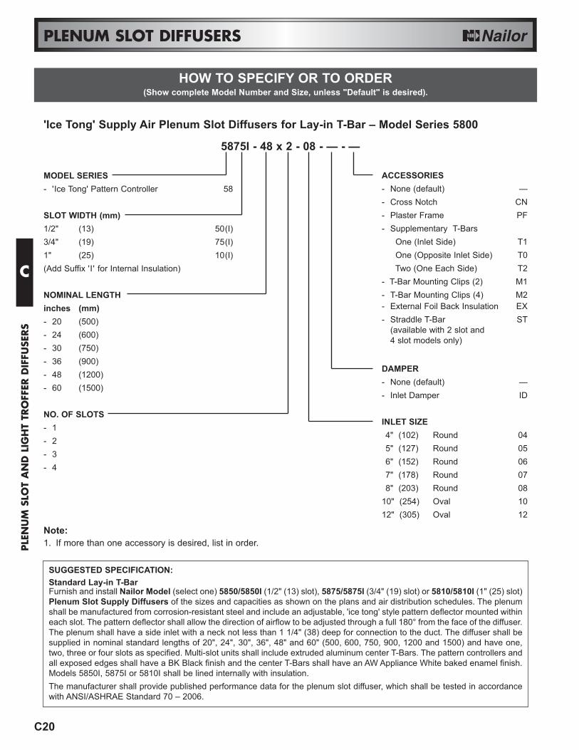
'Ice Tong' Supply Air Plenum Slot Diffusers for Lay-in T-Bar – Model Series 5800
5875I - 48 x 2 - 08 - — - —
MODEL SERIES- 'Ice Tong' Pattern Controller 58
SLOT WIDTH (mm)1/2" (13) 50(I)3/4" (19) 75(I)1" (25) 10(I)(Add Suffix 'I' for Internal Insulation)
NOMINAL LENGTHinches (mm)- 20 (500)- 24 (600)- 30 (750)- 36 (900)- 48 (1200)- 60 (1500)
NO. OF SLOTS- 1- 2- 3- 4
ACCESSORIES- None (default) —- Cross Notch CN- Plaster Frame PF- Supplementary T-Bars
One (Inlet Side) T1One (Opposite Inlet Side) T0Two (One Each Side) T2
- T-Bar Mounting Clips (2) M1 - T-Bar Mounting Clips (4) M2- External Foil Back Insulation EX- Straddle T-Bar ST
(available with 2 slot and 4 slot models only)
DAMPER- None (default) —- Inlet Damper ID
INLET SIZE4" (102) Round 045" (127) Round 056" (152) Round 067" (178) Round 078" (203) Round 08
10" (254) Oval 1012" (305) Oval 12
Note:1. If more than one accessory is desired, list in order.
SUGGESTED SPECIFICATION:Standard Lay-in T-BarFurnish and install Nailor Model (select one) 5850/5850I (1/2" (13) slot), 5875/5875I (3/4" (19) slot) or 5810/5810I (1" (25) slot)Plenum Slot Supply Diffusers of the sizes and capacities as shown on the plans and air distribution schedules. The plenumshall be manufactured from corrosion-resistant steel and include an adjustable, 'ice tong' style pattern deflector mounted withineach slot. The pattern deflector shall allow the direction of airflow to be adjusted through a full 180° from the face of the diffuser.The plenum shall have a side inlet with a neck not less than 1 1/4" (38) deep for connection to the duct. The diffuser shall besupplied in nominal standard lengths of 20", 24", 30", 36", 48" and 60" (500, 600, 750, 900, 1200 and 1500) and have one,two, three or four slots as specified. Multi-slot units shall include extruded aluminum center T-Bars. The pattern controllers andall exposed edges shall have a BK Black finish and the center T-Bars shall have an AW Appliance White baked enamel finish.Models 5850I, 5875I or 5810I shall be lined internally with insulation.The manufacturer shall provide published performance data for the plenum slot diffuser, which shall be tested in accordancewith ANSI/ASHRAE Standard 70 – 2006.
HOW TO SPECIFY OR TO ORDER(Show complete Model Number and Size, unless "Default" is desired).
C20
PLENUM SLOT DIFFUSERS
C
PLE
NU
M S
LOT
AN
D L
IGH
T TR
OFF
ER D
IFFU
SERS
HOW TO SPECIFY OR TO ORDER(Show complete Model Number and Size, unless "Default" is desired).
C21
PLENUM SLOT DIFFUSERS
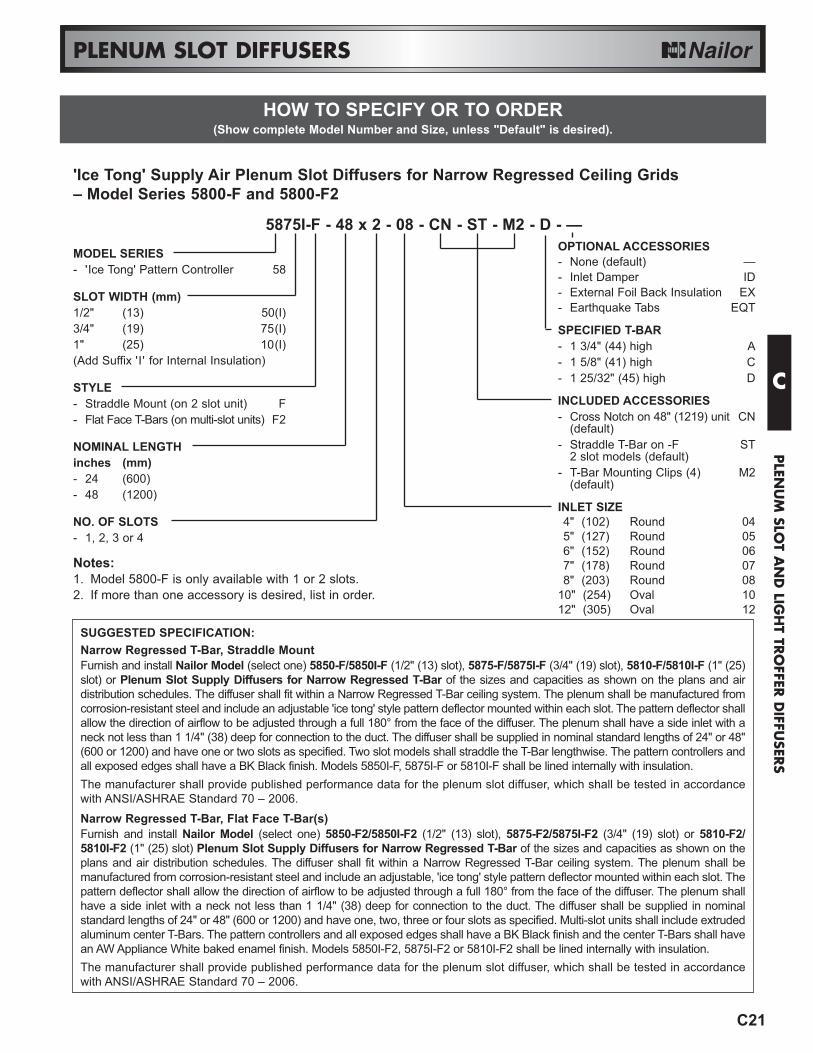
SUGGESTED SPECIFICATION:Narrow Regressed T-Bar, Straddle MountFurnish and install Nailor Model (select one) 5850-F/5850I-F (1/2" (13) slot), 5875-F/5875I-F (3/4" (19) slot), 5810-F/5810I-F (1" (25)slot) or Plenum Slot Supply Diffusers for Narrow Regressed T-Bar of the sizes and capacities as shown on the plans and airdistribution schedules. The diffuser shall fit within a Narrow Regressed T-Bar ceiling system. The plenum shall be manufactured fromcorrosion-resistant steel and include an adjustable 'ice tong' style pattern deflector mounted within each slot. The pattern deflector shallallow the direction of airflow to be adjusted through a full 180° from the face of the diffuser. The plenum shall have a side inlet with aneck not less than 1 1/4" (38) deep for connection to the duct. The diffuser shall be supplied in nominal standard lengths of 24" or 48"(600 or 1200) and have one or two slots as specified. Two slot models shall straddle the T-Bar lengthwise. The pattern controllers andall exposed edges shall have a BK Black finish. Models 5850I-F, 5875I-F or 5810I-F shall be lined internally with insulation.The manufacturer shall provide published performance data for the plenum slot diffuser, which shall be tested in accordancewith ANSI/ASHRAE Standard 70 – 2006.Narrow Regressed T-Bar, Flat Face T-Bar(s)Furnish and install Nailor Model (select one) 5850-F2/5850I-F2 (1/2" (13) slot), 5875-F2/5875I-F2 (3/4" (19) slot) or 5810-F2/5810I-F2 (1" (25) slot) Plenum Slot Supply Diffusers for Narrow Regressed T-Bar of the sizes and capacities as shown on theplans and air distribution schedules. The diffuser shall fit within a Narrow Regressed T-Bar ceiling system. The plenum shall bemanufactured from corrosion-resistant steel and include an adjustable, 'ice tong' style pattern deflector mounted within each slot. Thepattern deflector shall allow the direction of airflow to be adjusted through a full 180° from the face of the diffuser. The plenum shallhave a side inlet with a neck not less than 1 1/4" (38) deep for connection to the duct. The diffuser shall be supplied in nominalstandard lengths of 24" or 48" (600 or 1200) and have one, two, three or four slots as specified. Multi-slot units shall include extrudedaluminum center T-Bars. The pattern controllers and all exposed edges shall have a BK Black finish and the center T-Bars shall havean AW Appliance White baked enamel finish. Models 5850I-F2, 5875I-F2 or 5810I-F2 shall be lined internally with insulation.The manufacturer shall provide published performance data for the plenum slot diffuser, which shall be tested in accordancewith ANSI/ASHRAE Standard 70 – 2006.
'Ice Tong' Supply Air Plenum Slot Diffusers for Narrow Regressed Ceiling Grids – Model Series 5800-F and 5800-F2
5875I-F - 48 x 2 - 08 - CN - ST - M2 - D - —MODEL SERIES- 'Ice Tong' Pattern Controller 58
SLOT WIDTH (mm)1/2" (13) 50(I)3/4" (19) 75(I)1" (25) 10(I)(Add Suffix 'I' for Internal Insulation)
STYLE- Straddle Mount (on 2 slot unit) F- Flat Face T-Bars (on multi-slot units) F2
NOMINAL LENGTHinches (mm)- 24 (600)- 48 (1200)
NO. OF SLOTS- 1, 2, 3 or 4
OPTIONAL ACCESSORIES- None (default) —- Inlet Damper ID- External Foil Back Insulation EX- Earthquake Tabs EQT
SPECIFIED T-BAR- 1 3/4" (44) high A- 1 5/8" (41) high C- 1 25/32" (45) high D
INCLUDED ACCESSORIES- Cross Notch on 48" (1219) unit CN
(default)- Straddle T-Bar on -F ST
2 slot models (default)- T-Bar Mounting Clips (4) M2
(default)
INLET SIZE4" (102) Round 045" (127) Round 056" (152) Round 067" (178) Round 078" (203) Round 08
10" (254) Oval 1012" (305) Oval 12
Notes:1. Model 5800-F is only available with 1 or 2 slots.2. If more than one accessory is desired, list in order.
C
PLEN
UM
SLOT A
ND
LIGH
T TRO
FFER D
IFFUSER
S
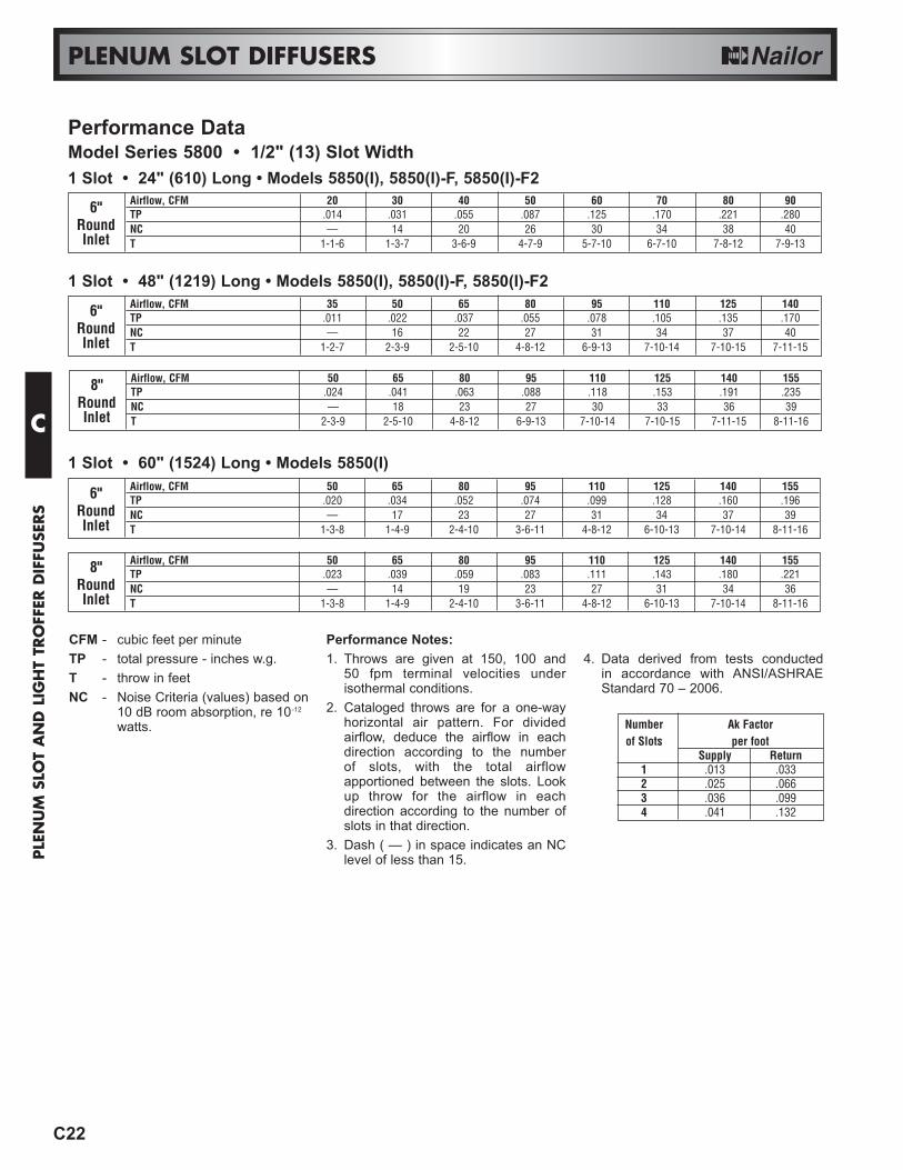
1 Slot • 24" (610) Long • Models 5850(I), 5850(I)-F, 5850(I)-F2
1 Slot • 48" (1219) Long • Models 5850(I), 5850(I)-F, 5850(I)-F2
Airflow, CFM 50 65 80 95 110 125 140 1558" TP .024 .041 .063 .088 .118 .153 .191 .235Round NC — 18 23 27 30 33 36 39Inlet T 2-3-9 2-5-10 4-8-12 6-9-13 7-10-14 7-10-15 7-11-15 8-11-16
Airflow, CFM 20 30 40 50 60 70 80 906" TP .014 .031 .055 .087 .125 .170 .221 .280Round NC — 14 20 26 30 34 38 40Inlet T 1-1-6 1-3-7 3-6-9 4-7-9 5-7-10 6-7-10 7-8-12 7-9-13
Airflow, CFM 35 50 65 80 95 110 125 1406" TP .011 .022 .037 .055 .078 .105 .135 .170Round NC — 16 22 27 31 34 37 40Inlet T 1-2-7 2-3-9 2-5-10 4-8-12 6-9-13 7-10-14 7-10-15 7-11-15
1 Slot • 60" (1524) Long • Models 5850(I)
Airflow, CFM 50 65 80 95 110 125 140 1558" TP .023 .039 .059 .083 .111 .143 .180 .221Round NC — 14 19 23 27 31 34 36Inlet T 1-3-8 1-4-9 2-4-10 3-6-11 4-8-12 6-10-13 7-10-14 8-11-16
Airflow, CFM 50 65 80 95 110 125 140 1556" TP .020 .034 .052 .074 .099 .128 .160 .196Round NC — 17 23 27 31 34 37 39Inlet T 1-3-8 1-4-9 2-4-10 3-6-11 4-8-12 6-10-13 7-10-14 8-11-16
C22
PLENUM SLOT DIFFUSERS
CFM - cubic feet per minuteTP - total pressure - inches w.g.T - throw in feetNC - Noise Criteria (values) based on
10 dB room absorption, re 10-12
watts.
Performance Notes:1. Throws are given at 150, 100 and
50 fpm terminal velocities underisothermal conditions.
2. Cataloged throws are for a one-wayhorizontal air pattern. For dividedairflow, deduce the airflow in eachdirection according to the number of slots, with the total airflowapportioned between the slots. Lookup throw for the airflow in eachdirection according to the number ofslots in that direction.
3. Dash ( — ) in space indicates an NClevel of less than 15.
4. Data derived from tests conductedin accordance with ANSI/ASHRAEStandard 70 – 2006.
Number Ak Factorof Slots per foot
Supply Return1 .013 .0332 .025 .0663 .036 .0994 .041 .132
Performance DataModel Series 5800 • 1/2" (13) Slot Width
C
PLE
NU
M S
LOT
AN
D L
IGH
T TR
OFF
ER D
IFFU
SERS
C23
PLENUM SLOT DIFFUSERS
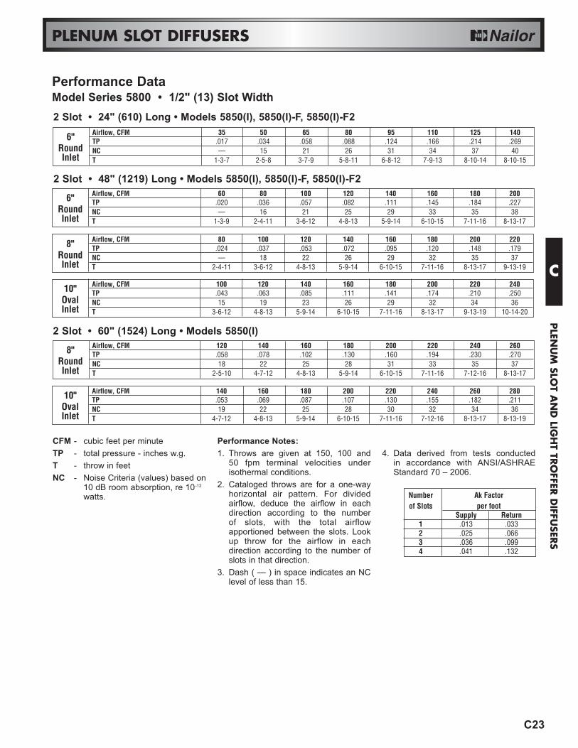
CFM - cubic feet per minuteTP - total pressure - inches w.g.T - throw in feetNC - Noise Criteria (values) based on
10 dB room absorption, re 10-12
watts.
Performance Notes:1. Throws are given at 150, 100 and
50 fpm terminal velocities underisothermal conditions.
2. Cataloged throws are for a one-wayhorizontal air pattern. For dividedairflow, deduce the airflow in eachdirection according to the number of slots, with the total airflowapportioned between the slots. Lookup throw for the airflow in eachdirection according to the number ofslots in that direction.
3. Dash ( — ) in space indicates an NClevel of less than 15.
4. Data derived from tests conductedin accordance with ANSI/ASHRAEStandard 70 – 2006.
Number Ak Factorof Slots per foot
Supply Return1 .013 .0332 .025 .0663 .036 .0994 .041 .132
2 Slot • 60" (1524) Long • Models 5850(I)
Airflow, CFM 140 160 180 200 220 240 260 28010" TP .053 .069 .087 .107 .130 .155 .182 .211Oval NC 19 22 25 28 30 32 34 36Inlet T 4-7-12 4-8-13 5-9-14 6-10-15 7-11-16 7-12-16 8-13-17 8-13-19
Airflow, CFM 120 140 160 180 200 220 240 2608" TP .058 .078 .102 .130 .160 .194 .230 .270Round NC 18 22 25 28 31 33 35 37Inlet T 2-5-10 4-7-12 4-8-13 5-9-14 6-10-15 7-11-16 7-12-16 8-13-17
Airflow, CFM 100 120 140 160 180 200 220 24010" TP .043 .063 .085 .111 .141 .174 .210 .250Oval NC 15 19 23 26 29 32 34 36Inlet T 3-6-12 4-8-13 5-9-14 6-10-15 7-11-16 8-13-17 9-13-19 10-14-20
2 Slot • 24" (610) Long • Models 5850(I), 5850(I)-F, 5850(I)-F2
2 Slot • 48" (1219) Long • Models 5850(I), 5850(I)-F, 5850(I)-F2
Airflow, CFM 80 100 120 140 160 180 200 2208" TP .024 .037 .053 .072 .095 .120 .148 .179Round NC — 18 22 26 29 32 35 37Inlet T 2-4-11 3-6-12 4-8-13 5-9-14 6-10-15 7-11-16 8-13-17 9-13-19
Airflow, CFM 35 50 65 80 95 110 125 1406" TP .017 .034 .058 .088 .124 .166 .214 .269Round NC — 15 21 26 31 34 37 40Inlet T 1-3-7 2-5-8 3-7-9 5-8-11 6-8-12 7-9-13 8-10-14 8-10-15
Airflow, CFM 60 80 100 120 140 160 180 2006" TP .020 .036 .057 .082 .111 .145 .184 .227Round NC — 16 21 25 29 33 35 38Inlet T 1-3-9 2-4-11 3-6-12 4-8-13 5-9-14 6-10-15 7-11-16 8-13-17
Performance DataModel Series 5800 • 1/2" (13) Slot Width
C
PLEN
UM
SLOT A
ND
LIGH
T TRO
FFER D
IFFUSER
S

C24
PLENUM SLOT DIFFUSERS
1 Slot • 24" (610) Long • Models 5875(I), 5875(I)-F, 5875(I)-F2
Airflow, CFM 65 80 95 110 125 140 155 17010" TP .031 .047 .066 .088 .114 .143 .175 .211Oval NC — 18 22 26 29 31 33 36Inlet T 3-5-8 4-6-11 5-7-12 6-9-13 6-10-13 7-11-14 7-11-15 8-12-16
Airflow, CFM 80 95 110 125 140 155 170 18512" TP .052 .079 .099 .128 .160 .196 .236 .279Oval NC 14 18 21 24 27 29 32 34Inlet T 4-6-11 5-7-12 6-9-13 6-10-13 7-11-14 7-11-15 8-12-16 8-13-18
Airflow, CFM 50 65 80 95 110 125 140 1558" TP .016 .028 .042 .059 .080 .103 .129 .158Round NC — 16 21 25 28 30 33 36Inlet T 2-4-7 3-5-8 4-6-11 5-7-12 6-9-13 6-10-13 7-11-14 7-11-15
1 Slot • 48" (1219) Long • Models 5875(I), 5875(I)-F, 5875(I)-F2
Airflow, CFM 40 50 60 70 80 90 100 11010" TP .071 .111 .160 .218 .284 .360 .444 .538Oval NC — 16 21 25 28 31 34 36Inlet T 2-4-7 3-6-9 5-7-10 6-7-10 7-8-11 7-9-12 8-10-13 8-10-14
Airflow, CFM 30 40 50 60 70 80 90 1008" TP .031 .055 .087 .125 .170 .221 .280 .346Round NC — 16 21 25 29 31 34 37Inlet T 1-3-6 2-4-7 3-6-9 5-7-10 6-7-10 7-8-11 7-9-12 8-10-13
Airflow, CFM 20 30 40 50 60 70 80 906" TP .011 .025 .044 .069 .100 .136 .177 .224Round NC — — 18 24 28 32 35 38Inlet T 1-2-4 1-3-6 2-4-7 3-6-9 5-7-10 6-7-10 7-8-11 7-9-12
Airflow, CFM 35 50 65 80 95 110 125 1406" TP .003 .019 .033 .044 .070 .093 .121 .151Round NC — 15 20 25 28 31 34 37Inlet T 1-2-4 2-4-7 3-5-8 4-6-11 5-7-12 6-9-13 6-10-13 7-11-14
1 Slot • 60" (1524) Long • Models 5875(I)
Airflow, CFM 95 110 125 140 155 170 185 20010" TP .041 .055 .071 .089 .109 .131 .155 .181Oval NC 19 22 25 28 30 32 34 36Inlet T 4-6-10 5-7-11 5-8-12 6-9-14 7-10-15 7-11-16 8-12-17 8-13-18
Airflow, CFM 110 125 140 155 170 185 200 21512" TP .055 .071 .089 .109 .131 .155 .181 .209Oval NC 19 22 24 27 29 31 33 35Inlet T 5-7-11 5-8-12 6-9-14 7-10-15 7-11-16 8-12-17 8-13-18 9-14-19
Airflow, CFM 80 95 110 125 140 155 170 1858" TP .032 .045 .060 .077 .097 .119 .143 .169Round NC 17 21 25 28 31 33 35 37Inlet T 3-5-8 4-6-10 5-7-11 5-8-12 6-9-14 7-10-15 7-11-16 8-12-17
Performance DataModel Series 5800 • 3/4" (19) Slot Width
CFM - cubic feet per minuteTP - total pressure - inches w.g.T - throw in feetNC - Noise Criteria (values) based on
10 dB room absorption, re 10-12
watts.Performance Notes:1. Throws are given at 150, 100 and
50 fpm terminal velocities underisothermal conditions.
2. Cataloged throws are for a one-wayhorizontal air pattern. For dividedairflow, deduce the airflow in eachdirection according to the number ofslots, with the total airflow apportionedbetween the slots. Look up throw forthe airflow in each direction accordingto the number of slots in that direction.
3. Dash ( — ) in space indicates an NClevel of less than 15.
4. Data derived from tests conductedin accordance with ANSI/ASHRAEStandard 70 – 2006.
Number Ak Factorof Slots per foot
Supply Return1 .019 .0392 .034 .0783 .046 .1174 .062 .156
C
PLE
NU
M S
LOT
AN
D L
IGH
T TR
OFF
ER D
IFFU
SERS

C25
PLENUM SLOT DIFFUSERS
2 Slot • 24" (610) Long • Models 5875(I), 5875(I)-F, 5875(I)-F2
Airflow, CFM 100 120 140 160 180 200 220 24010" TP .020 .029 .040 .052 .066 .082 .099 .118Oval NC — 17 21 24 27 30 33 35Inlet T 2-6-13 3-6-13 4-7-14 4-10-14 5-11-16 6-12-17 7-13-18 8-14-20
Airflow, CFM 120 140 160 180 200 220 240 26012" TP .031 .042 .055 .078 .087 .105 .125 .146Oval NC — 16 19 24 27 30 33 35Inlet T 3-6-13 4-7-14 4-10-14 5-11-16 6-12-17 7-13-18 8-14-20 9-15-21
Airflow, CFM 80 100 120 140 160 180 200 2208" TP .018 .028 .040 .054 .071 .090 .111 .134Round NC — 15 19 23 27 30 33 36Inlet T 2-5-12 2-6-13 3-6-13 4-7-14 4-10-14 5-11-16 6-12-17 7-13-18
2 Slot • 48" (1219) Long • Models 5875(I), 5875(I)-F, 5875(I)-F2
Airflow, CFM 80 95 110 125 140 155 170 18510" TP .049 .070 .093 .121 .151 .185 .223 .264Oval NC 15 21 25 29 32 35 38 40Inlet T 3-7-10 5-9-12 6-9-13 7-10-14 8-10-15 8-11-17 9-11-19 10-12-20
Airflow, CFM 65 80 95 110 125 140 155 1708" TP .029 .044 .063 .084 .108 .136 .166 .200Round NC 16 21 25 28 31 34 37 40Inlet T 2-5-9 3-7-10 5-9-12 6-9-13 7-10-14 8-10-15 8-11-17 9-11-19
Airflow, CFM 50 65 80 95 110 125 140 1556" TP .022 .037 .055 .078 .105 .135 .170 .208Round NC — 19 24 28 32 35 38 41Inlet T 1-3-8 2-5-9 3-7-10 5-9-12 6-9-13 7-10-14 8-10-15 8-11-17
Airflow, CFM 60 80 100 120 140 160 180 2006" TP .018 .032 .049 .071 .097 .126 .160 .198Round NC — 14 19 23 27 30 33 36Inlet T 1-4-10 2-5-12 2-6-13 3-6-13 4-7-14 4-10-14 5-11-16 6-12-17
2 Slot • 60" (1524) Long • Models 5875(I)
Airflow, CFM 160 180 200 220 240 260 280 30010" TP .040 .051 .063 .076 .090 .106 .123 .141Oval NC 20 23 25 28 30 32 34 36Inlet T 3-7-14 5-8-15 5-8-16 6-9-17 6-10-18 7-11-19 8-13-20 8-15-21
Airflow, CFM 180 200 220 240 260 280 300 32012" TP .036 .044 .054 .064 .075 .087 .100 .113Oval NC 19 22 24 26 28 30 32 34Inlet T 5-8-15 5-8-16 6-9-17 6-10-18 7-11-19 8-13-20 8-15-21 9-16-22
Airflow, CFM 140 160 180 200 220 240 260 2808" TP .044 .057 .072 .089 .108 .128 .151 .175Round NC 20 23 26 28 31 33 35 37Inlet T 2-6-13 3-7-14 5-8-15 5-8-16 6-9-17 6-10-18 7-11-19 8-13-20
Performance DataModel Series 5800 • 3/4" (19) Slot Width
CFM - cubic feet per minuteTP - total pressure - inches w.g.T - throw in feetNC - Noise Criteria (values) based on
10 dB room absorption, re 10-12
watts.Performance Notes:1. Throws are given at 150, 100 and
50 fpm terminal velocities underisothermal conditions.
2. Cataloged throws are for a one-wayhorizontal air pattern. For dividedairflow, deduce the airflow in eachdirection according to the number ofslots, with the total airflow apportionedbetween the slots. Look up throw forthe airflow in each direction accordingto the number of slots in that direction.
3. Dash ( — ) in space indicates an NClevel of less than 15.
4. Data derived from tests conductedin accordance with ANSI/ASHRAEStandard 70 – 2006.
Number Ak Factorof Slots per foot
Supply Return1 .019 .0392 .034 .0783 .046 .1174 .062 .156
C
PLEN
UM
SLOT A
ND
LIGH
T TRO
FFER D
IFFUSER
S

C26
PLENUM SLOT DIFFUSERS
3 Slot • 24" (610) Long • Models 5875(I), 5875(I)-F2
Airflow, CFM 175 200 225 250 275 300 325 35010" TP .041 .054 .068 .085 .102 .122 .143 .166Oval NC 20 23 25 28 30 32 34 36Inlet T 5-9-16 6-10-17 6-11-18 7-12-19 7-13-20 8-14-21 9-15-23 10-16-25
Airflow, CFM 200 225 250 275 300 325 350 37512" TP .033 .042 .052 .063 .074 .087 .101 .116Oval NC 18 21 24 26 28 30 32 34Inlet T 6-10-17 6-11-18 7-12-19 7-13-20 8-14-21 9-15-23 10-16-25 11-17-27
Airflow, CFM 150 175 200 225 250 275 300 3258" TP .046 .063 .082 .103 .128 .154 .184 .216Round NC 18 22 25 28 31 33 35 37Inlet T 3-7-15 5-9-16 6-10-17 6-11-18 7-12-19 7-13-20 8-14-21 9-15-23
3 Slot • 48" (1219) Long • Models 5875(I), 5875(I)-F2
Airflow, CFM 100 120 140 160 180 200 220 24010" TP .040 .058 .078 .102 .130 .160 .194 .230Oval NC 17 21 25 28 31 33 35 37Inlet T 4-7-12 5-8-13 6-9-16 7-10-18 9-12-20 10-13-21 10-14-22 11-14-23
Airflow, CFM 80 100 120 140 160 180 200 2208" TP .025 .038 .055 .075 .098 .125 .154 .186Round NC 14 19 24 28 31 34 36 38Inlet T 3-6-11 4-7-12 5-8-13 6-9-16 7-10-18 9-12-20 10-13-21 10-14-22
Airflow, CFM 60 80 100 120 140 160 180 2006" TP .021 .038 .059 .086 .117 .152 .193 .238Round NC — 18 24 28 32 35 38 41Inlet T 2-5-10 3-6-11 4-7-12 5-8-13 6-9-16 7-10-18 9-12-20 10-13-21
Airflow, CFM 125 150 175 200 225 250 275 3006" TP .060 .087 .118 .154 .195 .240 .291 .346Round NC 18 22 26 30 33 35 37 39Inlet T 2-6-14 3-7-15 5-9-16 6-10-17 6-11-18 7-12-19 7-13-20 8-14-21
3 Slot • 60" (1524) Long • Models 5875(I)
Airflow, CFM 210 240 270 300 330 360 390 42010" TP .052 .068 .086 .106 .129 .153 .186 .208Oval NC 21 24 26 29 31 33 35 37Inlet T 5-10-16 6-11-18 7-12-19 7-13-20 8-14-21 8-15-22 9-16-23 9-17-24
Airflow, CFM 240 270 300 330 360 390 420 45012" TP .040 .057 .068 .076 .090 .106 .123 .141Oval NC 20 22 25 27 29 31 33 35Inlet T 6-11-18 7-12-19 7-13-20 8-14-21 8-15-22 9-16-23 9-17-24 10-17-25
Airflow, CFM 180 210 240 270 300 330 360 3908" TP .056 .076 .100 .126 .156 .189 .224 .263Round NC 19 23 26 29 32 34 36 38Inlet T 3-8-15 5-10-16 6-11-18 7-12-19 7-13-20 8-14-21 8-15-22 9-16-23
CFM - cubic feet per minuteTP - total pressure - inches w.g.T - throw in feetNC - Noise Criteria (values) based on
10 dB room absorption, re 10-12
watts.Performance Notes:1. Throws are given at 150, 100 and
50 fpm terminal velocities underisothermal conditions.
2. Cataloged throws are for a one-wayhorizontal air pattern. For dividedairflow, deduce the airflow in eachdirection according to the number of slots, with the total airflowapportioned between the slots. Lookup throw for the airflow in eachdirection according to the number ofslots in that direction.
3. Dash ( — ) in space indicates an NClevel of less than 15.
4. Data derived from tests conductedin accordance with ANSI/ASHRAEStandard 70 – 2006.
Number Ak Factorof Slots per foot
Supply Return1 .019 .0392 .034 .0783 .046 .1174 .062 .156
Performance DataModel Series 5800 • 3/4" (19) Slot Width
C
PLE
NU
M S
LOT
AN
D L
IGH
T TR
OFF
ER D
IFFU
SERS

C27
PLENUM SLOT DIFFUSERS
4 Slot • 24" (610) Long • Models 5875(I), 5875(I)-F2
Airflow, CFM 220 250 280 310 340 370 400 43010" TP .051 .066 .083 .102 .123 .145 .170 .197Oval NC 20 23 26 29 31 33 35 37Inlet T 5-12-18 6-13-20 7-14-21 9-15-22 10-16-24 11-17-26 12-17-28 12-18-29
Airflow, CFM 250 280 310 340 370 400 430 46012" TP .037 .046 .057 .068 .081 .095 .109 .125Oval NC 19 22 25 27 29 31 33 35Inlet T 6-13-20 7-14-21 9-15-22 10-16-24 11-17-26 12-17-28 12-18-29 13-19-30
Airflow, CFM 190 220 250 280 310 340 370 4008" TP .058 .078 .100 .126 .154 .185 .219 .256Round NC 20 23 26 29 31 34 36 38Inlet T 4-10-16 5-12-18 6-13-20 7-14-21 9-15-22 10-16-24 11-17-26 12-17-28
4 Slot • 48" (1219) Long • Models 5875(I), 5875(I)-F2
Airflow, CFM 125 150 175 200 225 250 275 30010" TP .034 .049 .066 .087 .109 .135 .164 .195Oval NC 19 22 25 29 32 34 36 38Inlet T 5-8-14 7-10-15 8-11-17 9-12-20 9-13-21 10-14-23 11-16-24 13-19-26
Airflow, CFM 100 125 150 175 200 225 250 2758" TP .025 .039 .057 .077 .101 .128 .157 .191Round NC 15 20 24 29 32 35 37 39Inlet T 3-7-13 5-8-14 7-10-15 8-11-17 9-12-20 9-13-21 10-14-23 11-16-24
Airflow, CFM 75 100 125 150 175 200 225 2506" TP .027 .047 .074 .106 .145 .189 .239 .295Round NC — 19 25 29 33 36 39 42Inlet T 2-6-11 3-7-13 5-8-14 7-10-15 8-11-17 9-12-20 9-13-21 10-14-23
Airflow, CFM 160 190 220 250 280 310 340 3706" TP .091 .129 .172 .222 .279 .342 .412 .487Round NC 20 24 27 30 32 35 37 39Inlet T 3-8-15 4-10-16 5-12-18 6-13-20 7-14-21 9-15-22 10-16-24 11-17-26
4 Slot • 60" (1524) Long • Models 5875(I)
Airflow, CFM 260 300 340 380 420 460 500 54010" TP .063 .083 .107 .134 .163 .196 .231 .270Oval NC 21 24 27 30 33 35 37 39Inlet T 4-11-18 6-12-20 8-13-22 10-15-24 11-16-26 12-17-28 13-19-31 14-20-32
Airflow, CFM 300 340 380 420 460 500 540 58012" TP .043 .055 .069 .084 .101 .119 .139 .160Oval NC 20 23 26 28 31 33 35 37Inlet T 6-12-20 8-13-22 10-15-24 11-16-26 12-17-28 13-19-31 14-20-32 14-21-34
Airflow, CFM 220 260 300 340 380 420 460 5008" TP .072 .101 .134 .172 .215 .262 .315 .372Round NC 20 24 27 30 33 35 37 39Inlet T 3-10-16 4-11-18 6-12-20 8-13-22 10-15-24 11-16-26 12-17-28 13-19-31
CFM - cubic feet per minuteTP - total pressure - inches w.g.T - throw in feetNC - Noise Criteria (values) based on
10 dB room absorption, re 10-12
watts.Performance Notes:1. Throws are given at 150, 100 and
50 fpm terminal velocities underisothermal conditions.
2. Cataloged throws are for a one-wayhorizontal air pattern. For dividedairflow, deduce the airflow in eachdirection according to the number of slots, with the total airflowapportioned between the slots. Lookup throw for the airflow in eachdirection according to the number ofslots in that direction.
3. Dash ( — ) in space indicates an NClevel of less than 15.
4. Data derived from tests conductedin accordance with ANSI/ASHRAEStandard 70 – 2006.
Number Ak Factorof Slots per foot
Supply Return1 .019 .0392 .034 .0783 .046 .1174 .062 .156
Performance DataModel Series 5800 • 3/4" (19) Slot Width
C
PLEN
UM
SLOT A
ND
LIGH
T TRO
FFER D
IFFUSER
S

C28
PLENUM SLOT DIFFUSERS
1 Slot • 24" (610) Long • Models 5810(I), 5810(I)-F, 5810(I)-F2
Airflow, CFM 80 95 110 125 140 155 170 18510" TP .029 .041 .055 .071 .089 .109 .131 .155Oval NC 15 19 23 26 29 31 33 35Inlet T 1-3-9 2-4-10 2-5-10 3-5-11 3-6-12 4-7-12 5-8-13 6-9-14
Airflow, CFM 95 110 125 140 155 170 185 20012" TP .045 .060 .077 .097 .119 .143 .169 .198Oval NC 15 18 21 24 27 30 32 34Inlet T 2-4-10 2-5-10 3-5-11 3-6-12 4-7-12 5-8-13 6-9-14 7-10-15
Airflow, CFM 65 80 95 110 125 140 155 1708" TP .018 .027 .038 .050 .065 .082 .100 .120Round NC — 18 22 25 28 31 33 36Inlet T 1-3-7 1-3-9 2-4-10 2-5-10 3-5-11 3-6-12 4-7-12 5-8-13
1 Slot • 48" (1219) Long • Models 5810(I), 5810(I)-F, 5810(I)-F2
Airflow, CFM 40 50 60 70 80 90 100 11010" TP .040 .063 .090 .123 .160 .203 .250 .303Oval NC — 14 19 23 26 28 31 34Inlet T 2-4-6 3-5-7 4-6-8 4-6-9 5-6-9 5-7-10 6-7-10 6-7-10
Airflow, CFM 30 40 50 60 70 80 90 1008" TP .019 .033 .052 .074 .101 .132 .167 .207Round NC — — 16 22 26 29 31 34Inlet T 2-3-5 2-4-6 3-5-7 4-6-8 4-6-9 5-6-9 5-7-10 6-7-10
Airflow, CFM 20 30 40 50 60 70 80 906" TP .006 .014 .026 .040 .058 .078 .102 .130Round NC — — 16 22 26 30 33 36Inlet T 1-2-4 2-3-5 2-4-6 3-5-7 4-6-8 4-6-9 5-6-9 5-7-10
Airflow, CFM 50 65 80 95 110 125 140 1556" TP .016 .026 .040 .056 .076 .098 .123 .150Round NC — 17 22 25 29 32 35 37Inlet T 1-2-5 1-3-7 1-3-9 2-4-10 2-5-10 3-5-11 3-6-12 4-7-12
1 Slot • 60" (1524) Long • Models 5810(I)
Airflow, CFM 95 110 125 140 155 170 185 20010" TP .025 .034 .043 .054 .067 .080 .095 .111Oval NC 15 19 23 25 28 30 32 34Inlet T 1-3-9 2-4-9 3-5-10 3-5-11 4-6-11 5-7-12 6-8-13 6-9-14
Airflow, CFM 110 125 140 155 170 185 200 21512" TP .033 .042 .053 .065 .078 .092 .107 .124Oval NC 16 19 21 25 27 29 31 33Inlet T 2-4-9 3-5-10 3-5-11 4-6-11 5-7-12 6-8-13 6-9-14 7-10-15
Airflow, CFM 80 95 110 125 140 155 170 1858" TP .021 .030 .040 .052 .065 .079 .096 .113Round NC 15 19 23 26 29 31 33 35Inlet T 1-3-7 1-3-9 2-4-9 3-5-10 3-5-11 4-6-11 5-7-12 6-8-13
Performance DataModel Series 5800 • 1" (25) Slot Width
CFM - cubic feet per minuteTP - total pressure - inches w.g.T - throw in feetNC - Noise Criteria (values) based on
10 dB room absorption, re 10-12
watts.Performance Notes:1. Throws are given at 150, 100 and
50 fpm terminal velocities underisothermal conditions.
2. Cataloged throws are for a one-wayhorizontal air pattern. For dividedairflow, deduce the airflow in eachdirection according to the number of slots, with the total airflowapportioned between the slots. Lookup throw for the airflow in eachdirection according to the number ofslots in that direction.
3. Dash ( — ) in space indicates an NClevel of less than 15.
4. Data derived from tests conductedin accordance with ANSI/ASHRAEStandard 70 – 2006.
Number Ak Factorof Slots per foot
Supply Return1 .025 .0512 .045 .1043 .060 .1554 .082 .206
C
PLE
NU
M S
LOT
AN
D L
IGH
T TR
OFF
ER D
IFFU
SERS

C29
PLENUM SLOT DIFFUSERS
2 Slot • 24" (610) Long • Models 5810(I), 5810(I)-F, 5810(I)-F2
Airflow, CFM 140 160 180 200 220 240 260 28010" TP .031 .040 .051 .063 .076 .090 .106 .123Oval NC 18 21 24 27 29 31 33 35Inlet T 4-7-12 5-8-13 6-9-14 6-10-14 7-11-15 8-12-17 8-12-17 9-13-19
Airflow, CFM 160 180 200 220 240 260 280 30012" TP .026 .032 .040 .048 .058 .068 .078 .090Oval NC 17 21 23 25 27 29 31 33Inlet T 5-8-13 6-9-14 6-10-14 7-11-15 8-12-17 8-12-17 9-13-19 9-13-21
Airflow, CFM 120 140 160 180 200 220 240 2608" TP .033 .045 .059 .074 .092 .111 .132 .155Round NC 17 21 24 27 30 32 34 36Inlet T 2-6-9 4-7-12 5-8-13 6-9-14 6-10-14 7-11-15 8-12-17 8-12-17
2 Slot • 48" (1219) Long • Models 5810(I), 5810(I)-F, 5810(I)-F2
Airflow, CFM 80 95 110 125 140 155 170 18510" TP .035 .049 .065 .085 .106 .130 .156 .185Oval NC 15 19 23 26 29 32 35 37Inlet T 4-6-9 5-6-10 6-7-10 6-8-12 7-8-14 7-9-15 8-10-15 8-10-16
Airflow, CFM 65 80 95 110 125 140 155 1708" TP .021 .032 .045 .060 .077 .097 .119 .143Round NC — 19 22 26 29 32 35 38Inlet T 2-5-8 4-6-9 5-6-10 6-7-10 6-8-12 7-8-14 7-9-15 8-10-15
Airflow, CFM 50 65 80 95 110 125 140 1556" TP .016 .028 .042 .059 .080 .103 .129 .158Round NC — 16 22 26 30 33 36 39Inlet T 2-4-7 2-5-8 4-6-9 5-6-10 6-7-10 6-8-12 7-8-14 7-9-15
Airflow, CFM 100 120 140 160 180 200 220 2406" TP .043 .063 .085 .111 .141 .174 .210 .250Round NC 17 21 25 28 31 34 36 38Inlet T 1-4-8 2-6-9 4-7-12 5-8-13 6-9-14 6-10-14 7-11-15 8-12-17
2 Slot • 60" (1524) Long • Models 5810(I)
Airflow, CFM 180 200 220 240 260 280 300 32010" TP .042 .052 .063 .074 .087 .101 .116 .132Oval NC 21 23 25 28 30 32 34 36Inlet T 4-7-12 6-9-14 7-9-15 7-10-16 8-11-17 8-12-18 9-13-19 9-14-21
Airflow, CFM 200 220 240 260 280 300 320 34012" TP .036 .044 .052 .061 .071 .082 .093 .105Oval NC 20 23 25 27 29 31 33 35Inlet T 6-9-14 7-9-15 7-10-16 8-11-17 8-12-18 9-13-19 9-14-21 10-15-22
Airflow, CFM 160 180 200 220 240 260 280 3008" TP .048 .061 .075 .091 .108 .127 .147 .169Round NC 21 24 26 28 30 32 34 36Inlet T 3-6-10 4-7-12 6-9-14 7-9-15 7-10-16 8-11-17 8-12-18 9-13-19
Performance DataModel Series 5800 • 1" (25) Slot Width
CFM - cubic feet per minuteTP - total pressure - inches w.g.T - throw in feetNC - Noise Criteria (values) based on
10 dB room absorption, re 10-12
watts.Performance Notes:1. Throws are given at 150, 100 and
50 fpm terminal velocities underisothermal conditions.
2. Cataloged throws are for a one-wayhorizontal air pattern. For dividedairflow, deduce the airflow in eachdirection according to the number of slots, with the total airflowapportioned between the slots. Lookup throw for the airflow in eachdirection according to the number ofslots in that direction.
3. Dash ( — ) in space indicates an NClevel of less than 15.
4. Data derived from tests conductedin accordance with ANSI/ASHRAEStandard 70 – 2006.
Number Ak Factorof Slots per foot
Supply Return1 .025 .0512 .045 .1043 .060 .1554 .082 .206
C
PLEN
UM
SLOT A
ND
LIGH
T TRO
FFER D
IFFUSER
S

C30
PLENUM SLOT DIFFUSERS
3 Slot • 24" (610) Long • Models 5810(I), 5810(I)-F2
Airflow, CFM 175 200 225 250 275 300 325 35010" TP .036 .047 .060 .074 .089 .106 .125 .145Oval NC 17 20 23 25 27 29 31 33Inlet T 5-7-14 5-8-15 6-8-16 7-9-17 7-10-18 7-11-18 8-12-20 8-13-22
Airflow, CFM 200 225 250 275 300 325 350 37512" TP .026 .032 .040 .048 .058 .068 .078 .090Oval NC 16 19 22 24 26 28 30 32Inlet T 5-8-15 6-8-16 7-9-17 7-10-18 7-11-18 8-12-20 8-13-22 9-14-23
Airflow, CFM 150 175 200 225 250 275 300 3258" TP .039 .053 .069 .088 .108 .131 .156 .183Round NC 17 20 23 26 29 31 33 35Inlet T 3-6-12 5-7-14 5-8-15 6-8-16 7-9-17 7-10-18 7-11-18 8-12-20
3 Slot • 48" (1219) Long • Models 5810(I), 5810(I)-F2
Airflow, CFM 100 120 140 160 180 200 220 24010" TP .024 .034 .046 .061 .077 .095 .115 .136Oval NC 15 19 22 25 28 31 33 35Inlet T 4-6-10 5-7-11 6-8-12 7-9-14 7-10-15 8-10-16 8-11-17 9-11-18
Airflow, CFM 80 100 120 140 160 180 200 2208" TP .018 .028 .040 .054 .071 .090 .111 .134Round NC — 17 22 25 28 31 34 36Inlet T 3-5-9 4-6-10 5-7-11 6-8-12 7-9-14 7-10-15 8-10-16 8-11-17
Airflow, CFM 60 80 100 120 140 160 180 2006" TP .019 .035 .054 .078 .106 .138 .175 .216Round NC — 16 21 25 29 32 35 38Inlet T 2-4-8 3-5-9 4-6-10 5-7-11 6-8-12 7-9-14 7-10-15 8-10-16
Airflow, CFM 125 150 175 200 225 250 275 3006" TP .058 .083 .113 .148 .187 .231 .280 .333Round NC 16 20 24 27 30 33 35 37Inlet T 2-4-10 3-6-12 5-7-14 5-8-15 6-8-16 7-9-17 7-10-18 7-11-18
3 Slot • 60" (1524) Long • Models 5810(I)
Airflow, CFM 210 240 270 300 330 360 390 42010" TP .044 .058 .073 .090 .109 .130 .152 .176Oval NC 19 21 24 26 29 31 33 35Inlet T 4-8-15 6-9-17 6-10-18 7-11-19 7-12-20 8-13-22 8-14-23 9-15-24
Airflow, CFM 240 270 300 330 360 390 420 45012" TP .029 .037 .046 .056 .066 .078 .090 .103Oval NC 18 20 22 25 27 29 31 33Inlet T 6-9-17 6-10-18 7-11-19 7-12-20 8-13-22 8-14-23 9-15-24 10-16-26
Airflow, CFM 180 210 240 270 300 330 360 3908" TP .051 .069 .090 .114 .141 .170 .203 .238Round NC 17 20 24 27 30 32 34 36Inlet T 3-7-13 4-8-15 6-9-17 6-10-18 7-11-19 7-12-20 8-13-22 8-14-23
Performance DataModel Series 5800 • 1" (25) Slot Width
CFM - cubic feet per minuteTP - total pressure - inches w.g.T - throw in feetNC - Noise Criteria (values) based on
10 dB room absorption, re 10-12
watts.Performance Notes:1. Throws are given at 150, 100 and
50 fpm terminal velocities underisothermal conditions.
2. Cataloged throws are for a one-wayhorizontal air pattern. For dividedairflow, deduce the airflow in eachdirection according to the number of slots, with the total airflowapportioned between the slots. Lookup throw for the airflow in eachdirection according to the number ofslots in that direction.
3. Dash ( — ) in space indicates an NClevel of less than 15.
4. Data derived from tests conductedin accordance with ANSI/ASHRAEStandard 70 – 2006.
Number Ak Factorof Slots per foot
Supply Return1 .025 .0512 .045 .1043 .060 .1554 .082 .206
C
PLE
NU
M S
LOT
AN
D L
IGH
T TR
OFF
ER D
IFFU
SERS
C31
PLENUM SLOT DIFFUSERS
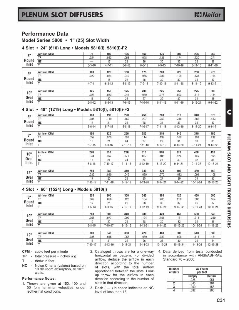
4 Slot • 24" (610) Long • Models 5810(I), 5810(I)-F2
Airflow, CFM 220 250 280 310 340 370 400 43010" TP .044 .057 .071 .087 .105 .124 .145 .168Oval NC 18 21 24 26 28 30 32 34Inlet T 6-8-16 7-10-17 7-11-18 8-12-19 8-13-20 9-14-21 9-14-22 10-15-24
Airflow, CFM 250 280 310 340 370 400 430 46012" TP .032 .040 .049 .059 .070 .082 .094 .108Oval NC 17 20 23 25 27 29 31 33Inlet T 7-10-17 7-11-18 8-12-19 8-13-20 9-14-21 9-14-22 10-15-24 10-16-26
Airflow, CFM 190 220 250 280 310 340 370 4008" TP .052 .070 .091 .114 .139 .168 .199 .232Round NC 18 21 24 27 29 31 33 35Inlet T 5-7-15 6-8-16 7-10-17 7-11-18 8-12-19 8-13-20 9-14-21 9-14-22
4 Slot • 48" (1219) Long • Models 5810(I), 5810(I)-F2
Airflow, CFM 125 150 175 200 225 250 275 30010" TP .023 .033 .046 .059 .075 .093 .112 .134Oval NC 16 20 23 27 29 32 34 36Inlet T 6-8-12 6-8-13 7-9-15 7-10-16 8-11-18 8-11-19 9-13-21 9-14-22
Airflow, CFM 100 125 150 175 200 225 250 2758" TP .022 .034 .049 .066 .087 .109 .135 .164Round NC — 18 22 26 30 32 34 37Inlet T 4-7-11 6-8-12 6-8-13 7-9-15 7-10-16 8-11-18 8-11-19 9-13-21
Airflow, CFM 75 100 125 150 175 200 225 2506" TP .024 .043 .068 .098 .133 .174 .220 .271Round NC — 17 22 26 30 33 36 38Inlet T 3-5-10 4-7-11 6-8-12 6-8-13 7-9-15 7-10-16 8-11-18 8-11-19
Airflow, CFM 160 190 220 250 280 310 340 3706" TP .085 .119 .160 .207 .259 .318 .382 .453Round NC 17 21 25 28 31 33 35 37Inlet T 3-6-14 5-7-15 6-8-16 7-10-17 7-11-18 8-12-19 8-13-20 9-14-21
4 Slot • 60" (1524) Long • Models 5810(I)
Airflow, CFM 260 300 340 380 420 460 500 54010" TP .058 .077 .099 .124 .151 .181 .214 .250Oval NC 19 22 25 28 30 32 34 36Inlet T 6-8-15 7-10-17 8-12-19 9-13-21 9-14-22 10-15-23 10-16-24 11-18-26
Airflow, CFM 300 340 380 420 460 500 540 58012" TP .035 .045 .056 .069 .083 .098 .114 .131Oval NC 18 21 24 26 28 30 32 34Inlet T 7-10-17 8-12-19 9-13-21 9-14-22 10-15-23 10-16-24 11-18-26 12-19-28
Airflow, CFM 220 260 300 340 380 420 460 5008" TP .069 .096 .128 .164 .205 .250 .300 .354Round NC 17 21 25 28 30 32 35 37Inlet T 4-6-13 6-8-15 7-10-17 8-12-19 9-13-21 9-14-22 10-15-23 10-16-24
CFM - cubic feet per minuteTP - total pressure - inches w.g.T - throw in feetNC - Noise Criteria (values) based on
10 dB room absorption, re 10-12
watts.Performance Notes:1. Throws are given at 150, 100 and
50 fpm terminal velocities underisothermal conditions.
2. Cataloged throws are for a one-wayhorizontal air pattern. For dividedairflow, deduce the airflow in eachdirection according to the number of slots, with the total airflowapportioned between the slots. Lookup throw for the airflow in eachdirection according to the number ofslots in that direction.
3. Dash ( — ) in space indicates an NClevel of less than 15.
4. Data derived from tests conductedin accordance with ANSI/ASHRAEStandard 70 – 2006.
Number Ak Factorof Slots per foot
Supply Return1 .025 .0512 .045 .1043 .060 .1554 .082 .206
Performance DataModel Series 5800 • 1" (25) Slot Width
C
PLEN
UM
SLOT A
ND
LIGH
T TRO
FFER D
IFFUSER
S

C36
Model 5675R, 5750R
PLENUM SLOT DIFFUSERS
RETURN AIR PLENUMS• FOR STANDARD LAY-IN T-BAR• COMPLIMENTS THE SUPPLY
SERIES• INCLUDES LIGHT BARRIERS
5700R Series:5750R(I) 1/2" (13) Slot Width5775R(I) 3/4" (19) Slot Width5710R(I) 1" (25) Slot Width5715R(I) 1 1/2" (38) Slot Width5800R Series:5850R(I) 1/2" (13) Slot Width5875R(I) 3/4" (19) Slot Width5810R(I) 1" (25) Slot Width5600R Series:5675R(I) 3/4" (19) Slot Width• Suffix 'I' adds internal insulation
FEATURES:• Available in 20", 24", 30", 36", 48"and 60" (500, 600, 750, 900, 1200and 1500 mm) nominal lengths, to suitboth imperial and metric ceiling grids.• Choice of 1, 2, 3 or 4 parallel slots.• Factory installed center T-Bars onmulti-slot models are standard. Theyare dropped slightly below the diffuserface to align flush with the ceiling grid.
• Series 5700R is available in 4 slotwidths.• Series 5800R is available in 3 slotwidths.• Series 5600R is available in 1 slotwidth.Options:• Internal insulation (add suffix 'I' to model number).• A full range of options andaccessories are available, see pageC57.
Material: Corrosion-resistant steelplenum casing, extruded aluminumcenter T-Bars.Finish: Black on exposed surfaces.AW Appliance White baked enamelon center T-Bars.
These models have been designed as a matching return to compliment their respective supply models. They return roomair to the ceiling plenum and are designed for ductless return applications.The design incorporates a light shield which blocks any stray light in the ceiling plenum, emitted from the rear of the lightfixtures, from emerging through the face. At the same time, it prevents see-through in the opposite direction.
C
PLE
NU
M S
LOT
AN
D L
IGH
T TR
OFF
ER D
IFFU
SERS
C37
PLENUM SLOT DIFFUSERS
7"(178)
W
2SLOT
S
3"(76)
W
1SLOT
S
W
3SLOT
1/2" (13) TYP.
4SLOT
S
W
6"(152)
6"(152)
11"(279)3"
(76)
L - 3/8" (10)5/16" (8)
SUPPLEMENTARY T-BAR (OPTIONAL)
RETURN OPENING
OPTIONAL INTERNAL INSULATION
Nominal Length L
Imperial MetricModules Modules
inches (mm) (mm)
20 (508) 500
24 (610) 600
30 (762) 750
36 (914) 900
48 (1219) 1200
60 (1524) 1500
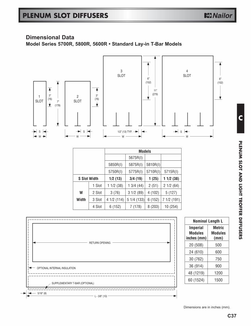
Models5675R(I)
5850R(I) 5875R(I) 5810R(I)
5750R(I) 5775R(I) 5710R(I) 5715R(I)
S Slot Width 1/2 (13) 3/4 (19) 1 (25) 1 1/2 (38)
1 Slot 1 1/2 (38) 1 3/4 (44) 2 (51) 2 1/2 (64)
W 2 Slot 3 (76) 3 1/2 (89) 4 (102) 5 (127)
Width 3 Slot 4 1/2 (114) 5 1/4 (133) 6 (152) 7 1/2 (191)
4 Slot 6 (152) 7 (178) 8 (203) 10 (254)
Dimensional DataModel Series 5700R, 5800R, 5600R • Standard Lay-in T-Bar Models
Dimensions are in inches (mm).
C
PLEN
UM
SLOT A
ND
LIGH
T TRO
FFER D
IFFUSER
S
C38
PLENUM SLOT DIFFUSERS
RETURN AIR PLENUMS• FOR NARROW REGRESSED T-BAR• COMPLIMENTS THE SUPPLY
SERIES• INCLUDES LIGHT BARRIERS
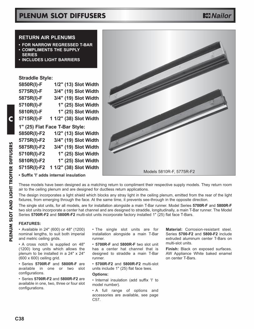
Straddle Style:5850R(I)-F 1/2" (13) Slot Width5775R(I)-F 3/4" (19) Slot Width5875R(I)-F 3/4" (19) Slot Width5710R(I)-F 1" (25) Slot Width5810R(I)-F 1" (25) Slot Width5715R(I)-F 1 1/2" (38) Slot Width1" (25) Flat Face T-Bar Style:5850R(I)-F2 1/2" (13) Slot Width5775R(I)-F2 3/4" (19) Slot Width5875R(I)-F2 3/4" (19) Slot Width5710R(I)-F2 1" (25) Slot Width5810R(I)-F2 1" (25) Slot Width5715R(I)-F2 1 1/2" (38) Slot Width• Suffix 'I' adds internal insulation
FEATURES:• Available in 24" (600) or 48" (1200)nominal lengths, to suit both imperialand metric ceiling grids.• A cross notch is supplied on 48"(1200) long units which allows theplenum to be installed in a 24" x 24"(600 x 600) ceiling grid.• Series 5700R-F and 5800R-F areavailable in one or two slotconfigurations.• Series 5700R-F2 and 5800R-F2 areavailable in one, two, three or four slotconfigurations.
• The single slot units are forinstallation alongside a main T-Barrunner.• 5700R-F and 5800R-F two slot unithas a center hat channel that isdesigned to straddle a main T-Barrunner.• 5700R-F2 and 5800R-F2 multi-slotunits include 1" (25) flat face tees.Options:• Internal insulation (add suffix 'I' to model number).• A full range of options andaccessories are available, see pageC57.
Material: Corrosion-resistant steel.Series 5700-F2 and 5800-F2 includeextruded aluminum center T-Bars onmulti-slot units.Finish: Black on exposed surfaces.AW Appliance White baked enamelon center T-Bars.
These models have been designed as a matching return to compliment their respective supply models. They return roomair to the ceiling plenum and are designed for ductless return applications.The design incorporates a light shield which blocks any stray light in the ceiling plenum, emitted from the rear of the lightfixtures, from emerging through the face. At the same time, it prevents see-through in the opposite direction.The single slot units, for all models, are for installation alongside a main T-Bar runner. Model Series 5700R-F and 5800R-Ftwo slot units incorporate a center hat channel and are designed to straddle, longitudinally, a main T-Bar runner. The ModelSeries 5700R-F2 and 5800R-F2 multi-slot units incorporate factory installed 1" (25) flat face T-Bars.
Models 5810R-F, 5775R-F2
C
PLE
NU
M S
LOT
AN
D L
IGH
T TR
OFF
ER D
IFFU
SERS

C39
PLENUM SLOT DIFFUSERS
W
X
FACTORYT-BAR
2SLOT
S
W
1SLOT
S ALL FINELINE TEESBY OTHERS
3"(76)
3"(76)
NOMINAL OVERALL PLENUMLENGTH LENGTH L LENGTH P
24 23 3/4 23 3/848 47 3/4 47 3/8
T-BAR TYPE (MANUFACTURER) X Y
A ARMSTRONG SILHOUETTE 1 3/4 (44) 5/16 (8)C CHICAGO METALLIC ULTRALINE 1 5/8 (41) 5/16 (8)D DONN FINELINE® 1 25/32 (45) 5/16 (8)
Y
9/16 (14)
1/4 (6)
X
Imperial Ceiling Modules (inches)
NOMINAL OVERALL PLENUMLENGTH LENGTH L LENGTH P
600 594 5841200 1194 1184
Metric Ceiling Modules (mm)
Dimensional DataModel Series 5700R-F, 5700R-F2, 5800R-F and 5800R-F2 • Narrow Regressed T-Bar
7"(178)
P
L
5/8" (16)
4" (102) 4" (102)
OPTIONAL INTERNAL INSULATION
RETURN OPENING
CROSS NOTCHON 48" (1219)
UNIT ISOPTIONAL.
ENDCAP
SPACER
Fineline® is a registered trademark of USG Interiors Inc.
X
2SLOT
S
W
1SLOT
S ALL FINELINE TEESBY OTHERS
MOUNTING SIDE CLIPS
3"(76)
3"(76)
W
Model Series 5700R-F2 and 5800R-F2Model Series 5700R-F and 5800R-F
Models
5850R(I)-F 5875R(I)-F 5810R(I)-F
5775R(I)-F 5710R(I)-F 5715R(I)-F
S Slot Width 1/2 (13) 3/4 (19) 1 (25) 1 1/2 (38)
W 1 Slot 1 1/2 (38) 1 3/4 (44) 2 (51) 2 1/2 (64)
Width 2 Slot 3 5/8 (92) 4 1/8 (105) 4 5/8 (117) 5 5/8 (143)
Models
5850R(I)-F2 5875R(I)-F2 5810R(I)-F2
5775R(I)-F2 5710R(I)-F2 5715R(I)-F2
S Slot Width 1/2 (13) 3/4 (19) 1 (25) 1 1/2 (38)
1 Slot 1 1/2 (38) 1 3/4 (44) 2 (51) 2 1/2 (64)
W 2 Slot 3 (76) 3 1/2 (89) 4 (102) 5 (127)
Width 3 Slot 4 1/2 (114) 5 1/4 (133) 6 (152) 7 1/2 (191)
4 Slot 6 (152) 7 (178) 8 (203) 10 (254)
Dimensions are in inches (mm).
C
PLEN
UM
SLOT A
ND
LIGH
T TRO
FFER D
IFFUSER
S
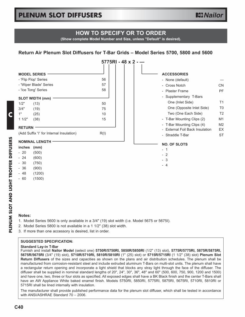
Return Air Plenum Slot Diffusers for T-Bar Grids – Model Series 5700, 5800 and 5600
5775RI - 48 x 2 - —
MODEL SERIES- 'Flip Flop' Series 56- 'Wiper Blade' Series 57- 'Ice Tong' Series 58
SLOT WIDTH (mm)1/2" (13) 503/4" (19) 751" (25) 101 1/2" (38) 15
RETURN(Add Suffix 'I' for Internal Insulation) R(I)
NOMINAL LENGTHinches (mm)- 20 (500)- 24 (600)- 30 (750)- 36 (900)- 48 (1200)- 60 (1500)
ACCESSORIES- None (default) —- Cross Notch CN- Plaster Frame PF- Supplementary T-Bars
One (Inlet Side) T1One (Opposite Inlet Side) T0Two (One Each Side) T2
- T-Bar Mounting Clips (2) M1- T-Bar Mounting Clips (4) M2- External Foil Back Insulation EX- Straddle T-Bar ST
NO. OF SLOTS- 1- 2- 3- 4
Notes:1. Model Series 5600 is only available in a 3/4" (19) slot width (i.e. Model 5675 or 5675I).2. Model Series 5800 is not available in a 1 1/2" (38) slot width.3. If more than one accessory is desired, list in order.
SUGGESTED SPECIFICATION:Standard Lay-in T-Bar Furnish and install Nailor Model (select one) 5750R/5750RI, 5850R/5850RI (1/2" (13) slot), 5775R/5775RI, 5875R/5875RI,5675R/5675RI (3/4" (19) slot), 5710R/5710RI, 5810R/5810RI (1" (25) slot) or 5715R/5715RI (1 1/2" (38) slot) Plenum SlotReturn Diffusers of the sizes and capacities as shown on the plans and air distribution schedules. The plenum shall bemanufactured from corrosion-resistant steel and include extruded aluminum T-Bars on multi-slot units. The plenum shall havea rectangular return opening and incorporate a light shield that blocks any stray light through the face of the diffuser. Thediffuser shall be supplied in nominal standard lengths of 20", 24", 30", 36", 48" and 60" (500, 600, 750, 900, 1200 and 1500)and have one, two, three or four slots as specified. All exposed edges shall have a BK Black finish and the center T-Bars shallhave an AW Appliance White baked enamel finish. Models 5750RI, 5850RI, 5775RI, 5875RI, 5675RI, 5710RI, 5810RI or5715RI shall be lined internally with insulation.The manufacturer shall provide published performance data for the plenum slot diffuser, which shall be tested in accordancewith ANSI/ASHRAE Standard 70 – 2006.
HOW TO SPECIFY OR TO ORDER(Show complete Model Number and Size, unless "Default" is desired).
C40
PLENUM SLOT DIFFUSERS
C
PLE
NU
M S
LOT
AN
D L
IGH
T TR
OFF
ER D
IFFU
SERS

HOW TO SPECIFY OR TO ORDER(Show complete Model Number and Size, unless "Default" is desired).
C41
PLENUM SLOT DIFFUSERS
SUGGESTED SPECIFICATION:Narrow Regressed T-Bar – Straddle MountFurnish and install Nailor Model (select one) 5850R-F/5850RI-F (1/2" (13) slot), 5775R-F/5775RI-F, 5875R-F/5875RI-F (3/4"(19) slot), 5710R-F/5710RI-F, 5810R-F/5810RI-F (1" (25) slot) or 5715R-F/5715RI-F (1 1/2" (38) slot) Plenum Slot ReturnDiffusers for Narrow Regressed T-Bar of the sizes and capacities as shown on the plans and air distribution schedules. Theplenum shall fit within a Narrow Regressed T-Bar ceiling system. The plenum shall be manufactured from corrosion-resistantsteel. The plenum shall have a rectangular return opening and incorporate a light shield that blocks any stray light through theface of the diffuser. The diffuser shall be supplied in nominal standard lengths of either 24" or 48" (600 or 1200) and have oneor two slots as specified. Two slot models shall straddle the T-Bar lengthwise. All exposed edges shall have a BK Black finish.Models 5850RI-F, 5775RI-F, 5875RI-F, 5710RI-F, 5810RI-F or 5715RI-F shall be lined internally with insulation.The manufacturer shall provide published performance data for the plenum slot diffuser, which shall be tested in accordancewith ANSI/ASHRAE Standard 70 – 2006.Narrow Regressed T-Bar – Flat Face T-Bar(s)Furnish and install Nailor Model (select one) 5850R-F2/5850RI-F2 (1/2" (13) slot), 5775R-F2/5775RI-F2, 5875R-F2/5875RI-F2(3/4" (19) slot), 5710R-F2/5710RI-F2, 5810R-F2/5810RI-F2 (1" (25) slot) or 5715R-F2/5715RI-F2 (1 1/2" (38) slot) PlenumSlot Return Diffusers for Narrow Regressed T-Bar of the sizes and capacities as shown on the plans and air distributionschedules. The plenum shall fit within a Narrow Regressed T-Bar ceiling system. The plenum shall be manufactured fromcorrosion-resistant steel and include extruded aluminum T-Bars on multi-slot units. The plenum shall have a rectangular returnopening and incorporate a light shield that blocks any stray light through the face of the diffuser. The diffuser shall be suppliedin nominal standard lengths of either 24" or 48" (600 or 1200) and have one, two, three or four slots as specified. All exposededges shall have a BK Black finish and the center T-Bars shall have an AW Appliance White baked enamel finish. Models5850RI-F2, 5775RI-F2, 5875RI-F2, 5710RI-F2, 5810RI-F2 or 5715RI-F2 shall be lined internally with insulation.The manufacturer shall provide published performance data for the plenum slot diffuser, which shall be tested in accordancewith ANSI/ASHRAE Standard 70 – 2006.
Return Air Plenum Slot Diffusers for Narrow Regressed Ceiling Grids – Model Series 5700R-F, 5700R-F2, 5800R-F and 5800R-F2
5775RI-F - 48 x 2 - CN - ST - M2 - D - —
MODEL SERIES- 'Wiper Blade' Pattern Controller 57- 'Ice Tong' Pattern Controller 58
SLOT WIDTH (mm)1/2" (13) 50R(I)3/4" (19) 75R(I)1" (25) 10R(I)1 1/2" (38) 15R(I)(Add Suffix 'I' for Internal Insulation)
STYLE- Straddle Mount (on 2 slot unit) F- Flat Face T-Bars (on multi-slot units) F2
NOMINAL LENGTHinches (mm)- 24 (600)- 48 (1200)
OPTIONAL ACCESSORIES- None (default) —- Inlet Damper ID- External Foil Back Insulation EX- Earthquake Tabs EQT
SPECIFIED T-BAR- 1 3/4" (44) high A- 1 5/8" (41) high C- 1 25/32" (45) high D
INCLUDED ACCESSORIES- Cross Notch on 48" (1219) unit CN
(default)- Straddle T-Bar on -F ST
2 slot models (default)- T-Bar Mounting Clips (4) M2
(default)NO. OF SLOTS- 1, 2, 3 or 4
Notes:1. Models with '-F' are only available with 1 or 2 slots.2. If more than one accessory is desired, list in order.
C
PLEN
UM
SLOT A
ND
LIGH
T TRO
FFER D
IFFUSER
S

C43
PLENUM SLOT DIFFUSERS
CFM - cubic feet per minuteSP - static pressure - inches w.g.NC - Noise Criteria (values) based
on 10 dB room absorption, re 10-12 watts.
Performance Notes:1. Data derived from tests conducted in
accordance with ANSI/ASHRAEStandard 70 – 2006.
3/4" (19) Slot • 24" (610) Long • Models 5875R(I), 5875R(I)-F, 5875R(I)-F2Airflow, CFM 30 45 60 75 90 105 120 135 150
1 Slot Negative SP .010 .021 .038 .059 .085 .116 .152 .192 .238NC — — — 12 18 22 26 29 32Airflow, CFM 60 90 120 150 180 210 240 270 300
2 Slot Negative SP .010 .021 .038 .059 .085 .116 .152 .192 .238NC — — — 15 21 25 29 32 35
3/4" (19) Slot • 48" (1219) Long • Models 5875R(I), 5875R(I)-F, 5875R(I)-F2Airflow, CFM 60 90 120 150 180 210 240 270 300
1 Slot Negative SP .010 .021 .038 .059 .085 .116 .152 .192 .238NC — — — 12 18 22 26 29 32Airflow, CFM 120 180 240 300 360 420 480 540 600
2 Slot Negative SP .010 .021 .038 .059 .085 .116 .152 .192 .238NC — — — 15 21 25 29 32 35
1" (25) Slot • 24" (610) Long • Models 5810R(I), 5810R(I)-F, 5810R(I)-F2Airflow, CFM 40 60 80 100 120 140 160 180 200
1 Slot Negative SP .010 .021 .038 .059 .085 .116 .152 .192 .238NC — — — 12 18 22 26 29 32Airflow, CFM 80 120 160 200 240 280 320 360 400
2 Slot Negative SP .010 .021 .038 .059 .085 .116 .152 .192 .238NC — — — 15 21 25 29 32 35
1" (25) Slot • 48" (1219) Long • Models 5810R(I), 5810R(I)-F, 5810R(I)-F2Airflow, CFM 80 120 160 200 240 280 320 360 400
1 Slot Negative SP .010 .021 .038 .059 .085 .116 .152 .192 .238NC — — — 12 18 22 26 29 32Airflow, CFM 160 240 320 400 480 560 640 720 800
2 Slot Negative SP .010 .021 .038 .059 .085 .116 .152 .192 .238NC — — — 15 21 25 29 32 35
1/2" (13) Slot • 24" (610) Long • Models 5850R(I), 5850R(I)-F, 5850R(I)-F2Airflow, CFM 20 30 40 50 60 70 80 90 100
1 Slot Negative SP .010 .021 .038 .059 .085 .116 .152 .192 .238NC — — — 12 18 22 26 29 32Airflow, CFM 40 60 80 100 120 140 160 180 200
2 Slot Negative SP .010 .021 .038 .059 .085 .116 .152 .192 .238NC — — — 15 21 25 29 32 35
1/2" (13) Slot • 48" (1219) Long • Models 5850R(I), 5850R(I)-F, 5850R(I)-F2Airflow, CFM 40 60 80 100 120 140 160 180 200
1 Slot Negative SP .010 .021 .038 .059 .085 .116 .152 .192 .238NC — — — 12 18 22 26 29 32Airflow, CFM 80 120 160 200 240 280 320 360 400
2 Slot Negative SP .010 .021 .038 .059 .085 .116 .152 .192 .238NC — — — 15 21 25 29 32 35
Performance DataModel Series 5800R
C
PLEN
UM
SLOT A
ND
LIGH
T TRO
FFER D
IFFUSER
S

C57
PLENUM SLOT DIFFUSERS
O.A. = D + 1 3/4" (44)
NECK = NOMINAL - 1/8" (3)
O.A. = NOMINAL + 1 3/8" (35)
NECK = D + 1/4" (6)
1 5/8"(41)
7/16"(11)
4" (102)
1 1/2"(38)
PLENUMSLOT
DIFFUSER
CEILING
1 5/32" (29)
Model Series: 5700, 5800, 5600, 59N, 59BS
PF Slot Diffuser Plaster FrameSlot diffuser mounting frames allowplenum slot diffusers to be installed indrywall or plaster ceilings. Installation ofthe frame in the ceiling is by others. (Note: Diffuser will not fit through aplaster frame opening).Material: Extruded aluminum withmitered corners.Recommended Ceiling Openingdimensions:Width = Diffuser Width (D) + 1/2" (13)Length = Nominal Diffuser Length + 1/4" (6)
ID Inlet Damper(Supply only)
Mounting ClipsM1 One Side (2 opposite inlet side)M2 Both sides (4)
Supplementary T-BarsT1 One on inlet sideT0 One opposite inlet sideT2 Two on both sides
Note: Center T-Bars are supplied byNailor as standard.
T2T0T1
Options and Accessories
C
PLEN
UM
SLOT A
ND
LIGH
T TRO
FFER D
IFFUSER
S
C58
PLENUM SLOT DIFFUSERS
1 5/8"(41)
5/8"(16)
2SLOT
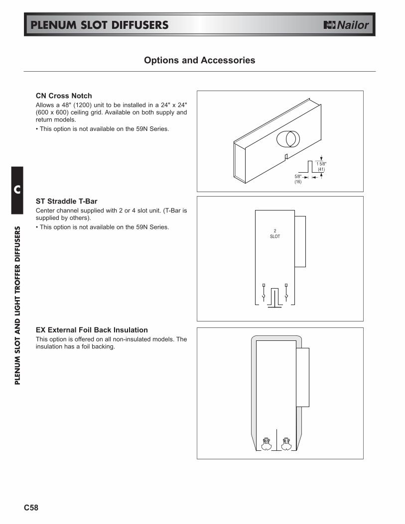
CN Cross NotchAllows a 48" (1200) unit to be installed in a 24" x 24"(600 x 600) ceiling grid. Available on both supply andreturn models.• This option is not available on the 59N Series.
ST Straddle T-BarCenter channel supplied with 2 or 4 slot unit. (T-Bar issupplied by others).• This option is not available on the 59N Series.
EX External Foil Back InsulationThis option is offered on all non-insulated models. Theinsulation has a foil backing.
Options and Accessories
C
PLE
NU
M S
LOT
AN
D L
IGH
T TR
OFF
ER D
IFFU
SERS