plexo tcs - bartec - weltmarktführer im explosionsschutz€¦ · 21-59po-7d0002-09/2017-eht-414922...
TRANSCRIPT

21-5
9PO-
7D00
02-0
9/20
17-E
HT-4
1492
2
PLEXO TCS
Installation and Operation Heating cable connection, splice and end termination system with BARTEC self limiting heating cables Type PSBL, PSB, MSB and HSB
TC RU C-DE.ГБ06.B.00230

21-5
9PO-
7D00
02-0
9/20
17-E
HT-4
1492
2
EN 2/20
PLEXO TCS Operation instructions
1. Intended Use
1.1 General Points
When operated in accordance with the intended purpose, the PLEXO TCS Type 27-1100-..../.... Ex heating system, consisting of a PLEXO TCS plug connector (heating cable supply connection, end termination or splice) and the BARTEC self-limiting PSBL, PSB, MSB and HSB parallel heating cables can be used as a stationary system in hazardous (potentially explosive) areas in which an explosive atmosphere of gas, vapour, mist or a dust/air mixtures can be expected to develop sometimes.
It is used in Zones 1, 2, 21 or 22 in accordance with the certified explosion group II and the specified temperature classes.
1.3 Usable Heating Cables
The following heating cables can be used in the PLEXO TCS heating system:
PSBL heating cables, type 07-5807-.... KEMA 02 ATEX 2326 U/IECEx KEM 07.0047U or
PSB heating cables, type 07-5801- KEMA 02 ATEX 2326 U/IECEx KEM 07.0047U or
MSB heating cables, type 07-5804-2... DEKRA 12 ATEX 0044 U/IECEx DEK 12.0004U or
HSB heating cables, type 07-5803-.... KEMA 02 ATEX 2327 U/IECEx KEM 07.0048U
2. Product Description
2.1 General Points
The PLEXO TCS heating system is suitable for use with BARTEC self-limiting heating cables. The modular PLEXO TCS plug connector allows a heating cable connection, splice or end termination to be assembled easily and safely. The PLEXO TCS connectors can be plugged in and are produced with patented sealing and clamping technology.
1.2. Usable PLEXO TCS Plug-In Connectors
Version Use
Supply connection, type 27-59P1-..../....
The connection serves as a joining element between the mains cables/sheathed cables and heating cables.
Splice connection, type 27-59P2-..../....
The splice serves to join heating cables together
End termination, type 27-59P3-..../....
The end termination serves as an explosion-proof end termination for heating circuits which facilitate length extensions.
Code Code for Variations Description
A Rated voltage range of heating cable
01
110 V to 120 V208 V to 254 V
B Heating cable family used 0123
PSBLPSBMSBHSB
Overview of heating system types
Type no. 27 - 1 1 0 0 - . . 5 0
Code no. A B

21-5
9PO-
7D00
02-0
9/20
17-E
HT-4
1492
2
EN 3/20ReservationTechnical data subject to change without notice. Changes, errors and misprints may not be used as a basis for any claim for damages.
Overview of heating cable connection types
Type Description Oval sealing A (for heating cables)
Round sealing B (for supply cables)
Colour Sealing area Colour Sealing area
27-59P1-101./....
Heating cable connection orangePSBL, PSB, MSB, HSB heating cables
yellow 8 ≤ D ≤ 10 mm
27-59P1-201./.... beige 10 ≤ D ≤ 12 mm
27-59P1-301./.... orange 12 ≤ D ≤ 14 mm
27-59P1-401./.... blue 14 ≤ D ≤ 16 mm
Heating Cable Connection (Type 27-59P1-..../....)
Overview of heating cable connection parts
1 Heating cable housing2 Heating cable sealing unit3 Insulating divider4 Heating cable clamping unit5 Supply cable clamping unit6 Supply cable sealing unit
7 Supply cable housingA Heating cable sealingB Supply cable sealing2 - 4 Connection unit plug-in - connector heating cable5 - 6 Connection unit socket - supply cable
plug side socket side
21 3 4 5 6 7
Connection unit plug-in - connector heating cable
Connection unit socket - supply cable
A B
green point blue point

21-5
9PO-
7D00
02-0
9/20
17-E
HT-4
1492
2PLEXO TCS Operation instructions
EN 4/20
Overview of heating cable splice types
Type Description Oval sealing A (for heating cables)
Colour Sealing area
27-59P2-011./.... Heating cable splice orange PSBL, PSB, MSB, HSB heating cables
2.3 Heating Cable Splice (Type 27-59P2-..../....)
Overview of heating cable splice parts
1 Heating cable housing2 Heating cable sealing unit3 Insulating divider4 Heating cable clamping unit5 Heating cable splice clamping unit6 Heating cable splice sealing unit
7 Heating cable splice housing A Heating cable sealingC Heating cable sealing2 - 4 Connection unit plug - heating cable 5 - 6 Connection unit socket - heating cable
green point yellow point
plug side socket side
Connection unit plug - heating cable
Connection unit socket - heating cable
A C
21 3 34 5 6 7
21-5
9PO-
7D00
02-0
9/20
17-E
HT-4
1492
2
EN 5/20ReservationTechnical data subject to change without notice. Changes, errors and misprints may not be used as a basis for any claim for damages.
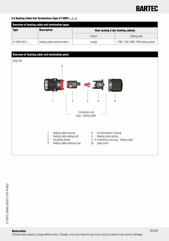
Overview of heating cable end termination types
Type Description Oval sealing A (for heating cables)
Colour Sealing area
27-59P3-001./.... Heating cable end termination orange PSBL, PSB, MSB, HSB heating cables
2.4 Heating Cable End Termination (Type 27-59P3-..../....)
Overview of heating cable end termination parts
1 Heating cable housing2 Heating cable sealing unit3 Insulating divider4 Heating cable clamping unit
plug side
21 3 4 8
Connection unit plug - heating cable
8 End termination housingA Heating cable sealing2 - 4 Connection unit plug - heating cable green point
A

21-5
9PO-
7D00
02-0
9/20
17-E
HT-4
1492
2PLEXO TCS Operation instructions
EN 6/20
3. Safety Instructions
Marking
Particularly important points in these instruc-tions are marked with a symbol:
The DANGER signs draws attention to a dan-ger which will lead to death or serious injury if not avoided.
The WARNING sign draws attention to a dan-ger which can lead to death or serious injury if it is not avoided.
The CAUTION sign draws attention to a danger which can lead to injuries if it is not avoided.
The ATTENTION sign draws attention to mea-sures to prevent damage to property.
Note
Important instructions and information on effective, economical & environmentally com-patible handling.
Safety Instructions
To prevent any life-threatening injuries and damage to property occurring when the PLEXO TCS system is used, it is im-portant that all users read these Operating and Installation Instructions carefully and observe and apply them.
The PLEXO TCS heating system may be used only within the limits specified in the technical data.
The PLEXO TCS plug-in connector must not be opened while the heating circuit is energized as there is then a risk of life-threatening injuries and damage to property. The heating circuit or device must be completely disconnected from the mains if there is a chance of live parts being touched during work.
The outer jacket of the PLEXO TCS plug-in connector may be cleaned with a damp cloth only as there is a potential risk of electrostatic discharging if a dry cloth is used.
When electrical systems are used in haz-ardous areas the relevant installation and operating rules (e.g. Directive 1999/92/EC, Directive 94/9/EC, IEC/EN 60079-14, IEC/ EN 60079-17 and the DIN VDE series 0100) and the specifications on the type label must be observed.
Conductive parts from other components must be incorporated into the (protective conductor) safety measures to provide protection against indirect contact.
The general points in the applicable stat-utory rules and other binding directives on workplace safety, accident prevention and environmental protection must be complied with. Always follow the safety instructions.
For each electric circuit a residual-current circuit-breaker and a means of isolating all supply conductors from the current supply must be provided.
The middle terminal must always be used for the protective earth (earthing). The splicing must always be in-corporated in the PE conductor safety measures. A device to protect against earth faults in accordance with the system earthing must be used. The protective braiding on the heating cable must be connected to the supply cable´s protective earth conductor (see IEC/EN 60079-30-1, Section 4.3.).
When installing the PLEXO TCS plug-in connector, the tightening torques specified in these operating in-structions must be observed.
Whenever you carry out assembly or servicing work, always check the affected sealings visually for damage and make sure they are positioned correctly.
Installation and commissioning may be done only by trained specialized person-nel in conformance to the manufacturer´s specifications and the applicable installa-tion standards.
Maintenance and troubleshooting mea-sures may be performed only by autho-rized people, qualified personnel or elec-tricians. Before starting operation again, check conformance with the applicable
laws and directives. The respective safety instructions must be observed when doing maintenance work or troubleshooting.
Stop operation, assembly or maintenance if there are discrepancies between the PLEXO TCS operating in-structions and the technical documents or design doc-uments and/or the situation on site and consult BARTEC.
Utilisation in areas other than those spec-ified or the modification of the product by anyone other than the manufacturer is not permitted and will exempt BARTEC from liability for defects or any further liability.
The acceptance test report for the heating system operation must be filled in com-pletely and signed (see Chapter 9). The requirements in the separately certified BARTEC heating cables must be observed in accor-dance with the operating instruc-tions. For claims under guarantee the submission of a correctly and completely filled-in acceptance and test report is man-datory.
The owner / managing operator of an elec-trical system in a hazardous environment must keep the equipment in an orderly condition, operate it in accordance with regulations, monitor it and do the required maintenance and repairs (IEC/ EN 60079-14, IEC/EN 60079-17, IEC/EN 60079-19, IEC/EN 60079-30- 1, Section 4.3.). The correct functioning of the PLEXO TCS heating system must be checked at the in-spection intervals specified in the German Ordinance on Industrial Safety and Health (BetrSichV).
Optional temperature monitoring and control units may be used only within the limits of the specified technical data (see marking, type label and acceptance test report).
The classification of the temperature class of the heating system is done from the operator depending in the used heating cable. The ambient temperature range of the heating system depends also of the used heating cable. This information re-corded on the operator side accordance with the specifications in this operating instructions/acceptance report. The docu-mentation must be kept sure.

21-5
9PO-
7D00
02-0
9/20
17-E
HT-4
1492
2
EN 7/20ReservationTechnical data subject to change without notice. Changes, errors and misprints may not be used as a basis for any claim for damages.
4.2 PLEXO Plug-In Connectors
Rated insulation voltage 320 V
Rated connection capacity 0.5 - 4 mm²
Working temperature range - 60 °C ≤ T ≤ +150 °C
Area of use of PLEXO plug-in connector with heating cables PSBL heating cables, type 07-5807-...., KEMA 02 ATEX 2326 U/IECEx KEM 07.0047U
PSB heating cables, type 07-5801-...., KEMA 02 ATEX 2326 U/IECEx KEM 07.0047U
MSB heating cables, type 07-5804-2..., DEKRA 12 ATEX 0044 U/IECEx DEK 12.0004U
HSB heating cables, type 07-5803-...., KEMA 02 ATEX 2327 U/IECEx KEM 07.0048U
Sealing area for supply cables 8 ≤ D ≤ 16 mm (for 27-59P1-..../.... types)
4. Technical data
4.1 PLEXO TCS Heating system
System Type 27-1100-..../....
Rated voltage Max. 254 V, the data for the parallel heating cable must be observed
Rated connection capacity 0.5 - 4 mm²
Maximum heating circuit length of the system In conformance to the specifications in the type examination certificate/IECEx approval for the respective heating cable family (The values specified there refer to the fuse rating/minimum cut-in tem-perature).
Degree of protection in conformance to IEC EN 60529 IP 65 (IEC EN 60079-0); IP 66, IP 68 (IEC EN 60529)
System Type 27-1100-.0../.... (with PSBL heating cables)
Maximum fuse rating of the system 16 A
Ambient temperature range -30 °C ≤ Ta ≤ +65 °C for system in T5
Minimum temperature resistance of supply cable (connection with PSBL heating cable)
+75 °C for system in T5
System Type 27-1100-.1../.... (with PSB heating cables)
Maximum fuse rating of the system 32 A
Ambient temperature range -40 °C ≤ Ta ≤ +65 °C for system in T5, T6
Minimum temperature resistance of supply cable (connection with PSB heating cable)
+80 °C for system in T5+75 °C for system in T6
System Type 27-1100-.2../.... (with MSB heating cables)
Maximum fuse rating of the system 32 A
Umgebungstemperaturbereich -40 °C ≤ Ta ≤ +110 °C for system in T3-40 °C ≤ Ta ≤ +70 °C for system in T4
Minimum temperature resistance of supply cable (connection with MSB heating cable)
+125 °C for system in T3+95 °C for system in T4
System Type 27-1100-.3../.... (with HSB heating cables)
Maximum fuse rating of the system 32 A
Ambient temperature range -60 °C ≤ Ta ≤ +120 °C for system in T3-60 °C ≤ Ta ≤ +90 °C for system in T4
Minimum temperature resistance of supply cable (connection with HSB heating cable)
+140 °C for system in T3+105 °C for system in T4

21-5
9PO-
7D00
02-0
9/20
17-E
HT-4
1492
2PLEXO TCS Operation instructions
EN 8/20
5. Caracteristics
5.1 PLEXO TCS heating systems (types 27-1100-..50)
PLEXO TCS heating system with PSBL heating cables (type 27-1100-.050)
PLEX
O pl
ug-in
co
nnec
tors
Max
. fus
e
Heat
ing
cabl
e fa
mily
T cl
ass
syst
em
Max
. sur
face
te
mpe
ratu
re s
yste
m
Heat
ing
cabl
e ty
pe
Oper
atin
g te
mpe
ratu
re
of h
eatin
g ca
ble
T m
in. -
Tm
ax.
Ambi
ent t
empe
ratu
re
PLEX
O pl
ug-in
co
nnec
tors
T a
min
. - T
a m
ax.
Tem
pera
ture
re
sist
ance
sup
ply
cabl
e (m
in.)
Type
PL
EXO
TCS
Syst
em
21-59P1-.0100001 16 A PSBL T5 95 °C 07-5807-1... -30 °C ≤ T ≤ +65 °C -30 °C ≤ Ta ≤ +65 °C +75 °C 27-1100-0050
07-5807-2... 27-1100-1050
21-59P2-01100001 21-59P3-00100001
16 A PSBL T5 95 °C 07-5807-1... -30 °C ≤ T ≤ +65 °C -30 °C ≤ Ta ≤ +65 °C - 27-1100-0050
07-5807-2... 27-1100-1050
PLEXO TCS heating system with PSB heating cables (type 27-1100-.150)
PLEX
O pl
ug-in
co
nnec
tors
Max
. fus
e
Heat
ing
cabl
e fa
mily
T cl
ass
syst
em
Max
. sur
face
te
mpe
ratu
re s
yste
m
Heat
ing
cabl
e ty
pe
Oper
atin
g te
mpe
ratu
re
of h
eatin
g ca
ble
T m
in. -
Tm
ax.
Ambi
ent t
empe
ratu
re
PLEX
O pl
ug-in
co
nnec
tors
T a
min
. - T
a m
ax.
Tem
pera
ture
re
sist
ance
sup
ply
ca
ble
(min
.)
Type
PL
EXO
TCS
Syst
em
21-59P1-.0100001 32 A PSB T5 +95 °C 07-5801-1... -40 °C ≤ T ≤ +65 °C -40 °C ≤ Ta ≤ +65 °C +80 °C 27-1100-0150
T6 +80 °C 07-5801-210. +75 °C 27-1100-1150
07-5801-213.
07-5801-215.
T5 +95 °C 07-5801-220. +80 °C
07-5801-225.
07-5801-233.
21-59P2-0110000121-59P3-00100001
32 A PSB T5 +95 °C 07-5801-1... -40 °C ≤ T ≤ +65 °C -40 °C ≤ Ta ≤ +65 °C - 27-1100-0150
T6 +80 °C 07-5801-210. 27-1100-1150
07-5801-213.
07-5801-215.
T5 +95 °C 07-5801-220.
07-5801-225.
07-5801-233.
1 2 3 4 5 6 7 8 9 10
1 2 3 4 5 6 7 8 9 10

21-5
9PO-
7D00
02-0
9/20
17-E
HT-4
1492
2
EN 9/20ReservationTechnical data subject to change without notice. Changes, errors and misprints may not be used as a basis for any claim for damages.
PLEXO TCS heating system with MSB heating cables (type 27-1100-1250)
PLEX
O pl
ug-in
co
nnec
tors
Max
. fus
e
Heat
ing
cabl
e fa
mily
T cl
ass
syst
em
Max
. sur
face
te
mpe
ratu
re s
yste
m
Heat
ing
cabl
e ty
pe
Oper
atin
g te
mpe
ratu
re
of h
eatin
g ca
ble
T m
in. -
Tm
ax.
Ambi
ent t
empe
ratu
re
PLEX
O pl
ug-in
co
nnec
tors
T a
min
. - T
a m
ax.
Tem
pera
ture
re
sist
ance
sup
ply
ca
ble
(min
.)
Type
PL
EXO
TCS
Syst
em
21-59P1-.0100001 32 A MSB 150 °C (T3)
150 °C 07-5804-2... -40 °C ≤ T ≤ +110 °C -40 °C ≤ Ta ≤ +110 °C +125 °C 27-1100-1250
T4 130 °C 07-5804-210. -40 °C ≤ T ≤ +95 °C -40 °C ≤ Ta ≤ +70 °C +95 °C
07-5804-215. -40 °C ≤ T ≤ +90 °C
07-5804-225. -40 °C ≤ T ≤ +80 °C
07-5804-230. -40 °C ≤ T ≤ +70 °C
07-5804-240. -40 °C ≤ T ≤ +60 °C -40 °C ≤ Ta ≤ +60 °C
21-59P2-01100001 21-59P3-00100001
32 A MSB 150 °C (T3)
150 °C 07-5804-2... -40 °C ≤ T ≤ +110 °C -40 °C ≤ Ta ≤ +110 °C -
T4 130 °C 07-5804-210. -40 °C ≤ T ≤ +95 °C -40 °C ≤ Ta ≤ +70 °C
07-5804-215. -40 °C ≤ T ≤ +90 °C
07-5804-225. -40 °C ≤ T ≤ +80 °C
07-5804-230. -40 °C ≤ T ≤ +70 °C
07-5804-240. -40 °C ≤ T ≤ +60 °C -40 °C ≤ Ta ≤ +60 °C
1 2 3 4 5 6 7 8 9 10

21-5
9PO-
7D00
02-0
9/20
17-E
HT-4
1492
2PLEXO TCS Operation instructions
EN 10/20
PLEXO TCS heating system with HSB heating cables (type 27-1100-.350)
PLEX
O pl
ug-in
co
nnec
tors
Max
. fus
e
Heat
ing
cabl
e fa
mily
T cl
ass
syst
em
Max
. sur
face
te
mpe
ratu
re s
yste
m
Heat
ing
cabl
e ty
pe
Oper
atin
g te
mpe
ratu
re
of h
eatin
g ca
ble
T m
in. -
Tm
ax.
Ambi
ent t
empe
ratu
re
PLEX
O pl
ug-in
co
nnec
tors
T a
min
. - T
a m
ax.
Tem
pera
ture
re
sist
ance
sup
ply
ca
ble
(min
.)
Type
PL
EXO
TCS
Syst
em
21-59P1-.0100001 32 A HSB 150 °C (T3)
150 °C 07-5803-.10. -60 °C ≤ T ≤ +120 °C -60 °C ≤ Ta ≤ +120 °C +140 °C 27-1100-0350
07-5803-.15.
07-5803-.20.
07-5803-.25.
07-5803-.30. -60 °C ≤ T ≤ +80 °C
T4 130 °C 07-5803-210. -60 °C ≤ T ≤ +105 °C -60 °C ≤ Ta ≤ +90 °C +105 °C 27-1100-1350
07-5803-215. -60 °C ≤ T ≤ +70 °C
07-5803-220. -60 °C ≤ T ≤ +60 °C
07-5803-225. -60 °C ≤ T ≤ +55 °C
07-5803-230. -60 °C ≤ T ≤ +25 °C
21-59P2-01100001 21-59P3-00100001
32 A HSB 150 °C (T3)
150 °C 07-5803-.10. -60 °C ≤ T ≤ +120 °C -60 °C ≤ Ta ≤ +120 °C - 27-1100-0350
07-5803-.15.
07-5803-.20.
07-5803-.25.
07-5803-.30. -60 °C ≤ T ≤ +80 °C
T4 130 °C 07-5803-210. -60 °C ≤ T ≤ +105 °C -60 °C ≤ Ta ≤ +90 °C 27-1100-1350
07-5803-215. -60 °C ≤ T ≤ +70 °C
07-5803-220. -60 °C ≤ T ≤ +60 °C
07-5803-225. -60 °C ≤ T ≤ +55 °C
07-5803-230. -60 °C ≤ T ≤ +25 °C
1 2 3 4 5 6 7 8 9 10

21-5
9PO-
7D00
02-0
9/20
17-E
HT-4
1492
2
EN 11/20ReservationTechnical data subject to change without notice. Changes, errors and misprints may not be used as a basis for any claim for damages.
5.2 Explosion Protection
ATEX IECEx
Standards EN 60079-0:2012,EN 60079-30-1:2007,EN 60079-7:2007,EN 60079-31:2009
IEC 60079-0:2007,IEC 60079-30-1:2007,IEC 60079-7:2006,IEC 60079-31-1:2008
System marking on the PLEXO PLEXO TCS system Type (e) 27-1100-..50/....(1)
Plug-in connector PSBL II 2 G Ex e IIC T5 Gb (2)
II 2 D Ex tb IIIC T95 °C Db (2)
PSB II 2 G Ex e IIC T5, T6 Gb (2)
II 2 D Ex tb IIIC T95 °C, T80 °C Db (2)
MSB II 2 G Ex e IIC 150 °C (T3), T4 Gb (2)
II 2 D Ex tb IIIC T150 °C, T130 °C Db (2)
HSB II 2 G Ex e IIC 150 °C (T3), T4 Gb (2)
II 2 D Ex tb IIIC T150 °C, T130 °C Db (2)
Testing laboratory/certification BVS 13 ATEX E 040 X
IECEx Certificate IECEx BVS 13.0048X
EAC Certification TC RU C-DE.ГБ06.B.00230 The EAC hazardous location marking is done in the user manual respectively on the packaging label. Not enough space is available on the product marking label.
Additional information (2) T-class, ambient temperature range see special conditions for use of EC type examination certificate and (1) design documentation
5.3 Marking
Metal type plate and laser engraving on the front side: contains all information relating to the PLEXO TCS heating system. The heating system serial number assigned by the installer must be inscribed permanently on the type plate with a pen suitable for that purpose.
PLEXO heating system serial number
PLEXO plug-in connector serial number
Type PLEXO plug-in connector

21-5
9PO-
7D00
02-0
9/20
17-E
HT-4
1492
2PLEXO TCS Installation instructions
EN 12/20
6. Assembly/Installation
Note
Workstation, trace heating element holder, power supply cable, self-limiting parallel heating cables and PLEXO plug-in connector must be dry, clean and free of ice or condensate.
The plug-in connector assemblies must not be taken out of the orig-inal packaging until the point of time of installation. Sealing parts must not be bent or damaged.
Before installing connections to the self-limiting parallel heating cables and before commissioning, check the electrical resistance between the active supply conductors and the protective braiding or other suitable, elec-trically conductive material (see IEC/EN 60079-30-2, Section 8.3.4). A minimum test voltage of DC 500 V requires a resistance level of at least 20 MΩ. A test voltage of a maximum DC 2500 V is recommendable.
For PLEXO TCS heating systems which are to be used in hazardous environments the following minimum requirements must be observed (see IEC/EN 60079-30-1, Section 4.3.):
There must be a means of disconnecting the mains cable from the supply.
Overcurrent protection must be provided for each branch circuit.
There must be a device which provides protection against earth faults in accordance with the system earthing (for definitions see IEC 60364-3).
The copper braiding must be used as a protective earth conductor (see IEC/EN 60079-30-1, Section 4.3.).
Note
Always observe the directions in the installation and operating instruc-tions for BARTEC type 07-580.-.... self-limiting parallel heating cables. You will find information there on the maximum heating circuit length and on suitable dimensions for power circuit-breakers.
Please refer to the illustrations in Chapters 2.2 to 2.4. for the positions of the components described in the following.
The following tools at least are necessary for assembling the PLEXO plug-in connector:
Tools
1 Cable cutter (for cable diameters 8 - 16 mm)
4 Hex key (size 2.5 mm)
3 Cable stripping knife
2 Screwdriver (max. blade width 5.5 mm)

21-5
9PO-
7D00
02-0
9/20
17-E
HT-4
1492
2
35 8
EN 13/20ReservationTechnical data subject to change without notice. Changes, errors and misprints may not be used as a basis for any claim for damages.
1 5
Connection socket side (PLEXO plug-in connector 27-59P1-....)
4 7
Use a screwdriver to loosen the supply cable connection unit if this part has been assembled already. Pull the supply cable connection unit out of the supply cable housing.
Make sure that the sliding elements in the individual terminals are in the OPEN position.
The supply cable connection unit is composed of the sealing unit and terminal unit together.
Open the retaining spring by lifting it carefully with a screwdriver and in this way separate the sealing unit from the terminal unit.
Insert the connection strands simultaneously as far as they will go into the supply cable´s clamping unit. Look through the inspection holes on the opposite side to check if the strands are positioned correctly.
The strands must be inspected visually to make sure that they have been inserted completely through the cage clamp terminals inside. Press the sliding element for the individual terminals from the OPEN position into the CLOSED position.
Push the sealing unit and clamping unit carefully together until the retaining spring locks into place.
Push the connection unit back into the housing until it audibly clicks into place in the enclosure. Use the guiding devices on both sides and press against the clamping unit while inserting in the direction of the cable entry at the enclosure.
The screw heads in the housing on the socket side must be com-pletely visible after the latching. Never remove or loosen the two screws inside the enclosure.
Close the strain relief by tightening the strain relief screws evenly with a torque of 1.2 Nm.
Push the power supply cable through the supply cable housing and the sealing unit. The internal diameter and the colour of the sealing depend on the selected dimensions for the supply cable. See also Chapter 2.
Note
Do not twist the pre-assembled connection unit while or before pushing it into the housing as this could cause a short-circuit.
Once the supply cable has been inserted, it must be prepared for connection: Cut the supply cable with a straight cut. Remove the outer jacket from the power supply cable so that the central strand (earthing) is 35 mm long. Strip 8 mm of insulation from the indi-vidual cable strands. Twist the conductors, and adjust them.
26
3
Sliding element in the CLOSED position
Sliding element in the OPEN position.
21-5
9PO-
7D00
02-0
9/20
17-E
HT-4
1492
2PLEXO TCS Installation instructions
EN 14/20
1
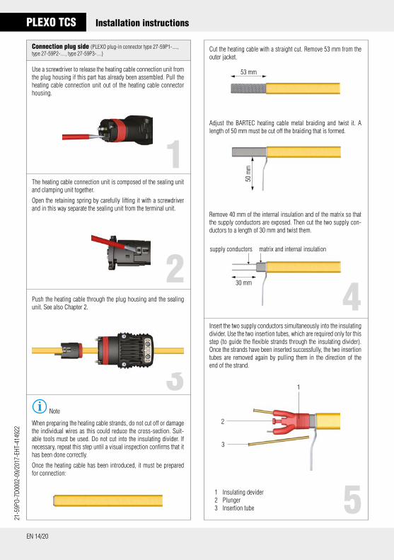
Connection plug side (PLEXO plug-in connector type 27-59P1-...., type 27-59P2-...., type 27-59P3-....)
5
Use a screwdriver to release the heating cable connection unit from the plug housing if this part has already been assembled. Pull the heating cable connection unit out of the heating cable connector housing.
Cut the heating cable with a straight cut. Remove 53 mm from the outer jacket.
Adjust the BARTEC heating cable metal braiding and twist it. A length of 50 mm must be cut off the braiding that is formed.
Insert the two supply conductors simultaneously into the insulating divider. Use the two insertion tubes, which are required only for this step (to guide the flexible strands through the insulating divider). Once the strands have been inserted successfully, the two insertion tubes are removed again by pulling them in the direction of the end of the strand.
The heating cable connection unit is composed of the sealing unit and clamping unit together.
Open the retaining spring by carefully lifting it with a screwdriver and in this way separate the sealing unit from the terminal unit.
Push the heating cable through the plug housing and the sealing unit. See also Chapter 2.
Note
When preparing the heating cable strands, do not cut off or damage the individual wires as this could reduce the cross-section. Suit-able tools must be used. Do not cut into the insulating divider. If necessary, repeat this step until a visual inspection confirms that it has been done correctly.
Once the heating cable has been introduced, it must be prepared for connection:
2
3
4
1 Insulating devider2 Plunger3 Insertion tube
53 mm
50 m
m
2
3
1
Remove 40 mm of the internal insulation and of the matrix so that the supply conductors are exposed. Then cut the two supply con-ductors to a length of 30 mm and twist them.
30 mm
supply conductors matrix and internal insulation

21-5
9PO-
7D00
02-0
9/20
17-E
HT-4
1492
2
EN 15/20ReservationTechnical data subject to change without notice. Changes, errors and misprints may not be used as a basis for any claim for damages.
6
Push the insulating divider as far as it will go onto the heating ca-ble. After that, by pressing in the plunger, seal the heating cable matrix with insulating gel.
Take care when connecting the conductors at the clamping unit that the insulating divider is in the correct position relative to the clamp-ing unit and the sealing unit. The colour markings on the individual assemblies will help here.
Make sure the sliding elements in the individual terminals are in the OPEN position.
7
8
Sliding element in the CLOSED position
Sliding element in the OPEN position.
9
11
Insert the two pre-assembled heating cable supply conductors into the holes in the external terminals. Always insert the twisted protec-tive braiding into the central terminal. Look through the inspection holes on the opposite side to check if the strands are positioned correctly.
Push the sealing unit and the clamping unit carefully together until the retaining spring locks into place.
Push the connection unit back into the housing until it audibly clicks into place in the housing. Use the guiding devices on both sides and, while inserting, press against the clamping unit in the direction of the cable entry on the enclosure.
10
The strands must be inspected visually to see if they have been introduced through the cage clamp terminals inside. Push the sliding elements for the individual supply conductor terminals from the OPEN position into the CLOSED position.
The screw heads in the housing on the socket side must be com-pletely visible after locking into place. Never remove or loosen the two screws inside the enclosure.
Close the strain relief by tightening the strain-relief screws evenly with a torque of 1.2 Nm.
green point

21-5
9PO-
7D00
02-0
9/20
17-E
HT-4
1492
2PLEXO TCS Installation instructions
EN 16/20
1
Connection socket side (PLEXO plug-in connector type 27-59P2-....)
4
Use a screwdriver to release the heating cable connection unit socket from the plug housing if this part has been assembled already. Pull the heating cable connection unit socket out of the heating cable plug housing.
Cut the heating cable with a straight cut. Remove 53 mm of the outer jacket.
Adjust the metal braiding on the BARTEC heating cables and twist it. A length of 50 mm must be cut off the braiding that is formed.
Insert the two supply conductors simultaneously into the insulating divider. Use the two insertion tubes, which are needed only for this step (to guide the flexible strands through the insulating divider). Once the conductors have been inserted correctly, pull off the two insertion tubes again in the direction of the strand end.
The heating cable connection unit is composed of the sealing unit and clamping unit together.
Open the retaining spring by carefully raising it with a screwdriver and in this way separate the sealing unit from the clamping unit.
Push the heating cable through the plug housing and the sealing unit.
Note
When preparing the heating cable strands, the individual wires must not be cut off/damaged in case that would reduce the cross-section. Use suitable tools. Do not cut into the insulating di-vider. If necessary, repeat the step until a visual inspection confirms that it has been done properly.
Once the heating cable has been inserted, it must be prepared for connection:
23
1 Insulating devider2 Plunger3 Insertion tube
53 mm
50 m
m
2
3
1
Remove 40 mm of the internal insulation and of the matrix so that the supply conductors are exposed. Then cut the two supply con-ductors to a length of 30 mm and twist them.
30 mm
supply conductors matrix and internal insulation

21-5
9PO-
7D00
02-0
9/20
17-E
HT-4
1492
2
EN 17/20ReservationTechnical data subject to change without notice. Changes, errors and misprints may not be used as a basis for any claim for damages.
5
Push the insulating divider as far as it will go onto the heating ca-ble. Then, press in the plunger to seal the heating cable matrix with insulating gel.
When connecting the conductors to the terminal unit, make sure that the insulating divider is in the correct position relative to the clamping unit and sealing unit. The colour markings on the indi-vi-dual assemblies will help you with this.
Make sure the sliding elements in the individual terminals are in the OPEN position.
6
7
Sliding element in the CLOSED position
Sliding element in the OPEN position.
8
Push the sealing unit and clamping unit together carefully until the retaining spring locks into place.
Push the connection unit back into the housing until it audibly clicks into place in the housing. Use the guiding devices on both sides and press against the clamping unit while inserting in the direction of the cable entry on the housing.
The screw heads in the housing on the socket side must be com-pletely visible after the latching. Never remove or loosen the two screws inside the enclosure.
Close the strain relief by tightening the strain relief screws evenly with a torque of 1.2 Nm.
Close the PLEXO plug-in connector (PLEXO plug-in connector type 27-59P.-....)
The PLEXO plug-in connector assembly is identical for all types.
Bring the plug side (plug housing) and the socket side (socket housing) or, as the case may be, the end termination housing as closely together as possible.
Close the safety interlock by using the hex key to tighten the hous-ing screws with a torque of 0.5 Nm.
Insert the two pre-assembled supply conductors for the heating cable into the holes in the external terminals. The twisted protective braiding must be inserted into the middle terminal always. Look through the inspection holes on the opposite side to see if the strands are positioned correctly.
The strands must be inspected visually. Make sure they have been inserted through the cage clamp terminals inside. Push the sliding elements for the individual supply conductor terminals from the OPEN position into the CLOSED position.
yellow point

21-5
9PO-
7D00
02-0
9/20
17-E
HT-4
1492
2PLEXO TCS Installation instructions
EN 18/20
8. Commissioning
Before commissioning, the acceptance test documentation must be drawn up as described in Chapter 9.
Note
The PLEXO TCS heating system´s serial number must be entered permanently with a suitable pen onto the “PLEXO TCS Heating sys-tem“ marking areas (see Chapter 5.3).
The commissioning of the heating system including the application of the serial number must be done either by an authorized person, a qualified specialist or an electrician. As the manufacturer, BARTEC can assign this responsibility to a third party.
9. PLEXO TCS Heating System Acceptance Test Documentation
9.1 General Points
As a supplement to the installation, the acceptance test report relative to the respective PLEXO TCS system must be created by the installer. With the aid of the (design) documentation the data relevant for explosion protection (e.g. parameters, temperature class, ambient temperature range etc.) is determined within the scope of the system possibilities and documented. This must be kept and made accessible for servicing purposes by the owner/managing operator throughout the entire service life of the heating circuits.
9.2 Heating System Acceptance Test PLEXO TCS
For claims under guarantee is essential to submit a correctly and fully completed acceptance report.The acceptance report can be found in the middle of this installation instruction.
10. Service address
BARTEC GmbH Max-Eyth-Str. 16 97980 Bad Mergentheim Germany Phone: +49 7931 597 0 Fax: +49 7931 597 183 info.bartec.de www.bartec.de
7. Maintenance, Service
Note
The following must be observed when replacing the supply cable or heating cables after commissioning: the sealing used for the supply cable and/or the sealing(s) for the heating cable(s) and the insulating divider(s) affected must be replaced. The necessary spare parts are avail-able as an optional service kit no. 05-0091-0203.
Note
The insulation gel is applied with a brush.
The sealings located in the sealing unit (supply cable, heating ca-ble, heating cable splice) must be removed completely first and the inside must be cleaned.
Apply a bead, at least 5 mm in diameter, of the insulating gel included in the scope of supply to the insides. Then distribute the grease evenly on the sealing area.
Once the sealing included in the scope of supply has been in-sert-ed into the connection or heating cable part, the sealing must be greased too. For this purpose two beads of the same size must be applied. These must be distributed evenly onto the sealing lips.
The quantity to be applied and also the manner of doing so is inde-pendent of the sealings located in the service kit and must always be done as described here therefore.
Replacing the sealing cable entry on the socket side/plug side (PLEXO plug-in connector type 27-59P.-....)
Connection part Insulating gel Heating part
sealing for connection
sealing for heating cable

21-5
9PO-
7D00
02-0
9/20
17-E
HT-4
1492
2
EN 19/20ReservationTechnical data subject to change without notice. Changes, errors and misprints may not be used as a basis for any claim for damages.
11. Declaration of Conformity

21-5
9PO-
7D00
02-0
9/20
17-E
HT-4
1492
2
Max-Eyth-Str. 16 97980 Bad Mergentheim
Phone: +49 7931 597 0 Fax: +49 7931 597 494
[email protected] www.bartec.de
BARTEC GmbHGermany