pl/ii halogen to led plow light update kits dual wire
TRANSCRIPT

72558, 72559, 72560Halogen to LED Plow Light Update Kits
Parts List and Installation Instructions
A DIVISION OF DOUGLAS DYNAMICS, LLC
November 25, 2019Lit. No. 74038, Rev. 02
CAUTIONRead this document before installing the harness kit.
CAUTIONSee your sales outlet/website for specifi c vehicle application recommendations before installation. The online selection system has specifi c vehicle and snowplow requirements.

Lit. No. 74038, Rev. 02 2 November 25, 2019
72558, 72559, 72560
PARTS LIST
LED Plow Light Kits
Part Description
Qty
Plow VehiclePlow & Vehicle
72559 72558 72560LED Headlamp Kit (pair) 1
39901 LED Headlamp (DS) 139902 LED Headlamp (PS) 172546 Vehicle Lighting Harness – 16-Pin, LED 1 172548 Harness Assembly – Plow Lighting – 16-Pin, LED 1 172565 Headlamp Control Module (HCM) 1 172550 Cable Assembly – HCM 1 172552 Wire Assembly – EdgeView™ Lights 1 172643 Adapter, Dual-Wire, HCM – 10-Pin 1 172512 Cover, LED Harness Connector (pkg of 2) 1 172463 Cable Boot 1 169915 Plug Cover 1 1
– Reclosable Fasteners 4 4– Cable Tie, 15", Black 10 10 10

Lit. No. 74038, Rev. 02 3 November 25, 2019
72558, 72559, 72560
SAFETY DEFINITIONS
NOTE: Indicates a situation or action that can lead to damage to your snowplow and vehicle or other property. Other useful information can also be described.
FUSES
The snowplow electrical and hydraulic systems contain several automotive-style fuses. If a problem should occur and fuse replacement is necessary, the replacement fuse must be of the same type and amperage rating as the original. Installing a fuse with a higher rating can damage the system and could start a fi re. Fuse Replacement, including fuse ratings and locations, is located in the Maintenance section of the Owner's Manual.
BATTERY SAFETY
CAUTIONIndicates a potentially hazardous situation that, if not avoided, may result in minor or moderate injury. It may also be used to alert against unsafe practices.
TORQUE CHART
CAUTIONRead instructions before assembling. Fasteners should be fi nger tight until instructed to tighten according to the torque chart. Use standard methods and practices when attaching snowplow, including proper personal protective safety equipment.
WARNINGIndicates a potentially hazardous situation that, if not avoided, could result in death or serious personal injury.
CAUTIONBatteries normally produce explosive gases, which can cause personal injury. Therefore, do not allow fl ames, sparks, or lit tobacco to come near the battery. When charging or working near a battery, always cover your face and protect your eyes, and also provide ventilation.• Batteries contain sulfuric acid, which burns
skin, eyes, and clothing.• Disconnect the battery before removing or
replacing any electrical components.
1/4-20 109 1541/4-28 121 1715/16-18 150 2125/16-24 170 2403/8-16 269 3763/8-24 297 4207/16-14 429 6067/16-20
9/16-129/16-185/8-115/8-183/4-103/4-167/8-97/8-14 474 669
644 9091-81-12 704 995
1/2-131/2-20
11.913.724.627.343.6
26.953.393148
49.469.877.9
106.4120.0
8.49.717.419.230.835.049.455.275.385.0
M6 x 1.00
M12 x 1.75
M8 x 1.25
M14 x 2.00
M10 x 1.50M27 x 3.00
M22 x 2.50
M30 x 3.50
M24 x 3.00
M20 x 2.5011.119.538.567107
7.761377811391545
4504285627961117
M33 x 3.50M36 x 4.00
21012701
14681952
325
M16 x 2.00 231167M18 x 2.50 318222
Recommended Fastener Torque Chart
Size SizeTorque (ft-lb)
Grade5
Grade8
Metric Fasteners Class 8.8 and 10.9
These torque values apply to fastenersexcept those noted in the instructions.
Torque (ft-lb)Grade
5Grade
8
Size SizeTorque (ft-lb)
Class8.8
Class10.9
Torque (ft-lb)Class
8.8Class10.9
Inch Fasteners Grade 5 and Grade 8

Lit. No. 74038, Rev. 02 4 November 25, 2019
72558, 72559, 72560
HCM Vehicle Battery Cable Installation
NOTE: When instructed, make all snowplow battery cable connections to the auxiliary battery, if vehicle is so equipped.
NOTE: Use dielectric grease on all electrical connections to prevent corrosion. Fill receptacles and lightly coat ring terminals before assembly.
1. Turn OFF the vehicle ignition.
2. Disconnect both the NEGATIVE (–) and the POSITIVE (+) battery cables from the vehicle battery.
3. Route the supplied HCM vehicle battery cable from the battery to the 2-position mating connector on the HCM vehicle lighting harness, avoiding any sharp edges and hot or moving parts.
CAUTIONBatteries normally produce explosive gases, which can cause personal injury. Therefore, do not allow fl ames, sparks, or lit tobacco to come near the battery. When charging or working near a battery, always cover your face and protect your eyes, and also provide ventilation.• Batteries contain sulfuric acid, which burns
skin, eyes, and clothing.• Disconnect the battery before removing or
replacing any electrical components.
INSTALLATION INSTRUCTIONS
LED Plow Light Vehicle-Side Dual Wire Installation
NOTE: Prior to installing the vehicle-side LED wiring, confi rm that the previously installed halogen plow lighting vehicle-side wiring is functioning correctly.
Headlamp Control Module (HCM) Mounting
Locate a fl at surface within the engine compartment of the vehicle near the isolation module. The fi re wall, fender well, or radiator shroud are possible mounting locations. If a suitable fl at surface is not accessible, cable tie the HCM to existing brackets or harnessing.
Mount the HCM so that the harness connections are wire side down.
NOTE: If possible, mount the HCM in an area that is protected from road splash.
Reclosable fastener strips and/or cable ties are supplied for mounting the HCM. When using reclosable fastener strips, the mounting surface must be free of dirt and grease.
CableTies (4)
Reclosable FastenerStrips
Headlamp Control Module(bottom view)

Lit. No. 74038, Rev. 02 5 November 25, 2019
72558, 72559, 72560
PLUG COVER INSTALLATION
Stretch the rectangular opening of the plug cover strap over the end of the HCM vehicle lighting harness. Place the plug cover over the molded plug whenever the snowplow is not in use.
HCM Vehicle Lighting Harness Installation
1. Route harnesses around or through the radiator bulkhead to the HCM.
2. Make the following connections:
• 2-position connector from the vehicle lighting harness to the matching 2-position connector from the vehicle cable assembly
• Vehicle lighting harness to position "Y" on the HCM.
NOTE: Single-pin connector from the LED vehicle lighting harness will not be required on a dual-wire system.
3. Route the red wire from the vehicle lighting harness to the stud on the HCM.
4. Remove the protective plastic domed nut and the top brass nut from the HCM stud. Install the red wire ring terminal on the stud and remaining brass nut. Reinstall the top brass nut and tighten to 25.9 in-lb. Reinstall the protective plastic domed nut. (See illustration below.)
Molded Plug
Plug Cover
Red Wire Ring Terminal(from vehicle lighting harness)
Domed Nut
Brass Nuts
Headlamp Control Module (HCM)

Lit. No. 74038, Rev. 02 6 November 25, 2019
72558, 72559, 72560
HC
M to
Is
olat
ion
Mod
ule
Har
ness
Ass
embl
y
Plow
Lig
hts
Plow
Li
ghtin
g H
arne
ss
Vehi
cle
Con
trol
Har
ness
Vehi
cle
Bat
tery
Cab
le
Vehi
cle
Cab
leA
ssem
bly
Edge
View
™
Wire
Ass
embl
y
Turn
Sig
nal
Con
figur
atio
nPl
ug
15A
Fus
es
Ford
SD
Qua
d Li
ght
Rel
ay E
nabl
e Pl
ug &
Cov
er
25A
Fus
e
10A
Fus
es
200A
Fus
e an
d H
olde
r
To Snowplow Control
To S
witc
hed
Acc
esso
ry
YEL
RED
Edge
View
W
ire
RA
M E
nabl
e W
ire (7
-wire
sy
stem
onl
y)
ORN YEL
Edge
View
En
able
Jum
per
Bat
tery
*
Vehi
cle
Ligh
ting
Har
ness
(16-
pin)
Vehi
cle
Ligh
ting
Har
ness
(11-
pin)
lnstall withwires down.
TYPICAL LED PLOW LIGHT, HEADLAMP CONTROL MODULE (HCM),AND HARNESS DIAGRAM
NOTE: Plug covers shall be used whenever snowplow is disconnected.
* NO
TE: N
ot a
ll gr
ound
wire
con
nect
ions
are
to th
e N
EGAT
IVE
(–)
batte
ry te
rmin
al. S
ome
appl
icat
ions
requ
ire N
EGAT
IVE
(–) c
able
s to
be
conn
ecte
d to
the
vehi
cle
chas
sis
grou
ndin
g st
ud. R
efer
to y
our H
arne
ss
Kit
3-Po
rt Is
olat
ion
Mod
ule
Ligh
t Sys
tem
Inst
alla
tion
Inst
ruct
ions
for t
he
prop
er b
atte
ry c
onne
ctio
ns fo
r you
r spe
cifi c
veh
icle
app
licat
ion.

Lit. No. 74038, Rev. 02 7 November 25, 2019
72558, 72559, 72560
TYPICAL RAM 7-WIRE SYSTEM'S LED PLOW LIGHT, HEADLAMP CONTROLMODULE (HCM), AND HARNESS DIAGRAM
ORANGEW
HT/
BR
N(P
AR
K)
From
Veh
icle
BC
M(B
ody
Con
trol
Mod
ule)
Bat
tery
*
HC
M to
Is
olat
ion
Mod
ule
Har
ness
Ass
embl
y
Plow
Lig
hts
Plow
Li
ghtin
g H
arne
ss
Vehi
cle
Ligh
ting
Har
ness
(16-
pin)
Vehi
cle
Con
trol
Har
ness
Vehi
cle
Ligh
ting
Har
ness
(11-
pin)
Vehi
cle
Bat
tery
Cab
le
Vehi
cle
Cab
leA
ssem
bly
Edge
View
™
Wire
Ass
embl
y
Edge
View
En
able
Jum
per
Turn
Sig
nal
Con
figur
atio
nPl
ug
15A
Fuse
s
Splic
e
Edge
View
W
ireFo
rd S
D Q
uad
Ligh
t R
elay
Ena
ble
Plug
& C
over
RA
M E
nabl
e W
ire (7
-wire
sy
stem
onl
y)
25A
Fus
e
10A
Fus
es
200A
Fus
e an
d H
olde
r
To Snowplow Control
To S
witc
hed
Acc
esso
ry
YEL
RED
ORANGE YEL
lnstall withwires down.
* NO
TE: N
ot a
ll gr
ound
wire
con
nect
ions
are
to th
e N
EGAT
IVE
(–)
batte
ry te
rmin
al. S
ome
appl
icat
ions
requ
ire N
EGAT
IVE
(–) c
able
s to
be
conn
ecte
d to
the
vehi
cle
chas
sis
grou
ndin
g st
ud. R
efer
to y
our H
arne
ss
Kit
3-Po
rt Is
olat
ion
Mod
ule
Ligh
t Sys
tem
Inst
alla
tion
Inst
ruct
ions
for t
he
prop
er b
atte
ry c
onne
ctio
ns fo
r you
r spe
cifi c
veh
icle
app
licat
ion.
NOTE: Plug covers shall be used whenever snowplow is disconnected.

Lit. No. 74038, Rev. 02 8 November 25, 2019
72558, 72559, 72560
HCM TO ISOLATION MODULE HARNESS INSTALLATION
NOTE: Ford Super Duty: 2-pin relay enable plug on the LED vehicle lighting harness will not be required on dual-wired vehicles.
NOTE: RAM 7-Wire System: Orange wire on the LED vehicle lighting harness will need to be connected to the orange and WHT/BRN wires on the original halogen system wiring.
1. Remove the 10-pin connector from port A of the isolation module.
2. Make the following connections:
• 10-pin connector from the dual-wire harness into port A on the isolation module
• 10-pin connector that was removed from port A of the isolation module into the mating 10-pin connector on the dual-wire harness
• 8-position connector to port X of the HCM.
3. Cable tie harnesses as needed, away from any sharp, hot, or moving parts.
BATTERY CONNECTIONS
NOTE: Cable tie cable assemblies and control and lighting harnesses away from any sharp edges and hot or moving parts.
NOTE: Follow OEM battery cable connection recommendations when attaching to the battery.
Battery connections vary depending on your application. Refer to your Harness Kit 3-Port Isolation Module Light System Installation Instructions for the proper battery connections for your specifi c vehicle application.
NOTE: Not all ground wire connections are to the NEGATIVE (–) battery terminal. Some applications require NEGATIVE (–) cables to be connected to the vehicle chassis grounding stud.

Lit. No. 74038, Rev. 02 9 November 25, 2019
72558, 72559, 72560
CHANGING BLADE-EDGE ILLUMINATION MODE
On snowplows equipped with LED headlamps, the EdgeView™ technology feature off ers three modes for blade-edge illumination. The factory default setting is ON.
To change the blade-edge illumination mode, remove the cover from the fuse holder located near the "Y" port of the headlamp control module installed in the vehicle engine compartment.
Remove the jumper fuse from the fuse holder and re-insert it in the desired mode position as shown below. Replace the fuse holder cover.
HEADLAMPCONTROL MODULE
Fuse Holder and Cover
Headlamp Control Module
Default – ON:Blade edge lights illuminate when plow has power.
FLT: Blade edge lights illuminate when blade is in FLOAT mode.
OFF: Blade edge lights disabled.
Jumper Fuse
PLOW-SIDE EdgeView LIGHTING CONNECTIONS
The EdgeView Float (FLT) mode activation function will require a second plow-side electrical connection.
1. On the plow-side LED lighting harness, locate the yellow wire cable tied to the body of the harness near the "Y" section.
2. Strip the end of the yellow wire and insert stripped wire end into the pre-installed insulated butt connector on the supplied EdgeView wire assembly.
3. Crimp the connection and heat seal the insulated splice.
4. Remove the plow hydraulic unit cover. Route the EdgeView wire assembly along the plow structure to the plow hydraulic unit, and cable tie wires as needed.
5. Locate the solenoid on the plow hydraulic unit that is activated during the plow Lower/Float function. Refer to the Mechanic's Guide or snowplow manufacturer's website for further information.
6. Plug the bullet terminal on the end of the supplied EdgeView wire assembly into the receptacle on the corresponding solenoid wire. If a receptacle is not found on the correct solenoid wire, remove the bullet terminal from the EdgeView wire assembly and splice the end of the EdgeView wire into the correct solenoid wire.
7. Cable tie extra wire length to the snowplow assembly and reinstall the hydraulic unit covers.
NOTE: EdgeView light will turn ON or OFF approximately 5 seconds after EdgeView Mode is activated or canceled.

Lit. No. 74038, Rev. 02 10 November 25, 2019
72558, 72559, 72560
LED HEADLAMP HARDWARE INSTALLATION INSTRUCTIONS
1. Park the vehicle on a smooth, level, hard surface, such as concrete. Lower the blade to the ground, and turn the control OFF. Disconnect the snowplow from the vehicle, or turn the vehicle ignition to the "OFF" position and remove the key.
2. Place a headlamp swivel on the light bar, aligning it with the headlamp attachment points.
3. Insert the two headlamp posts through the two holes in the swivel and light bar. Make sure to install the headlamp on the correct end of the light bar (i.e., passenger-side headlamp on the passenger's side of the bar).
CAUTIONRead this document before installing the LED headlamp hardware mounting kit.
CAUTIONUse standard methods and practices when attaching snowplow and installing accessories, including proper personal protective safety equipment.
4. On the headlamp post passing through the slot, install a 1/2" rubber washer, 1/2" fl at washer, 1/2" lock washer, and 1/2" hex nut (in that order) and hand tighten.
5. On the headlamp post passing through the hole, install a 1/2" lock washer and 1/2" hex nut. Hand tighten the fasteners.
HeadlampSwivel
1/2" RubberWasher
1/2" FlatWasher 1/2" Lock
Washers
1/2" Hex Nuts
Slot Hole

Lit. No. 74038, Rev. 02 11 November 25, 2019
72558, 72559, 72560
6. Follow the Snowplow Headlamp Beam Aiming Instructions (Lit. No. 27769) to achieve the correct visual aim. Once the headlamps are correctly aimed, tighten the headlamp fasteners to 22 ft-lb (30 N·m).
7. If not already assembled, form the two halves of the harness plug guard around the end of the harness and secure with cable ties. Tighten and trim the ends.
8. Attach the harness to the rear of the headlamp.
9. Insert a cable tie in the anchor hole in the back of the headlamp.
Cable Ties
Anchor Hole
Cable Tie
10. Pass the harness over the cable tie and secure. Tighten and trim the ends.
Lit. No. 74038, Rev. 02 12 November 25, 2019
72558, 72559, 72560
Copyright © 2019 Douglas Dynamics, LLC. All rights reserved. This material may not be reproduced or copied, in whole or in part, in any printed, mechanical, electronic, fi lm, or other distribution and storage media, without the written consent of the company. Authorization to photocopy items for internal or personal use by the company's outlets or snowplow owner is granted.
The company reserves the right under its product improvement policy to change construction or design details and furnish equipment when so altered without reference to illustrations or specifi cations used. This equipment manufacturer or the vehicle manufacturer may require or recommend optional equipment for snow removal. Do not exceed vehicle ratings with a snowplow. The company off ers a limited warranty for all snowplows and accessories. See separately printed page for this important information. The following is an unregistered (™) trademark of Douglas Dynamics, LLC: EdgeView™.
Printed in U.S.A.
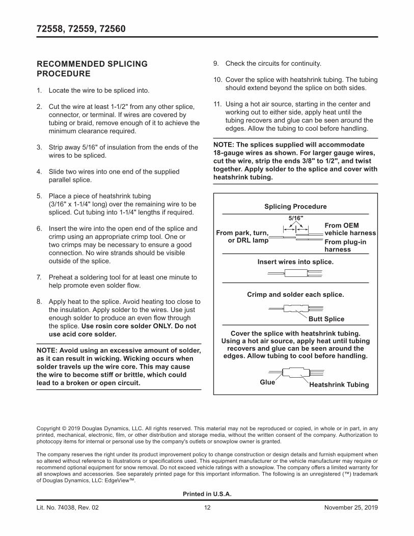
9. Check the circuits for continuity.
10. Cover the splice with heatshrink tubing. The tubing should extend beyond the splice on both sides.
11. Using a hot air source, starting in the center and working out to either side, apply heat until the tubing recovers and glue can be seen around the edges. Allow the tubing to cool before handling.
NOTE: The splices supplied will accommodate 18-gauge wires as shown. For larger gauge wires, cut the wire, strip the ends 3/8" to 1/2", and twist together. Apply solder to the splice and cover with heatshrink tubing.
Crimp and solder each splice.
From OEMvehicle harnessFrom plug-inharness
Splicing Procedure
Butt Splice
5/16"
Insert wires into splice.
From park, turn,or DRL lamp
Cover the splice with heatshrink tubing.Using a hot air source, apply heat until tubing
recovers and glue can be seen around theedges. Allow tubing to cool before handling.
Heatshrink TubingGlue
RECOMMENDED SPLICING PROCEDURE
1. Locate the wire to be spliced into.
2. Cut the wire at least 1-1/2" from any other splice, connector, or terminal. If wires are covered by tubing or braid, remove enough of it to achieve the minimum clearance required.
3. Strip away 5/16" of insulation from the ends of the wires to be spliced.
4. Slide two wires into one end of the supplied parallel splice.
5. Place a piece of heatshrink tubing (3/16" x 1-1/4" long) over the remaining wire to be spliced. Cut tubing into 1-1/4" lengths if required.
6. Insert the wire into the open end of the splice and crimp using an appropriate crimp tool. One or two crimps may be necessary to ensure a good connection. No wire strands should be visible outside of the splice.
7. Preheat a soldering tool for at least one minute to help promote even solder fl ow.
8. Apply heat to the splice. Avoid heating too close to the insulation. Apply solder to the wires. Use just enough solder to produce an even fl ow through the splice. Use rosin core solder ONLY. Do not use acid core solder.
NOTE: Avoid using an excessive amount of solder, as it can result in wicking. Wicking occurs when solder travels up the wire core. This may cause the wire to become stiff or brittle, which could lead to a broken or open circuit.