plm 1.0 riduttori paralleli - pendolari lunghi shaft ... · ct17igbd2.1 f1 f 1.0 riduttori...
TRANSCRIPT

CT17IGBD2.1 F1
F
1.0 RIDUTTORI PARALLELI - PENDOLARI LUNGHISHAFT MOUNTED AND PARALLEL SHAFT GEARBOXES LONG VERSIONFLACH AUFSTECKGETRIEBE GESTRECKTE VERSION
PLM
PLR
PLC
Pag.PageSeite
1.1 Caratteristiche tecniche Technical characteristics Technische Eigenschaften F2
1.2 Designazione Designation Bezeichnungen F2
1.3 Versioni Versions Ausführungen F5
1.4 Lubrificazione Lubrication Schmierung F6
1.5 Carichi radiali e assiali Axial and overhung loads Radiale und Axiale Belastungen F7
1.6 Prestazioni riduttori Gearboxes performances Leistungen der Getriebe F8
1.7 Prestazioni motoriduttori Gearmotors performances Leistungen der Getriebemotoren F13
1.8 Dimensioni Dimensions Abmessungen F18
1.9 Accessori Accessories Zubehör F30
1.10 Linguette Keys Paßfedern F31

CT17IGBD2.1F2
1.1 Technical characteristics 1.1 Technische Eigenschaften1.1 Caratteristiche tecniche
1.2 Designation1.2 Designazione 1.2 Bezeichnung
Grand.Size
Größe
TipoTypeTyp
*1 * 2 *3 ir IECTipoTypeTyp
Grand.Size
Größe
LunghezzaLenghtLänge
Esempio / Example / Beispiel
PLM
80 (B5)80 (B14)
....PLM 25 1: 23.8 80 B525 — — — —
B
C Veditabelle
prestazioni45 F1 N
TTA....H
56....
315
A....
ML
PLM 45 - 1:28.7 -T 71 A 4 B5
D
Diametro
foroopzional
e
Seeperformance tables
65 DB
FA CDSiehe
Leistungs-tabellen
PLR
85 FD
Optionalhollowshaft
diameter
PLR 65 F1 1: 138.8FDB S
FB
95
TTA....H
56....
315
A....
MLPLCPLC 85 - 1:43.7 -T 80 B 4 B5
Optionaler
Hohlwellen
durchmesser
Designazione MotoriDesignation MotorsBezeichnung Motoren
CT18IGBD1
La progettazione di questi riduttori è stataimpostata su una struttura monolitica par-ticolarmente rigida che permette l’applica-zione di elevati carichi.
I riduttori – motoriduttori paralleli o pendo-lari possono essere a 3 o 4 stadi.
The design of this series of gearboxes hasbeen set up on a very rigid monolithicstructure enabling the application of heavyloads.
Parallel shaft gearboxes or shaft mountedgearboxes and motorgearboxes have 3 or 4stages.
Der Entwicklung dieser Getriebeserie wurdeeine monolithische Gehäusestruktur zugru-nde gelegt.
Deren kompakte Bauweise sowie diebesonders hohe Stabilität ermöglichenauch höchste Belastungen.
Specification: Spezifikationen:Specifiche:
• [*1] Output shaft:No indication = shaft with keyway;B = Double integral output shaftC = hollow shaft with shrink diskN = Output shaftD = Splined output shaftDB =Double splined shaftCD =Splined hollow shaftFD = Broached flangeFDB =Double broached flange
• [*1] Abtriebswelle:Keine Angabe = Hohlwelle mit PaßfedernutB = Doppeltem IntegralwelleC = Hohlwelle mit SchrumpfscheibeN = Holwelle mit WellenendeD = Abtriebswelle mit KeilendeDB = Doppelseitig verzahnte WelleCD =Verzahnte HohlwelleFD = Geräumtem FlanschFDB =Geraeumter Doppelflansch
• [*1] Albero uscita:Nessuna indicazione = albero forato;B = albero bisporgente integraleC = albero forato con calettatoreN = Sporgente IntegraleD = Sporgente ScanalatoDB = Bisporgente integrale ScanalatoCD = Albero forato ScanalatoFD = Flangia brocciataFDB = Flangia brocciataBisporgente

CT17IGBD2.1 F3
F
1.2 Designation1.2 Designazione 1.2 Bezeichnung
GrandezzaSize
Größe
[*3]
Albero foratoShaft with keyway
Holwelle mitPaßfedernut
Albero forato concalettatore
Hollow shaft with shrinkdisc
Holwelle mitSchrupmfscheibe
SporgenteIntegrale
Output shaftHolwelle mitWellenende
Bisporgenteintegrale
Double outputshaft
Holwelle mitDoppeltemWellenende
SporgenteScanalato
Splined outputshaft
Abtriebswellemit Keilende
Bisporgenteintegrale
ScanalatoDouble splined
shaftDoppelseitig
verzahnteWelle
Alberoforato
ScanalatoSplined
hollow shaftVerzahnteHohlwelle
FlangiabrocciataBroached
flangeGeräumtem
Flansch
Flangiabrocciata
BisporgenteDouble
broachedflangeGeraeu
mterDoppelflansch
Standard Optional Standard OptionalStandardOptional
.
- ... C C... N B D DB CD FD FDB
25 � 20� 24�19
� 20
-
� 20 Standard - - -
45 � 30 � 25 � 30 � 30 StandardDIN 548235 x 31
DIN 548228 x 25 -
65 � 35 � 30 � 35 � 35 StandardDIN 548240 x 36
DIN 548235 x 31
DIN 548240 x 36
85 � 45� 50� 40
� 45 � 45 StandardDIN 548258 x 53
DIN 548245 x 41
DIN 548258 x 53
95 � 55� 60� 50
� 55 � 55 StandardDIN 548270 x 64
DIN 548255 x 50
DIN 548270 x 64
• [*3] Mounting Shaft:No indication (standard) = on right side;S = on left side, on the opposite.
• [*3] Montageposition Welle:Keine Angabe (Standard) = rechts;S =links.
- C N D CDB DB
• [*2] Shaft diameter:See table .
• [*2] Durchmesser Abtriebswelle:S. Tabelle .• [*2] Diametro albero:
Vedi tabella .
FD FDB
• [*3] Posizione Albero:Nessuna indicazione = lato destro (standard);S = lato sinistro, montaggio dalla parteopposta (opzionale).
C
N
D
CD
FD
Albero forato con calettatoreHollow shaft with shrink disc
Holwelle mit Schrupmfscheibe
Sporgente IntegraleOutput shaft
Holwelle mit Wellenende
Sporgente ScanalatoSplined output shaft
Abtriebswelle mit Keilende
Albero forato ScanalatoSplined hollow shaftVerzahnte Hohlwelle
Flangia brocciataBroached flange
Geräumtem Flansch

CT17IGBD2.1F4
• [M1, M2, M3, M4, M5] Posizioni dimontaggio con indicazione dei tappi dilivello, carico e scarico; se nonspecificato si considera standard laposizione M6 (vedi par. 1.4).
• [T] Dispositivo antivibrante (vedi par.1.9).
• [2 o 3 o 4] Posizione della morsettieradel motore se diversa da quella standard(1).
• Montageposition [M1, M2, M3, M4, M5]mit Angabe von Entlüftung, Schaugläsernund Ablaßschraube. Wenn nicht näherspezifiziert, wird die StandardpositionM6 zugrunde gelegt (s. Abschnitt 1.4).
• [T] Gummihülse (s. par. 1.9).
• Montageposition Klemmenkasten [2, 3, 4],wenn abweichend von Standardposition[1] (für Motorgetriebe).
Altre specifiche: Further specification: Weitere Spezifikationen:
• [M1, M2, M3, M4, M5] Mounting positionwith indication of breather, level and drainplugs; if not specified, standard positionis M6 (see par. 1.4).
• [T] Rubber buffer (see par. 1.9).
• [2 o 3 o 4] Position of the motor terminalbox if different from the standard one [1](for gearmotors)
Posizione morsettieraTerminal board positionLage des Klemmenkastens
1.2 Designation1.2 Designazione 1.2 Bezeichnung

CT17IGBD2.1 F5
F
1.3 Versions 1.3 Ausführungen1.3 Versioni
Posizione morsettieraTerminal board positionLage des Klemmenkastens
PLM...(IEC)
Senso di rotazioneDirection of rotation
Drehrichtung
3 stadi/stages/stufig
PLM...(KW)
PL..(25 - 45)
PL..F..(25 - 45)
PL..(65 - 85 - 95)
PL..F.. (**)(65 - 85 - 95)
PLR...
PLC
** Le flange sono disponibili nella versione standard solo come indicato in figura.Le Flange sono tutte modulari fatta eccezione per la grandezza 65.

CT17IGBD2.1F6
1.4 Lubrication1.4 Lubrificazione 1.4 Schmierung
Carico / Breather plug / Einfüll-u. EntlüftungsschraubeLivello / Level plug / SchauglasScarico / Drain plug / Ablaßschraube
Tab. 1.1
Mounting positionsPosizioni di montaggio Montagepositionen
M5 M6M3M2 M4M1
GeneralitàSi consiglia l’uso di oli a base sintetica. (Vederea tale proposito le indicazioni riportate nelcapitolo A).Nella Tab. 1.1 sono riportati i quantitativi di olionecessari per il corretto funzionamento deiriduttori.
Prescrizioni in fase d’ordine e stato difornituraI riduttori della grandezza 25, 45, 65 sono forniticompleti di olio sintetico di viscosità ISO 320.Per questi riduttori è necessario specificare laposizione di montaggio.I riduttori nelle grandezze 85, 95 sono fornitipredisposti per lubrificazione ad olio ma privi dilubrificante il quale potrà essere fornito arichiesta.Per questi riduttori è necessario specificare laposizione di montaggio.
General informationThe use of synthetic oil is recommended (seedetails in Chapter A).Tab. 1.1 shows the quantities of oil required forcorrect parallel-shaft mounted gearboxperformance.
Ordering phase requirements and state ofsupplySize 25, 45, 65 gearbox are supplied with ISO320 viscosity synthetic oil. It is necessary tospecify mounting position of this gearbox.Size 85 and 95 . parallel - shaft mountedgearboxes are supplied pre-arranged for oillubrication but without lubricant that can berequested separately.It is necessary to specify the mounting positionwith these gearboxes.
AllgemeinesDer Einsatz von synthetischem Öl wirdempfohlen. (Siehe diesbezüglich die Hinweiseim Kapitel A).In der Tab. 1.1 werden die erforderlichenÖlfüllmengen für einen störungsfreien Betrieb
Vorgaben für die bestellung und denlieferzustandDie Getriebe in der Baugröße 25, 45, 65 wirdkomplett mit Synthetiköl mit einer Viskosität ISO320 geliefert.Für dieses Getriebe muss die Einbaulage ver-bindlich angegeben werden.Die Getriebe in den Baugrößen 85 und 95 sindbei der Lieferung für die Ölschmierung vorberei-tet, enthalten jedoch kein Schmiermittel. Dieseskann auf Anfrage geliefert werden.Für diese Getriebe muss die Einbaulageverbindlich angegeben werden.
M1M4 M5 Z3
ATTENZIONE
A) Se in fase d’ordine la posizione di montaggio èomessa, il riduttore verrà fornito con i tappipredisposti per la posizione M1.
B) Il tappo di sfiato è allegato solo nei riduttori chehanno più di un tappo olio.
C) Eventuali forniture con predisposizioni tappi diverseda quella indicata in tabella, dovranno essereconcordate.
D) Nei riduttori dove è necessario specificare laposizione di montaggio, la posizione richiesta èindicata nella targhetta del riduttore.
WARNING
A) It is necessary to specify the mounting position whenordering. If the mounting position is not specified inthe ordering phase, the gearbox supplied will haveplugs pre-arranged for position M1.
B) A breather plug is supplied only with gearboxes thathave more than one oil plug.
C) The supply of gearboxes with different plugpre-arrangements has to be agreed with themanufacturer.
D) The gearboxes that need a specific assemblingposition have the indication of it on the label of thegearbox.
ACHTUNG
A) In der Auftragsphase muss die Einbaulage verbind-lich angegeben werden. Sollte dies nicht erfolgen,wird das Getriebe mit Stopfen für die EinbaulageM1.
B) Der Entlüftungsstopfen ist lediglich bei den Getrie-ben vorhanden, die über mehr als einen Ölfüllstop-fen verfügen.
C) Lieferungen, die eine Auslegung hinsichtlich der Stopfenaufweisen, die von den Angaben in der Tabelleabweichen, müssen vorab vereinbart werden.
D) In den Getrieben in dem man die Montage Positionangeben soll, findet man die angefragte Position aufdem Typenschild des Getriebes.
* Richiedere ad Ufficio Tecnico/ Request to our Technical Dept. / Bei der Technischen Abteilung anfordern
Quantità di lubrificante / Lubricant Quantity / Schmiermittelmenge (kg)
PLMPLRPLC
Posizioni di montaggio /Mounting Positions / Einbaulagen* n°. tappi olio* No.of plugs
Anz. Ölschrauben
Posizione di montaggioMounting position
EinbaulagenM1 M2 M3 M4 M5 M6Stato di fornituraState of supplyLieferzustand
25 0.500 0.600 0.500
Riduttori forniti completi di olio sinteticoGearboxes supplied with synthetic oil
Mit Synthetiköl gefüllt gelieferte Getriebe
1 Non necessariaNot necessary
Nichterforderlich
45 1.300 * * * * 1
65 1.850 * 1.550 1.550 1.400 6NecessariaNecessary
Erforderlich
85 3.700 2.400 3.150 2.900 2.300 Riduttori predisposti per lubrificazione ad olioGearboxes supplied ready for oil
lubricationFür die Ölschmierung ausgelegte Getriebe
6
95 6.100 4.550 5.250 4.550 3.550 6

CT17IGBD2.1 F7
F
Tab. 1.3
Tab. 1.2
In Table 1.3 permissible radial loads foroutput shaft are listed (Fr2).Permissible axial load is given by thefollowing formula:
Fa2 = 0.2 x Fr2
In Tabelle 1.3 sind die Werte der zulässi-gen Radialbelastungen für die Abtriebswelle(Fr2) angegeben.Als zulässige Axialbelastung gilt:
Fa2 = 0.2 x Fr2
In Tab. 1.3 sono riportati i valori dei carichiradiali ammissibili per l’albero lento (Fr2) .Come carico assiale ammissibile contem-poraneo si ha:
Fa2 = 0.2 x Fr2
The radial loads shown in the tables areapplied on the middle of standard shaftextensions (see fig.8.14). Base of thesevalues is a service factor 1.Values for speeds that are not listed can beobtained through interpolation but it mustbe considered that Fr1 at 500 min-1 and Fr2
at 5 min-1 represent the maximum allowableloads.For radial loads which are not applied onthe middle of the shafts, the followingvalues can be calculated:
at 0.3 from extension:Frx = 1.25 x Fr1-2
at 0.8 from extension:Frx = 0.8 x Fr1-2
Bei den in der Tabelle angegebenRadialbelastungen wird eine Kraftein-wirkung auf die Mitte der Standardwelle (s.A.8.14) angenommen; außerdem wird einBetriebsfaktor 1 zugrunde gelegt. Zwischen-werte für nicht aufgeführte Drehzahlenkönnen durch Interpolation ermittelt werden.Hierbei ist jedoch zu berücksichtigen, daßFr1 bei 500 min-1 und für Fr2max bei 5 min-1
die maximal zulässigen Belastungenrepräsentieren.Ist die Einwirkung der Radialkraft nicht inder Mitte der Welle, so können diezulässigen Radiallasten folgendermaßenermittelt werden:0.3 vom Wellenabsatz entfernt:
Frx = 1.25 x Fr1-2
0.8 vom Wellenabsatz entfernt:Frx = 0.8 x Fr1-2
Should transmission movement determineradial loads on the angular shaft end, it isnecessary to make sure that resultingvalues do not exceed the ones indicated inthe tables.In Table 1.2 permissible radial load for inputshaft are listed (Fr1). Contemporary permis-sible axial load is given by the followingformula:
Fa1 = 0.2 x Fr1
Wird das Wellenende auch durchRadialkräfte belastet, so muß sicher-gestellt werden, daß die resultierendenWerte die in der Tabelle angegebenen nichtüberschreiten.In Tabelle 1.2 sind die Werte der zuläs-sigen Radialbelastungen für die Antrieb-swelle (Fr1) angegeben. Die Axialbela-stung beträgt dann:
Fa1 = 0.2 x Fr1
Quando la trasmissione del moto avvienetramite meccanismi che generano carichiradiali sull’estremità dell’albero, è neces-sario verificare che i valori risultanti noneccedono quelli indicati nelle tabelle.Nella Tab. 1.2 sono riportati i valori deicarichi radiali ammissibili per l’alberoveloce (Fr1). Come carico assiale ammis-sibile contemporaneo si ha:
Fa1 = 0.2 x Fr1
1.5 Axial and overhung load1.5 Carichi radiali e assiali 1.5 Radiale und axialeBelastungen
I carichi radiali indicati nelle tabelle si inten-dono applicati a metà della sporgenzadell’albero lento standard (vedi fig. 8.14) esono riferiti ai riduttori operanti con fattoredi servizio 1. Valori intermedi relativi avelocità non riportate possono essereottenuti per interpolazione considerandoperò che Fr1 a 500 min-1 e Fr2 a 5 min-1
rappresentano i carichi massimi consentiti.Per i carichi non agenti sulla mezzeriadell’albero lento o veloce si ha:
a 0.3 della sporgenza:Frx = 1.25 x Fr1-2
a 0.8 dalla sporgenza:Frx = 0.8 x Fr1-2
n1
[min-1]
Fr1 [N]PLR.
25/3 25/4 45/3 45/4 65/3 85/3 95/3
2800
-
430 520 6001400 550 700 800900 600 800 920500 850 1100 1300
Fr2 [N]
n2
[min-1]
PLM. - PLR. - PLC.
25 45 65 85 95
160 1300 3550 5775 8000 14000
125 1300 3750 6875 10000 16000
90 1800 4000 7000 10000 16000
60 1800 4500 7550 10600 18000
40 1800 5000 8400 11800 20000
25 2300 5000 8750 12500 20000
16 2300 5000 8750 12500 20000
10 2800 5000 8750 12500 20000
5 3000 5000 8750 12500 20000

CT17IGBD2.1F8
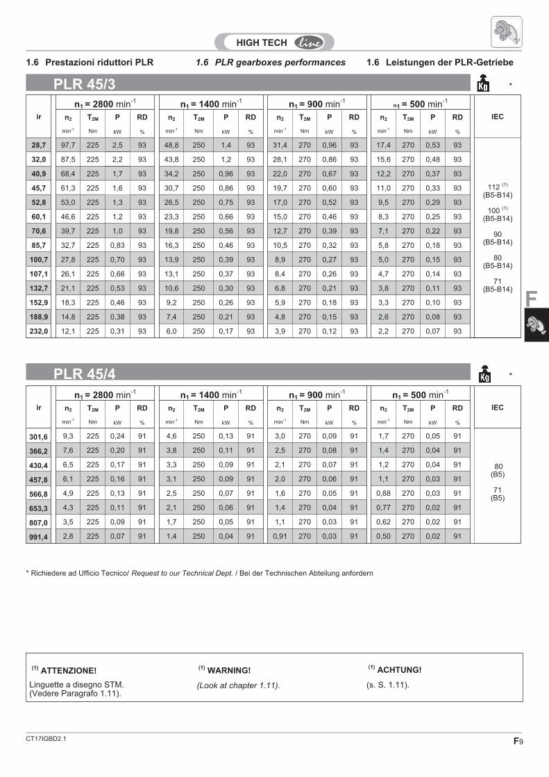
1.6 PLR gearboxes performances 1.6 Leistungen der PLR-Getriebe1.6 Prestazioni riduttori PLR
ir
n1 = 2800 min-1n1 = 1400 min-1
n1 = 900 min-1n1 = 500 min-1
IECn2 T2M P RD n2 T2M P RD n2 T2M P RD n2 T2M P RD
min-1 Nm kW % min-1 Nm kW % min-1 Nm kW % min-1 Nm kW %
17,2 162,3 90 1,64 93 81,2 100 0,91 93 52,2 110 0,64 93 29,0 110 0,36 93
80(B5-B14)
71(B5-B14)
63(B5-B14)
20,4 137,5 90 1,39 93 68,8 100 0,77 93 44,2 110 0,54 93 24,6 110 0,30 93
23,8 117,7 90 1,19 93 58,9 100 0,66 93 37,8 110 0,46 93 21,0 110 0,26 93
27,4 102,2 90 1,04 93 51,1 100 0,58 93 32,8 110 0,40 93 18,2 110 0,23 93
32,0 87,5 90 0,89 93 43,7 100 0,49 93 28,1 110 0,34 93 15,6 110 0,19 93
36,9 75,8 90 0,77 93 37,9 100 0,43 93 24,4 110 0,30 93 13,5 110 0,17 93
42,6 65,7 90 0,67 93 32,8 100 0,37 93 21,1 110 0,26 93 11,7 110 0,15 93
54,8 51,1 90 0,52 93 25,6 100 0,29 93 16,4 110 0,20 93 9,1 110 0,11 93
64,6 43,3 90 0,44 93 21,7 100 0,24 93 13,9 110 0,17 93 7,7 110 0,10 93
75,5 37,1 90 0,38 93 18,5 100 0,21 93 11,9 110 0,15 93 6,6 110 0,08 93
87,0 32,2 90 0,33 93 16,1 100 0,18 93 10,3 110 0,13 93 5,7 110 0,07 93
101,6 27,5 90 0,28 93 13,8 100 0,16 93 8,9 110 0,11 93 4,9 110 0,06 93
117,3 23,9 90 0,24 93 11,9 100 0,13 93 7,7 110 0,09 93 4,3 110 0,05 93
135,3 20,7 90 0,21 93 10,3 100 0,12 93 6,7 110 0,08 93 3,7 110 0,05 93
159,1 17,6 90 0,18 93 8,8 100 0,10 93 5,7 110 0,07 93 3,1 110 0,04 93
187,8 14,9 90 0,15 93 7,5 100 0,08 93 4,8 110 0,06 93 2,7 110 0,03 93
213,9 13,1 90 0,13 93 6,5 100 0,07 93 4,2 110 0,05 93 2,3 110 0,03 93
254,1 11,0 90 0,11 93 5,5 100 0,06 93 3,5 110 0,04 93 2,0 110 0,02 93
PLR 25/3 4.6
ir
n1 = 2800 min-1n1 = 1400 min-1
n1 = 900 min-1n1 = 500 min-1
IECn2 T2M P RD n2 T2M P RD n2 T2M P RD n2 T2M P RD
min-1 Nm kW % min-1 Nm kW % min-1 Nm kW % min-1 Nm kW %
280,1 10,0 90 0,10 91 5,0 100 0,06 91 3,2 110 0,04 91 1,8 110 0,02 91
63(B5-B14)
56(B5-B14)
327,1 8,6 90 0,09 91 4,3 100 0,05 91 2,8 110 0,03 91 1,5 110 0,02 91
377,0 7,4 90 0,08 91 3,7 100 0,04 91 2,4 110 0,03 91 1,3 110 0,02 91
440,4 6,4 90 0,07 91 3,2 100 0,04 91 2,0 110 0,03 91 1,1 110 0,01 91
508,2 5,5 90 0,06 91 2,8 100 0,03 91 1,8 110 0,02 91 1,0 110 0,01 91
586,4 4,8 90 0,05 91 2,4 100 0,03 91 1,5 110 0,02 91 0,85 110 0,01 91
689,4 4,1 90 0,04 91 2,0 100 0,02 91 1,3 110 0,02 91 0,73 110 0,01 91
813,8 3,4 90 0,04 91 1,7 100 0,02 91 1,1 110 0,01 91 0,61 110 0,01 91
927,0 3,0 90 0,03 91 1,5 100 0,02 91 1,0 110 0,01 91 0,54 110 0,01 91
1101 2,5 90 0,03 91 1,3 100 0,01 91 0,82 110 0,01 91 0,45 110 0,01 91
PLR 25/4 4.6
CT17IGBD2.1 F9
F
PLR 45/3 *
PLR 45/4 *
ir
n1 = 2800 min-1n1 = 1400 min-1
n1 = 900 min-1n1 = 500 min-1
IECn2 T2M P RD n2 T2M P RD n2 T2M P RD n2 T2M P RD
min-1 Nm kW % min-1 Nm kW % min-1 Nm kW % min-1 Nm kW %
28,7 97,7 225 2,5 93 48,8 250 1,4 93 31,4 270 0,96 93 17,4 270 0,53 93
112 (1)
(B5-B14)
100 (1)
(B5-B14)
90(B5-B14)
80(B5-B14)
71(B5-B14)
32,0 87,5 225 2,2 93 43,8 250 1,2 93 28,1 270 0,86 93 15,6 270 0,48 93
40,9 68,4 225 1,7 93 34,2 250 0,96 93 22,0 270 0,67 93 12,2 270 0,37 93
45,7 61,3 225 1,6 93 30,7 250 0,86 93 19,7 270 0,60 93 11,0 270 0,33 93
52,8 53,0 225 1,3 93 26,5 250 0,75 93 17,0 270 0,52 93 9,5 270 0,29 93
60,1 46,6 225 1,2 93 23,3 250 0,66 93 15,0 270 0,46 93 8,3 270 0,25 93
70,6 39,7 225 1,0 93 19,8 250 0,56 93 12,7 270 0,39 93 7,1 270 0,22 93
85,7 32,7 225 0,83 93 16,3 250 0,46 93 10,5 270 0,32 93 5,8 270 0,18 93
100,7 27,8 225 0,70 93 13,9 250 0,39 93 8,9 270 0,27 93 5,0 270 0,15 93
107,1 26,1 225 0,66 93 13,1 250 0,37 93 8,4 270 0,26 93 4,7 270 0,14 93
132,7 21,1 225 0,53 93 10,6 250 0,30 93 6,8 270 0,21 93 3,8 270 0,11 93
152,9 18,3 225 0,46 93 9,2 250 0,26 93 5,9 270 0,18 93 3,3 270 0,10 93
188,9 14,8 225 0,38 93 7,4 250 0,21 93 4,8 270 0,15 93 2,6 270 0,08 93
232,0 12,1 225 0,31 93 6,0 250 0,17 93 3,9 270 0,12 93 2,2 270 0,07 93
ir
n1 = 2800 min-1n1 = 1400 min-1
n1 = 900 min-1n1 = 500 min-1
IECn2 T2M P RD n2 T2M P RD n2 T2M P RD n2 T2M P RD
min-1 Nm kW % min-1 Nm kW % min-1 Nm kW % min-1 Nm kW %
301,6 9,3 225 0,24 91 4,6 250 0,13 91 3,0 270 0,09 91 1,7 270 0,05 91
80(B5)
71(B5)
366,2 7,6 225 0,20 91 3,8 250 0,11 91 2,5 270 0,08 91 1,4 270 0,04 91
430,4 6,5 225 0,17 91 3,3 250 0,09 91 2,1 270 0,07 91 1,2 270 0,04 91
457,8 6,1 225 0,16 91 3,1 250 0,09 91 2,0 270 0,06 91 1,1 270 0,03 91
566,8 4,9 225 0,13 91 2,5 250 0,07 91 1,6 270 0,05 91 0,88 270 0,03 91
653,3 4,3 225 0,11 91 2,1 250 0,06 91 1,4 270 0,04 91 0,77 270 0,02 91
807,0 3,5 225 0,09 91 1,7 250 0,05 91 1,1 270 0,03 91 0,62 270 0,02 91
991,4 2,8 225 0,07 91 1,4 250 0,04 91 0,91 270 0,03 91 0,50 270 0,02 91
1.6 PLR gearboxes performances 1.6 Leistungen der PLR-Getriebe1.6 Prestazioni riduttori PLR
(1)ATTENZIONE!
(1)WARNING!
(1)ACHTUNG!
Linguette a disegno STM.(Vedere Paragrafo 1.11).
(Look at chapter 1.11). (s. S. 1.11).
* Richiedere ad Ufficio Tecnico/ Request to our Technical Dept. / Bei der Technischen Abteilung anfordern

CT17IGBD2.1F10
PLR 65/3 *
ir
n1 = 2800 min-1n1 = 1400 min-1
n1 = 900 min-1n1 = 500 min-1
IECn2 T2M P RD n2 T2M P RD n2 T2M P RD n2 T2M P RD
min-1 Nm kW % min-1 Nm kW % min-1 Nm kW % min-1 Nm kW %
26,4 106,2 540 6,5 93 53,1 600 3,6 93 34,1 650 2,5 93 19,0 650 1,4 93
112(B5-B14)
100(B5-B14)
90(B5-B14)
80(B5-B14)
71 B5
63 B5
32,3 86,7 540 5,3 93 43,3 600 2,9 93 27,9 650 2,0 93 15,5 650 1,1 93
37,6 74,5 540 4,5 93 37,3 600 2,5 93 24,0 650 1,8 93 13,3 650 1,0 93
46,0 60,8 540 3,7 93 30,4 600 2,1 93 19,6 650 1,4 93 10,9 650 0,79 93
54,3 51,5 540 3,1 93 25,8 600 1,7 93 16,6 650 1,2 93 9,2 650 0,67 93
64,4 43,4 540 2,6 93 21,7 600 1,5 93 14,0 650 1,0 93 7,8 650 0,57 93
74,4 37,6 540 2,3 93 18,8 600 1,3 93 12,1 650 0,89 93 6,7 650 0,49 93
85,4 32,8 540 2,0 93 16,4 600 1,1 93 10,5 650 0,77 93 5,9 650 0,43 93
99,0 28,3 540 1,7 93 14,1 600 0,96 93 9,1 650 0,67 93 5,0 650 0,37 93
116,2 24,1 540 1,5 93 12,0 600 0,81 93 7,7 650 0,57 93 4,3 650 0,31 93
138,8 20,2 540 1,2 93 10,1 600 0,68 93 6,5 650 0,48 93 3,6 650 0,26 93
152,8 18,3 540 1,1 93 9,2 600 0,62 93 5,9 650 0,43 93 3,3 650 0,24 93
175,4 16,0 540 1,0 93 8,0 600 0,54 93 5,1 650 0,38 93 2,9 650 0,21 93
197,9 14,1 540 0,86 93 7,1 600 0,48 93 4,5 650 0,33 93 2,5 650 0,18 93
1.6 PLR gearboxes performances 1.6 Leistungen der PLR-Getriebe1.6 Prestazioni riduttori PLR
PLR 85/3 37
ir
n1 = 2800 min-1n1 = 1400 min-1
n1 = 900 min-1n1 = 500 min-1
IECn2 T2M P RD n2 T2M P RD n2 T2M P RD n2 T2M P RD
min-1 Nm kW % min-1 Nm kW % min-1 Nm kW % min-1 Nm kW %
23,8 117,9 720 9,6 93 58,9 800 5,3 93 37,9 850 3,7 93 21,0 850 2,0 93
132(B5-B14)
112(B5-B14)
100(B5-B14)
90(B5-B14)
80(B5-B14)
71 B5
27,5 101,7 765 8,8 93 50,8 850 4,9 93 32,7 920 3,4 93 18,2 920 1,9 93
34,5 81,2 810 7,4 93 40,6 900 4,1 93 26,1 950 2,9 93 14,5 950 1,6 93
38,7 72,3 855 7,0 93 36,1 950 3,9 93 23,2 1050 2,7 93 12,9 1050 1,5 93
43,7 64,1 900 6,5 93 32,0 1000 3,6 93 20,6 1050 2,5 93 11,4 1050 1,4 93
56,3 49,7 990 5,5 93 24,9 1100 3,1 93 16,0 1200 2,2 93 8,9 1200 1,2 93
63,9 43,8 1080 5,3 93 21,9 1200 3,0 93 14,1 1300 2,1 93 7,8 1300 1,1 93
74,0 37,8 1080 4,6 93 18,9 1200 2,6 93 12,2 1300 1,8 93 6,8 1300 1,0 93
84,9 33,0 1080 4,0 93 16,5 1200 2,2 93 10,6 1300 1,6 93 5,9 1300 0,86 93
98,0 28,6 1080 3,5 93 14,3 1200 1,9 93 9,2 1300 1,4 93 5,1 1300 0,75 93
113,5 24,7 1080 3,0 93 12,3 1200 1,7 93 7,9 1300 1,2 93 4,4 1300 0,64 93
136,8 20,5 1080 2,5 93 10,2 1200 1,4 93 6,6 1300 0,97 93 3,7 1300 0,54 93
160,0 17,5 1080 2,1 93 8,7 1200 1,2 93 5,6 1300 0,83 93 3,1 1300 0,46 93
184,6 15,2 1080 1,8 93 7,6 1200 1,0 93 4,9 1300 0,72 93 2,7 1300 0,40 93
204,1 13,7 1080 1,7 93 6,9 1200 0,93 93 4,4 1300 0,65 93 2,4 1300 0,36 93
214,0 13,1 1080 1,6 93 6,5 1200 0,88 93 4,2 1300 0,62 93 2,3 1300 0,34 93
234,0 12,0 1080 1,5 93 6,0 1200 0,81 93 3,8 1300 0,57 93 2,1 1300 0,31 93
270,0 10,4 1080 1,3 93 5,2 1200 0,70 93 3,3 1300 0,49 93 1,9 1300 0,27 93
* Richiedere ad Ufficio Tecnico/ Request to our Technical Dept. / Bei der Technischen Abteilung anfordern

CT17IGBD2.1 F11
F
PLR 95/3 55
1.6 PLR gearboxes performances 1.6 Leistungen der PLR-Getriebe1.6 Prestazioni riduttori PLR
ir
n1 = 2800 min-1n1 = 1400 min-1
n1 = 900 min-1n1 = 500 min-1
IECn2 T2M P RD n2 T2M P RD n2 T2M P RD n2 T2M P RD
min-1 Nm kW % min-1 Nm kW % min-1 Nm kW % min-1 Nm kW %
23,6 118,4 1260 16,8 93 59,2 1400 9,3 93 38,1 1524 6,5 93 21,2 1524 3,6 93
160 B5
132 B5
112 B5
100 B5
90 B5
80 B5
27,4 102,2 1350 15,5 93 51,1 1500 8,6 93 32,9 1633 6,0 93 18,3 1633 3,4 93
32,9 85,1 1440 13,8 93 42,5 1600 7,7 93 27,3 1742 5,4 93 15,2 1742 3,0 93
40,5 69,1 1530 11,9 93 34,6 1700 6,6 93 22,2 1851 4,6 93 12,3 1851 2,6 93
46,9 59,7 1620 10,9 93 29,8 1800 6,0 93 19,2 1960 4,2 93 10,7 1960 2,4 93
54,7 51,2 1800 10,4 93 25,6 2000 5,8 93 16,4 2178 4,0 93 9,1 2178 2,2 93
65,4 42,8 1890 9,1 93 21,4 2100 5,1 93 13,8 2287 3,5 93 7,7 2287 2,0 93
74,2 37,7 1935 8,2 93 18,9 2150 4,6 93 12,1 2341 3,2 93 6,7 2341 1,8 93
86,0 32,5 2000 7,3 93 16,3 2200 4,0 93 10,5 2200 2,8 93 5,8 2200 1,4 93
98,4 28,4 2000 6,3 93 14,2 2200 3,5 93 9,1 2200 2,5 93 5,1 2200 1,3 93
116,0 24,1 2000 5,4 93 12,1 2200 3,0 93 7,8 2200 2,1 93 4,3 2200 1,1 93
134,4 20,8 2000 4,9 93 10,4 2300 2,7 93 6,7 2300 1,9 93 3,7 2300 0,96 93
158,9 17,6 2100 4,3 93 8,8 2400 2,4 93 5,7 2400 1,7 93 3,1 2400 0,85 93
187,1 15,0 2100 3,6 93 7,5 2400 2,0 93 4,8 2400 1,4 93 2,7 2400 0,72 93
199,5 14,0 2100 3,4 93 7,0 2400 1,9 93 4,5 2400 1,3 93 2,5 2400 0,68 93
221,3 12,7 2100 3,1 93 6,3 2400 1,7 93 4,1 2400 1,2 93 2,3 2400 0,61 93
243,2 11,5 2100 2,8 93 5,8 2400 1,6 93 3,7 2400 1,1 93 2,1 2400 0,56 93
266,2 10,5 2100 2,6 93 5,3 2400 1,4 93 3,4 2400 1,0 93 1,9 2400 0,51 93
NOTE.Pay attention please to the frame around theinput power value: for this gearboxes it’simportant to check the thermal capacity (comp.par. A-1.5). For details please contact our
HINWEIS.Sind in den Tabellen Nennleistungeneingerahmt, so ist die thermischeLeistungsgrenze der Getriebe zu beachten (s.par.A-1.5).
N.B.Per i riduttori evidenziati dal doppio bordo nellacolonna delle potenze è necessario verificarelo scambio termico del riduttore (come indicatonel par. A-1.5). Per maggiori informazioni
NOTE.Listed weights are for reference only and canvary according to the gearbox version.
HINWEIS.Die angegeben Gewichtsmaße sind Richtwerteund können je nach Getriebeversion variieren.
N.B.I pesi riportati sono indicativi e possono variarein funzione della versione del riduttore.

CT17IGBD2.1F12
Nella tab. 1.4 sono riportate le grandezze motoreaccoppiabili (IEC) unitamente alle dimensionialbero/flangia motore standard.
In table 1.4 the possible shaft/flange dimensionsIEC standard are listed.
In Tabelle 1.4 sind die möglichen Welle/Flansch-Abmessungen IEC-Standard aufgelistet.
IECir
Tutti / All / Alle
PLR 25/3
80 19/200 (B5) - 19/120 (B14) 19/160 - 19/140 - 19/105 � - 19/90 �
71 14/160 (B5) - 14/105 (B14) 14/140 - 14/120 - 14/90�
63 11/140 (B5) - 11/90� (B14) 11/160 - 11/120 - 11/105
PLR25/463 11/140 (B5) - 11/90 (B14) 11/120 - 11/80�
56 9/120 (B5) - 9/80� (B14) 9/140 - 9/90
PLR 45/3
112(1)
28/250 (B5) - 28/160 (B14) 28/140100
(1)28/250 (B5) - 28/160 (B14) 28/140
90 24/200 (B5) - 24/140 (B14) - 24/250 - 24/160 - 24/12080 19/200 (B5) - 19/120 (B14) - 19/160 - 19/140 - 19/105�
71 14/160 (B5) - 14/105� (B14) - 14/200 - 14/140 - 14/120
PLR 45/480 19/200 (B5)71 14/160 (B5)
PLR 65
112 28/250� (B5) - 28/160� (B14)100 28/250� (B5) - 28/160� (B14)90 24/200� (B5) - 24/140� (B14) 24/160� - 24/120�
80 19/200� (B5) - 19/120� (B14) 19/160� - 19/140�
71 14/160� (B5) 14/200� - 14/140� - 14/120�
63 11/140� (B5)
PLR 85
132 38/300� (B5) - 38/200� (B14) 38/250�
112 28/250� (B5) - 28/160� (B14) 28/200� - 28/300�
100 28/250� (B5) - 28/160� (B14) 28/200� - 28/300�
90 24/200� (B5) - 24/140� (B14) 24/300� - 24/250� - 24/160� - 24/120�
80 19/200� (B5) - 19/120� (B14) 19/160� - 19/140�
71 14/160� (B5)
PLR 95
160 42/350� (B5) - 42/300� - 42/250�
132 38/300� (B5) - 38/350� - 38/250�
112 28/250� (B5) - 28/350� - 28/300�
100 28/250� (B5) - 28/350� - 28/300�
90 24/200� (B5)80 19/200� (B5)
Tab. 1.4
Note.The standard configuration for the 4 holes is45° to the axles (like an x: see par 2.3).
For the B14 flanges marked with (•) the holes tofit the motor are on the axles (like a +). Thereforewe suggest to check the dimensions of theterminal board of the motor as it will be at 45° tothe axles. Please choose the terminal boardposition refering to the following sketch (in whichn° 5 is the standard position):
HINWEIS.In der Standardkonfiguration sind die 4Flansch- bohrungen im 45°-Winkel zu denAchsen angeordnet (wie ein x: siehe kapitel2.3).Bei B14-Flanschen, die mit (•) gekennzeichnetsind, sind die Bohrungen auf den Achsenangeord- net (wie ein +). Es sollte deshalb derPlatzbedarf des Motorklemmenkastensbeachtet werden, da er sich in 45°-Position zuden Achsen befinden wird. Die Lage desKlemmenkastens des Motors wählen Sie bitteanhand der folgenden Skizze (Pos. 5 istStandardposition):
N.B.La configurazione standard della flangia at-tacco motore prevede 4 fori a 45° (esempio x:vedi par 2.3).
Per le flange contrassegnate con il simbolo (•) ifori per il fissaggio al motore sono disposti incroce (esempio +). Pertanto è opportunovalutare l’ingombro della morsettiera del motoreche verrà installato in quanto essa verrà atrovarsi orientata a 45° rispetto agli assi. Per lascelta della posizione della morsettiera rispettoagli assi fare riferimento allo schema seguente(in cui la posizione 5 è quella standard):
Key:
11/140 (B5) 11/120
11/140 : standard shaft/flange combination(B5) : IEC motor constructive shape11/120 : shaft/flange combinations upon request
Legende:
11/140 (B5) 11/120
11/140 : Standardkombinationen Welle/Flansch(B5) : Konstruktionsform IEC-Motor11/120 : Sonderkombinationen Welle/Flansch
Legenda:
11/140 (B5) 11/120
11/140 : combinazioni albero/flangia standard(B5) : forma costruttiva motore IEC11/120 : combinazioni albero/flangia a richiesta
Possibili accoppiamenti con motori IEC - Possible couplings with IEC motors - Mögliche Verbindungen mit IEC-Motoren
(1)ATTENZIONE!
(1)WARNING!
(1)ACHTUNG!
Linguette a disegno STM.(Vedere Paragrafo 1.11).
(Look at chapter 1.11). (s. S. 1.11).

CT17IGBD2.1 F13
F
1.7 Gearmotors performances 1.7 Leistungen derGetriebemotoren
1.7 Prestazioni motoriduttori PLR
n2
min-1
ir T2Nm
FS’ OM-OCROC
0.09 kW n1= 860 min-1 63B 6
50.0 17.2 16 6.9 25/4 63B 6
42.2 20.4 19 5.8 25/4 63B 6
36.1 23.8 22 5.0 25/4 63B 6
31.4 27.4 25 4.3 25/4 63B 6
26.9 32 30 3.7 25/4 63B 6
23.3 36.9 34 3.2 25/4 63B 6
20.2 42.6 40 2.8 25/4 63B 6
15.7 54.8 51 2.2 25/4 63B 6
13.3 64.6 60 1.8 25/4 63B 6
0.18 kWn1= 1370 min-1
n1= 870 min-163B 471A 6
0.22 kW n1= 1400 min-163C 4
0.25 kWn1= 1370 min-1
n1= 870 min-171A 471B 6
0.25 kWn1= 1370 min-1
n1= 870 min-171A 471B 6
13.5 101.6 119 0.84 25/4 63B 4
9.0 152.8 178 3.4 65/3 63B 4
7.8 175.4 205 2.9 65/3 63B 4
6.9 197.9 231 2.6 65/3 63B 4
6.6 132.7 244 1.1 45/3 71A 6
6.3 138.8 255 2.5 65/3 71A 6
5.7 152.8 281 2.3 65/3 71A 6
5.7 152.9 281 0.96 45/3 71A 6
5.0 175.4 322 2.0 65/3 71A 6
4.4 197.9 364 1.8 65/3 71A 6
4.3 204.1 375 3.5 85/3 71A 6
4.1 214 393 3.3 85/3 71A 6
3.7 234 430 3.0 85/3 71A 6
3.2 270 496 2.6 85/3 71A 6
16.0 85.7 139 1.8 45/3 71A 4
13.6 100.7 163 1.5 45/3 71A 4
12.8 107.1 174 1.4 45/3 71A 4
11.8 116.2 188 3.2 65/3 71A 4
10.3 132.7 215 1.2 45/3 71A 4
9.9 138.8 225 2.7 65/3 71A 4
9.0 152.8 248 2.4 65/3 71A 4
9.0 152.9 248 1.0 45/3 71A 4
8.6 160 259 4.6 85/3 71A 4
7.8 175.4 284 2.1 65/3 71A 4
7.3 188.9 306 0.82 45/3 71A 4
6.9 197.9 321 1.9 65/3 71A 4
6.7 204.1 331 3.6 85/3 71A 4
6.4 214 347 3.5 85/3 71A 4
5.9 234 379 3.2 85/3 71A 4
5.1 270 438 2.7 85/3 71A 4
5.0 175.4 448 1.5 65/3 71B 6
4.7 184.6 471 2.8 85/3 71B 6
4.4 197.9 505 1.3 65/3 71B 6
4.3 204.1 521 2.5 85/3 71B 6
4.1 214 546 2.4 85/3 71B 6
3.7 234 597 2.2 85/3 71B 6
3.2 270 689 1.9 85/3 71B 6
79.1 17.2 15 6.8 25/4 63A 4
66.7 20.4 17 5.8 25/4 63A 4
57.1 23.8 20 4.9 25/4 63A 4
49.6 27.4 23 4.3 25/4 63A 4
42.5 32 27 3.7 25/4 63A 4
36.9 36.9 31 3.2 25/4 63A 4
31.9 42.6 36 2.8 25/4 63A 4
24.8 54.8 47 2.1 25/4 63A 4
21.1 64.6 55 1.8 25/4 63A 4
18.0 75.5 64 1.6 25/4 63A 4
15.6 87 74 1.4 25/4 63A 4
13.4 101.6 86 1.2 25/4 63A 4
11.6 117.3 100 1.0 25/4 63A 4
10.1 135.3 115 0.87 25/4 63A 4
9.8 138.8 118 5.1 65/3 63A 4
8.9 152.8 130 4.6 65/3 63A 4
7.8 175.4 149 4.0 65/3 63A 4
6.9 197.9 168 3.6 65/3 63A 4
11.4 75.5 101 1.1 25/4 63C 6
9.9 87 117 0.94 25/4 63C 6
8.5 101.6 136 0.81 25/4 63C 6
6.2 138.8 186 3.5 65/3 63C 6
5.6 152.8 205 3.2 65/3 63C 6
4.9 175.4 235 2.8 65/3 63C 6
4.3 197.9 266 2.4 65/3 63C 6
n2
min-1
ir T2Nm
FS’ OM-OCROC
n2
min-1
ir T2Nm
FS’ OM-OCROC
0.13 kWn1= 1360 min-1
n1= 860 min-163A 463C 6
0.18 kWn1= 1370 min-1
n1= 870 min-163B 471A 6
79.7 17.2 20 5.0 25/4 63B 4
67.2 20.4 24 4.2 25/4 63B 4
57.6 23.8 28 3.6 25/4 63B 4
50.0 27.4 32 3.1 25/4 63B 4
42.8 32 37 2.7 25/4 63B 4
37.1 36.9 43 2.3 25/4 63B 4
32.2 42.6 50 2.0 25/4 63B 4
25.0 54.8 64 1.6 25/4 63B 4
21.2 64.6 75 1.3 25/4 63B 4
18.1 75.5 88 1.1 25/4 63B 4
15.7 87 102 0.99 25/4 63B 4
81.4 17.2 24 4.2 25/4 63C 4
68.6 20.4 28 3.5 25/4 63C 4
58.8 23.8 33 3.0 25/4 63C 4
51.1 27.4 38 2.6 25/4 63C 4
43.8 32 45 2.2 25/4 63C 4
37.9 36.9 52 1.9 25/4 63C 4
32.9 42.6 59 1.7 25/4 63C 4
25.5 54.8 76 1.3 25/4 63C 4
21.7 64.6 90 1.1 25/4 63C 4
18.5 75.5 105 0.95 25/4 63C 4
16.1 87 121 0.82 25/4 63C 4
14.1 99 138 4.3 65/3 63C 4
12.0 116.2 162 3.7 65/3 63C 4
10.1 138.8 194 3.1 65/3 63C 4
9.2 152.8 213 2.8 65/3 63C 4
8.0 175.4 245 2.5 65/3 63C 4
7.1 197.9 276 2.2 65/3 63C 4
79.7 17.2 28 3.6 25/4 71A 4
67.2 20.4 33 3.0 25/4 71A 4
57.6 23.8 39 2.6 25/4 71A 4
50.0 27.4 44 2.3 25/4 71A 4
42.8 32 52 1.9 25/4 71A 4
37.1 36.9 60 1.7 25/4 71A 4
32.2 42.6 69 1.4 25/4 71A 4
30.0 45.7 74 3.4 45/3 71A 4
25.9 52.8 86 2.9 45/3 71A 4
25.0 54.8 89 1.1 25/4 71A 4
22.8 60.1 97 2.6 45/3 71A 4
21.2 64.6 105 0.96 25/4 71A 4
19.4 70.6 114 2.2 45/3 71A 4
18.1 75.5 122 0.82 25/4 71A 4
0.37 kWn1= 2790 min-1
n1= 1380 min-1
n1= 880 min-1
63C 271B 471C 6
162.2 17.2 20 4.4 25/4 63C 2
136.8 20.4 24 3.7 25/4 63C 2
117.2 23.8 28 3.2 25/4 63C 2
101.8 27.4 32 2.8 25/4 63C 2
87.2 32 38 2.4 25/4 63C 2
80.2 17.2 41 2.4 25/4 71B 4
67.6 20.4 49 2.1 25/4 71B 4
58.0 23.8 57 1.8 25/4 71B 4
50.4 27.4 65 1.5 25/4 71B 4
43.1 32 76 1.3 25/4 71B 4
43.1 32 76 3.3 45/3 71B 4
37.4 36.9 88 1.1 25/4 71B 4
33.7 40.9 97 2.6 45/3 71B 4
32.4 42.6 101 0.99 25/4 71B 4
30.2 45.7 109 2.3 45/3 71B 4
26.1 52.8 126 2.0 45/3 71B 4
23.0 60.1 143 1.7 45/3 71B 4
19.5 70.6 168 1.5 45/3 71B 4
18.5 74.4 177 3.4 65/3 71B 4
16.2 85.4 203 3.0 65/3 71B 4
16.1 85.7 204 1.2 45/3 71B 4
13.9 99 236 2.5 65/3 71B 4
13.7 100.7 240 1.0 45/3 71B 4
12.9 107.1 255 0.98 45/3 71B 4
11.9 116.2 277 2.2 65/3 71B 4
9.9 138.8 331 1.8 65/3 71B 4
9.0 152.8 364 1.6 65/3 71B 4
8.6 160 381 3.1 85/3 71B 4

CT17IGBD2.1F14
0.75 kWn1= 2800 min-1
n1= 1390 min-1
n1= 910 min-1
71C 280B 480C 6
1.7 Gearmotors performances 1.7 Leistungen derGetriebemotoren
1.7 Prestazioni motoriduttori PLR
n2
min-1
ir T2Nm
FS’ OM-OCROC
0.37 kWn1= 2790 min-1
n1= 1380 min-1
n1= 880 min-1
63C 271B 471C 6
0.55 kWn1= 2800 min-1
n1= 1380 min-1
n1= 910 min-1
71B 271C 480B 6
0.75 kWn1= 2800 min-1
n1= 1390 min-1
n1= 910 min-1
71C 280B 480C 6
n2
min-1
ir T2Nm
FS’ OM-OCROC
n2
min-1
ir T2Nm
FS’ OM-OCROC
7.9 175.4 418 1.4 65/3 71B 4
7.5 184.6 440 2.7 85/3 71B 4
7.0 197.9 471 1.3 65/3 71B 4
6.8 204.1 486 2.5 85/3 71B 4
6.4 214 510 2.4 85/3 71B 4
5.9 234 557 2.2 85/3 71B 4
5.1 270 643 1.9 85/3 71B 4
5.0 175.4 655 0.99 65/3 71C 6
4.8 184.6 689 1.9 85/3 71C 6
4.4 197.9 739 0.88 65/3 71C 6
4.3 204.1 762 1.7 85/3 71C 6
4.1 214 799 1.6 85/3 71C 6
3.8 234 874 1.5 85/3 71C 6
3.3 270 1008 1.3 85/3 71C 6
5.9 234 828 1.4 85/3 71C 4
5.1 270 956 1.3 85/3 71C 4
4.9 184.6 991 1.3 85/3 80B 6
4.9 187.1 1004 2.4 95/3 80B 6
4.6 199.5 1071 2.2 95/3 80B 6
4.5 204.1 1096 1.2 85/3 80B 6
4.3 214 1149 1.1 85/3 80B 6
4.1 221.3 1188 2.0 95/3 80B 6
3.9 234 1256 1.0 85/3 80B 6
3.7 243.2 1305 1.8 95/3 80B 6
3.4 266.2 1429 1.7 95/3 80B 6
3.4 270 1449 0.90 85/3 80B 6
162.8 17.2 41 2.2 25/4 71C 2
137.3 20.4 49 1.9 25/4 71C 2
117.6 23.8 57 1.6 25/4 71C 2
102.2 27.4 65 1.4 25/4 71C 2
97.6 28.7 68 3.3 45/3 71C 2
87.5 32 76 1.2 25/4 71C 2
87.5 32 76 3.0 45/3 71C 2
80.8 17.2 82 1.2 25/4 80B 4
68.1 20.4 98 1.0 25/4 80B 4
58.4 23.8 114 0.88 25/4 80B 4
48.4 28.7 138 1.8 45/3 80B 4
43.4 32 153 1.6 45/3 80B 4
37.0 37.6 180 3.3 65/3 80B 4
34.0 40.9 196 1.3 45/3 80B 4
30.4 45.7 219 1.1 45/3 80B 4
30.2 46 220 2.7 65/3 80B 4
26.3 52.8 253 0.99 45/3 80B 4
25.6 54.3 260 2.3 65/3 80B 4
23.1 60.1 288 0.87 45/3 80B 4
21.6 64.4 309 1.9 65/3 80B 4
18.8 74 355 3.4 85/3 80B 4
18.7 74.4 357 1.7 65/3 80B 4
16.4 84.9 407 2.9 85/3 80B 4
16.3 85.4 409 1.5 65/3 80B 4
14.2 98 470 2.6 85/3 80B 4
14.0 99 474 1.3 65/3 80B 4
12.2 113.5 544 2.2 85/3 80B 4
12.0 116.2 557 1.1 65/3 80B 4
10.2 136.8 656 1.8 85/3 80B 4
10.0 138.8 665 0.90 65/3 80B 4
9.1 152.8 732 0.82 65/3 80B 4
8.7 158.9 761 3.2 95/3 80B 4
8.7 160 767 1.6 85/3 80B 4
7.5 184.6 885 1.4 85/3 80B 4
7.4 187.1 897 2.7 95/3 80B 4
7.0 199.5 956 2.5 95/3 80B 4
6.8 204.1 978 1.2 85/3 80B 4
6.5 214 1026 1.2 85/3 80B 4
6.3 221.3 1061 2.3 95/3 80B 4
5.9 234 1121 1.1 85/3 80B 4
5.7 243.2 1165 2.1 95/3 80B 4
5.2 266.2 1276 1.9 95/3 80B 4
5.1 270 1294 0.93 85/3 80B 4
4.9 184.6 1351 0.96 85/3 80C 6
4.9 187.1 1370 1.8 95/3 80C 6
4.6 199.5 1460 1.6 95/3 80C 6
4.5 204.1 1494 0.87 85/3 80C 6
4.3 214 1566 0.83 85/3 80C 6
4.1 221.3 1620 1.5 95/3 80C 6
3.7 243.2 1780 1.3 95/3 80C 6
3.4 266.2 1949 1.2 95/3 80C 6
0.88 kW n1= 1350 min-1 80C 4
78.5 17.2 100 1.0 25/4 80C 4
66.2 20.4 118 0.85 25/4 80C 4
47.0 28.7 166 1.5 45/3 80C 4
42.2 32 185 1.3 45/3 80C 4
41.8 32.3 187 3.2 65/3 80C 4
35.9 37.6 218 2.8 65/3 80C 4
33.0 40.9 237 1.1 45/3 80C 4
29.5 45.7 265 0.94 45/3 80C 4
29.3 46 266 2.3 65/3 80C 4
25.6 52.8 306 0.82 45/3 80C 4
24.9 54.3 314 1.9 65/3 80C 4
24.0 56.3 326 3.4 85/3 80C 4
21.1 63.9 370 3.2 85/3 80C 4
21.0 64.4 373 1.6 65/3 80C 4
18.2 74 428 2.8 85/3 80C 4
18.1 74.4 431 1.4 65/3 80C 4
15.9 84.9 492 2.4 85/3 80C 4
15.8 85.4 494 1.2 65/3 80C 4
13.8 98 567 2.1 85/3 80C 4
13.6 99 573 1.0 65/3 80C 4
11.9 113.5 657 1.8 85/3 80C 4
11.6 116 672 3.3 95/3 80C 4
11.6 116.2 673 0.89 65/3 80C 4
10.0 134.4 778 3.0 95/3 80C 4
9.9 136.8 792 1.5 85/3 80C 4
8.5 158.9 920 2.6 95/3 80C 4
8.4 160 926 1.3 85/3 80C 4
7.3 184.6 1069 1.1 85/3 80C 4
7.2 187.1 1083 2.2 95/3 80C 4
6.8 199.5 1155 2.1 95/3 80C 4
6.6 204.1 1182 1.0 85/3 80C 4
6.3 214 1239 0.97 85/3 80C 4
6.1 221.3 1281 1.9 95/3 80C 4
5.8 234 1355 0.89 85/3 80C 4
5.6 243.2 1408 1.7 95/3 80C 4
5.1 266.2 1541 1.6 95/3 80C 4
162.8 17.2 30 3.0 25/4 71B 2
137.3 20.4 36 2.5 25/4 71B 2
117.6 23.8 42 2.2 25/4 71B 2
102.2 27.4 48 1.9 25/4 71B 2
87.5 32 56 1.6 25/4 71B 2
80.2 17.2 61 1.6 25/4 71C 4
67.6 20.4 72 1.4 25/4 71C 4
58.0 23.8 84 1.2 25/4 71C 4
50.4 27.4 97 1.0 25/4 71C 4
48.1 28.7 102 2.5 45/3 71C 4
43.1 32 113 0.88 25/4 71C 4
43.1 32 113 2.2 45/3 71C 4
33.7 40.9 145 1.7 45/3 71C 4
30.2 45.7 162 1.5 45/3 71C 4
30.0 46 163 3.7 65/3 71C 4
26.1 52.8 187 1.3 45/3 71C 4
25.4 54.3 192 3.1 65/3 71C 4
23.0 60.1 213 1.2 45/3 71C 4
21.4 64.4 228 2.6 65/3 71C 4
19.5 70.6 250 1.0 45/3 71C 4
18.5 74.4 263 2.3 65/3 71C 4
16.2 85.4 302 2.0 65/3 71C 4
16.1 85.7 303 0.82 45/3 71C 4
14.1 98 347 3.5 85/3 71C 4
13.9 99 350 1.7 65/3 71C 4
12.2 113.5 402 3.0 85/3 71C 4
11.9 116.2 411 1.5 65/3 71C 4
10.1 136.8 484 2.5 85/3 71C 4
9.9 138.8 491 1.2 65/3 71C 4
9.0 152.8 541 1.1 65/3 71C 4
8.6 160 566 2.1 85/3 71C 4
7.9 175.4 621 0.97 65/3 71C 4
7.5 184.6 653 1.8 85/3 71C 4
7.0 197.9 701 0.86 65/3 71C 4
6.8 204.1 722 1.7 85/3 71C 4
6.4 214 758 1.6 85/3 71C 4
0.55 kWn1= 2800 min-1
n1= 1380 min-1
n1= 910 min-1
71B 271C 480B 6

CT17IGBD2.1 F15
F
1.8 kWn1= 2770 min-1
n1= 1400 min-180D 290LB 4
1.7 Gearmotors performances 1.7 Leistungen derGetriebemotoren
1.7 Prestazioni motoriduttori PLR
n2
min-1
ir T2Nm
FS’ OM-OCROC
1.1 kWn1= 2830 min-1
n1= 1390 min-1
n1= 920 min-1
80B 280D 490L 6
1.5 kWn1= 2830 min-1
n1= 1400 min-1
n1= 925 min-1
80C 290L 490LB 6
1.8 kWn1= 2770 min-1
n1= 1400 min-180D 290LB 4
n2
min-1
ir T2Nm
FS’ OM-OCROC
n2
min-1
ir T2Nm
FS’ OM-OCROC
164.5 17.2 59 1.5 25/4 80B 2
138.7 20.4 70 1.3 25/4 80B 2
118.9 23.8 82 1.1 25/4 80B 2
103.3 27.4 95 0.95 25/4 80B 2
98.6 28.7 99 2.3 45/3 80B 2
88.4 32 110 0.81 25/4 80B 2
88.4 32 110 2.0 45/3 80B 2
80.8 17.2 121 0.83 25/4 80D 4
69.2 40.9 141 1.6 45/3 80B 2
52.7 26.4 186 3.2 65/3 80D 4
48.4 28.7 202 1.2 45/3 80D 4
43.4 32 225 1.1 45/3 80D 4
43.0 32.3 227 2.6 65/3 80D 4
37.0 37.6 264 2.3 65/3 80D 4
35.9 38.7 272 3.5 85/3 80D 4
34.0 40.9 287 0.87 45/3 80D 4
31.8 43.7 307 3.3 85/3 80D 4
30.2 46 323 1.9 65/3 80D 4
25.6 54.3 382 1.6 65/3 80D 4
24.7 56.3 396 2.8 85/3 80D 4
21.8 63.9 449 2.7 85/3 80D 4
21.6 64.4 453 1.3 65/3 80D 4
18.8 74 520 2.3 85/3 80D 4
18.7 74.4 523 1.1 65/3 80D 4
16.4 84.9 597 2.0 85/3 80D 4
16.3 85.4 600 1.0 65/3 80D 4
14.2 98 689 1.7 85/3 80D 4
14.1 98.4 692 3.2 95/3 80D 4
14.0 99 696 0.86 65/3 80D 4
12.2 113.5 798 1.5 85/3 80D 4
12.0 116 815 2.7 95/3 80D 4
10.3 134.4 945 2.4 95/3 80D 4
10.2 136.8 962 1.2 85/3 80D 4
8.7 158.9 1117 2.1 95/3 80D 4
8.7 160 1125 1.1 85/3 80D 4
7.5 184.6 1297 0.92 85/3 80D 4
7.4 187.1 1315 1.8 95/3 80D 4
7.0 199.5 1402 1.7 95/3 80D 4
6.8 204.1 1435 0.84 85/3 80D 4
6.5 214 1504 0.80 85/3 80D 4
6.3 221.3 1555 1.5 95/3 80D 4
5.7 243.2 1709 1.4 95/3 80D 4
5.2 266.2 1871 1.3 95/3 80D 4
4.9 187.1 1987 1.2 95/3 90L 6
4.6 199.5 2119 1.1 95/3 90L 6
4.2 221.3 2350 1.0 95/3 90L 6
3.8 243.2 2583 0.93 95/3 90L 6
3.5 266.2 2827 0.85 95/3 90L 6
164.5 17.2 81 1.1 25/4 80C 2
138.7 20.4 96 0.94 25/4 80C 2
118.9 23.8 112 0.80 25/4 80C 2
98.6 28.7 135 1.7 45/3 80C 2
88.4 32 151 1.5 45/3 80C 2
75.3 37.6 177 3.1 65/3 80C 2
69.2 40.9 193 1.2 45/3 80C 2
61.9 45.7 215 1.0 45/3 80C 2
61.5 46 217 2.5 65/3 80C 2
53.0 26.4 251 2.4 65/3 90L 4
50.9 27.5 262 3.2 85/3 90L 4
48.8 28.7 273 0.92 45/3 90L 4
43.8 32 305 0.82 45/3 90L 4
43.3 32.3 307 2.0 65/3 90L 4
40.6 34.5 328 2.7 85/3 90L 4
37.2 37.6 358 1.7 65/3 90L 4
36.2 38.7 368 2.6 85/3 90L 4
32.0 43.7 416 2.4 85/3 90L 4
30.4 46 438 1.4 65/3 90L 4
25.8 54.3 517 1.2 65/3 90L 4
24.9 56.3 536 2.1 85/3 90L 4
21.9 63.9 608 2.0 85/3 90L 4
21.7 64.4 613 0.98 65/3 90L 4
21.4 65.4 622 3.4 95/3 90L 4
18.9 74 704 1.7 85/3 90L 4
18.9 74.2 706 3.0 95/3 90L 4
18.8 74.4 708 0.85 65/3 90L 4
16.5 84.9 808 1.5 85/3 90L 4
16.3 86 818 2.7 95/3 90L 4
14.3 98 933 1.3 85/3 90L 4
14.2 98.4 936 2.3 95/3 90L 4
12.3 113.5 1080 1.1 85/3 90L 4
12.1 116 1104 2.0 95/3 90L 4
10.4 134.4 1279 1.8 95/3 90L 4
10.2 136.8 1302 0.92 85/3 90L 4
8.8 158.9 1512 1.6 95/3 90L 4
7.5 187.1 1780 1.3 95/3 90L 4
7.0 199.5 1898 1.3 95/3 90L 4
6.3 221.3 2106 1.1 95/3 90L 4
5.8 243.2 2314 1.0 95/3 90L 4
5.3 266.2 2533 0.95 95/3 90L 4
4.9 187.1 2695 0.89 95/3 90LB 6
4.6 199.5 2873 0.84 95/3 90LB 6
161.0 17.2 99 0.91 25/4 80D 2
96.5 28.7 166 1.4 45/3 80D 2
86.6 32 185 1.2 45/3 80D 2
85.8 32.3 186 2.9 65/3 80D 2
73.7 37.6 217 2.5 65/3 80D 2
67.7 40.9 236 0.95 45/3 80D 2
60.6 45.7 264 0.85 45/3 80D 2
60.2 46 265 2.0 65/3 80D 2
58.8 23.8 272 2.9 85/3 90LB 4
53.0 26.4 301 2.0 65/3 90LB 4
50.9 27.5 314 2.7 85/3 90LB 4
43.3 32.3 369 1.6 65/3 90LB 4
40.6 34.5 394 2.3 85/3 90LB 4
37.2 37.6 429 1.4 65/3 90LB 4
36.2 38.7 442 2.1 85/3 90LB 4
32.0 43.7 499 2.0 85/3 90LB 4
30.4 46 525 1.1 65/3 90LB 4
29.9 46.9 536 3.4 95/3 90LB 4
25.8 54.3 620 0.97 65/3 90LB 4
25.6 54.7 625 3.2 95/3 90LB 4
24.9 56.3 643 1.7 85/3 90LB 4
21.9 63.9 730 1.6 85/3 90LB 4
21.7 64.4 735 0.82 65/3 90LB 4
21.4 65.4 747 2.8 95/3 90LB 4
18.9 74 845 1.4 85/3 90LB 4
18.9 74.2 847 2.5 95/3 90LB 4
16.5 84.9 969 1.2 85/3 90LB 4
16.3 86 982 2.2 95/3 90LB 4
14.3 98 1119 1.1 85/3 90LB 4
14.2 98.4 1124 2.0 95/3 90LB 4
12.3 113.5 1296 0.93 85/3 90LB 4
12.1 116 1325 1.7 95/3 90LB 4
10.4 134.4 1535 1.5 95/3 90LB 4
8.8 158.9 1814 1.3 95/3 90LB 4
7.5 187.1 2137 1.1 95/3 90LB 4
7.0 199.5 2278 1.1 95/3 90LB 4
6.3 221.3 2527 0.95 95/3 90LB 4
5.8 243.2 2777 0.86 95/3 90LB 4
2.2 kWn1= 2840 min-1
n1= 1410 min-190L 2100A 4
107.6 26.4 182 3.0 65/3 90L 2
99.0 28.7 197 1.1 45/3 90L 2
88.8 32 220 1.0 45/3 90L 2
87.9 32.3 222 2.4 65/3 90L 2
82.3 34.5 237 3.4 85/3 90L 2
75.5 37.6 259 2.1 65/3 90L 2
73.4 38.7 266 3.2 85/3 90L 2
69.4 40.9 281 0.80 45/3 90L 2
65.0 43.7 301 3.0 85/3 90L 2
61.7 46 316 1.7 65/3 90L 2
59.2 23.8 330 2.4 85/3 100A 4
53.4 26.4 366 1.6 65/3 100A 4
51.3 27.5 381 2.2 85/3 100A 4
43.7 32.3 448 1.3 65/3 100A 4
40.9 34.5 478 1.9 85/3 100A 4
37.5 37.6 521 1.2 65/3 100A 4
36.4 38.7 536 1.8 85/3 100A 4
34.8 40.5 561 3.0 95/3 100A 4
32.3 43.7 606 1.7 85/3 100A 4
30.7 46 637 0.94 65/3 100A 4
30.1 46.9 650 2.8 95/3 100A 4

CT17IGBD2.1F16
1.7 Gearmotors performances 1.7 Leistungen derGetriebemotoren
1.7 Prestazioni motoriduttori PLR
n2
min-1
ir T2Nm
FS’ OM-OCROC
2.2 kWn1= 2830 min-1
n1= 1390 min-1
n1= 920 min-1
80B 280D 490L 6
4 kWn1= 2860 min-1
n1= 1410 min-1100B 2100BL 4 7.5 kW
n1= 2860 min-1
n1= 1440 min-180D 290LB 4
n2
min-1
ir T2Nm
FS’ OM-OCROC
n2
min-1
ir T2Nm
FS’ OM-OCROC
26.0 54.3 752 0.80 65/3 100A 4
25.8 54.7 758 2.6 95/3 100A 4
25.0 56.3 780 1.4 85/3 100A 4
22.1 63.9 886 1.4 85/3 100A 4
21.6 65.4 906 2.3 95/3 100A 4
19.1 74 1025 1.2 85/3 100A 4
19.0 74.2 1028 2.1 95/3 100A 4
16.6 84.9 1177 1.0 85/3 100A 4
16.4 86 1192 1.8 95/3 100A 4
14.4 98 1358 0.88 85/3 100A 4
14.3 98.4 1364 1.6 95/3 100A 4
12.2 116 1607 1.4 95/3 100A 4
10.5 134.4 1862 1.2 95/3 100A 4
8.9 158.9 2202 1.1 95/3 100A 4
7.5 187.1 2593 0.93 95/3 100A 4
7.1 199.5 2765 0.87 95/3 100A 4
3 kWn1= 2840 min-1
n1= 1420 min-1 90LB 2100B 4
119.3 23.8 223 3.2 85/3 90LB* 2
107.6 26.4 248 2.2 65/3 90LB* 2
103.3 27.5 258 3.0 85/3 90LB* 2
99.0 28.7 269 0.84 45/3 90LB* 2
87.9 32.3 303 1.8 65/3 90LB* 2
82.3 34.5 324 2.5 85/3 90LB* 2
75.5 37.6 353 1.5 65/3 90LB* 2
73.4 38.7 363 2.4 85/3 90LB* 2
65.0 43.7 410 2.2 85/3 90LB* 2
61.7 46 432 1.3 65/3 90LB* 2
60.2 23.6 443 3.2 95/3 100B 4
59.7 23.8 447 1.8 85/3 100B 4
53.8 26.4 495 1.2 65/3 100B 4
51.8 27.4 514 2.9 95/3 100B 4
51.6 27.5 516 1.6 85/3 100B 4
44.0 32.3 606 0.99 65/3 100B 4
43.2 32.9 617 2.6 95/3 100B 4
41.2 34.5 647 1.4 85/3 100B 4
37.8 37.6 706 0.85 65/3 100B 4
36.7 38.7 726 1.3 85/3 100B 4
35.1 40.5 760 2.2 95/3 100B 4
32.5 43.7 820 1.2 85/3 100B 4
30.3 46.9 880 2.0 95/3 100B 4
26.0 54.7 1026 1.9 95/3 100B 4
25.2 56.3 1056 1.0 85/3 100B 4
22.2 63.9 1199 1.0 85/3 100B 4
21.7 65.4 1227 1.7 95/3 100B 4
19.2 74 1389 0.86 85/3 100B 4
19.1 74.2 1392 1.5 95/3 100B 4
16.5 86 1614 1.4 95/3 100B 4
14.4 98.4 1846 1.2 95/3 100B 4
12.2 116 2177 1.0 95/3 100B 4
10.6 134.4 2522 0.91 95/3 100B 4
8.9 158.9 2982 0.80 95/3 100B 4
120.2 23.8 296 2.4 85/3 100B* 2
108.3 26.4 328 1.6 65/3 100B* 2
104.0 27.5 342 2.2 85/3 100B* 2
88.5 32.3 401 1.3 65/3 100B* 2
82.9 34.5 429 1.9 85/3 100B* 2
76.1 37.6 467 1.2 65/3 100B* 2
73.9 38.7 481 1.8 85/3 100B* 2
70.6 40.5 503 3.0 95/3 100B* 2
65.4 43.7 543 1.7 85/3 100B* 2
62.2 46 571 0.95 65/3 100B* 2
61.0 46.9 583 2.8 95/3 100B* 2
59.7 23.6 595 2.4 95/3 100BL 4
59.2 23.8 600 1.3 85/3 100BL 4
53.4 26.4 665 0.90 65/3 100BL 4
51.5 27.4 690 2.2 95/3 100BL 4
51.3 27.5 693 1.2 85/3 100BL 4
42.9 32.9 829 1.9 95/3 100BL 4
40.9 34.5 869 1.0 85/3 100BL 4
36.4 38.7 975 0.97 85/3 100BL 4
34.8 40.5 1020 1.7 95/3 100BL 4
32.3 43.7 1101 0.91 85/3 100BL 4
30.1 46.9 1182 1.5 95/3 100BL 4
25.8 54.7 1378 1.5 95/3 100BL 4
21.6 65.4 1648 1.3 95/3 100BL 4
19.0 74.2 1870 1.2 95/3 100BL 4
16.4 86 2167 1.0 95/3 100BL 4
14.3 98.4 2479 0.89 95/3 100BL 4
122.0 23.6 400 3.1 95/3 112B 2
121.0 23.8 404 1.8 85/3 112B 2
109.1 26.4 448 1.2 65/3 112B 2
105.1 27.4 465 2.9 95/3 112B 2
104.7 27.5 466 1.6 85/3 112B 2
89.2 32.3 548 0.99 65/3 112B 2
87.5 32.9 558 2.6 95/3 112B 2
83.5 34.5 585 1.4 85/3 112B 2
76.6 37.6 638 0.85 65/3 112B 2
74.4 38.7 656 1.3 85/3 112B 2
71.1 40.5 687 2.2 95/3 112B 2
65.9 43.7 741 1.2 85/3 112B 2
61.4 46.9 795 2.0 95/3 112B 2
59.3 23.6 823 1.7 95/3 112BL 4
58.8 23.8 830 0.96 85/3 112BL 4
51.1 27.4 956 1.6 95/3 112BL 4
50.9 27.5 960 0.89 85/3 112BL 4
42.6 32.9 1148 1.4 95/3 112BL 4
34.6 40.5 1413 1.2 95/3 112BL 4
29.9 46.9 1636 1.1 95/3 112BL 4
25.6 54.7 1909 1.0 95/3 112BL 4
21.4 65.4 2282 0.92 95/3 112BL 4
18.9 74.2 2589 0.83 95/3 112BL 4
5.5 kWn1= 2880 min-1
n1= 1400 min-1112B 2
112BL 4
121.2 23.6 550 2.3 95/3 112BL 2
120.2 23.8 554 1.3 85/3 112BL 2
108.3 26.4 615 0.88 65/3 112BL 2
104.4 27.4 638 2.1 95/3 112BL 2
104.0 27.5 640 1.2 85/3 112BL 2
86.9 32.9 766 1.9 95/3 112BL 2
82.9 34.5 804 1.0 85/3 112BL 2
73.9 38.7 901 0.95 85/3 112BL 2
70.6 40.5 943 1.6 95/3 112BL 2
65.4 43.7 1018 0.88 85/3 112BL 2
61.0 23.6 1092 1.3 95/3 132M 4
52.6 27.4 1267 1.2 95/3 132M 4
43.8 32.9 1522 1.1 95/3 132M 4
35.6 40.5 1873 0.91 95/3 132M 4
30.7 46.9 2169 0.83 95/3 132M 4
9.2 kW n1= 1450 min-1 132ML 4
61.4 23.6 1330 1.1 95/3 132ML 4
52.9 27.4 1544 0.97 95/3 132ML 4
44.1 32.9 1854 0.86 95/3 132ML 4
11 kWn1= 2940 min-1
n1= 1455 min-1132M 2160M 4
124.6 23.6 784 1.6 95/3 132M 2
123.5 23.8 791 0.91 85/3 132M 2
107.3 27.4 911 1.5 95/3 132M 2
106.9 27.5 914 0.84 85/3 132M 2
89.4 32.9 1093 1.3 95/3 132M 2
72.6 40.5 1346 1.1 95/3 132M 2
62.7 46.9 1558 1.0 95/3 132M 2
61.7 23.6 1585 0.88 95/3 160M 4
53.1 27.4 1840 0.82 95/3 160M 4
15 kW n1= 2900 min-1132ML 2
122.9 23.6 1084 1.2 95/3 132ML 2
105.8 27.4 1259 1.1 95/3 132ML 2
88.1 32.9 1511 0.95 95/3 132ML 2
71.6 40.5 1861 0.82 95/3 132ML 2

CT17IGBD2.1 F17
F

CT17IGBD2.1F18
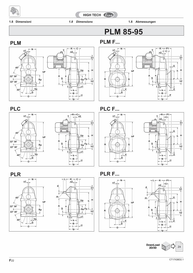
1.8 Dimensions1.8 Dimensioni 1.8 Abmessungen
2D 3DDownLoad
2D/3D Z4
PLM 25 - 45
PLM
PLM F...
NK
B
I
Ip
b
Y C
n2
n1
45°
45°
HP
a
S
f C1
i1
Gp
Up
AFp
h2
h1
h H
Vp
VpD
O
7 FORI
8 FORI
Rp
NK
B
I P
Ip
b
Y P1
n2C
n1
h
a
S
fZ
U
A
h2G
h1
hH
V
D
O
F
FFq
CT17IGBD2.1 F19
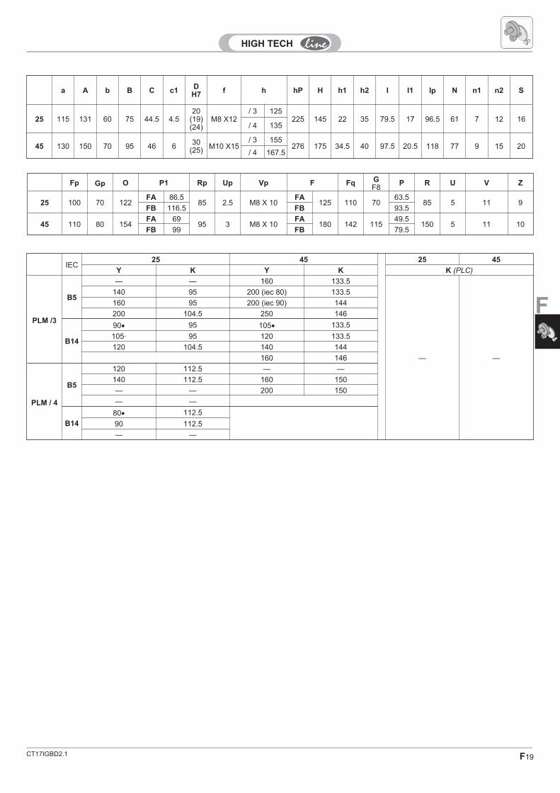
F
a A b B C c1D
H7f h hP H h1 h2 I I1 Ip N n1 n2 S
25 115 131 60 75 44.5 4.520
(19)(24)
M8 X12/ 3 125
225 145 22 35 79.5 17 96.5 61 7 12 16/ 4 135
45 130 150 70 95 46 6 30(25) M10 X15
/ 3 155276 175 34.5 40 97.5 20.5 118 77 9 15 20
/ 4 167.5
Fp Gp O P1 Rp Up Vp F Fq GF8
P R U V Z
25 100 70 122FA 86.5
85 2.5 M8 X 10FA
125 110 7063.5
85 5 11 9FB 116.5 FB 93.5
45 110 80 154FA 69
95 3 M8 X 10FA
180 142 11549.5
150 5 11 10FB 99 FB 79.5
IEC25 45 25 45
Y K Y K K (PLC)
PLM /3
B5
— — 160 133.5
— —
140 95 200 (iec 80) 133.5
160 95 200 (iec 90) 144
200 104.5 250 146
B14
90� 95 105� 133.5
105· 95 120 133.5
120 104.5 140 144
160 146
PLM / 4
B5
120 112.5 — —
140 112.5 160 150
— — 200 150
— —
B14
80� 112.5
90 112.5
— —

CT17IGBD2.1F20
2D 3DDownLoad
2D/3D Z4
PLM 65
PLM PLM F...
PLC PLC F...
PLR PLR F...
Dettaglio centraggio flangia pendolare.Quota "Gp".
45°
45°
22° 30'
22° 30'
N K
Rp
AS
a
Fp
n1n2
YC
hP
O
Ip
I
B
b
f c1Vp
D
h2
h1
h H
N K
Fq RA
S
a
G
n1
n2
YP1C
U
hP
O
F
Ip
I P
B
Zb
f
V
D
h2
h1
h H
45°
45°
22° 30'
22° 30'
N K
Rp
AS
a
Fp
n1n2Y
C
hP
OIp
I
B
b
f c1Vp
D
h2
h1
h H
N K
Fq R
AS
a
G
n1
n2Y
P1
U
C
hP
O
F
Ip
I
B
Zb
f
V
D
h2
h1
h H
P
45°
45°
22° 30'
22° 30'
N ML
Rp
AS
a
Fp
n1n2
C
hPm
d
O
Ip
I
B
b
f c1Vp
D
h2
h1
h H
N ML
Fq R
AS
a
G
n1
n2C
P1
U
m
d
hP
O
F
Ip
I
B
Zb
f
V
D
h2
h1
h H
8072
2 0.5
1.8 Dimensions1.8 Dimensioni 1.8 Abmessungen

CT17IGBD2.1 F21
F
PL.. a A b B C c1d
h6D
H7f h hP H h1 h2 I i1 Ip L N m M n1 n2 S
65 165 187 75 95 33.5 7.5 16 35(30)
M8X16
196 355 225 41 50 93 22 115 40 98 M6 133.5 10 14 22
PL.. S Fp Gp O P1 Rp Up Vp F Fq GF8
P R U V Z
65 22 120 7280 196 51.5 100 2 M8 X 20 F1 250 200 180
g6 43.5 215 4 14 11
IEC65 65
Y K K (PLC)
PLM /3
B5
140 104.5
65
160 104.5
200 124.5
250 134.5
B14
120 124.5
140 124.5
160 134.5
CT17IGBD2.1F22
2D 3DDownLoad
2D/3D Z4
PLM PLM F...
PLR PLR F...
2D 3DDownLoad
2D/3D Z4
PLM 85-95
PLC PLC F...
N K
Rp
AS
a
FpGp
n1n2
YC
hP
O
Ip
I
B
b
f c1
i1
Vp
D
h2
h1
hUp H
22° 30'
22° 30'
45°
45°
CN K
GR
hP
AS
a
n1n2
YP1
OIp
I
B
b
f
Z
P
V
D
h2
h1
h
U
H
F
YCN K
Rp
A
Sa
FpGp
n1 n2
hP
O
Ip
IB
b
f c1
i1
Vp
D
h2
h1
hUp H
22° 30'
22° 30'
45°
45°
YN K
GR
hP
AS
a
n1
n2
P1
C
OIp
IB
b
f
Z
i1
V
D
h2
h1
h
U
H
F
N KL
Rp
AS
aFpGp
n1 n2C
hP
O
Ip
I
B
b
f c1
i1
Vp
D
h2
h1
hUp H
22° 30'
22° 30'
45°
45°
d
m
N KL
GR
hP
AS
a
n1n2
P1
C
O
Ip
I
B
b
f
Z
i1
V
D
h2
h1
h
U
H
F
d
m
1.8 Dimensions1.8 Dimensioni 1.8 Abmessungen

CT17IGBD2.1 F23
F
a A b B C c1d
h6D
H7f h hP H h1 h2 I i1 Ip L N m M n1 n2 S
85 190 220 95 120 42 7.5 1945
(50)(40)
M12 237 422 260 57 60 115 25 140 40 111.5 M6 155 12 14 30
95 240 275 110 140 52 8.5 2455
(60)(50)
M14 298 528 325 73 70 136.5 26.5 163 50 136.5 M8 170.5 16 14 35
Fp Gp O P1 Rp Up Vp F GF8
P R U V Z
85 150 110 223 89 125 4.5 M8 X 12 F1 250 180 80.5 215 5 13 14
95 200 140 273 - 165 6 M12 F1 - - - - - - -
IEC85 95 85 95
Y K Y K K (PLC)
PLM /3
B5
160 121 200 151.5
74 76
200 136 250 161.5
250 146 300 182.5
300 170 350 212.5
B14
120 136
140 136
160 146
200 170

CT17IGBD2.1F24
NB
Output shaft end Ende der Abtriebswelle
ALBERI LENTI ABTRIEBSWELLENOUTPUT SHAFT
Estremità d'albero uscita
Ø AlberoØ Shaft
Ø Welle
Foro fil. testaTapped hole
Gewindebohrung Kopfi
CavaKeyway
Nut
Estremità d'alberoShaft end
Wellenende
LinguettaKey
Federkeil
T C C1 d f b t1 t2 R a bxhxl
25 20 g6 44.5 60.5 M 6 15 6 3.5 22.8 40 8 6x6x25
45 30 g6 46 84 M 10 25 8 4 33.3 60 5 8x7x50
65 35 g6 33.5 96.5 M 10 25 10 5 38.3 70 5 10x8x60
85 45 g6 42 113 M 10 25 14 5.5 48.8 90 5 14x9x80
95 55 g6 52 128 M 12 32 16 6 59.3 110 5 16x10x100

CT17IGBD2.1 F25
F
Albero lento cavo
ALBERI LENTI ABTRIEBSWELLENOUTPUT SHAFT
Output shaft with keyway Abtriebswelle mit passfedernut
-
Perno macchina / Customer shaft / Maschinachse
25 45 65 85 95C 44.5 46 33.5 42 52
C1 60.5 84 96.5 113 128
DH7
20(24)(19)
30(25)
35(30)
45(50)(40)
55(60)(50)
m1 25.5 40 35 42.5 55
ms - 20 - 15 17.5
Ls - 90 - 125 145
d1h6
m3 m3s Lm m HL
min
P R Ra Rb Sr Fe
2520
(24)(19)
30 3015
(25)(15)
M 6(M 8)(M 6)
103 4019.8
(23.8)(18.8)
30 - -
45 30(25) 45 8 25
(25)M 10(M 8) 98 50 29.8
(24.8) 40 8 M12
65 35(30) 40 40 25 M 10 128 60 34.8
(29.8) 45 - -
8545
(50)(40)
45 1525
(32)(25)
M 10(M 12)(M 10)
125 8044.8
(49.8)(39.8)
55(60)(50)
10 M14
9555
(60)(50)
60 20 32 M 12 142 11054.8
(59.8)(49.8)
65(70)(60)
15 M14

CT17IGBD2.1F26
Albero con calettatore
ALBERI LENTI ABTRIEBSWELLENOUTPUT SHAFT
Output shaft with shrink disc Abtriebswelle mit schrumpfscheibe
Perno macchina / Customer shaft / Maschinachse
C
d1h6
H m3 m4 P R Ra Rb
25 20 127 40 30 18.8 30
45 30 * * * 29.8 40
65 35 * * * 34.8 45
85 45 * * * 44.8 55
95 55 * * * 54.8 65
25 45 65 85 95
C 44.5 46 33.5 42 52
Cc 82.5 * * * *
C1 60.5 84 96.5 113 128
Ccs 66.5 * * * *
DH7
20 30 35 45 55
m1 35 * * * *
m2 25.5 * * * *
g 50 * * * *
Gg 3.5 * * * *
*Contattare il ns. servizio tecnico / Contact our technical dept / Wenden Sie sich an unseren technischen Service

CT17IGBD2.1 F27
F
D
ALBERI LENTI ABTRIEBSWELLENOUTPUT SHAFT
DB
Estremità albero lento scanalato senza
flangia brocciata
Abtriebswelle mit Keilende ohne
geräumtem Flansch
Splined output shaft without broached
flange
C C1de
(h10)F
Profilo scanalato / Splined profile / Keilprofil
Sc Z mn �dc(f7) Sp
25 44.5 60.5
*
-
*
45 46 84DIN 548235 x 31
65 33.5 96.5DIN 548240 x 36
85 42 113DIN 548258 x 53
95 52 128DIN 548270 x 64
*Contattare il ns. servizio tecnico / Contact our technical dept / Wenden Sie sich an unseren technischen Service

CT17IGBD2.1F28
ALBERI LENTI ABTRIEBSWELLENOUTPUT SHAFT
Perno macchina / Customer shaft / Maschinachse
25 45 65 85 95
C 44.5 46 33.5 42 52
C1 60.5 84 96.5 113 128
DH7
*m1
Lf
Sc - 28 x 25DIN 5482
35 x 31DIN 5482
45 x 41DIN 5482
55 x 50DIN 5482
CD
d1h6 m3 H P R Ra Rb Sc F Lf Lm m
25
* *
45
65
85
95
*Contattare il ns. servizio tecnico / Contact our technical dept / Wenden Sie sich an unseren technischen Service
Albero lento cavo scanalato Verzahnte HohlwelleSplined hollow shaft

CT17IGBD2.1 F29
F
FD FDB
Estremità scanalata albero lento flangia
brocciata
N
45°
45°F
ABCe
de
GIHGreaser
N. 2 holes E
N. holes D
C
Dimensioni generali / General dimensions / Allgemeine Abmessungen
de � A � B � C � C1 � Ce f8
N° Foriholes
Anzahl derBohrunge
n
� D E F G H INh9
25
*
44.5 60.5
*
45 46 84
65 33.5 96.5
85 42 113
95 52 128
Abtriebswelle mit Keilende und
geräumtem Flansch
Splined output shaft and broached
flange
ABTRIEBSWELLENOUTPUT SHAFTALBERI LENTI
*Contattare il ns. servizio tecnico / Contact our technical dept / Wenden Sie sich an unseren technischen Service

CT17IGBD2.1F30
1.8 Accessories1.8 Accessori 1.8 Zubehör
Tutti i riduttori sono forniti con albero lentocavo. A richiesta, possono essere forniti kitdi montaggio per alberi sporgenticomprensivi di linguette, rondelle e viti difissaggio. Le dimensioni delle linguettesono conformi alle norme UNI 6604-69.
All gearboxes are supplied with hollowoutput shaft. On request there are availablealso assembly kits including output shafts,keys, washers and assembly screws. Thedimensions of the keys are conform withUNI 6604-69.
Alle Getriebe werden mit Abtriebshohlwellegeliefert. Auf Anfrage sind auch Montagekitsinklusive Abtriebswellen, Paßfedern,Unterlegscheiben und Montageschraubenerhältlich. Die Abmessungen der Paßfedernsind konform mit der UNI 6604-69.
Alberi lenti AbtriebswellenOutput shafts
PL.. D1 D2 D3 L1 L2 H
85 12.5 40 40 16 4 260
95 12.5 40 40 16 4 325
L1
L1
L2
D3
D1
D2
H
L2 L2
B C C1Dg6 m2 L1 L2 Lm X
25* 10 44.5 60.5 20 M 8 25 40 20 8
45* 16 46 84 30 M 10 50 60 25 5
65* 15 33.5 96.5 35 M 10 60 70 25 5
85* 21 42 113 45 M 10 80 90 25 5
95* 26 52 128 55 M 12 100 110 32 5
*ATTENTIONThe output shaft is available only forstandard hollow shaft diameter.
Achtung:Die Einseitige Abtriebswelle wird fuerdie Montage bei Getrieben mitStandart Hohlwelle geliefert.
* ATTENZIONEL'albero lento sporgente è fornito peressere installato sulla versione del riduttorecon albero CAVO con diametroSTANDARD.

CT17IGBD2.1 F31
F
1.9 Keys 1.9 Paßfedern1.9 Linguette
Albero entrataInput shaftAntriebswelle
Albero uscitaOutput shaftAbtriebswelle
D bxh t2
19 6x6 2.80/ +0.1
20 8x7 2.8
24 8X7 3.3
0/ +0.2
25 8x7 3.3
28 8x7 3.3
30 8x7 3.3
32 10x8 3.3
35 10x8 3.3
40 12x8 3.3
42 12x8 3.3
45 14x9 3.8
48 14x9 3.8
50 14x9 3.8
55 16x10 4.3
60 18X11 4.4 0/ +0.3
d bxh t1
16 5x5 30/ +0.1
19 6x6 3.5
24 8x7 4 0/ +0.2
Tab. 4.17

CT17IGBD2.1F32