pm 21 - 2008 english - chapter 6
TRANSCRIPT
Siemens PM 21 · 2008
6/2 Built-on optoelectronicrotary encoders
6/2 Introduction
6/2 Incremental encoders6/3 TTL (RS 422)
incremental encoder6/3 sin/cos 1 Vpp
incremental encoder6/3 HTL incremental encoder6/3 TTL (RS 422) double-track
incremental encoder
6/6 Absolute encoders6/7 SSI absolute encoder6/7 Absolute encoder with
DRIVE-CLiQ6/7 EnDat absolute encoder6/7 PROFIBUS DP
absolute encoder
6/10 Mounting accessories
6/11 Hollow-shaft measuring system6/11 SIMAG H2 hollow-shaft
measuring system
Measuring systems
For products approved for Canada and U.S.A., see Appendix.
PM21_en_Kap06_ML1.fm Seite 1 Dienstag, 15. April 2008 4:19 16
© Siemens AG 2008
Measuring systemsBuilt-on optoelectronic rotary encoders
Introduction
6/2 Siemens PM 21 · 2008
6
■ Overview
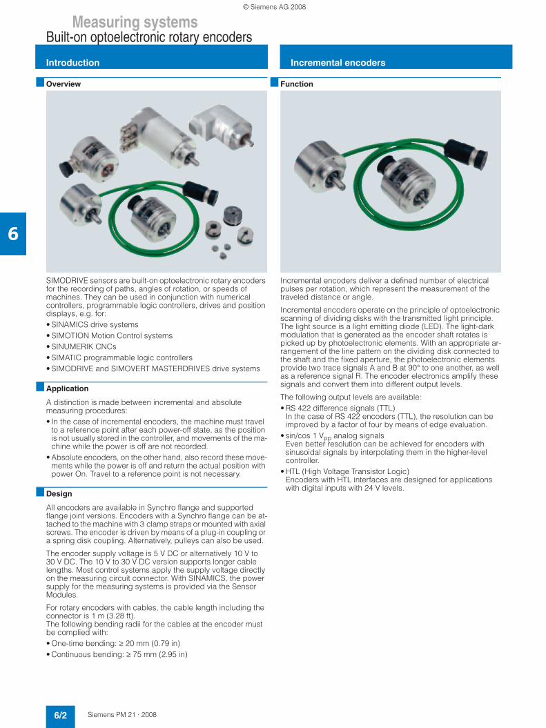
SIMODRIVE sensors are built-on optoelectronic rotary encoders for the recording of paths, angles of rotation, or speeds of machines. They can be used in conjunction with numerical controllers, programmable logic controllers, drives and position displays, e.g. for:• SINAMICS drive systems• SIMOTION Motion Control systems• SINUMERIK CNCs• SIMATIC programmable logic controllers• SIMODRIVE and SIMOVERT MASTERDRIVES drive systems
■ Application
A distinction is made between incremental and absolute measuring procedures:• In the case of incremental encoders, the machine must travel
to a reference point after each power-off state, as the position is not usually stored in the controller, and movements of the ma-chine while the power is off are not recorded.
• Absolute encoders, on the other hand, also record these move-ments while the power is off and return the actual position with power On. Travel to a reference point is not necessary.
■ Design
All encoders are available in Synchro flange and supported flange joint versions. Encoders with a Synchro flange can be at-tached to the machine with 3 clamp straps or mounted with axial screws. The encoder is driven by means of a plug-in coupling or a spring disk coupling. Alternatively, pulleys can also be used.
The encoder supply voltage is 5 V DC or alternatively 10 V to 30 V DC. The 10 V to 30 V DC version supports longer cable lengths. Most control systems apply the supply voltage directly on the measuring circuit connector. With SINAMICS, the power supply for the measuring systems is provided via the Sensor Modules.
For rotary encoders with cables, the cable length including the connector is 1 m (3.28 ft).The following bending radii for the cables at the encoder must be complied with:• One-time bending: ≥ 20 mm (0.79 in)• Continuous bending: ≥ 75 mm (2.95 in)
■ Function
Incremental encoders deliver a defined number of electrical pulses per rotation, which represent the measurement of the traveled distance or angle.
Incremental encoders operate on the principle of optoelectronic scanning of dividing disks with the transmitted light principle. The light source is a light emitting diode (LED). The light-dark modulation that is generated as the encoder shaft rotates is picked up by photoelectronic elements. With an appropriate ar-rangement of the line pattern on the dividing disk connected to the shaft and the fixed aperture, the photoelectronic elements provide two trace signals A and B at 90° to one another, as well as a reference signal R. The encoder electronics amplify these signals and convert them into different output levels.
The following output levels are available:• RS 422 difference signals (TTL)
In the case of RS 422 encoders (TTL), the resolution can be improved by a factor of four by means of edge evaluation.
• sin/cos 1 Vpp analog signals Even better resolution can be achieved for encoders with sinusoidal signals by interpolating them in the higher-level controller.
• HTL (High Voltage Transistor Logic)Encoders with HTL interfaces are designed for applications with digital inputs with 24 V levels.
Incremental encoders
PM21_en_Kap06_2-12.fm Seite 2 Dienstag, 15. April 2008 4:17 16
© Siemens AG 2008

Measuring systemsBuilt-on optoelectronic rotary encoders
Incremental encoders
6/3Siemens PM 21 · 2008
6
■ Technical specifications
S/R = signals/revolution1) With recommended cable and input circuitry of the downstream electronics, observe max. permissible cable length of module to be evaluated.
Product name TTL (RS 422) incremental encoder
sin/cos 1 Vppincremental encoder
HTLincremental encoder
TTL (RS 422) double-track incremental encoder
Operating voltage Vpon encoder
5 V DC ± 10 % or 10 … 30 V DC
5 V DC ± 10 % 10 ... 30 V DC 5 V DC ± 5 %
Limit frequency, typical – ≥ 180 kHz (-3 dB)≥ 450 kHz (-6 dB)
– –
Scanning frequency, max. 300 kHz – 300 kHz Track 1: 160 kHzTrack 2: 1 MHz
No-load current consumption, max.
150 mA 150 mA 150 mA 150 mA per track
Signal level TTL (RS 422) sinusoidal 1 Vpp VH ≥ 21 V at IH = 20 mA at 24 VVL ≤ 2.8 V at IL = 20 mA at 24 V
TTL (RS 422)
Outputs protected against short-circuit to 0 V
Yes Yes Yes Yes
Switching time (10 … 90 %)(1 m (3.28 ft) cable and recommended input circuit)
Rise/fall timet+/t- ≤ 50 ns
– Rise/fall timet+/t- ≤ 200 ns
Rise/fall timet+/t- ≤ 100 ns
Phase angle, signal A to B
Edge spacing, min. at90° 90° ± 10°el. 90° 90°
• 1 MHz – – – Track 2: ≥ 0.125 µs
• 300 kHz ≥ 0.45 µs – ≥ 0.45 µs –
• 160 kHz – – – Track 1: ≥ 0.8 µs
Cable length to down-stream electronics1), max.
100 m (328 ft) 150 m (492 ft) 300 m (984 ft) Up to 500 kHz: 100 m (328 ft)Up to 1 MHz: 50 m (164 ft)
LED failure monitoring High-resistance driver – High-resistance driver –
Resolution, max. 5000 S/R 2500 S/R 2500 S/R Track 1: 1024 S/RTrack 2: 9000 S/R
Accuracy
(in angular seconds)± 18° mech. x 3600/number of signals/revolution z
± 18° mech. x 3600/number of signals/revolution z
± 18° mech. x 3600/number of signals/revolution z
Track 1: ± 63Track 2: ± 12
Speed, max.
• Electrical (18 × 106 rpm)/number of signals/revolution
(27 × 106 rpm)/number of signals/revolution(at -6 dB)
(18 × 106 rpm)/number of signals/revolution
Track 1: 9000 rpmTrack 2: 6500 rpm
• Mechanical 12000 rpm 12000 rpm 12000 rpm 12000 rpm
Friction torque
(at 20 °C) (68 °F)≤ 0.01 Nm (0.08 lbf-in) ≤ 0.01 Nm (0.08 lbf-in) ≤ 0.01 Nm (0.08 lbf-in) ≤ 0.01 Nm (0.08 lbf-in)
Starting torque
(at 20 °C) (68 °F)≤ 0.01 Nm (0.08 lbf-in) ≤ 0.01 Nm (0.08 lbf-in) ≤ 0.01 Nm (0.08 lbf-in) ≤ 0.01 Nm (0.08 lbf-in)
Shaft loading capacity
• n > 6000 rpm
- Axial 10 N (2.25 lbf) 10 N (2.25 lbf) 10 N (2.25 lbf) –
- Radial at shaft extension 20 N (4.50 lbf) 20 N (4.50 lbf) 20 N (4.50 lbf) –
• n ≤ 6000 rpm
- Axial 40 N (8.99 lbf) 40 N (8.99 lbf) 40 N (8.99 lbf) 10 N (2.25 lbf)
- Radial at shaft extension 60 N (13.5 lbf) 60 N (13.5 lbf) 60 N (13.5 lbf) 20 N (4.50 lbf)
Angular acceleration, max. 105 rad/s2 105 rad/s2 105 rad/s2 105 rad/s2
Moment of inertia of rotor 1.45 × 10⁻⁶ kgm2
(12.8 x 10⁻⁶ lbf-in-s2)1.45 × 10⁻⁶ kgm2
(12.8 x 10⁻⁶ lbf-in-s2)1.45 × 10⁻⁶ kgm2
(12.8 x 10⁻⁶ lbf-in-s2)20 × 10-6 kgm2
(177 x 10-6 lbf-in-s2)
Vibration (55 … 2000 Hz) to EN 60068-2-6
≤ 300 m/s2 (984 ft/s2) ≤ 300 m/s2 (984 ft/s2) ≤ 300 m/s2 (984 ft/s2) ≤ 100 m/s2 (328 ft/s2)
Shock to EN 60068-2-27
• 2 ms ≤ 2000 m/s2 (6562 ft/s2) ≤ 2000 m/s2 (6562 ft/s2) ≤ 2000 m/s2 (6562 ft/s2) –
• 6 ms ≤ 1000 m/s2 (3281 ft/s2) ≤ 1000 m/s2 (3281 ft/s2) ≤ 1000 m/s2 (3281 ft/s2) ≤ 1000 m/s2 (3281 ft/s2)
PM21_en_Kap06_2-12.fm Seite 3 Dienstag, 15. April 2008 4:17 16
© Siemens AG 2008
Measuring systemsBuilt-on optoelectronic rotary encoders
Incremental encoders
6/4 Siemens PM 21 · 2008
6
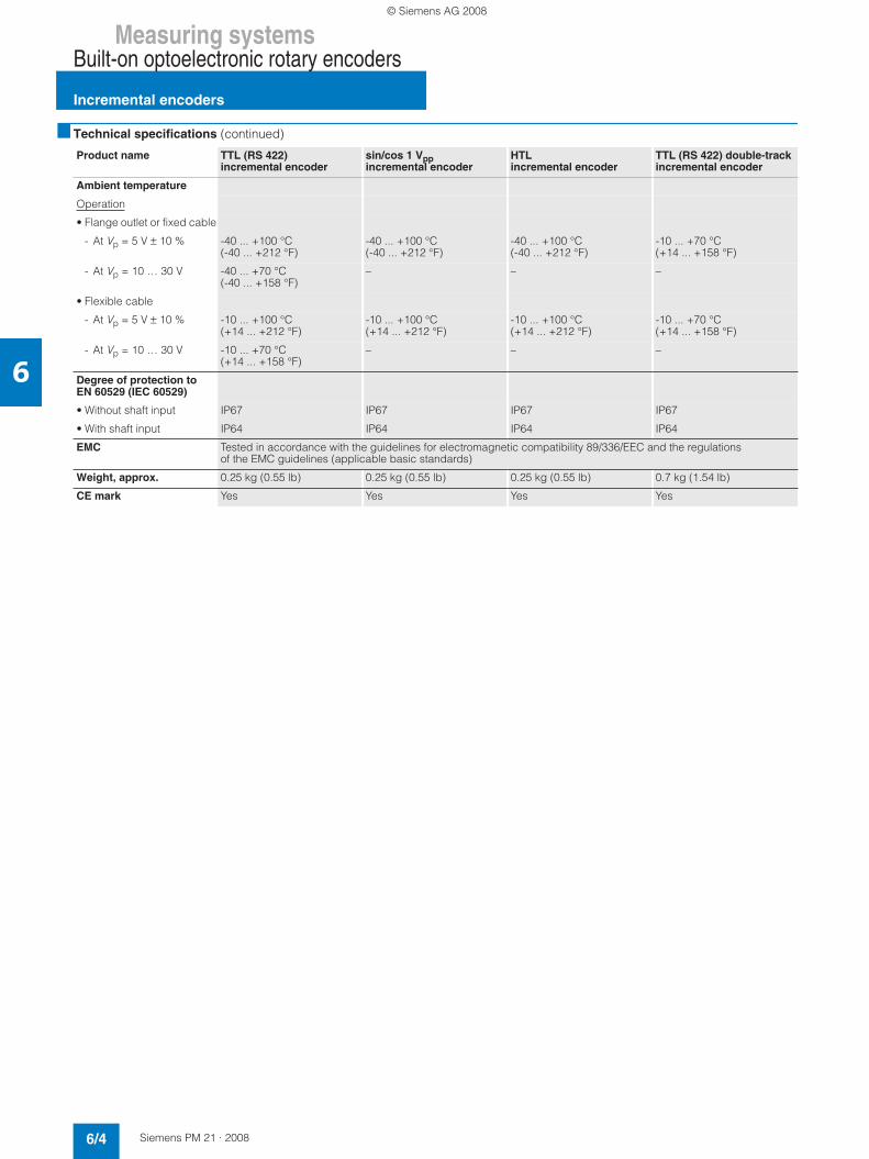
■ Technical specifications (continued)
Product name TTL (RS 422) incremental encoder
sin/cos 1 Vppincremental encoder
HTLincremental encoder
TTL (RS 422) double-track incremental encoder
Ambient temperature
Operation
• Flange outlet or fixed cable
- At Vp = 5 V ± 10 % -40 ... +100 °C (-40 ... +212 °F)
-40 ... +100 °C (-40 ... +212 °F)
-40 ... +100 °C (-40 ... +212 °F)
-10 ... +70 °C (+14 ... +158 °F)
- At Vp = 10 … 30 V -40 ... +70 °C (-40 ... +158 °F)
– – –
• Flexible cable
- At Vp = 5 V ± 10 % -10 ... +100 °C (+14 ... +212 °F)
-10 ... +100 °C (+14 ... +212 °F)
-10 ... +100 °C (+14 ... +212 °F)
-10 ... +70 °C (+14 ... +158 °F)
- At Vp = 10 … 30 V -10 ... +70 °C (+14 ... +158 °F)
– – –
Degree of protection to EN 60529 (IEC 60529)
• Without shaft input IP67 IP67 IP67 IP67
• With shaft input IP64 IP64 IP64 IP64
EMC Tested in accordance with the guidelines for electromagnetic compatibility 89/336/EEC and the regulations of the EMC guidelines (applicable basic standards)
Weight, approx. 0.25 kg (0.55 lb) 0.25 kg (0.55 lb) 0.25 kg (0.55 lb) 0.7 kg (1.54 lb)
CE mark Yes Yes Yes Yes
PM21_en_Kap06_2-12.fm Seite 4 Dienstag, 15. April 2008 4:17 16
© Siemens AG 2008
Measuring systemsBuilt-on optoelectronic rotary encoders
Incremental encoders
6/5Siemens PM 21 · 2008
6
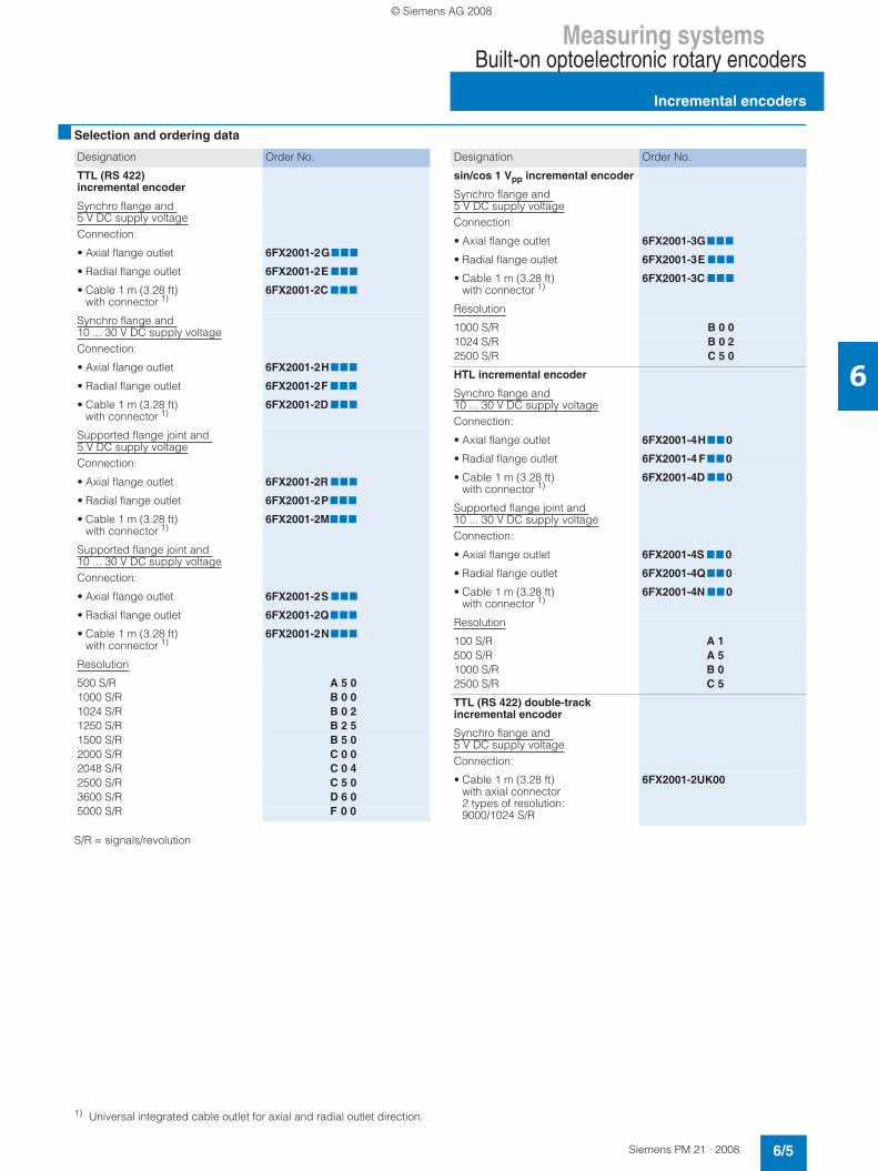
■ Selection and ordering data
S/R = signals/revolution
1) Universal integrated cable outlet for axial and radial outlet direction.
Designation Order No.
TTL (RS 422) incremental encoder
Synchro flange and 5 V DC supply voltageConnection:
• Axial flange outlet 6FX2001-2G777
• Radial flange outlet 6FX2001-2E 777
• Cable 1 m (3.28 ft) with connector 1)
6FX2001-2C 777
Synchro flange and 10 ... 30 V DC supply voltageConnection:
• Axial flange outlet 6FX2001-2H777
• Radial flange outlet 6FX2001-2F 777
• Cable 1 m (3.28 ft) with connector 1)
6FX2001-2D 777
Supported flange joint and 5 V DC supply voltageConnection:
• Axial flange outlet 6FX2001-2R 777
• Radial flange outlet 6FX2001-2P777
• Cable 1 m (3.28 ft) with connector 1)
6FX2001-2M777
Supported flange joint and 10 ... 30 V DC supply voltageConnection:
• Axial flange outlet 6FX2001-2S 777
• Radial flange outlet 6FX2001-2Q777
• Cable 1 m (3.28 ft) with connector 1)
6FX2001-2N777
Resolution
500 S/R A 5 01000 S/R B 0 01024 S/R B 0 21250 S/R B 2 51500 S/R B 5 02000 S/R C 0 02048 S/R C 0 42500 S/R C 5 03600 S/R D 6 05000 S/R F 0 0
Designation Order No.
sin/cos 1 Vpp incremental encoder
Synchro flange and 5 V DC supply voltageConnection:
• Axial flange outlet 6FX2001-3G777
• Radial flange outlet 6FX2001-3E 777
• Cable 1 m (3.28 ft) with connector 1)
6FX2001-3C 777
Resolution
1000 S/R B 0 01024 S/R B 0 22500 S/R C 5 0
HTL incremental encoder
Synchro flange and 10 ... 30 V DC supply voltageConnection:
• Axial flange outlet 6FX2001-4H770
• Radial flange outlet 6FX2001-4 F770
• Cable 1 m (3.28 ft) with connector 1)
6FX2001-4D 770
Supported flange joint and 10 ... 30 V DC supply voltageConnection:
• Axial flange outlet 6FX2001-4S 77 0
• Radial flange outlet 6FX2001-4Q77 0
• Cable 1 m (3.28 ft) with connector 1)
6FX2001-4N 770
Resolution
100 S/R A 1500 S/R A 51000 S/R B 02500 S/R C 5
TTL (RS 422) double-track incremental encoder
Synchro flange and 5 V DC supply voltageConnection:
• Cable 1 m (3.28 ft) with axial connector2 types of resolution: 9000/1024 S/R
6FX2001-2UK00
PM21_en_Kap06_2-12.fm Seite 5 Dienstag, 15. April 2008 4:17 16
© Siemens AG 2008
Measuring systemsBuilt-on optoelectronic rotary encoders
Absolute encoders
6/6 Siemens PM 21 · 2008
6
■ Function
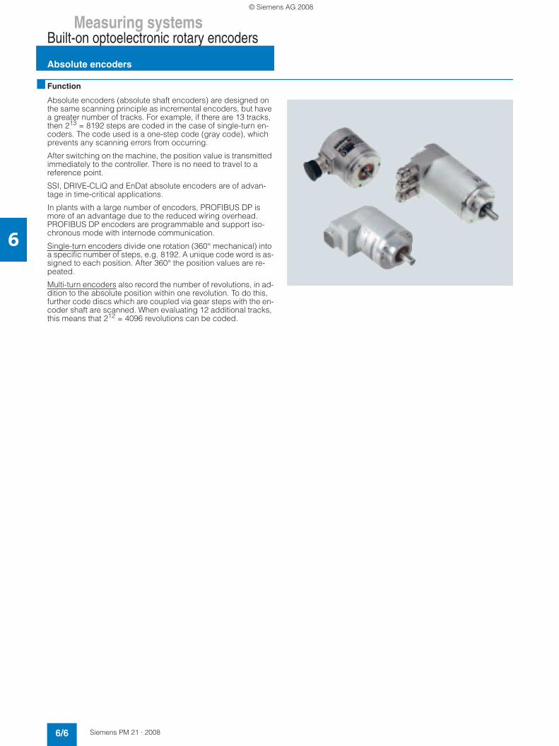
Absolute encoders (absolute shaft encoders) are designed on the same scanning principle as incremental encoders, but have a greater number of tracks. For example, if there are 13 tracks, then 213 = 8192 steps are coded in the case of single-turn en-coders. The code used is a one-step code (gray code), which prevents any scanning errors from occurring.
After switching on the machine, the position value is transmitted immediately to the controller. There is no need to travel to a reference point.
SSI, DRIVE-CLiQ and EnDat absolute encoders are of advan-tage in time-critical applications.
In plants with a large number of encoders, PROFIBUS DP is more of an advantage due to the reduced wiring overhead. PROFIBUS DP encoders are programmable and support iso-chronous mode with internode communication.
Single-turn encoders divide one rotation (360° mechanical) into a specific number of steps, e.g. 8192. A unique code word is as-signed to each position. After 360° the position values are re-peated.
Multi-turn encoders also record the number of revolutions, in ad-dition to the absolute position within one revolution. To do this, further code discs which are coupled via gear steps with the en-coder shaft are scanned. When evaluating 12 additional tracks, this means that 212 = 4096 revolutions can be coded.
PM21_en_Kap06_2-12.fm Seite 6 Dienstag, 15. April 2008 4:17 16
© Siemens AG 2008

Measuring systemsBuilt-on optoelectronic rotary encoders
Absolute encoders
6/7Siemens PM 21 · 2008
6
■ Technical specifications
1) Observe the maximum permissible cable length of the connected module.
Product name SSI absolute encoder Absolute encoder with DRIVE-CLiQ
EnDat absolute encoder PROFIBUS DP absolute encoder (EN 50170)
Operating voltage Vp on encoder
10 ... 30 V DC 24 V DC -15 % +20 % 5 V DC ± 5 % 10 ... 30 V DC
Power consumption, approx.
• Single-turn 160 mA 245 mA 160 mA 300 ... 100 mA (2.5 W)
• Multi-turn 200 mA 325 mA 200 mA 300 ... 100 mA (2.5 W)
Interface SSI DRIVE-CLiQ EnDat PROFIBUS
Clock input Differential cable receiver according to EIA standard RS 485
– Differential cable receiver according to EIA standard RS 485
Differential cable receiver according to EIA standard RS 485
Data output Differential cable driver according to EIA standard RS 485
DRIVE-CLiQ Differential cable driver according to EIA standard RS 485
Differential cable driver according to EIA standard RS 485
Short-circuit strength Yes Yes Yes Yes
Data transfer rate 100 kHz ... 1 MHz 100 Mbit 100 kHz ... 2 MHz 12 Mbit/s
LED for diagnostics – – – Yes (green/red)
Speed, max.
• Electrical – 14000 rpm – –
- At ± 1 bit accuracy 5000 rpm – 5000 rpm 5800 rpm
- At ± 100 bit accuracy 10000 rpm – 10000 rpm –
• Mechanical
- Single-turn 12000 rpm 12000 rpm 12000 rpm 12000 rpm
- Multi-turn 10000 rpm 10000 rpm 10000 rpm 6000 rpm
Cable length to down-stream electronics 1), max.
Up to 1-MHz-cycle: 50 m (164 ft)
100 m (328 ft) Up to 1-MHz-cycle: 50 m (164 ft)
Up to 12 Mbit/s: 100 m (328 ft)
Up to 300-kHz-cycle: 100 m (328 ft)
Up to 300-kHz-cycle: 150 m (492 ft)
Up to 1.5 Mbit/s: 200 m (656 ft)
Up to 100-kHz-cycle: 400 m (1312 ft)
Up to 93.75 kbit/s: 1200 m (3937 ft)
Number of nodes – – – 99
Connection Flange outlet, axial/radial DRIVE-CLiQ connector, radial
Flange outlet, axial/radial Terminal block with address selector switch and bus terminating resistor in removable cover with 3 radial cable glands
Cable diameter – – – 6.5 ... 9 mm (0.26 ... 0.35 in)Removal of cover possible without interrupting bus
Resolution
• Single-turn 13 bit (8192 steps) 22 bit 13 bit (8192 steps) 13 bit (8192 steps)
• Multi-turn 25 bit (8192 × 4096 steps)
34 bit (22 bit Single-turn + 12 bit Multi-turn)
25 bit (8192 × 4096 steps)
27 bit (8192 × 16384 steps)
Message frame length
• Single-turn 13 bit, without parity – According to EnDat specification
–
• Multi-turn 25 bit, without parity – According to EnDat specification
–
Incremental track – 2048 S/R, 1 Vpp(encoder-internal only)
512 S/R, 1 Vpp –
Code type
• Sampling Gray Binary (encoder-internal only)
Gray Gray
• Transfer Gray, fir tree format – Binary Binary
PM21_en_Kap06_2-12.fm Seite 7 Dienstag, 15. April 2008 4:17 16
© Siemens AG 2008

Measuring systemsBuilt-on optoelectronic rotary encoders
Absolute encoders
6/8 Siemens PM 21 · 2008
6
■ Technical specifications (continued)
Product name SSI absolute encoder Absolute encoder with DRIVE-CLiQ
EnDat absolute encoder PROFIBUS DP absolute encoder (EN 50170)
Parameterization capability
• Resolution per revolution – – – Arbitrary 1 ... 8192
• Total resolution – – – Arbitrary 1 ... 16384
• Preset Set to zero – – Arbitrary
• Counting direction Yes Yes – Yes
• Speed signal – – – Yes
• Limit switches – – – Yes, 2
• Isochronous mode and internode communication acc. to DP V2
– – – Yes
Online parameterization – – – Yes
Network load, approx. – – – 20 µs per encoder at 12 Mbit/s
Cycle time – – – 667 µs
Accuracy ± 60 angular seconds ± 36 angular seconds ± 60 angular seconds(incr. track)
± ½ LSB
EMC Tested in accordance with EN 50081 and EN 50082
Tested in accordance with EN 50081 and EN 50082
Tested in accordance with EN 50081 and EN 50082
Tested in accordance with EN 50081 and EN 50082
Friction torque(at 20 °C) (68 °F)
≤ 0.01 Nm (0.08 lbf-in) ≤ 0.01 Nm (0.08 lbf-in) ≤ 0.01 Nm (0.08 lbf-in) ≤ 0.01 Nm (0.08 lbf-in)
Starting torque(at 20 °C) (68 °F)
≤ 0.01 Nm (0.08 lbf-in) ≤ 0.01 Nm (0.08 lbf-in) ≤ 0.01 Nm (0.08 lbf-in) ≤ 0.01 Nm (0.08 lbf-in)
Shaft loading capacity
• n > 6000 rpm
- Axial 10 N (2.25 lbf) 10 N (2.25 lbf) 10 N (2.25 lbf) 10 N (2.25 lbf)
- Radial at shaft extension 20 N (4.50 lbf) 20 N (4.50 lbf) 20 N (4.50 lbf) 20 N (4.50 lbf)
• n ≤ 6000 rpm
- Axial 40 N (8.99 lbf) 40 N (8.99 lbf) 40 N (8.99 lbf) 40 N (8.99 lbf)
- Radial at shaft extension 60 N (13.5 lbf) 60 N (13.5 lbf) 60 N (13.5 lbf) 110 N (24.7 lbf)
Angular acceleration, max. 105 rad/s2 105 rad/s2 105 rad/s2 105 rad/s2
Moment of inertia of rotor
• Solid shaft 1.45 × 10⁻⁶ kgm2
(12.8 x 10⁻⁶ lbf-in-s2)1.90 × 10⁻⁶ kgm2
(16.8 x 10⁻⁶ lbf-in-s2)1.45 × 10⁻⁶ kgm2
(12.8 x 10⁻⁶ lbf-in-s2)1,90 × 10⁻⁶ kgm2
(16.8 x 10⁻⁶ lbf-in-s2)
• Hollow shaft – 2.80 × 10⁻⁶ kgm2
(24.8 x 10⁻⁶ lbf-in-s2)– 2.80 × 10⁻⁶ kgm2
(24.8 x 10⁻⁶ lbf-in-s2)
Vibration (55 … 2000 Hz) to EN 60068-2-6
≤ 300 m/s2 (984 ft/s2) ≤ 100 m/s2 (328 ft/s2) ≤ 300 m/s2 (984 ft/s2) ≤ 100 m/s2 (328 ft/s2)
Shock to EN 60068-2-27
• 2 ms ≤ 2000 m/s2 (6562 ft/s2) ≤ 2000 m/s2 (6562 ft/s2) ≤ 2000 m/s2 (6562 ft/s2) ≤ 2000 m/s2 (6562 ft/s2)
• 6 ms ≤ 1000 m/s2 (3281 ft/s2) ≤ 1000 m/s2 (3281 ft/s2) ≤ 1000 m/s2 (3281 ft/s2) ≤ 1000 m/s2 (3281 ft/s2)
Ambient temperature
• Operation -40 ... +85 °C (-40 ... +185 °F)
-20 ... +100 °C (-4 ... +212 °F)
-40 ... +100 °C (-40 ... +212 °F)
-40 ... +85 °C (-40 ... +185 °F)
Degree of protection to EN 60529 (IEC 60529)
• Without shaft input IP67 IP67 IP67 IP67
• With shaft input IP64 IP64 IP64 IP64
Weight, approx.
• Single-turn 0.35 kg (0.77 lb) 0.40 kg (0.88 lb) 0.35 kg (0.77 lb) 0.5 kg (1.10 lb)
• Multi-turn 0.35 kg (0.77 lb) 0.44 kg (0.97 lb) 0.35 kg (0.77 lb) 0.7 kg (1.54 lb)
CE mark Yes Yes Yes Yes
PROFIBUS certificate – – – Yes
Supported profiles – – – Class 1, Class 2
PM21_en_Kap06_2-12.fm Seite 8 Dienstag, 15. April 2008 4:17 16
© Siemens AG 2008
Measuring systemsBuilt-on optoelectronic rotary encoders
Absolute encoders
6/9Siemens PM 21 · 2008
6
■ Selection and ordering data
■ More information
Designation Order No.
SSI absolute encoder
Synchro flange and10 ... 30 V DC supply voltageConnection:
• Axial flange outlet 6FX2001-5HS77
• Radial flange outlet 6FX2001-5F S 77
Supported flange joint and10 ... 30 V DC supply voltageConnection:
• Axial flange outlet 6FX2001-5 SS77
• Radial flange outlet 6FX2001-5QS77
Resolution
• Single-turn8192 steps/revolution (13 bit)
1 2
• Multi-turn8192 steps/revolution, 4096 revolutions (25 bit)
2 4
Absolute encoder with DRIVE-CLiQ
24 V DC supply voltageRadial connection
• Synchro flangeSolid shaft 6 mm (0.24 in)
6FX2001-5FD 77-0AA0
• Supported flange jointSolid shaft 10 mm (0.39 in)
6FX2001-5QD77-0AA0
• Torque bracketHollow shaft 10 mm (0.39 in)
6FX2001-5VD 77-0AA0
• Torque bracketHollow shaft 12 mm (0.47 in)
6FX2001-5WD77-0AA0
Resolution
• Single-turn 22 bit 1 3
• Multi-turn 34 bit 2 5
EnDat absolute encoder
Synchro flange and 5 V DC supply voltageConnection:
• Axial flange outlet 6FX2001-5HE77
• Radial flange outlet 6FX2001-5F E 77
Supported flange joint and 5 V DC supply voltageConnection:
• Axial flange outlet 6FX2001-5 SE77
• Radial flange outlet 6FX2001-5QE77
Resolution
• Single-turn8192 steps/revolution (13 bit)
1 3
• Multi-turn8192 steps/revolution, 4096 revolutions (25 bit)
2 5
Designation Order No.
PROFIBUS DP absolute encoder (EN 50170)
10 ... 30 V DC supply voltageRadial connection
• Synchro flangeSolid shaft
6FX2001-5F P 77
• Supported flange jointSolid shaft
6FX2001-5QP77
• Torque bracketHollow shaft 8 mm/10 mm/12 mm/15 mm (0.31 in/0.39 in/0.47 in/0.59 in)
6FX2001-5WP77
Resolution
• Single-turn8192 steps/revolution (13 bit)
1 2
• Multi-turn8192 steps/revolution, 16384 revolutions (27 bit)
2 4
User Manualfor start-up and parameterization of PROFIBUS encodersLanguage: English/German
6SN1197-0AB10-0YP4
Designation Order No.
Decentralizing with PROFIBUS DP
ISBN3-89578-074-X
PM21_en_Kap06_2-12.fm Seite 9 Dienstag, 15. April 2008 4:17 16
© Siemens AG 2008

Measuring systemsBuilt-on optoelectronic rotary encoders
Mounting accessories
6/10 Siemens PM 21 · 2008
6
■ Overview
Clamp straps/couplings
Clamp straps and couplings are available as mounting accesso-ries for the rotary encoders. The clamp straps are used to fix the encoders with a Synchro flange.
Mating connector
A mating connector is available for the encoder with flange outlet or with cable and encoder connector for cable diameters 5.5 mm (0.22 in) to 12 mm (0.47 in). Connectors with 12 contacts are suitable for all incremental encoders, as well as SSI absolute encoders. Connectors with 17 contacts are suitable for EnDat encoders.
Replacement connector
A replacement connector is available for encoders with cable.
■ Technical specifications
■ Selection and ordering data
Product name Spring disk coupling
Plug-incoupling
Transmission torque, max.
0.8 Nm (2.88 ozf) 0.7 Nm (2.52 ozf)
Shaft diameter 6 mm (0.24 in) both ends or d1 = 6 mm (0.24 in), d2 = 5 mm (0.20 in)
6 mm (0.24 in) both ends or 10 mm (0.39 in) both ends
Center offset of shafts, max.
0.4 mm (0.02 in) 0.5 mm (0.02 in)
Axial offset ± 0.4 mm (0.02 in) ± 0.5 mm (0.02 in)
Angular displacement of shafts, max.
3° 1°
Torsional rigidity 150 Nm/rad (539.51 ozf/rad)
31 Nm/rad (111.5 ozf/rad)
Lateral spring stiffness 6 N/mm (1.35 lbf) 10 N/mm (2.25 lbf)
Moment of inertia 19 gcm2
(168 x 10-7 lbf-in-s2)
20 gcm2
(177 x 10-7 lbf-in-s2)
Speed, max. 12000 rpm 12000 rpm
Ambient temperature
• Operation -40 ... +150 °C (-40 ... +302 °F)
-40 ... +80 °C (-40 ... +176 °F)
Weight, approx. 16 g (0.56 oz) 20 g (0.71 oz)
Designation Order No.
Clamp strap
For double-track encoders and encoders with Synchro flange (3 units are required)
6FX2001-7KP01
Spring disk coupling
Shaft diameter:
• 6 mm/6 mm (0.24 in/0.24 in) 6FX2001-7KF10
• 6 mm/5 mm (0.24 in/0.20 in) 6FX2001-7KF06
Plug-in coupling
Shaft diameter:
• 6 mm/6 mm (0.24 in/0.24 in) 6FX2001-7KS06
• 10 mm/10 mm (0.39 in/0.39 in) 6FX2001-7KS10
Mating connector for flange outlet or encoder connector with cap nut(1 unit) Crimp version, socket contacts for cable diameters 5.5 … 12 mm (0.22 … 0.47 in)
• 12-pin, insulator with 12 socket contacts (1 unit) for TTL, sin/cos 1 Vpp,HTL incremental encodersor for SSI absolute encoders
6FX2003-0SU12
• 17-pin, insulator with 17 socket contacts (1 unit) for EnDat absolute encoders
6FX2003-0SU17
Replacement connectors with external thread for encoders(1 unit)• 12-pin, insulator with
12 contact pins (1 unit) for RS 422, sin/cos 1 Vpp,HTL incremental encodersfor SSI absolute encoders
6FX2003-0SA12
PM21_en_Kap06_2-12.fm Seite 10 Dienstag, 15. April 2008 4:17 16
© Siemens AG 2008

Measuring systemsHollow-shaft measuring system
SIMAG H2 hollow-shaft measuring system
6/11Siemens PM 21 · 2008
6
■ Application
SIMAG H2 is an incremental system for measuring angles of rotation and rotational speeds. The application range comprises hollow-shaft applications with direct drives, as well as autono-mous spindle encoder applications.
The electrical signals and the flange outlet are compatible with existing motor measuring systems. SIMAG H2 can be operated with all commonly available controls as a motor measuring sys-tem or a direct measuring system.
■ Design
The SIMAG H2 measuring system consists of three components:• Measuring wheel• Scanning head with connecting lead• Connection kit
The magnetic division on the measuring wheel is used as the unit of measurement. Different internal diameters are available for each external diameter. The internal diameter can be re-worked. The measuring wheel is attached with the shaft nut; alternatives are screw fitting to a shaft shoulder (not possible with all measuring wheel variants) or shrink fitting.
The non-contact sensor head scans the incremental and refer-ence tracks on the measuring wheel and amplifies the signals.
It is connected via a cable attached to the scanning head. The end of the cable is pre-assembled with contacts and an insula-tion insert. For assembly, the insulation insert can be fixed into a straight or angular flange outlet. For confined spaces, the en-coder can also be supplied with open wire ends.
■ Technical specifications
S/R = signals/revolution
Product name SIMAG H2 hollow-shaft measuring system
Output signals 2 voltage signals 1 Vppin quadrate; 1 reference signal per encoder rotation
Operating voltage 5 V DC ± 5 %Power consumption, typical 30 mAResolution
(with external diameter Da) 192 S/R (Da = 60.72 mm/2.39 in)256 S/R (Da = 81.14 mm/3.19 in)400 S/R (Da = 126.92 mm/5.00 in)480 S/R (Da = 152.39 mm/6.00 in)800 S/R (Da = 254.25 mm/10.0 in)
Indexing accuracy of measuring wheel• Resolution = 192 S/R ± 96 angular seconds• Resolution = 256 S/R ± 72 angular seconds• Resolution = 400 S/R ± 46 angular seconds• Resolution = 480 S/R ± 38 angular seconds• Resolution = 800 S/R ± 23 angular secondsLimit speed• Resolution = 192 S/R ≤ 33000 rpm• Resolution = 256 S/R ≤ 25000 rpm• Resolution = 400 S/R ≤ 16000 rpm• Resolution = 480 S/R ≤ 13000 rpm• Resolution = 800 S/R ≤ 8000 rpmDistance between measuring wheel and scanning head
200 µm
Ambient temperature• Operation -20 ... +120 °C (-4 ... +248 °F)Shock resistance (11 ms) 1000 m/s2 (3281 ft/s2)Vibration (50 ... 2000 Hz) 200 m/s2 (656 ft/s2)Degree of protection to EN 60529 (IEC 60529)• when installed IP67Bending radius of connecting cable• One-time bending ≥ 25 mm (0.98 in)• Repeated bending ≥ 60 mm (2.36 in)Length of cable to converter, max. 50 m (164 ft)Dimensions, approx.Scanning head (mounted)• Width 36 mm (1.42 in)• Height 18 mm (0.71 in)• Depth 15 mm (0.59 in)
PM21_en_Kap06_2-12.fm Seite 11 Dienstag, 15. April 2008 4:17 16
© Siemens AG 2008

Measuring systemsHollow-shaft measuring system
SIMAG H2 hollow-shaft measuring system
6/12 Siemens PM 21 · 2008
6
■ Technical specifications (continued)
Measuring wheels
1) The measuring wheels can be re-worked (by increasing the inner diameter or by drilling holes/tapping threads). See Configuring/ Installation Guide.
■ Selection and ordering data
Measuring wheel external diameter Da = 60.72 mm (2.39 in)
Internal diameter 1) 40H6 mm (1.57H6 in)
Thickness 15 mm (0.59 in)
Resolution 192 S/R
Moment of inertia, approx.
1.0 × 10⁻⁴ kgm2 (8.85 x 10⁻⁴ lbf-in-s2)
Weight, approx. 0.20 kg (0.44 lb)
Measuring wheel external diameter Da = 81.14 mm (3.19 in)
Internal diameter 1) 45H6 mm(1.76H6 in)
55H6 mm(2.17H6 in)
60H6 mm(2.36H6 in)
65H6 mm(2.56H6 in)
Thickness 15 mm (0.59 in)
15 mm (0.59 in)
15 mm (0.59 in)
15 mm (0.59 in)
Resolution 256 S/R 256 S/R 256 S/R 256 S/R
Moment of inertia, approx.
3.8 x10⁻⁴ kgm2
(33.6 x 10⁻⁴
lbf-in-s2)
3.2 x10⁻⁴ kgm2
(28.3 x 10⁻⁴
lbf-in-s2)
2.8 x10⁻⁴ kgm2
(24.8 x 10⁻⁴
lbf-in-s2)
2.2 x10⁻⁴ kgm2
(19.5 x 10⁻⁴
lbf-in-s2)
Weight, approx. 0.35 kg (0.77 lb)
0.30 kg (0.66 lb)
0.25 kg (0.55 lb)
0.20 kg (0.44 lb)
Measuring wheel external diameter Da = 126.92 mm (5.00 in)
Internal diameter 1) 65H6 mm(2.56H6 in)
85H6 mm(3.35H6 in)
100H6 mm(3.94H6 in)
Thickness 15 mm (0.59 in) 15 mm (0.59 in) 15 mm (0.59 in)
Resolution 400 S/R 400 S/R 400 S/R
Moment of inertia, approx.
25 × 10-4 kgm2
(221 x 10-4 lbf-in-s2)
21 × 10-4 kgm2
(186 x 10-4 lbf-in-s2)
16 × 10-4 kgm2
(142 x 10-4 lbf-in-s2)
Weight, approx. 1.0 kg (2.20 lb)
0.75 kg (1.65 lb)
0.5 kg (1.10 lb)
Measuring wheel external diameter Da = 152.39 mm (6.00 in)
Internal diameter 1) 80H6 mm(3.15H6 in)
110H6 mm(4.33H6 in)
Thickness 15 mm (0.59 in)
15 mm (0.59 in)
Resolution 480 S/R 480 S/R
Moment of inertia, approx.
54 × 10-4 kgm2
(478 x 10-4 lbf-in-s2)
42 × 10-4 kgm2
(372 x 10-4 lbf-in-s2)
Weight, approx. 1.5 kg (3.31 lb) 1.0 kg (2.20 lb)
Measuring wheel external diameter Da = 254.25 mm (10.0 in)
Internal diameter 1) 150H6 mm (5.91H6 in)
Thickness 15 mm (0.59 in)
Resolution 800 S/R
Moment of inertia, approx.
420 × 10-4 kgm2 (3717 x 10-4 lbf-in-s2)
Weight, approx. 3.9 kg (8.60 lb)
Designation Order No.
Scanning head, incremental1 mm (0.04 in) pole pitch, 1 Vpp
• With plug insert and 0.3 m (11.8 in) temperature cable (2-core)
- With 0.2 m (7.87 in) signal cable
6FX2001-6AA12-1CA0
- With 0.5 m (19.7 in) signal cable
6FX2001-6AA12-1FA0
- With 2.0 m (6.56 ft) signal cable
6FX2001-6AA12-3AA0
• With open wire ends
- With 1.0 m (3.28 ft) signal cable
6FX2001-6AA12-2AA5
- With 1.5 m (4.92 ft) signal cable
6FX2001-6AA12-2FA8
- With 3.5 m (11.5 ft) signal cable
6FX2001-6AA12-4FA0
Measuring wheel Da = 60.72 mm (2.39 in) 6FX2001-6RB12-3EA0
• Internal diameter 40H6 mm(1.57H6 in)
Measuring wheel Da = 81.14 mm (3.19 in)
• Internal diameter 45H6 mm(1.77H6 in)
6FX2001-6RB12-4EF0
• Internal diameter 55H6 mm(2.17H6 in)
6FX2001-6RB12-4FF8
• Internal diameter 60H6 mm(2.36H6 in)
6FX2001-6RB12-4GA0
• Internal diameter 65H6 mm(2.56H6 in)
6FX2001-6RB12-4GF0
Measuring wheel Da = 126.92 mm (5.00 in)
• Internal diameter 65H6 mm(2.56H6 in)
6FX2001-6RB12-5GF0
• Internal diameter 85H6 mm(3.35H6 in)
6FX2001-6RB12-5JF0
• Internal diameter 100H6 mm(3.94H6 in)
6FX2001-6RB12-5LA0
Measuring wheel Da = 152.39 mm (6.00 in)
• Internal diameter 80H6 mm(3.15H6 in)
6FX2001-6RB12-6JA0
• Internal diameter 110H6 mm(4.33H6 in)
6FX2001-6RB12-6MA0
Measuring wheel Da = 254.25 mm (10.0 in) 6FX2001-6RB12-7SA0
• Internal diameter 150H6 mm(5.91H6 in)
Connection kit for insulation insert
• Straight flange outlet 6FX2001-6FA12-0GA0
• Angular flange outlet 6FX2001-6FA12-0WA0
Extraction tool for insulation insert
6FX2001-6FK12-0AA0
Of flange outlet, straight or angled
PM21_en_Kap06_2-12.fm Seite 12 Dienstag, 15. April 2008 4:17 16
© Siemens AG 2008