pm synchronous motor dynamic modeling with genetic
TRANSCRIPT

MultiCraft
International Journal of Engineering, Science and Technology
Vol. 2, No. 2, 2010, pp. 93-106
INTERNATIONAL JOURNAL OF ENGINEERING, SCIENCE AND TECHNOLOGY
www.ijest-ng.com
2010 MultiCraft Limited. All rights reserved
Permanent magnet synchronous motor dynamic modeling with genetic algorithm performance improvement
Adel El Shahat1*, Hamed El Shewy2
1*Department of Electrical and Computer Engineering, Ohio State University, USA
2Department of Electrical Power and Machines Engineering, Zagazig University, EGYPT *Corresponding Authors: (e.mails: [email protected]; [email protected])
Abstract This paper proposes dynamic modeling simulation for ac Surface Permanent Magnet Synchronous Motor (SPMSM) with the aid of MATLAB – Simulink environment. The proposed model would be used in many applications such as automotive, mechatronics, green energy applications, and machine drives. The modeling procedures are described and simulation results are presented. The validity of this dynamic model here is verified. Then, two genetic algorithm trials are presented to improve SPMSM performance. Maximum torque per ampere genetic algorithm function with maximum efficiency constrained is illustrated. Also, genetic algorithm maximum efficiency function constrained by GA maximum power factor is proposed. Simulations are implemented using MATLAB with its genetic algorithm toolbox. Finally, the required voltage to drive the motor at the desired improved characteristics is deduced for each case. All various characteristics are well depicted in the form of comparisons with such ones from original characteristics at rated voltage. Keywords- Permanent Magnet, Synchronous Motor, Simulink, Genetic Algorithm, optimization and MATLAB
1. Introduction Permanent magnet (PM) motor drives have been a topic of interest for the last twenty years due to its suitability for many topics like in automotive, mechatronics, green energy applications, and machine drives. Pillay and Krishnan (1988, 1989) presented PM motor drives and classified them into two types such as permanent magnet synchronous motor drives (PMSM) and brushless dc motor (BDCM) drives. Morimoto et al. (1994), in their paper, aimed to improve efficiency in permanent magnet (PM) synchronous motor drives. The paper of Wijenayake and Schmidt (1997) described the development of a two-axis circuit model for permanent magnet synchronous motor (PMSM) by taking machine magnetic parameter variations and core loss into account. Jang-Mok and Seung-Ki (1997) proposed a novel flux-weakening scheme for an Interior Permanent Magnet Synchronous Motor (IPMSM). Bose (2002) presented different types of synchronous motors and compared them to induction motors. Mademlis and Margaris, (2002) presented an efficiency optimization method for vector-controlled interior permanent-magnet synchronous motor drive. Jian-Xin, et al. (2004) applied a modular control approach to a permanent magnet synchronous motor (PMSM) speed control. Onoda and Emadi (2004) had developed a modeling tool to study automotive systems using the power electronics simulator (PSIM) software. Genetic algorithm is based on natural evolution. As a result, much of the terminology is drawn from biology and evolution (Goldberg, 1989). Genetic algorithm is started by randomly generating a population of strings, representing the encoded parameters. The strings are then evaluated to obtain a quantitative measure of how well they perform as possible problem solution. Genetic operators are crossover and mutation. Crossover produces one pair of output strings for a given pair of input string. Mutation is a unary operator which takes a binary string as its input and outputs a binary string that is almost identical to the input string except at most at a single bit (Rudolph, 1994). Since Holland (1995) presented the GA as a computer algorithm, a wide range of applications of GA has appeared in various scientific areas, and GA has been proved powerful enough to solve the complicated problems, especially the optimal design problems. Some of the possible methods are to fix the number of generations and to use the best individual of all generations as the optimum result; to fix the time elapsed and to select the optimum similarly; or to let the entire population converge in to an average fitness with some error margin (Cvetkovski et al., 1998). El Shahat et al.

El Shahat and El Shewy / International Journal of Engineering, Science and Technology, Vol. 2, No. 2, 2010, pp. 93-106
94
(2010) used the genetic algorithm in an efficient manner in high speed PM synchronous motor flywheel design aspects. Finally, noticeable efforts are introduced in the topic of PM machines modeling and improving the machine performance using artificial intelligence like neural network, genetic algorithm, etc (El Shahat and El Shewy, 2009a,b,d,e, 2010; El Shahat et al., 2010; El Shewy et al., 2008). 2. Dynamic Modeling of PMSM Figure 1 presents equivalent circuit of PMSM in d-q axis to be used in both dynamic equations of PMSM, and static characteristics.
Figure1. PMSM Equivalent Circuit
The two axes PMSM stator windings can be considered to have equal turns per phase. The rotor flux can be assumed to be concentrated along the d axis while there is zero flux along the q axis. Further, it is assumed that the machine core losses are negligible. Also, rotor flux is assumed to be constant. Variations in rotor temperature alter the magnet flux, but its variation with time is considered to be negligible. A dynamic model of PMSM can be illustrated as follow (Krishnan, 2006):
vq = rs iq + ρ ( λq ) + ωr λd (1)
vd = rs id + ρ ( λd ) – ωr λq (2)
λq = Lq iq (3)
λd = Ld id + λaf (4)
where ωr : Electrical velocity of the rotor; λaf : The flux linkage due to the rotor magnets linking the stator; vd, vq : d, q voltages; λd, λq : d, q flux ρ (λaf) = 0, λaf = Lm ifr; ρ : Operator The electromagnetic torque is given by:
Te=23 )(
2 dqqd iiP
λλ − =23
))((2 dqqdqm iiLLiP
−+λ (5)
The electromechanical power
Pem = ωrm Te = 23ωr ( λd iq – λq id ) (6)
ωr = 2P
ωrm (7)
where P: Poles No; ωrm: Rotor Mechanical velocity The general mechanical equation for the motor is:
Te = Tl + Td + B ωrm + J ρ ωrm (8)
where B: Viscous friction’s coefficient; J: Inertia of the shaft and the load system; Td : Dry friction; Tl: Load torque 3. Dynamic Modeling & Simulation Results This dynamic simulation of PMSM is done with the aid of SIMULINK in MATLAB package.

El Shahat and El Shewy / International Journal of Engineering, Science and Technology, Vol. 2, No. 2, 2010, pp. 93-106
95
Figure2. PMSM Dynamic Model Block
Figure 2 presents PMSM block in which, voltage and load torque are considered as inputs, with the speed and current as outputs. In this model some assumptions included: 1) Saturation is neglected. 2) The induced EMF is sinusoidal. 3) Eddy currents and hysteresis losses are negligible. 4) There are no field current dynamics. 5) All motor parameters are assumed constant. 6) Leakage inductances are zero.
Ns1
current in q -axis
u(1)/Lq
current in d -axis
f(u)
Te Calculation
f(u)
Sine Wave 3
Sine Wave 2
Sine Wave 1
Poles / 2
-K-
Mechanical
f(u)
Load Torque
T_L
Integrator 1
1s
Integrator
1s
Gain 4
-K-
Gain
B
From 3-phase to d -q-
In1
V_d
V_q
Flux in q -axis
V_q
i_q
Lambda_d
Omega_r
Lambda_q
Flux in d -axis
V_d
i_d
Lambda_q
Omega_r
Lambda_d
Constant 1
T_d
Constant
J
...
Figure 3. PM Synchronous Motor Model
Figure 3, introduces the PMSM more detailed model with the aid of Simulink, and its details are described below. Some simulation performance characteristics of this model are presented in the following figures using scope; with the prescribed inputs as in Figure 2.

El Shahat and El Shewy / International Journal of Engineering, Science and Technology, Vol. 2, No. 2, 2010, pp. 93-106
96
Figure 4. Synchronous Speed with Time
Figure 5. Electromagnetic Torque with Time
Figure 6. Angle Delta with Time
The following figures deal with the frequency variations under v/f constant pattern to show the synchronous speed response of this model as a simple check. From figures 7 to 10, it is clear that; each synchronous speed values are equal to 120 f / P.

El Shahat and El Shewy / International Journal of Engineering, Science and Technology, Vol. 2, No. 2, 2010, pp. 93-106
97
Figure 7. Synchronous Speed at frequency = 50 Hz
Figure 8. Synchronous Speed at frequency = 40 Hz
Figure 9. Synchronous Speed at frequency = 30 Hz

El Shahat and El Shewy / International Journal of Engineering, Science and Technology, Vol. 2, No. 2, 2010, pp. 93-106
98
Figure 10. Synchronous Speed at frequency = 20 Hz 4. Genetic algorithm The genetic algorithm is a method for solving both constrained and unconstrained optimization problems that is based on natural selection, the process that drives biological evolution. The genetic algorithm repeatedly modifies a population of individual solutions. At each step, the genetic algorithm selects individuals at random from the current population to be parents and uses them to produce the children for the next generation. Over successive generations, the population "evolves" toward an optimal solution. We can apply the genetic algorithm to solve a variety of optimization problems that are not well suited for standard optimization algorithms, including problems in which the objective function is discontinuous, non - differentiable, stochastic, or highly nonlinear (Conn et al., 1991, 1997; El Shahat et al., 2009c, 2010). The genetic algorithm uses three main types of rules at each step to create the next generation from the current population: • Selection rules select the individuals, called parents, which contribute to the population at the next generation. • Crossover rules combine two parents to form children for the next generation. • Mutation rules apply random changes to individual parents to form children. The genetic algorithm differs from a classical, derivative-based, optimization algorithm in two main ways, as summarized in the following: Classical Algorithm: generates a single point at each iteration in which the sequence of points approaches an optimal solution, also it selects the next point in the sequence by a deterministic computation. Genetic Algorithm: generates a population of points at each iteration in which the best point in the population approaches an optimal solution, moreover it selects the next population by computation which uses random number generators. The motor characteristics equations, with the terminal voltage as optimizing variable (x1) are used; then the desired function (Matlab m-file) is formulated. After that, the Genetic technique is used to maximize the function. This optimizing variable is constrained or bounded by 0: 200. The aim of these examples is to deduce the required voltage to drive the motor at desired phenomena. A. MATLAB GA with Nonlinear Constraint Description Solver To use the genetic algorithm at the command line (the same results could be drawn from GUI), call the genetic algorithm function ga with the syntax [x fval] = ga (@fitnessfun, nvars, options) Where • @fitnessfun is a handle to the fitness function. • nvars is the number of independent variables for the fitness function. • Options are structure containing options for the genetic algorithm. If we do not pass in this argument, ga uses its default options. The results are given by • x — Point at which the final value is attained • fval — Final value of the fitness function Using the function ga is convenient if we want to
El Shahat and El Shewy / International Journal of Engineering, Science and Technology, Vol. 2, No. 2, 2010, pp. 93-106
99
• Return results directly to the MATLAB workspace • Run the genetic algorithm multiple times with different options, by calling ga from an M-file.
The genetic algorithm uses the Augmented Lagrangian Genetic Algorithm (ALGA) to solve nonlinear constraint problems. The optimization problem solved by the ALGA algorithm is min x f (x), such that
ci (x) ≤ 0, i = 1 ….. m (9) ceqi (x) = 0, i = m+1 … mt A . x ≤ b Aeq . x = beq lb ≤ x ≤ ub,
Where: c (x) represents the nonlinear inequality constraints, ceq (x) represents the equality constraints, m is the number of nonlinear inequality constraints, and mt is the total number of nonlinear constraints. The Augmented Lagrangian Genetic Algorithm (ALGA) attempts to solve a nonlinear optimization problem with nonlinear constraints, linear constraints, and bounds. In this approach, bounds and linear constraints are handled separately from nonlinear constraints. A sub problem is formulated by combining the fitness function and nonlinear constraint function using the Lagrangian and the penalty parameters. A sequence of such optimization problems are approximately minimized using the genetic algorithm such that the linear constraints and bounds are satisfied. A sub - problem formulation is defined as
∑∑∑+=+==
++−−=Θmt
mii
mt
miii
m
iiiii xcxcxcssxfsx
1
2
11
)10()(2
)())(log()(),,,(ρλλρλ
Where the components λi of the vector (λ) are nonnegative and are known as Lagrange multiplier estimates. The elements si of the vector (s) are non – negative shifts, and ρ is the positive penalty parameter. The algorithm begins by using an initial value for the penalty parameter (Initial Penalty). The genetic algorithm minimizes a sequence of the sub – problem, which is an approximation of the original problem. When the sub - problem is minimized to a required accuracy and satisfies feasibility conditions, the Lagrangian estimates are updated. Otherwise, the penalty parameter is increased by a penalty factor (Penalty Factor). This results in a new sub – problem formulation and minimization problem. These steps are repeated until the stopping criteria are met. For a complete description of the algorithm, see the references (Conn et al., 1991, 1997).
Our genetic trials use the following prescribed terminologies:
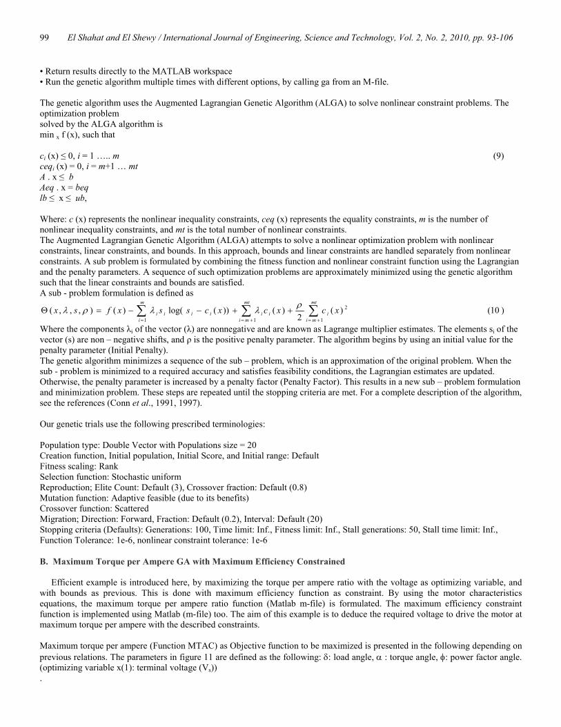
Population type: Double Vector with Populations size = 20 Creation function, Initial population, Initial Score, and Initial range: Default Fitness scaling: Rank Selection function: Stochastic uniform Reproduction; Elite Count: Default (3), Crossover fraction: Default (0.8) Mutation function: Adaptive feasible (due to its benefits) Crossover function: Scattered Migration; Direction: Forward, Fraction: Default (0.2), Interval: Default (20) Stopping criteria (Defaults): Generations: 100, Time limit: Inf., Fitness limit: Inf., Stall generations: 50, Stall time limit: Inf., Function Tolerance: 1e-6, nonlinear constraint tolerance: 1e-6 B. Maximum Torque per Ampere GA with Maximum Efficiency Constrained Efficient example is introduced here, by maximizing the torque per ampere ratio with the voltage as optimizing variable, and with bounds as previous. This is done with maximum efficiency function as constraint. By using the motor characteristics equations, the maximum torque per ampere ratio function (Matlab m-file) is formulated. The maximum efficiency constraint function is implemented using Matlab (m-file) too. The aim of this example is to deduce the required voltage to drive the motor at maximum torque per ampere with the described constraints. Maximum torque per ampere (Function MTAC) as Objective function to be maximized is presented in the following depending on previous relations. The parameters in figure 11 are defined as the following: δ: load angle, α : torque angle, φ: power factor angle. (optimizing variable x(1): terminal voltage (Vs)) .
El Shahat and El Shewy / International Journal of Engineering, Science and Technology, Vol. 2, No. 2, 2010, pp. 93-106
100
Figure11. Phasor diagram of the PMSM Function MTAC = f (x)
Vq = x(1) cos δ (11)
Vd = – x(1) sin δ (12) Vd and Vq are d and q axis stator voltages.
Iq = (Vq / Rs – C2 ( λaf + (Ld / Rs) Vd)) / C3 (13)
Id = Vd / Rs + C2 Lq Iq (14) C2=(ωr / Rs). C3=(1 + C2
2 Lq Ld). Id and Iq are d and q axis stator currents (neglect core loss).
Is = (Iq2 + Id
2)1/2 (15) Is : Stator current value.
α = tan– 1( Iq / Id ) (16)
The mutual flux linkage ( λm ), is the resultant of the rotor flux linkages and stator flux linkages. It is then given as
λm = ( λq2 + λd
2 )1/2. (Wb – Turn) (17)
The core loss, stray loss …etc are negligible, and so the copper loss Pcu is in Eq. (19).
Pcu = 3 Is2 Rs (18)
Pin , Pout are the input and output power. p.f = cos φ = cos ( π/2 + δ – α ) (19)
Pin = 3 x(1) Is p.f = (3/2) (Vd Id + Vq Iq) (20)
Pout = Pin – Pcu (21)
The efficiency η = Pout / Pin (22)
Torque per ampere output function (MTAC) = Te/I s (23)
Function constraints: This optimizing variable (x(1)) is bounded by [0 200]. The maximum efficiency function is used here as nonlinear constraint as follows:

El Shahat and El Shewy / International Journal of Engineering, Science and Technology, Vol. 2, No. 2, 2010, pp. 93-106
101
Function [c,ceq] = f (x) Using the machine’ characteristics relations in previous function
z = Efficiency = Pout / Pin c = [ ] ceq = [ z – 0.99999 ] The following figures present the various characteristics obtained from this function in comparable with such ones at rated terminal voltage. This is to show how much saving in energy.
0 0.2 0.4 0.6 0.8 1 1.2 1.4 1.6 1.8 20
0.1
0.2
0.3
0.4
0.5
0.6
0.7
0.8
Electromagnetic Torque (N.m)
Torque Per Ampere Ratio (N.m/Amp.)
Original Torque per Amp. RatioMaximum Torque per Amp. Ratio
Figure12. Maximum torque per ampere in both two cases
0 0.2 0.4 0.6 0.8 1 1.2 1.4 1.6 1.8 20
1
2
3
4
5
6
7
8
9
Electromagnetic Torque (N.m)
Stator C
urrent (A
mp.)
At Max. Torque per Amp.At Original Case
Figure13. Stator current value in both two cases

El Shahat and El Shewy / International Journal of Engineering, Science and Technology, Vol. 2, No. 2, 2010, pp. 93-106
102
0 0.2 0.4 0.6 0.8 1 1.2 1.4 1.6 1.8 20
500
1000
1500
2000
Electromagnetic Torque (N.m)
Input P
ower (W
att)
At Max. Torque per Amp.At Original Case
Figure14. Input power in both two cases
0 0.2 0.4 0.6 0.8 1 1.2 1.4 1.6 1.8 20
0.2
0.4
0.6
0.8
1
Electromagnetic Torque (N.m)
Efficiency
At Max. Torque per Amp. At Original Case
Figure15. Efficiency in both two cases
0 0.2 0.4 0.6 0.8 1 1.2 1.4 1.6 1.8 20
20
40
60
80
100
120
140
Electromagnetic Torque (N.m)
Required Voltage (V
olt)
Required Voltage 4th degree Eqn
Figure16. Required voltage to drive motor at maximum T per A
The relation between the electromagnetic torque (x-axis) and required voltage (y-axis) to drive the motor at maximum torque per ampere could be deduced using the curve fitting facility in Matlab as in equation (24).
y = 0.03*x^4 - 0.1*x^3 + 0.23*x^2 + 5*x + 1.2e+002 (24)

El Shahat and El Shewy / International Journal of Engineering, Science and Technology, Vol. 2, No. 2, 2010, pp. 93-106
103
From this trial’s figures; it is clear that, the performance characteristics like torque per ampere ratio, stator current, losses, input power and efficiency are highly improved. C. GA maximum efficiency constrained by GA maximum power factor This example improves motor performance by maximizing the efficiency with the voltage also as optimizing variable, and the same bounds as the previous example. This is done with GA maximum power factor as constraint also. By using the motor characteristics equations, the maximum efficiency function (Matlab m-file) is formulated. The maximum power factor constraint function is implemented using Matlab (m-file) too, and then using the Genetic technique. The aim of this example is to deduce the required voltage to drive the motor at maximum efficiency as possible with the described constraints. Maximum efficiency (Function MEFC) as objective function to be maximized is presented in the following depending on previous illustrated relations. (optimizing variable x(1): terminal Voltage (Vs)) . Function MEFC = f (x)
The same previous machine relations
MEFC = Efficiency = Pout/Pin
Function constraints: This optimizing variable (x(1)) is bounded by [0 200]. The maximum power factor function is used here as nonlinear constraint as follows: Function [c,ceq] = f (x) Using the machine characteristics relations in previous functions
zz = Power factor = cos ( π/2 + δ – α )
c = [ ] ceq = [ zz – 0.99999 ] The following figures present the various characteristics obtained from this function in comparison with such ones from original characteristics at rated voltage. This is to show how much performance improvement could be obtained using this example.
0 0.2 0.4 0.6 0.8 1 1.2 1.4 1.6 1.8 20
0.2
0.4
0.6
0.8
1
Electromagnetic Torque (N.m)
Efficiency
Original EfficiencyMax. Efficiency
Figure17. Efficiency in the two cases
El Shahat and El Shewy / International Journal of Engineering, Science and Technology, Vol. 2, No. 2, 2010, pp. 93-106
104
0 0.2 0.4 0.6 0.8 1 1.2 1.4 1.6 1.8 20
1
2
3
4
5
6
7
8
Electromagnetic Torque (N.m)
Stator C
urrent (A
mp.)
At Max. EfficiencyAt Org. Condition
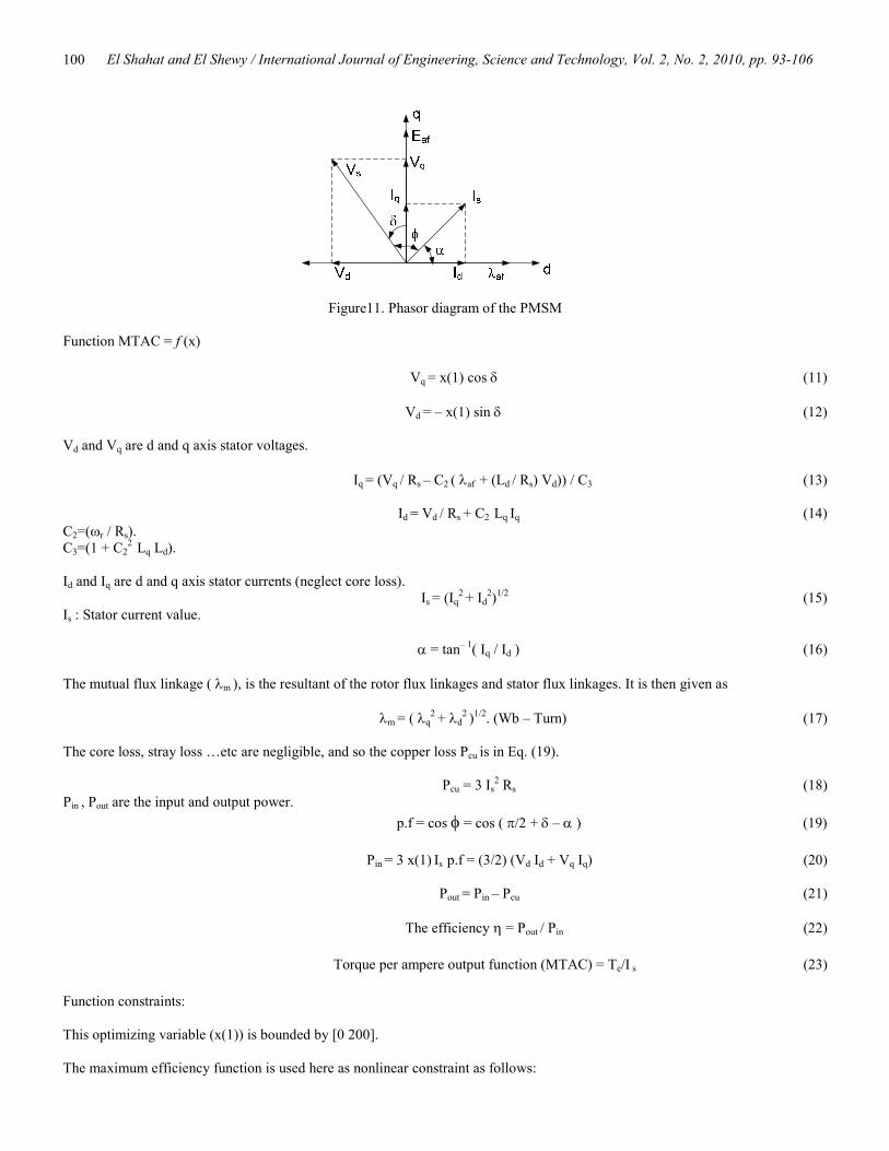
Figure18. Stator current in the two cases
0 0.2 0.4 0.6 0.8 1 1.2 1.4 1.6 1.8 20
500
1000
1500
2000
Electromagnetic Torque (N.m)
Input Pow
er (W
att)
At Max. EfficiencyAt Orig. Condition
Figure19. Input power in the two cases
0 0.2 0.4 0.6 0.8 1 1.2 1.4 1.6 1.8 20
20
40
60
80
100
120
Electromagnetic Torque (N.m)
Required Voltage (Volt)
Required Voltage 5th degree Eqn
Figure20. Required voltage to drive motor at GA maximum efficiency
By the same way, the relation between the electromagnetic torque (x-axis) and required voltage (y-axis) to drive the motor at maximum efficiency could be deduced using the curve fitting facility in Matlab as in equation (25).
y = - 0.916*x^5 + 4.97*x^4 - 9.85*x^3 + 8.58*x^2 - 3.04*x + 118 (25)

El Shahat and El Shewy / International Journal of Engineering, Science and Technology, Vol. 2, No. 2, 2010, pp. 93-106
105
The resulting figures in this trial is very satisfied for overall characteristics especially in efficiency, stator current, losses, and input power. 5. Conclusions This paper addresses new simple dynamic SPMSM modeling to can be used in many topics like in automotive applications, mechatronics, green energy applications, machine drives, etc. This simulation is done with the aid of MATLAB – Simulink to facilitate a good method for machine dynamic behavior prediction for the previous applications. The modeling procedures are described and simulation results are presented. This dynamic model is developed by coupling electrical equations and mechanical equations of the PMSM. Also, there are two proposed trials for performance improvement of PM synchronous motor using genetic algorithm. This idea is done by implementing two genetic algorithm functions with different constraints, same optimizing variable bounds and the same optimizing variable which is the voltage. The last one about GA maximum efficiency constrained by GA maximum power factor has the most powerful effect on all various machine characteristics. Second rank for performance improvement is in maximum torque per ampere GA with maximum efficiency constrained. All functions and simulations are implemented using Matlab environment with the aid of genetic algorithm toolbox. For each trial; the required voltage relation to drive the motor at the desired improved performance characteristics; with the aid of curve fitting facility in Matlab is presented. These algebraic equations may be used directly later without doing the genetic algorithm work each time. All various characteristics obtained are well depicted in the form of comparisons with such ones from original characteristics at rated voltage.
Appendix SPMSM parameters: Lq = 0.0115 H; Ld = 0.0115 H; λaf = 0.283; P = 4; Rs = 6.8 Ω; Vs = 200 V; Ns = 2000 rpm; B = 0.0005416; J = 0.0000144; Td = 0.1698 Acknowledgment I would like to thank Ms. Shaza M. Abd Al Menem for her effort in this research editing References
Bose B. K. 2002: Modern power electronics and AC drives. Prentice Hall, New Jersey. Conn A.R., Gould N. I. M., and Toint Ph. L. 1991. A globally convergent augmented lagrangian algorithm for optimization with
general constraints and simple bounds, SIAM Journal on Numerical Analysis, Vol. 28, No. 2, pp. 545–572. Conn A.R., Gould N. I. M., and Toint Ph. L. 1997. A globally convergent augmented lagrangian barrier algorithm for optimization
with general inequality constraints and simple bounds. Mathematics of Computation, Vol. 66, No. 217, pp. 261-288. Cvetkovski G., Petkovska L., Cundev M. and Gair S. 1998. Mathematical model of a permanent magnet axial field synchronous
motor for GA optimisation, in Proc. ICEM'98, Vol. 2/3, pp. 1172-1177. El Shahat A., and El Shewy H., 2009a. PM synchronous motor control strategies with their neural network regression functions, Journal of Electrical Systems, Vol. 5, No. 4, Dec, Paper No. 6.
El Shahat A., and El Shewy H., 2009b. PM synchronous motor genetic algorithm performance improvement for renewable energy applications, MDGEN11, International Conference on Millennium Development Goals (MDG): Role of ICT and other technologies, December 27 – 29, in Chennai, India.
El Shahat A., and El Shewy H., 2009c. Permanent magnet machines reliability appraisals and fault types review, EP-126, 13th International Conference on Aerospace Science & Aviation Technology, May 26 – 28, ASAT 2009 – Military Technical College, Cairo, Egypt.
El Shahat, A and El Shewy, H, 2009d. Neural unit for PM synchronous machine performance improvement used for renewable energy, Ref: 93, The Third Ain Shams University International Conference on Environmental Engineering (Ascee- 3), April 14-16, Cairo, Egypt.
El Shahat A., El Shewy H., 2009e. Neural unit for PM synchronous machine performance improvement used for renewable energy, Paper Ref.: 910, Global Conference on Renewable and Energy Efficiency for Desert Regions (GCREEDER2009), Amman, Jordan.
El Shahat A. and El Shewy H., 2010. High fundamental frequency PM synchronous motor design neural regression function, Journal of Electrical Engineering, Vol. 10, Edition 1, Article 10.1.14.
El Shahat A., A. Keyhani, and H. El Shewy, 2010. Spacecraft flywheel high speed PM synchronous motor design (classical & genetic), Journal of Theoretical and Applied Information Technology, Vol. 13, No. 1, pp. 83-100.
El Shewy, H and, El Shahat, A, 2009a. PM synchronous machine stabilization control for electric vehicle, Ref: 118, The Third Ain Shams University International Conference on Environmental Engineering (Ascee- 3), April 14-16, Cairo, Egypt.
El Shewy H., El Shahat A., 2009b. PM synchronous machine stabilization control for electric vehicle, Paper Ref.: 911, Global Conference on Renewable and Energy Efficiency for Desert Regions (GCREEDER2009), Amman, Jordan.
El Shewy H., and El Shahat A., 2009c. PM synchronous machine stabilization control for aircraft and spacecraft, CT-128, 13th International Conference on Aerospace Science & Aviation Technology, May 26 – 28, ASAT 2009 – Military Technical

El Shahat and El Shewy / International Journal of Engineering, Science and Technology, Vol. 2, No. 2, 2010, pp. 93-106
106
College, Cairo, Egypt. El Shewy H.M., Abd Al Kader F. E., El Kholy M., and El Shahat A., 2008. Dynamic modeling of permanent magnet synchronous
motor using MATLAB - Simulink” EE108, 6th International Conference on Electrical Engineering ICEENG 2008, 27-29 May, Military Technical College, Egypt.
Goldberg D.E., 1989. Genetic Algorithms in Search Optimisation and Machine Learning, Addison-Wesley Longman Publishing Co., Inc. Boston, MA, USA.
Holland H., 1995. Adaptation in Natural and Artificial Systems, Univ. of Michigan Press, Ann Arbor.. Jang-Mok K. and Seung-Ki S., 1997. Speed control of interior permanent magnet synchronous motor drive for the flux weakening
operation, IEEE Transactions on Industry Applications, Vol. 33, pp. 43-48. Jian-Xin X., Panda S. K., Ya-Jun P., Tong Heng L., and Lam B. H., 2004. A modular control scheme for PMSM speed control
with pulsating torque minimization, IEEE Transactions on Industrial Electronics, Vol. 51, pp. 526-536. Krishnan R., 2006. Electric Motor Drives: Modeling, Analysis & Control, Prentice Hall, Upper Saddle River, New Jersey. Mademlis C. and Margaris N., 2002. Loss minimization in vector-controlled interior permanent-magnet synchronous motor drives, IEEE Transactions on Industrial Electronics, Vol. 49, pp. 1344-1347.
Morimoto S., Tong Y., Takeda Y., and Hirasa T., 1994. Loss minimization control of permanent magnet synchronous motor drives, IEEE Transactions on Industrial Electronics, Vol. 41, pp. 511-517.
Onoda S. and Emadi A., 2004. PSIM-based modelling of automotive power systems: conventional, electric, and hybrid electric vehicles, IEEE Transactions on Vehicular Technology, Vol. 53, pp. 390-400.
Pillay P. and Krishnan R., 1988. Modeling of permanent magnet motor drives, IEEE Transactions on Industrial Electronics, Vol. 35, pp. 537-54.
Pillay P. and Krishnan R., 1989. Modeling, simulation, and analysis of permanent-magnet motor drives. I. The permanent-magnet synchronous motor drive, IEEE Transactions on Industry Applications, Vol. 25, pp. 265-273.
Rudolph G., 1994. Convergence analysis of canonical genetic algorithms, IEEE Transactions on Neural Networks, Vol. 5, No.1, pp. 96-101.
Wijenayake H.A. and Schmidt P. B., 1997. Modeling and analysis of permanent magnet synchronous motor by taking saturation and core loss into account, Proceedings 1997 International Conference on Power Electronics and Drive System, 26-29 May 1997, Vol. 2, pp. 530-534.
Biographical notes Adel El Shahat is a Research Scientist, ECE Dept., Mechatronics-Green Energy Lab, The Ohio State University, USA. His interests are: Electric Machines, Artificial Intelligence, Renewable Energy, Power System, Control Systems, PV cells, Power Electronics, and Smart Grids. He has more than 30 papers between journals and refereed conferences, and 15 abstracts and posters with one accepted book chapter. Member of IEEE, IEEE Computer Society, ASEE, IAENG, IACSIT, EES, WASET and ARISE. He gains honors and recognitions from OSU, USA 2009, Suez Canal University, Egypt, 2006, ARE 2000, and EES, 1999, Egypt. Hamed El Shewy currently is a Professor of Electrical Machines in the Electrical Power and Machines Department, Faculty of Engineering, Zagazig University, Zagazig, Egypt. He was the previous head of the same department. His research interests include Electric Machines, Power Systems, Power Electronics, and Electric Drives.
Received March 2010 Accepted April 2010 Final acceptance in revised form April 2010