pm5 panel meter optional output addendumaicpl.com.au/pdf/pm5opt.pdf · -arrr three extra relays...
TRANSCRIPT

PM5 Panel MeterOptional Output Addendum
AMALGAMATED INSTRUMENT CO ABN: 80 619 963 692
Unit 5, 28 Leighton Place Hornsby Telephone: +61 2 9476 2244 e-mail: [email protected] 2077 Australia Facsimile: +61 2 9476 2902 Internet: www.aicpl.com.au
Table of Contents
1 Introduction 3
2 Analog, dual analog outputs plus relay option(-I, -A, -II, -AA -IR, -AR, -IIR and -AAR options) 4
3 Transmitter supply option(-12, -R12, -I12, -A12, IR12 and -AR12 options) 5
4 One or three relay output option (-R, and -RRR options) 7
5 Three or six relay and analog output option(-R6 and -IR6, AR6, IRRR and ARRR options) 9
6 Serial and 4-20mA output option(-I2, -A2, -I2R, -A2R, -I4, -A4, -I4R and -A4R options) 10
7 Digital output option (-DP, -DP12, -DPR, -DPR12, -DN, -DN12, -DNR and-DNR12 options) 12
8 Serial and second relay output option(-2, -4, -2R and -4R options) 15
9 Serial plus three or five relay output option(-2R5, -2RRR, -4R5, and -4RRR options) 17
10 Serial communications commands 19
11 Ethernet plus RS232/RS485 plus datalogger 24
12 Analog PI control output 25
2 of 31 PM5OPTMAN-1.6-0

1 Introduction
This manual addendum contains information on the PM5 optional outputs. This manual is suppliedwhenever a PM5 panel meter is supplied with an optional output fitted. Refer to the standardmanual for the PM5 model purchased for information not covered in this addendum.
Note: Not all options are available on all instruments. Check the instruction manual or brochurefor the instrument to be used to see which options are available or contact supplier.
1.1 Input Output Configuration
If you need to alter the input or output configuration link settings proceed as follows:
Remove earth screwwhich passes through the
case then slide outthe printed circuit board
1. Remove the plug in terminalsfrom the rear of the instrument
2. Remove the 4 x self tapping screws fromthe back cover then remove the back coverby pulling it away from the instrument
3. Remove the earth screw which passesthrough the underside of the case thenslide out the board or boards
4. Configure the PCB links as requred, see appropriate chapter
5. Slide PCB back into case
6. Replace the earth screw which passes through the case
7. Refit the back cover and fix with the self tapping screws
8. Plug the terminal strips back into the rear of the instrument
PM5OPTMAN-1.6-0 3 of 31

2 Analog, dual analog outputs plus relay option
(-I, -A, -II, -AA -IR, -AR, -IIR and -AAR options)
This chapter deals with the the 12 and 16 bit single and dual isolated analog output boards. Theseboards may also be optionally fitted with a relay. The relay will revert to the normally open (N/O)contact being open when power is removed.
Note: the 12 bit analog output option is 4-20mA output only.
Option code Options fitted to the board
-I Single isolated analog output 12 bit 4–20mA only-A Single isolated analog output 16 bit 4–20mA, 0–10V (or 12.5 bit 0–1VDC)-II Dual isolated analog output 12 bit 4–20mA only-AA Dual isolated analog output 16 bit 4–20mA, 0–10V (or 12.5 bit 0–1VDC)-IR Single isolated analog output 12 bit 4–20mA only plus relay (form C, rated at
240VAC, 3A into resistive load)-AR Single isolated analog output 16 bit 4–20mA, 0–10V (or 12.5 bit 0–1VDC) only
plus relay (form C, rated at 240VAC, 3A into resistive load)-IIR Dual isolated analog output 12 bit 4–20mA only plus relay (form C, rated at
240VAC, 3A into resistive load)-AAR Dual isolated analog output 16 bit 4–20mA, 0–10V (or 12.5 bit 0–1VDC) only
plus relay (form C, rated at 240VAC, 3A into resistive load)
2.1 Electrical Connections
All electrical connections are at the rear of the instrument. The plug in screw connectors usedallow wire of up to 2.5mm2. Refer to “Electrical Installation” chapter in the main PM5 manual forgeneral information on electrical connections.
4 of 31 PM5OPTMAN-1.6-0
3 Transmitter supply option
(-12, -R12, -I12, -A12, IR12 and -AR12 options)
This chapter deals with the the transmitter supply option circuit board. The transmitter supplymay be fitted on its own or with combinations of relay and analog retransmission. The choicebetween 24VDC (±12V) and 10V (±5V) is software selectable. The relay will revert to the normallyopen (N/O) contact being open when power is removed.
Option code Options fitted to the board
-12 24VDC (±12V) or 10V (±5V) isolated and regulated transmitter supply ratedat 20mA max.
-R12 24VDC (±12V) or 10V (±5V) isolated and regulated transmitter supply ratedat 20mA max. plus extra relay (form C, rated at 240VAC, 3A into resistiveload)
-12I 12 bit 4–20mA only analog retransmission plus 24VDC (±12V) or 10V (±5V)isolated and regulated transmitter supply rated at 20mA max.
-12A 16 bit 4–20mA, 0–10VDC (or 12.5 bit 0–1VDC) analog retransmission plus24VDC (±12V) or 10V (±5V) isolated and regulated transmitter supply ratedat 20mA max.
-12IR 24VDC (±12V) or 10V (±5V) isolated and regulated transmitter supply ratedat 20mA max. plus 12 bit 4–20mA only analog retransmission plus extra relay(form C, rated at 240VAC, 3A into resistive load)
-12AR 24VDC (±12V) or 10V (±5V) isolated and regulated transmitter supply ratedat 20mA max. plus 16 bit 4–20mA, 0–10VDC (or 12.5 bit 0–1VDC) analogretransmission plus extra relay (form C, rated at 240VAC, 3A into resistiveload)
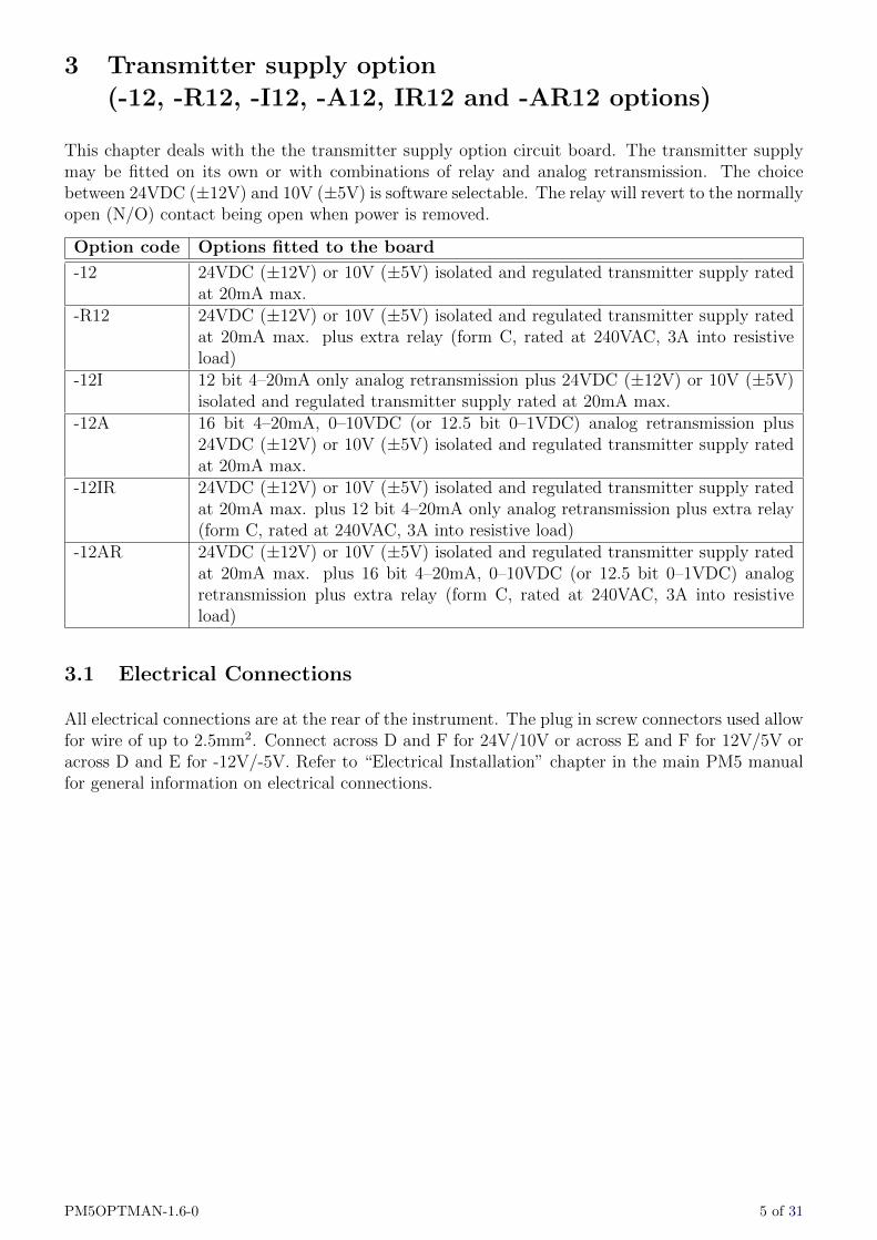
3.1 Electrical Connections
All electrical connections are at the rear of the instrument. The plug in screw connectors used allowfor wire of up to 2.5mm2. Connect across D and F for 24V/10V or across E and F for 12V/5V oracross D and E for -12V/-5V. Refer to “Electrical Installation” chapter in the main PM5 manualfor general information on electrical connections.
PM5OPTMAN-1.6-0 5 of 31
6 of 31 PM5OPTMAN-1.6-0
4 One or three relay output option (-R, and -RRR options)
This chapter deals with the the one or three extra relay output options.
Option code Options fitted to the board
-R Second relay output (form C, rated at 240VAC, 5A into resistive load)-RRR Second, third and fourth extra relay output (form C, rated at 240VAC, 5A into
resistive load)
All relays will revert to the normally open (N/O) contacts being open circuit when power is removed.
An alternative solid state relay driver output version (switches 24VDC to drive an external solidstate relay (not supplied)) is available to order.
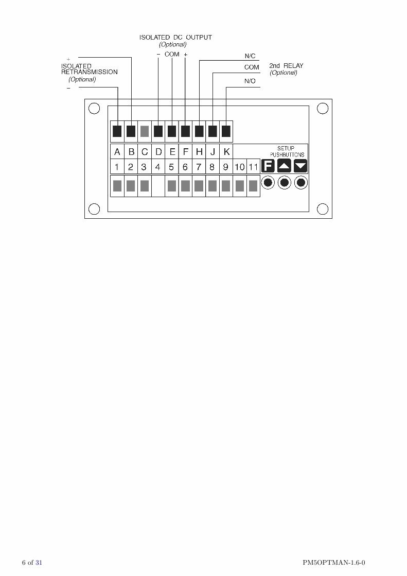
4.1 Electrical Connections
All electrical connections are at the rear of the instrument. The plug in screw connectors usedallow for wire of up to 2.5mm2. Refer to “Electrical Installation” chapter in the main PM5 manualfor general information on electrical connections.
PM5OPTMAN-1.6-0 7 of 31

8 of 31 PM5OPTMAN-1.6-0
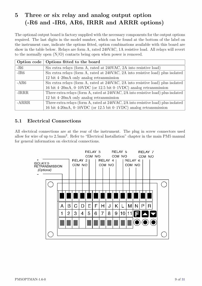
5 Three or six relay and analog output option
(-R6 and -IR6, AR6, IRRR and ARRR options)
The optional output board is factory supplied with the necessary components for the output optionsrequired. The last digits in the model number, which can be found at the bottom of the label onthe instrument case, indicate the options fitted, option combinations available with this board areshow in the table below. Relays are form A, rated 240VAC, 1A resistive load. All relays will revertto the normally open (N/O) contacts being open when power is removed.
Option code Options fitted to the board
-R6 Six extra relays (form A, rated at 240VAC, 2A into resistive load)-IR6 Six extra relays (form A, rated at 240VAC, 2A into resistive load) plus isolated
12 bit 4–20mA only analog retransmission-AR6 Six extra relays (form A, rated at 240VAC, 2A into resistive load) plus isolated
16 bit 4–20mA, 0–10VDC (or 12.5 bit 0–1VDC) analog retransmission-IRRR Three extra relays (form A, rated at 240VAC, 2A into resistive load) plus isolated
12 bit 4–20mA only analog retransmission-ARRR Three extra relays (form A, rated at 240VAC, 2A into resistive load) plus isolated
16 bit 4-20mA, 0–10VDC (or 12.5 bit 0–1VDC) analog retransmission
5.1 Electrical Connections
All electrical connections are at the rear of the instrument. The plug in screw connectors usedallow for wire of up to 2.5mm2. Refer to “Electrical Installation” chapter in the main PM5 manualfor general information on electrical connections.
PM5OPTMAN-1.6-0 9 of 31

6 Serial and 4-20mA output option
(-I2, -A2, -I2R, -A2R, -I4, -A4, -I4R and -A4R options)
This addendum covers instruments with the isolated serial/isolated analog output board. Thisboard allows output of either RS232 or RS485 plus 4–20mA plus a second relay. The last digits inthe model number, which can be found at the bottom of the label on the instrument case, indicatethe options fitted, option combinations available with this board are show in the table below. Note:Voltage output is not available with this board. Relays are form C, rated 240VAC, 5A resistiveload. The relay will revert to the normally open (N/O) contact being open when power is removed.
Option code Options fitted to the board
-2I Isolated RS232 serial communication plus isolated 12 bit 4–20mA only output-2A Isolated 16 bit 4–20mA, 0–10VDC (or 12.5 bit 0–1 VDC) output plus isolated
RS232 serial communication-2IR Isolated RS232 serial communication plus isolated 12 bit 4–20mA only output
plus second relay (form C, rated at 240VAC, 3A into resistive load)-2AR Isolated RS232 serial communication plus isolated 16 bit 4–20mA, 0–10VDC (or
12.5 bit 0–1 VDC) output plus second relay (form C, rated at 240VAC, 3A intoresistive load)
-4I Isolated RS485 serial communication plus isolated 12 bit 4–20mA only output-4A Isolated RS485 serial communication plus isolated 16 bit 4–20mA, 0–10VDC (or
12.5 bit 0–1 VDC) output-4IR Isolated RS485 serial communication plus isolated 12 bit 4–20mA only output
plus second relay (form C, rated at 240VAC, 3A into resistive load)-4AR Isolated RS485 serial communication plus isolated 16 bit 4–20mA, 0–10VDC (or
12.5 bit 0–1 VDC) output plus second relay (form C, rated at 240VAC, 3A intoresistive load)
6.1 Electrical Connections
All electrical connections are at the rear of the instrument. The plug in screw connectors usedallow for wire of up to 2.5mm2. Refer to “Electrical Installation” chapter in the main PM5 manualfor general information on electrical connections.
10 of 31 PM5OPTMAN-1.6-0
PM5OPTMAN-1.6-0 11 of 31

7 Digital output option (-DP, -DP12, -DPR, -DPR12, -
DN, -DN12, -DNR and -DNR12 options)
This chapter deals with the the isolated digital output option circuit board. The digital output isavailable in PNP or NPN versions and each may be fitted on its own or with combinations of relayand excitation voltage. The choice of excitation voltage between 24VDC and 5VDC is softwareselectable. The relay will revert to the normally open (N/O) contact being open when power isremoved.
Option code Options fitted to the board
-DP 16 bit PNP binary or BCD output-DP12 16 bit PNP binary or BCD output plus DC excitation voltage selectable as 5V
(100mA max) or 24V (20mA max)-DPR 16 bit PNP binary or BCD output plus extra relay (form A, 3A @ 240VAC)-DP12R 16 bit PNP binary or BCD output plus DC excitation voltage selectable as 5V
(100mA max) or 24V (20mA max) plus extra relay (form A, 3A @ 240VAC)-DN 16 bit NPN binary or BCD output-DN12 16 bit NPN binary or BCD output plus DC excitation voltage selectable as 5V
(100mA max) or 24V (20mA max)-DNR 16 bit NPN binary or BCD output plus extra relay (form A, 3A @ 240VAC)-DN12R 16 bit NPN binary or BCD output plus DC excitation voltage selectable as 5V
(100mA max) or 24V (20mA max) plus extra relay (form A, 3A @ 240VAC)
7.1 Electrical Connections
All electrical connections are at the rear of the instrument. Refer to “Electrical Installation”chapter in the main PM5 manual for general information on electrical connections.
12 of 31 PM5OPTMAN-1.6-0
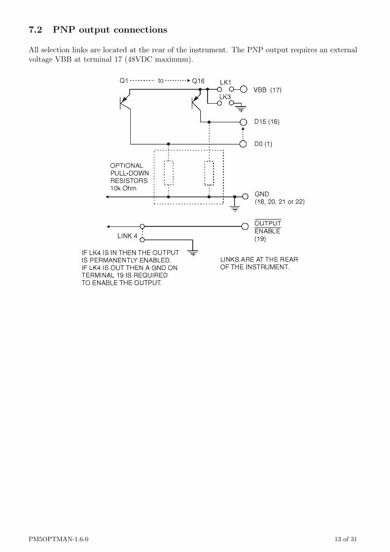
7.2 PNP output connections
All selection links are located at the rear of the instrument. The PNP output requires an externalvoltage VBB at terminal 17 (48VDC maximum).
PM5OPTMAN-1.6-0 13 of 31

7.3 NPN output connections
All selection links are located at the rear of the instrument. If no voltage is available at the signalinput of the receiving device then optional pull up resistors can be fitted and the voltage suppliedfrom 5V internally (via LK2) or via an externally applied voltage VIN at terminal 17 (via LK1,48VDC maximum).
14 of 31 PM5OPTMAN-1.6-0

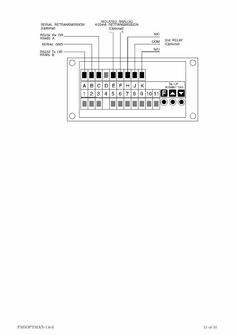
8 Serial and second relay output option
(-2, -4, -2R and -4R options)
The information provided in this section relates to PM5 panel meters with isolated RS232 orisolated RS485 outputs using the optional serial output board. The relay is form A, rated 240VAC,5A resistive load. The relay will revert to the normally open (N/O) contact being open when poweris removed.
Option code Options fitted to the board
-2 Isolated RS232 serial communication-4 Isolated RS485 serial communication-2R Isolated RS232 serial communication and second relay (form C, rated at
240VAC, 3A into resistive load)-4R Isolated RS485 serial communication and second relay (form C, rated at
240VAC, 3A into resistive load)
8.1 Electrical Connections
All electrical connections are at the rear of the instrument. The plug in screw connectors usedallow for wire of up to 2.5mm2. Refer to “Electrical Installation” chapter in the main PM5 manualfor general information on electrical connections.
PM5OPTMAN-1.6-0 15 of 31
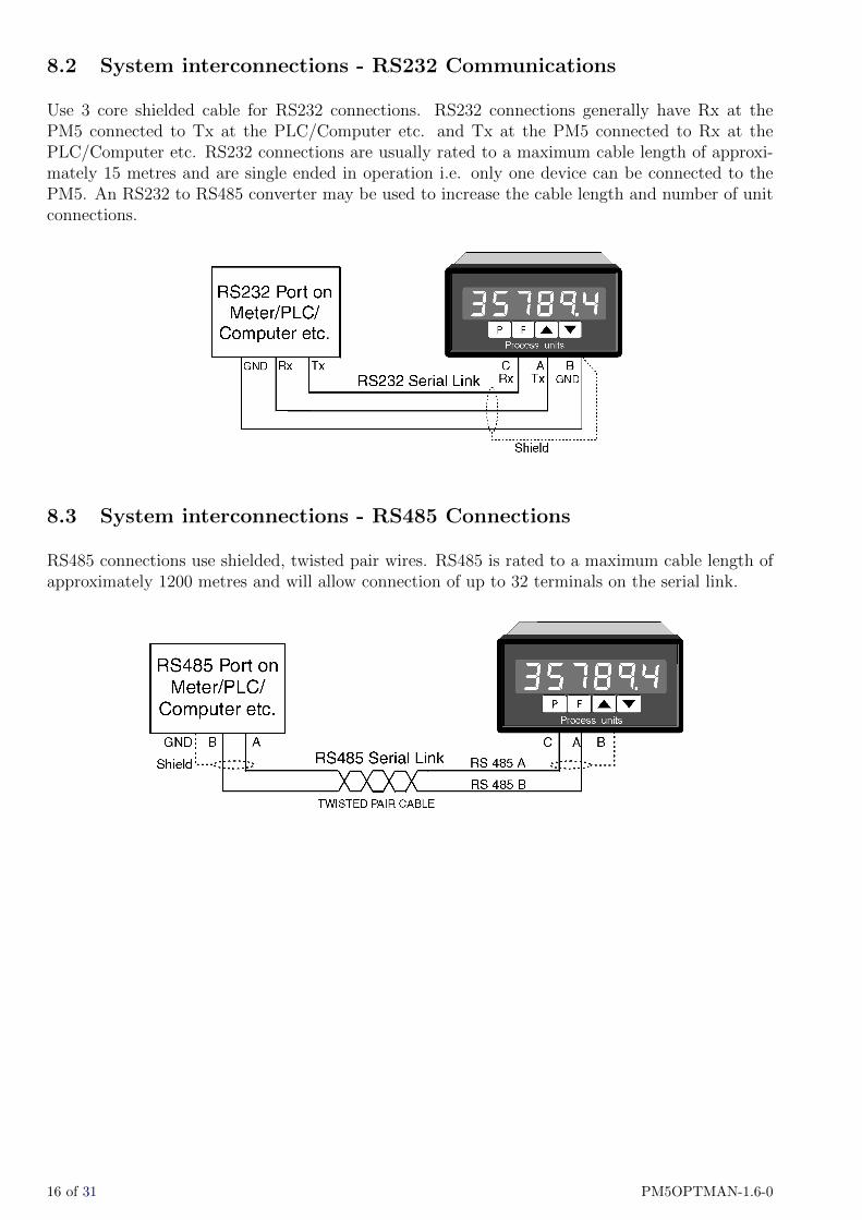
8.2 System interconnections - RS232 Communications
Use 3 core shielded cable for RS232 connections. RS232 connections generally have Rx at thePM5 connected to Tx at the PLC/Computer etc. and Tx at the PM5 connected to Rx at thePLC/Computer etc. RS232 connections are usually rated to a maximum cable length of approxi-mately 15 metres and are single ended in operation i.e. only one device can be connected to thePM5. An RS232 to RS485 converter may be used to increase the cable length and number of unitconnections.
8.3 System interconnections - RS485 Connections
RS485 connections use shielded, twisted pair wires. RS485 is rated to a maximum cable length ofapproximately 1200 metres and will allow connection of up to 32 terminals on the serial link.
16 of 31 PM5OPTMAN-1.6-0

9 Serial plus three or five relay output option
(-2R5, -2RRR, -4R5, and -4RRR options)
This chapter deals with the the serial plus three or five extra relay output options.
Option code Options fitted to the board
-2R5 RS232 and 5 extra relay output (form A, rated at 240VAC, 2A into resistiveload)
-2RRR RS232 and 3 extra relay output (form A, rated at 240VAC, 2A into resistiveload)
-4R5 RS485 and 5 extra relay output (form A, rated at 240VAC, 2A into resistiveload)
-4RRR RS485 and 3 extra relay output (form A, rated at 240VAC, 2A into resistiveload)
All relays will revert to the normally open (N/O) contacts being open circuit when power is removed.
9.1 Electrical Connections
All electrical connections are at the rear of the instrument. The plug in screw connectors usedallow for wire of up to 2.5mm2. Refer to “Electrical Installation” chapter in the main PM5 manualfor general information on electrical connections.
PM5OPTMAN-1.6-0 17 of 31

9.2 System interconnections - RS232 Communications
Use 3 core shielded cable for RS232 connections. RS232 connections generally have Rx at thePM5 connected to Tx at the PLC/Computer etc. and Tx at the PM5 connected to Rx at thePLC/Computer etc. RS232 connections are usually rated to a maximum cable length of approxi-mately 15 metres and are single ended in operation i.e. only one device can be connected to thePM5. An RS232 to RS485 converter may be used to increase the cable length and number of unitconnections.
9.3 System interconnections - RS485 Connections
RS485 connections use shielded, twisted pair wires. RS485 is rated to a maximum cable length ofapproximately 1200 metres and will allow connection of up to 32 terminals on the serial link.
18 of 31 PM5OPTMAN-1.6-0
10 Serial communications commands
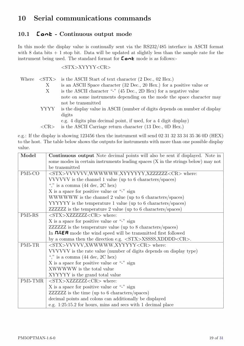
10.1 Cont - Continuous output mode
In this mode the display value is continually sent via the RS232/485 interface in ASCII formatwith 8 data bits + 1 stop bit. Data will be updated at slightly less than the sample rate for theinstrument being used. The standard format for Cont mode is as follows:-
<STX>XYYYY<CR>
Where <STX> is the ASCII Start of text character (2 Dec., 02 Hex.)X is an ASCII Space character (32 Dec., 20 Hex.) for a positive value orX is the ASCII character “-” (45 Dec., 2D Hex) for a negative value
note on some instruments depending on the mode the space character maynot be transmitted
YYYY is the display value in ASCII (number of digits depends on number of displaydigitse.g. 4 digits plus decimal point, if used, for a 4 digit display)
<CR> is the ASCII Carriage return character (13 Dec., 0D Hex.)
e.g.: If the display is showing 123456 then the instrument will send 02 31 32 33 34 35 36 0D (HEX)to the host. The table below shows the outputs for instruments with more than one possible displayvalue.
Model Continuous output Note decimal points will also be sent if displayed. Note insome modes in certain instruments leading spaces (X in the strings below) may notbe transmitted
PM5-CO <STX>VVVVVV,WWWWWW,XYYYYYY,XZZZZZZ<CR> where:VVVVVV is the channel 1 value (up to 6 characters/spaces)“,” is a comma (44 dec, 2C hex)X is a space for positive value or “-” signWWWWWW is the channel 2 value (up to 6 characters/spaces)YYYYYY is the temperature 1 value (up to 6 characters/spaces)ZZZZZZ is the temperature 2 value (up to 6 characters/spaces)
PM5-RS <STX>XZZZZZZ<CR> where:X is a space for positive value or “-” signZZZZZZ is the temperature value (up to 8 characters/spaces)In NMEA mode the wind speed will be transmitted first followedby a comma then the direction e.g. <STX>XSSSS,XDDDD<CR>.
PM5-TR <STX>VVVVV,XWWWWW,XYYYYY<CR> where:VVVVVV is the rate value (number of digits depends on display type)“,” is a comma (44 dec, 2C hex)X is a space for positive value or “-” signXWWWWW is the total valueXYYYYY is the grand total value
PM5-TMR <STX>XZZZZZZ<CR> where:X is a space for positive value or “-” signZZZZZZ is the time (up to 6 characters/spaces)decimal points and colons can additionally be displayede.g. 1:25:15.2 for hours, mins and secs with 1 decimal place
PM5OPTMAN-1.6-0 19 of 31
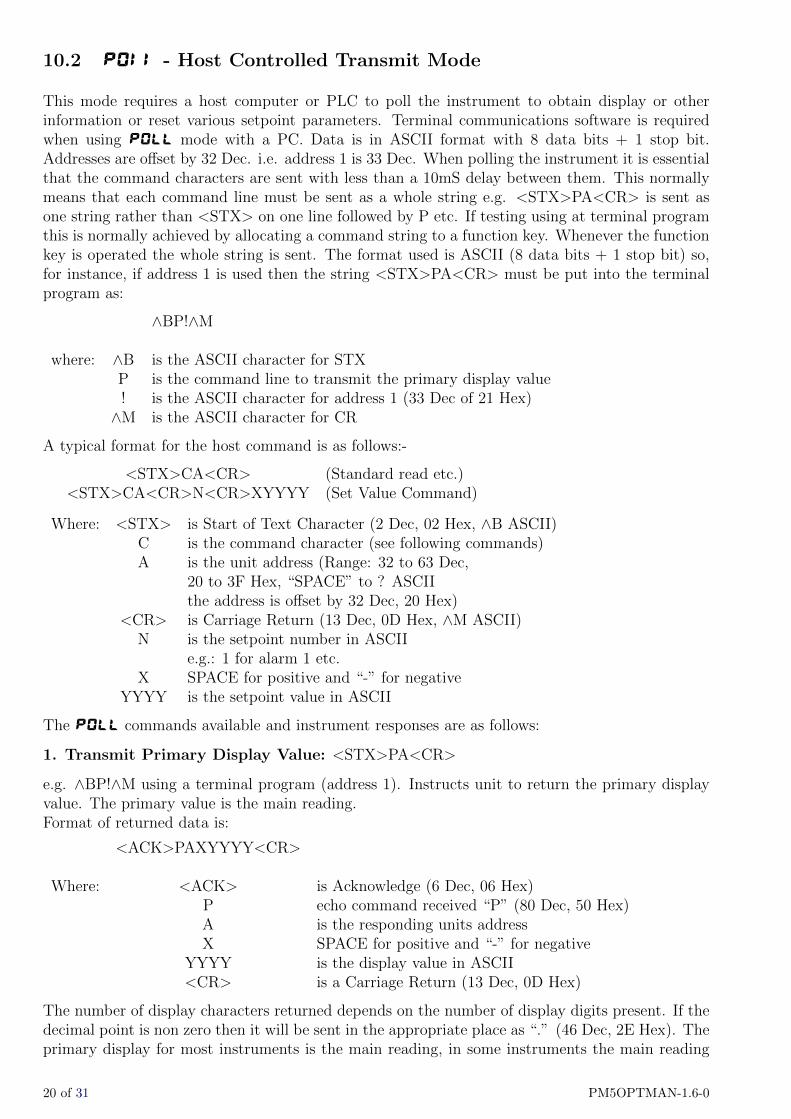
10.2 POII - Host Controlled Transmit Mode
This mode requires a host computer or PLC to poll the instrument to obtain display or otherinformation or reset various setpoint parameters. Terminal communications software is requiredwhen using POLL mode with a PC. Data is in ASCII format with 8 data bits + 1 stop bit.Addresses are offset by 32 Dec. i.e. address 1 is 33 Dec. When polling the instrument it is essentialthat the command characters are sent with less than a 10mS delay between them. This normallymeans that each command line must be sent as a whole string e.g. <STX>PA<CR> is sent asone string rather than <STX> on one line followed by P etc. If testing using at terminal programthis is normally achieved by allocating a command string to a function key. Whenever the functionkey is operated the whole string is sent. The format used is ASCII (8 data bits + 1 stop bit) so,for instance, if address 1 is used then the string <STX>PA<CR> must be put into the terminalprogram as:
∧BP!∧M
where: ∧B is the ASCII character for STXP is the command line to transmit the primary display value! is the ASCII character for address 1 (33 Dec of 21 Hex)∧M is the ASCII character for CR
A typical format for the host command is as follows:-
<STX>CA<CR> (Standard read etc.)<STX>CA<CR>N<CR>XYYYY (Set Value Command)
Where: <STX> is Start of Text Character (2 Dec, 02 Hex, ∧B ASCII)C is the command character (see following commands)A is the unit address (Range: 32 to 63 Dec,
20 to 3F Hex, “SPACE” to ? ASCIIthe address is offset by 32 Dec, 20 Hex)
<CR> is Carriage Return (13 Dec, 0D Hex, ∧M ASCII)N is the setpoint number in ASCII
e.g.: 1 for alarm 1 etc.X SPACE for positive and “-” for negative
YYYY is the setpoint value in ASCII
The POLL commands available and instrument responses are as follows:
1. Transmit Primary Display Value: <STX>PA<CR>
e.g. ∧BP!∧M using a terminal program (address 1). Instructs unit to return the primary displayvalue. The primary value is the main reading.Format of returned data is:
<ACK>PAXYYYY<CR>
Where: <ACK> is Acknowledge (6 Dec, 06 Hex)P echo command received “P” (80 Dec, 50 Hex)A is the responding units addressX SPACE for positive and “-” for negative
YYYY is the display value in ASCII<CR> is a Carriage Return (13 Dec, 0D Hex)
The number of display characters returned depends on the number of display digits present. If thedecimal point is non zero then it will be sent in the appropriate place as “.” (46 Dec, 2E Hex). Theprimary display for most instruments is the main reading, in some instruments the main reading
20 of 31 PM5OPTMAN-1.6-0
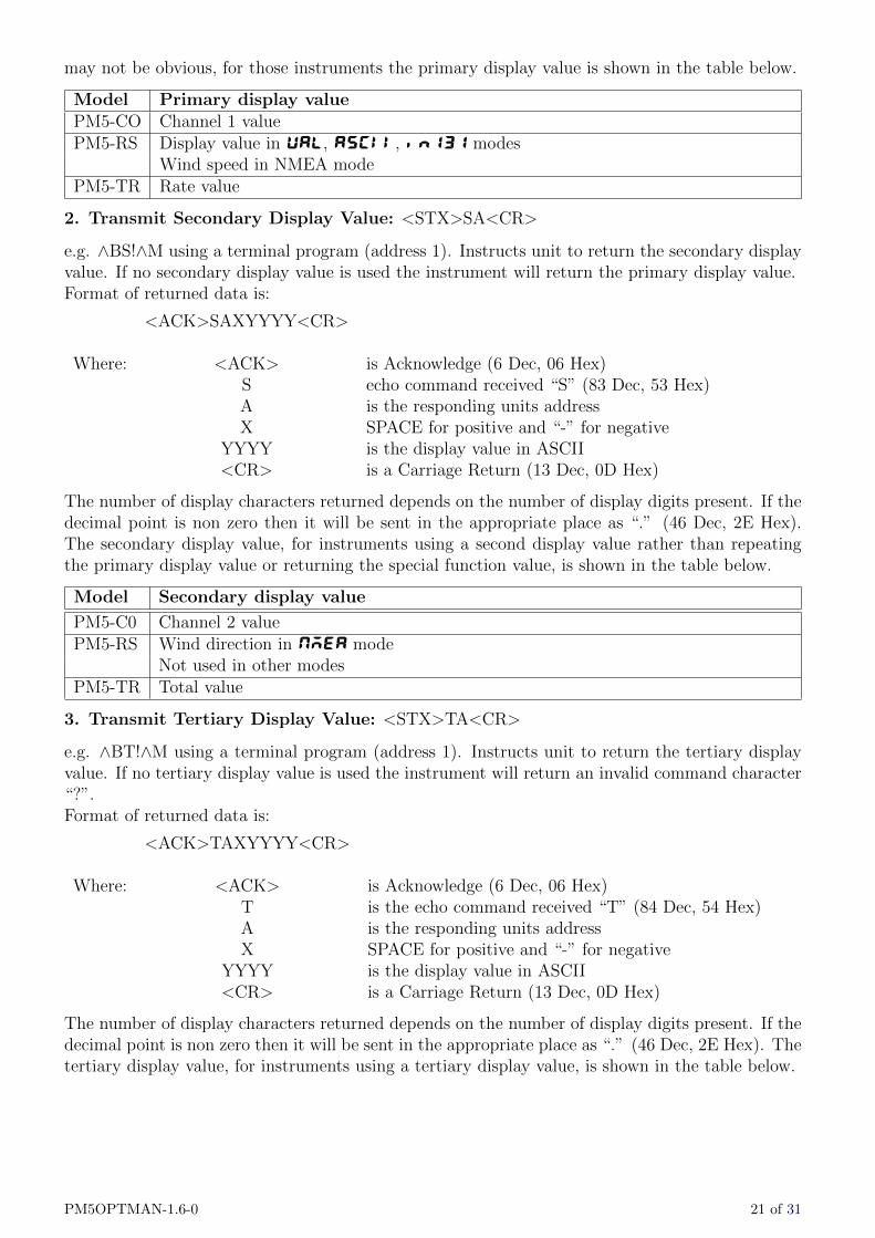
may not be obvious, for those instruments the primary display value is shown in the table below.
Model Primary display valuePM5-CO Channel 1 valuePM5-RS Display value in UAL, ASCII, in131 modes
Wind speed in NMEA modePM5-TR Rate value
2. Transmit Secondary Display Value: <STX>SA<CR>
e.g. ∧BS!∧M using a terminal program (address 1). Instructs unit to return the secondary displayvalue. If no secondary display value is used the instrument will return the primary display value.Format of returned data is:
<ACK>SAXYYYY<CR>
Where: <ACK> is Acknowledge (6 Dec, 06 Hex)S echo command received “S” (83 Dec, 53 Hex)A is the responding units addressX SPACE for positive and “-” for negative
YYYY is the display value in ASCII<CR> is a Carriage Return (13 Dec, 0D Hex)
The number of display characters returned depends on the number of display digits present. If thedecimal point is non zero then it will be sent in the appropriate place as “.” (46 Dec, 2E Hex).The secondary display value, for instruments using a second display value rather than repeatingthe primary display value or returning the special function value, is shown in the table below.
Model Secondary display value
PM5-C0 Channel 2 valuePM5-RS Wind direction in NMEA mode
Not used in other modesPM5-TR Total value
3. Transmit Tertiary Display Value: <STX>TA<CR>
e.g. ∧BT!∧M using a terminal program (address 1). Instructs unit to return the tertiary displayvalue. If no tertiary display value is used the instrument will return an invalid command character“?”.Format of returned data is:
<ACK>TAXYYYY<CR>
Where: <ACK> is Acknowledge (6 Dec, 06 Hex)T is the echo command received “T” (84 Dec, 54 Hex)A is the responding units addressX SPACE for positive and “-” for negative
YYYY is the display value in ASCII<CR> is a Carriage Return (13 Dec, 0D Hex)
The number of display characters returned depends on the number of display digits present. If thedecimal point is non zero then it will be sent in the appropriate place as “.” (46 Dec, 2E Hex). Thetertiary display value, for instruments using a tertiary display value, is shown in the table below.
PM5OPTMAN-1.6-0 21 of 31

Model Tertiary display value
PM5-C0 Temperature 1 valuePM5-RS Not usedPM5-TR Grand total value
4. Transmit Quad Display Value: <STX>QA<CR>
e.g. ∧BQ!∧M using a terminal program (address 1). Instructs unit to return the quad displayvalue. If no quad display value is used the instrument will return an invalid command character“?”.Format of returned data is:
<ACK>TAXYYYY<CR>
Where: <ACK> is Acknowledge (6 Dec, 06 Hex)Q is the echo command received “Q” (81 Dec, 51 Hex)A is the responding units addressX SPACE for positive and “-” for negative
YYYY is the display value in ASCII<CR> is a Carriage Return (13 Dec, 0D Hex)
The number of display characters returned depends on the number of display digits present. If thedecimal point is non zero then it will be sent in the appropriate place as “.” (46 Dec, 2E Hex). Thetertiary display value, for instruments using a tertiary display value, is shown in the table below.
Model Quad display value
PM5-C0 Temperature 2 valuePM5-RS Not usedPM5-TR Not used
5. Transmit Instrument Details and Software Version: <STX>IA<CR>
e.g. ∧BI!∧M using a terminal program (address 1) Instructs unit to return the details and softwareversion number of the instrument.Format of returned data is:-
<ACK>IA<c> YYYY AIC XXXXX ZZZ.Z <CR>
Where: <ACK> is Acknowledge (6 Dec, 06 Hex)I is echo command received “I” (73 Dec, 49 Hex)A is the responding units address
<c> is a copyright symbolYYYY is the year of production
AIC is the manufacturer nameXXXX is the input circuit identifierZZZ.Z is the software version
10. Invalid Command
If the command received from the host is not valid then the unit will return the following:-
<ACK>?A<CR>
Where: <ACK> is Acknowledge (6 Dec, 06 Hex)? is the character “?” (63 Dec, 3F Hex)A is the responding units address
<CR> is a Carriage Return (13 Dec, 0D Hex)
22 of 31 PM5OPTMAN-1.6-0

If the address received from the host does not match the units address then the unit will notrespond at all.
Host Timing Requirements for RS485 Operation:
RS485 operation requires the host to switch the RS485 transceiver to transmit before a commandis sent. The instrument is capable of replying after 1 to 2 milliseconds. Therefore the host shouldswitch the RS485 transceiver back to receive mode within 0.5 milliseconds after the last characterof the command has been sent to ensure correct operation.
PM5OPTMAN-1.6-0 23 of 31
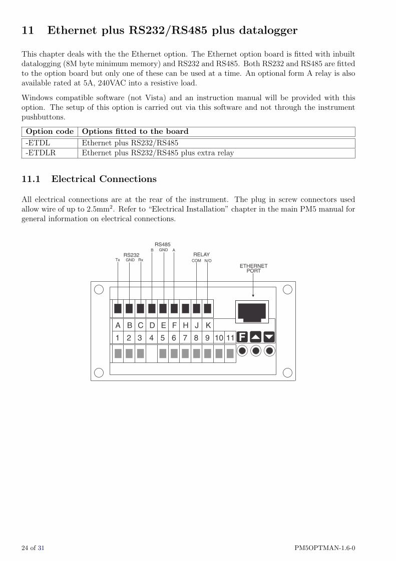
11 Ethernet plus RS232/RS485 plus datalogger
This chapter deals with the the Ethernet option. The Ethernet option board is fitted with inbuiltdatalogging (8M byte minimum memory) and RS232 and RS485. Both RS232 and RS485 are fittedto the option board but only one of these can be used at a time. An optional form A relay is alsoavailable rated at 5A, 240VAC into a resistive load.
Windows compatible software (not Vista) and an instruction manual will be provided with thisoption. The setup of this option is carried out via this software and not through the instrumentpushbuttons.
Option code Options fitted to the board
-ETDL Ethernet plus RS232/RS485-ETDLR Ethernet plus RS232/RS485 plus extra relay
11.1 Electrical Connections
All electrical connections are at the rear of the instrument. The plug in screw connectors usedallow wire of up to 2.5mm2. Refer to “Electrical Installation” chapter in the main PM5 manual forgeneral information on electrical connections.
A B HC D E F J K
1 2 3 4 5 6 7 8 9 10 11
B
Tx COM
GND
GND N/O
A
RxRELAY
ETHERNETPORT
RS485
RS232
F^v
24 of 31 PM5OPTMAN-1.6-0

12 Analog PI control output
PI control functions will only be seen if PI control software is available for the instrument and ifthe optional isolated analog or dual isolated analog output is fitted.
The PI (proportional + integral) control output may be configured for proportional only (i.e.integral gain set to 0.000) or proportional + integral control. Using the control function settingsdescribed below the instrument will vary the control output signal in such a way that the processbeing monitored is kept as close as possible to the control setpoint. The control may be turned onor off via the function. When the function is set toOFF the output will act as a retransmissionoutput rather than a control output and the PI control functions will not be seen. When set toon the PI control functions will be seen but the standard retransmission functions (e.g. and )will not. The best PI control results are usually achieved by initially configuring as a proportionalonly controller and introducing the Integral control once stable results have been obtained fromproportional only control.
12.1 Proportional control output
For proportional only control the output is found from:
Proportional control output = Error × Proportional gain + Offset
Where the Error is defined by the function, the Proportional gain is set by the function and theOffset is set by the function.
12.2 Analog output 1 PI control on or off
Display: P.CtIRange: No or YESDefault Value: No
Allows selection of retransmission (No) or PI control analog output (YES). If set to No then theanalog output will operate as a retransmission output using the limits set at the Lo and HiGHfunctions. If set to YES then the analog output will operate as a PI control output and the PIcontrol functions will appear.
To set the selection go to the function, pressF and when you see the decimal points flash use the^ or v push buttons to select the required setting then press F to accept this selection.
12.3 Analog output 1 PI control setpoint
Display: SEtPRange: Any display valueDefault Value: 0
Allows selection of the PI control setpoint.
The control setpoint is set to the value in displayed units required for control of the process. Thecontroller will attempt to vary the control output to keep the process variable at the setpoint.
PM5OPTMAN-1.6-0 25 of 31

Process above
setpoint
Process below
setpoint
Process at
setpoint
SETPOINT
PROCESS
TIME
To set the selection go to the function, press F and when you see a digit of the value flash usethe ^ or v push buttons to set the required value then press F to accept this selection.
12.4 Analog output 1 PI control span
Display: SPAnRange: Any display valueDefault Value: 1000
Allows selection of the PI control span. The function of the control span is to define the limitto which the proportional control values will relate. The span value defines the range over whichthe input must change to cause a 100% change in the control output when the proportional gainis set to 1.000. This function affects the overall gain of the controller and is normally set to theprocess value limits that the controller requires for normal operation. For example if the controlsetpoint () is 50.0 and the is 15 then an error of 15 from the setpoint will cause a 100% changein proportional control output.
For example, assuming that the control output is a 4-20mA signal, with at 50.0, at 15.0, at1.000 and C.PO at 0.000 a display reading of 35.0 or lower ( – ) the control output will beat 100% i.e. 20mA. The control output will then gradually fall as the display value reaches thesetpoint.
To set the value go to the function, press F and when you see a digit of the value flash use the^ or v push buttons to set the required value then press F to accept this selection.
12.5 Analog output 1 PI control proportional gain
Display: P.gRange: -32.768 to 32.767Default Value: 1.000
Allows selection of the PI control proportional gain.
The proportional gain is the ratio between the change in measured input and change in controloutput. Too much proportional gain will result in instability.
Example 1 - if the proportional gain is set to 1.000 and the measured input changes by 100%of the span set in then the output will change by 100%.
26 of 31 PM5OPTMAN-1.6-0
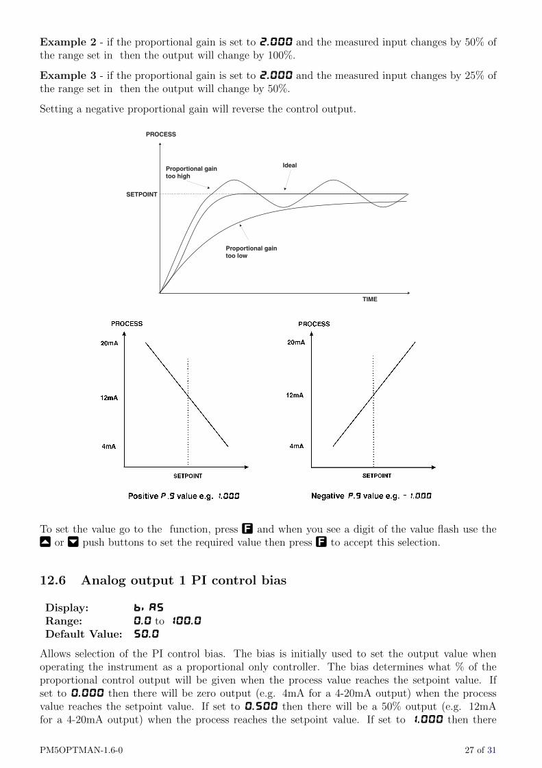
Example 2 - if the proportional gain is set to 2.000 and the measured input changes by 50% ofthe range set in then the output will change by 100%.
Example 3 - if the proportional gain is set to 2.000 and the measured input changes by 25% ofthe range set in then the output will change by 50%.
Setting a negative proportional gain will reverse the control output.
Proportional gaintoo high
Proportional gaintoo low
Ideal
SETPOINT
PROCESS
TIME
To set the value go to the function, press F and when you see a digit of the value flash use the^ or v push buttons to set the required value then press F to accept this selection.
12.6 Analog output 1 PI control bias
Display: biASRange: 0.0 to 100.0Default Value: 50.0
Allows selection of the PI control bias. The bias is initially used to set the output value whenoperating the instrument as a proportional only controller. The bias determines what % of theproportional control output will be given when the process value reaches the setpoint value. Ifset to 0.000 then there will be zero output (e.g. 4mA for a 4-20mA output) when the processvalue reaches the setpoint value. If set to 0.500 then there will be a 50% output (e.g. 12mAfor a 4-20mA output) when the process reaches the setpoint value. If set to 1.000 then there
PM5OPTMAN-1.6-0 27 of 31

will be a 100% output (e.g. 20mA for a 4-20mA output) when the process reaches the setpointvalue. If using proportional only control then when stable control is established there may be adifference between the process and the setpoint values. By altering the bias value the differencemay be minimised.
To set the value go to the function, press F and when you see a digit of the value flash use the^ or v push buttons to set the required value then press F to accept this selection.
This table shows the effect of the output current of changing proportional gain
and offset with the following settings: = 2.00, = 0.000
Effect on analog output (4-20mA used in this example)
7.00 1.000 0.000 Reading of 5.00 or below - 20mA output
Reading of 5.00 to 7.00 - mA output decreasing as reading ap-proaches 9.00
Reading 7.00 or above - 4mA output
7.00 1.000 1.000 Reading of 7.00 or below - 20mA output
Reading of 7.00 to 9.00 - mA output decreasing as reading ap-proaches 9.00
Reading 9.00 or above - 4mA output
7.00 1.000 0.500 Reading of 6.00 or below - 20mA output
Reading of 6.00 to 8.00 - mA output decreasing as reading ap-proaches 8.00 with 12mA output at 7.00
Reading 8.00 or above - 4mA output
7.00 0.500 0.500 Reading 5.00 or below - 20mA output
Reading 5.00 to 9.00 - mA output decreasing as reading approaches9.00 with 12mA output at 7.00
Reading 9.00 or above - 4mA output
7.00 -1.000 0.500 Reading of 6.00 or below - 4mA output
Reading of 6.00 to 8.00 - mA output increasing as reading ap-proaches 8.00 with 12mA output at 7.00
Reading 8.00 or above - 20mA output
12.7 Integral control output
The integral control output can be found from:
Integral control output =Error × I.G × time(secs)
60+ previous integral control output
Where I.G is the integral gain is set by the function.
28 of 31 PM5OPTMAN-1.6-0

12.8 Analog output 1 PI control integral gain
Display: I.gRange: -32.768 to 32.767Default Value: 0.000
Allows selection of the PI control integral gain. The integral control action will attempt to correctany offset which the proportional control action is unable to correct (e.g. errors due to a changingload). When the integral gain is correctly adjusted the control output is ramped up or down tomaintain control by keeping the process variable at the same value as the control setpoint. Anintegral gain which is too large will cause a rapid response to any error but can also lead toovershooting and oscillation. An integral gain which is too small will slow the time taken to reachthe setpoint. The optimum value chosen will depend on the lag time of the process and othercontrol settings. Start with a low figure and increase until a satisfactory response time is reached.
The integral gain figure has units of gain/minute. Setting a negative integral gain will reverse theintegral control action. If introduction of an integral gain figure causes the error to increase i.e.the process value is moving further away from the setpoint then check the sign of the integral gaine.g. if it is negative change it to a positive value.
Note that the sign of the integral gain value should be the same as the proportional gain value i.e.they should either both be positive or both be negative.
Integral gaintoo high
Ideal
SETPOINT
PROCESS
TIME
To set the value go to the function, press F and when you see a digit of the value flash use the^ or v push buttons to set the required value then press F to accept this selection.
12.9 Analog output 1 PI control integral high limit
Display: I.HRange: 0.0 to 100.0Default Value: 1.000
Allows selection of the PI control integral high limit.
The high limit sets the maximum control output for the integral term i.e. puts a high level limitto the integral control current or voltage output. The limit is used to reduce available outputswing and hence limit the effect of integral control output build up which can cause overshoot andinstability in the system. If the process value is not close to the setpoint value then the integral
PM5OPTMAN-1.6-0 29 of 31

control will see a large error. Since integral control output increases with time, the longer an erroris seen the more the integral control output will build up. Unless the output is limited then oncethe process reaches the setpoint the integral control output can be very large (e.g. 100%) causingthe process value to overshoot the control setpoint. A setting which is too high will result inallowing the integral control output to cause overshooting. A setting which is too low will resultin the integral control output being limited to an extent which means that the setpoint cannot bereached. Start with a low figure e.g. 10.0 and increase the value until a satisfactory response isreached. Maximum setting is 100.0 (100%). Having separate high and low limits is particularlyuseful if the process response is very one directional. For example in temperature control a heatermay be used to give a fast response in heating a tank of liquid when the temperature falls belowthe setpoint. The heat of the liquid rises quickly but any overshoot will mean that the temperatureis too high. The heater will be switched off but the tank of liquid will take a long time to cool tothe setpoint level.
To set the value go to the function, press F and when you see a digit of the value flash use the^ or v push buttons to set the required value then press F to accept this selection.
12.10 Analog output 1 PI control integral low limit
Display: I.LRange: 0.0 to 100.0Default Value: 1.000
Allows selection of the PI control integral low limit.
This function sets the minimum control output for the integral term value and works in the samemanner as described above except that the setting controls the low swing.
To set the value go to the function, press F and when you see a digit of the value flash use the^ or v push buttons to set the required value then press F to accept this selection.
12.11 Setting up the PI analog controller
1. Set the function to YES.
2. Set the control setpoint to the required setting.
3. Set the proportional control span as required.
4. Set the proportional gain to an arbitrary value e.g. 1.000.
5. Set the bias to 0.0 (0%).
6. Set the integral gain to 0.000 (i.e. off).
7. Set the integral high and low limits to an arbitrary value e.g. 20.00.
Initialise the control system and monitor the control results. If the original settings causes processoscillations then gradually decrease the proportional gain until the oscillations decrease to anacceptable steady cycle. If the original settings do not cause process oscillations then graduallyincrease the proportional gain until a steady process cycling is observed. Once the steady state isachieved note the difference between the display value and the control setpoint value. Gradually
30 of 31 PM5OPTMAN-1.6-0

increase or decrease the proportional offset value until the displayed value matches the controlsetpoint value.
If process load changes occur then the proportional offset value may no longer be valid for offsetfree control. By introducing the integral action, setpoint offset caused by the process load changeswill be minimised. Gradually increase the integral gain until the process begins to oscillate. Thenreduce the integral gain slightly to regain the control with minimum oscillation. Alter the high andlow integral limits to give the best regulation with minimum oscillation. Create a step change tothe process conditions and observe the control results. It may be necessary to fine tune the settingsto obtain optimum results. The table below summarises the effect of the main function settings.
Setup functions Symptom Solution
Proportional gain Slow response Increase proportional gain
High overshoot or oscillation Decrease proportional gain
Bias Process continually either above orbelow setpoint
Increase or decrease bias to compen-sate
Integral gain Slow response Increase integral gain
Instabillity or oscillation Decrease integral gain
PM5OPTMAN-1.6-0 31 of 31