pm605fe serie - itoh-denki.com · pm605fe serie. t. echncal docmen taton. 4. o - t14. the motorized...
TRANSCRIPT

PM605FE sEriETechnical documenTaTion

2PM605FE SERIE Technical documenTaTion Original notice - T1.4
1 - Presentation of the PowerMoller® product range Page 3 2 - Presentation of the series Page 4 General characteristics Structure and description Applications Characteristics depending on circuit board 3 - Transfer capacity Page 9 Ribbed belt drive4 - Presentation of the different fixing options Page 11 5 - Dimensional characteristics Page 13 Roller with pulley for ribbed belt - Hexagonal shaft with spring on free end Roller with pulley for ribbed belt- M8 threaded shaft with screw on free end Roller without drive - Hexagonal shaft with spring on free end Roller without drive - M8 threaded shaft with screw on free end6 - Dimensional characteristics - miscellaneous Page 17 Coated in natural rubber, nitrile rubber and polyurethane Crowned machining7 - Mounting on the frames Page 18 Mounting plate for plain 11.1 mm hexagonal shaft - Flat on top Mounting plate for plain 11.1 mm hexagonal shaft - Angle on top Mounting plate for threaded hexagonal shaft - Flat on top Mounting plate for threaded hexagonal shaft - Angle on top M8 threaded fixed shaft8 - Wiring Page 20 With CBM-105 circuit board With HB510 circuit board9 - Accessories Page 21 Ribbed belts Extension cables 24 VDC power supply 24 VDC distribution connector 10 - Product identification Page 23 Round label Square label Annex 1 : Incorporation declaration Page 24
Summary

3PM605FE SERIE Technical documenTaTion Original notice - T1.4
Electronic Motorized rollers Module
Standard circuit board
ZPA circuit board
HB510 HB510B
Externalcircuit board
Integratedcircuit board
Corresponding circuit board
Max load to be conveyed
Mechanical brake version
Module circuit board
HBR-605
90° transfer
F-RAT-S250
POP-UP CBM-105CBR-306
HBK-608
45° transfer
DC Brushless
Ø50
PM500 XE
Ø60,5
PM605 XE
B&W AS-i 3.0WenglorMolex
B&W AS-i 3.0WenglorMolex
PM500 XK
PM500 XC
PEPPERL-FUCHSAS-Interface
Molex
PEPPERL-FUCHSAS-Interface
Molex
Ø32
Ø50
Ø60,5
PM320 HS CB018
PM500 FECBM-105
HB510IB-E
PM500 FE-B CB016BHB510B
PM605 FE
PM605 FE-B CB016BHB510B
PM605 KT CB030HBK-608
CBM-105HB510
IB-E
HBR-605CBM-105CBR-306
Network controller
IB-E
IB-P
PM500 VE CBV-108 IB-P
PM605 VE CBV-108IB-P
PM500 XPB&W AS-i 3.0
WenglorMolex
PM605 XPB&W AS-i 3.0
WenglorMolex
Compatible module / sensor
CBR-306
CB018
CB016 CB016B
CB030
CBM-105
CBV-108
F-RAT-S300HBR-605CBM-105CBR-306
F-RAT-U225HBR-605CBM-105CBR-306
1 - PreSenTaTion of The Power moller® ProducT range

4PM605FE SERIE Technical documenTaTion Original notice - T1.4
The motorized roller PM605FE with brushless technology 24VDC, used with circuit board CBM-105 or HB510 is designed for conveying light and medium loads (up to 500kg) or order preparation, distribution, and for assembly lines. This circuit board is separated from the gear-motor in order to optimize the performance, durability of the roller and to offer diverse functions such as pulse signals, acceleration/deceleration, optional position holder... The assembly can be controlled by PLC.
ELEC
TRO
MEC
AN
ICA
L
Direct current and brushless 24 VDC 24 VDC (+ /- 10 %) – ripple ratio < 10 %
Isolation class E
Operation at 40°C
Continuous 100%
Intermittent1800 starts / hour maxi Minimum duty cycle = 1 s ON / 1 s OFFED = ON / (ON+OFF) ≤ 50 %
Brake Dynamic brakingProtection index IP54 (IP65 or cold room, contact us)Cable length 300 mm with JST connector - 9 pins
Protection Thermal protection (>95°C for circuit board, >110°C for motor)Protection against induced voltage
Environment 0/+40 °C - no condensation - or corrosive or explosive atmosphere - Vibrations < 0,5 G
Sound level ≈ 52 dB nominal 1 metre awaySpeed code 15 25 55Reduction ratio 1/44,90 1/26,67 1/12,64Connector Male 9-pin JST#S9B-XH-A
CONT
ROL
Circuit board functions See the characteristics of CBM-105 (page 7) and HB510 (page 8)
2 - PreSenTaTion of The SerieS
General characteristics
The PM605FE motorized roller is designed exclusively for indoor use.
5PM605FE SERIE Technical documenTaTion Original notice - T1.4
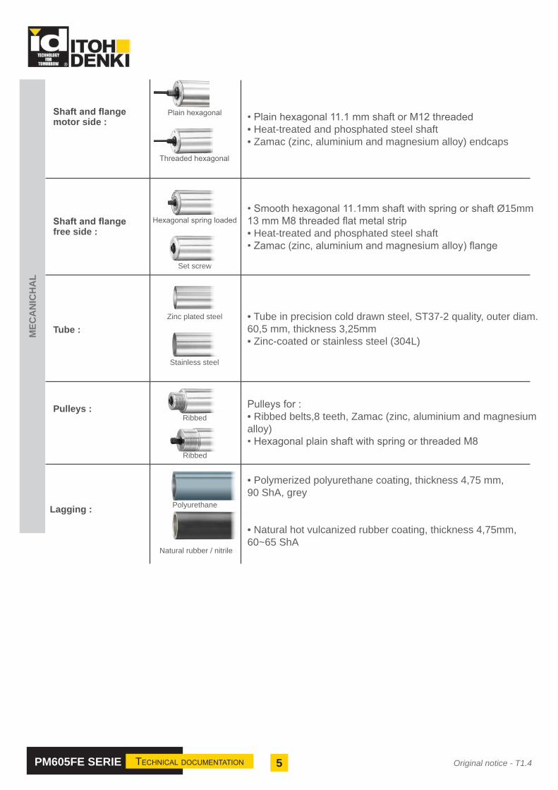
Shaft and flange motor side :
Set screw
Shaft and flange free side :
Tube :
Ribbed Pulleys :
Lagging :
Threaded hexagonal
Plain hexagonal • Plain hexagonal 11.1 mm shaft or M12 threaded• Heat-treated and phosphated steel shaft • Zamac (zinc, aluminium and magnesium alloy) endcaps
• Smooth hexagonal 11.1mm shaft with spring or shaft Ø15mm13 mm M8 threaded flat metal strip• Heat-treated and phosphated steel shaft • Zamac (zinc, aluminium and magnesium alloy) flange
Stainless steel
Polyurethane
Natural rubber / nitrile
• Polymerized polyurethane coating, thickness 4,75 mm, 90 ShA, grey
• Natural hot vulcanized rubber coating, thickness 4,75mm, 60~65 ShA
MEC
AN
ICH
AL
• Tube in precision cold drawn steel, ST37-2 quality, outer diam. 60,5 mm, thickness 3,25mm• Zinc-coated or stainless steel (304L)
Zinc plated steel
Hexagonal spring loaded
Ribbed
Pulleys for :• Ribbed belts,8 teeth, Zamac (zinc, aluminium and magnesium alloy)• Hexagonal plain shaft with spring or threaded M8

6PM605FE SERIE Technical documenTaTion Original notice - T1.4
Structure and description
Applications
STOPSTOP
ON OFF
STOP
Shaft at free end
TubeNoise and
shock aborber Endcaps with double bearing at motor end
Shaft at motor end
Power cable
Hall effect sensor
MotorNoise and
shock aborber
Planetary gear unitDrive wheelShield with double
bearing at free end
Zero pressure accumulation (ZPA)
90° transfer Cold roomLength measurement
Gate Floor conveyor Acceleration / Deceleration Stopping distance controlled by pulsed
signal (CBM-105)

7PM605FE SERIE Technical documenTaTion Original notice - T1.4
Characteristics depending on circuit board
characTeriSTicS SPeed code 15 SPeed code 25 SPeed code 55
el
ec
Tr
om
ec
ha
nic
Motor Direct current and brushless 24 VDC
Absorbed power (W)nominal 25 - 67,2
start-up 96
Tangential force (N)nominal 110,7 - 118,9 64,5 - 71,1 35,4 - 38,0
start-up 289,1 225 92,4
Operation Continuous or intermittent 1800 starts/h max. Minimum duty cycle : 1s ON / 1s OFF
Brake Dynamic braking
Speed (m/min)no load 2,7 - 21,3 4,5 - 35,5 9,3 - 74,7
nominal 2,7 - 16,1 4,5 - 30,7 9,3 - 57,2
Protection index (motorized roller) IP54, 65 (Contact us for other classes)
Length 290 to 1500 mm 270 to 1500 mm 270 to 1500 mm
Static load max. 300 - 1200 mm = 160 - 80 kg per roller
co
nT
ro
l
Input signal Start / Stop, Direction of rotation
Selection of rotation direction By dip switch (CW/CCW) or input signal
Speed setting20 speeds with a rotating switch
20 speeds by external analog voltage of 0-10VDC
Acceleration / Deceleration Adjustable with potentiometer from 0 to 2,5s
Servo-brake activation ON/OFF by dip switch
Pulse signal output (imp./tour) 89,9 53,34 25,28
Error signal out-put Over-heating, wiring error, under-voltage, over-voltage...
Protection Against polarity reversal 0/24V and power backfeed, fuse, integrated thermal protection
wiTh cBm-105
For other specifications, please contact us.

8PM605FE SERIE Technical documenTaTion Original notice - T1.4
wiTh hB510characTeriSTicS SPeed code 15 SPeed code 25 SPeed code 55
el
ec
Tr
om
ec
ha
nic
Motor Direct current and brushless 24 VDC
Absorbed power (W)nominal 29,3 - 60 28,8 - 61,9 29,3 - 60
start-up 96
Tangential force (N)nominal 98,0 - 105,0 56,0 - 62,0 31,3 - 33,6
start-up 289,1 186,4 92,4
Operation Continuous or intermittent 1800 starts/h max. Minimum duty cycle : 1s ON / 1s OF
Brake Dynamic braking
Nominal speed (m/min)no load 5,2 - 21,1 8,8 - 35,5 18,6 - 74,7
nominal 5,2 - 16,8 8,8 - 31,8 18,6 - 59,8
Protection index (motor roller) IP54, 65, cold room (Contact us for other classes)
Length 290 to 1500 mm 270 to 1500 mm 270 to 1500 mm
Static load max. 300 - 1200 mm = 160 - 80 kg per roller
co
nT
ro
l
Speed setting10 speeds with a rotating switch
10 speeds by external analog voltage of 0-10VDC
Error signal in-put Over-heating, wiring error, under-voltage, over-voltage...
Sensor output signal Recovery sensor state for PLC
Protection Against polarity reversal 0/24V and power backfeed, fuse, integrated thermal protection
Sensor timer Timing sequence of the motorized roller depending on the sensor status of the downstream zone
Run holding timer Timing sequence of the motorized roller depending on the sensor status of the zone to be left
Jam timer Jam/blockage detection of the load depending on the sensor status time
Emergency stop Stop of the motorized rollers of all the defined zones
Transfer mode Selection of train mode or singulation mode by dip switch
Transfer direction and logic Invert the direction of travel and logic for all the defined zones
Synchronization function Synchronization of several motorized rollers in the same zone
Forced Start / Forced Stop The forced start enables evacuating the load of the last zoneThe forced stop enables inserting load in a defined location
Speed control block area Speed variation simultaneous and synchronized of several motorized rollers
Modification program Contact us

9PM605FE SERIE Technical documenTaTion Original notice - T1.4
3 - TranSfer caPaciTy
Driven by ribbed belts
wiTh cBm-105
PM605FE 15m/min PM605FE 25m/min
• Load to transport
0 25 50 75 1000
100
200
300
400
500
600
700
800
Facteur de marche (%)
Poid
s de
la c
harg
e (K
g)
PM500FE 15m/min avec CBM-105 entrainant 9 rouleaux libres par courroie Poly V
PlastiqueU=0.03
CartonU=0.06
Plastic box (µ = 0,03)Cardboard box (µ = 0,06)
• 9 slave rollers driven by 1 motorized roller
These curves are given as a guide. Transfer capacity depends on the nature and quality of the transported load, the belt tension, the quality of the bearings, the nature of the sleeves, the ambient temperature...
0 25 50 75 1000
100
200
300
400
500
600
Facteur de marche (%)
Poid
s de
la c
harg
e (K
g)
PM605FE 15m/min avec CBM-105 entrainant 9 rouleaux libres par courroie Poly V
PlastiqueU=0.03
CartonU=0.06
0 25 50 75 1000
50
100
150
200
250
300
350
Facteur de marche (%)
Poid
s de
la c
harg
e (K
g)
PM605FE 25m/min avec CBM-105 entrainant 9 rouleaux libres par courroie Poly V
PlastiqueU=0.03
CartonU=0.06
0 25 50 75 1000
20
40
60
80
100
120
140
160
180
Facteur de marche (%)
Poid
s de
la c
harg
e (K
g)
PM605FE 55m/min avec CBM-105 entrainant 9 rouleaux libres par courroie Poly V
PlastiqueU=0.03
CartonU=0.06
PM605FE 55m/min
Load
wei
ght (
kg)
Duty cycle (%)
Load
wei
ght (
kg)
Duty cycle (%)
Load
wei
ght (
kg)
Duty cycle (%)

10PM605FE SERIE Technical documenTaTion Original notice - T1.4
wiTh hB510
PM605FE 15m/min PM605FE 25m/min
PM605FE 55m/min
0 25 50 75 1000
50100150200250300350400450500
Facteur de marche (%)
Poid
s de
la c
harg
e (K
g)
PM605FE 15m/min avec HB510 entrainant 9 rouleaux libres par courroie Poly V
PlastiqueU=0.03
CartonU=0.06
0 25 50 75 1000
50
100
150
200
250
300
Facteur de marche (%)
Poid
s de
la c
harg
e (K
g)
PM605FE 25m/min avec HB510 entrainant 9 rouleaux libres par courroie Poly V
PlastiqueU=0.03
CartonU=0.06
0 25 50 75 1000
20
40
60
80
100
120
140
160
Facteur de marche (%)
Poid
s de
la c
harg
e (K
g)
PM605FE 55m/min avec HB510 entrainant 9 rouleaux libres par courroie Poly V
PlastiqueU=0.03
CartonU=0.06
Load
wei
ght (
kg)
Duty cycle (%)
Load
wei
ght (
kg)
Duty cycle (%)
Load
wei
ght (
kg)
Duty cycle (%)
• Load to transport
0 25 50 75 1000
100
200
300
400
500
600
700
800
Facteur de marche (%)
Poid
s de
la c
harg
e (K
g)
PM500FE 15m/min avec CBM-105 entrainant 9 rouleaux libres par courroie Poly V
PlastiqueU=0.03
CartonU=0.06
Plastic box (µ = 0,03)Cardboard box (µ = 0,06)
• 9 slave rollers driven by 1 motorized roller
These curves are given as a guide. Transfer capacity depends on the nature and quality of the transported load, the belt tension, the quality of the bearings, the nature of the sleeves, the ambient temperature...
11PM605FE SERIE Technical documenTaTion Original notice - T1.4
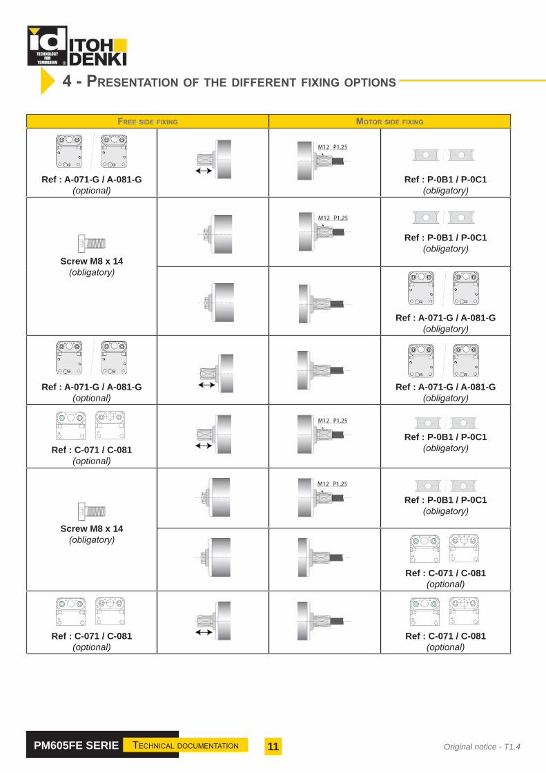
4 - PreSenTaTion of The differenT fixing oPTionS
free Side fixing moTor Side fixing
Ref : A-071-G / A-081-G(optional)
Ref : P-0B1 / P-0C1(obligatory)
Screw M8 x 14(obligatory)
Ref : P-0B1 / P-0C1(obligatory)
Ref : A-071-G / A-081-G(obligatory)
Ref : A-071-G / A-081-G(optional)
Ref : A-071-G / A-081-G(obligatory)
Ref : C-071 / C-081
(optional)
Ref : P-0B1 / P-0C1(obligatory)
Screw M8 x 14(obligatory)
Ref : P-0B1 / P-0C1(obligatory)
Ref : C-071 / C-081
(optional)
Ref : C-071 / C-081
(optional)
Ref : C-071 / C-081
(optional)

12PM605FE SERIE Technical documenTaTion Original notice - T1.4
2 nuts M5 2 cruciform bolt M5x15
2 spring washer M5
2 nuts M5 2 cruciform bolt M5x15
2 spring washer M5
Ref. C-071 Ref. C-081
2 spring washer M5
2 spring washer M5 2 cruciform bolt M5x15
2 nuts M5
2 nuts M5 2 cruciform bolt M5x15
Note : Nut ref. FEY02 should be used with the claw plate ref. P-0B1 or P-0C1.
P-0B1 + FEY02P-0C1 + FEY02
Ref. FEY0221,50
GRADE
SCALE :5:1 A3FEY02
MODIFY
Product
Itoh Denki Europe SAS Folio 1 / 1
APPROVEDCREATEDOn 26/06/18 by :DCOn 00/00/00 by :On 18/06/18 by : C.J
Format
MatterA A
B B
C C
D D
E E
F F
8 7 6 5 4 3 2 1
1
18,80
8,60

13PM605FE SERIE Technical documenTaTion Original notice - T1.4
PM605FE - Hexagonal threaded shaft motor side and hexagonal shaft with spring on free end
Dimensions PM605FE
Speed codeDimension (B) Tube length (L)
mini ≤ L ≤ maxmini ≤ B ≤ max15 339 ≤ B ≤ 1539 300 ≤ L ≤ 1500
25 / 55 319 ≤ B ≤ 1539 280 ≤ L ≤ 1500
Tube length 300 400 500 600 700 800 900 1000 1100 1200 1300 1400 1500
Weight (Kg)
15 m/min 3,8 3,9 4,3 4,7 5,1 5,5 5,9 6,3 6,7 7,1 7,8 8,2 8,625 m/min 3,6 3,7 4,1 4,5 4,9 5,3 5,7 6,1 6,5 6,9 7,6 8,0 8,455 m/min 3,6 3,7 4,1 4,5 4,9 5,3 5,7 6,1 6,5 6,9 7,6 8,0 8,4
Static load max (kg) 160 160 130 130 100 100 80 80 70 70 50 40 40Axial force max (N) 490
Roller with pulley for ribbed belt - Hexagonal shaft with spring on free end
weighT / STaTic load / axial force
orRef. C-071Ref. C-081
5 - dimenSional characTeriSTicS
PM605FE - Hexagonal plain shaft motor side and hexagonal shaft with spring on free end
orRef. C-071Ref. C-081
orRef. C-071Ref. C-081

14PM605FE SERIE Technical documenTaTion Original notice - T1.4
PM605FE - Hexagonal threaded shaft motor side and M8 threaded shaft with screw on free end
Dimensions PM605FE
Speed codeDimension (B) Tube length (L)
mini ≤ L ≤ maxmini ≤ B ≤ max15 331 ≤ B ≤ 1541 290 ≤ L ≤ 1500
25 / 55 311 ≤ B ≤ 1541 270 ≤ L ≤ 1500
Roller with pulley for ribbed belt - M8 threaded shaft with screw on free end
weighT / STaTic load / axial force
Tube length 300 400 500 600 700 800 900 1000 1100 1200 1300 1400 1500
Weight (Kg)
15 m/min 3,7 4,1 4,5 4,9 5,3 5,7 6,1 6,5 6,9 7,3 7,7 8,1 8,525 m/min 3,5 3,9 4,3 4,7 5,1 5,5 5,9 6,3 6,7 7,1 7,5 7,9 8,355 m/min 3,5 3,9 4,3 4,7 5,1 5,5 5,9 6,3 6,7 7,1 7,5 7,9 8,3
Static load max (kg) 160 160 130 130 100 100 80 80 70 70 50 40 40Axial force max (N) 490
PM605FE - Hexagonal plain shaft motor side and M8 threaded shaft with screw on free end
orRef. C-071Ref. C-081

15PM605FE SERIE Technical documenTaTion Original notice - T1.4
PM605FE - Hexagonal threaded shaft motor side and hexagonal shaft with spring on free end
Dimensions PM605FE
Speed codeDimension (B) Tube length (L)
mini ≤ L ≤ maxmini ≤ B ≤ max15 313 ≤ B ≤ 1515 300 ≤ L ≤ 1500
25 / 55 293 ≤ B ≤ 1515 280 ≤ L ≤ 1500
Roller without drive - Hexagonal shaft with spring on free end
weighT / STaTic load / axial force
orRef. C-071Ref. C-081
Tube length 300 400 500 600 700 800 900 1000 1100 1200 1300 1400 1500
Weight (Kg)
15 m/min 3,5 3,9 4,3 4,7 5,1 5,5 5,9 6,3 6,7 7,1 7,5 7,9 8,325 m/min 3,3 3,7 4,1 4,5 4,9 5,3 5,7 6,1 6,5 6,9 7,3 7,7 8,155 m/min 3,3 3,7 4,1 4,5 4,9 5,3 5,7 6,1 6,5 6,9 7,3 7,7 8,1
Static load max (kg) 160 160 130 130 100 100 80 80 70 70 50 40 40Axial force max (N) 490
PM605FE - Hexagonal plain shaft motor side and hexagonal shaft with spring on free end
orRef. C-071Ref. C-081
orRef. C-071Ref. C-081

16PM605FE SERIE Technical documenTaTion Original notice - T1.4
PM605FE - Hexagonal threaded shaft motor side and M8 threaded shaft with screw on free end
Dimensions PM605FE
Speed codeDimension (B) Tube length (L)
mini ≤ L ≤ maxmini ≤ B ≤ max15 305 ≤ B ≤ 1515 290 ≤ L ≤ 1500
25 / 55 285 ≤ B ≤ 1515 270 ≤ L ≤ 1500
weighT / STaTic load / axial force
Roller without drive - M8 threaded shaft with screw on free end
Tube length 300 400 500 600 700 800 900 1000 1100 1200 1300 1400 1500
Weight (Kg)
15 m/min 3,5 4,2 4,6 5,0 5,4 5,8 6,2 6,6 7,0 7,4 7,5 7,9 8,325 m/min 3,3 4,0 4,4 4,8 5,2 5,6 6,0 6,4 6,8 7,2 7,3 7,7 8,155 m/min 3,3 4,0 4,4 4,8 5,2 5,6 6,0 6,4 6,8 7,2 7,3 7,7 8,1
Static load max (kg) 160 160 130 130 100 100 80 80 70 70 50 40 40Axial force max (N) 490
PM605FE - Hexagonal plain shaft motor side and M8 threaded shaft with screw on free end
orRef. C-071Ref. C-081
17PM605FE SERIE Technical documenTaTion Original notice - T1.4
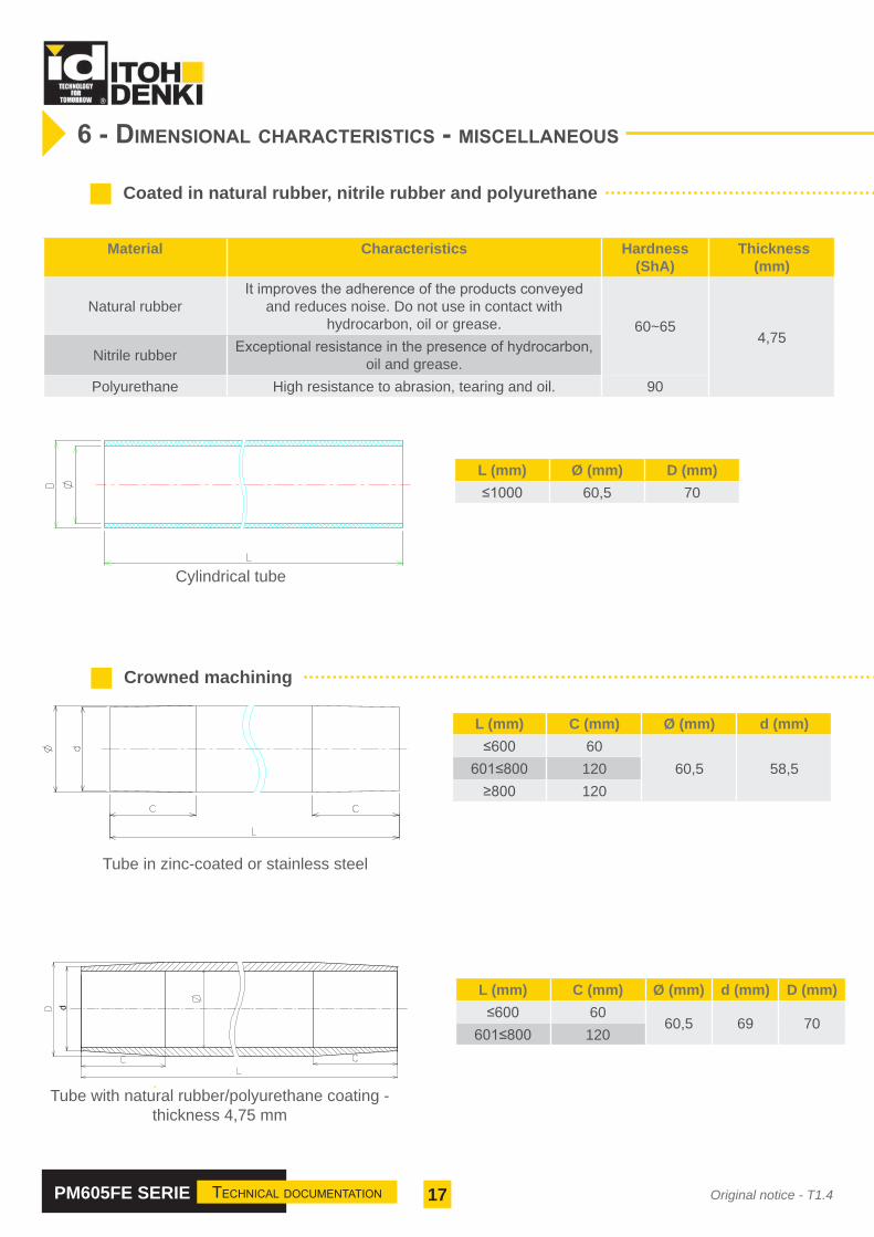
6 - dimenSional characTeriSTicS - miScellaneouS
Coated in natural rubber, nitrile rubber and polyurethane
Material Characteristics Hardness (ShA)
Thickness (mm)
Natural rubberIt improves the adherence of the products conveyed
and reduces noise. Do not use in contact with hydrocarbon, oil or grease. 60~65
4,75Nitrile rubber Exceptional resistance in the presence of hydrocarbon,
oil and grease.Polyurethane High resistance to abrasion, tearing and oil. 90
L (mm) Ø (mm) D (mm)≤1000 60,5 70
Cylindrical tube
Crowned machining
L (mm) C (mm) Ø (mm) d (mm) D (mm)≤600 60
60,5 69 70601≤800 120
Tube in zinc-coated or stainless steel
Tube with natural rubber/polyurethane coating - thickness 4,75 mm
dd
L (mm) C (mm) Ø (mm) d (mm)≤600 60
60,5 58,5601≤800 120≥800 120

18PM605FE SERIE Technical documenTaTion Original notice - T1.4
7 - mounTing on The frameS
Mounting plate for plain 11.1 mm hexagonal shaft - FLAT ON TOP
Mounting plate for plain 11.1 mm hexagonal shaft - ANGLE ON TOP
Conveyor with hole Ø12,1mm or hexagonal 11,2mm
Conveyor with hole Ø12,1mm or hexagonal 11,2mm
PlateReference A-071-G
PlateReference A-081-G
PlateReference C-081
PlateReference C-071

19PM605FE SERIE Technical documenTaTion Original notice - T1.4
Mounting plate for threaded hexagonal shaft - FLAT ON TOP
Mounting plate for threaded hexagonal shaft - ANGLE ON TOP
M8 threaded fixed shaft
Claw plate NutReference P-0B1 FEY-02
Claw plate NutReference P-0C1 FEY-02
BoltReference SP-M8-14
Conveyor with hole Ø12,1mm or hexagonal 11,2mm
Conveyor with hole Ø12,1mm or hexagonal 11,2mm
Conveyor with holes ø8,4mm
POWER MOLLER 24 ® DC
19
Accessoires pour axe hexagonal � leté
Plaque à griffe P-0B1Convoyeur avec perçage � 12,1 mm.
33
4049
Ø12.8
10 221.
5
3
11.1
Plaque à griffe P-0C1Convoyeur avec perçage � 12,1 mm.
33
4049
Ø12
.8
10 221.
5
311.1
Rondelle éventailConvoyeur avec découpe hexagonale.
18,75
21,5
6,82
ou
ou
21,50
18,8
0
8,60
21,50
18,8
0
8,60

20PM605FE SERIE Technical documenTaTion Original notice - T1.4
8 - wiring
With CBM-105 circuit board
With HB510 circuit board
The circuit board controls and protects the brushless motorized roller.
The circuit board controls the motorized roller and manages the zones to ensure ZPA (zero pressure accumulation)
Towards another HB510 motor control
Towards another HB510 circuit board

21PM605FE SERIE Technical documenTaTion Original notice - T1.4
9 - acceSSorieS
Ribbed belt
Pitch Pitch
Pitch between the rollers
(mm)For pulley Ø43mm
Number of teeth
2 3 4
60-63 Ref. 2PJ256-43 Ref. 3PJ256-43 Ref. 4PJ256-4364-65 Ref. 2PJ265-43 Ref. 3PJ265-43 Ref. 4PJ265-4366-67 Ref. 2PJ270-43 Ref. 3PJ270-43 Ref. 4PJ270-4371-72 Ref. 2PJ282-43 Ref. 3PJ282-43 Ref. 4PJ282-4373-75 Ref. 2PJ286-43 Ref. 3PJ286-43 Ref. 4PJ286-4376-78 Ref. 2PJ290-43 Ref. 3PJ290-43 Ref. 4PJ290-4380-84 Ref. 2PJ302-43 Ref. 3PJ302-43 Ref. 4PJ302-4387-91 Ref. 2PJ314-43 Ref. 3PJ314-43 Ref. 4PJ314-4392-95 Ref. 2PJ316-43 Ref. 3PJ316-43 Ref. 4PJ316-4397-101 Ref. 2PJ336-43 Ref. 3PJ336-43 Ref. 4PJ336-43103-107 Ref. 2PJ346-43 Ref. 3PJ346-43 Ref. 4PJ346-43115-118 Ref. 2PJ372-43 Ref. 3PJ372-43 Ref. 4PJ372-43119-121 Ref. 2PJ376-43 Ref. 3PJ376-43 Ref. 4PJ376-43123-128 Ref. 2PJ388-43 Ref. 3PJ388-43 Ref. 4PJ388-43129-134 Ref. 2PJ416-43 Ref. 3PJ416-43 Ref. 4PJ416-43142-147 Ref. 2PJ436-43 Ref. 3PJ436-43 Ref. 4PJ436-43150-156 Ref. 2PJ442-43 Ref. 3PJ442-43 Ref. 4PJ442-43157-161 Ref. 2PJ456-43 Ref. 3PJ456-43 Ref. 4PJ456-43170-176 Ref. 2PJ486-43 Ref. 3PJ486-43 Ref. 4PJ486-43196-202 Ref. 2PJ536-43 Ref. 3PJ536-43 Ref. 4PJ536-43208-215 Ref. 2PJ570-43 Ref. 3PJ570-43 Ref. 4PJ570-43254-258 Ref. 2PJ636-43 Ref. 3PJ636-43 Ref. 4PJ636-43305-310 Ref. 2PJ746-43 Ref. 3PJ746-43 Ref. 4PJ746-43

22PM605FE SERIE Technical documenTaTion Original notice - T1.4
For PM605FE and CBM-105 / HB510 - Male / Female - 9 pins
Length Part number of the extension cable
1200mm ACE-CBM-B12002700mm ACE-CBM-B2700
Extension cables
24 VDC power supply
Reference Input Output Power Start-up boostCT-10-241
380~480V3 ph
24V-10A 240W 120%QT-20-241 24V-20A 480W 150%QT-40-241 24V-40A 960W 150%
Available only for DC Power Mollers that require extra cable length
Cables available in the following standard lengths:- 600mm (23.62"), 1200mm (47.24"), and 2700mm (106.30") Notes
Allows for easy hook up between Power Moller roller cable and driver card - Maximum distance from Available in the following configurations: roller to card - 3000mm
- 9 pin male to 9 pin female -Ambient Temperature- 9 pin male to 10 pin female -22~140º F (-30~60ºC)- 10 pin male to 10 pin female- 12 pin male to 12 pin female
Example Model Numbers:— — —
— — —
Maleof Pins
Extension Number
Female
M-F
Molded Extension Cables
M-F EXT 9 PIN 600
EXT 9 PIN/10 PIN
Extension
1200
CableNumber
Femaleof Pins Length
Cable
CableMale
Cable Length
37mm[1.46"]
30m
m[1
.18"
]
10mm[0.39"]
37mm[1.46"]
10 Pin Female
9 Pin Female
60mm[2.36"]
60mm[2.36"]
Length
Length
10mm[0.39"]
37.5
mm
[1.4
8"]
37mm[1.46"]
Length
12 Pin Female
60mm[2.36"]
12 Pin Male
9 Pin Male
M-F-EXT-9 PIN-LENGTH (MM)
M-F-EXT-10 PIN-LENGTH (MM)
M-F-EXT-12 PIN-LENGTH (MM)
10mm[0.39"]
32.5
mm
[1.2
8"]
10 Pin Male
Itoh Denki USA, Inc135 Stewart RoadWilkes-Barre, PA 18706
www.itohdenki.comPhone 888-310-8811
Specifications subject to change without notice
- Very weak inrush current.- Accepts excess current of 120 to 150% at startup (according to model)
24 VDC distribution connector
� UK Branch� ITOH DENKI EUROPE S.A.S.� Zweigniederlassung Deutschland� Victoria Court - 91 Huddersfield Road� 490 Avenue des jourdies - Z.A.E. Les Jourdies� Neumeyerstraße 48� HOLMFIRTH HD9 3JA - UNITED KINGDOM� 74800 ST PIERRE EN FAUCIGNY - FRANCE� 90411 NÜRNBERG - DEUTCHLAND� tel: +44(0)1484 68 10 10 - Fax: +44(0)1484 68 08 08� B.P. 323 - 748807 ST PIERRE EN FAUCIGNY Cedex - FRANCE� Tél: +49(0)911 25 26 200 - Fax: +49(0)911 25 26 201� Web: www.itohdenki.co.uk - E-mail: [email protected]� Tél : +33(0)4 50 03 09 99 - Fax : +33(0)4 50 03 07 60� Web: www.itoh-denki.de - E-mail: [email protected]� Registered N.: FC027589 - Registered in England and Wales� Web : www.itoh-denki.com - E-mail : [email protected]� Handelsregisternummer: HRB25221
�S.A.S. au capital de 460 000 Euros - SIRET 343 034 344 000 30 - Code APE 4669B - R.C.S. BONNEVILLE 87 B413 - N. TVA : FR 71 343034344
Schematic DiagramPower distribution connector
Sub-cable to next zoneTypical size: 1.5 - 4.00mm
1 x Ø 3.5 for M3 screw & nut or aNo 6 self tapping screw from below2 x Ø 2.8 for locating pips
Cable to cirbuit boardTypical size: 1.0 - 1.5mm
WAGO 734 series 2-pole
Ref: 734-102 suppliedwith circuit board
35
11
24
PD-2P Power distribution connector
- 32A max current rating- two poles- 4 ways per pole- 0.5 - 4.00mm cable- fixing by M3 bolt or screw
Main 24v power cableTypical size: 1.5 - 4.00mm
HB510 or CB016 circuit board
NB remove 11mm of cable insulation to ensure retention inside the connector.
�Circuit diagram��
Mounting holes�
24v
0vspare
spare
circuit board
ZLP zone
Ref: PD-2PPower distribution connector blockTwo pole, 4-way connections (0.5 - 4.00mm2)
Zone sub-feed cable24v Main feed
HB510Comms
cable
Circuit Board
21
35 24
Ø 3.5
Ø 2.8
Ø 2.8
9
9
- 32A max- 2 poles with markings«24V / OV»- 4 connectors per pole- Cable 0.5 - 4.00mm (AWG........)- Fixed with M3 bolt or screw
ConnectorReference PD-2P
Circuit board
Zone power cable
Power cable between zones
Ref. PD-2PDistribution
connector 24VDC
Mains power supply 24VDC

23PM605FE SERIE Technical documenTaTion Original notice - T1.4
10 - ProducT idenTificaTion
ITO
H D
EN
KI P
M
605FE0550800X00SC001 10/14 1151 IP54 24VDC 55m/mn S1
1
2
3
4
56
7
1
2
3
4
5
6
7
10/14PM605FE0550800X00SC001
1
2
3
4
5
6
7
8
7
Power Moller® rollers come with a round label affixed to the endcaps at the motor end.The following information are shown on the label :
Power Moller® rollers come with a square self-adhesive label that must be affixed to the conveyor,to facilitate any future maintenance. The following information are shown on the label :
PM605FE 055 0800 X 00SC0011
Product reference number
Month and year of manufacture
Serial number
Protection index
Power supply
Speed
Operation
Product reference number
Month and year of manufacture
Serial number
Protection index
Power supply
Nominal intensity
Absorbed power
Speed
Operation
SerieSpeed code
Tube length(L) Without brake
Specifications
Round label
Square label

24PM605FE SERIE Technical documenTaTion Original notice - T1.4
incorPoraTion declaraTionin accordance with the EC Machinery Directive 2006/42/EC, Annex II B
The manufacturer:
ITOH DENKI CO., Ltd1146-2 Asazuma-Cho, Kasai, Hyogo 679-0105 Japan
Distributed in Europe by :
ITOH DENKI Europe SAS490 avenue des Jourdies - PAE les Jourdies - BP 32374807 St Pierre en Faucigny Cedex - France
hereby declares that the product series :
Pm605fe moTorized roller
is an incomplete machine as defined in the EC Machinery Directive and therefore does not fully meet the requirements of this Directive. Commissioning is prohibited until the whole machine/system in which it is incorporated is declared to be in compliance with the EC Machinery Directive
The health and safety requirements of Annex I have been applied. The special technical documents in accordance with Annex VII have been drawn up (and, if appropriate, submitted to the competent authorities).
Person authorized to compile the technical documentation :
ITOH DENKI CO., LtdToshiyuki TACHIBANA1146-2 Asazuma-Cho, Kasai, Hyogo 679-0105 Japan
ITOH DENKI EUROPE SAS Damien CLERC 490 Avenue des Jourdies, 74800 St Pierre en Faucigny - France
EC Directives applied : • Machinery Directive 2006/42/EC • European EMC Directive 2014/30/EC • European RoHS Directive 2011/65/EU
ITOH DENKI EUROPE SAS, undertakes to forward, following a duly motivated request from the national authorities, the relevant information concerning the quasi-machine.
Saint Pierre en Faucigny, 15 December 2017 T. AKASHI, General Director
annex 1

ITOH DENKI EUROPE S.A.S.
490 Av. des JourdiesP.A.E. les Jourdies
74800 St Pierre en Faucigny - FranceTél. : +33 (0)4 50 03 09 99Fax : +33 (0)4 50 03 07 60
E-mail : [email protected]
WWW.ITOH-DENKI.COM
ITOH DENKI UKBRANCH OFFICE
Suite 1 Trinity Space CentreWaldorf Way
Wakefield WF2 8DH - UKTel : +44 (0)1924 366 539Fax : +33 (0)4 50 03 07 60
E-mail : [email protected]
ITOH DENKI GERMANYBRANCH OFFICE
Neumeyerstraße 4890411 NÜRNBERG - Deutschland
Tel : +49 911 25 26 - 200Fax : +49 911 25 26 - 201
E-mail : [email protected]