pma eco 11 - controlador de temperatura, processos ... · 2 eco11 miniregler overall dimensions (in...
TRANSCRIPT

GENERAL
Due to its extremely compact dimen-
sions, the ECO 11 can be installed
even in the smallest machines. Its uni-
versal input and up to three switching
outputs enable the controller to be
adapted perfectly to the most varied
automation tasks.
The unit is configurable as a signaller
or PID two-point controller with inver-
se (heating) or direct (cooling) charac-
teristic.
SAFE OPERATION
The unit is operated by means of just
3 front-panel keys that provide access
to the following levels:
– Operation (standard)
– Parameter adjustment
– Configuration
– Calibration
The extended Operating Level enables
both setpoints and the alarms to be
adjusted, provided that the level has
been enabled.
DISPLAYS
During normal operation, the large
4-digit LED display (red or green) ensu-
res easy reading of the process value.
In the Parameter Level, the display al-
ternates between the parameter name
and its value, whereby the scroll key is
used to call the different parameters
sequentially for adjustment.
In addition, 3 indicator LEDs show the
following operating conditions by me-
ans of On, Off, or Blinking:
Red LED (control deviation)
Process value < setpoint : Off
Process value = setpoint : On
Process value > setpoint : Blinking
Yellow LED (operating mode)
Normal operation : Off
Parameter Level selected : On
Configuration Level selected : Blinking
Red LED (alarm)
Blinks with an active alarm.
Fault display
Exceeded measuring range and sen-
sor fault are indicated.
Options
Optionally, either a serial RS 485 inter-
face (Modbus RTU) or an additional re-
lay (Alarm 2; Output 3) can be fitted.
UNIVERSAL INPUT
The input is configurable for all con-
ventional signal and sensor types.
With thermocouple or Pt 100 input,
the resolution can be selected with or
without decimals. Apart from °C, the
display can be changed to °F or to line-
ar engineering units.
Current and voltage inputs are scalable
in the range -1999...9999, with up to 3
decimals (999,9...9,999).
The setpoint limits are adjustable wit-
hin the measuring ranges.
In case of a sensor fault, the control
outputs are switched off (0% output).
Offset
For the purpose of measurement cor-
rection, a constant value can be added
to the measurement signal.
CONTROLLER FUNCTIONS
Either PID, PD, PI or P behaviour is
configurable.
Self-tuning function
The start-up tuning function (manual
advance tuning) determines the best
PID parameters by means of a 100%
step change of the output, either at
the push of a button (operating menu)
or automatically at power-up (EasyTu-
ne; manual adjustment of control para-
meters is disabled).
Setpoint
Apart from the main setpoint SP1, a
second setpoint SP2 can be adjusted
and selected from the front.
Operating sense
The operating sense for heating can
be switched from ‘inverse’ (Heating)
to ‘direct’ (Cooling).
CONFIGURABLE ALARM
OUTPUTS
Both alarm outputs work in the nor-
mally de-energized mode: Alarm relays
or logic signals are energized in case
of an alarm, and the corresponding red
LED blinks.
Alarm functions are configurable as
absolute or relative measurement va-
lue alarms (min. or max.) or bandwidth
alarm (symmetrical to setpoint).
ECO 11Mini controller & indicator
Indicator, signaller, or two-point controller
Output sense selectable direct/inverse
Accurate control behaviour with 250 ms scanning cycle
High-precision universal input
Auto/manual switchover w/W2 from front panel
Up to three switching outputs (control output & alarms)
Output function selectable as control or alarm
RS 485 with Modbus RTU protocol
Front panel protection mode IP 66
PMA
econom
ylin
e
INTERFACE (OPTION)
The following parameters can be
read/written via the digital RS 485 in-
terface (Modbus RTU):
Read: Alarm status, process value, ef-
fective setpoint, output value, control
deviation.
Write: Start of tuning function, limit valu-
es, setpoints, control parameters, deci-
mal point, measured value correction.
GALVANIC ISOLATION
The universal input is galvanically isola-
ted from the power supply. Output 1
(logic) is not isolated from the input.
TECHNICAL DATA
UNIVERSAL INPUT
Scanning cycle
250 ms
Digital input filter
0…100 s, adjustable in steps of 1 s.
Input resolution
Approx. 14 bits
Input resistance
mA DC: 47 kΩThermocouples, mV: >10 MΩ
MEASURING RANGES
Thermocouples
Types: see table
Characteristic
Temperature-linear
Sensor monitoring
Response time: 2 s
Controller outputs are switched off
(output value 0%).
Measurement error
0,1% of measuring range ± 1 digit
(Types J and T: 0,25 %)
Linearization
Error: < 0,2 °C (typically 0,05 °C)
Without decimals: < ±0,5 °C
Cold-junction compensation
< ±0,7 °C at reference conditions.
Resistance thermometer
Sensor: Pt 100
Measuring ranges
-128,8 … 537,7 °C (-199,9 … 999,9 °F)
-199 … 800 °C (-328 … 1472 °F)
Resolution: 0,1 K or 1 K
Characteristic: temperature-linear
Connecting principle: three-wire
Sensor current: approx. 150 µA
Sensor monitoring
Acts on sensor break and short circuit.
Controller outputs are switched off
(output value 0%), and Min alarm is
triggered.
Response time: 2 s
Measurement error
< ±0,1% of measuring range ± 1 digit.
Linearization error
< 0,2°C (typically 0,05 °C)
Without decimals: <±0,5 °C
Lead resistance effect
< 0,5% of measurement error with
50 Ω/lead
Current and voltage
Measuring ranges
0...20 mA, 4...20 mA,
0...50 mV, 10...50 mV,
Scaling: -1.999...9.999
Resolution: 1 digit
Characteristic: linear
Measurement error
0,1% of measuring range ± 1 digit
Break monitoring
Not with 0...20 mA!
Response time: 2 s
Controller outputs are switched off
(output value 0%).
Max alarm is triggered with mA input.
Min alarm is triggered with mV input.
Measurement error
0,1% of measuring range ± 1 digit.
2 ECO11 Miniregler
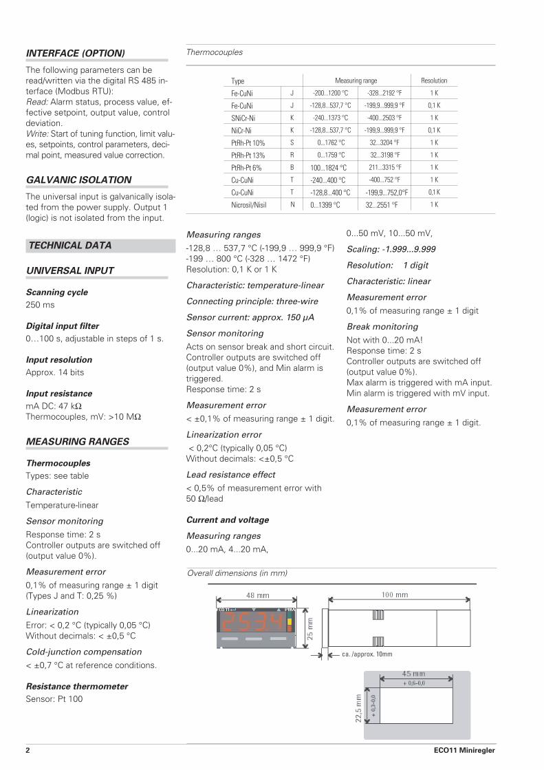
Overall dimensions (in mm)
Type Measuring range Resolution
Fe-CuNi J -200...1200 °C -328...2192 °F 1 K
Fe-CuNi J -128,8...537,7 °C -199,9...999,9 °F 0,1 K
SNiCr-Ni K -240...1373 °C -400...2503 °F 1 K
NiCr-Ni K -128,8...537,7 °C -199,9...999,9 °F 0,1 K
PtRh-Pt 10% S 0...1762 °C 32...3204 °F 1 K
PtRh-Pt 13% R 0...1759 °C 32...3198 °F 1 K
PtRh-Pt 6% B 100...1824 °C 211...3315 °F 1 K
Cu-CuNi T -240...400 °C -400...752 °F 1 K
Cu-CuNi T -128,8...400 °C -199,9...752,0°F 0,1 K
Nicrosil/Nisil N 0...1399 °C 32...2551 °F 1 K
Thermocouples

OUTPUTS
Types:
1 x relay / 1 x logic; optionally 1 addi-
tional relay (Output 3)
Relays
Contact type: potential-free, normally
open
Contact rating:
Max. 2 A / 150 VAC, resistive load,
Min. 100 mA, 5 V AC/DC:
Electrical service life: 500.000 swit-
ching cycles at max. contact rating.
• If the relays operate external
contactors, these must be fitted with
RC snubber circuits to prevent
excessive switch-off voltage peaks.
Logic output
Load: >10 V with 20 mA into >500 Ω load
POWER SUPPLY
AC voltage
Voltage: 90...264 VAC
Frequency: 50/60 Hz
Power consumption: 7,5 VA
Universal supply
Voltage: 12...24 VAC, 50/60 Hz and
12...30 VDC
Power consumption: 7,5 VA or 4 W
CONTROL BEHAVIOUR
Proportional band
Pb = 0,5...999,9 % of measuring range
Working point: 0...100 %
Integral action time:
1 s...99 min 59 s...OFF
Derivative action time:
0...99 min 59 s
Switching duty cycle
0,5 s (only logic output); 1, 2, 4, up to
512 s
Hysteresis (only signaller)
0,1...19 % of measuring range
Operating sense
Inverse (‘heating’) or direct (‘cooling’)
Output response on sensor break or
control loop error: controller outputs
switched off.
Setpoint functions
Second setpoint: selectable (switcho-
ver via control input)
Self-tuning function
Method: configurable
Manual preconfiguration
Pulse method during start-up with 100
% output signal. If the attempt is suc-
cessful, the PID parameters become
effective automatically.
Condition: (x-w) > 5% of measuring
range.
Automatic preconfiguration
Pulse method after power up.
Automatic self-tuning
Tuning attempt at setpoint (1 cycle)
Start condition: (x - w) > 0,15 % of
measuring range
Scanning cycle: 250 ms
ALARMS
See text for a description of the
functions. Quantity: 2 (min / max)
COMMUNICATION
Interface: RS 485
Protocol: Modbus RTU
Controller addresses: 1...255
Transmission speed: 1200...19.200 bits/s
Galvanic isolation: between inputs/out-
puts, and power supply
ENVIRONMENTAL CONDITIONS
Operating temperature: 0...55 °C
Relative humidity: 20...95 %, no con-
densation
Storage temperature: -20...+80 °C
Reference conditions
(for specified accuracy)
Ambient temperature: 20 °C ±2 °C
Humidity: 60...70 % rH
Supply voltage: 100...240 VAC, 50 Hz
± 1%
Source impedance (TC): < 10 ΩLead resistance (Pt 100): < 0,1 Ω
TESTS
Electrical safety
According to DIN EN 61 010-1
Over-voltage category II
Contamination degree 2
Working voltage range 240 VAC
Electromagnetic compatibility
According to EN 61 326
GENERAL
Housing
Front dimensions: 48 x 24 mm
(1/32 DIN)
Mounting depth: 100 mm
Front panel cutout: 45 x 22 mm
Protection mode
Front: IP 66
Electrical connections
Screw terminals for max. 1,5 mm²
Weight: approx. 120 g
ECO11 Miniregler 3
Connecting diagram

PMA
Prozess- und Maschinen- Automation GmbH
P.O. Box 31 02 29
D-34058 Kassel
Tel.: +49 - 561- 505 1307
Fax: +49 - 561- 505 1710
E-mail: [email protected]
Internet: http://www.pma-online.de
Your local representative:
Printed in Germany - Edition 04/2004a - Subject to alteration without notice - 9498 737 49213
PMA
Ordering code