pmc-24v600w1ba (december 2018, rev. 02)
TRANSCRIPT

TECHNICAL DATASHEET
PMC Panel Mount Power Supply
24V 600W 1 Phase / PMC-24V600W1BA
All parameters are specified at 25°C ambient and AC input unless otherwise indicated. www.DeltaPSU.com (December 2018, Rev. 02)
1
PMC Highlights & Features
Universal AC input range High PF > 0.99 @ 115Vac Power Boost of 200% for 5 seconds Meet Surge Immunity IEC 61000-4-5, Level 4
(CM: 4kV, DM: 2kV) Built-in fan speed control and fan lock protection Wide operating temperature range -20°C to 70°C Overvoltage / Overcurrent / Over Temperature / Short Circuit
Protections
Safety Standards
CB Certified for worldwide use
Model Number: PMC-24V600W1BA
Unit Weight: 1.60 kg
Dimensions (L x W x D): 215 x 120 x 61 mm
General Description
The PMC-24V600W1BA has a power rating of 600W with 24V output voltage. The product features Power Boost of 200% (up to 1200W) for 5 seconds and built-in fan speed control with fan lock protection. The PMC-24V600W1BA accepts the full universal AC input range and have been approved for major safety standards like IEC/EN/UL 60950-1 (ITE), EMI according to EN 55011 (Industrial, scientific and medical (ISM) radio-frequency equipment) and EMS according to EN 61000-6-2 (Immunity for industrial environments).
Model Information
PMC Panel Mount Power Supply
Model Number Input Voltage Range Output Voltage Output Current
PMC-24V600W1BA 85-264Vac (120-370Vdc) 24Vdc 25.0A
Model Numbering
PM C – 24V 600W 1 B A
Panel Mount Product Type C – Enclosed
Output Voltage Output Power Single Phase With PFC Front Face connector

TECHNICAL DATASHEET
PMC Panel Mount Power Supply
24V 600W 1 Phase / PMC-24V600W1BA
All parameters are specified at 25°C ambient and AC input unless otherwise indicated. www.DeltaPSU.com (December 2018, Rev. 02)
2
Specifications
Input Ratings / Characteristics
Nominal Input Voltage 100-240Vac
Input Voltage Range 85-264Vac (Refer to the Output De-rating VS. Input Voltage graph)
Nominal Input Frequency 50-60Hz
Input Frequency Range 47-63Hz
Nominal DC Input Voltage 142-340Vdc
DC Input Voltage Range* 120-370Vdc (Refer to the Output De-rating VS. Input Voltage graph)
Input Current < 6.50A @ 115Vac, < 3.20A @ 230Vac
Efficiency at 100% Load > 86.0% @ 115Vac, > 89.0% @ 230Vac
Max Inrush Current < 20A @ 115Vac, < 40A @ 230Vac
Power Factor > 0.99 @ 115Vac, > 0.94 @ 230Vac
Leakage Current < 1.5mA
*Fulfills tested conditions
Output Ratings / Characteristics
Nominal Output Voltage 24Vdc
Output Voltage Tolerance ± 2% (initial set point tolerance from factory)
Output Voltage Adjustment Range 21.6-26.4Vdc
Output Current 25.0A (continuously operating at 24V) 50.0A (Power Boost for 5 seconds at 24V, refer to the details in the Functions section)
Output Power 600W (continuously operating) 1200W (Power Boost for 5 seconds, refer to the details in the Functions section)
Line Regulation < 0.4% typ. (@ 115 & 240Vac input, 100% load)
Load Regulation < 0.625% typ. (@115 & 240Vac input, 100% load)
PARD (20MHz) < 180mVpp @ 0°C to 50°C, < 240mVpp @ -20°C to 0°C
Rise Time < 50ms @ 115Vac & 230Vac (100% load)
Start-up Time < 800ms @ 230Vac (100% load)
Hold-up Time > 20ms @ 115Vac & 230Vac (100% load)
Dynamic Response (Overshoot & Undershoot O/P Voltage) ± 5% @ 0-50% load and 50-100% load
Start-up with Capacitive Loads 10,000μF Max

TECHNICAL DATASHEET
PMC Panel Mount Power Supply
24V 600W 1 Phase / PMC-24V600W1BA
All parameters are specified at 25°C ambient and AC input unless otherwise indicated. www.DeltaPSU.com (December 2018, Rev. 02)
3
Mechanical
Case Chassis / Cover SECC
Dimensions (L x W x D) 215 x 120 x 61 mm
Unit Weight 1.60 kg
Indicator Green LED (DC OK)
Cooling System Forced Cooling (Built-in Fan)
Terminal Input 3 Pins (Rated 300V/20A)
Output 4 Pins (Rated 300V/25A)
Wire AWG 14-12
Noise (1 Meter from power supply) Sound Pressure Level (SPL) < 52dBA
Environment
Surrounding Air Temperature Operating -20°C to +70°C
Storage -20°C to +75°C
Power De-rating > 50°C de-rate power by 2.5% / °C < 115Vac de-rate power by 0.67% / 1V
Operating Humidity 20-90% RH
Operating Altitude 3,000 Meters
Shock Test (Non-Operating) IEC 60068-2-27, 30G (300m/S²) for a duration of 18ms, 1 times per direction, 2 times in total
Vibration (Non-Operating) IEC 60068-2-6, 10Hz to 150Hz @ 50m/S² (5G peak); 20 min per axis for all X, Y, Z direction
Pollution Degree 2
Protections
Overvoltage 27.6-33.6V, SELV Output, Latch-off Mode
Overload / Overcurrent > 180% of rated load @ Vin ≥115Vac, Hicc-up Mode, Non-Latching (Auto-Recovery)
Over Temperature < 70°C Surrounding Air Temperature @ 100% load, Latch-off Mode
Short Circuit Hicc-up Mode, Non-Latching (Auto-Recovery when the fault is removed)
Fan Lock Latch-off Mode
Protection Against Shock Class I with PE* connection
*PE: Primary Earth
Reliability Data
MTBF > 300,000 hrs. as per Telcordia SR-332
Expected Cap Life Time 10 years (115Vac & 230Vac, 50% load @ 40°C)

TECHNICAL DATASHEET
PMC Panel Mount Power Supply
24V 600W 1 Phase / PMC-24V600W1BA
All parameters are specified at 25°C ambient and AC input unless otherwise indicated. www.DeltaPSU.com (December 2018, Rev. 02)
4
Safety Standards / Directives
Electrical Safety SIQ Bauart to EN 60950-1, UL/cUL recognized to UL 60950-1 and CSA C22.2 No. 60950-1, CB scheme to IEC 60950-1
CE In conformance with EMC Directive 2014/30/EU and Low Voltage Directive 2014/35/EU
Material and Parts RoHS Directive 2011/65/EU Compliant
Galvanic Isolation Input to Output 3.0KVac
Input to Ground 1.5KVac
Output to Ground 0.5KVac
EMC
EMC / Emissions CISPR 32, EN 55032, CISPR 11, EN 55011, FCC Title 47, VCCI*: Class B
Immunity to EN 55024, EN 61000-6-2
Electrostatic Discharge IEC 61000-4-2 Level 3 Criteria A1) Air Discharge: 8kV Contact Discharge: 6kV
Radiated Field IEC 61000-4-3 Level 3 Criteria A1) 80MHz-1GHz, 10V/M, 80% modulation (1KHz) 1.4GHz-2GHz, 3V/M, 80% modulation (1KHz) 2GHz-2.7GHz, 1V/M, 80% modulation (1KHz)
Electrical Fast Transient / Burst IEC 61000-4-4 Level 3 Criteria A1) 2kV
Surge IEC 61000-4-5 Level 4 Criteria A1) Common Mode2): 4kV Differential Mode3): 2kV
Conducted IEC 61000-4-6 Level 3 Criteria A1) 150kHz-80MHz, 10Vrms
Power Frequency Magnetic Fields IEC 61000-4-8 Criteria A1) 30A/Meter
Voltage Dips IEC 61000-4-11 100% dip; 1 cycle (20ms); Self Recoverable
Harmonic Current Emission IEC/EN 61000-3-2, Class A
Voltage Fluctuation and Flicker IEC/EN 61000-3-3
*Fulfills tested conditions
1) Criteria A: Normal performance within the specification limits 2) Asymmetrical: Common mode (Line to earth) 3) Symmetrical: Differential mode (Line to line)

TECHNICAL DATASHEET
PMC Panel Mount Power Supply
24V 600W 1 Phase / PMC-24V600W1BA
All parameters are specified at 25°C ambient and AC input unless otherwise indicated. www.DeltaPSU.com (December 2018, Rev. 02)
5
Block Diagram
Device Description
1) Input terminal block connector 2) Output terminal block connector 3) DC voltage adjustment potentiometer 4) DC OK control LED (Green) 5) DC Fan

TECHNICAL DATASHEET
PMC Panel Mount Power Supply
24V 600W 1 Phase / PMC-24V600W1BA
All parameters are specified at 25°C ambient and AC input unless otherwise indicated. www.DeltaPSU.com (December 2018, Rev. 02)
6
Dimensions
L x W x D: 215 x 120 x 61 mm
Engineering Data
De-rating
Note
1. Power supply components may degrade, or
be damaged, when the power supply is continuously used outside the shaded region, refer to the graph shown in Fig. 1.
2. In the event of a higher operating condition at 100% load, the power supply will run into OTP when the surrounding air temperature is higher than the operating temperature. When activated, the output voltage will go into latch mode until the mains is reapplied and the surrounding air temperature drops to its normal operating temperature.
3. In order for the device to function in the manner intended, it is also necessary to keep a safety distance of 50mm with adjacent units while the device is in operation.
4. Depending on the surrounding air temperature and output load delivered by the power supply, the device can be very hot!
5. If the device has to be mounted in any other orientation, please do not hesitate to contact
[email protected] for more details.
Fig. 1 De-rating for Vertical and Horizontal Mounting Orientation
> 50°C de-rate power by 2.5% / °C

TECHNICAL DATASHEET
PMC Panel Mount Power Supply
24V 600W 1 Phase / PMC-24V600W1BA
All parameters are specified at 25°C ambient and AC input unless otherwise indicated. www.DeltaPSU.com (December 2018, Rev. 02)
7
Output De-rating VS. Input Voltage
Assembly & Installation
Ⓐ Mounting holes for power supply assembly onto the mounting surface.
The power supply shall be mounted on minimum 4 mounting holes using M4 screw minimum 5mm length. Ⓑ Input / Output Connector
Ⓒ This surface belongs to customer’s end system or panel where the power supply is mounted.
Fig. 2 Mounting Orientation
– Use flexible cable (stranded or solid) of AWG No. 14-12. The torque at the Input connector shall not exceed 11.98Kgf.cm. The torque at the Output connector shall not exceed 16.59Kgf.cm. The insulation stripping length should not exceed 0.275” or 7mm.
Output de-rating is required at 85Vac to 115Vac or 120Vdc to 162Vdc.
Side Mounting Base Mounting (Horizontal) Base Mounting (Vertical) Base Mounting (Vertical)

TECHNICAL DATASHEET
PMC Panel Mount Power Supply
24V 600W 1 Phase / PMC-24V600W1BA
All parameters are specified at 25°C ambient and AC input unless otherwise indicated. www.DeltaPSU.com (December 2018, Rev. 02)
8
Installation of Mounting Accessories
Safety Instructions
– To ensure sufficient convection cooling, always maintain a safety distance of ≥ 50mm from all ventilated surfaces while the device is in operation.
– The device is not recommended to be placed on low thermal conductive surface, for example, plastics. – Note that the enclosure of the device can become very hot depending on the ambient temperature and load of the power supply. Do
not touch the device while it is in operation or immediately after power is turned OFF. Risk of burning! – Do not touch the terminals while power is being supplied. Risk of electric shock. – Prevent any foreign metal, particles or conductors from entering the device through the openings during installation. It may cause:
Electric shock; Safety Hazard; Fire; Product failure – Warning: When connecting the device, secure Earth connection before connecting L and N. When disconnecting the device, remove
L and N connections before removing the Earth connection.
Only use M4 screw ≤ 4.5mm through the base mounting holes. This is to keep a safety distance between the screw and internal components.
Recommended mounting tightening torque: 4~8Kgf.cm.
TECHNICAL DATASHEET
PMC Panel Mount Power Supply
24V 600W 1 Phase / PMC-24V600W1BA
All parameters are specified at 25°C ambient and AC input unless otherwise indicated. www.DeltaPSU.com (December 2018, Rev. 02)
9
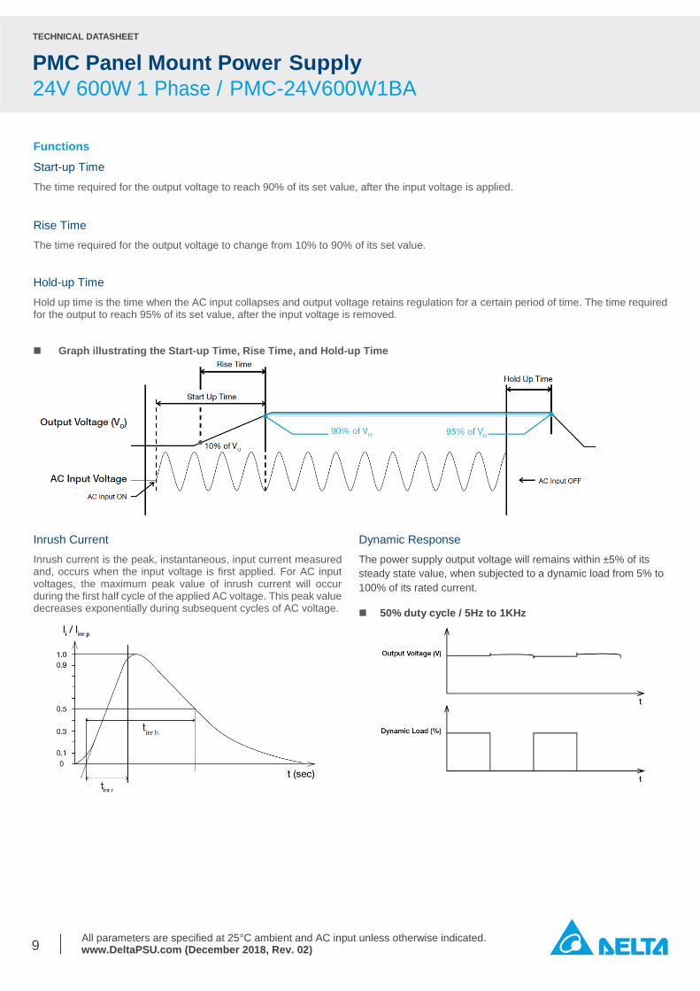
Functions
Start-up Time
The time required for the output voltage to reach 90% of its set value, after the input voltage is applied.
Rise Time
The time required for the output voltage to change from 10% to 90% of its set value.
Hold-up Time
Hold up time is the time when the AC input collapses and output voltage retains regulation for a certain period of time. The time required for the output to reach 95% of its set value, after the input voltage is removed. Graph illustrating the Start-up Time, Rise Time, and Hold-up Time
Inrush Current
Inrush current is the peak, instantaneous, input current measured and, occurs when the input voltage is first applied. For AC input voltages, the maximum peak value of inrush current will occur during the first half cycle of the applied AC voltage. This peak value decreases exponentially during subsequent cycles of AC voltage.
Dynamic Response
The power supply output voltage will remains within ±5% of its
steady state value, when subjected to a dynamic load from 5% to
100% of its rated current.
50% duty cycle / 5Hz to 1KHz

TECHNICAL DATASHEET
PMC Panel Mount Power Supply
24V 600W 1 Phase / PMC-24V600W1BA
All parameters are specified at 25°C ambient and AC input unless otherwise indicated. www.DeltaPSU.com (December 2018, Rev. 02)
10
Power Boost
𝐷𝑢𝑡𝑦 𝑐𝑦𝑐𝑙𝑒 (%) = 𝑇𝑃
𝑇𝑜𝑡𝑎𝑙 𝑇𝑖𝑚𝑒
𝐴𝑣𝑒𝑟𝑎𝑔𝑒 𝑂𝑢𝑡𝑝𝑢𝑡 𝑃𝑜𝑤𝑒𝑟 (𝑃𝐴𝑣𝑔) =(𝑃𝑜𝑤𝑒𝑟 𝐵𝑜𝑜𝑠𝑡 × 𝑇𝑃) + (𝑁𝑜𝑛-𝑃𝑒𝑎𝑘 𝑃𝑜𝑤𝑒𝑟 × 𝑇𝑁)
𝑇𝑜𝑡𝑎𝑙 𝑇𝑖𝑚𝑒
OR
𝑁𝑜𝑛-𝑃𝑒𝑎𝑘 𝑃𝑜𝑤𝑒𝑟 =(𝑃𝐴𝑣𝑔 × 𝑇𝑜𝑡𝑎𝑙 𝑇𝑖𝑚𝑒) − (𝑃𝑜𝑤𝑒𝑟 𝐵𝑜𝑜𝑠𝑡 × 𝑇𝑃)
𝑇𝑁
An example of Power Boost and Average Output Power
Power Boost Peak Power
(WP) Power Boost Duration (TP)
Duty Cycle Non-Peak
Power (WN) Non-Peak Power
Duration (TN) Total Time
(T)
200% 1200 5 sec 10% 533 45 sec 50 sec
200% 1200 5 sec 35% 277 9.3 sec 14.3 sec
180% 1080 10 sec 20% 480 40 sec 50 sec
180% 1080 10 sec 35% 348 19 sec 29 sec
150% 900 15 sec 30% 471 35 sec 50 sec
150% 900 15 sec 35% 438 28 sec 43 sec
124% 744 20 sec 40% 504 30 sec 50 sec
It is not recommended to prolong the duration of Power Boost to be longer than the specified duty cycle calculation, this may cause damage to the PSU.
Power Boost is the reserve power available constantly that allows reliable startup to support sudden and short spike of loads with high inrush current typically during turn on to remove the need of more expensive higher rated power supply unit. After the output has reached its steady state set value, the power supply can support surge loads with a higher short-term power demand up to 200% of maximum rated load (IO Max), for a maximum duration of 5 seconds. The Power Boost is also available to repeatedly basis with according to the condition of an average (R.M.S) output power shall not exceed continuous operating condition or refer to duty cycle calculation below.

TECHNICAL DATASHEET
PMC Panel Mount Power Supply
24V 600W 1 Phase / PMC-24V600W1BA
All parameters are specified at 25°C ambient and AC input unless otherwise indicated. www.DeltaPSU.com (December 2018, Rev. 02)
11
Overload & Overcurrent Protections
The power supply’s Overload (OLP) and Overcurrent (OCP) Protections will be activated when output current exceeds 180% of IO (Max load). In such occurrence, the VO will start to droop and once the power supply has reached its maximum power limit, the protection is activated and the power supply will go into “Hiccup mode” (Auto-Recovery). The power supply will recover once the fault condition of the OLP and OCP is removed and IO is back within the specifications.
It is not recommended to prolong the duration of IO when it is <180% but >100%, since it may cause damage to the PSU.
Short Circuit Protection
The power supply’s output OLP/OCP function also provides protection against short circuits. When a short circuit is applied, the output current will operate in “Hiccup mode”, as shown in the illustration in the OLP/OCP section on this page. The power supply will return to normal operation after the short circuit is removed.
Overvoltage Protection
The power supply’s overvoltage circuit will be activated when its internal feedback circuit fails. The output voltage shall not exceed its specifications defined on Page 3 under “Protections”. Overvoltage Protection (OVP) is Latch Mode.
Over Temperature Protection
As mentioned above, the power supply also has Over Temperature Protection (OTP). In the event of a higher operating temperature at 100% load, the power supply will run into OTP when the operating temperature is beyond what is recommended in the de-rating graph. When activated, the output voltage will go into latch mode until the mains is reapplied and the temperature drops to its normal operating temperature as recommended in the de-rating graph.

TECHNICAL DATASHEET
PMC Panel Mount Power Supply
24V 600W 1 Phase / PMC-24V600W1BA
All parameters are specified at 25°C ambient and AC input unless otherwise indicated. www.DeltaPSU.com (December 2018, Rev. 02)
12
Operating Mode
Redundancy Operation
In order to ensure proper redundancy operation for the power supply unit (PSU), ensure that the output voltage difference between the two units is kept at 0.45~0.50V for 24V supplies. Follow simple steps given below to verify: Step 1.
Measure output voltage of PSU 1 and PSU 2. If PSU 1 is the master unit, then VO of PSU 1 must be higher than PSU 2. In order to set the output voltage, connect the power supply to 50% load and set the PSU 1 and PSU 2 output voltage. Step 2.
Connect the right DRR module, 40A as per the system requirement to the power supply units PSU 1 and PSU 2 at Vin 1 & Vin 2 respectively. Step 3.
Connect the system load from Vout. Please note that output voltage Vout from DRR module will be = VO (output voltage of power supply) – Vdrop* (in DRR module). Parallel Operation
These DRR modules can also be used for Parallel function in order to increase the output power by N+1 (e.g. 2.5A + 2.5A = 5A or 2.5A + 2.5A + 2.5A = 7.5A) or current sharing, and thus increasing the power supply and system reliability. Though the PMC-24V600W1BA is not designed for current sharing, a good current sharing between two power supplies can be achieved by following simple steps as below (Refer to Fig. 3 for the Connection Diagram).
*Vdrop will vary from 0.60V to 0.90V (Typical 0.65V) depending on the load current and surrounding air temperature.
Fig. 3 Redundancy / Parallel Operation Connection Diagram
Step 1.
Set output load condition for both supplies at 50% and measure
the output voltages.
Step 2.
Adjust output voltages to the same level or within ±25mV
difference.
Step 3.
Connect PSU 1 and PSU 2 with the DRR-40A module and
measure at Vin 1 & Vin 2 to verify the voltage difference. Ensure
the voltages are within ±25mV.
Step 4.
Output voltage from DRR module Vout will be = VO (output voltage of power supply) – Vdrop* (in DRR module).

TECHNICAL DATASHEET
PMC Panel Mount Power Supply
24V 600W 1 Phase / PMC-24V600W1BA
All parameters are specified at 25°C ambient and AC input unless otherwise indicated. www.DeltaPSU.com (December 2018, Rev. 02)
13
Others
Delta RoHS Compliant
Restriction of the usage of hazardous substances
The European directive 2011/65/EU limits the maximum impurity level of homogeneous materials such as lead, mercury, cadmium, chrome, polybrominated flame retardants PBB and PBDE for the use in electrical and electronic equipment. RoHS is the abbreviation for “Restriction of the use of certain hazardous substances in electrical and electronic equipment”.
This product conforms to this standard.
PFC – Norm EN 61000-3-2
Line Current Harmonic content
Typically, the input current waveform is not sinusodial due to the periodical peak charging of the input capacitor. In industrial environment, complying with EN 61000-3-2 is only necessary under special conditions. Complying to this standard can have some technical drawbacks, such as lower efficiency as well as some commercial aspects such as higher purchasing costs. Frequently, the user does not profit from fulfilling this standard, therefore, it is important to know whether it is mandatory to meet this standard for a specific application.
Attention
Delta provides all information in the datasheets on an “AS IS” basis and does not offer any kind of warranty through the information for
using the product. In the event of any discrepancy between the information in the catalog and datasheets, the datasheets shall prevail
(please refer to www.DeltaPSU.com for the latest datasheets information). Delta shall have no liability of indemnification for any claim or
action arising from any error for the provided information in the datasheets. Customer shall take its responsibility for evaluation of using
the product before placing an order with Delta.
Delta reserves the right to make changes to the information described in the datasheets without notice.