pmd testing in modern networks” - het koninklijk instituut …€¦ · · 2016-09-16“pmd...
TRANSCRIPT


2 © 2016 EXFO Inc. All rights reserved.
Table of Contents
1 Quick review of PMD
2 Impacts & limits
3 Impact of coherent systems
4 Challenges/Reducing the risk
5 Solutions
3 © 2016 EXFO Inc. All rights reserved.
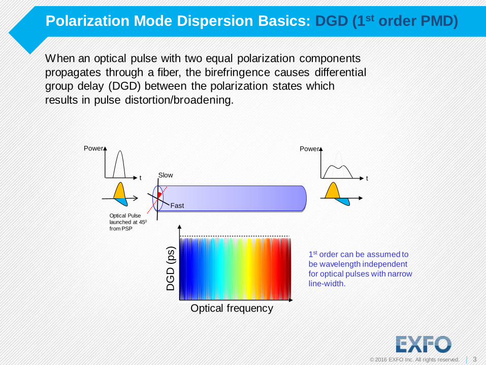
Polarization Mode Dispersion Basics: DGD (1st order PMD)
DG
D (
ps)
Optical frequency
t t
Power Power
Fast
Slow
When an optical pulse with two equal polarization components
propagates through a fiber, the birefringence causes differential
group delay (DGD) between the polarization states which
results in pulse distortion/broadening.
Optical Pulse
launched at 450
from PSP
1st order can be assumed to
be wavelength independent
for optical pulses with narrow
line-width.
4 © 2016 EXFO Inc. All rights reserved.
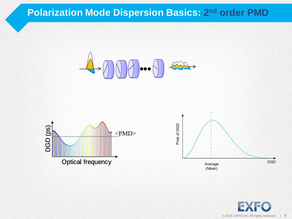
Polarization Mode Dispersion Basics: 2nd order PMD
DG
D (
ps)
Optical frequency
<PMD>
DG
D (
ps)
Optical frequency

5 © 2016 EXFO Inc. All rights reserved.
Impact of PMD on BER
5 5
Physical Layer
Transport Layer
“Business Layer”
6 © 2016 EXFO Inc. All rights reserved.
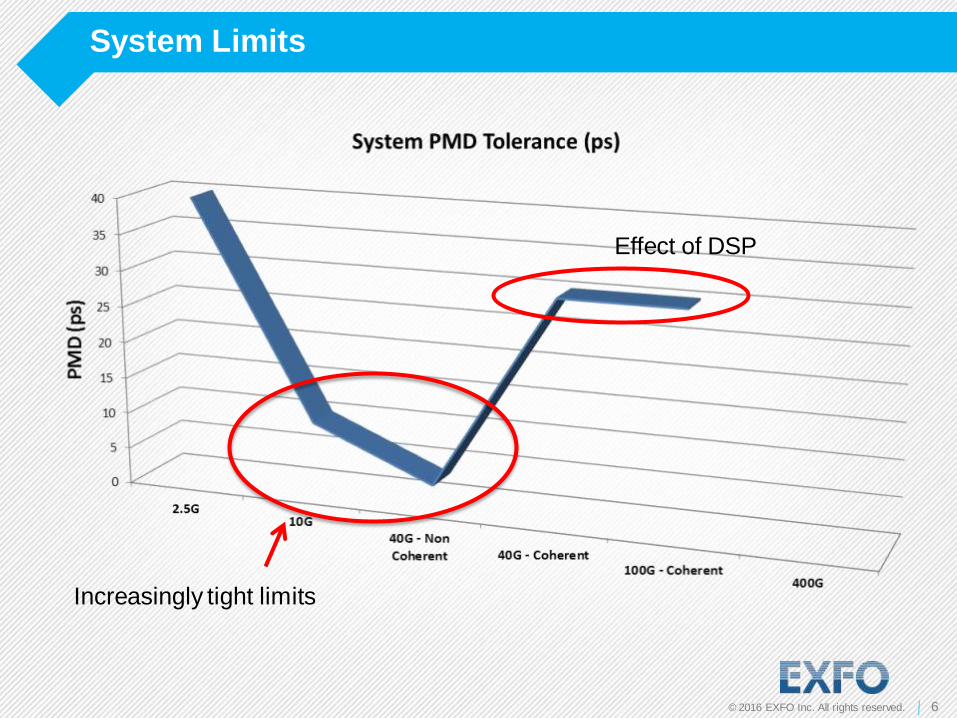
System Limits
Increasingly tight limits
Effect of DSP

7 © 2016 EXFO Inc. All rights reserved.
Coherent v/s Noncoherent
Coherent Receiver: contains a local oscillator (laser) for phase modulated signals (like DP-QPSK)
Polarization
controller
Signal
Local oscillator
Hybrid
Balanced
detector
Balanced
detector
ADC
DSP
Direct detection (noncoherent): contains a photodiode for on-off keying
signals
ADC
ADC
ADC

8 © 2016 EXFO Inc. All rights reserved.
PMD is also Random and not Deterministic in Real Fibers
Because of the dynamic nature of
PMD, it doesn't have a single fixed
value for a given section of fiber.
λ @ 1533.5 nm

9 © 2016 EXFO Inc. All rights reserved.
Polarization Varies with Time in Fiber-Optic Systems
Free space: Polarization does not change with time
Fiber: Stresses → fiber birefringence variation → State of polarization variations
Sources of fiber stress › Inherent asymmetry from manufacturing
› Temperature (Slow)
› Pressure (Slow)
› Macro/Micro bending (Slow)
› Wind-caused vibration (Fast)
› Mechanically induced acoustic vibration (Fastest)
Fairly
constant
Dynamic
and random

10 © 2016 EXFO Inc. All rights reserved..
High PMD Section
Vibration examples
High PMD Section
Fast changing Input
SOP

11 © 2016 EXFO Inc. All rights reserved.
Vibration examples
In central Europe ~30 strikes/100km OPGW

12 © 2016 EXFO Inc. All rights reserved.
Effect of vibration & shock
›Vibrations, thermal & mechanical shock may induce
›A very fast rate of change of PMD which the PMD tracking is unable to
keep up with.
›A PMD greater than the system can tolerate.
t
PMD
Time
Sudden PMD Jump

13 © 2016 EXFO Inc. All rights reserved.
Reducing the risk
›Plenty of 10G still being used and also now being used in new application
spaces (mobile back haul & Front haul, Metro, Broadband access)
›Even coherent systems are susceptible to fast PMD (changes) & very high
PMD.
Start with a low PMD network the probability of a PMD related impact is much
reduced.
Testing PMD is still vital as part of a links characterization.

14 © 2016 EXFO Inc. All rights reserved.
The Situation

15 © 2016 EXFO Inc. All rights reserved.
PMD Accumulation
Example: link built from concatenation of 4 fiber sections.
PMD for each section is: 15ps, 2ps, 1ps and 6ps.
PMDtotal2 = 225ps2 + 4ps2 + 1ps2 + 36ps2 = 266ps2
PMDtotal = sqrt(266) = 16.3ps
i
itotal PMDPMD 2
Remove 6 ps section … PMD = 15.2 ps (BAD)
vs.
Remove 15ps section … PMD = 6.4 ps (GOOD)
2 ps
6 ps 15 ps
1 ps
16 © 2016 EXFO Inc. All rights reserved.
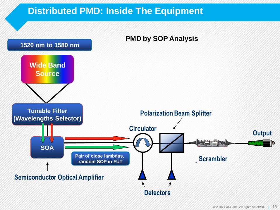
Distributed PMD: Inside The Equipment
Polarization Beam Splitter
1520 nm to 1580 nm
Pair of close lambdas,
random SOP in FUT Scrambler
Wide Band
Source
Tunable Filter
(Wavelengths Selector)
SOA
Detectors
Circulator
Semiconductor Optical Amplifier
Output
PMD by SOP Analysis
17 © 2016 EXFO Inc. All rights reserved.
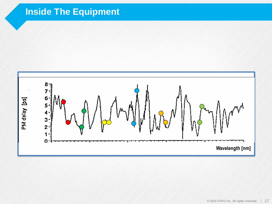
Inside The Equipment
Wavelength [nm]

18 © 2016 EXFO Inc. All rights reserved.
Inside The Equipment
• Repeat process at other Lambda Pairs & SOP’s
• Compute RMS Difference
•Uses Rayleigh Backscattering instead of end reflection
•And LOTS of data processing…!

19 © 2016 EXFO Inc. All rights reserved.
Output - Graph
OTDR trace
Cumulative PMD

20 © 2016 EXFO Inc. All rights reserved.
Output - Graph
Click on section
Details for that section

21 © 2016 EXFO Inc. All rights reserved.
Output – Contribution Histogram
22 © 2016 EXFO Inc. All rights reserved.
Conclusion
22
Modern coherent systems are very tolerant of PMD, but fast
changing or large abrupt changes may still cause problems.
Plenty of 10G being used and still being deployed.
Start with a low PMD network the probability of a PMD related
impact is much reduced.
Several tests in field can help identify PMD issues before they
happen and therefore reduce outage probability
Using standard PMD test equipment gives total PMD but no
indication where high PMD may be
Using distributed PMD equipment will help pinpoint any
problems.

23 © 2016 EXFO Inc. All rights reserved.
Thank You

24 © 2016 EXFO Inc. All rights reserved..
Plattegrond (Stand nummer 17)
24