p/n:110401103946x date:2018.06.26 rev
TRANSCRIPT
P/N:110401103946X DATE:2018.06.26REV.5

UT71A/B/C/D/E�使用说明书

UT71A/B/C/D/E 使用说明书
尊敬的用户:
您好!感谢您选购全新的优利德仪表,为了正确使用本仪表,请您在本仪表使用之前仔细阅读本说明书全文,特
别有关“安全注意事项”的部分。
如果您已经阅读完本说明书全文,建议您将此说明书进行妥善的保管,与仪表一同放置或者放在您随时可以查阅
的地方,以便在将来的使用过程中进行查阅。
序言

1
UT71A/B/C/D/E 使用说明书
一、概述二、UT71系列功能对照表三、开箱检查四、安全工作准则五、国际电气符号六、综合指标七、外形结构图八、旋钮开关及按键功能九、LCD显示器十、测量操作说明 1.交直流电压测量 2.交直流电流测量 3.电阻测量 4.电路通断测量 5.二极管测量 6.电容测量 7.频率/占空比测量 8.温度测量 9.(4~20mA)%测量
33445678911111213151617192021
�目录
�项目���������������������������������������页

2
UT71A/B/C/D/E 使用说明书
10.功率测量 11.电源档位 12.自动关机功能 13.按键功能定义十一、技术指标 1.直流电压测量 2.交流电压测量 3.直流电流测量 4.交流电流测量 5.电阻测量 6.电容测量 7.频率测量 8.二极管测量 9.电路通断测量 10.温度测量 摄氏温度 华氏温度 11.(4~20mA)% 测量 12.功率测量十二、保养和维修 1.一般的保养和维修 2.更换保险丝管 3.更换电池
2122222330303133343536373838393939404041414142
�项目���������������������������������������页

3
一、概述
UT71系列产品具有全功能模拟条图显示,全量程过载保护和独特的外观设计,使之成为性能更为优越的高精度电工测量仪表。 型号UT71A/B是20000计数4 1/2数位,自动量程真有效值数字万用表。 型号UT71C/D/E是40000计数4 3/4数位,自动量程真有效值数字万用表。 本系列仪表可用于测量:真有效值交流或(AC+DC)电压和电流、直流电压和电流、电阻、二极管、电路通断、电容、频率、占空比、温度、(4~20mA)%、有功功率、功率因数、视在功率、最大/最小值、相对测量等参数。并具有双重背光、用户设置、插错报警、USB数据传输、数据存储、数据保持、欠压显示和自动关机功能。 本使用说明书包括有关的安全信息和警告提示等,请仔细阅读有关内容并严格遵守所有的警告和注意事项。
二、UT71系列功能对照表:
本说明书的内容包括UT71系列所有产品功能、操作及指标,相应资料仅对有该功能的产品型号有效
UT71A/B/C/D/E 使用说明书
功能
最大显示
最高精度
数据存储
(4~20mA)%
温度
功率
UT71A
20000
±(0.1%+8)
UT71B
20000
±(0.05%+5)
100
√
√
UT71C
40000
±(0.025%+5)
100
√
√
UT71D
40000
±(0.025%+5)
9999
√
√
UT71E
40000
±(0.025%+5)
100
√
√
√

4
四、安全工作准则
本仪表严格遵循GB4793电子测量仪器安全要求以及
IEC61010-1安全标准进行设计和生产。符合双重绝缘
过电压标准CAT Ⅲ1000V 、CAT Ⅳ600V和污染等级Ⅱ的
安全标准。如果未能按照有关的操作说明使用仪表,
则可能会削弱或失去仪表为你提供的保护。
UT71A/B/C/D/E 使用说明书
使用前要检查仪表和表笔,谨防任何损坏或不正常
的现象,如果发现任何异常情况:表笔裸露、机壳
损坏、液晶显示器无显示等等,请不要使用。严禁
使用没有后盖和后盖没有盖好的仪表,否则有电击
危险。
表笔破损必须更换,并须换上同样型号或相同电气
规格的表笔。
当仪表正在测量时,不要接触裸露的电线、连接
器、没有使用的输入端或正在测量的电路。
测量高于直流60V或交流30V以上的电压时,务必小
心谨慎,切记手指不要超过表笔护指位,以防触
电。
1.
2.
3.
4.
三、开箱检查
打开包装盒取出仪表,请仔细检查下列附件是否缺
少或损坏,如发现有任何一项缺少或损坏,请即与你
的供应商联系。
lllll
llllll
使用说明书 一本
表笔 一副
带护套鳄鱼夹 一副
测试短线 一副
点式K型(镍铬~镍硅)热电偶(仅适用于230℃
以下温度的测量)(仅UT71B/C/D/E) 一个
USB接口连接线 一条
接口软件CD 一张
布包 一个
合格证 一张
功率测量转接器(仅UT71E) 一个
负载排插(仅UT71E) 一只

5
UT71A/B/C/D/E 使用说明书
在不能确定被测量值的范围时,须将功能量程开关
置于最大量程位置。
切勿在端子和端子之间,或任何端子和接地之间施
加超过仪表上所标注的额定电压或电流。
测量时功能开关必须置于正确的量程档位。在功能
量程开关转换之前,必须断开表笔与被测电路的连
接,严禁在测量进行中转换档位,以防损坏仪表。
进行在线电阻、二极管或电路通断测量之前,必须
先将电路中所有的电源切断,并将所有的电容器放
尽残余电荷。
测量电流以前,应先检查仪表的保险丝是否完好,
在仪表连接到电路上之前,应先将电路的电源关
闭。
不要在高温、高湿、易燃、易爆和强电磁场环境中
存放或使用仪表。
请勿随意改变仪表内部接线,以免损坏仪表和危及
安全。
当LCD显示器显示“ ”标志时,应及时更换电池,
以确保测量精度。
测量完毕应及时关断电源。长时间不用时,应取出
电池。
5.
6.
7.
8.
9.
10.
11.
12.
13.
五、国际电气符号
交流或直流
接地
警告注意安全标志
电池欠压
双重绝缘
符合欧洲工会(European Union)指令
美国电器质量标准UL

6
UT71A/B/C/D/E 使用说明书
电磁兼容性:在1V/m的射频场下:总精度=指定精度
+量程的5%,超过1V/m以上的射频场没有指定指标。
供电电源:6F22 9V
外形尺寸:177x85x40mm
重量:约340g(含电池)
安全标准: IEC 61010: CATⅢ1000V、CATⅣ600V
鉴定 、UL
12.
13.
14.
15.
16.
17.
六、综合指标信号输入端和COM端之间最大电压:详见各量程输入
保护电压说明
μA mA输入端子设有保险丝:(CE) 0.5A 250V快熔式
保险丝 5x20mm
A输入端子设有保险丝:(CE) 10A 250V快熔式保险
丝 5x20mm
显示:全字符及模拟条,最大读数为40000,每秒约
更新2~3次。
量程:自动
极性显示:自动
过量程提示:显OL〔在(4~20mA)%量程中显LO或
HI除外〕
电池欠压提示:
工作温度:0~40℃(32℉~104℉)
存储温度:-10~50℃(14℉~122℉)
相对湿度:0℃~30℃ ≤75%
30℃~40℃ ≤50%
1.
2.
3.
4.
5.
6.
7.
8.
9.
10.
11.

7
UT71A/B/C/D/E 使用说明书
七、外形结构图(见图1)
1.LCD显示窗
2.按键组
3.功能量程选择旋钮
4.输入端口
(图1)

8
UT71A/B/C/D/E 使用说明书
八、旋钮开关及按键功能
电源关机
直流电压测量
交流电压测量
直流毫伏电压测量
频率测量
频率信号占空比测量
电阻测量
二极管PN结电压测量
电路通断测量
电容测量
摄氏温度测量
华氏温度测量
μA交直流电流量程测量
mA交直流电流量程测量
10A交直流电流量程测量
(4~20mA)百分比测量
量程切换键
存储键
数据保持键
功能退出键
最大、最小值键
相对测试键
AC+DC键
附加功能选择键
设置键
回读数据键
左选择键
峰值保持键
右选择键
背光开关键
数据发送键
递减键
递增键
开关位置 功能说明
(4~20mA)%
OFF
℃
℉
Hz
%
RANGE
开关位置 功能说明
STORE
HOLD
EXIT
MAX MIN
REL
黄色按键
兰色按键
SETUP
RECALL
Peak HOLD
LIGHT
SEND
-
+

9
UT71A/B/C/D/E 使用说明书
九、LCD显示器(见图2)
(图2)
10
UT71A/B/C/D/E 使用说明书
序 号 符 号 说 明
1
2
3
4
5
6
7
8
9
10
11
12
13
14
15
16
17
18
MAX MIN
No.
℃
℉
SET
AC
DC
TrueRMS
Ω、kΩ、MΩ
MHz kHz Hz
mV、V
μA、mA、A
nF、μF、mF
STO
最大或最小值提示符
记录数据序号
温度单位: 摄氏度
温度单位: 华氏度
显示负的读数提示符
电池欠压提示符
功能设置提示符
交流测量提示符
直流测量提示符
真有效值提示符
电阻单位: 欧姆、千欧姆、兆欧姆
频率单位: 兆赫兹 千赫兹 赫兹
电压单位: 毫伏、伏
电流单位: 微安、毫安、安培
电容单位: 纳法、微法、毫法
自动关机功能提示符
电路通断测量提示符
数据存储提示符
序 号 符 号 说 明
数据回读提示符
相对测量REL提示符
数据设置下限值提示符
自动量程提示符
数据发送提示符
背光功能提示符
数据保持提示符
峰值数据保持提示符
数据设置上限值提示符
二极管测量提示符
超量程提示符
频率信号占空比测量或(4~
20mA) 百分比测量提示符
提供当前输入的模拟指针显示
功率因数提示符
视在功率提示符
有功功率提示符
19
20
21
22
23
24
25
26
27
28
29
30
31
32
33
34
RCL
LOW
AUTO
SEND
HOLD
PEAK HOLD
HIGH
OL
%
模拟条显示器
COSф
VA
W

11
UT71A/B/C/D/E 使用说明书
十、测量操作说明
(图3)
将红表笔插入“V”插孔,黑表笔插入“COM”插孔。将功能量程开关置于 直流电压测量档或 交流电压测量档或 直流毫伏电压测量档,并将表笔并联到待测电源或负载上。从显示器上直接读取被测电压值。交流测量显示值为真有效值。仪表的输入阻抗在 和 功能约为10MΩ,在 功能输入阻抗约为2GΩ,这种负载在高阻抗的电路中会引起测量上的误差。大部分情况下,如果电路阻抗在10kΩ以下,误差可以忽略 (0.1%或更低)。
1.
2.
3.
4.
注意:l
ll
不要输入高于1000V的电压。测量更高的电压是有可能的,但有损坏仪表的危险。在测量高电压时,要特别注意避免触电。 在完成所有的测量操作后,要断开表笔与被测电路的连接。
1.交直流电压测量(见图3)
红 黑

12
UT71A/B/C/D/E 使用说明书
2.交直流电流测量(见图4)
(图4)
将红表笔插入“μA、mA”或“A”插孔,黑表笔插入“COM”插孔。将功能量程开关置于电流测量档,按兰色键选择所需测量的交流或直流电流,并将仪表表笔串联到待测回路中。从显示器上直接读取被测电流值,交流测量显示值为真有效值。
1.
2.
3.
注意:
l
l
l
l
l
在仪表串联到待测回路之前,应先将回路中的电源关闭。测量时应使用正确的输入端口和功能档位,如不能估计电流的大小,应从大电流量程开始测量。≤5A允许连续测量;5A~10A连续测量时间,为了安全使用,每次测量时间应≤10秒,间隔时间应大于15分钟。当表笔插在电流输入端口上时,切勿把表笔测试针并联到任何电路上,会烧断仪表内部保险丝和损坏仪表。在完成所有的测量操作后,应先关断电源再断开表笔与被测电路的连接。对大电流的测量更为重要。
黑 红
13
UT71A/B/C/D/E 使用说明书
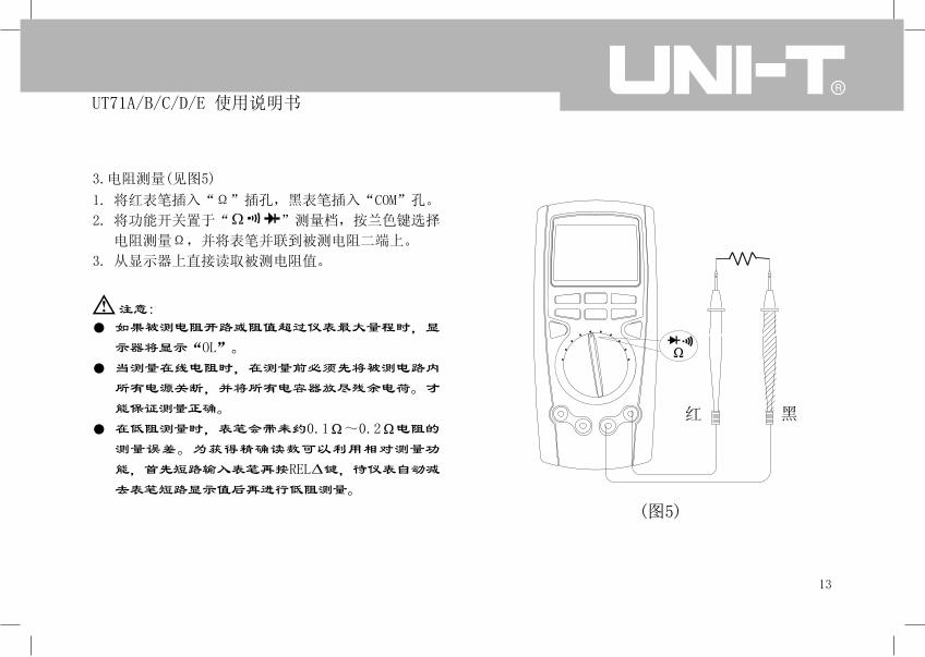
3.电阻测量(见图5)
(图5)
将红表笔插入“Ω”插孔,黑表笔插入“COM”孔。
将功能开关置于“ ”测量档,按兰色键选择
电阻测量Ω,并将表笔并联到被测电阻二端上。
从显示器上直接读取被测电阻值。
1.
2.
3.
注意:
l
l
l
如果被测电阻开路或阻值超过仪表最大量程时,显
示器将显示“OL”。
当测量在线电阻时,在测量前必须先将被测电路内
所有电源关断,并将所有电容器放尽残余电荷。才
能保证测量正确。
在低阻测量时,表笔会带来约0.1Ω~0.2Ω电阻的
测量误差。为获得精确读数可以利用相对测量功
能,首先短路输入表笔再按REL 键,待仪表自动减
去表笔短路显示值后再进行低阻测量。
红 黑

14
UT71A/B/C/D/E 使用说明书
l
l
l
l
测量1MΩ以上的电阻时,可能需要几秒钟后读数才
会稳定。这对于高阻的测量属正常。为了获得稳定
读数可用测试短线进行测量。
不要输入高于直流60V或交流30V以上的电压,避免
伤害人身安全。
在完成所有的测量操作后,要断开表笔与被测电路
的连接。
测量非固定电阻时,请按下RANGE键开机,使用仪
表的模拟电阻信号测量模式,此测量模式下仪表最
后一位数字不显示,测量精度不变。
15
UT71A/B/C/D/E 使用说明书
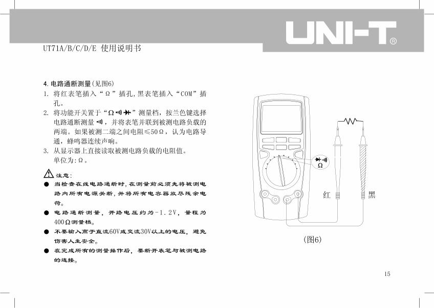
4.电路通断测量(见图6)
将红表笔插入“Ω”插孔,黑表笔插入“COM”插
孔。
将功能开关置于“ ”测量档,按兰色键选择
电路通断测量 ,并将表笔并联到被测电路负载的
两端。如果被测二端之间电阻≤50Ω,认为电路导
通,蜂鸣器连续声响。
从显示器上直接读取被测电路负载的电阻值。
单位为:Ω。
1.
2.
3.
注意:
l
l
l
l
当检查在线电路通断时,在测量前必须先将被测电
路内所有电源关断,并将所有电容器放尽残余电
荷。
电路通断测量,开路电压约为-1.2 V,量程为
400Ω测量档。
不要输入高于直流60V或交流30V以上的电压,避免
伤害人生安全。
在完成所有的测量操作后,要断开表笔与被测电路
的连接。
(图6)
红 黑
16
UT71A/B/C/D/E 使用说明书
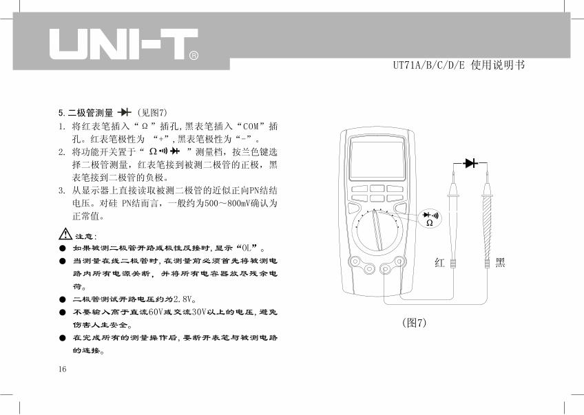
5.二极管测量�����(见图7)
将红表笔插入“Ω”插孔,黑表笔插入“COM”插
孔。红表笔极性为 “+”,黑表笔极性为“-”。
将功能开关置于“ ”测量档,按兰色键选
择二极管测量,红表笔接到被测二极管的正极,黑
表笔接到二极管的负极。
从显示器上直接读取被测二极管的近似正向PN结结
电压。对硅 PN结而言,一般约为500~800mV确认为
正常值。
1.
2.
3.
注意:
ll
ll
l
如果被测二极管开路或极性反接时,显示“OL”。
当测量在线二极管时,在测量前必须首先将被测电
路内所有电源关断,并将所有电容器放尽残余电
荷。
二极管测试开路电压约为2.8V。
不要输入高于直流60V或交流30V以上的电压,避免
伤害人生安全。
在完成所有的测量操作后,要断开表笔与被测电路
的连接。
(图7)
红 黑

17
UT71A/B/C/D/E 使用说明书
6.电容测量(见图8)
将红表笔插入“ ”插孔,黑表笔插入“COM”插
孔。
将量程开关置于“ ”档位,此时仪表可能会显
示一个固定读数,此数为仪表内部的分布电容值。
对小于10nF电容的测量,被测量值一定要减去此
值,才能确保测量精度。在测量中可以利用相对测
量功能,首先按REL 键,待仪表自动减去开路显示
值后再进行小电容测量。
建议用测试短线输入进行电容测量,可以减小分布
电容的影响。
1.
2.
3.
(图8)
红 黑

18
UT71A/B/C/D/E 使用说明书
注意:
l
l
l
l
如果被测电容短路或容值超过仪表的最大量程
时,显示器将显示“OL”。
电容测量模式下模拟条指针被禁止。对于大于
400μF电容的测量,会需要较长的时间,此时模拟
条指针会指示完成测量过程的存余时间,便于正确
读数。
为了确保测量精度,在测量过程中仪表内部会对被
测电容进行放电,在放电模式下LCD会显示“DIS.
C”,但放电过程较慢。建议电容在测试前将电容
全部放尽残余电荷后再输入仪表进行测量,对带有
高压的电容更为重要,避免损坏仪表和伤害人身安
全。
在完成测量操作后,要断开表笔与被测电容的连
接。
19
UT71A/B/C/D/E 使用说明书
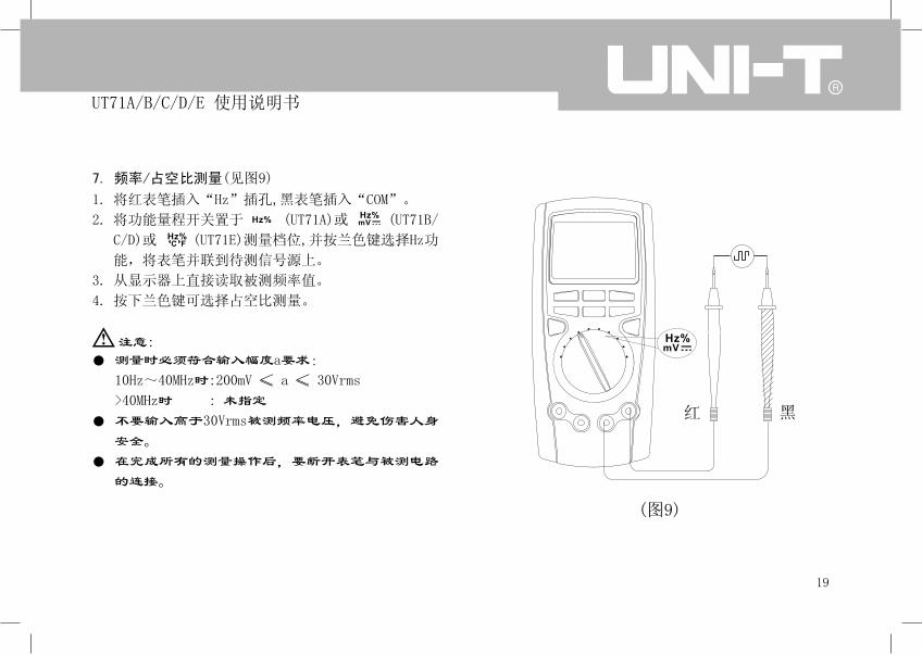
7.�频率/占空比测量(见图9)
将红表笔插入“Hz”插孔,黑表笔插入“COM”。
将功能量程开关置于 (UT71A)或 (UT71B/
C/D)或 (UT71E)测量档位,并按兰色键选择Hz功
能,将表笔并联到待测信号源上。
从显示器上直接读取被测频率值。
按下兰色键可选择占空比测量。
1.
2.
3.
4.
注意:
l
l
l
测量时必须符合输入幅度a要求:
10Hz~40MHz时:200mV ≤ a ≤ 30Vrms
>40MHz时 : 未指定
不要输入高于30Vrms被测频率电压,避免伤害人身
安全。
在完成所有的测量操作后,要断开表笔与被测电路
的连接。
(图9)
红 黑

20
UT71A/B/C/D/E 使用说明书
8.温度测量(见图10)
将量程开关置于“℃℉”档位,此时LCD显示OL,短
路表笔则显示室温。
将温度K型插头按图示插入对应孔位。
将温度探头探测被测温度表面,数秒后从LCD上直
接读取被测温度值。
按下兰色键可选择摄氏温度、华氏温度测量。
1.
2.
3.
4.
注意:
l
l
ll
仪表所处环境温度不得超出18-23℃范围之外,否
则会造成测量误差,在低温环境测量更为明显。
不要输入高于直流60V或交流30V以上的电压,避免
伤害人身安全。
在完成所有的测量操作后,取下温度探头。
点式K型(镍铬~镍硅)热电偶(仅适用于230℃以下
温度的测量)。
(图10)
21
UT71A/B/C/D/E 使用说明书
9.(4~20mA)%测量
将量程开关置于“ ”档位,按兰色键选择 (4~
20mA)% 功能,测试方法类同直流电流测量(见图4);4~
20mA范围按百分比显示∶<4mA显LO;4mA显0%; 20mA显
100%;>20mA显HI。
%4-20mA
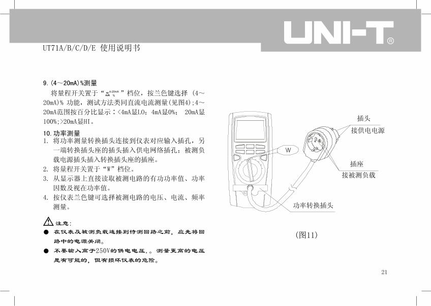
10.功率测量将功率测量转换插头连接到仪表对应输入插孔,另
一端转换插头座的插头插入供电网络插孔;被测负
载电源插头插入转换插头座的插座。
将量程开关置于“W”档位。
从显示器上直接读取被测电路的有功功率值、功率
因数及视在功率值。
按仪表兰色键可选择被测电路的电压、电流、频率
测量。
1.
2.
3.
4.
注意:
l
l
在仪表及被测负载连接到待测回路之前,应先将回
路中的电源关闭。
不要输入高于250V的供电电压,。测量更高的电压
是有可能的,但有损坏仪表的危险。
插头
接供电电源
插座
接被测负载
功率转换插头
(图11)
22
UT71A/B/C/D/E 使用说明书
11.电源档位(OFF)
仪表关闭电源。
12.自动关机功能
当仪表在用户设定的关机时间(仪表默认10分钟)
内没有转动旋钮开关或按键动作,显示器将消隐显
示,随即仪表进入微功耗休眠状态。如要唤醒仪表重
新工作,只要按一次兰色按键即可,转动旋钮开关也
能唤醒仪表。
l
ll
被测负载最大电流不得>10A,≤5A允许连续测量;
5A~10A连续测量时间,为了安全使用,每次测量
时间应≤10秒,间隔时间应大于15分钟。
在测量时,要特别注意避免触电。
在完成所有的测量操作后,应先关断电源再移开转
换插头座的插头与供电网络插孔的连接。

23
UT71A/B/C/D/E 使用说明书
13.按键功能定义
按 键 功能定义
按RANGE键仪表由自动量程转入手动当前量程模式,提示符“Auto”消隐。
每按一次递增一个量程;依次循环。按 EXIT 键即退出手动量程模式,恢复原始测量模式,
仪表默认“Auto”自动量程模式。
按下此键开机,仪表进入模拟电阻信号测量模式
按SETUP键进入设置状态,按SETUP依次循环设置项目 :选择可修改位;+ -:修改设定值;
EXIT:保存设定值;具体见设置操作详表
第一次按下STORE键,左小显示当前存储记录数,按 键切换选择清除原有记录并从1条记录开始或从
当前记录号开始存储;右小显示原有记录条数. 提示符显示:“STO”,“no. xxxx”
第二次按下STORE键,左小显示自动记录间隔时间秒数,默认0秒即不自动记录,按+/-可设置间隔时
间(长按时为快速设置) (最大255秒),提示符显示:“STO”,“s”
第三次按下STORE键,左小显示:递增一个存储记录序号xxxx、右小显示:对应存储序号的在线测量
值xxxx、主显示:在线测量值 xxxx 。若选择了间隔时间,仪表将自动存储测量记录。若没有选择间
隔时间每按一次STORE增加存储一条记录。自动增加记录时,增加到本表所能够存储的最大记录后停
止。提示符显示:“STO”,“no. xxxx”

24
UT71A/B/C/D/E 使用说明书
按 键 功能定义
按EXIT退出并确认存储记录,若不按此键直接关机,则丢失本次操作存储数据;
进入此功能后,仪表将关闭自动关机功能。
按RECALL键,回读存储数据。提示符显示“RCL”
左上小显示:显示存储序号“no.xxxx”;主显示:显示存储序号对应的存储数据;右小显示总存
储数据条数;按 键,自动打开SEND功能,将所有存储数据通过USB快速发送到电脑接口软件。通
过电脑接口软件,可显示记录存储时间与记录值。所有数据发送完成后,仪表将自动关闭SEND功能;
按 + / - 键,循环回读上/下一条记录。(长按为快速回读)
按 EXIT 键即退出
在SETUP模式下按“ ”键,见设置操作详表
按下HOLD保持键仪表停止更新显示,提字符:“HOLD”显示。
按EXIT键即退出HOLD模式,恢复原始测量模式。
按下Peak HOLD峰值保持键,仪表进入峰值保持状态,提字符:“Peak”显示。
按 EXIT 键即退出
在SETUP模式下按“ ”键,见设置操作详表

25
UT71A/B/C/D/E 使用说明书
按 键 功能定义
执行退出功能。
按下此键开机,仪表恢复出厂设置值。
按下LIGHT则进入一级背光(设定的时间后熄灭),再按则进入二级背光,(设定的时间后熄灭)。
按 EXIT 键即退出
当按下MAX/MIN 键时,开始以约每秒2次采样速率进入MAX MIN记录模式。
左上小显示:显示最大值及提示符MAX;右上小显示:显示最小值及提示符MIN;主显示:显示在线
测量值。
再按一次MAX MIN键,左上小显示:在线测量值;右上小显示:显示最小值及提示符MIN;主显示:显
示最大值。
再按一次MAX MIN键,左上小显示:在线测量值;右上小显示:显示最大值及提示符MAX;主显示:显
示最小值。
按MAX MIN键可依次循环显示以上三种模式。在以上状态下自动关闭“Auto”模式及提示符。
按 EXIT 键即可退出MAX / MIN模式,恢复原始测量模式。
在MAX/MIN模式下,按下HOLD键可使仪表停止更新数据。

26
UT71A/B/C/D/E 使用说明书
按 键 功能定义
将USB接口连接线插入仪表背面靠上位置红外发射窗口卡位,按下此键,启动SEND通讯接口输出,并
显示提示符“SEND”; 同时关闭自动关机功能
按 EXIT 键即退出;仪表电脑接口软件操作详见软件光盘中“接口软件操作说明”
“-”在 SETUP 或RECALL模式下可递减设定值。
按下 RELΔ键即进入相对测量模式,显示提示符“Δ”,
左上小显示:显示测量值;右上小显示相对值;主显示:显示测量值-相对值。
按 EXIT 键即退出RELΔ模式,恢复原始测量模式。
“+”在 SETUP 或RECALL模式下可递增设定值。
按蓝色键键能选择循环切换主/辅测试功能,
仪器进行睡眠状态后,按下此键仪器将回到正常测试模式;
按下此键开机,则仪器进入快速测试模式,此模式无最后一位数字显示
此键为锁定按键,在AC测量时,按下AC+DC,则进入AC+DC测量模式,显示“AC+DC”

27
UT71A/B/C/D/E 使用说明书
按键操作举例说明:
单击:STORE; 长按超过1秒:RECALL; 进入复加按键后单击:
设置操作详表按下SETUP键进入仪表设置操作功能,通过 +/- 调整设置值;EXIT 保存设置值;
带*值为本机默认值建议用户设置操作前先将仪表置在DCV功能
提示符 设定值 备 注
HIGH
LOW
4 0 0 0 0
OFF *
4 0 0 0 0
OFF *
1 0 *
2 0
3 0
0 FF
1 *
0 FF
超上限值蜂鳴间断声响报警
设置成“OFF” 选择调整位
超下限值蜂鳴间断声响报警
设置成“OFF” 选择调整位
10分钟自动关机
20分钟自动关机
30分钟自动关机
关闭自动关机功能
连续发声,提示符长亮
关闭发声,提示符同步闪烁
模拟条
1 0 *
2 0
3 0
0FF
左边零 *
中心零
背光点亮时间设置10秒
背光点亮时间设置20秒
背光点亮时间设置30秒
取消背光功能
设置左边零
设置中心零(仅适用于:DC V 、
DC I 、°C/°F功能)
提示符 设定值 备 注
0 1 2 3 4
-4 -2 0 2 4

28
UT71A/B/C/D/E 使用说明书
功 能 主 显 右上小显
DCV
ACV
DCmV
Ω
Hz
℃
℉
DCμA
ACμA
DCmA
ACmA
被测电压值
被测电压值
被测电压值
被测电阻值
被测电阻值
被测电压值
被测频率值
被测电容值
被测℃值
被测℉值
被测电流值
被测电流值
被测电流值
被测电流值
功能与显示对照
左上小显
被测频率值:45.00Hz~100.0kHz
被测频率值:45.00Hz~10.00kHz
被测频率值:45.00Hz~10.00kHz
滿量程值:4;40;400;1000
滿量程值:4;40;400;1000
滿量程值:400
滿量程值:400;4;40;400;4;40
滿量程值:400
滿量程值:4
滿量程值:40;400;4;40;400;4;40;400
滿量程值:40;400;4;40;400;4;40
滿量程值:1000
滿量程值:1832
滿量程值:400;4000
滿量程值:400;4000
滿量程值:40;400
滿量程值:40;400

29
UT71A/B/C/D/E 使用说明书
功 能 主 显 右上小显
DCA
ACA
W
STO
RCL
MAX MIN
RELΔ
被测电流值
被测电流值
被测有功功率
在线测量值
存储数据值
在线测量值
测量值-相对值
左上小显
被测频率值:45.00Hz~10.00kHz
视在功率
当前存储值
总存储数据条数
相对值
滿量程值:10
滿量程值:10
功率因数
存储序号:no.0001~no.0100
存储序号:no.0001~no.0100
测量值
最大值或最小值最小值或最大值将根据按键功能定义相应显示
以上说明以UT71C为例,其他型号参考其最大显示值。

30
UT71A/B/C/D/E 使用说明书
十一、技术指标误差极限: ±(a%读数+字数),保证期一年
环境温度: 18~28℃
环境湿度: 不大于75%RH
1.直流电压测量
量 程 分辩力误差极限:±(%读数+字数)
200mV
2V
20V
200V
1000V
0.01mV
0.0001V
0.001V
0.01V
0.1V
输入阻抗:200mV/400mV约2.5GΩ 其他均约为10MΩ
过载保护:1000V
UT71A UT71B UT71C/D/E量 程 分辩力
误差极限:±(%读数+字数)
400mV
4V
40V
400V
1000V
0.01mV
0.0001V
0.001V
0.01V
0.1V
±(0.1%+8)
±(0.1%+8)
±(0.15%+8)
±(0.05%+5)
±(0.08%+5)
±(0.1%+8)
±(0.025%+5)
±(0.05%+5)
±(0.1%+8)

31
UT71A/B/C/D/E 使用说明书
2.交流电压测量�(可AC+DC测量)
量 程 分辩力误差极限:±(%读数+字数)
2V
20V
200V
1000V
UT71A UT71B
0.0001V
0.001V
0.01V
0.1V
45Hz~1kHz
1kHz~10kHz
10kHz~100kHz
45Hz~1kHz
1kHz~10kHz
10kHz~100kHz
45Hz~1kHz
1kHz~10kHz
10kHz~100kHz
45Hz~1kHz
1kHz~5kHz
5kHz~10kHz
±(0.8%+40)
±(3%+40)
±(7%+40)
±(0.8%+40)
±(3%+40)
±(7%+40)
±(0.8%+40)
±(5%+40)
参考
±(1.5%+40)
±(6%+40)
±(10%+40)
±(0.6%+40)
±(3%+40)
±(7%+40)
±(0.6%+40)
±(3%+40)
±(7%+40)
±(0.6%+40)
±(5%+40)
参考
±(1.2%+40)
±(6%+40)
±(10%+40)
频率范围 量 程 分辩力误差极限:±(%读数+字数)
4V
40V
400V
1000V
UT71C/D/E
0.0001V
0.001V
0.01V
0.1V
45Hz~1kHz
1kHz~10kHz
10kHz~100kHz
45Hz~1kHz
1kHz~10kHz
10kHz~100kHz
45Hz~1kHz
1kHz~10kHz
10kHz~100kHz
45Hz~1kHz
1kHz~5kHz
5kHz~10kHz
±(0.4%+30)
±(3%+30)
±(6%+30)
±(0.4%+30)
±(3%+30)
±(6%+30)
±(0.4%+30)
±(5%+30)
参考
±(1%+30)
±(5%+30)
±(10%+30)
频率范围

32
UT71A/B/C/D/E 使用说明书
输入阻抗:约10MΩ
过载保护:1000V
显示:1)真有效值(适用於量程的10%至100%)。
2)交流波峰因素3.0 (1000V量程为1.5)
3)输入短路允许有80个字剩余读数。
5)频率小于100kHz时,精度保证范围10%-100%。
5)AC+DC测量时,在原误差极限上±(1%+35)。

33
UT71A/B/C/D/E 使用说明书
3.直流电流测量
量 程 分辩力误差极限:±(%读数+字数)
200μA
2000μA
20mA
200mA
10A
0.01μA
0.1μA
0.001mA
0.01mA
0.001A
UT71A UT71B
±(0.2%+20)
±(0.8%+30)
±(0.15%+20)
±(0.7%+30)
注意:10A量程:≤5A允许连续测量;5A~10A连续测量时间应≤10秒,间隔时间应≥15分钟。
过载保护: μA mA量程: 保险丝φ5×20mm F0.5A 250V (CE)
10 A量程: 保险丝φ5×20mm F10A 250V (CE)
量 程 分辩力误差极限:±(%读数+字数)
400μA
4000μA
40mA
400mA
10A
0.01μA
0.1μA
0.001mA
0.01mA
0.001A
UT71C/D/E
±(0.1%+15)
±(0.15%+15)
±(0.5%+30)

34
UT71A/B/C/D/E 使用说明书
4.交流电流测量
量 程 分辩力误差极限:±(%读数+字数)
200μA
2000μA
20mA
200mA
10A
UT71A UT71B
0.01μA
0.1μA
0.001mA
0.01mA
0.001A
45Hz~1kHz
1kHz~10kHz
45Hz~1kHz
1kHz~10kHz
±(1%+15)
±(2%+40)
±(2%+20)
±(6%+40)
±(0.8%+15)
±(1.5%+40)
±(2%+20)
±(6%+40)
频率范围 量 程 分辩力误差极限:±(%读数+字数)
400μA
4000μA
40mA
400mA
10A
UT71C/D/E
0.01μA
0.1μA
0.001mA
0.01mA
0.001A
45Hz~1kHz
1kHz~10kHz
45Hz~1kHz
1kHz~10kHz
±(0.7%+15)
±(1%+40)
±(1.5%+20)
±(5%+40)
频率范围
显示:1)真有效值(适用於量程的10%至100%)。 2)交流波峰因素3.0。 3)短路允许有80个字剩余读数。 4)频率小于10kHz时,精度保证范围10%-100%。 5)AC+DC测量时,在原误差极限上±(1%+35)过载保护:μA mA量程: 保险丝φ5×20mm F0.5A 250V (CE) 10A量程 : 保险丝φ5×20mm F10A 250V (CE)
注意:10A量程:≤5A允许连续测量;5A~10A连续测量时间应≤10秒,间隔时间应≥15分钟。

35
UT71A/B/C/D/E 使用说明书
过载保护:1000V
5.电阻测量
量 程 分辩力误差极限:±(%读数+字数)
200Ω
2kΩ
20kΩ
200kΩ
2MΩ
20MΩ
0.01Ω
0.0001kΩ
0.001kΩ
0.01kΩ
0.0001MΩ
0.001MΩ
UT71A UT71B
±(0.5%+20)
+表笔短路值
±(1%+20)
±(1%+40)
±(1.5%+40)
±(0.4%+20)
+表笔短路值
±(0.8%+20)
±(1%+40)
±(1.5%+40)
量 程 分辩力
400Ω
4kΩ
40kΩ
400kΩ
4MΩ
40MΩ
0.01Ω
0.0001kΩ
0.001kΩ
0.01kΩ
0.0001MΩ
0.001MΩ
UT71C/D/E
±(0.3%+8)
+表笔短路值
±(0.5%+20)
±(1%+40)
±(1.5%+40)
误差极限:±(%读数+字数)
±(0.3%+8)±(0.5%+20) ±(0.4%+20)

36
UT71A/B/C/D/E 使用说明书
过载保护:1000V
6.电容测量
量 程 分辩力误差极限:±(%读数+字数)
20nF
200nF
2μF
20μF
200μF
2mF
20mF
0.001nF
0.01nF
0.0001μF
0.001μF
0.01μF
0.0001mF
0.001mF
UT71A UT71B
±(1.5%+20)
+表笔开路电容值
±(1.5%+40)
±(1.5%+40)
±(5%+40)
参考
±(1.2%+20)
+表笔开路电容值
±(1.2%+40)
±(1.5%+40)
±(5%+40)
参考
量 程 分辩力误差极限:±(%读数+字数)
40nF
400nF
4uF
40uF
400uF
4mF
40mF
0.001nF
0.01nF
0.0001μF
0.001μF
0.01μF
0.0001mF
0.001mF
UT71C/D/E
±(1%+20)
+表笔开路电容值
±(1%+20)
±(1.2%+20)
±(5%+20)
参考
±(1.5%+20) ±(1.2%+20)
37
UT71A/B/C/D/E 使用说明书
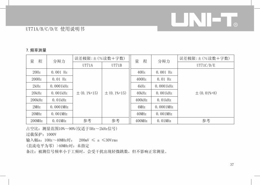
占空比:测量范围10%~90%(仅适于5Hz~2kHz信号)
过载保护:1000V
输入幅a:10Hz~40MHz时: 200mV ≤ a ≤30Vrms
(直流电平为零) >40MHz时:未指定
备注:被测信号频率小于工频时,会受干扰出现轻微跳数,但不影响正常测量。
7.频率测量
量 程 分辩力误差极限:±(%读数+字数)
20Hz
200Hz
2kHz
20kHz
200kHz
2MHz
20MHz
200MHz
0.001 Hz
0.01 Hz
0.0001kHz
0.001kHz
0.01kHz
0.0001MHz
0.001MHz
0.01MHz
UT71A UT71B
±(0.1%+15)
参考
±(0.1%+15)
参考
量 程 分辩力误差极限:±(%读数+字数)
40Hz
400Hz
4kHz
40kHz
400kHz
4MHz
40MHz
400MHz
0.001 Hz
0.01 Hz
0.0001kHz
0.001kHz
0.01kHz
0.0001MHz
0.001MHz
0.01MHz
UT71C/D/E
±(0.01%+8)
参考

38
UT71A/B/C/D/E 使用说明书
8.二极管测量
量 程 分辩力 备注(UT71A/B/C/D/E)
0.0001V 开路电压约2.8V,硅PN结正常电压值约为0.5~0.8V
过载保护:1000V
9.电路通断测量
量 程 分辩力
0.01Ω开路电压约为-1.2V;电路断开电阻值设定为:>60Ω,蜂鸣器不发
声;电路良好导通阻值设定为:≤40Ω,蜂鸣器连续发声
过载保护:1000V
备注(UT71A/B/C/D/E)

39
UT71A/B/C/D/E 使用说明书
过载保护:1000V
温度传感器:适用K型(镍铬~镍硅)热电偶。
附件为点式K型(镍铬~镍硅)热电偶,仅适用于230℃以下温度的测量。
量 程 分辩力误差极限:±(%读数+字数)
-40℉~32℉
32℉~752℉
752~1832℉
0.1℉
±(4%+50)
±(1.5%+50)
±3%
华氏温度
UT71A UT71B/C/D/E
10.温度测量(UT71B/C/D/E)
量 程 分辩力误差极限:±(%读数+字数)
-40℃~40℃
40~400℃
400~1000℃
0.1℃
±(3%+30)
±(1%+30)
±2.5%
摄氏温度
UT71A UT71B/C/D/E

40
UT71A/B/C/D/E 使用说明书
11.(4~20mA)% 测量(UT71B/C/D/E)
备注:4~20mA范围按百分比显示: <4mA显LO;4mA显0%~20mA显100%;>20mA显HI。
过载保护:保险丝φ5×20mm F0.5A 250V (CE)
量 程 分辩力误差极限:±(%读数+字数)
UT71A UT71B/C/D/E
(4~20mA)% 0.01% ±(1%+50)
12.功率测量(UT71E)
功率测量:
功率因数输入范围:0.00~1.00;电压输入阻抗:约为10MΩ;
输入值小于量程10%时,误差加3W;
电压输入范围:AC50~250V;电压过载保护:1000V;
电流过载保护:保险丝φ5×20mm F10A 250V (CE)。
量 程 分辩力 误差极限:±(%读数+字数)
±(2%+10)
±(2%+10)
±(1%+10)
±(1%+10)
1
0.1
0.001
2500W
2500W
0~1
VA视在功率
W有功功率
Cosφ
按兰色键切换:主显示频率、左小显示电流、右小显示电压
41
UT71A/B/C/D/E 使用说明书
十二、保养和维修
警告:
在打开仪表后盖之前,应确定电源已关闭;表笔已离
开输入端口和被测电路。
l
l
l
l
l
清洁仪表只能使用湿布和少量洗涤剂,切忌用化学
溶剂擦拭表壳。
如发现仪表有任何异常,应立即停止使用并送维
修。
在有需要对仪表进行校验或维修时,请由有资格的
专业维修人员或指定的维修部门修。
不使用时应关断仪表的电源,长期不用时应取出电
池。
存放仪表应避免潮湿,高温和强电磁场。
1.一般的保养和维修��
2.更换保险丝管(见图12)�
警告:
为避免仪表错误的显示而导致受到电击或人身伤害。
在测量电流时,仪表显示毫无反应,应立即检查仪表
内置相关保险丝管有无被烧断,如确认保险丝管已被
烧断,应立即按原规格更换保险丝管。
保险丝管规格:F1�0.5A�250V快熔式保险丝��5x20mm�
�������������F2��10A�250V快熔式保险丝��5x20mm
操作步骤:
1) 把电源开关置于“OFF”位置,并从输入插孔中
移走表笔;
2) 用螺丝刀拧下后盖固定的5颗螺丝,卸下后盖,
即可更换已被烧断的保险丝管。
42
UT71A/B/C/D/E 使用说明书
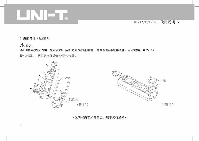
(图12)�
3.更换电池(见图13)
警告:
当LCD显示欠压“��”提示符时,应即时更换内置电池,否则会影响测量精度。电池规格:�6F22�9V
操作步骤: 类同更换保险丝管操作步骤。
*说明书内容如有变更,恕不另行通知*
(图13)�
保险丝�
电池

43
UT71A/B/C/D/E 使用说明书

44
UT71A/B/C/D/E 使用说明书

Model UT71A/B/C/D/EOPERATING MANUAL

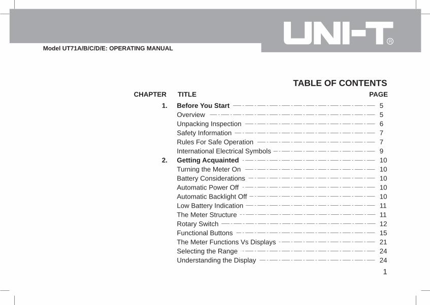
CHAPTER TITLE PAGE
Model UT71A/B/C/D/E: OPERATING MANUAL
1
TABLE OF CONTENTS
1.
2.
556779101010101011111215212424
Before You StartOverviewUnpacking InspectionSafety InformationRules For Safe OperationInternational Electrical SymbolsGetting AcquaintedTurning the Meter OnBattery ConsiderationsAutomatic Power OffAutomatic Backlight OffLow Battery IndicationThe Meter StructureRotary SwitchFunctional ButtonsThe Meter Functions Vs DisplaysSelecting the RangeUnderstanding the Display

2
Model UT71A/B/C/D/E: OPERATING MANUAL
29293030303234353739414344454747474848
3.
4.
CHAPTER TITLE PAGEAnalogue Bar GraphUsing MAX MINMaking MeasurementsIntroduction A. Measuring Voltages B. Measuring Currents C. Measuring Resistance D. Testing for Continuity E. Testing Diodes F. Measuring Capacitance G. Measuring Frequency / Duty Cycle H. Measuring Temperature I. 4~20mA loop current as % readout J. Power MeasurementUsing Stores, Recall and Send FeaturesIntroductionStoring and Clearing ReadingsRecalling Stored ReadingsUsing Send

3
Model UT71A/B/C/D/E: OPERATING MANUAL
5.
6.
7.
CHAPTER TITLE PAGE494949525253545555565758596060616364
Changing the Default SettingIntroductionSelecting Setup OptionsMaintenance A. General Service B. Replacing the Fuses C. Replacing the BatterySpecificationsSafety and CompliancesPhysical SpecificationsGeneral SpecificationsFeature SummaryBasic SpecificationsDetailed Accuracy Specifications A. DC Voltage B. AC Voltage C. DC Current D. AC Current
4
Model UT71A/B/C/D/E: OPERATING MANUAL
6565666667686969
CHAPTER TITLE PAGE E. Resistance F. Continuity Test G. Diode Test H. Capacitance I. Frequency J. Temperature Degrees Celsius Fahrenheit K. 4~20mA loop current L. Power Measurement

5
Model UT71A/B/C/D/E: OPERATING MANUAL
Chapter 1Before You Start
OverviewThis Operating Manual covers information on safety and cautions. Please read the relevant information carefully andobserve all the Warnings and Notes strictly.
WarningTo avoid electric shock or personal injury, read the"Safety Information" and "Rules for Safe Operation" carefullybefore using the Meter.
Digital Multimeter UT71A/B (hereafter referred to as "the Meter") is a 20000 counts and 4 1/2 digits with steadyoperations; Digital Multimeter UT71C/D/E (hereafter referred to as "the Meter") is a 40000 counts and 4 3/4 digitswith steady operations, fashionable structure and auto ranging instrument. They all not only can measure AC voltageand current, DC voltage and current, Resistance, Capacitance, Temperature, Frequency, Diodes, Continuity, 4~20mALoop, Max/Min, Relative Mode but also has Data Store, Data Recall, AC True RMS, AC+DC,Low Battery Display,Double Display Backl ight, Data Hold, Automatic Power Off and ful l over load protect ion.
UT71B/C/D/E has extra Temperature, 4~20mA Loop, Data Store and Data Recall feature; UT71E has extra PowerMeasurement feature.

6
Model UT71A/B/C/D/E: OPERATING MANUAL
Unpacking InspectionOpen the package case and take out the Meter. Check the items shown on Table 1-1 carefully to see any missingor damaged part:
Table 1-1. Unpacking Inspection
Item Description Qty
In the event you find any missing or damage, please contact your dealer immediately.
1
2
3
4
5
6
7
8
9
10
English Operating Manual
Test Lead
K-Type (nickel chromium ~ nickel silicon) Point Contact Temperature Probe (It is
only suitable for measuring temperature under 230 oC
Alligator Clip
Test Clip
USB interface cable
CD-ROM (Installation Guide & Computer Interface Software)
Carrying Bag
Power Adaptor (UT71E only)
9V Battery (NEDA 1604, 6F22, 006P)
1 piece
1 pair
1 piece
1 piece
1 pair
1 piece
1 piece
1 piece
1 piece
1 piece

7
Model UT71A/B/C/D/E: OPERATING MANUAL
Safety InformationThis Meter complies with the standards IEC61010 safetymeasurement requirement: in pollution degree 2,overvoltage category (CAT. III 1000V, CAT.IV 600V)and double insulation.
CAT. III: Distribution level, fixed installation, with smallertransient overvoltage than CAT. IVCAT.IV: Primary supply level, overhead lines, cablesystems etc.
Use the Meter only as specified in this operating manual,otherwise the protection provided by the Meter may beimpaired.
In this manual, a Warning identifies conditions andactions that may pose hazards to the user, or maydamage the Meter or the equipment under test.
A Note identifies the information that user should payattention to.
International electrical symbols used on the Meter andin this Operating Manual are explained on page 9.
Rules For Safe Operation
WarningTo avoid possible electric shock or personal injury,and to avoid possible damage to the Meter or to theequipment under test, adhere to the following rules:
Before using the Meter inspect the case. Do notuse the Meter if it is damaged or the case (or partof the case) is removed. Look for cracks or missingplastic. Pay attention to the insulation around theconnectors.Inspect the test leads for damaged insulation orexposed metal. Check the test leads for continuity. Replace damaged test leads with identical modelnumber or electrical specifications before using theMeter.Do not apply more than the rated voltage, as markedon the Meter, between the terminals or between anyterminal and grounding.The rotary switch should be placed in the rightposition and no any changeover of range shall bemade during measurement is conducted to preventdamage of the Meter.
l
l
l
l

8
Model UT71A/B/C/D/E: OPERATING MANUAL
l
l
l
l
l
l
l
l
l
l
l
ll
l
When the Meter working at an effective voltage over60V in DC or 30V rms in AC, special care should betaken for there is danger of electric shock.Use the proper terminals, function, and range foryour measurements.If the value to be measured is unknown, use themaximum measurement position.Do not use or store the Meter in an environment ofhigh temperature, humidity, explosive, inflammableand strong magnetic field. The performance of theMeter may deteriorate after dampened.When using the test leads, keep your fingers behindthe finger guards.Disconnect circuit power and discharge all high-voltage capacitors before testing resistance,continuity, diodes.Before measuring current, check the Meter's fusesand turn off power to the circuit before connectingthe Meter to the circuit.Replace the battery as soon as the battery indicator appears. With a low battery, the Meter mightproduce false readings that can lead to electricshock and personal injury.
When servicing the Meter, use only the same modelnumber or identical electrical specificationsreplacement parts.The internal circuit of the Meter shall not be alteredat will to avoid damage of the Meter and any accident.Soft cloth and mild detergent should be used toclean the surface of the Meter when servicing. Noabrasive and solvent should be used to prevent thesurface of the Meter from corrosion, damage andaccident.The Meter is suitable for indoor use.Turn the Meter off when it is not in use and take outthe battery when not using for a long time.Constantly check the battery as it may leak when ithas been using for some time, replace the batteryas soon as leaking appears. A leaking battery willdamage the Meter.

9
Model UT71A/B/C/D/E: OPERATING MANUAL
International Electrical SymbolsSymbols used on the Meter and in this manual are explained in Table1-2.
Table 1-2. International Electrical Symbols
AC or DC
DC Measurement
AC Measurement
Grounding
Double Insulated
Warning. Refer to the Operating Manual
Deficiency of Built-In Battery
Conforms to Standards of European Union

10
Model UT71A/B/C/D/E: OPERATING MANUAL
Chapter 2Getting Acquainted
Turning the Meter OnTo turn the Meter on, turn the rotary switch from OFFto any switch setting.
Battery ConsiderationsThe Meter uses one 9V Battery (NEDA 1604, 6F22,006P). The following paragraphs describe severaltechniques used to conserve battery power.
Automatic Power OffThe display blanks and the Meter goes into a "sleep"mode if you have not changed the rotary switch positionor pressed a button for a set period. While in Sleepmode, pressing the blue button or turning the rotaryswitch could turn the Meter on. The Meter then returnsto the display for the function selected with the rotaryswitch; all previously activated button features arediscarded.
Automatic Backlight OffPress LIGHT button to turn the backlight on and pressLIGHT again to turn it off. Press EXIT to exit the feature.
Press LIGHT to select the backlight level (low or high). In Setup menu (see Chapter 5), you could specify atime to automatically turn off the backlight (10 seconds,20 seconds, 30 seconds or OFF). If the period is setto OFF, the backlight feature is disabled.
The automatic power off is preset to 10 minutes. Fromthe Setup menu (see Chapter 5), you could specify atime (10 minutes, 20 minutes, 30 minutes or OFF). Ifyou set to OFF, the Meter retains on until you turn therotary switch to OFF or the battery becomes too weak.
11
Model UT71A/B/C/D/E: OPERATING MANUAL
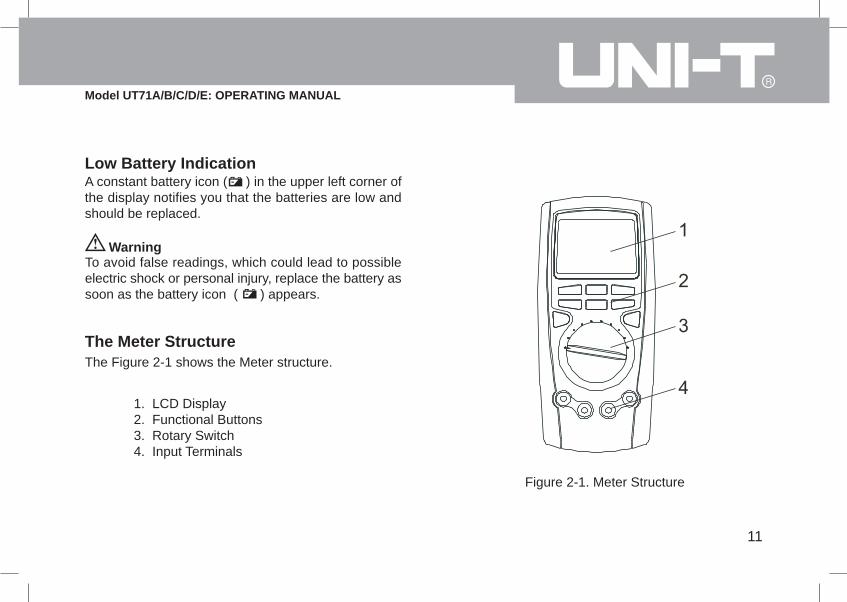
Low Battery IndicationA constant battery icon ( ) in the upper left corner ofthe display notifies you that the batteries are low andshould be replaced.
WarningTo avoid false readings, which could lead to possibleelectric shock or personal injury, replace the battery assoon as the battery icon ( ) appears.
The Meter StructureThe Figure 2-1 shows the Meter structure.
1. LCD Display2. Functional Buttons3. Rotary Switch4. Input Terminals
Figure 2-1. Meter Structure

12
Model UT71A/B/C/D/E: OPERATING MANUAL
Rotary SwitchTurn the Meter on by selecting any measurement function. The Meter presents a standard display for that function. The display may also be influenced by some of the choices made in Setup.
Use the blue button to select any rotary switch alternate function (labeled in blue letters).
When you turn the rotary switch from one function to another, a display for the new function appears. Button choicesmade in one function do not carry over into another function.
The Table 2-1 described each rotary switch position
13
Model UT71A/B/C/D/E: OPERATING MANUAL
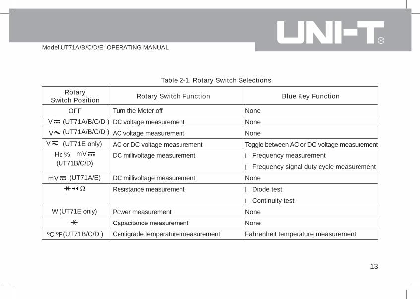
Table 2-1. Rotary Switch Selections
RotarySwitch Position Rotary Switch Function Blue Key Function
Turn the Meter off
DC voltage measurement
AC voltage measurement
AC or DC voltage measurement
DC millivoltage measurement
DC millivoltage measurement
Resistance measurement
Power measurement
Capacitance measurement
Centigrade temperature measurement
None
None
None
Toggle between AC or DC voltage measurement
Frequency measurement
Frequency signal duty cycle measurement
None
Diode test
Continuity test
None
None
Fahrenheit temperature measurement
OFF
V
Hz % mV
ºC ºF
l
l
V
V
l
l
mV
(UT71B/C/D)
W (UT71E only)
(UT71B/C/D )
(UT71A/B/C/D ) (UT71A/B/C/D )
(UT71E only)
(UT71A/E)

14
Model UT71A/B/C/D/E: OPERATING MANUAL
RotarySwitch Position Rotary Switch Function Blue Key Function
Centigrade temperature measurement
AC or DC current measurement (400µA ,4000µA)
AC or DC current measurement (40mA ,400mA)
AC or DC current measurement (10A)
Fahrenheit temperature measurement
Frequency measurement
Frequency signal duty cycle measurement
Toggle between AC or DC current
Toggle between AC or DC current
4~20mA loop current as % reading
Toggle between AC or DC current
mAµA
A
(4~20mA)%
l
l
l(UT71E only)ºC ºFHz %

15
Model UT71A/B/C/D/E: OPERATING MANUAL
Functional Buttons
The buttons activate features that augment the function selected with the rotary switch. The buttons are shownin Table 2-2.
STORE
RECALL
Press the button once to access the main feature (e.g. STORE).
To access the first additional feature of the button (e.g. RECALL), press and hold the button for over 1 second toaccess this additional feature. This additional feature appears right above or on the left hand side of the appropriatekeys.
To access the second additional feature of the button (e.g. ), press once the button again while the Meter hasalready entered the first additional feature (e.g. RECALL). The second additional feature appears on the right handside above the appropriate keys.
The RANGE and EXIT buttons has only one additional feature.

16
Model UT71A/B/C/D/E: OPERATING MANUAL
Table 2-2. Functional Buttons
Button Description Access Method
RANGE
SETUP
STORE
RECALL
Press the button once.
Press and hold the button while
turning on the Meter
Press and hold the button for more
than 1 second
Press the button
once.
Range feature:
Exit AUTO and enter MANUAL ranging. In MANUAL, select
next input range. EXIT to return to AUTO. AUTO is default.
Testing resistance signal from calibrator:
When testing resistance signal from calibrator, it is necessary
to press this button to change the maximum display to 4000
counts but the accuracy remains unchanged.
Setup feature:
Access Setup selections, the display shows "SET".
In the Setup mode, each press of SETUP button steps to
the next Selection
Store feature:
Store the current measurement value. Press EXIT to exit
the Store feature.

Model UT71A/B/C/D/E: OPERATING MANUAL
17
Table 2-2. Functional Buttons
Button Description Access Method
Press and hold the button for over 1
second
Press the button
once after entering Setup mode.
Press the button once.
Press and hold the button for over 1
second.
Press the button once after entering
Setup or Recall or Store mode.
Recall feature:
Recall the stored value. Press EXIT to exit the Recall feature.
Setup feature:
In Setup, press to select OFF at the selection of HIGH and
LOW
Hold feature:
Press HOLD to freeze the displayed value. Press EXIT to
release the display.
Peak Hold feature:
Press to access Peak Hold feature, the primary display
shows PEAK HOLD. Press EXIT to exit.
In Setup, each press to select the digit you want to edit.
In Recall, press to enable SEND feature
In Store, press to toggle between clearing all the stored
reading or start storing reading from the current index number.
STORE
RECALL
HOLD
Peak HOLD
l
l
l

Model UT71A/B/C/D/E: OPERATING MANUAL
Table 2-2. Functional Buttons
Button Description Access MethodPress the button once.
Press and hold the button for over 1
second.
Press the button once.
Press and hold
the button for over 1 second.
Press the button once after entering
SEND mode.
Press to exit certain button functions and the Meter will return
to the factory default setting.
Press to turn the backlight on. It is possible to toggle between
1st and the 2nd backlight level and Exit the feature by pressing
this button. After exiting the light feature, it is necessary to press
and hold the button for over 1 second to turn the backlight on
again.
Press to display max, min and average values.
Press EXIT to stop and return to current measurement mode.
Press to output the data, AUTO mode switch off. The primary
display shows "SEND".
Press EXIT to exit.
In Setup, each press to decrement an Option.
In Recall, each press to go back to the previous stored reading.
EXIT
LIGHT
MAXMIN
SEND
18

Model UT71A/B/C/D/E: OPERATING MANUAL
Press the button once.
Press and hold the button for over 1second.
In Store, each press to decrease a second on the storinginterval.Press EXIT to exitPress to enter relative mode, the primary display shows .The left secondary display shows the present measurementvalue. The right secondary display shows the stored value.The primary display shows the present measurement valueminus the stored value.Press EXIT to exit relative mode.In Setup, each press to increment an Option.In Recall, each press to recall the next stored reading.In Store, each press to increase a second on the storing interval.
Table 2-2. Functional Buttons
Button Description Access Method
MAXMIN
SEND
REL
19
SENDPress the button once.Press to output the data, AUTO mode switch off. The
primary display shows "SEND".Press EXIT to exit.(UT71A only)

Model UT71A/B/C/D/E: OPERATING MANUAL
Blue Button
Press the button once
Press the button once
AC+DCWhen it is at AC measurement mode, press the button to
display AC+DC True RMS value in the primary display and the
left secondary display "AC+DC".
Use the blue button to select any rotary switch alternate function
(labeled in blue letters).
Press and hold the Button while turning on the Meter to toggle
to 4000 counts for all functions.
It is faster when the Meter is at 4000 counts measurement
mode.
After the Meter is resuming from Automatic Power Off or turn
on and off again, the Meter will back to normal measurement
mode (40000 counts).
Table 2-2. Functional Buttons
Button Description Access Method
20
SENDPress the button
once after entering Setup mode.
Setup feature:
In Setup, press to select OFF at the selection of HIGH and LOW(UT71A only)
Yellow Button

21
Model UT71A/B/C/D/E: OPERATING MANUAL
The Meter Functions Vs DisplaysTable 2-3 shows the cross reference of function and display:
Table 2-3 Functions Vs Displays
Function Primary Display Right Secondary Display Left Secondary Display
DCV
ACV
DCmV
The tested DC voltage value
The tested AC voltage value
The tested DCmV value
The tested resistance value
The tested resistance value
The tested resistance value
The tested frequency value
The tested capacitance value
The tested ºC value
The tested ºF value
The tested DCµA value
No display
The tested frequency value:
45.00Hz~ 100.0kHz
No display
No display
No display
No display
No display
No display
No display
No display
No display
Full range: 4, 40, 400, 1000
Full range: 4, 40, 400, 1000
Full range 400
Full range: 400, 4, 40, 400, 4, 40
Full range value: 400
Full range 4
Full range: 40, 400, 4, 40, 400, 4, 40, 400
Full range: 40, 400, 4, 40, 400, 4, 40
1000
1832
Full range: 400, 4000
ºC
ºF
Hz
DCµA

22
Model UT71A/B/C/D/E: OPERATING MANUAL
Table 2-3 Functions Vs Displays
Function Primary Display Right Secondary Display Left Secondary Display
The tested ACµA value
The tested DCmA value
The tested ACmA value
The tested DC current value
The tested AC current value
The tested power value
Data recalled is on
The tested frequency value:
45.00Hz~10.00kHz
No display
The tested frequency value:
45.00Hz~10.00kHz
No display
The tested frequency value:
45.00Hz~10.00kHz
Apparent power value
Full range: 400, 4000
Full range: 40, 400
Full range: 400, 4000
Full range: 10
Full range: 10
Power factor value
ACµA
DCmA
ACmA
DCA
ACA
W
RCL

23
Model UT71A/B/C/D/E: OPERATING MANUAL
Table 2-3 Functions Vs Displays
Function Primary Display Right Secondary Display Left Secondary Display
The recalled value
The present measurement value
minus the stored value
The total number of stored value.
The stored value
Index number:
no.0001~no.0100 (For UT71A/B/C/E)
no.0001~no.9999 (For UT71D)
The present measurement value.
STO
MAX MIN
REL
Chapter 2 Getting Acquainted - Using MAX MIN

24
Model UT71A/B/C/D/E: OPERATING MANUAL
Selecting the RangePress RANGE to select either a fixed range or theautorange feature.
Autoranging (AUTO lighted in the display) always comeson initially when you select a new function. In autorange,the Meter selects the lowest input range possible,ensuring that the reading appears with the highestavailable resolution.
If AUTO is already on, press RANGE to enter MANUALranging in the present range. You can then select thenext manual range each time you press RANGE.Return to autoranging by press EXIT.
Note that there is no MANUAL ranging on REL feature.
Understanding the DisplayDisplay features are shown in Figure 2-2 and describedin Table 2-4.
Figure 2-2. Display Features

25
Model UT71A/B/C/D/E: OPERATING MANUAL
Table 2-4. Display Features
No. Symbol Meaning
1
2
3
4
5
6
MAX
MIN
No
ºC, ºF
SET
Maximum reading displayed.
Minimum reading displayed
The sequence of the reading.
Degrees Celsius (default) or Fahrenheit.
Indicates negative reading
The battery is low.
Warning: To avoid false readings, which could lead to possible electric shock
or personal injury, replace the battery as soon as the battery indicator appears.
Setup feature is on.

26
Model UT71A/B/C/D/E: OPERATING MANUAL
Table 2-4. Display Features
No. Symbol Meaning
7
8
9
TrueRMS
AC+DC
, k , M
Hz, kHz, MHz
mV, V
µA, mA, A
Indicator for True RMS value.
For DCV and DCA functions, reading represents the True RMS total of AC and
DC measurements
: Ohm. The unit of resistance.
k :Kilohm. 1 x 10³ or 1000 ohms
M :Megaohm. 1 x 10⁶ or 1,000,000 ohms
Hz : Hertz. The unit of frequency in cycles/second.
kHz: Kilohertz. 1 x 10³ or 1000 hertz
MHz: Megahertz, 1 x 10⁶ or 1,000,000 hertz.
V: Volts. The unit of voltage.
mV: Millivolt. 1 x 10⁻³ or 0.001 volts
A: Amperes (amps). The unit of current.
mA: Milliamp, 1 x 10⁻³ or 0.001 amperes.
µA:Microamp.1 x 10-6 or 0.000001 amperes.

27
Model UT71A/B/C/D/E: OPERATING MANUAL
Table 2-4. Display Features
No. Symbol Meaning
9
10
11
12
13
14
15
16
nF,µF,
mF
STO
RCL
LOW
HIGH
AUTO
SEND
Farad. The unit of capacitance
nF: Nanofarad. 1 x 10⁻⁹ or 0.000000001 farads.
µF:Microfarad.1 x 10-6 or 0.000001 farads.
mF: Millifarad. 1 x 10⁻³ or 0.001 farads.
Automatic power off feature is on
Continuity test
Data store is on
Data recall is on
The relative mode is on to display the present value minus the stored value.
The indicator for the lowest setup limit.
The indicator for the highest setup limit.
The Meter is in the auto range mode in which the Meter automatically selects the
range with the best resolution.
Data output is in progress

28
Model UT71A/B/C/D/E: OPERATING MANUAL
Table 2-4. Display Features
No. Symbol Meaning
17
18
19
20
21
22
23
24
25
26
HOLD
PEAK HOLD
%
OL
Analogue Bar Graph
Backlight feature is on
Data hold mode is active
Peak hold mode is active
Diode test
Frequency signal duty cycle.
4~20mA loop current as % reading
The input value is too large for the selected range.
Provides an analog indication of the present input, quick response.
Indicator of power factor.
Indicator of apparent power unit.
Indicator of power measurement
l
l
COS
VA
W

29
Model UT71A/B/C/D/E: OPERATING MANUAL
Analogue Bar GraphThe bar graph provides an analogue indication of themeasured input. For most measurement functions, thebar graph updates 10 times per second.
Using MAX MINThe MAX MIN mode stores minimum (MIN) andmaximum (MAX) input values. When the input goesbelow the stored minimum value or above the storedmaximum value, the Meter beeps and stores the newvalue.
Press MAX MIN to enter MAX MIN mode. The samplingtime is every 2 seconds. The maximum reading andMAX are shown on the left secondary display. Theminimum reading and MIN are shown on the rightsecondary display. The primary display shows thecurrent measurement reading.
Press MAX MIN the second time, the currentmeasurement reading is shown on the left secondarydisplay. The minimum reading and MIN are shown on
the right secondary display. The primary display showsthe maximum value.
Press MAX MIN the third time, the current measurementreading is shown on the left secondary display. Themaximum reading and MAX are shown on the rightsecondary display. The primary display shows theminimum value.
Each subsequent press of MAX MIN steps through theabove three modes.
To exit MAX MIN mode, press EXIT.
Press HOLD to stop the Meter updating reading.
MAX MIN mode can only be used under MANUALranging mode.

30
Model UT71A/B/C/D/E: OPERATING MANUAL
Chapter 3Making Measurement
IntroductionChapter 3 explains how to make measurements. Mostmeasurement functions can be selected by using therotary switch.
While letters or symbols identify primary functions; blueletters or symbols identify alternative functions. Pressthe BLUE button to access these alternate functions.
A. Measuring Voltages
WarningTo avoid harms to you or damages to the Meterfrom electric shock, please do not attempt tomeasure voltages higher than 1000V, althoughreadings may be obtained.To measure voltages, set up the Meter as Figure 3-1and do the following:
Figure 3-1. Voltages Measurement

31
Model UT71A/B/C/D/E: OPERATING MANUAL
Insert the red test lead into the V terminal and theblack test lead into the COM terminal.Set the rotary switch to or or ;Set the rotary switch to or or (UT71E).The default is DC voltage measurement, press BLUEbutton to switch to AC voltage measurement mode.Connect the test leads across with the object beingmeasured.The measured value shows on the display.AC measurement displays the True RMS value.DC measurement displays the effective value of sinewave (mean value response).
1.
2.
3.
4.
VmV
V
When a ACV function is selected, you can press theYellow Button to view the AC + DC True RMS valuein the primary display. To exit, please EXIT button.
The BLUE button cycles among , frequency andduty cycle.
mV
V mVV
NoteWhen measuring voltage, the Meter acts around a10M ( and ) or 2.5G ( ) impedance inparallel with the circuit. This loading effect can causemeasurement errors in high impedance circuits. Inmost cases, the error is negligible (0.1% or less) ifthe circuit impedance is 10k or less.Special care should be taken when measuring highvoltage.When voltage measurement has been completed,disconnect the connection between the testing leadsand the circuit under test and remove testing leadsaway from the input terminals of the Meter.
l
l
l
mV
V

32
Model UT71A/B/C/D/E: OPERATING MANUAL
B. Measuring Currents
WarningIf the fuse burns out during measurement, the Metermay be damaged or the operator himself may be hurt.
To avoid possible damage to the Meter or to theequipment under test, check the Meter's fuses beforemeasuring current. Use proper terminals, function,and range for the measurement. Never place thetesting leads in parallel with any circuit or componentwhen the leads are plugged into the current terminals.
Figure 3-2. Currents Measurement
To measure AC or DC current, set up the Meter asFigure 3-2 and proceed as follows:

33
Model UT71A/B/C/D/E: OPERATING MANUAL
Turn off power to the circuit. Discharge all high-voltage capacitors.Insert the red test lead into the mAµA or A terminaland black test lead into the COM terminal.If you are using the A terminal, set the rotary switchto . If you are using mAµA terminal, set therotary switch to for currents below 40000µA(UT71A is 20000µA), or for current above40000µA (UT71B is 20000µA).DC measurement is default, press blue button toselect AC measurement.tOpen the circuit path to be tested. Touch the redtesting leads to the more positive side of the break;touch the black probe to the more negative side ofthe bread. Reversing the leads will produce anegative reading, but will not damage the Meter.Turn on power to the circuit; then read the display.AC measurement displays the True RMS value.DC measurement displays the effective value of sinewave (mean value response)Turn off power to the circuit and discharge all high-voltage capacitors. Remove the Meter and restore
1.
2.
3.
4.
5.
6.
7.
AµA
mA
When a ACA function is selected, you can press theYellow Button to view the AC + DC True RMS valuein the primary display. To exit, please EXIT button.
NoteIf the value to be measured is unknown, use themaximum measurement position and reduce therange step by step until a satisfactory reading isobtained.When the measured current is 5A, continuousmeasurement is allowed.When the measured current is between 5A-10A,continuous measurement 10 seconds and intervalmore than 15 minutes.When current measurement has been completed,disconnect the connection between the testing leadsand the circuit under test and remove testing leadsaway from the input terminals of the Meter.
l
l
l
l

34
Model UT71A/B/C/D/E: OPERATING MANUAL
C. Measuring Resistance
Figure 3-3. Resistance Measurement
WarningTo avoid harms to you, please do not attempt to inputvoltage higher than 60V DC or 30V rms AC.
To avoid possible damages to the Meter or to thedevices under test, disconnect circuit power anddischarge all the high-voltage capacitors beforemeasuring resistance.To measure resistance, set up the Meter as shown inFigure 3-3 and follow the following procedure:
Insert the red test lead into the terminal and theblack test lead into the COM terminal.Set the rotary switch to ; press BLUE buttonto select measurement mode.Connect the test leads across with the object beingmeasured.The measured value shows on the display.
1.
2.
3.
The BLUE button cycles among resistance, continuity,and diode.

35
Model UT71A/B/C/D/E: OPERATING MANUAL
D. Testing for Continuity
WarningTo avoid harms to you, please do not attempt to inputvoltage higher than 60V DC or 30V rms AC.
To avoid possible damages to the Meter or to thedevices under test, disconnect circuit power anddischarge all the high-voltage capacitors beforemeasuring continuity.
To test for continuity, set up the Meter as Figure 3-4and do the following:
Insert the red test lead into the terminal and theblack test lead into the COM terminal.Set the rotary switch to ; press BLUE buttonto select measurement mode and connet thetest leads across with the object being tested.The beeper comes on continuously for openconditions, that is test resistance 50 .
1.
2.
3.
The BLUE button cycles among resistance, continuity,and diode.
NoteWhen measuring low resistance, the test leads canadd 0.1 to 0.2 of error to resistance measurement.To test the leads, touch the probe tips together andread the resistance of the leads. If necessary, youcan press REL to automatically subtract this value.For high-resistance measurement (>1M ), it is normaltaking several seconds to obtain a stable reading.In order to obtain precision readings, use the testlead as short as possible.The LCD displays OL indicating open-circuit or thetested resistor value is higher than the maximumrange of the Meter.When testing the resistance signal from the calibrator,it is necessary to press and hold the RANGE whileturning on the Meter to change the maximum displayto 4000 counts but the accuracy remains unchanged.When resistance measurement has been completed,disconnect the connection between the testing leadsand the circuit under test and remove testing leadsaway from the input terminals.
l
l
l
l
l

36
Model UT71A/B/C/D/E: OPERATING MANUAL
Figure 3-4. Continuity Test
NoteOpen circuit voltage around -1.2V and range is 400measurement range.When continuity testing has been completed,disconnect the connection between the testing leadsand the circuit under test and remove the test leadsaway from the input terminals.
l
l

37
Model UT71A/B/C/D/E: OPERATING MANUAL
E. Testing Diodes
Figure 3-5. Diode Test
WarningTo avoid harms to you, please do not attempt to inputvoltages higher than 60V DC or 30V rms AC.
To avoid damages to the Meter or to the devices undertest, disconnect circuit power and discharge all thehigh-voltage capacitors before testing diodes.
Use the diode test to check diodes, transistors, andother semiconductor devices. The diode test sends acurrent through the semicondutor junction, then measurethe voltage drop across the junction. A good siliconjunction drops between 0.5V and 0.8V
To test the diode out of a circuit, set up the Meter asFigure 3-5 and proceed as follows:
Insert the red test lead into the terminal and theblack test lead into the COM terminal.Set the rotary switch to ; and press BLUEbutton to select measurement mode.
1.
2.

38
Model UT71A/B/C/D/E: OPERATING MANUAL
For forward voltage drop readings on anysemiconductor component, place the red test lead onthe component's anode and place the black test leadon the component's cathode. The red test lead polarityis "+" while the black test lead polarity is "- ".The measured value shows on the display.
3.
The BLUE button cycles among resistance, continuity,and diode.
NoteIn a circuit, a good diode should still produce aforward voltage drop reading of 0.5V to 0.8V; however,the reverse voltage drop reading can vary dependingon the resistance of other pathways between theprobe tips.Connect the test leads to the proper terminals assaid above to avoid error display.The LCD will display OL indicating either open circuitor wrong polarity connection.The unit of diode is volt (V), displaying the positive-connection voltage-drop value.Open c i rcui t vol tage approximate 2.8V.
l
l
l
l
l
l When diode testing has been completed, disconnectthe connection between the testing leads and thecircuit under test and remove the test leads awayfrom the input terminals.

39
Model UT71A/B/C/D/E: OPERATING MANUAL
F. Measuring Capacitance
Figure 3-6. Capacitance Measurement
WarningTo ensure accuracy, the Meter inside is dischargedagainst the tested capacitor. "DIS.C" will be shownon the display when it is under discharging, thisprocess will be quite slow.
To avoid damage to the Meter or to the equipmentunder test, disconnect circuit power and dischargeall high-voltage capacitors before measuringcapacitance.
Use the DC Voltage function to confirm that the capacitoris discharged.
To measure capacitance, set up the Meter as shownin Figure 3-6 and proceed as follows:
Insert the red test lead into the terminal andthe black test lead into the COM terminal.
1.

40
Model UT71A/B/C/D/E: OPERATING MANUAL
Set the rotary switch to measurement mode,the Meter may display a fixed reading which is ainternal distributed capacitor value. For testing lessthan 10nF capacitor, the tested value must subtractthe internal distributed capacitor value to maintainthe accuracy.To improve the measurement accuracy of small valuecapacitors (less than 10nF), press REL with thetest leads open to subtract the residual capacitanceof the Meter and leads.It is recommended to use test clip to carry outmeasurement to reduce the effect of internaldistributed capacitor.
2.
3.
NoteThe LCD displays OL indicating the tested capacitoris shorted or it exceeds the maximum range.Capacitors larger than 400µF take longer time. Theanalogue bar graph shows the time left beforefinishing the measurement.
l
l
When capacitance measurement has beencompleted, disconnect the connection between thetesting leads and the circuit under test and removethe test leads away from the input terminals of theMeter.
l

G. Measuring Frequency / Duty Cycle
Figure 3-7. Frequency / Duty Cycle Measurement
41
Model UT71A/B/C/D/E: OPERATING MANUAL
WarningTo avoid harms to you, please do not attempt to inputvoltage higher than 30V rms.
To measure frequency and duty cycle, connect theMeter as Figure 3-7 and do the following:
Insert the red test lead into the Hz terminal andthe black test lead into the COM terminal.Set the rotary switch to (UT71A), (UT71B/C/D)or (UT71E) and press BLUE button to selectthe Hz measurement mode for frequencymeasurement or % for duty cycle measurement.The BLUE button cycles among , frequencyand duty cycle for UT71C and UT71E.Connect the test leads across with the object beingmeasured.The measured value shows on the primary display.
1.
2.
3.
mV
ºC ºF
42
Model UT71A/B/C/D/E: OPERATING MANUAL
NoteThe requirement of Input amplitude "a" is as follows:When 10Hz~40MHz: 200 mV a 30Vrms;> 40MHz: Un-specifiedWhen Hz measurement has been completed,disconnect the connection between the testing leadsand the circuit under test and remove the test leadsaway from the input terminals.
l
l

43
Model UT71A/B/C/D/E: OPERATING MANUAL
H. Measuring Temperature
WarningTo avoid harms to you, please do not attempt toinput voltages higher than 60V DC or 30V rms AC.
Set the rotary switch to ºC ºF, the display shows OL.Short circuit the test leads to show the roomtemperature. The Meter is default to Celsius ºCdegree unit, you can change units by press the BLUEbutton once you have selected the temperaturefunction.Insert the point contact temperature probe into theMeter as figure 10.Place the temperature probe to the object beingmeasured.The measured value shows on the display afterseveral seconds.
1.
2.
3.
Figure 3-8. Temperature Measurement
ºC ºF
To measure temperature, set up the Meter as shownin Figure 3-8 and proceed the following.

44
Model UT71A/B/C/D/E: OPERATING MANUAL
The rest procedure, please follow B. MeasuringCurrent: DC current measurement (Figure 3-2).When the readings obtained is:
2.
3.
Set the rotary switch to , and press BLUEbutton to select (4~20mA)% feature.
1.
NotePlace the Meter in an environment of 18ºC~23ºCotherwise false reading may be obtained especiallyin testing low temperature.The included point contact temperature probe canonly be used with temperature 230ºC below.When temperature measurement has beencompleted, remove the temperature probe away fromthe multi-purpose socket, and remove the multi-purpose socket away from the Meter.
l
l
l
< 4mA, the primary display shows LOl4mA, the primary display shows 0%. ….20mA, the primary display shows 100%> 20mA, the primary display shows HI
ll
l
I. 4~20 mA loop current as % readout(UT71B/C/D/E)
It shows the mA measured value or output level in %,in a 4-20mA scale
To use 4~20mA Loop feature, connect the Meter asfollows:
mA
45
Model UT71A/B/C/D/E: OPERATING MANUAL
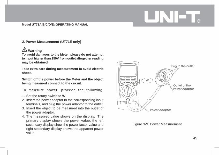
J. Power Measurement (UT71E only)
WarningTo avoid damages to the Meter, please do not attemptto input higher than 250V from outlet altogether readingmay be obtained.
Take extra care during measurement to avoid electricshock.
Switch off the power before the Meter and the objectbeing measured connect to the circuit.
Set the rotary switch to W.Insert the power adaptor to the corresponding inputterminals, and plug the power adaptor to the outlet.Insert the object to be measured into the outlet ofthe power adaptor.The measured value shows on the display. Theprimary display shows the power value, the leftsecondary display show the power factor value andright secondary display shows the apparent powervalue.
1.2.
3.
4.
Figure 3-9. Power Measurement
To measure power, proceed the fol lowing:

46
Model UT71A/B/C/D/E: OPERATING MANUAL
NoteThe current of the object being measured must >10A.
5A continuous measurement is allowed.5A~10A, only 10 seconds continuous measurementis allowed and the interval between eachmeasurement must be greater than 15 minutes.When power measurement has been completed,first switch off the power, then disconnect theconnection between the adaptor and the outlet.
l
l

47
Model UT71A/B/C/D/E: OPERATING MANUAL
Press STORE once, STO and "no.xxxx" appears toconfirm the operation and the left secondary displayshows the current measurement reading. Pressto toggle between clearing the stored readings andstart from the first readings or start from the last storedreading. Right secondary display shows the originalnumber of records.Press STORE the second time, STO appears. Theleft secondary display shows the storing time intervalin second, it is preset to zero. To change the intervalin second by pressing + or - button. The interval can
l
l
l
l
l
l
be as high as 255 seconds or as low as 0 second.Press and hold STORE to access the quick setting.Press STORE the third time, STO and no appears. The left secondary display shows the index numberincrease one. The right secondary display showsthe value of the corresponding index number, theprimary display shows the current measurementreading.If there is not set time to store the reading, each pressof STORE to store one reading. An index numberincrease one.The maximum number of stored reading is 100 (forUT71C and UT71E) and 9999 (for UT71D). Whenthe stored readings memory is full, the Meter will stopstoring data.To exit, press EXIT.Automatic power off feature will be disabled afterentering this mode.
Chapter 4Using Store, Recall & Send Features
IntroductionChapter 4 shows you how to use stores, recall andcommunication features available on the Meter
Storing and Clearing ReadingsTo store readings, proceed as follows:

48
Model UT71A/B/C/D/E: OPERATING MANUAL
Press RECALL to recall the stored value and RCLappears to confirm the operation.The left secondary display shows the index number"no.xxxx".The primary display shows the corresponding recalleddata.The right secondary display shows the total numberof the stored data.Press button to enable the SEND feature to exportthe data to the computer via USB. The softwareshows the data storing time and also the data value. After the data transferring is completed, the SENDfeature will be disabled automatically.Press + or - button to view additional stored reading.Press and hold RECALL to access quick recalling.Press EXIT to exit recalling.
l
l
l
l
l
l
l
Recalling Stored ReadingsUse the following procedure to recall the stored reading:
Using SendWhen using a Send feature, please refer to the InstallationGuide of the included CD-ROM.

49
Model UT71A/B/C/D/E: OPERATING MANUAL
Chapter 5Changing the Default Setting
IntroductionThe Meter allows you to change the default operating configuration of the Meter by changing setup options madeat the factory.
These settings are stored and can be changed in the Setup mode using the procedure described in this chapter.
Selecting Setup OptionsTo enter the Setup mode, turn the Meter on and press and hold SETUP button for over 1 second. It is recommendedto change the default setting only when the Meter is at DCV measurement mode.
In the Setup mode, each press of SETUP button steps to the next Selection. Each press of - or + button decrementor increment an Option.
Each Setup Selection and Option appears in the primary display in the sequence shown in Table 5-1.

50
Model UT71A/B/C/D/E: OPERATING MANUAL
Table 5-1. Setup Selections
Selection Option Factory Default Description
Max. 40000. Press to select OFF
Press to select the digit you want to edit
Max. 40000. Press to select OFF
Press to select the digit you want to edit
10
20
30
OFF
1
OFF
10
20
30
OFF
OFF
OFF
10 mins
1
10
Over the upper limits, beeps not
continuously.
Over the lower limits, beeps not continuously.
10 mins power off
20 mins power off
30 mins power off
Power off feature is disabled
Beeps continuously and icon lights on
No beep, icon flashes
Backlight turn off in 10 seconds
Backlight turn off in 20 seconds
Backlight turn off in 30 seconds
Disable backlight feature.
HIGH
LOW

51
Model UT71A/B/C/D/E: OPERATING MANUAL
Table 5-1. Setup Selections
Selection Option Factory Default Description
Zero is in the left hand side.
Zero is in the center
Zero is in the
centerIt can only apply to DCV, DCI and °C/°F functions.
Analogue
Bar
Graph
Saving Setup OptionsAt each setup Option, store your choice and exit setup by press EXIT, advance to the next Option by press +.To exit the Setup mode without saving the present Option, press Setup.
0 1 2 3 4
-4 -2 0 2 4

52
Model UT71A/B/C/D/E: OPERATING MANUAL
WarningDo not attempt to repair or service your Meter unless you are qualified to do so and have the relevant calibration,performance test, and service information.
Periodically wipe the case with a damp cloth and mild detergent. Do not use abrasives or solvents.To clean the terminals with cotton bar with detergent, as dirt or moisture in the terminals can affect readings.Turn the Meter to OFF when it is not in use.Take out the battery when it is not using for a long time.Do not use or store the Meter in a place of humidity, high temperature, explosive, inflammable and strong magneticfield.
lllll
Chapter 6Maintenance
This chapter provides basic maintenance information including battery and fuse replacement instruction.
A. General Service

53
Model UT71A/B/C/D/E: OPERATING MANUAL
WarningTo avoid electrical shock or arc blast, or personalinjury or damage to the Meter, use specified fusesONLY in accordance with the following procedure.
Turn the rotary switch to OFF and remove allconnections from the terminals.Remove the 5 screws from the case bottom.Remove the fuse by gently prying one end loose,then take out the fuse from its bracket.Install ONLY replacement fuses with the identicaltype and specification as follows and make sure thefuse is fixed firmly in the bracket.Fuse 1: 0.5A, 250V, fast type fuse, 5x×20mmFuse 2: 10A, 250V, fast type fuse, 5x×20mmRejoin the case bottom and case top, and install the5 screws.
l
ll
l
l
B. Replacing the Fuses
Figure 6-1. Fuse Replacement
Follow Figure 6-1 and proceed as follows to replacethe Meter's fuse:
Replacement of the fuses is seldom required. Burningof a fuse always results from improper operation.
54
Model UT71A/B/C/D/E: OPERATING MANUAL
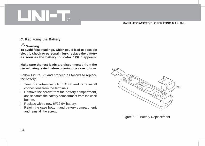
WarningTo avoid false readings, which could lead to possibleelectric shock or personal injury, replace the batteryas soon as the battery indicator " " appears.
Make sure the test leads are disconnected from thecircuit being tested before opening the case bottom.
Turn the rotary switch to OFF and remove allconnections from the terminals.Remove the screw from the battery compartment,and separate the battery compartment from the casebottom.Replace with a new 6F22 9V battery.Rejoin the case bottom and battery compartment,and reinstall the screw.
l
l
ll
C. Replacing the Battery
Figure 6-2. Battery Replacement
Follow Figure 6-2 and proceed as follows to replacethe battery:
55
Model UT71A/B/C/D/E: OPERATING MANUAL
Chapter 7Specifications
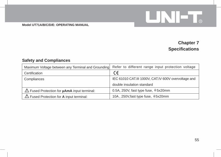
Safety and Compliances
Maximum Voltage between any Terminal and Grounding
Certification
Compliances
Fused Protection for µAmA input terminal:
Fused Protection for A input terminal:
Refer to different range input protection voltage
IEC 61010 CAT.III 1000V, CAT.IV 600V overvoltage and
double insulation standard
0.5A, 250V, fast type fuse, 5x20mm
10A , 250V,fast type fuse, 5x20mm

56
Model UT71A/B/C/D/E: OPERATING MANUAL
l
l
Physical Specifications
Display (LCD)
Operating Temperature
Storage Temperature
Relative Humidity
Battery Type
Electromagnetic Compatibility
Dimensions (H x W x L)
Weight
Digital: 40000 counts on primary display; updates 2-3
times / second.
4000 counts on two secondary displays.
Analog: 40 segments; updates 10 times / second.
0ºC~40ºC (32ºF~104ºF)
-10ºC~50ºC (14ºF~122ºF)
75% @ 0ºC~30ºCæ below;
50% @ 30ºC~40ºC:
9V NEDA 1604 or 6F22 or 006P.
In a radio field of 1 V/m below:
Overall Accuracy = Specified Accuracy + 5% of Range
In a radio field of 1 V/m above:
No assigned accuracy is specified.
177 x 85 x 40mm.
Approx.340g (including battery)
57
Model UT71A/B/C/D/E: OPERATING MANUAL
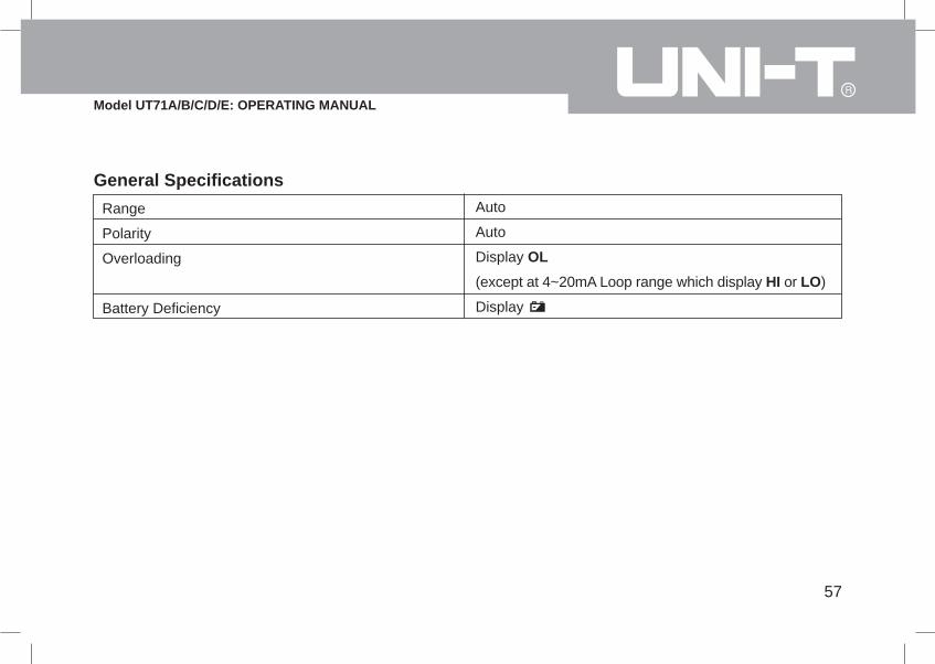
General SpecificationsRange
Polarity
Overloading
Battery Deficiency
Auto
Auto
Display OL
(except at 4~20mA Loop range which display HI or LO)
Display

58
Model UT71A/B/C/D/E: OPERATING MANUAL
Feature Summary
Tri Digital Displays
Analogue Bar Graph
Backlight with 2 brightness levels
Autorange
AC+DC True RMS, AC RMS
Data Hold
Continuity
Bar Graph
Duty Cycle
MAX MIN Mode
Battery Access Door
Primary: 40,000 counts
Left Secondary: 4000 counts
Right Secondary: 4000 counts
Bar Graph: 40 segments, updates 10 times / second
Bright backlight for clear readings in poorly lighted areas.
The Meter automatically selects best range
Choices for AC only or AC+DC readings
Holds readings on display
Beeper sounds for resistance readings below threshold.
40 segments
Measure signal on or off time in %.
Record maximum and minimum
Battery replaceable.

59
Model UT71A/B/C/D/E: OPERATING MANUAL
Basic Specifications
DC Voltage
AC Voltage, True RMS
Basic Accuracy
DC Current
AC Current, True RMS
Resistance
Capacitance
Frequency
Temperature
STORE Readings
0 to 1000V
0 to 1000V, 100kHz bandwidth
DC Voltage: 0.025%
AC Voltage: 0.4%
0 to 10A (5~10A for 10 seconds, interval 15 minutes)
0 to 10A (5~10A for 10 seconds, interval 15 minutes)
0 to 40M (UT71A/B is 0 to 20M )
0 to 40mF(UT71A/B is 0 to 20mF)
0~400MHz (UT71A/B is 0 to 200MHz)
-40ºC~1000ºC (-40ºF~1832ºF)(UT71B/C)
Up to 100 readings for UT71C and UT71E or 9999
readings for UT71D may be saved by the user in a
memory. These readings may be viewed by using Recall
feature.
Function Ranges / Description
60
Model UT71A/B/C/D/E: OPERATING MANUAL
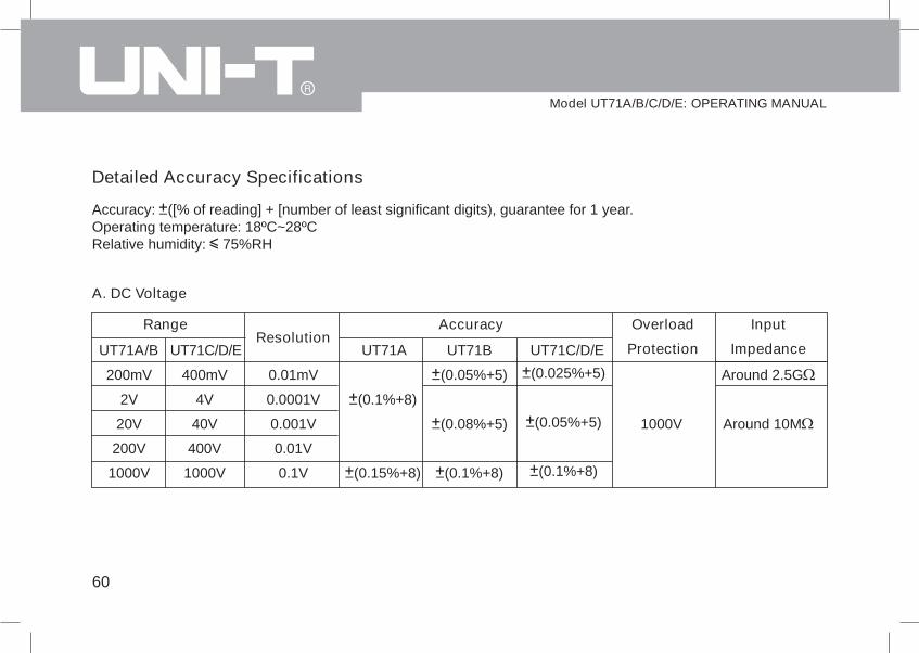
A. DC Voltage
Range Accuracy Overload
Protection
1000V
Input
Impedance
Around 2.5G
Around 10M
(0.025%+5)
(0.05%+5)
(0.1%+8)
UT71A/B
200mV
2V
20V
200V
1000V
400mV
4V
40V
400V
1000V
UT71C/D/EResolution
UT71A UT71C/D/E
(0.1%+8)
(0.15%+8)
(0.05%+5)
(0.08%+5)
(0.1%+8)
UT71B
Detailed Accuracy Specifications
Accuracy: ([% of reading] + [number of least significant digits), guarantee for 1 year.Operating temperature: 18ºC~28ºCRelative humidity: 75%RH
0.01mV
0.0001V
0.001V
0.01V
0.1V

61
Model UT71A/B/C/D/E: OPERATING MANUAL
RangeResolution
4V
40V
400V
1000V
BandwidthAccuracy
UT71C/D/EUT71C/D/EUT71A/B2V
20V
200V
1000V
UT71A UT71B
B. AC Voltage (AC+DC measurement is available)
0.0001V
0.001V
0.01V
0.1V
45Hz~1kHz1kHz~10kHz
10kHz~100kHz45Hz~1kHz1kHz~10kHz
10kHz~100kHz45Hz~1kHz1kHz~10kHz
10kHz~100kHz45Hz~1kHz1kHz~5kHz
5kHz~10kHz
(0.4%+30)(3%+30)(6%+30)
(0.4%+30)(3%+30)(6%+30)
(0.4%+30)(5%+30)
Not Specified(1%+30)(5%+30)
(10%+30)
(0.8%+40)(3%+40)(7%+40)
(0.8%+40)(3%+40)(7%+40)
(0.8%+40)(5%+40)
Not Specified(1.5%+40)
(0.6%+40)(3%+40)(7%+40)
(0.6%+40)(3%+40)(7%+40)
(0.6%+40)(5%+40)
Not Specified(1.2%+40)
(6%+40)(10%+40)
62
Model UT71A/B/C/D/E: OPERATING MANUAL
Remarks:lll
Input Impedance: Approx 10M .Overload Protection: 1000V.Display:a) True rms are valid from 10% of range to 100% of rangeb) AC crest factor can be up to 3.0 except 1000V where it is 1.5.c) A residual reading of 80 digits with test leads shorted, will not affect stated accuracy.d) When frequency is lower than 100kHz, the accuracy guarantee range 10%-100%.e) When making AC+DC measurment, the accuray need to add (1%+ 35 digits) of reading based on the above table.

63
Model UT71A/B/C/D/E: OPERATING MANUAL
C. DC Current
RangeResolution
AccuracyOverload Protection
400µA
4000µA
40mA
400mA
10A
(0.1%+15)
(0.15%+15)
(0.5%+30)
0.5A, 250V,
fast type fuse,
5x20mm
10A, 250V, fast type fuse,
5x20mm
Remarks:
ll
When the measured current is 5A, continuous measurement is allowed.When the measured current is between 5A-10A, continuous measurement 10 seconds and interval more than15 minutes.
At 10A range:
UT71C/D/E UT71C/D/E
200µA
2000µA
20mA
200mA
10A
(0.2%+20)
(0.8%+30)
(0.15%+20)
(0.7%+30)
UT71A/B UT71BUT71A
0.01µA
0.1µA
0.001mA
0.01mA
0.001A

64
Model UT71A/B/C/D/E: OPERATING MANUAL
RangeResolution
400µA
4000µA
40mA
400mA
10A
BandwidthAccuracy Overload
ProtectionUT71C/D/E UT71C/D/EUT71A/B
200µA2000µA20mA
200mA10A
UT71A UT71B
D. AC Current (AC+DC measurement is available)
0.01µA
0.1µA
0.001mA
0.01mA
0.001A
45Hz~1kHz
1kHz~10kHz
45Hz~1kHz
1kHz~10kHz
(0.7%+15)
(1%+40)
(1.5%+20)
(5%+40)
0.5A, 250V,
fast type fuse,
5x20mm
10A, 250V, fast type
fuse, 5x20mm
Remarks:l
l
Display:a)True rms are valid from 10% of range to 100% of rangeb) AC crest factor can be up to 3.0.c) A residual reading of 80 digits with test leads shorted, will not affect stated accuracy.d) When frequency is lower than 100kHz, the accuracy guarantee range 10%-100%.e) When making AC+DC measurment, the accuray need to add (1%+ 35 digits) of reading based on the above table.At 10A range:a) When the measured current is 5A, continuous measurement is allowed.b) When the measured current is between 5A-10A, continuous measurement 10 seconds and interval more than 15 minutes.
(1%+15)(2%+40)
(2%+20)(6%+40)
(0.8%+15)(1.5%+40)
(2%+20)(6%+40)

65
Model UT71A/B/C/D/E: OPERATING MANUAL
RangeResolution
Accuracy
400
4k40k
400k4M
40M
Overload
ProtectionUT71C/D/EUT71BUT71AUT71A/B
200
2k20k
200k2M
20M
UT71C/D/E
Range Resolution Overload Protection
Remarks:lll
Open circuit voltage approximate -1.2V.The buzzer does not sound when the test resistance is > 60 .The beeper comes on continuously for open conditions, that is test resistance is 40 .
E. Resistance
0.01
0.0001k0.001k0.01k
0.0001M0.001M
(0.3%+8)+test leadsshort circuit value
(0.3%+8)
(0.5%+20)(1%+40)
(1.5%+40)
1000V
F. Continuity Test
0.01 1000V
(0.5%+20)+test leadsshort circuit value
(0.5%+20)
(1%+20)(1%+40)
(1.5%+40)
(0.4%+20)+test leadsshort circuit value
(0.4%+20)
(0.8%+20)(1%+40)
(1.5%+40)
short circuit value

66
Model UT71A/B/C/D/E: OPERATING MANUAL
Range Resolution Overload Protection
Remarks:ll
Open circuit voltage approximate 2.8V.A good silicon junction drops between 0.5V and 0.8V.
H. Capacitance
RangeResolution
Overload
Protection
40nF
400nF
4µF
40µF
400µF
4mF
40mF
1 0 0 0 V
(1%+20)+capacitance value ofopen circuit test leads
(1%+20)
(1.2%+20)
(5%+20)
Not specified
Accuracy
UT71C/D/EUT71BUT71C/D/EUT71A/B
20nF
200nF
2µF
20µF
200µF
2mF
20mF
(1.5%+20)+capacitance value ofopen circuit test leads
(1.5%+20)
(1.5%+40)
(5%+40)
Not specified
(1.2%+20)+capacitance value ofopen circuit test leads
(1.2%+20)
(1.2%+40)
(1.5%+40)
(5%+40)
Not specified
UT71A
G. Diode Test
0.0001V 1000V
0.001nF
0.01nF
0.0001µF
0.001µF
0.01µF
0.0001mF
0.001 mF

67
Model UT71A/B/C/D/E: OPERATING MANUAL
Remarks:l Input amplitude "a" as follows; (DC electric level is zero)
When 10Hz~40MHz : 200mV a 30Vrms;When > 40MHz : Not specified
I. Frequency
RangeResolution
AccuracyOverload Protection
40Hz
400Hz
4kHz
40kHz
400kHz
4MHz
40MHz
400MHz
1 0 0 0 V(0.01%+8)
Not Specified
UT71C/D/EUT71A/BUT71C/D/EUT71A/B
20Hz
200Hz
2kHz
20kHz
200kHz
2MHz
20MHz
200MHz
(0.1%+15)
Not Specified
0.001Hz
0.01Hz
0.0001kHz
0.001kHz
0.01kHz
0.0001MHz
0.001MHz
0.01MHz

68
Model UT71A/B/C/D/E: OPERATING MANUAL
J. Temperature (UT71B/C/D/E)
Range Resolution Accuracy Overload Protection
1 0 0 0 V(3%+30)
(1%+30)
2.5%0.1ºC
-40ºF~32ºF
32ºF~752ºF
752ºF~1832ºF
(4%+50)
(1.5%+50)
3%
Degrees Celsius
0.1ºF
Remarks:l Included is a K-Type (nickel chromium ~ nickel silicon) point contact temperature probe which could only measure
temperature below 230ºC. If you want to measure temperature higher than 230ºC, you must use the rod contacttemperature probe.
-40ºC~40ºC
40ºC~400ºC
400ºC~1000ºC
Range Resolution Accuracy Overload Protection
1 0 0 0 V
Fahrenheit

69
Model UT71A/B/C/D/E: OPERATING MANUAL
K. 4~20 mA loop current (UT71B/C/D/E)Range Resolution Accuracy Overload Protection
(4~20mA)% 0.5A, 250V, fast type fuse, 5x20mm(1%+50)0.01%
Remarks:
lll
< 4mA, the primary display shows LO4mA, the primary display shows 0% .... ; 20mA, the primary display shows 100%> 20mA, the primary display shows HI
** END **
When the readings obtained is:
L. Power Measurement (UT71E only)Range Resolution Accuracy Current Overload Protection
2500W
1000V
0 . 1 W10A, 250V, fast type fuse, 5x20mm
Voltage Overload Protection
POWER
VA POWER
Cos POWER
2500W 1W
(2%+10)
(1%+10)
(2%+10)
Remarks:lll
Power factor input range: 0.000~1.000Voltage input impedance: around 10M .Voltage input range: AC50~250V
0 ~ 1 0.001W

70
Model UT71A/B/C/D/E: OPERATING MANUAL