pne 1119 pre-gondola 2
TRANSCRIPT

8/8/2019 pne 1119 Pre-Gondola 2
http://slidepdf.com/reader/full/pne-1119-pre-gondola-2 1/56
piqE - 1119
AV
KA
~k f~tc\x~Ib~ c iv l , ,ndusirial and scientific uses for nuclear explosives
UN ITED STATES, ARMY CORPS OF ENGINEERS
iORT PECK RESERVOIR PROJECTMONTANA
PRE,,GONDOLAKPre-Gondola 0
AIRBORNE LIDAR OBSERVATIONSReproduced by
NATIONAL TECHNICALINFORMATION SERVICED D CSonnqlueld. Va 221l1rir
R. T. H. Collis, John Oblanas ~
(V ;1 tanford Research Institute 2 9*~ ~. Acrophysics Laboratory
Menlo Park, California
U. S. Army Engineer Nuc-lear Crotering Group ISSUED: January 1968Livermore, Colifornia
8/8/2019 pne 1119 Pre-Gondola 2
http://slidepdf.com/reader/full/pne-1119-pre-gondola-2 2/56
PN E 1119FINAL REPORT
PROJECT PR.E-GONDOLA II
AIRBORNE LIDAR OBSERVATIONS
R. T. H. CollisJohn Oblanas
Stanford Research Insti tuteAe rophys ic s Labora toryMenlo Park , California
November 1967
8/8/2019 pne 1119 Pre-Gondola 2
http://slidepdf.com/reader/full/pne-1119-pre-gondola-2 3/56
,LEGAL NOTICEThis report was prepared as an account of Government sponsored work. Neither the UnihidStates, nor the Commission, nor any perso acting on behalf of the Commission:
A. Makes any warranty or rnpresetation. expressed or implied. with respect Io doe aces-racy, completeness. or usefulness of the Inormantion contained In this report, or tha the weof any information, apparatus, method, or process disclosed to this report may not Infringsprivately owned rights; or
8. Assume* any liabilities with respect to the use of, or for damages resumlting from douse of any information. apparatus, method. or process disclosed In this report.
An used in the above. "person acting on behalf of the Cosaalselem" lAcludes sey s--ploys@or coatractor of the Commission. or emploegs of such eeatraoe, to ths sadeft thesuch employsie or sostactor of the Commission, or employee of such oesatraeWi prepares,disseminatse&. or prnvides access to, any Islematiem parsuantoh his em#tagmnti er enWith the COWAm$iseSa,Or his efhleyNme With such 111011110e
'tin~* WiI~TECT4NiSB.C SWIF ECTION
RIST. AVAIL dtK WEIIAL'
Printed in the United States of AmericaAvailable from
Clearinghoruse for Federal Scientific and Technical InformationNational Bureau of Standards, U. S. Department of Coinerce
Springfield, Virginia 22151

8/8/2019 pne 1119 Pre-Gondola 2
http://slidepdf.com/reader/full/pne-1119-pre-gondola-2 4/56
-3 -"i" UlXt
A < 4I '
V.
'4)
'C
'-4
C
NO T REPROOUCIBLE

8/8/2019 pne 1119 Pre-Gondola 2
http://slidepdf.com/reader/full/pne-1119-pre-gondola-2 5/56
AA
8/8/2019 pne 1119 Pre-Gondola 2
http://slidepdf.com/reader/full/pne-1119-pre-gondola-2 6/56
ABSTRACT
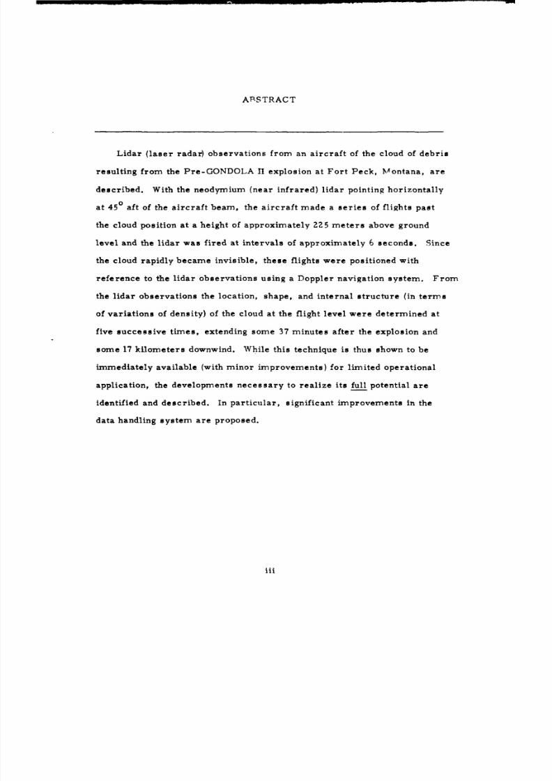
Lidar ( laser radar) observations from an ai rcraf t of the cloud of debris
result ing from the Pre-GONDOLA II explosion at F o r t Peck , Montana, are
described. With the neodymium (near infrared) lidar pointing horizontally
a t 450 af t of the ai rcraf t beam, th e ai rcraf t made a ser ies of flights past
the cloud position at a height of approximately 225 mete r s above ground
level and the lidar was fired at intervals of approximately 6 seconds. Since
the cloud rapidly became invisible, these flights were positioned withreference to the l idar observations using a Doppler navigation sys tem. From
the l idar observations the location, shape, an d internal s t ruc ture (in t e rms
of variations of density) of the cloud at the flight level were determined at
five success ive times, extending some 37 minutes after the explosion and
some 17 kilometers downwind. While this technique is thus shown to be
immediately available (with minor improvements) fo r l imited operational
application, the developments necessary to realize it s full potential are
identified an d described. In particular, significant improvements in the
data handling system are proposed.
111

8/8/2019 pne 1119 Pre-Gondola 2
http://slidepdf.com/reader/full/pne-1119-pre-gondola-2 7/56
ACKNOWLEDGM ENT
We particularly wish to acknowledge the very willing cooperation
received from Edgerton, Gerrneshausen and Grier, Inc., both in prepar ing
the ai rcraf t fo r the experiment and in carrying out the flying experiments,
especially in view of the fact that M r. F. Thompson and hi s crew came
straight to this project from a period of extended flying.
We also wish to acknowledge the assistance and collaboration of
M r. N. Sykos of Lawrence Radiation Laboratory, who acted as Safety
Officer.
lv
8/8/2019 pne 1119 Pre-Gondola 2
http://slidepdf.com/reader/full/pne-1119-pre-gondola-2 8/56
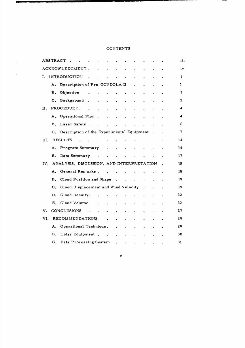
CONTENTS
ABSTRACT . . . . . . . . . . iii
ACKNOWLEDGMENT. . . . . . . . . iv
I. INTRODUCTION 1
A. Description of Pre-GONDOLA II . . . . I
B. Objective . . . . . . . . 3
C. Background .. . . 3
II. PROCEDURE. . . . . . . . . 4
A. Operational Plan . . . . . . . . 4B. Laser Safety . . . . . . . . 6
C. Description of the Experimental Equipment . 7
III. RESULTS . 14
A. Program Summary . . 14
B. Data Summary . . . . . . . . 17
IV. ANALYSIS, DISCUSSION, AND INTERPRETATION 18
A. General Remarks . . 18
B. Cloud Posit ion and Shape . 19
C. Cloud Displacement an d Wind Velocity . 19
D. Cloud Density. I . . . . . . 22
E. Cloud Volume . . . . . . . . 22
V. CONCLUSIONS . . . . . . . . Z7
VI. RECOMMENDATIONS . . . . . . . 29
A. Operational Technique. Z.
B. Lidar Equipment . . . . . . . . 30
C. Data Process ing System 31
v

8/8/2019 pne 1119 Pre-Gondola 2
http://slidepdf.com/reader/full/pne-1119-pre-gondola-2 9/56
VI. RECOMMENDATIONS (Cont)
D. Navigat ion . . . . . . . 37
E. C o m m u n i c a t i o n s . . . . . 39
REFERENCES . . . . . . . . . 41
APPENDIX . . . . . . . . . 42
TABLES
I. Mark V Neodymium Lidar Charac ter i s t ics 10
II. Data S u m m a r y. . . . . . . . . 17
FIGURES
1. Site of Project Pre-GONDOLA II .
2. Successive Ground Tracks of the AircraftDur ing E x p e r i m e n t . . . .
3. Mark V Lidar Optical Diagram . . . . 9
4. Plan View of Scanning Scheme - Airborne Lidar 11
5. Block Diagram of the Mark V Lidar Electronics 12
6. Successive Locations of the Cloud . . 20
7. Cloud Displacement Along Mean Path - 1480 T. z.
8. Relative Density Variations of the Sub-visible Cloud,
Run 3, 6.8 Km From GZ in DB Above Background. Z39. Relative Density Variations of the Sub-visible Cloud,
Run 14 , 11 . 5 Km From GZ in DB Above Background ?4
10. Relative Density Variation of the Sub-visible Cloud,Run 5, 12. 8 Km From GZ in DB Above Background 25
11. Relative Density Variation of th e Sub-visible Cloud,Run 6, 15.6 Km from GZ in DB Above Background 76
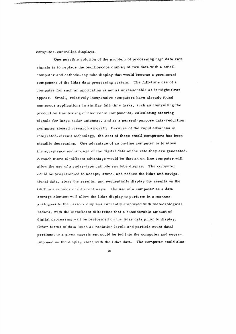
12. Proposed Second-generat ion Data Process ingSystem . . . . . . . . . 36
vi
8/8/2019 pne 1119 Pre-Gondola 2
http://slidepdf.com/reader/full/pne-1119-pre-gondola-2 10/56
I INTRODUCTION
A. Descript ion of Projec t Pre-GONDOLA II
Pro jec t Pre-GONDOLA II wa s a row-charge cra te r ing experiment in
weak, w et clay-shale conducted by the U. S. Army Engineer Nuclear
Cratering Group (NCG) as a par t of the joint Atomic Energy Commiss ion /
Corpq of Engineers nuclear excavation research program. Th e pr imary
purpose of this nominal 140-ton 5-charge row-charge experiment was to
gain row-charge cratering experience in a weak, w et medium. In addition,
this experiment tested techniques fo r connecting a row-charge crater to an
existing cra ter and fo r over-excavating to accept throwout from a follow-on
connecting row-charge cra ter.
Pro jec t Pre-GONDOLA II wa s detonated ýLtValley County, near the
edge of the F o r t Peck Reservoi r approximately 18 miles south of Glasgow,
Montana, at exactly 0800 hours (MDT), 28 June 1967 (see Fig. 1). Coor'li-
natesof the center charge were W106 0 38' 31", N47 0 55' 51". The orientat ion
of the row was along a 110 Eas t of North to 11°0 West of South al inemnnt ex-
tending through' the center of Charl ie Crater.
Th e average lip cres t to li p c r e s t dimensions after connection to the
Charl ie Crater were 640 ft x 280 ft. Individual charge yields, depth,
spacing, and result ing apparent cra ter dimensions were as follows:
I
8/8/2019 pne 1119 Pre-Gondola 2
http://slidepdf.com/reader/full/pne-1119-pre-gondola-2 11/56
Missouri R.
Glasgow MONTANA
4"'.~
' Sp.illwa
)I ~Fort Peck Dom
0, buIck Creek Inlet
/ '• •Pre-Gondola "
Pirtes Pecre wicn Cm
) Airport Paved Road Scale in Miles
4+ Landing Strip ....- Graded Road 0
FIG I CITE OF PROJECT PRE-GONDOLA 3r
2
8/8/2019 pne 1119 Pre-Gondola 2
http://slidepdf.com/reader/full/pne-1119-pre-gondola-2 12/56
II PROCEPURE
A. Operational Plan
The operat ional plan, which had been rehearsed riurin, the test fli:,.ht
of 27 June, called fo r the initial posi t ioning of the NATC ai rcraf t to the
southwest of ground zero. From this position, the ai rcraf t could becin
the f i rs t ru n pas t the cloud immediately after the ao-ahead wa s received
from the test director.
Th e th ree-man SR I crew aboard the ai rcraf t were emplo 'ed in the
following way. An observer st-Lioned at the l idar sightinc telescope con-
t rolled the firing of the lidaro He commanded a view of the entire region
surrounding the aiming point of the l idar. The l idar re turn signal was dis-
played on a Tektronix oscil loscope upon which w as mounted a recordin, .
c a m e r a . Th e second observer photographed each return signal on Polaroid
film, and also monitored the per formance of the l idar apparatus. The third
observer w as stationed at an auxil iary oscil loscope, and visually monitored
each l idar return fo r the presence or absence of a return signal from the
cloud. In addition, the Lawrence Radiat ion Laboratory l aser safety coordin-
a to r w as l oca t ed ad jacen t to th e l i da r siL,!htinu" s t a t ion , an d cou ld e l e c t r i c a i l
inhibit the firing of the l idar at any tiim;e he deemed necessarv.
After the detonation, the aircraft w as flown on a ser ies of courses,
t ha t had been p l anned prev ious ly with rc.rd 'm,dind d i rec t ion an d velc
(See Fig. 2). The l idar commenced firinf, well ahead of the estimated
position of the cloud, and continued firinu ,nlil no further cloud re turns were
received on each run.
T h e intent ion w as to use th e aircraft's Flopp . r n a v i g a t i n sys ten to
8/8/2019 pne 1119 Pre-Gondola 2
http://slidepdf.com/reader/full/pne-1119-pre-gondola-2 13/56
N 2Z
o I 10STAiLTE MILES
FIG 2 SUCCESSIVEGROUNDTRACKS OF THE AIRCRAFT DURING THE EXPERIMENT
6

8/8/2019 pne 1119 Pre-Gondola 2
http://slidepdf.com/reader/full/pne-1119-pre-gondola-2 14/56
provide a f rame-work of reference for making the observations and for
providing ass is tance to the pilot to maintain accurate courses during the
observa t ions . Thus, the Doppler plot was started on a recognizable land-
m a r k (the Doppler Point) an d oriented so that it s track was parallel to the
expected downwind path of the debris cloud and sufficiently to one side to
allow the l idar observations to be made . Each ser ies of l idar observa t ions
w e r e to be started a t a point along this track, which w as called the Lidar
Point fo r the ru n in question. In this way, it w as hoped that a substantial
pa r t of the program could be carr ied ou t without changing the ke y Doppler
Point . F or each pass a new Lidar Poin t would be selected along the
Doppler track in accordance with the experience of the cloud motion, to
indicate a t what t ime th e l idar shots should begin.
The advantages of this system were that the pilot could position his
ai rcraf t at the s tar t of the ru n on good l andmarks . He could then fly the
"selected t racks with the aid of the Doppler system by maintaining a course
that yielded zero drift indications on th e Doppler indicator. The Doppler
indications of distance along th e track then provided an indication of when
th e l idar observa t ions should begin.
Since it was intended to make observa t ions on both downwind and upwind
passes , an identical Doppler positioning scheme was planned fo r the re turn
upwind p a s s e s .
To provide running checks of the Doppler e r ro r each Doppler ru n wa s
to be closed on an identifiable l andmark . Cince the data record ing sys tem
ha d provision for mark ing an y desired "event" (including l idar fir ings, and
recording the coincident Doppler plot position), it w as hoped that t 'ubsequent
analysis would cnable a ll l idar f ir ings to be related rigorously to ground
7
8/8/2019 pne 1119 Pre-Gondola 2
http://slidepdf.com/reader/full/pne-1119-pre-gondola-2 15/56
posit ions.
At th e termination of each run, photographs of the l idar re turns were
examined and compared with a m ap showing the ground t rack of the ai rcraf t .*
F r o m this information an d from the estimated wind data, the size of the
cloud an d its future position were estimated, and the pre-planned courses
w e r e modified as requi red to properly position the next ru n with respect to
the moving cloud. Repeated runs were made in the manner described above
until contact with the clo ud wa s lost .
B. L a s e r Safety
All l idar observa t ions were made in accordance with the procedures and
safety cr i ter ia outlined in Annex B of the "Technical Director ' s Operations
Plan fo r Pre - GONDOLA II.,
Th e safety plan w as based on visual surveil lance of the volume of space
surrounding the l idar ?ath. This volume w as moni tored by the l idar operator
with the ai d of a sighting telescope whose optical axis w as alined parallel to
the l idar beam. The l idar was not f ired when ai rcraf t were within the field
of view of the sighting telescope, or when the ai rcraf t attitude was such that
the l idar beam could strike the ground. In addition, the safety coordinator
independently scanned th e genera l area around the l idar beam with binoculars
and could inhibit firing of the l idar if he deemed it necessary.
C. Descr ip t ion of the Exper imenta l Equipment
1. Mark V Lidar
Th e Mark V l idar t ransmit te r consisted of a Q-switched, neodymium-
* Th e ground track of the ai rcraf t wa s plotted by th e Edgerton, Germeshausen
and Grier technical crew from data obtained from the Doppler navigationsystem.
8
8/8/2019 pne 1119 Pre-Gondola 2
http://slidepdf.com/reader/full/pne-1119-pre-gondola-2 16/56
doped glass laser whose output radiation occurs in the near- inf rared
portion of the spectrum at a wavelength of 1. 064. Th e laser is capable
of producing pulsed coherent radiation of 15 nanoseconds duration, with a
peak power output of 25 Megawatts . Th e laser output bearr divergence
(beamwidth) is approximately 5. 6 mil l i rad ians . Since the angular reso-
lution of the l idar is determined by the transmitted beam divergence,
coll imating optics ar e used to reduce the beam divergence and to produce
an output bearmwidth of 0. 35 mil l i rad ians . Th e corresponding two-dimensional
spatial resolution of this beam is 0. 35 m at the range of I km . Th e range
resolution of the equipment is 2. 3 m. Th e pulse-repeti t ion rate (PRR) of
th e Mark V l idar is pr imar i ly l imited by the ambient air t empera ture ,
which determines the cooling rate of the l a se r head. F o r the t empera ture
encountered during th e observations discussed here , the maximum PR R
that could be attained was approximately 12 pulses per minute.
Th e l idar rece iver consists of a 6-inch diameter Newtonian reflecting
telescope, identical to the t ransmit te r optics. An adjustable field stop at
the focal plane l imits the rece iver acceptance angle to a maximum of 6
milliradians. A multi layered interference fi l ter with a wavelength interval
(bandwidth) of 0. 014 is inserted in the rece iver optical path to reduce the
output noise level produced by solar radiation scattered into the receiver
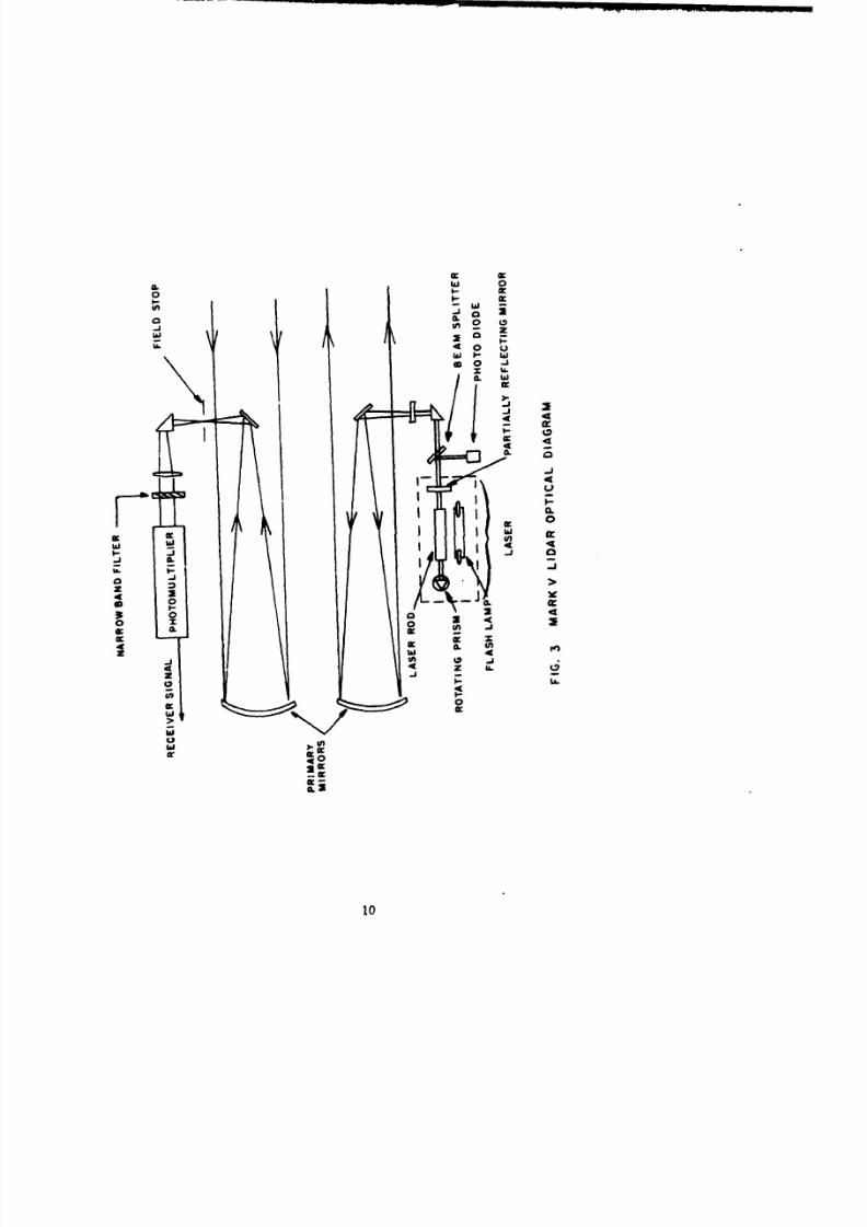
field of view. The dec tec tor consists of an RCA 7102 photornultiplier with
an S-1 spec t ra l response. An optical diagram of the l idar is shown in
Fig. 3.
A detailed discussion of l idar detection of a tmospher ic t a rge ts and
l idar equipment design features is beyond the scope of the present repor t .
These topics are treated extensively in Refs. 1, 2, and 3.
9
8/8/2019 pne 1119 Pre-Gondola 2
http://slidepdf.com/reader/full/pne-1119-pre-gondola-2 17/56
9L w 0
0 I 0-
o6 I 0w~ wi
LaC.
a. Ix i
0 CL I00
w IA.L
w 0
.. ). g.4.z cc
00
0,2
10

8/8/2019 pne 1119 Pre-Gondola 2
http://slidepdf.com/reader/full/pne-1119-pre-gondola-2 18/56
Table I summarizes the pertinent charac ter i s t ics of the Mark V l idar.
Th e l idar t ransmit te r and rece iver were located on the por t side of
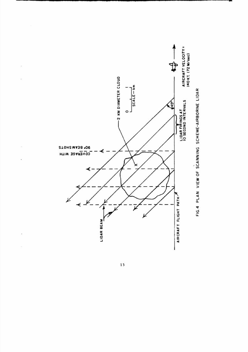
the ai rcraf t , jus t af t of the existing electronic equipment rack . Th e lidar
was mounted so that it looked horizontally in a direction 45 degrees af t
of the ai rcraf t ' s beam to the left . (In this way, as shown in Fig. 4, the
number of shots traversing the cloud was increased). Th e remaining
units of the l idar were mounted at various locations in the nearby electronic
equipment rack. Three cylinders of compressed nitrogen provided energy
fo r the laser Q-switching turbine. *
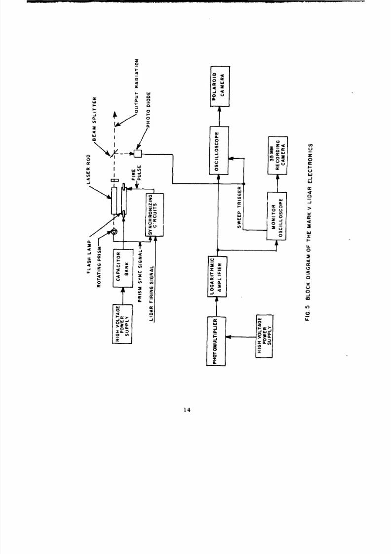
2. Electronics and Data Recording Equipment
Th e major electronic components of the l idar and the data record-
ing system are illustrated in block diagram form in Fig. 5. A compressed
ai r-dr iven turbine rotates the laser Q-switching prism at 500 revc•utions
pe r second. Upon receipt of a fire signal, the synchronizing generator
tr iggers the flash lamps in step with a signal from the rotating pr ism. A
capacitor bank charged to approximately 3 kV supplies energy fo r th e laser
flash lamps. A photo diode senses the occur rence of the laser pulse and
produces a t r igger to s tar t the data recording equipment. Th e output of
the photomult ipl ier in the lidar rece iver is fed to a pulse ampl i f ie r having
a logari thmic t ransfer function, and then to two Tektronix 453 oscil loscopes.
A Polaroid recording camera mounted on one oscilloscope facil i tated the
initial alinerr-3nt of the equipment and w as used to photograph the lidar
return signal. An independent backup system consisting of a manually
operated 35-mm recording camera mounted on an auxil iary oscil loscope
Th e electric motor-driven air compressor normally associated with thel idar could no t be used because of pr imary power l imitat ions aboard theai rcraf t .
11

8/8/2019 pne 1119 Pre-Gondola 2
http://slidepdf.com/reader/full/pne-1119-pre-gondola-2 19/56
Table I
MARK V NEODYMIUM LIDAR CHARACTERISTICS
Transmi t te r
Lase r Neodymium-doped glass
Wavelength 1. 06ýi
Beamwidth 0 .3 5 Milliradian
Optic s 6-inch f/ 4 Newtonian reflector
Peak P o w e r Output 25 Megawatts
Pulse Length 15 Nanoseconds
Q-switch Rotating prism
Receiver
Optic s 6-inch Newtonian reflector
Field of View 3. 0 Milliradians
Pre-Detec t ion Fi l ter 0.01 (100A)Wavelength Intervel
Detector RCA 7102 Photomultiplier (S-1 cathode)
Post-Detection Fi l ter 28 GHzBandwidth
12
8/8/2019 pne 1119 Pre-Gondola 2
http://slidepdf.com/reader/full/pne-1119-pre-gondola-2 20/56
r0*
VI c
W
00
-JL
> z
0L02
LL c
13-
8/8/2019 pne 1119 Pre-Gondola 2
http://slidepdf.com/reader/full/pne-1119-pre-gondola-2 21/56
w a. 0
0 04
0 -0
0
w~ 9L
0o 0
0
w w
U 0
0r -aWo
w
0 u 4
C, 0
0
L.4
0
cn CL 0
L)6z -.
Z 14
8/8/2019 pne 1119 Pre-Gondola 2
http://slidepdf.com/reader/full/pne-1119-pre-gondola-2 22/56
Ias used. to photograph each t race. A telephone systeni wa s installed to
facil i t i te communicat ion between the three-mnan l idar teanm and the safety
coordinator. An audio tape recorder connected to the telephone line was
used to record various equipment settings, as well as a running con.r.,.entary
on the progress of the experiment. In addition, the observer stationed at
tI'e lidar sighting te lescope had access to the ai rcraf t ' s normal intercn-r.-uni-
cation system.
A 70-mm view camera was instal led near the l idar A photograph was
automatically taken at every firing of the region surrounding the l idar field
of view.
3. Aircraf t Equipment
Data concerning the t ravel of the aircraft over the ground was ob-
tained from the Doppler radar navigation systenm (AN/APN-183) aboard the
aircraft . The instantaneous coordinates* of the aircraft were printed on
paper tape at every firing of the l idar.
Additional navirat ional data were printed in tabular form by a t . le-
t-ype unit as,;ociated with the a i rcraf t digital con-puter ,-torr. The data
(which included altitude, grounaspe-. i , magnetic headinc, drif t angl,, 'virei
speed, and direction) were printed ou t at e--ery firinf, of the l idar.
Refe renced to a r e c t a n g u l a r coord ina t e system that i n c luded a know- .tn.rt-inv and ending point for each run.
15
8/8/2019 pne 1119 Pre-Gondola 2
http://slidepdf.com/reader/full/pne-1119-pre-gondola-2 23/56
III RESULTS
A. P r o g r a m Summary
Th e modifications to the NATS ai rcraf t required fo r this exper iment
w e r e accomplished by E. G. and G. at the aircraf t ' s home base .
The m a j o r modifications were :
(1) Construction of a mount fo r the l idar t ransmit te r andrece iver
(2) Construction of viewing ports fo r the l idar at an existing
escape hatch
(3) Provis ion of 110 volt, 60-Hz power
(4) Provis ion of a power distribution panel
(5) Provis ion of mounting ar rangements fo r the othercomponents of the l idar sys tem.
On 7 June, the NATS a i r c r a f t (a Mart in 404) arr ived at San Francisco
International A i r p o r t fo r a t r ia l installat ion of the l idar equipment. Th e
equipment w as installed during the day. On the following morning, the
l idar w as alined an d checked fo r proper operation. A tes t flight in the
local areas w as conducted in the afternoon to verify the proper operation
of the equipment under actual operating conditions. At this t ime, a care-
fu l check w as made to determine if operat ion of the l idar would produce
elec t r ica l t rans ien ts capable of interfering with the proper operation of
other equipment aboard the ai rcraf t . Also, the operation of the l idar wa s
moni tored to verify that operation of the aircraf t ' s electrical and electronic
equipment would no t produce spurious tr iggering of the l idar. A ll equipment
aboard the ai rcraf t per formed properly, and no interference of either kind
w as observed . A number of runs were made past severa l smal l cumulus
clouds to simulate the cloud t racking operation. Th e purpose of these runs
1 6

8/8/2019 pne 1119 Pre-Gondola 2
http://slidepdf.com/reader/full/pne-1119-pre-gondola-2 24/56
w as to obtain an appreciat ion of the t ime scale involved in t racking re la-
tively smal l clouds with a fas t moving ai rcraf t . A secondary purpose
w as to obtain l idar data that w as later used to optimize the various sett ings
of the l idar equipment. Th e duration of the test flight w as approximately
2. 5 hours. On 9 June the l idar equipment was removed, and the ai rcraf t
re turned to it s home base .
The original schedule was such that the ai rcraf t would be available at
Glasgow, Montana, fo r severa l days before the shot . A number of test
f l ights ha d been planned during which time the l idar t racking and plotting
technique could be optimized. Because of higher priority commitments of
th e ai rcraf t , it became n e c e s s a r y to delay the instal lat ion of th e l idar until
the morning of 27 June. The SRI crew, with the equipment, m et the air-
c raf t a t Twin Falls, Idaho. - Th e instal lat ion w as comple ted during the
flight from Twin Falls to Glasgow. A tes t flight w as made in the late af te r-
noon of V7 June but w as necessar i ly l imited to checking ou t the equipment
and establishing an ini t ial plan of operat ion of a minimum nature.
All equipment functioned proper ly. The duration of the tes t flight wa s
approximately one hour.
In the actual observational flight on the morning of the 28th, some
difficulties arose in connection with the proper positioning of th e ai rcraf t ;
also, because of insufficient time, it had niot been possible to put the 70-mm
view c a m e r a in effect ive operat ion. A malfunction occurred in the digital
computer that resulted in loss of the data normally printed ou t on the tele-
type unit. Th e main problem w as at the interface between the ai rcraf t
Th e l idar was involved in another project there.
17

8/8/2019 pne 1119 Pre-Gondola 2
http://slidepdf.com/reader/full/pne-1119-pre-gondola-2 25/56
crew and the l idar crews. This resulted inevitably from th e from th e lack
of preparation and prac t ice cause- ' bv th e cur ta i lment of the test flight
per iod . Again, shortcomings in the intercommunication bysterr between
th e crews could not be rectif ied in the t ime available. The experimental
method descr ibed in Section II-A was fol lowed, an d th e cloud w as success -
fully observed by l idar during five of th e f i rs t six runs. Contact with the
cloud w as los t af te r ru n si x (approximately 38 minutes after detonation)
and th e remaining four runs failed to re-es tabl i sh contact with the cloud.
Th e l idar equ ipment operated without malfunction during th e entire
flight. Th e duration of the observational flight w as approximately two hours.
A pre l iminary reduction of the data w as accomplished af te r the flight,
and an informal letter r e p o r t describing the exper iment an d th e pre l iminary
resul t s were submitted on the evening of 28 June.
The following day, th e ai rcraf t stopped a t Twin Fal l s on it s re turn
trip, where th e l idar equ ipment w as removed.
An Interim Data Report w as submitted on 24 July 1967.
18

8/8/2019 pne 1119 Pre-Gondola 2
http://slidepdf.com/reader/full/pne-1119-pre-gondola-2 26/56
B. Data Summary
TABLE II. S u m m a r y of l idar data obtained in this exper iment
Ptar t Time En d Time Number of Number of Shots
Ru n No. (MDT) (MDT) Shots Fired Travers ing Cloud
1 0804:43 0805:42 7 1
2 0808:35 0809:56 9
3 0812:24 0814:33 9 6
4 0822:15 0826:05 23 6
5 0829:22 0830:16 8 6
6 0835:10 0838:20 24 6
7 0847:00 0850:26 28
8 0856:00 0900:00 21 -
9 0913:00 0916:45 41 -
10 0920:00 0926:00 46
Total 21 6
The prirnar-.ý data for this repor t consisted of the 216 l idar re turns
recorded on Polaroid film along with the ground coord ina tes of th e a i r c r a f t
cor respondina to each l idar shot.
19
8/8/2019 pne 1119 Pre-Gondola 2
http://slidepdf.com/reader/full/pne-1119-pre-gondola-2 27/56
IV ANALYSIS, DISCUSSION, AND INTERPRETATION
A. General Remarks
After the detonation, which occur red a t 0800 MDT, th e main ser ies of
runs were made at an altitude of approximately 225 m e t e r s above the t e r r a in
in such a way that on each run, a succession of l idar shots probed a hor i -
zontal plane intersecting the cloud. Each run was intended to provide opti-
m um viewing of the cloud as it w as displaced by the wind. On each run,
the l idar was f ired at regular intervals (a t a rate of approximately 10 per
minute), start ing from a point well ahead of the cloud's es t imated position
an d continuing unti l nc fur ther echoes were recorded .
The ai rcraf t maintained a true a i r speed of approximately 155 knots,
giving a downwind ground speed of 165 knots an d an upwind ground speed
of 145 knots . A t these speeds, l idar shots were made a t approximately 552
m e t e r intervals along the track on downwind runs an d a t intervals of 485
m e t e r s on upwind runs. Diff icult ies were experienced in positioning the
ai rcraf t an d the runs made were badly located with r e s p e c t to the cloud;
in addit ion, the runs were made at overlong intervals in some cases . (It
should be reca l led that the cloud became bare ly perceptible to the ey e
shortly after the detonation and w as quite invisible by about minute 15).
Th e top of the cloud did no t appear to rise above 250 m e t e r s or so
above ground level and rapidly became quite tenuous as it moved a t a
velocity subsequently measured a t 148 degrees (T), 7. 0 m e t e r s per second.
Th e furthest distance of dust detection w as 6. 7 km a t 29 minutes, 55
seconds af te r detonation. At this t ime the cloud was some 13. 8 krn from
ground zero. Th e greatest distance from ground zero at which the cloud
20

8/8/2019 pne 1119 Pre-Gondola 2
http://slidepdf.com/reader/full/pne-1119-pre-gondola-2 28/56
w as observed w as 16. 5 km at minute 37.
Extensive searching failed to re-es tabl i sh contact with the cloud after
Run 6 (the last return being obtained at minute 37:36). By this time the
cloud had become very diffuse, bu t it is probable that some further t rack-
ing could have been achieved ha d the ai rcraf t positioning been fully effective.
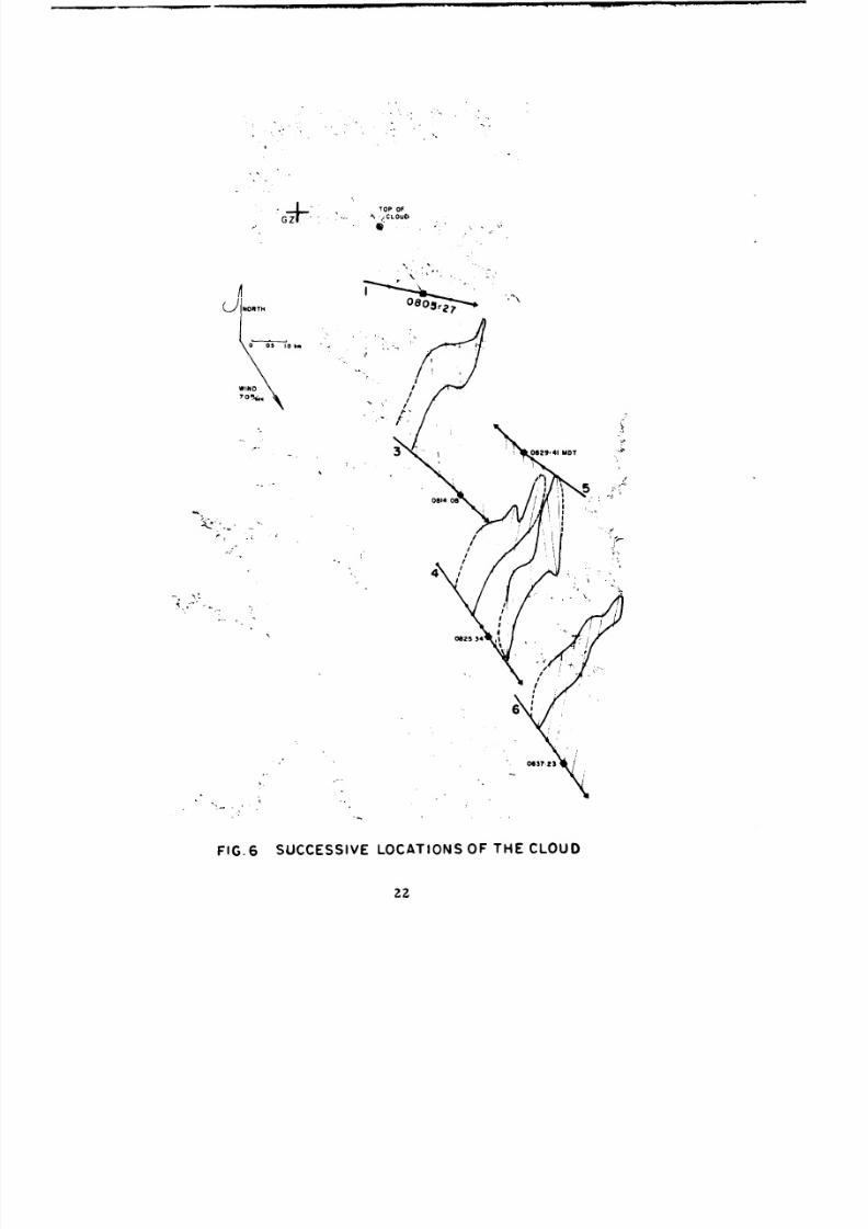
B. Cloud Posit ion and Shape
Figure 6 shows the successive locations of the cloud as it w as displaced
by the wind. The ai rcraf t t racks are shown, each identified by the ru n num-
ber ; along each t rack the position at which the l idar was f ired is indicated.
(Only signif icant l idar shots a re so indicated) . Th e position of th e lidar
points has been adjusted on the bas is of th e measured wind displacement to
give the optimum representation of th e shape of the cloud a t mid- t ime (cen-
tered on the position indicated with a square) .
Th e orientation of the m a j o r axis of the cloud is in good agreement with
the orientat ion of the Pre -GONDOLA It cra ter, an d does not appear to change
significantly with time. The shape of th e observed port ion of th e cloud does
not change rapidly with time; this charac ter i s t ic agrees fairly well with the
behavior of Pre -GONDOLA I Delta event , where an approximately circular
cloud w as t racked fo r 10 minutes . Meaningful conclusions concerning cloud
size and growth cannot be presented because of th e l imited sampling of
only a portion of the cloud. However, it is interest ing to note that the size
of the observed port ion of the cloud did not appear to increase as rapidly
as the Pre -GONDOLA I Delta Cloud 4 . F o r example, in the t ime interval
between 0814:08 and 0837:23 (see Fig. 6) the cloud size increased by a factor
of 1. 3. During the Pre -GONDOLA I Delta event , in the t ime interval from
three minutes to ten minutes af te r the detonation, the cloud size increased
21
8/8/2019 pne 1119 Pre-Gondola 2
http://slidepdf.com/reader/full/pne-1119-pre-gondola-2 29/56
G+ .TOP OF
CLOUO,
0I 01 0." ...
WINDO
O"/"
"302941 M*DT
"- -II ,, [y°\' Y •i, -.9:•"5
082534
//
FIG.6 SUCCESSIVE LOCATIONS OF TH E CLOUD
2z
8/8/2019 pne 1119 Pre-Gondola 2
http://slidepdf.com/reader/full/pne-1119-pre-gondola-2 30/56
by a factor of 2. 4.
C. Cloud Displacement an d Wind Velocity
Th e successive locat ions of the cloud along the mean path Fig. 6 ar e
plotted as a function of t ime and shown in Fig. 7. Th e displacement is
seen to be remarkably regular at the height of the observations (approxi-
mately 225 meters above the surface) and cor responds to a wind velocity
of 7 .0 meters per second from 328 degrees (T).
It is also interest ing that th e trajectory of the cloud in Fig. 6 does not
originate at ground zero. This is probably partly due to the uncertainty in
determining the mean path an d the position of the cloud relat ive to the mean
path was anomalous in i ts early stages (due to different wind direct ions at
the lower level), apparent e r roneous motions along the mean path would
resu l t from the plotting procedure employed in Fig. 7.
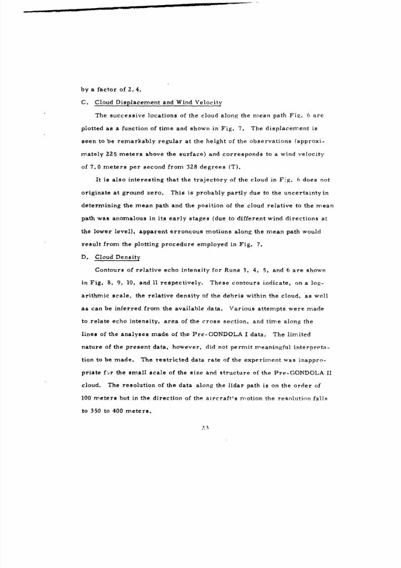
D. Cloud Density
Contours of relat ive echo intensity fo r Runs 3, 4, 5, and 6 are shown
in Fig. 8, 9, 10 , an d 11 respectively. These contours indicate, on a log-
ari thmic scale, the relat ive density of the debris within the cloud, as wcll
as ca n be inferred from the available data. Various attempts were made
to relate echo intensity, area of the cross sect ion, and t ime along the
lines of the analyses made of the Pre-GONDOLA I data. Th e l imited
nature of the present data, however, did no t permi t meaningful in te rpre t s -
tion to be made. Th e res t r ic ted data rate of the experiment was inappro-
priate f-,r the small scale of the size an d structure of the Pre-GONDOLA II
cloud. The resolution of the data along the l idar path is on the order of100 m e t e r s bu t in the direction of the ai rcraf t ' s motion the resolution falls
to 350 to 400 m e t e r s .
1-;

8/8/2019 pne 1119 Pre-Gondola 2
http://slidepdf.com/reader/full/pne-1119-pre-gondola-2 31/56
29
w 0
-J
a. z 1
0 0.
a.a
0
2W

8/8/2019 pne 1119 Pre-Gondola 2
http://slidepdf.com/reader/full/pne-1119-pre-gondola-2 32/56
N
0 15
2~J~15LEur
flG.WIN 7ELps
CLOUDR R M c z I aA~
8/8/2019 pne 1119 Pre-Gondola 2
http://slidepdf.com/reader/full/pne-1119-pre-gondola-2 33/56
I
/I
/0 N
// WIND 7mps
GROUND II ,
TRACK SCALE- kmn
/
FIG 9 RELATIVE DENSITY VARIATIONS OF THE SUB- VISIBLECLOUD RU N 4 11.5kim FROM GZ IN DB ABOVE BACKGROUND
26

8/8/2019 pne 1119 Pre-Gondola 2
http://slidepdf.com/reader/full/pne-1119-pre-gondola-2 34/56
0829:41
AIRCRAFTGROUNDTRACK
N
IWINO iraps /J
10
'5
0 .5
SCALE--km/
II
FIG.AO RELATIVE DENSITY VARIATION OF THE $US-VISIBLECLOUD RUN 5 12.8kim FROMGZ IN DO ABOVE BACKGROUND
27

8/8/2019 pne 1119 Pre-Gondola 2
http://slidepdf.com/reader/full/pne-1119-pre-gondola-2 35/56
N
l0
//
15 WIND 7mrs
15 '
AIRCRAFT
TRACK
0837;23
0
SCALE-km
FIG II RELATIVE DENSITY VARIATION OF THE SUB-VISIBLECLOUD RU N 6 15.6km FROM GZ IN DB ABOVE BACKGA,,.';:.
2R

8/8/2019 pne 1119 Pre-Gondola 2
http://slidepdf.com/reader/full/pne-1119-pre-gondola-2 36/56
8/8/2019 pne 1119 Pre-Gondola 2
http://slidepdf.com/reader/full/pne-1119-pre-gondola-2 37/56
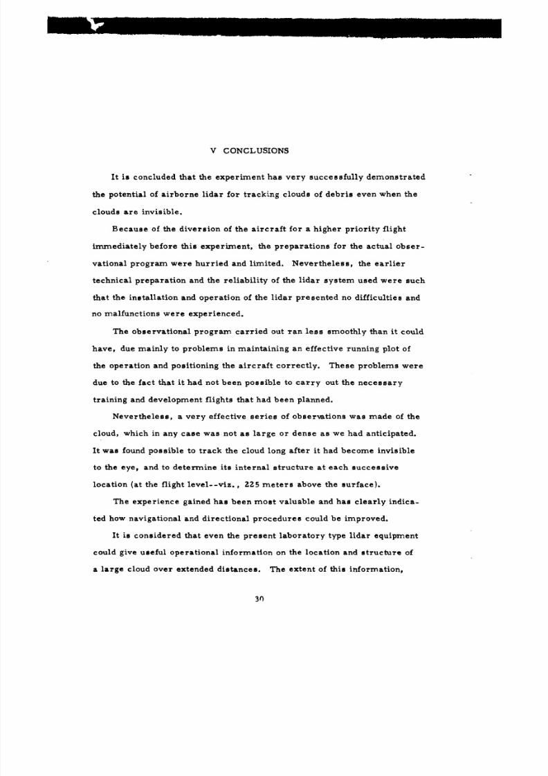
V CONCLUSIONS
It is concluded that the experiment ha s very successfully demonstrated
the potential of airborne l idar fo r tracking clouds of debris even when the
clouds ar e invisible.
Because of the diversion of the aircraft fo r a higher priori ty flight
immediately before this experiment, the preparations fo r the actual obser-
vational program were hurried and limited. Nevertheless, the earl ier
technical preparation and the reliability of the l idar system used were such
that the installation and operat ion of the l idar presented no difficulties and
no malfunctions were experienced.
The observat ional program carried ou t ra n less smoothly than it could
have, due mainly to problems in maintaining an effective running plot of
the operation and positioning the aircraft correctly. These problems were
due to the fact that it ha d not been possible to car ry out the necessary
t raining and development flights that had been planned.
Nevertheless, a very effective series of observations was made of the
cloud, which in any case was no t as large or dense as we ha d anticipated.
It wa s found possible to t rack the cloud long after it had become invisible
to the eye, and to determine i ts internal structure at each successive
location (a t the flight level--viz. , 225 meters above the surface) .
The experience gained has been most valuable and ha s clearly indica-
ted how navigational and direct ional procedures could be improved.
It is considered that even the present laboratory type lidar equipment
could give useful operational information on the location and structure of
a large cloud over extended distances. The extent of this information,
3n
8/8/2019 pne 1119 Pre-Gondola 2
http://slidepdf.com/reader/full/pne-1119-pre-gondola-2 38/56
however, would depend signif icantly upon the data-handling ar rangements
used in this tr ial . Var ious possibil i t ies fo r improving this aspec t of the
application are apparent, however, and their adoption should be considered
in t e rms of the operat ional r e q u i r e m e n t and the economics involved.
For ear ly applicat ion of the currently available l idar, no m a j o r changes
appear needed in the instal lat ion ar rangements , although improvements
could readily be made in the area of providing power, particularly fo r the
operat ion of the Q-swi tch .
Ways in. which the subsequent development of improved l idar systems
fo r this purpose should be approached emerge fairly clearly from the ex-
perience gained, an d future p r o g r a m s in this area will benefi t accordingly.
31
8/8/2019 pne 1119 Pre-Gondola 2
http://slidepdf.com/reader/full/pne-1119-pre-gondola-2 39/56
VI RECOMMENDATIONS
A. Opera t iona l Techniques
Recommendations regarding improvements in operational techniques
are int imately related to the recommendat ions made regarding equipment
developments and data process ing d iscussed in detai l below. Again, the
very important question of positioning the ai rcraf t fo r making the observa-
tions is discussed in detail separa te ly.
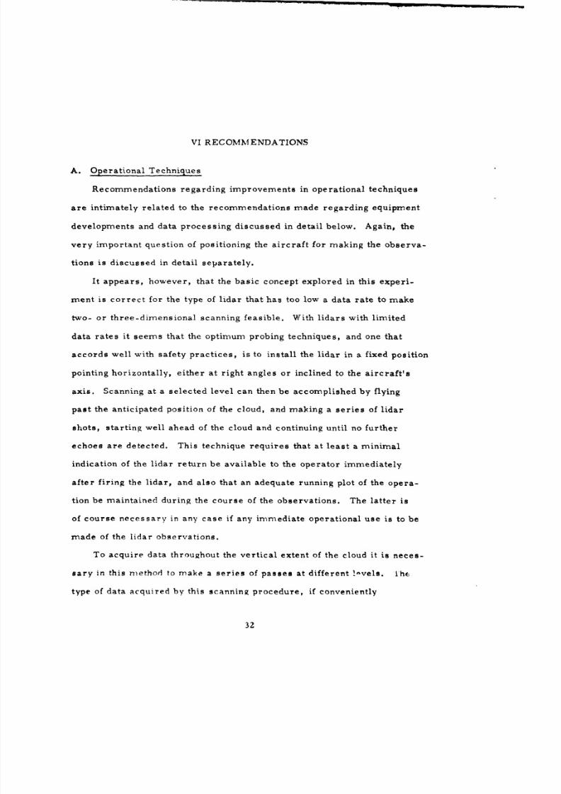
It appears, however, that the basic concept explored in this experi-
m e n t is correc t fo r the type of l idar that has too low a data rate to make
two- or th ree-d imens iona l scanning feasible. With l idars with l imited
data ra tes it seems that the optimum probing techniques, an d one that
accords well with safety practices, is to instal l th e l idar in a fixed posit ion
point ing horizontally, ei ther at r ight angles or incl ined to the ai rcraf t ' s
axis . Scanning at a selected level ca n then be accomplished by flying
pas t the anticipated position of the cloud, and making a ser ies of lidar
shots, start ing well ahead of the cloud and continuing until no further
echoes are detected. This technique requi res that at l eas t a minimal
indication of the l idar return be available to the opera tor immediately
after firing the l idar, and also that an adequate running plot of the opera-
tion be maintained during the course of the observations. Th e lat ter is
of course necessary in any case if any immediate operat ional use is to be
made of the l idar observations.
To acquire data throughout the vertical extent of the cloud it is neces-
sary in this method to make a ser ies of passes at different , -vels. the
type of data acquired by this scanning procedure , if conveniently
32

8/8/2019 pne 1119 Pre-Gondola 2
http://slidepdf.com/reader/full/pne-1119-pre-gondola-2 40/56
an d rapidly presented, appears to be very suitable for many operat ional
purposes. With l a rger clouds, the l imitat ions of data rate an d resolution
noticed in probing the Pre -GONDOLA II cloud would be less res t r ic t ive .
In fact , the type of scanning proposed is m o s t effective in the case of
very extended or diffuse clouds.
B. Lidar Equipment
Th e design of an operat ional airborne l idar should no t necessar i ly
be based upon the current M a r k V equipment. The f i rs t step in planning
for an optimum operat ional l idar should include a sys tems analysis study
to accomplish the following:
(1) Define the operat ional requi rements that the prospective
equipment m u s t satisfy.
(2) Define an optimum ar rangement of equipment that will
satisfy the operat ional requirements, within various
prac t ica l cons t ra in t s (such as available t ime an d fund-
ing, the per formance l imits of present and future equip-
ment, and laser safety) .
A study of this nature would yield a number of advantages:
(1) It would provide high performance equipment well suited
to the operat ional requirements at a minimum cos t .
(2) It would provide a unified plan fo r gradually upgrading
the equipment as the future operat ional requi rements
become m o r e severe.
(3) It will resu l t in a smal le r, more compac t system which
could be installed in a smal le r, more maneuverab le
33
8/8/2019 pne 1119 Pre-Gondola 2
http://slidepdf.com/reader/full/pne-1119-pre-gondola-2 41/56
ai rcraf t , thus significantly reducing direc t operating
costs.
In shor t , a sys tems study of modes t p ropor t ions could make the
difference between an effective l idar cloud t racking system and one of
margina l usefulness.
A study of this nature is beyond the scope of the present repor t ;
however, because of th e experience gained during th e a i rborne program,
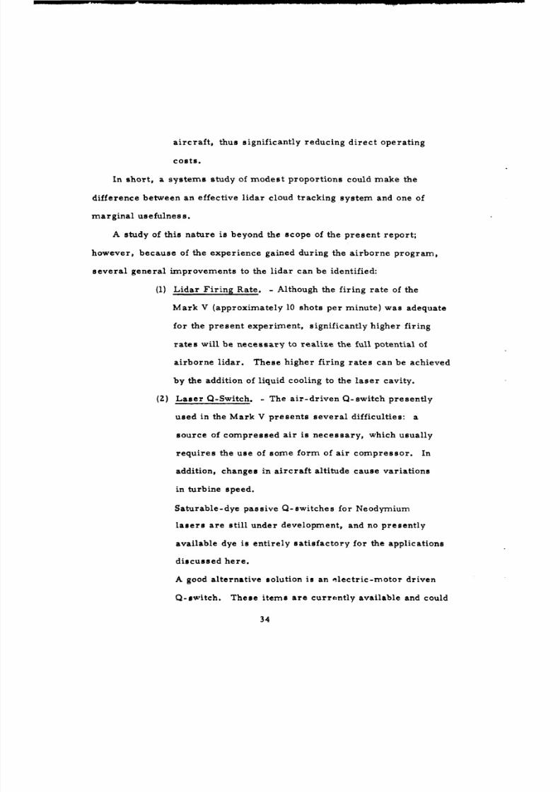
severa l genera l improvements to the l idar ca n be identified:
(1) Lidar Firing Rate. - Although the firing rate of the
Mark V (approximately 10 shots per minute) w as adequate
fo r the present experiment, s ignificantly higher fir ing
rates will be necessary to realize the full potential of
airborne l idar. These higher f ir ing rates ca n be achieved
by the addition of liquid cooling to the laser cavity.
(2) Laser Q-Switch. - Th e ai r-dr iven Q-switch presently
used in the Mark V presents severa l difficulties: a
source of compressed air is necessary, which usually
requi res th e us e of some form of air c o m p r e s s o r. In
addition, changes in ai rcraf t altitude cause variations
in turbine speed.
Saturable-dye passive Q-switches fo r Neodymium
lasers are still under development, and no presently
available dye is entirely satisfactory fo r the applications
discussed here.
A good alternative solution is an elec t r ic -motor driven
Q-switch. These i tems a re currently available and could
34
8/8/2019 pne 1119 Pre-Gondola 2
http://slidepdf.com/reader/full/pne-1119-pre-gondola-2 42/56
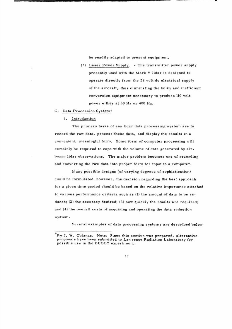
be readily adapted to p r e s e n t equipment.
(3) Laser P o w e r Supply. - The t ransmit ter power supply
presently used with the Mark V l idar is designed to
operate directly from the 28 volt dc electrical supply
of the ai rcraf t , thus eliminating the bulky an d inefficient
conversion equipment necessary to produce 110 volt
power either at 60 Hz or 400 Hz.
C. Data Process ion System*
1. Introduction
Th e pr imary tasks of any l idar data processing system are to
record the raw data, process these data, an d display the results in a
convenient, meaningful form. Some form of computer process ing will
certainly be required to cope with the volume of data generated by air-
borne l idar observations. Th e m a j o r problem becomes one of recording
and convert ing the raw data into proper form for input to a computer.
Many possible designs (of varying degrees of sophist ication)
could he formulated; however, the decision regarding the b e s t approach
fo r a given time period should be based on the relative importance attached
to various performance cr i ter ia such as (1) the amount of data to be re -
duced; (2 ) the accuracy desired; (3) how quickly the results ar e required;
and (4) the overall costs of acquiring and operating the data reduction
system.
Severa l examples of data process ing sys tems are described below
By J. W. Oblanas. Note: Since this section was prepared , alternativeproposals have been submitted to Lawrence Radiation Labora tory forpossible use in the BUGGY exper iment .
35

8/8/2019 pne 1119 Pre-Gondola 2
http://slidepdf.com/reader/full/pne-1119-pre-gondola-2 43/56
to i l lustrate the variety of methods that are feasible using present -day
technology.
2. Analog Data Storage
A minimum useful system would us e a magnetic disc r e co rde r as
a buffer storage element. That is, each l idar shot would be recorded on
the disc, and a number of recordings (approximately 10) could be played
back repetitively (a t 30 t imes a second) into a conventional oscil loscope
(o r into a storage oscil loscope). One possible form of display could take
5the form of a contouragraph, which has range, signal ampli tude, and
observation time as coordinates. This display, along with navigational
data, could provide th e airborne controller with enough rea l - t ime to enable
the ai rcraf t to properly track the sub-visible cloud. At the en d of each run,
the data recorded on the disc could be converted to digital form and re -
corded on magnetic tape fo r later analysis by computer. Th e computer
could apply various analysis techniques and present data regard ing cloud
size, volume, density variations, etc.
Th e video disc r e co rde r presents some mechanica l disadvantages
( l imited lifet ime of the disc an d record ing head) when operated fo r extended
periods of t ime. This approach is unlikely to be th e most reliable, parti-
cularly in view of the mechanical problems inherent in subjecting a device
rotat ing at high speed to the accelerations encounterd even in smooth
flight.
3. Digital Storage of Data
Rapid developments in the field of digital integrated circuits m ay
soon make possible the construction of high speed digit izers suitable for
l idar us e at a cost lower than that of the video disc slow-speed digit izer
36
8/8/2019 pne 1119 Pre-Gondola 2
http://slidepdf.com/reader/full/pne-1119-pre-gondola-2 44/56
discussed above. The high-speed digitizer will be able to process a
larger number of data points with greater accuracy than is possible with
the video disc arrangement. Fo r example, a currently available integrated
circuit digitizer can divide an analog waveform into 10Z4 samples each one
microsecond long, digitize each of these samples to 5-bit accuracy, and
store the resulting values in a magnetic core memory.
One possible use of a suitable high speed digitizer would be to
replace the video disc described earlier. Each lidar shot would be digi-tized immediately and stored on magnetic tape. The stored data could be
displayed on a storage oscilloscope to provide real-time tracking data.
The tape would later be fed into a computer to provide a detailed analysis
of the cloud structure, etc.
4. A Second-Generation Data Processing System
For both of the systems described previously, the real-time dis-
play is limited only to the raw lidar data. These data must be combined
with manually plotted navigational data to yield the information necessary
for effective cloud tracking. The reduction of the lidar data must be sub-
sequently performed by a ground-based computer. The experience gained
during routine airborne lidar cloud tracking (or the demands of future
applications) may show the desirability of combining the reduced lidar
data with navigational data on one real-time display.
It is interesting to speculate about further improvements to the
lidar data processing system in the event that real-time processing and
display of a large amount of data become necessary. The main reason
for the following discussion is to describe the increased observational
capability of the lidar system that could be provided by the use of
37
8/8/2019 pne 1119 Pre-Gondola 2
http://slidepdf.com/reader/full/pne-1119-pre-gondola-2 45/56
computer-cont ro l led displays.
One possible solut ion of the problem of process ing high data rate
signals is to replace the oscil loscope display of ra w data with a smal l
computer and cathode-ray tube display that would become a permanent
component of the l idar data processing system. The full- t ime us e of a
computer fo r such an application is no t as unreasonable as it might first
appear. Small , relat ively inexpensive computers have already found
numerous applications in s imi lar full- t ime tasks, such as controlling the
production line testing of electronic components, calculating steering
signals fo r large radar antennas, and as a general-purpose da ta - reduc t ion
computer aboard research ai rcraf t . Because of the rapid advances in
integrated-circuit technology, the cost of these smal l computers ha s been
steadily decreas ing . One advantage of an on-line computer is to allow
the acceptance and storage of the digital data at the rate they are generated.
A much more s '_nificant advantage would be that an on-l ine computer will
allow the us e of a radar- type cathode ra y tube display. Th e computer
could be progran-ined to accept , store, and reduce the l idar an d naviga-
tional data, store the results , and sequentially display the results on the
CR T in a number of different ways. The us e of a computer as a data
storage element will allow the l idar display to perform in a manner
analogous to the various displays cur ren t ly employed with meteorological
radars , with the significant difference that a considerable amount of
digital processing will be performed on the l idar data pr ior to display.
Other forms of data fsuch as radiation levels and particle count data)
pert inent to a given experiment could be fed into the computer and super-
imposed on the diqplay along with the lidar data. The computer could also
38

8/8/2019 pne 1119 Pre-Gondola 2
http://slidepdf.com/reader/full/pne-1119-pre-gondola-2 46/56
a c c u m u l a t e naviLat ional an d nmeteorolr ) , ica l da ta , an d d i sp lay th e pred ic ted
locat ion of th e rlid to ai d ;n effe , t : , . . rac , i -. T he i ',r ; , ,, d be
r e t a ined on th e d i sp lay as i',n• a s ,1,-. rd
F o r examnple, assunme th e ] idar is used to n ak e a nu n b e r of
obse rva t ions du rl r. a run past th e c luod. TI-f con ipu ted va lues ,f spa t i a l
b a c k s c a t t e r funct ion compu ted f rom th e ra w data could be shown on th e
C R T s i m i l a r t- th e well known rangee-;inoimiith :,ul e d i sp lay, with signal
s t reng th indicated by i n t ens i ty var ia t ions . ipince th e dynamic r.ange of
i n t ens i ty var ia t ions is re la t ive ly smn•all (even fo r th e m o r e soph i s t i ca ted
CRT) , th e c o m p u t e r could be p r o g r a m m e d with a var iab le th resho ld such
t ha t only th e s to red s igna l s above a cer ta in ampl i tude would be d i sp layed .
This s igna l th resho ld could be var ied over a n u m b e r of d i s c r e t e s t eps
an d a pho tograph taken of each d i sp lay. In this w a y, th e l a r c e anmount of
p r o c e s s e d data obtained f rom an ex tended s e r i e s of o b s e r v a t i o n s cru.ld
be s u m m a r i z e d in a conmpact forn, . ..... ,ninf f - r ii n~ediat" rt':d" 'ýd
analvsis. aca', : '.. :u rjcwl'I- CV1•,, 7 , . ,1 :
ta.-,, o f tlit, asr; at t u . e c t e d tiI Ie s 1. r ci\ a pe rlnO "Ir n I' el r.I
of th e obs- rva t ; , i , : s
i -o ;I fls V u~ . . . 0 .. ' . 1 *'i
output is fed to a .inI ,vcra o,-'r, if 1.i,, t-, :' ' ra t f a , , s t i ca ted
l ida r is fas ' c-mn par, ,d t, th e 1,, ,, . iic :,qiti, ., 11 ;,.r
observat i ron, a s iona l xericer C,,ld.., .:-v iii_, t ,
th e a c c u r a c y an d sensi t ivi ty to t, e cS-. to , ;.,id lo r,.dic,-o i , .w -,,o of
8/8/2019 pne 1119 Pre-Gondola 2
http://slidepdf.com/reader/full/pne-1119-pre-gondola-2 47/56
o ~ 0-j
ILA
z w z
0x< 0 0
z__ ccJL
w z
1 , 0 .
az w 0 w
2, 0 0n
-1 0O Z zo 0o w
-j -.
0
ww
.ca.L)I
4(a-

8/8/2019 pne 1119 Pre-Gondola 2
http://slidepdf.com/reader/full/pne-1119-pre-gondola-2 48/56
data generated. The output of the a v e r a g e r, consist ing of the su m of a
number of re turn signals, is fed to th e digital computer through a scanner.
The scanner also collects auxiliary data pertaining to each shot (such as
time, navigation data, computed winds, etc.) . The ra w data a n d / o r the
averaged data ca n be viewed by m e a n s of an auxiliary moni tor osc i l loscope .
The on-l ine computer (such as th e P D P - 8 made by Digital Equipment
Corpora t ion) accepts th e ra w data, p e r f o r m s the requi red calculations,
an d s tores the resul t s in th e m e m o r y. The computer also cont ro ls the
CR T display. On command , th e computer wil l present the reduced data
on the CR T in an y one of severa l selectable forms . F o r example, a number
of displays used in r a d a r work m ay be useful (such as range-elevation
angle an d range-az imuth angle). In addition, a contouragraph display 5
that has range, signal ampli tude, an d observation t ime as coordinates
m ay be useful . A c a m e r a mounted on th e display will photograph the CR T
data. In addition, an auxiliary x-y plotter could produce a selected group
of observations in graphic form. If permanent retention of the data is
des i rab le , the reduced data in the drum m e m o r y could be per iod ica l ly
t ransfer red to magnet ic tape. Th e magentically s tored digital data ca n be
fed back into computer m e m o r y when additional ana lyses are requi red .
The precise form that future l idar sys tems will take is diff icul t
to predict . F o r one thing, the exact operational requi rements imposed
on a par t icu lar l idar will have cons iderab le inf luence on the final form of
the data sys tem. Slight var ia t ions in the operational requi rements a s s u m e d
could easily invalidate many of the discuss ions and conclusions reached
here . However, the rapid advances that are being made ii 1-hc allied fields
of integrated c i rcu i t components and in computer technology strongly
41

8/8/2019 pne 1119 Pre-Gondola 2
http://slidepdf.com/reader/full/pne-1119-pre-gondola-2 49/56
sugges t tha t digital data process ing will play an increasingly greater role
in operational l idar equipment.
D. Navigation
The problems of positioning the ai rcraf t with respect to an invisible
(o r a t bes t , semi-v is ib le) cloud which is moving with the wind, and to
carry ou t an effective l idar observa t iona l p rogram, a re considerable.
There were difficulties experienced in the Pre-GONDOLA II exper iment .
However, these were no t fundamental , and the exper ience gained on this
one occasion clearly points the w ay to improvements . In fact , there is
little doubt that m o s t of th e navigational problems could have been over-
come in one additional practice flight.
The Dopple r navigation system of th e type used would appear to be
wholly suitable for this operation. In this sys tem, posit ional data is
displayed to the pilot in t e r m s of (1) distance ALONG an d (2) distance
L E F T or RIGHT, of a pre - se t track. (The use of an improved compass ,
such as w as subsequently f i t ted in the ai rcraf t , minimizes th e e r ro r s to
which Doppler sys tems a re prone. ) The advantage of this sys tem lies
no t only in providing the posit ional data essential fo r keeping track of
th e posit ions of the ai rcraf t an d the cloud (and the points from which the
l idar observations are made), but in ass is t ing th e pilot in flying his ai r-
craf t accura te ly to provide an optimum observational platform.
Specif ical ly, it is recommended that the Doppler plot be oriented so
that i ts track passes through ground zero (GZ) an d para l le l with the
direction which it is expected that the cloud will follow (i. e., the wind
direction). The origin of th e Doppler plot could be a t GZ or, if des i red ,
could be a recognizable landmark sufficiently fa r upwind of ground zero
42

8/8/2019 pne 1119 Pre-Gondola 2
http://slidepdf.com/reader/full/pne-1119-pre-gondola-2 50/56
to ensure that all operations can be carried out without change of sign of
ALONG track distances in any run.
In this arrangement, we ar e thus provided with a rectangular coordin-
ate system in which position is experssed as distance ALONG track and
distance LEFT or RIGHT of track. (The resolution readily available
depends upon the scale setting--e. g., 100 mile along track, plus and minus
10 miles across track).
Lines on the ground can most readily be identified on this coordinate
system if they lie parallel or at right angles to the Doppler track.
Provided we are able and willing to conform to this coordinate sy'7em
in flying the observational passes, we thus have (1) a simple mechanism
for monitoring all positions and keeping a running plot of the cloud and
aircraft positions and (2) an effective method of directing the pilot in a
way with which he can most readily comply.
For example, given any assumed position of the cloud, it is desired
to position the aircraft at a specific point flying in a given direction. The
pilot is simply instructed to fly at n miles RIGHT of track from a position
m miles ALONG track. The pilot positions the airplane accordingly and
holds course to ensure that his track as indicated by the Doppler is con-
sistently n miles RIGHT of track and his distance ALONG track is in-
creasing steadily. Lidar firing operations can be begun at any desired
increment of distance ALONG track. If a pass is to be made aý right
angles to the wind direction, the pilot is instructed to fly from a position
x miles RIGHT of track to y miles LEFT of track while keeping his dis-
tance ALONG track constant at z miles. This system remains effective
even when the direction is towards the origin of the Doppler plot; ALONG
43
8/8/2019 pne 1119 Pre-Gondola 2
http://slidepdf.com/reader/full/pne-1119-pre-gondola-2 51/56
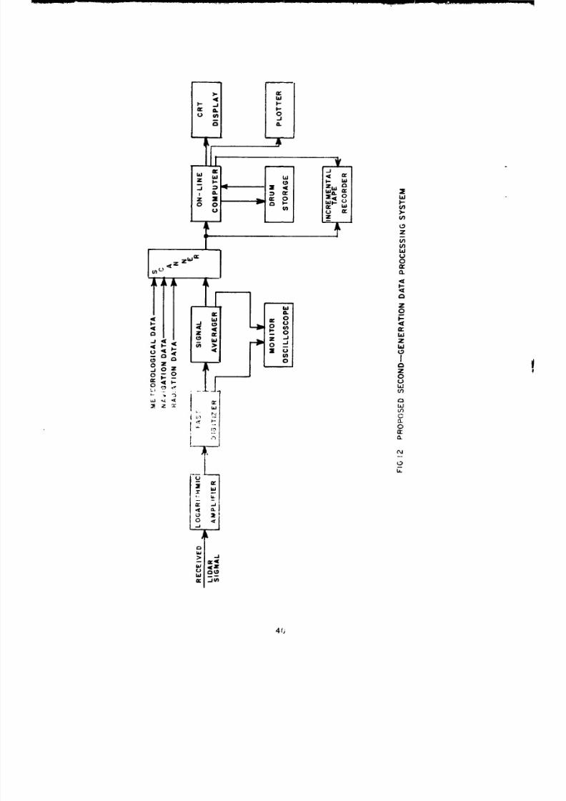
t rack distances ca n either be expressed as negat ive numbers ALONG
t rack or as positive numbers BACKTRACK. Th e Doppler display ha s
provisions fo r coping with rec iproca l t racks that should be exploited
appropriately in this context .
Prov ided that th e cloud remains fair ly well centered in this Doppler
coordinate system an d observational passes ca n be made along the rec-
tangular grid l ines thereof, no changes need be made in the Doppler
set t ing, even if it has drif ted. Prov ided regu la r l andmark identif icat icn
is made to t ie-in th e Doppler coordinates, an d marked into the record ,
e r ro r s ca n be el iminated and the detai led analysis adjusted subsequently
in the same wa y as a t raverse is adjusted in surveying. Unless serious
drif t e r ro r s occur, it would probably be quite satisfactory to work from
th e Doppler coordinates (even if slightly in e r r o r ) in relat ing the cloud
to the ground. Should m o r e prec ise navigation be necessary -- e. g.,
as in control l ing other ai rcraf t with high accuracy -- the necessary ad -
jus tments would have to be calculated by the navigator, with or without
reset t ing of the Doppler. Should the cloud move out of the initial grid
coverage, it would be necessary to r e s e t th e Doppler, or again, if it
became too large fo r the scale used, a scale change would have to be
made.
Th e prec i se detai ls of such a scheme would obviously need furthc..
study in the preparat ion period of an y subsequent operat ion, bu t tho b;.i:
approach appears very straightforward. It should be s t ressed , howe-.,,
that if it is necessary to relate th e l idar-observed cloud posi t ions tc. the
ground or to have a i rcraf t vectored in and around the cloud with great
pr,-cis ion, care m u s t be taken in making an y convers ions necessary fronm
44

8/8/2019 pne 1119 Pre-Gondola 2
http://slidepdf.com/reader/full/pne-1119-pre-gondola-2 52/56
th e l idar (arbi t rary Dopple r ) coordinate system to an y other. Such pro-
cedures would present no difficulty to a profess iona l navigator, however.
Should an ai rcraf t be employed that is no t fitted with Doppler, th e
problem of navigation would be onerous bu t no t insurmountable. Every-
thing would depend upon what other navigational aids are available, and
the skil l of the navigator and pilot team in coordination with the lidar
crew. In principle, the task is s imi lar to that familiar to mil i ta ry ai r
crews in such operations as precision bombing or laying mine pat te rns .
In the absence of Doppler, th e ass is tance of a special system of ground
m a r k s or electronic beacons would be highly desirable. It would be
essent ia l in this case to provide ample t ime fo r developing appropr ia te
techniques and practicing them in f l ight with al l the personnel involved.
E. Communications
P r o b l e m s arose on this tes t in communication between the l idar crew
An d the a ir crew.
in view of the difficulties caused by the noise of the ai rcraf t , it is
recommended that al l intercommunication be tween personnel be carr ied
nu t by te lephone headse ts (of a type designed fo r ai rcraf t in te rcom) .
T-,,o separa te transmitt ing c i rcu i t s could be provided, each recorded
,ti lane in a separa te channel. (The simple stereo audio tape recorder
used on this pro jec t is very suitable fo r this purpose. ) One c i rcu i t would
hi, iqerd fo r l idar operations, the other fo r ai rcraf t operations.
V 'c rophones would be connected accordingly. Facili t ies could be
:-,rovialed fo r switching, if des i red , although it would probably he better
to, have only the l idar d i rec tor capable of speaking into both circuits
s:iv., ' ltaneously (with appropr ia te switch control). Simi la r ar raneements
45

8/8/2019 pne 1119 Pre-Gondola 2
http://slidepdf.com/reader/full/pne-1119-pre-gondola-2 53/56

8/8/2019 pne 1119 Pre-Gondola 2
http://slidepdf.com/reader/full/pne-1119-pre-gondola-2 54/56
REFERENCES
1. M. G. H. Ligda, "The Laser in Meteorology," Discovery (July 1965).
2. R. T. H. Collis, "Lidar: A New Atmospheric Probe," Quart. J. Roy.Meteorol. Soc. Vol. 92, p. 392 (April 1966).
3. C. A. Northend, R. C. Honey, and W. E. Evans, "Laser Radar (Lidar)fo r Meteorological Observation, " Review of Scientific Instruments,Vol. 37. No. 4, pp. 393-400 (April 1966).
4. J. W. Oblanas and R. T. H. Collis, "Lidar Observations of the Pre-GONDOLA I Cloud," Report PNE-l 100, p. 74, Fig. 38 (July 1967).
5. G. N. Webb and R. E. Rogers, "The Contourograph," IEEE Spectrum,pp. 77-87, (June 1966).
47

8/8/2019 pne 1119 Pre-Gondola 2
http://slidepdf.com/reader/full/pne-1119-pre-gondola-2 55/56
APPENDIX
PRE-GONDOLA TECHNICAL REPORTS
Author a n d / o r Tech-
Title of Report Agency nical Program Officer Number
Pre-GONDOLA -
Seismic Site Cali- NC G M. K. Kurtz P N E - I I 0 0bration B. B. Redpath
Site-Selection NCG/Omaha H. A. Jack PNE-1101Investigations W. W. Dudley
Pre-GONDOLA I -Technical Director ' s NC G M. Y. Kurtz et al . P N E - l 102
Summary Report
Genlogic and Engineer-ln'ý Proper t ies NCG/Omaha P. R. F i s h e r et at. PNE-1103Investigations
Close-in Ground WES J. D. Day et al . PNE-1104Motion, Ear thStress , and PorePres su re Measure-mnents
i ' ter r 'edia te Range LR L D V. Power PNE-1105* -r-*Md Motion
9
t ruc tures WES R. F. Pallard PNE- 1106I f s t rvn ien ta t ion
Crater Stu ies: NCG R. W. Harlan PNE-1107Crater Nieasurements P a r t I
Curface MNotion NCG W. G. Chris topher PNE-1107P a r t II
Cioud Development NCG/LFL W. C. Day PNE-1108
Studies R. F. Rohrer
Close-in Displacement AWFL C. J. Lemont PNE-1109Studies
Lidar Observations SRI J. W. Oblanas PNE-1110of P re -GONDOLA I R. T. H. CollisClouds
48

8/8/2019 pne 1119 Pre-Gondola 2
http://slidepdf.com/reader/full/pne-1119-pre-gondola-2 56/56
Pre-GONDOLA I, cont 'd.
Presho t Geophysical LRL-N R. T. Stearns PNE- 1111M e a s u r e m e n t s
Pre-GONDOLA II -Technical Director ' s NCG Wo C. Da y PNE-1112
Sun-nary Repor t W. Y. Kur tz
Close- i r Ground Motion WES J. 0. Da y PNE-l113and Ear th St ress
Enti iueerina Proper t ies NCG P. R. F i s h e r PNE-1114ln 'es t iea t ions W. W. Dudley
A. D. Frandsen
Intermediate Range LR L D. Power PNE- 1115, rcund M otion
Struc tures Ins t ru- WE S R. F. Bal la rd PNE- 1116rnentation
C r a t e r Studies:Crater Measurements NC G R. W. Har lan PNE-1117
;i-d Ejecta Studies M. A. Novak P a r t I
Cr;t t r Studies:(rund Surface Motion NC G J. E. Lat te ry PNE-1117
P a r t II
CiM'd Development NCG W. C. Day PNE- 1118Studies
Ai rhnrne Lidar SRI R. T. Collis PNE-11190)W-ervations J. Oblanas
r, ,-va] of Simulated WES J. D. Da y WES TRPre-ernplaced Charges
C' - ) c - in A ir Blas t BR L J. Keefer BR L TR