pneumatic actuator development for mri robots …electrodes, grippers, sensors, syringes or other...
TRANSCRIPT
Project Number: GSF MQP M101
PNEUMATIC ACTUATOR DEVELOPMENT FOR MRI ROBOTS
A Major Qualifying Project Report
Submitted to the Faculty
of the
WORCESTER POLYTECHNIC INSTITUTE
in partial fulfillment of the requirements for
the Degree of Bachelor of Science
in Mechanical Engineering
Robotics Engineering
Electrical and Computer Engineering
by
__________________________________________________
Michael DiBlasi
__________________________________________________
Andrew Nehring
__________________________________________________
Andrew Smith
Date: 4/ 29/ 2010
Keywords: 1. Pneumatics 2. Hydraulics 3. MRI 4. Robot 5. Stepper motor
Approved:
________________________
Prof. Greg Fischer, Major Advisor
________________________
Prof. Taskin Padir, Co‐Advisor

2
Acknowledgements
We would like to thank the amazing support of the entire WPI community, but a few
groups stand apart in the realization of this project. This project would not have been
possible without them. Professor Greg Fischer and Taskin Padir shared their knowledge,
support and love for the material topics in ways that will last outside the bounds of this
project. The AIM Lab at WPI gave the group materials, funds and work space necessary in
completing the project goals. National Instruments was instrumental in its contribution of
the cRIO Hardware platform as well as the LabVIEW software licenses and system support.
Michael Fagan ’11 committed hours of manufacturing reference and experience as did both
Daniel Jones ‘11 and Daniel Cullen ’10 for electrical and programming support. This project
would not have been possible without the combined efforts of these thoughtful and
knowledgeable individuals and generous contributions of the aforementioned sponsors.

3
Abstract
Magnetic Resonance Imaging (MRI) is an excellent imaging modality for many
conditions, but to date there has been limited success in harnessing this modality for the
guidance of interventional procedures. To aid in the development of interventional devices
for MRI, the modular linear hybrid pneumatic‐hydraulic MRI robot actuator was designed.
It is a modular solution to precision motion in a medical MRI environment. The
implementation of this electronics free, non‐ferrous and nearly completely non‐metallic
linear driver mechanism may be configured to give a clinician the ability to place needles,
electrodes, grippers, sensors, syringes or other medical instruments with an extraordinary
level of flexibility and precision. Its modular design allows for rapid prototyping of robotic
systems and paves the way for more advanced and complex minimally invasive procedures
under real‐time MRI guidance. The team’s design will be used as a platform for future MRI
robot designs and research in collaboration with the UMass Medical School.

4
Table of Contents
ACKNOWLEDGEMENTS 2
ABSTRACT 3
LIST OF FIGURES 6
AUTHORSHIP 7
INTRODUCTION 8
BACKGROUND RESEARCH 10
INTRODUCTION TO MRI 10 MRI APPLICATIONS 13 MRI COMPATIBILITY 15 EXISTING SOLUTIONS 18
METHODOLOGY 24
PROJECT SCOPE 24 DESIGN SPECIFICATIONS 25 QUANTITATIVE 25 QUALITATIVE: 25 DESIGN SPECIFICATIONS DISCUSSION 26 GENERAL DESIGN DECISIONS 28 METHODS 32 OVERALL SYSTEM LAYOUT 32 CONTROLLER 33 PNEUMATIC‐HYDRAULIC SYSTEM 33 ENCODER DESIGN 36 PRELIMINARY DESIGN 37 PUMP 37 DRIVEN PISTON 37 VALVE SYSTEM 38 CONTROL SYSTEM 39 PROTOTYPE DEVELOPMENT 41 MECHANICAL 41 CONTROL SYSTEM 51 FIBER OPTIC DAUGHTERBOARD 53 SENSOR STRIP 57 PROGRAMMING 59

5
VALIDATION 61
ENCODER 61 MECHANICAL DESIGN 61 PROGRAMMING 62
DISCUSSION 64
FUTURE WORKS 65
WORKS CITED 67
APPENDICES 69
CAD MODELS 69 MANUFACTURING DRAWINGS 77 COMPONENT INFORMATION 81 WIRING DIAGRAM 86 LABVIEW 87 PROTOTYPE STEPPER CODE 87 FINAL STEPPER CODE 88 FINAL SUB‐VIS 89 PIC CODE 90 MRIMQP.C 90 MRIMQP.H 92

6
List of Figures Figure 1 – A Modern MRI Machine................................................................................................................. 11 Figure 2 ‐ MRI Sample Images ......................................................................................................................... 11 Figure 3 ‐ Closed MRI ........................................................................................................................................... 13 Figure 4 ‐ Open MRI .............................................................................................................................................. 13 Figure 5 ‐ Sample Distortion ............................................................................................................................. 15 Figure 6 ‐ Actuator Distortion .......................................................................................................................... 16 Figure 7 ‐ Brigham and Women's MRI Robot ............................................................................................ 18 Figure 8 ‐ MrBot Design ...................................................................................................................................... 19 Figure 9 ‐ MrBot application ............................................................................................................................. 20 Figure 10 ‐ Stereotactic Neural Intervention Unit .................................................................................. 21 Figure 11 ‐ Elhawary's Piezoelectric Modular Actuator ....................................................................... 21 Figure 12 ‐ University of Calgary NeuroArm ............................................................................................. 22 Figure 13 ‐ Innomotion Arm ............................................................................................................................. 22 Figure 14 ‐ Decision Matrix ............................................................................................................................... 30 Figure 15 ‐ System Block Diagram ................................................................................................................. 32 Figure 16 ‐ A NI cRIO ........................................................................................................................................... 33 Figure 17 ‐ Prototype Solenoids ..................................................................................................................... 34 Figure 18 ‐ H‐Bridge Circuit .............................................................................................................................. 35 Figure 19 ‐ Prototype Pump ............................................................................................................................. 37 Figure 20 ‐ Prototype Check Valves .............................................................................................................. 38 Figure 21 ‐ Annotated Prototype Picture .................................................................................................... 39 Figure 22 ‐ Final Mechanism CAD .................................................................................................................. 41 Figure 23 ‐ Pump Assembly CAD .................................................................................................................... 42 Figure 24 ‐ Pump Check Valve Circuit .......................................................................................................... 42 Figure 25 ‐ Quad O‐Ring ..................................................................................................................................... 43 Figure 26 ‐ Pump Tube Assembly .................................................................................................................. 44 Figure 27 ‐ Check Valve Design ....................................................................................................................... 46 Figure 28 ‐ H‐Bridge ............................................................................................................................................. 47 Figure 29 ‐ Valve Design ..................................................................................................................................... 47 Figure 30 ‐ Output Manifold ............................................................................................................................. 48 Figure 31 ‐ Driven Piston Design .................................................................................................................... 51 Figure 32 ‐ Fiber Daughterboard .................................................................................................................... 53 Figure 33 ‐ Fiber Assembly ............................................................................................................................... 55 Figure 34 ‐ Encoder Strip ................................................................................................................................... 57 Figure 35 ‐ Magnified Encoder Pattern ........................................................................................................ 58 Figure 36 ‐ Actuator VI ........................................................................................................................................ 59

7
Authorship
ACKNOWLEDGEMENTS MD
ABSTRACT MD
TABLE OF CONTENTS
LIST OF TABLES
LIST OF FIGURES
AUTHORSHIP
INTRODUCTION MD
BACKGROUND RESEARCH MD, AN
METHODOLOGY AN, AS
VALIDATION AN, AS
DISCUSSION AN, AS
FUTURE WORKS MD, AN, AS
WORKS CITED MD, AN
APPENDICES AN. AS
8
Introduction Magnetic resonance imaging (MRI) technology, since its inception in 19721, has
allowed for an incredibly detailed view of the soft in the human body2. MRI scanning is
used as a diagnostic tool for discerning abnormal tissue from healthy for conditions such as
organ infections, tumors and heart complications. Unfortunately due to the intricacies
around human safety and MRI compatibility it still remains largely disconnected from
direct use in guiding medical procedures. Procedural accuracy, repeatability and speed are
fundamental in the field of medicine and can mean the difference between life and death.
Over the years, robots have continued their transition from science fiction and the
surreal into real world applications. MRI compatible robots hold an incredible potential to
revolutionize the medical field and bring MRI scanning technology into the Operating Room
(OR), or rather, bring the OR into the MRI. Robotic surgical assistants, though still a
maturing development, are becoming the next step in robotic assistance as well as human‐
robot interface technologies.3
An MRI compliant surgical robot would enable operators an unprecedented level of
medical unity and could one day even integrate an automated feedback system with the
MRI scanners in real‐time. Research into, and development of precision linear motion
1 Principles of Magnetic Resonance Imaging, Page 2 2 Magnetic Resonance Imaging, Page 1 3 Ergonomic evaluation and guidelines for use of the daVinci Robot System

9
techniques in a medical MRI environment could lead to virtually limitless applications in
the future of medicinal technology.
10
Background Research
Introduction to MRI
NMR (Nuclear Magnetic Resonance) is the condition in which the nuclei of atoms
react to the combination of static and oscillating magnetic fields. This response is used in
order to determine physical, chemical and even biological properties of matter. NMR
spectroscopy scales from one to three‐dimensional analysis depending on the structure
intricacy. While solid state spectroscopy can be appropriately used to determine solid and
liquid structures, dynamic images can also be obtained through similar techniques.4The
name change from NMR to MRI when referring to medical imaging using the technology
comes from the publics’ fear of the word ‘nuclear’ since magnetic resonance is a much less
intimidating name.
The principles of NMR were first characterized in 1946 by Felix Bloch at Stanford
and Edward Mills Purcell of Harvard for fluids and solids respectively. The 1952 Nobel
Prize in Physics went to the pair for introducing the technique that would allow for MRI to
become a reality.5
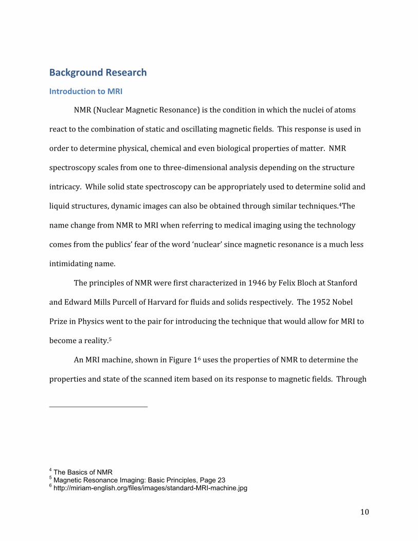
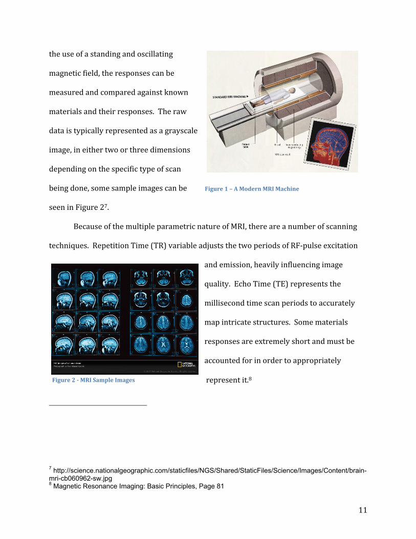
An MRI machine, shown in Figure 16 uses the properties of NMR to determine the
properties and state of the scanned item based on its response to magnetic fields. Through
4 The Basics of NMR 5 Magnetic Resonance Imaging: Basic Principles, Page 23 6 http://miriam-english.org/files/images/standard-MRI-machine.jpg
11
the use of a standing and oscillating
magnetic field, the responses can be
measured and compared against known
materials and their responses. The raw
data is typically represented as a grayscale
image, in either two or three dimensions
depending on the specific type of scan
being done, some sample images can be
seen in Figure 27.
Because of the multiple parametric nature of MRI, there are a number of scanning
techniques. Repetition Time (TR) variable adjusts the two periods of RF‐pulse excitation
and emission, heavily influencing image
quality. Echo Time (TE) represents the
millisecond time scan periods to accurately
map intricate structures. Some materials
responses are extremely short and must be
accounted for in order to appropriately
represent it.8
7 http://science.nationalgeographic.com/staticfiles/NGS/Shared/StaticFiles/Science/Images/Content/brain-mri-cb060962-sw.jpg 8 Magnetic Resonance Imaging: Basic Principles, Page 81
Figure 1 – A Modern MRI Machine
Figure 2 MRI Sample Images

12
A Radio Frequency (RF) pulse is another name for the oscillating electric field that is
used to excite the protons in hydrogen atoms and cause them to resonate. This pulse is
enabled on the microsecond scale, and is generated in conjunction with time varying
magnetic fields that are considerably weaker than the static magnetic field and used for
slice location selection and image construction.9
When putting objects in or near the MRI scanner, a magnetic field may be created by
an electric current running through a strand or coil of wire that can disrupt the scanners
field. Similarly, it is affected by metallic conductors that induce eddy currents and ferrous
materials that directly distort the field. The resulting influences from the metallic objects
in the scanner bore alter the magnetic field (Field Homogeneity) which will profoundly
distort the received image.10 These factors are covered in‐depth in the MRI Compatibility
section.
9 Principles of Magnetic Resonance Imaging, Page 70 10 Essentials of Electromagnetics for Engineering, Page 271
13
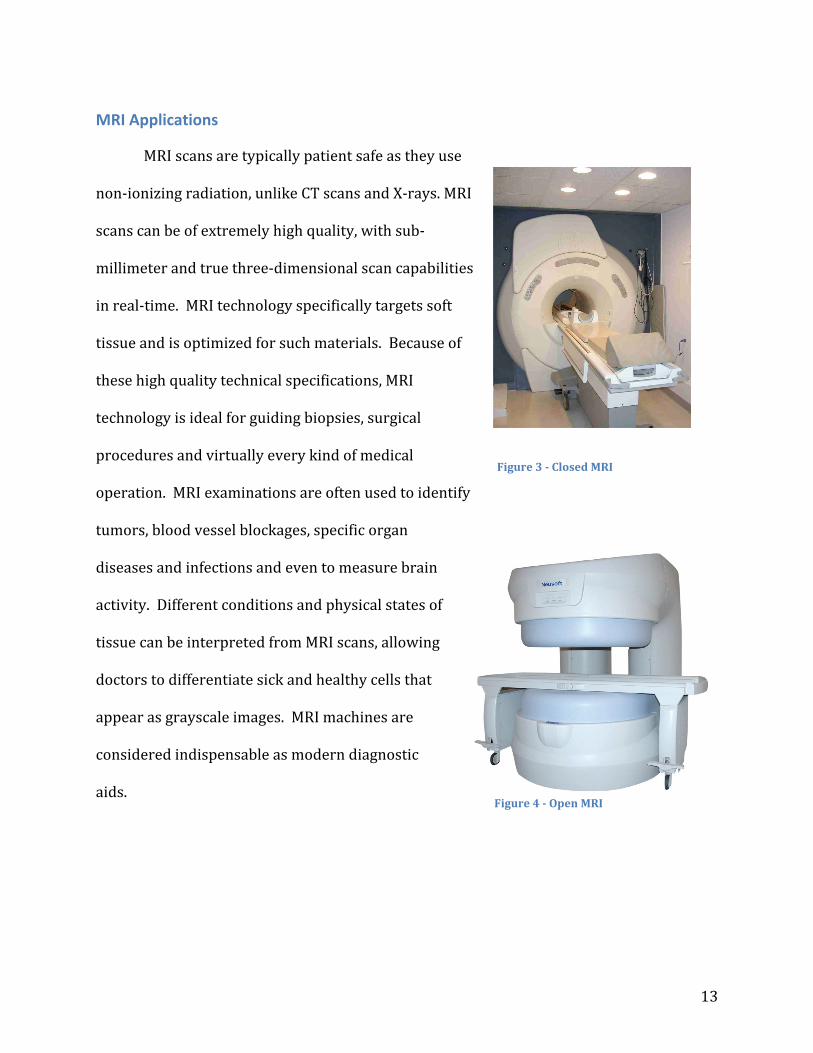
MRI Applications
MRI scans are typically patient safe as they use
non‐ionizing radiation, unlike CT scans and X‐rays. MRI
scans can be of extremely high quality, with sub‐
millimeter and true three‐dimensional scan capabilities
in real‐time. MRI technology specifically targets soft
tissue and is optimized for such materials. Because of
these high quality technical specifications, MRI
technology is ideal for guiding biopsies, surgical
procedures and virtually every kind of medical
operation. MRI examinations are often used to identify
tumors, blood vessel blockages, specific organ
diseases and infections and even to measure brain
activity. Different conditions and physical states of
tissue can be interpreted from MRI scans, allowing
doctors to differentiate sick and healthy cells that
appear as grayscale images. MRI machines are
considered indispensable as modern diagnostic
aids.
Figure 3 Closed MRI
Figure 4 Open MRI

14
There are two main types of MRI machines used in hospitals. A traditional high‐field
closed MRI machine, shown in Figure 311, has more accurate imaging capabilities but is
more constrained for affecting patient access and can cause claustrophobia. In the closed
machine the magnetic coil goes completely around the patient, which is that cause for the
more accurate yet tighter scanning areas. Physicians tend to use the closed model for the
accuracy benefits. An open MRI, shown in Figure 412, has, as the name implies, a more open
and larger work area but does not have as accurate imaging as the closed type due to the
lower field strengths and poorer magnetic field homogeneity. The open style typically
allows for heavier patients (up to 450 pounds).
A relatively new style of MRI equipment is a standing model. This hardware permits
physicians to examine patients in the standing position allowing for the view of weight
bearing forces.13 It may be more accurate in scanning for spinal conditions but result in
more pain for the patient, assuming they can get into the required position at all. As with
the open scanner, field strength is weaker and these scanners are usually restricted in their
ability to do general imaging of the body.
Since open MRIs are less common and provide lower quality images, the focus of our
work is on developing a system that will enable the use of readily available diagnostic
scanners to help guide interventional procedures.
11 http://www.rajabgroup.com/Images/Superstar%200.35T%20Open%20MRI%20n.JPG 12 http://www.mritoday.net/MRI2.JPG 13 Open Stand-Up MRI: A New Instrument for Positional Neuroimaging

15
MRI Compatibility
Image artifacts come from a number of sources, including noise from wiring
entering the scanner room, unstable power supplies and uncalibrated hardware, and also
from distortion due to metals or ferrous materials. In addition to the obvious safety
concerns, ferrous materials can cause inhomogeneities in the scanning magnetic field.
Random RF noise causes static‐like artifacts in the images, samples of which are shown in
Figure 5.
The important types of MRI interference include distortion and noise. Distortion
interference is the condition where the image is stretched or distorted, or may present
itself as large signal voids in the image. Electrical noise in the system creates static in the
image, much like bad reception on an
analog TV and stems from the
scanner’s receiver antenna picking up
stray signals during imaging. Analog
signals with jumps or spikes in the
waveform are an example of this kind
of electrical noise. These types of
interference can prove to be
extremely problematic in such a
precise and delicate operation and if
not appropriately considered and dealt Figure 5 Sample Distortion
16
with, they can cause problems such as false diagnoses.
Pacemakers, dental implants and orthopedic hardware such as screws and plates
cause severe interference in MRI scans that may range from a small signal void to image
distortion to a major safety hazard. Future iterations of these products are striving for MRI
compatibility. Patients with these conditions are often strongly recommended to try other
imaging techniques as besides interfering with the machinery, the items can malfunction or
overheat.
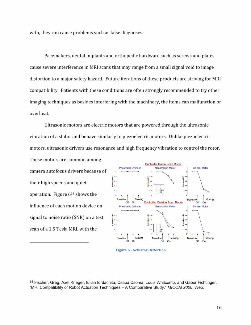
Ultrasonic motors are electric motors that are powered through the ultrasonic
vibration of a stator and behave similarly to piezoelectric motors. Unlike piezoelectric
motors, ultrasonic drivers use resonance and high frequency vibration to control the rotor.
These motors are common among
camera autofocus drivers because of
their high speeds and quiet
operation. Figure 614 shows the
influence of each motion device on
signal to noise ratio (SNR) on a test
scan of a 1.5 Tesla MRI, with the
14 Fischer, Greg, Axel Krieger, Iulian Iordachita, Csaba Csoma, Louis Whitcomb, and Gabor Fichtinger. "MRI Compatibility of Robot Actuation Techniques – A Comparative Study." MICCAI 2008. Web.
Figure 6 Actuator Distortion

17
controller both inside and outside of the scanning room. When compared with a pneumatic
cylinder, pneumatics had no visible effect on the SNR even when running, while the
piezoelectric motor (Nanomotion motor) had a small decrease in SNR under rest, but
considerable negative effect on the noise levels when enabled. The ultrasonic motor
(Shinsei motor) produced no change in SNR until it was turned on, where it caused the
most significant drop in the ratio level. In terms of minimizing noise in the image,
pneumatic controllers and drivers are the most effective.
Piezoelectric motors can be used in MRI environments if they are designed
appropriately and not run simultaneously with the scanning equipment.15 Piezoelectric
motors are driven through the use of an electric field, translating ultrasonic vibrations into
linear or rotary motion. Ceramic drivers allow these particular motors to cater to the
material constraints of the MRI environment but the inclusion of electric field control
forces the device to remain off during scans.
Strong electric currents and metals can cause interference with the magnetic fields
of the machine, resulting in noise in the imaging or even damaged equipment from
attracted materials. Metals with even small amounts of ferromagnetic elements can cause
trouble in a magnetic field the size of an MRI machine. All metals are conductive and will
cause an effect on the image to some degree but particular types and shapes can cause
much more damage. 15 Implantable linear motor is made of piezoceramics for MRI
18
Existing Solutions
The medical environment is the perfect place for robotic applications because of the
high levels of precision and repeatability. The benefits of such robotically controlled and
assisted systems continue to grow daily. The daVinci surgical robot16 is the most popular
surgical robot on the market today. The daVinci is capable of assisting surgeons in
laparoscopic procedures with a wide array of benefits. Robots by nature are more precise
and repeatable than humans and allow for corrective software and optimized hardware to
go above and beyond what humans alone can achieve. The miniaturization of tooling, 3‐
dimensional cameras and increased dexterity allow for many secondary benefits. Less
blood loss from smaller wounds means shorter healing times and less pain and scarring as
well as decreased chances of complications.
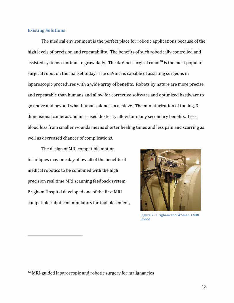
The design of MRI compatible motion
techniques may one day allow all of the benefits of
medical robotics to be combined with the high
precision real time MRI scanning feedback system.
Brigham Hospital developed one of the first MRI
compatible robotic manipulators for tool placement,
16 MRI‐guided laparoscopic and robotic surgery for malignancies
Figure 7 Brigham and Women's MRI Robot

19
shown in Figure 717. It was specifically designed to hold a catheter to assist a surgeon.
Although physically possible to insert the catheter, it was deemed ethical and legally
dangerous. This device acts as a simple proof of concept of MRI compatible robots and a
stepping stone for more advanced systems.
MrBot, shown in Figure 8, was
developed by the Johns Hopkins
Urology Robotics Lab in April of 2007
for MRI‐guided biopsies18. The device
was designed entirely of ceramic, plastic
and rubber and obtains 5 degrees‐of‐
freedom from six pneumatic drivers and
a gear set as a driving force. The developers claim to have smooth motion in steps as small
as 50 micrometers, but overall needle tip precision of 1 millimeter in 3d space.
Since typical MRI machines have a resolution of up to 0.1 millimeters in diagnostic
imaging, this device could benefit from an increase in its own precision. The pneumatic
drivers operate directly from the pressurized air line from the control system and can
achieve steps as small as 0.55 millimeters19. By regulating the pneumatic pressure on
17 Surgical assist robot for the active navigation in the intraoperative MRI: Hardware design issues 18 Magnetic Resonance Imaging Compatible Robotic System for Fully Automated Brachytherapy Seed Placement 19 Motion control of pneumatic drives
Figure 8 MrBot Design

20
either side of the cylinder it can achieve motion and locking functionality. Because they are
directly driven by hospital provided air they lack the necessary forces and reliability that
would be required for a procedure to be carried out safely on a patient. Since air regulators
can be unreliable the system could fail due to a brown‐out or fluctuation in air pressure.
Although MRI compatibility is a very important aspect of these robotic devices safety still
comes first. Besides the plunger itself, the system contains no linear sliders, instead using
the pneumatic cylinders as joints for the system in general. Because of the way the system
handles motion, it is based around a central point and has a very limited adjustment range.
The device is quite large relative to the patient platform bed, forcing the user onto
their side, as seen in Figure 9. Patients tend to lie on their backs during MRI procedures
and standard operations because of organ shift. Organ placement becomes unpredictable
in other orientations which make surgeries and scanning techniques difficult if not
impossible. MRI scans sometimes
take over 15 minutes to complete, and
optimal images require the patient to
stay nearly perfectly still. Patients are
often lightly restrained to help reduce
shift but laying on their side
introduces a new set of complexities
in ergonomics and comfort.
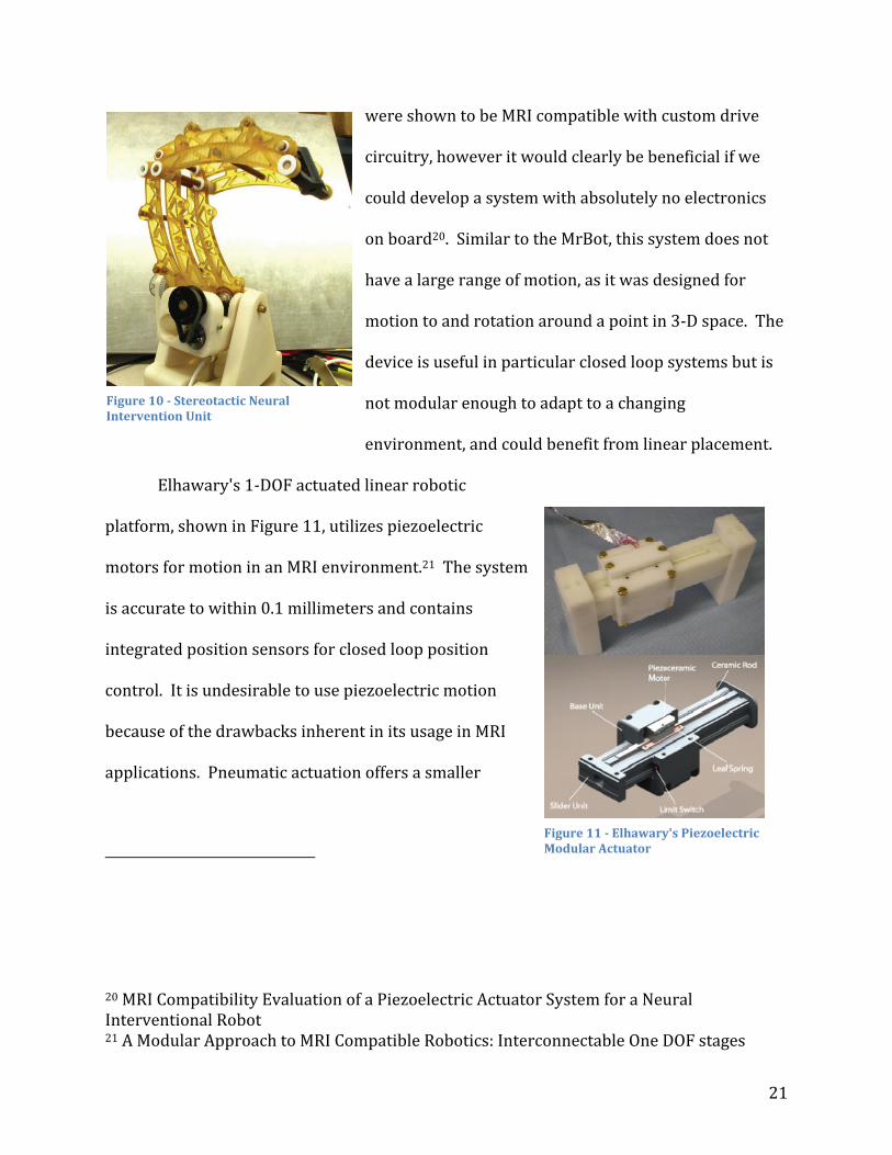
The Stereotactic Neural Intervention Unit, shown in Figure 10, was designed by the
AIM Lab at WPI in 2009 and allows for the accurate placement of a needle and rotation
around the specified point using linkages. The system uses piezoelectric motors which
Figure 9 MrBot application
21
were shown to be MRI compatible with custom drive
circuitry, however it would clearly be beneficial if we
could develop a system with absolutely no electronics
on board20. Similar to the MrBot, this system does not
have a large range of motion, as it was designed for
motion to and rotation around a point in 3‐D space. The
device is useful in particular closed loop systems but is
not modular enough to adapt to a changing
environment, and could benefit from linear placement.
Elhawary's 1‐DOF actuated linear robotic
platform, shown in Figure 11, utilizes piezoelectric
motors for motion in an MRI environment.21 The system
is accurate to within 0.1 millimeters and contains
integrated position sensors for closed loop position
control. It is undesirable to use piezoelectric motion
because of the drawbacks inherent in its usage in MRI
applications. Pneumatic actuation offers a smaller
20 MRI Compatibility Evaluation of a Piezoelectric Actuator System for a Neural Interventional Robot 21 A Modular Approach to MRI Compatible Robotics: Interconnectable One DOF stages
Figure 10 Stereotactic Neural Intervention Unit
Figure 11 Elhawary's Piezoelectric Modular Actuator
22
impact on image quality than all other MRI compatible motion systems in use today.
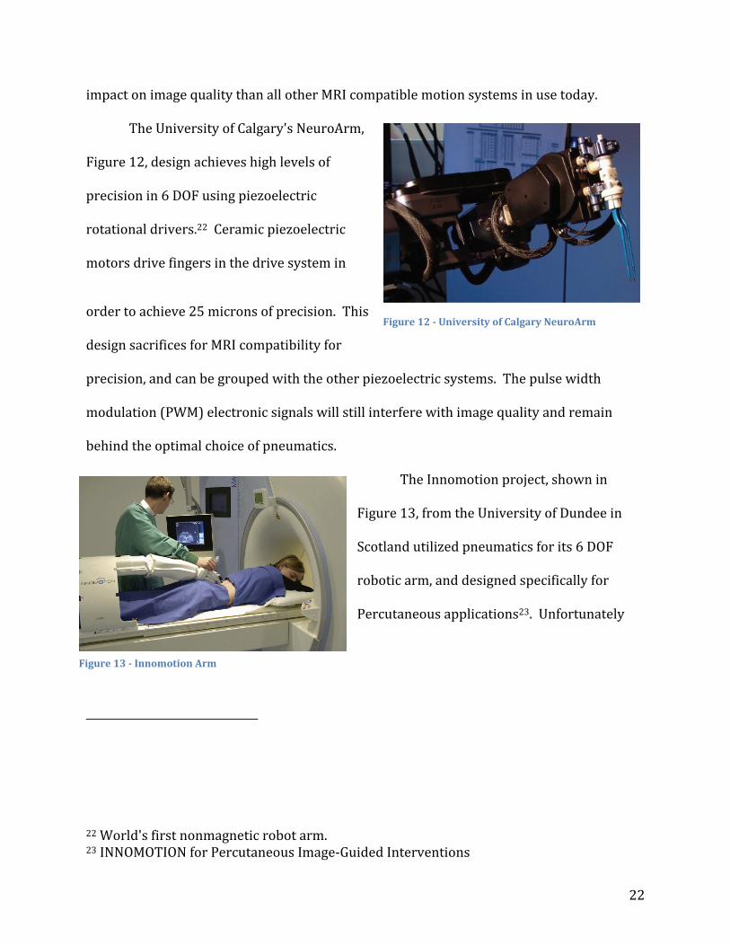
The University of Calgary's NeuroArm,
Figure 12, design achieves high levels of
precision in 6 DOF using piezoelectric
rotational drivers.22 Ceramic piezoelectric
motors drive fingers in the drive system in
order to achieve 25 microns of precision. This
design sacrifices for MRI compatibility for
precision, and can be grouped with the other piezoelectric systems. The pulse width
modulation (PWM) electronic signals will still interfere with image quality and remain
behind the optimal choice of pneumatics.
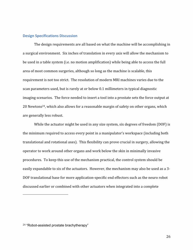
The Innomotion project, shown in
Figure 13, from the University of Dundee in
Scotland utilized pneumatics for its 6 DOF
robotic arm, and designed specifically for
Percutaneous applications23. Unfortunately
22 World's first nonmagnetic robot arm. 23 INNOMOTION for Percutaneous Image‐Guided Interventions
Figure 12 University of Calgary NeuroArm
Figure 13 Innomotion Arm

23
the system is not particularly precise, deviating up to 1 millimeter from the targeted area.
Although pneumatics are able to operate within an MRI machine without compromising
the readings it is another challenge to create the system to be accurate and repeatable
enough for medical use.
Comparing the types of motion and their effects on image quality makes it clear that
a pneumatics based system is the optimal solution. Combining the modularity and closed
control feedback of the linear actuators with the precision of the pneumatic stepper design
should allow for surgical quality motion without sacrificing MRI scan quality. By
integrating the systems into a single, solid design the base for an MRI general service or
even surgical robot can come to fruition.

24
Methodology
Project Scope
The background research into this project showed two major problems to
overcome. To begin with, servo controlled pneumatically controlled systems don’t reliably
run with ththe nevessary resolution. Most pneumatic systems are fully extended or fully
retracted, with a couple of patents and production models capable of a centered position as
well. Attempts at servo controlled pneumatics often are only successful in well modeled,
static environments and do not adapt well to the changing environment or load that would
be present in a medical application. The over 1000 steps needed for this mechanism would
be a huge step forward in pneumatic technology.
While this problem would certainly be challenge enough, the finished product also
needed to be MRI‐compatible. Discussed in more detail in the background section, this
essentially means that there can be no ferrous metals whatsoever, no large pieces of any
conductive material, and no electrical components. With this severe restriction imposed on
the complexity of solving the resolution problem inherent in pneumatic systems, the
possible solutions are very limited.
These actuators will be used to create multiple degree of freedom systems,
sometimes with different requirements for each axis of motion. As such, the actuators
should be designed to be modular for internally and externally. The system should be able
to be modified to give different output characteristics such as force and travel, while
keeping the form factor small enough and standardized to allow for multiple actuators to
be stacked to create complex systems.

25
Design Specifications
Quantitative
Minimum of 15.3 centimeters (6 inches) of end-to-end travel
Uniquely measurable 0.1 millimeter (0.004 inch) mechanical steps
At least 20 Newtons (4.5 pound-force) output
End-to-end travel in 15 seconds
Control system must be able to run six actuators
Qualitative:
Mechanism must be able to lock, and the fail-safe state should do so automatically if
a pressure loss occurs.
Manual mode should be included to allow the operator to slide the mechanism to the
proper location. Step increments must resume without jumps.
Compact size.
Easy to interface with duplicates to create multiple degree of freedom machines.
Full MRI-Compatibility:
o No ferrous metals
o No large conductive parts, MRI Machine image should not be noticeably
distorted
o No on-board electronics for drive and sensing.
Cable running from machine should be small and robust carry only air lines and fiber
optic cables.
Mechanism’s motions to create forward and backward steps should be unique to
ensure predictable output.
Mechanism must be scalable in force, range, and step size.
System must be closed loop, with integrated joint position sensing.
26
Design Specifications Discussion
The design requirements are all based on what the machine will be accomplishing in
a surgical environment. Six inches of translation in every axis will allow the mechanism to
be used in a table system (i.e. no motion amplification) while being able to access the full
area of most common surgeries, although so long as the machine is scalable, this
requirement is not too strict. The resolution of modern MRI machines varies due to the
scan parameters used, but is rarely at or below 0.1 millimeters in typical diagnostic
imaging scenarios. The force needed to insert a tool into a prostate sets the force output at
20 Newtons24, which also allows for a reasonable margin of safety on other organs, which
are generally less robust.
While the actuator might be used in any size system, six degrees of freedom (DOF) is
the minimum required to access every point in a manipulator’s workspace (including both
translational and rotational axes). This flexibility can prove crucial in surgery, allowing the
operator to work around other organs and work below the skin in minimally invasive
procedures. To keep this use of the mechanism practical, the control system should be
easily expandable to six of the actuators. However, the mechanism may also be used as a 3‐
DOF translational base for more application‐specific end effectors such as the neuro robot
discussed earlier or combined with other actuators when integrated into a complete
24 “Robot-assisted prostate brachytherapy”

27
system. The final quantitative requirement is the 15 second end‐to‐end travel time. Since
rapid motions are not required, and in fact undesirable, in surgery, this was chosen as a
reasonable time to traverse the full range of motion. This also makes it the least critical of
the quantitative requirements, while the resolution and accuracy of the machine are by far
the most important.
Several of the qualitative requirements are based in safety. For example, should a
pressure loss occur, the driving mechanism of the system could become unpredictable, or
simply stop providing an input to the system. In this case, whatever is being used on the
end of the manipulator could drop or move on its own, possibly with severe repercussions
during surgery. To prevent this, the system must be designed so that the fail‐safe state is to
lock and prevent motion without manual intervention in the event of a system pressure
loss.
Working in an MRI environment also places severe conditions on the design of any
mechanism. As discussed in the background, this means that no ferrous metals can be used
in the design, and neither can any large pieces of a conductive material. Ferrous metals
would be turned into projectiles by the powerful magnetic fields inside of the MRI, and
conductive materials would have current induced in them, which would warp the image
generated by the MRI. Both of these, especially the former, cannot be allowed to occur.
28
General Design Decisions
The first step in created the actuator was to choose a basic concept. The only
precedent for a pneumatic stepping actuator in an MRI environment was the motor
included in the MrBOT from Johns Hopkins25, but this was a bulky, inaccurate mechanism
based rotary harmonic motion, which is too fragile for the scale and accuracy that needed
in this new mechanism. There is also the modular linear stepping actuator from the
Imperial College London26, but this uses piezoelectric actuators to provide the motion, and
removing all electronic components from the machine would be highly desirable. The
design developed in this project is a pneumatic‐hydraulic hybrid actuator, an improvement
on current technology in its accuracy and force capabilities, as well as being simpler and
capable of being far more compact.
At the beginning of the project work there were many different concepts for how to
proceed. To determine the final design choice, a design matrix was used as it is described
below.
The first design, presented by Professor Fischer, consisted of several actuated
fingers and a rack gear used to create a linear harmonic motor. This worked by having the
finger spacing offset from the pitch of the rack gear, so that as the fingers fire in order, the
25 Magnetic Resonance Imaging Compatible Robotic System for Fully Automated Brachytherapy Seed Placement 26 A Modular Approach to MRI Compatible Robotics: Interconnectable One DOF stages

29
rack gear would progress slowly forward. In this way, a large, inaccurate motion could be
converted a movement of the precision needed for the final mechanism.
The next design considered used pneumatic pistons to turn a crankshaft, in precise
angular displacements. A gear train would be used to reduce these angular displacements,
before finally advancing a rack gear by that precise motion. There was a major flaw in this
design however, with plastic gears and plastic mountings, there would be a substantial
amount of backlash in the system. This is highly undesirable in this system, as any slop in
the mechanism could have serious repercussions in a surgical environment.
A linkage driven solution was also considered. Although the details of this method
were never fully worked out, the concept consisted of using pneumatics to turn the crank of
a four‐bar linkage. This, in turn, would move into a rack gear, engage, and move it forward
similar to the method of the finger walking mechanism. However, by tweaking the linkage,
much higher efficiencies can be achieved.
Kevin Harrington presented another solution using a mechanism similar to a watch
escapement. By applying pressure to an output, a rotational mass‐spring system could be
used to only allow forward motion in precisely timed steps. By carefully monitoring the
time and turning the pressure off at the right time, a precise motion could be achieved.
The final design option was presented by Greg Cole. This system is a pneumatic‐
hydraulic hybrid system, where pneumatic valves and a pneumatic pump control the
motion of hydraulic fluid, which is used to give the precision needed at the final output. If
the volumes could be worked out to have one pump motion move the output stage by the
desired resolution, system control would be very simple.
30
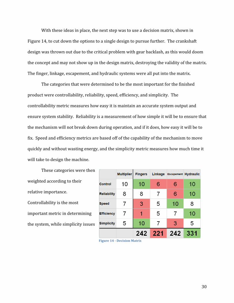
With these ideas in place, the next step was to use a decision matrix, shown in
Figure 14, to cut down the options to a single design to pursue further. The crankshaft
design was thrown out due to the critical problem with gear backlash, as this would doom
the concept and may not show up in the design matrix, destroying the validity of the matrix.
The finger, linkage, escapement, and hydraulic systems were all put into the matrix.
The categories that were determined to be the most important for the finished
product were controllability, reliability, speed, efficiency, and simplicity. The
controllability metric measures how easy it is maintain an accurate system output and
ensure system stability. Reliability is a measurement of how simple it will be to ensure that
the mechanism will not break down during operation, and if it does, how easy it will be to
fix. Speed and efficiency metrics are based off of the capability of the mechanism to move
quickly and without wasting energy, and the simplicity metric measures how much time it
will take to design the machine.
These categories were then
weighted according to their
relative importance.
Controllability is the most
important metric in determining
the system, while simplicity issues
Figure 14 Decision Matrix

31
can be overcome. Reliability, speed, and efficiency are all approximately the same, as these
too can be overcome with proper design, although this is a more challenging problem to
overcome with detailed design.
The different designs were then reviewed with special attention paid to the qualities
that were considered important for the project. Each design was assigned a value between
1 and 10 in each category. The sum of these values, taking into account their respective
multipliers, sum to find the designs’ totals, the highest of which signifies the best option.
Based off of the decision matrix arrived at during brainstorming, the hydraulic hybrid
design is the best option.
32
Methods
Overall System Layout
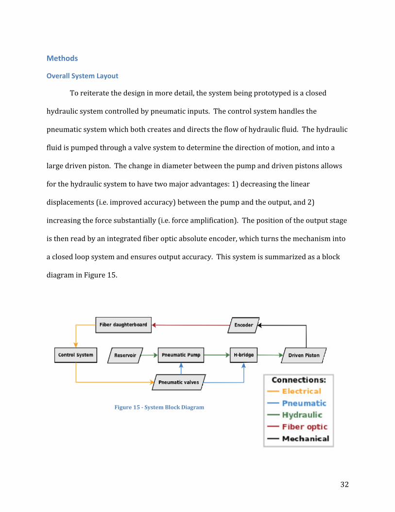
To reiterate the design in more detail, the system being prototyped is a closed
hydraulic system controlled by pneumatic inputs. The control system handles the
pneumatic system which both creates and directs the flow of hydraulic fluid. The hydraulic
fluid is pumped through a valve system to determine the direction of motion, and into a
large driven piston. The change in diameter between the pump and driven pistons allows
for the hydraulic system to have two major advantages: 1) decreasing the linear
displacements (i.e. improved accuracy) between the pump and the output, and 2)
increasing the force substantially (i.e. force amplification). The position of the output stage
is then read by an integrated fiber optic absolute encoder, which turns the mechanism into
a closed loop system and ensures output accuracy. This system is summarized as a block
diagram in Figure 15.
Figure 15 System Block Diagram

33
Controller
The controller for the system will
be the National Instruments (NI)
CompactRIO, shown in Figure 16. This
consists of a chassis module containing
the main processor, as well as a Field‐
Programmable Gate Array (FPGA) to
handle signal processing from the input/output modules. The chassis can hold up to eight
of these modules, and there is a wide range of options for these. For this application, digital
I/O, both high power (pneumatic solenoids) and low power (digital signals) are the most
critical, although analog sensors may be added in the future. For these reasons, the chassis
was equipped with a mix of digital and analog I/O modules. This high level of modularity is
an excellent fit for this application, allowing the end user to adjust the mix of modules to fit
even more modules, or add more analog sensor capabilities.
The NI CompactRIO is also designed to operate with NI LabVIEW, a graphical
programming language. This language is designed to create a graphical user interface
(GUI) with hardware interaction provided by a block diagram program running in the
background. As a simple GUI would be a great asset for allowing users with minimal
technical training to operate the actuator, this is another excellent asset for the project.
Pneumatic‐Hydraulic System
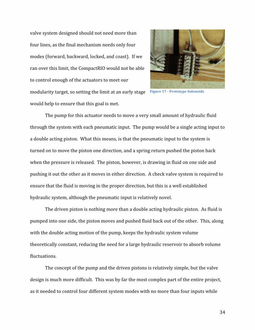
The NI CompactRIO is connected to an array of six pneumatic valves, shown in
Figure 17. This would provide plenty of independent channels for whatever valve system
was designed, although the number of channels needed should be substantially fewer. Any
Figure 16 A NI cRIO
34
valve system designed should not need more than
four lines, as the final mechanism needs only four
modes (forward, backward, locked, and coast). If we
ran over this limit, the CompactRIO would not be able
to control enough of the actuators to meet our
modularity target, so setting the limit at an early stage
would help to ensure that this goal is met.
The pump for this actuator needs to move a very small amount of hydraulic fluid
through the system with each pneumatic input. The pump would be a single acting input to
a double acting piston. What this means, is that the pneumatic input to the system is
turned on to move the piston one direction, and a spring return pushed the piston back
when the pressure is released. The piston, however, is drawing in fluid on one side and
pushing it out the other as it moves in either direction. A check valve system is required to
ensure that the fluid is moving in the proper direction, but this is a well established
hydraulic system, although the pneumatic input is relatively novel.
The driven piston is nothing more than a double acting hydraulic piston. As fluid is
pumped into one side, the piston moves and pushed fluid back out of the other. This, along
with the double acting motion of the pump, keeps the hydraulic system volume
theoretically constant, reducing the need for a large hydraulic reservoir to absorb volume
fluctuations.
The concept of the pump and the driven pistons is relatively simple, but the valve
design is much more difficult. This was by far the most complex part of the entire project,
as it needed to control four different system modes with no more than four inputs while
Figure 17 Prototype Solenoids
35
remaining compact. This sort of system is generally done in hydraulics by using a multiple
position manual switch, which the operator will put into whatever mode they need.
Automatically controlled hydraulics rarely use more than off/on control, or simply switch
which side of a system the pressure is being applied to, and allow the low pressure fluid to
find its way back to the reservoir through uncontrolled paths. This was completely
unacceptable in this situation, as locking and coasting modes were needed as well, and
there was no simple way to create a four position pneumatic to control a multiple position
switch.
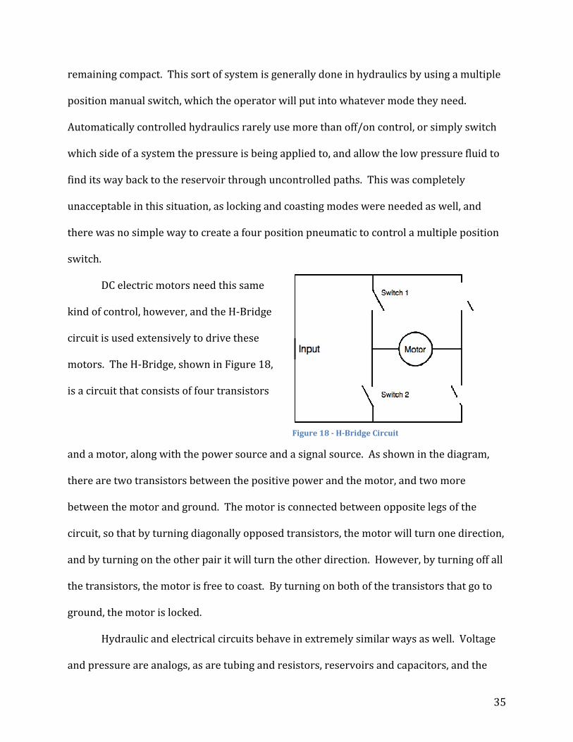
DC electric motors need this same
kind of control, however, and the H‐Bridge
circuit is used extensively to drive these
motors. The H‐Bridge, shown in Figure 18,
is a circuit that consists of four transistors
and a motor, along with the power source and a signal source. As shown in the diagram,
there are two transistors between the positive power and the motor, and two more
between the motor and ground. The motor is connected between opposite legs of the
circuit, so that by turning diagonally opposed transistors, the motor will turn one direction,
and by turning on the other pair it will turn the other direction. However, by turning off all
the transistors, the motor is free to coast. By turning on both of the transistors that go to
ground, the motor is locked.
Hydraulic and electrical circuits behave in extremely similar ways as well. Voltage
and pressure are analogs, as are tubing and resistors, reservoirs and capacitors, and the
Figure 18 HBridge Circuit
36
like. By converting this well established electrical circuit to its hydraulic analog, a valve
system can be made that only required two inputs to switch between the four modes of
operation. There are some changes in just how the system behaves though. In the
electrical version, turning on all of the transistors would short out the voltage source, but
turning on all of the valves in a hydraulic system is perfectly acceptable. Using the H‐
Bridge vastly simplifies the system, and allows for even more mechanisms to be run from a
single CompactRIO. To the best of our knowledge, this type of hydraulic control system has
not been developed before, so finding out if an H‐Bridge could give us the desired fluid
outputs was critical.
Encoder Design
The system needs to have an accurate feedback mechanism to ensure that any
position errors are known by the controller. This could work either by finding a home
position and keeping track of how far the system has traveled from it, or by keeping track
of an absolute position. However, it would be far simpler for the system to pick up its
operation after being manually positioned by the operator if it was using the absolute
position method.
As no electronics can be used inside of the MRI, the encoder had to use fiber optics
instead. The sensor would also need 12 bits to get the resolution needed with the travel
that is also required. The array of 12 fibers would be arranged to read in the pattern
printed on a sensor strip, which provides the exact location of the system output.
37
Preliminary Design
The first development stage of the project focused on developing a prototype proof‐
of‐concept evaluation version of the mechanism without being concerned for clinical
feasibility or MRI‐Compatibility. Creating something almost entirely made from plastic
with the machining capabilities on the WPI campus (primarily meant for metals) takes far
more time and effort than using whatever material is convenient at the time. This design
iteration would not be miniaturized either; its sole purpose is to test the basic concept of a
pneumatic‐hydraulic hybrid stepping actuator.
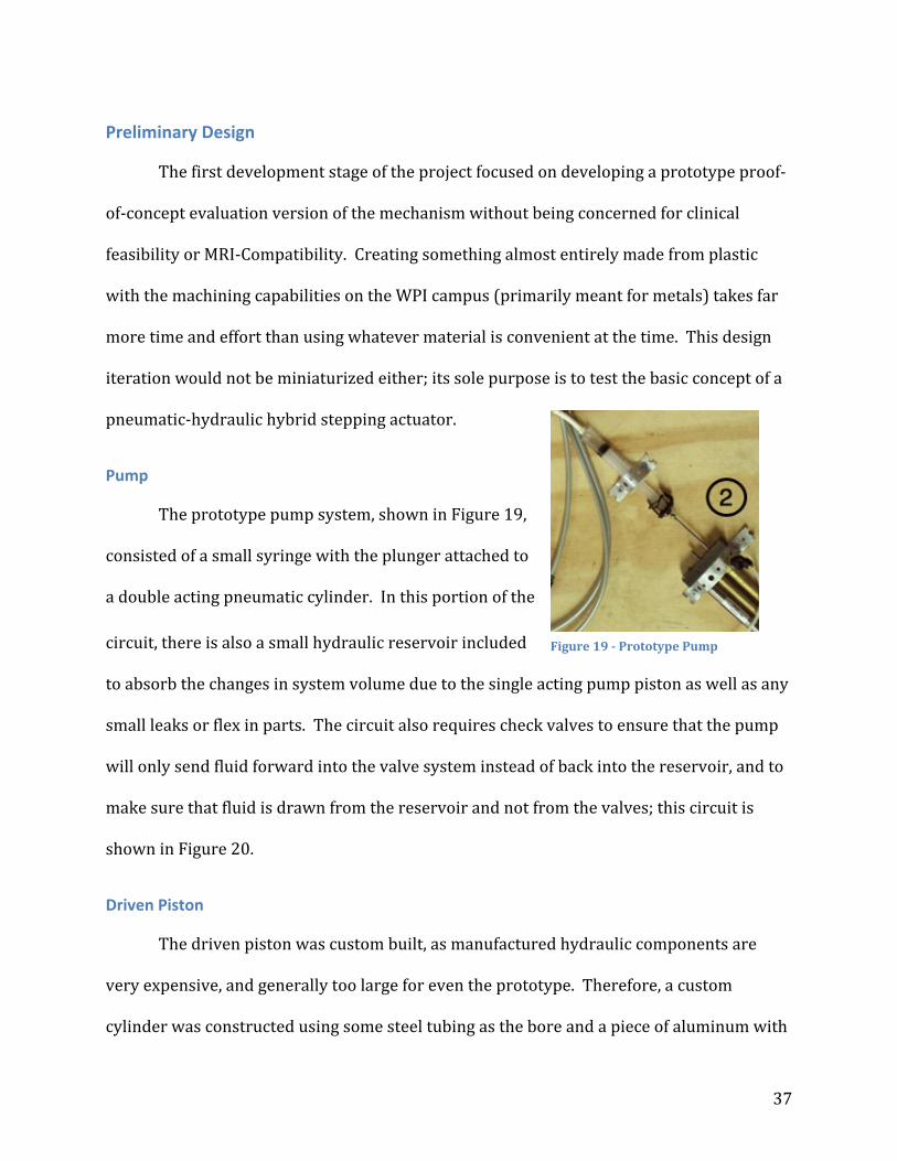
Pump
The prototype pump system, shown in Figure 19,
consisted of a small syringe with the plunger attached to
a double acting pneumatic cylinder. In this portion of the
circuit, there is also a small hydraulic reservoir included
to absorb the changes in system volume due to the single acting pump piston as well as any
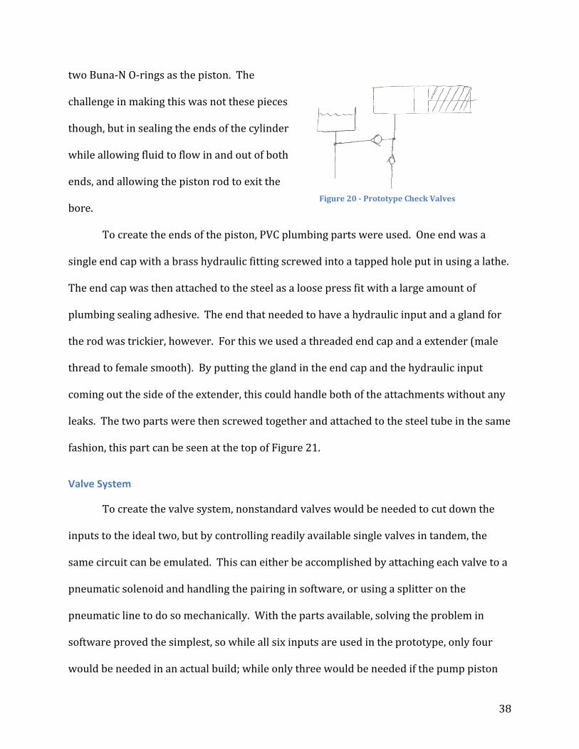
small leaks or flex in parts. The circuit also requires check valves to ensure that the pump
will only send fluid forward into the valve system instead of back into the reservoir, and to
make sure that fluid is drawn from the reservoir and not from the valves; this circuit is
shown in Figure 20.
Driven Piston
The driven piston was custom built, as manufactured hydraulic components are
very expensive, and generally too large for even the prototype. Therefore, a custom
cylinder was constructed using some steel tubing as the bore and a piece of aluminum with
Figure 19 Prototype Pump
38
two Buna‐N O‐rings as the piston. The
challenge in making this was not these pieces
though, but in sealing the ends of the cylinder
while allowing fluid to flow in and out of both
ends, and allowing the piston rod to exit the
bore.
To create the ends of the piston, PVC plumbing parts were used. One end was a
single end cap with a brass hydraulic fitting screwed into a tapped hole put in using a lathe.
The end cap was then attached to the steel as a loose press fit with a large amount of
plumbing sealing adhesive. The end that needed to have a hydraulic input and a gland for
the rod was trickier, however. For this we used a threaded end cap and a extender (male
thread to female smooth). By putting the gland in the end cap and the hydraulic input
coming out the side of the extender, this could handle both of the attachments without any
leaks. The two parts were then screwed together and attached to the steel tube in the same
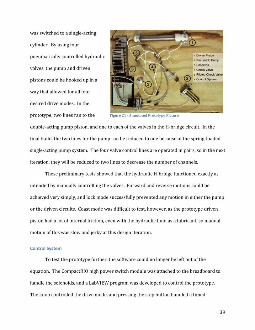
fashion, this part can be seen at the top of Figure 21.
Valve System
To create the valve system, nonstandard valves would be needed to cut down the
inputs to the ideal two, but by controlling readily available single valves in tandem, the
same circuit can be emulated. This can either be accomplished by attaching each valve to a
pneumatic solenoid and handling the pairing in software, or using a splitter on the
pneumatic line to do so mechanically. With the parts available, solving the problem in
software proved the simplest, so while all six inputs are used in the prototype, only four
would be needed in an actual build; while only three would be needed if the pump piston
Figure 20 Prototype Check Valves
39
was switched to a single‐acting
cylinder. By using four
pneumatically controlled hydraulic
valves, the pump and driven
pistons could be hooked up in a
way that allowed for all four
desired drive modes. In the
prototype, two lines ran to the
double‐acting pump piston, and one to each of the valves in the H‐bridge circuit. In the
final build, the two lines for the pump can be reduced to one because of the spring‐loaded
single‐acting pump system. The four valve control lines are operated in pairs, so in the next
iteration, they will be reduced to two lines to decrease the number of channels.
These preliminary tests showed that the hydraulic H‐bridge functioned exactly as
intended by manually controlling the valves. Forward and reverse motions could be
achieved very simply, and lock mode successfully prevented any motion in either the pump
or the driven circuits. Coast mode was difficult to test, however, as the prototype driven
piston had a lot of internal friction, even with the hydraulic fluid as a lubricant, so manual
motion of this was slow and jerky at this design iteration.
Control System
To test the prototype further, the software could no longer be left out of the
equation. The CompactRIO high power switch module was attached to the breadboard to
handle the solenoids, and a LabVIEW program was developed to control the prototype.
The knob controlled the drive mode, and pressing the step button handled a timed
Figure 21 Annotated Prototype Picture
40
sequence where the pump circuit pushed fluid out of the syringe, into the valve system, and
then drew fluid back from the reservoir.
Adding the software revealed a problem with the prototype system. The fluid being
used was mineral oil, due to its ready availability. Mineral oil has a very high viscosity,
however, and in hydraulic systems fluid resistance is primarily determined by the viscosity
of the fluid and the diameter of the passages it will be flowing through. Availability of parts
on McMaster‐Carr had kept the prototype tubing at 1/8th of an inch inner diameter, with
this decreased even further while fluid flowed through the barbed connectors and valves.
The high viscosity coupled with the small diameter components gave the system a very
high fluid resistance. So while the prototype functioned as expected, the cycle time was
very high. This would be easy to solve in a future iteration by enlarging the fluid passages
and using a lower viscosity oil, however, and was not cause for undue alarm.
This prototype assembly, shown in Figure 21, proves that the hydraulic H‐bridge
circuit is capable of controlling the system in the way needed, and that careful control of
the pump gives very accurate and high force motions on the driven piston. It also showed
that the system can be automated with the only user input taking place on a computer
screen. With the concept of the pneumatic‐hydraulic hybrid actuator proven, the project
moved into designing a version that was compact and MRI‐compatible.
The encoder design was also tested at this stage in the development. A 12 fiber
array of available fiber was created, and a few test sensor strips were prepared to help
determine the best design for the future. These test rigs did not have a resolution
anywhere near that of the final version, but they allowed for the concept to be tested in a
less accurate setting.

41
Prototype Development
Mechanical
With the prototype working exactly as needed, the biggest challenge remaining was
removing the steel that was used extensively throughout the construction, and shrinking
the whole package down to something that would not crowd out the patient inside of the
MRI. The subassemblies needed to build the system would not be readily available in any
material other than metals, and the vast majority of these are steel. This means that unlike
the prototype, essentially every part in the mechanism would need to be designed and built
from scratch.
Figure 22 Final Mechanism CAD
The entire mechanism, shown in Figure 22, was designed to be internally modular
as well. This allows for each section of the assembly to be worked on individually, e.g.
should the valve system have a problem, the valve block can be removed and worked on
without disassembling the pump or the driven circuit. This also will allow for future
versions of the actuator to be fit with alternate driven pistons or pumps to give more travel,
42
higher forces, or smaller or larger step sizes. This also allows for the design to be
approached in sections instead of as an entire system. This simplifies each portion of the
design, and sped up development time substantially, although it slightly increased the size
of the finished product.
Pump
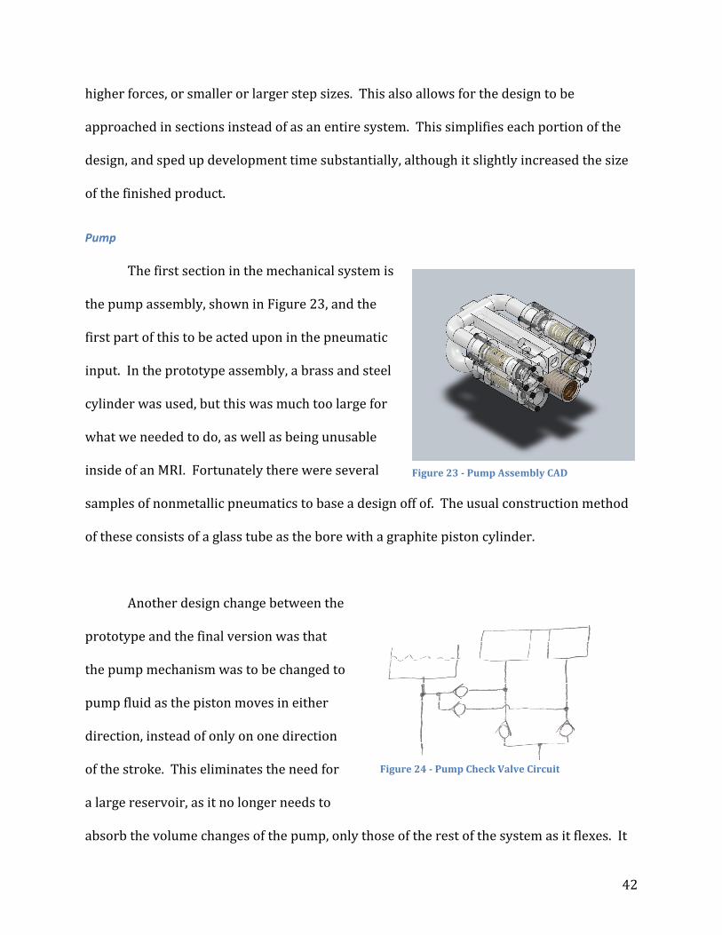
The first section in the mechanical system is
the pump assembly, shown in Figure 23, and the
first part of this to be acted upon in the pneumatic
input. In the prototype assembly, a brass and steel
cylinder was used, but this was much too large for
what we needed to do, as well as being unusable
inside of an MRI. Fortunately there were several
samples of nonmetallic pneumatics to base a design off of. The usual construction method
of these consists of a glass tube as the bore with a graphite piston cylinder.
Another design change between the
prototype and the final version was that
the pump mechanism was to be changed to
pump fluid as the piston moves in either
direction, instead of only on one direction
of the stroke. This eliminates the need for
a large reservoir, as it no longer needs to
absorb the volume changes of the pump, only those of the rest of the system as it flexes. It
Figure 23 Pump Assembly CAD
Figure 24 Pump Check Valve Circuit
43
also allows for a much faster pumping time, as the piston is both pushing fluid out and
drawing fluid in for the next cycle with the same motion. It is slightly more complex,
however, and requires a more sophisticated check valve circuit around it, shown in Figure
24.
To continue down this route of compatible pneumatics, all of the pistons in the
design would be made of graphite and use a glass bore. To reduce the machining required
on the graphite pieces, which is challenging in the WPI shops, all of the assemblies with
pneumatic inputs are designed to be single acting, so that the piston and the spring keep
whatever is between them in place without fasteners in the graphite. This will be
explained in more depth with each of these subassemblies.
With the pneumatic design principle determined, the pump design could continue.
The next decision to make was what volume should be displaced with each pump cycle.
However, to make this decision, we needed to know what the diameter of the driven piston
should be. A brief look at the available plastic tubing sizes and the approximate desired
size of the final assembly led to an assuming piston internal diameter of one inch, which
meant that for the 0.004 inch displacement, which gave a pump volume of just over 0.003
cubic inches.
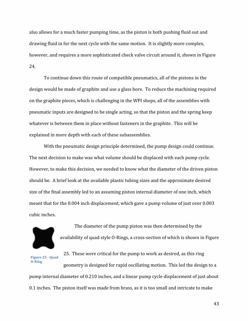
The diameter of the pump piston was then determined by the
availability of quad style O‐Rings, a cross‐section of which is shown in Figure
25. These were critical for the pump to work as desired, as this ring
geometry is designed for rapid oscillating motion. This led the design to a
pump internal diameter of 0.210 inches, and a linear pump cycle displacement of just about
0.1 inches. The piston itself was made from brass, as it is too small and intricate to make
Figure 25 Quad ORing

44
from plastic in the WPI shops. The tube that holds all of the pump components is made
from polycarbonate for strength. The return spring is a bronze compression spring with a
maximum load of 13.4 lb and a maximum displacement of 0.26 inches. This allows for
plenty of range to adjust the step size.
The pneumatic input to the pump was constructed by sliding a glass tube over the
main pump housing tube. This provides a piston diameter of 0.625 inches, which gives
enough force to completely compress the bronze spring for the maximum step size. The
graphite piston pushes against a garolite piston rod, used for its high rigidity despite a very
small diameter, which is attached to the
piston. The piston is connected to the
spring via another garolite rod to a plastic
disc used to press against the spring. The
whole assembly, shown in Figure 26, is
held captive by the pressure from the
spring on one end and the air pressure on
the other. This eliminates extra machining
on the graphite, which is challenging, and
keeps the piston piece itself relatively
simple.
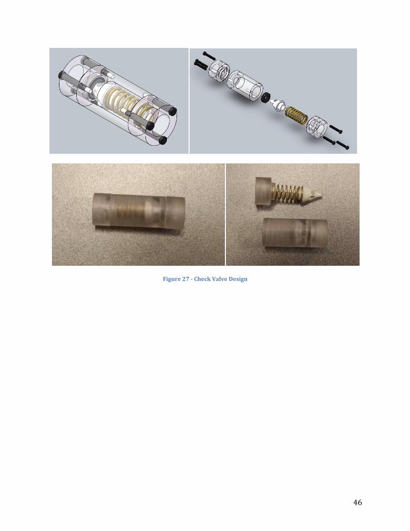
The pump circuit also requires check valves. These are used to turn the oscillations
of the piston into well defined forward steps. Each end of the pump cylinder has a check
valve between the reservoir and the pump, and another between the pump and the valves.
Figure 26 Pump Tube Assembly

45
While the flow recombines after the check valves, all of these are needed to make sure that
the pump does not recirculate any fluid while only forcing fluid forward through the
system.
Hydraulic check valves are generally made from steel, and even in plastic
construction check valves, the spring is still made from a ferrous material. This, along with
the difficulty in finding small check valves with low fluid resistances, meant that they
would need to be custom made. Check valves also come in two varieties: ball and dart. In a
ball check valve, a sphere is kept pressed against a seal ring by a spring. When pressure is
applied in the wrong direction, all it does is push the ball harder into the seal. However,
when fluid pressure is applied in the other direction, it pushes against the spring, and
opens the valve, allowing fluid to flow through. In a dart check valve, the ball is replaced
with a cone. This geometry allows for the valve to operate at much higher frequencies,
which definitely desirable in this application.
For the project to continue, custom MRI‐compatible dart style check valves needed
to be designed and constructed, the design and actualization of which are shown in Figure
27. The dart itself was made from PTFE for low friction against the polycarbonate casing.
The spring was a brass compression spring from McMaster‐Carr with a maximum load of
about 4 pounds, and was preloaded slightly to ensure that small pressure oscillations
would not open a valve in error. The seal ring is another quad O‐Ring to allow the rubber
to flex to accept any irregularities in the dart. Four of these, along with the pump tube
itself, are arranged together to create the full pump circuit.
46
Figure 27 Check Valve Design
47
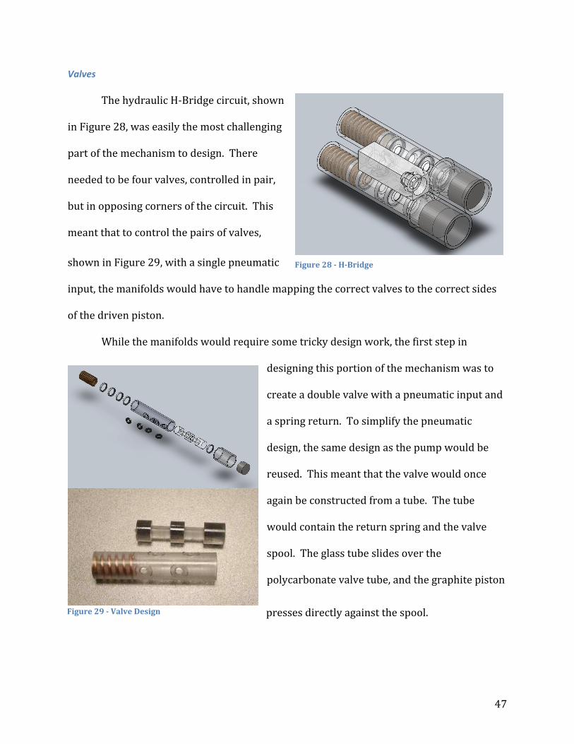
Valves
The hydraulic H‐Bridge circuit, shown
in Figure 28, was easily the most challenging
part of the mechanism to design. There
needed to be four valves, controlled in pair,
but in opposing corners of the circuit. This
meant that to control the pairs of valves,
shown in Figure 29, with a single pneumatic
input, the manifolds would have to handle mapping the correct valves to the correct sides
of the driven piston.
While the manifolds would require some tricky design work, the first step in
designing this portion of the mechanism was to
create a double valve with a pneumatic input and
a spring return. To simplify the pneumatic
design, the same design as the pump would be
reused. This meant that the valve would once
again be constructed from a tube. The tube
would contain the return spring and the valve
spool. The glass tube slides over the
polycarbonate valve tube, and the graphite piston
presses directly against the spool.
Figure 28 HBridge
Figure 29 Valve Design
48
The spool is the piece that determines what inputs are connected to which outputs.
The tube has inputs on one side, and outputs ninety degrees opposed, with an offset
between them. The offset allows for the spool to block the inputs when there is no air
pressure applied to the pneumatic. When pressure is applied, the spool presses against the
spring and shifts back to connect the inputs to the outputs, allowing flow through both
channels.
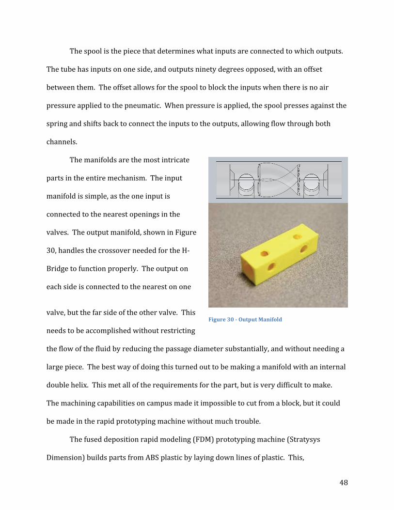
The manifolds are the most intricate
parts in the entire mechanism. The input
manifold is simple, as the one input is
connected to the nearest openings in the
valves. The output manifold, shown in Figure
30, handles the crossover needed for the H‐
Bridge to function properly. The output on
each side is connected to the nearest on one
valve, but the far side of the other valve. This
needs to be accomplished without restricting
the flow of the fluid by reducing the passage diameter substantially, and without needing a
large piece. The best way of doing this turned out to be making a manifold with an internal
double helix. This met all of the requirements for the part, but is very difficult to make.
The machining capabilities on campus made it impossible to cut from a block, but it could
be made in the rapid prototyping machine without much trouble.
The fused deposition rapid modeling (FDM) prototyping machine (Stratysys
Dimension) builds parts from ABS plastic by laying down lines of plastic. This,
Figure 30 Output Manifold

49
unfortunately, leaves a porous surface in the finished piece. While is not ordinarily an issue
for the parts the rapid prototype is used for, the hydraulic manifold could not have a
porous construction, as fluid could move in unpredictable way. By creating a small test
piece on the rapid prototyper, several different sealing methods were tested. Acetone was
one possibility; it would dissolve the outer layer of plastic, and when flushed with water,
would solidify into a solid skin. The acetone seeped too far into the plastic, and destroyed
the structure of the part. Instead, by injecting the test piece with the plumbing adhesive
used to build the prototype, and then removing the excess, the adhesive that seeped into
the pores hardened and created a skin that fluid could not leak through. This allowed the
printed part to be used as the output manifold of the valve system.
The valve block also contains the hydraulic reservoir for the mechanism. While the
double acting pistons prevents large fluctuation in volume, a small reservoir is still
important for ensuring that air can be removed from the system, and that any fluctuations
caused by flex in the tubing could be absorbed without effecting the system function. The
reservoir is also important for keeping the system supplied in the event of a small leak in
the system and for trapping any air that may have entered the system. The reservoir is
located at the equivalent of electrical ground; between the output of the H‐Bridge and the
input to the pump system.
50
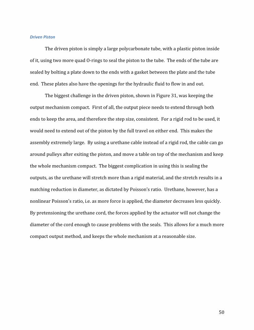
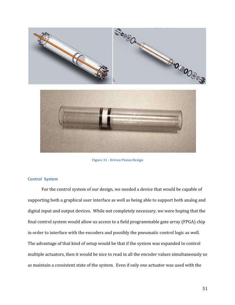
Driven Piston
The driven piston is simply a large polycarbonate tube, with a plastic piston inside
of it, using two more quad O‐rings to seal the piston to the tube. The ends of the tube are
sealed by bolting a plate down to the ends with a gasket between the plate and the tube
end. These plates also have the openings for the hydraulic fluid to flow in and out.
The biggest challenge in the driven piston, shown in Figure 31, was keeping the
output mechanism compact. First of all, the output piece needs to extend through both
ends to keep the area, and therefore the step size, consistent. For a rigid rod to be used, it
would need to extend out of the piston by the full travel on either end. This makes the
assembly extremely large. By using a urethane cable instead of a rigid rod, the cable can go
around pulleys after exiting the piston, and move a table on top of the mechanism and keep
the whole mechanism compact. The biggest complication in using this is sealing the
outputs, as the urethane will stretch more than a rigid material, and the stretch results in a
matching reduction in diameter, as dictated by Poisson’s ratio. Urethane, however, has a
nonlinear Poisson’s ratio, i.e. as more force is applied, the diameter decreases less quickly.
By pretensioning the urethane cord, the forces applied by the actuator will not change the
diameter of the cord enough to cause problems with the seals. This allows for a much more
compact output method, and keeps the whole mechanism at a reasonable size.
51
Figure 31 Driven Piston Design
Control System
For the control system of our design, we needed a device that would be capable of
supporting both a graphical user interface as well as being able to support both analog and
digital input and output devices. While not completely necessary, we were hoping that the
final control system would allow us access to a field programmable gate array (FPGA) chip
in order to interface with the encoders and possibly the pneumatic control logic as well.
The advantage of that kind of setup would be that if the system was expanded to control
multiple actuators, then it would be nice to read in all the encoder values simultaneously so
as maintain a consistent state of the system. Even if only one actuator was used with the

52
control system, there was still the need to read in a 12‐bit binary value, which would be
most effectively done in parallel. The ability to have parallel operations occurring on the
system allows for more consistent operation and should increase the safety and reliability
of the system. There is also the advantage that processing through the FPGA, especially just
combinational logic, can run exceptionally fast and not be potentially bogged down by
other parts of the code vying for control of the CPU. In order to perform the requested
functions, a small PC‐104 computer system with an FPGA interface board was originally
considered as that kind of setup had already been used in the lab for project work. Another
option we had was using a CompactRio (cRIO) device from National Instruments (NI) as the
team already had some experience with the system through its use in current FIRST
robotics competitions. The cRIO also had all of the components that we required for our
control system with the added benefit of having a chassis with interchangeable modules, so
that we could configure it with exactly the inputs and outputs that we would need. We
ended up working with NI to use one of their cRIO systems, as they are trying to get the
device used in various kinds of projects to show its modularity and encourage its
consideration during the design process. National Instruments ultimately donated a cRIO‐
9074 integrated chassis and controller system for our project, as well as 3 x NI 9403 TTL
Digital I/O Modules, 1 x NI 9477 Sinking Digital Output Module, 2 x NI 9201 Analog Input
Module, and 1 x NI 9263 Analog Output Module. This provided 96 DIO channels with the
9403 modules, allowing for six 12‐bit gray code encoders and 32 sinking DO channels to
operate the pneumatic valves for the actuators. The 9201 module could be used for
pressure sensors or magnetic field sensors, as well as for the user interface, and the 9263s
could be used for variable pressure valves.

53
Due to the need for extreme modularity in the final product, the National
Instruments CompactRIO was an excellent fit for the control system. The I/O modules
made it simple to maximize the number of actuators per controller, and the FPGA
simplified reading the encoder and allows the system to be run more quickly and
accurately, both of which are vital for the usability and safety of the mechanism.
Fiber Optic Daughterboard
The rest of the control system is implemented through the use of secondary
daughterboard specifically for the fiber optics, the schematic of which is shown in Figure
32. The fiber daughterboard was constructed to act as an intermediary between the cRIO
and the fiber optic cable. This was done to allow for signal conditioning outside of the
scope of the cRIO analog input module. The inputs to the daughterboard were the 12 fiber
optic strands that will carry the encoder information from the actuator assembly that can
then be filtered through the microprocessor
and output over 12 parallel TTL‐level lines to
digital inputs on the cRIO. The use of the
digital lines on the cRIO allows for more
encoders to be effectively used and provides
a higher speed and more efficient interface
than using the analog input directly. The
filtering on the microprocessor was done
because of the ease and dynamic
reconfigurability of a digital signal processing Figure 32 Fiber Daughterboard

54
solution. This was accomplished by reading in analog voltage levels through analog‐to‐
digital converters (ADCs) hopefully on the microcontroller itself. These voltage levels were
derived from photodiodes, after conversion from a current output to a voltage and
appropriate amplification.
This signal processing was facilitated on the fiber daughterboard by the use of a
PIC18F4553 microcontroller from Microchip Technology Inc. This particular
microcontroller was chosen primarily for its 13 on‐chip 12‐bits analog‐to‐digital
converters (ADCs), in order to allow for the high level of precision that could then be
achieved when thresholding the light intensities from the fiber optics, and its ability to be
obtained in a PDIP form factor. In addition to these characteristics, this microcontroller
also features a relatively high clock rate as well at RS‐232 serial and USB support. While
the USB support is not used for the current iteration of the daughterboard's design, that
functionality might be a perk in the future. A dcPIC30F4013 would also work just as well
for this application, but lacks USB support, and was ultimately not used based on the
availability of multiple PIC18F4553 microcontrollers in case something went wrong.
Since the microcontroller can be dynamically reconfigured over a serial connection
so that the thresholding levels can be set after the control system is initialized. In order to
effect serial communication between the microcontroller and the cRIO, a MAX232 TTL to
RS‐232 level converter to convert between the TTL voltage levels from the PIC chip and the
EIA‐232 levels used for RS‐232 serial communication. This is probably the most standard
solution for this particular interfacing problem and thus has a fair amount of
documentation and is why we chose it.
55
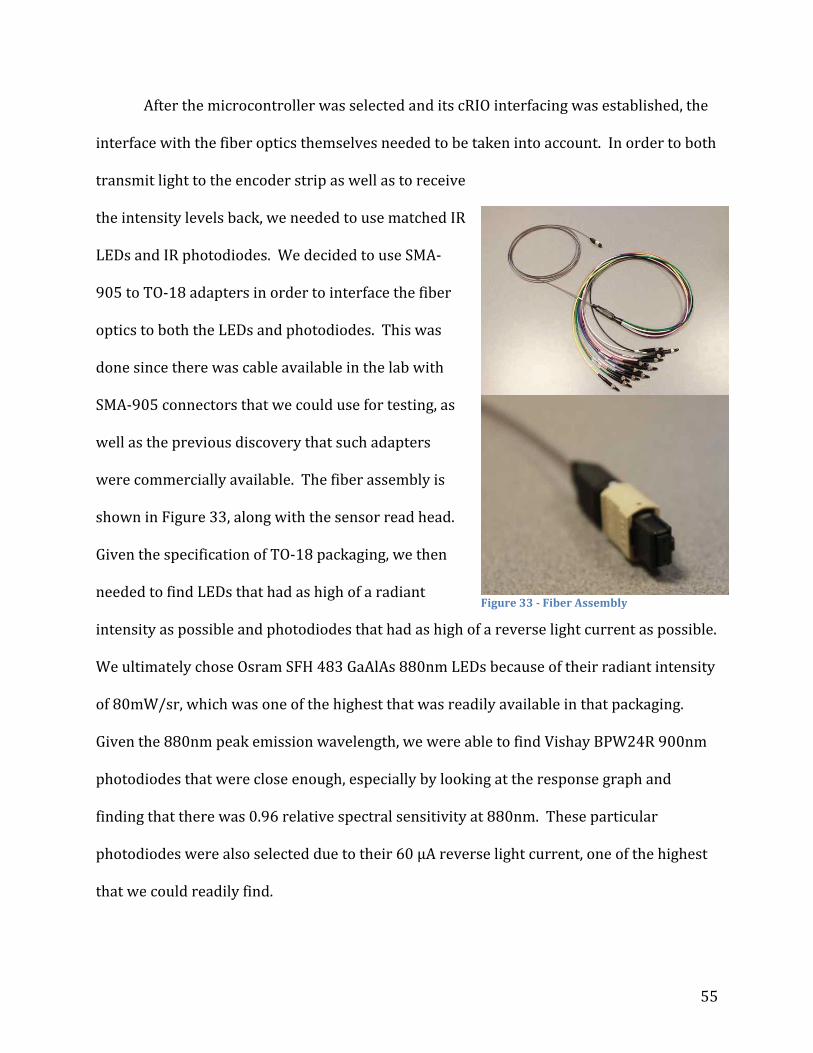
After the microcontroller was selected and its cRIO interfacing was established, the
interface with the fiber optics themselves needed to be taken into account. In order to both
transmit light to the encoder strip as well as to receive
the intensity levels back, we needed to use matched IR
LEDs and IR photodiodes. We decided to use SMA‐
905 to TO‐18 adapters in order to interface the fiber
optics to both the LEDs and photodiodes. This was
done since there was cable available in the lab with
SMA‐905 connectors that we could use for testing, as
well as the previous discovery that such adapters
were commercially available. The fiber assembly is
shown in Figure 33, along with the sensor read head.
Given the specification of TO‐18 packaging, we then
needed to find LEDs that had as high of a radiant
intensity as possible and photodiodes that had as high of a reverse light current as possible.
We ultimately chose Osram SFH 483 GaAlAs 880nm LEDs because of their radiant intensity
of 80mW/sr, which was one of the highest that was readily available in that packaging.
Given the 880nm peak emission wavelength, we were able to find Vishay BPW24R 900nm
photodiodes that were close enough, especially by looking at the response graph and
finding that there was 0.96 relative spectral sensitivity at 880nm. These particular
photodiodes were also selected due to their 60 μA reverse light current, one of the highest
that we could readily find.
Figure 33 Fiber Assembly

56
Since the photodiodes that we were using have a reverse dark current of 2 nA up to
a reverse light current of 60 μA, we chose to feed this current output to an op‐amp in a
current to voltage configuration. Initially LM348 quad op‐amps were chosen for use as the
current to voltage converters, but it was quickly realized that the input bias current was
too high to be effective when used with the photodiodes. For that reason, it was decided to
use LMC6484 CMOS op‐amps for that application. The difference being that the LM348 op‐
amps had an input bias current of 30 nA and the LMC6484 had an input bias current of 4
pA. The LM348 op‐amps were still useful for additional amplification stages as were
required due to the low level of light transmission through the fiber and thus a low level of
radiant light intensity reaching the photodiodes. In order to provide a negative rail for the
op‐amps, an ADM8828ARTZ voltage inverter is being used. This voltage inverter uses a
charge pump architecture to create the negative voltage and seems to be relatively
standard for the given application.
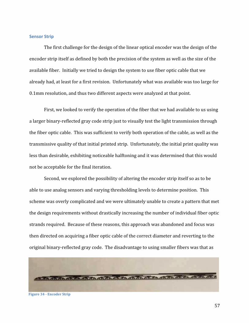
57
Sensor Strip
The first challenge for the design of the linear optical encoder was the design of the
encoder strip itself as defined by both the precision of the system as well as the size of the
available fiber. Initially we tried to design the system to use fiber optic cable that we
already had, at least for a first revision. Unfortunately what was available was too large for
0.1mm resolution, and thus two different aspects were analyzed at that point.
First, we looked to verify the operation of the fiber that we had available to us using
a larger binary‐reflected gray code strip just to visually test the light transmission through
the fiber optic cable. This was sufficient to verify both operation of the cable, as well as the
transmissive quality of that initial printed strip. Unfortunately, the initial print quality was
less than desirable, exhibiting noticeable halftoning and it was determined that this would
not be acceptable for the final iteration.
Second, we explored the possibility of altering the encoder strip itself so as to be
able to use analog sensors and varying thresholding levels to determine position. This
scheme was overly complicated and we were ultimately unable to create a pattern that met
the design requirements without drastically increasing the number of individual fiber optic
strands required. Because of these reasons, this approach was abandoned and focus was
then directed on acquiring a fiber optic cable of the correct diameter and reverting to the
original binary‐reflected gray code. The disadvantage to using smaller fibers was that as
Figure 34 Encoder Strip
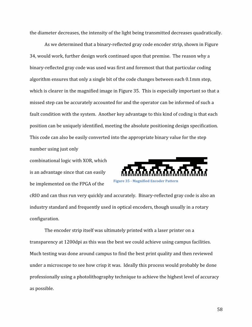
58
the diameter decreases, the intensity of the light being transmitted decreases quadratically.
As we determined that a binary‐reflected gray code encoder strip, shown in Figure
34, would work, further design work continued upon that premise. The reason why a
binary‐reflected gray code was used was first and foremost that that particular coding
algorithm ensures that only a single bit of the code changes between each 0.1mm step,
which is clearer in the magnified image in Figure 35. This is especially important so that a
missed step can be accurately accounted for and the operator can be informed of such a
fault condition with the system. Another key advantage to this kind of coding is that each
position can be uniquely identified, meeting the absolute positioning design specification.
This code can also be easily converted into the appropriate binary value for the step
number using just only
combinational logic with XOR, which
is an advantage since that can easily
be implemented on the FPGA of the
cRIO and can thus run very quickly and accurately. Binary‐reflected gray code is also an
industry standard and frequently used in optical encoders, though usually in a rotary
configuration.
The encoder strip itself was ultimately printed with a laser printer on a
transparency at 1200dpi as this was the best we could achieve using campus facilities.
Much testing was done around campus to find the best print quality and then reviewed
under a microscope to see how crisp it was. Ideally this process would probably be done
professionally using a photolithography technique to achieve the highest level of accuracy
as possible.
Figure 35 Magnified Encoder Pattern
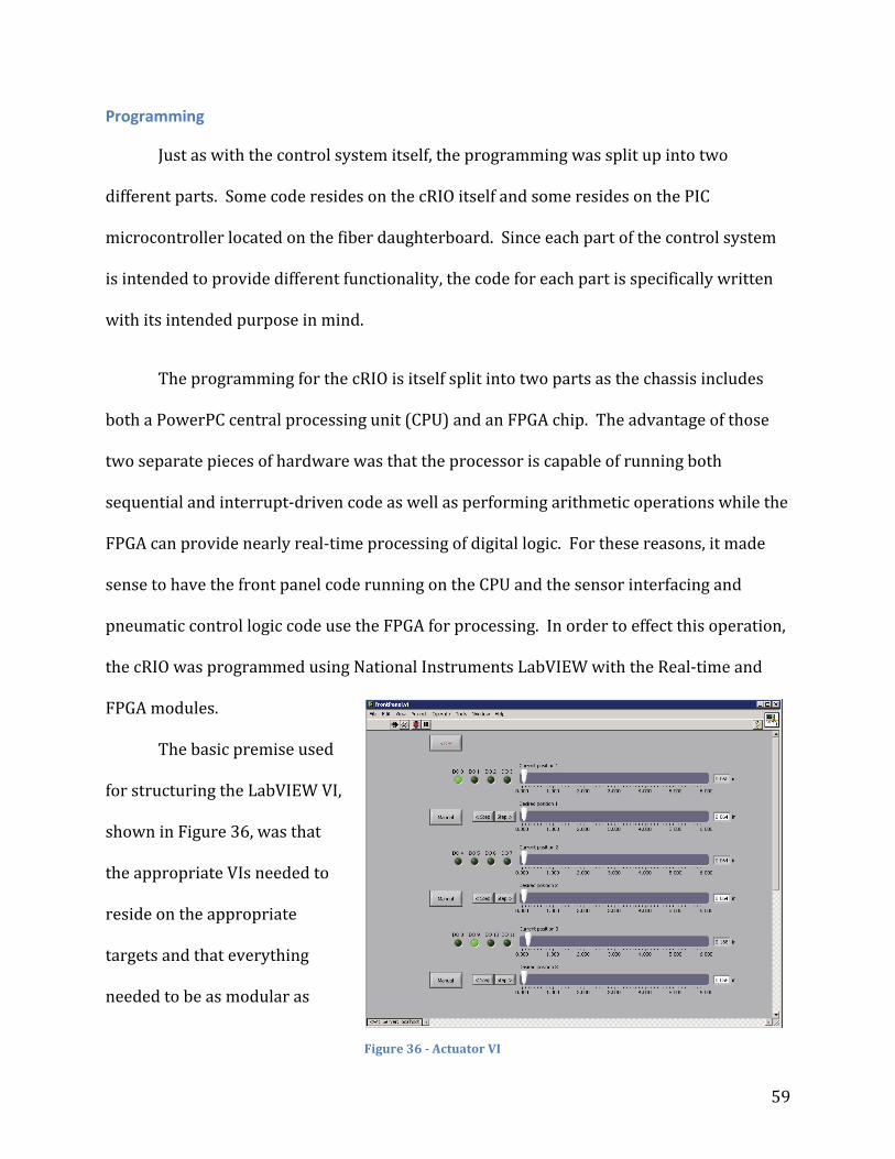
59
Programming
Just as with the control system itself, the programming was split up into two
different parts. Some code resides on the cRIO itself and some resides on the PIC
microcontroller located on the fiber daughterboard. Since each part of the control system
is intended to provide different functionality, the code for each part is specifically written
with its intended purpose in mind.
The programming for the cRIO is itself split into two parts as the chassis includes
both a PowerPC central processing unit (CPU) and an FPGA chip. The advantage of those
two separate pieces of hardware was that the processor is capable of running both
sequential and interrupt‐driven code as well as performing arithmetic operations while the
FPGA can provide nearly real‐time processing of digital logic. For these reasons, it made
sense to have the front panel code running on the CPU and the sensor interfacing and
pneumatic control logic code use the FPGA for processing. In order to effect this operation,
the cRIO was programmed using National Instruments LabVIEW with the Real‐time and
FPGA modules.
The basic premise used
for structuring the LabVIEW VI,
shown in Figure 36, was that
the appropriate VIs needed to
reside on the appropriate
targets and that everything
needed to be as modular as
Figure 36 Actuator VI

60
possible. A sub‐VI was written for the FPGA to handle the conversion from gray code to a
binary position value and was easily effected using just XOR gates in combinational logic. A
sub‐VI was also written that takes input about the current position of the system and the
desired position of the system and calculates the output values for the valve control to set
the appropriate direction on the H‐bridge as well as to determine whether the pneumatic
pump should be pumping or not. The front panel was ultimately constructed to be run on
the CPU of the cRIO and interfaces with the appropriate sub‐VIs to control the system. The
reason to use sub‐VIs was that they work similarly to subroutines in other programming
languages and allowed the control system to be expanded to control up to 6 actuators
under the current state of the system.
For the PIC microcontroller, there were only really two options for how to program
it, C and assembly. Ultimately most of the code is written in C with a few sections written in
assembly. C was used since it is much easier to code with and could be used to implement
all the functionality that was asked of it. The small bits of assembly code were used mostly
for low‐level operations like manipulating on‐chip memory. All of the code for the PIC
microcontroller was compiled with the PIC18 C and ASM compilers and is relatively simple.
The main function just sits in an infinite loop like most embedded systems stepping
through the ADC channels and reading in each of their values. These values are then
thresholded to the configured levels and outputted to a set of flip‐flops in order to latch the
current step value to be read by the cRIO.
61
Validation
Encoder
At the end of this project, the concept of the linear absolute optical encoder has been
proven. There has been no good way to accurately position the read head at this point, as
the mechanical assembly has not progressed to the level where this sort of alignment
accuracy can be achieved. However, the initial prototype fiber cable has been used to test a
large scale, low resolution encoder strip, and the concept has been shown to work.
The fiber daughterboard has been prototyped and tested outside of the fiber optic
sensor. By directly illuminating the photodiodes, use of the full range on the PIC ADC is
observable. Background lighting provides a readable signal, and covering the photodiodes
brings the reading very close to zero. This means that the photodiodes, the current to
voltage conversion circuit, and the PIC ADC are all working. The thresholding has been
programmed, but is not currently implemented. This is because the current fiber setup
does not provide enough light to give a reliable reading on the PIC ADC. By adding
additional amplification to the daughterboard circuit, this problem can be resolved, and all
that still needs to be set in the PIC are the thresholding cutoff values. The code is ready for
these to be configurable over a serial connection, however the hardware for this has not yet
been implemented.
Mechanical Design
The mechanical portion of the system is still largely in the manufacturing stage. The
subassemblies (e.g. pump tube, check valves, valve tubes, etc.) are completed, however the
housings for the system that keep everything together have not yet been finished. These
are large rapid prototyped components, and the lengthy lead time and tricky design of

62
these components has delayed their completion. The components have been tested in
isolation from the rest of the system, and function as they were intended. The system is
able to function without housings, but this plan has not been implemented yet.
The design itself should fulfill all of the design requirements, the travel is exactly the
six inch requirement, and the desired step size of 0.1mm is well within the tunable step size
of up to 0.25 mm. The valve system locks at a pressure loss and prevents any uncontrolled
motion. The hydraulic H‐bridge gives the mechanism all of the desired modes with only
two pneumatic inputs, and the whole package fits within a 1.5 by 5 by 9 inch box. The only
metal pieces in the entire mechanism are the brass and bronze springs, and the brass pump
piston, and all electronics have been removed from the actuator assembly.
Programming
The LabVIEW code has been finished, but not fully tested, once again because of the
mechanical assembly status. The gray code encoder decoder has been proven to work, and
can handle the resolution and time constraints imposed on it. The control loop for the
system also works, and determines the correct H‐bridge configuration and pump cycle
based off of the desired location and the actual location of the driven piston. The GUI is set
up to handle up to six actuators, but can easily be scaled back for any multi‐actuator
application that this mechanism was designed for.

63
System Integration
The system is, at the moment, still not fully integrated. The systems have all been
tested separately, and the software and mechanical portions have been tested together on
the prototype, however the current status of the mechanical assembly has prevented full
system integration and testing. There are no foreseeable issues with this, as all
components have been tested with simulated inputs from the other portions of the
actuator.

64
Discussion This project successfully developed a pneumatically‐controlled, MRI‐compatible
linear stepping actuator with real‐time position feedback. The design fulfilled the
requirements for precision, travel length, and force output. The hydraulic H‐bridge circuit
is a novel approach to a complex control problem, and is capable of providing the four drive
modes from only two inputs. The modularity requirement has been used as basis for
nearly all of the construction choices. Each portion of the hydraulic system was designed
as a separate module so that they can be swapped out to provide different step sizes,
travels, and/or forces. The actuators have also been designed to have the upper portion of
the case move; this allows for the actuators to be stacked on top of each other to provide
multiple axes of motion.
The quantitative design goals for the project have all been met. The 6 inches of
travel requirement defined the current version of the driven piston as well as the length of
the sensor strip. These components are designed to be easily changed to allow for any
travel needed. The step size is adjustable, but 0.1 mm is in the middle of the current
adjustable range, and the force requirement has been far surpassed, with a maximum
output of 300 pound‐force. This assumes that the force of a fully compressed spring is
applied to the fluid; in general operation the actuator will provide a force more on the
order of 30 pounds, still far more than was required. The end‐to‐end travel time has yet to
be tested, unfortunately, as the assembly must be completed for this. The 15 second target
is quite feasible as the fluid passages are all extremely large for the fluid flow velocities in
question.

65
Future Works
The mechanical portion of the project still needs to have a couple of pieces still
finished. The input manifold still needs some minor machining, as does the pump manifold
and the driven piston end caps. All machining should be completed within a week of this
report being turned in. The larger mechanical problems remaining are to finalize and test
fit the housings and assemble the mechanism in a realistic fashion. Testing outside of the
housings should prove that the basic concept of this design iteration is successful; without
the actual housings, the system will not behave as it would in its final setup. The actuator
has also not been tested inside of an actual MRI machine. The system has been built to the
highest standards of MRI‐compliance, however, and this should not be a problem.
The electrical and control systems, while functional independently of each other,
need to be integrated together. A large step toward this integration would be the transition
of the fiber daughterboard to a printed circuit board (PCB) so that the components that do
not interface well with a breadboard can be incorporated into the system. The integration
would also allow for the serial configuration subsystem to be utilized. In addition to the
electrical and control systems being integrated together, the encoder strip needs to be
mounted to the mechanical portion of the design. This includes mounting of the fiber optic
read head as well as a fiber to transmit the backlight to the encoder strip, potentially with
some sort of light guide to spread out the backlight across all 12 fibers on the read head. To
interface the fiber with the electrical system, the SMA‐905 to TO‐18 adapters need to be
mounted and the IR LED needs to be pulsed to maximize its radiant intensity.
Once these tasks have been completed, the first actuator will be ready for testing. At
this stage, the accuracy of the assembly will need to be verified, and the pump will need to

66
be tuned to give the proper step size. There is also the chance that one or more of the
subassemblies will need to be modified. None of the components have been tested in a full
assembly, so there could still be some issues getting them to work in concert.
After accuracy testing and MRI‐compliance testing, the actuator needs to be
replicated to test their modularity and attempt to make a multi‐axis assembly. This will
allow for the control software to be integrated with the output of the MRI to allow the
system to be controlled by the surgeon based on the patient’s status. Once this is ready, the
system needs to be tested in its final, clinical setting. Once this capability has been
established, the actuator will be completed and tested, and is ready for widespread use in
MRI robotics.

67
Works Cited 1. Liang, Zhi‐Pei, and Paul C. Lauterbur. Principles of Magnetic Resonance
Imaging: a Signal Processing Perspective. Bellingham, Wash.: SPIE Optical Engineering, 2000. Print.
2. Kuperman, Vadim. Magnetic Resonance Imaging: Physical Principles and
Applications. San Diego: Academic, 2000. Print.
3. Lux, Matthew M., et al. "Ergonomic evaluation and guidelines for use of the daVinci Robot System." Journal of Endourology 24.3 (2010): 371+. Academic OneFile. Web. 28 Apr. 2010.
4. "The Basics of NMR." RIT CIS Center for Imaging Science. Web. 18 Nov. 2009. <http://www.cis.rit.edu/htbooks/nmr/inside.htm>.
6. Young, Stuart W., and Stuart W. Young. Magnetic Resonance Imaging: Basic Principles. New York: Raven, 1988. Print.
8. De, Wolf David A. Essentials of Electromagnetics for Engineering. Cambridge:
Cambridge UP, 2001. Print. 9. Gilbert, John, Greg Wheeler, Richard Lingreen, and Robert Johnson. "Skip Navigation
LinksHome April 2006 ‐ Volume 19 ‐ Issue 2 Open Stand‐Up MRI: A New Instrument for Positional Neuroimaging" Journal of Spinal Disorders & Techniques 19.2 (2006): 151‐54. Web. 2 Jan. 2010.
10. Tabelow, Karsten, et al. "High‐resolution fMRI: Overcoming the signal‐to‐noise
problem." Journal of Neuroscience Methods 178.2 (2009): 357+. Academic OneFile. Web. 27 Apr. 2010.
11. "Implantable linear motor is made of piezoceramics for MRI." Advanced Materials &
Processes 163.7 (2005): 55. Academic OneFile. Web. 27 Apr. 2010. 12. Hashizume, Makoto. "MRI‐guided laparoscopic and robotic surgery for
malignancies." International Journal of Clinical Oncology 12.2 (2007): 94+. AcademicOneFile. Web. 27 Apr. 2010.
13. Muntener, Michael, Alexandru Patriciu, Doru Petrisor, Dumitru Mazilu, Herman
Bagga, Louis Kavoussi, Kevin Cleary, and Dan Stoianovici. "Magnetic

68
Resonance Imaging Compatible Robotic System for Fully Automated Brachytherapy Seed Placement." Urology (2006): 1313‐317. 2006muntener urology.pdf. Elsevier. Web. 27 Apr. 2010. <http://urobotics.urology.jhu.edu/pub/2006‐muntener‐urology.pdf>.
14. Weston, Richard, and Junsheng Pu. "Motion control of pneumatic drives."
Microprocessors and Microsystems 12.7 (1988): 373+. Academic OneFile. Web. 28 Apr. 2010.
15. Fischer, Greg, Axel Krieger, Iulian Iordachita, Csaba Csoma, Louis Whitcomb, and Gabor
Fichtinger. "MRI Compatibility of Robot Actuation Techniques – A Comparative Study." MICCAI 2008. Web.
16. Y. Yu, T. Podder, Y. Zhang, W. S. Ng, V. Misic, J. Sherman, L. Fu, D. Fuller, E. Messing, D. Rubens, J. Strang, and R. Brasacchio, “Robot‐assisted prostate brachytherapy,” Medical Image Computing and Computer‐Assisted Intervention ‐ MICCAI 2006. 9th International Conference. Proceedings, Part I (Lecture Notes in Computer Science Vol. 4190), (Berlin, Germany), pp. 41–9, Springer‐Verlag, 2006.
17. K Chinzei et al. (2000), Surgical assist robot for the active navigation in the intraoperative MRI: Hardware design issues. Proc IEEE/RSJ Int Conf on Robotics and Intelligent Systems (IROS): 727‐32
18. Elhawary H, Zivanovic A, Rea M, Davies B, Besant C, McRobbie D, Lamperth M, “A Modular Approach to MRI Compatible Robotics: Interconnectable One DOF stages,” IEEE Engineering in Medicine and Biology Magazine, Special Issue on MR Compatible Robotics, accepted for publication.
19. "World's first nonmagnetic robot arm." Machine Design 80.8 (2008): 40+. Academic OneFile. Web. 29 Apr. 2010.
20. Melzer, A.; Gutmann, B.; Remmele, T.; Wolf, R.; Lukoscheck, A.; Bock, M.; Bardenheuer,
H.; Fischer, H.; , "INNOMOTION for Percutaneous Image‐Guided Interventions," Engineering in Medicine and Biology Magazine, IEEE , vol.27, no.3, pp.66‐73, May‐ June 2008
21. Zu‐yan, MEI “Mechanical Design and Manufacturing of Hydraulic Machinery,”
Aldershot, Hants, England: Avebury Technical, 1991. Print.
22. Miller, John E. “The Reciprocating Pump, “ Malabar, Florida: Kreiger Publishing Company, 1995. Print.
23. Pippenger, John J; Hicks, Tyler G. “Industrial Hydraulics,” New York: Mc‐Graw Hill Publishing, 1979. Print.

69
Appendices
CAD Models
All prepared renders are in this appendix, the full CAD models can be found in
Solidworks format on a CD attached to the report or on file with Prof. Fischer.
Check Valve
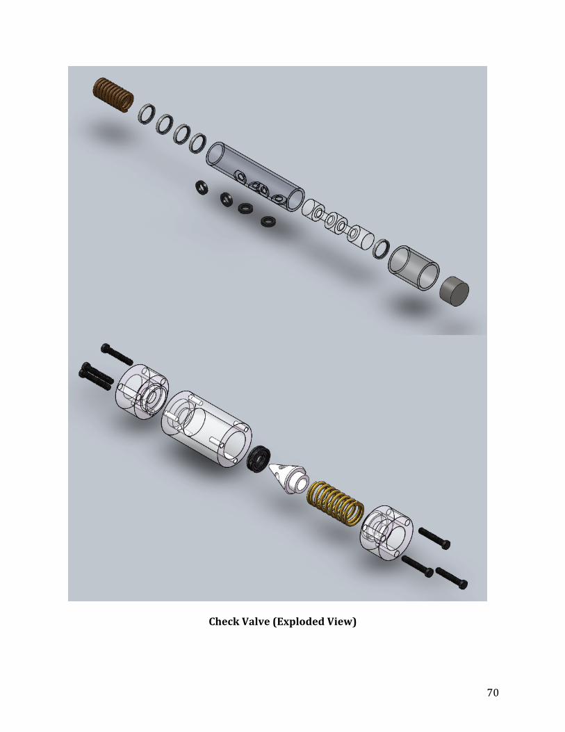
70
Check Valve (Exploded View)
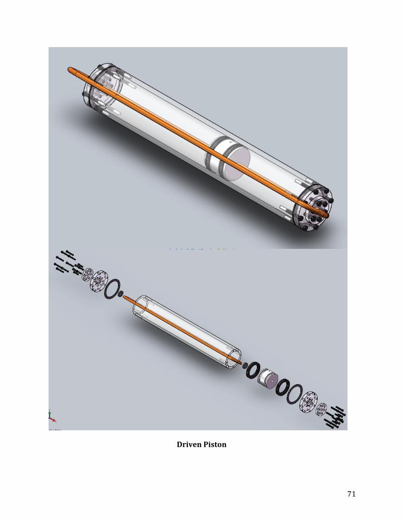
71
Driven Piston
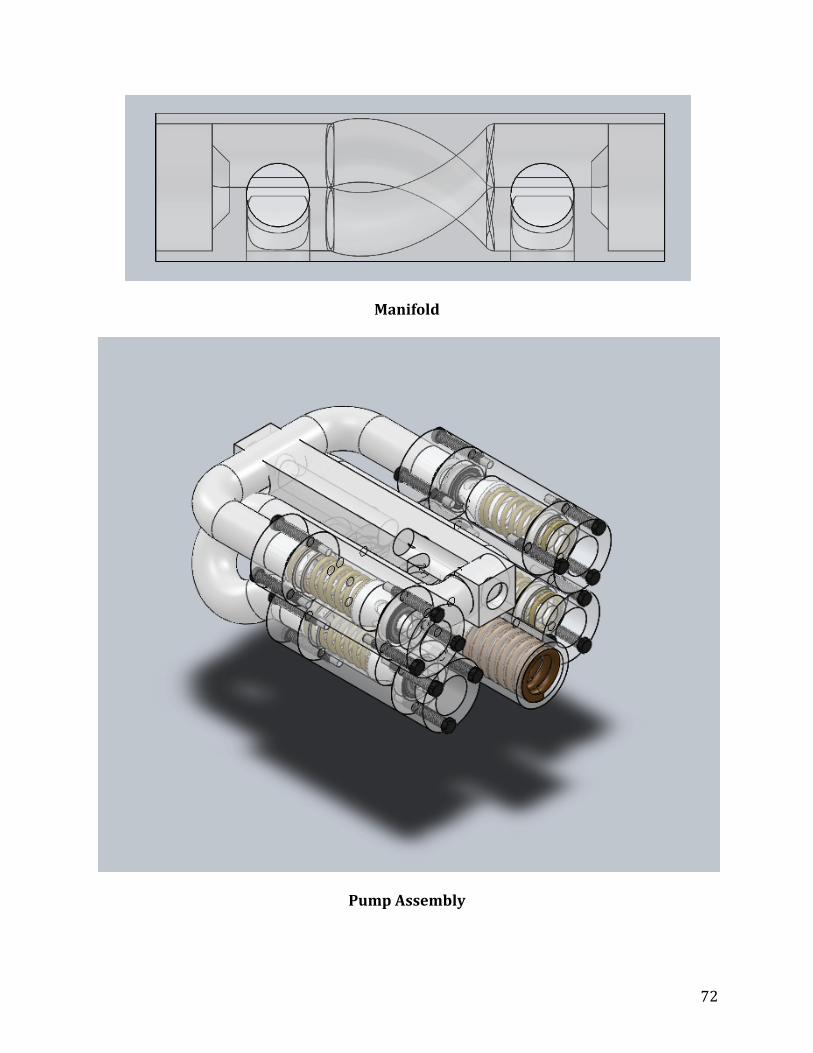
72
Manifold
Pump Assembly
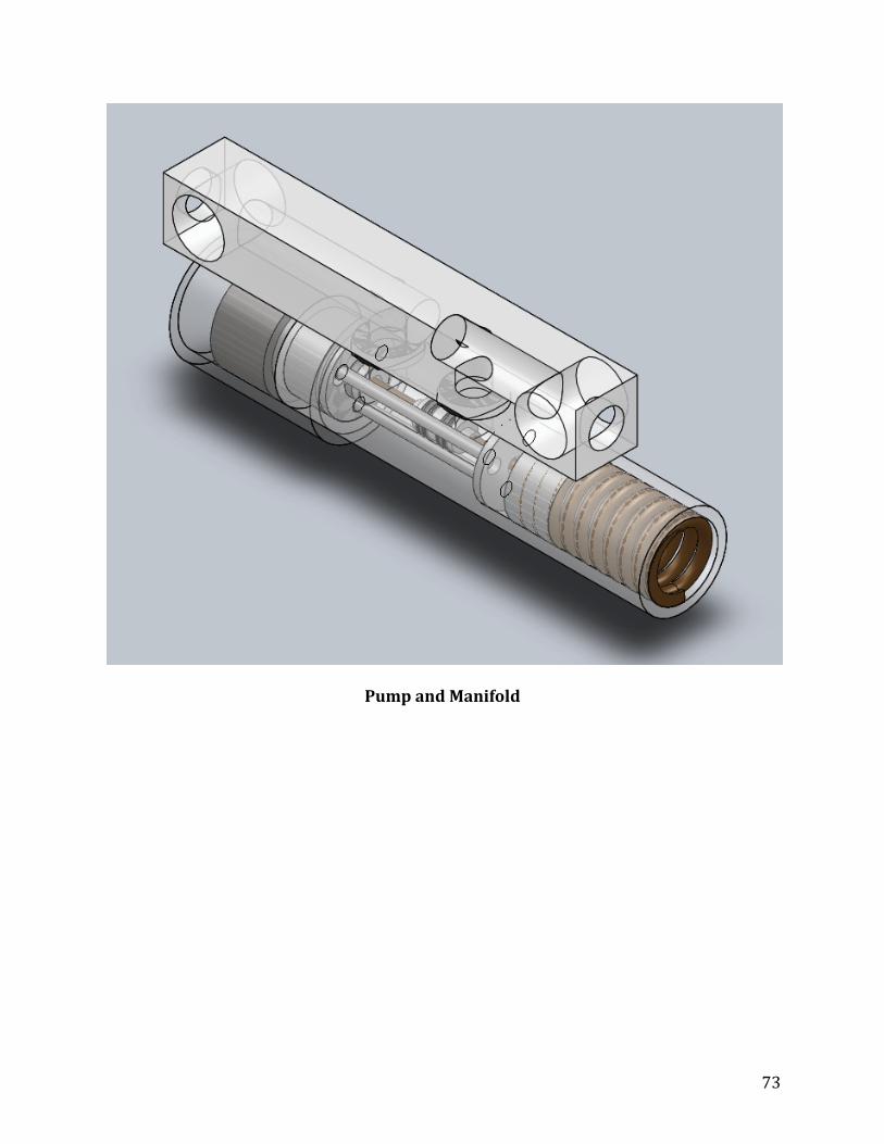
73
Pump and Manifold

74
Hydraulic Pump
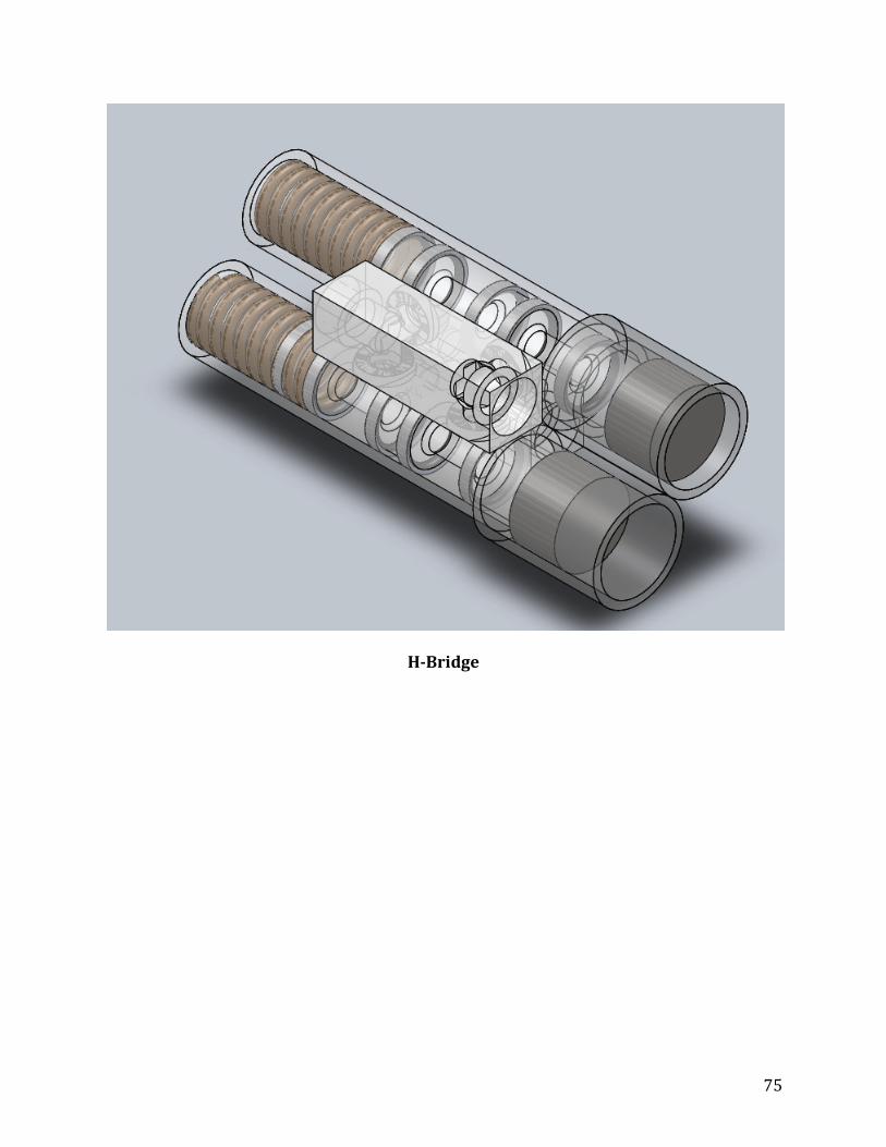
75
HBridge
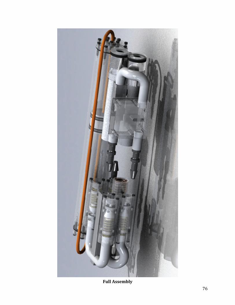
76
Full Assembly

77
Manufacturing Drawings
Full sized drawings are available on the documentation CD. The drawings in this
document have been reduced in size for brevity.
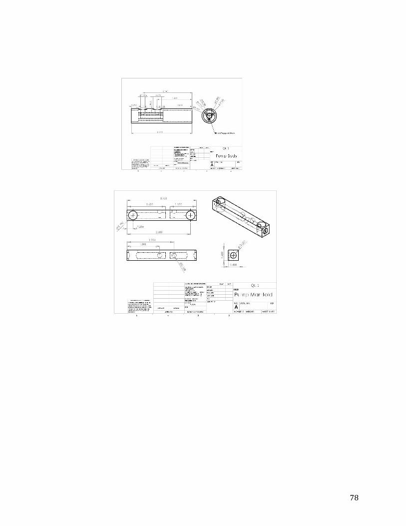
78

79
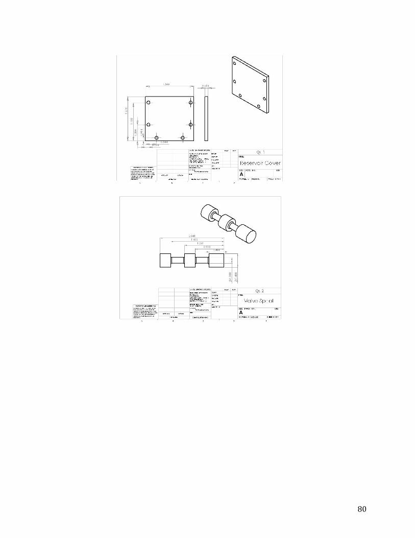
80

81
Component Information

82
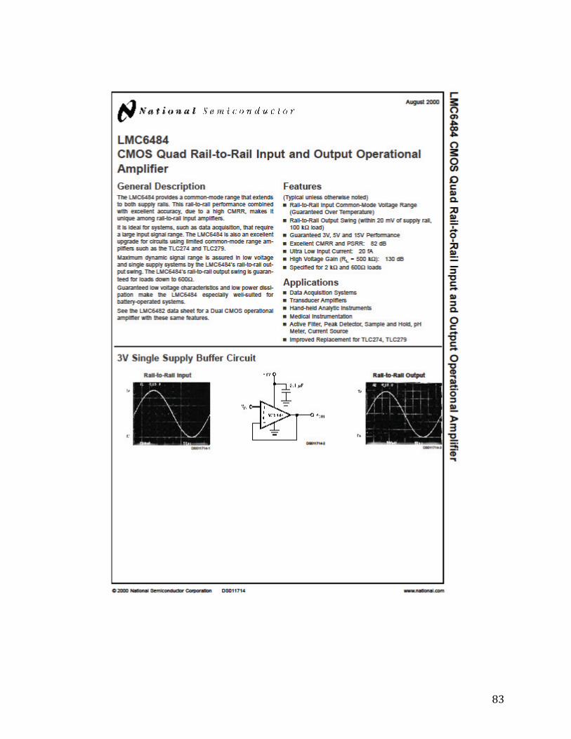
83

84

85
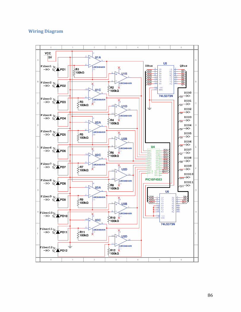
86
Wiring Diagram

87
LabVIEW
Prototype Stepper Code
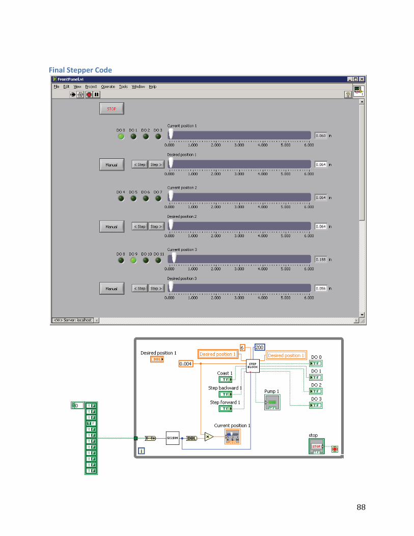
88
Final Stepper Code
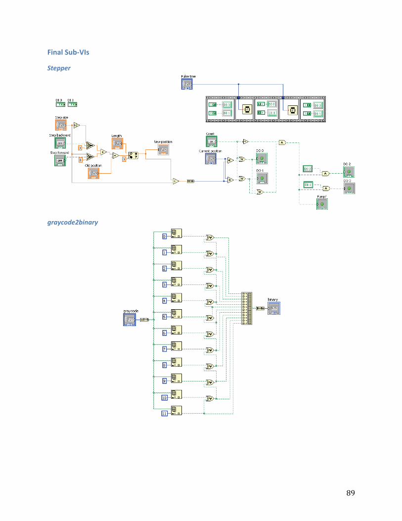
89
Final Sub‐VIs
Stepper
graycode2binary

90
PIC Code
Mrimqp.c /** * MRI MQP * * @author Andrew Smith ([email protected]) */ #include <p18f4553.h> #include "mrimqp.h" #include <stdlib.h> #include <delays.h> #pragma config FOSC = INTOSC_HS #pragma config WDT = OFF #pragma config PWRT = OFF #pragma config LVP = OFF void main(void) { //unsigned char a0, a1, a2, a3; unsigned short adcVal; init(); D0val = DON; D1val = DOFF; D2val = DON; D3val = DOFF; while(1) { //ADCON0 |= 0x00; Delay10KTCYx(25); ADCON0bits.GO = 1; while(ADCON0bits.NOT_DONE); adcVal = (unsigned short)(ADRESH) << 8 | ADRESL; D0val = (adcVal & 0x0001) ? DON : DOFF; D1val = (adcVal & 0x0002) ? DON : DOFF; D2val = (adcVal & 0x0004) ? DON : DOFF; D3val = (adcVal & 0x0008) ? DON : DOFF; D4val = (adcVal & 0x0010) ? DON : DOFF; D5val = (adcVal & 0x0020) ? DON : DOFF; D6val = (adcVal & 0x0040) ? DON : DOFF; D7val = (adcVal & 0x0080) ? DON : DOFF; D8val = (adcVal & 0x0100) ? DON : DOFF; D9val = (adcVal & 0x0200) ? DON : DOFF; D10val = (adcVal & 0x0400) ? DON : DOFF; D11val = (adcVal & 0x0800) ? DON : DOFF; } } /* Initialization */ void init(void) { /* Use internal oscillator */ OSCCONbits.SCS1 = 1; /* Turn off the Watch-Dog Timer */ WDTCONbits.SWDTEN = 0; PORTA = 0x00; ADCON0 = 0x01; ADCON1 = 0x0E; ADCON2 = 0xBF; CMCON = 0x07;

91
D0dir = OUTPUT; D1dir = OUTPUT; D2dir = OUTPUT; D3dir = OUTPUT; D4dir = OUTPUT; D5dir = OUTPUT; D6dir = OUTPUT; D7dir = OUTPUT; D8dir = OUTPUT; D9dir = OUTPUT; D10dir = OUTPUT; D11dir = OUTPUT; /*A0dir = INPUT; A1dir = INPUT; A2dir = INPUT; A3dir = INPUT;*/ } /* One microsecond delay */ void delay1us(void) { Nop(); return; }

92
Mrimqp.h #ifndef __MRIMQP_H #define __MRIMQP_H #define OUTPUT 0 #define INPUT 1 #define DOFF 0 #define DON 1 #define NUM_PINS 4 #define D0dir TRISAbits.TRISA3 #define D0val LATAbits.LATA3 #define D1dir TRISAbits.TRISA2 #define D1val LATAbits.LATA2 #define D2dir TRISAbits.TRISA1 #define D2val LATAbits.LATA1 #define D3dir TRISDbits.TRISD1 #define D3val LATDbits.LATD1 #define D4dir TRISEbits.TRISE1 #define D4val LATEbits.LATE1 #define D5dir TRISEbits.TRISE0 #define D5val LATEbits.LATE0 #define D6dir TRISDbits.TRISD0 #define D6val LATDbits.LATD0 #define D7dir TRISCbits.TRISC0 #define D7val LATCbits.LATC0 #define D8dir TRISCbits.TRISC1 #define D8val LATCbits.LATC1 #define D9dir TRISCbits.TRISC2 #define D9val LATCbits.LATC2 #define D10dir TRISAbits.TRISA4 #define D10val LATAbits.LATA4 #define D11dir TRISAbits.TRISA5 #define D11val LATAbits.LATA5 void init(void); void delay1us(void); #endif