pneumatic control - homestead · pneumatic controls require calibration •every pneumatic control...
TRANSCRIPT

Pneumatic Control

Terms
• Direct Acting (DA)
– The action of a controller that increases its branch line pressure as the controlled variable increases

Terms
• Reverse Acting (RA)
– The action of a controller that decreases its branch line pressure as the controlled variable increases

Terms
• Throttling range
– The change in the controlled condition necessary for the controller output to change over a 3-15 psig range.

Terms
• Authority Adjustment
– The adjustment on a receiver controller which determines the effect of the reset signal from a secondary transmitter as a percentage of the primary signal from the primary transmitter.

Devices PE
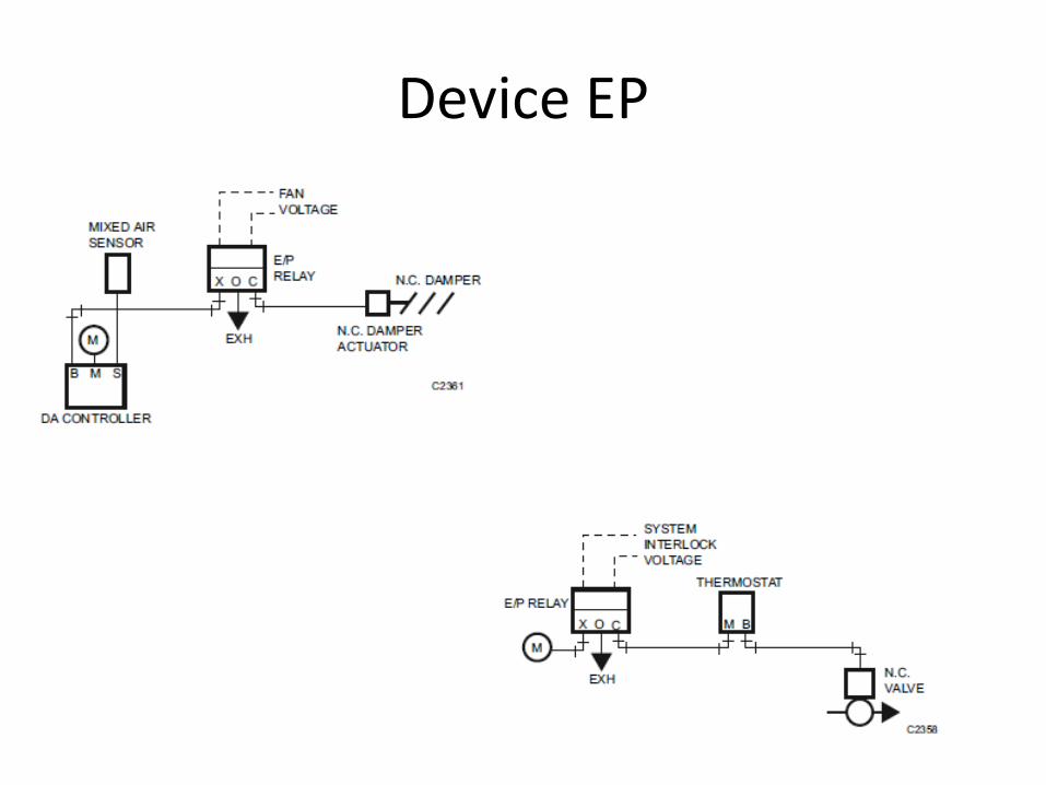
Device EP
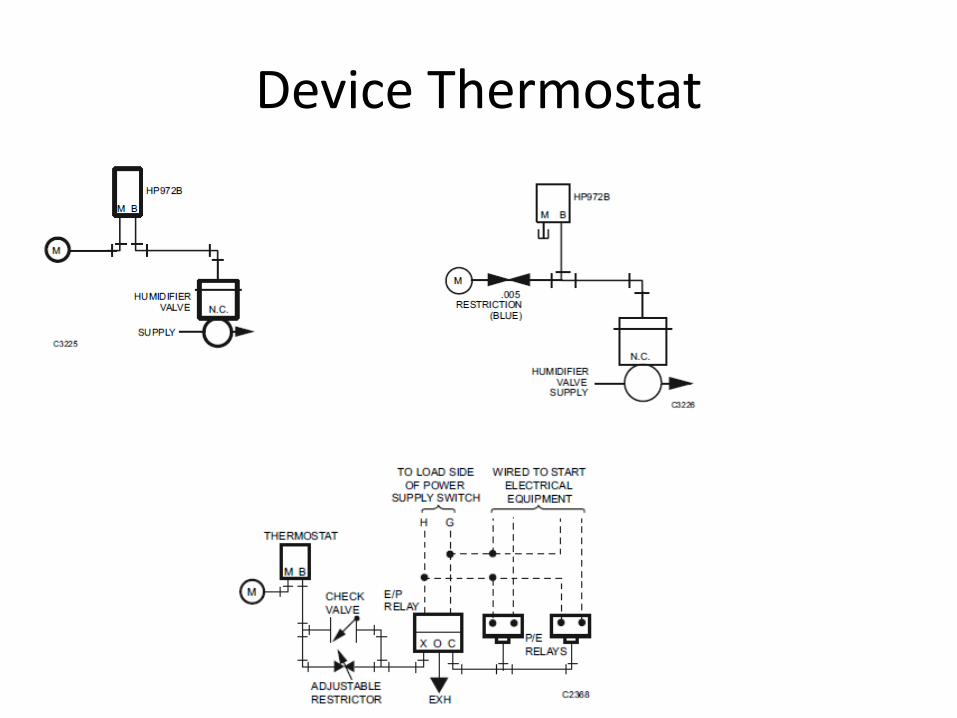
Device Thermostat

Device Reversing

Oil Free & Dry Control Air• Pneumatic control system’s worst enemy is air leaks. Air
systems are normally specified for a 33% run-time and some specifications have allowed up to a 50% run-time on the air compressor. To put this very simply, an air compressor runs a desired 20 minutes or up to a maximum of 30 minutes out of every hour. Excessive run-time can be caused by the air compressors inability to produce the air supply it was selected for or more likely caused by system air leaks.

Air Compressors


Two types of air compressors are most commonly used on pneumatic control systems. These air oil
lubricated and oil-less compressors. The excessive
run-time affects each compressor differently.
Air Compressors
Air Compressors
• The oil lubricated type compressor will overheat the cylinders and piston rings will wear, then oil will be allowed to pass past the rings into the air supply system. When the rings start to wear out the compressor will also need to run longer to produce the system air requirements and continues to compound the problem. These compressors are most commonly used because of the quieter operation.

Air Compressors
• The oil-less type compressor will overheat the cylinders and piston rings will wear out more quickly. Ring wear will not allow cylinders to compress or ring breakage causes broken piston rings to lodge against pistons and piston can become stuck. Stuck pistons break connecting rods or will make motor cycle on internal overloads. They do produce the best compressed air, but require the most maintenance and are much noisier than oil lubricated air compressors.
Air Compressors
• Pneumatic control air compressors use special internal oil control, which is designed to reduce oil carryover. Make sure you ask your supplier for this type of compressor

OIL FREE & DRY CONTROL AIR
• Refrigerated air dryers cool the air stream to a very low temperature, which will not support the high moisture of the compressed air. Moisture then condenses out of air stream and is then collected in a float/trap assembly. The water is drained out when trap level is exceeded. Oil filters are not always installed in a new system and are usually added if air compressor requires additional oil during operation.

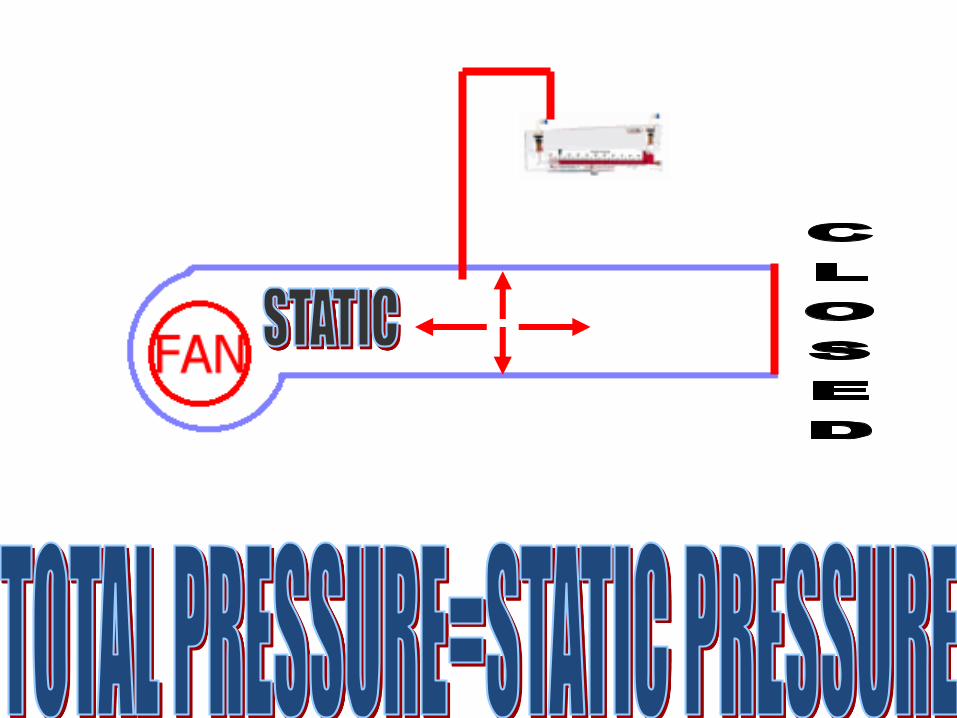
System Pressures
• Operating range 3-15 PSIG
• Compressor output max.30 PSIG
• 2 stage regulator first 16 second 20 to 25 PSIG.
• Some old systems run at 15 PSIG

Air-System
Air-Compressor
Relief Valve
Oil Filter
0-160 PSIG
0-30
PSIG30 PSIG
Relief
PRV
Auto Drain
Auto
Drain

Refrigerated Air Dryer
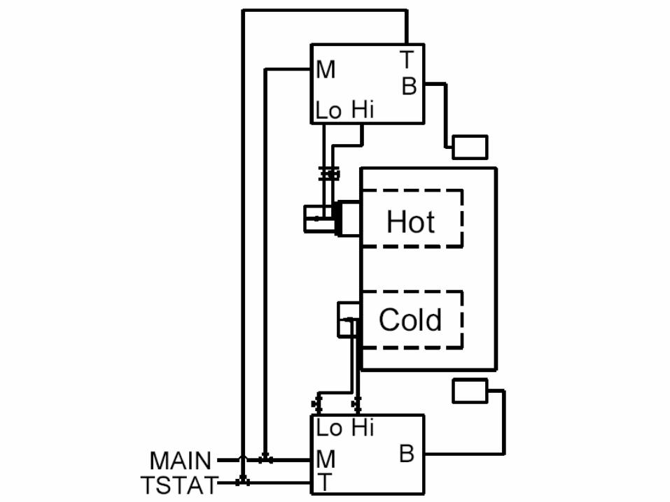
• The refrigerated air dryer cools the incoming compressed air first in an air-to-air heat exchanger where the outgoing cool dry air pre-cools the hot incoming air and condenses some moisture out.
• Then the incoming air enters an air-to-refrigerant heat exchanger where the air is cooled to 38º F by the liquid refrigerant. This process causes the moisture to condense into liquid water and it is drained away. The out going air then enters the air-to-air heat exchanger and is warmed up to keep the outside of pipes from sweating.
• The refrigeration compressor pumps hot hi-pressure gas refrigerant (Freon) into the condenser which transfers the heat from the refrigerant gas to the ambient air as the gas condenses into a liquid.
• The liquid refrigerant (Freon) is then metered to a cold low pressure where it enters the air-to-refrigerant heat exchanger and the heat from the hot compressed air is adsorbed into the cold refrigerant (Freon).
• The refrigeration compressor then sucks low pressure hot gas refrigerant (Freon) into the refrigeration compressor and the cycle starts over again.
Thermostats

Single Pipe

Two Pipe

Pneumatic Thermostat
• Modulates compressed air to control pneumatic components when a change in space conditions is sensed.
• The thermostat bleeds or BILDS air pressure to affect system pressure in the pneumatic piping.
• Can be 1 or 2 pipe models.

Thermostats Pneumatic
• Use one pipe thermostat when tubing run is less than 50 ft
• Fewer than four controllers will be controlled from a single stat.
• Slower response is desired from stat.
Thermostats Pneumatic
• Use two pipe stat when
• Tubing runs more than 50 ft.
• Four or more controllers from a single stat.
• High capacity air is required dure to restrictions in the air line.
Thermostats Pneumatic
• In general both one and two pipe states have a gain of 2.5 psi per degree Fahrenheit.

B M
Room Thermostat
M
15-25 psig
Control Valve
Temperature Controller Application
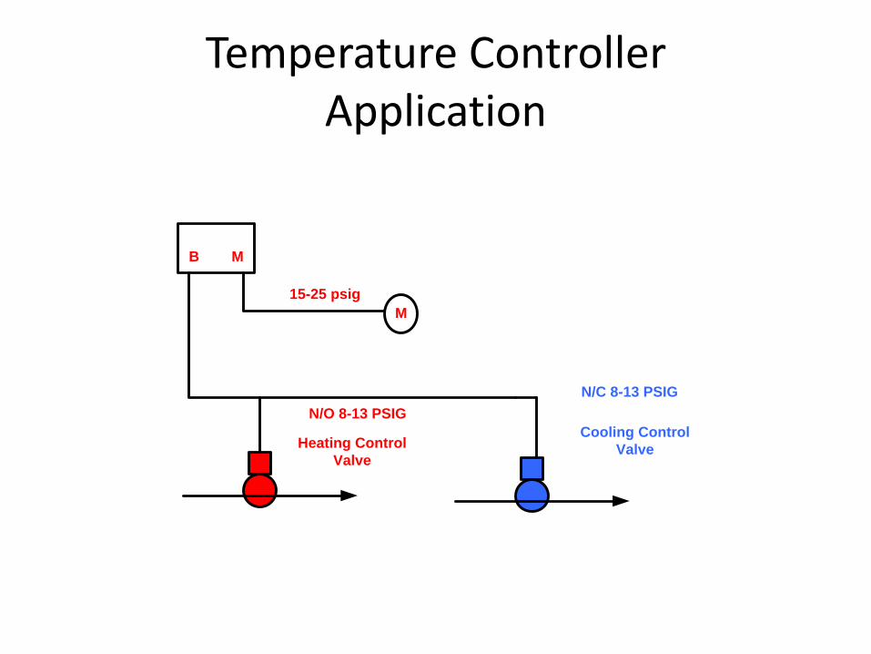
Temperature ControllerApplication
B M
M
15-25 psig
Cooling Control
Valve
N/C 8-13 PSIG
N/O 8-13 PSIG
Heating Control
Valve

B
20 psig
Control Valve
Single Pipe Thermostats

B M
M
15-25 psig
Control Valve
Coil
C
N/O
N/C
3 Way Valve
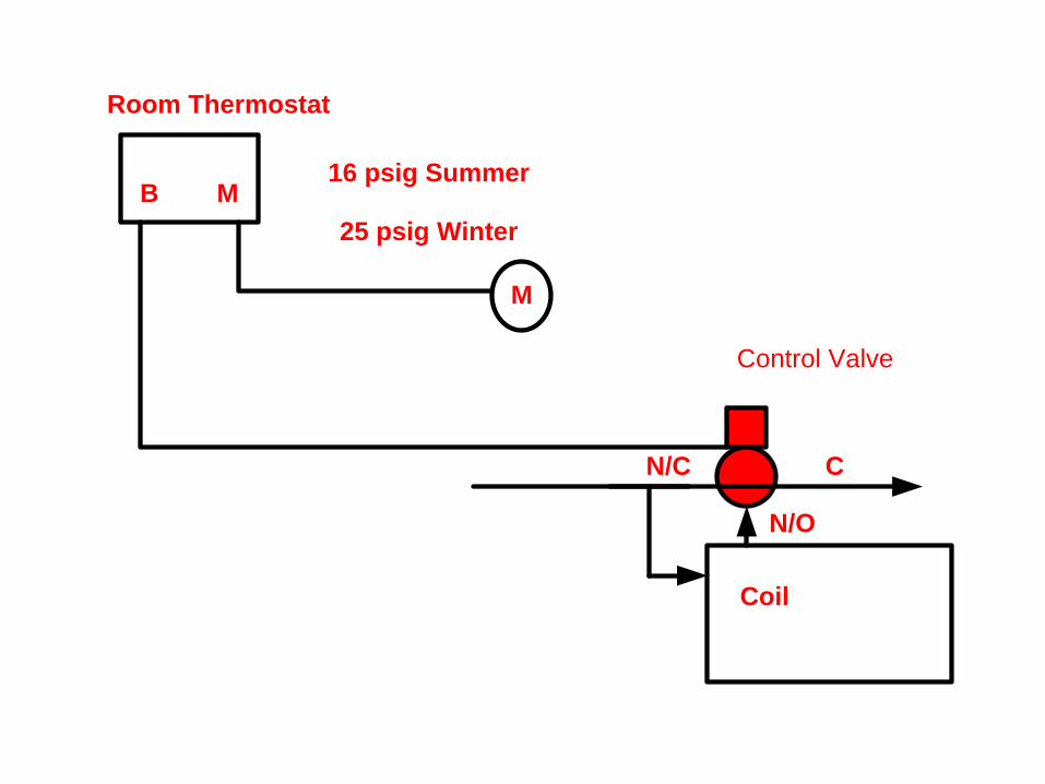
B M
Room Thermostat
M
25 psig Winter
Control Valve
Coil
C
N/O
N/C
16 psig Summer

B M
Room Thermostat
M
N
P.E.
Switch
n/o c n/c
To Electric Device

Master/SubmasterController
• A master controller is a pneumatic controller which transmits its output signal to another controller
• The second controller or submaster is similar to the standard type controller
• The significant difference is that the submaster set point will change as the signal from the master controller changes.
• This is normal used for reset

B M
Master
M
Control Valve
B M R
Submaster
Space
Thermostat

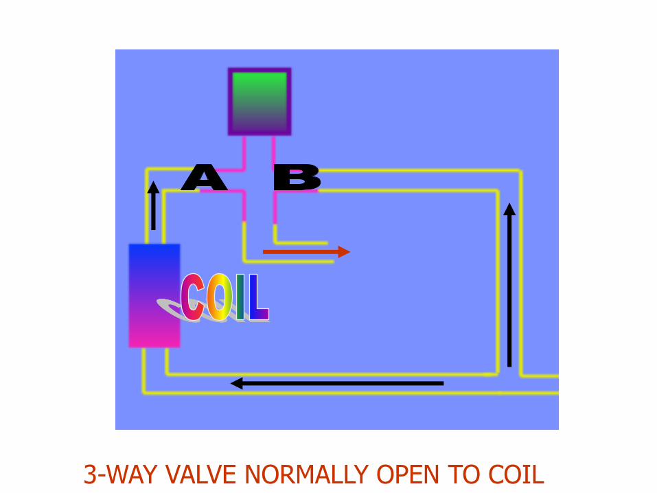
3-WAY VALVE NORMALLY OPEN TO COIL

3-WAY VALVE NORMALLY CLOSED TO COIL

2-WAY VALVE NORMALLY 0PEN TO COIL
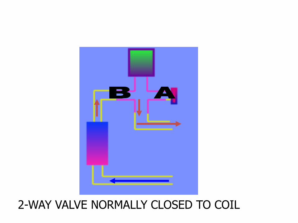
2-WAY VALVE NORMALLY CLOSED TO COIL
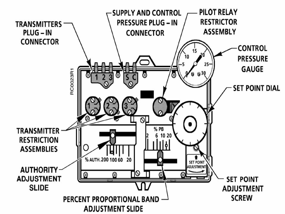
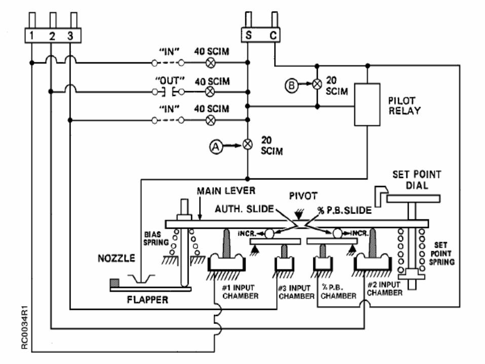
Receiver Controller

Receiver Controller Terms
Transmitters• Pneumatic temperature transmitters are
designed to measure air or fluid Temperature In pneumatic control systems
• The range is 3- 15 PSIG
Span
• The difference between a temperature controllers or transmitter lowest possible set point and the highest possible set point.
• Example 40 to 240 deg

Terms
• Throttling range
– The change in the controlled condition necessary for the controller output to change over a 3-15 psig range.
– TR = in % TR/Span
– Example 40- 140 Deg Transmitter
– You would like a 20 Throttling range
– % = 20/100 or 20%

Terms
• Authority Adjustment Or Ratio
– The adjustment on a receiver controller which determines the effect of the reset signal from a secondary transmitter as a percentage of the primary signal from the primary transmitter.

Terms
• Sensitivity or Gain
– The psig change in transmitter output signal per engineering unit. Degree, %, RH, ETC.
– Sensitivity =
12 PSIG ( output Span)
Transmitter Span

Temperature Transmitters sensitivity
Example = 3-15 PSI 12----------------- = ------- = .12 PSI/Degree 0-100
Range 100
50 degrees x .12 = 6.00 PSI + 3 PSI (Low Value) = 9 PSI or 50 Degree

?
• What you are trying to control to

Integral
• The integral calculation responds to the length of time the measured variable is not at setpoint. The longer the measured variable is not at setpoint the larger the output of the integral calculation.

Proportional
• This calculation responds to how far the measured variable is from the setpoint.
• The proportional calculation has a much stronger effect on the result of the PID calculation than either the integral or derivative calculation.
Drivative
• This calculation responds to the change in error.
• In other words it responds to how quickly the measured variable is approaching setpoint
• This calculation can be used to smooth an actuator motion or cause an actuator to react faster


Single Input Receiver Controller Application
MControl Valve
C
N/O
N/C
B SM
Discharge
Air
Temp.
transmitter
Supply
Return

Single Input Calibration
• Set for direct or reverse action using spring and pivot screws ETC.
• Calculate proportional Band.
Proportional band =
Throttling range
Sensor Span X100
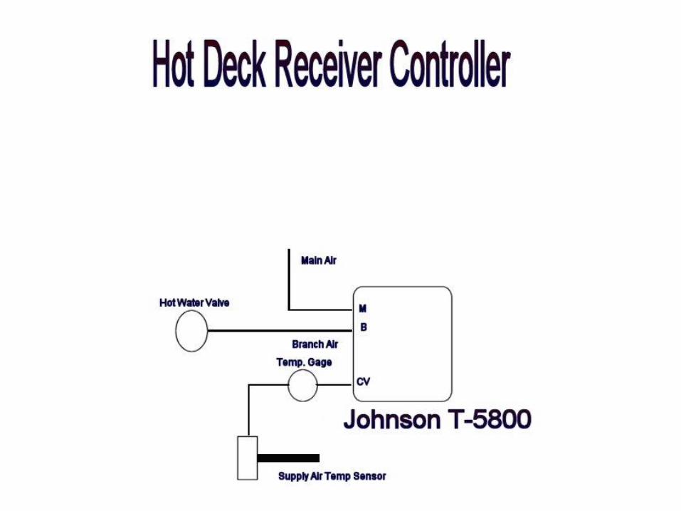
Receiver Controller
MControl Valve
C
N/O
N/C
B SM
Discharge
Air
Temp.
transmitter
Supply
Return
S
OSA
Temp.
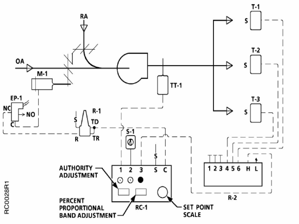
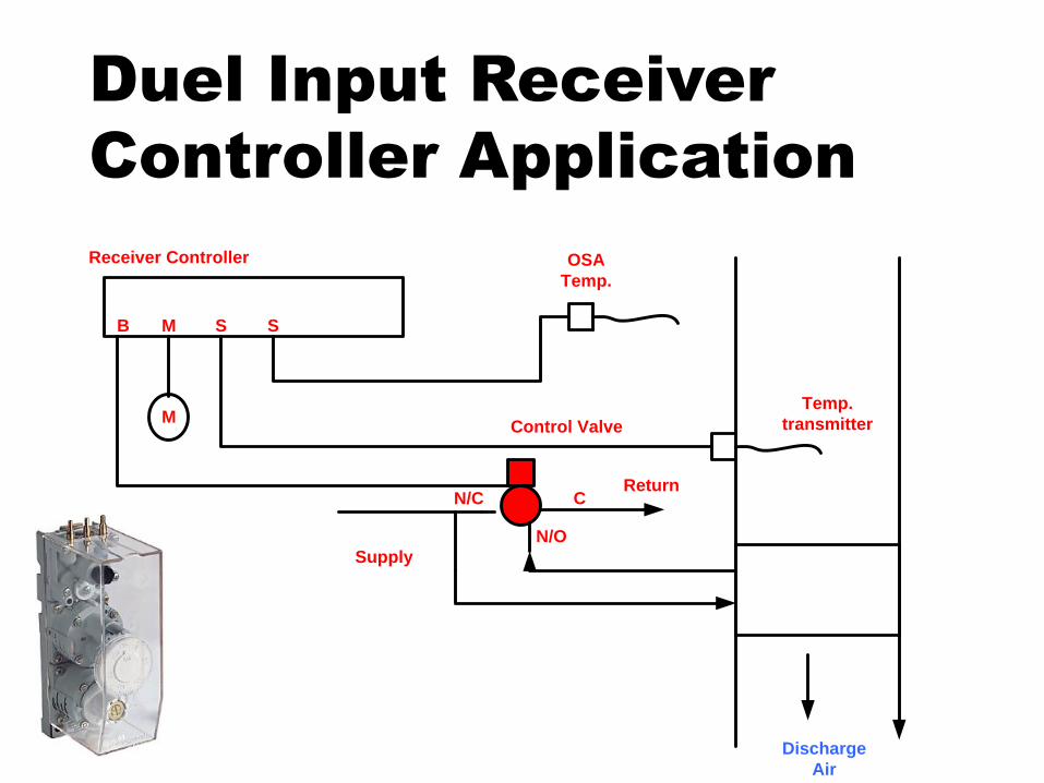
Duel Input Receiver
Controller Application

Duel input Calibration Example See IOM For your Receiver controler

Duel input Calabration

Duel input Calabration
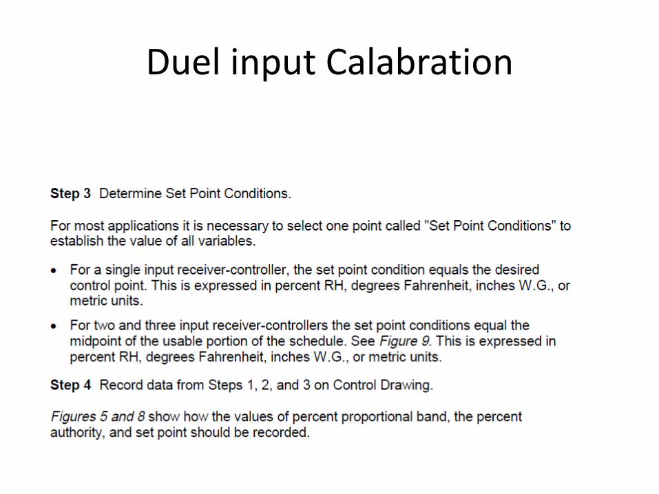
Duel input Calabration

Reset Schedule
T1 Supply T2 OSA
200 Deg. 0 Deg.
150 Deg. 32 Deg.
100 Deg. 65 Deg.


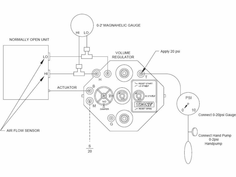
Pneumatic Controls Require Calibration
• Every pneumatic control needs annual calibration at a minimum. Devices such as heat/cool thermostats need calibration twice a year. All pneumatic devices are calibrated in a similar manner, but will require other devices to be checked prior to it being calibrated. This will be explained further below.

Thermostats
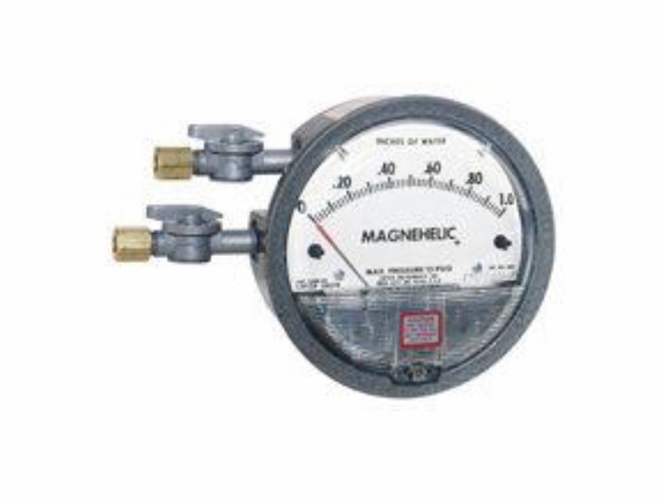
• A pneumatic gauge is installed in the thermostat calibration port (this will very by manufacturer). Some will use a gauge connected to an end similar to a petes plug pressure needle, some will use ends similar to hypodermic needles, and others just un-screw a plug, then pushed a flexible hose over this plug. A temperature reading is taken at the thermostat and thermostat set-point dial is set to the temperature we read earlier. If the thermostat is calibrated, then the gauge pressure reading should equal 8 PSI. Every manufacturer does have a different way of calibration if it is above or below the 8PSI and you can get a copy of this procedure from the manufacturer.

Temperature Transmitters
• Transmitters are used to transmit a temperature value in pressure units. They will transmit these values to other pneumatic devices (i.e. Receiver Controllers, Switching Relays, Etc.). Every transmitter has a range or scale (i.e. 0-100 Degrees, -40-120 degrees, etc.) that its pressure output is to correlate too. The transmitters will very its temperature over the scale or range vs. its 3-15 PSI output. Take a temperature reading at the transmitter-sensing element and for our example it was 50 degree. A pressure gauge with 1/10th of pound markings will help in getting accurate pressure readings or you can buy a receiver control calibration/simulation tool that already has these gauges.

Receiver Controllers
• This device is the most versatile of all pneumatic control devices. The transmitters sensing temperature, humidity, pressure or other values transmit a signal that is proportional to the medium being sensed. This signal is transmitted to a summing and amplifying point where it is converted to a control signal. This control signal leads to a controlled device and, in turn, corrects the controlled medium.

Receiver Controllers
• The control strategies that this device can perform are single input proportional, reset control, high & low limit control, differential temperature control, differential pressure control and many others.

Receiver Controllers
• The best method of checking calibration of this device is to use a receiver controller calibration/simulator. All inputs can be varied to test it against the correction made to the control signal output.

Controlled Devices

VAV Systems
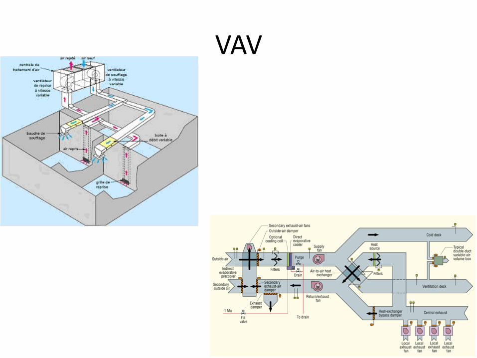
VAV

Small control valves
• You can hook-up a squeeze bulb to the diaphragm, pump it up to 15 PSI and check to see if it holds pressure. If it does not hold pressure, then replace the valve diaphragm.
Small control valves
• Another replacement part on this type of valve is the seat disc. These can be replaced if valve allows a temperature rise or drop past the valve when shut. Verify that the system operating pressure has not exceeded the valves close-off capabilities before condemning valve seat. If disc replacement does not resolve temperature rise or drop, then the seat has a problem. Most of these valves are built to be cost effective and very few have the ability to replace the valve seat. The seat is usually machined into the bronze valve body and the only resolution in this type of valve is to replace it.

Small control valves
• The last part that is replaceable in this type of valve is the packing around the valve stem. Not all manufacturers make a valve with replaceable packing discs and if valve leaks around the stem, it will need to be replaced. If valve does have replaceable packing, then remove valve operator, take out packing with a packing pick and inspect valve stem. If valve stem shows a lot of corrosion, then do not bother trying to re-pack the valve stem, since it will more than likely leak again. Some older valves did not use packing and used a flexible bellows assembly attached to the stem. These bellows can be replaced, but you might want to evaluate this repair vs. the valve replacement.

Large Control Valves
• You can hook-up a squeeze bulb to the diaphragm, pump it up to 15 PSI and check to see if it holds pressure. If it does not hold pressure, then replace the valve diaphragm.
Large Control Valves
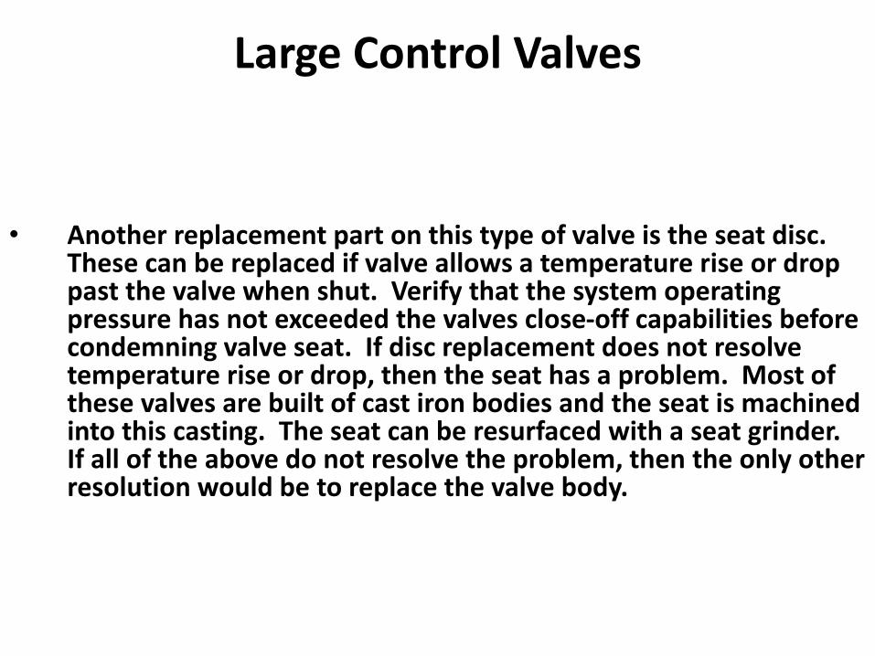
• Another replacement part on this type of valve is the seat disc. These can be replaced if valve allows a temperature rise or drop past the valve when shut. Verify that the system operating pressure has not exceeded the valves close-off capabilities before condemning valve seat. If disc replacement does not resolve temperature rise or drop, then the seat has a problem. Most of these valves are built of cast iron bodies and the seat is machined into this casting. The seat can be resurfaced with a seat grinder. If all of the above do not resolve the problem, then the only other resolution would be to replace the valve body.
Large Control Valves
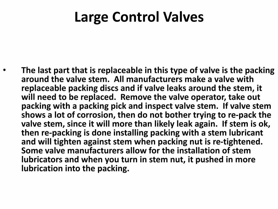
• The last part that is replaceable in this type of valve is the packing around the valve stem. All manufacturers make a valve with replaceable packing discs and if valve leaks around the stem, it will need to be replaced. Remove the valve operator, take out packing with a packing pick and inspect valve stem. If valve stem shows a lot of corrosion, then do not bother trying to re-pack the valve stem, since it will more than likely leak again. If stem is ok, then re-packing is done installing packing with a stem lubricant and will tighten against stem when packing nut is re-tightened. Some valve manufacturers allow for the installation of stem lubricators and when you turn in stem nut, it pushed in more lubrication into the packing.

Damper Operators
• You can hook-up a squeeze bulb to the diaphragm, pump it up to 15 PSI and check to see if it holds pressure. If it does not hold pressure, then replace the valve diaphragm.

Damper Operators
• The operation is normally sequenced with other devices. This depends on the spring ranges of each to properly open/close at the right pressure. If springs weaken, they will not sequence properly and you can install a pilot positioner, which will be set to open or close at proper pressure. Some system specifications require these on all sequenced devices and will not allow sequencing to be done only by the spring ranges.

Dampers
• These devices do not need much preventative maintenance, but external linkages can loosen, which will not allow dampers to fully shut. Damper should be stroked fully open and closed to verify that it they work properly. Large dampers are linked with jack shafting and these can also not open/close all damper sections uniformly. Adjustments may be necessary to verify that this operation occurs.

Dampers
Some damper manufacturers suggest that a Teflon lubricant be sprayed on moving parts to maintain smooth operation.

Pneumatic Controls Components
• Pneumatic Volume Regulator
• Reversing Relay
• Signal Limiter
• Booster Relay


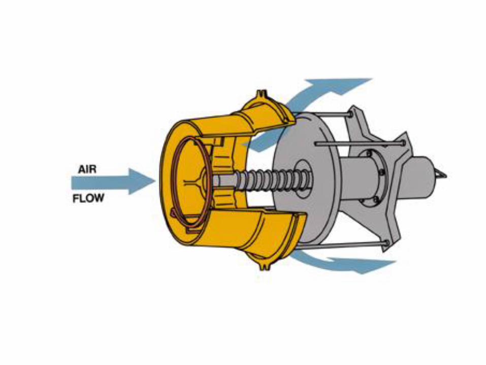
Air Valve
• Bevelled, self-centering damper w/Al cast inlet- even airflow/quiet operation- low leak, less than 1% leakage @ 4”
• Integral electric/pneumatic actuator- nothing to get out of adjustment- not exposed to jobsite abuse
• Patented multi-point/axis sensing flow ring- linear airflow characteristics- stable control for all inlet configuration


Air Valve
damper actuator
airflow

VAV Terminal Units
• terminal heating coil
• filter
• terminal mixing fan
primaryair
supplyair
airflowmodulationdevice

Air Valve
• Bevelled, self-centering damper w/Al cast inlet- even airflow/quiet operation- low leak, less than 1% leakage @ 4”
• Integral electric/pneumatic actuator- nothing to get out of adjustment- not exposed to jobsite abuse
• Patented multi-point/axis sensing flow ring- linear airflow characteristics- stable control for all inlet configuration


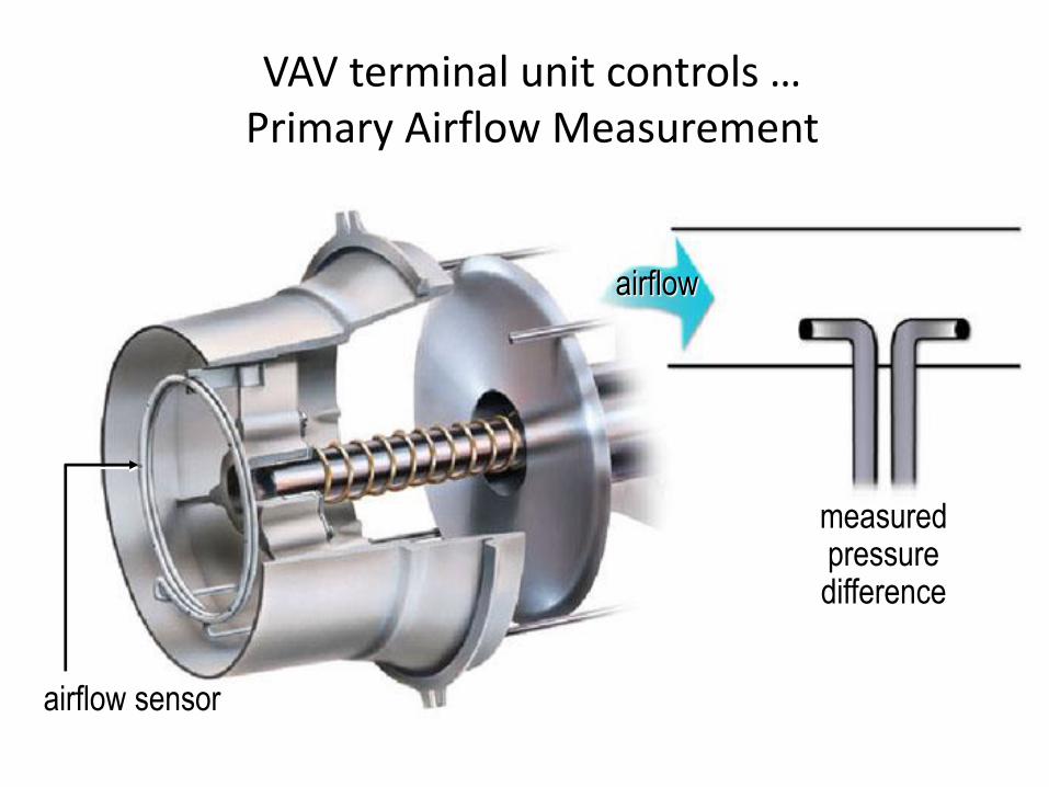
VAV terminal unit controls …Primary Airflow Measurement
measured pressuredifference
airflow
airflow sensor


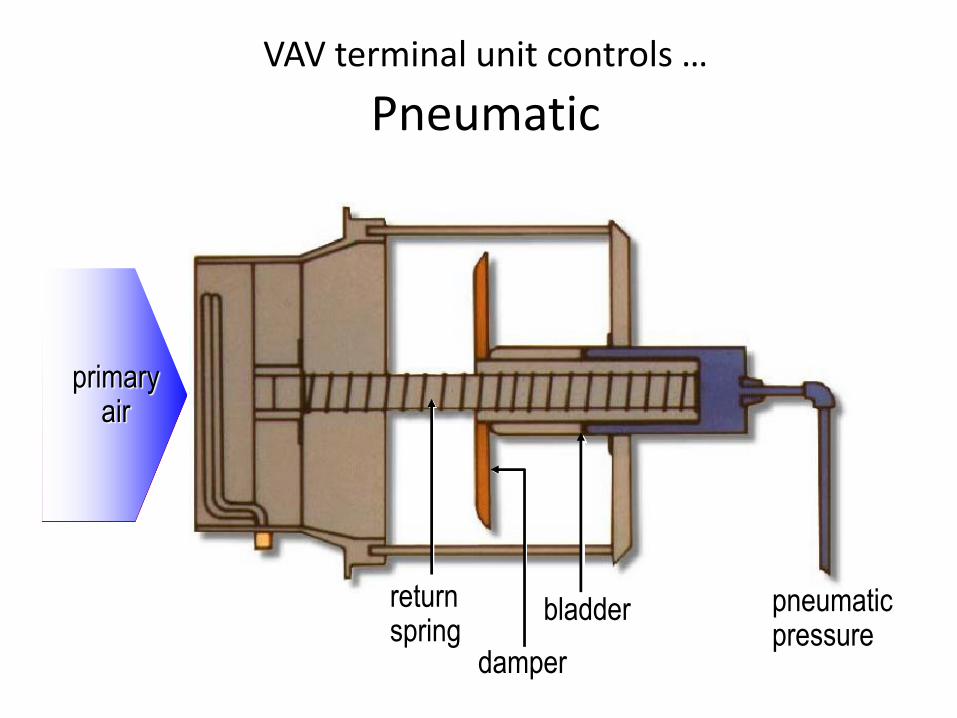
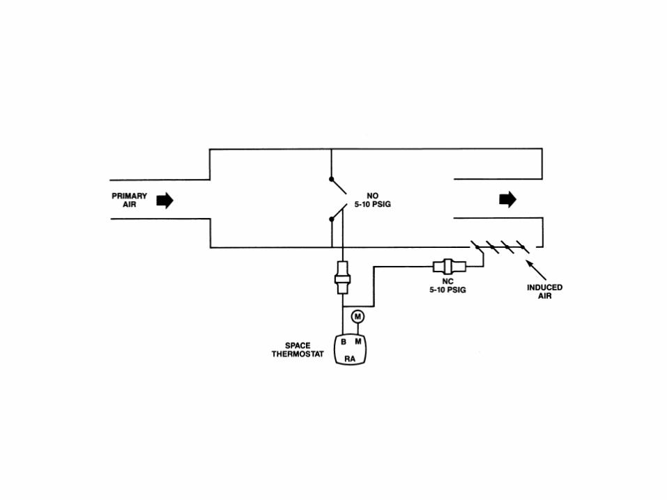
VAV terminal unit controls …
Pneumatic
damper
bladder pneumatic pressure
return spring
primary air
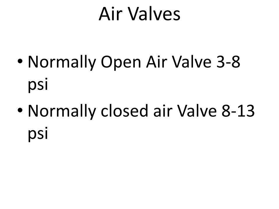
Air Valves
• Normally Open Air Valve 3-8 psi
• Normally closed air Valve 8-13 psi
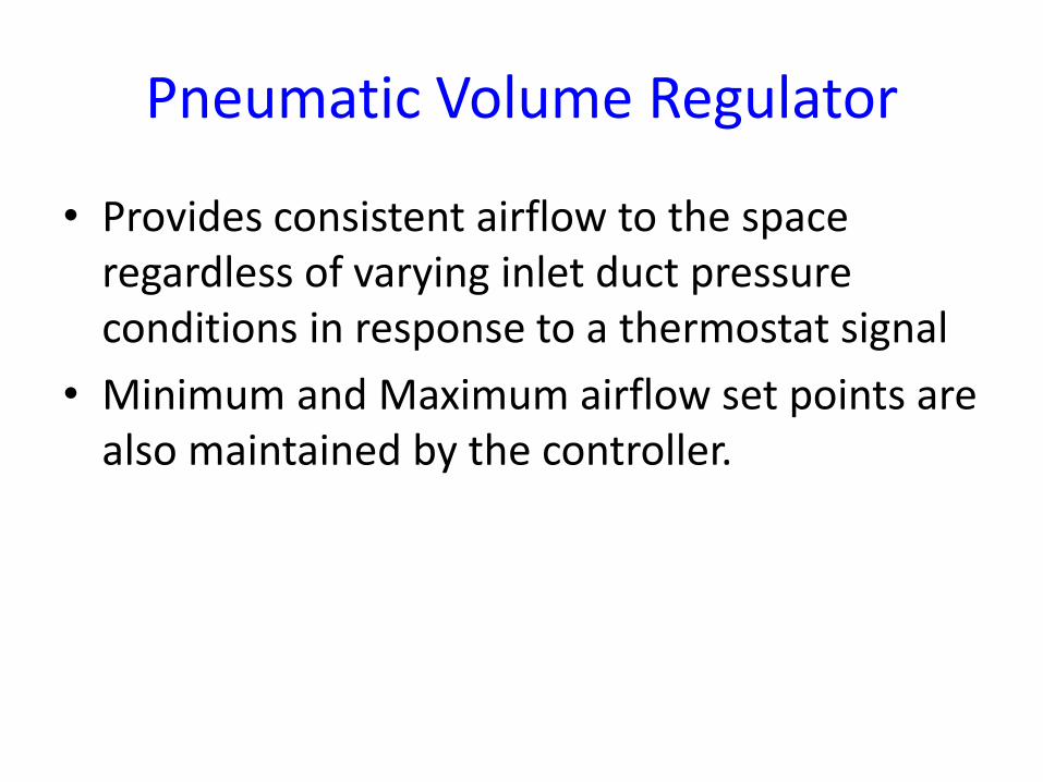
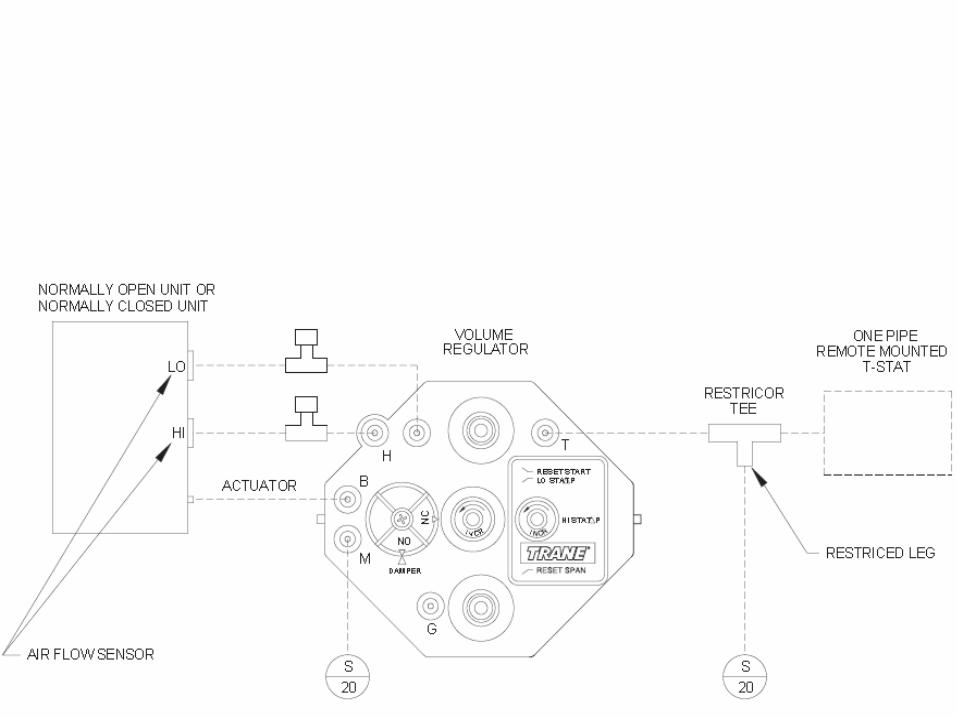
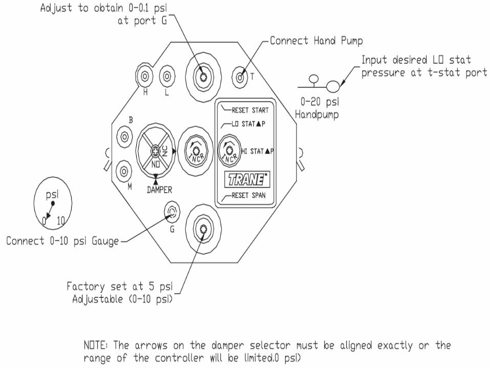
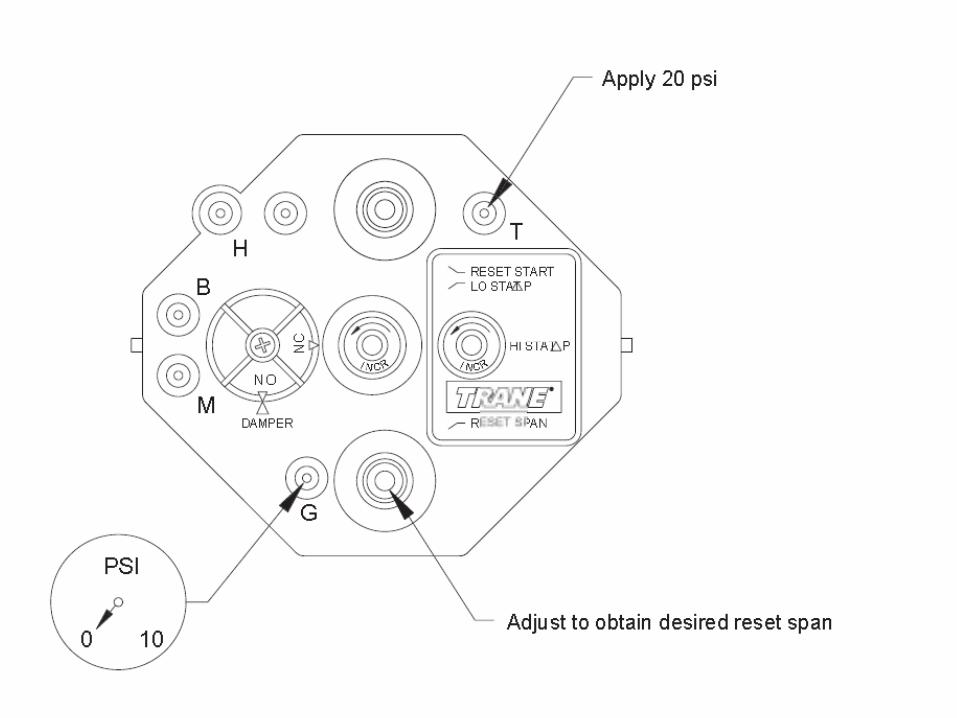
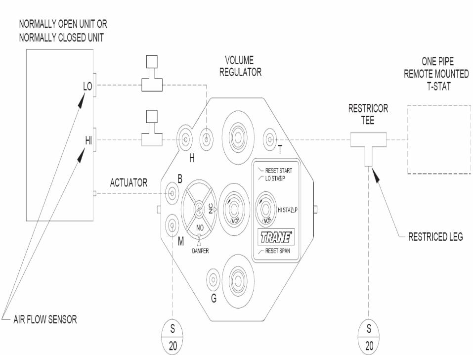
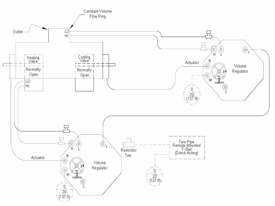
Pneumatic Volume Regulator
• Provides consistent airflow to the space regardless of varying inlet duct pressure conditions in response to a thermostat signal
• Minimum and Maximum airflow set points are also maintained by the controller.

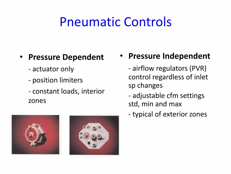
Pneumatic Controls
• Pressure Dependent
- actuator only
- position limiters
- constant loads, interior zones
• Pressure Independent
- airflow regulators (PVR) control regardless of inlet sp changes
- adjustable cfm settings std, min and max
- typical of exterior zones


X=High
Y=Low


VAV terminal unit controls …
Pneumatic
• Pneumatic Volume Regulator (PVR) provides pressure-independent control
• Pneumatic thermostat directly controls terminal unit fan and heat source
• Minimum and maximum airflow settings adjusted physically on PVR
• Compressed air operates modulation device, PVR and space thermostat

Reversing Relay
• A pneumatic reversing relay is a proportional non bleeding device that reverses an input signal based upon a pre-set constant.
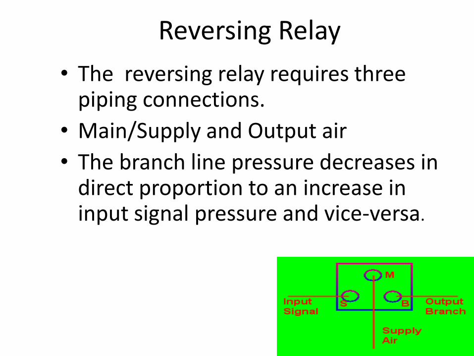
Reversing Relay
• The reversing relay requires three piping connections.
• Main/Supply and Output air
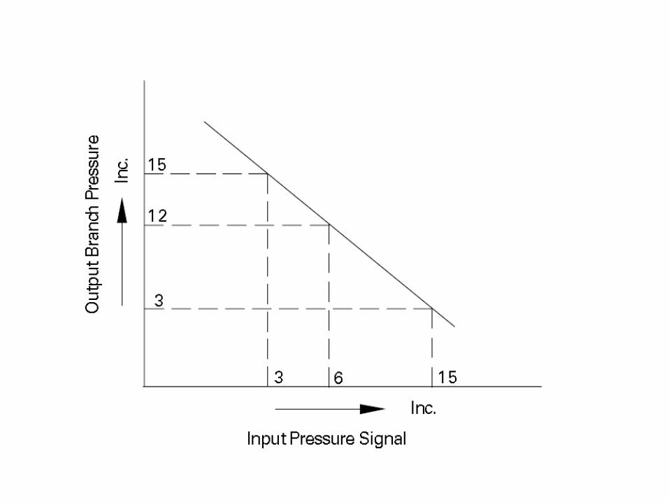
• The branch line pressure decreases in direct proportion to an increase in input signal pressure and vice-versa.


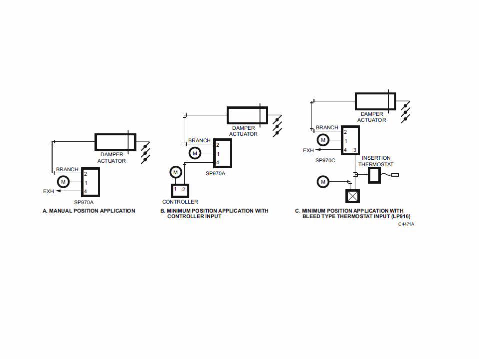
Signal Limiter
• The signal limiter is a pneumatic device that limits the pneumatic pressure signal to the air valve.Air flow delivery from the air valve is limited by the valve position and duct work static pressure
• Typically used on a system without a pneumatic volume regulator .Air flow through the air valve is pressure dependent.
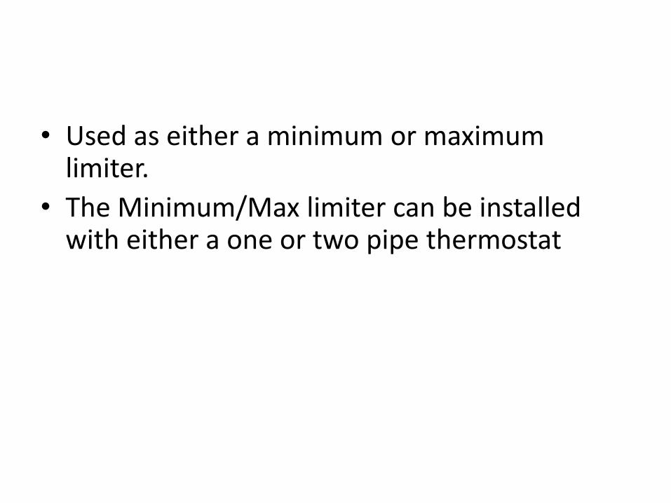
Signal Limiter• Used as either a minimum or maximum
limiter.
• The Minimum/Max limiter can be installed with either a one or two pipe thermostat
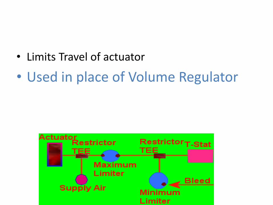
Signal Limiter (Min-Max)
• Limits Travel of actuator
• Used in place of Volume Regulator

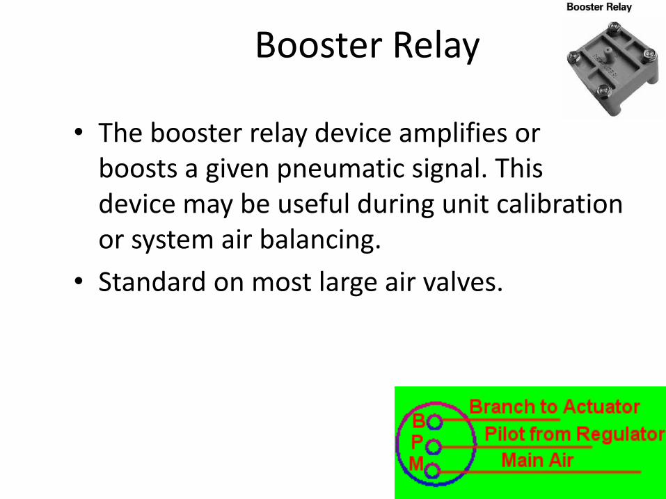
Booster Relay
• The booster relay device amplifies or boosts a given pneumatic signal. This device may be useful during unit calibration or system air balancing.
• Standard on most large air valves.
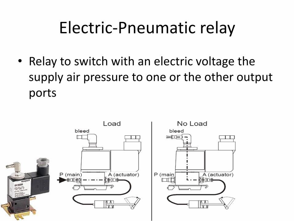
Electric-Pneumatic relay
• Relay to switch with an electric voltage the supply air pressure to one or the other output ports
B M
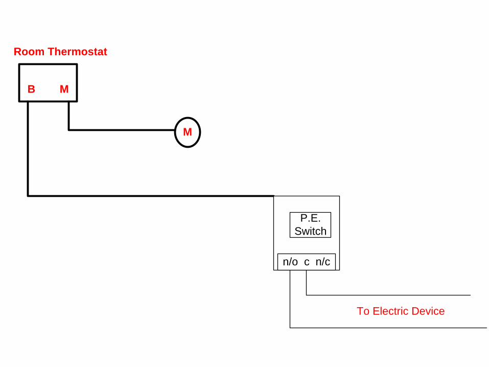
Room Thermostat
M
N
P.E.
Switch
n/o c n/c
To Electric Device


Pneumatic Selector Relay
• Thee-port relay to transmit the higher of two input signals

5
3
2
Relay
5
3
2
Relay
M
5 #
3 #
5 #10 #
10 #
Hi Selector Relay

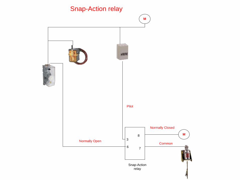
Pneumatic Snap Action Relay
• The four port, snap action relay converts a proportional air pressure change from a controller to a positive (two-position) Pressure change. It can also divert a supply line to one of two branches.
3
6
Snap-Action
relay
M8
7
M
Snap-Action relay
CommonNormally Open
Normally Closed
Pilot
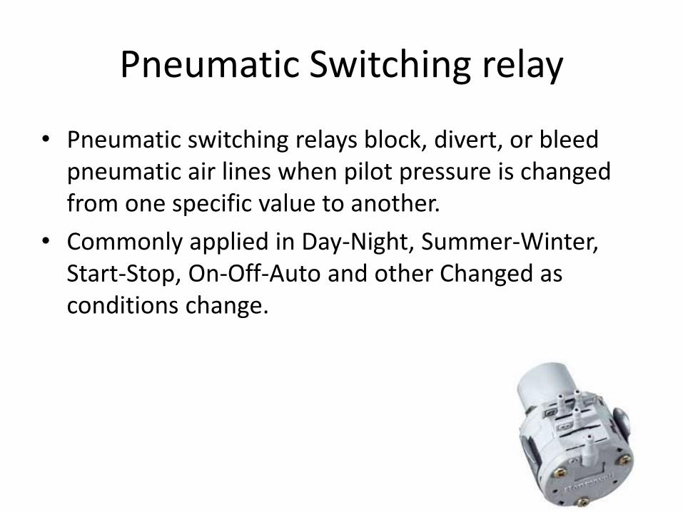
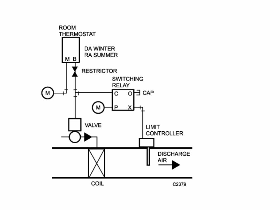
Pneumatic Switching relay
• Pneumatic switching relays block, divert, or bleed pneumatic air lines when pilot pressure is changed from one specific value to another.
• Commonly applied in Day-Night, Summer-Winter, Start-Stop, On-Off-Auto and other Changed as conditions change.
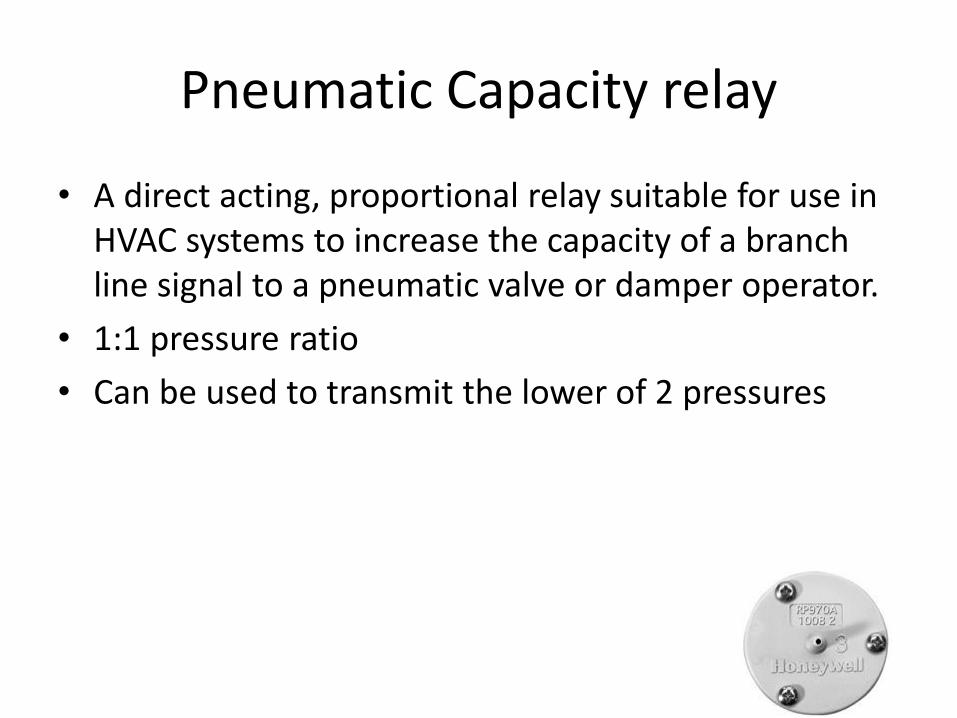
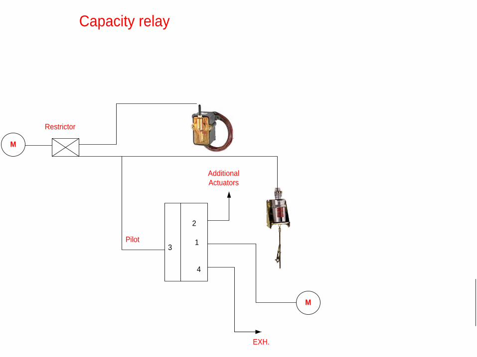
Pneumatic Capacity relay
• A direct acting, proportional relay suitable for use in HVAC systems to increase the capacity of a branch line signal to a pneumatic valve or damper operator.
• 1:1 pressure ratio
• Can be used to transmit the lower of 2 pressures
3
4
M
2
1
Capacity relay
EXH.
Additional
Actuators
Pilot
Restrictor
M
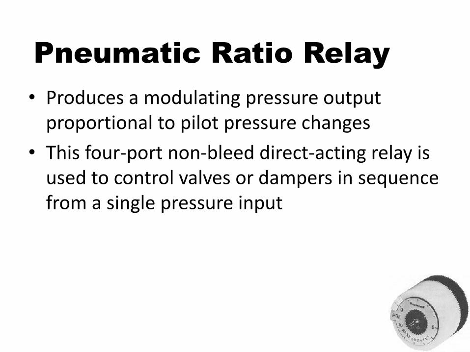
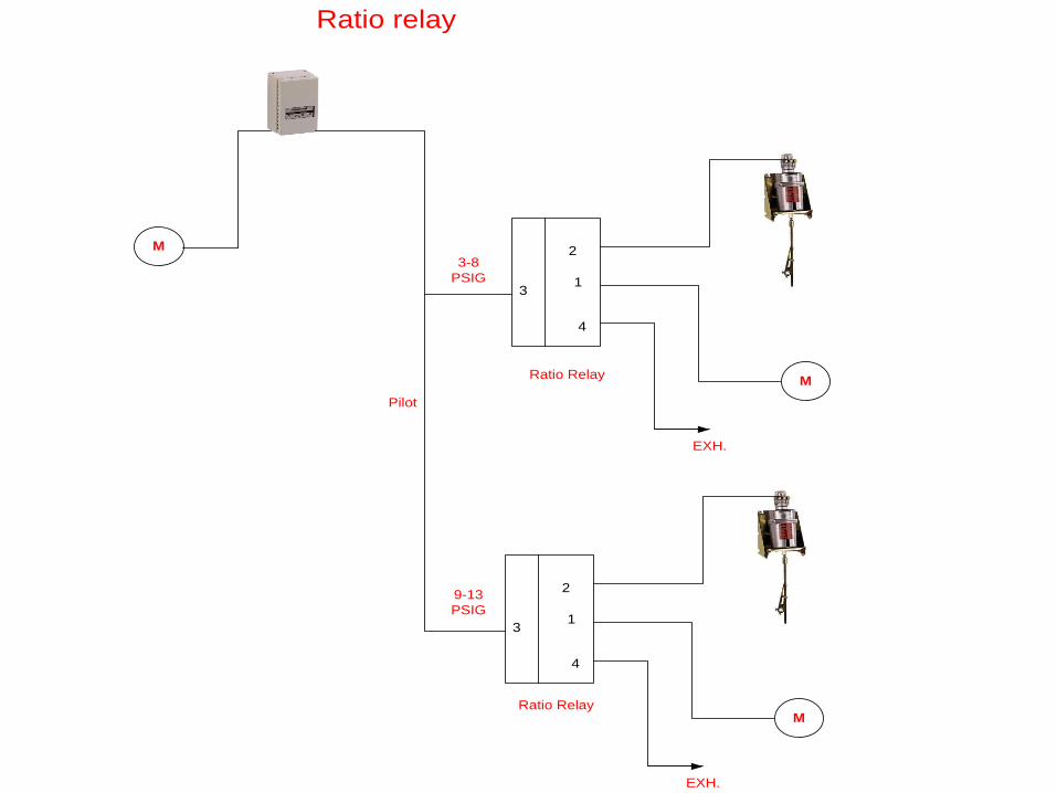
Pneumatic Ratio Relay
• Produces a modulating pressure output proportional to pilot pressure changes
• This four-port non-bleed direct-acting relay is used to control valves or dampers in sequence from a single pressure input
3
4
M
2
1
Ratio relay
EXH.
Pilot
M
3
4
Ratio Relay
2
1
EXH.
M
Ratio Relay
3-8
PSIG
9-13
PSIG
Pneumatic Potentiometer
• Three port pneumatic potentiometer can sum two input pressures average two input pressures, be an adjustable flow restriction, or be an adjustable pressure supply.
