pneumatic tyres for light trucks review public on standard ... · pneumatic tyres for light trucks...
TRANSCRIPT

DRAFT UGANDA S
TANDARD ON P
UBLIC R
EVIEW
DRAFT UGANDA
STANDARD
DUS EAS 359
First Edition 2015-mm-dd
Reference number DUS EAS 359: 2004
© UNBS 2015
Pneumatic tyres for light trucks — Specification
DRAFT UGANDA S
TANDARD ON P
UBLIC R
EVIEW
DUS EAS 359:2004
ii © UNBS 2015 - All rights reserved
Compliance with this standard does not, of itself confer immunity from legal obligations
A Uganda Standard does not purport to include all necessary provisions of a contract. Users are responsible for its correct application
© UNBS 2015
All rights reserved. Unless otherwise specified, no part of this publication may be reproduced or utilised in any form or by any means, electronic or mechanical, including photocopying and microfilm, without prior written permission from UNBS.
Requests for permission to reproduce this document should be addressed to
The Executive Director Uganda National Bureau of Standards P.O. Box 6329 Kampala Uganda Tel: 256 41 505 995 Fax: 256 41 286 123 E-mail: [email protected] Web: www.unbs.go.ug

DRAFT UGANDA S
TANDARD ON P
UBLIC R
EVIEW
DUS EAS 359:2004
© UNBS 2015 - All rights reserved iii
National foreword
Uganda National Bureau of Standards (UNBS) is a parastatal under the Ministry of Trade, Industry and Cooperatives established under Cap 327, of the Laws of Uganda, as amended. UNBS is mandated to co-ordinate the elaboration of standards and is (a) a member of International Organisation for Standardisation (ISO) and
(b) a contact point for the WHO/FAO Codex Alimentarius Commission on Food Standards, and
(c) the National Enquiry Point on TBT Agreement of the World Trade Organisation (WTO).
The work of preparing Uganda Standards is carried out through Technical Committees. A Technical Committee is established to deliberate on standards in a given field or area and consists of representatives of consumers, traders, academicians, manufacturers, government and other stakeholders.
Draft Uganda Standards adopted by the Technical Committee are widely circulated to stakeholders and the general public for comments. The committee reviews the comments before recommending the draft standards for approval and declaration as Uganda Standards by the National Standards Council. This Draft Uganda Standard, DUS EAS 359: 2004, Pneumatic tyres for light trucks — Specification, is identical with and has been reproduced from an East African Standard, EAS 359: 2004, Pneumatic tyres for light trucks — Specification, and is being proposed for adoption as a Uganda Standard.
This standard cancels and replaces US 515:2004, Specification for new pneumatic tyres — Light trucks .
This Uganda Standard, DUS EAS 359: 2004, has been developed by the Transport and communication standards Technical Committee (UNBS/TC 8).
Wherever the words, “East African Standard" appear, they should be replaced by "Uganda Standard."
DRAFT UGANDA S
TANDARD ON P
UBLIC R
EVIEW
EAS 359:2004 ICS 83.160.10
HS 4011.20; HS 4011.20.10 (radial) HS 4011.20.90 (other)
© EAC 2004 First Edition 2004
EAST AFRICAN STANDARD Pneumatic tyres for light trucks — Specification
EAST AFRICAN COMMUNITY

DRAFT UGANDA S
TANDARD ON P
UBLIC R
EVIEW
EAS 359:2004
ii © EAC 2004 — All rights reserved
Foreword Development of the East African Standards has been necessitated by the need for harmonizing requirements governing quality of products and services in East Africa. It is envisaged that through harmonized standardization, trade barriers which are encountered when goods and services are exchanged within the Community will be removed.
In order to achieve this objective, the Partner States in the Community through their National Bureaux of Standards, have established an East African Standards Committee.
The committee is composed of representatives of the National Standards Bodies in Partner States, together with the representatives from the private sectors and consumer organizations. Draft East African Standards are circulated to stakeholders through the National Standards Bodies in the Partner States. The comments received are discussed and incorporated before finalization of standards, in accordance with the procedures of the Community.
East African Standards are subject to review, to keep pace with technological advances. Users of the East African Standards are therefore expected to ensure that they always have the latest versions of the standards they are implementing.
© East African Community 2004 — All rights reserved*
East African Community
P O Box 1096
Arusha
Tanzania
Tel: 255 27 2504253/8
Fax: 255-27-2504481/2504255
E-Mail: [email protected]
Web: www.each.int
*
© 2004 EAC — All rights of exploitation in any form and by any means reserved worldwide for EAC Partner States’ NSBs.

DRAFT UGANDA S
TANDARD ON P
UBLIC R
EVIEW
EAS 359:2004
© EAC 2004 — All rights reserved iii
Introduction This East African Standardhas been prepared in order to give the necessary specifications and requirements for test of pneumatic tyres. It provides important information to be observed for improvement of motor vehicle safety in the country. In reporting the results of a test made in accordance with this East African Standard, if the final value, observed or calculated is to be rounded off, it shall be done in accordance with EAS 124. In the preparation of this East African Standard, assistance has been derived from the following documents: BS AU 50-1.2.1a:1995, Tyres and wheels — Specification for metric series tyres — Commercial vehicle tyres, published by the British Standards Institution. ISO 4209-1:2001, Truck and bus tyres and rims (metric series) — Part 1: Tyres ISO 10454, Truck and bus tyres — Verifying tyre capabilities — Laboratory test methods.

DRAFT UGANDA S
TANDARD ON P
UBLIC R
EVIEW
EAS 359:2004
iv © EAC 2004 — All rights reserved

DRAFT UGANDA S
TANDARD ON P
UBLIC R
EVIEW
EAST AFRICAN STANDARD EAS 359:2004
© EAC 2004 — All rights reserved 1
Pneumatic tyres for light trucks — Specification 1 Scope This East African Standard specifies tyre dimensions, designation, marking requirements and load ratings. It also gives laboratory test requirements for bead unseating, strength and endurance performance for light truck tyres. This East African Standard also specifies sampling methods and disposition of non conforming tyres. 2 Application This East African Standard applies to all pneumatic light truck tyres with both “tube type and tubeless” of radial and bias constructions. It does not apply to any tyre that has been reconditioned or altered so as to render it impossible for use or repaired for use as part of motor vehicle equipment. For the purposes of this East African Standard, light truck tyre is considered to be a tyre for commercial and light truck vans with carrying capacity of up to 1 — 5 tons, ply rating from 6 — 14, rim size form 10” — 17.5” and load index from 81 — 144 (for radial tyres having description suffix “C”). 3 Normative references ISO 4223-1, Definitions of some terms used in the tyre industry — Part 1: Pneumatic tyres ISO 10191:1995 – TW – 2B/4, Methods of test for verifying tyre capabilities, published by the International Organization for Standardization BS AU 50-1.2.4:1994, Method of test for verifying tyre capabilities, published by the British Standard Automobile Series ETRTO Standard manual:2001, Standards for tyres / rims/ valves for ground vehicles — The European tyre and rim technical organization (E.T.R.T.O.) ETRTO Engineering design information:2001, The European tyre and rim technical organization E.T.R.T.O. Design guides and engineering data JATMA year book (tyres standards):2001 The Japan automobile tyre manufacturers association, Inc EAS 357, Pneumatic tyres for trucks and buses — Specification EAS 124, Rounding off numerical values The tyre and rim association inc. year book: 2000 – TRA manual 4 Terminology For the purposes of this East African Standard, the following definitions shall apply: 4.1 approved rim contour an Approved rim contour is one agreed by ETRTO/ TRA/JATMA members for use with a specific tyre size designation 4.2 bead that part of the tyre which is shaped to fit the rim. It has a core made of one or several essentially inextensible strands with the plies wrapped around the core

DRAFT UGANDA S
TANDARD ON P
UBLIC R
EVIEW
EAS 358:2004
2 © EAC 2004 — All rights reserved
4.3 bead flange and bead seat the parts of the rim which support the tyre 4.4 bead separation breakdown of bond between components in the bead area 4.5 belt or bracing ply – radial tyre a layer of material underneath the tread, laid substantially in the direction of the tread center-line that restricts the carcass in a circumferential direction 4.6 bias belted tyre a pneumatic tyre structure of bias ply (diagonal) type the carcass being restricted by a substantially inextensible circumferential belt – construction code “B” 4.7 bias ply tyre a pneumatic tyre in which the ply cords that extend form the beads and are laid at alternate angles substantially less than 90° to the centerline of tread- construction code “B” 4.8 beaker- diagonal tyre an intermediate ply between carcass and tread centerline of the tread 4.9 carcass the rubber- bonded cord structure of a tyre integral with bead, which contains the inflation pressure 4.10 chunking breaking away of pieces of the thread 4.11 cord textile or non – textiles strands (threads) used in various components of the tyre carcass, plies, belt, breakers, etc 4.12 cord separation cord parting from adjacent rubber compounds 4.13 cracking any parting within the tread, sidewall or innerliner of the tyre extending to cord material 4.14 cyclic service condition marked on earthmoving equipment tyres in ‘transport and /or loading’
4.15 design tyre dimension the figures or values used for tyre design purposes
4.16 diagonal (bias ply) tyre describes a pneumatic tyre structure in which the ply cords extend to the beads and are laid at alternate angles substantially less than 90° to the centerline of the tread - construction code “D” or “-“

DRAFT UGANDA S
TANDARD ON P
UBLIC R
EVIEW
EAS 359:2004
© EAC 2004 — All rights reserved 3
4.17 groove the space between two adjacent tread ribs 4.18 grown Tyre a tyre which has undergone expansion due to use in service 4.19 gutter the groove in the rim base in which the rim parts, such as the spring lock ring or detachable spring flange, fit and are retained buy the gutter tip 4.20 implement Tyres designed primarily for agricultural machines or implements (vehicles in category S) or for agricultural trailers (vehicles in category R). However they may also equip either front steering wheels and drive wheels of agricultural and forestry tractors (vehicles in category S). They are not suitable for sustained high torque service 4.21 innerliner the layers forming the inside surface of a tubeless tyre that contains the inflating medium within the tyre 4.22 innerliner separation parting of innerliner from cord material in the carcass 4.23 inflation pressure the pressure taken with the tyre at ambient temperature and does not include any pressure build up due to tyre usage 4.24 load capacity the maximum load a tyre is permitted to carry under specified operating conditions 4.25 load index a numerical code associated with the maximum load a tyre can carry at the speed indicated by its speed symbol under service conditions specified by the tyre manufacturer 4.26 ply rating an index of casing strength, not necessarily representing number of cord plies in a tyre 4.27 maximum overall (grown) diameter in service dC,) the maximum overall diameter plus manufacturing tolerances and tolerances for service growth 4.28 maximum tyre dimensions in service inflated tyre dimensions including permanent growth in service 4.29 maximum load rating maximum load that the tyre is rated to carry in single formation at the reference speed

DRAFT UGANDA S
TANDARD ON P
UBLIC R
EVIEW
EAS 358:2004
4 © EAC 2004 — All rights reserved
4.30 maximum permissible inflation pressure maximum cold inflation pressure to which a tyre may be inflated. It does not include build up due to tyre usage 4.31 measuring rim the rim specified by the relevant sub – committee for the measurement of the tyre 4.32 measuring rim width linear distance between the rim flanges of the measuring rim 4.33 moped (or cyclomoteur or ciclomotore) motorcycle tyres designed for motorcycles having a speed capability less than or 50 km/h 4.34 new tyre a tyre which has neither been used nor subjected to retreading operation 4.35 nominal aspect ratio one hundred times the ratio of the section height to the section width of the tyre on its theoretical rim 4.36 nominal aspect ratio design one hundred times the ratio of the design section height to the nominal section width (h/s). For some existing code designated series the value shown is only approximate 4.37 nominal rim diameter the nominal rim diameter is a size code figure for reference purposes only, as indicated in the tyre and rim size designation 4.38 nominal section width the section width of an inflated tyre mounted on its theoretical rim and indicated in the tyre size designation 4.39 not for highway use (NHS) motorcycle tyres designed for off-the-road applications. They must not be used on the public highway 4.40 open splice any parting at any junction of tread, sidewall or innerliner that extends to cord material 4.41 overall diameter the diameter of an inflated tyre at the outermost surface of the tread 4.42 overall width the linear distance between the outsides of the sidewalls of an inflated tyre including elevations due to labeling (markings), decorations, and protective bands or ribs 4.43 ply a layer of rubber - coated parallel cords.

DRAFT UGANDA S
TANDARD ON P
UBLIC R
EVIEW
EAS 359:2004
© EAC 2004 — All rights reserved 5
4.44 ply separation parting of rubber compound between adjacent plies. 4.45 play rating index of tyre strength often designated as PR 4.46 pneumatic tyre a mechanical device made out of rubber, chemicals, fabric and steel or other material, which when mounted on an automotive wheel provides traction and contains the gas or fluid that sustains the total load 4.47 radial ply tyre a pneumatic tyre in which the ply cords extend to the beads and are laid substantially at 90 degrees to the centerline of the tread 4.48 regroovable commercial vehicle tyres designed with sufficient undertread to allow a subsequent re-grooving of the original tread pattern 4.49 reinforced (or REINF) passenger car tyres and/or motorcycle tyres designed for loads and inflation pressures higher than the standard version 4.50 retreaded tyre a tyre to which a new tread has been applied to extend the useful life of the tyre 4.51 rim that part of the wheel on which the tyre or tyres and tube assembly is mounted and supported 4.52 rim width the linear distance between the flanges of the rim 4.53 road service description marked on radial construction earthmoving equipment tyres in highway service 4.54 section height half the difference between the overall diameter and the nominal rim diameter 4.55 section width the linear distance between the outsides of the sidewalls of an inflated tyre excluding elevations due to labeling (markings), decorations, or protective bands or ribs 4.56 service description in addition to the Tyre Size Designation, a tyre may be identified by a Service Description consisting of a load index (or two load indices in the case of single/dual fitments) and a speed symbol

DRAFT UGANDA S
TANDARD ON P
UBLIC R
EVIEW
EAS 358:2004
6 © EAC 2004 — All rights reserved
4.57 sidewall the part of the pneumatic tyre between the tread and the bead 4.58 sidewall rubber the rubber layer on the sidewall of the tyre and over the carcass, which may include ornamental or protective ribs and fittings lines 4.59 sidewall separation parting of the rubber compound from the cord material in the sidewall 4.60 size factor the sum of the section width and the outer diameter of a tyre determined on the test rim 4.61 special tread tyre (ET) tyre whose tread pattern is primarily designed to provide satisfactory performance under special service conditions (e.g. mixed, use, on and off-road, city bus, etc.) 4.62 specified rim diameter the diameter at the intersection of the planes of the rim bead seat and the rim flange depending on the rim design, it can be either smaller or larger than the nominal rim diameter 4.63 speed category a code indicating tyre speed capabilities 4.64 solid rubber solid tyres for pneumatic tyre rims 4.65 temporary use only passenger car tyres intended for temporary use as a spare in one position only 4.66 test rim any rim on which the tyre may be fitted that conforms to the dimensions of the recommended rims for the particular tyre designation and type 4.67 test drum speed peripheral speed of the test drum 4.68 tread rib a tread section that runs circumferentially around the tyre 4.69 tread separation pulling away of the tread from the tyre carcass 4.70 theoretical rim a rim having a width of specified ratio to the nominal section width

DRAFT UGANDA S
TANDARD ON P
UBLIC R
EVIEW
EAS 359:2004
© EAC 2004 — All rights reserved 7
4.71 tread the part of a pneumatic tyre which normally comes in contact with the ground / road 4.72 tubeless tyres specifically designed for fitment without an inner tube on appropriate rims 4.73 tyre measurement measurements taken on the unloaded tyre mounted on its measuring rim at the recommended inflation pressure and conditioning 4.74 valve aperture the hole or slot in the rim which accommodates the valve for tyre inflation 4.75 wheel a rotating load carrying member between the tyre and the axle, usually consisting of two major parts, the rim and the wheel center 4.76 well that part of the rim so located with sufficient depth and width to enable the beads to be mounted and dismounted over the mounting side rim flange or bead seat taper Tyre codes used in tyre industries 4.77 C commercial vehicle tyres for service on light duty vehicles 4.78 CT special design passenger car tyres suitable for fitment on CT rim only 4.79 DP tyres specifically designed for mud and snow (Winter). MS, M&S, M.S and M-S or M+S are also used 4.80 extra load (or XL) passenger car tyres and/or motor- cycle tyres designed for loads and inflation pressures higher than the standard version 4.81 S tyre intended for temporary use as spare (no more than one in use at a time) 4.82 T tyres intended for temporary use as a spare, in one position only at a time, with inflation pressures higher than those of Standard or Reinforced tyres 4.83 * symbols used to identify different versions load capacity/ inflation pressure of earthmoving equipment tyres in radial construction
DRAFT UGANDA S
TANDARD ON P
UBLIC R
EVIEW
EAS 358:2004
8 © EAC 2004 — All rights reserved
4.84 FRT commercial vehicle tyres restricted to the equipment of non-driven axles, excluding motor vehicle front steering axles 4.85 IMP tyres designed primarily for agricultural machines or implements 4.86 M/C motorcycle tyres which are designed for use on M/C motorcycle rims having a bead seat diameter which differs from that of rims with the same designation, designed for passenger car, commercial vehicles and agricultural applications 4.87 M+S tyres specifically designed for mud and snow (Winter). MS, M&S, M.S and M-S or DP are also used 4.88 IND agricultural tyres for traction wheels for construction applications, with load capacities and inflation pressures which differ from those for tyres with the same size designation for use on agricultural tractors 4.89 MPT commercial vehicle tyres for service on multipurpose trucks 4.90 MST motorcycle tyres designed for special service having a wider tread than equivalent sizes with the same tyre size designation 4.91 PR identifies different versions (load capacity/inflation pressure) of tyres having the same size designation 4.92 TG (or GRADER) existing diagonal construction grader service tyres 5 General requirements 5.1 Materials The basic compound used in the construction, shall be of natural rubber, synthetic rubber or a combination thereof. 5.2 Ozone resistance Each tyre as part of production shall contain sufficient anti-oxidants and anti-ozonants to provide standard commercial resistance to weathering. 5.3 Temperature ability Each tyre shall have an inherent capability of acceptable performance in ambient air temperature ranging from -5 °C to 50 °C.
DRAFT UGANDA S
TANDARD ON P
UBLIC R
EVIEW
EAS 359:2004
© EAC 2004 — All rights reserved 9
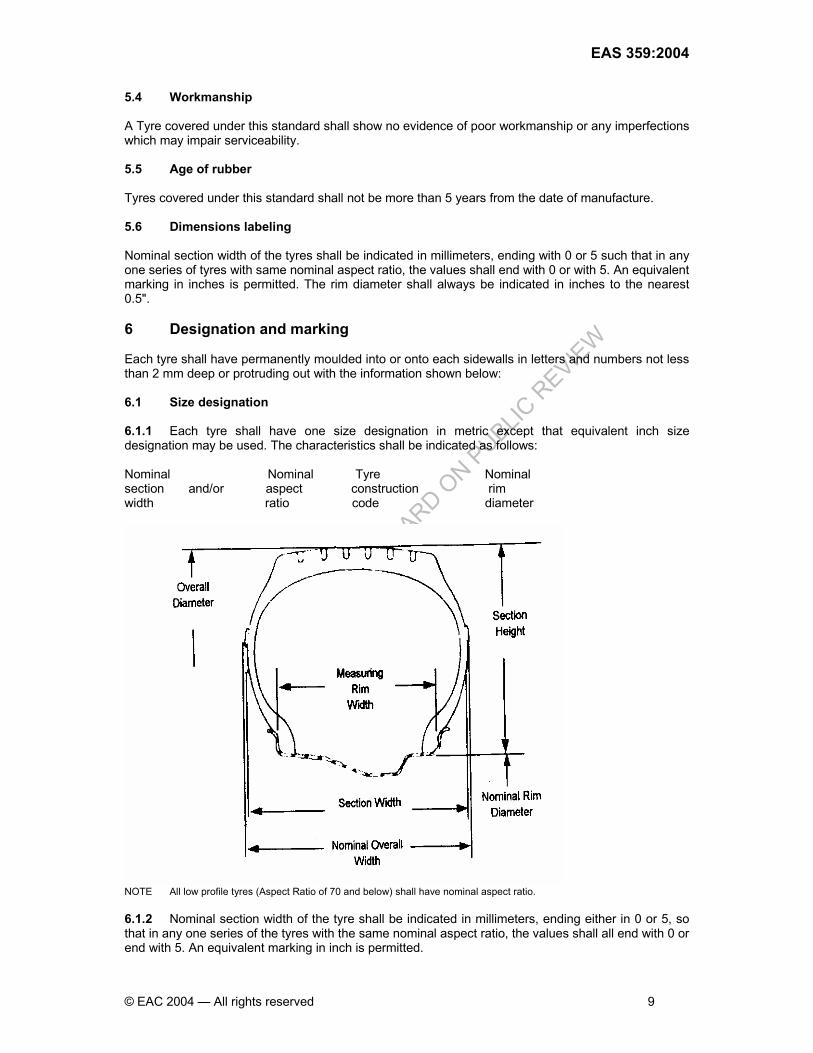
5.4 Workmanship A Tyre covered under this standard shall show no evidence of poor workmanship or any imperfections which may impair serviceability. 5.5 Age of rubber Tyres covered under this standard shall not be more than 5 years from the date of manufacture. 5.6 Dimensions labeling Nominal section width of the tyres shall be indicated in millimeters, ending with 0 or 5 such that in any one series of tyres with same nominal aspect ratio, the values shall end with 0 or with 5. An equivalent marking in inches is permitted. The rim diameter shall always be indicated in inches to the nearest 0.5". 6 Designation and marking Each tyre shall have permanently moulded into or onto each sidewalls in letters and numbers not less than 2 mm deep or protruding out with the information shown below: 6.1 Size designation 6.1.1 Each tyre shall have one size designation in metric except that equivalent inch size designation may be used. The characteristics shall be indicated as follows: Nominal Nominal Tyre Nominal section and/or aspect construction rim width ratio code diameter
NOTE All low profile tyres (Aspect Ratio of 70 and below) shall have nominal aspect ratio. 6.1.2 Nominal section width of the tyre shall be indicated in millimeters, ending either in 0 or 5, so that in any one series of the tyres with the same nominal aspect ratio, the values shall all end with 0 or end with 5. An equivalent marking in inch is permitted.
DRAFT UGANDA S
TANDARD ON P
UBLIC R
EVIEW
EAS 358:2004
10 © EAC 2004 — All rights reserved
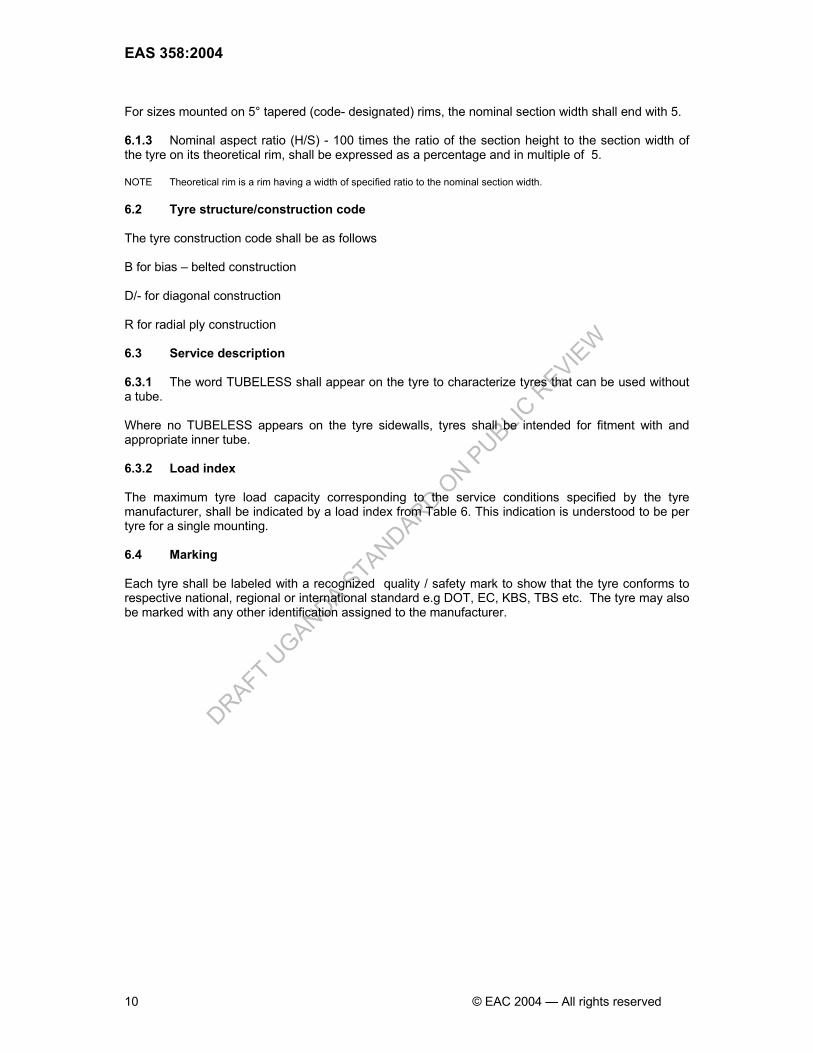
For sizes mounted on 5° tapered (code- designated) rims, the nominal section width shall end with 5. 6.1.3 Nominal aspect ratio (H/S) - 100 times the ratio of the section height to the section width of the tyre on its theoretical rim, shall be expressed as a percentage and in multiple of 5. NOTE Theoretical rim is a rim having a width of specified ratio to the nominal section width. 6.2 Tyre structure/construction code The tyre construction code shall be as follows B for bias – belted construction D/- for diagonal construction R for radial ply construction 6.3 Service description 6.3.1 The word TUBELESS shall appear on the tyre to characterize tyres that can be used without a tube. Where no TUBELESS appears on the tyre sidewalls, tyres shall be intended for fitment with and appropriate inner tube. 6.3.2 Load index The maximum tyre load capacity corresponding to the service conditions specified by the tyre manufacturer, shall be indicated by a load index from Table 6. This indication is understood to be per tyre for a single mounting. 6.4 Marking Each tyre shall be labeled with a recognized quality / safety mark to show that the tyre conforms to respective national, regional or international standard e.g DOT, EC, KBS, TBS etc. The tyre may also be marked with any other identification assigned to the manufacturer.

DRAFT UGANDA S
TANDARD ON P
UBLIC R
EVIEW
EAS 359:2004
© EAC 2004 — All rights reserved 11
DRAFT UGANDA S
TANDARD ON P
UBLIC R
EVIEW
EAS 358:2004
12 © EAC 2004 — All rights reserved
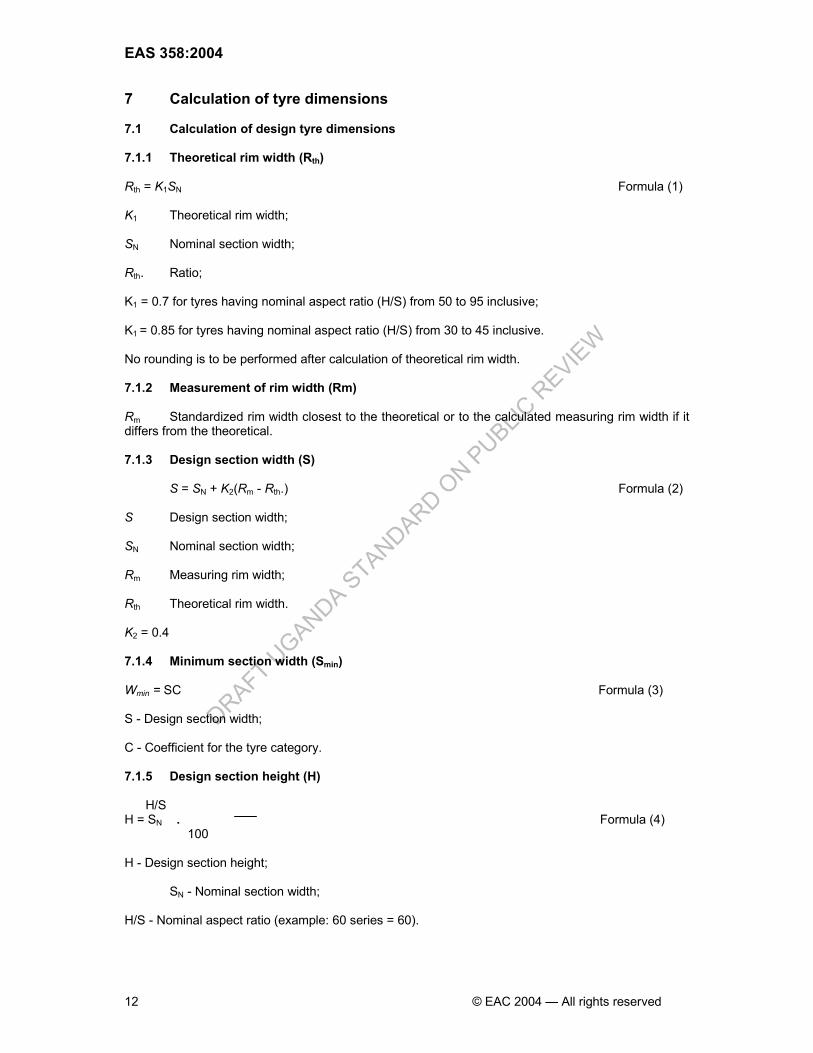
7 Calculation of tyre dimensions 7.1 Calculation of design tyre dimensions 7.1.1 Theoretical rim width (Rth) Rth = K1SN Formula (1) K1 Theoretical rim width; SN Nominal section width; Rth. Ratio; K1 = 0.7 for tyres having nominal aspect ratio (H/S) from 50 to 95 inclusive; K1 = 0.85 for tyres having nominal aspect ratio (H/S) from 30 to 45 inclusive. No rounding is to be performed after calculation of theoretical rim width. 7.1.2 Measurement of rim width (Rm) Rm Standardized rim width closest to the theoretical or to the calculated measuring rim width if it differs from the theoretical. 7.1.3 Design section width (S)
S = SN + K2(Rm - Rth.) Formula (2) S Design section width; SN Nominal section width; Rm Measuring rim width; Rth Theoretical rim width. K2 = 0.4 7.1.4 Minimum section width (Smin) Wmin = SC Formula (3) S - Design section width; C - Coefficient for the tyre category. 7.1.5 Design section height (H) H/S H = SN . Formula (4) 100 H - Design section height; SN - Nominal section width; H/S - Nominal aspect ratio (example: 60 series = 60).
DRAFT UGANDA S
TANDARD ON P
UBLIC R
EVIEW
EAS 359:2004
© EAC 2004 — All rights reserved 13
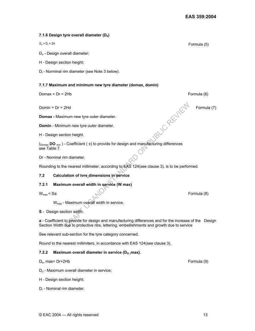
7.1.6 Design tyre overall diameter (D0)
Formula (5) Do - Design overall diameter; H - Design section height; Dr - Norminal rim diameter (see Note 3 below). 7.1.7 Maximum and minimum new tyre diameter (domax, domin) Domax = Dr = 2Hb Formula (6) Domin = Dr = 2Hd Formula (7) Domax - Maximum new tyre outer diameter. Domin - Minimum new tyre outer diameter. H - Design section height. (Domax DO min ) - Coefficient ( ±) to provide for design and manufacturing differences see Table 7. Dr - Nominal rim diameter. Rounding to the nearest millimeter, according to EAS 124(see clause 3), is to be performed. 7.2 Calculation of tvre dimensions in service 7.2.1 Maximum overall width in service (W max) Wmax = Sa Formula (8) Wmax - Maximum overall width in service. S - Design section width. a - Coefficient to provide for design and manufacturing differences and for the increase of the Design Section Width due to protective ribs, lettering, embellishments and growth due to service See relevant sub-section for the tyre category concerned. Round to the nearest millimiters, in accordance with EAS 124(see clause 3). 7.2.2 Maximum overall diameter in service (DO ,max). Do, max= Dr+2Hb Formula (9) Do - Maximum overall diameter in service; H - Design section height; Dr - Nominal rim diameter.

DRAFT UGANDA S
TANDARD ON P
UBLIC R
EVIEW
EAS 358:2004
14 © EAC 2004 — All rights reserved
Rounding to the nearest millimeter, in accordance with EAS 124,is to be performed after final calculation. 7.2.3 Maximum section height in service(H)

DRAFT UGANDA S
TANDARD ON P
UBLIC R
EVIEW
EAS 359:2004
© EAC 2004 — All rights reserved 15
8 Test requirements 8.1 Test sample Two tyres with identical characteristics, e.g. size designation and service description or maximum load rating, ply rating and speed capability, shall comprise a test sample. 8.1.1 One tyre shall be used for the measurement of physical dimensions, resistance to bead unseating and strength in sequence. 8.1.2 A second tyre for the endurance test. The pressures, loads, speeds and durations shall be as specified for each test method. Each test sample shall conform to the requirements specified in 6.2 to 6.5 as appropriate. 8.2 Test equipment The test equipment consists of 8.2.1 Test drum, cylindrical driven flywheel (drum having a diameter of 1.7 m ± 2 % or 2 m ± 2 %). The surface of the drum shall be smooth steel and the width of the test surface shall be equal to or exceed the overall width of the test tyre. For the test drum, the loading device shall have a capacity of at least 5700 kg and the accuracy shall be within ± 1 % of the full scale. For the test drum, the speed capability of the equipment shall be adequate for the requirements of the test methods. The accuracy of the test drum speed shall be within + 2 km/h to - 0 km/h. 8.2.2 Plunger, cylindrical steel plunger of sufficient length with a hemispherical end and of diameter as shown below:
Table 2 — Recommended pressures for measurement of tyre dimensions
Type Pressure kPa Standard load ap-type light load version 180
Extra load/reinforced version 220 T-type Temporary-use spare type 420
For the plunger equipment, the loading device shall permit gradual application of the force. Indicators of displacement and force provided shall have an accuracy within ± 1 % of full scale. For the plunger equipment, the displacement speed shall be controlled with an accuracy within ± 3 % of the full scale. 8.2.3 Bead unseating block The bead unseating block loading device shall permit progressive application of the force. Indicators of displacement and force provided shall have an accuracy ± 1 % of full scale. The displacement speed of the bead unseating block shall be controlled with an accuracy within ± 3 % of the full scale. 8.2.4 Inflation pressure gauges, with a maximum scale value of at least 500 kPa with an accuracy within ±1:5 k Pa. 8.3 Testing 8.3.1 Non destructive testing 8.3.1.1 Physical dimensions measurement The tyre physical dimensions shall be determined under uniform ambient conditions as follows:
DRAFT UGANDA S
TANDARD ON P
UBLIC R
EVIEW
EAS 358:2004
16 © EAC 2004 — All rights reserved
8.3.1.1.1 Tyre preparation The sample shall be mounted on a recommended test rim for that tyre size designation and inflated to the applicable pressures in single formation as shown in Tyre Dimension Table 2. Then the tyre shall be conditioned at ambient room temperature for a minimum of 24 h for bias construction and 3 h for radial construction. The pressure is then re-adjusted to the original value. 8.3.1.1.2 Test procedure a) The section width and overall width are callipered at six points approximately equally spaced
around the tyre circumference. The average of the measurements of the section width and overall width respectively is recorded.
b) The tyre overall diameter is determined by measuring the maximum circumference of the tyre
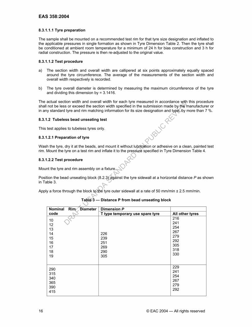
and dividing this dimension by = 3.1416. The actual section width and overall width for each tyre measured in accordance with this procedure shall not be less or exceed the section width specified in the submission made by the manufacturer or in any standard tyre and rim matching information for its size designation and type, by more than 7 %. 8.3.1.2 Tubeless bead unseating test This test applies to tubeless tyres only. 8.3.1.2.1 Preparation of tyre Wash the tyre, dry it at the beads, and mount it without lubrication or adhesive on a clean, painted test rim. Mount the tyre on a test rim and inflate it to the pressure specified in Tyre Dimension Table 4. 8.3.1.2.2 Test procedure Mount the tyre and rim assembly on a fixture. Position the bead unseating block (8.2.3) against the tyre sidewall at a horizontal distance P as shown in Table 3. Apply a force through the block to the tyre outer sidewall at a rate of 50 mm/min ± 2.5 mm/min.
Table 3 — Distance P from bead unseating block
Dimension P Nominal Rim Diameter code T type temporary use spare tyre All other tyres 10 12 13 14 15 16 17 18 19
226 239 251 269 290 305
216 241 254 267 279 292 305 318 330
290 315 340 365 390 415
229 241 254 267 279 292
DRAFT UGANDA S
TANDARD ON P
UBLIC R
EVIEW
EAS 359:2004
© EAC 2004 — All rights reserved 17
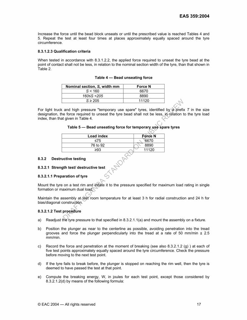
Increase the force until the bead block unseats or until the prescribed value is reached Tables 4 and 5. Repeat the test at least four times at places approximately equally spaced around the tyre circumference. 8.3.1.2.3 Qualification criteria When tested in accordance with 8.3.1.2.2, the applied force required to unseat the tyre bead at the point of contact shall not be less, in relation to the nominal section width of the tyre, than that shown in Table 2.
Table 4 — Bead unseating force
Nominal section, S, width mm Force N S < 160 6670
160≤S <205 8890 S ≥ 205 11120
For light truck and high pressure "temporary use spare" tyres, identified by a prefix T in the size designation, the force required to unseat the tyre bead shall not be less, in relation to the tyre load index, than that given in Table 4.
Table 5 — Bead unseating force for temporary use spare tyres
Load index Force N ≤75 6670
76 to 92 8890 ≥93 11120
8.3.2 Destructive testing 8.3.2.1 Strength test/ destructive test 8.3.2.1.1 Preparation of tyre Mount the tyre on a test rim and inflate it to the pressure specified for maximum load rating in single formation or maximum dual load. Maintain the assembly at test room temperature for at least 3 h for radial construction and 24 h for bias/diagonal construction. 8.3.2.1.2 Test procedure a) Readjust the tyre pressure to that specified in 8.3.2.1.1(a) and mount the assembly on a fixture. b) Position the plunger as near to the centerline as possible, avoiding penetration into the tread
grooves and force the plunger perpendicularly into the tread at a rate of 50 mm/min ± 2.5 mm/min.
c) Record the force and penetration at the moment of breaking (see also 8.3.2.1.2 (g) ) at each of
five test points approximately equally spaced around the tyre circumference. Check the pressure before moving to the next test point.
d) If the tyre fails to break before, the plunger is stopped on reaching the rim well, then the tyre is
deemed to have passed the test at that point. e) Compute the breaking energy, W, in joules for each test point, except those considered by
8.3.2.1.2(d) by means of the following formula:

DRAFT UGANDA S
TANDARD ON P
UBLIC R
EVIEW
EAS 358:2004
18 © EAC 2004 — All rights reserved
2000PFW ×
=
where F is the force, in Newtons; P is the penetration, in millimeters.
f) Determine the breaking energy value for the tyre by computing the average of the values
obtained. g) When an appropriate device which automatically evaluates the value of the energy W is
available, the penetration can be stopped shortly after having achieved the prescribed value specified in Table 6.
h) In the case of tubeless tyres, means may be provided to ensure the retention of the inflation
pressure for the duration of the test. 8.3.2.1.3 Qualification criteria a) Each test sample shall meet at least the requirements for minimum breaking energy specified in
Table 6, when tested in accordance with 8.3.2.1.2.
Table 6 — Minimum breaking energy
Minimum breaking energy, J Other tyres
Load range
PR
Rim diameter code ≤12
Rim diameter code 13 and 14 tube type marked ‘LT’
Other tyres marked "L T" Tubeless with rim diameter code 13 to 17.5 inclusive
Tube type
Tubeless
A B C D E F
2 4 6 8 10 12
68 136 203 271 339 407
- 192 271 384 - -
226 294 362 514 576 644
- - 768 893 1412 1785
- - 576 734 972 1412
G 14 712 2282 1695 b) For high pressure” temporary use spare” tyres, identified by a prefix T in the size designation,
the energy required shall be
i) 295 J for tyres with a maximum load rating of 400 kg and above; ii) 220 J for tyres with a maximum load rating below 400 kg.
8.3.2.2 Endurance test 8.3.2.2.1 Preparation of tyre a) Mount the tyre on a test rim and inflate it to the pressure specified in tyre dimension tables. b) Maintain the tyre and rim assembly at an ambient temperature of not less than 35 °C and not
more than 41 °C for at least 3 h. 8.3.2.2.2 Test procedure a) Re-adjust the tyre pressure to the value specified in 8.3.2.1.1 (a) immediately before testing.

DRAFT UGANDA S
TANDARD ON P
UBLIC R
EVIEW
EAS 359:2004
© EAC 2004 — All rights reserved 19
b) Mount the tyre and rim assembly on a test axle so that the tyre may be pressed radially against the outer face of test drum.
c) During that test, the ambient temperature at a distance of not less than 150 mm and not more
than 1 m from the tyre, shall be at least 35 °C and not more than 41 °C. No provision shall be made for cooling the tyre during the test.
d) Conduct each successive phase of the test without interruptions at the speed with loads and test
periods as shown in;
i) Table 7, for tyres with Load Index (single) up to 121 inclusive and speed symbol up to P. ii) 8.3.2.2.3, for tyres with Load Index single up to speed symbols Q and above; iii) Table 7, for tyres with Load Index (single) 122 and above.
Table 7 — Endurance test parameters
e) Throughout the test, the inflation pressure shall not be corrected and the test loads shall be kept
constant at the value corresponding to each test period. 8.3.2.2.3 Specific conditions for tyres with speed symbol Q and above. a) The load applied shall be
i) 90% of maximum load rating on 1.7 m test drum diameter. ii) 92% of maximum load rating on 2.0 m test drum diameter.
b) The initial test speed shall be equal to tyre's speed category minus 20 km/h. c) Operate the test equipment to bring the test drum speed up to the initial test speed for a period of
10 min.

DRAFT UGANDA S
TANDARD ON P
UBLIC R
EVIEW
EAS 358:2004
20 © EAC 2004 — All rights reserved
d) Operate the equipment with the test drum speed at the initial test speed for 10 min then at the
initial test speed plus 10 km/h for at least 10 min. e) Finally operate the equipment for 30 min at the tyre's rated speed category. Total duration for testing is 1 hr. 8.3.2.2.4 Qualification criteria When the tyre has been subjected to the laboratory endurance test specified in 8.3.2.2, using a test rim and a valve which undergo no permanent deformation and allow no loss of air, there shall be no visual evidence of tread, sidewall, ply, cord, innerliner, belt or bead separation, chunking, open splices, cracking or broken cords. The tyre pressure measured immediately after the test shall not be less than the initial pressure specified in 8.3.2.1.1a). 9 Test tyre sampling 9.1 Every shipment of the same size, brand, shall be accompanied with manufacturer test data. 9.2 Random sampling of subsequent shipment of the same size, brand, manufacturer shall be done to confirm compliance of manufacturer's test data. A minimum of three (3) test sample tyres per size, brand name, manufacturer, shall be taken for destructive tests. 9.3 Sampling shall be done at the port of entry and /or distribution point. 10 Non-conforming tyres 10.1 No tyre that is designed and manufactured for use on light trucks/commercial automobiles, that does not conform to the requirements of this standard shall be sold, offered for sale, introduced or delivered for introduction into, or imported into East Africa. 10.2 The National Standards Body shall conduct random market surveillance inspection to ensure non existence of illegally introduced/delivered tyres in the region and shall conform to clause 6 of this standard. 10.3 The National Standards Body shall take the responsibility of ensuring public awareness of the ban of non- conforming tyres. 11 Disposition of nonconforming tyres 11.1 To ensure that the consumer is protected from exposure to nonconforming tyres, the importer and/or manufacturers shall take the responsibility of shipping back to source of origin all non conforming consignments 11.2 If the nonconforming tyres are in the market, it shall be the responsibility of the local National Standard Body to ensure that consumers are protected from their use. 11.3 Testing The responsibility for testing shall be on the National Standards Body or their assigned agencies. 12 Certification Certification shall be done in accordance with the procedures of the National Standards Body. The procedures for certification shall be obtained from the National Standards Body. It shall be the responsibility of the local National Standard Body to ensure that the importers or manufacturers with a
DRAFT UGANDA S
TANDARD ON P
UBLIC R
EVIEW
EAS 359:2004
© EAC 2004 — All rights reserved 21
“Certificate of Conformance” for the size, brand and manufacturer for a consignment meet the requirements of this standard. At every tyre selling point, there shall be a certified true copy of certificate of conformance. 12.1 Test certificate validity Certificate of conformance shall be valid for a period recommended after which the importer and/or manufacturer shall have to reapply for re-certification. This certificate of conformance shall always remain a property of the issuing bureau and shall be returned to issuing bureau before a new one is issued. 12.2 Sample tyres for test The local National Standards Body shall select for sample testing from the tyre sizes: One size if an application has maximum of 5 sizes. Two sizes if an application has between 6 and 10 sizes. Three sizes if an application has 11 and more sizes. These tyres shall be sent to the National Standards Body.

DRAFT UGANDA S
TANDARD ON P
UBLIC R
EVIEW
EAS 358:2004
22 © EAC 2004 — All rights reserved
Table 8 — Load Index
Load TLCC Load TLCC Load TLCC Load TLCC Load TLCC Load TLCC Load TLCC
Index Index Index Index Index Index Index
(LI) kg (LI) kg (LI) kg (LI) kg (LI) kg (LI) kg (LI) kg
0 46 40 140 80 450 120 1 400 160 4 500 200 14 000 240 45 000
1 46,2 41 145 81 462 121 1 450 161 4 625 201 14 500 241 46 250
2 47,5 42 150 82 475 122 1 500 162 4 750 202 15 000 242 47 750
3 48,7 43 155 83 487 123 1 550 163 4 875 203 15 500 243 48 750
4 50 44 160 84 500 124 1 600 164 5 000 204 16 000 244 50 000
5 51,5 45 165 85 515 125 1 650 165 5 150 205 16 500 245 51 500
6 53 46 170 86 530 126 1 700 166 5 300 206 17 000 246 53 000
7 54,5 47 175 87 545 127 1 750 167 5 450 207 17 500 247 54 500
8 56 48 180 88 560 128 1 800 168 5 600 208 18 000 248 56 000
9 58 49 185 89 580 129 1 850 169 5 800 209 18 500 249 58 000
10 60 50 190 90 600 130 1 900 170 6 000 210 19 000 250 60 000
11 61,5 51 195 91 615 131 1 950 171 6 150 211 19 500 251 61 500
12 63 52 200 92 630 132 2 000 172 6 300 212 20 000 252 63 000
13 65 53 206 93 650 133 2 060 173 6 500 213 20 600 253 65 000
14 67 54 212 94 670 134 2 120 174 6 700 214 21 200 254 67 000
15 69 55 218 95 690 135 2 180 175 6 900 215 21 800 255 69 000
16 71 56 224 96 710 136 2 240 176 7 100 216 22 400 256 71 000
17 73 57 230 97 730 137 2 300 177 7 300 217 23 000 257 73 000
18 75 58 236 98 750 138 2 360 178 7 500 218 23 600 258 75 000
19 77,5 59 243 99 775 139 2 430 179 7 750 219 24 300 259 77 500
20 80 60 250 100 800 140 2 500 180 8 000 220 25 000 260 80 000
21 82,5 61 257 101 825 141 2 575 181 8 250 221 25 750 261 82 500
22 85 62 265 102 850 142 2 650 182 8 500 222 26 500 262 85 000
23 87,5 63 272 103 875 143 2 725 183 8 750 223 27 250 263 87 500
24 90 64 280 104 900 144 2 800 184 9 000 224 28 000 264 90 000
25 92,5 65 290 105 925 145 2 900 185 9 250 225 29 000 265 92 500
26 95 66 300 106 950 146 3 000 186 9 500 226 30 000 266 95 000
27 97,5 67 307 107 975 147 3 075 187 9 750 227 30 750 267 97 500
28 100 68 315 108 1 000 148 3 150 188 10 000 228 31 500 268 100 000
29 103 69 325 109 1 030 149 3 250 189 10 300 229 32 500 269 103 000
30 106 70 335 110 1 060 150 3 350 190 10 600 230 33 500 270 106 000
31 109 71 345 111 1 090 151 3 450 191 10 900 231 34 500 271 109 000
32 112 72 355 112 1 120 152 3 550 192 11 200 232 35 500 272 112 000
33 115 73 365 113 1 150 153 3 650 193 11 500 233 36 500 273 115 000
34 118 74 375 114 1 180 154 3 750 194 11 800 234 37 500 274 118 000
35 121 75 387 115 1 215 155 3 875 195 12 150 235 38 750 275 121 000
36 125 76 400 116 1 250 156 4 000 196 12 500 236 40 000 276 125 000
37 128 77 412 117 1 285 157 4 125 197 12 850 237 41 250 277 128 500
38 132 78 425 118 1 320 158 4 250 198 13 200 238 42 500 278 132 000
39 136 79 437 119 1 360 159 4 375 199 13 600 239 43 750 279 136 000

DRAFT UGANDA S
TANDARD ON P
UBLIC R
EVIEW
EAS 359:2004
© EAC 2004 — All rights reserved 23
Table 9 — Pressure unit conversion table

DRAFT UGANDA S
TANDARD ON P
UBLIC R
EVIEW
EAS 358:2004
24 © EAC 2004 — All rights reserved

DRAFT UGANDA S
TANDARD ON P
UBLIC R
EVIEW
EAS 359:2004
© EAC 2004 — All rights reserved 25
DRAFT UGANDA S
TANDARD ON P
UBLIC R
EVIEW
EAS 358:2004
26 © EAC 2004 — All rights reserved

DRAFT UGANDA S
TANDARD ON P
UBLIC R
EVIEW
EAS 359:2004
© EAC 2004 — All rights reserved 27
DRAFT UGANDA S
TANDARD ON P
UBLIC R
EVIEW
EAS 358:2004
28 © EAC 2004 — All rights reserved
DRAFT UGANDA S
TANDARD ON P
UBLIC R
EVIEW
EAS 359:2004
© EAC 2004 — All rights reserved 29

DRAFT UGANDA S
TANDARD ON P
UBLIC R
EVIEW
EAS 358:2004
30 © EAC 2004 — All rights reserved

DRAFT UGANDA S
TANDARD ON P
UBLIC R
EVIEW
EAS 359:2004
© EAC 2004 — All rights reserved