point beach nuclear plant socket-weld failures in a ... · socket-weld failures in af pump recirc....
TRANSCRIPT
Point Beach Nuclear Plant
SOCKET-WELD FAILURES IN A UXILIAR Y FEED WA TER PUMP
RECIRCULA TION PIPING
RCE 99-081, Revision 1 RCE 99-080 RCE 99-071
(CR 99-1391) CR 99-1368 CR 99-1163
March 15, 2000
Principle Investigators:
Maurice J. La Forrest
Approved By:
CAP Manager 'Da e Dennis Hettick
Date
Larry J. Peterson

Socket-Weld Failures in AF Pump Recirc. Piping RCE 99-081, Rev. 1
Table of Contents
I. Executive Summary ................................................................................. 3
II. Event Narrative ....................................................................................... 5
flu. Data Analysis
Information & Fact Sources ..................................................... 6
Evaluation Methodology & Analysis Techniques ................... 9
Failure Mode Summary .......................................................... 10
IV. Root Causes .......................................................................................... 11
V. Corrective Actions ................................................................................. 11
VI. References ........................................................................................... 13
VII. Attachments
1: Event & Causal Factors Chart, Sheets 1 and 2
2: Failure Mode Diagram, Sheets 1 and 2
2

Socket-Weld Failures in AF Pump Recirc. Piping
I. Executive Summary
Purpose:
The purpose of this investigation is to determine the root cause of three occurrences of
socket-weld cracking in the mini-flow recirculation piping of the motor-driven Auxiliary Feedwater (AF) Pumps.
Event Synopsis:
Over a period of approximately one year, three leaks from cracked socket-welds were
discovered in a specific section of AF Pump recirculation piping. The first of the leaks
appeared approximately 7 years after the welds were installed as part of modification MR
88-099, to increase the AF Pump recirculation line flow capacity. Two of the leaks
occurred in identical locations on the "A" and "B" recirc. lines at the socket weld
connection to the respective recirc line manual isolation valve. The other leak occurred
on the "A" line at the socket-weld joint on the horizontal portion of a 900 elbow.
(For convenience, the three cracked socket-weld events are referred to as Crack #1, 2
and 3 in order of occurrence.) The Crack #1 event (6/27/98) was evaluated as Level C
CR #98-2550 due to consideration as an isolated incident. Crack #2 (4/24/99) was
evaluated as Level B CR #99-1163 with RCE 99-071 assigned. Crack event #3 (5/19/99) was reported as CR #99-1368, also a Level B with RCE 99-080 assigned. Due to the
common-mode failure nature of these events, Level B CR #99-1391, including an Operability Determination, was assigned as RCE 99-081. Therefore, this RCE 99-081 is
intended to also satisfy the evaluation requirements of RCE 99-071 and 99-080.
Conclusions:
It is concluded that the failure mode responsible for the socket-weld failures was by
cyclic fatigue created by vibration of the recirc. piping. Vibration and excessive noise are
attributed to turbulence and cavitation resulting from flow conditions through restricting orifices RO-4008 and RO-4015.
Root Cause:
* Design Deficiency: The restricting orifice design breakdown pressure was
incorrectly specified. The breakdown pressure rating, which dictates the number of
internal breakdown stages, was specified in PO #184514 for restricting orifices RO
4008 and RO-4015 as 2190 feet @ 70 gpm and 100'F. Breakdown pressure of 2190
feet (= 948 psi) with only two breakdown stages is insufficient to avoid high
turbulence and cavitation under the actual DP conditions of greater than 1200 psi.
The resulting pipe vibration has imposed cyclic fatigue stresses on vulnerable socketwelds.
3
RCE 99-081, Rev. I

Socket-Weld Failures in AF Pump Recirc. Piping
Contributing Factors:
" QA Scope Change in MR 88-099: The QA boundary in the recirc. piping
modification was re-scoped for an unapparent reason. The QA boundary was moved from the second isolation valve in the recirc. line, which included the restricting
orifice, to the first isolation valve, which excluded the orifice. The more timely nonQA procurement of the orifice may have been influenced by modification schedule, but it remains unknown why the scope change was made.
" Orifice Omitted from 10CRF50.59 Evaluation: Use of the re-sized restricting
orifice has not been addressed in the 50.59 Evaluation associated with MR 88-099B
(SER 91-025-03). The 50.59 provided the opportunity to realize the mis-match between the orifice characteristics and the AF System conditions.
" Inadequate Weld: In one of the three cases of cracked welds, a void was found under
the root pass of the weld. It is concluded that the quality of the weld contributed to the initiation of the failure due to creation of a stress concentration. Noted slight concavity of the weld surface contributed to crack propagation. Identification of this deficient weld has not led to the suggestion that a programatic issue is involved.
Recommended Corrective Action Synopsis:
"* Survey existing welds on AFP recirc. lines for excessive concavity.
"* Obtain/analyze piping vibration data from the P-38A recirc. piping after tightening of
the pipe support U-bolt to compare with previous data.
"* Evaluate a resolution and process a design change to provide adequate pressure reduction in the AFP recirc. lines without cavitation and noise.
"* Conduct Engineering training on the design deficiency associated with an inadequate specification of orifice differential breakdown pressure.
4
RCE 99-081, Rev. I

Socket-Weld Failures in AF Pump Recirc. Piping
II. Event Narrative
Modification MR 88-099 was installed during June of 1991. The purpose of the modification was to
increase the mini-recirculation flow capacity of the Auxiliary Feedwater (AF) Pumps from 30 gpm to 70
gpm for the motor-driven pumps, and from 30 gpm to 100 gpm for the turbine-driven pumps. These values
are the result of a re-evaluation by the pump vendor. Prior to the modification, recirculation flow was
limited to 30 gpm by restricting orifices within a I Y inch line for each of the four AF pumps. For the
motor-driven pump portion of the modification, new orifices to limit flow to 80 gpm were installed. The
recirculation piping diameter for all pumps was increased to 2 inches. By the final QA scope document, the
restricting orifices for all four pumps were installed as non-safety/non-OA.
On 2/27/91, restricting orifices RO-4008 and 4015 were ordered as non-A items according to PO
#184514.
The AF System Design Basis Document DBD-01 was issued 4/94, including a description of the safety
related functions of the restricting orifices.
A discrepancy was identified on 11/18/96 regarding the QA classification of the restricting orifices. Q-List
discrepancy 96-058 was processed to upgrade the orifices to Safety-related / OA 04.
CR 97-0720 was submitted on 3/4/97 to address distracting noise in the Control Room, known to be due to
operation of the AF Pumps during a mini-flow evolution.
On 6/27/98, a pinhole size leak (Crack #1) was discovered at the upstream socket-weld joint of globe valve
AF-27 in the P-38A mini-flow line. The occurrence was reported in CR 98-2550 as a Level C condition.
The pipe portion of the socket combination was removed by cutting the pipe and grinding out the root
portion of the weld in order to leave valve AF-27 intact. The consequence of the necessary repair plan was
that the entire weld was not available for examination. The failure specimen was sent to Technimet
Corporation for a failure analysis. (Details of this analysis are discussed in the Data Analysis section.).
The repair of Crack #1 provided an opportunity to conduct an inspection of the internal condition of orifice
RO-4008. With the orifice removed from the system, a boroscope inspection was performed on 6/29/98
and documented in CR 98-2589. The inspection revealed significant pitting damage, confirming the
suspicion of orifice cavitation.
5
RCE 99-081, Rev. 1

Socket-Weld Failures in AF Pump Recirc. Piping
The Control Room noise issue reported earlier in CR 97-0720 was referred to EWR 99-031, submitted
12/8198.
On 4/24/99, CRACK #2 was discovered on the P-38A mini-flow line at the socket-weld joint on the
horizontal portion of the 90' elbow upstream of restricting orifice RO-4008. As with CRACK #1, the failed
socket-weld joint was provided to Technimet Corp. for failure analysis. The configuration of the CRACK
#2 weld allowed the entire weld to be removed intact. (Details of this analysis are discussed in the Data
Analysis section.)
Before the results of the CRACK #2 failure analysis were complete, CRACK #3 was discovered on 5/19/99.
This leak was observed on the P-38B line in the same relative position to globe isolation valve AF-40 as
CRACK #1 was to valve AF-27. As with CRACK #1, removal of the failure specimen required separation
of the weld root.
Immediately after discovery of CRACK #3, vibration data was obtained from various positions along the
vertical portion of the P-38A mini-flow line. The data was provided to Structural Integrity Associates for
vibration analysis.
When the potential common mode failure mechanism was realized, CR 99-1391 was submitted with the
assignment of this RCE 99-081.
II. Data Analysis
Information & Fact Sources
Crack #1: P-38A Recirc line upstream of AF-27 (Technimet Report 100353)
The failure specimen provided to Technimet was a cut-out section of the pipe portion of the upstream socket
joint with globe valve AF -27. In order to leave the valve intact and facilitate a practical repair, the root
portion of the weld had to be ground out. Therefore, the analysis scope was limited and the weld quality
could not be totally examined. Technimet Report #100353 discusses evidence of:
"* transgranular stress corrosion cracking: supported by appearance of secondary crack
branching visible from crack magnification
"* crack propagation within the weld and the base metal
"• minor evidence of fatigue fracture
Dye penetrant testing is partially responsible for masking evidence of the existence of a specific corrodant.
However, it was concluded in the report that failure was due to stress corrosion cracking.
6
RCE 99-081, Rev. 1

Socket-Weld Failures in AF Pump Recirc. Piping
Crack #2: P-38A Recirc line downstream of FE-4050 (Technimet Report 101609)
Technimet's failure analysis report of Crack #2 discusses evidence of:
* existence of a void under the weld root providing a stress concentration for crack initiation
* 50% of weld length appeared slightly concave
* moderate degree of stress corrosion cracking
* crack propagation by corrosion fatigue and minor stress corrosion cracking
Based on the above, Technimet concluded that the crack was initiated by cyclic stresses at the stress
concentration created by the void. Propagation continued by a combination of corrosion fatigue and
stress corrosion cracking.
Crack #3: P-38B Recirc line upstream of AF-40
A detailed failure analysis has not been conducted for Crack #3 because of an apparent common cause
pattern taking place and the expectation that no new information would be obtainable from the new failure.
As with Crack #1, the weld quality could not be assessed due to the repair pIan.
Following the discovery of Crack #3, pipe vibration data was obtained from eight probes positioned along
the vertical portion of the P-38A recirculation line, upstream and downstream relative to the location of
Crack #1. A vibration analysis of the recirculation piping, in conjunction with a review of the previous
findings of Technimet, was conducted by Structural Integrity. It was noted that the magnification
photographs are more representative of a typical fatigue mechanism rather than stress corrosion cracking.
Based on the review, Structural Integrity concluded that all evidence indicated a fatigue cracking
mechanism.
MR 88-099 and Restricting Orifices
The QA scope of MR 88-099 was initially defined to include the recirc. piping from the tie-in to.the AF
Pump discharge piping to the manual isolation globe valve (1AF-15, AF-27, AF-40, and 2AF-53), which
included the restricting orifices. This scope satisfied the guidance given in NRC SER dated 9/16/86 for the
piping to be Seismic Class 1 to the second isolation valve in series from the AF Pump discharge. For
reasons not apparent in available documentation, the QA boundary was revised at the time of
implementation to only include piping to the first isolation valve (control valves 1AF-4002, 2AF-4002, AF
4007, and AF-4014).
The restricting orifices were obtained from the pump vendor according to non-QA purchase order #184514.
A differential pressure of 2190 ft (-= 948 psi) at 70 gpm was specified, but the basis could not be
determined. However, the value (948 psi) was subsequently utilized in Calculation N-91-063 (P-38A & B
7
RCE 99-081, Rev. 1

Socket-Weld Failures in AF Pump Recirc. Piping
Recir Line System Characteristics) as the value for orifice DP resulting from 70 gpm. It is not known
whether pertinent documentation/drawings were received, but the technical information is not presently
documented, particularly the number of internal breakdown stages. By telephone interview, it was learned
that the orifices contain two stages. Also, use of the device was not addressed in the IOCFR50.59 Safety
Evaluation (SER 91-025-03) associated with modification MR 88-099B.
The non-QA status of the installed orifices was not consistent with the later issued Auxiliary Feedwater
System Design Basis Document DBD-01, which describes the safety-related functions of restricting orifices
RO-4008, RO-4015, 1RO-4003, and 2RO-4003 as:
(1) Limiting recirculation flow in the event that the associated flow control valve fails to close during
system accident response,
(2) Providing the necessary pressure drop from the AF Pump discharge to the atmospheric conditions
of the Condensate Storage Tank, and
(3) Passively maintaining the AF System pressure boundary integrity.
The result of the re-scoping in 1991 was determined in 11/96 to be in error and prompted the initiation of
Q-List Discrepancy #96-058 to restore the affected piping and components to QA/Safety-related. The need
to upgrade the recirc. pipe portion between the control valve and the orifice to QA/Safety-related was
realized when it was recognized that a postulated pipe break in that portion would not be sensed by the DP
switch that controls positioning of the recirc. control valve.
At the CARB presentation of Revision 0 of this RCE, it was requested that the modification process, as it
applies to the QA scope reduction that occurred in Modification 88-099, be compared between the 1991
timeframe and the present. It was determined that a process and mechanism were in place, but were not
strictly followed in this particular application. Besides lacking a technical basis for the re-scoping, the
change was not performed in accordance with QP 3-1, Rev. 5 (Modification Requests). The re-scoping
failed to involve the use of either an MR Addendum or a new MR. Under the present administration, a
similar situation would have resulted in the initiation of an Engineering Change Request (NP 7.2.1 and
7.2.3). No recommendations were made involving the modification process, as the current administrative
procedures are considered adequate to prevent a similar occurrence.
For purposes of comparison, details of the AF recirc orifice in use at Braidwood Station were obtained.
The overall length of the orifice device is 20.63 inches, contains 10 breakdown stages, with a design
pressure differential of 2005 psi and design flow of 100 gpm. The Point Beach device is 7 ½ inches in
length. The pressure differential imposed on the device is approximately 1100 psi. Based on the physical
length and the perception from the boroscope inspection, it appears that only 3 or 4 breakdown stages are
provided. Braidwood reported that even with their 10-stage device, flow noise during operation was very
8
RCE 99-081, Rev. I

Socket-Weld Failures in AF Pump Recirc. Piping RCE 99-081, Rev. I
excessive. Consequently, a second device of unknown detail was added to the system in series with the
restricting orifice for further pressure reduction.
Auxiliary Feedwater Pumps
The recirculation piping of the motor-driven AF Pumps (P-38A & B) has been more susceptible to induced
fatigue stresses than the turbine-driven pumps 1/2 P-29, because of more frequent and longer operating
periods. The motor-driven pumps are operated during all startup and shutdown activities. The approximate
run time for the motor-driven pumps is 150-300 hours per year, compared with approximately 15 hours per
year for the turbine-driven pumps.
Evaluation Methodology & Analysis Techniques
This Root Cause Evaluation utilized Event & Causal Charting (Attachment 1) to construct the sequence of
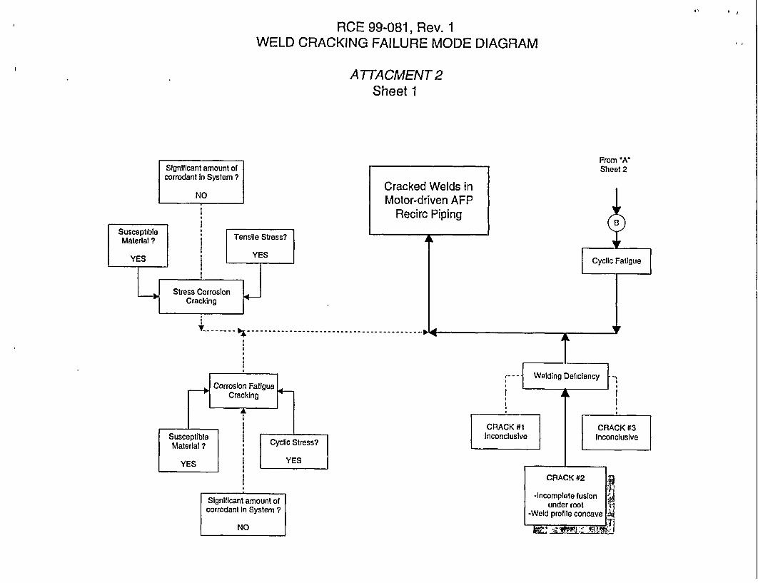
events. A Failure Mode Diagram (Attachment 2) was then developed to examine the contributions from
various identified failure modes and determine the predominant mode. A Cause & Effect technique was
used to construct the failure scenario and identification of the root and contributing cause.
Failure Mode Identification
Transgranular Stress Corrosion Cracking (TGSCC)
TGSCC is not considered to be the predominant failure mode for the following reasons:
"* This failure mechanism depends on the co-existence of a susceptible material, tensile stress, and an
aggressive environment containing a corrodant. Although the material and the stresses (from vibration
to be discussed later) are present, the positive presence of a corrodant such as chlorine cannot be
established. Plant procedures to control and monitor secondary chemistry assure that the chloride level
is maintained <2 ppb.
"* Residual chlorine typical of stainless steel component manufacturing was adequately addressed during
implementation of modification MR 88-099 by the addition of procedural notes in the associated IWPs
to flush new components with demineralized water before installation.
* Since the SCC mechanism is promoted by system chemistry, failures would be expected to be more
widespread. Multiple points of crack initiation (at the same joint) and multiple locations (throughout
interconnected systems) would be expected. Although there have been three recent crack occurrences,
their location within a specific section of piping, known to be subjected to abnormal vibration, suggests
a different failure mechanism.
* Because SCC is not particularly stress-related, the recurrence within the high-vibration AF Pump
recirc. lines suggests a different failure mechanism.
9

RCE 99-081, Rev. ISocket-Weld Failures in AF Pump Recirc. Piping
Corrosion Fatigue Cralking
Corrosion Fatigue Cracking is not considered to be the predominant failure mode, for the same reasoning
given in the above discussion. The primary difference between Corrosion Fatigue Cracking and Stress
Corrosion Cracking is in the application of stress, the former characterized by cyclic loading, and in the
later by a static tensile stress. As in the above discussion, positive evidence of the existence of a corrodant
has not been concluded and therefore this mechanism is also unsupported.
Weldine Deficiency
A welding deficiency is not considered to be the predominant failure mode. Only one of the three cracked
welds (Crack #2) was able to be removed from the system without separation of the weld root. All three
welds appropriately received only VT (visual examination) during installation. It was apparent from the
failure analysis of Crack #2 that the crack was initiated at a location of likely stress concentration created by
a void under the weld root. Cyclic loading was determined to be the initiating mechanism. The void was
also observed at a non-crack location along the length of the weld. Slight concavity at the surface of the
weld in combination with the root void represented a reduction in the shear strength of the weld, providing
the path of crack propagation.
Cyclic Fatigue
Cyclic fatigue was determined to be the predominant failure mode responsible for the socket-weld failures.
The reasons for this conclusion are as follows:
"* The Technimet Report on Crack #2 concluded that crack initiation was by cyclic stresses at a stress
concentration created by the weld configuration.
"* Structural Integrity Associates review of Technimet's analysis concludes that the fracture
morphology observed in both CRACK 1 & 2 are representative of high cycle fatigue cracking.
* Abnormal high vibration of the recirc. piping is readily obvious by hand-touch.
* Structural Integrity Associates has verified from vibration data that stresses from low frequency
displacement are sufficient to fail welds of poor to fair quality.
* The direct cause of the excessive vibration is attributed to evidence of flow cavitation within
orifice device RO-4008. A boroscope examination of the orifice internals revealed significant
pitting damage. Since comparable vibration and noise are typical of the recirc. piping of all four
AF Pumps, it is reasonable to assume that cavitation is also occurring in the orifices not inspected.
Failure Mode Summary
Based on metallurgical failure analyses and vibration analysis, apparent contributions to the three cases of
weld cracking have been identified from the following failure modes:
* Transgranular Stress Corrosion Cracking
10

Socket-Weld Failures in AF Pump Recirc. Piping
"* Corrosion Fatigue Cracking
"* Welding Deficiency
"* Cyclic Fatigue
IV. Root Causes & Contributing Factors
Root Cause
The root cause of socket-weld failures in the AF Pump recirculation piping has been determined to be a
design deficiency because the restricting orifice design breakdown pressure was incorrectly specified. The
breakdown pressure rating, which dictates the number of internal breakdown stages, was specified in PO
#184514 for restricting orifices RO-4008 and RO-4015 as 2190 feet @ 70 gpm and 100*F (2190 ft = 948
psi). The orifices obtained are constructed with only two breakdown stages. The two-stage devices that
were provided and installed are insufficient to avoid high turbulence and cavitation under actual conditions.
Typical AF Pump discharge pressure is approximately 1250 psig. A reduction to at least 50 psig is
necessary to avoid lifting downstream relief valve AF-4035. Therefore, a differential pressure breakdown
of at least 1200 psi (-- 2771 feet) should have been specified. The pipe vibration resulting from installation
of the undersized orifices, has imposed cyclic fatigue stresses on vulnerable socket-welds.
Contributine Factors
"* In at least one of the three cases of cracked welds, it is concluded that the quality of the weld
contributed to the initiation of the failure. The presence of a sub-root void served to create a stress
concentration. Noted slight concavity of the weld surface contributed to crack propagation.
Identification of this deficient weld has not led to the suggestion that a programatic issue is involved.
"* The QA boundary in the recirc. piping modification was re-scoped for an unapparent reason. The
QA boundary was moved from the second isolation valve in the recirc. line, which included the
restricting orifice, to the first isolation valve, which excluded the orifice.
"* The re-scoping of the QA boundary apparently contributed to omission of any discussion concerning
the restricting orifice in the 1OCFR50.59 evaluation for the modification.
V. Corrective Actions
Actions Complete
"* An AF System water sample was obtained and analyzed for chlorine concentration, the results
indicating chlorine content to be < 5 ppb.
"* The U-bolt on support DB3A-1003G was tightened to allow recirc. piping vibration data to be
compared before and after the tightening. (WO Tag #152252)
11
RCE 99-081, Rev. I

Socket-Weld Failures in AF Pump Recirc. Piping
Short Term Corrective Actions
"* CA #1 Responsible Group: Maintenance, Completion Due Date: 8/1/99
Evaluate the throat profile of socket-ývelds in the AF Pump recirculation lines, from the tie-in to the
pump discharge pipe to the first manual isolation valve. WO's 9909185, 9909186, 9909187, and
9909188 have been submitted to perform this activity. Welds determined to be unacceptable should be
replaced with an oversized 2/1 configuration as described in EPRI PR 107455 and 111188.
" CA #2,. Responsible Group: NMS, Completion Due Date: 8/15/99
Obtain vibration data from the vertical portion of the P-38A recirc. piping for comparison to the data
obtained prior to the tightening of the U-bolt on support DB3A-1003G.
Long Term Corrective Actions
* CA #1, Responsible Group: SDM. Completion Due Date: 4f quarter 2000
In coordination with EWR 99-031, evaluate a resolution and process an appropriate design
modification request to provide adequate pressure reduction in the AF recirculation lines.
The resulting modification should include replacement of recirc. line welds from the 90' elbow
upstream of the restricting orifice to the upstream weld on the recirc. line manual isolation valve. The
socket welds should be oversized in a 2/1 configuration as described in EPRI PR 107455 and 111188.
The modification should identify vibration acceptance criteria for the design. If the criteria cannot be
met, vibration data should be obtained/analyzed so that the piping can be re-supported to reduce the
vibration.
The modification should ensure that appropriate design documentation of the replacement pressure
reducing method or device is obtained and incorporated into controlled station documents.
Modifications MR 99-029*A(*B)(*CX*D) have been assigned for this action.
.CA #2, Responsible Group: SEP, Completion Due Date: 2 d quarter 2000
Conduct Engineering Training on the modification aspects of this Root Cause Evaluation, particularly
the design deficiency related to the inadequate specification of the orifice differential breakdown
pressure.
12
RCE 99-081, Rev. I

Socket-Weld Failures in AF Pump Recirc. Piping
VI. References
1. MR 88-099*A, B, C, D, Increased Aux. Feedwater Pump Mini-Recirc Line Capacity
2. CR 99-1391, SCAQ on Potential Common Mode Failure Mechanism
3. CR 99-1368, P-38B crack at AF-40, discovered 5/19/99 (Crack #3)
4. CR 99-1163, P-38A crack at elbow, discovered 4/24/99 (Crack #2)
5. CR 98-2589, R0-4008 Pressure Reducing Orifice Damage
6. CR 98-2550, P-38A crack atAF-27, discovered 6/27/98 (Crack #1)
7. CR 97-0720, Control Room Background Noise Level
8. EWR 99-031, AF Pump Recirc Noise in Control Room
9. Technimet Report No. 100353, Failure Analysis of a Pipe Section, 816198
10. Technimet Report No. 101609, Failure Analysis of a Pipe Section Weld, 6/2/99
11. Letter from Larry Dorfman, Structural Integrity Associates, Inc., to John P. Schroeder,WE, 6/10/99
12. P&ID M-217 Sheet 1, Auxiliary Feedwater System
13. Bechtel Isometric Drawing P-103
14. Bechtel Isometric Drawing P-159
15. Primary ISI Isometric Drawing ISI-PRI-1352
16. Primary ISI Isometric Drawing ISI-PRI-1353
17. Primary ISI Isometric Drawing ISI-PRI-1354
18. Primary ISI Isometric Drawing ISI-PRI-2338
19. Drawing SK-AFW-008/88-099, Working Isometric for P-38A Recirc Line to CST
20. Drawing SK-AFNV-009/88-099, Working Isometric for P-38B Recirc Line to CST
21. PBNP FSAR Section 10.2, Auxiliary Feedwater System
22. Design Basis Document DBD-01, Auxiliary Feedwater System
23. NRC Bulletin 88-04, Potential Safety-Related Pump Loss
24. NRC Generic Letter 89-04
25. Q-List Discrepancy 96-058
26. Calculation N-91-063, P38A & B Recirc. Line System Characteristics
27. Calculation N-91-069, Impact of Higher Capacity Recirc. System for the ... Motor Driven AFW Pumps
28. Structural Integrity Associates, Inc. Report No. SIR-99-136, November 1999, Failure Assessment of
the WEPCO - PBNP s Auxiliary Feedwater Recirculation Line Socket Weld Fatigue Failure
29. MR 99-029*A(*B)(*C)(*D), Aux. Feedwater Pumps Minimum Flow Recirc Line Orifice
VII. Attachments
Attachment 1: Event & Causal Factors Chart, Sheets 1 and 2
Attachment 2: Failure Mode Diagram, Sheets 1 and 2
13
RCE 99-081, Rev. I

e~rilgn and basis f or\. ( orifice breakdown '•
pressure rating / "..... unknown
RCE 99-081, Rev.1 WELD CRACKING IN AF PUMP RECIRC. PIPING
EVENTS & CAUSAL FACTORS CHART
ATTACHMENT 1 Sheet I
utilizes questionable value of orifice DP
6/24/91
Decision made to reduce QA Scope of
MOD 88-099*A°B*C*D
"Technical Justification for QA scope change
not provided
Revised per 7/20/99 CARB
4/4/94
AF System DBD01 Issued
describing safetyrelated functions
of the orifices

RCE 99-081, Rev. 1 WELD CRACKING IN AF PUMP RECIRC. PIPING
EVENTS & CAUSAL FACTORS CHART
A TTACHMENT 1 Sheet 2
Noise distraction In Control Rm
reported (CR 97-0720)
Request for evaluationresolution of recirc vibes,
cavitation, & noise (EWR 99-031)
5/24/99
CR 99-1391
314197 12/8/98
1, 1 1 •
RCE 99-081, Rev. 1 WELD CRACKING FAILURE MODE DIAGRAM
ATTACMENT 2 Sheet 1
CRA Incon
From "A" Sheet 2
"--- Welding eficlency -]
CK #1 CRACK #3 cluslve Inconclusive
Cracked Welds in Motor-driven AFP
Recirc Piping

RCE 99-081, Rev. 1 WELD CRACKING FAILURE MODE DIAGRAM
ATTACMENT2 Sheet 2
Specified breakdown pressure of 2190 ft
insufficient for actual conditions
------------J
Origin of 2190 ft , unknown, but utilized
iIn Cat N-91-063 (6/24/91)
Technical Justification for QA scope reduction cannot be determined
To 1B" Sheet 1
4