point-cloud multi-contact planning for humanoids
TRANSCRIPT
HAL Id: lirmm-00863931https://hal-lirmm.ccsd.cnrs.fr/lirmm-00863931
Submitted on 19 Sep 2013
HAL is a multi-disciplinary open accessarchive for the deposit and dissemination of sci-entific research documents, whether they are pub-lished or not. The documents may come fromteaching and research institutions in France orabroad, or from public or private research centers.
L’archive ouverte pluridisciplinaire HAL, estdestinée au dépôt et à la diffusion de documentsscientifiques de niveau recherche, publiés ou non,émanant des établissements d’enseignement et derecherche français ou étrangers, des laboratoirespublics ou privés.
Point-Cloud Multi-Contact Planning for Humanoids:Preliminary Results
Stanislas Brossette, Joris Vaillant, François Keith, Adrien Escande,Abderrahmane Kheddar
To cite this version:Stanislas Brossette, Joris Vaillant, François Keith, Adrien Escande, Abderrahmane Kheddar. Point-Cloud Multi-Contact Planning for Humanoids: Preliminary Results. RAM: Robotics, Automationand Mechatronics, Nov 2013, Manila, Philippines. pp.19-24, �10.1109/RAM.2013.6758553�. �lirmm-00863931�
Point-Cloud Multi-Contact Planning for Humanoids:
Preliminary Results
Stanislas Brossette, Joris Vaillant, Francois Keith, Adrien Escande and Abderrahmane Kheddar
Abstract— We present preliminary results in porting ourmulti-contact non-gaited motion planning framework to operatein real environments where the surroundings are acquired usingan embedded camera together with a depth map sensor. Weconsider the robot to have no a priori knowledge of the environ-ment, and propose a scheme to extract the information relevantfor planning from an acquired point cloud. This yield thebasis of an egocentric on-the-fly multi-contact planner. We thendemonstrate its capacity with two simulation scenarios involvingan HRP-2 robot in various environment before discussing someissues to be addressed in our quest to achieve a close loopbetween planning and execution in an environment exploredthrough embedded sensors.
I. INTRODUCTION
Humanoid robots are expected to move and achieve tasks
in ways similar to humans. In cumbersome and unstructured
environments, we humans move in a non-gaited acyclic way:
we choose appropriate parts of our body to create contacts
with the surrounding environment in order to support the
motion of the remaining parts while avoiding obstacles. A
whole motion is a sequence of contact creations and releases.
Since we are biped, we mostly use our feet to move. As
the environment becomes more difficult to cross, hands may
come into play together with feet to help with the motion.
Narrow passages may even require other parts of our body
(knees, elbows, back...) to make contact in order to support
the motion.
Recently, we have dedicated considerable efforts in
proposing a general multi-contact motion planner to solve
such cases of non-gaited acyclic planning. Given a humanoid
robot, an environment, a start and a final desired postures,
our planner generates a sequence of contact stances allowing
any part of the humanoid to make contact with any part of the
environment to achieve motion towards the goal. A typical
experiment with a HRP-2 robot achieving such an acyclic
motion is presented in [1], and the planner is thoroughly
described in [2]. Extensions of this multi-contact planner to
multi-agent robots and objects gathering locomotion and ma-
nipulation are presented in [3], and preliminary validations
with some DARPA challenge scenarios, such as climbing
a ladder, ingress/egress a utility car or crossing through a
relatively constrained pathway are presented in [4]. In [2]
and [3], we describe works in multi-contact that are achieved
by other colleagues in robotics.
CNRS-UM2 LIRMM Interactive Digital Humans, UMR0056, Montpel-lier, France
CNRS-AIST Joint Robotics Laboratory (JRL), UMI3218/CRT, Tsukuba,Japan
This work is supported in part by the FP7 IP RoboHow.Cog project
All of our previous works, namely the planning scenarios
experimented on the HRP-2 humanoid robot, use perfect
3D models of the environment to plan motion. In fact,
our previous experiments use model-based, off-line, multi-
contact planning. The results are then experimented on
the real environment only after a very careful calibration
assuming no changes in the object’s positions occur during
the trials. To achieve dynamic motions that account for whole
body motion, we still use off-line planning, see e.g. in [5].
Practical implementation and use of our multi-contact
planner will not be a plausible option if it cannot be extended
to work with data acquired directly from the robot’s em-
bedded sensors. Namely, if the environments and composing
object models are known, then the robot-environment careful
calibration would be ideally done by the robot continuously.
In contrast, if the environments and/or composing object
models are not known, then the robot must acquire them
progressively and build knowledge on which multi-contact
planning can still be carried out. This paper examines the
possibility to extend our multi-contact planner to work with
information acquired by the humanoid embedded visual
system, a camera with depth information, providing 3D point
cloud data. We assume that we do not have the 3D models
of the environment and composing objects.
Although preliminary, our first trials show promising re-
sults. We describe the changes made on our multi-contact
planner to work with partial 3D point maps, and present two
case studies of successful multi-contact planning simulations
on 3D point clouds with the HRP-2 humanoid robot. As a
preliminary work, we dedicate a large part of our contribution
for discussion.
II. BACKGROUND AND MOTIVATION
Our multi-contact planning (MCP) is made of several
modules. The Fig. 1 illustrates the main components and their
relation. The core of the planner consists in the multi-contact
search and the posture generator. The former incrementally
builds a tree of contact sets. The children of a node are
obtained by adding or removing exactly one contact to its
set. At each iteration of the search, the best leaf, according
to a potential field, is expanded this way. The tentative
sets of contacts are tested by the posture generator: for a
given set of contacts, it attempts to find a configuration of
the robot that satisfies these contacts while being statically
stable, avoiding collision and staying within the robot’s state
and torques limits. This is done by automatically writing and
solving a non-linear optimization problem. Upon success, the
contact set is validated, and a new leaf is created. The goal is

Fig. 1. Multi-contact planner architecture.
written as a set of constraints defining a sub-manifold of the
configuration space. A node is the final node if its associated
posture generation problem augmented by these constraints
remains feasible. By backtracking from this final node to the
initial root node, we obtain a sequence of nodes and thus a
sequence of contact sets, that can be executed on the robot
by a whole-body controller. We developed such a controller
based on a quadratic programming (QP) formulation [6].
The potential field is derived from a crude path, made of
a few key postures, that does not take contacts into account.
Such a path is either user-defined or can be the output of a
first dedicated planner [7].
The MCP relies largely on the 3D geometric models of the
environment and robotic agents. In our previous work [2],
[3], the geometric models are provided by the user. The
contact transition for the robot are planned off-line and later
executed by the robot assuming exactness of the models
and their relative positioning. We aim at extending our
MCP to deal directly with real data acquired by the robot.
Subsequently, we must deal with two kinds of situations:
1) the models of the objects in the environment are
known: in this case adapting the MCP consists mainly
in dealing with recognition, model superposition and
handling uncertainties. In brief, once model superpo-
sition is achieved, we can use the 3D model for MCP
as in [2], [3], yet some adjustments are needed.
2) the models of the hurdles and the environment are
not known (e.g. disaster or outdoor environments, for
example related to the Fukushima disaster that inspired
the DARPA Robotic Challenge), MCP is to be achieved
in an ego-centric way with models built from the
robot’s embedded sensors. This paper deals with this
case and we describe how the MCP is modified to
achieve this goal. In a nutshell, we construct planar
surfaces from the 3D point clouds data and feed them
to the MCP.
In robotics, the use of 3D-based vision for recognition and
navigation in environment known or partially unknown has
first been used on mobile robots, evolving in flat environ-
ment, for example by coupling it with a SLAM system [8].
Another approach consists in extracting the surfaces from the
point cloud, and then link them to the known environment
or simply consider them as obstacles to be avoided [9].
Since working on raw point clouds is costly because of the
high number of data points, this extraction has also been
enhanced [10] in order to be run in real-time. This approach
has been recently experimented on a humanoid robot in [11],
that combines two methods: the surface extraction from a
point cloud, and the voxel-based 3D decomposition of the
environment [12]. Still, since the robot only navigates in a
flat environment, and does not realize manipulation tasks,
the surfaces extracted from the 3D point cloud are down
projected to a 2D plan, on which are based the navigation
and collision avoidance processes.
The use of humanoid robots allows to navigate in more
complex environment, and recently, some work has been
done to make a humanoid robot go down a ramp [13] or
climb stairs [14]. Yet, those methods use laser-based vision
rather than point-cloud-based vision, so as to have a precise
analysis of a known environment.
In this work, we aim at enabling a robot to analyze and
plan a motion into a 3D environment. Hence, we use the
surface extraction of a point cloud to directly have a global
picture of the environment and determine the convex planar
surfaces that the robot can use at its advantage to progress
using the MCP. In our approach to make such an extension,
we intentionally seek for technical solutions that minimize
changes to be done on our existing MCP software.
III. BUILDING AN UNDERSTANDABLE ENVIRONMENT
FOR OUR PLANNER
Our first concern is to build an environment that our
multi-contact planner is able to “understand” and that can
be extracted from a point cloud scene.
The simplest entity that our planner would be able to
deal with and that could correctly describe the robot’s
environment is a set of convex polygonal planar surfaces.
Therefore, starting from an acquired point cloud, we try to
extract a relevant set of such geometrical entities that will
be a first description of the surroundings of the robot.
In this section, we present the different steps we follow to
create a set of relevant convex polygonal plane surfaces out
of an acquired point cloud.
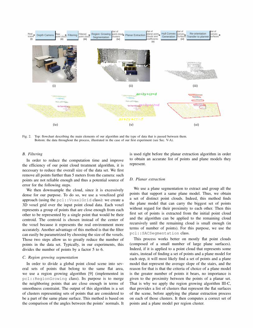
The Fig. 2 illustrates the major steps of this point cloud
treatment. We use Willow Garage’s Point Cloud Library1
(PCL) [15] extensively for processing the point cloud.
A. Acquisition of point cloud from a RGB and depth sensor
For our experiments, we use an Asus Xtion Pro camera,
that provides a 640×480 pixel depth image, and the OpenNI
Grabber. The obtained point cloud representing our scene
contains points defined by their space coordinates and colors,
and will be the entry of our point cloud treatment algorithm.
We do not use the color information for now except for
display purpose. It may however be useful in the future
in matching object models with sensor data and to perform
color-based region growing algorithms.
1http://pointclouds.org/
ax+by+cz=d
ax+by+cz=d
ax+by+cz=d
(i) (ii)
(iv) (v)
(iii)
(vi)
Depth Camera Region GrowingSegmentation
Planar ExtractionFiltering Hull ConvexGeneration
Re-orientationTransfer to planner
Rawpoint cloud
(ii)
Filteredpoint cloud
(iii)
Set ofpoint cloudclusters
(iv)
Set ofplanar pointclouds andcoefficients
(v)
Realscene
(i)
Set ofconvexSurfaces
(vi)
Set ofconvexsurfaces
Fig. 2. Top: flowchart describing the main elements of our algorithm and the type of data that is passed between them.Bottom: the data throughout the process, illustrated in the case of our first experiment (see Sec. V-A).
B. Filtering
In order to reduce the computation time and improve
the efficiency of our point cloud treatment algorithm, it is
necessary to reduce the overall size of the data set. We first
remove all points further than 5 meters from the camera: such
points are not reliable enough and thus a potential source of
error for the following steps.
We then downsample the cloud, since it is excessively
dense for our purpose. To do so, we use a voxelized grid
approach (using the pcl::VoxelGrid class): we create a
3D voxel grid over the input point cloud data. Each voxel
represents a group of points that are close enough from each
other to be represented by a single point that would be their
centroid. The centroid is chosen instead of the center of
the voxel because it represents the real environment more
accurately. Another advantage of this method is that the filter
can easily be parametrized by choosing the size of the voxels.
Those two steps allow us to greatly reduce the number of
points in the data set. Typically, in our experiments, this
divides the number of points by a factor 5 to 6.
C. Region growing segmentation
In order to divide a global point cloud scene into sev-
eral sets of points that belong to the same flat area,
we use a region growing algorithm [9] (implemented in
pcl::RegionGrowing class). Its purpose is to merge
the neighboring points that are close enough in terms of
smoothness constraint. The output of this algorithm is a set
of clusters representing sets of points that are considered to
be a part of the same plane surface. This method is based on
the comparison of the angles between the points’ normals. It
is used right before the planar extraction algorithm in order
to obtain an accurate list of points and plane models they
represent.
D. Planar extraction
We use a plane segmentation to extract and group all the
points that support a same plane model. Thus, we obtain
a set of distinct point clouds. Indeed, this method finds
the plane model that can carry the biggest set of points
without regard for their proximity to each other. Then this
first set of points is extracted from the initial point cloud
and the algorithm can be applied to the remaining cloud
recursively until the remaining cloud is small enough (in
terms of number of points). For this purpose, we use the
pcl::SACSegmentation class.
This process works better on mostly flat point clouds
(composed of a small number of large plane surfaces).
Indeed, if it is applied to a point cloud that represents some
stairs, instead of finding a set of points and a plane model for
each step, it will most likely find a set of points and a plane
model that represent the average slope of the stairs, and the
reason for that is that the criteria of choice of a plane model
is the greater number of points it bears, no importance is
given to the proximity between the points of a planar set.
That is why we apply the region growing algorithm III-C,
that provides a list of clusters that represent the flat surfaces
of the scene, before applying the planar extraction process
on each of those clusters. It then computes a correct set of
points and a plane model per region cluster.
E. Planar projection and hull convex generation
The exact knowledge of all the data points contained in the
plane model of a flat area is not necessary for our planning;
we can reduce the point cloud to its convex hull without
loss of information (except if the surface is concave, but this
issue will be tackled in future works). In order to obtain the
convex hull of each set of points, we first project every point
of the set on its plane model (pcl::ProjectInliers
class) and then compute the 2D convex hull of the projected
set of points (pcl::ConvexHull class). After this step,
each plane surface of the scene is represented by a frame
composed of 3 vectors that are respectively a tangent, bi-
tangent and normal vector of the plane model, an origin point
that is the barycentre of the set of points and a small set of
points that define its convex hull (the points’ coordinates
being calculated in the referential defined by the frame and
the origin of the surface in order to make further calculations
easier).
F. Re-orientation and transfer to the planner
Before sending the previously computed data to the plan-
ner, it is necessary to take into account the initial orientation
of the camera. Indeed, if the camera was not aiming in a
perfectly horizontal direction, then the entire point cloud
would be misoriented. Therefore, it is necessary to re-
orientate the surfaces before sending them to the planner. To
do so, we simply apply a rotation matrix (that is computed
from the initial camera orientation) to each of our data set’s
frame and origin to settle that problem. From there, the
transfer of the surfaces to the planner can be done without
any specific issue.
Re-orientation is done as a last step for the sake of
performance: obviously we need to re-orient only a few
frames, compared to an early re-orientation of the point cloud
that would require to apply a transformation on thousands of
points.
IV. PLANNING ON POINT CLOUDS
A. Convex surfaces inclusions
We adjusted slightly our planner and posture generator to
handle contacts between convex polygonal plane surfaces.
The main modification made in the posture generator deals
with properly writing the constraints that enforce the in-
clusion of one surface into another one. In our previous
implementation, contacts are searched between rectangular
patches attached to the robot body or the environment.
Now any polygonal convex-shaped patch can be checked
for inclusion in another; that is to say, the vertices of a
convex 2D polygon are indexed counter-clockwise around
its carrying plane surface’s normal vector. A point that is
inside the polygon is on the left side of all its edges. On
the opposite, a point that is outside of the polygon will be
on the right side of at least one of the polygon’s edges.
The following is the algorithm we use for the constraint
generation:
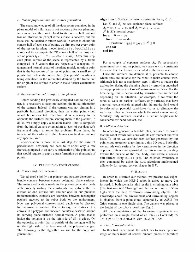
Algorithm 1 Surface inclusion constraints for Si ⊂ Sj
Let Si and Sj be two coplanar plane surfaces
Si = p0, p1, . . . , pn and Sj = q0, q1, . . . , qm~N is Si’s normal vector
for k = 0 → n do
for l = 0 → m do
Constraint : [−−→qlpk ×−−−→qlql+1] . ~N ≤ 0end for
end for
For a couple of coplanar surfaces Si, Sj respectively
represented by n and m points, we create n×m constraints
to ensure that the former is included in the latter one.
Once the surfaces are defined, it is possible to choose
which ones are suitable for the robot to make contact with.
Although it is not a mandatory step, it allows to reduce the
exploration during the planning phase by removing undesired
or inappropriate pairs of robot/environment surfaces. For the
time being, this is determined by heuristics that are defined
depending on the situation. For example, if we want the
robot to walk on various surfaces, only surfaces that have
a normal vector closely aligned with the gravity field would
be selected as potential candidates (so as to eliminate the
walls and other surfaces on which the robot cannot walk).
Similarly, only surfaces located at a certain height can be
considered for hand contact, etc.
B. Collision detection
In order to generate a feasible plan, we need to ensure
that the robot avoids collisions with its environment and with
itself. To do so, we consider each surface generated by our
point cloud treatment algorithm as a thin 3D body. Basically,
we extrude each surface by few centimetres in the direction
opposite to its normal (provided that this normal is pointing
toward the outside of the real body) and create a convex
hull surface using QHull [16]. The collision avoidance is
then computed by using the GJK algorithm implemented
efficiently for several convex shapes in [17].
V. RESULTS
In order to illustrate our method, we present two exper-
iments in which the HRP-2 robot is asked to move 2m
forward. In both scenarios, this results in climbing on a table
(The first one is 0.71m-high and the second one is 0.53m-
high) with the help of various surrounding objects. The
knowledge about the environment and surrounding objects
is obtained from a point cloud captured by an ASUS Pro
Xtion camera in one single shot. The camera was placed at
the height of the robot’s head, see Fig. 2.
All the computations of the following experiments are
performed on a single thread of an Intel(R) Core(TM) i7-
3840QM CPU at 2.80GHz, with 16Go of RAM.
A. Plan 1: irregular stairs
In this first experiment, the robot has to walk up some
irregular stairs made of several random pieces of furniture
to reach its goal. The filtered point cloud contained 60286
points, that were split into 6 plane surfaces. The whole cloud
processing was done in 2.7 s. The planner computations
generates a path of 11 nodes, some of which are depicted
in Fig. 3. We notice that the robot climbs the stairs one
by one without ever putting its two feet on the same step
and without any noticeable problem. In total, 23 nodes were
generated and the planning time was 98.4 s.
B. Plan 2: helping motion with the hand
This second experiment was designed to showcase a more
complex plan involving the use of the HRP-2 upper limbs.
In this experiment, the filtered point cloud contained 66907
points, from which 11 surfaces were extracted. The whole
cloud processing was done in 2.7 s. The planner computation
generates a path of 19 nodes, some of which are depicted
in Fig. 4. To climb on the table, the robot uses its left arm
and walks on an inclined slope before climbing a step at the
end of the slope, once again, with the help of its left arm as
support. In total, 40 nodes were generated and the planning
time was 122.3 s.
VI. DISCUSSION
This work is a first step toward a fully sensory-perception-
based multi-contact planner. It raises several interesting ques-
tions on the way to adapt our MCP.
One advantage of our approach is to avoid having to
precisely position the robot in the environment prior to the
plan execution. Yet, for now the positioning is done once
and for all with the acquisition of the point cloud, before
planning. When executing the plan, the robot might still
deviate from it, for example a support might move, or a
foot might contact a few centimetres away from where it
was planned to, or the support might not be at its expected
position because of measurement errors in the acquired point
cloud. We thus need to close the loop between the planning
and its execution. To do so, we need robust detection of
discrepancies to be made by the robot. This can be achieved
by combining point-cloud-based SLAM with contact sens-
ing. Once the robot has acquired knowledge of its deviation
or of the position error of the support, it has to adapt to it.
This adaptation should not be time-consuming so as to not
interrupt the execution for too long. A slight deviation can be
recovered by simply positioning with care the next contacts
and the closed-loop multi-contact controller shall work on
guarded-motions basis. However, a bigger deviation might
make the next contact stances infeasible. In this later case,
re-planning the next contacts is necessary to go back to the
plan. How many contacts have to be re-planned depends on
the context. In difficult situations, changes in contacts might
cascade up to requiring an entire re-planning. Recognizing
the situation should be the task of a local planner that re-
plans as few steps as possible. In case too much contacts
must be reprocessed, the re-planning phase can be stopped
before it ends and resumed at the next step.
This partial planning approach can also be seen in the
context of semi-autonomous motion: an operator gives the
overall direction with, for example, a joystick, and the
planner reactively finds a sequence of a few contact sets
to move as closely as possible in this desired direction. The
operator is thus in charge of preventing the robot from getting
stuck while the planner only concentrates on finding the
correct contacts over a short time window.
Another question stems from the partial knowledge of the
environment: it is not possible to give a guide path as we used
to do with the 3D models. This guide path will necessarily
be very crude, either a line to a desired position, or a plan
in a known environment before it was changed (for example
in the case of a disaster in a plant). The planning must then
be driven also by the need of getting information about the
environment, for example reaching a viewpoint allowing to
see parts of the environment that were hidden before, filling
empty spaces and possibly adding new supports on-the-fly.
Planning is then only partial since necessary part of the
environment might be unknown.
Later on, the discovery of the environment might be
improved by the use of other sensors. One can then imagine
having the robot test for a contact to ensure a given surface is
fit for support or that it is precisely at the position measured
by vision. If the surface is not, this is another kind of
discrepancy in the plan than needs to be handled by re-
planning.
VII. CONCLUSION
We present preliminary results in extending our previous
work in multi-contact planning to operate directly on en-
vironment that is built on-the-fly from a robot’s embedded
sensors. This first study makes use of depth camera and
implemented modules from the PCL which extract planar
surfaces that are fed to our MCP. We intentionally seek
for technical implementations that minimize the changes on
our existing MCP software and illustrate successful plans
generated on the basis of 3D point clouds solely.
The simulation results revealed that indeed our MCP does
not require major adjustments to handle egocentric sensory
data. Of course, this does not mean that we are fully satisfied
since our results also suggest additional future work.
First, although we choose to treat the case of not having
3D models, we believe that the implementation of an MCP
with knowledge of the 3D model is necessary. For example,
even in a disaster situations as in Fukushima nuclear power
plants, the inside exploration videos available show that
many objects kept their shape and were not totally destroyed
(e.g. door, stairs, ladders, etc.). So having their model would
then still permit our MCP to rely on 3D models to plan
contacts for motion. PCL provides only partial information,
it is then necessary to drive the planner by the mission
objective and also a perceptual one (e.g. SLAM). Of course,
our ultimate future plan is to handle uncertainties, control
and planning recovery of discrepancies when they occur.
ACKNOWLEDGEMENT
The first author thanks Thomas Moulard for his help and
support with the RobOptim software, as well as Benjamin
Chretien for his advices.

Fig. 3. Table climbing simulation using irregular stairs. Of the 11 nodes of the path, we depicted the nodes 1, 4, 6, 8, 10 and 11.
Fig. 4. Slope and step climbing simulation. Of the 19 nodes of the path, we depicted the nodes 1, 7, 12, 15, 17 and 18.
REFERENCES
[1] A. Escande, A. Kheddar, S. Miossec, and S. Garsault, “Planningsupport contact-points for acyclic motions and experiments on HRP-2,” in International Symposium on Experimental Robotics, Athens,Greece, 14-17 July 2008.
[2] A. Escande, A. Kheddar, and S. Miossec, “Planning contact points forhumanoid robots,” Robotics and Autonomous Systems, vol. 61, no. 5,pp. 428 – 442, 2013.
[3] K. Bouyarmane and A. Kheddar, “Humanoid robot locomotion andmanipulation step planning,” Advanced Robotics, vol. 26, 2012.
[4] K. Bouyarmane, J. Vaillant, F. Keith, and A. Kheddar, “Exploring hu-manoid robot locomotion capabilities in virtual disaster response sce-narios,” in IEEE/RSJ International Conference on Humanoid Robots,Osaka, Japan, December 2012, pp. 337–342.
[5] S. Lengagne, J. Vaillant, E. Yoshida, and A. Kheddar, “Generationof whole-body optimal dynamic multi-contact motions,” International
Journal of Robotics Research, vol. (to appear), 2013.[6] K. Bouyarmane and A. Kheddar, “Using a multi-objective controller
to synthesize simulated humanoid robot motion with changing contactconfigurations,” in IEEE/RSJ International Conference on Intelligent
Robots and Systems, San Fransico, CA, 25-30 September 2011.[7] K. Bouyarmane, A. Escande, F. Lamiraux, and A. Kheddar, “Collision-
free contacts guide planning prior to non-gaited motion planning forhumanoid robots,” in IEEE International Conference on Robotics and
Automation, 2009.[8] M. Whitty, S. Cossell, K. Dang, J. Guivant, and J. Katupitiya, “Au-
tonomous navigation using a real-time 3d point cloud,” in ACRA’10:
Australasian Conference on Robotics & Automation, Brisbane, 1 - 3December 2010.
[9] J. Poppinga, N. Vaskevicius, A. Birk, and K. Pathak, “Fast planedetection and polygonalization in noisy 3d range images,” in IEEE/RSJ
International Conference on Intelligent Robots and Systems (IROS),Sept 2008, pp. 3378–3383.
[10] J. Biswas and M. M. Veloso, “Depth camera based indoor mobilerobot localization and navigation,” in IEEE International Conference
on Robotics and Automation, 2012, pp. 1697–1702.
[11] D. Maier, A. Hornung, and M. Bennewitz, “Real-time navigation in3D environments based on depth camera data,” in Humanoids’12:
12th IEEE-RAS International Conference on Humanoid Robots,Osaka, Japan, November 2012.
[12] A. Nakhaei and F. Lamiraux, “Motion planning for humanoid robotsin environments modeled by vision,” in Humanoids’08: 8th IEEE-RAS
International Conference on Humanoid Robots, Dec 2008, pp. 197–204.
[13] C. Lutz, F. Atmanspacher, A. Hornung, and M. Bennewitz, “Naowalking down a ramp autonomously,” in IEEE/RSJ International
Conference on Intelligent Robots and Systems (IROS), Oct. 2012, pp.5169–5170.
[14] S. Oßwald, A. Hornung, and M. Bennewitz, “Improved proposalsfor highly accurate localization using range and vision data,” inIEEE/RSJ International Conference on Intelligent Robots and Systems
(IROS), Vilamoura, Portugal, October 2012, pp. 1809–1814.
[15] R. B. Rusu and S. Cousins, “3D is here: Point cloud library (pcl),” inIEEE International Conference on Robotics and Automation, Shang-hai, China, May 9-13 2011.
[16] H. H. C. Bradford Barber, David P. Dobkin, “The Quickhull algorithmfor convex hulls,” in ACM Transactions on Mathematical Software,
Vol. 22, University of Minnesota, December 1996, pp. 469–483.
[17] M. Benallegue, A. Escande, S. Miossec, and A. Kheddar, “FastC1 proximity queries using support mapping of sphere-torus-patchesbounding volumes,” in IEEE International Conference on Robotics
and Automation, 2009.