polar encoder/decoder v1 - xilinx.com polar encoder/decoder core provides: • polar decode for a...
TRANSCRIPT

Polar Encoder/Decoder v1.0
LogiCORE IP Product Guide
Vivado Design SuitePG280 June 6, 2018

Polar Encoder/Decoder v1.0 2PG280 June 6, 2018 www.xilinx.com
Table of ContentsIP Facts
Chapter 1: OverviewFeature Summary. . . . . . . . . . . . . . . . . . . . . . . . . . . . . . . . . . . . . . . . . . . . . . . . . . . . . . . . . . . . . . . . . . 5Applications . . . . . . . . . . . . . . . . . . . . . . . . . . . . . . . . . . . . . . . . . . . . . . . . . . . . . . . . . . . . . . . . . . . . . . 6Licensing and Ordering . . . . . . . . . . . . . . . . . . . . . . . . . . . . . . . . . . . . . . . . . . . . . . . . . . . . . . . . . . . . . 6
Chapter 2: Product SpecificationPort Descriptions . . . . . . . . . . . . . . . . . . . . . . . . . . . . . . . . . . . . . . . . . . . . . . . . . . . . . . . . . . . . . . . . . . 9Data Interfaces . . . . . . . . . . . . . . . . . . . . . . . . . . . . . . . . . . . . . . . . . . . . . . . . . . . . . . . . . . . . . . . . . . . 12Standards . . . . . . . . . . . . . . . . . . . . . . . . . . . . . . . . . . . . . . . . . . . . . . . . . . . . . . . . . . . . . . . . . . . . . . . 18Performance. . . . . . . . . . . . . . . . . . . . . . . . . . . . . . . . . . . . . . . . . . . . . . . . . . . . . . . . . . . . . . . . . . . . . 18Register Space . . . . . . . . . . . . . . . . . . . . . . . . . . . . . . . . . . . . . . . . . . . . . . . . . . . . . . . . . . . . . . . . . . . 25
Chapter 3: Designing with the CoreClocking. . . . . . . . . . . . . . . . . . . . . . . . . . . . . . . . . . . . . . . . . . . . . . . . . . . . . . . . . . . . . . . . . . . . . . . . . 36Resets . . . . . . . . . . . . . . . . . . . . . . . . . . . . . . . . . . . . . . . . . . . . . . . . . . . . . . . . . . . . . . . . . . . . . . . . . . 36Interrupt . . . . . . . . . . . . . . . . . . . . . . . . . . . . . . . . . . . . . . . . . . . . . . . . . . . . . . . . . . . . . . . . . . . . . . . . 36Interfaces . . . . . . . . . . . . . . . . . . . . . . . . . . . . . . . . . . . . . . . . . . . . . . . . . . . . . . . . . . . . . . . . . . . . . . . 37Polar Code Support . . . . . . . . . . . . . . . . . . . . . . . . . . . . . . . . . . . . . . . . . . . . . . . . . . . . . . . . . . . . . . . 37
Chapter 4: Design Flow StepsCustomizing and Generating the Core . . . . . . . . . . . . . . . . . . . . . . . . . . . . . . . . . . . . . . . . . . . . . . . . 41Constraining the Core . . . . . . . . . . . . . . . . . . . . . . . . . . . . . . . . . . . . . . . . . . . . . . . . . . . . . . . . . . . . . 43Simulation . . . . . . . . . . . . . . . . . . . . . . . . . . . . . . . . . . . . . . . . . . . . . . . . . . . . . . . . . . . . . . . . . . . . . . 43Synthesis and Implementation . . . . . . . . . . . . . . . . . . . . . . . . . . . . . . . . . . . . . . . . . . . . . . . . . . . . . . 44
Chapter 5: C ModelUnpacking and Model Contents . . . . . . . . . . . . . . . . . . . . . . . . . . . . . . . . . . . . . . . . . . . . . . . . . . . . . 45Installation . . . . . . . . . . . . . . . . . . . . . . . . . . . . . . . . . . . . . . . . . . . . . . . . . . . . . . . . . . . . . . . . . . . . . . 46C Model Interface. . . . . . . . . . . . . . . . . . . . . . . . . . . . . . . . . . . . . . . . . . . . . . . . . . . . . . . . . . . . . . . . . 47MATLAB Interface . . . . . . . . . . . . . . . . . . . . . . . . . . . . . . . . . . . . . . . . . . . . . . . . . . . . . . . . . . . . . . . . 52
Send Feedback

Polar Encoder/Decoder v1.0 3PG280 June 6, 2018 www.xilinx.com
Chapter 6: Example DesignSimulation-Only Example Design . . . . . . . . . . . . . . . . . . . . . . . . . . . . . . . . . . . . . . . . . . . . . . . . . . . . 54Processor-Based Example Design . . . . . . . . . . . . . . . . . . . . . . . . . . . . . . . . . . . . . . . . . . . . . . . . . . . . 55
Appendix A: Upgrading
Appendix B: DebuggingFinding Help on Xilinx.com . . . . . . . . . . . . . . . . . . . . . . . . . . . . . . . . . . . . . . . . . . . . . . . . . . . . . . . . . 58Debug Tools . . . . . . . . . . . . . . . . . . . . . . . . . . . . . . . . . . . . . . . . . . . . . . . . . . . . . . . . . . . . . . . . . . . . . 59Simulation Debug. . . . . . . . . . . . . . . . . . . . . . . . . . . . . . . . . . . . . . . . . . . . . . . . . . . . . . . . . . . . . . . . . 60Hardware Debug . . . . . . . . . . . . . . . . . . . . . . . . . . . . . . . . . . . . . . . . . . . . . . . . . . . . . . . . . . . . . . . . . 61Interface Debug . . . . . . . . . . . . . . . . . . . . . . . . . . . . . . . . . . . . . . . . . . . . . . . . . . . . . . . . . . . . . . . . . . 61
Appendix C: Polar Encoder/Decoder Bare-Metal DriverOverview . . . . . . . . . . . . . . . . . . . . . . . . . . . . . . . . . . . . . . . . . . . . . . . . . . . . . . . . . . . . . . . . . . . . . . . 63Data Structures . . . . . . . . . . . . . . . . . . . . . . . . . . . . . . . . . . . . . . . . . . . . . . . . . . . . . . . . . . . . . . . . . . 64User API . . . . . . . . . . . . . . . . . . . . . . . . . . . . . . . . . . . . . . . . . . . . . . . . . . . . . . . . . . . . . . . . . . . . . . . . 65Interrupt Handling . . . . . . . . . . . . . . . . . . . . . . . . . . . . . . . . . . . . . . . . . . . . . . . . . . . . . . . . . . . . . . . . 69Examples. . . . . . . . . . . . . . . . . . . . . . . . . . . . . . . . . . . . . . . . . . . . . . . . . . . . . . . . . . . . . . . . . . . . . . . . 69
Appendix D: Additional Resources and Legal NoticesXilinx Resources . . . . . . . . . . . . . . . . . . . . . . . . . . . . . . . . . . . . . . . . . . . . . . . . . . . . . . . . . . . . . . . . . . 71Documentation Navigator and Design Hubs . . . . . . . . . . . . . . . . . . . . . . . . . . . . . . . . . . . . . . . . . . . 71References . . . . . . . . . . . . . . . . . . . . . . . . . . . . . . . . . . . . . . . . . . . . . . . . . . . . . . . . . . . . . . . . . . . . . . 72Revision History . . . . . . . . . . . . . . . . . . . . . . . . . . . . . . . . . . . . . . . . . . . . . . . . . . . . . . . . . . . . . . . . . . 72Please Read: Important Legal Notices . . . . . . . . . . . . . . . . . . . . . . . . . . . . . . . . . . . . . . . . . . . . . . . . 73
Send Feedback

Polar Encoder/Decoder v1.0 4PG280 June 6, 2018 www.xilinx.com Product Specification
IntroductionThe Polar Encoder/Decoder soft IP core supports Polar encoding and decoding. The Polar codes are configurable and can be used on a block-by-block basis.
Note: In this document, a block is the general term for an atomic unit of data processed by an encoder or decoder. A codeword is the specific form of an encoded block and is used when discussing the code parameters used to generate it.
Features• Supports 3GPP TS 38.212 V15.1.1 3rd
Generation Partnership Project; Technical Specification Group Radio Access Network; NR; Multiplexing and channel coding (Release 15) [Ref 10]
• Polar encode or decode• Throughput(1) up to:
° >80 Mb/s for decoder (N=1024, K=200)
° >700 Mb/s for encoder (N=1024, K=200)• High bandwidth AXI4-Stream interfaces1. See Performance. Figures are for a clock frequency of
400 MHz and should be scaled for achieved clock frequency. Throughput is a function of many factors including code size, code mix, clock frequency and augmentation parameters.
IP Facts
LogiCORE™ IP Facts TableCore Specifics
Supported Device Family(1)
UltraScale™, UltraScale+™7 Series
Supported User Interfaces AXI4-Lite, AXI4-Stream
Resources Performance and Resource Utilization web page
Provided with CoreDesign Files N/AExample Design IP Integrator Block DiagramTest Bench VerilogConstraints File Xilinx Design Constraints (XDC)
Simulation Model
System Verilog Secure modelBit-accurate C model
MEX file for use with MATLABSupported S/W Driver Standalone
Tested Design Flows(2)
Design Entry Vivado® Design Suite
Simulation For supported simulators, see theXilinx Design Tools: Release Notes Guide.
Synthesis Vivado
SupportProvided by Xilinx at the Xilinx Support web page
Notes: 1. For a complete list of supported devices, see the Vivado IP
catalog.2. For the supported versions of the tools, see the Xilinx Design
Tools: Release Notes Guide.
Send Feedback

Polar Encoder/Decoder v1.0 5PG280 June 6, 2018 www.xilinx.com
Chapter 1
OverviewForward Error Correction (FEC) codes such as Polar codes provide a means to detect and correct errors in data transmissions over unreliable or noisy communication channels. The Polar Encoder/Decoder core provides an optimized block for encoding and soft-decision decoding of these codes. Codes can be specified through an AXI4-Lite bus.
Feature SummaryThe Polar Encoder/Decoder soft IP core is a highly flexible soft-decision implementation for Polar codes offering the following features.
• Decoder performs Successive Cancellation List decoding with a list size of eight augmented by parity and/or CRC bits according to 3GPP TS 38.212 V15.1.1 [Ref 10].
• Ability to specify number of inputs and outputs on either a block-by-block basis or transfer basis.
• Up to 128 codes configured over an AXI4-Lite interface.• Codes selected on a block-by-block basis.• Codeword sizes from N=32 to N=1024, K from 2 to N, Kmax is 140 when interleaved.• As an encoder, the core accepts K bits of information and outputs N encoded bits; as a
decoder, the core accepts N soft value log-likelihood ratios (LLR) and outputs K hard decision bits.
• 8 bit soft value LLR inputs are accepted by the decoder, with external saturation to symmetric range assumed.
• Supports only in-order execution of blocks.
X-Ref Target - Figure 1-1
Figure 1-1: Polar Encode Overview
CRC Insertand
(Downlink)Interleave
ParityAnd
FrozenInsert
PolarEncode
K NK+L N
X20045-022718
Send Feedback

Polar Encoder/Decoder v1.0 6PG280 June 6, 2018 www.xilinx.com
Chapter 1: Overview
• Wide data interfaces on input and output.• Separate input and output streams allow control parameters and status to be provided
on a block-by-block basis.
ApplicationsThe Polar Encoder/Decoder core is intended for, but not limited to, use in applications requiring Polar encode/decode, such as 5G wireless (3GPP TS 38.212 V15.1.1 Multiplexing and channel coding (Release 15) [Ref 10]). Table 1-1 describes the settings required for each of the Polar use modes described in 3GPP TS 38.212 V15.1.1 [Ref 10].
Licensing and OrderingThis Xilinx LogiCORE™ IP module is provided under the terms of the Xilinx Core License Agreement. The module is shipped as part of the Vivado® Design Suite. For full access to all core functionalities in simulation and in hardware, you must purchase a license for the core. To generate a full license, visit the product licensing web page. Evaluation licenses and hardware timeout licenses might be available for this core or subsystem. Contact your local Xilinx sales representative for information about pricing and availability.
For more information, visit the Polar Encoder/Decoder product web page.
Information about other Xilinx LogiCORE IP modules is available at the Xilinx Intellectual Property page. For information on pricing and availability of other Xilinx LogiCORE IP modules and tools, contact your local Xilinx sales representative.
Table 1-1: Polar Use Mode SettingsUse Mode Augment CRC_SEL ITLV(1) CRC_INIT N, K
UCI BOTH or CRC CRC6 or CRC11 0 0As requiredBCH CRC CRC24C 1 0
DCI CRC CRC24C 1 1
Notes: 1. Interleaving enable/disable flag.
Send Feedback
Polar Encoder/Decoder v1.0 7PG280 June 6, 2018 www.xilinx.com
Chapter 2
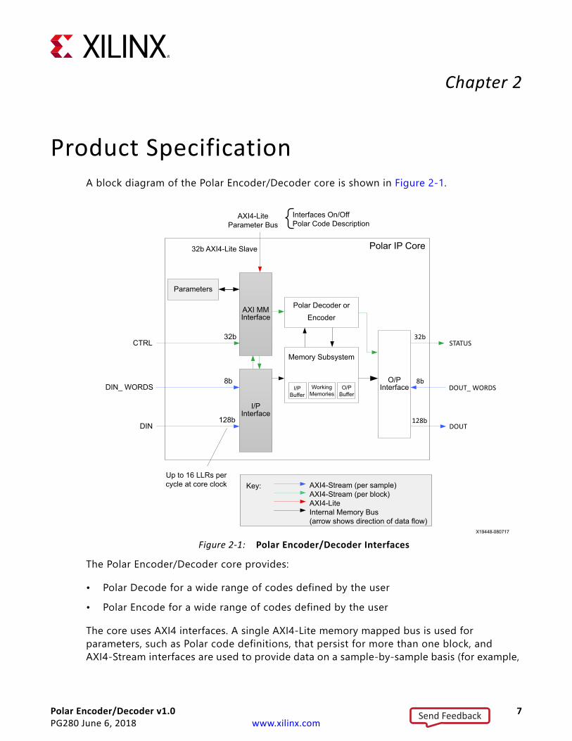
Product SpecificationA block diagram of the Polar Encoder/Decoder core is shown in Figure 2-1.
The Polar Encoder/Decoder core provides:
• Polar Decode for a wide range of codes defined by the user• Polar Encode for a wide range of codes defined by the user
The core uses AXI4 interfaces. A single AXI4-Lite memory mapped bus is used for parameters, such as Polar code definitions, that persist for more than one block, and AXI4-Stream interfaces are used to provide data on a sample-by-sample basis (for example,
X-Ref Target - Figure 2-1
Figure 2-1: Polar Encoder/Decoder Interfaces
Polar IP Core
AXI MMInterface
I/PInterface
Polar Decoder or Encoder
CTRL32b
DIN128b
32b
O/PInterface
STATUS
DOUT_ WORDS
DOUT
8b
128b
32b AXI4-Lite Slave
AXI4-Lite Parameter Bus
Up to 16 LLRs per cycle at core clock
Parameters
DIN_ WORDS 8b
Interfaces On/OffPolar Code Description
AXI4-Stream (per sample)AXI4-Stream (per block)AXI4-LiteInternal Memory Bus(arrow shows direction of data flow)
Key:
Memory Subsystem
I/P Buffer
Working Memories
O/P Buffer
X19448-080717
Send Feedback

Polar Encoder/Decoder v1.0 8PG280 June 6, 2018 www.xilinx.com
Chapter 2: Product Specification
DIN), or block-by-block basis (for example, CTRL). These interfaces provide handshake signals in addition to data. Further details are given in AXI4-Stream Interface. Data input and output buffers provide some scope to overlap input and output with encoder/decoder operation.
Each block is input through the data input interface (DIN) over a number of cycles. The amount of data transferred on each cycle is set by a separate data stream (DIN_WORDS) where a value is given per transaction on DIN. The output is generated in a similar way on the DOUT output stream, and similarly, the amount of data transferred is specified on the input data stream, DOUT_WORDS.
For each block, a single input is required on the control (CTRL) input stream, specifying the code to use and a user supplied ID field. One control word (transaction) is required for each data block, and data input stalls until the relevant control word is available. When decoded (or encoded), the output data is provided on DOUT along with a status word on the status (STATUS) output interface.
All AXI4-Stream interfaces contain valid and ready handshakes for flow control. Blocking either output (by deasserting ready) ultimately stops decoding and, when the input buffer is full, prevents further input. Figure 2-2 summarizes the data dependencies of the Polar Encoder/Decoder core. This shows that data input on DIN is dependent on CTRL and DIN_WORDS, and output on DOUT is dependent on DOUT_WORDS. However, there is delay between the input of CTRL and the associated input of DIN_WORDS and DIN input being accepted, indicated by the assertion of tready on each channel. Likewise, there is delay between DIN_WORDS and DIN. If the latency on DIN is to be minimized then the input of CTRL and DIN_WORDS should be provided in advance. Similarly, on the output, DOUT_WORDS (if required) should be driven as soon as possible to avoid any latency on DOUT. There are shallow buffers on the interfaces (as shown in Figure 2-2), which allow a small amount of data to be input on DIN and DOUT_WORDS before associated block control is provided on CTRL. This data is not processed by the Polar Encoder/Decoder core until the
X-Ref Target - Figure 2-2
Figure 2-2: Overview of Polar Encoder/Decoder Interface Dependencies
CTRL
DIN
DIN_WORDS
STATUS
DOUT
DOUT_WORDS
DIN input is dependent on availability of CTRL and DIN_WORDS
DOUT output is dependent on internal decoder output and DOUT_WORDS
STATUS is dependent on internal decoder output
Time
Decoder/EncoderLatency
First-in-to-first-out latency
X19449-100617
Send Feedback
Polar Encoder/Decoder v1.0 9PG280 June 6, 2018 www.xilinx.com
Chapter 2: Product Specification
latter is available. Another implication of these buffers is that DIN input can start at the same time as CTRL and DIN_WORDS are applied.
The use of AXI4-Stream data interfaces allows the core to limit data throughput to the rate that it can process. To maximize throughput you need only ensure that data is always available on the input, and that data is read from output whenever it is available, as indicated by the AXI4-Stream handshake signals. Alternatively, if throughput is to be controlled, then only the CTRL input can be regulated to the correct block throughput rate while the other interfaces operate as previously described—that is, they are regulated by the Polar Encoder/Decoder core itself. On all AXI4-Stream slave channels, TLAST should be asserted on the last transaction for a block or codeword. The core asserts TLAST for the last output transaction for a block or codeword.
Note: DIN_WORDS and DOUT_WORDS have a more advanced mode of operation, where the number of elements is specified for each transfer over DIN or DOUT.
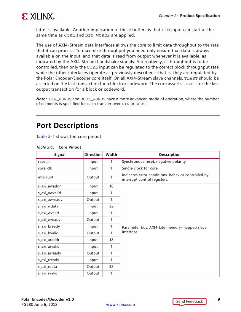
Port DescriptionsTable 2-1 shows the core pinout.
Table 2-1: Core PinoutSignal Direction Width Description
reset_n Input 1 Synchronous reset, negative polaritycore_clk Input 1 Single clock for core
interrupt Output 1 Indicates error conditions. Behavior controlled by interrupt control registers.
s_axi_awaddr Input 18
Parameter bus: AXI4-Lite memory-mapped slave interface
s_axi_awvalid Input 1s_axi_awready Output 1s_axi_wdata Input 32s_axi_wvalid Input 1s_axi_wready Output 1s_axi_bready Input 1s_axi_bvalid Output 1s_axi_araddr Input 18s_axi_arvalid Input 1s_axi_arready Output 1s_axi_rready Input 1s_axi_rdata Output 32s_axi_rvalid Output 1
Send Feedback

Polar Encoder/Decoder v1.0 10PG280 June 6, 2018 www.xilinx.com
Chapter 2: Product Specification
Parameter BusThe AXI4-Lite parameter bus allows two outstanding transactions on the write interface, and one outstanding transaction on the read interface. The higher number of outstanding transactions on the write interface improves the write download throughput, allowing a Polar code to be updated more quickly.
s_axis_din_words_tvalid Input 1
Controls number of bytes on data input bus: AXI4-Stream slave interface
s_axis_din_words_tready Output 1s_axis_din_words_tlast Input 1s_axis_din_words_tdata Input 8s_axis_ctrl_tvalid Input 1
Control input bus: AXI4-Stream slave interfaces_axis_ctrl_tready Output 1s_axis_ctrl_tdata Input 32s_axis_din_tvalid Input 1
Data input bus: AXI4-Stream slave interfaces_axis_din_tready Output 1s_axis_din_tlast Input 1s_axis_din_tdata Input 128m_axis_status_tvalid Output 1
Status output bus: AXI4-Stream master interfacem_axis_status_tready Input 1m_axis_status_tdata Output 32s_axis_dout_words_tvalid Input 1
Controls number of bytes on data output bus: AXI4-Stream slave interface
s_axis_dout_words_tready Output 1s_axis_dout_words_tlast Input 1s_axis_dout_words_tdata Input 8m_axis_dout_tvalid Output 1
Data output bus: AXI4-Stream master interfacem_axis_dout_tready Input 1m_axis_dout_tlast Output 1m_axis_dout_tdata Output 128
Table 2-1: Core Pinout (Cont’d)
Signal Direction Width Description
Send Feedback

Polar Encoder/Decoder v1.0 11PG280 June 6, 2018 www.xilinx.com
Chapter 2: Product Specification
Control AXI4-Stream SlaveThe AXI4-Stream control (CTRL) input provides information specific to each block as summarized by Table 2-2. The control interface is 32 bits.
Status AXI4-Stream MasterThe AXI4-Stream status (STATUS) output provides information specific to each block. The status interface is 32 bits.
Table 2-2: Control AXI4-Stream Slave (CTRL) Interface Definition for Polar DecodeField Bits Range Description
id 31:24 0 to 255 External block identifier to be passed through to status output23:9 - Reserved
early_termination 8 0 or 1 When set this enables Early Termination for this block.
blind_decode(1) 7 0 or 1
When enabled, the received CRC bits are appended to the information bits on output, and a candidate RNTI (Radio Network Temporary Identifier), the exclusive OR of the last 16 received CRC bits and calculated CRC bits, is output on the STATUS channel.
code 6:0 0 to 127 Code number (CODE) used to specify which set of Polar code parameters are to be used on the codeword.
Notes: 1. Blind decode is supported only for codes with ITLV = 1, AUGMENT set to CRC, CRC_INIT=1, and CRC_SEL = CRC24C.
The bit is ignored otherwise.
Table 2-3: Control AXI4-Stream Slave (CTRL) Interface Definition for Polar EncodeField Bits Range Description
id 31:24 0 to 255 External block identifier to be passed through to status output.
rnti 23:8 0 to 65535
Value of RNTI to be used in CRC masking. Set to 0 if not required. See 3GPP TS 38.212 V15.1.1 [Ref 10].
7 - Reserved
code 6:0 0 to 127 Code number (CODE) used to specify which set of Polar code parameters are to be used on the codeword.
Table 2-4: Status AXI4-Stream Master (STATUS) Interface Definition for Polar DecodeField Bits Range Description
id 31:24 0 to 255 External block identifier supplied from control input.23:18 - Reserved
early_terminated 17 0 or 1 Indicates that early termination occurred for this block when the value is 1.
Send Feedback

Polar Encoder/Decoder v1.0 12PG280 June 6, 2018 www.xilinx.com
Chapter 2: Product Specification
Data InterfacesSoft Value LLR RepresentationFor Polar decode, the soft value log-likelihood ratio is defined as:
Equation 2-1
As a consequence, negative LLR values are interpreted as hard binary value 0. Positive values (and 0) are interpreted as hard binary value 1.
Data Input AXI4-Stream Slave (DIN)• The DIN data input stream consists of a 128-bit bus.• Either bytes of soft value LLR (decode operation), or bytes of hard bits (encode
operation) are transferred over DIN.• Blocks are transferred over one or more cycles, starting with the least significant LLRs
or hard bits.• The number of bytes (LLRs or hard bits) transferred over DIN on each cycle is given by
the DIN_WORDS input. See Data Input Control AXI4-Stream Slave (DIN_WORDS) for details on how DIN_WORDS is used.
For example, if a symbol demapper is generating a number of LLR values associated with a particular level of modulation, it is possible to adjust the input to accommodate this.
parity_crc_pass 16 0 or 1 Indicates success (1) or failure (0) of parity or CRC for output block.
rnti 15:0 0 to 65535The exclusive OR of the last 16 received CRC bits and the last 16 calculated CRC bits, that is, the candidate RNTI value for blind decode. See 3GPP TS 38.212 V15.1.1 [Ref 10].
Table 2-5: Status AXI4-Stream Master (STATUS) Interface Definition for Polar EncodeField Bits Range Description
id 31:24 0 to 255 External block identifier supplied from control input.23:7 Reserved
code 6:0 0 to 127 Code number (CODE) specifying the Polar code parameters used to encode the block.
Table 2-4: Status AXI4-Stream Master (STATUS) Interface Definition for Polar Decode (Cont’d)
Field Bits Range Description
LLR x( ) Pr x 1=( )Pr x 0=( )-------------------- ln=
Send Feedback

Polar Encoder/Decoder v1.0 13PG280 June 6, 2018 www.xilinx.com
Chapter 2: Product Specification
• Each transfer can only contain one block; a block must complete before the next can start. If the block length is not a multiple of DIN_WORDS, then on the final transfer the core internally corrects the value of DIN_WORDS used. The core enforces this internally, overriding the input to ensure that the block completes, so that the next block input can start on the next AXI4-Stream transaction.
Soft Value Input for Polar Decode
If the operation is decode, the information on the DIN input stream is soft value LLRs as described in Table 2-6.
Hard Input for Polar Encode
When encoding, only hard data is input. This is provided in bytes, with up to 16 bytes transferred per cycle.
Only the information bits (which consists of K bits) must be provided. To aid integration, the DIN_TLAST input for this interface should be driven with a 1 for the last transfer of a block. This input is not used to synchronize of the input, but it is checked and an interrupt is available to signal inconsistencies.
Table 2-6: Soft Value LLR Data Input AXI4-Stream Slave (DIN) Interface DefinitionField Bits Range(1) Description(2)
llr(0) 7:0 -31.75 to 31.75 (10000001 to
01111111)
The input LLRs are 8 bit signed twos complement with two fractional bits. The input LLRs are assumed to be saturated to the given range, that is, the most negative twos complement number is not permitted.
llr(1) 15:8llr(2) 23:16
...llr(15) 127:120 -31.75 to 31.75 LLR, 2 fractional bits, externally saturated to given range.
Notes: 1. The LLR range depends on the scaling applied to the LLR prior to input. This range can be tuned to provide
improved performance within the system, and two fractional bits should be viewed simply as the default.2. The LLR input for Polar decode is assumed to be externally symmetrically saturated to 8 bits. If this is not done,
there might be performance degradation as the value -32 is internally saturated to -31.75.
Table 2-7: Data Input AXI4-Stream Slave (DIN) Interface Definition for Hard BitsField Bits Description
hbyte(0) 7:0 Bits m(7:0) to be encodedhbyte(1) 15:8 Bits m(15:8) to be encodedhbyte(2) 23:16 Bits m(23:16) to be encoded
…hbyte(15) 127:120 Bits m(127:120) to be encoded
Send Feedback
Polar Encoder/Decoder v1.0 14PG280 June 6, 2018 www.xilinx.com
Chapter 2: Product Specification
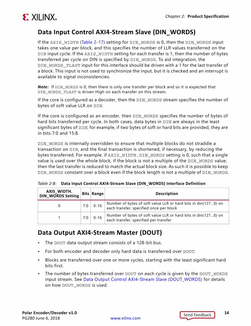
Data Input Control AXI4-Stream Slave (DIN_WORDS)If the AXIS_WIDTH (Table 2-17) setting for DIN_WORDS is 0, then the DIN_WORDS input takes one value per block, and this specifies the number of LLR values transferred on the DIN input cycle. If the AXIS_WIDTH setting for each transfer is 1, then the number of bytes transferred per cycle on DIN is specified by DIN_WORDS. To aid integration, the DIN_WORDS_TLAST input for this interface should be driven with a 1 for the last transfer of a block. This input is not used to synchronize the input, but it is checked and an interrupt is available to signal inconsistencies.
Note: If DIN_WORDS is 0, then there is only one transfer per block and so it is expected that DIN_WORDS_TLAST is driven High on each transfer on this stream.
If the core is configured as a decoder, then the DIN_WORDS stream specifies the number of bytes of soft value LLR on DIN.
If the core is configured as an encoder, then DIN_WORDS specifies the number of bytes of hard bits transferred per cycle. In both cases, data bytes in DIN are always in the least significant bytes of DIN; for example, if two bytes of soft or hard bits are provided, they are in bits 7:0 and 15:8.
DIN_WORDS is internally overridden to ensure that multiple blocks do not straddle a transaction on DIN, and the final transaction is shortened, if necessary, by reducing the bytes transferred. For example, if AXIS_WIDTH.DIN_WORDS setting is 0, such that a single value is used over the whole block, if the block is not a multiple of the DIN_WORDS value, then the last transfer is reduced to match the actual block size. As such it is possible to keep DIN_WORDS constant over a block even if the block length is not a multiple of DIN_WORDS.
Data Output AXI4-Stream Master (DOUT)• The DOUT data output stream consists of a 128-bit bus.• For both encoder and decoder only hard data is transferred over DOUT.• Blocks are transferred over one or more cycles, starting with the least significant hard
bits first.• The number of bytes transferred over DOUT on each cycle is given by the DOUT_WORDS
input stream. See Data Output Control AXI4-Stream Slave (DOUT_WORDS) for details on how DOUT_WORDS is used.
Table 2-8: Data Input Control AXI4-Stream Slave (DIN_WORDS) Interface DefinitionAXIS_WIDTH.
DIN_WORDS Setting Bits Range Description
0 7:0 0-16 Number of bytes of soft value LLR or hard bits in din(127…0) on each transfer, specified once per block
1 7:0 0-16 Number of bytes of soft value LLR or hard bits in din(127…0) on each transfer, specified per transfer
Send Feedback

Polar Encoder/Decoder v1.0 15PG280 June 6, 2018 www.xilinx.com
Chapter 2: Product Specification
• Data bytes are transferred in the least significant bytes of DOUT. For example, if DOUT_WORDS specifies two bytes are transferred, then these bytes are in locations 7:0 and 15:8.
• Each transfer can only contain one block; one block must complete before the next block can start.
Hard Output for Polar Decode and Encode
For the Polar encoder and decoder only hard data is output. This is provided in bytes, with up to 16 bytes transferred per cycle, dependent on the setting of AXIS_WIDTH.DOUT parameter as summarized by Table 2-9.
Data Output Control AXI4-Stream Slave (DOUT_WORDS)If the AXIS_WIDTH parameter setting for the DOUT_WORDS field is 0, then the DOUT_WORDS input takes one value per block, and this specifies the number of bytes of hard bits transferred on DOUT.
If the AXIS_WIDTH parameter setting for DOUT_WORDS field is 1, then the number of bytes transferred per cycle on DOUT is specified on a transfer-by-transfer basis by DOUT_WORDS. To aid integration the DOUT_WORDS_TLAST input for this interface should be driven with a 1 for the last transfer of a block. This input is not used to synchronize output, but it is checked and an interrupt is available to signal inconsistencies.
Note: If DOUT_WORDS is 0, then there is only one transfer per block and so it is expected that DOUT_WORDS_TLAST is driven High on each transfer on this stream.
DOUT_WORDS is internally overridden to ensure that multiple blocks do not straddle a transaction on DOUT (the final transaction is shortened, if necessary, in the same way as for DIN_WORDS as described in Data Input Control AXI4-Stream Slave (DIN_WORDS)). As such it is possible to keep DOUT_WORDS constant over a block even if the block length is not a multiple of DOUT_WORDS.
If DOUT_WORDS_TLAST is not being used, then TLAST interrupts can be masked on this interface to avoid unnecessary interrupts (see Interrupt Mask Register Table 2-22).
Table 2-9: Data Output AXI4-Stream Master (DOUT) Interface Definition for Hard BitsField Bits Description
hbyte(0) 7:0 Bits m(7:0)hbyte(1) 15:8 Bits m(15:8)hbyte(2) 23:16 Bits m(23:16)…hbyte(15) 127:120 Bits m(127:120)
Send Feedback

Polar Encoder/Decoder v1.0 16PG280 June 6, 2018 www.xilinx.com
Chapter 2: Product Specification
Throughput Limits of InterfacesThe throughput of the input and output interfaces is limited to a maximum of:
• Polar encode and decode: 16 hard bytes @f(core_clk)
Polar Decoder Interface Throughput Limit
For the decode, all internal transfers into internal input memory are 16 LLR words. Because all supported block sizes are a multiple of 16, maximum interface throughput is therefore simply 16* fcore_clk LLRs per second.
Polar Encoder Interface Throughput Limit
For the encoder, transfers are at most 16 bytes, or 128 bits. If K<128 then at most K bits are transferred between interface and memory per cycle and the average I/O throughput becomes:
Gb/s Equation 2-2
For example, if K = 200, then peak hard bits I/O B/W is:
(for example, 40 Gb/s at fcore_clock = 400 MHz)
Note that this describes only interface throughput. For both encoder and decoder, core throughput is limited by internal mechanisms.
AXI4-Stream InterfaceThe AXI4-Stream interface is a point to point link where the transmitter is known as a master, and the receiver a slave. For further details on AXI4-Stream interfaces see the AMBA® AXI4-Stream Protocol Specification (Arm IHI 0051A) [Ref 8] and the Vivado Design Suite AXI Reference Guide (UG1037) [Ref 9].
Table 2-10: Data Output Control AXI4-Stream Slave (DOUT_WORDS) Interface DefinitionAXIS_WIDTH.
DOUT_WORDS Setting Bits Range Description
0 7:0 0-16 Number of bytes of soft value LLR or hard bits in dout(127…0) on each transfer, specified once per block
1 7:0 0-16 Number of bytes of soft value LLR or hard bits in dout(127…0) on each transfer, specified per transfer
hard bits I/O B/W KK
128--------------------- fcore_clk×=
hard bits I/O B/W 200200128--------
------------- fcore_clk×=
Send Feedback
Polar Encoder/Decoder v1.0 17PG280 June 6, 2018 www.xilinx.com
Chapter 2: Product Specification
Basic Handshake
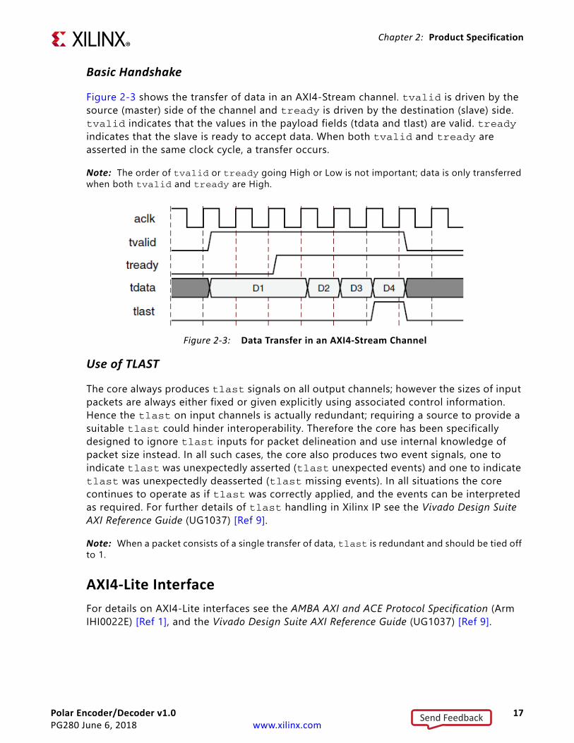
Figure 2-3 shows the transfer of data in an AXI4-Stream channel. tvalid is driven by the source (master) side of the channel and tready is driven by the destination (slave) side. tvalid indicates that the values in the payload fields (tdata and tlast) are valid. tready indicates that the slave is ready to accept data. When both tvalid and tready are asserted in the same clock cycle, a transfer occurs.
Note: The order of tvalid or tready going High or Low is not important; data is only transferred when both tvalid and tready are High.
Use of TLAST
The core always produces tlast signals on all output channels; however the sizes of input packets are always either fixed or given explicitly using associated control information. Hence the tlast on input channels is actually redundant; requiring a source to provide a suitable tlast could hinder interoperability. Therefore the core has been specifically designed to ignore tlast inputs for packet delineation and use internal knowledge of packet size instead. In all such cases, the core also produces two event signals, one to indicate tlast was unexpectedly asserted (tlast unexpected events) and one to indicate tlast was unexpectedly deasserted (tlast missing events). In all situations the core continues to operate as if tlast was correctly applied, and the events can be interpreted as required. For further details of tlast handling in Xilinx IP see the Vivado Design Suite AXI Reference Guide (UG1037) [Ref 9].
Note: When a packet consists of a single transfer of data, tlast is redundant and should be tied off to 1.
AXI4-Lite InterfaceFor details on AXI4-Lite interfaces see the AMBA AXI and ACE Protocol Specification (Arm IHI0022E) [Ref 1], and the Vivado Design Suite AXI Reference Guide (UG1037) [Ref 9].
X-Ref Target - Figure 2-3
Figure 2-3: Data Transfer in an AXI4-Stream Channel
Send Feedback

Polar Encoder/Decoder v1.0 18PG280 June 6, 2018 www.xilinx.com
Chapter 2: Product Specification
StandardsThe Polar Encoder/Decoder core provides Polar codes defined in the following standard:
° 3GPP TS 38.212 V15.1.1 Multiplexing and channel coding (Release 15) [Ref 10]
PerformanceFor full details about performance and resource utilization, visit the Performance and Resource Utilization web page.
Performance Considerations
Encode
The Polar encoder throughput is defined as the number of information bits input per second; throughput is strongly related to code rate (K/N) because most delays in the encoder are related to N. Latency is defined as the first transfer in of a block to the first transfer out of the same block. Table 2-11 shows throughput and latency for the encoder for various block descriptions.
The latency figures shown are the latencies seen by blocks after reset. In the event that blocks are input to the core faster than the maximum achievable throughput, then blocks are buffered internally, pending the availability of the encoder. The waiting time in this internal buffer adds to the latency. For instance, with blocks of size N=512, 16 blocks can be accepted at startup. The first eight of these enter the encoder immediately and see a
Table 2-11: Encoder Throughput and Latency
N K Augment CRC_SEL Number of Parity Bits
PerformanceThroughput (Mb/s) Latency (µs)
1024 200 BOTH CRC11 3 720.721 0.5621024 200 CRC CRC24C 0 720.721 0.5621024 200 PARITY N/A 3 733.945 0.5571024 512 BOTH CRC24C 3 1329.87 0.655256 40 CRC CRC24C 0 266.667 0.29512 140 CRC CRC24C 0 666.667 0.395512 40 CRC CRC24C 0 250 0.345
Notes: 1. Measurements shown are for BRAM configuration. With Distributed RAM, performance is identical or slightly
improved.
Send Feedback

Polar Encoder/Decoder v1.0 19PG280 June 6, 2018 www.xilinx.com
Chapter 2: Product Specification
latency as per Table 2-11. The second eight blocks do not begin encoding until the first eight have been processed and so experience greater latency. Therefore to achieve minimal latency the input rate to the core must be regulated.
Decode
The Polar decoder throughput is defined as the number of information bits output per second. Latency is defined as the first transfer in of a block to the first transfer out of the same block.
The Polar decoder interlaces blocks internally to maximize use of the decode hardware. The time to decode a block is influenced by the presence of other blocks also being decoded. Table 2-12 shows decoder throughput and latency for various code descriptions.
The latency figures shown in Table 2-12 are the latencies seen by blocks after reset. In the event that blocks are input to the core faster than the maximum achievable throughput, then blocks are buffered internally, pending the availability of the decoder. The waiting time in this internal buffer adds to the latency. For instance, with blocks of size N=1024, 16 blocks can be accepted at startup. The first eight of these enter the decoder immediately and see a latency as per Table 2-12. The second eight blocks do not begin decoding until the first eight have been processed and so experience greater latency. Therefore to achieve minimal latency the input rate to the core must be regulated.
Table 2-12: Decoder Throughput and Latency
N K Augment CRC_SEL Number of Parity Bits
PerformanceThroughput (Mb/s) Latency (µs)
1024 200 BOTH CRC6 3 84.211 19.041024 200 CRC CRC24C 0 84.537 19.0921024 200 PARITY N/A 3 85.68 18.7231024 512 BOTH CRC6 3 158.57 25.875256 40 CRC CRC24C 0 74.941 4.27512 140 CRC CRC24C 0 120.409 9.312512 40 CRC CRC24C 0 51.454 6.33
Notes: 1. Measurements shown are for BRAM configuration. With Distributed RAM, performance is identical or slightly
improved.
Send Feedback

Polar Encoder/Decoder v1.0 20PG280 June 6, 2018 www.xilinx.com
Chapter 2: Product Specification
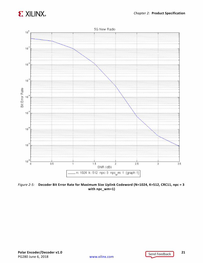
BER PerformanceThe following plots have been generated using the example design in hardware using QPSK modulation and LLR demodulation. For each point, groups of 10,000 blocks are run until at least 50 bit errors have been seen. Codes were constructed using the construction function provided with the C model.
X-Ref Target - Figure 2-4
Figure 2-4: Decoder Frame Error Rate for Maximum Size Uplink Codeword (N=1024, K=512, CRC11, npc = 3 with npc_wm=1)
Send Feedback
Polar Encoder/Decoder v1.0 21PG280 June 6, 2018 www.xilinx.com
Chapter 2: Product Specification
X-Ref Target - Figure 2-5
Figure 2-5: Decoder Bit Error Rate for Maximum Size Uplink Codeword (N=1024, K=512, CRC11, npc = 3 with npc_wm=1)
Send Feedback

Polar Encoder/Decoder v1.0 22PG280 June 6, 2018 www.xilinx.com
Chapter 2: Product Specification
X-Ref Target - Figure 2-6
Figure 2-6: Decoder Bit Error Rate for Maximum Size Downlink Codeword (N = 512, K = 140, CRC24C, ITLV = 1, CRC_INIT = 1)
Send Feedback

Polar Encoder/Decoder v1.0 23PG280 June 6, 2018 www.xilinx.com
Chapter 2: Product Specification
X-Ref Target - Figure 2-7
Figure 2-7: Decoder Frame Error Rate for Maximum Size Downlink Codeword (N = 512, K = 140, CRC24C, ITLV = 1, CRC_INIT = 1)
Send Feedback

Polar Encoder/Decoder v1.0 24PG280 June 6, 2018 www.xilinx.com
Chapter 2: Product Specification
X-Ref Target - Figure 2-8
Figure 2-8: Decoder Frame Error Rate for Example Uplink Codeword Size (N=1024, K=200, CRC11, npc=3 with npc_wm=1)
Send Feedback

Polar Encoder/Decoder v1.0 25PG280 June 6, 2018 www.xilinx.com
Chapter 2: Product Specification
Register SpaceIMPORTANT: Registers should be programmed through a device driver (this generates correct values from simple definitions of Polar codes). The driver is provided by Xilinx.
The register map consists of the following types of parameters:
• Core Parameters (common to all codes)• Polar Code Parameters (per code)
X-Ref Target - Figure 2-9
Figure 2-9: Decoder Bit Error Rate for Example Uplink Codeword Size (N=1024, K=200, CRC11, npc=3 with npc_wm=1)
Send Feedback

Polar Encoder/Decoder v1.0 26PG280 June 6, 2018 www.xilinx.com
Chapter 2: Product Specification
All registers start on 32-bit word aligned addresses. The two LSBs of the read and write addresses are assumed to be zero.
Register read write access restrictions are summarized under the following sections. Further details of how code parameters might be managed are provided under Parameter Management.
Core ParametersReadable core parameters can be read at any time when the core is out of reset.
Note: Any restrictions regarding when a core parameter can be written, are provided as footnotes in the relevant parameter tables.
Table 2-13: Register SpaceAddress (Hex) Register Name
__Core Parameters0x00 AXI_WR_PROTECT Register (0x00)0x04 CODE_WR_PROTECT Register (0x04)0x08 ACTIVE Register (0x08)0x0C AXIS_WIDTH Register (0x0C)0x10 AXIS_ENABLE Register (0x10)0x1C Interrupt Status Register (ISR) (0x1C)0x20 Interrupt Enable Register (IER) (0x20)0x24 Interrupt Disable Register (IDR) (0x24)0x28 Interrupt Mask Register (IMR) (0x28)0x2C ECC Interrupt Status Register (0x2C)0x30 ECC Interrupt Enable Register (0x30)0x34 ECC Interrupt Disable Register (0x34)0x38 ECC Interrupt Mask Register (0x38)0x40 Version Register (0x40)
Polar Code Parameters0x2000+CODE*0x10 REG0 Register (0x2000+CODE*0x10)0x2004+CODE*0x10 REG1 Register (0x2004+CODE*0x10)0x2008+CODE*0x10 REG2 Register (0x2008+CODE*0x10)0x200C+CODE*0x10 REG3 Register (0x200C+CODE*0x10)
0x10000–0x10FFC Bit Allocation Table (BA_TABLE) (0x10000–0x10FFC)
Send Feedback
Polar Encoder/Decoder v1.0 27PG280 June 6, 2018 www.xilinx.com
Chapter 2: Product Specification
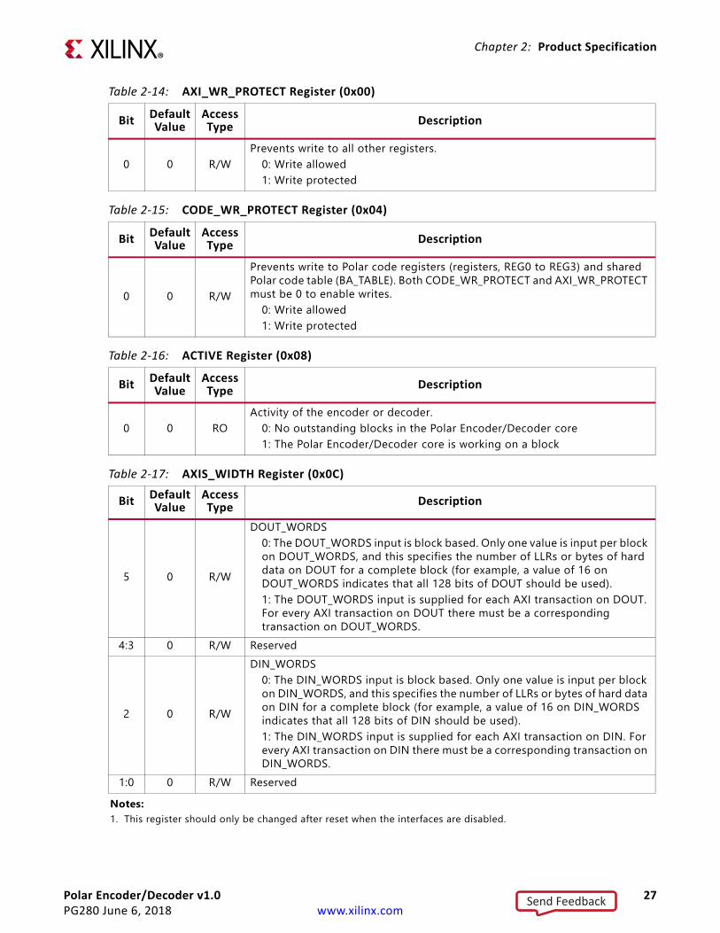
Table 2-14: AXI_WR_PROTECT Register (0x00)
Bit DefaultValue
Access Type Description
0 0 R/WPrevents write to all other registers.
0: Write allowed1: Write protected
Table 2-15: CODE_WR_PROTECT Register (0x04)
Bit DefaultValue
Access Type Description
0 0 R/W
Prevents write to Polar code registers (registers, REG0 to REG3) and shared Polar code table (BA_TABLE). Both CODE_WR_PROTECT and AXI_WR_PROTECT must be 0 to enable writes.
0: Write allowed1: Write protected
Table 2-16: ACTIVE Register (0x08)
Bit DefaultValue
Access Type Description
0 0 ROActivity of the encoder or decoder.
0: No outstanding blocks in the Polar Encoder/Decoder core1: The Polar Encoder/Decoder core is working on a block
Table 2-17: AXIS_WIDTH Register (0x0C)
Bit DefaultValue
Access Type Description
5 0 R/W
DOUT_WORDS0: The DOUT_WORDS input is block based. Only one value is input per block on DOUT_WORDS, and this specifies the number of LLRs or bytes of hard data on DOUT for a complete block (for example, a value of 16 on DOUT_WORDS indicates that all 128 bits of DOUT should be used).1: The DOUT_WORDS input is supplied for each AXI transaction on DOUT. For every AXI transaction on DOUT there must be a corresponding transaction on DOUT_WORDS.
4:3 0 R/W Reserved
2 0 R/W
DIN_WORDS0: The DIN_WORDS input is block based. Only one value is input per block on DIN_WORDS, and this specifies the number of LLRs or bytes of hard data on DIN for a complete block (for example, a value of 16 on DIN_WORDS indicates that all 128 bits of DIN should be used).1: The DIN_WORDS input is supplied for each AXI transaction on DIN. For every AXI transaction on DIN there must be a corresponding transaction on DIN_WORDS.
1:0 0 R/W ReservedNotes: 1. This register should only be changed after reset when the interfaces are disabled.
Send Feedback

Polar Encoder/Decoder v1.0 28PG280 June 6, 2018 www.xilinx.com
Chapter 2: Product Specification
Table 2-18: AXIS_ENABLE Register (0x10)
Bit DefaultValue
Access Type Description
5 0 R/WDOUT_WORDS: Deasserts ready out and valid internally on DOUT_WORDS to disable input.
0: Disabled1: Enabled
4 0 R/WDOUT: Deasserts valid out and ready internally on DOUT to disable output.
0: Disabled1: Enabled
3 0 R/WSTATUS: Deasserts valid out and ready internally on STATUS to disable output.
0: Disabled1: Enabled
2 0 R/WDIN_WORDS: Deasserts ready out and valid internally on DIN_WORDS to disable input.
0: Disabled1: Enabled
1 0 R/WDIN: Deasserts ready out and valid internally on DIN to disable input.
0: Disabled1: Enabled
0 0 R/WCTRL: Deasserts ready out and valid internally on CTRL to disable input.
0: Disabled1: Enabled
Table 2-19: Interrupt Status Register (ISR) (0x1C)
Bit(1) DefaultValue
Access Type Description
6 0 R/W Invalid codeword(2)
5 0 R/W DOUT_WORDS tlast unexpected4 0 R/W DOUT_WORDS tlast missing3 0 R/W DIN_WORDS tlast unexpected2 0 R/W DIN_WORDS tlast missing1 0 R/W DIN tlast unexpected0 0 R/W DIN tlast missing
Notes: 1. Write 1 to respective bit to clear.2. See Interrupt for invalid codeword definition.3. This register reflects the raw interrupt status and is not masked by the IMR.
Table 2-20: Interrupt Enable Register (IER) (0x20)
Bit(1) DefaultValue
Access Type Description
6 0 WO Invalid codeword(2)
5 0 WO DOUT_WORDS tlast unexpected
Send Feedback

Polar Encoder/Decoder v1.0 29PG280 June 6, 2018 www.xilinx.com
Chapter 2: Product Specification
.
4 0 WO DOUT_WORDS tlast missing3 0 WO DIN_WORDS tlast unexpected2 0 WO DIN_WORDS tlast missing1 0 WO DIN tlast unexpected0 0 WO DIN tlast missing
Notes: 1. Read 0. Write 1 to respective bit to enable interrupt (respective bit of IMR is set to 0). Write 0 ignored.2. See Interrupt for invalid codeword definition.
Table 2-21: Interrupt Disable Register (IDR) (0x24)
Bit(1) DefaultValue
Access Type Description
6 0 WO Invalid codeword(2)
5 0 WO DOUT_WORDS tlast unexpected4 0 WO DOUT_WORDS tlast missing3 0 WO DIN_WORDS tlast unexpected2 0 WO DIN_WORDS tlast missing1 0 WO DIN tlast unexpected0 0 WO DIN tlast missing
Notes: 1. Read 0. Write 1 to respective bit to disable interrupt (respective bit of IMR is set to 1). Write 0 ignored.2. See Interrupt for invalid codeword definition.
Table 2-22: Interrupt Mask Register (IMR) (0x28)
Bit DefaultValue
Access Type Description
6 0 RO Invalid codeword(2)
5 1 RO DOUT_WORDS tlast unexpected4 1 RO DOUT_WORDS tlast missing3 1 RO DIN_WORDS tlast unexpected2 1 RO DIN_WORDS tlast missing1 1 RO DIN tlast unexpected0 1 RO DIN tlast missing
Notes: 1. If mask bit is set, then interrupt is masked, that is, it does not cause the interrupt pin to go High.2. See Interrupt for invalid codeword definition.
Table 2-20: Interrupt Enable Register (IER) (0x20) (Cont’d)
Bit(1) DefaultValue
Access Type Description
Send Feedback

Polar Encoder/Decoder v1.0 30PG280 June 6, 2018 www.xilinx.com
Chapter 2: Product Specification
Table 2-23: ECC Interrupt Status Register (0x2C)
Bit(1) DefaultValue
Access Type Description(2)
11 0 R/W Polar BA_TABLE memory bank 1 ECC two-bit error(3)
10 0 R/W Polar BA_TABLE memory bank 2 ECC two-bit error9 0 R/W Polar code REG3 memory ECC two-bit error8 0 R/W Polar code REG2 memory (reserved) ECC two-bit error7 0 R/W Polar code REG1 memory ECC two-bit error6 0 R/W Polar code REG0 memory ECC two-bit error5 0 R/W Polar BA_TABLE memory bank 1 ECC event(4)
4 0 R/W Polar BA_TABLE memory bank 2 ECC event3 0 R/W Polar code REG3 memory ECC event2 0 R/W Polar code REG2 memory (reserved) ECC event1 0 R/W Polar code REG1 memory ECC event0 0 R/W Polar code REG0 memory ECC event
Notes: 1. Write 1 to respective bit to clear.2. This register reflects the raw interrupt status and is not masked by the IMR.3. The ECC two-bit error register is set when two errors are detected within a word read from the respective memory.
It can also be set when the number of errors in a word is greater than two—however, this is not guaranteed. Uncorrected multi-bit errors can result in incorrect core behavior. A core reset is recommended, followed by re-programming of the Polar code parameters.
4. An ECC event is when one or more errors have been detected in a word read from the respective memory. If present without an ECC two-bit error then only a single error has been detected, which has been corrected. To avoid this potentially becoming an uncorrectable multi-bit error at a later time the memory contents should be refreshed.
Send Feedback

Polar Encoder/Decoder v1.0 31PG280 June 6, 2018 www.xilinx.com
Chapter 2: Product Specification
Table 2-24: ECC Interrupt Enable Register (0x30)
Bit(1) DefaultValue
Access Type Description
11 0 WO Polar BA_TABLE memory bank 1 ECC two-bit error(2)
10 0 WO Polar BA_TABLE memory bank 2 ECC two-bit error9 0 WO Polar code REG3 memory ECC two-bit error8 0 WO Polar code REG2 memory (reserved) ECC two-bit error7 0 WO Polar code REG1 memory ECC two-bit error6 0 WO Polar code REG0 memory ECC two-bit error5 0 WO Polar BA_TABLE memory bank 1 ECC event(3)
4 0 WO Polar BA_TABLE memory bank 2 ECC event3 0 WO Polar code REG3 memory ECC event2 0 WO Polar code REG2 memory (reserved) ECC event1 0 WO Polar code REG1 memory ECC event0 0 WO Polar code REG0 memory ECC event
Notes: 1. Read 0. Write 1 to respective bit to enable interrupt (respective bit of ECC Interrupt Mask register is set to 0). Write
0 ignored.2. The ECC two-bit error register is set when two errors are detected within a word read from the respective memory.
It can also be set when the number of errors in a word is greater than two—however, this is not guaranteed. Uncorrected multi-bit errors can result in incorrect core behavior. A core reset is recommended, followed by re-programming of the Polar code parameters.
3. An ECC event is when one or more errors have been detected in a word read from the respective memory. If present without an ECC two-bit error then only a single error has been detected, which has been corrected. To avoid this potentially becoming an uncorrectable multi-bit error at a later time the memory contents should be refreshed.
Table 2-25: ECC Interrupt Disable Register (0x34)
Bit(1) DefaultValue
Access Type Description
11 0 WO Polar BA_TABLE memory bank 1 ECC two-bit error(2)
10 0 WO Polar BA_TABLE memory bank 2 ECC two-bit error9 0 WO Polar code REG3 memory ECC two-bit error8 0 WO Polar code REG2 memory (reserved) ECC two-bit error7 0 WO Polar code REG1 memory ECC two-bit error6 0 WO Polar code REG0 memory ECC two-bit error5 0 WO Polar BA_TABLE memory bank 1 ECC event(3)
4 0 WO Polar BA_TABLE memory bank 2 ECC event
Send Feedback

Polar Encoder/Decoder v1.0 32PG280 June 6, 2018 www.xilinx.com
Chapter 2: Product Specification
3 0 WO Polar code REG3 memory ECC event2 0 WO Polar code REG2 memory (reserved) ECC event1 0 WO Polar code REG1 memory ECC event0 0 WO Polar code REG0 memory ECC event
Notes: 1. Read 0. Write 1 to respective bit to disable interrupt (respective bit of ECC Interrupt Mask register is set to 1). Write
0 ignored.2. The ECC two-bit error register is set when two errors are detected within a word read from the respective memory.
It can also be set when the number of errors in a word is greater than two—however, this is not guaranteed. Uncorrected multi-bit errors can result in incorrect core behavior. A core reset is recommended, followed by re-programming of the Polar code parameters.
3. An ECC event is when one or more errors have been detected in a word read from the respective memory. If present without an ECC two-bit error then only a single error has been detected, which has been corrected. To avoid this potentially becoming an uncorrectable multi-bit error at a later time the memory contents should be refreshed.
Table 2-26: ECC Interrupt Mask Register (0x38)
Bit(1) DefaultValue
Access Type Description
11 1 RO Polar BA_TABLE memory bank 1 ECC two-bit error(2)
10 1 RO Polar BA_TABLE memory bank 2 ECC two-bit error9 1 RO Polar code REG3 memory ECC two-bit error8 1 RO Polar code REG2 memory (reserved) ECC two-bit error7 1 RO Polar code REG1 memory ECC two-bit error6 1 RO Polar code REG0 memory ECC two-bit error5 1 RO Polar BA_TABLE memory bank 1 ECC event(3)
4 1 RO Polar BA_TABLE memory bank 2 ECC event3 1 RO Polar code REG3 memory ECC event2 1 RO Polar code REG2 memory (reserved) ECC event1 1 RO Polar code REG1 memory ECC event0 1 RO Polar code REG0 memory ECC event
Notes: 1. If mask bit is set, then interrupt is masked, that is, it does not cause the interrupt pin to go High.2. The ECC two-bit error register is set when two errors are detected within a word read from the respective memory.
It can also be set when the number of errors in a word is greater than two—however, this is not guaranteed. Uncorrected multi-bit errors can result in incorrect core behavior. A core reset is recommended, followed by re-programming of the Polar code parameters.
3. An ECC event is when one or more errors have been detected in a word read from the respective memory. If present without an ECC two-bit error then only a single error has been detected, which has been corrected. To avoid this potentially becoming an uncorrectable multi-bit error at a later time the memory contents should be refreshed.
Table 2-25: ECC Interrupt Disable Register (0x34) (Cont’d)
Bit(1) DefaultValue
Access Type Description
Send Feedback
Polar Encoder/Decoder v1.0 33PG280 June 6, 2018 www.xilinx.com
Chapter 2: Product Specification
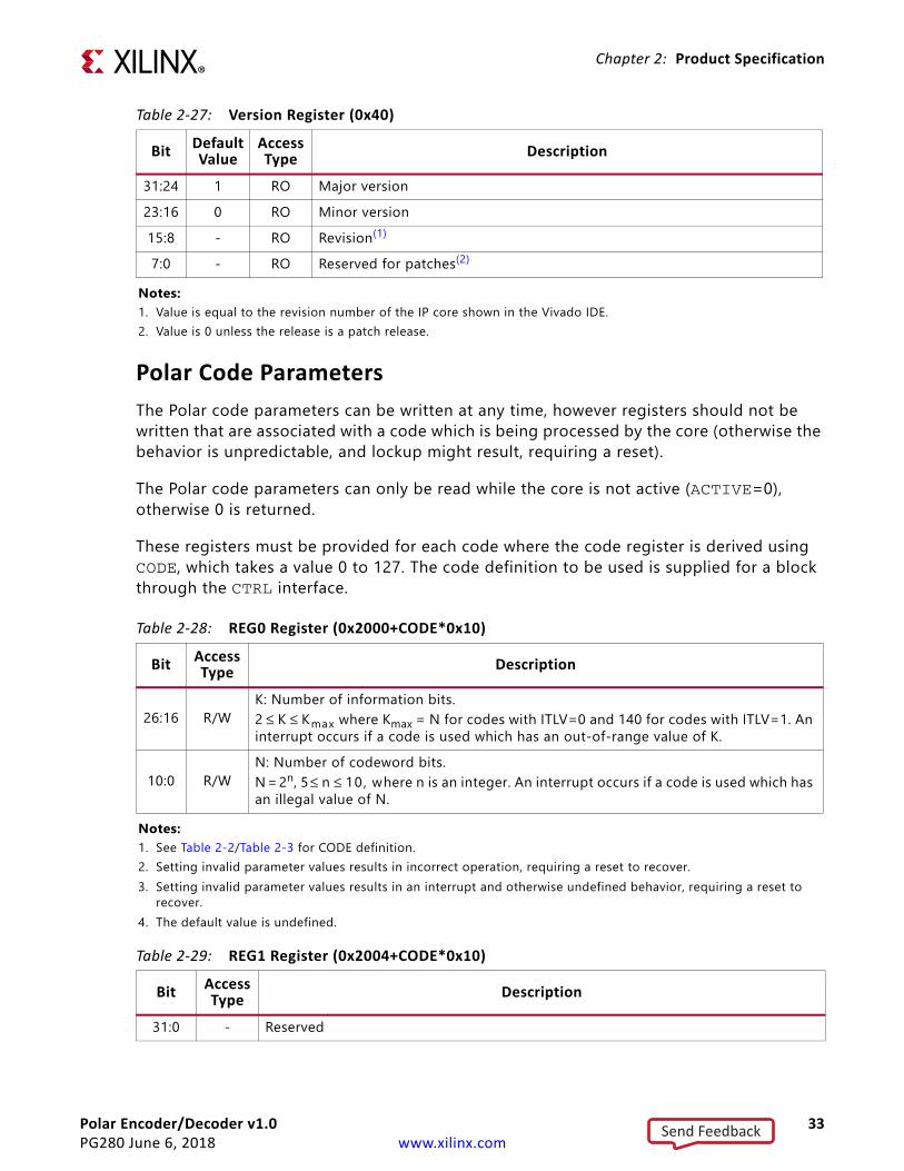
Polar Code ParametersThe Polar code parameters can be written at any time, however registers should not be written that are associated with a code which is being processed by the core (otherwise the behavior is unpredictable, and lockup might result, requiring a reset).
The Polar code parameters can only be read while the core is not active (ACTIVE=0), otherwise 0 is returned.
These registers must be provided for each code where the code register is derived using CODE, which takes a value 0 to 127. The code definition to be used is supplied for a block through the CTRL interface.
Table 2-27: Version Register (0x40)
Bit DefaultValue
Access Type Description
31:24 1 RO Major version23:16 0 RO Minor version15:8 - RO Revision(1)
7:0 - RO Reserved for patches(2)
Notes: 1. Value is equal to the revision number of the IP core shown in the Vivado IDE.2. Value is 0 unless the release is a patch release.
Table 2-28: REG0 Register (0x2000+CODE*0x10)
Bit Access Type Description
26:16 R/WK: Number of information bits.2 ≤ K ≤ Kmax where Kmax = N for codes with ITLV=0 and 140 for codes with ITLV=1. An interrupt occurs if a code is used which has an out-of-range value of K.
10:0 R/WN: Number of codeword bits.N = 2n, 5 ≤ n ≤ 10, where n is an integer. An interrupt occurs if a code is used which has an illegal value of N.
Notes: 1. See Table 2-2/Table 2-3 for CODE definition.2. Setting invalid parameter values results in incorrect operation, requiring a reset to recover.3. Setting invalid parameter values results in an interrupt and otherwise undefined behavior, requiring a reset to
recover.4. The default value is undefined.
Table 2-29: REG1 Register (0x2004+CODE*0x10)
Bit Access Type Description
31:0 - Reserved
Send Feedback

Polar Encoder/Decoder v1.0 34PG280 June 6, 2018 www.xilinx.com
Chapter 2: Product Specification
Not all combinations of AUGMENT, CRC_SEL, ITLV, and CRC_INIT are supported. Unsupported combinations might result in the assertion of an interrupt due to an invalid codeword (see Interrupt). Supported combinations are shown in Table 2-31.
Table 2-30: REG2 Register (0x2008+CODE*0x10)
Bit Access Type Description
31:6 - Reserved
5 R/W
CRC Initialization: 0 : Initialize CRC state to all zeros. 1 : Initialize CRC by all 1s, as defined in 3GPP TS 38.212 V15.1.1 [Ref 10]. Only supported when ITLV = 1.
4 R/W
ITLV: 0 : no interleave1 : interleave as defined in 3GPP TS 38.212 V15.1.1 [Ref 10]. Only supported when AUGMENT = CRC and CRC_SEL = CRC24C.
3:2 R/W
CRC_SEL: Selection of one of 4 predefined CRC equations:CRC24C = 0xB2B117, CRC6 = 0x21, CRC11 = 0x621, CRC16 = 0x1021, as defined in 3GPP TS 38.212 V15.1.1 [Ref 10].
0: CRC24C1: CRC62: CRC113: CRC16CRC_SEL is ignored unless AUGMENT = CRC or Both.
1:0 R/W
AUGMENT: Determines augmentation to code.0: No augment1: Parity augment2: CRC augment3: Both CRC and Parity augment
Notes: 1. See Table 2-2/Table 2-3 for CODE definition.2. Setting invalid parameter values results in incorrect operation, requiring a reset to recover. See Table 2-31 for
supported combinations and Interrupt for invalid combinations.3. The default value is undefined.
Table 2-31: Supported REG2 Field CombinationsAugment CRC_SEL ITLV CRC_INIT
0 (No augment) Any (CRC24C, CRC6, CRC11, CRC16) 0 01 (Parity augment) Any 0 02 (CRC augment) CRC24C 0 03 (CRC augment) CRC24C 1 0,14 (CRC augment) Any 0 05 (Both CRC and parity augment) Any 0 0
Send Feedback

Polar Encoder/Decoder v1.0 35PG280 June 6, 2018 www.xilinx.com
Chapter 2: Product Specification
Table 2-32: REG3 Register (0x200C+CODE*0x10)
Bit Access Type Description
6:0 R/W BA_TABLE entry offset. BA_TABLE offset byte address = BA_OFF*320x00 to 0x7F
31:7 - Reserved
Notes: 1. See Table 2-2/Table 2-3 for CODE definition.2. Setting invalid parameter values results in incorrect operation, requiring a reset to recover.3. Setting invalid parameter values results in incorrect operation, requiring a reset to recover.4. The default value is undefined.
Table 2-33: Bit Allocation Table (BA_TABLE) (0x10000–0x10FFC)
Bit Access Type Description
31:0 R/W
The bit allocation table holds the bit type of each bit position in the codeword. A codeword requires N/16 contiguous entries in the BA Table. Each 32-bit location of the BA Table describes 16 bit positions of the codeword, where [31:30] describe bit 15, [29:28] describe bit 14, and so on. Each two-bit value indicates the bit position in the codeword as follows:
0: Frozen1: CRC2: Information3: Parity
Send Feedback
Polar Encoder/Decoder v1.0 36PG280 June 6, 2018 www.xilinx.com
Chapter 3
Designing with the CoreThis chapter includes guidelines and additional information to facilitate designing with the core.
ClockingThe Polar Encoder/Decoder core operates from a single clock, core_clk.
ResetsA single synchronous, active-Low reset signal, reset_n, is used to reset the core and its interfaces. The application of reset causes the core parameter registers to take their reset value (Polar code parameters are undefined). In-flight blocks are discarded, and the core becomes inactive, with the interfaces synchronously entering their disabled state (AXIS_ENABLE is zero).
The core comes out of reset with the AXI4-Stream interfaces disabled, allowing code parameters to be written over the AXI4-Lite interface before operation begins. The final write can enable the interfaces to commence operation.
InterruptA single interrupt output signal indicates error conditions. The behavior is summarized in Core Parameters. Error conditions include:
• tlast missing on master interfaces: This is where a tlast input is not asserted on the last transfer relating to a block.
• tlast unexpected: This is when a tlast input is asserted unexpectedly (on all but the last transfer in a block).
• ECC event: A single bit or two bit ECC error has been detected in a word read from a memory inside the core.
• Invalid Codeword: When a CTRL transaction is received, the code field is used to retrieve a codeword definition from registers REG0 through REG3 and the
Send Feedback

Polar Encoder/Decoder v1.0 37PG280 June 6, 2018 www.xilinx.com
Chapter 3: Designing with the Core
corresponding BA_TABLE entry. A codeword is considered invalid if any of the following conditions are true:
° K< Kmin
° K > Kmax (N for non-interleaved, 140 for interleaved)
° N != 2n where n is an integer in the range 5 to 10 inclusive
° CRC_INIT=1 when ITLV = 0
° AUGMENT ! = CRC when ITLV = 1
° CRC_SEL ! = CRC24C when ITLV = 1
InterfacesAll interfaces on the Polar Encoder/Decoder core have shallow FIFOs. While the inner core enforces the DIN/DOUT_WORDS dependencies, the FIFOs can fill such that a number of transfers up to the FIFO depth can occur into DIN before being blocked by a lack of transfers on DIN_WORDS. In particular, note that if interfaces are being disabled for some reason, the data within the FIFOs is still processed.
Parameter ManagementFrom reset, the Polar Encoder/Decoder interfaces are disabled. This allows the opportunity to configure parameters (such as Polar codes) prior to the interfaces being enabled. WR_PROTECT can then be enabled to prevent registers being changed during operation. If it is necessary to change codes during operation, it is recommended that an external circuit be used to prevent changing of codes that are in use, as the behavior of the core in this circumstance is undefined.
It is also possible to stop operation of the decoder by disabling the CTRL interface, and monitoring the ACTIVE register. Codes can then be changed without any risk of them being used. When code download is complete, the CTRL interface can be re-enabled.
IMPORTANT: Codes in use should not be updated. If codes in use are modified, the results are unpredictable.
Polar Code SupportThe Polar Encoder/Decoder soft IP core performs polar encoding or Successive Cancellation List (SCL) decoding, augmented by either PC-frozen bits or a tail CRC. When a code is interleaved (ITLV = 1), the CRC bits act as PC-frozen bits in that they may invalidate a
Send Feedback

Polar Encoder/Decoder v1.0 38PG280 June 6, 2018 www.xilinx.com
Chapter 3: Designing with the Core
decode path. If all paths during decode are invalidated and early termination is enabled, then the decode of the codeword in question is early terminated.
Polar codes are programmed through the AXI4-Lite interface. Up to 128 codes can be programmed. For each code N, K, AUGMENT, CRC_SEL, ITLV, CRC_INIT, and BA_OFF are programmed using the Code Parameters registers. The bit allocation vector itself is programmed into the BA_TABLE. This bit allocation describes the type of each bit in a codeword prior to encoding or at decode. Bits can be frozen, CRC, information, or PC-frozen. Because there are four possibilities for each bit in the codeword, two bits are required to describe the type of each bit. Table 2-33 describes the address and content of the bit allocation table. The C model provided with this core contains a utility function xip_polar_v1_0_gen_polar_params which creates a codeword bit allocation according to 3GPP TS 38.212 V15.1.1 [Ref 10].
The bit allocation table has 1024 32-bit locations. Because two bits are used to describe each codeword bit, this means there are 16,384 bit descriptions. This is adequate to describe 16 codes of length N = 1024, or 32 of N = 512. A mix of code sizes is permitted and the Code REG3 register contains an offset into the bit allocation memory. The BA_OFF entry is in units of a 128-bit codeword, which is 8 (32-bit) locations.
For instance, if the first code is programmed with length N = 128 bits into the base of the bit allocation table, then code 0 in the code registers has BA_OFF = 0. Another code with length N = 256 can be described in the locations following the first codeword. The first code of N = 128 takes 8 32 bit locations. The second code therefore has BA_OFF = 1. Because the second code has N = 256, which takes 16 32-bit locations in the bit allocation table, any third code would have BA_OFF = 3. Bits in a code are described with the first to arrive in the least significant bits of the lowest address. For codes of length 32 or 64, only the first 32 or 64 bit descriptions respectively (the first 2 or 4 32-bit locations respectively) are used. The others are ignored.
The behavior is undefined if the bit allocation description is not consistent with the Code Parameter register descriptions. For example, if AUGMENT is set to CRC, CRC_SEL is set to CRC24C, but the number of CRC bits in the code description does not equal 24, or those 24 CRC bits are not after all the information bits for a non interleaved code, then the behavior is undefined.
Table 3-1: Polar Code DefinitionParameter Range Comment
Number of codes 1 to 128 codes Programmablecode_word bits, N N = 2n, 5 ≤ n ≤ 10, where n is an integer Programmable per codeInformation bits, K 2 ≤ K ≤ Kmax where Kmax = N for
non-interleaved codes and Kmax = 140 for interleaved codes.
Programmable per code
Augmentation None, Parity, CRC, Both Programmable per code
Send Feedback

Polar Encoder/Decoder v1.0 39PG280 June 6, 2018 www.xilinx.com
Chapter 3: Designing with the Core
Polar DecodingThe Polar decoder core performs decoding, augmented by either parity-frozen bits (see 3GPP TS 38.212 V15.1.1 [Ref 10]) or by CRC tail bits. The status output channel holds a pass/fail bit for each block which indicates whether that block has passed parity or CRC (appropriate to the augmentation method selected for that block); see 3GPP TS 38.212 V15.1.1 [Ref 10].
Parity Augment
The core supports parity augmented decoding as described in 3GPP TS 38.212 V15.1.1 [Ref 10]. Parity bits are used to eliminate failing paths during decode and hence can lead to early termination of the codeword if all paths fail to match parity and if early termination is enabled for that codeword.
CRC Augment
The Polar core supports one of four preselected CRCs to be used to augment decoding. On encode, the CRC is performed over all the information bits, then is set into the CRC bits according to the bit allocation table prior to encoding. All CRC bits in the bit allocation for the codeword must be after the last information bit. For non-interleaved codes, the number of CRC bits in the bit allocation for the codeword must match the width of the selected CRC (24 for CRC24C, 6 for CRC6, 11 for CRC11 and 16 for CRC16). For interleaved codes, CRC bits after interleaving appear amongst information bits. Such distributed CRC bits are used to eliminate paths during decode in much the same manner as parity bits and so might lead to early termination when enabled.
Early Termination
Early termination is enabled on a per-codeword basis by a field in the CTRL message for that codeword. Early termination occurs if, during decode, all paths in the Successive Cancellation List decoder fail. Failure of a path is where the decoded value of a parity or interleaved CRC bit differs from the expected value determined from previously decoded bits on that path. In the event of early termination, a status word is output on the STATUS channel indicating that early termination has occurred and output data on DOUT is zero for that codeword. The number of zeros output is the same as the number of bits output on DOUT had early termination not occurred for that codeword.
Blind Decode
Blind decode support is enabled on a per-codeword basis by a field in the CTRL message for each codeword. For a codeword with blind decode support enabled, in addition to the decoded data, the output on DOUT includes 24 additional bits that are the received CRC24C bits at the end of the codeword (that is, deinterleaved). Blind decode support is only enabled for codewords with ITLV set to 1, AUGMENT set to CRC, CRC_INIT = 1, and CRC_SEL set to CRC24C; it is ignored otherwise. In addition, the STATUS word output contains a field
Send Feedback

Polar Encoder/Decoder v1.0 40PG280 June 6, 2018 www.xilinx.com
Chapter 3: Designing with the Core
called rnti. The value of this field is the exclusive OR of the last 16 bits of the received CRC and the last 16 bits of a CRC24C calculated over the information bits, that is, the reverse operation to CRC masking in encode, as described in 3GPP TS 38.212 V15.1.1 [Ref 10].
Deinterleave
When ITLV is set for a codeword, the decoder deinterleaves the information and CRC bits as the reverse operation of the interleave, described in 3GPP TS 38.212 V15.1.1 [Ref 10].
Polar EncodingParity Augment
The core supports parity augmented encoding to assist decoding as described in 3GPP TS 38.212 V15.1.1 [Ref 10].
CRC Insertion and Scrambling
The core supports one of four preselected CRCs to be used to augment SCL decoding (see 3GPP TS 38.212 V15.1.1 [Ref 10]). On encode, the CRC is performed over all the information bits, then is set into the CRC bits according to the bit allocation table prior to encoding. The CRC polynomials available are CRC24C, CRC6, CRC11, and CRC16, as defined in 3GPP TS 38.212 V15.1.1 [Ref 10]. When Interleave is set and CRC_INIT = 1, the CRC is masked by an RNTI value provided as a field of the CTRL message according to 3GPP TS 38.212 V15.1.1 [Ref 10].
Interleave
When ITLV is set to 1 for a codeword (see REG2 Register (0x2008+CODE*0x10)), interleaving of the information and CRC bits are performed as described in 3GPP TS 38.212 V15.1.1 [Ref 10].
Send Feedback

Polar Encoder/Decoder v1.0 41PG280 June 6, 2018 www.xilinx.com
Chapter 4
Design Flow StepsThis chapter describes customizing and generating the core, constraining the core, and the simulation, synthesis and implementation steps that are specific to this IP core. More detailed information about the standard Vivado® design flows and the IP integrator can be found in the following Vivado Design Suite user guides:
• Vivado Design Suite User Guide: Designing IP Subsystems using IP Integrator (UG994) [Ref 2]
• Vivado Design Suite User Guide: Designing with IP (UG896) [Ref 3]• Vivado Design Suite User Guide: Getting Started (UG910) [Ref 4]• Vivado Design Suite User Guide: Logic Simulation (UG900) [Ref 5]
Customizing and Generating the CoreThis section includes information about using Xilinx tools to customize and generate the core in the Vivado Design Suite.
If you are customizing and generating the core in the Vivado IP Integrator, see the Vivado Design Suite User Guide: Designing IP Subsystems using IP Integrator (UG994) [Ref 2] for detailed information. IP integrator might auto-compute certain configuration values when validating or generating the design. To check whether the values do change, see the description of the parameters in this chapter. To view the parameter values, run the validate_bd_design command in the Tcl console.
You can customize the IP core for use in your design by specifying values for the various parameters associated with the IP core using the following steps:
1. Select the IP from the Vivado IP catalog.2. Double-click the selected IP or select the Customize IP command from the toolbar or
right-click menu.
For details, see the Vivado Design Suite User Guide: Designing with IP (UG896) [Ref 3] and the Vivado Design Suite User Guide: Getting Started (UG910) [Ref 4].
Send Feedback

Polar Encoder/Decoder v1.0 42PG280 June 6, 2018 www.xilinx.com
Chapter 4: Design Flow Steps
IP Symbol PaneThe IP Symbol tab shows the core pinout.
Configuration Pane
Parameters
• Operation
° Decode
° Encode• Memory Type: Sets the bias for memory usage:
° Distributed_RAM biases memory usage to distributed RAM.
° BRAM biases memory usage to BRAMNote: Not all memories used by the core are subject to the memory type parameter.
• Generate Processor-based Example design: Select whether or not to produce a hardware implementable processor-based example design. By default, a simulation-only example design is produced.
User ParametersTable 4-1 shows the relationship between the fields in the Vivado IDE and the User Parameters (which can be viewed in the Tcl Console).
Output GenerationFor details, see the Vivado Design Suite User Guide: Designing with IP (UG896) [Ref 3].
The AXI4-Lite transactions required to configure the Polar Encoder/Decoder core at run-time are produced during IP generation. The IP Sources window displays all the generated output products for an IP core. The default output product directory for an IP core is within the project directory, <project_name>.srcs/sources_1/ip/<ipinst_name>.
Table 4-1: Vivado IDE Parameter to User Parameter RelationshipVivado IDE Parameter/Value User Parameter/Value Default Value
Operation EncodeDecode Decode
Memory Type BRAMDistributed_RAM Distributed_RAM
Include_PS_Example_Design TrueFalse False
Send Feedback

Polar Encoder/Decoder v1.0 43PG280 June 6, 2018 www.xilinx.com
Chapter 4: Design Flow Steps
Constraining the CoreThis section contains information about constraining the core in the Vivado Design Suite.
Required ConstraintsThis section is not applicable for this IP core.
Device, Package, and Speed Grade SelectionsThis section is not applicable for this IP core.
Clock FrequenciesThis section is not applicable for this IP core.
Clock ManagementThis section is not applicable for this IP core.
Clock PlacementThis section is not applicable for this IP core.
BankingThis section is not applicable for this IP core.
Transceiver PlacementThis section is not applicable for this IP core.
I/O Standard and PlacementThis section is not applicable for this IP core.
SimulationFor comprehensive information about Vivado simulation components, as well as information about using supported third-party tools, see the Vivado Design Suite User Guide: Logic Simulation (UG900) [Ref 5].
Send Feedback
Polar Encoder/Decoder v1.0 44PG280 June 6, 2018 www.xilinx.com
Chapter 4: Design Flow Steps
Synthesis and ImplementationFor details about synthesis and implementation, see the Vivado Design Suite User Guide: Designing with IP (UG896) [Ref 3].
Send Feedback

Polar Encoder/Decoder v1.0 45PG280 June 6, 2018 www.xilinx.com
Chapter 5
C ModelThis chapter details the C Model provided with the core.
The bit accurate C model is a self-contained, linkable, shared library that models the functionality of the Polar Encoder/Decoder core with finite precision. The model consists of a set of C functions that reside in a shared library.
The model is bit accurate but not cycle-accurate; it does not model the core latency or its interface signals. Example C code is provided to demonstrate how these functions form the interface to the C model.
Unpacking and Model ContentsTable 5-1 and Table 5-2 show the zip file contents for both Linux and Windows C Models.
Table 5-1: Linux 64 Zip File ContentsFile Description
Standard Header Filespolar_v1_0_bitacc_cmodel.h Header file defining the C model API
xip_common_bitacc_cmodel.h Header file defining standard Xilinx C model types and macros
Shared ObjectslibIp_polar_v1_0_bitacc_cmodel.so Model shared object libraryMATLAB Wrapperpolar_v1_0_bitacc_mex.cpp MATLAB® MEX function source@polar_v1_0_bitacc MATLAB MEX function class directoryCompilation and Smoke Testsrun_bitacc_cmodel.c Example program for calling the C modelmake_run_bitacc_cmodel.csh Compilation script for example C programmake_polar_v1_0_bitacc_mex.m MATLAB MEX function compilation scriptrun_polar_v1_0_bitacc_mex.m MATLAB MEX function example script
Send Feedback

Polar Encoder/Decoder v1.0 46PG280 June 6, 2018 www.xilinx.com
Chapter 5: C Model
InstallationLinux• Unpack the contents of the zip file.• Ensure that the directory where the libIp_polar_v1_0_bitacc_cmodel.so file
resides is included in the path of the environment variable LD_LIBRARY_PATH.
Windows• Unpack the contents of the zip file.• Ensure that the directory where the libIp_polar_v1_0_bitacc_cmodel.dll file
resides is:
° included in the path of the environment variable PATH or
° the directory in which the executable that calls the C model is run.
Table 5-2: Windows NT64 Zip File ContentsFile Description
Standard Header Filespolar_v1_0_bitacc_cmodel.h Header file defining the C model APIxip_common_bitacc_cmodel.h Header file defining standard Xilinx C model types and
macrosDLL and Lib ObjectslibIp_polar_v1_0_bitacc_cmodel.dll Model DLLlibIp_polar_v1_0_bitacc_cmodel.lib Model .lib file for compilingMATLAB Wrapperpolar_v1_0_bitacc_mex.cpp MATLAB® MEX function source@polar_v1_0_bitacc MATLAB MEX function class directoryCompilation and Smoke Testsrun_bitacc_cmodel.c Example program for calling the C modelmake_run_bitacc_cmodel.bat Compilation script for example C programmake_polar_v1_0_bitacc_mex.m MATLAB MEX function compilation scriptrun_polar_v1_0_bitacc_mex.m MATLAB MEX function example script
Send Feedback

Polar Encoder/Decoder v1.0 47PG280 June 6, 2018 www.xilinx.com
Chapter 5: C Model
C Model InterfaceThe Application Programming Interface (API) of the C model is defined in the header file polar_v1_0_bitacc_cmodel.h. The interface consists of a specification file, data structures and functions as described in the following sections.
An example C file, run_bitacc_cmodel.c, is included with the C libraries. This file demonstrates how to call the C model.
ConstantsTable 5-3 contains a list of useful constants that have been defined to allow parameters to be set to legal values.
Types and Structures
Table 5-3: C Model ConstantsName Value
Error CodesXIP_STATUS_OK 0XIP_STATUS_ERROR 1
Table 5-4: C Model Types and StructuresName Description
General Typestypedef double xip_real Scalar type aliastypedef unsigned integer xip_uint Integer type aliastypedef unsigned char xip_bit Bit type aliasHandler Function Signaturestypedef void (*xip_msg_handler)(void*handle, int error,const char* msg) Interface to a message handler function
Structurestypedef struct xip_polar_v1_0_config Model configuration structuretypedef struct polar_engine xip_polar_v1_0 Handle type to refer to an instance of the modeltypedef struct xip_polar_v1_0_polar_parameters See Polar Code Parameters for field details.typedef struct xip_polar_v1_0_ctrl_packet See Control AXI4-Stream Slave for field detailstypedef struct xip_polar_v1_0_stat_packet See Status AXI4-Stream Master for field details
Send Feedback

Polar Encoder/Decoder v1.0 48PG280 June 6, 2018 www.xilinx.com
Chapter 5: C Model
Dynamic ArraysThe C model represents input and output data using multi-dimensional dynamic arrays. The xip_array_<type> structure is used to specify a multi-dimensional dynamic array containing elements of type xip_<type>. Several utility functions are provided that allow creation, allocation and destruction of array instances.
For each array type, the DECLARE_XIP_ARRAY(<type>) macro can be used to declare the structure and utility function prototypes. The C model header already contains declarations for the xip_array_real and xip_array_bit array types used by the Polar Encoder/Decoder C model.
Dynamic Array Structure
The xip_array_<type> structure is used to specify a multi-dimensional array of data with type <type>. The content is summarized in Table 5-5.
Array Typestypedef struct xip_array_real Dynamic array, used for soft value input/outputtypedef struct xip_array_bit Dynamic array, used for hard output
xip_uint[N]
Bit allocation table. Array of N elements, where each element is:0 = frozen1 = CRC2 = information bit 3 = PC-frozen.See Table 2-33 for field details.
Table 5-5: C Model Dynamic Array StructureField Name Type Description
data xip_<type>* Pointer to array of datadata_size size_t Current number of elements in the data arraydata_capacity size_t Max number of elements in the data arraydim size_t* Pointer to dimension arraydim_size size_t Current number of elements in the dimension array, dimdim_capacity size_t Max number of elements in dim array
owner unsigned int
Ownership control. A value of 0 indicates that the structure and associated memory (for the data and dim fields) is allocated and owned by the xip_array_<type>_* functions, in which case the model can automatically resize arrays as required. Any other value indicates that the memory is owned by the user, and the model must report an error if an array is of insufficient capacity.
Table 5-4: C Model Types and Structures (Cont’d)
Name Description
Send Feedback

Polar Encoder/Decoder v1.0 49PG280 June 6, 2018 www.xilinx.com
Chapter 5: C Model
Dynamic Array Functions
Create Array
xip_array_<type>*xip_array_<type>_create();
This function allocates and initializes an empty array for holding values of type <type>. The function returns a pointer to the created structure, or null if the structure cannot be created. The structure fields are all initialized to zero indicating an empty array, with ownership associated with the xip_array_<type>_* functions.
Reserve Data Memory
xip_statusxip_array_<type>_reserve_data(xip_array_<type>* p,size_t max_nels);
This function ensures that array p has sufficient space to store up to max_nels elements of data. If the current data_capacity is insufficient and the current owner is zero, the function attempts to allocate or reallocate space to meet the request. The function returns XIP_STATUS_OK if the array capacity is now sufficient or XIP_STATUS_ERROR if memory could not be allocated.
Note: This function does not change the data or dimensions held within the array in any way; the contents of the array after calling the function are equivalent to the contents before calling the function, even if memory is reallocated. Also, this function never reduces memory allocation; use xip_array_<type>_destroy to release memory.
Reserve Dimension Memory
xip_statusxip_array_<type>_reserve_dim(xip_array_<type>* p,size_t max_nels);
This function ensures that array p has sufficient space to store up to max_ndims dimensions. If the current dim_capacity is insufficient and the current owner is zero, the function attempts to allocate or reallocate space to meet the request. The function returns XIP_STATUS_OK if the array capacity is now sufficient or XIP_STATUS_ERROR if memory could not be allocated.
Note: This function does not change the data or dimensions held within the array in any way; the contents of the array after calling the function are equivalent to the contents before calling the function, even if memory is reallocated. Also, this function never reduces memory allocation; use xip_array_<type>_destroy to release memory.
Send Feedback

Polar Encoder/Decoder v1.0 50PG280 June 6, 2018 www.xilinx.com
Chapter 5: C Model
Destroy Array
xip_array_<type>*xip_array_<type>_destroy(xip_array_<type>* p);
This function attempts to release all memory associated with array p. If the owner field is zero, the function releases the memory associated with data, dim and p, and returns null indicating success. If owner is non-zero the function returns p, indicating failure.
FunctionsDetails of the C model functions are provided in the polar_v1_0_bitacc_cmodel.h header file. Table 5-6 summarizes the C model functions.
CompilingCompilation of user code requires access to the polar_v1_0_bitacc_cmodel.h and xip_common_bitacc_cmodel.h header files. The header files should be copied to a location where they are available to the compiler. Depending on the location chosen, the 'include' search path of the compiler might need to be modified.
The polar_v1_0_bitacc_cmodel.h header file includes the xip_common_bitacc_cmodel.h header file, so this does not need to be explicitly included in source code that uses the C model.
Table 5-6: C Model FunctionsName Description
xip_polar_v1_0_get_version Get version of C model libraryxip_polar_v1_0_create Create a new instance of the modelxip_polar_v1_0_reset Reset an instance of the modelxip_polar_v1_0_gen_polar_params Generate Polar parameters from code specificationxip_polar_v1_0_add_polar_params Add a Polar code to an instance of the modelxip_polar_v1_0_encode Encode a blockxip_polar_v1_0_decode Decode a blockxip_polar_v1_0_destroy Destroy an instance of the core and free any resources allocated
Send Feedback

Polar Encoder/Decoder v1.0 51PG280 June 6, 2018 www.xilinx.com
Chapter 5: C Model
LinkingTo use the C model, the user executable must be linked against the correct libraries for the target platform.
Linux
The executable must be linked against the following shared object library:
• libIp_polar_v1_0_bitacc_cmodel.so
Using GCC, linking is typically achieved by adding the following command line options:
-L. -Wl,-rpath,. -lIp_polar_v1_0_bitacc_cmodel
This assumes the shared object libraries are in the current directory. If this is not the case, the -L. option should be changed to specify the library search path to use.
Using GCC, the provided example program run_bitacc_cmodel.c can be compiled and linked using the following command:
gcc -x c++ -I. -L. -lIp_polar_v1_0_bitacc_cmodel -Wl,-rpath,. -o run_bitacc_cmodel run_bitacc_cmodel.c
An example compilation script, make_run_bitacc_cmodel.csh, is included in the zip file.
Windows
The executable must be linked against the following dynamic link library:
• libIp_polar_v1_0_bitacc_cmodel.dll
Depending on the compiler, the import libraries might also be required:
• libIp_polar_v1_0_bitacc_cmodel.lib
Using Microsoft Visual Studio, linking is typically achieved by adding the import libraries to the Additional Dependencies entry under the Linker section of Project Properties.
An example compilation script, make_run_bitacc_cmodel.bat, is included in the zip file.
ExampleThe run_bitacc_cmodel.c file contains example code to show the basic operation of the C model.
Send Feedback

Polar Encoder/Decoder v1.0 52PG280 June 6, 2018 www.xilinx.com
Chapter 5: C Model
MATLAB InterfaceA MEX function and MATLAB software class are provided to simplify the integration with MATLAB. The MEX function provides a low-level wrapper around the underlying C model, while the class file provides a convenient interface to the MEX function.
CompilingSource code for a MATLAB MEX function is provided. This can be compiled within MATLAB by changing to the directory that contains the code and running the make_polar_v1_0_bitacc_mex.m script.
InstallationTo use the MEX function, the compiled MEX function must be present on the MATLAB search path. This can be achieved in either of two ways:
1. Add the directory where the compiled MEX function is located to the MATLAB search path (see the MATLAB addpath function).
or
2. Copy the files to a location already on the MATLAB search path.
As with all uses of the C model, the correct C model libraries also need to be present on the platform library search path (PATH or LD_LIBRARY_PATH).
MATLAB Non-Class InterfaceTable 5-7 defines the non-class functions provided by the MATLAB interface (the functions do not require a model instance object). These directly expose corresponding C model API functions.
Details of the function arguments can be found using the MATLAB help command.
MATLAB Class InterfaceThe @polar_v1_0_bitacc class handles the create/destroy semantics on the C model. The class provides objects for each of the data, configuration and control structures, defined for the C model and described in Types and Structures.
Table 5-7: C Model MATLAB Non-Class FunctionsName Description
gen_polar_params Generate Polar parameters from code specification
Send Feedback

Polar Encoder/Decoder v1.0 53PG280 June 6, 2018 www.xilinx.com
Chapter 5: C Model
Details of the function arguments can be found using the MATLAB help command.
Table 5-8: C Model MATLAB Class FunctionName Description
get_version Get version of libraryreset Resets the modeladd_polar_params Add a Polar code to an instance of the modelencode Encode a blockdecode Decode a block
Send Feedback

Polar Encoder/Decoder v1.0 54PG280 June 6, 2018 www.xilinx.com
Chapter 6
Example DesignThere are two example designs available. By default, the Polar Encoder/Decoder core generates a simulation-only example design, containing the IP instance and an example test bench. The default example design should not be used for synthesis/implementation as it contains only the IP instance.
An optional processor (PS)-based example design can be selected during IP customization. The PS example design can be used to generate a bitstream.
When generated, to open the example design, right-click on the IP instance in the project manager and select Open Example Design.
Simulation-Only Example DesignThe simulation-only example design includes the IP test bench, <component_name>_tb, which instantiates the IP instance and drives each AXI4-Stream interface with stimulus.
The interface traffic is supplied to the test bench using two transaction logs (one each for the AXI4-Stream interfaces, and the AXI4-Lite parameter interfaces). The transaction logs are output during example design generation and contain stimulus specific to the IP instance. They are added to the example design project. AXI4-Stream transaction logs can also be produced using the C Model example application, allowing further stimulus to be defined. The transaction logs contain traffic for one block per Polar code, defined during customization, up to a maximum of three blocks.
Send Feedback

Polar Encoder/Decoder v1.0 55PG280 June 6, 2018 www.xilinx.com
Chapter 6: Example Design
Processor-Based Example DesignThe Processor Subsystem (PS)-based example design builds a demonstration system implementing a bit error rate (BER) tester. The design uses a data generator block, (ber_kernel) and a statistics block (ber_stats) to drive the AXI4-Stream interfaces of the Polar Encoder/Decoder instance. The AXI4-Lite parameter interface is controlled by the embedded processor, which also controls the two helper blocks.
An example processor application is also generated and compiled. This demonstrates how to use the Polar Encoder/Decoder standalone software driver. Application files are output to the “sw” directory within the example design project.
Inspect the generated example processor application for details on how to set up and run a BER test. See the Polar Encoder/Decoder Bare-Metal Driver for details of the Polar Encoder/Decoder standalone driver.
The TCL script to generate the example application SDK project is also output during example design generation, and placed in the project root directory. It can be run using the Xilinx software command line tool, xsct:
xsct -no-ini build_ps_example_app.tcl
X-Ref Target - Figure 6-1
Figure 6-1: Example Test Bench
Core Instance – DUT
AXI4-LiteTransaction
Log
AXI4-StreamTransaction
Log
S_AXI
S_AXIS_CTRL
S_AXIS_DIN_WORDS
S_AXIS_DOUT_WORDS
S_AXIS_DIN
AXI4-StreamSink
M_AXIS_STATUS
M_AXIS_DOUT
AXI4-LiteSource
AXI4-StreamSource
AXI4-StreamSource
AXI4-StreamSource
AXI4-StreamSource
AXI4-StreamSink
<component_name>_tb
X19011-041117
Send Feedback

Polar Encoder/Decoder v1.0 56PG280 June 6, 2018 www.xilinx.com
Chapter 6: Example Design
The generated application binary file (ELF file) can be imported into the example design project and used to simulate the whole system. The following Vivado TCL commands import the generated ELF file into the example design project:
add_files -norecurse <ipinst>_ex.sdk/example_app/Release/example_app.elf
add_files -fileset sim_1 -norecurse <ipinst>_ex.sdk/example_app/Release/example_app.elf
set_property SCOPED_TO_REF ps_example [get_files -all -of_objects [get_fileset sources_1] <ipinst>_ex.sdk/example_app/Release/example_app.elf]
set_property SCOPED_TO_CELLS { microblaze_ps } [get_files -all -of_objects [get_fileset sources_1] <ipinst>.sdk/example_app/Release/example_app.elf]
set_property SCOPED_TO_REF ps_example [get_files -all -of_objects [get_fileset sim_1] <ipinst>_ex.sdk/example_app/Release/example_app.elf]
set_property SCOPED_TO_CELLS { microblaze_ps } [get_files -all -of_objects [get_fileset sim_1] <ipinst>_ex.sdk/example_app/Release/example_app.elf]
X-Ref Target - Figure 6-2
Figure 6-2: MicroBlaze™ Processor-based Example Design
<component_name>_tb
Core Instance - DUTS_AXI
S_AXIS_CTRL
S_AXIS_DIN_WORDS
S_AXIS_DOUT_WORDS
S_AXIS_DIN
M_AXIS_STATUS
M_AXIS_DOUT
Clock Generation ps example_tb
Core Instance - DUTS_AXI
S_AXIS_CTRL
S_AXIS_DIN_WORDS
S_AXIS_DOUT_WORDS
S_AXIS_DIN
M_AXIS_STATUS
M_AXIS_DOUT
ps_example
Data Generator(BER Kernel)
Inter-Connect
Inter-Connect
Inter-Connect
Processor Statistics (BER Stats)
Inter-Connect
X19010-041117
Send Feedback
Polar Encoder/Decoder v1.0 57PG280 June 6, 2018 www.xilinx.com
Appendix A
UpgradingThis appendix is not applicable for the first release of the core.
Send Feedback
Polar Encoder/Decoder v1.0 58PG280 June 6, 2018 www.xilinx.com
Appendix B
DebuggingThis appendix includes details about resources available on the Xilinx Support website and debugging tools.
Finding Help on Xilinx.comTo help in the design and debug process when using the Polar Encoder/Decoder, the Xilinx Support web page contains key resources such as product documentation, release notes, answer records, information about known issues, and links for obtaining further product support.
DocumentationThis product guide is the main document associated with the Polar Encoder/Decoder. This guide, along with documentation related to all products that aid in the design process, can be found on the Xilinx Support web page or by using the Xilinx Documentation Navigator.
Download the Xilinx Documentation Navigator from the Downloads page. For more information about this tool and the features available, open the online help after installation.
Technical SupportXilinx provides technical support at the Xilinx Support web page for this LogiCORE™ IP product when used as described in the product documentation. Xilinx cannot guarantee timing, functionality, or support if you do any of the following:
• Implement the solution in devices that are not defined in the documentation.• Customize the solution beyond that allowed in the product documentation.• Change any section of the design labeled DO NOT MODIFY.
To contact Xilinx Technical Support, navigate to the Xilinx Support web page.
Send Feedback
Polar Encoder/Decoder v1.0 59PG280 June 6, 2018 www.xilinx.com
Appendix B: Debugging
Answer Records Answer Records include information about commonly encountered problems, helpful information on how to resolve these problems, and any known issues with a Xilinx product. Answer Records are created and maintained daily ensuring that users have access to the most accurate information available.
Answer Records for this core can be located by using the Search Support box on the main Xilinx support web page. To maximize your search results, use proper keywords such as
• Product name• Tool message(s)• Summary of the issue encountered
A filter search is available after results are returned to further target the results.
Master Answer Record for the Polar Encoder/Decoder
AR: 70106
Debug ToolsThere are many tools available to address Polar Encoder/Decoder design issues. It is important to know which tools are useful for debugging various situations.
Vivado Design Suite Debug FeatureThe Vivado® Design Suite debug feature inserts logic analyzer and virtual I/O cores directly into your design. The debug feature also allows you to set trigger conditions to capture application and integrated block port signals in hardware. Captured signals can then be analyzed. This feature in the Vivado IDE is used for logic debugging and validation of a design running in Xilinx devices.
The Vivado Logic Analyzer is used with the logic debug IP cores, including:
• ILA 2.0 (and later versions)• VIO 2.0 (and later versions)
See the Vivado Design Suite User Guide: Programming and Debugging (UG908) [Ref 6].
Send Feedback

Polar Encoder/Decoder v1.0 60PG280 June 6, 2018 www.xilinx.com
Appendix B: Debugging
Simulation DebugThe simulation debug flow for Mentor Graphics Questa Advanced Simulator is illustrated in Figure B-1. A similar approach can be used with other simulators.X-Ref Target - Figure B-1
Figure B-1: Example Design Debug Flow Chart
Mentor Graphics Questa Advanced Simulator
Simulation Debug
Check for the latest supported versions of Questa Advanced Simulator.
Is this version being used?Update to this version.
If using VHDL, do you have a mixed-mode simulation license.
Obtain a mixed-mode simulation license.
No
No
Does simulating the Example Design give the expected output?
See the Example Design section for further details.
Yes
Do you get errors referring to failing to access the library?
Need to compile and map the proper libraries. See “Compiling Simulation Libraries” section.
Yes
Yes
Yes
No
No
Confirm that the core interfaces are being exercised.Simulation-only Example Design: - Check Simulation log for corresponding packet
transmitted and packet received reports. - Check transaction logs have been loaded and correspond
to the core instance being tested.Processor Example Design: - Confirm Example Application ELF has been imported to the
Vivado project and associated with the MicroBlaze instance. The mb_bootloop_le.elf will not exercise the example design.
Encrypted SystemVerilog models are used to simulate the core.To use these models, a Verilog LRM-IEEE 1364-2005 encryption-compliant simulator is required.
A Verilog license is required to simulate with the SystemVerilog models. If the user design uses VHDL, a mixed-mode simulation license is required.
The core example design reports “Test completed successfully” if the simulation is successful.
If the libraries are not compiled and mapped correctly, it will cause errors such as:#** Error: (vopt-19) Failed to access library ‘secureip’ at “secureip”.# No such file or directory(errno = ENOENT)
X20588-032918
Send Feedback

Polar Encoder/Decoder v1.0 61PG280 June 6, 2018 www.xilinx.com
Appendix B: Debugging
Hardware DebugHardware issues can range from link bring-up to problems seen after hours of testing. This section provides debug steps for common issues. The Vivado debug feature is a valuable resource to use in hardware debug. The signal names mentioned in the following individual sections can be probed using the debug feature for debugging the specific problems.
General ChecksBy default, the Polar Encoder/Decoder core generates a simulation-only example design, containing the IP instance and an example test bench. The default example design should not be used for synthesis/implementation because it contains only the core instance.
• Ensure that all the timing constraints for the core were properly incorporated from the example design and that all constraints were met during implementation.
• Does it work in post-place and route timing simulation? If problems are seen in hardware but not in timing simulation, this could indicate a PCB issue. Ensure that all clock sources are active and clean.
• If using MMCMs in the design, ensure that all MMCMs have obtained lock by monitoring the locked port.
Interface DebugAXI4-Lite InterfacesWrite to one of the registers, (for example, Core Parameters register AXI_WR_PROTECT) and read back a value.
Read from a register that does not have all 0s as a default to verify that the interface is functional. Output s_axi_arready asserts when the read address is valid, and output s_axi_rvalid asserts when the read data/response is valid. If the interface is unresponsive, ensure that the following conditions are met:
• The core_clk input is connected and toggling. • The core is not in reset; reset_n is active-Low.• If the simulation has been run, verify in simulation and/or a debug feature capture that
the waveform is correct for accessing the AXI4-Lite interface.
Send Feedback

Polar Encoder/Decoder v1.0 62PG280 June 6, 2018 www.xilinx.com
Appendix B: Debugging
AXI4-Stream Interfaces• Check that all the interface clocks have been connected and are toggling, and that the
core is not held in reset (that is, reset_n is Low).• Ensure interfaces are enabled (using Core Parameters AXIS_ENABLE Register (0x10)).• If s_axis_din_tready output is Low ensure that a CTRL input and a DIN_WORDS
input have been applied, and that the interfaces have been enabled over the AXI4-Lite parameter interface.
• If there is no output from DOUT (that is, s_axis_dout_tvalid is permanently Low) after a full block has been input on CTRL , DIN_WORDS and DIN, check that an input has been applied over the DOUT_WORDS interface.
• Check that the AXI4-Stream waveforms are being followed (see AXI4-Stream Interface).• Check core configuration.
Send Feedback

Polar Encoder/Decoder v1.0 63PG280 June 6, 2018 www.xilinx.com
Appendix C
Polar Encoder/Decoder Bare-Metal Driver
OverviewThe bare-metal API for the Polar Encoder/Decoder is described in this chapter. The driver is composed of the following files:
• API Interface
° xpolar.c: The user interface API is implemented in this file.
° xpolar.h: The user interface API prototypes are provided in this file. The file provides prototypes of the driver instance structure and all other structures used across the API.
° xpolar_sinit.c: Device initialization functions.• Hardware register map
° xpolar_hw.h: Definitions for the hardware register maps and field masks are provided in this file.
Initialization and ConfigurationThe xpolar_Config structure is used by the driver to configure the mode and interface parameters defined for the device. The configuration structure is created by the tool-chain based on hardware build properties.
The driver instance can be initialized in one of the following ways:
• xpolar_Initialize(InstancePtr, DeviceId) - The driver looks up its own configuration structure created by the tool-chain, based on an ID provided by the tool-chain.
• xpolar_CfgInitialize(InstancePtr, CfgPtr) - Uses a configuration structure provided by the caller.
Send Feedback

Polar Encoder/Decoder v1.0 64PG280 June 6, 2018 www.xilinx.com
Appendix C: Polar Encoder/Decoder Bare-Metal Driver
Data StructuresAll the data structures used by the driver are defined in the xpolar.h file.
struct xpolar_ConfigDevice configuration information
u16 DeviceId // Device IDUINTPTR BaseAddress // Device base addressu32 Initialization[4] // Device initialization parametersu32 Standard // Device standard
struct xpolarDevice state information
UINTPTR BaseAddress // Device base addressu32 IsReady // Indicates IsReady following initializationu32 Standard // Device standard u32 code_id // Next Polar code ID u32 ba_table_current // Current bit allocation offsetu32 ba_table_offset[128] // Lookup to bit allocation table offsets for each code ID
struct xpolar_polar_parametersPolar parameters
u32 N // Number of codeword bits u32 K // Number of information bitsu32 AUGMENT // Determines augmentation to codeu32 CRC_SEL // Selection of one of 4 predefined CRC equationsu32 BA_TABLE[MAX_N] // Bit Allocation Tableu32 ITLV // Determines non-interleaved code (0) or interleaved code (1)u32 CRC_INIT //Determines whether to initialize CRC state to all zeros or by all ones
Send Feedback

Polar Encoder/Decoder v1.0 65PG280 June 6, 2018 www.xilinx.com
Appendix C: Polar Encoder/Decoder Bare-Metal Driver
User APIThe user API is implemented in the source file xpolar.c. The prototypes for these are provided in header file xpolar.h.
xpolar_Initialize
Function Prototype
int xpolar_Initialize(xpolar *InstancePtr, u16 DeviceId);
Arguments
• xpolar *InstancePtr: Pointer to device instance state structure.• u16 DeviceId: ID of device to be initialized.
Description
Initializes the specified Polar Encoder/Decoder device and populates the device state structure. Combines xpolar_LookupConfig and xpolar_CfgInitialize.
Return Value
XST_SUCCESS
XST_FAILURE
Send Feedback
Polar Encoder/Decoder v1.0 66PG280 June 6, 2018 www.xilinx.com
Appendix C: Polar Encoder/Decoder Bare-Metal Driver
xpolar_LookupConfig
Function Prototype
xpolar_Config* xpolar_LookupConfig(u16 DeviceId);
Arguments
• u16 DeviceId: ID of device to look up.
Description
Returns the device configuration structure for the specified device.
Return Value
Pointer to device configuration.
xpolar_CfgInitialize
Function Prototype
int xpolar_CfgInitialize(xpolar *InstancePtr, xpolar_Config *ConfigPtr);
Arguments
• xpolar *InstancePtr: Pointer to device instance state structure.• xpolar_Config *ConfigPtr: Pointer to device configuration structure.
Description
Initializes the Polar Encoder/Decoder device specified by the supplied configuration structure and populates the device state structure.
Return Value
XST_SUCCESS
XST_FAILURE
Send Feedback

Polar Encoder/Decoder v1.0 67PG280 June 6, 2018 www.xilinx.com
Appendix C: Polar Encoder/Decoder Bare-Metal Driver
xpolar_add_polar_paramsFunction Prototype
void xpolar_add_polar_params(xpolar *iptr, const xpolar_polar_parameters* params);
Arguments
• xpolar *iptr: Pointer to device instance state structure.• xpolar_polar_parameters* params: Pointer to Polar code parameter structure.
Description
Incrementally adds a Polar code to the specified device instance.
The xpolar instance structure contains a code_id field which is used as the code number for setting the Polar Code Parameter registers. The shared table content is packed contiguously with the table offset registers set appropriately. These values are also stored locally in the xpolar instance structure. The code_id field is incremented when the Polar Encoder/Decoder device has been updated. By modifying the code_id field before calling xpolar_add_polar_params the code_id values can be explicitly defined for each code. Similarly, the table offsets can be explicitly set.
Return Value
N/A
Send Feedback
Polar Encoder/Decoder v1.0 68PG280 June 6, 2018 www.xilinx.com
Appendix C: Polar Encoder/Decoder Bare-Metal Driver
xpolar_compress_bit_allocation_table
Function Prototype
void xpolar_compress_bit_allocation_table(u32 *originalData, u32 *compressedData, u16 compressedLength);
Arguments
• u32 *originalData: Pointer to user-defined bit allocation table• u32 *compressedData: Pointer to compressed bit allocation table • u16 compressedLength: Length of compressed bit allocation table
Description
Converts single entry bit allocation table to 16 packed bit descriptions, where each bit type is derived from each 2 bit value. N-vector to N/16-vector.
Return Value
N/A
xpolar_decompress_bit_allocation_table
Function Prototype
void xpolar_decompress_bit_allocation_table(u32 *compressedData, u32 *originalData, u16 originalLength);
Arguments
• u32 *compressedData: Pointer to compressed bit allocation table • u32 *originalData: Pointer to decompressed bit allocation table • u16 originalLength: Length of decompressed bit allocation table
Description
Converts bit allocation table from compressed form (16X2-bit values for each entry) to more readable table with N entries. N/16-vector to N-vector.
Return Value
N/A
Send Feedback

Polar Encoder/Decoder v1.0 69PG280 June 6, 2018 www.xilinx.com
Appendix C: Polar Encoder/Decoder Bare-Metal Driver
Base APISet and get functions are provided for all the individual registers and fields defined for the Polar Encoder/Decoder. The xpolar_add_polar_params abstract the configuration of an Polar Encoder/Decoder device but the main device control is done using the base API, for example, interface enablement, interrupt configuration and inspection. See Register Space and Designing with the Core for full details.
Note that the field level set functions use read-modify-write.
The base API functions take the following form.
Function Prototype
void xpolar_set_<register_name>(xpolar *iptr, u32 data);void xpolar_set_<register_name>_<field_name>(xpolar *iptr, u32 data);u32 xpolar_get_<register_name>(xpolar *iptr);u32 xpolar_get_<register_name>_<field_name>(xpolar *iptr);
Arguments
• xpolar *iptr: Pointer to device instance state structure.• u32 data: Data to write to register or field.
Return Value
Value read from register or field
Interrupt HandlingThe Polar Encoder/Decoder bare-metal driver does not implement any device-specific interrupt handling functions. The generic interrupt handling routines should be used to service the interrupt(s) connected to the Polar Encoder/Decoder device(s) and interrogate the Interrupt Status Register and ECC Interrupt Status Register. See Interrupt for more details, but in most circumstances the device must be reset following an interrupt to recover from the error condition.
ExamplesThe processor-based example design output by the Polar Encoder/Decoder IP instance also includes an example application demonstrating a basic use case of the software driver. The following examples are extracts from the example application.
Send Feedback
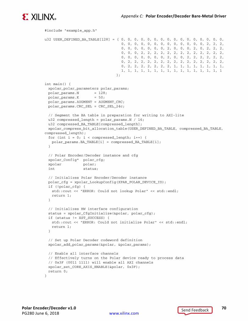
Polar Encoder/Decoder v1.0 70PG280 June 6, 2018 www.xilinx.com
Appendix C: Polar Encoder/Decoder Bare-Metal Driver
#include "example_app.h"
u32 USER_DEFINED_BA_TABLE[128] = { 0, 0, 0, 0, 0, 0, 0, 0, 0, 0, 0, 0, 0, 0, 0, 0,0, 0, 0, 0, 0, 0, 0, 0, 0, 0, 0, 0, 0, 2, 2, 2,0, 0, 0, 0, 0, 0, 0, 2, 0, 0, 0, 2, 0, 2, 2, 2,0, 0, 0, 2, 2, 2, 2, 2, 2, 2, 2, 2, 2, 2, 2, 2,0, 0, 0, 0, 0, 0, 0, 2, 0, 0, 2, 2, 2, 2, 2, 2,0, 2, 2, 2, 2, 2, 2, 2, 2, 2, 2, 2, 2, 2, 2, 2,0, 2, 2, 2, 2, 2, 2, 2, 1, 1, 1, 1, 1, 1, 1, 1,1, 1, 1, 1, 1, 1, 1, 1, 1, 1, 1, 1, 1, 1, 1, 1
};
int main() {xpolar_polar_parameters polar_params;polar_params.N = 128;polar_params.K = 50;polar_params.AUGMENT = AUGMENT_CRC;polar_params.CRC_SEL = CRC_SEL_24c;
// Segment the BA table in preparation for writing to AXI-liteu32 compressed_length = polar_params.N / 16;u32 compressed_BA_TABLE[compressed_length];xpolar_compress_bit_allocation_table(USER_DEFINED_BA_TABLE, compressed_BA_TABLE,
compressed_length);for (int i = 0; i < compressed_length; i++) {polar_params.BA_TABLE[i] = compressed_BA_TABLE[i];
}
// Polar Encoder/Decoder instance and cfgxpolar_Config* polar_cfg;xpolar polar;int status;
// Initializes Polar Encoder/Decoder instancepolar_cfg = xpolar_LookupConfig(XPAR_POLAR_DEVICE_ID);if (!polar_cfg) {std::cout << "ERROR: Could not lookup Polar" << std::endl;return 1;
}
// Initializes HW interface configurationstatus = xpolar_CfgInitialize(&polar, polar_cfg);if (status != XST_SUCCESS) {std::cout << "ERROR: Could not initialize Polar" << std::endl;return 1;
}
// Set up Polar Decoder codeword definitionxpolar_add_polar_params(&polar, &polar_params);
// Enable all interface channels// Effectively turns on the Polar device ready to process data// 0x3F (0011 1111) will enable all AXI channelsxpolar_set_CORE_AXIS_ENABLE(&polar, 0x3F);return 0;
}
Send Feedback

Polar Encoder/Decoder v1.0 71PG280 June 6, 2018 www.xilinx.com
Appendix D
Additional Resources and Legal Notices
Xilinx ResourcesFor support resources such as Answers, Documentation, Downloads, and Forums, see Xilinx Support.
Documentation Navigator and Design HubsXilinx® Documentation Navigator provides access to Xilinx documents, videos, and support resources, which you can filter and search to find information. To open the Xilinx Documentation Navigator (DocNav):
• From the Vivado® IDE, select Help > Documentation and Tutorials.• On Windows, select Start > All Programs > Xilinx Design Tools > DocNav.• At the Linux command prompt, enter docnav.
Xilinx Design Hubs provide links to documentation organized by design tasks and other topics, which you can use to learn key concepts and address frequently asked questions. To access the Design Hubs:
• In the Xilinx Documentation Navigator, click the Design Hubs View tab.• On the Xilinx website, see the Design Hubs page.Note: For more information on Documentation Navigator, see the Documentation Navigator page on the Xilinx website.
Send Feedback

Polar Encoder/Decoder v1.0 72PG280 June 6, 2018 www.xilinx.com
Appendix D: Additional Resources and Legal Notices
ReferencesThese documents provide supplemental material useful with this product guide:
1. AMBA AXI and ACE Protocol Specification (Arm IHI0022E)2. Vivado Design Suite User Guide: Designing IP Subsystems using IP Integrator (UG994)3. Vivado Design Suite User Guide: Designing with IP (UG896)4. Vivado Design Suite User Guide: Getting Started (UG910)5. Vivado Design Suite User Guide: Logic Simulation (UG900)6. Vivado Design Suite User Guide: Programming and Debugging (UG908)7. Vivado Design Suite User Guide: Implementation (UG904)8. AMBA® AXI4-Stream Protocol Specification (Arm IHI 0051A)9. Vivado Design Suite AXI Reference Guide (UG1037)10. 3GPP TS 38.212 V15.1.1 3rd Generation Partnership Project; Technical Specification Group
Radio Access Network; NR; Multiplexing and channel coding (Release 15) (http://www.3gpp.org/dynareport/38212.htm)
Revision HistoryThe following table shows the revision history for this document.
Section Revision06/06/2018
Table 1-1 Added Polar Use Mode Settings table.Table 2-11 Updated Encoder Throughput and Latency table.Table 2-12 Updated Decoder Throughput and Latency table.Table 2-31 Added Supported REG2 Field Combinations table.General updates Added PBCH support.
04/04/2018Initial Xilinx release.
Send Feedback

Polar Encoder/Decoder v1.0 73PG280 June 6, 2018 www.xilinx.com
Appendix D: Additional Resources and Legal Notices
Please Read: Important Legal NoticesThe information disclosed to you hereunder (the “Materials”) is provided solely for the selection and use of Xilinx products. To the maximum extent permitted by applicable law: (1) Materials are made available “AS IS” and with all faults, Xilinx hereby DISCLAIMS ALL WARRANTIES AND CONDITIONS, EXPRESS, IMPLIED, OR STATUTORY, INCLUDING BUT NOT LIMITED TO WARRANTIES OF MERCHANTABILITY, NON-INFRINGEMENT, OR FITNESS FOR ANY PARTICULAR PURPOSE; and (2) Xilinx shall not be liable (whether in contract or tort, including negligence, or under any other theory of liability) for any loss or damage of any kind or nature related to, arising under, or in connection with, the Materials (including your use of the Materials), including for any direct, indirect, special, incidental, or consequential loss or damage (including loss of data, profits, goodwill, or any type of loss or damage suffered as a result of any action brought by a third party) even if such damage or loss was reasonably foreseeable or Xilinx had been advised of the possibility of the same. Xilinx assumes no obligation to correct any errors contained in the Materials or to notify you of updates to the Materials or to product specifications. You may not reproduce, modify, distribute, or publicly display the Materials without prior written consent. Certain products are subject to the terms and conditions of Xilinx’s limited warranty, please refer to Xilinx’s Terms of Sale which can be viewed at https://www.xilinx.com/legal.htm#tos; IP cores may be subject to warranty and support terms contained in a license issued to you by Xilinx. Xilinx products are not designed or intended to be fail-safe or for use in any application requiring fail-safe performance; you assume sole risk and liability for use of Xilinx products in such critical applications, please refer to Xilinx’s Terms of Sale which can be viewed at https://www.xilinx.com/legal.htm#tos.AUTOMOTIVE APPLICATIONS DISCLAIMERAUTOMOTIVE PRODUCTS (IDENTIFIED AS “XA” IN THE PART NUMBER) ARE NOT WARRANTED FOR USE IN THE DEPLOYMENT OF AIRBAGS OR FOR USE IN APPLICATIONS THAT AFFECT CONTROL OF A VEHICLE (“SAFETY APPLICATION”) UNLESS THERE IS A SAFETY CONCEPT OR REDUNDANCY FEATURE CONSISTENT WITH THE ISO 26262 AUTOMOTIVE SAFETY STANDARD (“SAFETY DESIGN”). CUSTOMER SHALL, PRIOR TO USING OR DISTRIBUTING ANY SYSTEMS THAT INCORPORATE PRODUCTS, THOROUGHLY TEST SUCH SYSTEMS FOR SAFETY PURPOSES. USE OF PRODUCTS IN A SAFETY APPLICATION WITHOUT A SAFETY DESIGN IS FULLY AT THE RISK OF CUSTOMER, SUBJECT ONLY TO APPLICABLE LAWS AND REGULATIONS GOVERNING LIMITATIONS ON PRODUCT LIABILITY.© Copyright 2018 Xilinx, Inc. Xilinx, the Xilinx logo, Artix, ISE, Kintex, Spartan, Virtex, Vivado, Zynq, and other designated brands included herein are trademarks of Xilinx in the United States and other countries. AMBA, AMBA Designer, Arm, ARM1176JZ-S, CoreSight, Cortex, PrimeCell, Mali, and MPCore are trademarks of Arm Limited in the EU and other countries.All other trademarks are the property of their respective owners.
Send Feedback