polarized light in nature - texas a&m...
TRANSCRIPT

Polarized Light in Nature
George W. KattawarDepartment of Physics and Institute for Quantum Science
and EngineeringTexas A&M University
Research Colleagues:Meng Gao, Ping Yang,and Yu You

Electromagnetic waves were first postulated by James Clerk Maxwell in 1862 and subsequently confirmedby Heinrich Hertz in 1887.
In 1864, Maxwell wrote "A dynamical theory of the electromagnetic field", where he first proposed that lightwas in fact undulations in the same medium that is the cause of electric and magnetic phenomena.
Maxwell derived a wave form of the electric and magnetic equations, revealing the wave-like nature ofelectric and magnetic fields, and their symmetry. His work in producing a unified model ofelectromagnetism is considered to be one of the greatest advances in physics.
E /t cB 4jB /t cEE 4B 0
And God said:
And then there was light
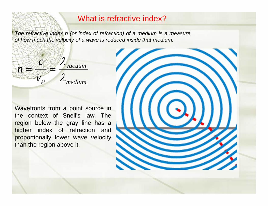
The refractive index n (or index of refraction) of a medium is a measureof how much the velocity of a wave is reduced inside that medium.
Wavefronts from a point source inthe context of Snell's law. Theregion below the gray line has ahigher index of refraction andproportionally lower wave velocitythan the region above it.
n cvP
vacuum
medium
What is refractive index?

Component decomposition of linear Polarization

Linearly Polarized Light

Component decomposition of circular Polarization

Circularly Polarized Light

Linear Polarizer

Quarter Wave Plate
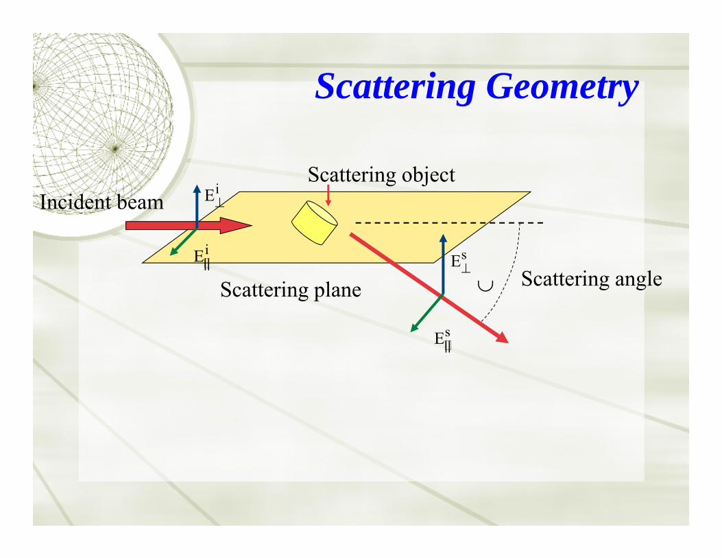
Scattering plane
Scattering Geometry
Incident beam Ei
Ei
Scattering angle
Es
Es
Scattering object
||
||

Stokes vector-Mueller matrix formulationThe electric field can be resolved into components. El and Er are complex oscillatory functions.
The four component Stokes vector can now be defined.They are all real numbers and satisfy the relation
I2 = Q2 + U2 + V2
I Il Ir
Q Il Ir
U I450 I
1350
V IR IL
Is
Qs
Us
Vs
M11 M12 M13 M14M21 M22 M23 M24M31 M32 M33 M34M41 M42 M43 M44
Ii
Qi
Ui
Vi
The Mueller matrix relates the incident and scattered Stokes vectors
E El l̂ Err̂

Homogenous Cylinder Mueller Image
0.5μmλ= 0.532 μm
m=1.35
2.0μm

Stokes vector and polarization parameters
I is the radiance (this is what the human eye sees)Q is the amount of radiation that is polarized in the 0/90 orientation
U is the amount of radiation polarized in the +/-450 orientation
V is the amount of radiation that is right or left circularly polarizedDOP= Degree of polarization= Q2 U2 V2 / I
DOLP = Degree of linear polarization = Q2 U2 / I
DOCP = Degree of circular polarization = |V|/IOrientation of plane of polarization = χ tan-1(U/Q)/2
Ellipticity= Ratio of semiminor to semimajor axis of polarization ellipse = b/a
=tan[(sin-1(V/I))/2]

Nissan car viewed in mid-wave infrared
This data was collected using an Amber MWIR InSb imaging array 256x256. The polarization optics consisted of a rotating quarter wave plate and a linear polarizer. Images were taken at eight different positions of the quarter wave plate (22.5 degree increments) over 180 degrees. The data was reduced to the full Stokes vector using a Fourier transform data reduction technique.
I Q U V

Haidinger’s BrushDirection ofpolarization


97.2°


Contrast enhancement using polarization
Photo taken with a flash lamp and no polarization optics
Photo taken with circular polarized light for illumination and a circular analyzer for viewing

The single-scatter reduced Mueller matrix for ocean water is basically Rayleigh scattering:
M(1800 )1 0 0 00 1 0 00 0 1 00 0 0 1
1 0 0 00 1 0 00 0 1 00 0 0 1
1001
1001

"The aesthetic side of the subject is by no means the leastattractive to me. I hope the day is near when a Ruskin will befound equal to the description of the beauties of coloring, theexquisite gradations of light and shade, and the intricate wonders of symmetrical forms and combinations which are encountered everywhere.”
“On Metallic Colouring in Birds and Insects”, Philos. Mag. 21, 554-567, (1911)
Albert Abraham Michelson


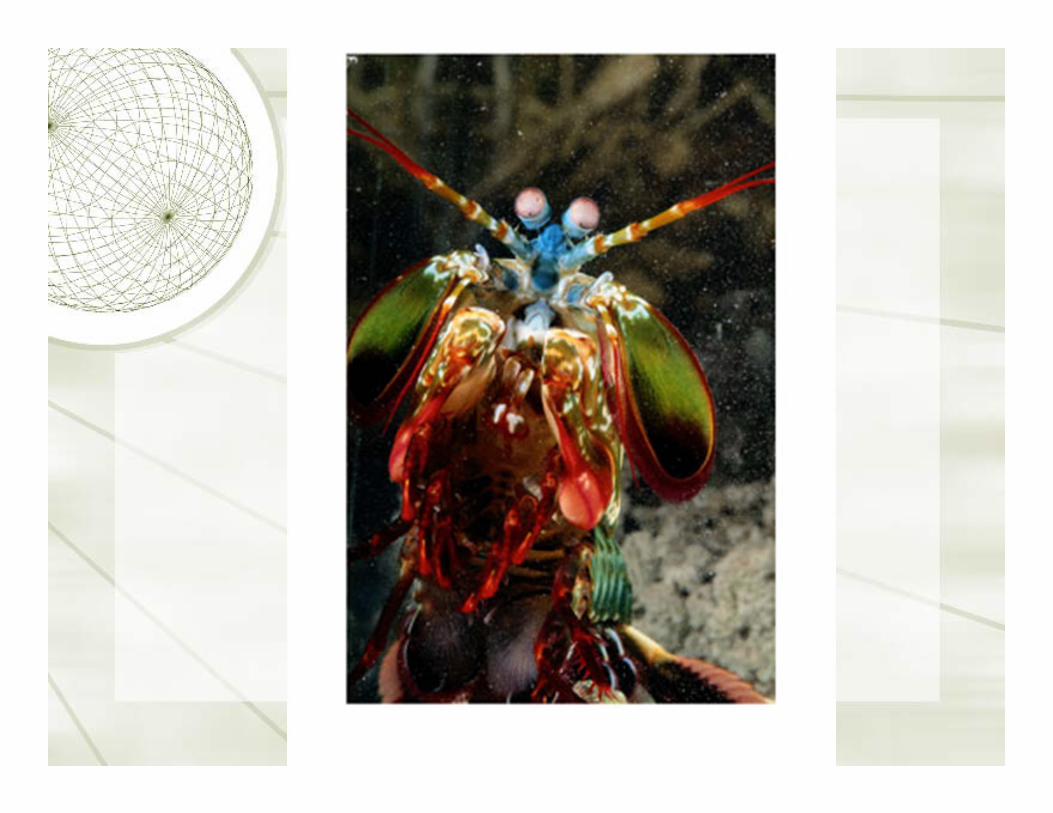

Figure 1. Circular Polarizing Signals and GeneralEye Anatomy in Stomatopods
(A) The stomatopod crustacean Odontodactyluscultrifer (male). The scale bar represents 1 cm.(Photograph by Chrissy Huffard.)
(B) Detail of telson keel (inset in [A]) photographed through a left-handed circular polarizing filter.
(C) As (B) except photographed through a right-handed circular polarizing filter. Note the striking contrast difference compared to (B).
(D) The eye of Odontodactylus scyllarus, a closerelative of O. cultrifer, seen from the front. Thevertical line is section direction and extent in(E). The following abbreviations are used: midband (MB), dorsal hemisphere (DH), and ventral hemisphere (VH). The scale bar represents 800 mm.(E) Diagrammatic representation of a sagittal section (line in [D]) of rows five and six of the midband of the eye of a generalized gonodactyloid stomatopod.
Chiou et al., Current Biology, 18, 429-434 (2008)


Bacillus anthracis


Particle Model-1: SporeOuter coat
Inner coat
Cortex Core
1.0m
0.8m
=0.5m
Philip J. Wyatt, “Differential Light Scattering: a Physical Method for Identifying Living Bacterial Cells”, Applied Optics, Vol.7,No. 10,1879 (1968)

Simulation Models
(a) (b) (c) (d)
1.0μm
0.8μm
1.0 or 2.0μm
0.5 μm
m=1.34 m=1.34

Homogenous Spore Mueller Image = 0o
m=1.34 1.0m
0.8 m
=0.5m
Spore with Core Mueller Image = 0o
Core 1.0m
0.8 m
=0.5m

Homogenous Cylinder Mueller Image
height=1m, =0o
m=1.35
1.0m
0.5m= 0.532 m
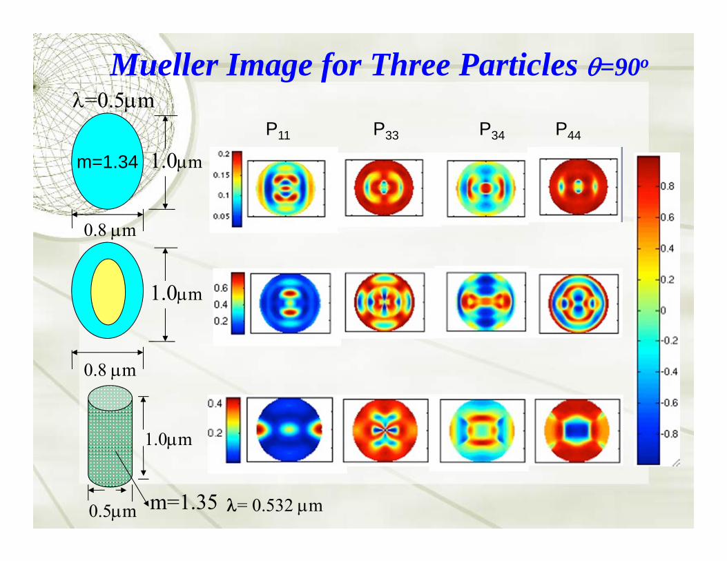
Mueller Image for Three Particles =90o
m=1.34 1.0m
0.8 m
=0.5m
1.0m
0.8 m
0.5m = 0.532 mm=1.35
1.0m
P11 P33 P34 P44

l Skin cancer, most common of all cancers (~50%)l >1M cases of basal and squamous cell carcinomas in the
US/yearl Melanomas account for 5% of all skin cancersl If detected early, over 99% cure ratel Visual inspection is only way to diagnose, but one-third
are misdiagnosedl Subsequent biopsy of the lesion
- invasive, expensive, and time-consuming process
l There is a need for the development of accurate, non-invasive skin cancer detection or facilitated biopsy
Ref: American Cancer Society web site. http://www.cancer.org (updated on 05/06/2009)
Polarized Light and Skin Cancer Detection


Image of a freckle; on the left we show the polarized image on the right the Horizontal image
Image of a melanoma; on the left we show the polarized image on the right the Horizontal image

Interpretation Mueller matrix images based on polar decomposition and statistical
discriminators to distinguish skin cancer
J.R. Chung1, A.M. Baldwin1, J.S. Baba1, C.H. Spiegelman2, M.S. Amoss3, and G.L. Coté1
1Department of Biomedical Engineering2Department of Statistics
3Department of Veterinary Physiology & Pharmacology

• Used Sinclair swine model– 85% incidence of Melanoma
• Imaged 3 types of tissue– Normal Skin– Benign mole– Cancerous Skin
• Three types of analysis– Mueller matrix– CART analysis– Polar Decomposition
Pig Skin – In Vivo

Results: Polar DecompositionNormal Benign Mole Cancer
Depolarization images
• Depolarization Index(DI): To discriminate between cancerous and normal tissue- DI = 0 (no depolarized)- DI = 1 (completely depolarized)- 0 < DI < 1( partially depolarized)
• The benign mole is indistinguishable from the normal tissue.• The cancerous tissue depolarizes light less than the non-cancerous tissue.• But, not visible the boundary of cancer lesions.
-1
1
0

Results: Polar DecompositionNormal Benign Mole Cancer
Diattenuation images
• The diattenuation and retardance images contain information about complexrefractive index of the tissue
• The benign mole is distinguishable from the normal tissue• But, not visible the boundary of cancer lesions.
-1
1
0

Results: Polar Decomposition
Retardance imagesNormal Benign Mole Cancer
• No change for non-cancerous samples (normal, benign mole)• The cancerous lesion is distinguishable from surrounding tissue.• These retardance images are useful
- for differentiating between samples- for boundary identification
-1
1
0
l From Mueller matrix images, there is a noticeable difference between non-cancerous and cancerous tissue.- Underlying structure
l From Depolarization images, cancerous tissue depolarizes less than non-cancerous tissues.
l From Diattenuation images, the benign mole can be distinguished from the normal tissues.
l From Retardance images, not only differentiating between samples, but also for boundary identification.
Conclusion

Plankton as viewed by a squid
Planktonic animal as seen through "regular" visionAs seen when placed between two crossed linear polarizing filtersAs seen by putting the two polarizers at 45° to each other

